Embed Size (px)
Citation preview

Doc. ID 4383_110 v3.1 2016-12-08
SoftDevice SpecificationS132 SoftDevice
v3.1
Contents
Doc. ID 4383_110 v3.1 Page 2
Contents
Chapter 1: S132 SoftDevice............................................................................ 5
Chapter 2: Revision history.............................................................................7
Chapter 3: Documentation........................................................................... 10
Chapter 4: Product overview........................................................................ 11
Chapter 5: Application Programming Interface (API)................................ 125.1 Events - SoftDevice to application...................................................................................................................125.2 Error handling.......................................................................................................................................................... 12
Chapter 6: SoftDevice Manager................................................................... 146.1 SoftDevice enable and disable..........................................................................................................................146.2 Clock source..............................................................................................................................................................146.3 Power management.............................................................................................................................................. 156.4 Memory isolation and runtime protection................................................................................................... 15
Chapter 7: System on Chip (SoC) library..................................................... 18
Chapter 8: System on Chip resource requirements.................................... 208.1 Hardware peripherals............................................................................................................................................208.2 Application signals – software interrupts (SWI).......................................................................................... 228.3 Programmable peripheral interconnect (PPI).............................................................................................. 238.4 SVC number ranges............................................................................................................................................... 238.5 Peripheral runtime protection...........................................................................................................................248.6 External and miscellaneous requirements....................................................................................................24
Chapter 9: Flash memory API....................................................................... 25
Chapter 10: Multiprotocol support.............................................................. 2710.1 Non-concurrent multiprotocol implementation...................................................................................... 2710.2 Concurrent multiprotocol implementation using the Radio Timeslot API..................................... 27
10.2.1 Request types....................................................................................................................................... 2710.2.2 Request priorities................................................................................................................................ 2810.2.3 Timeslot length....................................................................................................................................2810.2.4 Scheduling............................................................................................................................................. 2810.2.5 High frequency clock configuration............................................................................................ 2810.2.6 Performance considerations........................................................................................................... 2810.2.7 Radio Timeslot API..............................................................................................................................29
10.3 Radio Timeslot API usage scenarios..............................................................................................................31

Contents
Doc. ID 4383_110 v3.1 Page 3
10.3.1 Complete session example............................................................................................................. 3110.3.2 Blocked timeslot scenario................................................................................................................3210.3.3 Canceled timeslot scenario............................................................................................................. 3310.3.4 Radio Timeslot extension example.............................................................................................. 34
Chapter 11: Bluetooth® low energy protocol stack.....................................3611.1 Profile and service support...............................................................................................................................3611.2 Bluetooth® low energy features...................................................................................................................... 3811.3 Limitations on procedure concurrency........................................................................................................4111.4 BLE role configuration........................................................................................................................................42
Chapter 12: Radio Notification.....................................................................4312.1 Radio Notification Signals................................................................................................................................. 4312.2 Radio Notification on connection events as a Central...........................................................................4612.3 Radio Notification on connection events as a Peripheral..................................................................... 4812.4 Radio Notification with concurrent peripheral and central connection events............................5012.5 Radio Notification with Connection Event Length Extension............................................................. 5012.6 Power Amplifier and Low Noise Amplifier control configuration (PA/LNA)...................................51
Chapter 13: Master Boot Record and bootloader.......................................5313.1 Master Boot Record.............................................................................................................................................5313.2 Bootloader...............................................................................................................................................................5313.3 Master Boot Record (MBR) and SoftDevice reset procedure............................................................... 5413.4 Master Boot Record (MBR) and SoftDevice initialization procedure.................................................55
Chapter 14: SoftDevice information structure............................................56
Chapter 15: SoftDevice memory usage....................................................... 5715.1 Memory resource map and usage.................................................................................................................57
15.1.1 Memory resource requirements....................................................................................................5815.2 Attribute table size.............................................................................................................................................. 5915.3 Role configuration................................................................................................................................................5915.4 Security configuration........................................................................................................................................ 5915.5 Vendor specific UUID counts...........................................................................................................................59
Chapter 16: Scheduling................................................................................. 6116.1 SoftDevice timing-activities and priorities..................................................................................................6116.2 Initiator timing.......................................................................................................................................................6216.3 Connection timing as a Central......................................................................................................................6416.4 Scanner timing...................................................................................................................................................... 6516.5 Advertiser (connectable and non-connectable) timing.........................................................................6716.6 Peripheral connection setup and connection timing.............................................................................6716.7 Connection timing with Connection Event Length Extension............................................................6916.8 Flash API timing....................................................................................................................................................6916.9 Timeslot API timing............................................................................................................................................. 6916.10 Suggested intervals and windows.............................................................................................................. 70
Chapter 17: Interrupt model and processor availability............................7217.1 Exception model...................................................................................................................................................72

Contents
Doc. ID 4383_110 v3.1 Page 4
17.1.1 Interrupt forwarding to the application.....................................................................................7217.1.2 Interrupt latency due to System on Chip (SoC) framework................................................ 72
17.2 Interrupt priority levels...................................................................................................................................... 7317.3 Processor usage patterns and availability.................................................................................................. 75
17.3.1 Flash API processor usage patterns............................................................................................. 7517.3.2 Radio Timeslot API processor usage patterns..........................................................................7617.3.3 BLE processor usage patterns........................................................................................................ 7717.3.4 Interrupt latency when using multiple modules and roles................................................. 82
Chapter 18: BLE data throughput................................................................ 84
Chapter 19: BLE power profiles.................................................................... 8719.1 Advertising event................................................................................................................................................. 8719.2 Peripheral connection event............................................................................................................................8819.3 Scanning event..................................................................................................................................................... 8819.4 Central connection event..................................................................................................................................89
Chapter 20: SoftDevice identification and revision scheme......................9120.1 MBR distribution and revision scheme........................................................................................................ 92

Doc. ID 4383_110 v3.1 Page 5
Chapter 1
S132 SoftDeviceThe S132 SoftDevice is a Bluetooth® low energy (BLE) central and peripheral protocol stack solution. It supportsup to eight connections with an additional observer and a broadcaster role all running concurrently. The S132SoftDevice integrates a BLE Controller and Host, and provides a full and flexible API for building Bluetooth®
Smart nRF52 System on Chip (SoC) solutions.
Key features Applications
• Bluetooth® 4.2 compliant low energy single-modeprotocol stack suitable for Bluetooth® Smart products
• Concurrent central, observer, peripheral, andbroadcaster roles with up to eight concurrentconnections along with one Observer and oneBroadcaster
• Configurable number of connections andbandwidth per connection to optimize memory andperformance
• Configurable attribute table size• Custom UUID support• Link layer• LL Privacy• LE Data Packet Length Extension• L2CAP, ATT, and SM protocols• LE Secure Connections pairing model• GATT and GAP APIs• GATT Client and Server• Configurable ATT MTU
• Complementary nRF5 SDK including Bluetooth®
profiles and example applications• Master Boot Record for over-the-air device firmware
update
• SoftDevice, application, and bootloader can beupdated separately
• Memory isolation between the application and theprotocol stack for robustness and security
• Thread-safe supervisor-call based API• Asynchronous, event-driven behavior• No RTOS dependency
• Any RTOS can be used• No link-time dependencies
• Standard ARM® Cortex®-M4 project configurationfor application development
• Support for concurrent and non-concurrentmultiprotocol operation
• Concurrent with the Bluetooth® stack using RadioTimeslot API
• Sports and fitness devices
• Sports watches• Bike computers
• Personal Area Networks
• Health and fitness sensor and monitoringdevices
• Medical devices• Key fobs and wrist watches
• Home automation• AirFuel wireless charging• Remote control toys• Computer peripherals and I/O devices
• Mice• Keyboards• Multi-touch trackpads
• Interactive entertainment devices
• Remote controls• Gaming controllers

1 S132 SoftDevice
Doc. ID 4383_110 v3.1 Page 6
Key features Applications
• Alternate protocol stack in application space• Support for control of external Power Amplifiers and
Low Noise Amplifiers
Doc. ID 4383_110 v3.1 Page 7
Chapter 2
Revision historyDate Version Description
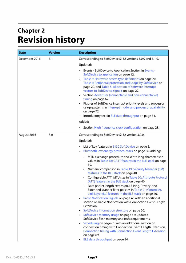
December 2016 3.1 Corresponding to SoftDevice S132 versions 3.0.0 and 3.1.0.
Updated:
• Events - SoftDevice to Application Section in Events -SoftDevice to application on page 12.
• Table 3: Hardware access type definitions on page 20,Table 4: Peripheral protection and usage by SoftDevice onpage 20, and Table 5: Allocation of software interruptvectors to SoftDevice signals on page 22.
• Section Advertiser (connectable and non-connectable)timing on page 67.
• Figures of SoftDevice interrupt priority levels and processorusage patterns in Interrupt model and processor availabilityon page 72.
• Introductory text in BLE data throughput on page 84.
Added:
• Section High frequency clock configuration on page 28.
August 2016 3.0 Corresponding to SoftDevice S132 version 3.0.0.
Updated:
• List of key features in S132 SoftDevice on page 5.• Bluetooth low energy protocol stack on page 36, adding:
• MTU exchange procedure and Write long characteristicvalues in Table 18: GATT features in the BLE stack on page39.
• Numeric comparison in Table 19: Security Manager (SM)features in the BLE stack on page 40.
• Configurable ATT_MTU size in Table 20: Attribute Protocol(ATT) features in the BLE stack on page 40.
• Data packet length extension, LE Ping, Privacy, andExtended scanner filter policies in Table 21: Controller,Link Layer (LL) features in the BLE stack on page 40.
• Radio Notification Signals on page 43 with an additionalsection on Radio Notification with Connection Event LengthExtension.
• SoftDevice information structure on page 56.• SoftDevice memory usage on page 57: updated
SoftDevice flash memory and RAM requirements.• Scheduling on page 61 with an additional section on
connection timing with Connection Event Length Extension,Connection timing with Connection Event Length Extensionon page 69.
• BLE data throughput on page 84:

2 Revision history
Doc. ID 4383_110 v3.1 Page 8
Date Version Description
• Updated figures of SoftDevice data throughput for singlelink on Table 39: Maximum data throughput with asingle peripheral or central connection and a connectioninterval of 7.5 ms on page 84,
• Added table for maximum achievable single-linkthroughput: Table 39: Maximum data throughput with asingle peripheral or central connection and a connectioninterval of 7.5 ms on page 84.
April 2016 2.0 Corresponding to SoftDevice S132 version 2.0.0. The SDSrevision 1.0 is intentionally skipped to align with the SoftDeviceversion and with the S130 SDS version.
Updated:
• SoftDevice Manager on page 14. Added documentationon (previously in Appendix A):
• Clock source,• Power management,• Memory isolation and runtime protection
• Hardware peripherals on page 20.• Programmable peripheral interconnect (PPI) on page 23.
Documented PPI channel changes.• Flash memory API on page 25. Documented changes and
new numbers.• Profile and service support on page 36. Updated the list
of profiles and services currently adopted by the Bluetooth®
Special Interest Group.• Radio Notification on page 43.• Master Boot Record on page 53.• Scheduling on page 61 (previously Chapter 14: Multilink
scheduling).• Interrupt model and processor availability on page 72.
Updated section to align with the new SoftDevice prioritylevel structure.
• BLE data throughput on page 84. Updateddocumentation with new numbers.
Added:
• Application Programming Interface (API) on page 12(previously in Appendix A). Now also including section Errorhandling on page 12.
• BLE role configuration on page 42.• Power Amplifier and Low Noise Amplifier control
configuration (PA/LNA) on page 51.• SoftDevice memory usage on page 57 (Memory resource
map and usage on page 57 and Attribute table sizeon page 59 previously in Chapter 13: System on Chipresource requirements; Call Stack and Heap informationpreviously in Appendix A can be found under Memoryresource requirements on page 58).
• SoftDevice timing-activities and priorities on page 61.

2 Revision history
Doc. ID 4383_110 v3.1 Page 9
Date Version Description
• Timeslot API timing on page 69.
Several chapters have been restructured, relocated and revised.Appendix A is removed.
June 2015 0.5 Preliminary release.

Doc. ID 4383_110 v3.1 Page 10
Chapter 3
DocumentationAdditional recommended reading for developing applications using the SoftDevice on the nRF52 SoCincludes the product specification, errata, compatibility matrix, and Bluetooth® core specification.
A list of the recommended documentation for the SoftDevice is given in Table 1: S132 SoftDevice coredocumentation on page 10.
Table 1: S132 SoftDevice core documentation
Documentation Description
nRF52832 Product Specification Contains a description of the hardware, peripherals,and electrical specifications specific to the nRF52832IC.
nRF52832 Errata Contains information on anomalies related to thenRF52832 IC.
nRF52 Series Compatibility Matrix Contains information on the compatibility betweennRF52 Integrated Circuit (IC) revisions, SoftDevicesand SoftDevice Specifications, SDKs, developmentkits, documentation, and Qualified DesignIdentifications (QDIDs).
Bluetooth Core Specification The Bluetooth® Core Specification version 4.2,Volumes 1, 3, 4, and 6, describes Bluetooth®
terminology which is used throughout theSoftDevice Specification.

Doc. ID 4383_110 v3.1 Page 11
Chapter 4
Product overviewThe S132 SoftDevice is a precompiled and linked binary image implementing a Bluetooth® 4.2 low energyprotocol stack for the nRF52 Series of SoCs.
See the nRF52 Series Compatibility Matrix for SoftDevice/IC compatibility information.
nRF API
Application – Profiles and Services
App-Specific peripheral
drivers
nRF5x HW
nRF SoftDevice
BLE Protocol Stack
SoftDevice Manager
SoC Library
Protocol API (SV Calls)
Master Boot RecordCMSIS
Figure 1: System on Chip application with the SoftDevice
Figure 1: System on Chip application with the SoftDevice on page 11 is a block diagram of the nRF52series software architecture. It includes the standard ARM® CMSIS interface for nRF52 hardware, a master bootrecord, profile and application code, application specific peripheral drivers, and a firmware module identifiedas a SoftDevice.
A SoftDevice consists of three main components:
• SoC Library - Implementation and nRF API for shared hardware resource management (applicationcoexistence).
• SoftDevice Manager - Implementation and nRF API for SoftDevice management (enabling/disabling theSoftDevice, etc.).
• Bluetooth® 4.2 low energy protocol stack - Implementation of protocol stack and API.
The Application Programming Interface (API) is a set of standard C language functions and data types,provided as a series of header files, that give the application complete compiler and linker independence fromthe SoftDevice implementation. See Application Programming Interface (API) on page 12 for more details.
The SoftDevice enables the application developer to develop their code as a standard ARM® Cortex® -M4project without having the need to integrate with proprietary IC vendor software frameworks. This means thatany ARM® Cortex® -M4-compatible toolchain can be used to develop Bluetooth® low energy applications withthe SoftDevice.
The SoftDevice can be programmed onto compatible nRF52 Series ICs during both development andproduction.

Doc. ID 4383_110 v3.1 Page 12
Chapter 5
Application Programming Interface(API)The SoftDevice Application Programming Interface (API) is available to applications as a C programminglanguage interface based on SuperVisor Calls (SVC) and defined in a set of header files.
In addition to a Protocol API enabling wireless applications, there is an nRF API that exposes the functionalityof both the SoftDevice Manager and the SoC library.
Important: When the SoftDevice is disabled, only a subset of the SoftDevice APIs is available tothe application (see S132 SoftDevice API). For more information about enabling and disabling theSoftDevice, see SoftDevice enable and disable on page 14.
SVCs are software triggered interrupts conforming to a procedure call standard for parameter passingand return values. Each SoftDevice API call triggers an SVC interrupt. The SoftDevice SVC interrupt handlerlocates the correct SoftDevice function, allowing applications to compile without any API function addressinformation at compile time. This removes the necessity for the application to link the SoftDevice. Theheader files contain all information required for the application to invoke the API functions with standardprogramming language prototypes. This SVC interface makes SoftDevice API calls thread-safe; they can beinvoked from the application's different priority levels without additional synchronization mechanisms.
Important: SoftDevice API functions can only be called from a lower interrupt priority level (highernumerical value for the priority level) than the SVC priority. For more information, see Interrupt prioritylevels on page 73.
5.1 Events - SoftDevice to applicationSoftware triggered interrupts in a reserved IRQ are used to signal events from the SoftDevice to theapplication. The application is then responsible for handling the interrupt and for invoking the relevantSoftDevice functions to obtain the event data.
The application must respond to and process the SoftDevice events to ensure a proper functioning of theSoftDevice. If events for BLE control procedures are not serviced, the procedures may time out and resultin a link disconnection. If data received by the SoftDevice from the peer is not fetched in time, the internalSoftDevice data buffers may become full and no more data can be received.
For further details on how to implement the handling of these events, see the nRF5 Software Development Kit(nRF5 SDK) documentation.
5.2 Error handlingAll SoftDevice API functions return a 32-bit error code. The application must check this error code to confirmwhether a SoftDevice API function call was successful.
Unrecoverable failures (faults) detected by the SoftDevice will be reported to the application by a registered,fault handling callback function. A pointer to the fault handler must be provided by the application uponSoftDevice initialization. The fault handler is then used to notify of unrecoverable errors and the type of error isindicated as a parameter to the fault handler.
The following types of faults can be reported to the application through the fault handler:
• SoftDevice assertions.

5 Application Programming Interface (API)
Doc. ID 4383_110 v3.1 Page 13
• Attempts by the application to perform unallowed memory accesses, either against SoftDevice memoryprotection rules or to protected peripheral configuration registers at runtime.
The fault handler callback is invoked by the SoftDevice in HardFault context, with all interrupts disabled.

Doc. ID 4383_110 v3.1 Page 14
Chapter 6
SoftDevice ManagerThe SoftDevice Manager (SDM) API allows the application to manage the SoftDevice on a top level. It controlsthe SoftDevice state and configures the behavior of certain SoftDevice core functionality.
When enabling the SoftDevice, the SDM configures the following:
• the low frequency clock (LFCLK) source, see Clock source on page 14.• the interrupt management, see SoftDevice enable and disable on page 14.• the embedded protocol stack.
In addition, it enables the SoftDevice RAM and peripheral protection. See Memory isolation and runtimeprotection on page 15.
Detailed documentation of the SDM API is made available with the Software Development Kits (SDK).
6.1 SoftDevice enable and disableWhen the SoftDevice is not enabled, the Protocol API and parts of the SoC library API are not available to theapplication.
When the SoftDevice is not enabled, most of the SoC's resources are available to the application. However, thefollowing restrictions apply:
• SVC numbers 0x10 to 0xFF are reserved.• SoftDevice program (flash) memory is reserved.• A few bytes of RAM are reserved. See Memory resource map and usage on page 57 for more details.
Once the SoftDevice has been enabled, more restrictions apply:
• Some RAM will be reserved. See Memory isolation and runtime protection on page 15 for more details.• Some peripherals will be reserved. See Hardware peripherals on page 20 for more details.• Some of the peripherals that are reserved will have a SoC library interface.• Interrupts from the reserved SoftDevice peripherals will not be forwarded to the application. See Interrupt
forwarding to the application on page 72 for more details.• The reserved peripherals are reset upon SoftDevice disable.• nrf_nvic_ functions must be used instead of CMSIS NVIC_ functions for safe use of the SoftDevice.• SoftDevice activity in high priority levels may interrupt the application, increasing the maximum interrupt
latency. For more information, see Interrupt model and processor availability on page 72.
6.2 Clock sourceThe SoftDevice can use one of two available low frequency clock sources: the internal RC Oscillator, or externalCrystal Oscillator.
The application must provide the selected clock source and some clock source characteristics, such asaccuracy, when it enables the SoftDevice. The SoftDevice Manager is responsible for configuring the lowfrequency clock source and for keeping it calibrated, when the RC oscillator is the selected clock source.
If the SoftDevice is configured with the internal RC oscillator clock option, clock calibration is requiredperiodically, and when a temperature change of more than 0.5 degrees has occurred to adjust the RC oscillatorfrequency. See the nRF52832 Product Specification for more information. The SoftDevice will perform thisfunction automatically. The application may choose how often the SoftDevice will make a measurement todetect temperature change, depending on how frequently significant temperature changes are expected
6 SoftDevice Manager
Doc. ID 4383_110 v3.1 Page 15
to occur in the intended environment of the end product. It is recommended to use a temperature pollinginterval of 4 seconds, and to force clock calibration every second interval (.ctiv=32, .temp_ctiv=2).
6.3 Power managementThe SoftDevice implements a simple to use SoftDevice POWER API for optimized power management.
The application must use this API when the SoftDevice is enabled to ensure correct function. When theSoftDevice is disabled, the application must use the hardware abstraction (CMSIS) interfaces for powermanagement directly.
When waiting for application events using the API, the CPU goes to an IDLE state whenever the SoftDevice isnot using the CPU, and interrupts handled directly by the SoftDevice do not wake the application. Applicationinterrupts will wake the application as expected. When going to system OFF, the API ensures the SoftDeviceservices are stopped before powering down.
6.4 Memory isolation and runtime protectionThe SoftDevice data memory and peripherals can be sandboxed and runtime protected to prevent theapplication from interfering with the SoftDevice execution, ensuring robust and predictable performance.
Sandboxing1 and runtime protection can allow memory access violations to be detected at development time.This ensures that developed applications will not inadvertently interfere with the correct functioning of theSoftDevice.
Sandboxing is enabled by default when the SoftDevice is enabled and disabled when the SoftDevice isdisabled. When enabled, SoftDevice RAM and peripheral registers are protected against write access by theapplication. The application will have read access to SoftDevice RAM and peripheral registers.
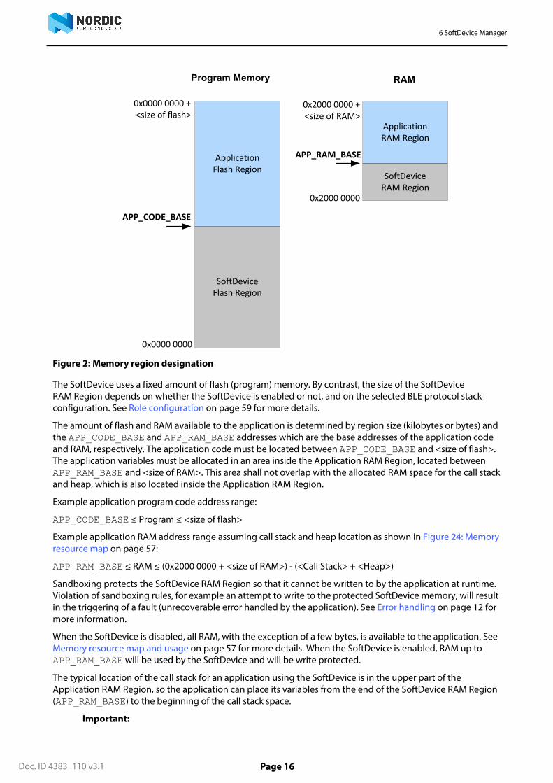
The program memory is divided into two regions at compile time. The SoftDevice Flash Region is locatedbetween addresses 0x00000000 and APP_CODE_BASE - 1 and is occupied by the SoftDevice. TheApplication Flash Region is located between the addresses APP_CODE_BASE and the last valid address in theflash memory and is available to the application.
The RAM is split into two regions, which are defined at runtime, when the SoftDevice is enabled. TheSoftDevice RAM Region is located between the addresses 0x20000000 and APP_RAM_BASE - 1 and isused by the SoftDevice. The Application RAM Region is located between the addresses APP_RAM_BASE andthe top of RAM and is available to the application.
Figure 2: Memory region designation on page 16 presents an overview of the regions.
1 A sandbox is a set of memory access restrictions imposed on the application.
6 SoftDevice Manager
Doc. ID 4383_110 v3.1 Page 16
SoftDevice Flash Region
Application Flash Region
APP_CODE_BASE
0x0000 0000
0x0000 0000 + <size of flash>
Program Memory RAM
SoftDevice RAM Region
Application RAM Region
APP_RAM_BASE
0x2000 0000
0x2000 0000 + <size of RAM>
Figure 2: Memory region designation
The SoftDevice uses a fixed amount of flash (program) memory. By contrast, the size of the SoftDeviceRAM Region depends on whether the SoftDevice is enabled or not, and on the selected BLE protocol stackconfiguration. See Role configuration on page 59 for more details.
The amount of flash and RAM available to the application is determined by region size (kilobytes or bytes) andthe APP_CODE_BASE and APP_RAM_BASE addresses which are the base addresses of the application codeand RAM, respectively. The application code must be located between APP_CODE_BASE and <size of flash>.The application variables must be allocated in an area inside the Application RAM Region, located betweenAPP_RAM_BASE and <size of RAM>. This area shall not overlap with the allocated RAM space for the call stackand heap, which is also located inside the Application RAM Region.
Example application program code address range:
APP_CODE_BASE ≤ Program ≤ <size of flash>
Example application RAM address range assuming call stack and heap location as shown in Figure 24: Memoryresource map on page 57:
APP_RAM_BASE ≤ RAM ≤ (0x2000 0000 + <size of RAM>) - (<Call Stack> + <Heap>)
Sandboxing protects the SoftDevice RAM Region so that it cannot be written to by the application at runtime.Violation of sandboxing rules, for example an attempt to write to the protected SoftDevice memory, will resultin the triggering of a fault (unrecoverable error handled by the application). See Error handling on page 12 formore information.
When the SoftDevice is disabled, all RAM, with the exception of a few bytes, is available to the application. SeeMemory resource map and usage on page 57 for more details. When the SoftDevice is enabled, RAM up toAPP_RAM_BASE will be used by the SoftDevice and will be write protected.
The typical location of the call stack for an application using the SoftDevice is in the upper part of theApplication RAM Region, so the application can place its variables from the end of the SoftDevice RAM Region(APP_RAM_BASE) to the beginning of the call stack space.
Important:

6 SoftDevice Manager
Doc. ID 4383_110 v3.1 Page 17
• The location of the call stack is communicated to the SoftDevice through the contents of the MainStack Pointer (MSP) register.
• Do not change the value of MSP dynamically (i.e. never set the MSP register directly).• The RAM located in the SoftDevice RAM Region will be overwritten once the SoftDevice is enabled.• The SoftDevice RAM Region will be not be cleared or restored to default values after disabling the
SoftDevice, so the application must treat the contents of the region as uninitialized memory.
Doc. ID 4383_110 v3.1 Page 18
Chapter 7
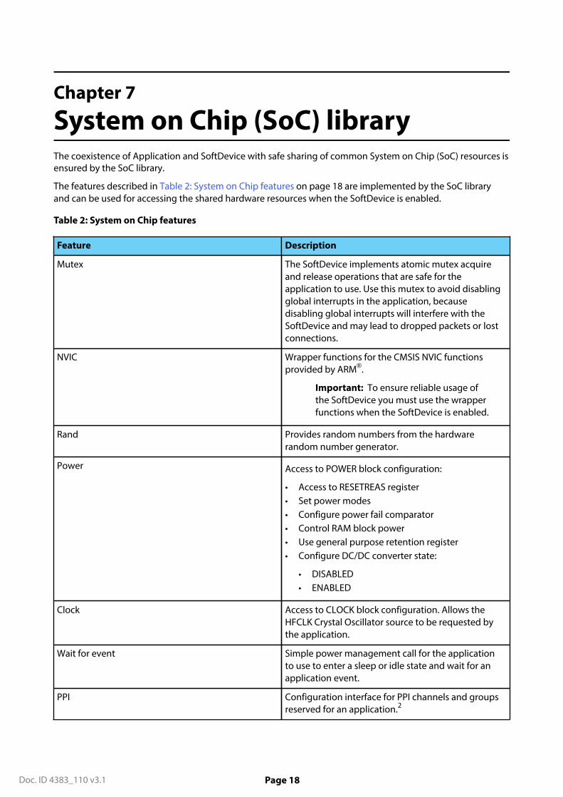
System on Chip (SoC) libraryThe coexistence of Application and SoftDevice with safe sharing of common System on Chip (SoC) resources isensured by the SoC library.
The features described in Table 2: System on Chip features on page 18 are implemented by the SoC libraryand can be used for accessing the shared hardware resources when the SoftDevice is enabled.
Table 2: System on Chip features
Feature Description
Mutex The SoftDevice implements atomic mutex acquireand release operations that are safe for theapplication to use. Use this mutex to avoid disablingglobal interrupts in the application, becausedisabling global interrupts will interfere with theSoftDevice and may lead to dropped packets or lostconnections.
NVIC Wrapper functions for the CMSIS NVIC functionsprovided by ARM®.
Important: To ensure reliable usage ofthe SoftDevice you must use the wrapperfunctions when the SoftDevice is enabled.
Rand Provides random numbers from the hardwarerandom number generator.
Power Access to POWER block configuration:
• Access to RESETREAS register• Set power modes• Configure power fail comparator• Control RAM block power• Use general purpose retention register• Configure DC/DC converter state:
• DISABLED• ENABLED
Clock Access to CLOCK block configuration. Allows theHFCLK Crystal Oscillator source to be requested bythe application.
Wait for event Simple power management call for the applicationto use to enter a sleep or idle state and wait for anapplication event.
PPI Configuration interface for PPI channels and groupsreserved for an application.2

7 System on Chip (SoC) library
Doc. ID 4383_110 v3.1 Page 19
Feature Description
Radio Timeslot API Schedule other radio protocol activity, or periods ofradio inactivity. For more information, see Concurrentmultiprotocol implementation using the RadioTimeslot API on page 27.
Radio Notification Configure Radio Notification signals on ACTIVE and/or nACTIVE. See Radio Notification Signals on page43.
Block Encrypt (ECB) Safe use of 128-bit AES encrypt HW accelerator.
Event API Fetch asynchronous events generated by the SoClibrary.
Flash memory API Application access to flash write, erase, and protect.Can be safely used during all protocol stack states. 2
See Flash memory API on page 25.
Temperature Application access to the temperature sensor.
2 This can also be used when the SoftDevice is disabled.

Doc. ID 4383_110 v3.1 Page 20
Chapter 8
System on Chip resourcerequirementsThis section describes how the SoftDevice, including the Master Boot Record (MBR), uses the System onChip (SoC) resources. The SoftDevice requirements are shown for both when the SoftDevice is enabled anddisabled.
The SoftDevice and MBR (see Master Boot Record and bootloader on page 53) are designed to be installedon the nRF SoC in the lower part of the code memory space. After a reset, the MBR will use some RAM to storestate information. When the SoftDevice is enabled, it uses resources on the SoC including RAM and hardwareperipherals like the radio. For the amount of RAM required by the SoftDevice see SoftDevice memory usage onpage 57.
8.1 Hardware peripheralsSoftDevice access types are used to indicate the availability of hardware peripherals to the application. Theavailability varies per hardware peripheral and depends on whether the SoftDevice is enabled or disabled.
Table 3: Hardware access type definitions
Access type Definition
Restricted Used by the SoftDevice and outside the application sandbox.
The application has limited access through the SoftDevice API.
Blocked Used by the SoftDevice and outside the application sandbox.
The application has no access. Interrupts from blocked peripherals areforwarded to the SoftDevice by the MBR and are not available to theapplication, even inside a Radio Timeslot API timeslot.
Open Not used by the SoftDevice.
The application has full access.
Table 4: Peripheral protection and usage by SoftDevice
ID Base address Instance Access
SoftDeviceenabled
Access
SoftDevicedisabled
0 0x40000000 CLOCK Restricted Open
0 0x40000000 POWER Restricted Open
0 0x40000000 BPROT Restricted Open
1 0x40001000 RADIO Blocked6 Open
2 0x40002000 UART0 / UARTE0 Open Open

8 System on Chip resource requirements
Doc. ID 4383_110 v3.1 Page 21
ID Base address Instance Access
SoftDeviceenabled
Access
SoftDevicedisabled
3 0x40003000 TWIM0 / TWIS0 /SPIM0 / SPIS0 /
SPI0 / TWI0
Open Open
4 0x40004000 SPI1 / TWIS1 /SPIM1 / TWI1 /TWIM1 / SPIS1
Open Open
...
6 0x40006000 GPIOTE Open Open
7 0x40007000 SAADC Open Open
8 0x40008000 TIMER0 Blocked6 Open
9 0x40009000 TIMER1 Open Open
10 0x4000A000 TIMER2 Open Open
11 0x4000B000 RTC0 Blocked Open
12 0x4000C000 TEMP Restricted Open
13 0x4000D000 RNG Restricted Open
14 0x4000E000 ECB Restricted Open
15 0x4000F000 CCM Blocked7 Open
15 0x4000F000 AAR Blocked7 Open
16 0x40010000 WDT Open Open
17 0x40011000 RTC1 Open Open
18 0x40012000 QDEC Open Open
19 0x40013000 LPCOMP / COMP Open Open
20 0x40014000 EGU0 / SWI0 Open Open
21 0x40015000 EGU1 / SWI1 /Radio Notification
Restricted8 Open
22 0x40016000 EGU2 / SWI2 /SoftDevice Event
Blocked Open
23 0x40017000 EGU3 / SWI3 Open Open
24 0x40018000 EGU4 / SWI4 Blocked Open
25 0x40019000 EGU5 / SWI5 Blocked Open
...
30 0x4001E000 NVMC Restricted Open
31 0x4001F000 PPI Open3 Open
32 0x40020000 MWU Restricted4 Open

8 System on Chip resource requirements
Doc. ID 4383_110 v3.1 Page 22
ID Base address Instance Access
SoftDeviceenabled
Access
SoftDevicedisabled
33 0x40021000 PWM1 Open Open
34 0x40022000 PWM2 Open Open
35 0x40023000 SPI2 / SPIS2 / SPIM2 Open Open
36 0x40024000 RTC2 Open Open
37 0x40025000 I2S Open Open
38 0x40026000 FPU Open Open
NA 0x10000000 FICR Blocked Blocked
NA 0x10001000 UICR Restricted Open
NA 0x50000000 GPIO P0 Open Open
NA 0xE000E100 NVIC Restricted5 Open
8.2 Application signals – software interrupts (SWI)Software interrupts are used by the SoftDevice to signal events to the application.
Table 5: Allocation of software interrupt vectors to SoftDevice signals
SWI Peripheral ID Interrupt priority SoftDevice Signal
0 20 - Unused by the SoftDevice and available tothe application.
1 21 7 Radio Notification - optionally configuredthrough API.
2 22 7 SoftDevice Event Notification.
3 23 - Unused by the SoftDevice and available tothe application.
3 See section Programmable peripheral interconnect (PPI) on page 23 for limitations on the use of PPIwhen the SoftDevice is enabled.
4 See section Memory isolation and runtime protection on page 15 and Peripheral runtime protection onpage 24 for limitations on the use of MWU when the SoftDevice is enabled.
5 Not protected. For robust system function, the application program must comply with the restriction anduse the NVIC API for configuration when the SoftDevice is enabled.
6 The peripheral is available to the application through the Radio Timeslot API, see Concurrentmultiprotocol implementation using the Radio Timeslot API on page 27. When inside Radio TimeslotAPI timeslots, interrupts are forwarded to the SoftDevice which, in turn, invokes the signal handlercallback functions, which are provided by the application, within the forwarded interrupt context.
7 The peripheral is available to application during a Radio Timeslot API timeslot, see Concurrentmultiprotocol implementation using the Radio Timeslot API on page 27.
8 Blocked only when Radio Notification signal is enabled. See Application signals – software interrupts(SWI) on page 22 for software interrupt allocation.
8 System on Chip resource requirements
Doc. ID 4383_110 v3.1 Page 23
SWI Peripheral ID Interrupt priority SoftDevice Signal
4 24 4 SoftDevice processing - not userconfigurable.
5 25 4 SoftDevice processing - not userconfigurable.
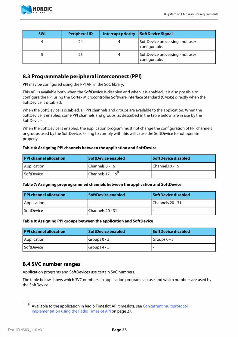
8.3 Programmable peripheral interconnect (PPI)PPI may be configured using the PPI API in the SoC library.
This API is available both when the SoftDevice is disabled and when it is enabled. It is also possible toconfigure the PPI using the Cortex Microcontroller Software Interface Standard (CMSIS) directly when theSoftDevice is disabled.
When the SoftDevice is disabled, all PPI channels and groups are available to the application. When theSoftDevice is enabled, some PPI channels and groups, as described in the table below, are in use by theSoftDevice.
When the SoftDevice is enabled, the application program must not change the configuration of PPI channelsor groups used by the SoftDevice. Failing to comply with this will cause the SoftDevice to not operateproperly.
Table 6: Assigning PPI channels between the application and SoftDevice
PPI channel allocation SoftDevice enabled SoftDevice disabled
Application Channels 0 - 16 Channels 0 - 19
SoftDevice Channels 17 - 199 -
Table 7: Assigning preprogrammed channels between the application and SoftDevice
PPI channel allocation SoftDevice enabled SoftDevice disabled
Application - Channels 20 - 31
SoftDevice Channels 20 - 31 -
Table 8: Assigning PPI groups between the application and SoftDevice
PPI channel allocation SoftDevice enabled SoftDevice disabled
Application Groups 0 - 3 Groups 0 - 5
SoftDevice Groups 4 - 5 -
8.4 SVC number rangesApplication programs and SoftDevices use certain SVC numbers.
The table below shows which SVC numbers an application program can use and which numbers are used bythe SoftDevice.
9 Available to the application in Radio Timeslot API timeslots, see Concurrent multiprotocolimplementation using the Radio Timeslot API on page 27.
8 System on Chip resource requirements
Doc. ID 4383_110 v3.1 Page 24
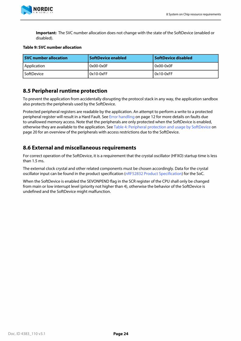
Important: The SVC number allocation does not change with the state of the SoftDevice (enabled ordisabled).
Table 9: SVC number allocation
SVC number allocation SoftDevice enabled SoftDevice disabled
Application 0x00-0x0F 0x00-0x0F
SoftDevice 0x10-0xFF 0x10-0xFF
8.5 Peripheral runtime protectionTo prevent the application from accidentally disrupting the protocol stack in any way, the application sandboxalso protects the peripherals used by the SoftDevice.
Protected peripheral registers are readable by the application. An attempt to perform a write to a protectedperipheral register will result in a Hard Fault. See Error handling on page 12 for more details on faults dueto unallowed memory access. Note that the peripherals are only protected when the SoftDevice is enabled,otherwise they are available to the application. See Table 4: Peripheral protection and usage by SoftDevice onpage 20 for an overview of the peripherals with access restrictions due to the SoftDevice.
8.6 External and miscellaneous requirementsFor correct operation of the SoftDevice, it is a requirement that the crystal oscillator (HFXO) startup time is lessthan 1.5 ms.
The external clock crystal and other related components must be chosen accordingly. Data for the crystaloscillator input can be found in the product specification (nRF52832 Product Specification) for the SoC.
When the SoftDevice is enabled the SEVONPEND flag in the SCR register of the CPU shall only be changedfrom main or low interrupt level (priority not higher than 4), otherwise the behavior of the SoftDevice isundefined and the SoftDevice might malfunction.
Doc. ID 4383_110 v3.1 Page 25
Chapter 9
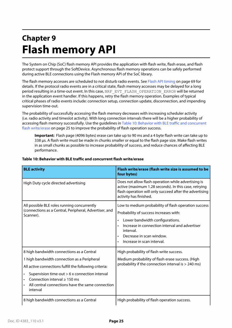
Flash memory APIThe System on Chip (SoC) flash memory API provides the application with flash write, flash erase, and flashprotect support through the SoftDevice. Asynchronous flash memory operations can be safely performedduring active BLE connections using the Flash memory API of the SoC library.
The flash memory accesses are scheduled to not disturb radio events. See Flash API timing on page 69 fordetails. If the protocol radio events are in a critical state, flash memory accesses may be delayed for a longperiod resulting in a time-out event. In this case, NRF_EVT_FLASH_OPERATION_ERROR will be returnedin the application event handler. If this happens, retry the flash memory operation. Examples of typicalcritical phases of radio events include: connection setup, connection update, disconnection, and impendingsupervision time-out.
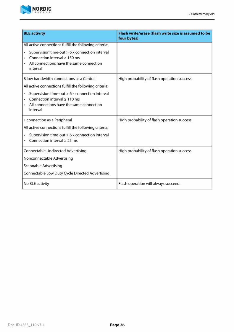
The probability of successfully accessing the flash memory decreases with increasing scheduler activity(i.e. radio activity and timeslot activity). With long connection intervals there will be a higher probability ofaccessing flash memory successfully. Use the guidelines in Table 10: Behavior with BLE traffic and concurrentflash write/erase on page 25 to improve the probability of flash operation success.
Important: Flash page (4096 bytes) erase can take up to 90 ms and a 4 byte flash write can take up to338 µs. A flash write must be made in chunks smaller or equal to the flash page size. Make flash writesin as small chunks as possible to increase probability of success, and reduce chances of affecting BLEperformance.
Table 10: Behavior with BLE traffic and concurrent flash write/erase
BLE activity Flash write/erase (flash write size is assumed to befour bytes)
High Duty cycle directed advertising Does not allow flash operation while advertising isactive (maximum 1.28 seconds). In this case, retryingflash operation will only succeed after the advertisingactivity has finished.
All possible BLE roles running concurrently(connections as a Central, Peripheral, Advertiser, andScanner).
Low to medium probability of flash operation success
Probability of success increases with:
• Lower bandwidth configurations.• Increase in connection interval and advertiser
interval.• Decrease in scan window.• Increase in scan interval.
8 high bandwidth connections as a Central
1 high bandwidth connection as a Peripheral
All active connections fulfill the following criteria:
• Supervision time-out > 6 x connection interval• Connection interval ≥ 150 ms• All central connections have the same connection
interval
High probability of flash write success.
Medium probability of flash erase success. (Highprobability if the connection interval is > 240 ms)
8 high bandwidth connections as a Central High probability of flash operation success.
9 Flash memory API
Doc. ID 4383_110 v3.1 Page 26
BLE activity Flash write/erase (flash write size is assumed to befour bytes)
All active connections fulfill the following criteria:
• Supervision time-out > 6 x connection interval• Connection interval ≥ 150 ms• All connections have the same connection
interval
8 low bandwidth connections as a Central
All active connections fulfill the following criteria:
• Supervision time-out > 6 x connection interval• Connection interval ≥ 110 ms• All connections have the same connection
interval
High probability of flash operation success.
1 connection as a Peripheral
All active connections fulfill the following criteria:
• Supervision time-out > 6 x connection interval• Connection interval ≥ 25 ms
High probability of flash operation success.
Connectable Undirected Advertising
Nonconnectable Advertising
Scannable Advertising
Connectable Low Duty Cycle Directed Advertising
High probability of flash operation success.
No BLE activity Flash operation will always succeed.
Doc. ID 4383_110 v3.1 Page 27
Chapter 10
Multiprotocol supportMultiprotocol support allows a developer to implement their own 2.4 GHz proprietary protocol in theapplication; both when the SoftDevice is not in use (non-concurrent), or while the SoftDevice protocol stackis in use (concurrent). For concurrent multiprotocol implementations, the Radio Timeslot API allows theapplication protocol to safely schedule radio usage between BLE events.
10.1 Non-concurrent multiprotocol implementationFor non-concurrent operation a proprietary 2.4 GHz protocol can be implemented in the application programarea and can access all hardware resources when the SoftDevice is disabled. The SoftDevice may be disabledand enabled without resetting the application in order to switch between a proprietary protocol stack andBluetooth® communication.
10.2 Concurrent multiprotocol implementation using the Radio Timeslot APIThe Radio Timeslot API allows the nRF52 device to be part of a network using the SoftDevice protocol stackand an alternative network of wireless devices at the same time.
The Radio Timeslot (or, simply, Timeslot) feature gives the application access to the radio and other restrictedperipherals during defined time intervals, denoted as timeslots. The Timeslot feature achieves this bycooperatively scheduling the application's use of these peripherals with those of the SoftDevice. Using thisfeature, the application can run other radio protocols (third party custom or proprietary protocols runningfrom application space) concurrently with the internal protocol stack(s) of the SoftDevice. It can also be usedto suppress SoftDevice radio activity and to reserve guaranteed time for application activities with hard timingrequirements, which cannot be met by using the SoC Radio Notifications.
The Timeslot feature is part of the SoC library. The feature works by having the SoftDevice time-multiplexaccess to peripherals between the application and itself. Through the SoC API, the application can open aTimeslot session and request timeslots. When a Timeslot request is granted, the application has exclusive andreal-time access to the normally blocked RADIO, TIMER0, CCM, and AAR peripherals and can use these freelyfor the duration (length) of the timeslot, see Table 3: Hardware access type definitions on page 20 and Table 4:Peripheral protection and usage by SoftDevice on page 20.
10.2.1 Request typesThere are two types of Radio Timeslot requests, earliest possible Timeslot requests and normal Timeslotrequests.
Timeslots may be requested as earliest possible, in which case the timeslot occurs at the first availableopportunity. In the request, the application can limit how far into the future the timeslot may be placed.
Important: The first request in a session must always be earliest possible to create the timing referencepoint for later timeslots.
Timeslots may also be requested at a given time (normal). In this case, the application specifies in the requestwhen the timeslot should start and the time is measured from the start of the previous timeslot.
The application may also request to extend an ongoing timeslot. Extension requests may be repeated,prolonging the timeslot even further.
Timeslots requested as earliest possible are useful for single timeslots and for non-periodic or non-timedactivity. Timeslots requested at a given time relative to the previous timeslot are useful for periodic and timed
10 Multiprotocol support
Doc. ID 4383_110 v3.1 Page 28
activities; for example, a periodic proprietary radio protocol. Timeslot extension may be used to secure asmuch continuous radio time as possible for the application; for example, running an “always on” radio listener.
10.2.2 Request prioritiesRadio Timeslots can be requested at either high or normal priority, indicating how important it is for theapplication to access the specified peripherals. A Timeslot request can only be blocked or cancelled due to anoverlapping SoftDevice activity that has a higher scheduling priority.
10.2.3 Timeslot lengthA Radio Timeslot is requested for a given length. Ongoing timeslots have the possibility to be extended.
The length of the timeslot is specified by the application in the Timeslot request and ranges from 100 μs to100 ms. Longer continuous timeslots can be achieved by requesting to extend the current timeslot. A timeslotmay be extended multiple times, as long as its duration does not extend beyond the time limits set by otherSoftDevice activities, and up to a maximum length of 128 seconds.
10.2.4 SchedulingThe SoftDevice includes a scheduler which manages radio timeslots, priorities and sets up timers to granttimeslots.
Whether a Timeslot request is granted and access to the peripherals is given is determined by the followingfactors:
• The time the request is made,• The exact time in the future the timeslot is requested for,• The desired priority level of the request,• The length of the requested timeslot.
Timeslot API timing on page 69 explains how timeslots are scheduled. Timeslots requested at high prioritywill cancel other activities scheduled at lower priorities in case of a collision. Requests for short timeslots havea higher probability of succeeding than requests for longer timeslots because shorter timeslots are easier to fitinto the schedule.
Important: Radio Notification signals behave the same way for timeslots requested through the RadioTimeslot interface as for SoftDevice internal activities. See section Radio Notification Signals on page43 for more information. If Radio Notifications are enabled, Radio Timeslots will be notified.
10.2.5 High frequency clock configurationThe application can request the SoftDevice to guarantee that the high frequency clock source is set to theexternal crystal and that it is ramped up and stable before the start of the timeslot.
If the application requests the SoftDevice to have the external high frequency crystal ready by the start ofthe timeslot, the SoftDevice will handle all the enabling and disabling of the crystal. The application does notneed to disable the crystal at the end of the timeslot. The SoftDevice will disable the crystal after the end ofthe timeslot unless the SoftDevice needs to use it within a short period of time after the end of the timeslot. Inthat case, the SoftDevice will leave the crystal running.
If the application does not request the SoftDevice to have the external high frequency crystal ready by thestart of the timeslot, then the application must not use the RADIO during the timeslot and must take intoconsideration that the high frequency clock source is inaccurate during the timeslot unless the applicationitself makes sure that the crystal is ramped up and ready at the start of the timeslot. If the application starts thecrystal before or during the timeslot, it is the responsibility of the application to disable it again.
10.2.6 Performance considerationsThe Radio Timeslot API shares core peripherals with the SoftDevice, and application-requested timeslots arescheduled along with other SoftDevice activities. Therefore, the use of the Timeslot feature may influence theperformance of the SoftDevice.
10 Multiprotocol support
Doc. ID 4383_110 v3.1 Page 29
The configuration of the SoftDevice should be considered when using the Radio Timeslot API. A configurationwhich uses more radio time for native protocol operation will reduce the available time for serving timeslotsand result in a higher risk of scheduling conflicts.
All Timeslot requests should use the lowest priority to minimize disturbances to other activities. At this prioritylevel only flash writes might be affected. The high priority should only be used when required, such as forrunning a radio protocol with certain timing requirements that are not met by using normal priority. By usingthe highest priority available to the Timeslot API, non-critical SoftDevice radio protocol traffic may be affected.The SoftDevice radio protocol has access to higher priority levels than the application. These levels will beused for important radio activity, for instance when the device is about to lose a connection.
See Scheduling on page 61 for more information on how priorities work together with other modules likethe BLE protocol stack, the Flash API etc.
Timeslots should be kept as short as possible in order to minimize the impact on the overall performance ofthe device. Requesting a short timeslot will make it easier for the scheduler to fit in between other scheduledactivities. The timeslot may later be extended. This will not affect other sessions as it is only possible to extenda timeslot if the extended time is unreserved.
It is important to ensure that a timeslot has completed its outstanding operations before the time it isscheduled to end (based on its starting time and requested length), otherwise the SoftDevice behavior isundefined and my result in an unrecoverable fault.
10.2.7 Radio Timeslot APIThis section describes the calls, events, signals, and return actions of the Radio Timeslot API.
A Timeslot session is opened and closed using API calls. Within a session, there is an API call to requesttimeslots. For communication back to the application the feature will generate events, which are handled bythe normal application event handler, and signals, which must be handled by a callback function (the signalhandler) provided by the application. The signal handler can also return actions to the SoftDevice. Within atimeslot, only the signal handler is used.
Important: The API calls, events, and signals are only given by their full names in the tables wherethey are listed the first time. Elsewhere, only the last part of the name is used.
10.2.7.1 API callsThese are the API calls defined for the S132 SoftDevice:
Table 11: API calls
API call Description
sd_radio_session_open() Open a radio timeslot session.
sd_radio_session_close() Close a radio timeslot session.
sd_radio_request() Request a radio timeslot.
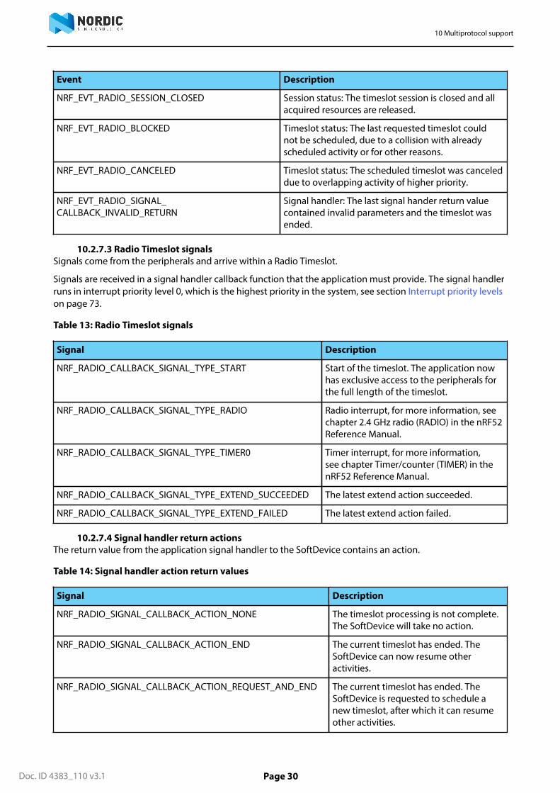
10.2.7.2 Radio Timeslot eventsEvents come from the SoftDevice scheduler and are used for Radio Timeslot session management.
Events are received in the application event handler callback function, which will typically be run in anapplication interrupt, see Events - SoftDevice to application on page 12. The following events are defined:
Table 12: Radio Timeslot events
Event Description
NRF_EVT_RADIO_SESSION_IDLE Session status: The current timeslot session has noremaining scheduled timeslots.
10 Multiprotocol support
Doc. ID 4383_110 v3.1 Page 30
Event Description
NRF_EVT_RADIO_SESSION_CLOSED Session status: The timeslot session is closed and allacquired resources are released.
NRF_EVT_RADIO_BLOCKED Timeslot status: The last requested timeslot couldnot be scheduled, due to a collision with alreadyscheduled activity or for other reasons.
NRF_EVT_RADIO_CANCELED Timeslot status: The scheduled timeslot was canceleddue to overlapping activity of higher priority.
NRF_EVT_RADIO_SIGNAL_CALLBACK_INVALID_RETURN
Signal handler: The last signal hander return valuecontained invalid parameters and the timeslot wasended.
10.2.7.3 Radio Timeslot signalsSignals come from the peripherals and arrive within a Radio Timeslot.
Signals are received in a signal handler callback function that the application must provide. The signal handlerruns in interrupt priority level 0, which is the highest priority in the system, see section Interrupt priority levelson page 73.
Table 13: Radio Timeslot signals
Signal Description
NRF_RADIO_CALLBACK_SIGNAL_TYPE_START Start of the timeslot. The application nowhas exclusive access to the peripherals forthe full length of the timeslot.
NRF_RADIO_CALLBACK_SIGNAL_TYPE_RADIO Radio interrupt, for more information, seechapter 2.4 GHz radio (RADIO) in the nRF52Reference Manual.
NRF_RADIO_CALLBACK_SIGNAL_TYPE_TIMER0 Timer interrupt, for more information,see chapter Timer/counter (TIMER) in thenRF52 Reference Manual.
NRF_RADIO_CALLBACK_SIGNAL_TYPE_EXTEND_SUCCEEDED The latest extend action succeeded.
NRF_RADIO_CALLBACK_SIGNAL_TYPE_EXTEND_FAILED The latest extend action failed.
10.2.7.4 Signal handler return actionsThe return value from the application signal handler to the SoftDevice contains an action.
Table 14: Signal handler action return values
Signal Description
NRF_RADIO_SIGNAL_CALLBACK_ACTION_NONE The timeslot processing is not complete.The SoftDevice will take no action.
NRF_RADIO_SIGNAL_CALLBACK_ACTION_END The current timeslot has ended. TheSoftDevice can now resume otheractivities.
NRF_RADIO_SIGNAL_CALLBACK_ACTION_REQUEST_AND_END The current timeslot has ended. TheSoftDevice is requested to schedule anew timeslot, after which it can resumeother activities.

10 Multiprotocol support
Doc. ID 4383_110 v3.1 Page 31
Signal Description
NRF_RADIO_SIGNAL_CALLBACK_ACTION_EXTEND The SoftDevice is requested to extendthe ongoing timeslot.
10.2.7.5 Ending a timeslot in timeThe application is responsible for keeping track of timing within the Radio Timeslot and for ensuring that theapplication’s use of the peripherals does not last for longer than the granted timeslot length.
For these purposes, the application is granted access to the TIMER0 peripheral for the length of the timeslot.This timer is started from zero by the SoftDevice at the start of the timeslot, and is configured to run at 1 MHz.The recommended practice is to set up a timer interrupt that expires before the timeslot expires, with enoughtime left of the timeslot to do any clean-up actions before the timeslot ends. Such a timer interrupt can also beused to request an extension of the timeslot, but there must still be enough time to clean up if the extension isnot granted.
Important: The scheduler uses the low frequency clock source for time calculations when schedulingevents. If the application uses a TIMER (sourced from the current high frequency clock source) tocalculate and signal the end of a timeslot, it must account for the possible clock drift between the highfrequency clock source and the low frequency clock source.
10.2.7.6 The signal handler runs at interrupt priority level 0The signal handler runs at interrupt priority level 0, which is the highest priority. Therefore, it cannot beinterrupted by any other activity.
Since the signal handler runs at a higher interrupt priority (lower numerical value for the priority level) thanthe SVC calls (see Interrupt priority levels on page 73), SVC calls are not available in the signal handler.
Important: It is a requirement that processing in the signal handler does not exceed the grantedtime of the timeslot. If it does, the behavior of the SoftDevice is undefined and the SoftDevice maymalfunction.
The signal handler may be called several times during a timeslot. It is recommended to use the signal handleronly for real time signal handling. When the application has handled the signal, it can exit the signal handlerand wait for the next signal, if it wants to do other (less time critical) processing at lower interrupt priority(higher numerical value for the priority level) while waiting.
10.3 Radio Timeslot API usage scenariosIn this section several Radio Timeslot API usage scenarios are provided with descriptions of the sequence ofevents within them.
10.3.1 Complete session exampleThis section describes a complete Radio Timeslot session.
Figure 3: Complete Radio Timeslot session example on page 32 shows a complete Timeslot session. In thiscase, only timeslot requests from the application are being scheduled, there is no SoftDevice activity.
At start, the application calls the API to open a session and to request a first timeslot (which must be of typeearliest possible). The SoftDevice schedules the timeslot. At the start of the timeslot, the SoftDevice calls theapplication signal hander with the START signal. After this, the application is in control and has access to theperipherals. The application will then typically set up TIMER0 to expire before the end of the timeslot, to geta signal indicating that the timeslot is about to end. In the last signal in the timeslot, the application uses thesignal handler return action to request a new timeslot 100 ms after the first.
All subsequent timeslots are similar (see the middle timeslot in Figure 3: Complete Radio Timeslot sessionexample on page 32). The signal handler is called with the START signal at the start of the timeslot.The application then has control, but must arrange for a signal to come towards the end of the timeslot.

10 Multiprotocol support
Doc. ID 4383_110 v3.1 Page 32
As the return value for the last signal in the timeslot, the signal handler requests a new timeslot using theREQUEST_AND_END action.
Eventually, the application does not require the radio any more. So, at the last signal in the last timeslot (Figure3: Complete Radio Timeslot session example on page 32), the application returns END from the signalhandler. The SoftDevice then sends an IDLE event to the application event handler. The application callssession_close, and the SoftDevice sends the CLOSED event. The session has now ended.
Main
Event handler (App(L))
Signal handler (LowerStack)
Timeslot API
Timeslots
sess
ion_
open
()
requ
est (
earli
est,
leng
th =
10
ms)
sign
al: S
TAR
T
< . .
. . >
actio
n: R
EQ
UE
ST_
AN
D_E
ND
pa
ram
eter
s: d
ista
nce
= 10
0 m
s,
leng
th =
5 m
s
< . .
. . >
actio
n: R
EQ
UE
ST_
AN
D_E
ND
pa
ram
eter
s: d
ista
nce
= 50
ms,
le
ngth
= 1
0 m
s
< . .
. . >
actio
n: E
ND
even
t: ID
LE
sess
ion_
clos
e()
even
t: C
LOS
ED
actio
n: N
ON
E
10 ms
100 ms
5 ms
50 ms
10 ms
sign
al: S
TAR
T
actio
n: N
ON
E
sign
al: S
TAR
T
actio
n: N
ON
E
Figure 3: Complete Radio Timeslot session example
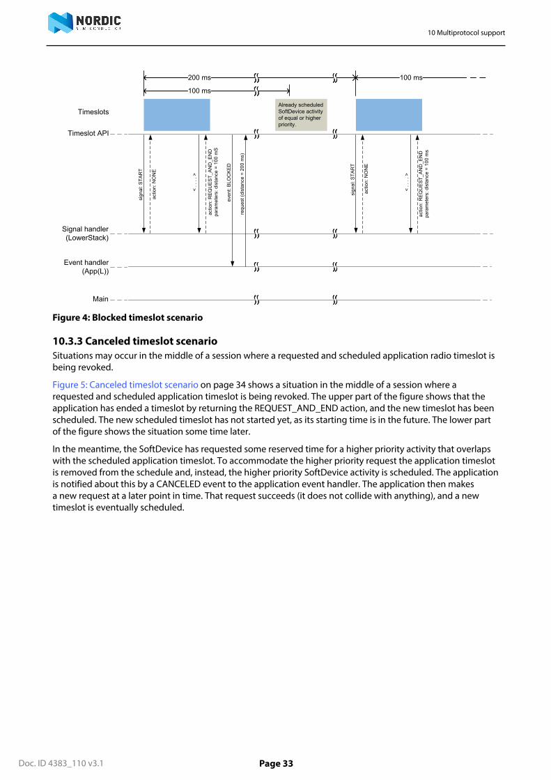
10.3.2 Blocked timeslot scenarioRadio Timeslot requests may be blocked due to an overlap with activities already scheduled by the SoftDevice.
Figure 4: Blocked timeslot scenario on page 33 shows a situation in the middle of a session where arequested timeslot cannot be scheduled. At the end of the first timeslot illustrated here, the applicationsignal handler returns a REQUEST_AND_END action to request a new timeslot. The new timeslot cannot bescheduled as requested, because of a collision with an already scheduled SoftDevice activity. The applicationis notified about this by a BLOCKED event to the application event handler. The application then makes a newrequest for a later point in time. This request succeeds (it does not collide with anything), and a new timeslot iseventually scheduled.
10 Multiprotocol support
Doc. ID 4383_110 v3.1 Page 33
Main
Event handler (App(L))
Signal handler (LowerStack)
Timeslot API
Timeslots
sign
al: S
TAR
T
< . .
. . >
actio
n: R
EQ
UE
ST_
AN
D_E
ND
pa
ram
eter
s: d
ista
nce
= 10
0 m
S
< . .
. . >
actio
n: R
EQ
UE
ST_
AN
D_E
ND
pa
ram
eter
s: d
ista
nce
= 10
0 m
s
even
t: B
LOC
KE
D
requ
est (
dist
ance
= 2
00 m
s)
actio
n: N
ON
E
200 ms
Already scheduled SoftDevice activity of equal or higher priority.
sign
al: S
TAR
T
actio
n: N
ON
E
100 ms
100 ms
Figure 4: Blocked timeslot scenario
10.3.3 Canceled timeslot scenarioSituations may occur in the middle of a session where a requested and scheduled application radio timeslot isbeing revoked.
Figure 5: Canceled timeslot scenario on page 34 shows a situation in the middle of a session where arequested and scheduled application timeslot is being revoked. The upper part of the figure shows that theapplication has ended a timeslot by returning the REQUEST_AND_END action, and the new timeslot has beenscheduled. The new scheduled timeslot has not started yet, as its starting time is in the future. The lower partof the figure shows the situation some time later.
In the meantime, the SoftDevice has requested some reserved time for a higher priority activity that overlapswith the scheduled application timeslot. To accommodate the higher priority request the application timeslotis removed from the schedule and, instead, the higher priority SoftDevice activity is scheduled. The applicationis notified about this by a CANCELED event to the application event handler. The application then makesa new request at a later point in time. That request succeeds (it does not collide with anything), and a newtimeslot is eventually scheduled.

10 Multiprotocol support
Doc. ID 4383_110 v3.1 Page 34
Main
Event handler (App(L))
Signal handler (LowerStack)
Timeslot API
Timeslots
sign
al: S
TAR
T
< . .
. . >
actio
n: R
EQ
UE
ST_
AN
D_E
ND
pa
ram
eter
s: d
ista
nce
= 10
0 m
S
100 ms
Scheduled future timeslot
10 ms
Main
Event handler (App(L))
Signal handler (LowerStack)
Timeslot API
Timeslots
sign
al: S
TAR
T
< . .
. . >
actio
n: R
EQ
UE
ST_
AN
D_E
ND
pa
ram
eter
s: d
ista
nce
= 10
0 m
S
< . .
. . >
actio
n: R
EQ
UE
ST_
AN
D_E
ND
pa
ram
eter
s: d
ista
nce
= 10
0 m
s
even
t: C
AN
CE
LED
requ
est (
dist
ance
= 2
00 m
s)
200 ms
Higher priority activity arriving later
sign
al: S
TAR
T
actio
n: N
ON
E
100 ms
100 ms
Figure 5: Canceled timeslot scenario
10.3.4 Radio Timeslot extension exampleAn application can use Radio Timeslot extension to create long continuous timeslots that will give theapplication as much radio time as possible while disturbing the SoftDevice activities as little as possible.
In the first timeslot in Figure 6: Radio Timeslot extension example on page 35 the application uses thesignal handler return action to request an extension of the timeslot. The extension is granted, and the timeslotis seamlessly prolonged. The second attempt to extend the timeslot fails, as a further extension would cause acollision with a SoftDevice activity that has been scheduled. Therefore, the application makes a new request,of type earliest. This results in a new Radio Timeslot being scheduled immediately after the SoftDevice activity.This new timeslot can be extended a number of times.

10 Multiprotocol support
Doc. ID 4383_110 v3.1 Page 35
Main
Event handler (App(L))
Signal handler (LowerStack)
Timeslot API
Timeslots
sign
al: S
TAR
T
< . .
. . >
actio
n: E
XTE
ND
pa
ram
eter
s: le
ngth
= 1
0 m
s
actio
n: N
ON
E
Other scheduled activity
10 ms
sign
al: E
XTE
ND
_SU
CC
ED
ED
actio
n: N
ON
E
10 ms
< . .
. . >
actio
n: E
XTE
ND
pa
ram
eter
s: le
ngth
= 1
0 m
ssi
gnal
: EX
TEN
D_F
AIL
ED
actio
n: R
EQ
UE
ST_
AN
D_E
ND
pa
ram
eter
s: e
arlie
st, l
engt
h =
10 m
s
10 ms
sign
al: S
TAR
T
< . .
. . >
actio
n: E
XTE
ND
pa
ram
eter
s: le
ngth
= 1
0 m
s
actio
n: N
ON
E
sign
al: E
XTE
ND
_SU
CC
ED
ED
actio
n: N
ON
E
10 ms
Figure 6: Radio Timeslot extension example

Doc. ID 4383_110 v3.1 Page 36
Chapter 11
Bluetooth® low energy protocolstackThe Bluetooth® 4.2 compliant low energy Host and Controller implemented by the SoftDevice are fullyqualified with multi-role support (Central, Observer, Peripheral, and Broadcaster).
The SoftDevice allows applications to implement standard Bluetooth® low energy profiles as well asproprietary use case implementations. The API is defined above the Generic Attribute Protocol (GATT), GenericAccess Profile (GAP), and Logical Link Control and Adaptation Protocol (L2CAP).
The nRF5 Software Development Kit (nRF5 SDK) complements the SoftDevice with Service and Profileimplementations. Single-mode System on Chip (SoC) applications are enabled by the full BLE protocol stackand nRF52 Series SoC.
nRF5x SoC
SoftDevice
Host
Controller
Physical Layer (PHY)
Generic Attribute Profile (GATT)
Attribute Protocol (ATT)
Logical Link Control and Adaptation Layer Protocol (L2CAP)
Link Layer (LL)
Security Manager (SM)
Generic Access Profile(GAP)
ApplicationProfiles and Services
Figure 7: SoftDevice stack architecture
11.1 Profile and service supportThis section lists the profiles and services adopted by the Bluetooth Special Interest Group at the time ofpublication of this document.
The SoftDevice supports all profiles and services (with exceptions as noted in Table 15: Supported profiles andservices on page 36) as well as additional proprietary profiles.
Table 15: Supported profiles and services
Adopted profile Adopted services
HID over GATT HID
Battery
Device Information

11 Bluetooth® low energy protocol stack
Doc. ID 4383_110 v3.1 Page 37
Adopted profile Adopted services
Heart Rate Heart Rate
Device Information
Proximity Link Loss
Immediate Alert
Tx Power
Blood Pressure Blood Pressure
Device Information
Health Thermometer Health Thermometer
Device Information
Glucose Glucose
Device Information
Phone Alert Status Phone Alert Status
Alert Notification Alert Notification
Time Current Time
Next DST Change
Reference Time Update
Find Me Immediate Alert
Cycling Speed and Cadence Cycling Speed and Cadence
Device Information
Running Speed and Cadence Running Speed and Cadence
Device Information
Location and Navigation Location and Navigation
Cycling Power Cycling Power
Scan Parameters Scan Parameters
Weight Scale Weight Scale
Body Composition
User Data
Device Information
Continuous Glucose Monitoring Continuous Glucose Monitoring
Bond Management
Device Information
Environmental Sensing Environmental Sensing

11 Bluetooth® low energy protocol stack
Doc. ID 4383_110 v3.1 Page 38
Adopted profile Adopted services
Pulse Oximeter Pulse Oximeter
Device Information
Bond Management
Battery
Current Time
Object Transfer
(Currently not supported by the SoftDevice)
Object Transfer
Automation IO Automation IO
Indoor Positioning
Internet Protocol Support
(Currently not supported by the SoftDevice)
Important: Examples for selected profiles and services are available in the nRF5 SDK. See the nRF5SDK documentation for details.
11.2 Bluetooth® low energy featuresThe BLE protocol stack in the SoftDevice has been designed to provide an abstract but flexible interface forapplication development for Bluetooth® low energy devices.
GAP, GATT, SM, and L2CAP are implemented in the SoftDevice and managed through the API. The SoftDeviceimplements GAP and GATT procedures and modes that are common to most profiles such as the handling ofdiscovery, connection, data transfer, and bonding.
The BLE API is consistent across Bluetooth® role implementations where common features have the sameinterface. The following tables describe the features found in the BLE protocol stack.
Table 16: API features in the BLE stack
API features Description
Interface to:
GATT / GAP
Consistency between APIs including shared dataformats.
Attribute table sizing, population and access Full flexibility to size the attribute table at applicationcompile time and to populate it at run time. Attributeremoval is not supported.
Asynchronous and event driven Thread-safe function and event model enforced bythe architecture.
Vendor-specific (128-bit) UUIDs for proprietaryprofiles
Compact, fast and memory efficient management of128-bit UUIDs.
Packet flow control Full application control over data buffers to ensuremaximum throughput.

11 Bluetooth® low energy protocol stack
Doc. ID 4383_110 v3.1 Page 39
Table 17: GAP features in the BLE stack
GAP features Description
Multi-role: Central, Peripheral, Observer, and Broadcaster canrun concurrently with a connection.
Multiple bond support Keys and peer information stored in applicationspace.
No restrictions in stack implementation.
Security Mode 1:
Levels 1, 2, 3 & 4
Support for all levels of SM 1.
Table 18: GATT features in the BLE stack
GATT features Description
Full GATT Server Support for eight concurrent ATT server sessions.Includes configurable Service Changed support.
Support for authorization Enables control points.
Enables freshest data.
Enables GAP authorization.
Full GATT Client Flexible data management options for packettransmission with either fine control or abstractmanagement.
Implemented GATT Sub-procedures Exchange MTU.
Discover all Primary Services.
Discover Primary Service by Service UUID.
Find included Services.
Discover All Characteristics of a Service.
Discover Characteristics by UUID.
Discover All Characteristic Descriptors.
Read Characteristic Value.
Read using Characteristic UUID.
Read Long Characteristic Values.
Read Multiple Characteristic Values (Client only).
Write Without Response.
Write Characteristic Value.
Notifications.
Indications.
Read Characteristic Descriptors.
Read Long Characteristic Descriptors.

11 Bluetooth® low energy protocol stack
Doc. ID 4383_110 v3.1 Page 40
GATT features Description
Write Characteristic Descriptors.
Write Long Characteristic Values.
Write Long Characteristic Descriptors.
Reliable Writes.
Table 19: Security Manager (SM) features in the BLE stack
Security Manager features Description
Flexible key generation and storage for reducedmemory requirements.
Keys are stored directly in application memory toavoid unnecessary copies and memory constraints.
Authenticated MITM (Man in the middle) protection Allows for per-link elevation of the encryptionsecurity level.
Pairing methods:
Just works, Numeric Comparison, Passkey Entry andOut of Band
API provides the application full control of the pairingsequences.
Table 20: Attribute Protocol (ATT) features in the BLE stack
ATT features Description
Server protocol Fast and memory efficient implementation of the ATTserver role.
Client protocol Fast and memory efficient implementation of the ATTclient role.
Configurable ATT_MTU size Allows for per-link configuration of ATT_MTU size.
Table 21: Controller, Link Layer (LL) features in the BLE stack
Controller, Link Layer features Description
Master role
Scanner/Initiator roles
The SoftDevice supports eight concurrent masterconnections and an additional Scanner/Initiatorrole. When the maximum number of simultaneousconnections are established, the Scanner role will besupported for new device discovery. However, theInitiator is not available at that time.
Channel map configuration Setup of channel map for all master connectionsfrom the application.
Accepting update for the channel map for a slaveconnection.
Slave role
Advertiser/broadcaster role
Supports Advertiser, or one peripheral connectionand one additional Broadcaster.
Master-initiated connection parameter update Central role may initiate connection parameterupdate. Peripheral role will accept connectionparameter update.
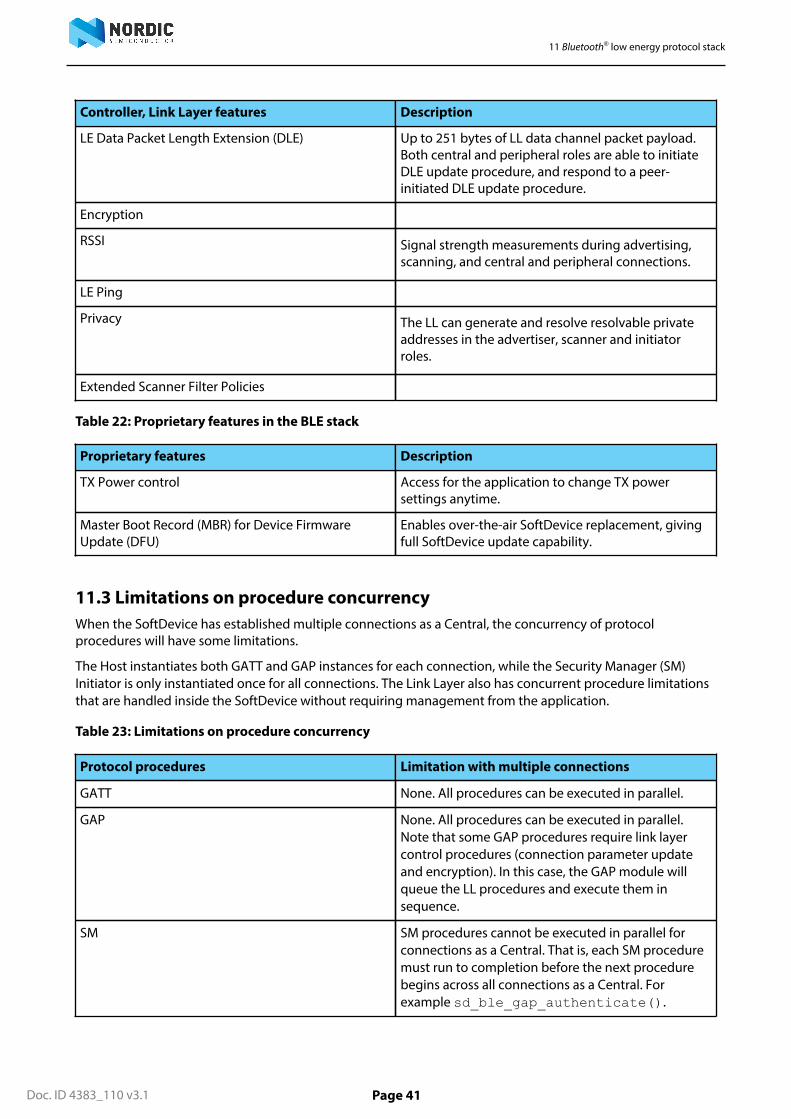
11 Bluetooth® low energy protocol stack
Doc. ID 4383_110 v3.1 Page 41
Controller, Link Layer features Description
LE Data Packet Length Extension (DLE) Up to 251 bytes of LL data channel packet payload.Both central and peripheral roles are able to initiateDLE update procedure, and respond to a peer-initiated DLE update procedure.
Encryption
RSSI Signal strength measurements during advertising,scanning, and central and peripheral connections.
LE Ping
Privacy The LL can generate and resolve resolvable privateaddresses in the advertiser, scanner and initiatorroles.
Extended Scanner Filter Policies
Table 22: Proprietary features in the BLE stack
Proprietary features Description
TX Power control Access for the application to change TX powersettings anytime.
Master Boot Record (MBR) for Device FirmwareUpdate (DFU)
Enables over-the-air SoftDevice replacement, givingfull SoftDevice update capability.
11.3 Limitations on procedure concurrencyWhen the SoftDevice has established multiple connections as a Central, the concurrency of protocolprocedures will have some limitations.
The Host instantiates both GATT and GAP instances for each connection, while the Security Manager (SM)Initiator is only instantiated once for all connections. The Link Layer also has concurrent procedure limitationsthat are handled inside the SoftDevice without requiring management from the application.
Table 23: Limitations on procedure concurrency
Protocol procedures Limitation with multiple connections
GATT None. All procedures can be executed in parallel.
GAP None. All procedures can be executed in parallel.Note that some GAP procedures require link layercontrol procedures (connection parameter updateand encryption). In this case, the GAP module willqueue the LL procedures and execute them insequence.
SM SM procedures cannot be executed in parallel forconnections as a Central. That is, each SM proceduremust run to completion before the next procedurebegins across all connections as a Central. Forexample sd_ble_gap_authenticate().
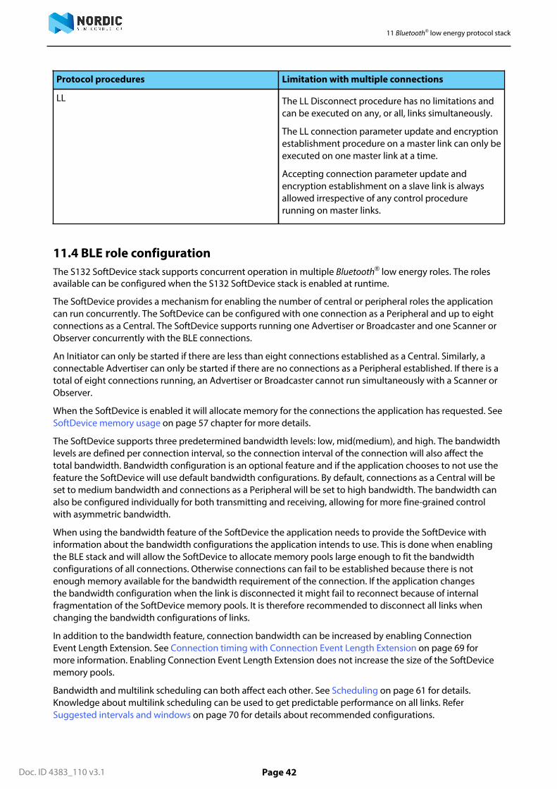
11 Bluetooth® low energy protocol stack
Doc. ID 4383_110 v3.1 Page 42
Protocol procedures Limitation with multiple connections
LL The LL Disconnect procedure has no limitations andcan be executed on any, or all, links simultaneously.
The LL connection parameter update and encryptionestablishment procedure on a master link can only beexecuted on one master link at a time.
Accepting connection parameter update andencryption establishment on a slave link is alwaysallowed irrespective of any control procedurerunning on master links.
11.4 BLE role configurationThe S132 SoftDevice stack supports concurrent operation in multiple Bluetooth® low energy roles. The rolesavailable can be configured when the S132 SoftDevice stack is enabled at runtime.
The SoftDevice provides a mechanism for enabling the number of central or peripheral roles the applicationcan run concurrently. The SoftDevice can be configured with one connection as a Peripheral and up to eightconnections as a Central. The SoftDevice supports running one Advertiser or Broadcaster and one Scanner orObserver concurrently with the BLE connections.
An Initiator can only be started if there are less than eight connections established as a Central. Similarly, aconnectable Advertiser can only be started if there are no connections as a Peripheral established. If there is atotal of eight connections running, an Advertiser or Broadcaster cannot run simultaneously with a Scanner orObserver.
When the SoftDevice is enabled it will allocate memory for the connections the application has requested. SeeSoftDevice memory usage on page 57 chapter for more details.
The SoftDevice supports three predetermined bandwidth levels: low, mid(medium), and high. The bandwidthlevels are defined per connection interval, so the connection interval of the connection will also affect thetotal bandwidth. Bandwidth configuration is an optional feature and if the application chooses to not use thefeature the SoftDevice will use default bandwidth configurations. By default, connections as a Central will beset to medium bandwidth and connections as a Peripheral will be set to high bandwidth. The bandwidth canalso be configured individually for both transmitting and receiving, allowing for more fine-grained controlwith asymmetric bandwidth.
When using the bandwidth feature of the SoftDevice the application needs to provide the SoftDevice withinformation about the bandwidth configurations the application intends to use. This is done when enablingthe BLE stack and will allow the SoftDevice to allocate memory pools large enough to fit the bandwidthconfigurations of all connections. Otherwise connections can fail to be established because there is notenough memory available for the bandwidth requirement of the connection. If the application changesthe bandwidth configuration when the link is disconnected it might fail to reconnect because of internalfragmentation of the SoftDevice memory pools. It is therefore recommended to disconnect all links whenchanging the bandwidth configurations of links.
In addition to the bandwidth feature, connection bandwidth can be increased by enabling ConnectionEvent Length Extension. See Connection timing with Connection Event Length Extension on page 69 formore information. Enabling Connection Event Length Extension does not increase the size of the SoftDevicememory pools.
Bandwidth and multilink scheduling can both affect each other. See Scheduling on page 61 for details.Knowledge about multilink scheduling can be used to get predictable performance on all links. ReferSuggested intervals and windows on page 70 for details about recommended configurations.

Doc. ID 4383_110 v3.1 Page 43
Chapter 12
Radio NotificationThe Radio Notification is a configurable feature that enables ACTIVE and INACTIVE (nACTIVE) signals from theSoftDevice to the application notifying it when the radio is in use.
12.1 Radio Notification SignalsThe Radio Notification signals are sent prior to and at the end of SoftDevice Radio Events or application RadioEvents 10, i.e. defined time intervals of radio operation.
Radio notifications behave differently when Connection Event Length Extension is enabled. Radio Notificationwith Connection Event Length Extension on page 50 explains the behavior when this feature is enabled.Otherwise the presented material assumes that the feature is disabled.
To ensure that the Radio Notification signals behave in a consistent way, the Radio Notification shall alwaysbe configured when the SoftDevice is in an idle state with no protocol stack or other SoftDevice activity inprogress. Therefore, it is recommended to configure the Radio Notification signals directly after the SoftDevicehas been enabled.
If it is enabled, the ACTIVE signal is sent before the Radio Event starts. Similarly, if the nACTIVE signal isenabled, it is sent at the end of the Radio Event. These signals can be used by the application developer tosynchronize the application logic with the radio activity. For example, the ACTIVE signal can be used to switchoff external devices to manage peak current drawn during periods when the radio is ON, or to trigger sensordata collection for transmission during the upcoming Radio Event.
The notification signals are sent using software interrupt, as specified in Table 5: Allocation of softwareinterrupt vectors to SoftDevice signals on page 22.
As both ACTIVE and nACTIVE use the same software interrupt, it is up to the application to manage them. Ifboth ACTIVE and nACTIVE are configured ON by the application, there will always be an ACTIVE signal beforean nACTIVE signal.
Refer to Table 24: Notation and terminology for the Radio Notification used in this chapter on page 44 forthe notation that is used in this Section.
When there is sufficient time between Radio Events (tgap > tndist), both the ACTIVE and nACTIVE notificationsignals will be present at each Radio Event. Figure 8: Two radio events with ACTIVE and nACTIVE signals onpage 44 illustrates an example of this scenario with two Radio Events. The figure also illustrates the ACTIVEand nACTIVE signals with respect to the Radio Events.
When there is not sufficient time between the Radio Events (tgap < tndist), the ACTIVE and nACTIVE notificationsignals will be skipped. There will still be an ACTIVE signal before the first event, and an nACTIVE signal afterthe last event. This is shown in Figure 9: Two radio events where tgap is too small and the notification signalswill not be available between the events on page 44.
10 Application Radio Events are defined as Radio Timeslots, see Multiprotocol support on page 27.
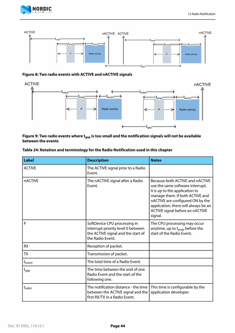
12 Radio Notification
Doc. ID 4383_110 v3.1 Page 44
ACTIVE
P
tndist
Radio activity
tprep tevent
nACTIVE
P
tndist
Radio activity
tprep tevent
tgap
ACTIVEnACTIVE
Figure 8: Two radio events with ACTIVE and nACTIVE signals
ACTIVE
P
tndist
Radio activity
tprep tevent
nACTIVE
P Radio activity
tprep tevent
tgap
tndist
Figure 9: Two radio events where tgap is too small and the notification signals will not be availablebetween the events
Table 24: Notation and terminology for the Radio Notification used in this chapter
Label Description Notes
ACTIVE The ACTIVE signal prior to a RadioEvent.
nACTIVE The nACTIVE signal after a RadioEvent.
Because both ACTIVE and nACTIVEuse the same software interrupt,it is up to the application tomanage them. If both ACTIVE andnACTIVE are configured ON by theapplication, there will always be anACTIVE signal before an nACTIVEsignal.
P SoftDevice CPU processing ininterrupt priority level 0 betweenthe ACTIVE signal and the start ofthe Radio Event.
The CPU processing may occuranytime, up to tprep before thestart of the Radio Event.
RX Reception of packet.
TX Transmission of packet.
tevent The total time of a Radio Event.
tgap The time between the end of oneRadio Event and the start of thefollowing one.
tndist The notification distance - the timebetween the ACTIVE signal and thefirst RX/TX in a Radio Event.
This time is configurable by theapplication developer.

12 Radio Notification
Doc. ID 4383_110 v3.1 Page 45
Label Description Notes
tprep The time before first RX/TXavailable to the protocol stack toprepare and configure the radio.
The application will be interruptedby a SoftDevice interrupt handlerat priority level 0 tprep time unitsbefore the start of the Radio Event.
Important: All packetdata to send in an eventshould have been sent tothe stack tprep before theRadio Event starts.
tP Time used for preprocessingbefore the Radio Event.
tinterval Time period of periodic protocolRadio Events (e.g. BLE connectioninterval).
tEEO Minimum time between centralrole Radio Events (Event-to-EventOffset).
The minimum time between thestart of adjacent central role Radioevents, and between the lastcentral role radio event and thescanner. tEEO-C0 can be differentfor different connections, and itdepends on the maximum packetpayload size and the bandwidthconfiguration of the connection.See BLE role configuration on page42 for more information on the BLEstack configuration. ConnectionEvent Length Extension does notaffect tEEO.
tScanReserved Reserved time needed by theSoftDevice for each ScanWindow
Table 25: BLE Radio Notification timing ranges
Value Range (μs)
tndist 800, 1740, 2680, 3620, 4560, 5500 (Configured by theapplication)
tevent 2750 to 5500 - Undirected and scannable advertising,0 to 31 byte payload, 3 channels
2150 to 2950 - Non-connectable advertising, 0 to 31byte payload, 3 channels
1.28 seconds - Directed advertising, 3 channels
Slave bandwidth LOW : 1700
Slave bandwidth MID : 3650
Slave bandwidth HIGH : 6550
Master bandwidth LOW : 1575
Master bandwidth MID : 3500
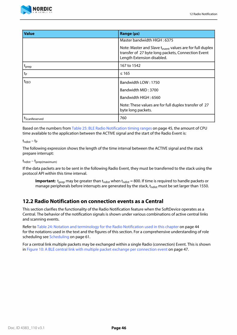
12 Radio Notification
Doc. ID 4383_110 v3.1 Page 46
Value Range (μs)
Master bandwidth HIGH : 6375
Note: Master and Slave tevent values are for full duplextransfer of 27 byte long packets, Connection EventLength Extension disabled.
tprep 167 to 1542
tP ≤ 165
tEEO Bandwidth LOW : 1750
Bandwidth MID : 3700
Bandwidth HIGH : 6560
Note: These values are for full duplex transfer of 27byte long packets.
tScanReserved 760
Based on the numbers from Table 25: BLE Radio Notification timing ranges on page 45, the amount of CPUtime available to the application between the ACTIVE signal and the start of the Radio Event is:
tndist – tP
The following expression shows the length of the time interval between the ACTIVE signal and the stackprepare interrupt:
tndist – tprep(maximum)
If the data packets are to be sent in the following Radio Event, they must be transferred to the stack using theprotocol API within this time interval.
Important: tprep may be greater than tndist when tndist = 800. If time is required to handle packets ormanage peripherals before interrupts are generated by the stack, tndist must be set larger than 1550.
12.2 Radio Notification on connection events as a CentralThis section clarifies the functionality of the Radio Notification feature when the SoftDevice operates as aCentral. The behavior of the notification signals is shown under various combinations of active central linksand scanning events.
Refer to Table 24: Notation and terminology for the Radio Notification used in this chapter on page 44for the notations used in the text and the figures of this section. For a comprehensive understanding of rolescheduling see Scheduling on page 61.
For a central link multiple packets may be exchanged within a single Radio (connection) Event. This is shownin Figure 10: A BLE central link with multiple packet exchange per connection event on page 47.

12 Radio Notification
Doc. ID 4383_110 v3.1 Page 47
TX
RX
ACTIVE
P TX
RX
TX
RX
nACTIVE
tinterval
tevent
tP
tprep
tndist
Figure 10: A BLE central link with multiple packet exchange per connection event
RX
TX
ACTIVE
P
tndist tprep
tinterval
ACTIVE
tndist
nACTIVE
tevent
RX
TXP
tprep tevent
tEEOLink-0 Link-0
nACTIVE
tprep
Figure 11: BLE Radio Notification signal in relation to a single active link
To ensure that the ACTIVE notification signal will be available to the application at the configured time whena single central link is established (Figure 11: BLE Radio Notification signal in relation to a single active link onpage 47), the following condition must hold:
tndist + tEEO -tprep < tinterval
RX
TX
ACTIVE
P
tndisttprep
tinterval
ACTIVE nACTIVE
tevent
tEEO,0
Link-0
RX
TXP
Link-1
teventtprep
RX
TXP
tevent
Link-2
tprep
tEEO,1 tEEO,2
RX
TXP
tndisttprep tevent
Link-0
RX
TXP
Link-1
teventtprep
nACTIVE
tprep
Figure 12: BLE Radio Notification signal in relation to 3 active links
A SoftDevice operating as a Central may establish multiple central links and schedule them back-to-back ineach connection interval. An example of a Central with 3 links is shown in Figure 12: BLE Radio Notificationsignal in relation to 3 active links on page 47). To ensure that the ACTIVE notification signal will be availableto the application at the configured time when 3 links are established as a Central, the following conditionmust hold:
tndist +tEEO,0 +tEEO,1 +tEEO,2 -tprep < tinterval
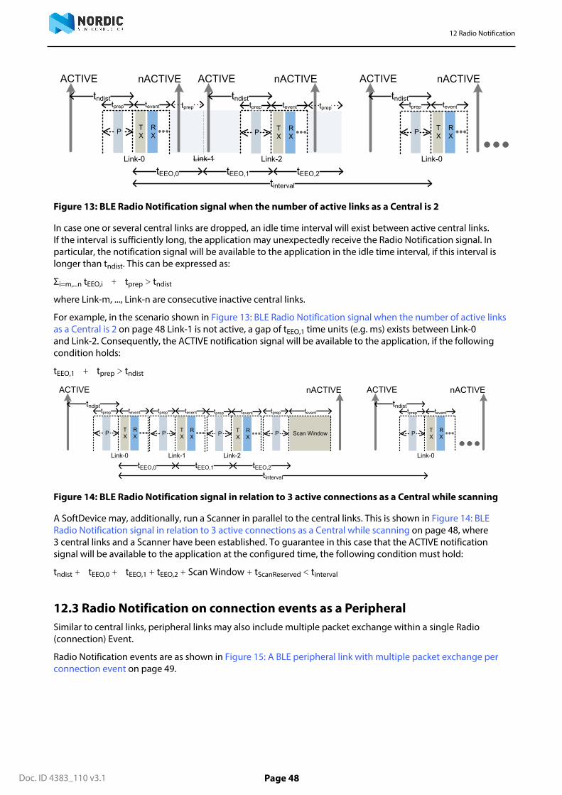
12 Radio Notification
Doc. ID 4383_110 v3.1 Page 48
ACTIVE
RX
TX
ACTIVE
P
tndisttprep
tinterval
ACTIVE nACTIVE
tevent
tEEO,0
Link-0
RX
TXP
tevent
Link-2
tndisttprep
tEEO,1 tEEO,2
RX
TXP
tndisttprep tevent
Link-0
nACTIVE
Link-1
nACTIVE
tpreptprep
Figure 13: BLE Radio Notification signal when the number of active links as a Central is 2
In case one or several central links are dropped, an idle time interval will exist between active central links.If the interval is sufficiently long, the application may unexpectedly receive the Radio Notification signal. Inparticular, the notification signal will be available to the application in the idle time interval, if this interval islonger than tndist. This can be expressed as:
Σi=m,...n tEEO,i + tprep > tndist
where Link-m, ..., Link-n are consecutive inactive central links.
For example, in the scenario shown in Figure 13: BLE Radio Notification signal when the number of active linksas a Central is 2 on page 48 Link-1 is not active, a gap of tEEO,1 time units (e.g. ms) exists between Link-0and Link-2. Consequently, the ACTIVE notification signal will be available to the application, if the followingcondition holds:
tEEO,1 + tprep > tndist
RX
TX
ACTIVE
P
tndisttprep
nACTIVE
tinterval
ACTIVE nACTIVE
tevent
tEEO,0
Link-0
RX
TXP
Link-1
teventtprep
RX
TXP
tevent
Link-2
tprep
tEEO,1 tEEO,2
RX
TXP
tndisttprep tevent
Link-0
P
tprep
Scan Window
tevent
Figure 14: BLE Radio Notification signal in relation to 3 active connections as a Central while scanning
A SoftDevice may, additionally, run a Scanner in parallel to the central links. This is shown in Figure 14: BLERadio Notification signal in relation to 3 active connections as a Central while scanning on page 48, where3 central links and a Scanner have been established. To guarantee in this case that the ACTIVE notificationsignal will be available to the application at the configured time, the following condition must hold:
tndist + tEEO,0 + tEEO,1 + tEEO,2 + Scan Window + tScanReserved < tinterval
12.3 Radio Notification on connection events as a PeripheralSimilar to central links, peripheral links may also include multiple packet exchange within a single Radio(connection) Event.
Radio Notification events are as shown in Figure 15: A BLE peripheral link with multiple packet exchange perconnection event on page 49.

12 Radio Notification
Doc. ID 4383_110 v3.1 Page 49
TX
RX
ACTIVE
P TX
RX
TX
RX
nACTIVE
tinterval
tevent
tP
tprep
tndist
Figure 15: A BLE peripheral link with multiple packet exchange per connection event
To guarantee that the ACTIVE notification signal is available to the application at the configured time whena single peripheral link is established, the following condition must hold (with one exception, see Table26: Maximum peripheral packet transfer per BLE Radio Event for given combinations of Radio Notificationdistances and connection intervals on page 49):
tndist + tevent < tinterval
The SoftDevice will limit the length of a Radio Event (tevent), thereby reducing the maximum number ofpackets exchanged, to accommodate the selected tndist. Figure 16: Consecutive peripheral Radio Events withBLE Radio Notification signals on page 49 shows consecutive Radio Events with Radio Notification signaland illustrates the limitation in tevent which may be required to guarantee tndist is preserved.
TX
RX
nACTIVEACTIVE
P
tndist
tprep
tinterval
tevent
TX
RX
nACTIVEACTIVE
P
tndisttprep tevent
Figure 16: Consecutive peripheral Radio Events with BLE Radio Notification signals
Table 26: Maximum peripheral packet transfer per BLE Radio Event for given combinations of RadioNotification distances and connection intervals on page 49 shows the limitation on the maximum numberof 27 bytes long packets which can be transferred per Radio Event for given combinations of tndist and tinterval.
Table 26: Maximum peripheral packet transfer per BLE Radio Event for given combinations of RadioNotification distances and connection intervals
The data in this table assumes 27 bytes long packets and full-duplex, HIGH/HIGH BLE bandwidthconfiguration, Connection Event Length Extension disabled.
tintervaltndist
7.5 ms 10 ms ≥ 15 ms
800 6 6 6
1740 5 6 6
2680 4 6 6
3620 3 5 6

12 Radio Notification
Doc. ID 4383_110 v3.1 Page 50
tintervaltndist
7.5 ms 10 ms ≥ 15 ms
4560 2 4 6
5500 1 4 6
12.4 Radio Notification with concurrent peripheral and central connectioneventsA peripheral link is arbitrarily positioned with respect to the central links. Therefore, if the peripheralconnection event occurs too close to the central connection event, the notification signal before theperipheral connection event might not be available to the application.
Figure 17: Example: The gap between the links as a Central and the Peripheral is too small to trigger thenotification signal on page 50 shows an example where the time distance between the central and theperipheral events is too small to allow the SoftDevice to trigger the ACTIVE notification signal.
tprep
RX
TX
ACTIVE
P
tndist tprep tevent
RX
TXP
tprep tevent
Link-0 Link-2
RX
TXP
tevent
Link-1
nACTIVE
TX
RXP
tprep tevent
Peripheral link
tgap
Figure 17: Example: The gap between the links as a Central and the Peripheral is too small to trigger thenotification signal
If the following condition is met:
tgap > tndist
the notification signal will arrive, as illustrated in Figure 18: Example: The gap between the links as a Centraland the Peripheral is sufficient to trigger the notification signal on page 50.
tprep
RX
TX
ACTIVE
P
tpreptndist tevent
RX
TXP
tevent
Link-0 Link-2
RX
TXP
tprep tevent
Link-1
nACTIVE
TX
RXP
tprep tevent
Peripheral linktgap
ACTIVE
tndist
nACTIVE
Figure 18: Example: The gap between the links as a Central and the Peripheral is sufficient to trigger thenotification signal
12.5 Radio Notification with Connection Event Length ExtensionThis section clarifies the functionality of the Radio Notification signal when Connection Event LengthExtension is enabled in the SoftDevice.

12 Radio Notification
Doc. ID 4383_110 v3.1 Page 51
When Connection Event Length Extension is enabled, connection events may be extended beyond their initialtevent, to accommodate the exchange of a higher number of packet pairs. This allows more idle time to be usedby the radio and will consequently affect the radio notifications.
In peripheral links, the SoftDevice will impose a limit on how long the Radio Event (tevent) may be extended,thereby restricting the maximum number of packets exchanged, to accommodate the selected tndist. Figure19: Example: Extending the peripheral connection event is limited by the Radio Notification on page 51shows consecutive Radio Events with Radio Notification signal and illustrates that the limitation in extendingtevent may be required to guarantee tndist is preserved.
TX
RX
nACTIVEACTIVE
P
tndist
tprep
tinterval
tevent_orig
TX
RX
nACTIVEACTIVE
P
tndisttprep tevent
teventtevent_extend
Figure 19: Example: Extending the peripheral connection event is limited by the Radio Notification
In central links, Radio Notification does not impose limits on how long the Radio event (tevent) may beextended. This implies that all idle time in between connection events can be used for event extension. Asa result of this the ACTIVE signal and nACTIVE signals between connection events cannot be guaranteedwhen Connection Event Length Extension is enabled. Figure 20: Example: The gaps between links as a Centralare used to extend the connection events of the links on page 51 shows the idle time can be used by thecentral links when Connection Event Length Extension is enabled.
RX
TX
ACTIVE
P
tndisttprep
tinterval
nACTIVEtevent
tEEO,0
Link-0
RX
TXP
Link-2
tndist
tprep
tEEO,1 tEEO,2
RX
TXP
tevent
Link-0Link-1
tevent_orig tevent_extend
teventtevent_orig tevent_extend tprep
tndist
Figure 20: Example: The gaps between links as a Central are used to extend the connection events ofthe links
When a central and a peripheral link are running concurrently, the central connection event may be extendedto utilize the available time until the start of the peripheral connection event. In case the central event endssufficiently close to the start of the peripheral event, the notification signal before the peripheral connectionevent may not be available to the application. Figure 17: Example: The gap between the links as a Centraland the Peripheral is too small to trigger the notification signal on page 50 shows an example where thetime distance between the central and the peripheral events is too small to allow the SoftDevice to trigger theACTIVE notification signal.
12.6 Power Amplifier and Low Noise Amplifier control configuration (PA/LNA)The SoftDevice can be configured by the application to toggle GPIO pins before and after radio transmissionand before and after radio reception to control a Power Amplifier and/or a Low Noise Amplifier (PA/LNA).
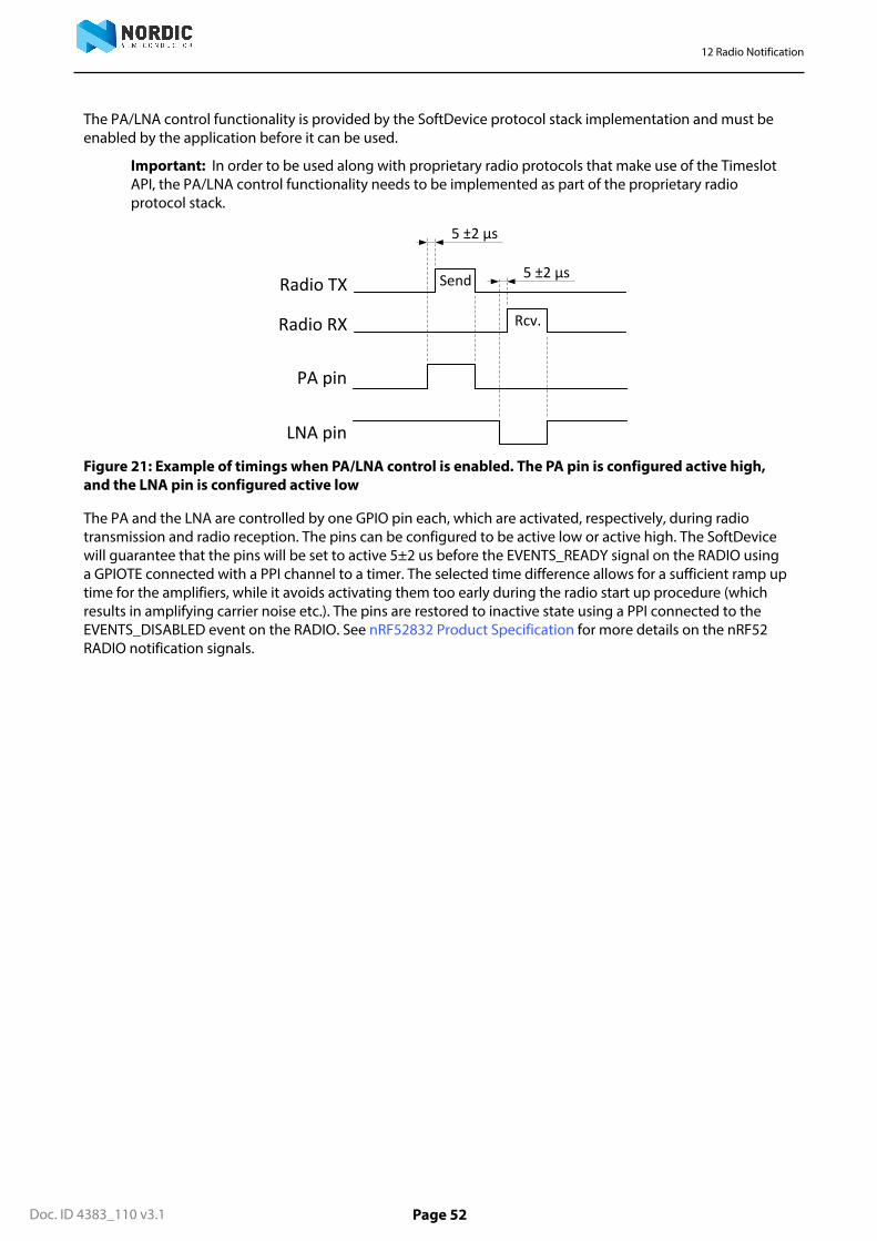
12 Radio Notification
Doc. ID 4383_110 v3.1 Page 52
The PA/LNA control functionality is provided by the SoftDevice protocol stack implementation and must beenabled by the application before it can be used.
Important: In order to be used along with proprietary radio protocols that make use of the TimeslotAPI, the PA/LNA control functionality needs to be implemented as part of the proprietary radioprotocol stack.
PA pin
LNA pin
Radio TX
Radio RX
Send
Rcv.
5 ±2 µs
5 ±2 µs
Figure 21: Example of timings when PA/LNA control is enabled. The PA pin is configured active high,and the LNA pin is configured active low
The PA and the LNA are controlled by one GPIO pin each, which are activated, respectively, during radiotransmission and radio reception. The pins can be configured to be active low or active high. The SoftDevicewill guarantee that the pins will be set to active 5±2 us before the EVENTS_READY signal on the RADIO usinga GPIOTE connected with a PPI channel to a timer. The selected time difference allows for a sufficient ramp uptime for the amplifiers, while it avoids activating them too early during the radio start up procedure (whichresults in amplifying carrier noise etc.). The pins are restored to inactive state using a PPI connected to theEVENTS_DISABLED event on the RADIO. See nRF52832 Product Specification for more details on the nRF52RADIO notification signals.

Doc. ID 4383_110 v3.1 Page 53
Chapter 13
Master Boot Record and bootloaderThe SoftDevice supports the use of a bootloader. A bootloader may be used to update the firmware on theSoC.
The nRF52 software architecture includes a Master Boot Record (MBR) ( Figure 1: System on Chip applicationwith the SoftDevice on page 11). The MBR is necessary in order for the bootloader to update the SoftDevice, orto update the bootloader itself. The MBR is a required component in the system. The inclusion of a bootloaderis optional.
13.1 Master Boot RecordThe main functionality of the MBR is to provide an interface to allow in-system updates of the SoftDevice andbootloader firmware.
The Master Boot Record (MBR) module occupies a defined region in the SoC program memory where theSystem Vector table resides.
All exceptions (reset, hard fault, interrupts, SVC) are, first, processed by the MBR and then are forwarded to theappropriate handlers (for example the bootloader or the SoftDevice exception handlers). See Interrupt modeland processor availability on page 72 for more details on the interrupt forwarding scheme.
During a firmware update process, the MBR is never erased. The MBR ensures that the bootloader can recoverfrom any unexpected resets during an ongoing update process.
In order to issue the SD_MBR_COMMAND_COPY_BL or SD_MBR_COMMAND_VECTOR_TABLE_BASE_SETcommands to the MBR, the UICR.NRFFW[1] register must be set to an address (MBRPARAMADDR addressin Figure 22: MBR, SoftDevice, and bootloader architecture on page 54 ) corresponding to a page in theApplication Flash Region (see Memory isolation and runtime protection on page 15). If UICR.NRFFW[1] is notset the commands will return NRF_ERROR_NO_MEM. This page will be cleared by the MBR and used to storeparameters before chip reset. When the UICR.NRFFW[1] register is set, the page it refers to must not be usedby the application. If the application does not want to reserve a page for the MBR parameters, it must leave theUICR.NRFFW[1] register to 0xFFFFFFFF (its default value).
13.2 BootloaderA bootloader may be used to handle in-system update procedures.
The bootloader has full access to the SoftDevice API and can be implemented like any application that usesthe SoftDevice. In particular, the bootloader can make use of the SoftDevice API for BLE communication.
The bootloader is supported in the SoftDevice architecture by using a configurable base address for thebootloader in the application Flash Region. The base address (BOOTLOADERADDR) is configured by settingthe UICR.NRFFW[0] register. The bootloader is responsible for determining the start address of the application.It uses sd_softdevice_vector_table_base_set(uint32_t address) to tell the SoftDevicewhere the application starts.
The bootloader is also responsible for keeping track of, and verifying the integrity of the SoftDevice. If anunexpected reset occurs during an update of the SoftDevice, it is the responsibility of the bootloader to detectthis and resume the update procedure.
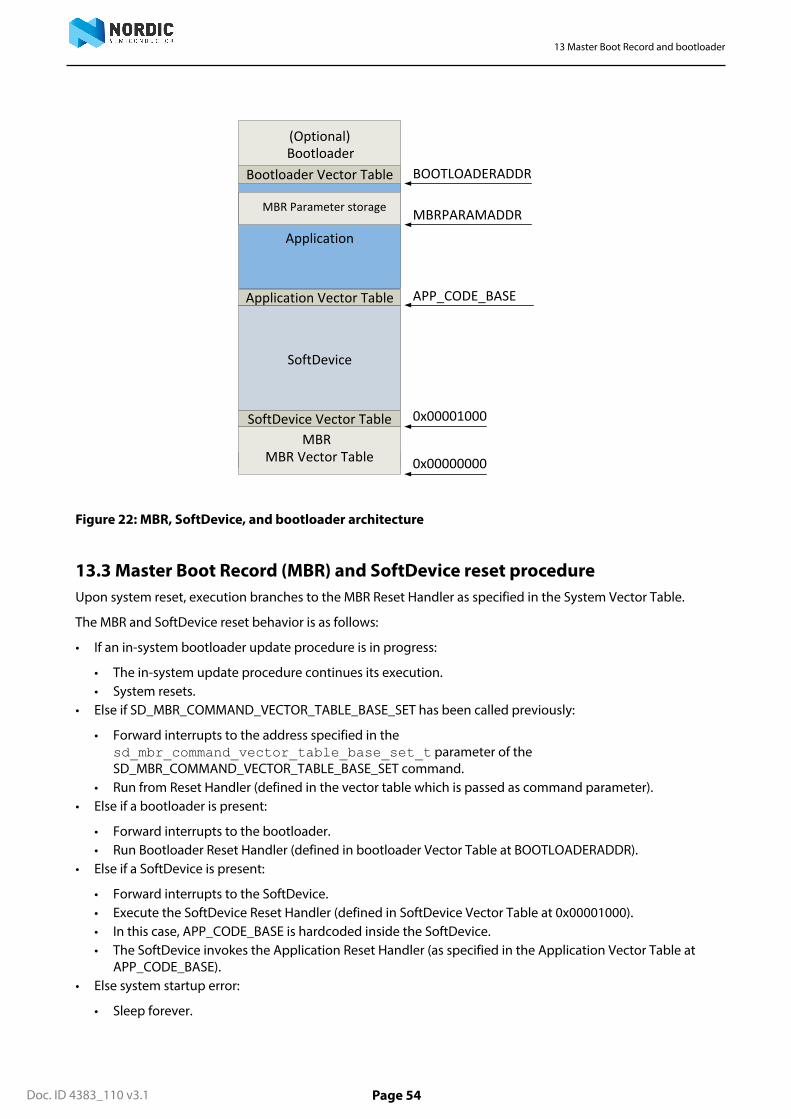
13 Master Boot Record and bootloader
Doc. ID 4383_110 v3.1 Page 54
SoftDevice
Application
Application Vector Table
SoftDevice Vector Table
APP_CODE_BASE
BOOTLOADERADDR Bootloader Vector Table
(Optional)Bootloader
0x00001000
MBR Vector TableMBR
0x00000000
SoftDevice Vector Table
MBR Parameter storage MBRPARAMADDR
Figure 22: MBR, SoftDevice, and bootloader architecture
13.3 Master Boot Record (MBR) and SoftDevice reset procedureUpon system reset, execution branches to the MBR Reset Handler as specified in the System Vector Table.
The MBR and SoftDevice reset behavior is as follows:
• If an in-system bootloader update procedure is in progress:
• The in-system update procedure continues its execution.• System resets.
• Else if SD_MBR_COMMAND_VECTOR_TABLE_BASE_SET has been called previously:
• Forward interrupts to the address specified in thesd_mbr_command_vector_table_base_set_t parameter of theSD_MBR_COMMAND_VECTOR_TABLE_BASE_SET command.
• Run from Reset Handler (defined in the vector table which is passed as command parameter).• Else if a bootloader is present:
• Forward interrupts to the bootloader.• Run Bootloader Reset Handler (defined in bootloader Vector Table at BOOTLOADERADDR).
• Else if a SoftDevice is present:
• Forward interrupts to the SoftDevice.• Execute the SoftDevice Reset Handler (defined in SoftDevice Vector Table at 0x00001000).• In this case, APP_CODE_BASE is hardcoded inside the SoftDevice.• The SoftDevice invokes the Application Reset Handler (as specified in the Application Vector Table at
APP_CODE_BASE).• Else system startup error:
• Sleep forever.
13 Master Boot Record and bootloader
Doc. ID 4383_110 v3.1 Page 55
13.4 Master Boot Record (MBR) and SoftDevice initialization procedureThe SoftDevice can be enabled by the bootloader.
The bootloader can enable the SoftDevice through the following step-by-step procedure:
1. Issuing a command for MBR to forward interrupts to the SoftDevice using sd_mbr_command() withSD_MBR_COMMAND_INIT_SD.
2. Issuing a command for the SoftDevice to forward interrupts to the bootloader usingsd_softdevice_vector_table_base_set(uint32_t address) with BOOTLOADERADDR asparameter.
3. Enabling the SoftDevice using sd_softdevice_enable().
The bootloader can transfer the execution from itself to the application through the following step-by-stepprocedure:
1. Issuing a command for MBR to forward interrupts to the SoftDevice using sd_mbr_command() withSD_MBR_COMMAND_INIT_SD, if interrupts are not forwarded to the SoftDevice.
2. Issuing sd_softdevice_disable(), to ensure that the SoftDevice is disabled.3. Issuing a command for the SoftDevice to forward interrupts to the application using
sd_softdevice_vector_table_base_set(uint32_t address) with APP_CODE_BASE as aparameter.
4. Branching to the application Reset Handler as specified in the Application Vector Table.

Doc. ID 4383_110 v3.1 Page 56
Chapter 14
SoftDevice information structureThe SoftDevice binary file contains an information structure.
The structure is illustrated in Figure 23: SoftDevice information structure on page 56. The location of thestructure, the SoftDevice size, and the firmware_id can be obtained at run time by the application usingmacros defined in the nrf_sdm.h header file. The information structure can also be accessed by parsing thebinary SoftDevice file.
012345678910111213141516171819202122232425262728293031word 0
word 1
word 2
word 3
Reserved for future use
magic_number
SoftDevice size
Reserved for future use
info_size
firmware_id
word 4
word 5
sd_id
sd_version
Figure 23: SoftDevice information structure

Doc. ID 4383_110 v3.1 Page 57
Chapter 15
SoftDevice memory usageThe SoftDevice shares the available flash memory and RAM on the nRF52 SoC with the application. Theapplication must therefore be aware of the memory resources needed by the SoftDevice and leave the parts ofthe memory used by the SoftDevice undisturbed for correct SoftDevice operation.
The SoftDevice requires a fixed amount of flash memory and RAM, which are detailed in Table 27: S132Memory resource requirements for flash on page 58 and Table 28: S132 Memory resource requirements forRAM on page 58. In addition, depending on the runtime configuration, the SoftDevice will require:
• Additional RAM for Bluetooth® low energy (BLE) roles and bandwidth (see Role configuration on page59)
• Attributes (see Attribute table size on page 59)• Security (see Security configuration on page 59)• UUID storage (see Vendor specific UUID counts on page 59)
15.1 Memory resource map and usageThe memory map for program memory and RAM when the SoftDevice is enabled is described in this section.
Figure 24: Memory resource map on page 57 illustrates the memory usage of the SoftDevice alongsidean user application. The flash memory for the SoftDevice is always reserved and the application programcode should be placed above the SoftDevice at APP_CODE_BASE. The SoftDevice uses the first 8 bytes ofRAM when not enabled. Once enabled, the RAM usage of the SoftDevice increases: the RAM requirementsof an enabled SoftDevice are detailed in Table 28: S132 Memory resource requirements for RAM on page58. With the exception of the call stack, the RAM usage for the SoftDevice is always isolated from theapplication usage; thus the application is required to not access the RAM region below APP_RAM_BASE. Thevalue of APP_RAM_BASE is obtained by calling sd_softdevice_enable, which will always return therequired minimum start address of the application RAM region for the given configuration. An access belowthe required minimum application RAM start address will result in undefined behavior, see Table 28: S132Memory resource requirements for RAM on page 58 for minimum RAM requirements.
SoftDevice
Application
Application Vector Table
SoftDevice Vector Table
RAMProgram Memory
SoftDevice
Application
0x20000000 + <size of RAM>Call Stack
Heap
Master Boot Record
MBR (System) Vector Table 0x00000000
0x00001000
APP_CODE_BASE
MBR 0x20000000
APP_RAM_BASE
0x00000000 + <size of flash>
Figure 24: Memory resource map

15 SoftDevice memory usage
Doc. ID 4383_110 v3.1 Page 58
15.1.1 Memory resource requirementsThe tables below show the memory resource requirements both when the S132 SoftDevice is enabled anddisabled.
Flash
Table 27: S132 Memory resource requirements for flash
Flash Value
Required by the SoftDevice 120 kB11
Required by the MBR 4 kB
APP_CODE_BASE address (absolute value) 0x0001F000
RAM
Table 28: S132 Memory resource requirements for RAM
RAM S132 Enabled S132 Disabled
Required by the SoftDevice (inbytes)
0x1348 + Configurable Resources
Minimum: 0x19c0 (6592)
8
APP_RAM_BASE address(minimum required value)
0x20000000 + SoftDevice RAMconsumption
Minimum: 0x200019c0
0x20000008
Call stack
By default, the nRF52 SoC will have a shared call stack with both application stack frames and SoftDevice stackframes, managed by the main stack pointer (MSP).
The call stack configuration is done by the application, and the MSP gets initialized on reset to the addressspecified by the application vector table entry 0. The application may, in its reset vector, configure the CPU touse the process stack pointer (PSP) in thread mode. This configuration is optional but may be required by anoperating system (OS); for example, to isolate application threads and OS context memory. The applicationprogrammer must be aware that the SoftDevice will use the MSP as it is always executed in exception mode.
Important: It is customary, but not required, to let the stack run downwards from the upper limit ofthe RAM Region.
With each release of an nRF52 SoftDevice, its maximum (worst case) call stack requirement may be updated.The SoftDevice uses the call stack when SoftDevice interrupt handlers execute. These are asynchronous to theapplication, so the application programmer must reserve call stack for the application in addition to the callstack requirement by the SoftDevice.
The application must reserve sufficient space to satisfy both the application and the nRF52 SoftDevicestack memory requirements. The nRF52 SoC has no designated hardware for detecting stack overflow. Theapplication can use the ARM®Cortex®-M4 MPU to implement a mechanism for stack overflow detection.
The SoftDevice does not use the ARM® Cortex®-M4 Floating-point Unit (FPU) and does not configure anyfloating-point registers. Table 29: S132 Memory resource requirements for call stack on page 59 depicts themaximum call stack size that may be consumed by the SoftDevice when not using the FPU.
11 1 kB = 1024 bytes
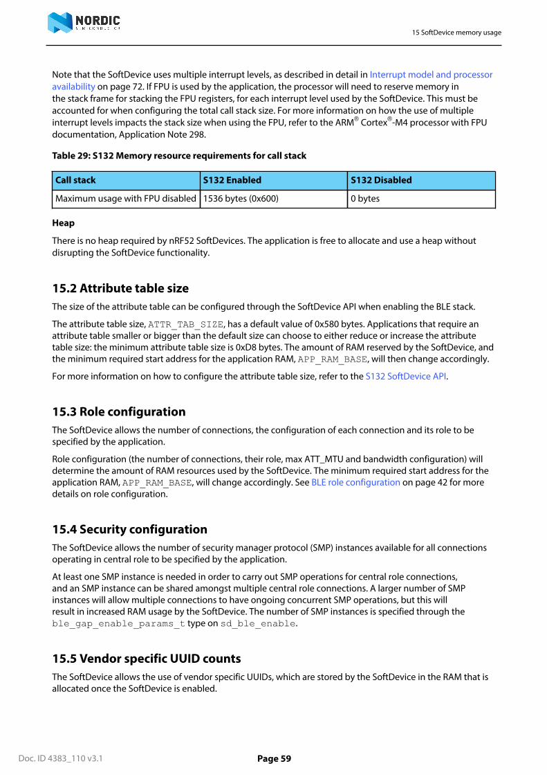
15 SoftDevice memory usage
Doc. ID 4383_110 v3.1 Page 59
Note that the SoftDevice uses multiple interrupt levels, as described in detail in Interrupt model and processoravailability on page 72. If FPU is used by the application, the processor will need to reserve memory inthe stack frame for stacking the FPU registers, for each interrupt level used by the SoftDevice. This must beaccounted for when configuring the total call stack size. For more information on how the use of multipleinterrupt levels impacts the stack size when using the FPU, refer to the ARM® Cortex®-M4 processor with FPUdocumentation, Application Note 298.
Table 29: S132 Memory resource requirements for call stack
Call stack S132 Enabled S132 Disabled
Maximum usage with FPU disabled 1536 bytes (0x600) 0 bytes
Heap
There is no heap required by nRF52 SoftDevices. The application is free to allocate and use a heap withoutdisrupting the SoftDevice functionality.
15.2 Attribute table sizeThe size of the attribute table can be configured through the SoftDevice API when enabling the BLE stack.
The attribute table size, ATTR_TAB_SIZE, has a default value of 0x580 bytes. Applications that require anattribute table smaller or bigger than the default size can choose to either reduce or increase the attributetable size: the minimum attribute table size is 0xD8 bytes. The amount of RAM reserved by the SoftDevice, andthe minimum required start address for the application RAM, APP_RAM_BASE, will then change accordingly.
For more information on how to configure the attribute table size, refer to the S132 SoftDevice API.
15.3 Role configurationThe SoftDevice allows the number of connections, the configuration of each connection and its role to bespecified by the application.
Role configuration (the number of connections, their role, max ATT_MTU and bandwidth configuration) willdetermine the amount of RAM resources used by the SoftDevice. The minimum required start address for theapplication RAM, APP_RAM_BASE, will change accordingly. See BLE role configuration on page 42 for moredetails on role configuration.
15.4 Security configurationThe SoftDevice allows the number of security manager protocol (SMP) instances available for all connectionsoperating in central role to be specified by the application.
At least one SMP instance is needed in order to carry out SMP operations for central role connections,and an SMP instance can be shared amongst multiple central role connections. A larger number of SMPinstances will allow multiple connections to have ongoing concurrent SMP operations, but this willresult in increased RAM usage by the SoftDevice. The number of SMP instances is specified through theble_gap_enable_params_t type on sd_ble_enable.
15.5 Vendor specific UUID countsThe SoftDevice allows the use of vendor specific UUIDs, which are stored by the SoftDevice in the RAM that isallocated once the SoftDevice is enabled.

15 SoftDevice memory usage
Doc. ID 4383_110 v3.1 Page 60
The number of vendor specific UUIDs that can be stored by the SoftDevice is set throughble_common_enable_params_t type on sd_ble_enable. The minimum number of vendor specificUUID count can be 1, whereas the default value is 10.
Doc. ID 4383_110 v3.1 Page 61
Chapter 16
SchedulingThe S132 stack has multiple activities, called timing-activities, which require exclusive access to certainhardware resources. These timing-activities are time multiplexed to give them the required exclusive accessfor a period of time, this is called a timing-event. Such timing-activities are BLE role events (central roles,peripheral roles), Flash memory API usage, and Radio Timeslot API timeslots.
If timing-events collide, their scheduling is determined by a priority system. If timing-activity A needs a timing-event at a time that overlaps with timing-activity B, and timing-activity A has higher priority, timing-activity Awill get the timing-event. Activity B will be blocked and its timing-event will be rescheduled for a later time. Ifboth timing-activity A and timing-activity B have same priority, the timing-activity which was requested firstwill get the timing-event.
The timing-activities run to completion and cannot be preempted by other timing-activities, even if thetiming-activity trying to preempt has a higher priority. This is the case, for example, when timing-activity A andtiming-activity B request timing-event at overlapping time with the same priority, and timing-activity A getsthe timing-event because it requested it earlier than timing-activity B. If timing-activity B increased its priorityand requested again, it would only get the timing-event if timing-activity A had not already started and therewas enough time to change the timing-event schedule.
16.1 SoftDevice timing-activities and prioritiesThe SoftDevice supports up to eight connections as a Central, up to one connection as a Peripheral, anAdvertiser or a Broadcaster and an Observer or Scanner simultaneously. In addition to these BLE roles, Flashmemory API and Radio Timeslot API can also run simultaneously.
An Initiator can only be started if there are less than eight connections established as a Central. Similarly, aconnectable Advertiser can only be started if there is no connection as a Peripheral established. See BLE roleconfiguration on page 42 for more information on the BLE stack configuration.
Central link timing-events are added relative to already running central link timing-events. Advertiser andbroadcaster timing-events are scheduled as early as possible. Peripheral link timing-events follow the timingsdictated by the connected peer. Peripheral role timing-events (peripheral link timing-event, advertiser/broadcaster timing-event) and central role timing-events (central link timing-event, initiator/scanner timing-event) are scheduled independently and so may occur at the same time and collide. Similarly, Flash accesstiming-event and Radio Timeslot timing-event are scheduled independently and so may occur at the sametime and collide.
The different timing-activities have different priorities at different times, dependent upon their state. Asan example, if a connection as a Peripheral is close to its supervision time-out it will block all other timing-activities and get the timing-event it requests. In this case all other timing-activities will be blocked if theyoverlap with the connection timing-event, and they will have to be rescheduled. Table Table 30: Schedulingpriorities on page 61 summarizes the priorities:
Table 30: Scheduling priorities
Priority (Decreasing order) Role state
First priority • Connection as a Peripheral during connectionupdate procedure.
• Connection setup as a Peripheral (waiting for ackfrom peer)

16 Scheduling
Doc. ID 4383_110 v3.1 Page 62
Priority (Decreasing order) Role state
• Connection as a Peripheral that is about to time-out
Second priority • Central connections that are about to time out
Third priority • Central connection setup (waiting for ack frompeer)
• Initiator• Advertiser/Broadcaster/Scanner which has been
blocked consecutively for a few times.
Important: An advertiser which is startedwhile a link as a Peripheral is active, doesnot increase its priority at all.
Fourth priority • All BLE roles in states other than above run withthis priority.
• Flash access after it has been blockedconsecutively for a few times.
• Radio Timeslot with high priority.
Last priority • Flash access• Radio Timeslot with normal priority
16.2 Initiator timingThis section introduces the different situations that happen with the Initiator when establishing a connection.
When establishing a connection with no other connections active, the Initiator will establish the connection inthe minimum time and allocate the first central link connection event 1.25 ms after the connect request wassent, as shown in Figure 25: Initiator - first connection on page 62.
Initiator
1.25 ms
C
connectionInterval
CADV
CREQ
Figure 25: Initiator - first connection
When establishing a new connection with other connections already made as a Central, the Initiator willstart asynchronously to the connected link timing-events and position the new central connection’s firsttiming-event in any free time between existing central timing-events or after the existing central timing-events. Central link timing-events will be placed close to each other (without any free time between them).This minimum time between start of two central role timing-event is referred as tEEO. tEEO is proportional tothe payload size and the number of packets exchanged (bandwidth configuration) in timing-event, becausemore time is required to exchange more and larger packets. Refer to Table 25: BLE Radio Notification timingranges on page 45 for tEEO timing ranges. Figure 26: Initiator - one central connection running on page 63illustrates the case of establishing a new central connection with one central connection already running.

16 Scheduling
Doc. ID 4383_110 v3.1 Page 63
tEEO-C0
InitiatorADV
CREQ
1.25 ms + transmittWindowOffset
C0
Connection Interval
C0
C1
tEEO-C0
C0
tEEO-Cn
Figure 26: Initiator - one central connection running
Important: The Initiator is scheduled asynchronously to any other role (and any other timing-activity)and assigned higher priority to ensure faster connection setup.
When a central link disconnects, the timings of other central link timing-events remain unchanged. Figure27: Initiator - free time due to disconnection on page 63 illustrates the case when central link C1 isdisconnected, which results in free time between C0 and C2.
C1
tEEO-C0
C3
C0
C2
tEEO-C1
tEEO-C2
tEEO-C3
Connection Interval
tEEO-C0
C3
C0
C2
tEEO-C2
tEEO-C3
Figure 27: Initiator - free time due to disconnection
When establishing a new connection in cases where free time is available between already running central linktiming-events, best fit algorithm is used to find which free time space should be used. Figure 28: Initiator - oneor more connections as a Central on page 63 illustrates the case when all existing central connections havethe same connection interval and the initiator timing-event starts around the same time as the 1st centralconnection (C0) timing-event in the schedule. There is available time between C1 - C2 and between C2 - C3.Timing-event for new connection, Cn, is positioned in the available time between C2 - C3 because that is thebest fit for Cn.
C1
tEEO-C0
InitiatorADV
CREQ
1.25 ms + transmittWindowOffset
C3
C0
C2
tEEO-C1
tEEO-C2 tEEO-C3
Connection Interval
C1
C3
C0
C2
C1
tEEO-C0
C3
C0
C2
tEEO-C2 tEEO-C3
Cn
tEEO-CntEEO-C1
Figure 28: Initiator - one or more connections as a Central
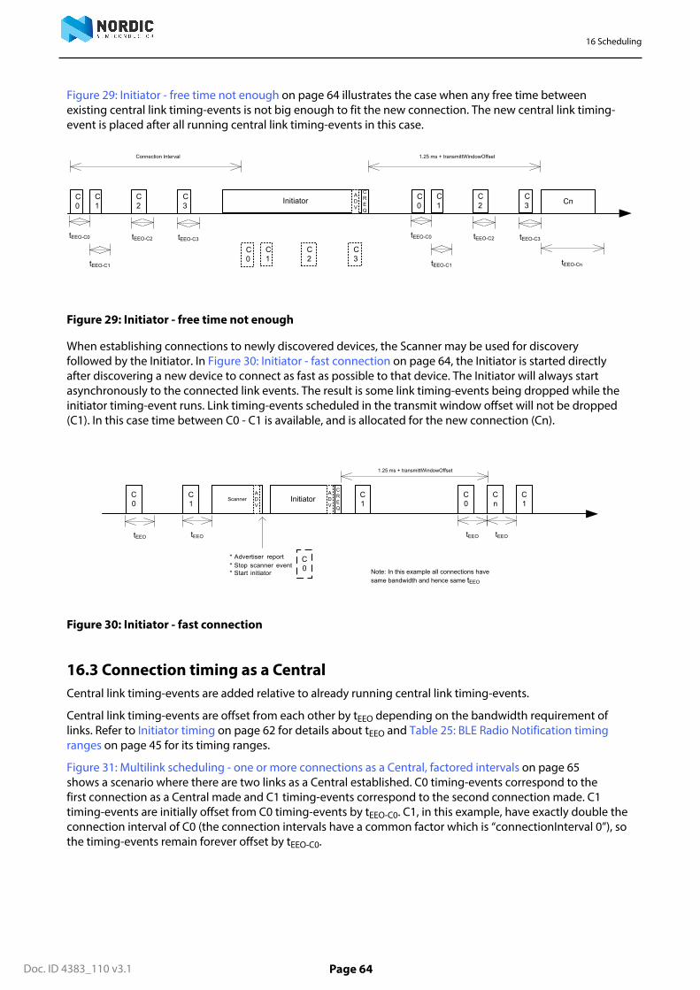
16 Scheduling
Doc. ID 4383_110 v3.1 Page 64
Figure 29: Initiator - free time not enough on page 64 illustrates the case when any free time betweenexisting central link timing-events is not big enough to fit the new connection. The new central link timing-event is placed after all running central link timing-events in this case.
C1
tEEO-C0
InitiatorADV
CREQ
1.25 ms + transmittWindowOffset
C3
C0
C2
tEEO-C1
tEEO-C2 tEEO-C3
Connection Interval
C1
C3
C0
C2
C1
tEEO-C0
C3
C0
C2
tEEO-C1
tEEO-C2 tEEO-C3
Cn
tEEO-Cn
Figure 29: Initiator - free time not enough
When establishing connections to newly discovered devices, the Scanner may be used for discoveryfollowed by the Initiator. In Figure 30: Initiator - fast connection on page 64, the Initiator is started directlyafter discovering a new device to connect as fast as possible to that device. The Initiator will always startasynchronously to the connected link events. The result is some link timing-events being dropped while theinitiator timing-event runs. Link timing-events scheduled in the transmit window offset will not be dropped(C1). In this case time between C0 - C1 is available, and is allocated for the new connection (Cn).
C0
C1Initiator C
0Cn
tEEO
C1
tEEO
ADV
CREQ
1.25 ms + transmittWindowOffset
C0
C1
ScannerADV
tEEO
* Advertiser report* Stop scanner event* Start initiator Note: In this example all connections have
same bandwidth and hence same tEEO
tEEO
Figure 30: Initiator - fast connection
16.3 Connection timing as a CentralCentral link timing-events are added relative to already running central link timing-events.
Central link timing-events are offset from each other by tEEO depending on the bandwidth requirement oflinks. Refer to Initiator timing on page 62 for details about tEEO and Table 25: BLE Radio Notification timingranges on page 45 for its timing ranges.
Figure 31: Multilink scheduling - one or more connections as a Central, factored intervals on page 65shows a scenario where there are two links as a Central established. C0 timing-events correspond to thefirst connection as a Central made and C1 timing-events correspond to the second connection made. C1timing-events are initially offset from C0 timing-events by tEEO-C0. C1, in this example, have exactly double theconnection interval of C0 (the connection intervals have a common factor which is “connectionInterval 0”), sothe timing-events remain forever offset by tEEO-C0.
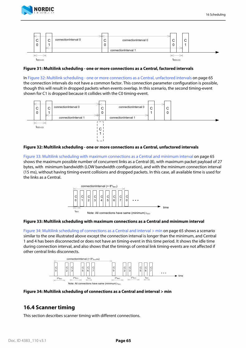
16 Scheduling
Doc. ID 4383_110 v3.1 Page 65
C0
tEEO-C0
C1
C0
connectionInterval 0 connectionInterval 0 C0
tEEO-C0
C1
connectionInterval 1
Figure 31: Multilink scheduling - one or more connections as a Central, factored intervals
In Figure 32: Multilink scheduling - one or more connections as a Central, unfactored intervals on page 65the connection intervals do not have a common factor. This connection parameter configuration is possible,though this will result in dropped packets when events overlap. In this scenario, the second timing-eventshown for C1 is dropped because it collides with the C0 timing-event.
C0
C1
C0
connectionInterval 0 C0
C1
C1
connectionInterval 1 connectionInterval 1
connectionInterval 0
tEEO-C0
Figure 32: Multilink scheduling - one or more connections as a Central, unfactored intervals
Figure 33: Multilink scheduling with maximum connections as a Central and minimum interval on page 65shows the maximum possible number of concurrent links as a Central (8), with maximum packet payload of 27bytes, with minimum bandwidth (LOW bandwidth configuration), and with the minimum connection interval(15 ms), without having timing-event collisions and dropped packets. In this case, all available time is used forthe links as a Central.
C0
time
…C0
connectionInterval (= 8*tEEO)
tEEO
C1
C2
C3
C4
C5
C6
C7
Note: All connections have same (minimum) tEEO
Figure 33: Multilink scheduling with maximum connections as a Central and minimum interval
Figure 34: Multilink scheduling of connections as a Central and interval > min on page 65 shows a scenariosimilar to the one illustrated above except the connection interval is longer than the minimum, and Central1 and 4 has been disconnected or does not have an timing-event in this time period. It shows the idle timeduring connection interval, and also shows that the timings of central link timing-events are not affected ifother central links disconnects.
C0
time…
connectionInterval (> 8*tEEOms)
C2
C3
C5
C6
C7
Note: All connections have same (minimum) tEEO
C0
C2
C3
C5
C6
C7
2*tEEO 2*tEEO tEEO 2*tEEO 2*tEEO tEEO
Figure 34: Multilink scheduling of connections as a Central and interval > min
16.4 Scanner timingThis section describes scanner timing with different connections.

16 Scheduling
Doc. ID 4383_110 v3.1 Page 66
Figure 35: Scanner timing - no active connections on page 66 shows that when scanning for advertiserswith no active connections, the scan interval and window can be any value within the Bluetooth® CoreSpecification.
Scanner
scanWindow = 1 ms to 10240 ms
time
scanInterval
Scanner
Figure 35: Scanner timing - no active connections
Scanner timing-event is always placed after the central link timing-events. Figure 36: Scanner timing - oneor more connection as a Central on page 66 shows that when there is one or more active connections,the scanner or observer role timing-event will be placed after the link timing-events. With scanInterval equalto the connectionInterval and a scanWindow ≤ (connectionInterval - (∑tEEO+ tScanReserved)), scanning willproceed without packet loss.
ScannerC0
time
…
scanWindow
C0
connectionInterval
∑(tEEO-Cx) tScanReserved
C1
C7
C2
C3 C4 C
5 C6
Figure 36: Scanner timing - one or more connection as a Central
Figure 37: Scanner timing - always after connections on page 66 shows a scenario where free time isavailable between link timing-events, but still the scanner timing-event is placed after all connections.
ScannerC0
time
…
scanWindow
C0
connectionInterval
tScanReserved
C1
C3
C2
Figure 37: Scanner timing - always after connections
Figure 38: Scanner timing - one connection, long window on page 66 shows a Scanner with a longscanWindow which will cause some connection timing-events to be dropped.
ScannerC0
time
scanWindow
C0
connectionInterval
tEEO-C0
Figure 38: Scanner timing - one connection, long window

16 Scheduling
Doc. ID 4383_110 v3.1 Page 67
16.5 Advertiser (connectable and non-connectable) timingAdvertiser is started as early as possible, after a random delay in the range of 3 - 13 ms, asynchronously to anyother role timing-events. If no roles are running, advertiser timing-evens are able to start and run without anycollision.
Adv
Adv
Adv interval + random delay Adv
Adv interval + random delayrandom delay
sd_ble_gap_adv_start()
Figure 39: Advertiser
When other role timing-events are running in addition, the advertiser role timing-event may collide withthose. Figure 40: Advertiser collide on page 67 shows a scenario of Advertiser colliding with Peripheral (P).
P PAdv
PAdv
P…
Adv
Figure 40: Advertiser collide
Directed advertiser is different compared to other advertiser types because it is not periodic. The schedulingof the single timing-event required by directed advertiser is done in the same way as other advertiser typetiming-events. Directed advertiser timing-event is also started as early as possible, and its priority (refer toTable 30: Scheduling priorities on page 61) is raised if it is blocked by other role timing-events multipletimes.
16.6 Peripheral connection setup and connection timingPeripheral link timing-events are added as per the timing dictated by peer Central.
ADV P
1.25 ms + WO
P
CI
CREQ
ADV
CI
P
Figure 41: Peripheral connection setup and connection
Peripheral link timing-events may collide with any other running role timing-events because the timing of theconnection as a Peripheral is dictated by the peer.
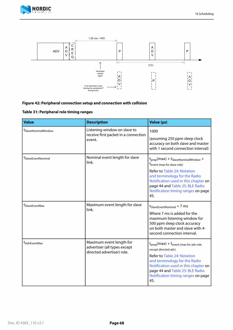
16 Scheduling
Doc. ID 4383_110 v3.1 Page 68
PADV
ADV P
1.25 ms + WO
ADV
CREQ
ADV
2*CI
P
ADV
Advertiser started again
First advertiser event blocked by peripheral P
timing-event.
Figure 42: Peripheral connection setup and connection with collision
Table 31: Peripheral role timing ranges
Value Description Value (μs)
tSlaveNominalWindow Listening window on slave toreceive first packet in a connectionevent.
1000
(assuming 250 ppm sleep clockaccuracy on both slave and masterwith 1 second connection interval)
tSlaveEventNominal Nominal event length for slavelink.
tprep(max) + tSlaveNominalWindow +tevent (max for slave role)
Refer to Table 24: Notationand terminology for the RadioNotification used in this chapter onpage 44 and Table 25: BLE RadioNotification timing ranges on page45.
tSlaveEventMax Maximum event length for slavelink.
tSlaveEventNominal + 7 ms
Where 7 ms is added for themaximum listening window for500 ppm sleep clock accuracyon both master and slave with 4-second connection interval.
tAdvEventMax Maximum event length foradvertiser (all types exceptdirected advertiser) role.
tprep(max) + tevent (max for adv role
except directed adv)
Refer to Table 24: Notationand terminology for the RadioNotification used in this chapter onpage 44 and Table 25: BLE RadioNotification timing ranges on page45.
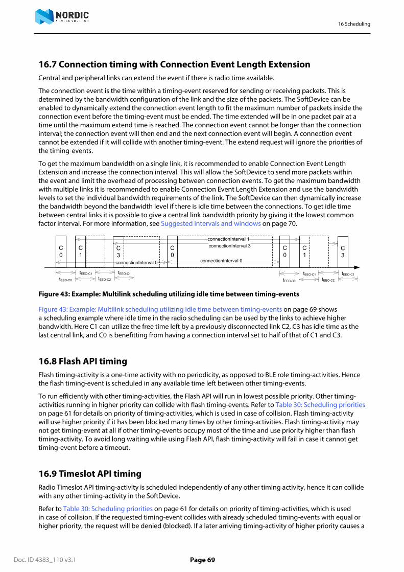
16 Scheduling
Doc. ID 4383_110 v3.1 Page 69
16.7 Connection timing with Connection Event Length ExtensionCentral and peripheral links can extend the event if there is radio time available.
The connection event is the time within a timing-event reserved for sending or receiving packets. This isdetermined by the bandwidth configuration of the link and the size of the packets. The SoftDevice can beenabled to dynamically extend the connection event length to fit the maximum number of packets inside theconnection event before the timing-event must be ended. The time extended will be in one packet pair at atime until the maximum extend time is reached. The connection event cannot be longer than the connectioninterval; the connection event will then end and the next connection event will begin. A connection eventcannot be extended if it will collide with another timing-event. The extend request will ignore the priorities ofthe timing-events.
To get the maximum bandwidth on a single link, it is recommended to enable Connection Event LengthExtension and increase the connection interval. This will allow the SoftDevice to send more packets withinthe event and limit the overhead of processing between connection events. To get the maximum bandwidthwith multiple links it is recommended to enable Connection Event Length Extension and use the bandwidthlevels to set the individual bandwidth requirements of the link. The SoftDevice can then dynamically increasethe bandwidth beyond the bandwidth level if there is idle time between the connections. To get idle timebetween central links it is possible to give a central link bandwidth priority by giving it the lowest commonfactor interval. For more information, see Suggested intervals and windows on page 70.
C3
C0
tEEO-C0
C1
C0
connectionInterval 0 connectionInterval 0
C0
C1
connectionInterval 1
C3
tEEO-C1
tEEO-C2
tEEO-C1
tEEO-C0
tEEO-C1
tEEO-C2
tEEO-C1
connectionInterval 3
Figure 43: Example: Multilink scheduling utilizing idle time between timing-events
Figure 43: Example: Multilink scheduling utilizing idle time between timing-events on page 69 showsa scheduling example where idle time in the radio scheduling can be used by the links to achieve higherbandwidth. Here C1 can utilize the free time left by a previously disconnected link C2, C3 has idle time as thelast central link, and C0 is benefitting from having a connection interval set to half of that of C1 and C3.
16.8 Flash API timingFlash timing-activity is a one-time activity with no periodicity, as opposed to BLE role timing-activities. Hencethe flash timing-event is scheduled in any available time left between other timing-events.
To run efficiently with other timing-activities, the Flash API will run in lowest possible priority. Other timing-activities running in higher priority can collide with flash timing-events. Refer to Table 30: Scheduling prioritieson page 61 for details on priority of timing-activities, which is used in case of collision. Flash timing-activitywill use higher priority if it has been blocked many times by other timing-activities. Flash timing-activity maynot get timing-event at all if other timing-events occupy most of the time and use priority higher than flashtiming-activity. To avoid long waiting while using Flash API, flash timing-activity will fail in case it cannot gettiming-event before a timeout.
16.9 Timeslot API timingRadio Timeslot API timing-activity is scheduled independently of any other timing activity, hence it can collidewith any other timing-activity in the SoftDevice.
Refer to Table 30: Scheduling priorities on page 61 for details on priority of timing-activities, which is usedin case of collision. If the requested timing-event collides with already scheduled timing-events with equal orhigher priority, the request will be denied (blocked). If a later arriving timing-activity of higher priority causes a

16 Scheduling
Doc. ID 4383_110 v3.1 Page 70
collision, the request will be canceled. However, a timing-event that has already started cannot be interruptedor canceled.
If the timeslot is requested as earliest possible, Timeslot timing-event is scheduled in any available free time.Hence there is less probability of collision with earliest possible request. Timeslot API timing-activity have twoconfigurable priorities. To run efficiently with other timing-activities, the Timeslot API should run in lowestpossible priority. It can be configured to use higher priority if it has been blocked many times by other timing-activities and is in a critical state.
16.10 Suggested intervals and windowsThe time required to fit one timing-event of all active central links is equal to the sum of tEEO of all activecentral links.
Therefore, eight link timing-events can complete in maximum ∑tEEO-Cx, which is around 15 ms for 27 bytemaximum packet payload and LOW bandwidth configuration. Refer to Table 24: Notation and terminology forthe Radio Notification used in this chapter on page 44 and Table 25: BLE Radio Notification timing ranges onpage 45 for timing ranges in central role.
Note that this does not leave sufficient time in the schedule for scanning or initiating new connections (whenthe number of connections already established is less than eight). Scanner, observer, and initiator events cantherefore cause connection packets to be dropped.
It is recommended that all connections have intervals that have a common factor. This common factor shouldbe greater or equal to ∑tEEO-Cx. Note that this sum depends on number of connections and their respectivebandwidth. In the case of eight connections with LOW bandwidth it is 15 ms, for three connections withMID bandwidth it is 11.25 ms (assuming maximum packet payload of 27 bytes). In case of using 15 ms as thecommon factor, all connections would have an interval of 15 ms or a multiple of 15 ms like 30 ms, 45 ms, etc.
If short connection intervals are not essential to the application and there is a need to have a Scanner runningat the same time as connections, then it is possible to avoid dropping packets on any connection as a Centralby having a connection interval larger than ∑tEEO-Cx plus the scanWindow plus tScanReserved. Note that theInitiator is scheduled asynchronously to any other role (and any other timing-activity), hence initiator timing-event might collide with other timing-events even if above recommendation is followed.
As an example, setting the connection interval to 43.75 ms will allow three connection events with MIDbandwidth and a scan window of 31.0 ms, which is sufficient to ensure advertising packets from a 20 ms(nominal) advertiser hitting and being responded to within the window.
To summarize, a recommended configuration for operation without dropped packets for cases of only centralroles running is:
• All central role intervals (i.e. connection interval, scanner/observer/initiator intervals) should have acommon factor. This common factor should be ≥ ∑tEEO-Cx + scanWindow + tScanReserved.
Peripheral roles use the same time space as all other roles (including any other peripheral and central roles),hence a collision free schedule cannot be guaranteed if a peripheral role is running along with any other role.The probability of collision can be reduced (though not eliminated) if the central role link parameters are set assuggested in this section, and the following rules are applied for all roles:
• Interval of all roles have a common factor which is ≥ ∑tEEO-Cx + (tScanReserved + ScanWindow) +tSlaveEventNominal + tAdvEventMax
Important: tSlaveEventNominal can be used in above equation in most cases, but should be replacedby tSlaveEventMax for cases where links as a Peripheral can have worst sleep clock accuracy and longerconnection interval.
• Broadcaster and advertiser roles also follow the constraint of interval which can be factored by the smallestconnection interval.
Important: Directed advertiser is not considered here because that is not a periodic event.
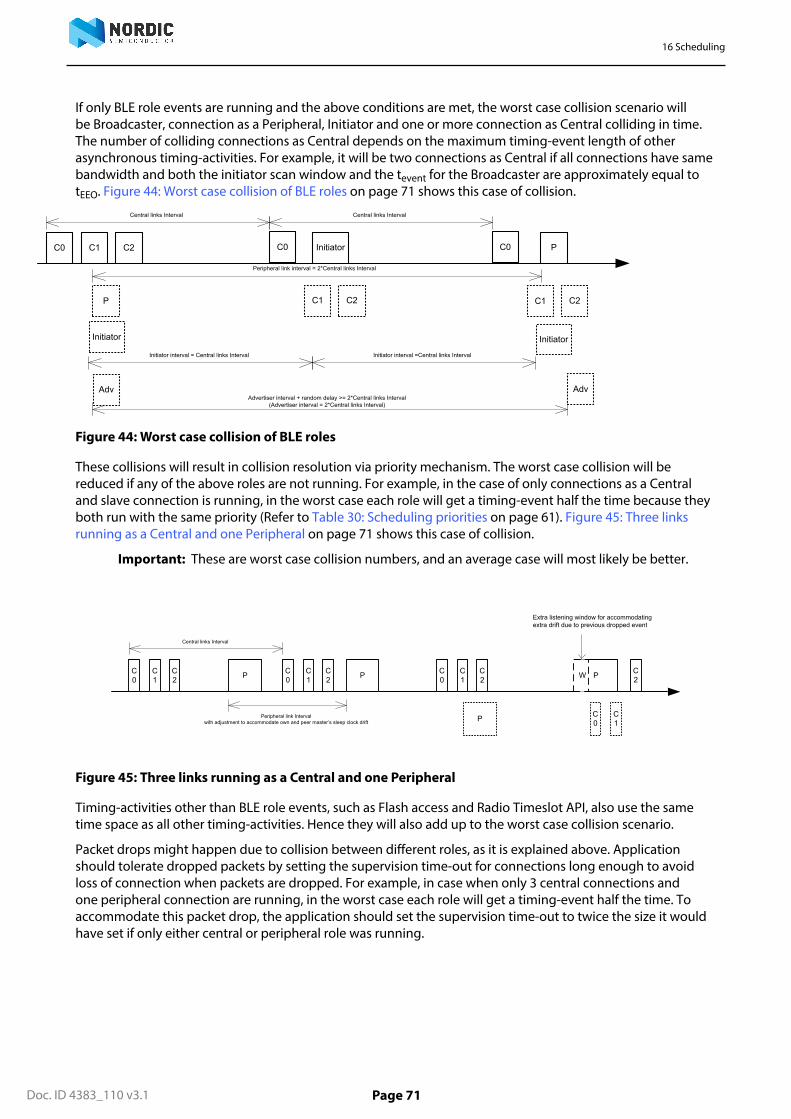
16 Scheduling
Doc. ID 4383_110 v3.1 Page 71
If only BLE role events are running and the above conditions are met, the worst case collision scenario willbe Broadcaster, connection as a Peripheral, Initiator and one or more connection as Central colliding in time.The number of colliding connections as Central depends on the maximum timing-event length of otherasynchronous timing-activities. For example, it will be two connections as Central if all connections have samebandwidth and both the initiator scan window and the tevent for the Broadcaster are approximately equal totEEO. Figure 44: Worst case collision of BLE roles on page 71 shows this case of collision.
C0
Central links Interval
C1 C2 C0
C1 C2P
Initiator
Adv
C0
C1 C2
Central links Interval
Initiator P
Initiator
Adv
Peripheral link interval = 2*Central links Interval
Advertiser interval + random delay >= 2*Central links Interval(Advertiser interval = 2*Central links Interval)
Initiator interval = Central links Interval Initiator interval =Central links Interval
Figure 44: Worst case collision of BLE roles
These collisions will result in collision resolution via priority mechanism. The worst case collision will bereduced if any of the above roles are not running. For example, in the case of only connections as a Centraland slave connection is running, in the worst case each role will get a timing-event half the time because theyboth run with the same priority (Refer to Table 30: Scheduling priorities on page 61). Figure 45: Three linksrunning as a Central and one Peripheral on page 71 shows this case of collision.
Important: These are worst case collision numbers, and an average case will most likely be better.
C0
C1
C2
C0
C1
C2
C0
C1
C2P
Central links Interval
C0
C1
C2P
P
P
Peripheral link Intervalwith adjustment to accommodate own and peer master’s sleep clock drift
W
Extra listening window for accommodating extra drift due to previous dropped event
Figure 45: Three links running as a Central and one Peripheral
Timing-activities other than BLE role events, such as Flash access and Radio Timeslot API, also use the sametime space as all other timing-activities. Hence they will also add up to the worst case collision scenario.
Packet drops might happen due to collision between different roles, as it is explained above. Applicationshould tolerate dropped packets by setting the supervision time-out for connections long enough to avoidloss of connection when packets are dropped. For example, in case when only 3 central connections andone peripheral connection are running, in the worst case each role will get a timing-event half the time. Toaccommodate this packet drop, the application should set the supervision time-out to twice the size it wouldhave set if only either central or peripheral role was running.

Doc. ID 4383_110 v3.1 Page 72
Chapter 17
Interrupt model and processoravailabilityThis chapter documents the SoftDevice interrupt model, how interrupts are forwarded to the application, anddescribes how long the processor is used by the SoftDevice in different priority levels.
17.1 Exception modelAs the SoftDevice, including the Master Boot Record (MBR), needs to handle some interrupts, all interrupts arerouted through the MBR and SoftDevice. The ones that should be handled by the application are forwardedand the rest are handled within the SoftDevice itself. This section describes the interrupt forwardingmechanism.
For more information on the MBR, see Master Boot Record and bootloader on page 53.
17.1.1 Interrupt forwarding to the applicationThe forwarding of interrupts to the application depends on the state of the SoftDevice.
At the lowest level, the MBR receives all interrupts and forwards them to the SoftDevice regardless of whetherthe SoftDevice is enabled or not. The use of a bootloader introduces some exceptions to this, see Master BootRecord and bootloader on page 53.
Some peripherals and their respective interrupt numbers are reserved for use by the SoftDevice (see Hardwareperipherals on page 20). Any interrupt handler defined by the application for these interrupts will not becalled as long as the SoftDevice is enabled. When the SoftDevice is disabled, these interrupts will be forwardedto the application.
The SVC interrupt is always intercepted by the SoftDevice regardless of whether it is enabled or disabled. TheSoftDevice inspects the SVC number, and if it is equal or greater than 0x10, the interrupt is processed by theSoftDevice. SVC numbers below 0x10 are forwarded to the application's SVC interrupt handler. This allows theapplication to make use of a range of SVC numbers for its own purpose, for example, for an RTOS.
Interrupts not used by the SoftDevice are always forwarded to the application.
For the SoftDevice to locate the application interrupt vectors, the application must define its interrupt vectortable at the bottom of the Application Flash Region illustrated in Figure 24: Memory resource map on page 57.When the base address of the application code is directly after the top address of the SoftDevice, the code canbe developed as a standard ARM® Cortex® -M4 application project with the compiler creating the interruptvector table.
17.1.2 Interrupt latency due to System on Chip (SoC) frameworkLatency, additional to ARM® Cortex® -M4 hardware architecture latency, is introduced by SoftDevice logic tomanage interrupt events.
This latency occurs when an interrupt is forwarded to the application from the SoftDevice and is part of theminimum latency for each application interrupt. This is the latency added by the interrupt forwarding latencyalone. The maximum application interrupt latency is dependent on SoftDevice activity, as described in sectionProcessor usage patterns and availability on page 75.
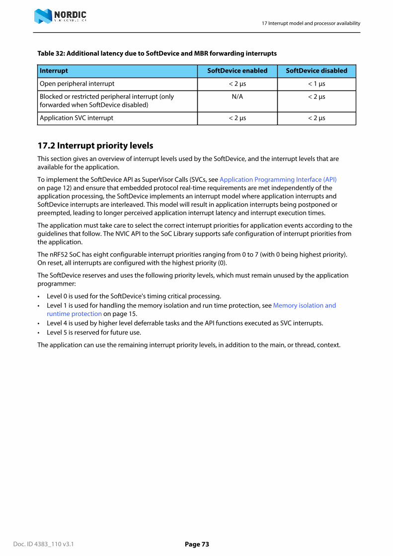
17 Interrupt model and processor availability
Doc. ID 4383_110 v3.1 Page 73
Table 32: Additional latency due to SoftDevice and MBR forwarding interrupts
Interrupt SoftDevice enabled SoftDevice disabled
Open peripheral interrupt < 2 μs < 1 μs
Blocked or restricted peripheral interrupt (onlyforwarded when SoftDevice disabled)
N/A < 2 μs
Application SVC interrupt < 2 μs < 2 μs
17.2 Interrupt priority levelsThis section gives an overview of interrupt levels used by the SoftDevice, and the interrupt levels that areavailable for the application.
To implement the SoftDevice API as SuperVisor Calls (SVCs, see Application Programming Interface (API)on page 12) and ensure that embedded protocol real-time requirements are met independently of theapplication processing, the SoftDevice implements an interrupt model where application interrupts andSoftDevice interrupts are interleaved. This model will result in application interrupts being postponed orpreempted, leading to longer perceived application interrupt latency and interrupt execution times.
The application must take care to select the correct interrupt priorities for application events according to theguidelines that follow. The NVIC API to the SoC Library supports safe configuration of interrupt priorities fromthe application.
The nRF52 SoC has eight configurable interrupt priorities ranging from 0 to 7 (with 0 being highest priority).On reset, all interrupts are configured with the highest priority (0).
The SoftDevice reserves and uses the following priority levels, which must remain unused by the applicationprogrammer:
• Level 0 is used for the SoftDevice's timing critical processing.• Level 1 is used for handling the memory isolation and run time protection, see Memory isolation and
runtime protection on page 15.• Level 4 is used by higher level deferrable tasks and the API functions executed as SVC interrupts.• Level 5 is reserved for future use.
The application can use the remaining interrupt priority levels, in addition to the main, or thread, context.

17 Interrupt model and processor availability
Doc. ID 4383_110 v3.1 Page 74
Lowest priority
Highest priority
Reset
Non-maskable interrupt
Hard Fault
Cortex M4 Priorities
-3
-2
-1
0
1
2
3
4
SoftDevice memory protection
Application interrupts
Application interrupts
SoftDevice API calls and non-time-critical processing
SoftDevice timing-critical
5
6
7
SoftDevice reserved for future use
Application interrupts
Application interrupts
MainThread
Figure 46: Exception model
As seen from Figure 46: Exception model on page 74, the application has available priority level 2 and 3,located between the higher and lower priority levels reserved by the SoftDevice. This enables a low-latencyapplication interrupt to support fast sensor interfaces. An application interrupt at priority level 2 or 3 will onlyexperience latency from SoftDevice interrupts at priority levels 0 and 1, while application interrupts at prioritylevels 6 or 7 can experience latency from all SoftDevice priority levels.
Important: The priorities of the interrupts reserved by the SoftDevice cannot be changed. Thisincludes the SVC interrupt. Handlers running at a priority level higher than 4 (lower numerical priorityvalue) have neither access to SoftDevice functions nor to application specific SVCs or RTOS functionsrunning at lower priority levels (higher numerical priority values).
Figure 47: SoftDevice exception examples (some priority levels left out for clarity) on page 75 shows anexample of how interrupts with different priorities may run and preempt each other. Note that some prioritylevels are left out for clarity.
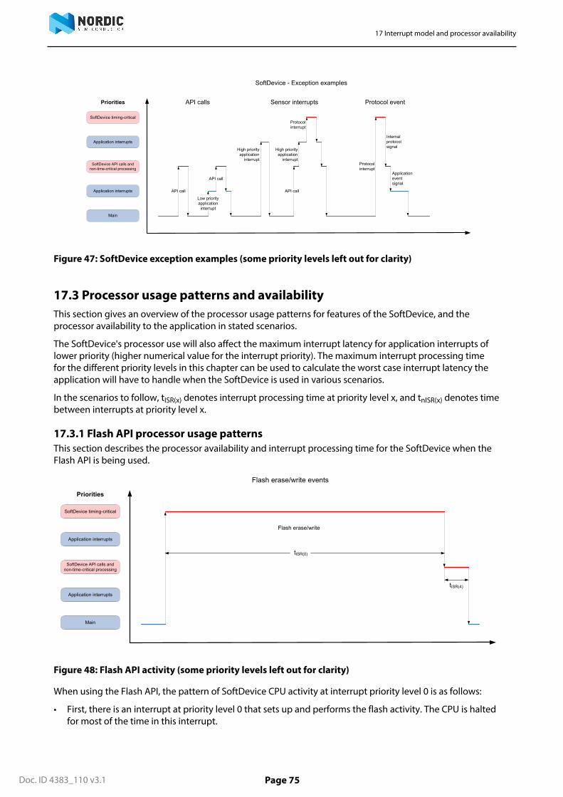
17 Interrupt model and processor availability
Doc. ID 4383_110 v3.1 Page 75
API call
SoftDevice - Exception examples
Priorities
Application interrupts
SoftDevice API calls and non-time-critical processing
Application interrupts
Main
SoftDevice timing-critical
Low priorityapplication
interrupt
API call
High priorityapplication
interrupt
API call
Protocolinterrupt
Protocolinterrupt
Internalprotocolsignal
Applicationeventsignal
High priorityapplication
interrupt
API calls Sensor interrupts Protocol event
Figure 47: SoftDevice exception examples (some priority levels left out for clarity)
17.3 Processor usage patterns and availabilityThis section gives an overview of the processor usage patterns for features of the SoftDevice, and theprocessor availability to the application in stated scenarios.
The SoftDevice's processor use will also affect the maximum interrupt latency for application interrupts oflower priority (higher numerical value for the interrupt priority). The maximum interrupt processing timefor the different priority levels in this chapter can be used to calculate the worst case interrupt latency theapplication will have to handle when the SoftDevice is used in various scenarios.
In the scenarios to follow, tISR(x) denotes interrupt processing time at priority level x, and tnISR(x) denotes timebetween interrupts at priority level x.
17.3.1 Flash API processor usage patternsThis section describes the processor availability and interrupt processing time for the SoftDevice when theFlash API is being used.
tISR(0)
Flash erase/write events
Flash erase/write
Priorities
Application interrupts
SoftDevice API calls and non-time-critical processing
Application interrupts
Main
SoftDevice timing-critical
tISR(4)
Figure 48: Flash API activity (some priority levels left out for clarity)
When using the Flash API, the pattern of SoftDevice CPU activity at interrupt priority level 0 is as follows:
• First, there is an interrupt at priority level 0 that sets up and performs the flash activity. The CPU is haltedfor most of the time in this interrupt.

17 Interrupt model and processor availability
Doc. ID 4383_110 v3.1 Page 76
• After the first interrupt is finished, there is another interrupt at priority level 4 that does some cleanup afterthe flash operation.
SoftDevice processing activity in the different priority levels during flash erase and write is outlined in thetable below.
Table 33: Processor usage for the Flash API
Parameter Description Min Typical Max
tISR(0),FlashErase Interrupt processing when erasinga flash page. Note that the CPU ishalted most of the length of thisinterrupt.
90 ms
tISR(0),FlashWrite Interrupt processing when writingone or more words to flash. Notethat the CPU is halted most of thelength of this interrupt. The Maxtime provided is for writing oneword. When writing more thanone word, please see the ProductSpecification to find out how longtime is needed for per word towrite, and add to the Max timeprovided in this table.
500 μs
tISR(4) Priority level 4 interrupt at the endof flash write or erase.
10 μs
17.3.2 Radio Timeslot API processor usage patternsThis section describes the processor availability and interrupt processing time for the SoftDevice when theRadio Timeslot API is being used.
See Radio Timeslot API on page 29 for more information on the Radio Timeslot API.
tISR(0)
Radio timeslot events
Rad
io ti
mes
lot p
repa
re
Priorities
Application interrupts
SoftDevice API calls and non-time-critical processing
Application interrupts
Thread
SoftDevice timing-critical
tISR(0)
Rad
io ti
mes
lot s
tart/
activ
ity
tISR(0)
Rad
io ti
mes
lot a
ctiv
ity
tISR(0)
Rad
io ti
mes
lot a
ctiv
ity/e
nd
tISR(4)
Figure 49: Radio Timeslot API activity (some priority levels left out for clarity)
When using the Radio Timeslot API, the pattern of SoftDevice CPU activity at interrupt priority level 0 is asfollows:
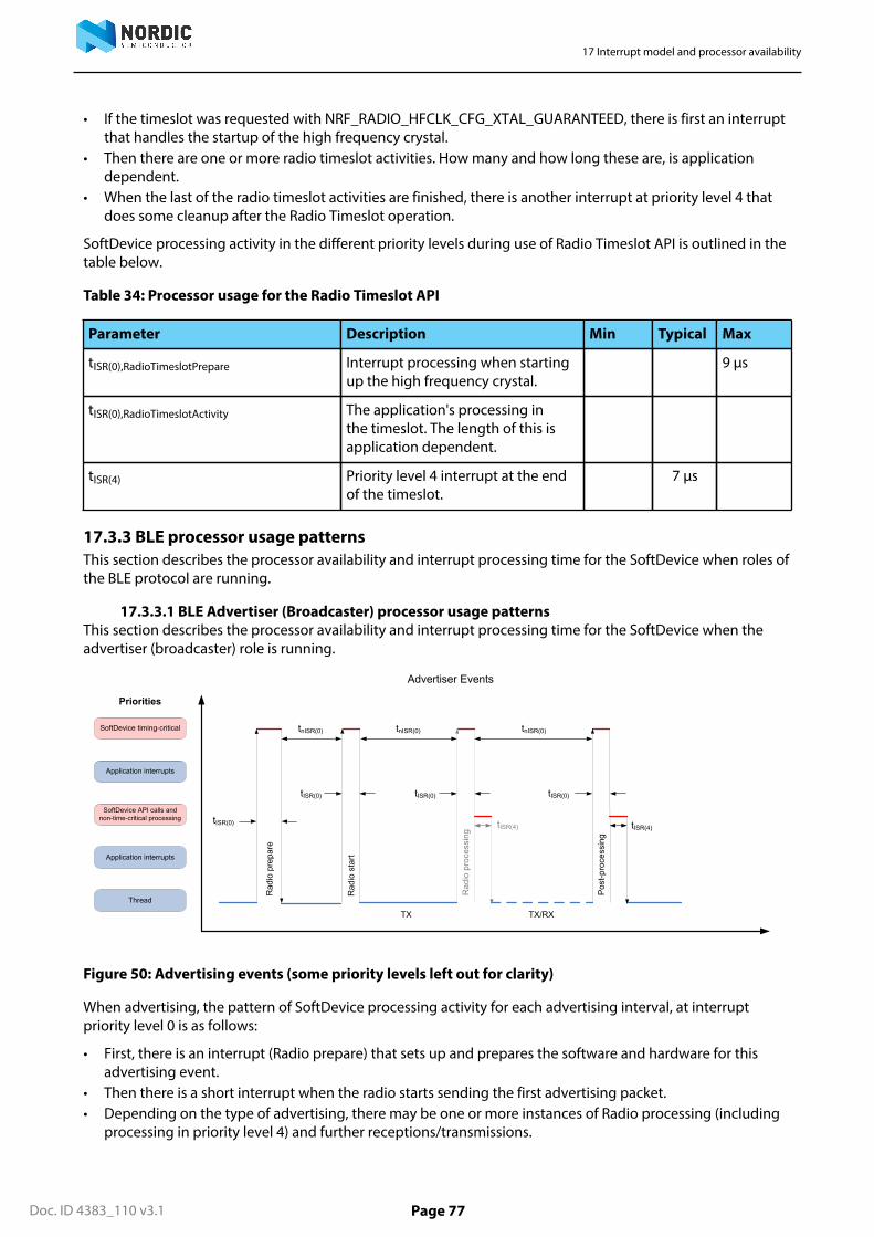
17 Interrupt model and processor availability
Doc. ID 4383_110 v3.1 Page 77
• If the timeslot was requested with NRF_RADIO_HFCLK_CFG_XTAL_GUARANTEED, there is first an interruptthat handles the startup of the high frequency crystal.
• Then there are one or more radio timeslot activities. How many and how long these are, is applicationdependent.
• When the last of the radio timeslot activities are finished, there is another interrupt at priority level 4 thatdoes some cleanup after the Radio Timeslot operation.
SoftDevice processing activity in the different priority levels during use of Radio Timeslot API is outlined in thetable below.
Table 34: Processor usage for the Radio Timeslot API
Parameter Description Min Typical Max
tISR(0),RadioTimeslotPrepare Interrupt processing when startingup the high frequency crystal.
9 μs
tISR(0),RadioTimeslotActivity The application's processing inthe timeslot. The length of this isapplication dependent.
tISR(4) Priority level 4 interrupt at the endof the timeslot.
7 μs
17.3.3 BLE processor usage patternsThis section describes the processor availability and interrupt processing time for the SoftDevice when roles ofthe BLE protocol are running.
17.3.3.1 BLE Advertiser (Broadcaster) processor usage patternsThis section describes the processor availability and interrupt processing time for the SoftDevice when theadvertiser (broadcaster) role is running.
tnISR(0)
tISR(0)
Rad
io s
tart
Advertiser Events
Rad
io p
repa
re
tISR(4)
tnISR(0)
Pos
t-pro
cess
ing
tISR(4)
Rad
io p
roce
ssin
g
tnISR(0)
TX TX/RX
tISR(0) tISR(0) tISR(0)
Priorities
Application interrupts
SoftDevice API calls and non-time-critical processing
Application interrupts
Thread
SoftDevice timing-critical
Figure 50: Advertising events (some priority levels left out for clarity)
When advertising, the pattern of SoftDevice processing activity for each advertising interval, at interruptpriority level 0 is as follows:
• First, there is an interrupt (Radio prepare) that sets up and prepares the software and hardware for thisadvertising event.
• Then there is a short interrupt when the radio starts sending the first advertising packet.• Depending on the type of advertising, there may be one or more instances of Radio processing (including
processing in priority level 4) and further receptions/transmissions.

17 Interrupt model and processor availability
Doc. ID 4383_110 v3.1 Page 78
• Finally, advertising ends with Post processing at interrupt priority level 0 and some interrupt priority level 4activity.
SoftDevice processing activity in the different priority levels when advertising is outlined in Table 35: Processorusage when advertising on page 78. The typical case is seen when advertising without using a whitelistand without receiving scan or connect requests. The max case can be seen when advertising with a fullwhitelist, receiving scan and connect requests while having a maximum number of connections and utilizingthe Radio Timeslot API and Flash memory API at the same time.
Table 35: Processor usage when advertising
Parameter Description Min Typical Max
tISR(0),RadioPrepare Processing preparing the radio foradvertising.
24 μs 50 μs
tISR(0),RadioStart Processing when starting theadvertising.
13 μs 20 μs
tISR(0),RadioProcessing Processing after sending/receivinga packet.
20 μs 40 μs
tISR(0),PostProcessing Processing at the end of anadvertising event.
75 μs 190 μs
tnISR(0) Distance between interrupts duringadvertising.
40 μs >170 μs
tISR(4) Priority level 4 interrupt at the endof an advertising event.
75 μs
From the table, we can calculate a typical processing time for one advertisement event sending threeadvertisement packets to be
tISR(0),RadioPrepare + tISR(0),RadioStart + 2 * tISR(0),RadioProcessing + tISR(0),PostProcessing + tISR(4) = 227 μs
which means that typically more than 99% of the processor time is available to the application whenadvertising with a 100 ms interval.
17.3.3.2 BLE peripheral connection processor usage patternsThis section describes the processor availability and interrupt processing time for the SoftDevice in aperipheral connection event.

17 Interrupt model and processor availability
Doc. ID 4383_110 v3.1 Page 79
tnISR(0)
tISR(0)
tISR(0)
tISR(4)
Connection Events
Rad
io p
repa
re
tnISR(0)
tISR(0)
Rad
io s
tart
tnISR(0)
tISR(0)
Rad
io p
roce
ssin
g
Pos
t-pro
cess
ing
RX TX
Priorities
Application interrupts
SoftDevice API calls and non-time-critical processing
Application interrupts
Thread
SoftDevice timing-critical
tISR(4)
Figure 51: Peripheral connection events (some priority levels left out for clarity)
In a peripheral connection event, the pattern of SoftDevice processing activity at interrupt priority level 0 istypically as follows:
• First, there is an interrupt (Radio prepare) that sets up and prepares the software and hardware for theconnection event.
• Then there is a short interrupt when the radio starts listening for the first packet.• When the reception is finished, there is Radio processing that processes the received packet and switches
the radio to transmission.• When the transmission is finished, there is either a Radio processing including a switch back to reception
and possibly a new transmission after that, or the event ends with post processing.• After the radio and post processings in priority level 0, the SoftDevice processes any received data packets,
executes any GATT, ATT or SMP operations and generates events to the application as required in prioritylevel 4. The interrupt at this priority level is therefore highly variable based on the stack operationsexecuted.
SoftDevice processing activity in the different priority levels during peripheral connection events is outlined inTable 36: Processor usage when connected on page 79. The typical case is seen when sending GATT writecommands writing 20 bytes. The max case can be seen when sending and receiving maximum length packetsand at the same time initiating encryption, while having a maximum number of connections and utilizing theRadio Timeslot API and Flash memory API at the same time.
Table 36: Processor usage when connected
Parameter Description Min Typical Max
tISR(0),RadioPrepare Processing preparing the radio for aconnection event.
35 μs 50 μs
tISR(0),RadioStart Processing when starting theconnection event.
15 μs 20 μs
tISR(0),RadioProcessing Processing after sending or receivinga packet.
30 μs 40 μs
tISR(0),PostProcessing Processing at the end of a connectionevent.
90 μs 231 μs

17 Interrupt model and processor availability
Doc. ID 4383_110 v3.1 Page 80
Parameter Description Min Typical Max
tnISR(0) Distance between interrupts during aconnection event.
30 μs > 190 μs
tISR(4) Priority level 4 interrupt after a packetis sent or received.
40 μs
From the table, we can calculate a typical processing time for a peripheral connection event where one packetis sent and received to be
tISR(0),RadioPrepare + tISR(0),RadioStart + tISR(0),RadioProcessing + tISR(0),PostProcessing + 2 * tISR(4) = 250 μs
which means that typically more than 99% of the processor time is available to the application when oneperipheral link is established and one packet is sent in each direction with a 100 ms connection interval.
17.3.3.3 BLE scanner and initiator processor usage patternsThis section describes the processor availability and interrupt processing time for the SoftDevice when thescanner or initiator role is running.
tnISR(0)
tISR(0)
Rad
io s
tart
Scanner Events
Rad
io p
repa
re
tISR(4)
tnISR(0)
Pos
t-pro
cess
ing
tISR(4)
Rad
io p
roce
ssin
g
tnISR(0)
RX TX/RX
tISR(0) tISR(0) tISR(0)
Priorities
Application interrupts
SoftDevice API calls and non-time-critical processing
Application interrupts
Thread
SoftDevice timing-critical
Figure 52: Scanning or initiating (some priority levels left out for clarity)
When scanning or initiating, the pattern of SoftDevice processing activity at interrupt priority level 0 is asfollows:
• First, there is an interrupt (Radio prepare) that sets up and prepares the software and hardware for thisscanner or initiator event.
• Then there is a short interrupt when the radio starts listening for advertisement packets.• During scanning, there will be zero or more instances of Radio processing, depending upon whether the
active role is a Scanner or an Initiator, whether scanning is passive or active, whether advertising packetsare received or not and upon the type of the received advertising packets. Such Radio processing may befollowed by the SoftDevice processing at interrupt priority level 4.
• When the event ends (either by timeout, or if the Initiator receives a connectable advertisement packetit accepts), the SoftDevice does some Post processing, which may be followed by processing at interruptpriority level 4.
SoftDevice processing activity in the different priority levels when scanning or initiating is outlined in Table 37:Processor usage for scanning or initiating on page 81. The typical case is seen when scanning or initiatingwithout using a whitelist and without sending scan or connect requests. The max case can be seen whenscanning or initiating with a full whitelist, sending scan or connect requests while having a maximum numberof connections and utilizing the Radio Timeslot API and Flash memory API at the same time.

17 Interrupt model and processor availability
Doc. ID 4383_110 v3.1 Page 81
Table 37: Processor usage for scanning or initiating
Parameter Description Min Typical Max
tISR(0),RadioPrepare Processing preparing the radio forscanning or initiating
18 μs 48 μs
tISR(0),RadioStart Processing when starting the scan orinitiation
19 μs 25 μs
tISR(0),RadioProcessing Processing after sending/receivingpacket
38 μs 60 μs
tISR(0),PostProcessing Processing at the end of a scanner orinitiator event
68 μs 190 μs
tnISR(0) Distance between interrupts duringscanning
30 μs >1.5 ms
tISR(4) Priority level 4 interrupt at the endof a scanner or initiator event
70 μs
From the table, we can calculate a typical processing time for one scan event receiving one advertisementpacket to be
tISR(0),RadioPrepare + tISR(0),RadioStart + tISR(0),RadioProcessing + tISR(0),PostProcessing + tISR(4) = 213 μs
which means that typically more than 99% of the processor time is available to the application when scanningwith a 100 ms interval under these conditions.
17.3.3.4 BLE central connection processor usage patternsThis section describes the processor availability and interrupt processing time for the SoftDevice in a centralconnection event.
tnISR(0)
tISR(0)
tISR(0)
tISR(4)
Connection Events
Rad
io p
repa
re
tnISR(0)
tISR(0)
Rad
io s
tart
tnISR(0)
tISR(0)
Rad
io p
roce
ssin
g
Pos
t-pro
cess
ing
RXTX
Priorities
Application interrupts
SoftDevice API calls and non-time-critical processing
Application interrupts
Thread
SoftDevice timing-critical
tISR(4)
Figure 53: Central connection events (some priority levels left out for clarity)
In a central connection event, the pattern of SoftDevice processing activity at interrupt priority level 0 istypically as follows:
• First, there is an interrupt (Radio prepare) that sets up and prepares the software and hardware.• Then there is a short interrupt when the radio starts transmitting the first packet in the connection event.

17 Interrupt model and processor availability
Doc. ID 4383_110 v3.1 Page 82
• When the transmission is finished, there is Radio processing that switches the radio to reception.• When the reception is finished, there is a Radio processing that processes the received packet, and either
including a switch back to transmission and possibly a new reception after that, or the event ends withpost processing.
• After the radio and post processings in priority level 0, the SoftDevice processes any received data packets,executes any GATT, ATT or SMP operations and generates events to the application as required in prioritylevel 4. The interrupt at this priority level is therefore highly variable based on the stack operationsexecuted.
SoftDevice processing activity in the different priority levels during central connection events is outlined inTable 38: Processor usage latency when connected on page 82. The typical case is seen when receivingGATT write commands writing 20 bytes. The max case can be seen when sending and receiving maximumlength packets and at the same time initiating encryption, while having a maximum number of connectionsand utilizing the Radio Timeslot API and Flash memory API at the same time.
Table 38: Processor usage latency when connected
Parameter Description Min Typical Max
tISR(0),RadioPrepare Processing preparing the radio fora connection event.
29 μs 47 μs
tISR(0),RadioStart Processing when starting theconnection event.
19 μs 25 μs
tISR(0),RadioProcessing Processing after sending orreceiving a packet.
30 μs 60 μs
tISR(0),PostProcessing Processing at the end of aconnection event.
90 μs 230 μs
tnISR(0) Distance between connectionevent interrupts.
30 μs > 195 μs
tISR(4) Priority level 4 interrupt after apacket is sent or received.
40 μs
From the table, we can calculate a typical processing time for a central connection event where one packet issent and received to be
tISR(0),RadioPrepare + tISR(0),RadioStart + tISR(0),RadioProcessing + tISR(0),PostProcessing + 2 * tISR(4) = 248 μs
which means that typically more than 99% of the processor time is available to the application when oneperipheral link is established and one packet is sent in each direction with a 100 ms connection interval.
17.3.4 Interrupt latency when using multiple modules and rolesConcurrent use of the Flash API, Radio Timeslot API and/or one or more BLE roles can affect interrupt latency.
The same interrupt priority levels are used by all Flash API, Radio Timeslot API and BLE roles. When usingmore than one of these concurrently, their respective events can be scheduled back-to-back (see Schedulingon page 28 for more on scheduling). In those cases, the last interrupt in the activity by one module/role canbe directly followed by the first interrupt of the next activity. Therefore, to find the real worst-case interruptlatency in these cases the application developer must add the latency of the first and last interrupt for allcombination of roles that are used.
Example: If the application uses the Radio Timeslot API while having a BLE advertiser running, the worst caseinterrupt latency or interruption for an application interrupt is the largest of
• The worst case interrupt latency of the Radio Timeslot API• The worst case interrupt latency of the BLE advertiser role

17 Interrupt model and processor availability
Doc. ID 4383_110 v3.1 Page 83
• The sum of the max time of the first interrupt of the Radio Timeslot API and the last interrupt of the BLEadvertiser role
• The sum of the max time of the first interrupt of the BLE advertiser role and the last interrupt of the RadioTimeslot API
for the SoftDevice interrupts with higher priority level (lower numerical value) as the application interrupt.

Doc. ID 4383_110 v3.1 Page 84
Chapter 18
BLE data throughputThis chapter gives an indication of achievable BLE connection throughput for GATT procedures used to sendand receive data in stated SoftDevice configurations.
The throughput numbers listed in this chapter are based on measurements in an interference-free radioenvironment. Maximum throughput is only achievable if the application, without delay, reads data packetsas they are received and provides new data as packets are transmitted. The SoftDevice may transfer morepackets in a connection event than what is reserved by the bandwidth configuration in situations where thereis buffer space available in the SoftDevice and there is time available in the event. For example, in simplexcommunication, where data is transmitted in one direction only, more time will be available for sendingpackets. Therefore, there may be extra TX-RX packet pairs in connection events. Additionally, more time canbe made available for a connection by extending the connection events beyond their reserved time. SeeConnection timing with Connection Event Length Extension on page 69 for more information.
All data throughput values apply to packet transfers over an encrypted connection using maximum payloadsizes. Maximum LL payload size is 27 bytes, unless noted otherwise.
Table 39: Maximum data throughput with a single peripheral or central connection and a connectioninterval of 7.5 ms
Protocol ATT MTUsize
BW Config Method Maximum datathroughput
GATT Client 23 HIGH Receive Notification
Send Write command
Send Write request
Simultaneous receiveNotification and sendWrite command
149.3 kbps
149.3 kbps
10.6 kbps
127.9 kbps (eachdirection)
GATT Server 23 HIGH Send Notification
Receive Write command
Receive Write request
Simultaneous sendNotification and receiveWrite command
149.3 kbps
149.3 kbps
10.6 kbps
127.9 kbps (eachdirection)
GATT Server 158 HIGH Send Notification
Receive Write command
Receive Write request
Simultaneous sendNotification and receiveWrite command
247.8 kbps
247.0 kbps
82.6 kbps
165.4 kbps (eachdirection)
GATT Client 23 MID Receive Notification
Send Write command
63.9 kbps
63.9 kbps
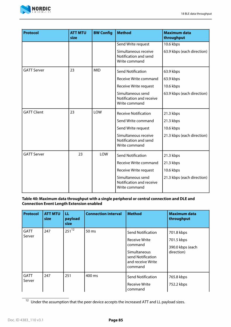
18 BLE data throughput
Doc. ID 4383_110 v3.1 Page 85
Protocol ATT MTUsize
BW Config Method Maximum datathroughput
Send Write request
Simultaneous receiveNotification and sendWrite command
10.6 kbps
63.9 kbps (each direction)
GATT Server 23 MID Send Notification
Receive Write command
Receive Write request
Simultaneous sendNotification and receiveWrite command
63.9 kbps
63.9 kbps
10.6 kbps
63.9 kbps (each direction)
GATT Client 23 LOW Receive Notification
Send Write command
Send Write request
Simultaneous receiveNotification and sendWrite command
21.3 kbps
21.3 kbps
10.6 kbps
21.3 kbps (each direction)
GATT Server 23 LOW Send Notification
Receive Write command
Receive Write request
Simultaneous sendNotification and receiveWrite command
21.3 kbps
21.3 kbps
10.6 kbps
21.3 kbps (each direction)
Table 40: Maximum data throughput with a single peripheral or central connection and DLE andConnection Event Length Extension enabled
Protocol ATT MTUsize
LLpayloadsize
Connection interval Method Maximum datathroughput
GATTServer
247 25112 50 ms Send Notification
Receive Writecommand
Simultaneoussend Notificationand receive Writecommand
701.8 kbps
701.5 kbps
390.0 kbps (eachdirection)
GATTServer
247 251 400 ms Send Notification
Receive Writecommand
765.8 kbps
752.2 kbps
12 Under the assumption that the peer device accepts the increased ATT and LL payload sizes.

18 BLE data throughput
Doc. ID 4383_110 v3.1 Page 86
Protocol ATT MTUsize
LLpayloadsize
Connection interval Method Maximum datathroughput
Simultaneoussend Notificationand receive Writecommand
421.7 kbps (eachdirection)
Raw LinkLayer data
N/A 251 400 ms N/A 803 kbps
The following table Table 41: Maximum data throughput for each connection, up to 8 connections with 23byte ATT MTU and no DLE on page 86 shows maximum data throughput at a connection interval of 15 msthat allows up to 8 LOW bandwidth concurrent connections per interval.
Only throughput for LOW bandwidth configuration is indicated. For higher bandwidth configurations, alonger connection interval would need to be used for each connection to prevent connection events fromoverlapping. See Scheduling on page 61 for more information on how connections can be configured.
Throughput may get reduced if a peripheral link is running because peripheral links are not synchronized withcentral links. If a peripheral link is running, throughput may decrease to half for up to two central links and theperipheral link.
Table 41: Maximum data throughput for each connection, up to 8 connections with 23 byte ATT MTUand no DLE
Protocol BW Config Method Maximum datathroughput
Receive Notification 9.1 kbps
Send Write command 9.0 kbps
Send Write request 4.5 kbpsGATT - Client LOW
Simultaneous receiveNotification and sendWrite command
9.1 kbps (each direction)
Send Notification 9.1 kbps
Receive Write command 9.0 kbps
Receive Write request 4.5 kbps
GATT - Server LOW
Simultaneous sendNotification and receiveWrite command
9.1 kbps (each direction)
Important: 1 kbps = 1000 bits per second
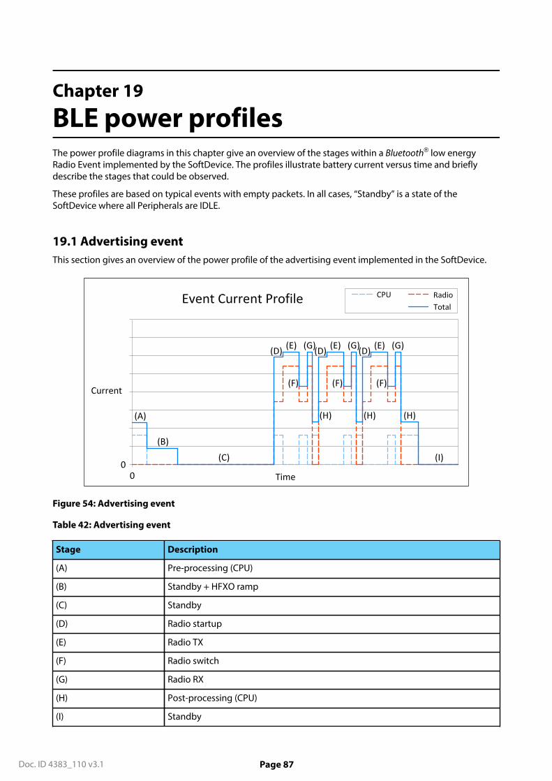
Doc. ID 4383_110 v3.1 Page 87
Chapter 19
BLE power profilesThe power profile diagrams in this chapter give an overview of the stages within a Bluetooth® low energyRadio Event implemented by the SoftDevice. The profiles illustrate battery current versus time and brieflydescribe the stages that could be observed.
These profiles are based on typical events with empty packets. In all cases, “Standby” is a state of theSoftDevice where all Peripherals are IDLE.
19.1 Advertising eventThis section gives an overview of the power profile of the advertising event implemented in the SoftDevice.
Figure 54: Advertising event
Table 42: Advertising event
Stage Description
(A) Pre-processing (CPU)
(B) Standby + HFXO ramp
(C) Standby
(D) Radio startup
(E) Radio TX
(F) Radio switch
(G) Radio RX
(H) Post-processing (CPU)
(I) Standby

19 BLE power profiles
Doc. ID 4383_110 v3.1 Page 88
19.2 Peripheral connection eventThis section gives an overview of the power profile of the peripheral connection event implemented in theSoftDevice.
Figure 55: Peripheral connection event
Table 43: Peripheral connection event
Stage Description
(A) Pre-processing (CPU)
(B) Standby + HFXO ramp
(C) Standby
(D) Radio startup
(E) Radio RX
(F) Radio switch
(G) Radio TX
(H) Post-processing (CPU)
(I) Standby
19.3 Scanning eventThis section gives an overview of the power profile of the scanning event implemented in the SoftDevice.

19 BLE power profiles
Doc. ID 4383_110 v3.1 Page 89
Figure 56: Scanning event
Table 44: Scanning event
Stage Description
(A) Pre-processing (CPU)
(B) Standby IDLE + HFXO ramp
(C) Standby
(D) Radio startup
(E) Radio RX
(F) Post-processing (CPU)
(G) Standby
19.4 Central connection eventThis section gives an overview of the power profile of the central connection event implemented in theSoftDevice.

19 BLE power profiles
Doc. ID 4383_110 v3.1 Page 90
Figure 57: Central connection event
Table 45: Central connection event
Stage Description
(A) Pre-processing (CPU)
(B) Standby + HFXO ramp
(C) Standby
(D) Radio startup
(E) Radio TX
(F) Radio switch
(G) Radio RX
(H) Post-processing (CPU)
(I) Standby

Doc. ID 4383_110 v3.1 Page 91
Chapter 20
SoftDevice identification andrevision schemeThe SoftDevices are identified by the SoftDevice part code, a qualified IC partcode (for example, nRF52832),and a version string.
The identification scheme for SoftDevices consists of the following items:
• For revisions of the SoftDevice which are production qualified, the version string consists of major, minor,and revision numbers only, as described in the table below.
• For revisions of the SoftDevice which are not production qualified, a build number and a test qualificationlevel (alpha/beta) are appended to the version string.
• For example: s110_nrf51_1.2.3-4.alpha, where major = 1, minor = 2, revision = 3, build number = 4 and testqualification level is alpha. Additional examples are given in table Table 47: SoftDevice revision exampleson page 91.
Table 46: Revision scheme
Revision Description
Major increments Modifications to the API or the function or behaviorof the implementation or part of it have changed.
Changes as per minor increment may have beenmade.
Application code will not be compatible withoutsome modification.
Minor increments Additional features and/or API calls are available.
Changes as per minor increment may have beenmade.
Application code may have to be modified to takeadvantage of new features.
Revision increments Issues have been resolved or improvements toperformance implemented.
Existing application code will not require anymodification.
Build number increment (if present) New build of non-production versions.
Table 47: SoftDevice revision examples
Sequence number Description
s110_nrf51_1.2.3-1.alpha Revision 1.2.3, first build, qualified at alpha level
s110_nrf51_1.2.3-2.alpha Revision 1.2.3, second build, qualified at alpha level
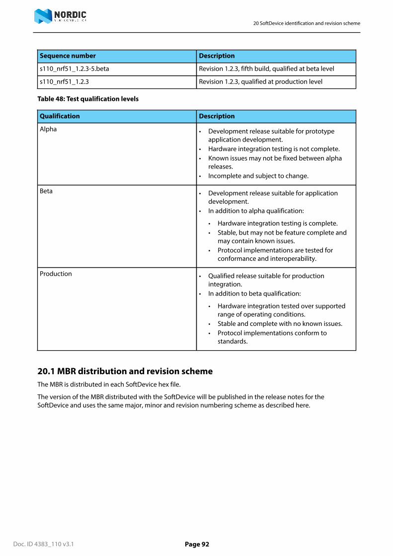
20 SoftDevice identification and revision scheme
Doc. ID 4383_110 v3.1 Page 92
Sequence number Description
s110_nrf51_1.2.3-5.beta Revision 1.2.3, fifth build, qualified at beta level
s110_nrf51_1.2.3 Revision 1.2.3, qualified at production level
Table 48: Test qualification levels
Qualification Description
Alpha • Development release suitable for prototypeapplication development.
• Hardware integration testing is not complete.• Known issues may not be fixed between alpha
releases.• Incomplete and subject to change.
Beta • Development release suitable for applicationdevelopment.
• In addition to alpha qualification:
• Hardware integration testing is complete.• Stable, but may not be feature complete and
may contain known issues.• Protocol implementations are tested for
conformance and interoperability.
Production • Qualified release suitable for productionintegration.
• In addition to beta qualification:
• Hardware integration tested over supportedrange of operating conditions.
• Stable and complete with no known issues.• Protocol implementations conform to
standards.
20.1 MBR distribution and revision schemeThe MBR is distributed in each SoftDevice hex file.
The version of the MBR distributed with the SoftDevice will be published in the release notes for theSoftDevice and uses the same major, minor and revision numbering scheme as described here.

All rights reserved.Reproduction in whole or in part is prohibited without the prior written permission of the copyright holder.