Embed Size (px)
Citation preview
Freescale SemiconductorApplication Note
Document Number: AN4024Rev. 1, 11/2010
Contents
Introduction . . . . . . . . . . . . . . . . . . . . . . . . . . . . . . . . . . . 1Back Electromotive Force (Back EMF) . . . . . . . . . . . . . . 2Flyback . . . . . . . . . . . . . . . . . . . . . . . . . . . . . . . . . . . . . . 4Stall Detection Using Flyback Time. . . . . . . . . . . . . . . . . 5S12HY Family Implementation . . . . . . . . . . . . . . . . . . . . 9
5.1 S12HY Family Pin Configuration. . . . . . . . . . . . . . . 95.2 Coil Current Flow with the S12HY Family . . . . . . . 105.3 Measuring Flyback Time Using S12HY. . . . . . . . . 11S12HY Hardware Implementation . . . . . . . . . . . . . . . . . 15
6.1 Motor Controller. . . . . . . . . . . . . . . . . . . . . . . . . . . 166.2 Timer . . . . . . . . . . . . . . . . . . . . . . . . . . . . . . . . . . . 196.3 Port Integration Module . . . . . . . . . . . . . . . . . . . . . 22Hints and Tips for Usage . . . . . . . . . . . . . . . . . . . . . . . . 24
7.1 Flyback Measurement Conditions . . . . . . . . . . . . . 247.2 When to Sample the Flyback. . . . . . . . . . . . . . . . . 257.3 Determining Coil Current and Flyback Polarity . . . 267.4 Releasing the Motor Coil . . . . . . . . . . . . . . . . . . . . 287.5 Stall Detection and Motor Speed. . . . . . . . . . . . . . 287.6 Characterization . . . . . . . . . . . . . . . . . . . . . . . . . . 307.7 Other S12HY implementation tips . . . . . . . . . . . . . 31Summary . . . . . . . . . . . . . . . . . . . . . . . . . . . . . . . . . . . . 32
S12HY and S12XHY Stepper Stall Detect
by: Pete PinewskiJeff ReiterGordon Borland, Microcontroller Solutions Group. Auto R & D
1 IntroductionStepper motors are used in a wide variety of applications. Many of these applications need to detect when the motor has reached a known position or if its movement is impeded. One example is the synchronization of the pointer position on an instrument gauge.
Methods for synchronization can vary, but some commonly used techniques are based on sensing Back EMF during full step control of the motor. Stepper stall detection methods utilizing full step control may have several drawbacks.
• Detection is limited to a full step or quarter-turn of the motor.
• Mechanical oscillations of full step movement can dictate detection speeds and can appear as choppy pointer movement during slower speeds.
• Slow motor speeds may be necessary to avoid false detection.
12345
6
7
8
© Freescale Semiconductor, Inc., 2010. All rights reserved.
Back Electromotive Force (Back EMF)
• Hardware overhead may be required (Peak Detector, Integrator and so on)
This application note describes a technique to perform high speed stall detection whilst micro-stepping a motor by measuring the Flyback time. This technique, overcomes many of the drawbacks associated with traditional Back EMF sensing during full step movement.
• Detection is possible on micro-step resolution.
• Mechanical oscillations are minimized resulting in smoother pointer movement and wider range of detection speed possibilities.
• Minimal hardware overhead is required (simple input capture).
NOTE
The techniques described in this application note are applicable to both the S12HY and S12XHY microcontrollers. Where S12HY has been referenced, the statement is also true for the S12XHY.
2 Back Electromotive Force (Back EMF)Understanding the basics of stall detection requires knowledge of some motor basics.
When a current flows through a coil, it induces a magnetic field in the coil. This magnetic field in conjunction with the magnetic field generated by the rotor magnets, enables the motor to move. That is, the generation of alternating fields in the motor coils (full stepping) produces a rotating magnetic field in the stator causing rotation of the rotor. This is also true in reverse, movement in the rotor causes a change in the magnetic field of the stator coil, which results in an induced current (and voltage) in the stator coil. This phenomenon known as Back EMF can be seen in an electric motor if the voltage across one of its coils is measured, whilst the motor is still turning.
Stall detection utilizing Back EMF sensing relies on this fact and can be used to detect whether a motor is stalled or not by simply measuring if there is a voltage present on a coil. If the motor is moving, there will be a voltage across the terminals of the coil. If the motor is stalled, no voltage will be present.
An advantage of Back EMF sensing is that no additional wiring is required. The same two wires that drive the coil can be used to measure the Back EMF. By waiting until a point where the coil is not driven or momentarily stopping the PWM signal, the coil circuit can be opened, allowed to float, and the Back EMF voltage can be measured. This relies on the fact that the rotor inertia will keep the motor moving.
One phase full step control lends itself well to Back EMF sensing because only one coil normally has a voltage associated with it while the other coil can be opened for Back EMF sensing.
S12HY and S12XHY Stepper Stall Detect, Rev. 1
Freescale Semiconductor2
Back Electromotive Force (Back EMF)
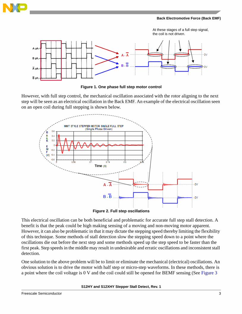
Figure 1. One phase full step motor control
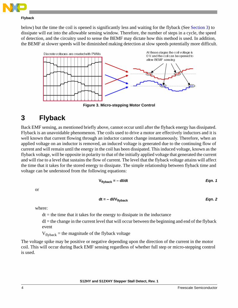
However, with full step control, the mechanical oscillation associated with the rotor aligning to the next step will be seen as an electrical oscillation in the Back EMF. An example of the electrical oscillation seen on an open coil during full stepping is shown below.
Figure 2. Full step oscillations
This electrical oscillation can be both beneficial and problematic for accurate full step stall detection. A benefit is that the peak could be high making sensing of a moving and non-moving motor apparent. However, it can also be problematic in that it may dictate the stepping speed thereby limiting the flexibility of this technique. Some methods of stall detection slow the stepping speed down to a point where the oscillations die out before the next step and some methods speed up the step speed to be faster than the first peak. Step speeds in the middle may result in undesirable and erratic oscillations and inconsistent stall detection.
One solution to the above problem will be to limit or eliminate the mechanical (electrical) oscillations. An obvious solution is to drive the motor with half step or micro-step waveforms. In these methods, there is a point where the coil voltage is 0 V and the coil could still be opened for BEMF sensing (See Figure 3
At these stages of a full step signal, the coil is not driven.
S12HY and S12XHY Stepper Stall Detect, Rev. 1
Freescale Semiconductor 3
Flyback
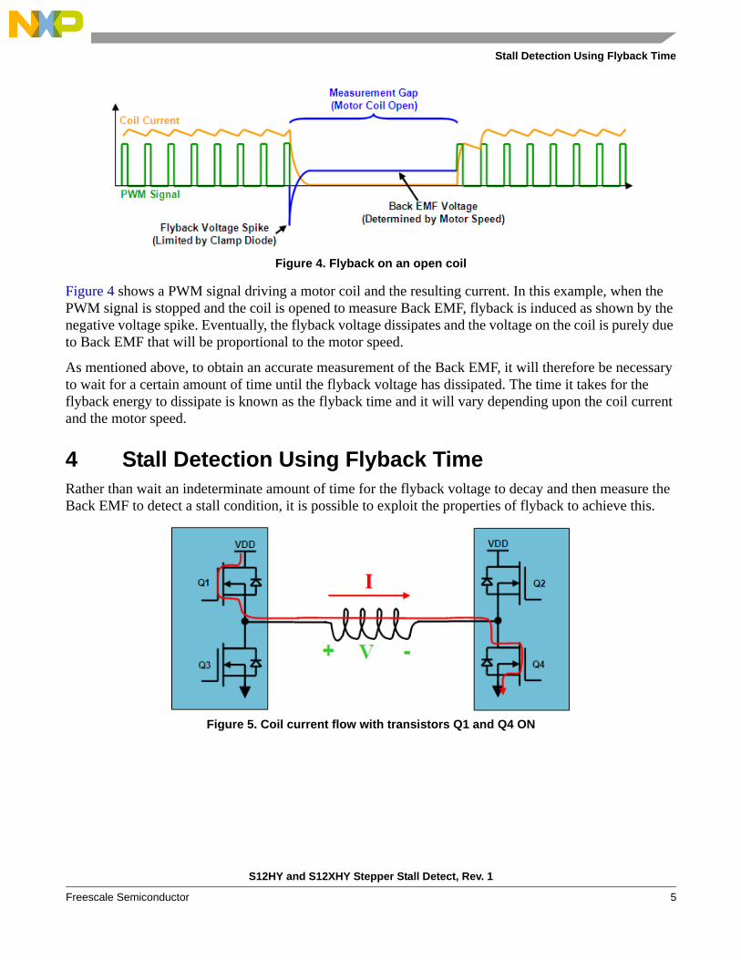
below) but the time the coil is opened is significantly less and waiting for the flyback (See Section 3) to dissipate will eat into the allowable sensing window. Therefore, the number of steps in a cycle, the speed of detection, and the circuitry used to sense the BEMF may dictate how this method is used. In addition, the BEMF at slower speeds will be diminished making detection at slow speeds potentially more difficult.
Figure 3. Micro-stepping Motor Control
3 FlybackBack EMF sensing, as mentioned briefly above, cannot occur until after the flyback energy has dissipated. Flyback is an unavoidable phenomenon. The coils used to drive a motor are effectively inductors and it is well known that current flowing through an inductor cannot change instantaneously. Therefore, when an applied voltage on an inductor is removed, an induced voltage is generated due to the continuing flow of current and will remain until the energy in the coil has been dissipated. This induced voltage, known as the flyback voltage, will be opposite in polarity to that of the initially applied voltage that generated the current and will rise to a level that sustains the flow of current. The level that the flyback voltage attains will affect the time that it takes for the stored energy to dissipate. The simple relationship between flyback time and voltage can be understood from the following equations:
Vflyback = – dI/dt Eqn. 1
or
dt = – dI/Vflyback Eqn. 2
where:
dt = the time that it takes for the energy to dissipate in the inductance
dI = the change in the current level that will occur between the beginning and end of the flyback event
Vflyback = the magnitude of the flyback voltage
The voltage spike may be positive or negative depending upon the direction of the current in the motor coil. This will occur during Back EMF sensing regardless of whether full step or micro-stepping control is used.
S12HY and S12XHY Stepper Stall Detect, Rev. 1
Freescale Semiconductor4
Stall Detection Using Flyback Time
Figure 4. Flyback on an open coil
Figure 4 shows a PWM signal driving a motor coil and the resulting current. In this example, when the PWM signal is stopped and the coil is opened to measure Back EMF, flyback is induced as shown by the negative voltage spike. Eventually, the flyback voltage dissipates and the voltage on the coil is purely due to Back EMF that will be proportional to the motor speed.
As mentioned above, to obtain an accurate measurement of the Back EMF, it will therefore be necessary to wait for a certain amount of time until the flyback voltage has dissipated. The time it takes for the flyback energy to dissipate is known as the flyback time and it will vary depending upon the coil current and the motor speed.
4 Stall Detection Using Flyback TimeRather than wait an indeterminate amount of time for the flyback voltage to decay and then measure the Back EMF to detect a stall condition, it is possible to exploit the properties of flyback to achieve this.
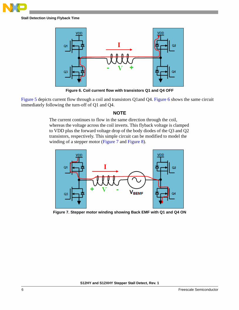
Figure 5. Coil current flow with transistors Q1 and Q4 ON
S12HY and S12XHY Stepper Stall Detect, Rev. 1
Freescale Semiconductor 5
Stall Detection Using Flyback Time
Figure 6. Coil current flow with transistors Q1 and Q4 OFF
Figure 5 depicts current flow through a coil and transistors Q1and Q4. Figure 6 shows the same circuit immediately following the turn-off of Q1 and Q4.
NOTE
The current continues to flow in the same direction through the coil, whereas the voltage across the coil inverts. This flyback voltage is clamped to VDD plus the forward voltage drop of the body diodes of the Q3 and Q2 transistors, respectively. This simple circuit can be modified to model the winding of a stepper motor (Figure 7 and Figure 8).
Figure 7. Stepper motor winding showing Back EMF with Q1 and Q4 ON
S12HY and S12XHY Stepper Stall Detect, Rev. 1
Freescale Semiconductor6
Stall Detection Using Flyback Time
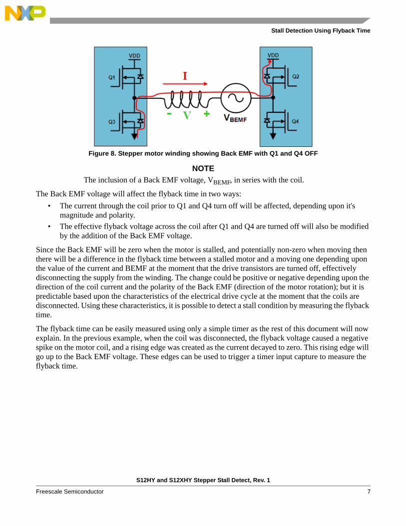
Figure 8. Stepper motor winding showing Back EMF with Q1 and Q4 OFF
NOTE
The inclusion of a Back EMF voltage, VBEMF, in series with the coil.
The Back EMF voltage will affect the flyback time in two ways:
• The current through the coil prior to Q1 and Q4 turn off will be affected, depending upon it's magnitude and polarity.
• The effective flyback voltage across the coil after Q1 and Q4 are turned off will also be modified by the addition of the Back EMF voltage.
Since the Back EMF will be zero when the motor is stalled, and potentially non-zero when moving then there will be a difference in the flyback time between a stalled motor and a moving one depending upon the value of the current and BEMF at the moment that the drive transistors are turned off, effectively disconnecting the supply from the winding. The change could be positive or negative depending upon the direction of the coil current and the polarity of the Back EMF (direction of the motor rotation); but it is predictable based upon the characteristics of the electrical drive cycle at the moment that the coils are disconnected. Using these characteristics, it is possible to detect a stall condition by measuring the flyback time.
The flyback time can be easily measured using only a simple timer as the rest of this document will now explain. In the previous example, when the coil was disconnected, the flyback voltage caused a negative spike on the motor coil, and a rising edge was created as the current decayed to zero. This rising edge will go up to the Back EMF voltage. These edges can be used to trigger a timer input capture to measure the flyback time.
S12HY and S12XHY Stepper Stall Detect, Rev. 1
Freescale Semiconductor 7
Stall Detection Using Flyback Time
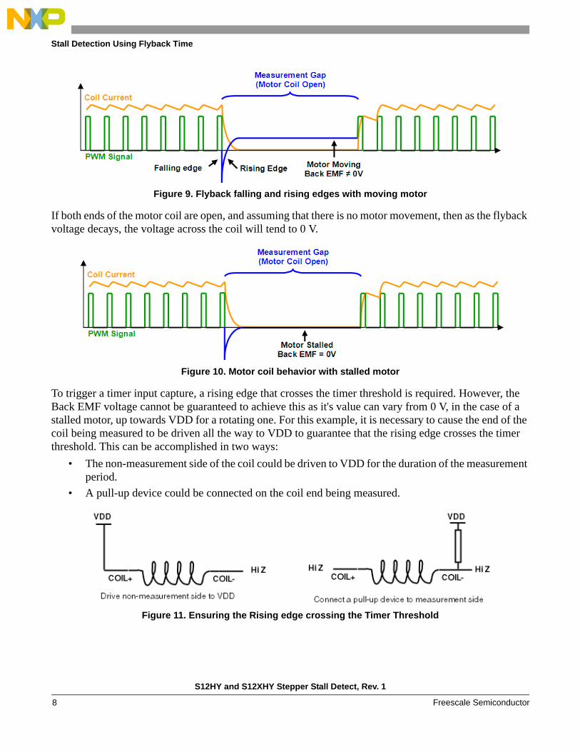
Figure 9. Flyback falling and rising edges with moving motor
If both ends of the motor coil are open, and assuming that there is no motor movement, then as the flyback voltage decays, the voltage across the coil will tend to 0 V.
Figure 10. Motor coil behavior with stalled motor
To trigger a timer input capture, a rising edge that crosses the timer threshold is required. However, the Back EMF voltage cannot be guaranteed to achieve this as it's value can vary from 0 V, in the case of a stalled motor, up towards VDD for a rotating one. For this example, it is necessary to cause the end of the coil being measured to be driven all the way to VDD to guarantee that the rising edge crosses the timer threshold. This can be accomplished in two ways:
• The non-measurement side of the coil could be driven to VDD for the duration of the measurement period.
• A pull-up device could be connected on the coil end being measured.
Figure 11. Ensuring the Rising edge crossing the Timer Threshold
S12HY and S12XHY Stepper Stall Detect, Rev. 1
Freescale Semiconductor8
S12HY Family Implementation
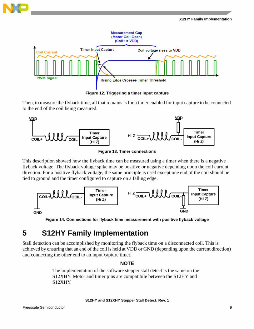
Figure 12. Triggering a timer input capture
Then, to measure the flyback time, all that remains is for a timer enabled for input capture to be connected to the end of the coil being measured.
Figure 13. Timer connections
This description showed how the flyback time can be measured using a timer when there is a negative flyback voltage. The flyback voltage spike may be positive or negative depending upon the coil current direction. For a positive flyback voltage, the same principle is used except one end of the coil should be tied to ground and the timer configured to capture on a falling edge.
Figure 14. Connections for flyback time measurement with positive flyback voltage
5 S12HY Family ImplementationStall detection can be accomplished by monitoring the flyback time on a disconnected coil. This is achieved by ensuring that an end of the coil is held at VDD or GND (depending upon the current direction) and connecting the other end to an input capture timer.
NOTE
The implementation of the software stepper stall detect is the same on the S12XHY. Motor and timer pins are compatibile between the S12HY and S12XHY.
COIL+ COIL-
VDD
Timer Input Capture
(Hi Z) COIL+ COIL-
VDD
Hi ZTimer
Input Capture (Hi Z)
COIL+ COIL-
GND
COIL+ COIL-
GND
Hi ZTimer
Input Capture (Hi Z)
Timer Input Capture
(Hi Z)
S12HY and S12XHY Stepper Stall Detect, Rev. 1
Freescale Semiconductor 9
S12HY Family Implementation
The technique is basically as follows:
1. Disconnect the coil
2. Force an end of the coil to VDD or GND
3. Connect an input capture timer to the coil
4. Wait for an input capture event to trigger
5. Reconnect the coil
6. Calculate the flyback time
5.1 S12HY Family Pin Configuration
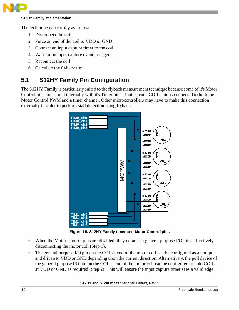
The S12HY Family is particularly suited to the flyback measurement technique because some of it's Motor Control pins are shared internally with it's Timer pins. That is, each COIL- pin is connected to both the Motor Control PWM and a timer channel. Other microcontrollers may have to make this connection externally in order to perform stall detection using flyback.
Figure 15. S12HY Family timer and Motor Control pins
• When the Motor Control pins are disabled, they default to general purpose I/O pins, effectively disconnecting the motor coil (Step 1).
• The general purpose I/O pin on the COIL+ end of the motor coil can be configured as an output and driven to VDD or GND depending upon the current direction. Alternatively, the pull device of the general purpose I/O pin on the COIL– end of the motor coil can be configured to hold COIL– at VDD or GND as required (Step 2). This will ensure the input capture timer sees a valid edge.
TIM0_ch0
MC
PW
M
M0C0M
M0C0P
M0C1M
M0C1P
M1C0M
M1C0P
M1C1M
M1C1P
TIM0_ch1TIM0_ch2TIM0_ch3
M2C0M
M2C0P
M2C1M
M2C1P
M3C0M
M3C0P
M3C1M
M3C1P
TIM1_ch0TIM1_ch1TIM1_ch2TIM1_ch3
TIM0_ch0M
CP
WM
M0C0M
M0C0P
M0C1M
M0C1P
M1C0M
M1C0P
M1C1M
M1C1P
TIM0_ch1TIM0_ch2TIM0_ch3
M2C0M
M2C0P
M2C1M
M2C1P
M3C0M
M3C0P
M3C1M
M3C1P
TIM1_ch0TIM1_ch1TIM1_ch2TIM1_ch3
S12HY and S12XHY Stepper Stall Detect, Rev. 1
Freescale Semiconductor10
S12HY Family Implementation
• The timer channel on COIL– can be enabled as a timer input capture on a rising or falling edge depending upon the current direction (Step 3).
• Once a valid edge has been detected, the timer and the general purpose I/O pin can be disabled, and the Motor Control pins are re-enabled. On the S12HY Family, the motor control function takes priority over the timer and general purpose I/O functionality (Step 4).
• Re-enabling the motor control effectively disables the timer and general purpose I/O and reconnects the motor coil (Step 5).
• Software can then read the captured timer value, calculate the flyback time and determine whether a stall condition is present (Step 6).
5.2 Coil Current Flow with the S12HY Family
The edges used by the timer to measure flyback time depend upon the polarity of the flyback voltage. This is determined by the direction of the coil current and which side of the coil is used to perform the measurement. On the S12HY Family, this will always be the COIL– due to the pin configuration of the microcontroller.
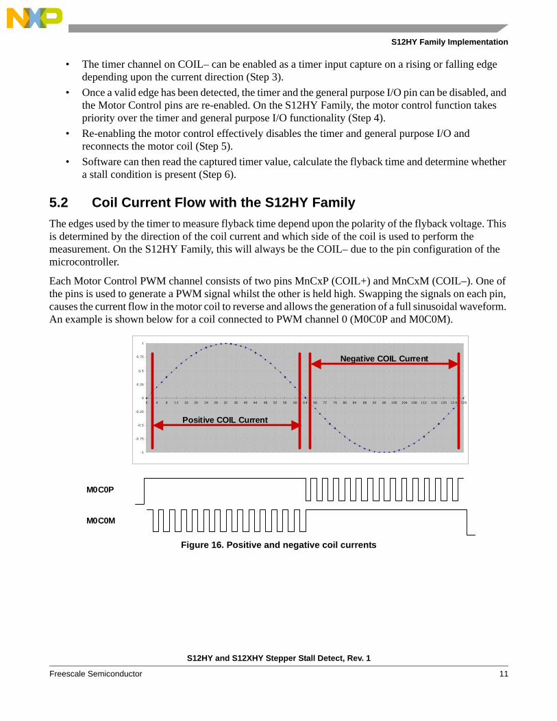
Each Motor Control PWM channel consists of two pins MnCxP (COIL+) and MnCxM (COIL–). One of the pins is used to generate a PWM signal whilst the other is held high. Swapping the signals on each pin, causes the current flow in the motor coil to reverse and allows the generation of a full sinusoidal waveform. An example is shown below for a coil connected to PWM channel 0 (M0C0P and M0C0M).
Figure 16. Positive and negative coil currents
-1
-0.75
-0.5
-0.25
0
0.25
0.5
0.75
1
0 4 8 1 2 16 20 24 28 32 36 40 44 48 52 56 60 6 4 68 72 76 80 84 88 92 96 100 104 108 112 116 120 12 4 128
Negative COIL Current
Positive COIL Current
M0C0P
M0C0M
S12HY and S12XHY Stepper Stall Detect, Rev. 1
Freescale Semiconductor 11
S12HY Family Implementation
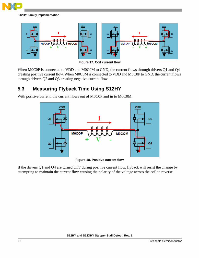
Figure 17. Coil current flow
When M0C0P is connected to VDD and M0C0M to GND, the current flows through drivers Q1 and Q4 creating positive current flow. When M0C0M is connected to VDD and M0C0P to GND, the current flows through drivers Q2 and Q3 creating negative current flow.
5.3 Measuring Flyback Time Using S12HY
With positive current, the current flows out of M0C0P and in to M0C0M.
Figure 18. Positive current flow
If the drivers Q1 and Q4 are turned OFF during positive current flow, flyback will resist the change by attempting to maintain the current flow causing the polarity of the voltage across the coil to reverse.
S12HY and S12XHY Stepper Stall Detect, Rev. 1
Freescale Semiconductor12
S12HY Family Implementation
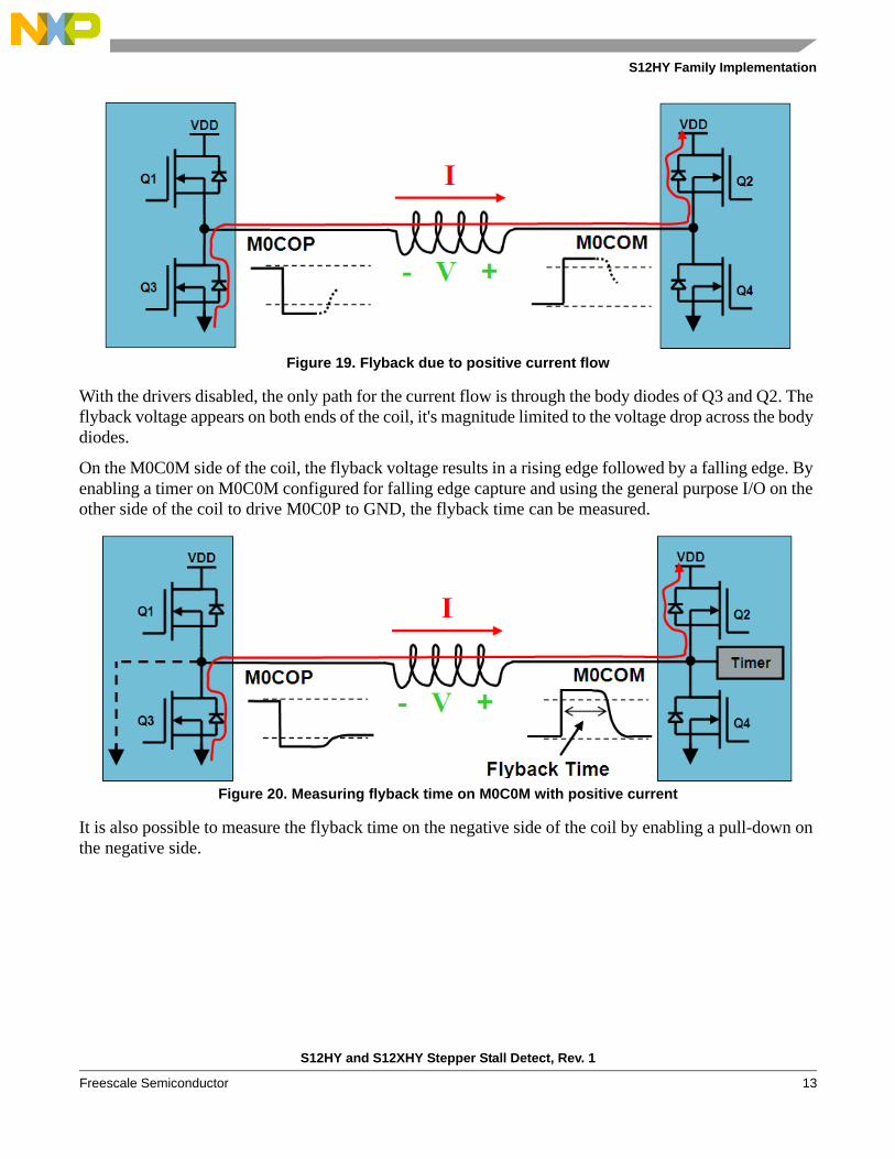
Figure 19. Flyback due to positive current flow
With the drivers disabled, the only path for the current flow is through the body diodes of Q3 and Q2. The flyback voltage appears on both ends of the coil, it's magnitude limited to the voltage drop across the body diodes.
On the M0C0M side of the coil, the flyback voltage results in a rising edge followed by a falling edge. By enabling a timer on M0C0M configured for falling edge capture and using the general purpose I/O on the other side of the coil to drive M0C0P to GND, the flyback time can be measured.
Figure 20. Measuring flyback time on M0C0M with positive current
It is also possible to measure the flyback time on the negative side of the coil by enabling a pull-down on the negative side.
S12HY and S12XHY Stepper Stall Detect, Rev. 1
Freescale Semiconductor 13
S12HY Family Implementation
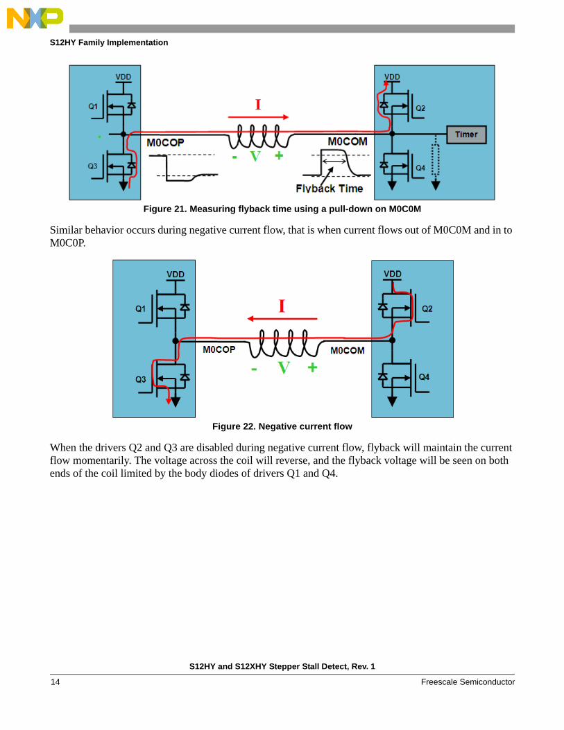
Figure 21. Measuring flyback time using a pull-down on M0C0M
Similar behavior occurs during negative current flow, that is when current flows out of M0C0M and in to M0C0P.
Figure 22. Negative current flow
When the drivers Q2 and Q3 are disabled during negative current flow, flyback will maintain the current flow momentarily. The voltage across the coil will reverse, and the flyback voltage will be seen on both ends of the coil limited by the body diodes of drivers Q1 and Q4.
S12HY and S12XHY Stepper Stall Detect, Rev. 1
Freescale Semiconductor14
S12HY Family Implementation
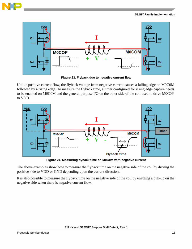
Figure 23. Flyback due to negative current flow
Unlike positive current flow, the flyback voltage from negative current causes a falling edge on M0C0M followed by a rising edge. To measure the flyback time, a timer configured for rising edge capture needs to be enabled on M0C0M and the general purpose I/O on the other side of the coil used to drive M0C0P to VDD.
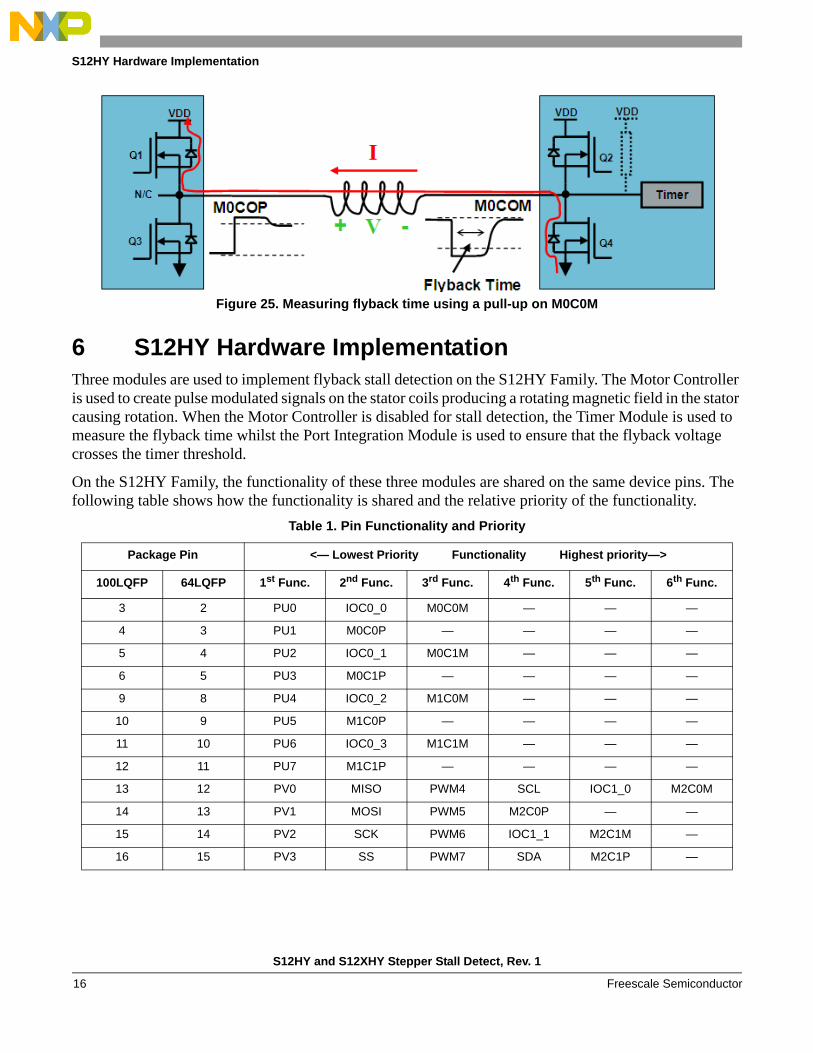
Figure 24. Measuring flyback time on M0C0M with negative current
The above examples show how to measure the flyback time on the negative side of the coil by driving the positive side to VDD or GND depending upon the current direction.
It is also possible to measure the flyback time on the negative side of the coil by enabling a pull-up on the negative side when there is negative current flow.
S12HY and S12XHY Stepper Stall Detect, Rev. 1
Freescale Semiconductor 15
S12HY Hardware Implementation
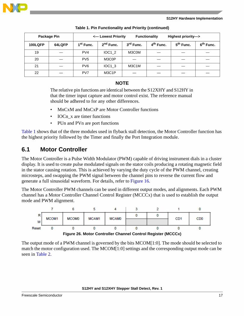
Figure 25. Measuring flyback time using a pull-up on M0C0M
6 S12HY Hardware ImplementationThree modules are used to implement flyback stall detection on the S12HY Family. The Motor Controller is used to create pulse modulated signals on the stator coils producing a rotating magnetic field in the stator causing rotation. When the Motor Controller is disabled for stall detection, the Timer Module is used to measure the flyback time whilst the Port Integration Module is used to ensure that the flyback voltage crosses the timer threshold.
On the S12HY Family, the functionality of these three modules are shared on the same device pins. The following table shows how the functionality is shared and the relative priority of the functionality.
Table 1. Pin Functionality and Priority
Package Pin <— Lowest Priority Functionality Highest priority—>
100LQFP 64LQFP 1st Func. 2nd Func. 3rd Func. 4th Func. 5th Func. 6th Func.
3 2 PU0 IOC0_0 M0C0M — — —
4 3 PU1 M0C0P — — — —
5 4 PU2 IOC0_1 M0C1M — — —
6 5 PU3 M0C1P — — — —
9 8 PU4 IOC0_2 M1C0M — — —
10 9 PU5 M1C0P — — — —
11 10 PU6 IOC0_3 M1C1M — — —
12 11 PU7 M1C1P — — — —
13 12 PV0 MISO PWM4 SCL IOC1_0 M2C0M
14 13 PV1 MOSI PWM5 M2C0P — —
15 14 PV2 SCK PWM6 IOC1_1 M2C1M —
16 15 PV3 SS PWM7 SDA M2C1P —
S12HY and S12XHY Stepper Stall Detect, Rev. 1
Freescale Semiconductor16
S12HY Hardware Implementation
NOTE
The relative pin functions are identical between the S12XHY and S12HY in that the timer input capture and motor control exist. The reference manual should be adhered to for any other differences.
• MnCxM and MnCxP are Motor Controller functions
• IOCn_x are timer functions
• PUn and PVn are port functions
Table 1 shows that of the three modules used in flyback stall detection, the Motor Controller function has the highest priority followed by the Timer and finally the Port Integration module.
6.1 Motor Controller
The Motor Controller is a Pulse Width Modulator (PWM) capable of driving instrument dials in a cluster display. It is used to create pulse modulated signals on the stator coils producing a rotating magnetic field in the stator causing rotation. This is achieved by varying the duty cycle of the PWM channel, creating microsteps, and swapping the PWM signal between the channel pins to reverse the current flow and generate a full sinusoidal waveform. For details, refer to Figure 16.
The Motor Controller PWM channels can be used in different output modes, and alignments. Each PWM channel has a Motor Controller Channel Control Register (MCCCx) that is used to establish the output mode and PWM alignment.
Figure 26. Motor Controller Channel Control Register (MCCCx)
The output mode of a PWM channel is governed by the bits MCOM[1:0]. The mode should be selected to match the motor configuration used. The MCOM[1:0] settings and the corresponding output mode can be seen in Table 2.
19 — PV4 IOC1_2 M3C0M — — —
20 — PV5 M3C0P — — — —
21 — PV6 IOC1_3 M3C1M — — —
22 — PV7 M3C1P — — — —
Table 1. Pin Functionality and Priority (continued)
Package Pin <— Lowest Priority Functionality Highest priority—>
100LQFP 64LQFP 1st Func. 2nd Func. 3rd Func. 4th Func. 5th Func. 6th Func.
S12HY and S12XHY Stepper Stall Detect, Rev. 1
Freescale Semiconductor 17
S12HY Hardware Implementation
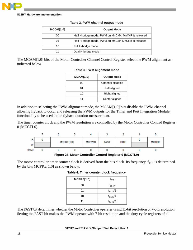
The MCAM[1:0] bits of the Motor Controller Channel Control Register select the PWM alignment as indicated below.
In addition to selecting the PWM alignment mode, the MCAM[1;0] bits disable the PWM channel allowing flyback to occur and releasing the PWM outputs for the Timer and Port Integration Module functionality to be used in the flyback duration measurement.
The timer counter clock and the PWM resolution are controlled by the Motor Controller Control Register 0 (MCCTL0).
Figure 27. Motor Controller Control Register 0 (MCCTL0)
The motor controller timer counter clock is derived from the bus clock. Its frequency, fTC, is determined by the bits MCPRE[1:0] as shown below.
The FAST bit determines whether the Motor Controller operates using 11-bit resolution or 7-bit resolution. Setting the FAST bit makes the PWM operate with 7-bit resolution and the duty cycle registers of all
Table 2. PWM channel output mode
MCOM[1:0] Output Mode
00 Half H-bridge mode, PWM on MnCxM, MnCxP is released
01 Half H-bridge mode, PWM on MnCxP, MnCxM is released
10 Full H-bridge mode
11 Dual H-bridge mode
Table 3. PWM alignment mode
MCAM[1:0] Output Mode
00 Channel disabled
01 Left aligned
10 Right aligned
11 Center aligned
Table 4. Timer counter clock frequency
MCPRE[1:0] fTC
00 fBUS
01 fBUS/2
10 fBUS/4
11 fBUS/8
S12HY and S12XHY Stepper Stall Detect, Rev. 1
Freescale Semiconductor18

S12HY Hardware Implementation
channels are switched to byte access. With the FAST bit clear, the PWM operates with 11-bit resolution and the duty cycle registers of all channels are switched to word access.
When the Motor Controller timer overflows, bit MCTOIF is set, indicating the end of a PWM boundary.
The Motor Controller PWM signal can be either active high or active low. This is selected using the RECIRC bit of the Motor Controller Control Register 1 (MCCTL1).
Figure 28. Motor Controller Control Register 1 (MCCTL1)
Setting the RECIRC bit causes the PWM output to be active high. Otherwise, the PWM output is active low.
The Motor Controller Period Register (MCPER) is used to configure the period of the Motor Controller PWM channels.
Figure 29. Motor Controller Period Register (MCPER)
The content of the Motor Controller Period Register (MCPER) represents the period of the Motor Controller PWM channels in motor controller timer counter clocks.
Each PWM channel has an associated Motor Controller Duty Cycle Register (MCDCx) that is used to configure the duty cycle of the PWM channel. The Motor Controller Duty Cycle Register (MCDCx) can be 11 or 7 bits wide depending upon the PWM resolution mode.
Figure 30. Motor Controller Duty Cycle Register (MCDCx) in 11-bit mode
Figure 31. Motor Controller Duty Cycle Register (MCDCx) in 7-bit mode
The duty cycle bits D[10:0], or D[8:2] depending upon the resolution, define the number of motor controller timer counter clocks that a PWM output is active.
S12HY and S12XHY Stepper Stall Detect, Rev. 1
Freescale Semiconductor 19
S12HY Hardware Implementation
Each different duty cycle represents a different micro-step. Changing the duty cycle will change the current flowing through the coil causing a change in the magnetic field of the stator and induce movement of the rotor.
The S bit of the Motor Controller Duty Cycle Register determines which PWM channel output the PWM signal appears on. By swapping the PWM signal between the PWM channel outputs, the coil current direction can be reversed.
Together the duty cycle bits and the S bit can be used to approximate a full sinusoidal waveform.
The frequency or speed of the motor can be varied either by changing the PWM period, or by varying the number of micro-steps used to approximate a sinusoidal waveform.
6.2 Timer
The Timer Module is used to measure the flyback time. A rising or falling edge triggers an input capture event causing the timer to latch the value of it's counter into a register. By subtracting the value of the counter at the beginning of the flyback measurement from the latched counter value, the flyback time can be calculated. To evaluate whether a stall condition exists the flyback time is compared against a set of pre-determined limits.
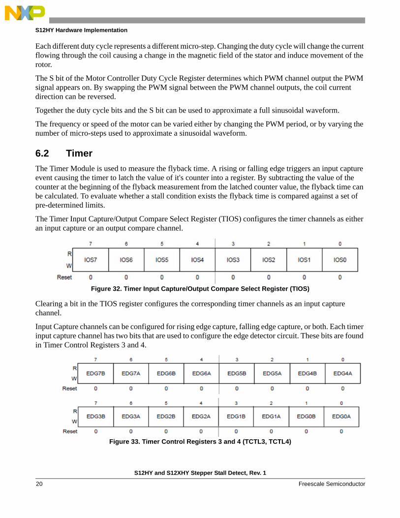
The Timer Input Capture/Output Compare Select Register (TIOS) configures the timer channels as either an input capture or an output compare channel.
Figure 32. Timer Input Capture/Output Compare Select Register (TIOS)
Clearing a bit in the TIOS register configures the corresponding timer channels as an input capture channel.
Input Capture channels can be configured for rising edge capture, falling edge capture, or both. Each timer input capture channel has two bits that are used to configure the edge detector circuit. These bits are found in Timer Control Registers 3 and 4.
Figure 33. Timer Control Registers 3 and 4 (TCTL3, TCTL4)
S12HY and S12XHY Stepper Stall Detect, Rev. 1
Freescale Semiconductor20
S12HY Hardware Implementation
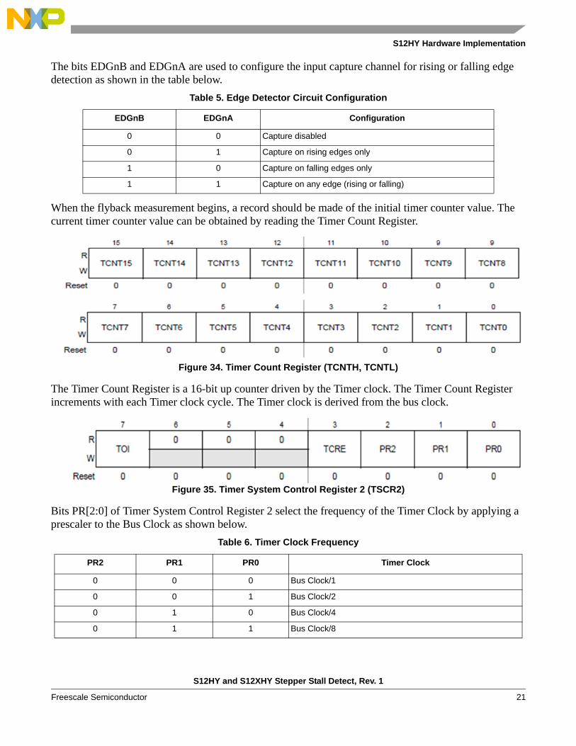
The bits EDGnB and EDGnA are used to configure the input capture channel for rising or falling edge detection as shown in the table below.
When the flyback measurement begins, a record should be made of the initial timer counter value. The current timer counter value can be obtained by reading the Timer Count Register.
Figure 34. Timer Count Register (TCNTH, TCNTL)
The Timer Count Register is a 16-bit up counter driven by the Timer clock. The Timer Count Register increments with each Timer clock cycle. The Timer clock is derived from the bus clock.
Figure 35. Timer System Control Register 2 (TSCR2)
Bits PR[2:0] of Timer System Control Register 2 select the frequency of the Timer Clock by applying a prescaler to the Bus Clock as shown below.
Table 5. Edge Detector Circuit Configuration
EDGnB EDGnA Configuration
0 0 Capture disabled
0 1 Capture on rising edges only
1 0 Capture on falling edges only
1 1 Capture on any edge (rising or falling)
Table 6. Timer Clock Frequency
PR2 PR1 PR0 Timer Clock
0 0 0 Bus Clock/1
0 0 1 Bus Clock/2
0 1 0 Bus Clock/4
0 1 1 Bus Clock/8
S12HY and S12XHY Stepper Stall Detect, Rev. 1
Freescale Semiconductor 21

S12HY Hardware Implementation
Each Timer channel has a pair of registers that latch the value of the Timer counter when a valid input capture or output compare event occurs.
Figure 36. Timer Input Capture / Output Compare Register (TCxH, TCxL)
When the flyback voltage crosses the threshold of the timer input capture, the counter value is latched into the Timer Input Capture / Output Compare Registers of the corresponding Timer Channel. The flyback time, in Timer clock cycles, is the difference between the latched counter value in TCxH, TCxL, and the initial counter value recorded at the beginning of the flyback measurement.
When an input capture event occurs on a timer channel, a corresponding flag is set in the Main Timer Interrupt Flag 1 Register.
Figure 37. Main Timer Interrupt Flag 1 Register (TFLG1)
The flags are cleared by writing 1 to the set flag bit.
Rather than polling the input capture flags to identify when an input capture has occurred, an interrupt can be enabled. To enable an interrupt for a particular timer input capture channel, set the corresponding bit in the Timer Interrupt Enable Register. When a valid edge is detected on the timer input capture channel, the resulting interrupt will notify software that a valid input capture event has occurred.
1 0 0 Bus Clock/16
1 0 1 Bus Clock/32
1 1 0 Bus Clock/64
1 1 1 Bus Clock/128
Table 6. Timer Clock Frequency (continued)
PR2 PR1 PR0 Timer Clock
S12HY and S12XHY Stepper Stall Detect, Rev. 1
Freescale Semiconductor22
S12HY Hardware Implementation
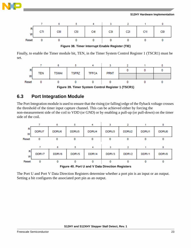
Figure 38. Timer Interrupt Enable Register (TIE)
Finally, to enable the Timer module bit, TEN, in the Timer System Control Register 1 (TSCR1) must be set.
Figure 39. Timer System Control Register 1 (TSCR1)
6.3 Port Integration Module
The Port Integration module is used to ensure that the rising (or falling) edge of the flyback voltage crosses the threshold of the timer input capture channel. This can be achieved either by forcing the non-measurement side of the coil to VDD (or GND) or by enabling a pull-up (or pull-down) on the timer side of the coil.
Figure 40. Port U and V Data Direction Registers
The Port U and Port V Data Direction Registers determine whether a port pin is an input or an output. Setting a bit configures the associated port pin as an output.
S12HY and S12XHY Stepper Stall Detect, Rev. 1
Freescale Semiconductor 23
S12HY Hardware Implementation
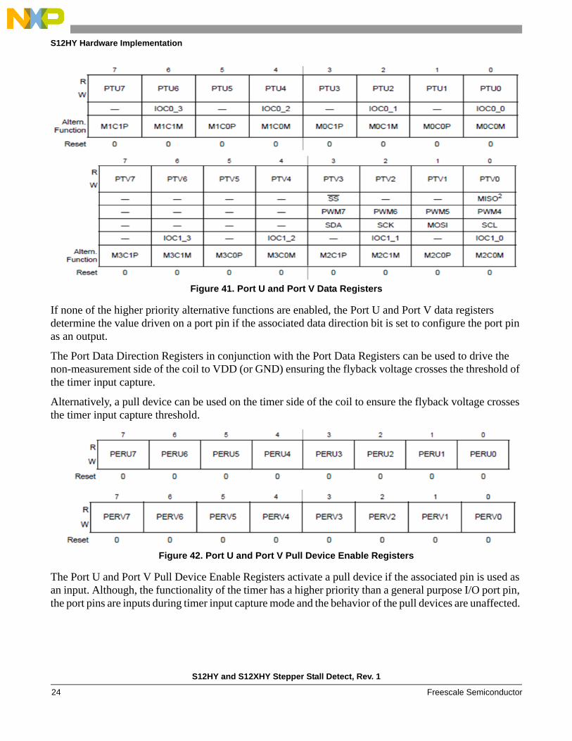
Figure 41. Port U and Port V Data Registers
If none of the higher priority alternative functions are enabled, the Port U and Port V data registers determine the value driven on a port pin if the associated data direction bit is set to configure the port pin as an output.
The Port Data Direction Registers in conjunction with the Port Data Registers can be used to drive the non-measurement side of the coil to VDD (or GND) ensuring the flyback voltage crosses the threshold of the timer input capture.
Alternatively, a pull device can be used on the timer side of the coil to ensure the flyback voltage crosses the timer input capture threshold.
Figure 42. Port U and Port V Pull Device Enable Registers
The Port U and Port V Pull Device Enable Registers activate a pull device if the associated pin is used as an input. Although, the functionality of the timer has a higher priority than a general purpose I/O port pin, the port pins are inputs during timer input capture mode and the behavior of the pull devices are unaffected.
S12HY and S12XHY Stepper Stall Detect, Rev. 1
Freescale Semiconductor24
Hints and Tips for Usage
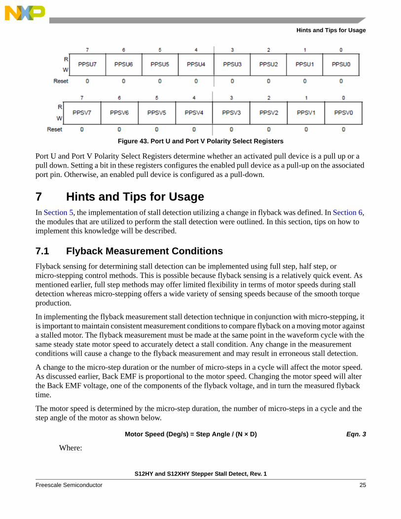
Figure 43. Port U and Port V Polarity Select Registers
Port U and Port V Polarity Select Registers determine whether an activated pull device is a pull up or a pull down. Setting a bit in these registers configures the enabled pull device as a pull-up on the associated port pin. Otherwise, an enabled pull device is configured as a pull-down.
7 Hints and Tips for UsageIn Section 5, the implementation of stall detection utilizing a change in flyback was defined. In Section 6, the modules that are utilized to perform the stall detection were outlined. In this section, tips on how to implement this knowledge will be described.
7.1 Flyback Measurement Conditions
Flyback sensing for determining stall detection can be implemented using full step, half step, or micro-stepping control methods. This is possible because flyback sensing is a relatively quick event. As mentioned earlier, full step methods may offer limited flexibility in terms of motor speeds during stall detection whereas micro-stepping offers a wide variety of sensing speeds because of the smooth torque production.
In implementing the flyback measurement stall detection technique in conjunction with micro-stepping, it is important to maintain consistent measurement conditions to compare flyback on a moving motor against a stalled motor. The flyback measurement must be made at the same point in the waveform cycle with the same steady state motor speed to accurately detect a stall condition. Any change in the measurement conditions will cause a change to the flyback measurement and may result in erroneous stall detection.
A change to the micro-step duration or the number of micro-steps in a cycle will affect the motor speed. As discussed earlier, Back EMF is proportional to the motor speed. Changing the motor speed will alter the Back EMF voltage, one of the components of the flyback voltage, and in turn the measured flyback time.
The motor speed is determined by the micro-step duration, the number of micro-steps in a cycle and the step angle of the motor as shown below.
Motor Speed (Deg/s) = Step Angle / (N × D) Eqn. 3
Where:
S12HY and S12XHY Stepper Stall Detect, Rev. 1
Freescale Semiconductor 25

Hints and Tips for Usage
Step Angle = Number of Degrees Movement per Electrical Cycle
N = Number of Micro-steps per Electrical Cycle
D = Duration of one Micro-step
The Back EMF voltage also varies in relation to the coil waveform cycle (See Figure 44). Different points of the cycle have different Back EMF voltages. If the sampling point changes, then the Back EMF voltage will change also. It is therefore important to ensure that the sampling of flyback occurs at the same point in each waveform cycle.
The period of the waveform cycle is governed by the number of micro-steps per cycle, and the duration of each micro-step.
Waveform Cycle Period = N × D Eqn. 4
Where:
N = Number of Micro-steps per Electrical Cycle
D = Duration of one Micro-step
Waiting one Waveform Cycle Period before making the next flyback measurement ensures that the measurement is made at the same point in each waveform cycle. However, there are four points in the waveform cycle that would have the same flyback value (See Figure 44).
Table 7 shows some examples of how the micro-step duration and the number of micro-steps in a cycle affect the motor speed and the Waveform Cycle Period for a motor that has a 2 degrees step angle.
7.2 When to Sample the Flyback
Normally, the best time to open the motor coil and sample the flyback is when the drive voltage is 0 V. However, because flyback measurement technique takes very little time, the step at which flyback sampling is performed can be chosen to be any point in the generated waveform as long as it is consistent from cycle to cycle. Ideally, the point chosen would be when the BEMF signal is at its peak to ensure the greatest change in the flyback time. As illustrated in the simulation below, it just happens that the peak BEMF coincides approximately with the 0 V step.
Table 7. Effect of Micro-Steps and Micro-Step duration on Motor Speed and Cycle Period
µStep Time (ms)
µSteps / cycle
MotorSpeed(Deg/s)
Cycle Period(ms)
µStep Time (ms)
µSteps / cycle
MotorSpeed(Deg/s)
Cycle Period (ms)
µStep Time (ms)
µSteps / cycle
MotorSpeed(Deg/s)
Cycle Period (ms)
0.5 8 500.0 4 0.5 16 250.0 8 0.5 32 125.0 16
1 8 250.0 8 1 16 125.0 16 1 32 62.5 32
2 8 125.0 16 2 16 62.5 32 2 32 31.3 64
3 8 83.3 24 3 16 41.7 48 3 32 20.8 96
4 8 62.5 32 4 16 31.3 64 4 32 15.6 128
S12HY and S12XHY Stepper Stall Detect, Rev. 1
Freescale Semiconductor26
Hints and Tips for Usage
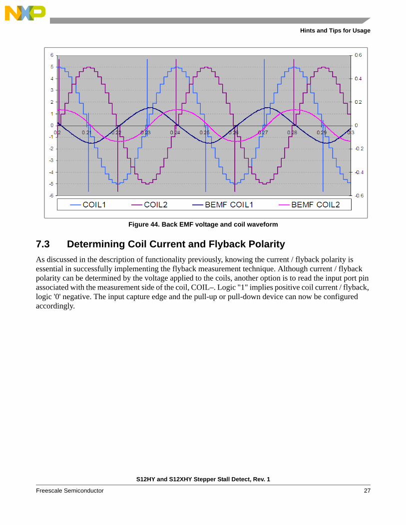
Figure 44. Back EMF voltage and coil waveform
7.3 Determining Coil Current and Flyback Polarity
As discussed in the description of functionality previously, knowing the current / flyback polarity is essential in successfully implementing the flyback measurement technique. Although current / flyback polarity can be determined by the voltage applied to the coils, another option is to read the input port pin associated with the measurement side of the coil, COIL–. Logic "1" implies positive coil current / flyback, logic '0' negative. The input capture edge and the pull-up or pull-down device can now be configured accordingly.
S12HY and S12XHY Stepper Stall Detect, Rev. 1
Freescale Semiconductor 27
Hints and Tips for Usage
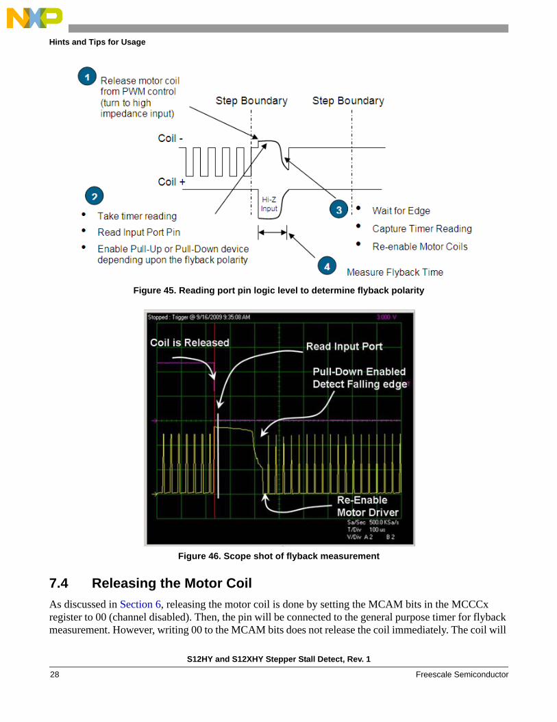
Figure 45. Reading port pin logic level to determine flyback polarity
Figure 46. Scope shot of flyback measurement
7.4 Releasing the Motor Coil
As discussed in Section 6, releasing the motor coil is done by setting the MCAM bits in the MCCCx register to 00 (channel disabled). Then, the pin will be connected to the general purpose timer for flyback measurement. However, writing 00 to the MCAM bits does not release the coil immediately. The coil will
S12HY and S12XHY Stepper Stall Detect, Rev. 1
Freescale Semiconductor28
Hints and Tips for Usage
not be released until a PWM boundary is reached. Therefore, after setting the MCAM bits to 00, it is necessary to monitor the MCOTIF bit (PWM overflow flag) in the MCCTL0 register.
See example code below:
7.5 Stall Detection and Motor Speed
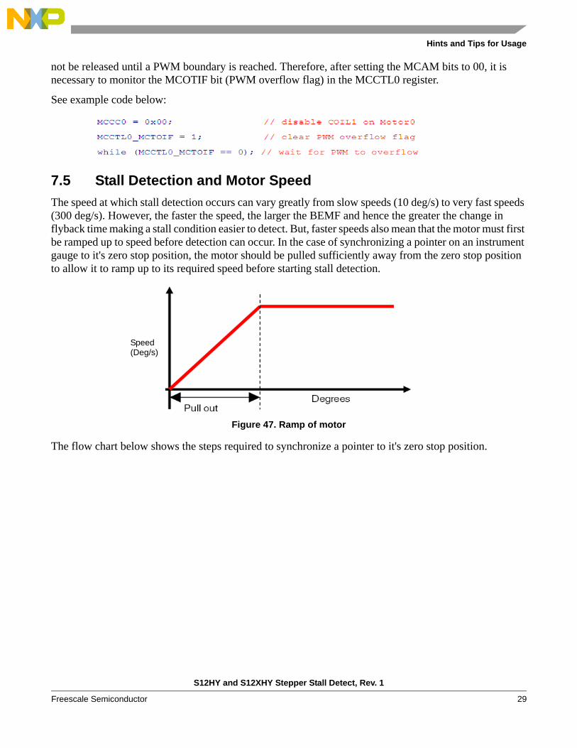
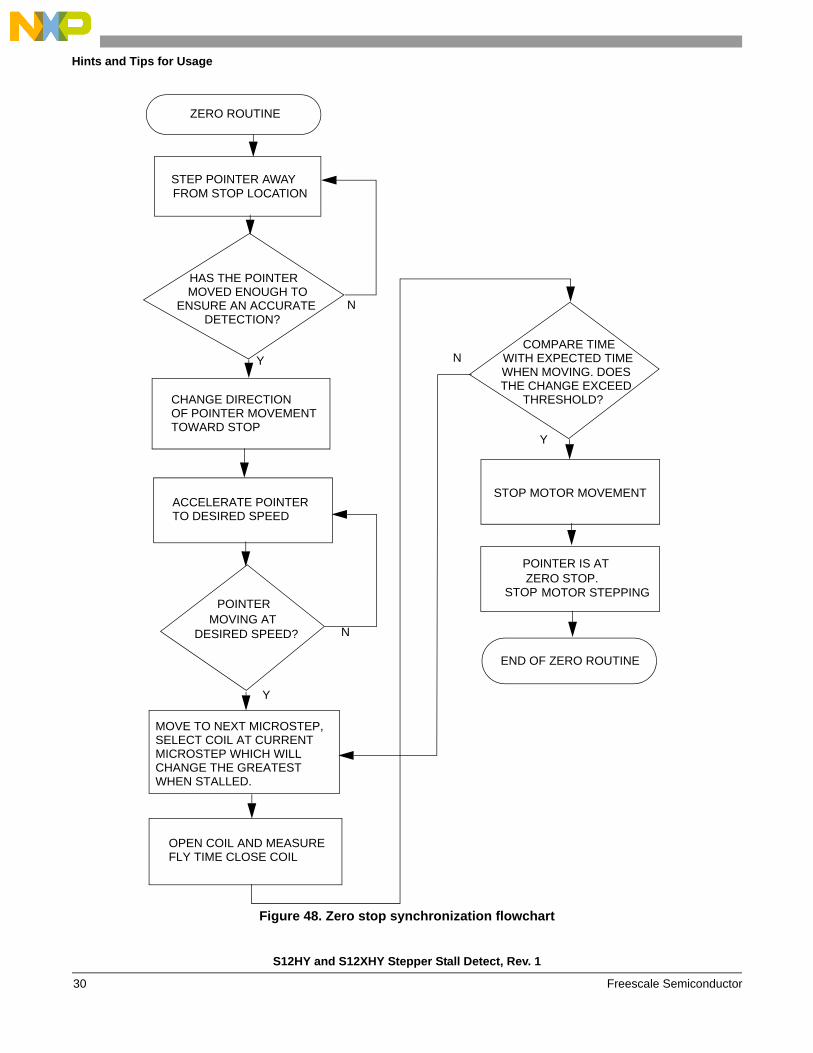
The speed at which stall detection occurs can vary greatly from slow speeds (10 deg/s) to very fast speeds (300 deg/s). However, the faster the speed, the larger the BEMF and hence the greater the change in flyback time making a stall condition easier to detect. But, faster speeds also mean that the motor must first be ramped up to speed before detection can occur. In the case of synchronizing a pointer on an instrument gauge to it's zero stop position, the motor should be pulled sufficiently away from the zero stop position to allow it to ramp up to its required speed before starting stall detection.
Figure 47. Ramp of motor
The flow chart below shows the steps required to synchronize a pointer to it's zero stop position.
Speed(Deg/s)
S12HY and S12XHY Stepper Stall Detect, Rev. 1
Freescale Semiconductor 29
Hints and Tips for Usage
Figure 48. Zero stop synchronization flowchart
ZERO ROUTINE
STEP POINTER AWAY FROM STOP LOCATION
HAS THE POINTER MOVED ENOUGH TO
ENSURE AN ACCURATE DETECTION?
CHANGE DIRECTION OF POINTER MOVEMENT TOWARD STOP
ACCELERATE POINTER TO DESIRED SPEED
POINTER MOVING AT
DESIRED SPEED?
MOVE TO NEXT MICROSTEP, SELECT COIL AT CURRENT MICROSTEP WHICH WILL CHANGE THE GREATEST WHEN STALLED.
OPEN COIL AND MEASURE FLY TIME CLOSE COIL
COMPARE TIME WITH EXPECTED TIME WHEN MOVING. DOES THE CHANGE EXCEED
THRESHOLD?
STOP MOTOR MOVEMENT
POINTER IS AT ZERO STOP.
MOTOR STEPPING
END OF ZERO ROUTINE
Y
N
N
Y
N
Y
STOP
S12HY and S12XHY Stepper Stall Detect, Rev. 1
Freescale Semiconductor30
Hints and Tips for Usage
Another factor to consider is the natural motor resonant speed. This is the speed where the motor will exhibit oscillatory behavior even with micro-stepping. The resonance speeds of the motor should be avoided for reliable and accurate stall detection.
7.6 Characterization
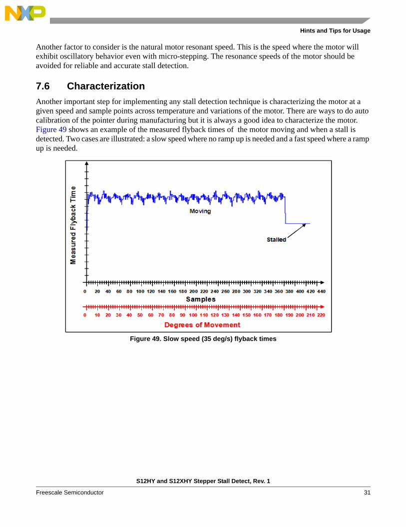
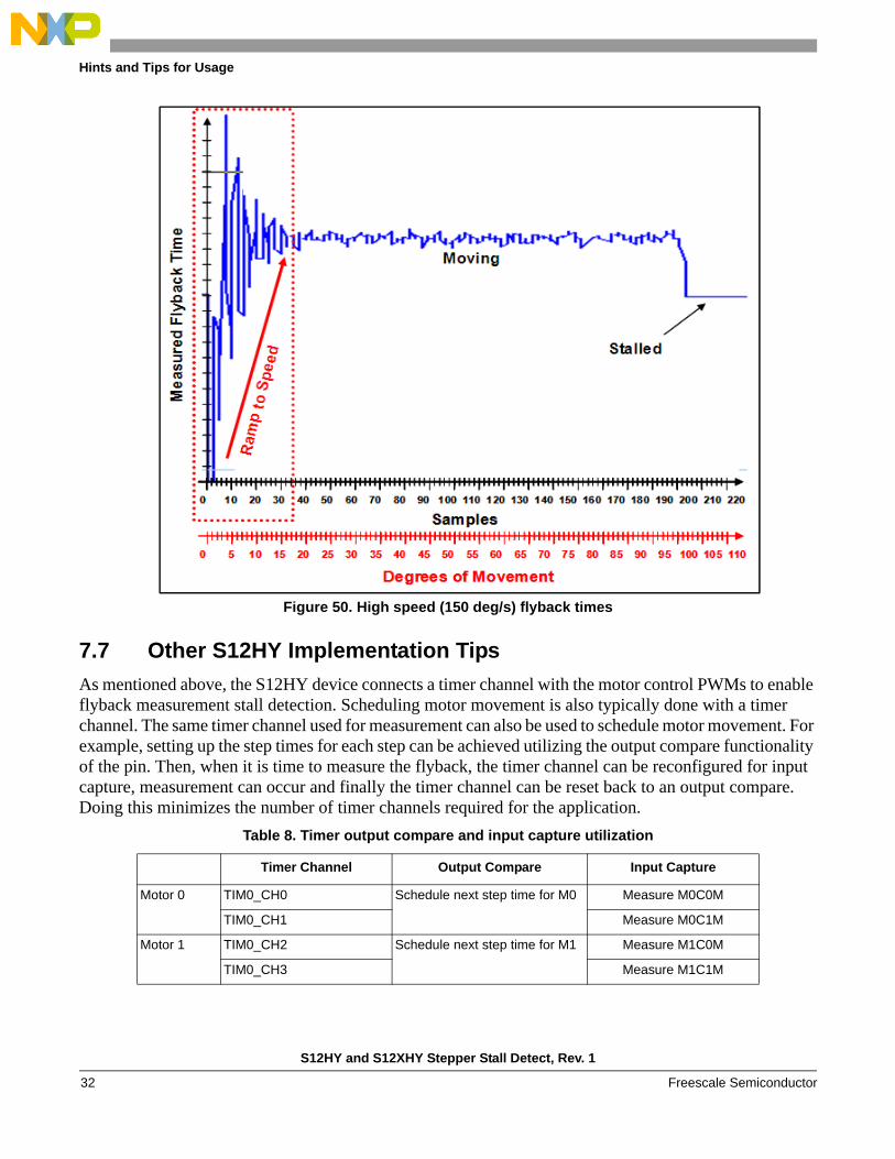
Another important step for implementing any stall detection technique is characterizing the motor at a given speed and sample points across temperature and variations of the motor. There are ways to do auto calibration of the pointer during manufacturing but it is always a good idea to characterize the motor. Figure 49 shows an example of the measured flyback times of the motor moving and when a stall is detected. Two cases are illustrated: a slow speed where no ramp up is needed and a fast speed where a ramp up is needed.
Figure 49. Slow speed (35 deg/s) flyback times
S12HY and S12XHY Stepper Stall Detect, Rev. 1
Freescale Semiconductor 31
Hints and Tips for Usage
Figure 50. High speed (150 deg/s) flyback times
7.7 Other S12HY Implementation Tips
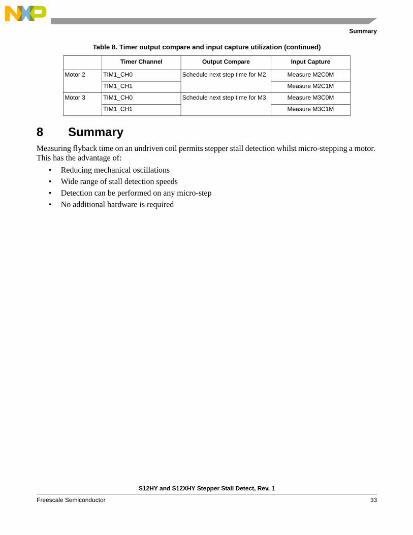
As mentioned above, the S12HY device connects a timer channel with the motor control PWMs to enable flyback measurement stall detection. Scheduling motor movement is also typically done with a timer channel. The same timer channel used for measurement can also be used to schedule motor movement. For example, setting up the step times for each step can be achieved utilizing the output compare functionality of the pin. Then, when it is time to measure the flyback, the timer channel can be reconfigured for input capture, measurement can occur and finally the timer channel can be reset back to an output compare. Doing this minimizes the number of timer channels required for the application.
Table 8. Timer output compare and input capture utilization
Timer Channel Output Compare Input Capture
Motor 0
TIM0_CH0 Schedule next step time for M0
Measure M0C0M
TIM0_CH1 Measure M0C1M
Motor 1
TIM0_CH2 Schedule next step time for M1
Measure M1C0M
TIM0_CH3 Measure M1C1M
S12HY and S12XHY Stepper Stall Detect, Rev. 1
Freescale Semiconductor32
Summary
8 SummaryMeasuring flyback time on an undriven coil permits stepper stall detection whilst micro-stepping a motor. This has the advantage of:
• Reducing mechanical oscillations
• Wide range of stall detection speeds
• Detection can be performed on any micro-step
• No additional hardware is required
Motor 2
TIM1_CH0 Schedule next step time for M2
Measure M2C0M
TIM1_CH1 Measure M2C1M
Motor 3
TIM1_CH0 Schedule next step time for M3
Measure M3C0M
TIM1_CH1 Measure M3C1M
Table 8. Timer output compare and input capture utilization (continued)
Timer Channel Output Compare Input Capture
S12HY and S12XHY Stepper Stall Detect, Rev. 1
Freescale Semiconductor 33
Document Number: AN4024Rev. 111/2010
How to Reach Us:
Home Page:www.freescale.com
Web Support:http://www.freescale.com/support
USA/Europe or Locations Not Listed:Freescale Semiconductor, Inc.Technical Information Center, EL5162100 East Elliot RoadTempe, Arizona 85284+1-800-521-6274 or +1-480-768-2130www.freescale.com/support
Europe, Middle East, and Africa:Freescale Halbleiter Deutschland GmbHTechnical Information CenterSchatzbogen 781829 Muenchen, Germany+44 1296 380 456 (English)+46 8 52200080 (English)+49 89 92103 559 (German)+33 1 69 35 48 48 (French)www.freescale.com/support
Japan:Freescale Semiconductor Japan Ltd.HeadquartersARCO Tower 15F1-8-1, Shimo-Meguro, Meguro-ku,Tokyo 153-0064Japan0120 191014 or +81 3 5437 [email protected]
Asia/Pacific:Freescale Semiconductor China Ltd.Exchange Building 23FNo. 118 Jianguo RoadChaoyang DistrictBeijing 100022 China +86 10 5879 [email protected]
For Literature Requests Only:Freescale Semiconductor Literature Distribution Center1-800-441-2447 or 303-675-2140Fax: [email protected]
Information in this document is provided solely to enable system and software implementers to use Freescale Semiconductor products. There are no express or implied copyright licenses granted hereunder to design or fabricate any integrated circuits or integrated circuits based on the information in this document.
Freescale Semiconductor reserves the right to make changes without further notice to any products herein. Freescale Semiconductor makes no warranty, representation or guarantee regarding the suitability of its products for any particular purpose, nor does Freescale Semiconductor assume any liability arising out of the application or use of any product or circuit, and specifically disclaims any and all liability, including without limitation consequential or incidental damages. “Typical” parameters that may be provided in Freescale Semiconductor data sheets and/or specifications can and do vary in different applications and actual performance may vary over time. All operating parameters, including “Typicals”, must be validated for each customer application by customer’s technical experts. Freescale Semiconductor does not convey any license under its patent rights nor the rights of others. Freescale Semiconductor products are not designed, intended, or authorized for use as components in systems intended for surgical implant into the body, or other applications intended to support or sustain life, or for any other application in which the failure of the Freescale Semiconductor product could create a situation where personal injury or death may occur. Should Buyer purchase or use Freescale Semiconductor products for any such unintended or unauthorized application, Buyer shall indemnify and hold Freescale Semiconductor and its officers, employees, subsidiaries, affiliates, and distributors harmless against all claims, costs, damages, and expenses, and reasonable attorney fees arising out of, directly or indirectly, any claim of personal injury or death associated with such unintended or unauthorized use, even if such claim alleges that Freescale Semiconductor was negligent regarding the design or manufacture of the part.
RoHS-compliant and/or Pb-free versions of Freescale products have the functionality and electrical characteristics as their non-RoHS-compliant and/or non-Pb-free counterparts. For further information, see http://www.freescale.com or contact your Freescale sales representative.
For information on Freescale’s Environmental Products program, go to http://www.freescale.com/epp.
Freescale™ and the Freescale logo are trademarks of Freescale Semiconductor, Inc. All other product or service names are the property of their respective owners.© Freescale Semiconductor, Inc. 2010. All rights reserved.


![Untitled Document [cache.freescale.com]cache.freescale.com/files/microcontrollers/doc/app_note/...Order this document by AN1058/D AN1058 Reducing A/D Errors in Microcontroller Applications](https://img.pdfslide.us/doc/110x75/5aacff027f8b9ac55c8db80a/untitled-document-cache-cache-this-document-by-an1058d-an1058-reducing-ad.jpg)