Embed Size (px)
Citation preview
DESCRIPTION
Catalog #
Project
Comments
Prepared by
Type
Date
SPECIFICATION FEATURES
Eaton18001 E. Colfax AvenueDenver, CO 80011P: 303-393-1522 www.eaton.com/lighting
Specifications and dimensions subject to change without notice.See additional information on the following pages.
TD519033EN08/20/2018
1 of 5
Light Distribution Light Engine Lumen Package Down CCT & Min CRI Celing Type Length Circuiting
S124DR = Define 4Direct RecessedS124RDR = Define 4 Regressed Direct Recessed
-S = Standard-H = High Performance
350D = 350 Lms/ft575D = 575 Lms/ft795D = 795 Lms/ft1020D = 1020 Lms/ft1195D = 1195 Lms/ft____D = Custom Lm/Ft
830 = 3000K, 80CRI835 = 3500K, 80CRI840 = 4000K, 80CRI927 = 2700K, 90CRI 930 = 3000K, 90CRI935 = 3500K, 90CRI940 = 4000K, 90CRI
-ETG = 15/16” T-Grid-FTG = 9/16” T-Grid-STG = 9/16” Slot T-Grid-FTT = 9/16” Tegular T-Grid-ITG = 9/16” Interlude T-Grid-ETT = 15/16” Tegular T-Grid-GYP = Gypsum board-FSR = “Flangeless” Gypsum Board-FES = “Finished” Extruded Side
2F0 = 2’ Individual4F0 = 4’ Individual8F0 = 8’ Individual12F0 = 12’ Individual__F0 = 4’ Incremental Run (e.g. 40F0 = 40’ 0”)__F_ = 1” Incremental Run (e.g. 21F3 = 21’ 3”)
-1 = Single Circuit-S = Secondary Circuit
RDR regress of 1” will add an additional 1” to fixture depth.
Please refer to performance table to determine based on efficacy requirements. Price adder applies for “H” configuration.
3500K/80CRI/DR housing/F Lens. Please refer to scaling data for other variables. For custom lumen output, please refer to additional information on page 2.
Additional lead-time may apply for 927, 930, 935 and 940 configurations.
Please refer to ceiling interface diagrams for ad-ditional detail and dimensions.
Secondary circuit similar to A/B switching. Price adder applies for “S” configuration.
Neo-Ray
Grey bar denotes not available with Define Core10-Day Quick ship options
ORDERING INFORMATION
Sample Number: S124DR-S795D840-ETG4F0-1B1-UDD-F-W-SWPD1
Emergency Voltage Integral LED Driver Shielding Down Options Color Integrated Sensor
E = Emergency circuitB1 = Surelite 7W UNV integral batteryB2 = Surelite 14W UNV integral batteryT = Iota UL924 ETR Emergency Bypass Relay
-U = UNV 120-277V-1 = 120V-2 = 277V-3 = 347V-4 = 48VDC
DD= 0-10 Volt Dimming, 1%5L = DALI Dimming, 5%-100%L5 = Lutron 5-Series LDE5 w/ecosysLH = Lutron HiLume LDE1 w/ecosysLU = Lutron HiLume L3D w/3WLV1 = DLVP
-F = Satin Flush Diffuser-A = Asym Flush Optic-D = Satin Drop Diffuser
-CP = Chicago Plenum-R = GLR Fuse (Fast)-F = GLF Fuse (Slow)
-W = Matte White-S = Silver-B = Black-C = Custom Color
-SWPD1 = WaveLinx Integral-SWTPD1 = WaveLinx Tilemount-LWIPD1 = LumaWatt Pro Integral-LWTPD1 = LumaWatt Pro Tilemount-SVPD1 = Standalone Sensor-SVTPD1 = Standalone Sensor Tilemount
Internal battery standard for fixtures ≥ 4ft and lumen output ≤1200Lms/ft. Fixture Non-IC-Rated for internal battery and lumen output ≥1025 Lms/ft. External battery standard with chicago plenum.
48V for use with LV1 driver. 347V only availabe with DD and 5L drivers.
DD driver is standard. All lensing options are snap-in lenses
Contact factory for custom color
Please refer to page 5 for additional detail required to specify integrated or tile-mount sensors. Integral option not available with regressed, drop or asymmetric configurations. Tilemount configuration recommended for these applications.
quick disconnect wire-harness for ease of installation and maintence over the life of the luminaire.
Light Engine Offered with two next generation Neo-Ray light engines delivering industry leading efficacy and long-life.
LED’s are available in 2700K, 3000K, 3500K or 4000K. CRI options of either ≥80CRI or ≥90CRI are available. Lumen output will be affected - please refer to the lumen adjustment factor table.
LED DriversLED system coupled with electrical driver to deliver optimal performance.
Traditional electronic drivers are available for 120-277V and 347V applications. Eaton’s DLVP Low voltage drivers are available for 48VDC applications.
Controls and Integrated SensorsEquipped standard with a 0-10V continuous dimming driver compatible with most standard dimming devices. Additional control types are available (DALI, Lutron, DLVP) at an additional cost. WaveLinx and LumaWatt Pro wireless sensors as well as stand-alone sensors available.
WarrantyFive year warranty.
ConstructionPrecision cut housing trim extruded from 6063 aluminum with aluminum frame. Extruded end-caps ensure a precise and uniform ceiling interface.Nominal 2’ -12’ illuminated sections used in run configuration and/or individual fixtures.
FinishFixture housing trims are high reflective white (unless otherwise specified) using electrostatically applied polyester powder coat paint.
LED ModuleModular LED tray assembly comprising reflector, light engine, led driver and
DEFINE 4 LED
Recessed Direct
The Define series by Neo-Ray characterizes the ultimate in minimalist simplicity by providing clean, uniform lines of illumination in virtually any architectural environment. Powered Eaton’s most advanced linear LED technology, the Define series delivers out-standing efficacy in a variety of profile widths. 1.5”, 2”, 3”, 4” and 5” luminaire widths are all specifiable to the nearest inch in length and can be fitted with standard flush, asym-metric flush, regressed and drop lensing. In-ceiling and in-wall corners as well as wall to ceiling transitions can all be ordered as standard components and blend seamlessly into the most complex architectural spaces. Custom transitions are also available. Robust construction and adaptable, modular components make installation simple and ensure laser straight runs.
cULus – 1598Damp Location Listed
LM79/LM80 CompliantROHS Compliant
Lumawatt Pro WirelessWaveLinx Wireless
Made in USA
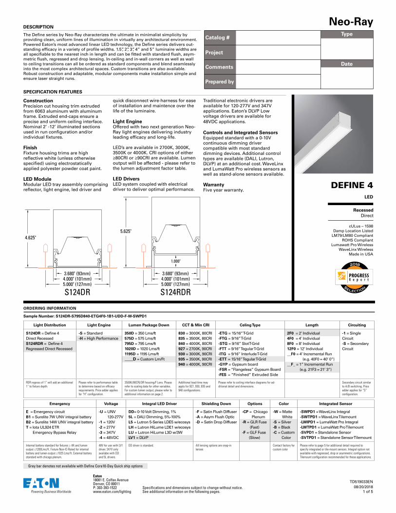
S124DR5.000" (127mm)
4.625"
4.000" (101mm)3.680" (93mm)
5.000" (127mm)
5.625"
4.000" (101mm)3.680" (93mm)
S124RDR
1.000"
PROGRESSR e p o r t
Selection
Eaton18001 E. Colfax AvenueDenver, CO 80011P: 303-393-1522 www.eaton.com/lighting
Specifications and dimensions subject to change without notice.See additional information on the following pages.
TD519033EN08/20/2018
2 of 5
Neo-Ray - Define - RecessedNeo-Ray - Define - RecessedSPECIFICATION FEATURES CONTINUED
high reflectivity (standard) and ultra-high reflectivity (used with High Performance light engine).
Lumen Maintenance90% (L90) of initial light output at 100,000+ hrs. 70% (L70) of initial light output at 400,000+ hrs, reported L70 >60,000 hrs. Derived from TM-21 standard @25°C ambient and typical operating conditions. Consult factory for additional data.
Custom Lumen OutputYou can select a custom lumen output for your application in Lumens per foot (e.g. -725D for 725 Lms/ft down). Desired output must with within the total light output range. Please contact factory for custom lumen output when not selecting the standard 0-10V ‘DD’ Driver.
If your requirement is expressed in power consumption (W/ft) rather than light output, you can use the power to lumen output curves to convert power consumption to light output for specification.
Efficacy for custom lumen outputs can be estimated using lumen output curves or with the use of our online custom lumen output tool.
ElectricalDimming provided as standard - dimming wires are capped with wire-nuts for non-dimming applications.
Optional battery backup options provided. Default battery location is internal to fixture to reduce field wiring with pre-wired external test switch. Default emergency section is 4ft in length and located at the beginning of the fixture unless designated elsewhere using our linear product configurator tool. To estimate lumen output from the emergency section, multiply battery wattage x minimum fixture efficacy from performance table below (e.g. 14W x 116 lm/W = 1624 lms).
Our ETS-DR option will provide switching for both power and dimming wires for applications requiring a UL924 transfer device.
Integrated SensorsPlease reference page 5 for details.
Weight2.65 lbs per foot.
ApprovalscULus - 1598Meets NYC requirements.Meets CCEC requirements (Chicago Plenum).Suitable for damp locations.IC Rated (except where noted)
MountingRecessed.
LengthsAvailable in any length (23” min) with a resolution of 1 inch. Max section length of 12ft (8ft max option available). Additional fixture lengths are available - please consult factory.
All lengths are nominal. Actual sizes are one inch shorter than nominal to allow easy in-grid installation. For Gypsum or Flangeless installations add 1 inch to overall fixture length. Refer to ceiling type section of specification sheet and submittal drawings for actual sizes.
Corners and Transition PiecesCorners and other transition pieces are fully luminous and contructed using precision mitered frame and lens components. The frame is welded to ensure a precise and robust assembly. Standard 90° horizontal and vertical corners as well as custom corners are available. Please consult online linear configutor or the factory for precise corner locations and for ordering. Alternative transition pieces such as T’s, Y’s, X’s, etc. are also available.
Snap-In Lensing OptionsSatin Flush - Flush, high diffusion glare-free lensSatin Proud - 1” Proud, high diffusion glare-free lensAsymmetric - Flush, low-glare Asymmetric lens
Flush options ship with our patent-pending under-lens solution, while the proud lens ships with an injection molded end cap to eliminate light leak.
ReflectorsPrecision formed cold-rolled steel reflectors with
PERFORMANCE PER LINEAR FOOT AT 3500K/80CRI
Nominal Lumen Output
StandardLight Engine
High Performance Light Engine
350 lms/ft 2.9 W/ft 121 lm/W 2.8 W/ft 127 lm/W
575 lms/ft 4.7 W/ft 122 lm/W 4.3 W/ft 131 lm/W
795 lms/ft 6.6 W/ft 121 lm/W 5.9 W/ft 134 lm/W
1020 lms/ft 8.7 W/ft 117 lm/W 7.9 W/ft 130 lm/W
1195 lms/ft 10.3 W/ft 116 lm/W 9.4 W/ft 126 lm/W
LUMEN ADJUSTMENT FACTORS
PHOTOMETRIC OVERVIEW AND PERFORMANCE DATA
Example 1 - Adjusted Lumen Output Nominal Lumen Output selected = 1025 lms/ft (based on standard of 3500K/80CRI)Lumen Adjustment Factor = 0.801 (2700K/90CRI desired)
Adjusted Lumen Output = Nominal Lumen Output x Lumen Adjustment FactorAdjusted Lumen Output = 1025 lms/ft x 0.801 = 821 lms/ft
Example 2 - Custom Lumen Output based on Required Lumens Per FootTotal light output (4ft) requirement of 2800 lms, desired CCT and CRI of 4000K/80CRI
Total required lumens per foot @ 4000K= 2800 lms / 4 ft = 700 lms/ftLumen Adjustment Factor = 1.018 (Requirement based on 4000K / 80CRI)
Total required lumens per foot @ 3500K / 80CRI = 700 lms/ft ÷ 1.018 = 688 lms/ft
Estimated efficacy = 121 lm/W (find nearest value using table above)Estimated power consumption = 688 lms/ft ÷ 121 lm/W = 5.69 W/ft
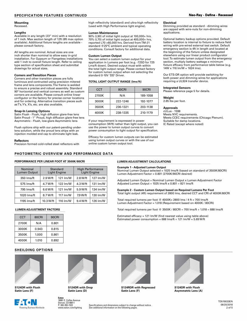
S124DR with Flush Satin Lens (F)
S124DR with Drop Satin Lens (D)
S124RDR with Regressed Satin Lens (F)
S124DR with Flush Asymmetric Lens (A)
LUMEN ADJUSTMENT CALCULATIONS
TOTAL LIGHT OUTPUT RANGE (lms/ft)
CCT 80CRI 90CRI
2700K N/A 189-1058
3000K 222-1246 192-1077
3500K 236-1321 203-1138
4000K 238-1335 210-1179
SHEILDING OPTIONS
CCT 80CRI 90CRI
2700K N/A 0.801
3000K 0.943 0.815
3500K 1.000 0.861
4000K 1.010 0.892
Eaton18001 E. Colfax AvenueDenver, CO 80011P: 303-393-1522 www.eaton.com/lighting
Specifications and dimensions subject to change without notice.See additional information on the following pages.
TD519033EN08/20/2018
3 of 5
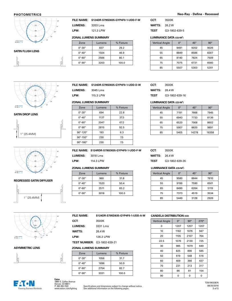
Neo-Ray - Define - RecessedPHOTOMETRICS
FILE NAME: S124DR-S795D835-GYP4F0-1-UDD-F-W CCT: 3500K
LUMENS: 3203 Lms WATTS: 26.2 W
LPW: 121.3 LPW TEST G3-1802-639-5
FILE NAME: S124DR-S795D835-GYP4F0-1-UDD-A-W
CCT: 3500K
LUMENS: 3331 Lms
WATTS: 26.4 W
LPW: 126.2 LPW
TEST NUMBER: G3-1802-639-21
SATIN FLUSH LENS
SATIN DROP LENS
ASYMMETRIC LENS
REGRESSED SATIN DIFFUSER
LUMINANCE DATA (CD/M2)
Vertical Angle 0º 45º 90º
45 9491 9202 9026
55 8849 8586 8307
65 8140 7824 7509
75 7075 6731 6560
85 5507 5303 5201
ZONAL LUMENS SUMMARY
Zone Lumens % Fixture
0º-30º 837 29.2
0º-40º 1504 46.9
0º-60º 2566 80.1
0º-90º 3203 100.0
LUMINANCE DATA (CD/M2)
Vertical Angle 0º 45º 90º
45 7191 7668 7945
55 6943 7733 8136
65 6520 7908 8602
75 5907 8620 9891
85 5405 14278 18358
ZONAL LUMENS SUMMARY
Zone Lumens % Fixture
0º-30º 694 22.8
0º-40º 1137 37.3
0º-60º 2047 67.2
0º-90º 2815 92.5
90º-120º 193 6.3
90º-150º 230 7.5
90º-180º 230 7.5
ZONAL LUMENS SUMMARY
Zone Lumens % Fixture
0º-30º 960 31.8
0º-40º 1520 50.4
0º-60º 2511 83.2
0º-90º 3018 100.0
LUMINANCE DATA (CD/M2)
Vertical Angle 0º 45º 90º
45 9580 8644 7810
55 9199 7590 6501
65 8490 6264 5119
75 7373 4519 3534
85 5449 3128 2926
ZONAL LUMENS SUMMARY
Zone Lumens % Fixture
0º-30º 1056 31.7
0º-40º 1696 50.9
0º-60º 2754 82.7
0º-90º 3331 100.0
CANDELA DISTRIBUTION (CD)
Vertical Angle 0º 90° 270°
0 1207 1207 1207
10 1182 1676 947
20 1105 2107 764
22.5 1076 2130 725
30 985 1679 649
40 825 890 585
50 619 548 516
60 409 366 437
70 231 213 317
80 86 81 154
90 0 0 0
FILE NAME: S124DR-S795D835-GYP4F0-1-UDD-D-W CCT: 3500K
LUMENS: 3045 Lms WATTS: 26.4 W
LPW: 115.3 LPW TEST G3-1802-639-16
FILE NAME: S124RDR-S795D835-GYP4F0-1-UDD-F-W CCT: 3500K
LUMENS: 3018 Lms WATTS: 26.4 W
LPW: 114.3 LPW TEST G3-1802-639-26
0°
30°
60°
90°
15°
45°
75°313
626
939
1252 0 deg90 deg
0°
30°
60°
90°
15°
45°
75°224
449
673
897 0 deg90 deg
0°
30°
60°
90°
15°
45°
75°328
655
983
1310 0 deg90 deg
0°
30°
60°
90°
15°
45°
75°
0 deg90 deg
2130
1598
1065
533
1” [25.4MM]
1” [25.4MM]
Eaton18001 E. Colfax AvenueDenver, CO 80011P: 303-393-1522 www.eaton.com/lighting
Specifications and dimensions subject to change without notice.See additional information on the following pages.
TD519033EN08/20/2018
4 of 5
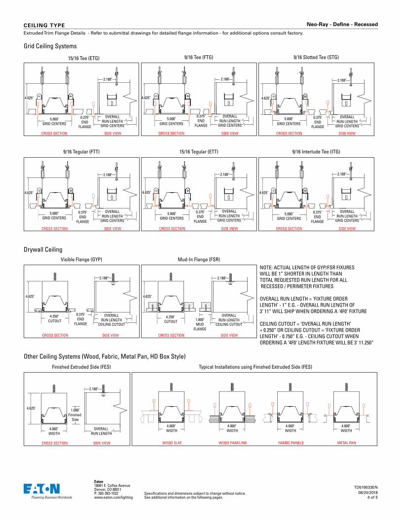
Neo-Ray - Define - RecessedCEILING TYPE
15/16 Tegular (ETT)
Mud-In Flange (FSR)
9/16 Tee (FTG)15/16 Tee (ETG)
Finished Extruded Side (FES)
9/16 Tegular (FTT)
Visible Flange (GYP)
5.000"GRID CENTERS GRID CENTERS
CROSS SECTION SIDE VIEW
OVERALLRUN LENGTH
2.188"
0.375"END
FLANGE
4.625"
9/16 Interlude Tee (ITG)
9/16 Slotted Tee (STG)
Grid Ceiling Systems
Drywall Ceiling
Other Ceiling Systems (Wood, Fabric, Metal Pan, HD Box Style)
2.188"
4.625"
CROSS SECTION SIDE VIEW
2.188"
4.625"
5.000"GRID CENTERS
CROSS SECTION SIDE VIEW
0.375"END
FLANGE
CROSS SECTION SIDE VIEWCROSS SECTION SIDE VIEWCROSS SECTION SIDE VIEW
2.188"
4.625"
4.250" CUTOUT
CROSS SECTION SIDE VIEW
0.375"END
FLANGE
CROSS SECTION SIDE VIEW
OVERALL RUN LENGTH
4.000" WIDTH
2.188"
4.625"
2.188"
4.625"
4.250" CUTOUT
CROSS SECTION SIDE VIEW
1.000"MUD
FLANGE
Typical Installations using Finished Extruded Side (FES)
1.000"Finished
Side
WOOD PANELING FABRIC PANELS METAL PANWOOD SLAT
4.000" WIDTH
4.000" WIDTH
4.000" WIDTH
4.000" WIDTH
NOTE: ACTUAL LENGTH OF GYP/FSR FIXURES WILL BE 1” SHORTER IN LENGTH THAN TOTAL REQUESTED RUN LENGTH FOR ALL RECESSED / PERIMETER FIXTURES
OVERALL RUN LENGTH = ‘FIXTURE ORDER LENGTH’ - 1” E.G. - OVERALL RUN LENGTH OF 3’ 11” WILL SHIP WHEN ORDERING A ‘4F0’ FIXTURE
CEILING CUTOUT = ‘OVERALL RUN LENGTH’ + 0.250“ OR CEILING CUTOUT = ‘FIXTURE ORDER LENGTH’ - 0.750” E.G. - CEILING CUTOUT WHEN ORDERING A ‘4F0’ LENGTH FIXTURE WILL BE 3’ 11.250”
GRID CENTERS
OVERALLRUN LENGTH 5.000"
GRID CENTERS
0.375"END
FLANGE GRID CENTERS
OVERALLRUN LENGTH
5.000"GRID CENTERS
GRID CENTERS
OVERALLRUN LENGTH
CEILING CUTOUT
OVERALLRUN LENGTH
CEILING CUTOUT
OVERALLRUN LENGTH
2.188"
0.375"END
FLANGE
4.625"
5.000"GRID CENTERS GRID CENTERS
OVERALLRUN LENGTH
2.188"
0.375"END
FLANGE
4.625"
5.000"GRID CENTERS GRID CENTERS
OVERALLRUN LENGTH
2.188"
0.375"END
FLANGE
4.625"
Extruded Trim Flange Details - Refer to submittal drawings for detailed flange information - for additional options consult factory.
Eaton18001 E. Colfax AvenueDenver, CO 80011P: 303-393-1522 www.eaton.com/lighting
Specifications and dimensions subject to change without notice.See additional information on the following pages.
TD519033EN08/20/2018
5 of 5
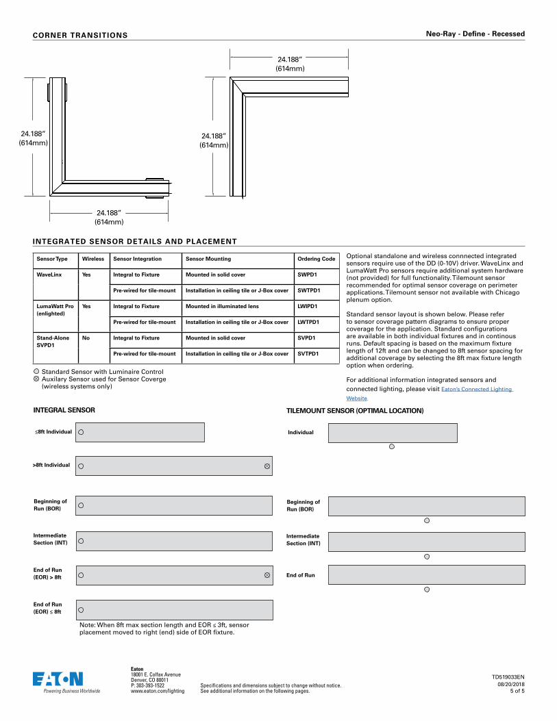
Neo-Ray - Define - RecessedCORNER TRANSITIONS
24.188”(614mm)
24.188”(614mm)
24.188”(614mm)
24.188”(614mm)
INTEGRATED SENSOR DETAILS AND PLACEMENT
Sensor Type Wireless Sensor Integration Sensor Mounting Ordering Code
WaveLinx Yes Integral to Fixture Mounted in solid cover SWPD1
Pre-wired for tile-mount Installation in ceiling tile or J-Box cover SWTPD1
LumaWatt Pro (enlighted)
Yes Integral to Fixture Mounted in illuminated lens LWIPD1
Pre-wired for tile-mount Installation in ceiling tile or J-Box cover LWTPD1
Stand-Alone SVPD1
No Integral to Fixture Mounted in solid cover SVPD1
Pre-wired for tile-mount Installation in ceiling tile or J-Box cover SVTPD1
Optional standalone and wireless connnected integrated sensors require use of the DD (0-10V) driver. WaveLinx and LumaWatt Pro sensors require additional system hardware (not provided) for full functionality. Tilemount sensor recommended for optimal sensor coverage on perimeter applications. Tilemount sensor not available with Chicago plenum option.
Standard sensor layout is shown below. Please refer to sensor coverage pattern diagrams to ensure proper coverage for the application. Standard configurations are available in both individual fixtures and in continous runs. Default spacing is based on the maximum fixture length of 12ft and can be changed to 8ft sensor spacing for additional coverage by selecting the 8ft max fixture length option when ordering.
For additional information integrated sensors and connected lighting, please visit Eaton’s Connected Lighting
Website.
≤8ft Individual
>8ft Individual
INTEGRAL SENSOR
Beginning of Run (BOR)
Intermediate Section (INT)
End of Run (EOR) > 8ft
End of Run (EOR) ≤ 8ft
Individual
TILEMOUNT SENSOR (OPTIMAL LOCATION)
Beginning of Run (BOR)
Intermediate Section (INT)
End of Run
Note: When 8ft max section length and EOR ≤ 3ft, sensor placement moved to right (end) side of EOR fixture.
Standard Sensor with Luminaire ControlAuxilary Sensor used for Sensor Coverge (wireless systems only)