Embed Size (px)
Citation preview
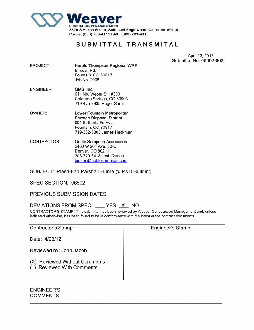
3679 S Huron Street, Suite 404 Englewood, Colorado 80110
Phone: (303) 789-4111 FAX: (303) 789-4310
S U B M I T T A L T R A N S M I T A L
April 23, 2012
Submittal No: 06602-002 PROJECT: Harold Thompson Regional WRF
Birdsall Rd. Fountain, CO 80817 Job No. 2908
ENGINEER: GMS, Inc. 611 No. Weber St., #300 Colorado Springs, CO 80903 719-475-2935 Roger Sams
OWNER: Lower Fountain Metropolitan Sewage Disposal District 901 S. Santa Fe Ave. Fountain, CO 80817 719-382-5303 James Heckman
CONTRACTOR: Goble Sampson Associates 2460 W 26
th Ave, 30-C
Denver, CO 80211 303-770-6418 Josh Queen [email protected]
SUBJECT: Plasti-Fab Parshall Flume @ P&D Building
SPEC SECTION: 06602 PREVIOUS SUBMISSION DATES: DEVIATIONS FROM SPEC: YES X NO CONTRACTOR’S STAMP: This submittal has been reviewed by Weaver Construction Management and, unless
indicated otherwise, has been found to be in conformance with the intent of the contract documents.
Contractor’s Stamp: Engineer’s Stamp: Date: 4/23/12 Reviewed by: John Jacob (X) Reviewed Without Comments ( ) Reviewed With Comments ENGINEER’S COMMENTS:_________________________________________________________________________________________________________________________________

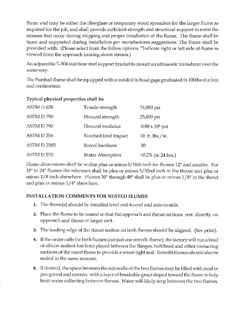
Parshall Flumes
Palmer-Bowlus Flumes
H-Flumes
Mag Meter Manhole
Packaged Metering Manhole
Trapezoidal Flumes
Flow Measurement Products
Over 40 years of excellence in engineering and fabricating composite flow measurement products. Plasti-Fab flow measurement products have a 25 year corrosion warranty.
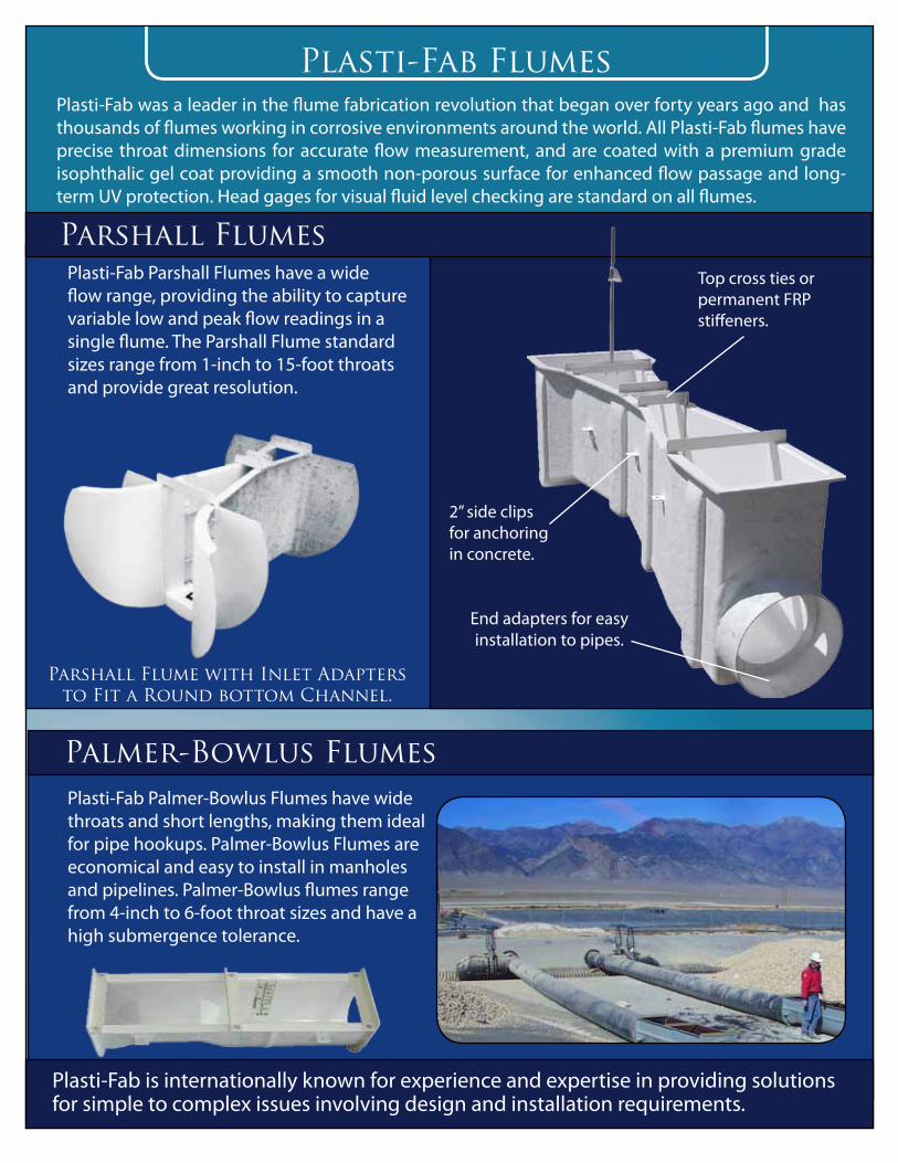
Plasti-Fab FlumesPlasti-Fab was a leader in the flume fabrication revolution that began over forty years ago and has thousands of flumes working in corrosive environments around the world. All Plasti-Fab flumes have precise throat dimensions for accurate flow measurement, and are coated with a premium grade isophthalic gel coat providing a smooth non-porous surface for enhanced flow passage and long-term UV protection. Head gages for visual fluid level checking are standard on all flumes.
Palmer-Bowlus Flumes
Plasti-Fab Parshall Flumes have a wide flow range, providing the ability to capture variable low and peak flow readings in a single flume. The Parshall Flume standard sizes range from 1-inch to 15-foot throats and provide great resolution.
Plasti-Fab Palmer-Bowlus Flumes have wide throats and short lengths, making them ideal for pipe hookups. Palmer-Bowlus Flumes are economical and easy to install in manholes and pipelines. Palmer-Bowlus flumes range from 4-inch to 6-foot throat sizes and have a high submergence tolerance.
Parshall Flume with Inlet Adapters to Fit a Round bottom Channel.
Parshall FlumesTop cross ties or permanent FRP stiffeners.
2” side clips for anchoring in concrete.
End adapters for easy installation to pipes.
Plasti-Fab is internationally known for experience and expertise in providing solutions for simple to complex issues involving design and installation requirements.

Plasti-Fab Flumes
H-FlumesPlasti-Fab H-Flumes can accommodate the widest range of flow and have a high tolerance for velocity. The H-Flumes have a usable range of more than 100:1, making them ideal for applications such as storm water measurement. The H-Flumes standard sizes range from 0.4 to 4.0 feet.
Trapezoidal FlumesPlasti-Fab Trapezoidal Flumes are low profile and provide excellent low-flow resolution. Trapezoidal Flumes offer the ability to provide repeatable accurate measurements in flows down to 1 GPM to meet stringent requirements. The Trapezoidal Flumes are available in eight standard sizes. Plasti-Fab Trapezoidal Flumes are available in a variety
of configurations and have many accessory options.
Plasti-Fab is a world class manufacturer of composites with over 40 years of experience designing, engineering and building products for fluid management and control. Plasti-Fab products are fabricated from highly corrosion resistant composite fiberglass reinforced plastic (FRP). Recognized around the world as an experienced innovator and provider of quality composite solutions, Plasti-Fab has a wealth of experience and expertise in flow measurement products.
Visit us online at: www.plasti-fab.com
The Plasti-fab Legacy
Flume Customization Some standard options for flumes include:• Inlet and Outlet Adapters• Wingwalls and Bulkheads• Pipe Stubs or Caulking Collars• Slip Flanges• Neoprene Boots with S/S Bands• End Walls for Approach
• Bubble Pipes• Sample Pipes• Sonic Mounting Brackets• Stilling Wells• pH Probe Lift-Out Brackets• Capacitance Probe Side Cavities• Pressure Transducer Cavities• Threaded Taps
• Two Vial Bubble Levels• Temperature Probes with Lift-Out Brackets• Nested, Insert, and Staged Flumes• Magic Bottoms• Access Boxes• Tranquilizing Racks

Packaged Metering ManholesThe Plasti-Fab Packaged Metering Manhole, an industry first, is an integral solution to underground flow measurement needs. The PMM reduces installation errors and installation time. PMMs are available with any size flume by locating the barrel over the measuring point. The PMM offers contractors, engineers, and municipalities, peace of mind knowing that the professionally installed integral flume provides maximum accuracy of flow measurement in a long lasting, water-tight and sanitary operating environment.
Plasti-Fab Packaged Metering Manholes (PMMs) are watertight one-piece construction with an integral bottom. They weigh only a fraction of comparable concrete or steel manholes and are extremely resistant to chemicals, saltwater, corrosive soils, ground water and electrolysis. Manhole bottoms are a dual-layer construction to prevent oil canning and provide a flat installation surface. Packaged Metering Manhole tops may be designed for steel covers to meet H-20 highway loading, or with hinged FRP lids and lockable hasps, or with aluminum hatches for water/gas tight applications, or completely customized. The PMM interior is premium
isophthalic white gel coat that provides a smooth non-porous surface to resist bacteria for a cleaner workspace and to allow for maximum illumination. All hardware is heavy-duty stainless steel. Anchor tabs are mechanically fastened to the barrel to ensure a secure installation. Pipe stubs are built to match the ID and OD of the mating pipe. Invert elevations can be adjusted to meet the elevation of the pipe in the field. PMMs may be completely customized with a full range of accessories.Standard options include FRP Ladders, Ladder Lifts, Head Deflectors, Threaded Taps, Shelves, FRP Grating, Pulleys, Vents and Fans.
Flow Measurement Manholes
Full Range ofIntegrated
FlumesAvailable
Mag Metering ManholesThe Plasti-Fab Mag Meter Manhole (MMM) is an integrated solution for closed pipe flow measurement needs. The Mag meter is installed within the manhole barrel, providing a clean, dry, leak proof environment. The Plasti-Fab MMM is engineered for high pressure water lines and includes bolting flanges for attachment of the mag meter. Plasti-Fab will factory install customer furnished mag meters.
Brochure FM-2.01.10 - Copyright© - 2009 Plasti-Fab Inc. - Plasti-Fab® is a trademark of Plasti-Fab Inc.
Contact Your Local Plasti-Fab Representativehttp://www.plasti-fab.com./fiberglass-manufacturing-
representatives
PLASTI-FAB Inc.PO Box 100Tualatin, Oregon 97062-0100(503) [email protected] www.plasti-fab.com
Facilities located in Lakeland, Florida and Tualatin, Oregon
Manhole Centered over Measuring Point
Mag Meters and other devices may be professionally
installed at the factory
Page 1 of 1
INSTALLATION INSTRUCTIONS
NESTED PARSHALL FLUMES
Flumes shall be installed level end-to-end and side-to-side by using a level on the floor of the inside
flume.
1. Flumes must be cribbed or shored up inside in order to keep the sidewalls plumb and maintain the
dimensional integrity of the flume. The throat is the most critical portion of the flume to protect. For
Nested flumes this may be accomplished by shoring up the inside flume and bracing the larger flume in
one of the following manners.
Carefully placing spacer blocks between the walls of the two flumes, or . . .
Fill the space between the walls with sand. (This can be capped with a 2" - 3" grout layer after
installation is complete.), or . . . .
Fill the space with water. (During installation concrete must be placed in 6" to 10" lifts. See Note 6
below)
2. The top cross ties should be left on the flume until it has been installed. If the flume is set in concrete
the cross ties can be removed if desired. Wood cross ties are not intended for permanent installation.
3. Cross beams are suggested for the leveling of the flume, prevention of floating and limiting shifting of
the flume during the grouting process. These cross beams will span the channel and attach to each of the
side channel walls. Then drill through the top flange of the flume and bolt to these beams. Double nut
or shim to get the flume set level both directions. Other cross bracing may be required to prevent
shifting. It may be desirable to do cross bracing near or at the bottom of the flume.
NOTE: Flumes must remain level both directions.
4. Secure the 2” x 2” angle clips on flume to rebar with No. 8 wire or put rebar through the clips to key
the flume into the concrete. (Concrete does not bond well to fiberglass). The 2” x 2” angle clips are not
made for leveling or to prevent shifting.
5. Plasti-Fab flumes are designed to be free standing, and require no additional external support in order
to maintain their dimensional integrity during operation. However they need to have the bottom
adequately supported to be keep the flume and the floor level. This is especially true for flumes having a
throat width of 12” or more.
6. The flume is commonly grouted into an existing concrete channel. This allows for the crossbeams
(see # 3 above) to be used. Grouting into an existing channel is the preferred method of installation.
Pouring the concrete or grout around the flume to fast can deform the sides/floor of the flume, force it to
shift out of alignment or make it out of level. Great care must be taken if a vibrator is used. It can also
cause distortion. Proper bracing/cribbing is important (see #1 above).
NOTE: When installing a flume we would recommend that concrete or grout be poured in layers of not
more than 6”- 10” at a time and each layer be allowed to take a set before the next is added.
7. A long flared inlet transition should be made from the inlet of a flume upstream to the approach
channel or pipe. This is to smoothly transition or “funnel” the flow from the shape and size of the inlet
channel to the shape and size of the flume.
Flow must be non-turbulent and have a low approach velocity. An outlet transition may also be required to help the
flow return smoothly back into a pipe so the flow doesn’t back up into the flume.
8. Not Used - All flumes with bolt on adapters, caulking collars or transition sections must be sealed
between joints. We suggest applying one or two continuous bead(s) of silicone on all seating surfaces
between flanged joints before bolting together.
Please note for flumes which are being installed by using caulking collars in an existing pipe line; the
length of pipe to cut out should be 1” to 2” longer then the measurement from the inside wall of the inlet
adapter to the inside wall of the outlet adapter. Cut out the pipe. Slip each caulking collar over the
pipe. Bolt and seal the flume between the caulking collars. Align the hole through the wall of the
adapter with the pipe hole. Pack the area in the caulking collar between the outside of the pipe and the
inside of the caulking collar with oakum, grout or some other type of packing. (This does not need to be
leak proof if the flume will be encased in concrete.) Then level and brace the flume as noted above.
9. Not Used - An inlet adapter should have a ramped floor for transitioning flows up to the floor of the
flume. This will help transition solids and help facilitate a nonturbulent flow into the flume. Some of
our adapters have a built in ramp from the floor of the adapter to the floor of the flume. If your inlet
adapter does not have a built in ramp, you will need to grout a ramp from the inlet pipe invert to the
floor of the flume. At times, even an inlet adapter with a built in ramped floor, may be better off having
additional grouting added if the inlet pipe is set more than 2” off the floor of the adapter. This again
will maximize transitioning solids and assist in creating a nonturbulent flow.
10. Not Used - 60” Parshall flumes (or larger) have steel tubes laminated to the floor of the flume.
These tubes may also be used to secure the flume in place and level it. For wide spans extra support may
be required under the flume to keep the floor flat and level.
ADDITIONAL NOTES: The interior flume and nesting hardware has been pre-installed at the factory and
all joints have been sealed. When this flume is level both flumes should be level. If for any reason the
inner flume is removed and must be reinstalled/nested -
Place the flume to be nested so that the flat section of the throat rests evenly on the throat of the larger
unit.
The leading edge of the throat section on both flumes should be aligned. (See print.)
Position and level the inner flume so that it matches the pre-drilled mounting holes. Apply a bead of
silicon or other watertight sealant to the flange, bulkhead and other contacting surfaces of the insert
flume. Bolt into place using 3/8" stainless steel anchor bolts or lag bolts.
If desired, the space between the sidewalls of the two flumes may be filled with sand and covered with a
layer of breakable grout to help prevent collection of water between the flumes.
Installation Comments: The flow coming into the flume must be non-turbulent and have a low
approach velocity. Consult factory if you have steep slope, pumping, tank dumping, vertical drop or are
uncertain as to acceptable slopes and velocities for your installation. Downstream of the flume the flow
must get away from the flume. To this end the channel or pipe must be large enough and have enough
slope or drop to take the flow away from the flume with out creating back water submergence. At times
an outlet transition may also be required to help funnel the flow smoothly back into a pipe. This would
be to help prevent the flow from backing up into the flume.
Parshall: The outlet of the flume is best suited to be higher than the outlet pipe (or channel) to help get
the flow away from the flume. This is especially important when reentering a pipe that is running more
than 75 % full.
The inlet of the flume may be at the same elevation as the inlet pipe or channel, but is commonly set
higher. A ramp should be grouted to this higher elevation at a 4:1 slope to help transition solids through
the flume. At no time should the inlet pipe or channel be set higher than the inlet floor of the flume.
If you support the interior adequately, take your time and keep in mind the above suggestions, you should
have a successful installation.
Please consult your local representative or contact Plasti-Fab, Inc., PO Box 100, Tualatin, Oregon, 97062.
PHONE 503-692-5460 FAX 503-692-1145 E-MAIL [email protected] WEB WWW.PLASTI-FAB.COM
PARSHALL FLUME
RECEIVING AND STORAGE SUGGESTIONS
GENERAL
This covers the full range of flumes manufactured by Plasti-Fab. Therefore, some information may not be applicable to your particular installation. Please reference this information with that in mind. RECEIVING
Check/Count all parts when you receive shipment. All individually shipped parts or assemblies are listed on packing list. Should a shortage exist, notify Plasti-Fab, Inc. immediately. We cannot be responsible for any shortages reported more than 30 days after receipt of shipment. Special care should be taken in accounting for and safely storing all bolts, nuts and small items, which can be misplaced at job sites. Unless your contract with Plasti-Fab, Inc. states otherwise, all equipment is shipped f.o.b. factory. If any equipment has been damaged in transit, the purchaser will be responsible for filing a claim with the transportation company. For assistance in filing any claims and/or replacing equipment, please contact Plasti-Fab, Inc. directly. HANDLING AND STORAGE
All Plasti-Fab flumes and accessories are precision parts that should be handled accordingly. While all parts are of rugged design, it is never the less possible to damage surfaces, etc., through improper storage and handling. To avoid all problems of this nature we recommend the following.
1. If flume(s) are too large to lift by hand, use spreader bar and canvas lifting straps around the flume to avoid scratching or damaging surfaces. Some very large or sectioned flumes have built-in half round lifting eyes for canvas lifting straps.
2. If flume(s) will not be installed immediately store equipment on a level, clean surface to prevent distortion. Flumes should be left on shipping skid and stored in upside down position.
3. Cover all equipment to protect surfaces. 4. DO NOT STACK EQUIPMENT.
Please contact Plasti-Fab if you have any questions.
Please consult your local representative or contact Plasti-Fab, Inc., PO Box 100, Tualatin, Oregon, 97062.
PHONE 503-692-5460 FAX 503-692-1145 E-MAIL [email protected] WEB WWW.PLASTI-FAB.COM
Page 1 of 1
FLUMES: OPERATION AND MAINTENANCE SUGGESTIONS
The purpose of this manual is to provide information to the engineers, contractors, plant operators and
associated personnel involved with installation, operation and maintenance of equipment supplied by
Plasti-Fab, Inc. for this project. Although every care is taken in our factory to insure top quality, we
cannot be responsible for damage caused by negligence during or after shipping. Herein are Plasti-Fab’s
recommendations for handling, storage, installation, and initial operation in standard situations. These
suggestions should be used in conjunction with the approved installation drawings provided by Plasti-
Fab, Inc. If proper care and accuracy are exercised in the field, the flume(s) will operate as designed at
maximum efficiency.
Your Plasti-Fab flume is manufactured of fiberglass reinforced polyester (FRP) which includes a white
pigmented interior layer of pure resin that is highly resistant to weathering, water and sewerage,
detergents and acidic fluids. Under most conditions there should be no maintenance required. In some
instances you may wish to wash the surface of the flume if it has become heavily coated with oil or
various sludge buildups. In this case we suggest the use of water and a strong industrial detergent.
In operation, the flume acts as a restrictive venturi causing the water to dam up on the upstream end of
the flume, thereby increasing flow velocity as it passes through the throat to the downstream channel.
Measurement of the depth of the water in the upstream end of the flume provides a means by which the
rate of flow may be determined from flow charts. Many flumes are equipped with instruments that
monitor water depth and record the rate of flow on a chart. Please see the instrument manufacturer’s
manual for calibration and operating instructions on this equipment.
Proper operation and performance of the flume is based on:
1. Proper selection of the type and size of flume
2. Proper installation.
3. Flow entering the flume at subcritical velocity. High velocity is generally caused by excessive
pipeline or channel slope, pumped flow, or a pressure head.
4. Flow surface being smooth, non-turbulent, in straight filaments.
5. Proper sizing of downstream conduit to take flow away from the flume.
6. Proper location and calibration of the flow instrument.
Since there are no moving parts or wearing surfaces in the flume, there are no further suggestions for
maintenance of this device.
Please consult your local representative or contact Plasti-Fab, Inc., PO Box 100, Tualatin, Oregon, 97062.
PHONE 503-692-5460 FAX 503-692-1145 E-MAIL [email protected] WEB WWW.PLASTI-FAB.COM
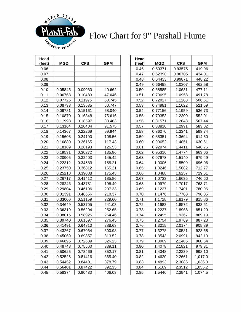
Flow Chart for 9” Parshall Flume
Head (feet) MGD CFS GPM
Head (feet) MGD CFS GPM
0.06 0.46 0.60371 0.93575 419.96 0.07 0.47 0.62390 0.96705 434.01 0.08 0.48 0.64433 0.99871 448.22 0.09 0.49 0.66498 1.0307 462.58 0.10 0.05845 0.09060 40.662 0.50 0.68585 1.0631 477.11 0.11 0.06763 0.10483 47.046 0.51 0.70695 1.0958 491.78 0.12 0.07726 0.11975 53.745 0.52 0.72827 1.1288 506.61 0.13 0.08733 0.13535 60.747 0.53 0.74981 1.1622 521.59 0.14 0.09781 0.15161 68.040 0.54 0.77156 1.1959 536.73 0.15 0.10870 0.16848 75.616 0.55 0.79353 1.2300 552.01 0.16 0.11998 0.18597 83.463 0.56 0.81571 1.2643 567.44 0.17 0.13164 0.20404 91.575 0.57 0.83810 1.2991 583.02 0.18 0.14367 0.22269 99.944 0.58 0.86070 1.3341 598.74 0.19 0.15606 0.24190 108.56 0.59 0.88351 1.3694 614.60 0.20 0.16880 0.26165 117.43 0.60 0.90652 1.4051 630.61 0.21 0.18189 0.28193 126.53 0.61 0.92974 1.4411 646.76 0.22 0.19531 0.30272 135.86 0.62 0.95316 1.4774 663.06 0.23 0.20905 0.32403 145.42 0.63 0.97678 1.5140 679.49 0.24 0.22312 0.34583 155.21 0.64 1.0006 1.5509 696.06 0.25 0.23750 0.36812 165.21 0.65 1.0246 1.5882 712.77 0.26 0.25218 0.39088 175.43 0.66 1.0488 1.6257 729.61 0.27 0.26717 0.41412 185.86 0.67 1.0733 1.6635 746.60 0.28 0.28246 0.43781 196.49 0.68 1.0979 1.7017 763.71 0.29 0.29804 0.46196 207.33 0.69 1.1227 1.7401 780.96 0.30 0.31391 0.48656 218.37 0.70 1.1476 1.7788 798.35 0.31 0.33006 0.51159 229.60 0.71 1.1728 1.8179 815.86 0.32 0.34649 0.53705 241.03 0.72 1.1982 1.8572 833.51 0.33 0.36319 0.56294 252.65 0.73 1.2237 1.8968 851.29 0.34 0.38016 0.58925 264.46 0.74 1.2495 1.9367 869.19 0.35 0.39740 0.61597 276.45 0.75 1.2754 1.9769 887.23 0.36 0.41491 0.64310 288.63 0.76 1.3015 2.0174 905.39 0.37 0.43267 0.67064 300.98 0.77 1.3278 2.0581 923.68 0.38 0.45069 0.69857 313.52 0.78 1.3543 2.0991 942.10 0.39 0.46896 0.72689 326.23 0.79 1.3809 2.1405 960.64 0.40 0.48748 0.75560 339.11 0.80 1.4078 2.1821 979.31 0.41 0.50625 0.78469 352.17 0.81 1.4348 2.2239 998.10 0.42 0.52526 0.81416 365.40 0.82 1.4620 2.2661 1,017.0 0.43 0.54452 0.84401 378.79 0.83 1.4893 2.3085 1,036.0 0.44 0.56401 0.87422 392.35 0.84 1.5169 2.3512 1,055.2 0.45 0.58374 0.90480 406.08 0.85 1.5446 2.3941 1,074.5
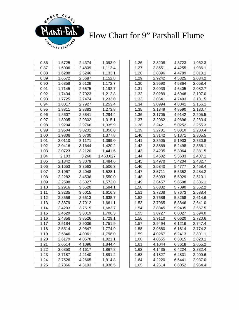
Flow Chart for 9” Parshall Flume
0.86 1.5725 2.4374 1,093.9 1.26 2.8208 4.3723 1,962.3 0.87 1.6006 2.4809 1,113.4 1.27 2.8551 4.4255 1,986.1 0.88 1.6288 2.5246 1,133.1 1.28 2.8896 4.4789 2,010.1 0.89 1.6572 2.5687 1,152.8 1.29 2.9242 4.5325 2,034.2 0.90 1.6858 2.6129 1,172.7 1.30 2.9590 4.5864 2,058.4 0.91 1.7145 2.6575 1,192.7 1.31 2.9939 4.6405 2,082.7 0.92 1.7434 2.7023 1,212.8 1.32 3.0289 4.6948 2,107.0 0.93 1.7725 2.7474 1,233.0 1.33 3.0641 4.7493 2,131.5 0.94 1.8017 2.7927 1,253.4 1.34 3.0994 4.8041 2,156.1 0.95 1.8311 2.8383 1,273.8 1.35 3.1349 4.8590 2,180.7 0.96 1.8607 2.8841 1,294.4 1.36 3.1705 4.9142 2,205.5 0.97 1.8905 2.9302 1,315.1 1.37 3.2062 4.9696 2,230.4 0.98 1.9204 2.9766 1,335.9 1.38 3.2421 5.0252 2,255.3 0.99 1.9504 3.0232 1,356.8 1.39 3.2781 5.0810 2,280.4 1.00 1.9806 3.0700 1,377.8 1.40 3.3142 5.1371 2,305.5 1.01 2.0110 3.1171 1,399.0 1.41 3.3505 5.1933 2,330.8 1.02 2.0416 3.1644 1,420.2 1.42 3.3869 5.2498 2,356.1 1.03 2.0723 3.2120 1,441.6 1.43 3.4235 5.3064 2,381.5 1.04 2.103 3.260 1,463.027 1.44 3.4602 5.3633 2,407.1 1.05 2.1342 3.3079 1,484.6 1.45 3.4970 5.4204 2,432.7 1.06 2.1653 3.3563 1,506.3 1.46 3.5340 5.4777 2,458.4 1.07 2.1967 3.4048 1,528.1 1.47 3.5711 5.5352 2,484.2 1.08 2.2282 3.4536 1,550.0 1.48 3.6083 5.5929 2,510.1 1.09 2.2598 3.5027 1,572.0 1.49 3.6457 5.6508 2,536.1 1.10 2.2916 3.5520 1,594.1 1.50 3.6832 5.7090 2,562.2 1.11 2.3235 3.6015 1,616.3 1.51 3.7208 5.7673 2,588.4 1.12 2.3556 3.6513 1,638.7 1.52 3.7586 5.8258 2,614.6 1.13 2.3879 3.7012 1,661.1 1.53 3.7965 5.8846 2,641.0 1.14 2.4203 3.7515 1,683.7 1.54 3.8345 5.9435 2,667.5 1.15 2.4529 3.8019 1,706.3 1.55 3.8727 6.0027 2,694.0 1.16 2.4856 3.8526 1,729.1 1.56 3.9110 6.0620 2,720.6 1.17 2.5184 3.9036 1,751.9 1.57 3.9494 6.1216 2,747.4 1.18 2.5514 3.9547 1,774.9 1.58 3.9880 6.1814 2,774.2 1.19 2.5846 4.0061 1,798.0 1.59 4.0267 6.2413 2,801.1 1.20 2.6179 4.0578 1,821.1 1.60 4.0655 6.3015 2,828.1 1.21 2.6514 4.1096 1,844.4 1.61 4.1044 6.3618 2,855.2 1.22 2.6850 4.1617 1,867.8 1.62 4.1435 6.4224 2,882.4 1.23 2.7187 4.2140 1,891.2 1.63 4.1827 6.4831 2,909.6 1.24 2.7526 4.2665 1,914.8 1.64 4.2220 6.5441 2,937.0 1.25 2.7866 4.3193 1,938.5 1.65 4.2614 6.6052 2,964.4
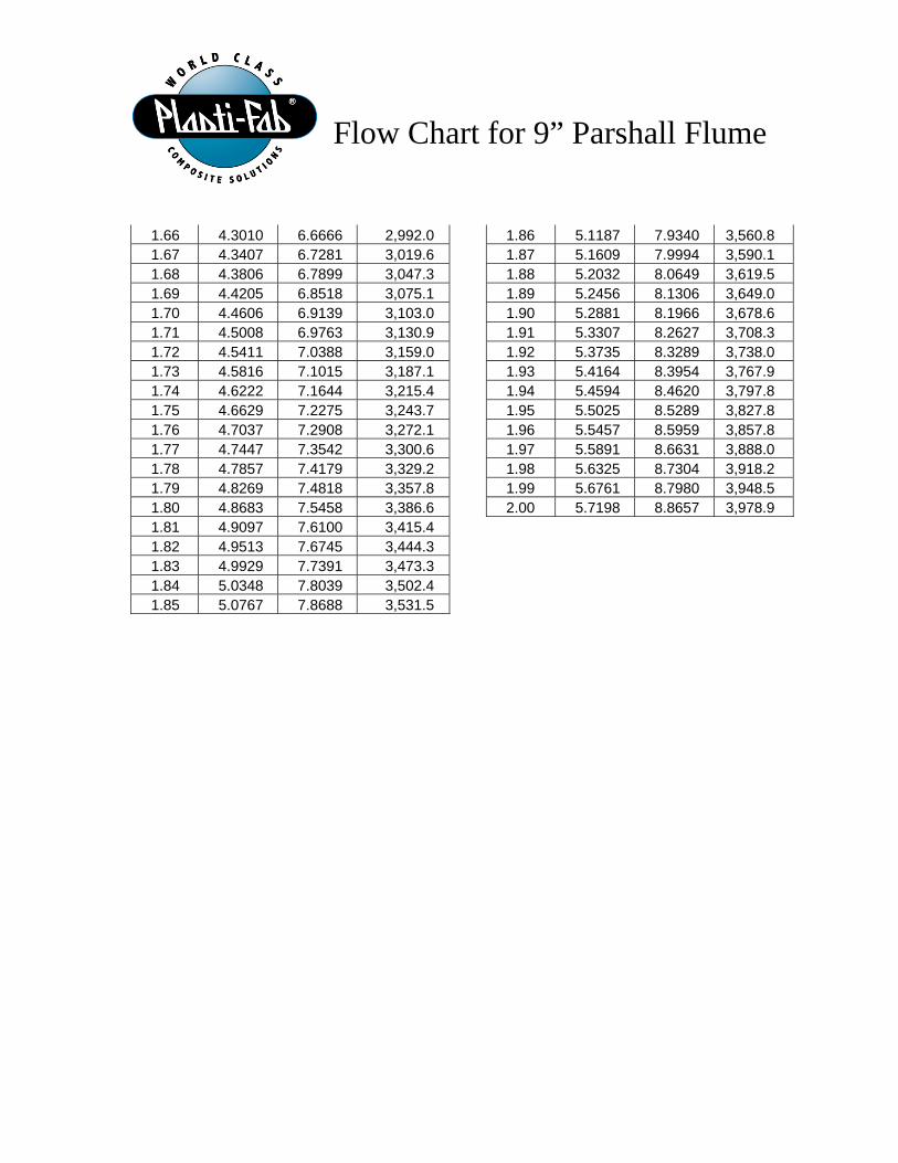
Flow Chart for 9” Parshall Flume
1.66 4.3010 6.6666 2,992.0 1.86 5.1187 7.9340 3,560.8 1.67 4.3407 6.7281 3,019.6 1.87 5.1609 7.9994 3,590.1 1.68 4.3806 6.7899 3,047.3 1.88 5.2032 8.0649 3,619.5 1.69 4.4205 6.8518 3,075.1 1.89 5.2456 8.1306 3,649.0 1.70 4.4606 6.9139 3,103.0 1.90 5.2881 8.1966 3,678.6 1.71 4.5008 6.9763 3,130.9 1.91 5.3307 8.2627 3,708.3 1.72 4.5411 7.0388 3,159.0 1.92 5.3735 8.3289 3,738.0 1.73 4.5816 7.1015 3,187.1 1.93 5.4164 8.3954 3,767.9 1.74 4.6222 7.1644 3,215.4 1.94 5.4594 8.4620 3,797.8 1.75 4.6629 7.2275 3,243.7 1.95 5.5025 8.5289 3,827.8 1.76 4.7037 7.2908 3,272.1 1.96 5.5457 8.5959 3,857.8 1.77 4.7447 7.3542 3,300.6 1.97 5.5891 8.6631 3,888.0 1.78 4.7857 7.4179 3,329.2 1.98 5.6325 8.7304 3,918.2 1.79 4.8269 7.4818 3,357.8 1.99 5.6761 8.7980 3,948.5 1.80 4.8683 7.5458 3,386.6 2.00 5.7198 8.8657 3,978.9 1.81 4.9097 7.6100 3,415.4 1.82 4.9513 7.6745 3,444.3 1.83 4.9929 7.7391 3,473.3 1.84 5.0348 7.8039 3,502.4 1.85 5.0767 7.8688 3,531.5
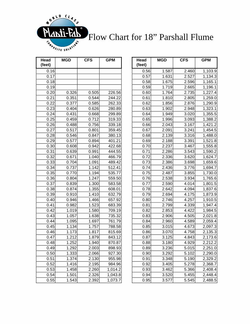
Flow Chart for 18” Parshall Flume
Head (feet)
MGD CFS GPM Head (feet)
MGD CFS GPM
0.16 0.56 1.587 2.460 1,103.9 0.17 0.57 1.631 2.527 1,134.3 0.18 0.58 1.675 2.596 1,165.1 0.19 0.59 1.719 2.665 1,196.1 0.20 0.326 0.505 226.56 0.60 1.764 2.735 1,227.4 0.21 0.351 0.544 244.22 0.61 1.810 2.805 1,259.0 0.22 0.377 0.585 262.33 0.62 1.856 2.876 1,290.9 0.23 0.404 0.626 280.89 0.63 1.902 2.948 1,323.1 0.24 0.431 0.668 299.89 0.64 1.949 3.020 1,355.5 0.25 0.459 0.712 319.33 0.65 1.996 3.093 1,388.2 0.26 0.488 0.756 339.18 0.66 2.043 3.167 1,421.2 0.27 0.517 0.801 359.45 0.67 2.091 3.241 1,454.5 0.28 0.546 0.847 380.13 0.68 2.139 3.316 1,488.0 0.29 0.577 0.894 401.21 0.69 2.188 3.391 1,521.8 0.30 0.608 0.942 422.68 0.70 2.237 3.467 1,555.8 0.31 0.639 0.991 444.55 0.71 2.286 3.543 1,590.2 0.32 0.671 1.040 466.79 0.72 2.336 3.620 1,624.7 0.33 0.704 1.091 489.42 0.73 2.386 3.698 1,659.6 0.34 0.737 1.142 512.41 0.74 2.436 3.776 1,694.7 0.35 0.770 1.194 535.77 0.75 2.487 3.855 1,730.0 0.36 0.804 1.247 559.50 0.76 2.538 3.934 1,765.6 0.37 0.839 1.300 583.58 0.77 2.590 4.014 1,801.5 0.38 0.874 1.355 608.01 0.78 2.642 4.094 1,837.6 0.39 0.910 1.410 632.79 0.79 2.694 4.175 1,873.9 0.40 0.946 1.466 657.92 0.80 2.746 4.257 1,910.5 0.41 0.982 1.523 683.39 0.81 2.799 4.339 1,947.4 0.42 1.019 1.580 709.19 0.82 2.853 4.422 1,984.5 0.43 1.057 1.638 735.32 0.83 2.906 4.505 2,021.8 0.44 1.095 1.697 761.79 0.84 2.960 4.589 2,059.4 0.45 1.134 1.757 788.58 0.85 3.015 4.673 2,097.3 0.46 1.173 1.817 815.69 0.86 3.070 4.758 2,135.3 0.47 1.212 1.879 843.12 0.87 3.125 4.843 2,173.6 0.48 1.252 1.940 870.87 0.88 3.180 4.929 2,212.2 0.49 1.292 2.003 898.93 0.89 3.236 5.015 2,251.0 0.50 1.333 2.066 927.30 0.90 3.292 5.102 2,290.0 0.51 1.374 2.130 955.98 0.91 3.348 5.190 2,329.2 0.52 1.416 2.195 984.96 0.92 3.405 5.278 2,368.7 0.53 1.458 2.260 1,014.2 0.93 3.462 5.366 2,408.4 0.54 1.501 2.326 1,043.8 0.94 3.520 5.455 2,448.4 0.55 1.543 2.392 1,073.7 0.95 3.577 5.545 2,488.5

Flow Chart for 18” Parshall Flume
0.96 3.635 5.635 2,528.9 1.36 6.212 9.628 4,321.0 0.97 3.694 5.725 2,569.6 1.37 6.282 9.737 4,370.0 0.98 3.753 5.816 2,610.4 1.38 6.353 9.847 4,419.1 0.99 3.812 5.908 2,651.5 1.39 6.424 9.957 4,468.5 1.00 3.871 6.000 2,692.8 1.40 6.495 10.067 4,518.0 1.01 3.931 6.093 2,734.3 1.41 6.566 10.178 4,567.8 1.02 3.991 6.186 2,776.1 1.42 6.638 10.289 4,617.7 1.03 4.051 6.279 2,818.0 1.43 6.710 10.401 4,667.8 1.04 4.112 6.373 2,860.2 1.44 6.782 10.513 4,718.1 1.05 4.173 6.468 2,902.6 1.45 6.855 10.625 4,768.6 1.06 4.234 6.563 2,945.3 1.46 6.928 10.738 4,819.2 1.07 4.295 6.658 2,988.1 1.47 7.001 10.851 4,870.1 1.08 4.357 6.754 3,031.2 1.48 7.074 10.965 4,921.2 1.09 4.420 6.850 3,074.4 1.49 7.148 11.079 4,972.4 1.10 4.482 6.947 3,117.9 1.50 7.222 11.194 5,023.8 1.11 4.545 7.045 3,161.6 1.51 7.296 11.309 5,075.4 1.12 4.608 7.142 3,205.5 1.52 7.370 11.424 5,127.2 1.13 4.671 7.241 3,249.7 1.53 7.445 11.540 5,179.2 1.14 4.735 7.340 3,294.0 1.54 7.520 11.656 5,231.3 1.15 4.799 7.439 3,338.5 1.55 7.595 11.773 5,283.7 1.16 4.864 7.539 3,383.3 1.56 7.671 11.890 5,336.2 1.17 4.928 7.639 3,428.3 1.57 7.747 12.007 5,388.9 1.18 4.993 7.739 3,473.4 1.58 7.823 12.125 5,441.8 1.19 5.058 7.840 3,518.8 1.59 7.899 12.243 5,494.8 1.20 5.124 7.942 3,564.4 1.60 7.975 12.362 5,548.1 1.21 5.190 8.044 3,610.2 1.61 8.052 12.481 5,601.5 1.22 5.256 8.147 3,656.2 1.62 8.129 12.600 5,655.1 1.23 5.322 8.249 3,702.4 1.63 8.207 12.720 5,708.9 1.24 5.389 8.353 3,748.8 1.64 8.284 12.840 5,762.8 1.25 5.456 8.457 3,795.3 1.65 8.362 12.961 5,816.9 1.26 5.523 8.561 3,842.1 1.66 8.440 13.082 5,871.2 1.27 5.591 8.666 3,889.1 1.67 8.518 13.204 5,925.7 1.28 5.659 8.771 3,936.3 1.68 8.597 13.325 5,980.4 1.29 5.727 8.876 3,983.7 1.69 8.676 13.447 6,035.2 1.30 5.795 8.982 4,031.3 1.70 8.755 13.570 6,090.2 1.31 5.864 9.089 4,079.1 1.71 8.834 13.693 6,145.4 1.32 5.933 9.196 4,127.1 1.72 8.914 13.816 6,200.8 1.33 6.002 9.303 4,175.3 1.73 8.994 13.940 6,256.3 1.34 6.072 9.411 4,223.7 1.74 9.074 14.064 6,312.0 1.35 6.141 9.519 4,272.3 1.75 9.154 14.189 6,367.9
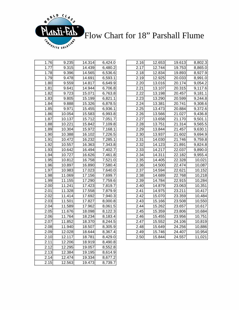
Flow Chart for 18” Parshall Flume
1.76 9.235 14.314 6,424.0 2.16 12.653 19.613 8,802.3 1.77 9.315 14.439 6,480.2 2.17 12.744 19.753 8,865.0 1.78 9.396 14.565 6,536.6 2.18 12.834 19.893 8,927.9 1.79 9.478 14.691 6,593.1 2.19 12.925 20.033 8,991.0 1.80 9.559 14.817 6,649.9 2.20 13.016 20.174 9,054.2 1.81 9.641 14.944 6,706.8 2.21 13.107 20.315 9,117.6 1.82 9.723 15.071 6,763.8 2.22 13.198 20.457 9,181.1 1.83 9.805 15.199 6,821.1 2.23 13.290 20.599 9,244.8 1.84 9.888 15.326 6,878.5 2.24 13.381 20.741 9,308.6 1.85 9.971 15.455 6,936.1 2.25 13.473 20.884 9,372.6 1.86 10.054 15.583 6,993.8 2.26 13.566 21.027 9,436.8 1.87 10.137 15.712 7,051.7 2.27 13.658 21.170 9,501.1 1.88 10.221 15.842 7,109.8 2.28 13.751 21.314 9,565.5 1.89 10.304 15.972 7,168.1 2.29 13.844 21.457 9,630.1 1.90 10.388 16.102 7,226.5 2.30 13.937 21.602 9,694.9 1.91 10.472 16.232 7,285.1 2.31 14.030 21.746 9,759.8 1.92 10.557 16.363 7,343.8 2.32 14.123 21.891 9,824.8 1.93 10.642 16.494 7,402.7 2.33 14.217 22.037 9,890.0 1.94 10.727 16.626 7,461.8 2.34 14.311 22.182 9,955.4 1.95 10.812 16.758 7,521.0 2.35 14.405 22.328 10,021 1.96 10.897 16.890 7,580.4 2.36 14.500 22.474 10,087 1.97 10.983 17.023 7,640.0 2.37 14.594 22.621 10,152 1.98 11.069 17.156 7,699.7 2.38 14.689 22.768 10,218 1.99 11.155 17.290 7,759.6 2.39 14.784 22.915 10,284 2.00 11.241 17.423 7,819.7 2.40 14.879 23.063 10,351 2.01 11.328 17.558 7,879.9 2.41 14.975 23.211 10,417 2.02 11.414 17.692 7,940.3 2.42 15.070 23.359 10,484 2.03 11.501 17.827 8,000.8 2.43 15.166 23.508 10,550 2.04 11.589 17.962 8,061.5 2.44 15.262 23.657 10,617 2.05 11.676 18.098 8,122.3 2.45 15.359 23.806 10,684 2.06 11.764 18.234 8,183.4 2.46 15.455 23.956 10,751 2.07 11.852 18.370 8,244.5 2.47 15.552 24.106 10,819 2.08 11.940 18.507 8,305.9 2.48 15.649 24.256 10,886 2.09 12.028 18.644 8,367.4 2.49 15.746 24.407 10,954 2.10 12.117 18.781 8,429.0 2.50 15.844 24.557 11,021 2.11 12.206 18.919 8,490.8 2.12 12.295 19.057 8,552.8 2.13 12.384 19.195 8,614.9 2.14 12.474 19.334 8,677.2 2.15 12.563 19.473 8,739.7
9"2"
FLA
NG
E
18"
2" F
LAN
GE
1'-0"2'-10" 1'-6"
1'-1118"
2'-0"4'-778" 3'-0"
1'-1
05 8"
3'-4
3 8"
1'-3
"
2'-6
"
3'-2"
1'-978" 5'-4"
9'-778"
3'-6
"C
HAN
NEL
WID
TH
3'-1
03 8"BL
OC
KOUT
WID
TH
FLOWFLOW
A
4
5
21
3
6
18" PARSHALL SONIC BRACKET MOUNTING CHANNEL POSITION (FOR FUTURE USE)
INTEGRAL HEADGAUGE HA
7 7 8
9" & 18" PARSHALL SONIC BRACKET MOUNTING CHANNEL (USE FOR FUTURE USE ON 18")
6
7
7
8
41 2"
9"
2'-6
"
2'-9
"
1'-0
"1'
-0"
3'-0
"2"
FLA
NG
E
3'-3
"
1'-2
"
2'-6
"
SONIC BRACKET ASSEMBLY
1"
1"
DETAIL A SCALE 2 : 7
CHANNEL SIDE BLOCKOUT AND GROUT BY OTHERS
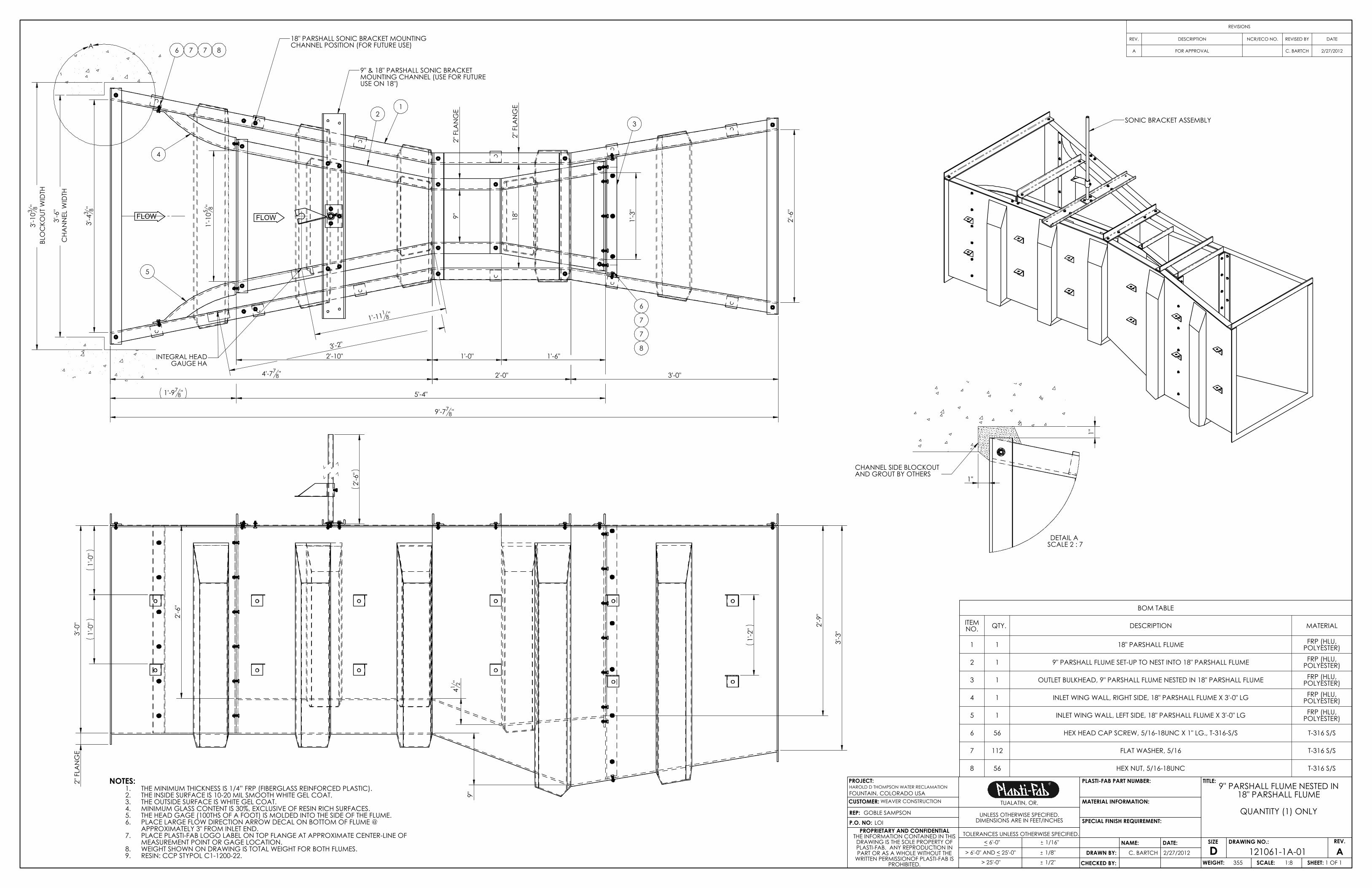
NOTES:THE MINIMUM THICKNESS IS 1/4” FRP (FIBERGLASS REINFORCED PLASTIC).1.THE INSIDE SURFACE IS 10-20 MIL SMOOTH WHITE GEL COAT.2.THE OUTSIDE SURFACE IS WHITE GEL COAT.3.MINIMUM GLASS CONTENT IS 30%, EXCLUSIVE OF RESIN RICH SURFACES.4.THE HEAD GAGE (100THS OF A FOOT) IS MOLDED INTO THE SIDE OF THE FLUME.5.PLACE LARGE FLOW DIRECTION ARROW DECAL ON BOTTOM OF FLUME @ 6.APPROXIMATELY 3" FROM INLET END.PLACE PLASTI-FAB LOGO LABEL ON TOP FLANGE AT APPROXIMATE CENTER-LINE OF 7.MEASUREMENT POINT OR GAGE LOCATION.WEIGHT SHOWN ON DRAWING IS TOTAL WEIGHT FOR BOTH FLUMES.8.RESIN: CCP STYPOL C1-1200-22.9.
BOM TABLE
ITEM NO. QTY. DESCRIPTION MATERIAL
1 1 18" PARSHALL FLUME FRP (HLU, POLYESTER)
2 1 9" PARSHALL FLUME SET-UP TO NEST INTO 18" PARSHALL FLUME FRP (HLU, POLYESTER)
3 1 OUTLET BULKHEAD, 9" PARSHALL FLUME NESTED IN 18" PARSHALL FLUME FRP (HLU, POLYESTER)
4 1 INLET WING WALL, RIGHT SIDE, 18" PARSHALL FLUME X 3'-0" LG FRP (HLU, POLYESTER)
5 1 INLET WING WALL, LEFT SIDE, 18" PARSHALL FLUME X 3'-0" LG FRP (HLU, POLYESTER)
6 56 HEX HEAD CAP SCREW, 5/16-18UNC X 1" LG., T-316-S/S T-316 S/S
7 112 FLAT WASHER, 5/16 T-316 S/S
8 56 HEX NUT, 5/16-18UNC T-316 S/S
REVISIONS
REV. DESCRIPTION NCR/ECO NO. REVISED BY DATE
A FOR APPROVAL C. BARTCH 2/27/2012
PROPRIETARY AND CONFIDENTIALTHE INFORMATION CONTAINED IN THIS DRAWING IS THE SOLE PROPERTY OF PLASTI-FAB. ANY REPRODUCTION IN PART OR AS A WHOLE WITHOUT THE
WRITTEN PERMISSIONOF PLASTI-FAB IS PROHIBITED.
DSIZE REV.
ASCALE: CHECKED BY:
DRAWING NO.:
REP:P.O. NO:
PROJECT:
CUSTOMER:
DATE:DRAWN BY: 121061-1A-01
WEAVER CONSTRUCTION
LOI
1:8WEIGHT: 355 SHEET: 1 OF 1
2/27/2012
NAME:
SPECIAL FINISH REQUIREMENT:
MATERIAL INFORMATION:
PLASTI-FAB PART NUMBER: TITLE:
UNLESS OTHERWISE SPECIFIED.DIMENSIONS ARE IN FEET/INCHES
TOLERANCES UNLESS OTHERWISE SPECIFIED.< 6'-0"
> 25'-0"
1/16"
1/8"
1/2"
> 6'-0" AND < 25'-0" C. BARTCH
TUALATIN, OR.
GOBLE SAMPSON
9" PARSHALL FLUME NESTED IN 18" PARSHALL FLUME
QUANTITY (1) ONLY
HAROLD D THOMPSON WATER RECLAMATIONFOUNTAIN, COLORADO USA

LIMITED WARRANTY
Every effort is made to assure that our customers receive the highest quality merchandise, free of any defects in materials and workmanship. This merchandise has been designed for use in accordance with the project specifications, and the standards and/or instructions recommended by this catalog, or other written quotation of this firm. However, no warranty, expressed or implied, is made other than as follows: When installed and operated correctly, Plasti-Fab guarantees this merchandise for 25 full years against functional failure due to corrosion of composite materials, and 24 full months against failure due to any defects in material and workmanship. Such warranty can only be enforced by the product end user. During the warranty period any defects in material or workmanship will be repaired or replaced at Plasti-Fab, Inc.’s option at no cost to the end user. Warranty specifically excludes damage due to improper handling, storage, misuse or neglect. Measure of damage is the price of defective material only. No charges for labor or expense required to remove or replace defective material, or for any consequential damages, will be allowed. Any implied warranty of merchantability or fitness is limited to the 24 months duration of this written warranty. To the extent allowed by law, neither Plasti-Fab, Inc. nor its selling dealer or agent shall have any responsibility for loss of use of the product, loss of time, commercial loss or consequential damages. A “pass-through” warranty is offered for products that are manufactured by other companies and furnished as a component part of a Plasti-Fab product. Typical examples of such products include, but are not limited to: air conditioning units, electric actuators and gearboxes, thermostats, solenoids, gages, controllers, heaters, blowers, and fans. Warranties on these products are pass-through, meaning the equipment warranty will be limited to that offered by the equipment’s original manufacturer. This warranty gives specific legal rights. Other rights vary from state to state and by country. In the event a warranted product is believed defective, please notify Plasti-Fab, Inc. Refer to Plasti-Fab job number, print number, installation location, address and telephone numbers listed in the O&M manual when requesting assistance. Provide date purchased and copy of invoice or shipping documents if possible. It is the policy of this company to encourage the settlement of disputes in an informal manner, and if such disputes arise over a warranty claim, an informal dispute settlement mechanism can be agreed upon at that time.
Please consult your local representative or contact Plasti-Fab, Inc., PO Box 100, Tualatin Oregon 97062 PHONE 503.692.5460 FAX 503.692.1145 E-MAIL [email protected] WEB WWW.PLASTI-FAB.COM
Page 1 of 1