Embed Size (px)
Citation preview
Introduction to The Fabry-perot for the Integrated Direct Detection Lidar: FIDDLIntroduction to The Fabry-perot for the Integrated Direct Detection Lidar: FIDDL
S. Tucker, Ball Aerospace & Technologies Corp.
Working Group on Space-Based Wind Lidar
17 October 2012
S. Tucker, Ball Aerospace & Technologies Corp.
Working Group on Space-Based Wind Lidar
17 October 2012
Working Group on Space-Based Wind Lidar, 16-18 October 2012 - Boulder, CO
Introduction: FIDDL & OAWL
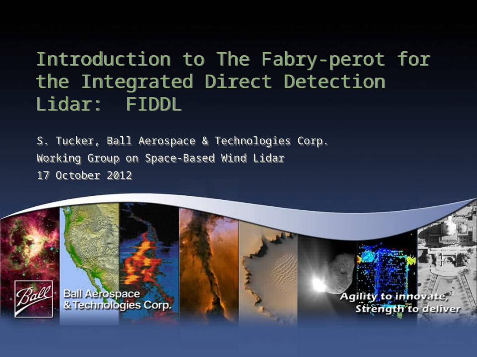
The Fabry-perot for the Integrated Direct Detection Lidar (FIDDL) is funded under the NASA ESTO Advanced Component Technologies (ACT) program
FIDDL fits in the MIDDL: between the OAWL (Optical Autocovariance Wind Lidar) telescope and the OAWL receiver interferometer
FIDDL is designed to provide wind estimates from molecular return at 355 nm, and then reflect the aerosol portion of the spectrum (center) on to OAWL
pg 2
OAWL IIPFIDDL ACT
One system, one laser, global winds & aerosols.
Working Group on Space-Based Wind Lidar, 16-18 October 2012 - Boulder, CO
The FIDDL team (more to come…)
Electrical…………………….... Mike Adkins Co-I, Optical…………………. Tom Delker Optical……………………….. Bob Pierce Models & Control Systems…… Mike Lieber PI, PM, Modeling/Algorithms… Sara Tucker Management Support…………Carl Weimer
Ray Demara
pg 3
Working Group on Space-Based Wind Lidar, 16-18 October 2012 - Boulder, CO
FIDDL Primer: bandwidth of atmospheric lidar return
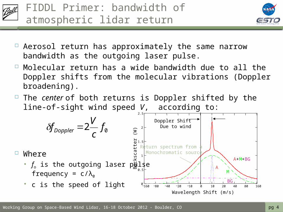
Aerosol return has approximately the same narrow bandwidth as the outgoing laser pulse.
Molecular return has a wide bandwidth due to all the Doppler shifts from the molecular vibrations (Doppler broadening).
The center of both returns is Doppler shifted by the line-of-sight wind speed V, according to:
Where fo is the outgoing laser pulse
frequency = c/λ0
c is the speed of light
Doppler ShiftDue to wind
AM
A+M+BG
BG
Return spectrum from aMonochromatic source
160 80 40 20 10 0 10 20 40 80 1600
0.5
1
1.5
2
2.5
Wavelength Shift (m/s)
Ba
cksc
att
er
(W)02 f
c
VfDoppler
pg 4
Working Group on Space-Based Wind Lidar, 16-18 October 2012 - Boulder, CO
FIDDL Requirements
Overall Science Goals: Pushing for <1 m/s precision in the wind estimate (ground tests)
For low aerosol loading conditions. 1-2 second time span (TBR based on laser PRF, SNR, etc.)
<1 m/s accuracy in the wind estimate Will aim to verify with OAWL in the overlap (low aerosol) Eventual “synergy” with HOAWL (separate signal processing task) may be
used to lessen the impact of aerosol signals through knowledge of the Ra/m
Design approach - without risking the technology demonstration Best effort to build the system for aircraft Best effort to make use of components with path-to-space Best effort to design the physical system to fit with current AND
future OAWL systems.
pg 5
Working Group on Space-Based Wind Lidar, 16-18 October 2012 - Boulder, CO
FIDDL Tasks
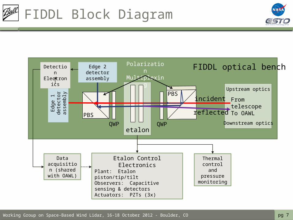
FIDDL is a new receiver component to be added to OAWL. Thus the build requires: Etalon optical design & build Etalon gap control design & build (biggest part!) Input/output optics – to receive light from the telescope, and pass
reflected light off to OAWL – design and build. Polarization multiplexing and detector installation Data analysis algorithms and calibration techniques
As a lidar, most components already exist as part of OAWL Telescope Laser Data acquisition system Detector design
pg 6
Working Group on Space-Based Wind Lidar, 16-18 October 2012 - Boulder, CO
From telescopeTo OAWL
FIDDL Block Diagram
PBS
PBS
etalonQWPQWP
incident
reflected
Edge 2 detector assembly
Edge
1 d
etec
tor
asse
mbl
y
Detection Electronics
Data acquisition
(shared with OAWL)
Etalon Control ElectronicsPlant: Etalon piston/tip/tiltObservers: Capacitive sensing & detectorsActuators: PZTs (3x)
Upstream optics
Downstream optics
pg 7
FIDDL optical bench
Thermal control and
pressure monitoring
Polarization Multiplexing
Working Group on Space-Based Wind Lidar, 16-18 October 2012 - Boulder, CO
FIDDL: Fabry-Perot Basics
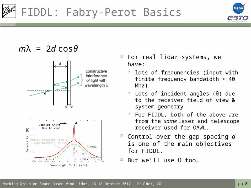
For real lidar systems, we have: lots of frequnencies (input with
finite frequency bandwidth > 40 Mhz)
Lots of incident angles (θ) due to the receiver field of view & system geometry
For FIDDL, both of the above are from the same laser and telescope receiver used for OAWL.
Control over the gap spacing d is one of the main objectives for FIDDL.
But we’ll use θ too…
mλ = 2d cosθ
Doppler ShiftDue to wind
AM
A+M+BG
BG
Return spectrum from aMonochromatic source
160 80 40 20 10 0 10 20 40 80 1600
0.5
1
1.5
2
2.5
Wavelength Shift (m/s)
Bac
ksca
tter
(W
)
pg 8
Working Group on Space-Based Wind Lidar, 16-18 October 2012 - Boulder, CO
FIDDL Primer: General Double Edge Technique
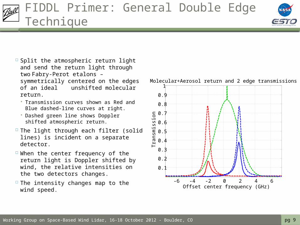
Split the atmospheric return light and send the return light through two Fabry-Perot etalons – symmetrically centered on the edges of an ideal unshifted molecular return. Transmission curves shown as Red and
Blue dashed-line curves at right. Dashed green line shows Doppler
shifted atmospheric return.
The light through each filter (solid lines) is incident on a separate detector.
When the center frequency of the return light is Doppler shifted by wind, the relative intensities on the two detectors changes.
The intensity changes map to the wind speed.
pg 9
-6 -4 -2 0 2 4 6
0.1
0.2
0.3
0.4
0.5
0.6
0.7
0.8
0.9
1
Offset center frequency (GHz)
Tra
nsm
issi
on
Molecular+Aerosol return and 2 edge transmissions
Working Group on Space-Based Wind Lidar, 16-18 October 2012 - Boulder, CO
FIDDL Primer: Fabry-Perot 1st pass
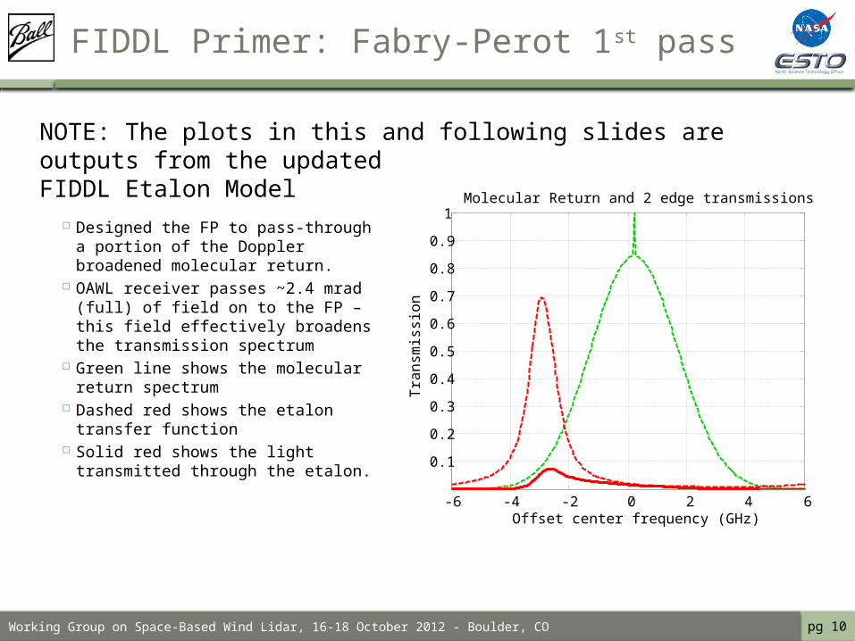
Designed the FP to pass-through a portion of the Doppler broadened molecular return.
OAWL receiver passes ~2.4 mrad (full) of field on to the FP – this field effectively broadens the transmission spectrum
Green line shows the molecular return spectrum
Dashed red shows the etalon transfer function
Solid red shows the light transmitted through the etalon.
pg 10
NOTE: The plots in this and following slides are outputs from the updatedFIDDL Etalon Model
-6 -4 -2 0 2 4 6
0.1
0.2
0.3
0.4
0.5
0.6
0.7
0.8
0.9
1
Offset center frequency (GHz)
Tra
nsm
issi
on
Molecular Return and 2 edge transmissions
Working Group on Space-Based Wind Lidar, 16-18 October 2012 - Boulder, CO
FIDDL Primer: Fabry-Perot 2nd pass
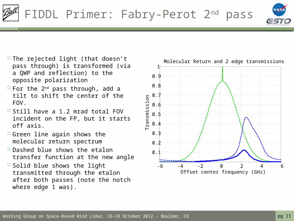
The rejected light (that doesn’t pass through) is transformed (via a QWP and reflection) to the opposite polarization
For the 2nd pass through, add a tilt to shift the center of the FOV.
Still have a 1.2 mrad total FOV incident on the FP, but it starts off axis.
Green line again shows the molecular return spectrum
Dashed blue shows the etalon transfer function at the new angle
Solid blue shows the light transmitted through the etalon after both passes (note the notch where edge 1 was).
pg 11
-6 -4 -2 0 2 4 6
0.1
0.2
0.3
0.4
0.5
0.6
0.7
0.8
0.9
1
Offset center frequency (GHz)
Tra
nsm
issi
on
Molecular Return and 2 edge transmissions
Working Group on Space-Based Wind Lidar, 16-18 October 2012 - Boulder, CO
Unique characteristics of the FIDDL approach…
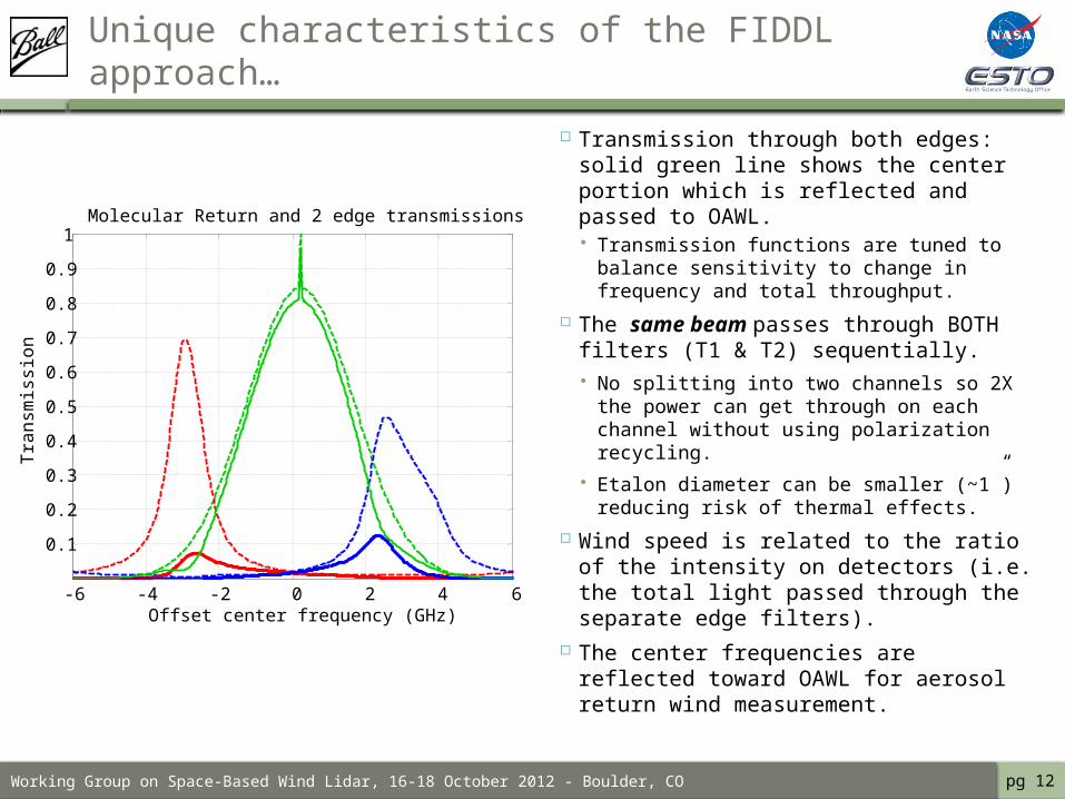
Transmission through both edges: solid green line shows the center portion which is reflected and passed to OAWL. Transmission functions are tuned to
balance sensitivity to change in frequency and total throughput.
The same beam passes through BOTH filters (T1 & T2) sequentially. No splitting into two channels so 2X the
power can get through on each channel without using polarization recycling.
Etalon diameter can be smaller (~1”) reducing risk of thermal effects.
Wind speed is related to the ratio of the intensity on detectors (i.e. the total light passed through the separate edge filters).
The center frequencies are reflected toward OAWL for aerosol return wind measurement.
pg 12
-6 -4 -2 0 2 4 6
0.1
0.2
0.3
0.4
0.5
0.6
0.7
0.8
0.9
1
Offset center frequency (GHz)
Tra
nsm
issi
on
Molecular Return and 2 edge transmissions
Working Group on Space-Based Wind Lidar, 16-18 October 2012 - Boulder, CO
FIDDL Requirements: Etalon Gap Control
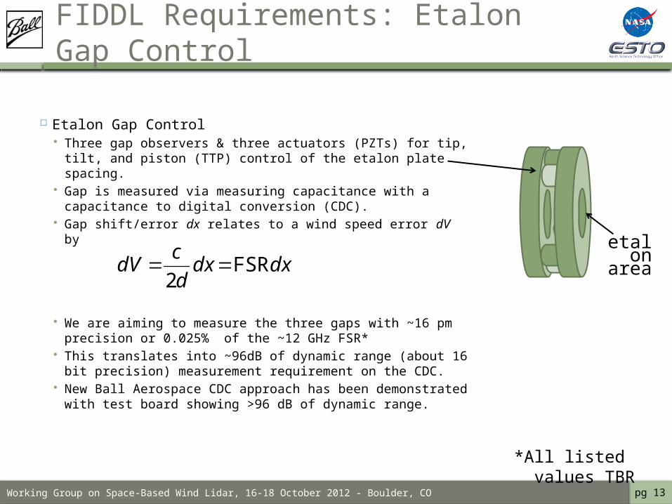
Etalon Gap Control Three gap observers & three actuators (PZTs) for tip,
tilt, and piston (TTP) control of the etalon plate spacing.
Gap is measured via measuring capacitance with a capacitance to digital conversion (CDC).
Gap shift/error dx relates to a wind speed error dV by
We are aiming to measure the three gaps with ~16 pm precision or 0.025% of the ~12 GHz FSR*
This translates into ~96dB of dynamic range (about 16 bit precision) measurement requirement on the CDC.
New Ball Aerospace CDC approach has been demonstrated with test board showing >96 dB of dynamic range.
pg 13
dxdxd
cdV FSR
2
etalon
area
*All listed values TBR
Working Group on Space-Based Wind Lidar, 16-18 October 2012 - Boulder, CO
FIDDL Modeling & Analysis
Upgraded and added-to the Ball etalon model(s) Matlab etalon model (originally built on Ball funds) updated and geared
to model FIDDL Paired with the OAWL radiometric model (RMM) which
includes laser transmitter, atmosphere, telescope, photo-detectors, etc. allows for SNR modeling at different altitudes, with varying aerosol/molecular
scattering ratios and molecular bandwidths. may be easily updated to integrate new atmospheres
All input angles in the FIDDL approach are represented (one dimensional tilt tuning plus two-dimensional input field of view)
Developed preliminary wind retrieval algorithms for the unique FIDDL system Modeled output sensitivity to wind speeds revealing the optimal
placement for the lower-finesse filter transmission.
Using the models (with the CDC test results) to finalize etalon specifications (trades/balancing of requirements).
pg 14
Working Group on Space-Based Wind Lidar, 16-18 October 2012 - Boulder, CO
Model Results: optimum edge filter placement
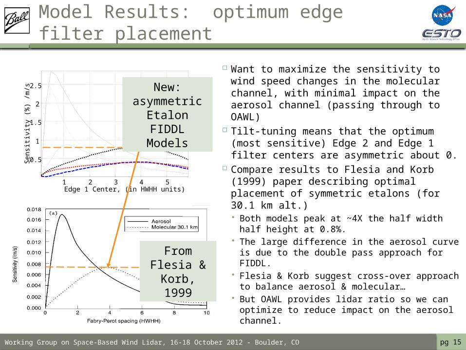
Want to maximize the sensitivity to wind speed changes in the molecular channel, with minimal impact on the aerosol channel (passing through to OAWL)
Tilt-tuning means that the optimum (most sensitive) Edge 2 and Edge 1 filter centers are asymmetric about 0.
Compare results to Flesia and Korb (1999) paper describing optimal placement of symmetric etalons (for 30.1 km alt.) Both models peak at ~4X the half width
half height at 0.8%. The large difference in the aerosol curve is
due to the double pass approach for FIDDL. Flesia & Korb suggest cross-over approach
to balance aerosol & molecular… But OAWL provides lidar ratio so we can
optimize to reduce impact on the aerosol channel.
pg 15
1 2 3 4 5
0.5
1
1.5
2
2.5
Edge 1 Center, (in HWHH units)
Sen
sitiv
ity (
%)
/m/s
From Flesia & Korb, 1999
New: asymmetric Etalon FIDDL
Models
Working Group on Space-Based Wind Lidar, 16-18 October 2012 - Boulder, CO
In conclusion…
The FIDDL ACT is underway with system models with field and angle tuning radiometric models to understand SNR new CDC designs for etalon gap sensing and control
Next major step: specifying the etalon and finding allowed vendor.
Expect to have a FIDDL PDR in November Plan to start electronics and optical hardware
builds early Spring 2013.
pg 16