Embed Size (px)
Citation preview

IEEE TRANSACTIONS ON COMMUNICATIONS, VOL. COM-30, NO. S, MAY 1982 855
Theory of Spread-Spectrum Communications-A Tutorial RAYMOND L. PICKHOLTZ, FELLOW, UEE, DONALD L. SCHILLINO, FELLOW, IEEE,
AND LAURENCE B. MILSTEIN, S~NIOR MEMBER, IEEE
Abstract--Spread-spectrum communications, with its inherent iJtterference attenuation capability, has over the years become an increasingly popular technique for use in many different system1:. Applications range from antijam systems, to code division multiple access systems, to systems designed to combat multipath. It is tbe intention of this paper to provide a tutorial treatment of the theory <·f spread-spectrum communiCations, including a discussion on tbe applications referred to above, on the properties of commoll spreading sequences, and on techniques that can be used for ac -quisition and tracking.
I. INTRODUCTION
SPREAD-spectrum systems have been developed since about the mid-1950's. The initial applications have bee1
to military antijamming tactical communications, to guidance systems, to experimental aritimultipath systems, and t J
other applications [1]. A definition of spread spectrun that adequately reflects the characteristics of this technique is as follows:
"Spread spectrum is a means of transmission in which the signal occupies a bandwidth in excess of the minimum necessary to send the information; the band spread is accomplished by means of a code which is independent of the data, and a synchronized reception with the code at the receiver is used for despreading and subsequent data recovery."
Under this definition, standard modulation schemes such as FM and PCM which also spread the spectrum of an information signal do not qualify as spread spectrum.
There are many reasons for spreading the spectrum, and if done properly, a multiplicity of benefits· can accrue simultaneously, Some of these are
• Antijaffilning • Antiinterference • Low probability of intercept • Multiple user random access communications with selec·
tive addressing capability • High resolution ranging • Accurate universal timing.
Manuscript received December 22, 1981; revised February 16, 1982 R. L. Pickholtz is with the Department of Electrical Engineering anc
Computer Science, George Washington University, Washington, DC' 20052.
D. L. Schilling is with the Department of Electricai Engineering City College of New York, New York, NY 10031.
L. B. Milstein is with the Department of Electrical Engineering anc Computer Science, University of California at San Diego, La Jolla CA 92093.
The means by which the spectrum is spread is crucial. Several of the techniques are "direct-sequence" .riwdulation in which a fast pseudorandomly generated sequence causes phase transitions in the carrier containing data, "frequency hopping,'' in which the carrier is caused to shift frequency in a pseudorandom way, arid "time hopping,'' wherein bursts of signal are initiated at pseudorandom times. Hybrid combinations of these techniques are frequently used.
Although the current applications for spread spectrum continue to be primarily for inilit.aty communications, there is a growing interest in the use of this technique for mobile radio networks (radio telephony, packet radio, and amateur radio), timing and positioning systems, some specialized applications in satellites, etc. While the use of spread spectrum naturally means that each transmission utilizes a large amount of spectrum, this may be compensated for by the interference reduction capability inherent in the use of spread-spectrum techniques, so that a considerable number of users might share the same spectral band. There are no easy answers to the question of whether spread spectrum is better or worse than conventional methods for such multiuser channels. However, the one issue that is clear is that spread spectrum affords an opportunity to give a desired signal a power advantage over many types of interference, including most intentional interference (i.e;, jamrriing). In this paper, we confine ourselves to principles related to the design and analysis of various important aspects of a spread-spectrum communications system. The emphasis will be on directsequence techniques artd frequency-hopping techniques.
The major systems questions associated with the design of a spread-spectrum system are: How is performance measured? What kind of coded sequences are used and what are their properties? How much jamming/interference protection is achievable? What is the performance of any user pair in an environment where there are many spread spectrum users (code division multiple access)? To what extent does spread spectrum reduce the effects of multipath? How is the relative timing of the transmitter-receiver codes established (acquisition) and retained (tracking)?
It is the aim of this tutorial paper to answer some of these questions succinctly, and in the process, offer some insights into this important communications technique. A glossary of the symbols used is provided at the end of the paper.
II. SPREADING AND DIMENSIONALITYPROCESSING GAIN
A fundamental issue in spread spectrum is how this technique affords protection against interfering signals with
0090-6778/82/0500-0.~55$00.75 © 1982 IEEE
Silver Spring Ex. 1036 Page 1

856 IEEE TRANSACTIONS ON COMMUNICATIONS, VOL. COM-30, NO.5, MAY 1982
fmite power. The underlying principle is that of distributing a relatively low dimensional (defined below) data signal in a high dimensional environment so that a jammer with a fixed amount of total power (intent on maximum disruption of communications) is obliged to either spread that fixed power over. all the coordinates, thereby inducing just a little irtterference in each coordinate, or else place all of the power into a small subspace, leaving the remainder of the space interference free.
A brief discussion of a classical problem of signal detection in noise should clarify the emphasis on fmite interference power. The "standard" problem of digital transmissicin.in the presence of thermal noise is one where both transmitter and receiver kno~ the set of M signaling waveforms {S;(t), 0.;;;; t.;;;; T; 1 .;;;; i ..;;M}. The transmitter selects one of the waveforms every T seconds to provide a data rate of log2M/T bits/s. If, for example, S;(t) is sent, the receiver observes r(t) = S;(t) + nw(t) over [0, T] where nw(t) is additive, white Gaussian noise (AWGN) with (two-sided) power spectral density f/o/2 W/Hz.
It is well known [3] that the signal set can be completely specified by a linear combination of no more than D .;;;; M orthonormal basis functions (see below), and that although the white noise, similarly expanded, requires an infmite number of terms, only those within the signal space are "relevant" [3] . We say that the signal set defined above is D~dimensional if the minimum number of orthonormal basis functions required to define all the signals is D. D can be shown to be [3] approximately 2BDT where BD is the total (approximate) bandwidth occupancy of the signal set. The optimum (minimum probability of error) detector in AWGN consists of a bank of cotrelators or filters matched to each signal, and the decision as to which was the transmitted signal corresponds to the largest output of the correlators.
Given a specific signal design, the performance of such a system is well known to be a function only of the ratio of the energy per bit to the noise spectral density. Hence, against white noise (which has infinite power and constant energy in every direction), the use of spreading (large 2BDT) offers no help. The situation is quite different, however, when the "noise" is a jammer with a fixed finite power. In this case, the effect of spreading the signal bandwidth so that the jammer is uncertain as to where in the large space the components are is often to force the jammer to distribute its finite power over many different coordinates of the signal space.
Since the desired signal can be "collapsed" by correlating the signal at the receiver with the known code, the desired signal is protected against a jammer in the sense that it has an effective power advantage relative to the jammer. This power advantage is often proportional to the ratio of the dimensionality of the space of code sequences to that of the data signal. It is necessary, of course, to "hide" the pattern by which the data are spread. This is usually done With a pseudonoise (PN) sequence which has desired randonmess properties and which is available to the cooperating transmitter and receiver, but denied to other undesirable users of the common spectrum.
A general model which conveys these ideas, but which
uses random (rather than pseuodrandom) sequences, is as follows. Suppose we consider transmission by means of D equiprobable and equienergy orthogonal signals imbedded in an n-dimensional space so that
n
S;(t) = ~ S;krf>k(t); t..;;i..;;D; o..;;t..;; r k= 1
where
and where {rf>k(t); 1.;;;; k.;;;; n} is an orthonormal basis spanning the space, i.e.,
The average energy of each signal is
l=m
1 =I= m.
t..;;i ..;;n (1)
(the overbar is the expected value over the ensemble). In order to hide this D-dimensional signal set in the larger
n-dimensional space, choose the sequence of coefficitents sik independently (say' by flipping a fair coin if a binary alphabet is used) such that they have zero mean and correlation
l..;;i<D. (2)
Thus, the signals, which are also assumed to be known to the receiver (i.e., we assume the receiver had been supplied the sequences S;k before transmission) but denied to the jammer, have their respective energies uniforrilly distributed over the n basis directions as far as the jammer is concerned.
Consider next a jammer
n
J(t) = ~ hrf>k(t); O<t<T (3) k=1
with total energy
(4)
which is added to the signal with the intent to disrupt communications. Assume that the jammer's signal is independent of the desired signal. One of the jammer's objectives is to dev1se a strategy for selecting the components J k 2 of his fixed total energy EJ so as to minimize the postprocessing signal-to-noise ratio (SNR) at the receiver.
Silver Spring Ex. 1036 Page 2

PICKHOLTZ eta/.: THEORY OF SPREAD-SPECTRUM COMMUNI::ATIONS 857
The received signal
r(t) = S;(t) + J(t) (5)
is correlated with the (known) signals so that the output of the ith correlator is
(6)
Hence,
n
E(U; IS;)=~ S;k 2 =Es ('1) k=1
since the second term averages to zero. Then, since the signds are equiprobable,
Es E(U;)=D.
Similarly, using (1) and (2),
var(U;IS;)= ~ J~1S;kSu k,/
and
n
= ~ Jk2sik2 k=1
(H)
(<1)
(10)
A measure of performance is the signal-to-noise ratio defined as
E 2 (U) Es n SNR= =-·-·
var (U) EJ D (ll)
This result is independent of the way that the jammc~r distributes his energy, i.e., regardl~ss of how Jk is chosen subject to the constraint that "£kh 2 = EJ, the postprocessir g SNR (11) gives the signal an advantage of n/D over tl:e jammer. This factor n/D is the processing gain and it is exactly equal to the ratio of the dimensionality ofthe possible signal space (and therefore the space in which the jammer mu::t seek to operate) to the dimensions needed to actually transmt the signals. Using the result that the (approximate) dimellsionality of a signal of duration T and of approximate bandwidth Bn is 2BnT, we see the processing gain can be written as
(1:)
where Bss is the bandwidth in hertz of the (spread-spectrurr)
signals S;(t) and Bn is the minimum bandwidth that would be required to send the information if we did not need to imbed it in the larger bandwidth for protection.
A simple illustration of these ideas using random binary sequences will be used to bring out some of these points. Consider the transmission of a single bit ±VE;;/T with energy E b of duration T seconds. This signal is one-dimensional. As shown in Figs. 1 and 2, the transmitter multiplies the data bit d(t) by a binary ±1 "chipping" sequence p(t) chosen randomly at rate fc chips/s for a total of fcT chips/bit. The dimensionality of the signal d(t)p(t) is then n = fcT. The received signal is
r(t) = d(t)p(t) + J(t), O<t<T, (13)
ignoring, for the time being, thermal noise. The receiver, as shown in Fig. 1, performs the correlation
U ~ ~ iT r(t)p(t) dt (14)
and makes a decision as to whether ±..;E;;(T was sent dependmg upon U~ 0. The integrand can be expanded as
r(t)p(t) = d(t)p2(t) + J(t)p(t) = d(t) + J(t)p(t), (15)
and hence the data bit appears in the presence of a code-modulated jammer. · ,
If, for example, J(t) is additive white Gaussian noise with power spectral density TloJ/2 (two-sided), so is J(t) p(t), and U is then a Gaussian random variable~ Since d(t) = ±..Jiib/T, the conditional mean and variance of U, assuming that ±y'EJT is transmitted, is given by Eb and Eb(TioJ/2), respectively, and the probability of error is [3] Q(V2EbiTioJ) where Q(x) ~ J'; (1/v'fif)e-Y 212·dy. Against white noise of unlimited power, spread spectrum serves no useful purpose, and the probability of error is Q( y2E b/TioJ) regardless of the modulation by the code sequence. White noise occupies all dimensions with power TloJ/2. The situation is different, however, if the jammer power is limited. Then, not having access to the random sequence p(t), the jammer with available energy EJ (power EJ/T) can do better than to apply this energy to one dimension. For example, if J(t) = YE;iT, 0 < t < T, then the receiver output is
(16)
where the X;'s are i.i.d. 1 random variables with P(X; = + 1) = P(X; = -1) =-}.The signal-to-noise ratio (SNR) is
E 2 (U) Eb --- =-n. var (U) EJ
(17)
Thus, the SNR may be increased by increasing n, the process-
1 Independent identically distributed.
Silver Spring Ex. 1036 Page 3

858 IEEE TRANSACTIONS ON COMMUNICATIONS,. VOL. COM-30, NO.5, MAY 1982
DATA
SOURCE
RATE= -1-•r
Spreading sequence
* d(t)
rate=fc
RANDm1 SEQUENCE GENERATOR
JA!11-!ER
RANDOM SEQUENCE GENERATOR
INTEGRATE &
DUMP
De spreading
~equence
Decision variable
u
TRANSHITTER RECEIVER
Fig. 1. Direct-sequence spread-spectrum system for transmitting a single binary digit (baseband). ·
d(t~
~~----------------------------------~
~------------------------------~--~~t T
p(t)
+1
-1
- r-- -
'-- ~ - -
Fig. 2. Data bit and chipping sequence.
~ t
ing gain, and it has the form of (11 ). As a further indication of this parameter, we may compute the prob;:tbility Pe that the bit is in error from (16). Assuming that a "minus" is transmitted, we have
Pe =P(U>O)
=P(Zn >an)
---;;~ ;
1
1 n ( n) ~ 20; 1••1 k
where
(18)
1 n Z.n ~- ~ (1 +X;) is a Bernoulli random variable with
2 i=l
n n mean -and variance -,
2 ' 4
"" 1 ( P!i) 0!=2 1+ ,YE; '
and [X] is defined as the integer portion of X. The partial binomial sum on the right-hand side of (18) may be upper bounded [2] by
1 ( 1 )n( 1- a) ow p .:;;;;- ----- -- . e 2n 1- a a '
or
P .,;::: 2-n[l-H(a)]. e""" '
(19)
where H(a) @ -a log2 a - (1 -a) log2 (1 -a) is the binary entropy function. Therefore, for any a>-} (or Eb =F 0), Pe may be made vanishingly small by increasing n, the processing gain. (The same result is valid even if the jammer uses a chip pattern other than the constant, all-ones used in the example above.) As an exampl~, if E1 = 9Eb Gammer energy 9.5 dB larger than tll.at of the data), then a= 2/3 andPe..;; 2 -o.oasn If n = 200 (23 dB processing gain),Pe < 7.6 X 10- 6 .
An approximation to the same result may be obtained by utilizing a central limit type of argument that says, for large n, U in (16) may be treated as if it were Gaussian. Then
(20)
and, if Eb/E1 = -9.5 dB and n = 200 (23 dB), Pe ~ Q(y'22) """ 1.5 X w- 6
• The processing gain can be seen to be a multiplier of the "signal-to-jamming" ratio Ebf£1 .
A more traditional W<lY of describing the processing gain, which brings in the relative bandwidth of the data signal and that of the spread-spectrum modulation, is to examine the power spectrum of an infinite sequence of data, modulated by the rapidly varying random sequence. The spectrum of the random data sequence with rate R = 1/T bits/s is given by
(sin rrfT)
2
Sv(f)=T -. -rrfT
(21)
Silver Spring Ex. 1036 Page 4

PICKHOLTZ et al.: THEORY OF SPREAD-SPECTRUM COMMUNIC !\.TIONS 859
spread signal p(t) or p(t)d(t)
l T T
Fig. 3. Power spectrum of data and of spread signal.
and that of the spreading sequence [and also that of th~~ product d(t) p (t)] is given by
S = __!_ (sin rrf/fc ) 2
ss(f) fc rrf/fc (221
Both are sketched in Fig. 3. It is clear that if the receive ~
multiplies the received signal d(t)p(t) + J(t) by p(t) givin1: d(t) + J(t)p(t), the first term may be extracted virtually intact with a filter of bandwidth 1/T ~ Bv Hz. The seconc term will be spread over at least fc Hz as shown in Fig. 3 The fraction of power due to the jammer which can pas:: through the filter is then roughly 1/fcT. Thus, the data havt a power advantage of n = fcT, the processing gain. As in (12) the processing gain is frequently expressed as the ratio of tht bandwidth of the spread-spectrum waveform to that of tht data, i.e.,
(23)
The notion of processing gain as expressed in (23) is simply a power improvement factor which a receiver, possessing a replica of the spreading signal, can achieve by a correlation operation. It must not be automatically extrapolated to anything else. For example, if we use frequency hopping for spread spectrum employing one of N frequencies every T H
seconds, the total bandwidth must be approximately NITH (since keeping the frequencies orthogonal requires frequency spacing~ liTH). Then, according to (12), GP = (N/TH)!Bv. Now if we transmit 1 bit/hop, THBD "" 1 and Gp = N, the number of frequencies used. If N = 100, Gp = 20 dB, which seems fairly good. But a single spot frequency jammer can cause an average error rate of about 10- 2 , which is not acceptable. (A more detailed analysis follows in Section IV below.) This effectiveness of "partial band jamming" can be reduced by the use of coding and interleaving. Coding typically precludes the possibility of a small number of fre-
quency slots (e.g., one slot) being jammed causing an unacceptable error rate (i.e., even if the jammer wipes out a few of the code symbols, depending upon the error-correction capability of the code, the data may still be recovered). Interleaving has the effect of randomizing the errors due to the jammer. Finally, an analogous situation occurs in direct sequence spreading when a pulse jammer is present.
In the design of a practical system, the processing gain Gp is not, by itself, a measure of how well the system is capable of performing in a jamming environment. For this purpose, we usually introduce the jamming margin in decibels defined as
MJ=Gp- (Eb) - L. floJ min
(24)
This is the residual advantage that the system has against a jammer after we subtract both the minimum required energy/bit-to-jamming "noise" power spectral density ratio (EblfloJ)min and implementation and other losses L. The jamming margin can be increased by reducing the (EbffloJ)min througll the use of coding gain.
We conclude this section by showing that regardless of the technique used, spectral spreading provides protection against a broad-band jammer with a finite power PJ. Consider a system that transmits R0 bits/s designed to operate over a bandwidth B88 Hz in white noise with power density flo W/Hz. For any bit rateR,
(Eb) P8 P 8 B88
flo actual = fl_o_R_ = PN -R-
where
P8 ~ E ~ = signal power
PN ~ floBss =noise power.
(25)
Then for a specified (Ebfflo)min necessary to achieve mini-
Silver Spring Ex. 1036 Page 5

860 IEEE TRANSACTIONS ON COMMUNICATIONS, VOL. COM-30, NO.5, MAY :1982
c n
r
I MOD 2
Fig. 4. Simple shift register generator (SSRG).
mum acceptable performance,
(26)
If a jammer with power P1 now appears, and if we are already transmitting at the maximum rate R 0 , then (25) becomes
(~:)actual
or
(27)
Thus, if we wish to recover from the effects of the jammer, the right-hand side of (27) should be not much less than (Eb/Tio)min· This clearly requires that we increase B1111 , since for any finite P 1, it is then possible to make the factor Tio/(Tio + P,/B1111) approach unity, and thereby retain the performance we had before the jammer appeared.
III. PSEUDORANDOM SEQUENCE GENERATORS
In Section II, we examined how a purely random sequence can be used to spread the signal spectrum. Unfortunately, in order to despread the signal, the receiver needs a replica of the transmitted sequence (in almost perfect time synchronism). In practice, therefore, we generate pseudorandom or pseudonoise (PN) sequences so that the following properties are satisfied. They
1) are easy to generate 2) have randomness properties 3) have long periods 4) are difficult to reconstruct from a short segment.
Linear feedback shift register (LFSR) sequences [ 4] possess
properties 1) and 3), most of property 2), but not property 4). One canonical form of a binary LFSR known as a simple shift register generator (SSRG) is shown in Fig. 4. The shift register consists of binary storage elements (boxes) which transfer their contents to the right after each clock pulse (not shown). The contents of the register are linearly combined with the binary (0, 1) coefficients ak and are fed back to the first stage. The binary (code) sequence Cn then clearly satisfies the recursion
r
Cn = ~ akCn- k (mod 2); k=l
(28)
The periodic cycle of the states depends on the initial state and on the coefficients (feedback taps) ak. For example, the four-stage LFSR generator shown in Fig. 5 has four possible cycles as shown. The all-zeros is always a cycle for any LFSR. For spread spectrum, we are looking for maximal length cycles, that is, cycles of period 2r -1 (all binary r-tuples except all-zeros). An example is shown for a four-state register in Fig. 6. The sequence output is 1 0 0 0 1 1 1 1 0 1 0 1 1 0 0 ... (period 24
- 1 = 15) if the initial contents of the register (from right to left) are 1000. It is always possible to choose the feedback coefficients so as to achieve maximal length, as will be discussed below.
If we do have a maximal length sequence, then this sequence will have the following pseudorandomness prop~~rties [4).
1) There is an approximate balance of zeros and ones (2r-t ones and 2 r-t_ 1 zeros).
2) In any period, half of the runs of consecutive zeros or ones are of length one, one-fourth are of length two, one-eighth are oflength three, etc.
3) If we defme the ±1 sequence Cn' = 1 - 2C · C = n, n 0, 1, then the autocorrelation function Rc '(7) @ l/L ~L C'C' . . b ~k=t k k+rtsg~ven y
1, T=O,L,2L ...
Rc·(T) = otherwise
(29)
L'
where L = 2r- 1. If the code waveform p(t) is the "squarewave" equivalent of the sequences Cn',if L ;!»I, and if we
Silver Spring Ex. 1036 Page 6

PICKHOLTZ et al.: THEORY OF SPREAD-SPECTRUM COMMUNII~ATIONS 861
' 3 4
L MOD 2
11"""1000""'\.
1100 0001
~11ll~ 0111 1110
lf'"0100 ~
1010 1001
o'11o oo1~ ~ .,..
.,1. "' 0101 0010 ....__., 1011 1101 ...._.A \....._/'
Fig. 5. Four-stag( LFSR and its state cycles.
2 4
0~ 1000 1100 1110 1111 0111 lOll 0101 1010 1101 0110 0011 1001 0100 0010 "L_!
Fig. 6. Four-stage maximd length LFSR and its state cycles.
define
q('r)~
0;
then
Rp(r)""' ~ q (r- iL)· i fc
1 lrl..;;;
fc
otherwise
Equation (29), and therefore (30), follow directly from the "shift-and-add" property of maximal length (ML) LFSR sequences. This property is that the chip-by-chip sum of an MLLFSR sequence Ck and any shift of itself Ck+T> r ::/= 0 is the sanie sequence (except for some shift). This follO\rs directly from (28), since
L
(Cn + Cn+r) = ~ ak(Cn-k + Cn+r-k) (mod 2). k=l
(3:)
The shift-and-add sequence Cn + Cn+r is seen to satisJy the same recursion as Cn, and if the coefficients ak yie: d maximal length, then it must be the same sequence regardle ;s of the initial (nonzero) state. The autocorrelation proper1y (29) then follows from the following isomorphism:
({0, 1}, +) ~ ({1, -1}, X).
Therefore,
and if Ck is an MLLFSR ± 1 sequence, so is Ck Ck+;, r =I= 0. Thus, there are 2r-I 1 's and (2r-I_ 1) -1 's in the product and (29) follows. The autocorrelation function is shown in Fig. 7(a).
Property 3) is a most important one for spread spectrum since the autocorrelation function of the code sequence waveform p(t) determines the spectrum. Note that because p(t) is pseudorandom, it is periodic with period (2r-1)· 1/fc, and hence so is Rp(r). The spectrum shown in Fig. 7(b) is therefore the line spectrum
Sp(f)= [ ± o(f-mfo)] L: 1 (sinrr[/fc)2
m=- 00 L rr[/fc
where
m,PO
1 +2 o(f)
L
fc fo = 2' -1.
(32)
If L = 2' - 1 is very large, the spectral lines get closer together, and for practical purposes, the spectrum may be viewed as being continuous and similar to that of a purely random binary waveform as shown in Fig. 3. A different, but commonly used implementation of a linear feedback shift register is the modular shift register generator (MSRG) shown in Fig. 8. Additional details on the properties of linear feedback shift registers are provided in the Appendix.
Silver Spring Ex. 1036 Page 7

862 IEEE TRANSACTIONS ON COMMUNICATIONS, VOL. COM-30, NO.5, MAY 1982
... ___ __,
l.r. I l -f
c
(a)
sp (f
-I
(b)
f 1- fo=r:c
L f c
IL .Jh f
c f
Fig. 7. Autocorrelation function R {J(r) and power spectral density of MLLFSR sequence waveform p(t). (a) Autocorrelation function of p(t). (b) Power spectral density of p(t).
2 3 r
Fig. 8. Implementation as a modular shift register generator (MSRG).
For spread spectrum and other secure communications (cryptography) where one expects an adversary to attempt to recover the code in order to penetrate the system, property 4) cited in the beginning of this section is extremely important. Unfortunately, LFSR sequences do not possess that property. Indeed, using the recursion (28) or (A8) and observing only 2r- L. consecutive bits in the sequence Cn allows us to solve for the r- 2 middle coefficients and the r initial bits in the register by linear simultaneous equations. Thus, even if r = 100 so that the length of the sequence is 21 0 0 - 1 """ 103 0 , we would be able to construct the entire sequence from 198 bits by solving 198 linear equations
(mod 2), which is neither difficult nor that time consuming for a large computer. Moreover, because the sequence Cn satisfies a recursion, a very efficient algorithm is known [7], [8] which solves the equations or which equivalently synthesizes the shortest LFSR which generates a given sequence.
In order to avoid this pitfall, several modifications of the LFSR have been proposed. In Fig. 9(a) the feedback function is replaced by an arbitrary Boolean function of the contents of the register. The Boolean function may be implemented by ROM or random logic, and there are an enormous number of these functions (22 \ Unfortunately, very little is known [4] in the open literature about the properties of such non-
Silver Spring Ex. 1036 Page 8

PICKHOLTZ eta/.: THEORY OF SPREAD-SPECTRUM COMMUNICATIONS
~ xl
OUT
- ----;;.. x2 x3
BOO: ~EAN FUNCTION
h(X . ,x2, ... ,Xr)
(a)
BOOLEAN FUN•:TION
h(x 1 ,x2
, ... ,xJ
OUT
·b)
...
~
Fig. 9. Nonlinear feedback shift registers. (a) Nonlinear FDBK. Number of Boolean functions = 2: lr, (b) Linear FSR, nonlinear function of state, i.e., nonlinear output logic (NOL). ·
863
_ ... r---X
r
~
linear feedback shift registers. Furthermore, some nonlinear FSR's may have no cycles or length > 1 (e.g., they ma:r have only a transient that "homes" towards the all-ones stat~ after any initial state). Are there feedback functions that generate only one cycle of length 2r? The answer is yes, an·i there are exactly 22 r_l-r of them [9]. How do we fin,i the111? Better yet, how do we find a subset of tll.em with all the "good" randomness properties? These are, and have been, good research problems for quite some time, and unfortunately no general theory on this topic currently exists.
When using PN sequences in spread-spectrum systems, several additonal requirements must be met.
A second, more manageable approach is to use an MLLFSJt with nonlinear output logic (NOL) as shown in Fig. 9(b:. Some clues about designing the NOL while still retainin ~ "good" randomness properties are available [10] -[12], and a measure for judging how well condition 4) is fulfilled is to ask: What is the degree of the shortest LFSR that would generate the same sequence? A simple example of an LFSE with NOL having three stages is shown in Fig. 10(a). Th~ short~st LFSR which generates the same sequence (of period 7) is shown in Fig. lO(b) and requires six stages.
1) The "partial correlation" of the sequence Cn' over a window w smaller than the full period should be as SJ11all as possible, i.e., if ·
j+w-1
p(w;j, r) ~ L Cn'Cn+r', n=j
p(w) =max I p(w;j, r) I j,T
should be <tL = 2r - 1.
(33)
2) Different code pairs should have uniformly low cross correlation, i.e.,
(34)
should be ~1 for all values of r.
Silver Spring Ex. 1036 Page 9

864 IEEE TRANSACTIONS ON COMMUNICATIONS, VOL. COM-30, NO.5, MAY 1982
0 1 0 0 0 1 0 . . . (period~ 7 )
(a)
(b)
Fig. 10. LFSR with NOLand its shortest linear equivalent. (a) Threestage LFSR with NOL. (b) LFSR with f(x) = 1 + x + x2 + x3 + x4 + x5 + x6 which generates the same sequence as that of (a) under the initial state 1 0 0 0 1 0.
3) Since the code sequences are periodic with period L, there are two correlation functions ( depen!fing on the relative polarity of one of the sequences in the transition over an initial point r on the other). If we define the finite-crosscorrelation function [13] as
(35)
then the so-called even and odd cross-correlation functions are, respectively,
Rc'c"(e)(r) = fc'c"(r) + fc'c"(L -r)
and
Rc'c"(o)(r) = fc'c"(T)- fc•c"(L -r)
and we want
max IRc'c"e(r) I and max IRc'c"(o)(r) I T T
to be~ 1. The reason for 1) is to keep the "self noise" of the system
as low. as possible since, in practice, tl:le period is very long compared to the integration time per symbol and there will be fluctuation in the sum of any filtered (weighteq) subsequence. This is especially worrisome during acquisition where these fluctuations can cause false locking. Bounds on p(w) [14] and averages over j of p(w; j, r) are availabie in the literature.
Properties 2) and 3) are both of direct interest when using PN sequences for code division multiple access (CDMA) as will be discussed in Section V below. This is to ensure minimal cross interference between any pair of users of the common spectrum. The most commonly used collection of
Silver Spring Ex. 1036 Page 10

PICKHOLTZ et al.: THEORY OF SPREAD-SPECTRUM COMMUNICAT~ONS 865
sequences which exhibit property 2) are the Gold codc:s [15). These are sequences derived from an MLLFSR, bt.t are not of maximal length. A detailed procedure for their construction is given in the Appendix.
Virtually all of the known results about the cross-cornlation properties of useful PN sequences are summarized in [16).
As a final comment on the generation of PN sequencc:s for spread spectrum, it is not at all necessary that feedpack shift registers be used. Any technique which can gene.rate e-v "good" pseudorandom sequences will do. Other techniqw:s are described in [4), [16), [17), for example. Indeed, tle generation of good pseudorandom sequences is fundamentu to other fields, and in particular, to cryptography [18). A "good" cryptographic system can be used to generate "good" PN sequences, and vice versa. A possible problem is that tle specific additional "good" properties required for an ope rational spread-spectrum system may not always match thm e required for secure cryptographic communications.
IV. ANTIJAM CONSIDERATIONS
Probably the single most important application of spreadspectrum techniques is that of resistance to intentional inte ·ference or jamming. Both direct-sequence (DS) and frequencyhopping (FH) systems exhibit this tolerance to jamming, although one might perform better than the other given a specific type of jammer.
The two most common types of jamming signals analyze :1 are single frequency sine waves (tones) and broad-band noisc,. References [19) and [20) provide performance analyses cf DS systems operating in the presence of both tone and noise interference, and [21)-[26) provide analogous results fer FH systems.
The simplest case to analyze is that of broad-band noise jamming. If the jamming signal is modeled as a zero-mea1 wide sense stationary Gaussian noise process with a fh t power spectral density over the bandwidth of interest, the 1 for a given fixed power P J available to the jamming signa., the power spectral density of the jamming signal must be reduced as the bandwidth that the jammer occupies is increased.
For a DS system, if we assume that the jamming signd occupies the total RF bandwidth, typically taken to be twice the chip rate, then the despread jammer will occupy an eve1 greater bandwidth and will appear to the final integrate-ancdump detection fllter as approximately a white noise proces: .. If, for example, binary PSK is used as the modulation formar, then the average probability of error will be approximatel:r given by
P-Q( ~) e - '\)'flo + TloJ .
(36)
~quation (36) is just the classical result for the performance of a coherent binary communication system in additive white Gaussian noise. It differs from the conventional result because an extra term in the denominator of the argument of the
Q(·) function has been added to account for the jammer. If Pe .from (36) is plotted versus E bf'flo for a given value of PJ!P.~, ~here Ps is the average signal power, curves such as the o~hown in Fig. 11 result.
Ex~ssions similar to (36) are easily derived for other modulation formats (e.g., QPSK), and curves showing the performance for several different formats are presented, for example, in [19). The interesting thing to note about Fig. 11 is that for a given 'floJ, the curve "bottoms out" as Eb/Tio gets larger and larger. That is, the presence of the jammer will cause an irreducible error rate for a given PJ and a given fc· Keeping PJ fixed, the only way to reduce the error rate is to increase fc (i.e., increase the amount of spreading in the;,system). This was also noted at the end of Section II.
''f'or FH systems, it is not always advantageous for a noise jammer to jam the entire RF bandwidth. That is, for a given P J, the jammer can often increase its effectiveness by jamming only a fraction of the total bandwidth. This is termed partialband jamming. If it is assumed that the jammer divides its power uniformly among K slots, where a slot is the region in . . frequency that the FH signal occupies on one of its hops, and if there is a total of N slots over which the signal can hop, we have the following possible situations. Assuming that the underlying modulation format is binary FSK (with noncoherent detection at the receiver), and using the terminology MARK
and SPACE to represent the two binary data symbols, on any given hop, if
1) K = 1, the jammer might jam the MARK only, jam the SPACE only, or jam neither the MARK nor the SPACE;
2) 1 < K < N, the jammer might jam the MARK only, jam the sPACE only, jam neither the MARK northe SPACE, or jam both the MARK and the SPACE;
3) K = N, the jammer will always jam both the MARK and the SPACE.
To determine the average probability of error of this system, each of the possibilities alluded to above has to be accounted for. If it is assumed that the N slots are disjoint in frequency and that the MARK and SPACE tones are orthogonal (i.e., if a MARK is transmitted, it produces no output from the SPACE bandpass filter (BPF) and vice versa), then the average probability of error of the system can be shown to be given by [23], [24)
(N -K)(N-K -1) 1 P e = - exp (- ! SNR)
N(N-1) 2
+ K(N-K) exp[- 1 J+ K(K-l) 1 N(N- 1) _2_ + _1 N(N- 1) 2
SNR SJR
[
1 1 ] 2 1 1
SNR + SJR
(37) • exp
where SNR is the ratio of signal power to thermal noise power at the output of the MARK BPF (assuming that a MARK has been transmitted) and SJR is the ratio of signal
Silver Spring Ex. 1036 Page 11

866 IEEE TRANSACTIONS ON COMMUNICATIONS, VOL. COM-30, NO.5, MAY 1982
23dB
4 10 12 14
G =511 p
G =1000 p
16
Fig. 11. Probability of error versus EbfTIO·
power to jammer power per slot at the output of the MARK
BPF. By jammer power per slot, we mean the total jammer power divided by the number of slots being jammed (i.e., SJR = P8 /(PJIK)). .
The coefficients in front of the exponentials ill (37) are the probabilities of jamming neither the MARK nor the SPAcE,
jamming only the MARK or only the SPACE, or jamming both the MARK and the SPACE, For example, the probability of jamming both· the MARK and the SPACE is given by K(K - 1)/N(N- 1). In Fig. 12, the Pe predicted by (37) is plotted versus SNR forK = 1 and K = 100 for a PJ/P8 of 10 dB. TP.ese two curves are labeled "uncoded" on the figure.
Often, a somewhat !iifferent model from that used in deriving (37) is 90p.sidered. This latter model is used in (26] , and effectiv~ly amup.es that either MARK and SPACE are simultaneously jammed or that neither of the two is jammed. For this case, a :parameter p, where 0 < p .;;;;; 1, representing the fraetio11 of ·the band being jammed, is defined. The
resulting average probability of error is then maximized with respect· to p (i.e., the worst case p is found), and it is shown in (26] that
e-l
p >--emax E
b/Tio
where e is the base of the natural logarithm. It can be seen that partial band jamming affords the jammer a strategy whereby he can degrade the performance significantly {i.e., Pe can be· forced to be inversely proportional to Ei'J/T/o rather than exponential).
For tone jamming, the situation becomes somewhat more complicated than it is for noise jamming, especially for DS systems. This is because the system performance depends upon the location of the tone (pr tones), and upon whether the period of the spreading sequence is equal to or gn:ater than the duration of a data symbol. Oftentimes the effect
Silver Spring Ex. 1036 Page 12

PICKHOLTZ etal.: THEORY OF SPREAD-SPECTRUM COMMUNIC.<\TIONS 867
SNR (dB)
p __,)_= lOdB p s
K =100
Fig. 12. Probabil ty of error versus SNR.
of a despread tone is approximated as having arisen from an equivalent amount of Gaussian noise. In this case, the result; presented above would be appropriate. However, the Gaussian approximation is not always justified, and some condition; for its usage are given in (20] and [27].
The situation is simpler in FH systems operating in th': presence of partial-band tone jamming, and as shown, for example, in [24], the performance of a noncoherent FH-FSK system in partial-band tone jamming is often virtually tht: same as the performance in partial-band noise jamming. One important consideration in FH systems with either noise or tone jamming is the need for error-correction coding. This can be seen very simply by assuming that the jammer i; much stronger than the desired signal, and that it choose; to put all of its power in a single slot (i.e., the jammer jam; one out of N slots). The K = I uncoded curve of Fig. U corresponds to this situation. Then with no error-correctioll coding, the system will make an error (with high probability I
every time it hops to a MARK frequency when the corresponding SPACE frequency is being jammed or vice versa. This will happen on the average one out of every N hops, so that the probability of error of the system will be approximately I/N, independent of signal-to-noise ratio. This is readily seen to be the case in Fig. 12. The use of coding prevents a simple error as caused by a spot jammer from degrading the system performance. To illustrate this point, an errorcorrecting code (specifically a Golay code [2]) was used in conjunction with the system whose uncoded performance is shown in Fig. 12, and the performance of the coded system is also shown in Fig. 12. The advantage of using errorcorrection coding is obvious from comparing the corresponding curves.
Finally, there are, of course, many other types of common jamming signals besides broad-band noise or single frequency tones. These include swept-frequency jammers, pulse-burst jammers, and repeat jammers. No further discussion of these
Silver Spring Ex. 1036 Page 13

868 IEEE TRANSACTIONS ON COMMUNICATIONS, VOL. COM·30, NO.5, MAY 1982
ArdN (t-?N )pN (t- ~ .
u.cos (\!.. o t+ueN J u u
g (T)
Fig. 13. DS CDMA system.
TRANSMITTER
/Mult~th
"'7 direct path
J A d(t) pt) cosw
0 t
+Or: A d(t-T) pt- T) cos (w0
t+e )
J-_;:;,;"g ( T)
2cosw0
t
Fig. 14. DS used to combat multipath.
jammers will be presented in this paper, but references such as [28]- [30] provide a reasonable description of how these jammers affect system performance.
V. CODE DIVISION MULTIPLE ACCESS (CDMA)
As is well known, the two most common multiple access techniques are frequency division multiple access (FDMA) and time division multiple access (TDMA). In FDMA, all users transmit simultaneously, but use disjoint frequency bands. In TDMA, all users occupy the same RF bandwidth, but transmit sequentially in time. When users are allowed to transmit simultaneously in time and occupy the same RF bandwidth as well, some other means of separating the signals at the receiver must be available, and CDMA [also termed spread-spectrum multiple access (SSMA)] provides this necessary capability.
In DS CDMA [31] -[33], each user is given its own code, which is approximately orthogonal (i.e., has low cross correlation) with the codes of the other users. However, because CDMA systems typically are asynchronous (i.e., the transition times of the data symbols of the different users do not have to coincide), the design problem is much more complicated than that of having, say, Nu spreading sequences with uniformly low cross correlations such as the Gold codes discussed in Section III and in the Appendix. As will be seen below, the key parameters in a DS CDMA system are both the cross-correlation and the partial-correlation functions, and the design and optimization of code sets with good partial-correlation properties can be found in many references such as [16], [34], and [35].
The system is shown in Fig. 13. The received signal is given by
Nu
r(t) = ~ A;d;(t- T;)P;(t- T;) cos (w0 t + 8;) + nw(t) (38) i=l
where
d;(t) P;(t)
message of ith user and equals ± 1 spreading sequence waveform of ith user
A; amplitude of ith carrier 8; = random phase of ith carrier uniformly distributed
in [0, 21T] T; random time delay of ith user uniformly distrib
uted in [0, T] symbol duration additive' white Gaussian noise.
Assuming that the receiver is correctly synchronized to the kth signal, we can set both Tk and 8 k to zero without losing any generality. The final test statistic out of the integrate-anddump receiver of Fig. 14 is given by
Nu 1T g(T) = Ak + .!.. ~ A; d;(t- T;)
T i=l o N=k
• p;(t- T;)Pk(t) cos (8 ;) dt
2 IT +- nw(t)pk(t) cos (wot) dt T o
(39)
where double frequency terms have been ignored. Consider the second term on the RHS of (39). It is a sum
of N u -1 terms of the form
A; cos (8;) IT dt(t- T;)P;(t- T;)Pk(t) dt. 0
Notice that, because the ith signal is not, in general, in sync with the kth signal, d;(t - r;) will change signs somewhe:re in the interval [0, T] 50 percent of the time. Hence, the above
Silver Spring Ex. 1036 Page 14

PICKHOLTZ eta/.: THEORY OF SPREAD-SPECTRUM COMMUNICATIONS 869
integral will be the sum of two partial correlations of p;(t) and Pk(t), rather than one total cross correlation. Therefore, (39) can be rewritten
Nu \;<·'
g(T) =Ak + L Ai[±Pik(ri) ± Pik(ri)] cos (0;) + n(T) "Y4-J)
where
and
i=l N=k
2 11' n(T) ~- nw(t)Pk(t) cos w0 t dt. T o
Notice that the coefficients in front of Pik(rD and Pik(l·i) can independently have a plus or minus sign due to the data sequence of the ith signal. Also notice that Pik(ri) + Pik(l·;) is the total cross correlation between the ith and kth spreadhg sequences. Finally, the continuous correlation function.s Pik(r) ± Pik(r) can be expressed in terms of the discrete ev'm and odd cross-correlation functions, respectively, that were defined in Section III.
While the code design problem in CDMA is very cruc: al in determining system performance, of potentially greater importance in DS CDMA is the so-called "near-far problem." Since the Nu users are typically geographically separated, a receiver trying to detect the kth signal might be mu,:h closer physically to, say, the ith transmitter rather than tile kth transmitter. Therefore, if each user transmits with eqt al power, the signal from the ith transmitter will arrive at the receiver in question with a larger power than that of the kth signal. This particular problem is often so severe that DS CDMA cannot be used.
An alternative to DS CDMA, of course, is FH CDMA [36] -[40]. If each user is given a different hopping pattern, and if all hopping patterns are orthogonal, the near-far problem will be solved (except for possible spectral spillover from one slot into adjacent slots). However, the hopping patterns are never truly orthogonal. In particular, any tine more than one signal uses the same frequency at a giv1m instant of time, interference will result. Events of this type are sometimes referred to as "hits," and these hits become more and more of a problem as the number of users hopping over a fixed bandwidth increases. As is the case when FH is employ,:d as an antijam technique, error-correction coding can be us,:d to significant advantage when combined with FH CDM<\..
FH CDMA systems have been considered using one hop per bit, multiple hops per bit (referred to as fast frequen-:y hopping or FFH), and multiple bits per hop (referred to as slow frequency hopping or SFH). Oftentimes the charactmistics of the channel over which the multiple users transmit play a significant role in influencing which type of hoppi:tg one employs. An example of this is the multipath channd, which is discussed in the next section.
It is clearly of interest to consider the relative capacity of a CDMA system compared to FDMA or TDMA. In a perfectly linear, perfectly synchronous system, the number of orthogonal users for all three systems is the same, since tlnis number only depends upon the dimensionality of the overall signal space. In particular, if a given time-bandwidth product Gp is divided up into, say, Gp disjoint time intervals for TDMA, it can also be "divided" into N binary orthogonal codes (assume that Gp = 2m for some positive integer m).
The differences between the three multiple-accessing techniques become apparent when various real-world constraints are imposed upon the ideal situation described above. For example, one attractive feature of CDMA is that it does not require the network synchronization that TDMA requires (i.e., if one is willing to give up something in performance, CDMA can be (and usually is) operated in an asynchronous manner). Another advantage ofCDMA is that it is relatively easy to add additional users to the system. However, probably the dominant reason for considering CDMA is the need, in addition, for some type of external interference rejection capability such as multipath rejection or resistance to intentional jamming.
For an asynchronous system, even ignoring any near-far problem effects, the number of users the system can accommodate is markedly less than Gp. From [31] and [35] , a rough rule-of-thumb appears to be that a system with processing gain Gp can support approximately Gp/10 users. Indeed, from [31, eq. (17)], the peak signal voltage to rms noise voltage ratio, averaged over all phase shifts, time delays, and data symbols of the multiple users, is approximately given by
- . [Nu -I Tlo J -l/2
SNR= -- +--3Gp 2Eb
where the overbar indicates an ensemble average. From tlnis equation, it can be seen that, given a value of Eb/710 , (Nu -1)/Gp should be in the vicinity of 0.1 in order not to have a noticeable effect on system performance.
Finally, other factors such as nonlinear receivers influence the performance of a multiple access system, and, for example, the effect of a hard limiter on a CDMA system is treated in [45).
VI. MULTIPATH CHANNELS
Consider a DS binary PSK communication system operating over a channel which has more than one path linking the transmitter to the receiver. These different paths might consist of several discrete paths, each one with a different attenuation and time delay relative to the others, or it might consist of a continuum of paths. The RAKE system described in [1] is an example of aDS system designed to operate effectively in a multipath environment.
For simplicity, assume initially there are just two paths, a direct path and a single multipath. If we assume the time delay the signal incurs in propagating over the direct path is smaller than that incurred in propagating over the single
Silver Spring Ex. 1036 Page 15

nmltlpilth. <Hid if it is aM\<mtd that the :erill.wr ii> ~yndit<>nized to the time cfd<tY <Wd R:F pil<ls<; a:s.sod«ld with the <;Hret::t path, then th!l !W$t~m is as f;hown in Fjg, 14. Tht~ rtcdv~d :signa! .h glvcn by
r(t) .,, Ad(Or(t} !.:l)S. {>.it~< + <~:Ad(t .... r)p(t _, 1)
"o:;o,s ('<.lor + .&) + n ,.,(!) (40
,.,.JJ<:rc r M th<: ;hfhreruhl b:noe -d."'lay n.s:>;)>;::b.H;d with the two ;xttfls. &tlci h <:t~:s:um;;-:zl t<.:> he itl t1tc int<:n·il G <: r < T, 0 h a ratlcioni: pha~e tmii'om-~iy d:i~uibuted in [0, lrrj, aBd ~· is tht rdatiY>.:: aHC:tlU<lUOn M thi! .::nultlp;1th t<3btiw t<::: th~ Jht<:t r;;Jth. The (l't.itp>.1t <)f the integra!e-imd-dump <kt<Ktlml f!li~r
i~< gi:.-·tm tw
'wh~n' ;'~(-r} ilr!d ,i{r·) <m' p;;rtilll cmr-ebtkm furh;tion:s: of thll spn'Mlhg ~<~q<-<c!k'<: p(t) and are given by
(43)
(44)
Notki~ that the ~lgn in front ot tl1t $<=c»n(l tt~mt ~m. th~ RH$ (>f (42) t:an he plus or rnh<l.;~. ·with <:.qtml pnJlmbiHty h~%<1H:m th.i~ tllfm nri:se:s fmm the puh-c prco:.,<lrng_ the pulf<te of intH~~t (L<l., if th~ irh pu\::.e L~ bdng deie>:t!l<t thi:> tnm •lri~es !'hxri rho f --- lth pulse), and thi:s:htte::pu!~>llwill btt (lfdw sam-e pd::!tity >l:i Hw <owrent pn.hc ordy SO p-c:-rcent nf the time. lf th:il ~;gn£ t,f the~ ~wo pub<l~ happ~~n to h-i~ the $;lmo, and 3f -r > f,_ ·wh~l':il J~. i~i th~ drip <Jurat~Otl, tlhll1 p{r} + /Ji'T) <Jq'!.mb ::he am<:>c<:n<·:ebtkm ft<n<:thm <:1f pi{) (m;snming that a fuH pcthd ,;:,f p(r) i£ c<mt;:;:ined itl >l~>;:h 1' ~;tl<~On-d \Ym'::m!), m1d t:hl-il !<iHN qww~ity· !l<{<l<ih ···il/L), whe«i L i?< tl:te peri0d of p(t), In other word~, th-e fl'''Ner -in th~ un-cks.ird .::;<)mpnnent of th(~ re.;;~k<ld sign~l has been >ltt(~nu:erte:d hy ::< fu<:tor d L~,
!f th!l s3gn <>f the prE'c<:dint pa!s:il if; oppn:c;He tt) th;:;:t ofth<? current pHLse, the <lttemlation of the muks.ir(~d. ;;l.~~llai wtll be le;;s than J}, and typically can he mudl les.s tlnw L '1, Thls ls anak~g_;)i.IS. of course-, Hi the p<:.ttial o:::nrrdatiml problem l.n CO:t..tA dbcuE~ed in the preYi(:i\-1:'; ~ed:lm>.
The (..;a:;;e of mote than two d.l~crete pad<s (or a comimmm of p<.ltb$) 1e~u!t~ in qtlallt;ltlsdy the ~<mm efkets. in that aign<sh cle.hyed hy ;:niXJtmts oz:t:dde (J{ Jl~, ('l()Ctmds abmlt a •:<H·t:e::htion ~ak in th~ <H.:'lO<:(mtLu:(;)rl hmUiDn of p({! are <>tt~mlaNd by arf &mot.mi -Jeie:rmin~d by <h~~ pr(l<;!l:ssing g;:;:in of the syat~m.
If FH -i:!' empi<lycd. imkHI :>f U$ spn;>J.dlng, improv>;;:-mcnt in system perforrn.anc~ i~ a_g;lin p{:J%fhk, but th.r<:-;ug,% a -d-lfthe-nt tnechruli~m, A<> wa~< :;~~en in th:il t-w~) pr~Vt{>US s.e.ctio!>~, fH ~ystenm achi>'tvc thilit prol.::i1i>f;.ing gail~ thw·ugh in:erfenmeea•Midanoce, n<:1t :lnttdl'lrilxW~ :>ttilmntion (::e.; in OS sy:s:kn~st
Thi>.; mm~illtHlld~ttiv=¢ difk~t<:n<~{~ h ltH>:') ag;dn if the l.nt<~rfem::<ce l~ muh!p;:;th. As. long ~:;:: Hw *ign<il b hnpping h:s:t i'll~OUJ?h
ml<ii:iw l<l the~ (ilffe;erHbl thM <khy hcN'~Ml the de-~iwd >i1!Xl<:>l :md the mol.lif.'<Hh :::jwu>I (m ?;JW><lhL <tll (<:H. m<~tt l:>f the mu.ltipath ~n{~rgy wHl fall :ln ?>k<t~ ~hut ;H(' mthof<>nal V> the ~lot that the de~iwd ~ig:rml eurn::ntly <)C<~opie:'L
Finally, the pn)blem$ treate(t in thh imd l.!1<: pn:~vizru"S i<><-o ~i<%Hon"' ;uc ofl:~u aU pre:;;cnt in <t giwn ~y~.;tem, and w the ~~e <>f <m '<PPJ'OJ>rlate sp<=ctntnHf<re.:lding l!ldmlqut! <oan ;lllewiat(~ all thr,~e r~rnbkn1.s at im~e, l.n f4l] and f_42j, the joint ptobl<;;:n <>f mu!~lpdh and (;f.)\-L\ i:'; trNH:td, and l.r: f·H} ;~nd f<-14], dm j0.tnt pwbkm d mubpath and :ink:ntkmal ink:rkr·~rH.::f: is a.'<!a}yze<:l., A:;; indkaHd ln Se<::tifm V< if oniy m1:.llhple >K<::il-~=>.b$ <::ap<~bility i::'< n~edild, thtH~ ani ~wstems (lther than COMA. that ,~.an be ;,s<~1 (e.g., TDM.:\) Fk•N<l¥H, -when m-n1tipath is :3:lS<D « ;mit-,km, th(:: ;;h~>i<;~ f>f CDMA :s..> the nmhip-ic ll-c:ct,;s:hg technique. l$ -::;tpeddly il.pptq>riate ~-ln,;;:. th: -m:m~ >:igmll ;;k~ig;n ttllov,,, ~l<)th m:mr .8JtlH$1t<:..tl<.'!W-A'l< -\~~~~rs :md i:m~
provd perfonmm;:e nf each t>lR!'r ir;dh-idua11y rel<>tiw to th{\ multipath ebwnd.
In the t::n\;e ()f >lt~nah ttan>:mitted over channel; d::igmdd h.y both mu}HpMh and itlt<mti<mal irH<•rfE'!t~nfi'\ ei!ll~f 6ld0r hJ/ H:self ::;.ugges:H n~e ;~(m~idNafii)ll of :l sr~nruro-spre::Jdhlg ~edmique (m pan:~cl.d:H, nf ;;oune, the inteniiorm:l lnteriiren,;:,e)< ;:;end whMJ aU th:nl<;' ~mtrcl.l~: (lf degradation an~ pr~=>.e1l t sh:nult;sne<)ltsly, ~<pfead WilGrum is ;) vin.w~1 necc-~:5Hy.
\-TL ACQUS!l10N
/H we ha~'e :c;~~-cn in Htt pr<:...-:iNl~ s.e~:tkm.s,. p~;tud.om>i-:<(~
mm1uhtkn ~mptuybg dire<A ~~qu<::tK~, fr<Jq:u-ency h<;;pping, ;wd/()f lime- hq1plng i:c; >i~ed in ~pread-~<!Xtlmm :;y~;Ierm; H"> a;;:.hi<--v<: hilndv,;Uth ~pH:~:Jing whkh is lur:ge. ~vnp.ard t~l the bandwidth Hqdmd hy thtt inf!)fmaHDn MgnaL The:<t: PN n:ud\.1-· lati<:m t!;c:hrtkjlWi arc: typkiliy ..:h<m1cte:::ized 'by t.hdr -,.'C'ry low rcp<;tition--ra!<>tn·h;_w,:h,1dth r;Jtio and, a;; a resl:llt, sym::llt<-<nizatinn of a t;:.z:civer k> a spedi1cd modubtitm •;(;n~tltLH:eil a n1<<jor ptohi:ilrrt in the d:ilsig:n :md operz.thm <>f $pt·~:ul
~pet:tnml :::.i>mrthmicai:l•)r:~; sy&kms [4-6] -f5{l] lt h:: po~sible, in pflr:dpk, for ;;pread-spectn.ml rec-<Jive:r~
to lJ>t rnatd:ed niter M <Omtdator ;;tmcture:s to ~ynchn:mite to the in::::mni>if:. wtl'<'efilrm. Cunsider, for C'Clmple:,. ;l. d:lre<c:tSZ(!lJ~~~K<l <WlpW:tlde mnduhtkm :s:yncl:m)niuti<)tl sy~lmn <lS ~ho>>m ln Fig, 1 S(aJ, b this fi;pu<::-, the b:::all:y g::me!:>..kd t(){k p{r} ls avdlai:ilc w:1h <ldays -BP<l<}e:d {ln~·hdf of <l doi.p (:l':,/2) apart to <~n~.;we (~;;mdatk.>rL if ti1.e. regbn z:>f unatr~ainty nf the UJde pha~<e if< /'<- c;hip, 2.Nc, ~:(!f!~btm-s art <:mpkl)N~d. lf no infommtlon ill ;~vttlhbl~ r<:g;:mjing the chip un~~eri<llnty and tlHl f~N sequt~ucc ~epe.ats e-very, ~.ay, 2(}47 :::hip~, dJe:n 4094 t(:Jtidati)!j; an~ emplvycd. Eac:h ~nnelatm Ls ~{'ei'l to ~~x:trtliJli.': ); chip:>, afH:t whi.~h the cnrrelatm <:mtp:uu V<~, V1 , ---,
v·~N ,:-·A att cmupared ar:d the- bugtst output ~~ dtQ&en. A$ l\ ).n<::~ta:>efi, the probi!billty <:Jf m;::klng i!ll <3Hot in :>ynthmni:.w!:it>H d:<:~<:l-~~nJes; however, the a•X{!lit<itkm time l.naeN;c~.;, Thus,?>, j~, \lSll<~.l!y cho~en as a .;on·:prowi.s~ betwee-n t.he pi-dl;>hHity of .a ~,yndtronl-r:.ation enot and th>l time t=::~ a~-quite
PN pll>l.s~. A Mgxind ~xanlpk, fn >Yhkh PH ;;yn,:hi'~)ttitadon h em·
ploy;; d. h :dw;,;,:n iH Fig, i S(b}- Here the: $p:re:<<;h~dnl.m :s:ign;;:l
Silver Spring Ex. 1036 Page 16

PICKHOLTZ eta/.: THEORY OF SPREAD-SPECTRUM COMMUNiC.\TIONS
Incoming
DS signal
code start
signals
bandpass
filter
bandpass
filter
bandpass
filter
p (t-jTc)
(.l)
Threshold
(l>)
square law
device
square law
device
square :).aw
device
delay
m hops
delay
m-1 hops
delay
1 hop
Fig. 15. (a) Direct sequence acquisition using 2Nc correlttors. (b) Passive corre]ator structure for a frequency-hopping coarse acq u .sition scheme.
871
Silver Spring Ex. 1036 Page 17

872 IEEE TRANSACTIONS ON COMMUNICATIONS, VOL. COM-30, NO.5, MAY 1982
hops over, for example, m = 500 distinct frequencies. Assume that the frequency- hopping sequence is [ 1 ,[2 , ··· ,[ m and then repeats. The correlator then consists of m = 500 mixers, each followed by a bandpass fllter and square law detector. The delays are inserted so that when the correct sequence appears, the voltages vl ' v2' ... ' v m will occur at the same instant of time at the adder and will, therefore, with high probability, exceed the threshold level indicating synchronization of the receiver to the signal_:
While the above technique of using a bank of correlators or matched filters provides a means for rapid acquisition, a considerable reduction in complexity, size, and receiver cost can be achieved by using a single correlator or a single matched fllter and repeating the procedure for each possible sequence shift. However, these reductions are paid for by the increased acquisition time needed when performing a serial rather than a parallel operation. One obvious question of interest is therefore the determination of the tradeoff between the number of parallel correlators (or matched fllters) used and the cost and time to acquire. It is inte~esting to note that this tradeoff may become a moot point it1 several years as a result of the rapidly advancing VLSI technology.
No matter what synchronization technique is employed, the time to acquire depends on the "length" of the correlator. For example, in the system depicted in Fig. 1$(a), the integration is performed over A. chips where A. depends on the desired. probability of making a synchronization error (i.e., of deciding that a given sequence phase is correct when indeed it is not), the signal-to-thermal noise power ratio, and the signal-to-jammer power ratio. In addition, in the presence of fading, the fading characteristics affect the number of chips and hence the acquisition time.
The importance that one should attribute to acquisition time, complexity, and size depends upon the intended application. In tactical military communications systems, where users are mobile and push-to-talk radios are employed, rapid acquisition is needed. However, in applications where synchronization o·ccurs once, say, each day, the time to synchronize is not a critical parameter. In either case, once acquisition has been achieved and the communication has begun, it is extremely important not to lose synchronization. Thus, while the acquisition process involves a search through the region of time-frequency uncertainty and a determination that the locally genenited code and the incoming code are sufficiently aligned, the next step, called tracking, is needed to ensure that the close alignment is maintained. Fig. 16 shows the basic synchronization system. In this system, the incoming signal is first locked into the local PN signal generator using the acquisition circuit, and then kept in synchronism using the tr~cking circuit, Finally, the data are demodulated.
One popular method of acquisition is called the sliding correlator and is shown in Fig. 17. In this system, a single correlator is used rather than L correlators. Initially, the output phase k of the local PN generator is set to k = 0 and a partial correlation is performed by examining A. chips. If the integrator output falls below the threshold and therefore is deemed too small, k is set to k = 1 and the procedure is repeated. The determination that acquisition has taken place
_I TRACKING DATA I--·
I CIRCUITS DEMOD
LOCAL PN
r -- SIGNAL SYNC
GENERATOR CONTROL
\
J ACQUISITION I I CIRCUITS
Fig. 16. Functional diagram of synchronization subsystem.
is made when the integrator output V1 exceeds the threshold voltage V r(A.).
It should be clear that in the worst case, we may have to set k = 0, 1, 2, ···, and 2Nc -1 before finding the correct value of k. If, during each correlation, A. chips are examined, the worst case acquisition time (neglecting false-alarm and detection probabilities) is
(45)
In the 2Nc·correlator system, Tacq,max = TeA., and so we see that there is a time-complexity tradeoff.
Another technique, proposed by Ward [46], called rapid acquisition by sequential estimation, is illustrated in Fig. 18. When switch S is in position 2, the shift register forms a PN generator and generates the same sequence as the input signal. Initially, in order to synchronize the PN generator to the incoming signal, switch S is thrown to position 1. The first N chips received at the input are loaded into the register. When the register is fully loaded, switch S is thrown to position 2. Since the PN sequence generator generates the same sequence as the incoming waveform, the sequences at positions 1 and 2 must be identical. That such is the case is readily seep from Fig. 19 which sllowshow the code p(t- jT c) is initially generated. Comparing this code generator to the local generator shown in Fig. 18·, we see that with the switch in position 1, once the register is fllled, the outputs of both mod 2 adders are identical. Hence, the bit stream at positions 1 and 2 are the same and switch S can be thrown to position 2. Once switch Sis thrown to position 2, correlation is begun between the incoming code p(t - iTc) in white noise and the locally generated PN sequence. This correlation is performed by flrst multiplying the two waveforms and then examining A. chips in the integrator.
When no noise is present, the N chips are correctly loaded into the shift register, and therefore the acquisition time is Tacq = NTc. However, when noise is present, one or more chips may be incorrectly loaded into the register. The resulting waveform at 2 will then not be of the same phase as the sequence generated at 1. If the correlator output after A.T~ ex-
Silver Spring Ex. 1036 Page 18

PICKHOLTZ et al.: THEORY OF SPREAD-SPECTRUM COMMUNICl,TIONS
r;;-p{t-jT ) + .n (t) .J's c w
tl o \ fc
~p(t-jT J+ n (t) S
{ C W
1
-
LPF1~
PN
GENERATOR
Fig. I 7. The '·sliding correlator."
SHIFT REGISTER
reset switch
CLOCK PULSES
s~-------L------~----------------~ Fig. 18. Shift regi ;ter acquisition circuit.
mod 2
adder
shift register
Fig. 19. The equiv~lent transmitter SRSG.
LPF
873
Silver Spring Ex. 1036 Page 19

874 IEEE TRANSACTIONS ON COMMUNICATIONS, VOL. COM-30, NO.5, MAY 1982
tiT c LTC
(AA·)Tc
LT LTC c I---
(a)
(A.rilTc
(b)
(A.rilTc ( A+~)Tc
(c)
(A.ril-rc (A.rilTc ATe (A+fTc)
(d)
Fig. 20. Timing diagram for serial search acquisition.
ceeds the threshold voltage, we assume that synchronization has occurred. If, however, the output is iess than the threshold voltage, switch s is thrown to position 1' the register is reloaded, and the procedure is repeated.
Note that in both Figs. 17 and 18, correlation occurs for a time 'ATe before predicting whether or not synchronism has occurred. If, however, the correlator output is examined after a time nTe and a decision made at each n ~ 'A as to whether 1) synchronism has occurred, 2) synchronism has not occurred, or 3) a decision cannot be made with sufficient confidence and therefore an additional chip should be examined, then the average acquisition time can be reduced substantially.
One cim approximately calculate tlie mean acquisition time of a parallel search acquisition system, such as the system shown in Fig. 15, by noting that after integrating over 'A chips, a correct decision will be made with probability Pn where Pn is called the probability of detection. If, however, an incorrect output is chosen, we will, after examining an additional A. chips, again make a determination of the correct output. Thus, on the average, the acquisition time is
- 2 Tacq = "A.TePD + 2A.TcPn(l-PiJ)+ 3"A.T cPn(l-Pn) +···
'ATe =- (46)
where it is assumed that we continue searching every A. chips even after a threshold has beeri exceeded. This is not, in general; the way an actual system would operate, but does allow a simple approximation to the true acquisition time.
Calculation of the mean acquisition time when using the "sliding correlator" shown iii Fig. 17 can be accomplished in a similar manner (again making the approximation that we never stop searching) by noting that we are initially offset by a random number of chips D. as shown in Fig. 20(a). After the correlator of Fig. 17 finally "slides" by these D. chips, acquisition can be achieved with probability Pn. (Note that this Pn differs from the Pn of (46), since the latter Pn accounts for false synchronizations due to a correlator matched to an incorrect phase having a larger output voltage than does the correlator matched to the correct phase.) If, due to an incorrect decision, synchronization is not achieved at that time, L additional chips must then be examined before acquistion can be achieved (again with probability Pn).
We first calculate the average time needed to slide by the D. chips. To see how this time can change, refer to Fig. 20(b) which indicates the time required if we are not synchronized. 'A chips are integrated, and if the integrator output VI< Vr (the threshold voltage), a ! chip delay is generated, and we then process an additional >... chips, etc. We note that in order to slide D. chips in ! chip intervals, this process must occur 2b. times. Since each rep~tition takes a time ('A + ! )Tc, the total elapsed time is 2b.(A + ! )Te.
Fig. 20(b) assumes that at the end of each examination interval, VI< Vr. However, if a false alarm occurs and VI> V r, no slide of Te/2 will occur until after an additional 'A chips are searched. This is shown in Fig. 20(c). In this case, the total elapsed time is 2b.("A. + ! ) Te + 'ATe. Fig. 20( d) shows the case where false alarms occurred twice. Clearly, neither the separation between these false alarms nor where they occur is relevant. The totai eiapsed time is now 2b.("A. + !)Te + 2"A.Te.
In general, the average elapsed time to reach the correct synchronization phase is
00
= 2b.(A + ! )Te +'AT cPF L nPFn- 1
i1=1
(47)
where PF is the false alarm probability. Equation (47) is for a given value of D.. Since D. is a random variable which is equally likely to take on any integer value from 0 to L-1, T81 t;. inust be averaged over all b.. Therefore,
_ t;. 1 L~l _ . "A.TePF Ts =- ~ Ts;t;. = L("A. +! )Te + . 2 L t;.=O (1-PF)
(48)
Equation ( 48) is the average time needed to slide through D. chips. If, after sliding through D. chips; we do not detect the correct phase, we must now slide through an additional L chips. The mean time to do this is given by (47), with D. replaced by L. We shall call this time Ts/L:
- "A.TePF Ts;L = 2L(A. + f)Tc + 2 ·
(1-PF) (49)
Silver Spring Ex. 1036 Page 20
PICKHOLTZ eta/.: THEORY OF SPREAD-SPECTRUM COMMUNICA.TIONS 875
--~--::;>~to data demod
local fN sequence
p(t-tTl
p (t)d (t) •COS(w
0t+@) Tc
p(t+y+T)
local PN
generator
p(t- T2c +T l
er
loop
fil.ter
envelope
detector
+
band:>ass envelope
detector
Fig. 21. Delay-locked loop f01 tracking direct-sequence PN signals.
The mean time to acquire a signal can now be written a::
- - - 2 Tacq =Ts +Ts;L[Po(l-Po)+2Pv(l-Po) +···]
_ I-P0 -Ts+--Ts/L
Pn
or
(50)
VIII. TRACKING
Once acquisition, or coarse synchronization, has beer. accomplished, tracking, or fme synchronization, takes place. Specifically, this must include chip synchronization and, fm coherent systems, carrier phase locking. In many practical systems, no data are transmitted for a specified time, suffi. ciently long to ensure that acquisition has occurred. During tracking, data are transmitted and detected. Typical references for tracking loops are [51]- [54] .
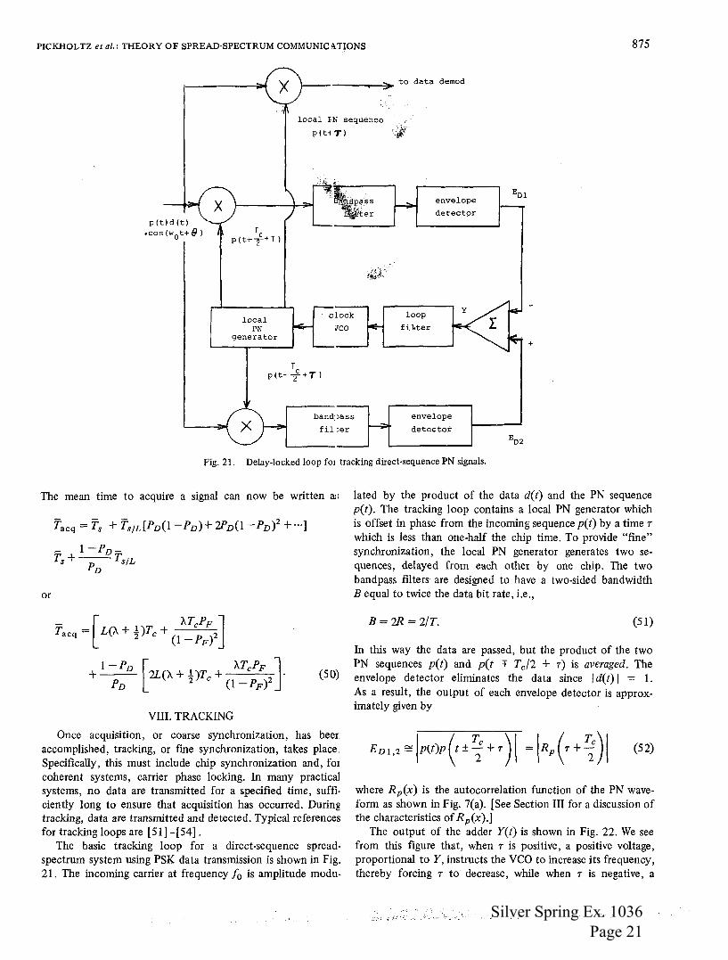
The basic tracking loop for a direct-sequence spreadspectrum system using PSK data transmission is shown in Fig. 21. The incoming carrier at frequency fo is amplitude modu-
lated by the product of the data d(t) and the PN sequence p(t). The tracking loop contains a local PN generator which is offset in phase from the incoming sequence p(t) by a time r which is less than one-half the chip time. To provide "fme" synchronization, the local PN generator generates two sequences, delayed from each other by one chip. The two bandpass fllters are designed to have a two-sided bandwidth B equal to twice the data bit rate, i.e.,
B = 2R = 2/T. (51)
In this way the data are passed, but the product of the two PN sequences p(t) and p(t + Tc/2 + r) is averaged. The envelope detector eliminates the data since I d(t) 1 = 1. As a result, the output of each envelope detector is approximately given by
where Rp(x) is the autocorrelation function of the PN waveform as shown in Fig. 7(a). (See Section III for a discussion of the characteristics of Rp(x ).]
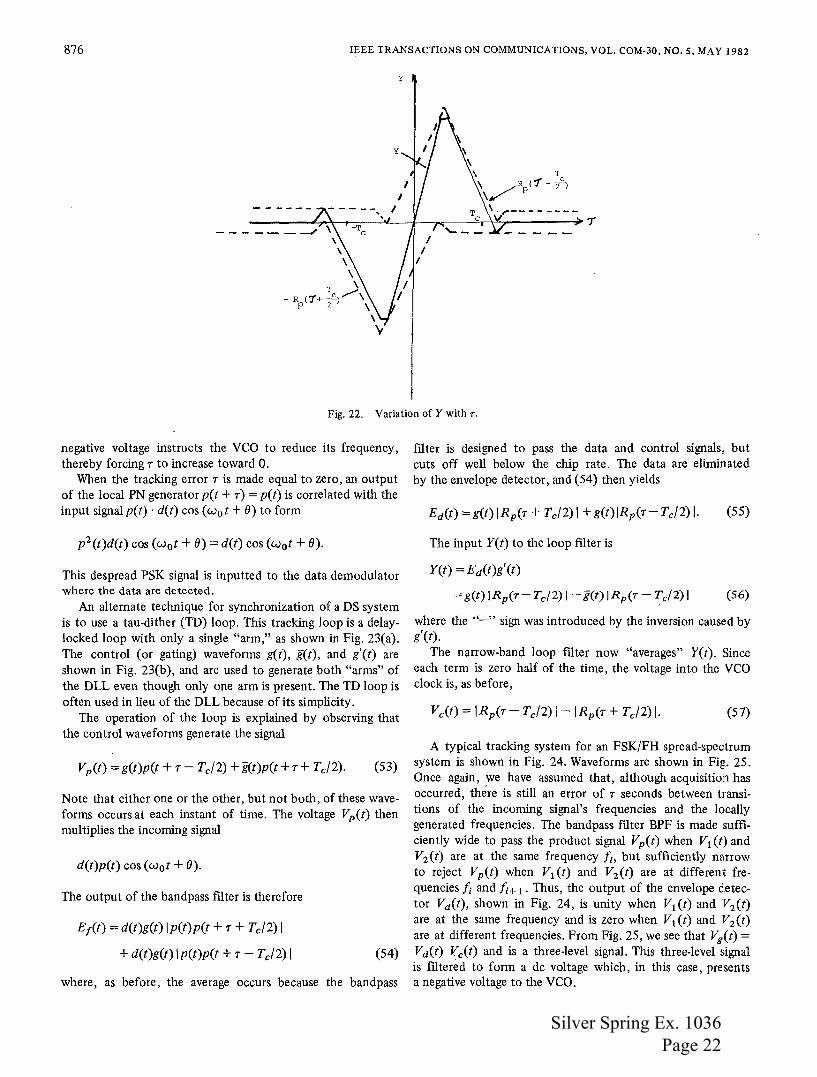
The output of the adder Y(t) is shown in Fig. 22. We see from this figure that, when r is positive, a positive voltage, proportional to Y, instructs the VCO to increase its frequency, thereby forcing r to decrease, while when r is negative, a
Silver Spring Ex. 1036 Page 21
876 IEEE TRANSACTIONS ON COMMUNICATIONS, VOL. COM-30, NO. S, MAY 1982
\ \
\ T \
- R <1+ ~)/\ p 2 \
\ 'v
y
Fig. 22. Variation of Y with r.
negative voltage instructs the VCO to reduce its frequency, thereby forcing 7 to increase toward 0.
When the tracking error 7 is made equal to zero, an output of the local PN generator p(t + 7) = p(t) is correlated with the input signal p(t) · d(t) cos ( w 0 t + 8) to form
p2 (t)d(t) cos (w0 t + 8) = d(t) cos (w 0 t + 8).
This despread PSK signal is inputted to the data demodulator where the data are detected.
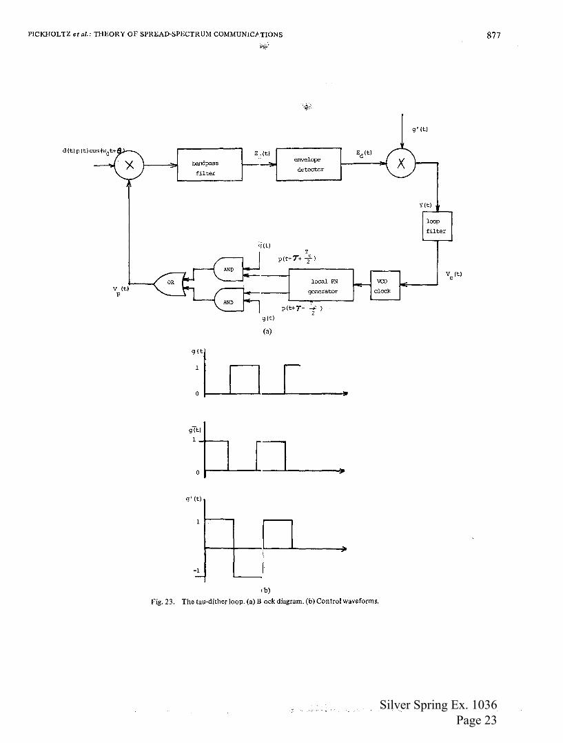
An alternate technique for synchronization of a DS system is to use a tau-dither (TD) loop. This tracking loop is a delaylocked loop with only a single "arm," as shown in Fig. 23(a). The control (or gating) waveforms g(t), g(t), and g'(t) are shown in Fig. 23(b ), and are used to generate both "arms" of the DLL even though only one arm is present. The TD loop is often used in lieu of the DLL because of its simplicity.
The operation of the loop is explained by observing that the control waveforms generate the signal
Vp(t) = g(t)p(t + 7- Tc/2) + g(t)p(t + 7 + Tc/2). (53)
Note that either one or the other, but not both, of these waveforms occursat each instant of time. The voltage Vp(t) then multiplies the incoming signal
d(t)p(t) cos (w0 t + 8).
The output of the bandpass filter is therefore
Er(t) = d(t)g(t) lp(t)p(t + 7 + Tc/2) I
+ d(t)g(t) I p(t)p(t + 7- Tc/2) I (54)
where, as before, the average occurs because the bandpass
filter is designed to pass the data and control signals, but cuts off well below the chip rate. The data are eliminated by the envelope detector, and(54) then yields
The input Y(t) to the loop filter is
Y(t) = Ed(t)g'(t)
= g(t) I Rp(T- Tc/2) I - g(t) I Rp(r- Tc/2) I (56)
where the "-" sign was introduced by the inversion caused by g'(t).
The narrow-band loop filter now "averages" Y(t). Since each term is zero half of the time, the voltage into the VCO clock is, as before,
(57)
A typical tracking system for an FSK/FH spread-spectrum system is shown in Fig. 24. Waveforms are shown in Fig. 25. Once again, we have assumed that, although acquisition has occurred, there is still an error of 7 seconds between transitions of the incoming signal's frequencies and the locally generated frequencies. The bandpass filter BPF is made sufficiently wide to pass the product signal Vp(t) when V1 (t) and V2 (t) are at the same frequency/;, but sufficiently narrow to reject Vp(t) when V1 (t) and V2 (t) are at different frequencies fi and fi+ 1 . Thus, the output of the envelope detector Vd(t), shown in Fig. 24, is unity when V1 (t) and V2 (t) are at the same frequency and is zero when V1 (t) and V2 (t) are at different frequencies. From Fig. 25, we see that Vg(t) = Vd(t) Vc(t) and is a three-level signal. This three-level signal is filtered to form a de voltage which, in this case, presents a negative voltage to the VCO.
Silver Spring Ex. 1036 Page 22
PICKHOLTZ et al.: THEORY OF SPREAD-SPECTRUM COMMUNICP.TIONS
v (t) p
bandpass
filter
g(t)
0
g' (t)
1
-1 -
E.,(t)
<r(t)
g(t)
(a)
envelope
detector
T p(t+T+ 2c)
local PN
generator
p(t+T- f)
rl
ib)
)I
,
vco clock
Fig. 23. The tau-dither loop. (a) B .ock diagram. (b) Control waveforms.
g' (t)
Y(t)
loop
filter
877
Silver Spring Ex. 1036 Page 23

878 IEEE TRANSACTIONS ON COMMUNICATIONS, VOL. COM-30, NO. S, MAY 1982
to data dared
in=ning FH
f0 signal envelope Vg(t)
X BPF ---' ..... detector v
1 (tl 1
2 " local FH v
2(t) wavefonn
Vc(t) LPF
L......_ VF (t)
frequency l.......
PN code clock
synthesizer : generator vro 1-.
Fig. 24. Tracking loop for FH signals.
incoming k-- TH ~ 1/fH ~ signal
I I v1
(tl fo fl f2 f3
local FH signal
V2
(t) fa f1 f2 f3
1
1
71
Vd(t)Q =:J 7 r 7 r t ;;.-
+1
J Vc(t)
I I I F t
-1
+1 q Vg(t) 0 q ,_t
-1~
Vf( t
Fig. 25. Waveforms for tracking an FH signal.
It is readily seen that when V2 (t) has frequency transitions which precede those of the incoming waveform vl (t), the voltage into the VCO will be negative, thereby delaying the transition, while if the local waveform frequency transitions occur after the incoming signal frequency transitions, the voltage into the VCO will be positive, thereby speeding up the transition.
The role of the tracking circuit is to keep the offset time r small. However, even a relatively small r can have a major impact on the probability of error of the received data. Referring to the DS system of Fig. 21, we see that if r is not zero, the input to the data demodulator is p(t)p(t + r)d(t) cos (wot + e) rather than p2(t)d(t) cos (wot + e) = d(t) cos (w 0 t + e). The data demodulator removes the carrier and then averages the remaining signal, which in this case is
p(t)p(t + r)d(t). The result is p(t)p(t + r)d(t). Thus, the amplitude of the data has been reduced by p(t)p(t + r) = Rp(r) .;;;; 1. For example, if r = Tc/10,. that data amplitude is reduced to 90 percent of its value, and the power is reduced to 0.81. Thus, the probability of error in correctly detecting the data is reduced from
to
( ~) Pe(r = Tc/10) = Q 1\j~ ,
Silver Spring Ex. 1036 Page 24

PICKHOLTZ eta/.: THEORY OF SPREAD-SPECTRUM COMMUNIC.~TIONS 879
and at an Ebf'Tio of 9.6 dB, Pe is increased from 10-5 t) w-4_
IX. CONCLUSIONS
This tutorial paper looked at some of the theor.etical issues involved in the design of a spread-spectrum communication system. The topics discussed included the characteristics ofPN sequences, the resulting processing gain when usin:1 either direct-sequence or frequency-hopping antijam considerations, multiple access when using spread spectrum, multipath effects, and acquisition and tracking systems.
No attempt was made to present other than fundamental concepts; indeed, to adequately cover the spread-spectrum system completely is the task for an entire text [55], [56]. Furthermore, to keep this paper reasonably concise, tht: authors chose to ignore both practical system consideration:: such as those encountered when operating at, say, HF, VHF, or UHF, and technology considerations, such as the role o' surface acoustic wave devices and charge-coupled device:: in the design of spread-spectrum systems.
Spread spectrum has for far too long been considered L
technique with very limited applicability. Such is not thf case. In addition to military applications, spread spectrurr is being considered for commercial applications such as mobilf telephone and microwave communications in congested areas
The authors hope that this tutorial will result in mor€ engineers and educators becoming aware of the potential of spread spectrum, the dissemination of this information in the classroom, and the use of spread spectrum (where appropriate) in the design of communication systems.
APPENDIX
ALGEBRAIC PROPERTIES OF LINEAR FEEDBACK SHIFT REGISTER SEQUENCES
In order to fully appreciate the study of shift register sequences, it is desirable to introduce the polynomial representation (or generating function) of a sequence
.oo
C(x) = L Cjxi ~(Co, cl' C2, ·--). i=O
If the sequence is periodic with period L, i.e.,
L-l
C(x)(l-xL) = L Cixi ~R(x) i=O
(Al)
(A2)
with R(x) the (finite) polynomial representation of one period.
Thus, for any periodic sequence of period L,
R(x) C(x)=--·
1-xL' degR(x)<L. (A3)
Next consider the periodic sequence generated by the LFSR recursion. Multiplying each side by x" and summing gives
_oo r 00
l; Cnx" = L ak L Cn- kx" n=O k=l n=o
The left-hand side is the generating function C(x) of the seqvence. The first term on the right is a polynomial of degree <r, call it g(x), which depends only on the initial state of the register C_ 1 , C_ 2, C_ 3, '··, C_,. Thus, the basic equation of the register sequence may be written as
g(x) C(x) = f(x); degg(x) <r (A4)
where f(x) £ 1 - ~k=l akxk is the characteristic polynomial2
(or connection polynomial) of the register. Since C(x) is the generating polynomial of a sequence of period L = 2' - 1, it can be shown froin (A3) and (A4) that f(x) must divide 1 -XL. This is illustrated in the following example.
Example
The three-stage binary maximal length register with f(x) = 1 + x + x 3 has period 7. If the initial contents of the register are c_3 = 1, c_2 = 0, c_l = 0, theng(x) = a3 == 1 and C(x) = 1/(1 + x + x3). Long division (modulo 2) yields
which is the generating function of the periodic sequence
1110100:11101··· . '
and which is precisely the sequence generated by the corresponding recursion
Cn == Cn- 1 + Cn- 3 (mod 2).
Observe that
so that f(x) divides 1 + x 7 • Also, we may write
1 i + x + x 2 + x 4 1 + x + x 2 + x4
C(x) = 1 + x + x3 • 1 + x + x 2 + x 4 1 + x 7
which is in the form of (A3).
2 For binaty sequences, all sums are modulo two and minus is the same as plus. The polynomials defining them have 0, 1 coefficients and are said to be polynomials over a finite field with two elements. A field is a set of elements, and two operations, Say, + and •, which obey the usual rules of arithmetic. A finite field with q elements is d11led a Galois field and is designated as GF(q).
Silver Spring Ex. 1036 Page 25
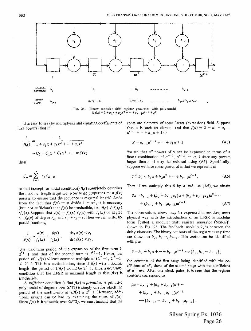
880 IEEE TRANSACTIONS ON COMMUNICATIONS, VOL. COM-30, NO.5, MAY I98:i
initial contents
after clock
Cc2
Fig. 26. Binary modular shift register generator with polynomial fM(X) = 1 +a 1x +a2x2 + ··· +a,_1xr-1 +x'.
It is easy to see (by multiplying and equating coefficients of like powers) that if
1
f(x) := -----------
1 +a1x +a2x2 + ··· +a,x'
then
r
Cn = ~ akCn- k> k=l
so that (except for initial conditions) j(x) completely describes the maximal length sequence. Now what properties must f(x) possess to ensure that the sequence is maximal length? Aside from the fact that f(x) must divide 1 + xL, it is necessary (but not sufficient) that f(x) be irreducible, i.e.,!(x) =F ! 1 (x) ·f2 (x).Suppose that f(x) = f 1(x) h(x) with f 1(x) of degree r1 , f 2 (x) of degree r2 , and r1 + r2 = r. Then we can write, by partial fractions,
1 a{x) ~(x) -=--+--· f(x) f1(x) fi(x)'
deg a(x) <r1
deg~(x) <r2 •
The maximum period of the expansion of the first term is i 1-l and that of the second term is i 2-l. Hence, the period of l/f(x),;; least common multiple of (i1-l, l 2-l) < 2' -3. This is a contradiction, since if f(x) were maximal length, the period of 1/.f(x) would be 2'-1. Thus, a necessary condition that the LFSR is maximal length is that f(x) is irreducible.
A sufficient condition is that f(x) is primitive. A primitive poiynomial of degree r over GF(2) is simply one for which the period of the coefficients of 1/.f(x) is 2'-1. However, additional insight can be had by examining the roots of f(x). Since f(x) is irreducible over GF(2), we must imagine that the
roots are elements of some larger (extension) field. Suppose that a is such an element and that f(a) = 0 = a' + a,_ 1
a'- 1 + ··· + a1 a+ 1 or
(AS)
We see that all powers of a can be expressed in terms of a linear combination of a'- 1
, a'-2 , ... , a, 1 since any powers larger than r- 1 may be reduced using (AS). Specifieally, suppose we have some power of a that we represent as
(A6)
Then if we multiply this ~ by a and use (AS), we obtain
~a= br-1 + (b 0 + b,_tada + (bt + b,_ 1a2 )a2 + ···
(A7)
The observations above may be expressed in another, :more physical way with the introduction of an LFSR in modular form [called a modular shift register generator (MSRG)] shown in Fig. 26. The feedback, modulo 2, is between the delay elements. The binary contents of the register at any time are shown as b0 , b, ···, b,_ 1 . This vector can be identified with~ as
the contents of the first stage being identified with the co· efficient of a0 , those of the second stage with the coefficient of a 1
, etc. After one clock pulse, it is seen that the register contents correspond to
~a= br-1 + (b 0 + b,_ t)a + ···
+ (br-2 + b,_lar- t)ar-l
Silver Spring Ex. 1036 Page 26

PICKHOLTZ eta/.: THEORY OF SPREAD-SPECTRUM COMMUNICA.TIONS 881
Thus, the MSRG is an a-multiplier. Now if a0, a, a2
, a3, ·' ,
aL-1 , L = 2r -1 are all distinct, we call a a primitive elemer t of GF(2r). The register in Fig. 26 cycles through all statEs (starting in any nonzero state), and hence generates a maximal length sequence. Thus, another way of describing that the polynomial fM(x) is primitive (or maximal length) is that t has a primitive element in GF(2r) as a root.
There is an intimate relationship between the MSRG shown in Fig. 26 and the SSRG shown in Fig. 4. From Fig. 2 5 it is easily seen that the output sequence Cn satisfies the recursion
r- 1
Cn = ~ akCn- r+k· k=O
Multiplying both sides by xn and summing yields
oo r....:..... 1 oo
C(x) ~ ~ Cnx" = ~ ak ~ Cn-r+kxn n=- 00 k=O n=O
or
(AS)
(A9)
TABLE I THE NUMBER OF MAXIMAL LENGTH LINEAR SRG SEQUENCES
OF DEGREE r = ;>..(r) = </>(2T- 1)/r
2r-1
15
31
63
127 18
255 16
511 48
10 1 ,023 60
11 2,047 176
12 4,095 144
13 8,191 630
14 16,383 756
15 32.767 1,800
16 65,535 2,048
17 131,071 7,710
18 262,143 8,064
19 524,287 27,594
20 1,048,575 24,000
21 2,097,151 87,672
22 4,194,303 120,032
r- 1
C(x) = gM(x) + x' ~ akx- kC(x). k=O
do not list all the primitive polynomials, algorithms exist [7] which allow one to generate all primitive polynomials of a
(A10) given degree if one of them is known. The number :\(r) of primitive polynomials of degree r is [ 4]
gM(x) is the first term on the right-hand side of (A9) and is a polynomial of degree < r which depends on the initial state. Then we have
(A111
where
(recall that in GF(2), minus is the same as plus) is the char· actedstic (or connection) polynomial of the MSRG. Since thE sequence Cn [of coefficients of C(x)] whenfM(x) is primitivE depends only on fM(x) (discounting phase), the relationship between the SSRG and the MSRG which generates the samf:. sequence is
fM(x) is called the reciprocal polynomial of f(x) and is ob tained from f(x) by reversing the order of the coefficients
There are several good tables of irreducible and primitive polynomials available [2], [5], [6], and although the table~
rp(2r- 1) :\(r)=---
r (A13)
where rf>(m) is the number of integers less than. m which are relatively prime to m (Euler totient function). The growth of this number with r is shown in Table I.
The algebra of LFSR's is useful in constructing codes with uniformly low cross correlation known as Gold codes. The underlying principle of these codes is based on the following theorem [15].
If / 1 (x) is the minimal polynomial of the primitive element a E GF(2r) and ft(x) is the minimal polynomial of at, where both/1 (x) andft(x) are of degree rand
r+ 1 2-2- + 1, r odd
t= r+2
2-2- + 1, r even,
then the product f(x) ~ / 1 (x )fr(x) determines an LFSR which generates 2r + 1 different sequences (corresponding to the 2r + 1 states in distinct cycles) of period 2r - 1, and such that for any pair c' and c"'
L IRc'c"(r) I< t.
., }1i;. ';t ' • '.,' .
Silver Spring Ex. 1036 Page 27

882 IEEE TRANSACTIONS ON COMMUNICATIONS, VOL. COM·30, NO.5, MAY 1982
1 X
1 X
2 X
2 X
(a)
(b)
3 X
4 X
4 X
Fig. 27. Two implementations of LFSR which generate Gold codes of length 25 - 1 = 3 i with maximum cross correlation t = 9. (a) LFSR with f(x) = 1 + x + x3 + x9 + x10. (b) LFSR which generates sequences corresponding tof(x) = (1 +x2 + xS)·(l +x2 +x4 +x5) = 1 +x +x3 +x9 +x10.
Futhermore, Rc'c"(r) is only a three-valued function for imy integer r.
A minimal polynomial of ex is simply the smallest degree moniC3 polynomial for which ex is a toot. With the help of a table of primitive polynomials, we can identify niihimal polynomials of powers of ex and easily construct Gold codes: For example, if r = 5 and t = 23 + 1 = 9, using [2] we find that f 1(x) = 1 + x 2 + x 5 and[9(x) = 1 + x 2 + x 4 + x 5
. Then f(x) := 1 + x + x3 + x 9 + x1 0 • The two ways to represent this LFSR (in MSRG, form) are shown in Fig. 27. Fig. 27(a) Shows one long nonmaximallength register of degree 10 which gerie~ates sequences of period 25 . .:_ 1 ;, 31. Since there are ~ 1 0 - 1 possible norizero initial states, the riumber of initial states that result in distinctcydesis(210
- 1)/(25- 1) = 25 +
1 = 33. Each of these initial states specifies a different Gold cOde of length 31. Fig. 27(b) shows how the same result can be obtained by adding the outputs of· the two MLFSR's of degree 5 together modulo two. This follows simply from the observation that the sequence(s) generated by f(x) are just the coefficients in the expansion of 1/f(x) = 1/f1(x)·f9 (x). By using partial fractions, one can see that the resulting coefficients are the (modulo two) sum of the coefficients of like powets in the expansion of 1/[1 (x) and 1/f9 (x). Naturally, the sequence resulting will depend on the relative phases of the two degree-S registers. As before, there are (2 1 0 - 1)/(25 -I)=
3 A monic polynomial is one whose coefficient of its highest power is unity.
25 + 1 = 33 relative phases which result in 33 different sequences satisfying the cross-correlation bound given by the theorem.
C(x)
Cn Cn'or Cn" D d(t) t,
fc FH Gp J(t)
GLOSSARY OF SYMBOLS
{0, 1} feedback taps for LFSR. One-sided bandwidth (Hz) for data signal(s). Orte-sided bandwidth (Hz) of baseband spread-spectrum signal. Generating fmiction of Cn; C(x) = L;;'=o Cnxn. {0, 1} LFSR sequence. { 1, -1} LFSR sequence. Dimensionality of underlying signal space. Data sequence waveform. Initial offset, in chips, of incoming signal and locally generated code. Direct sequence. Energy /i11formation bit. Jammer energy over the correlation interval. Energy /symbol. Characteristic (connection) polynomial of an LFSR, f(x) = 1 + a1 x + ··· + a;-_ 1 x r--l + xr. Chip rate; Tc = 1/fc· Frequency hopping. Processing gain. Jammer signal waveform.
Silver Spring Ex. 1036 Page 28

PICKHOLTZ etal.: THEORY OF SPREAD-SPECTRUM COMMUNICATIONS 883
K
L = 2r -1
L A.
A.(r)
TloJ nw(t) p(t) Pv Pe Pp PJ PN Ps PN r r(t) R Rp(r) Rc'c"(r)
p(r)
p(r) S(t) Sp(J)
SNR SJR T Tc
TH
v
Number of frequencies jammed by partia.· band jammer. Period ofPN sequence. Implementation losses. Number of chips examined during eachsearc1 in the process of acquisition. . Number of binary maximal length PN'·,c~od~ s of degree r (length L = 2r- 1). Signal alphabet size. Jamming margin. Number of chips/bit or number of dimensior.s of spread signal space. Number of frequencies in FH. Number of chips in uncertainty region itt start of acquisition. Number of users in CDMA system. One-sided white noise power spectral density (W/Hz). PJ/2fc =power density of jammer. Additive white Gaussian noise (AWGN). Spreading sequence waveform. Probability of detection. Probability of error. Probability of false alarm. Jammer power. Noise power. Signal power. Pseudonoise sequence. Number of stages of shift register. Received waveform. Data rate (bits/s). Autocorrelation function. Cross-correlation function of two (periodic) ± 1 sequences Cn', Cn': (1/T) fb p(t) p(t - r) dt (partial correlation function). (1/T) f{ p(t) p(t -r)dt. Transmitted signal waveform. Power spectral density of spreading sequence waveform [also denoted Sss(j)]. Signal-to-noise power ratio. Signal-to-jammer power ratio. Signal or symbol duration. Chip duration. Time to hop one frequency; 1/TH =hopping rate. Correlator output voltage.
ACKNOWLEDGMENT
The authors wish to thank the anonymous reviewers fer their constructive suggestions in the final preparation of th: s paper.
REFERENCES
[I] R. A. Scholtz, "The origins of spread-spectrum communications, ·• this issue, pp. 822-854.
[2] W. W. Peterson and E. J. Weldon, Jr., Error Correcting Code:·, 2nd ed. Cambridge, MA: M.I.T. Press, 1972.
''P.tri. [3 ';1:'·M. Wozencraft and I. M. Jacobs, Principles of Communication
ilgineering. New York: Wiley, 1965. [4] <' • W. Golomb, Shift Register Sequences. San Francisco, CA:
Holden Day, 1967. [5] R. W. Marsh, Table of Irreducible Polynomials over GF(2)
Through Degree 19. Washington, DC: NSA, 1957. [6] W. Stahnke, "Primitive binary polynomials," Math. Comput.,
vol. 27, pp. 977-980, Oct. 1973. [7] E. R. Berlekamp, Algebraic Coding Theory. New York: Mc
Graw-Hill, 1968. [8] J. L. Massey, "Shift-register synthesis and BCH decoding," IEEE
Trans. Inform. Theory, vol. IT-15, pp. 122-127, Jan. 1969. [9] N. G. deBruijn, "A combinatorial problem," in Koninklijke
Nederlands Akademie Van Wetenschappen Proc., 1946, pp. 758-<764.
[IO~k'E. J. Groth, "Generation of binary sequences with controllable ·~ complexity," IEEE Trans. Inform. Theory, vol. IT-17, pp. 288-
296, May 1971. [II] E. L. Key, "An analysis of the structure and complexity of
nonlinear binary sequence generators," IEEE Trans. Inform. Theory, vol. IT-22, pp. 732-736, Nov. 1976.
[12] H. Beker, "Multiplexed shift register sequences," presented at CRYPTO '81 Workshop, Santa Barbara, CA, 1981.
(13] J. L. Massey and J. J. Uhran, "Sub-baud coding," in Proc. 13th Annu. Allerton Conf. Circuit and Syst. Theory, Monticello, IL, Oct. 1975, pp. 539-547.
[14] J. H. Lindholm, "An analysis of the pseudo randomness properties of the subsequences of long m-sequences," IEEE Trans. Inform. Theory, vol. IT-14, 1968.
[15] R. Gold, "Optimal binary sequences for spread spectrum multiplexing," IEEE Trans.lnform. Theory, vol. IT-13, pp. 619-621, 1967.
[16] D. V. Sarwate and M. B. Pursley, "Cross correlation properties of pseudo-random and related sequences," Proc. IEEE, vol. 68, pp. 598-619, May 1980.
[17] A. Lempel, M. Cohn, and W. L. Eastman, "A new class of balanced binary sequences with optimal autocorrelation properties," IBM Res. Rep. RC 5632, Sept. 1975.
[18] A. G. Konheim, Cryptography, A Primer. New York: Wiley, 1981. .
[19] D. L. Schilling, L. B. Milstein, R. L. Pickholtz, and R. Brown, "Optimization of the processing gain of an M-ary direct sequence spread spectrum communication system," IEEE Trans. Commun., vol. COM-28, pp. 1389-1398, Aug. 1980.
[20] L. B. Milstein, S. Davidovici, and D. L. Schilling, "The effect of multiple-tone interfering signals on a direct sequence spread spectrum communication system," IEEE Trans. Commun., vol. COM-30, pp. 436-446, Mar. 1982.
[21] S. W. Houston, "Tone and noise jamming performance of a spread spectrum M-ary FSK and 2, 4-ary DPSK waveforms," in Proc. Nat. Aerosp. Electron. Conf., June 1975, pp. 51-58.
[22] G. K. Huth, "Optimization of coded spread spectrum systems performance," IEEE Trans. Commun., vol. COM-25, pp. 763-770, Aug. 1977.
[23] R. H. Pettit, "A susceptibility analysis of frequency hopped M-ary NCPSK-Partial~band noise on CW tone jamming," presented at theSymp. Syst. Theory, May 1979.
[24] L. B. Milstein, R. L. Pickholtz, D. L. Schilling, "Optimization of the processing gain of an FSK-FH system," IEEE Trans. Commun., vol. COM-28, pp. 1062-1079, July 1980.
[25] M. K. Simon and A. Polydoros, "Coherent detection offrequencyhopped quadrature modulations in the presence of jamming-Part I: QPSK and QASK; Part II: QPR class I modulation," IEEE Trans. Commun., vol. COM-29, pp. 1644-1668, Nov. 1981.
[26] A. J. Viterbi and I. M. Jacobs, "Advances in coding and modulation for noncoherent channels affected by fading, partial band, and multiple access interference," in Advances in Communication Systems, vol. 4. New York: Academic, 1975.
[27] J. M. Aein and R. D. Turner, "Effect of co-channel interference on CPSK carriers," IEEE Trans. Commun., vol. COM-21, pp. 783-790, July 1973.
[28] R. H. Pettit, "Error probability for NCFSK with linear FM jamming," IEEE Trans. Aerosp. Electron. Syst., vol. AES-8, pp. 609-614, Sept. 1972.
[29] A. J. Viterbi, "Spread spectrum communications-Myths and realities." IEEE Commun. Mag., pp. 11-18, May 1979.
[30] D. J. Torrieri, Principles of Military Communication Systems. Dedham, MA: Artech House, 1981.
Silver Spring Ex. 1036 Page 29

884 IEEE TRANSACTIONS ON COMMUNICATIONS, VOL. COM-30, NO.5, MAY 1982
[31] M. B. Pursley, "Performance evaluation for phase-coded spread spectrum multiple-access communication-Part I: System analysis," IEEE Trans. Commun., vol. COM-25, pp. 795-799, Aug. 1977.
[32] K. Yao, "Error probability of asynchronous spread-spectrum multiple access communication systems," IEEE Trans. Commun., vol. COM-25, pp. 803-809, Aug. 1977.
[33] C. L. Weber, G. K. Huth, and B. H. Batson, "Performance considerations of code division multiple access systems," IEEE Trans. Veh. Techno/., vol. VT-30, pp. 3-10, Feb. 1981.
[34] M. B. Pursley and D. V. Sarwate, "Performance evaluation for phase-coded spread spectrum multiple-access communicationPart II. Code sequence analysis," IEEE Trans. Commun., vol. COM-25, pp. 800-803, Aug. 1977.
[35] M. B. Pursley and H. F. A. Roefs, "Numerical evaluation of correlation parameters for optimal phases of binary shift-register sequences," IEEE Trans. Commun., vol. COM-25, pp. 1597-1604, Aug. 1977.
[36] G. Solomon, "Optimal frequency hopping sequences for multiple access," in Proc. 1973 Symp. Spread Spectrum Commun., vol. I, AD915852, pp. 33-35.
[37] D. V. Sarwate and M. B. Pursley, "Hopping patterns for frequency-hopped multiple-access communication," in Proc. 1978 IEEE Int. Conf. Commun., vol. I, pp. 7.4.1-7.4.3.
[38] P. S. Henry, "Spectrum efficiency of a frequency-hopped-DPSK spread spectrum mobile radio system," IEEE Trans. Veh. Techno/., vol. VT-28, pp. 327-329, Nov. 1979.
[39] 0. C. Yue, "Hard-limited versus linear combining for frequencyhopping multiple-access systems in a Rayleigh fading environment," IEEE Trans. Veh. Techno/., vol. VT-30, pp. 10-14, Feb. 1981.
[40] R. W. Nettleton and G. R. Cooper, "Performance of a frequencyhopped differentially modulated spread-spectrum receiver in a Rayleigh fading channel," IEEE Trans. Veh. Techno/., vol. VT-30, pp. 14-29, Feb. 1981.
[41] D. E. Borth and M. B. Pursley, "Analysis of direct-sequence spread-spectrum multiple-access communication over Rician fading channels," IEEE Trans. Commun., vol. COM-27, pp. 1566-1577, Oct. 1979.
[42] E. A. Geraniotis and M. B. Pursley, "Error probability bounds for slow frequency-: ...,pped spread-spectrum multiple access communications over fading channels," in Proc. /981 Int. Conf. Commun.
[43] L. B. Milstein and D. L. Schilling, "Performance of a spread spectrum communication system operating over a frequencyselective fading channel in the presence of tone interference,'' IEEE Trans. Commun., vol. COM-30, pp. 240-247, Jan. 1982.
[44] --, "The effect of frequency selective fading on a noncoherent FH-FSK system operating with partial-band interference," this issue, pp. 904-912.
[45] J. M. Aein and R. L. Pickholtz, "A simple unified phasor analysis for PN multiple access to limiting repeaters,'' this issue, pp. 1018-1026.
[46] R. B. Ward, "Acquisition of pseudonoise signals by sequential estimation," IEEE Trans. Commun. Techno/., vol. COM-13, pp. 474-483, Dec. 1965.
[47] R. B. Ward and K. P. Yiu, "Acquisition ofpseudonoise signals by recursion-aided sequential estimation," IEEE Trans. Commun., vol. COM-25, pp. 784-794, Aug. 1977.
[48] P. M. Hopkins, "A unified analysi> of pseudonoise synchronization by envelope correlation," IEEE Trans. Commun., vol. COM-25, pp. 770-778, Aug. 1977.
[49] J. K. Holmes and C. C. Chen, "Acquisition time performance of PN spread-spectrum systems," IEEE Trans. Commun., vol. COM-25, pp. 778-783, Aug. 1977.
[50] S. S. Rappaport, "On practical setting of detection threshold.s," Proc. IEEE, vol. 57, pp. 1420-1421, Aug. 1969.
[51] J. J. Spilker, Jr., "Delay-lock tracking of binary signals," IEEE Trans. Space Electron. Telem., vol. SET-9, pp. 1-8, Mar. 1963.
[52] P. T. Nielson, "On the acquisition behavior of delay lock loops," IEEE Trans. Aerosp. Electron. Syst., vol. AES-12, pp. 415-523, July 1976.
[53] --, "On the acquisition behavior of delay lock loops," IEEE Trans. Aerosp. Electron. Syst., vol. AES-11, pp. 415-417, May 1975.
[54] H. P. Hartman, "Analysis of the dithering loop for PN c:ode tracking," IEEE Trans. Aerosp. Electron. Syst., vol. AES-10, pp. 2-9, Jan. 1974.
[55] R. C. Dixon, Spread Spectrum Systems. New York: Wiley, 1976. [56] J. K. Holmes, Coherent Spread Spectrum Systems. New York:
Wiley, 1982.
* Raymond L. Pickholtz (S'54-A'55-M'60-SM'77-F'82) received the B.E.E. and M.S.E.E. degrees from the City College of New York, New York, NY, and the Ph.D. degree from the Polytechnic Institute of Brooklyn, Brooklyn, NY.
He is a Professor and was Chairman of the Department of Electrical Engineering and Computer Science, George Washington University, Washington, DC. He was a Research Engine,er at RCA Laboratories and at ITT Laboratories for a
period of ten years, working on problems ranging from color television to secure communications and guidance before returning to academia. He was an Associate Professor at the Polytechnic Institute of Brooklyn until 1972 when he joined the faculty at George Washington University. He taught part-time at New York University, New York, and in the Department of Physics, Brooklyn College, Brooklyn. He was a Visiting Professor at the University of Quebec, Quebec, P.Q., Canada. He has been an active consultant in communications to industry and government for many years and has lectured extensivley in this country, Canada,. Europe, and South America on various aspects of communications. He is President of Telecommunications Associates, a small consulting and research firm.
Dr. Pickholtz has been very active in the IEEE and in the Communications Society (ComSoc) in particular. He was the first Editor for Computer Communication of the IEEE TRANSACTIONS ON COMMUNICATIONS. He organized the Technical Committee on Computer Communication of ComSoc. He was Guest Editor of the Special TRANSACTIONS Issue on Computer Communications. He was General Chairman of the Third Data Networks Symposium and of the Workshop on Data Networks. In addition, he was Chairman of the New York Chapter of the Information Theory Group and has also contributed his efforts to the Computer Society.
* Donald L. Schilling (S'56-M'58-SM'69-F'75), for a photograph and biography, see this issue, p. 821.
* Laurence B. Milstein (S'66-M'68-SM'77), for a photograph and biography, see this issue, p. 820.
Silver Spring Ex. 1036 Page 30