Embed Size (px)
Citation preview

Machine Information ..............................................................2
Contacting Intec ......................................................................3
Introduction ............................................................................4
Specifications ..........................................................................5
Overview ..................................................................................6
How the System Works Together ..........................................9
Safety First ............................................................................11
Set-Up and Operation ..........................................................12
Operational Guidelines ........................................................15
Sidewalls & Insulation Material ..........................................16
Generators and Extension Cords ........................................18
Maintenance ..........................................................................19
Troubleshooting ....................................................................25
Mechanical Drawings ..........................................................29
Electrical Drawings ..............................................................35
Claims, Damage or Loss ......................................................48
Returns ..................................................................................50
Receiving Replacement Parts ..............................................51
Warranty ................................................................................52
Insulation Terms and Values ................................................53
THE FORCE/2Table of Contents
CO
NTEN
TS
1D200-0200-00 KL REV 10/04

MACHIN
EIN
FO
RM
ATIO
N
2

Phone support:
Available Monday - Friday, excluding holidays. In the United States and Canada, call
(800) 666-1611, 7:00 A.M. to 5:00 P.M. Mountain Time. Ask for technical support
and one of our technicians will be glad to help you.
On-site/off-site repair support:
Available Monday to Friday, excluding holidays. In the United States and Canada,
call (800) 666-1611, 7:00 A.M. to 5:00 P.M. Mountain time. For the latest
repair/service centers across the United States visit our web site,
www.inteccorp.com and go to service centers. All service centers are independently
owned and operated and are not part of Intec. Consult the nearest service center
for the hours of operation and lead time for repair.
Website support:
Visit our web site 24/7 at www.inteccorp.com and go to the specific model
your wanting information on, then go to the technical bulletins section. The
technical section of the web site is constantly being updated with new information
and technical documents. If you cannot find what you are looking for please contact
us Monday - Friday, excluding holidays, in the United States and Canada, call (800)
666-1611, 7:00 A.M. to 5:00 P.M. Mountain Time. Ask for technical support and one
of our technicians will be glad to help you.
Contact Information:
3771 Monarch Street Frederick, CO 80530Ph: 1-303-833-6644
1-800-666-1611Fax: 1-303-833-6650E-mail: [email protected]
CO
NTACTIN
GIN
TEC
3
THE FORCE/2Contacting Intec

Your FORCE/2 insulation blowing machine, the product of years of laboratory
and field testing, offers both the contractor and the homeowner exceptional
performance, total reliability, and ease of use.
It is designed and built to blow-in more than a ton of material per hour. No other
machine in its class can match the performance of the FORCE/2.
Because no insulation goes through the blower, the FORCE/2 is a virtual
workhorse, requiring only minimal maintenance. The direct drive feature also
means there are no chains for you to adjust or replace, ever.
Following the instructions in this manual,
setting up and operating the FORCE/2 on
the jobsite will be uncomplicated, quick,
safe, and easy. Once your work is finished,
end-of-the-day clean up is equally efficient.
Exceptional performance. Total reliability.
Ease of use. Those are the reasons why the
FORCE/2 is your best choice.
Rex DeitesfieldPresident
THE Force/2Insulation Blowing Machine
IN
TRO
DUCTIO
N
4

THE FORCE/2Specifications
SPECIFICATIO
NS
Height 45" without wheels501⁄2" with wheels
Width 32"
Weight 283 lbs. without wheels302 lbs. with wheels
Hopper Capacity 50 lbs.
Hose Size 3"
Blower, 2-stage 105 CFM, 3.6 PSI (AVG) 11.5 amps116 CFM, 4.5 PSI (AVG) 12.5 amps (Optional)
Agitator Motor 1-1⁄2 hp - 14.5 or 17.2 amps 115 VAC2 hp - 21 AMPS 115 VAC (Optional)
Gear Box Custom, direct drive
Airlock 8" x 10" opening, steel, 6-vane,cast urethane seals
Electric 115/220 VAC single phase
Agitator 6-blade
Warranty One year limited;
90 days limited on electric,
blower and airlock system
Specifications are subject to change without notice.
5

THE FORCE/2Overview
OVERVIEW
6
Main PanelSwitches
Agitator MotorCircuit Breaker
Flange Receptacle(Power Cord)
Variable SpeedBypass Switch
Remote SwitchBlower/ Agitator
Remote ControlReceptacleVariable
Speed Control
FiberglassBale Breaker (Optional)
Agitator
THE FORCE/2Overview, Cont.
OVERVIEW
THREE SUBSYSTEMS MAKE UP YOUR FORCE/2:
1. THE AGITATOR AND AIRLOCK. Your FORCE/2 runs on a 1-1⁄2 or 2 horsepower motor driving an enclosed gearbox. The gearbox drives both
the agitator and airlock components at a constant speed.
2. THE BLOWER MOTOR. Your FORCE/2 is equipped with either
a 105 or 116 CFM two-stage blower motor to push the material through the
hose and into the attic with optimum pressure and output. The blower is
connected to the air intake port of the airlock by a plastic hose.
3. ELECTRICAL COMPONENTS. Your FORCE/2 requires two
dedicated 20 amp grounded outlets. A circuit (outlet) rated lower
than 20 AMPS may cause premature tripping at the power source.
Always disconnect the power
cords before beginning any
maintenance. And as with all
electrical systems, never attempt
to operate your FORCE/2 with
either the operator or the
machine standing in water.
SYSTEM COMPONENTS. (See next page for drawings.)
A. Hopper: Upper component of the FORCE/2 where insulation
is loaded.
B. Base: Lower component of the FORCE/2 houses power
components, agitator motor, blower, gearbox, airlock and electrical
system.
C. Slide gate: Regulates the amount of material entering the airlock.
D. Electrical: Operates the on/off function of both the blower and
agitator motors.
E. Remote: Allows the control of the on/off function of both the
blower and agitator motors via a 100" control cable.
7

THE FORCE/2Overview, Cont.
OVERVIEW
8
Example only see page 35 for specific electrical systems.
Remote Cord

THE FORCE/2How the System Works Together
AGITATOR: Conditions the insulation material to an optimum configu-
ration, then sweeps the material into the airlock for distribution through the
hose.
AGITATOR MOTOR: Drives the gearbox. No maintenance is required.
Produces 1-1⁄2 HP @ 14.5 or 17.2 amps, 115 VAC. Optional motor 2 HP @ 21
amps, 115 VAC.
AIRLOCK: Moves the conditioned insulation material from the agitator into
the air flow from the blower. Airlock seals must be inspected regularly and kept
in good working order for the FORCE/2 to operate efficiently. We recommend
changing the airlock seals every 300 hours, 200,000 pounds of insulation or once
a year, whichever comes first.
BLOWER: Creates the airflow which propels the material from the airlock
into the hose for distribution. No insulation material passes through the blower.
The standard blower moves 105 CFM drawing 11.5 amps, 115 VAC or the
optional 116 CFM blower draws 12.5 amps at 115 VAC. See the maintenance
section for required service.
GEARBOX: Operates both the airlock and agitation system, the gearbox
requires periodic maintenance, including changing the oil at least once a year. See
the maintenance section for more details about changing the gearbox oil. If you
are working in cold weather, changing to Mobil 1 or 5W-30 high performance
synthetic oil will aid in cold weather start-ups. In addition, inspect the gearbox
and airlock alignment regularly. Alignment must be perpendicular to each other,
preventing excess wear on the airlock and gearbox shaft connection.
HO
WTHE
SYSTEM
WO
RKS
TO
GETHER
9

THE FORCE/2How the System Works Together, Cont.
REMOTE CONTROL:
Permanently attached to the main panel, the remote
control cord allows the operator to control the machine’s
on/off function from the attic. Both the agitator and the
blower can be operated independently by the remote
control. The blower speed control is built into the remote
cord to enable the operator to decrease or increase blower
pressure and air volume.
DETACHABLE REMOTE
The remote cord must be attached at all times in order
for the machine to operate. To connect, locate the keyed
positions on both the receptacle (Electrical panel) and
connector on remote cord. Insert connector into
receptacle and turn clockwise until it clicks in. To lock
remote cord into receptacle, turn blue outer ring on
remote cord connector and turn clockwise until it stops.
HO
WTHE
SYSTEM
WO
RKS
TO
GETHER
10
Remote Controlwith VS Control
Remote Controlwith Disconnect
Align, Push in and Twist Turn outer Ring

THE FORCE/2Safety First
SAFETY
FIRST
11
Never put your hands into the hopper while the machine is running.
Keep tools and other foreign objects out of the hopper. Clean all material out of thehopper and the hose when your job is complete.
Never leave your machine unattended while it is running. Turn “off ” and disconnectpower before taking a break.
Never operate your machine if it or the operator is standing in water. Serious injurymay result.
When working with insulation, always wear a long sleeve shirt, gloves, a hat, gogglesor safety glasses for eye protection and a 3M brand #8710 nose/mouth filter (orequivalent) for respiratory protection.
ACCESSORIES YOU NEED TO WEAR...
SAFETYGLASSESOR GOGGLES
CAP
LONG-SLEEVEDSHIRT
GLOVES

THE FORCE/2Set-Up and Operation
12
ELECTRICAL CONNECTIONS: Before connecting the machine to
electrical power, make sure all switches are in the "off " position. Connect
both supplied extension cords to dedicated 115V 20 amp grounded outlets. In
the home, refrigerator or freezer outlets usually fit the amperage requirements.
If necessary, these appliances can be temporarily unplugged, enabling the
FORCE/2 to use the outlet. Disconnecting
these appliances for the short time needed to
operate the FORCE/2 will not cause spoilage.
Remember to reconnect any unplugged
appliance after the job is finished. If your job
requires additional extension cords, make sure you use only a 10/3
cord for a 50 foot run or 8/3 cord for a 100 foot extension.
STARTING:
Operation from the Attic: To use the remote control feature for attic
operation, the switches on the main electrical panel must be in the "on"
position. Control the machine using the rocker switch on the remote cord.
Operation from the Ground: To operate the FORCE/2 from the
ground, the rocker switch on the remote control must be in the “on” position.
Operate the blower and agitator from the main electrical panel toggle
switches. Note: In cold weather, your machine is more difficult to start. If
possible, store your FORCE/2 in a warm area over-night before starting this
helps ensure the lubricant (oil) is warm,
enabling the bearings and gearbox to turn
freely.
SET-UP
AN
DO
PERATIO
N

THE FORCE/2Set-Up and Operation, Cont.
SET-UP
AN
DO
PERATIO
N
13
HOSE SETUP, ATTIC:
Cellulose: For normal attic applications, use
a minimum of 100 feet of 3 inch hose on
your job. Longer hose length decreases both
capacity and material throw. Using 200 feet of
hose, capacity and throw will be reduced by
approximately 30%. If you must use a hose
longer than 150 feet, reduce the hose size to
2-1⁄2 inch diameter for the last 50'.
Fiberglass: Use a minimum of 150 feet of hose. Use 100 feet of 3” hose and a
50 foot section of 2-1/2” hose using a 3 x 2-1/2” steel hose reducer. This hose
configuration aids in the opening of the fiber and increases the throw of the
material.
Example of Hose Connections:
HOPPER SAFETY: Your safety is the most important consideration
whenever you are using any machine. Following the instructions in this manual
along with good common sense, should allow you to complete your job in a safe
and efficient manner. First, before loading your FORCE/2, follow all safety
considerations provided by the manufacturer of the insulation material you are
using, including wearing protective masks or respirators. Never wear loose clothing
or other items while running this machine. Failure to follow safety precautions may
result in permanent injury.
Any time you overload the hopper or place objects other than
insulation material into the hopper, you are risking personal
injury or equipment breakdown.

THE FORCE/2Set-Up and Operation, Cont.
14
LOADING THE HOPPER: Machine may be “on or off ” while loading.
Cellulose, place the bag of insulation material on the hopper. Use a knife to
open the bag so that the material falls into the hopper. Your FORCE/2 is designed
to self-feed. Fiberglass, place the bag on the side of the hopper. Cut the bag in
thirds and dispense one third of the contents gradually until the agitator breaks up
and conditions the material. Load the remainder of the material according to the
distribution rate. Empty no more than 1⁄3 bag at a time into the hopper, waiting
until at least 1⁄4 of the material has been used before adding additional insulation.
Forcing insulation material will cause overloading, electrical
failure or possible machine damage.
If the agitator stops or the circuit breaker on the electrical panel trips, unplug the
machine from electrical power. Remove the cause of the jam from the hopper. You
may have to empty all the insulation material to locate and remove the jam. After
clearing, reset the circuit breaker, reconnect power and continue normal operation.
See page 22 for more information on unjamming.
SET-UP
AN
DO
PERATIO
N
Fiberglass Insulation Only: Cut as shown and break bag into three sections

THE FORCE/2Operational Guidelines
OPERATIO
NAL
GUIDELIN
ES
BLOWING SIDEWALLS, CELLULOSE:
When blowing sidewalls, use the following settings and recommendations as
guidelines. Settings may change from job to job, material to material, or nozzle
to nozzle. Hose length and humidity may affect your results.
Two hole method, standard wall construction: 2" x 4" x 16" on center.
Hole size Slide gate opening Air Setting
2" 2" 100%1" 11⁄2" 100%5/8" 1" 100%
Keeping the material level consistent in the hopper will aid in achieving good
sidewall densities. A gradual transition in hose size will aid in the material flow
and help eliminate clogging. At the machine, start with 50' of 3" hose, connect
50' of 2-1⁄2" next and then connect 50' of 2". Use hose reducers and clamps to
connect the hose making sure all connections are tight see page 13 for
examples of hose set-up. If clogging or less than satisfactory compaction
occurs, adjust the slide gate inward by 1⁄2" increments until the situation clears.
If the problem persists, add an additional 50' of 2" hose and readjust the slide
gate setting, maximum hose length, 200 feet.
BLOWING WALLS:
Drill two holes into the wall, one 17" from the bottom and one 17" from the
top of the cavity. Always use the largest hole possible to prevent clogging.
Starting with the bottom hole, put the insulation nozzle into the hole, using the
remote, turn the blower on first, then the agitator. Fill the cavity until the
material stops flowing, turn off the agitator and allow the blower to push
additional material into the wall. Turn off the blower and wait a few seconds
before removing the insulation nozzle. Repeat the steps for filling the cavity
through the top hole.
15

Construction example: 2 inches x 4 inches x 8 feet on 16 inch centers, 2.8 cubic
foot cavity
CELLULOSE COVERAGE:
1.6 pound material density, 18.7 pound bag
Wall Pack Density Pounds Per Cavity4.0 pounds 11.2 pounds3.5 pounds 9.8 pounds3.0 pounds 8.4 pounds
Average yield with Cellulose: 1.9 cavities per 18.7 pound bag
FIBERGLASS COVERAGE:
JM Product Information: (800) 654-3103
Johns Manville Climate Pro, 27 pound bag
Wall Pack Density Pounds Per Cavity1.70 pounds 4.65 pounds
Average yield with Climate Pro: 5.8 cavities per 27 pound bag_______________________________________________________________
CertainTeed Technical Services: (800) 233-8990
CertainTeed InsulSafe 4, 28.5 pound bag
Wall Pack Density Pounds Per Cavity1.60 pounds 4.20 pounds
Average yield with InsulSafe 4: 6.8 cavities per 28.5 pound bag
These examples are guidelines only. Consult individual manufacturers
for specific information.
FIBERGLASS WET SPRAY COVERAGE
Guardian Fiberglass Product information: (800) 748-0035
Guardian UltraFit DS 30 pound bag
Wall Pack Density Pounds Per Cavity2-1⁄2 pounds 7.05 pounds
Average yield per bag, 4-1/4 cavities per 30 pound bag
Use a minimum of 100’ of hose for proper conditioning.
THE FORCE/2Sidewalls & Insulation Material
SID
EW
ALL
&IN
SULATIO
NM
ATERIA
L
16

THE FORCE/2Sidewalls & Insulation Material
17
SID
EW
ALL
&IN
SULATIO
NM
ATERIA
L
FIGURING WALL CAVITY AREA
Measure wall cavity in inches. Multiply depth x width x height. Example:
(1) 31⁄2" deep x 141⁄2" wide x 925⁄8" tall = 4,700 cubic inches
(2) Divide 4,700 by 1,728 = 2.72 cubic feet in the cavity.
Each wall cavity may vary slightly.
(1,728 equals the number of cubic inches in a cubic foot.)
Actual pre-cut lumber dimensions:
2 x 4 x 8: 11⁄2 inches x 31⁄2 inches x 925⁄8 inches
2 x 6 x 8: 11⁄2 inches x 51⁄2 inches x 925⁄8 inches
CELLULOSE WET SPRAY
Your Force/2 can apply both wall-spray and spray-on materials. There are many
different types of material for these applications and depending upon the material
your results will differ. The Force/2 has been designed to apply most materials and
can recycle up 75/25 blend of Dry/Wet cellulose material. Using recycled material
will change the speed of the material traveling through the hose and will change
the impact (density) of the wall area being sprayed. It is recommended that you
test a small area of wall section to determine optimum machine settings before
starting the job. Loading of the hopper can affect the desired wall-spray job, we
recommend that when loading the hopper do not dispense wet material
into an empty hopper!, doing so may clog hose! Dispense wet material on top
of dry material and allow the agitator to blend the materials. Hose length, nozzle
orifice size and design play a key role to a successful application. The nozzle you
select will determine how to set up the machine. General guideline for
setting your machine; 100 feet of 2 or 2-1/2" hose, variable speed setting of
80-100% with the slide gate 1/4-1/3 open. When using 2 or 2-1/2" hose we
recommend using an insert tube to enhance setup and reduce the likely hood of
clogging the hose. For further information on Cellulose Wall-Spray or Spray-On
consult Intec or your local supplier of insulation material.

THE FORCE/2Generators and Extension Cords
GEN
ERATO
RS
AN
DEXTEN
SIO
NCO
RDS
18
Your FORCE/2 will operate on power from a commercial-sized generator. No
household generators may be used due to the high inrush requirements of the
FORCE/2. Also, generators made by Honda, Yamaha, Coleman
and Generac are not recommended. While they are of high quality,
these generators do not have the inrush protection devices necessary to start the
FORCE/2 and protect the generator. The start-up requirement for a FORCE/2
is 9660 watts; normal operating requirement is 3300 watts. We recommend
a generator of not less than 9000 watts, 120 VAC. In addition, Intec
recommends generators that have a 50% power boost feature which aids the
generator in high current startups.
Running additional equipment from the same generator means you will need to
know the total electrical requirements before selecting the correct size of
generator. For details on selecting and purchasing a generator, please call
INTEC.
Note: Using a generator of insufficient size will void your Warranty.
Adding Additional Power Cords.
WireSize
AWG1012141618
3Conductor
Amps 252015107
4Conductor
Amps20151286
Cord Current Capacities, Type S & SVT
The length of cord and ambient temperature does have an effect on the
electrical current capacity. Consult Intec for your specific needs or your local
electrical distributor.

THE FORCE/2Maintenance
Reasonable preventive maintenance will help ensure your FORCE/2 gives you
many years of satisfactory use. Cleaning the interior and exterior of your machine
and protecting its finish with a product such as Armor All will keep it looking new.
CORDS AND SWITCHES
The remote cord and switches are subject to considerable wear and tear during
normal use. Inspect all cords and switches each week for cuts or loose connections.
Repair or replace any damaged components at once to avoid possible injury.
AIRLOCK BLOW BACK
Airlock seals are the most important component of keeping your FORCE/2
running in original condition. Airlock seals function much like the rings in a car
engine, keeping pressure and air from escaping. When a seal or plate is damaged,
air from the blower will escape back into the hopper causing “blow back.” Blow
back will result in a considerable decrease in production.
Checking for blow back; unplug the machine from electrical power and empty all
insulation material from the hopper. Block the hose outlet with duct tape, or use
the palm of your hand. Reconnect the power and
turn on both the blower and agitator motor. A hissing or puffing sound of air
escaping into the hopper indicates blow back.
In addition, any insulation material remaining
in the airlock will blow back into the hopper,
creating dust. To remedy blow back, it is
necessary to replace the airlock seals or plates.
Note: Your FORCE/2 comes from the factory
preset to produce 3.2-4.8 PSI. You may purchase
a pressure gauge from Intec to aid in determining
the pressure developed by the blower and airlock, system.
MAIN
TEN
AN
CE
19
THE FORCE/2Maintenance, Cont.
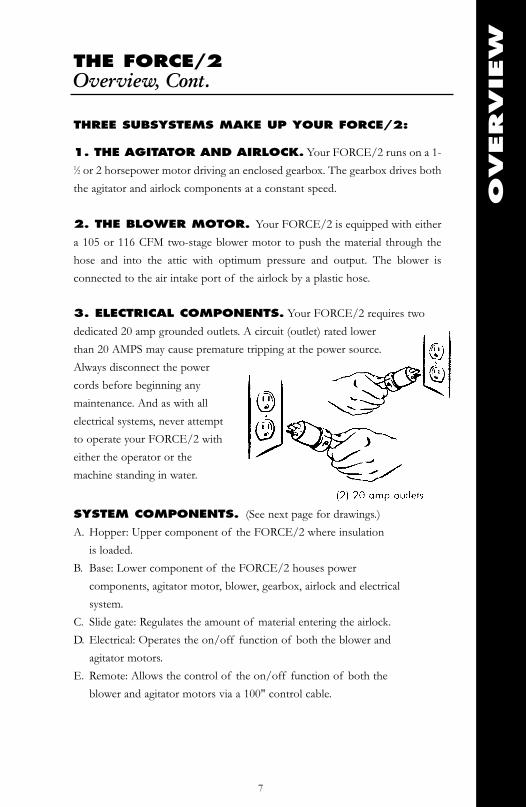
REPLACING AIRLOCK SEALS
We recommend changing the airlock seals every 300 hours, 200,000 pounds of
insulation or once a year, whichever comes first.
Unplug the FORCE/2 from electrical power and empty all insulation material
from the hopper. Seal replacement requires a 7/16" socket and ratchet, a 6"
socket extension and a 7/16" open-end wrench. With the machine in an upright
position, locate the seven 1⁄4*20 bolts holding the seal in place. Loosen and remove
the fasteners. Remove the damaged seal from the rotor shaft. Reverse the process
to install a new seal. Be careful that the direction of the seal is correct. Seal must
be equally wrapped around both sides and seated all the way down on the rotor
shaft! Snug down the bolts. Do not overtighten. Overtightening will cause the
seal to bow out at the ends producing uneven wear and premature failure. To
replace other damaged seals, reconnect electrical power and, using the remote
switch, move the airlock seal into the position for removal. Again, disconnect
from electrical power before doing the actual repair or replacement. Note: Do
not install the seals backwards. See pages 32 and 33 for additional
illustrations.
MAIN
TEN
AN
CE
20
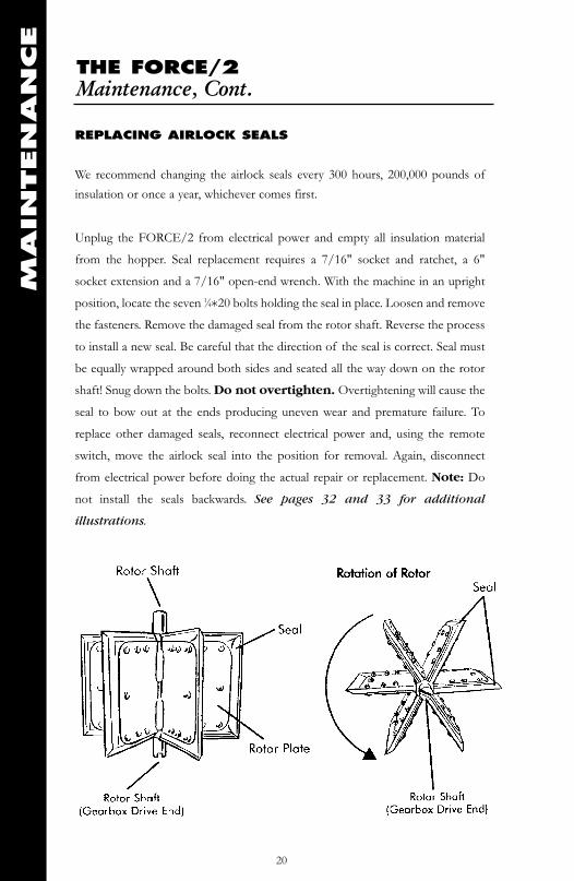
GEARBOXThe oil in the gearbox of your FORCE/2 should be changed every year to ensureproper lubrication of the gears and seals.
Changing oil in all direct drive models:
Model 22015 Place the machine on its side with clear access to the twodrain/fill plugs on the gearbox. Place a drain pan under eachplug to catch the used oil. Remove the drain plug from eachof the two gearbox chambers with a 90º 3/8 inch hexwrench. Drain the oil into the pans. To refill, pour fourounces of oil into a six ounce disposable paper cup. Bendcup lip to form a pouring spout. Pour a total of 20 ouncesinto worm gear case and 16 ounces into bevel gear case, and reinstall plugs using thehex wrench. Note: At cold temperatures, oil thickens, slowing the draining process.Leave your machine in a warm area overnight (eight hours) to make oil changingeasier. See illustration for the location of the drain/fill plugs.
Recommended gearbox oil: Model 22015 (Mfg. from 7/89 - 11/02)Temperature 40˚ - 100˚ F Mobil SHC 634 gear lubeTemperatures -20˚ - +40˚ F Mobil 1 synthetic 5W-30Worm gear case capacity 20 oz.Bevel gear case capacity 16 oz.
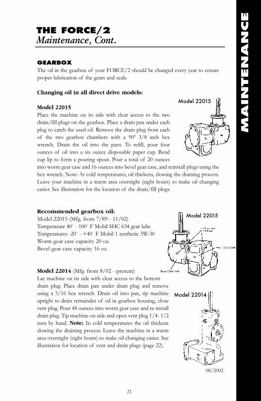
Model 22014 (Mfg. from 8/02 - present)Lay machine on its side with clear access to the bottomdrain plug. Place drain pan under drain plug and removeusing a 5/16 hex wrench. Drain oil into pan, tip machineupright to drain remainder of oil in gearbox housing, closevent plug. Pour 48 ounces into worm gear case and re-installdrain plug. Tip machine on side and open vent plug 1/4- 1/2turn by hand. Note: In cold temperatures the oil thickensslowing the draining process. Leave the machine in a warmarea overnight (eight hours) to make oil changing easier. Seeillustration for location of vent and drain plugs (page 22).
THE FORCE/2Maintenance, Cont.
MAIN
TEN
AN
CE
Model 22015
Model 22014
21
Model 22015
08/2002

THE FORCE/2Maintenance, Cont.
MAIN
TEN
AN
CE
Recommended gearbox oil: Model 22014Capacity: 48 oz.Temperature 40˚ - 100˚ F Mobil SHC 634 gear lubeTemperatures -20˚ - +40˚ F Mobil 1 synthetic 5W-30
Gearbox/Agitator/Airlock Unjamming procedure: Empty hoper,disconnect all electrical cords to machine. Tip machine upside down onto hopper.Remove agitator motor cover on outside of machine (black plastic). Locate andremove fan cover on agitator motor. Note: Depending upon the motor used it willbe necessary to remove the screws holding the fan cover on before removal,otherwise all other covers may be pried off using screwdriver. By hand, carefully turnfan blade counter-clockwise until jam is cleared. Note: It will take approximately 15turns of the fan blade before you start to reverse the entire airlock system. Caution!Fan blade may break if excessive force is used.
Note: The gearbox and the airlock must be perpendicular to each other. Properalignment prevents premature wear on the gearbox and airlock shaft connection.
Drain & Fill plug
Model 22014
Vent Plug1⁄4 - 1⁄2 Turn to Vent
22
Removing Cover Rotation Label Turn by hand Using Screw Driver
THE FORCE/2Maintenance, Cont.
BLOWER MAINTENANCE
Keeping the blower as clean as possible will avoid system overheating.
Overheating will cause lowered production, possible system failure and shorten
the expected life of your FORCE/2. Inspect blower brushes every three
months or 100 hours of use. Replace brushes when they reach 1⁄4 inch or less in
length. Change the brushes before the brush stunt touches the commutator.
When reassembling, the lead wires must be isolated from the motor frame and
any rotating parts. For optimum performance, new brushes must be properly
seated against the commutator before operating your FORCE/2 at full power.
NOTE: BRUSH INSTALLATION
After installation of new brushes, plug in machine as normal and set blower
speed control (variable speed) at 30% of full power, run for 1⁄2 hour. Set blower
speed control at 70% of full power, run for 1⁄2 hour.
CLEANING
Use compressed air to blow out motor and intake of blower every 20-30
hours of use to maximize blower impeller and motor life.
Blower Warranty Considerations. The following
blower abuse is not covered by warranty:
Damage in shipment
Visible moisture damage such as rust
Rust or other corrosion on motor exterior
Dirty motor or insulation buildup in impeller
Broken components, i.e. brushes, brush holder, etc.
User modification of blower, holes, etc.
User rewound armatures or fields
Evidence of user disassembly
Evidence of foreign object in fan end of motor
MAIN
TEN
AN
CE
23

REPLACING BLOWER BRUSHES
Model 21025 (105 CFM) brush replacement not recommended
Model 21024 (116 CFM) shown
Removing old brushes: Disconnect all
electrical cords to machine. Tip machine
upside down onto hopper. To facilitate
replacement of the blower brushes
remove blower from machine. Locate
brush clips (fig 1), using flat
screwdriver place screwdriver under brush clip as shown (fig 2), pry in an upward
motion until loose. Remove brush clip and brush assembly from motor housing
(fig 3). Remove wire connector from tab on brush assembly (fig 4).
Installing new brushes: Push wire connector onto brush tab and ensure
connection is secure. Insert brush into housing with the tab and wire in the down
position. Slide brush assembly all the way into motor housing until it stops. Push
down and inward on brush assembly, slide brush clip into top of motor housing to
secure brush assembly (fig 5). When finished make sure the brush clip is flush or
below motor housing (fig 6).
Note: Brush clip can only be installed one way. Do not forcebrush clip into motor housing or damage may occur!
THE FORCE/2Maintenance, Cont.
MAIN
TEN
AN
CE
24
blower clip
fig 5 fig 6
fig 3
fig 4
fig 2fig 1
THE FORCE/2Troubleshooting
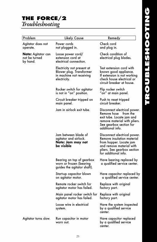
Agitator does not Power cords Check cordoperate. not plugged in. and plug in.
Note: Agitator can Loose power cord/ Check condition ofnot be turned extension cord at electrical plug blades.by hand. electrical connection.
Electricity not present at Test extension cord withBlower plug. Transformer known good appliance.in machine not receiving If extension is not workingelectricity. check house electrical or
circuit breaker at house.
Rocker switch for agitator Flip rocker switchis not in “on” position. “on” at main panel.
Circuit breaker tripped on Push to reset trippedmain panel. circuit breaker.
Jam in airlock exit tube. Disconnect electrical power. Remove hose from the exit tube. Locate jam and remove material with pliers.See gearbox section foradditional info.
Jam between blade of Disconnect electrical power.agitator and airlock. Remove insulation materialNote: Jam may not from hopper. Locate jambe visible and remove material with
pliers. See gearbox sectionfor additional info.
Bearing on top of gearbox Have bearing replaced byworn or frozen (bearing a qualified service center.guides the agitator shaft).
Start-up capacitor blown Have capacitor replaced byon agitator motor. a qualified service center.
Remote rocker switch for Replace with originalagitator motor has failed. factory part.
Main panel rocker switch for Replace with originalagitator motor has failed. factory part.
Loose wire in electrical Have the system inspected system. by a qualified service
center.
Agitator turns slow. Run capacitor in motor Have capacitor replacedworn out. by a qualified service
center.
TRO
UBLESHO
OTIN
G
Problem Likely Cause Remedy
25

THE FORCE/2Troubleshooting, Cont.
TRO
UBLESHO
OTIN
G
Machine makes a Gearbox drive not Loosen gearbox and grinding noise when engaged with airlock gearbox stabilizers. Alignrunning. rotor connection out gearbox and airlock shaft
of alignment. perpendicular to each other.Resecure bolts. Replacegearbox stabilizers if bent.
Low oil level in gearbox. Have the gearboxinspected and repaired by aqualified service center. See gearbox section for oil capacity.
Agitator fan cover rubbing Remove black plastic coveragainst rotating fan blade. on outside of machine.
Remove agitator motor fancover and inspect fan bladeand bend cover back to normal condition.
Decreased material Worn airlock seals. Inspect seals for tears or throw. cuts. See maintenance
section to replace or adjustas necessary.
Kink in hose. Run hose as straight as possible to help maintain production.
Excess air leaking into Inspect seals for tears or hopper. cuts. See maintenance
section to replace or adjustas necessary.
Material buildup in Turn machine upside downblower housing. and use compressed air to
blow out air intake. Seediagram.
Machine does not run Remote cord not plugged Plug in remote cord into into electrical panel electrical panel and position
the agitator and blower switchto the on position.
Blower power cord is not Check connection on powerplugged in at main panel cord at main panel oror power cord does not make sure electricity ishave electrical power at present at power source.source.
No power. Check source of electricalpower. Possible trippedcircuit breaker.
Problem Likely Cause Remedy
26
THE FORCE/2Troubleshooting Cont.
TRO
UBLESHO
OTIN
G
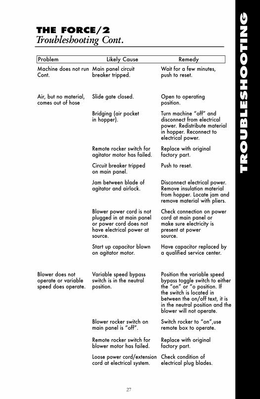
Problem Likely Cause Remedy
27
Machine does not run Main panel circuit Wait for a few minutes,Cont. breaker tripped. push to reset.
Air, but no material, Slide gate closed. Open to operatingcomes out of hose position.
Bridging (air pocket Turn machine “off” and in hopper). disconnect from electrical
power. Redistribute materialin hopper. Reconnect to electrical power.
Remote rocker switch for Replace with originalagitator motor has failed. factory part.
Circuit breaker tripped Push to reset.on main panel.
Jam between blade of Disconnect electrical power. agitator and airlock. Remove insulation material
from hopper. Locate jam and remove material with pliers.
Blower power cord is not Check connection on power plugged in at main panel cord at main panel or or power cord does not make sure electricity is have electrical power at present at power source. source.
Start up capacitor blown Have capacitor replaced byon agitator motor. a qualified service center.
Blower does not Variable speed bypass Position the variable speed operate or variable switch is in the neutral bypass toggle switch to eitherspeed does operate. position. the “on” or “o position. If
the switch is located in between the on/off text, it is in the neutral position and theblower will not operate.
Blower rocker switch on Switch rocker to “on”,use main panel is “off”. remote box to operate.
Remote rocker switch for Replace with originalblower motor has failed. factory part.
Loose power cord/extension Check condition of cord at electrical system. electrical plug blades.

THE FORCE/2Troubleshooting Cont.
TRO
UBLESHO
OTIN
G
Blower does not Loose wire in electrical Have the system inspected operate or variable system. and repaired by a speed does operate. qualified service center.
Worn brushes in blower motor Have the brushes inspectedand replaced by a qualified service center.
Inline fuse blown. Turn machine upsidedown. Locate fuse holderon electrical box. Removeblown fuse and replacewith 15 amp AG style fuse.
Agitator trips circuit Low voltage 99-104v. FORCE/2 requires abreaker at main minimum of 20 amps panel. @ 115V. Relocate power
cord to a dedicated 20 amp circuit.
Incorrect size extension cord. For an additional 50' run, use 10/3 cord. For a 100' run use 8/3 cord.
Pushing down on material Do not push down on in hopper. insulation while filling hopper.
Wet insulation material in Do not use wethopper. material. Disconnect
electrical power andremove wet material.
Worn or frozen airlock Have bearing checked and bearing. replaced by a qualified
technician.
Blower trips circuit Low voltage. Blower requires a minimum breaker at power of 20 amps @ 115V. Use a source. dedicated refrigerator outlet
or equivalent.
Incorrect extension cord. For an additional 50' run, use 10/3 cord. For a 100' run use 8/3 cord.
Operator in attic Static electricity from Mix half-and-half solution keeps getting insulation. of water and fabric softener.shocked. Mist into insulation while
loading hopper. Note:Excess moisture will cause jamming.
Problem Likely Cause Remedy
28
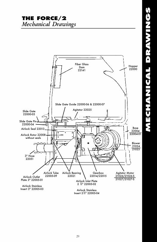
Fiber GlassDam
22141Hopper22000
Slide Gate Guide 22000-06 & 22000-07
Agitator 22025Slide Gate22000-03
Airlock Seal 22013
Airlock Rotor 22008without seals
3" Hose22051
Airlock Bearing22021
Gearbox22014/22015
Agitator Motor21026/21026-S21027/21027-S
Blower2102421025
Base22004
22004-01
Slide Gate Pin 22000-04
THE FORCE/2Mechanical Drawings
MECHAN
ICAL
DRAW
IN
GS
29
Airlock Outlet Plate 3" 22005-01
Airlock StainlessInsert 3" 22005-03
Airlock Tube22005-09
Airlock Inlet Plate 2 1⁄2" 22005-02
Airlock Stainless Insert 21⁄2" 22005-04
MECHAN
ICAL
DRAW
IN
GS
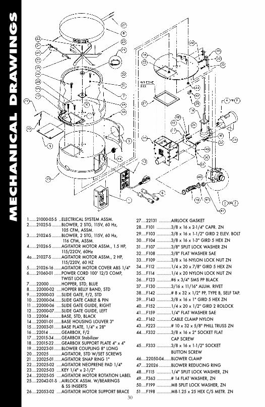
1......21000-05-S ..ELECTRICAL SYSTEM ASSM.2......21025-S ........BLOWER, 2 STG, 115V, 60 Hz,
105 CFM, ASSM.3......21024-S ........BLOWER, 2 STG, 115V, 60 Hz,
116 CFM, ASSM.4......21026-S ........AGITATOR MOTOR ASSM., 1.5 HP,
115/22OV, 60Hz4a....21027-S ........AGITATOR MOTOR ASSM., 2 HP,
115/220V, 60 HZ5......21026-16 ......AGITATOR MOTOR COVER ABS 1/4"6......21060-01 ......POWER CORD 100' 12/3 COMP,
TWIST LOCK7......22000 ..........HOPPER, STD, BLUE8......22000-02 ....HOPPER BELLY BAND, STD9......22000-03 ....SLIDE GATE, F/2, STD10....22000-04......SLIDE GATE CABLE & PIN11 ....22000-06 ....SLIDE GATE GUIDE, RIGHT12....22000-07......SLIDE GATE GUIDE, LEFT13....22004 ..........BASE, STD, BLACK14....22001-01 ......BASE HOUSING LOUVER 3"15....22003-01......BASE PLATE, 1/4" x 28"16....22014 ..........GEARBOX, F/217....22015-34 ......GEARBOX Stabilizer18....22015-22 ......GEARBOX SUPPORT PLATE 4" x 4"19....22023-01......BLOWER COUPLING 8" LONG20....22025 ..........AGITATOR, STD W/SET SCREWS21....22025-01......AGITATOR SNAP RING 1"22....22025-02 ....AGITATOR NEOPRENE PAD 1/4"23....22025-03 ....KEY 1/4" x 2-1/2"24....22025-05 ....AGITATOR MOTOR ROTATION LABEL25....22042-01-S ..AIRLOCK ASSM. W/BEARINGS
& SS INSERTS26....22053-02 ....AGITATOR MOTOR SUPPORT BRACE
27....22131 ..........AIRLOCK GASKET28....F101 ............3/8 x 16 x 2-1/4" CAPR. ZN29....F103 ............3/8 x 16 x 1-1/2" GIRD 2 ELEV. BOLT30....F104 ............3/8 x 16 x 1-3" GIRD 5 HEX ZN31....F107 ............3/8" SPLIT LOCK WASHER ZN32....F108 ............3/8" FLAT WASHER SAE33....F109 ............3/8 x 16 NYLON LOCK NUT ZN34....F112 ............1/4 x 20 x 7/8" GIRD 5 HEX ZN35....F114 ............1/4 x 20 NYLON LOCK NUT ZN36....F123 ............#6 x 3/4" SMS PP BLACK37....F130 ............3/16 x 11/16" ALUM. RIVET38....F142 ............# 8 x 32 x 1/2" PP, TYPE B, SELF TAP.39....F143 ............3/8 x 16 x 1" GIRD 5 HEX ZN40....F152 ............1/4 x 20 x 1/2" GIRD 2 ROLOCK41....F159 ............1/4" FLAT WASHER SAE42....F162 ............CABLE CLAMP NYLON43....F223 ............# 10 x 32 x 5/8" PHILL TRUSS ZN44....F332 ............3/8 x 16 x 2" SOCKET FLAT
CAP SCREW45....F333 ............3/8 x 16 x 1-1/2" SOCKET
BUTTON SCREW46....22050-04......BLOWER CLAMP47....22026 ..........BLOWER REDUCING RING48....F115 ............1/4" SPLIT LOCK WASHER, ZN49....F363 ............# 14 FLAT WASHER, ZN50....F199 ............M8 SPLIT LOCK WASHER, ZN51....F198 ............M8-1.25 x 25 HEX C/S METR. ZN
30
MECHAN
ICAL
DRAW
IN
GS
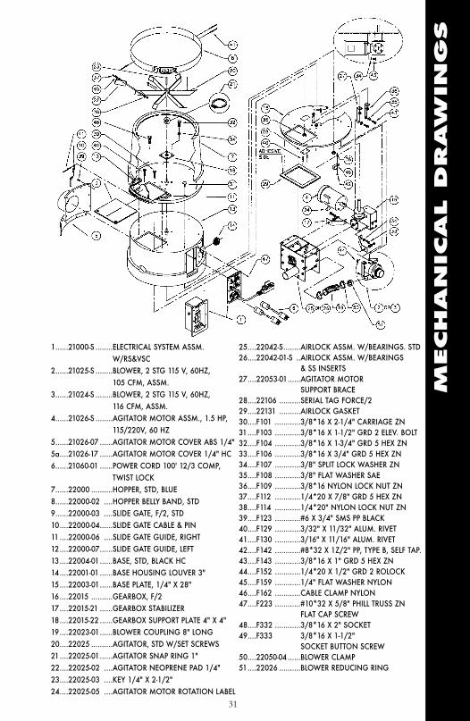
25....22042-S........AIRLOCK ASSM. W/BEARINGS. STD26....22042-01-S ..AIRLOCK ASSM. W/BEARINGS
& SS INSERTS27....22053-01......AGITATOR MOTOR
SUPPORT BRACE28....22106 ..........SERIAL TAG FORCE/229....22131 ..........AIRLOCK GASKET30....F101 ............3/8*16 X 2-1/4" CARRIAGE ZN31....F103 ............3/8*16 X 1-1/2" GRD 2 ELEV. BOLT32....F104 ............3/8*16 X 1-3/4" GRD 5 HEX ZN33....F106 ............3/8*16 X 3/4" GRD 5 HEX ZN34....F107 ............3/8" SPLIT LOCK WASHER ZN35....F108 ............3/8" FLAT WASHER SAE36....F109 ............3/8*16 NYLON LOCK NUT ZN37....F112 ............1/4*20 X 7/8" GRD 5 HEX ZN38....F114 ............1/4*20" NYLON LOCK NUT ZN39....F123 ............#6 X 3/4" SMS PP BLACK40....F129 ............3/32" X 11/32" ALUM. RIVET41....F130 ............3/16" X 11/16" ALUM. RIVET42....F142 ............#8*32 X 1Z/2" PP, TYPE B, SELF TAP.43....F143 ............3/8*16 X 1" GRD 5 HEX ZN44....F152 ............1/4*20 X 1/2" GRD 2 ROLOCK45....F159 ............1/4" FLAT WASHER NYLON46....F162 ............CABLE CLAMP NYLON47....F223 ............#10*32 X 5/8" PHILL TRUSS ZN
FLAT CAP SCREW48....F332 ............3/8*16 X 2" SOCKET 49....F333 3/8*16 X 1-1/2"
SOCKET BUTTON SCREW50....22050-04 ......BLOWER CLAMP51....22026 ..........BLOWER REDUCING RING
1......21000-S ........ELECTRICAL SYSTEM ASSM. W/RS&VSC
2......21025-S ........BLOWER, 2 STG 115 V, 60HZ, 105 CFM, ASSM.
3......21024-S ........BLOWER, 2 STG 115 V, 60HZ, 116 CFM, ASSM.
4......21026-S ........AGITATOR MOTOR ASSM., 1.5 HP, 115/220V, 60 HZ
5......21026-07 ......AGITATOR MOTOR COVER ABS 1/4"5a....21026-17 ......AGITATOR MOTOR COVER 1/4" HC6......21060-01 ......POWER CORD 100' 12/3 COMP,
TWIST LOCK7......22000 ..........HOPPER, STD, BLUE8......22000-02 ....HOPPER BELLY BAND, STD9......22000-03 ....SLIDE GATE, F/2, STD10....22000-04......SLIDE GATE CABLE & PIN11 ....22000-06 ....SLIDE GATE GUIDE, RIGHT12....22000-07......SLIDE GATE GUIDE, LEFT13....22004-01......BASE, STD, BLACK HC14....22001-01 ......BASE HOUSING LOUVER 3"15....22003-01......BASE PLATE, 1/4" X 28"16....22015 ..........GEARBOX, F/217....22015-21 ......GEARBOX STABILIZER18....22015-22 ......GEARBOX SUPPORT PLATE 4" X 4"19....22023-01......BLOWER COUPLING 8" LONG20....22025 ..........AGITATOR, STD W/SET SCREWS21....22025-01......AGITATOR SNAP RING 1"22....22025-02 ....AGITATOR NEOPRENE PAD 1/4"23....22025-03 ....KEY 1/4" X 2-1/2"24....22025-05 ....AGITATOR MOTOR ROTATION LABEL
31

MECHAN
ICAL
DRAW
IN
GS
32
Item # PART NUMBER DESCRIPTION1 ..............22005-02 ..................AIRLOCK INLET PLATE ASSM. 2 1/2"2 ..............22005-09 ..................AIRLOCK TUBE 12" (CRS)3 ..............22005-01 ..................AIRLOCK OUTLET PLATE ASSM. 3"4 ............22021........................AIRLOCK BEARING FLANGE 4 HOLE5 ..............22008 ......................AIRLOCK ROTOR ASSEMBLY W/O SEAL6 ..............22013........................AIRLOCK SEAL 7 ..............22116 ........................AIRLOCK WEAR WASHER8 ..............F221..........................CAGE NUT ZN9 ..............F353..........................3/8" INTERNAL LOCK WASHER ZN10 ............F108..........................3/8" FLAT WASHER SAE11 ............F159..........................1/4" SAE FLAT WASHER12 ............F114 ..........................1/4*20 NYLON LOCKNUT ZN13 ............F112 ..........................1/4*20 x 7/8" GRADE 5 HEX HEAD ZN14 ............F110 ..........................1/4*20 x 1 #9 HEX YELL. ZN15 ............F105..........................3/8–24 x 7/8" GRADE 5 HEX HEAD ZN16 ............F115 ..........................1/4" SPLIT LOCK WASHER ZN17 ............22005-03 ..................OUTLET SS INSERT 3"18 ............22005-04 ..................INLET SS INSERT 2-1/2"
Airlock Assembly

MECHAN
ICAL
DRAW
IN
GS
33
Item # PART NUMBER DESCRIPTION1 ............22008 ................AIRLOCK ROTOR ASSM. W/O SEALS2 ............22013 ................AIRLOCK SEAL3 ............22116 ................WEAR WASHER NYLON 5/8"4 ............F112 ..................1/4*20x7/8 GRADE 5 HEX HEAD ZN5 ............F114 ..................1/4*20 NYLON LOCKNUT ZN
Airlock Rotor

MECHAN
ICAL
DRAW
IN
GS
34
Item # PART NUMBER DESCRIPTION1 ............21025 ................BLOWER 2 STG., 115V, 60 Hz, 105 CFM1 ............21024 ................BLOWER 2 STG., 115V, 60 Hz, 116 CFMn/a ........21025-05............Blower Brush (set of two)2 ............22022-- ..............BLOWER MOUNTING BRACKET3 ............22022-01............BLOWER MOUNTING BRACKET 6-3/4"4 ............F112 ..................1/4*20 X 7/8" GRADE 5 HEX, ZN5 ............F114 ..................1/4" NYLON INSERT LOCKNUT, ZN6 ............F146 ..................ELECTRICAL BOX FEMALE CONTACT7 ............F159 ..................1/4" SAE FLAT WASHER
Model 21025 105 CFM Blower
Model 21024116 CFM Blower

ELECTRICAL
DRAW
IN
GS
35
Item # PART NUMBER DESCRIPTION1 ............R22001-02..........ELECTRICAL BOX W/HOLES2 ............21012-00-S..........REMOTE CORD 18/7 x 100' COMP. W/RS & VSC3 ............21016-S ..............ELECTRICAL PANEL ASSM. 4 ............21002 ................TRANSFORMER 110 VOLT5 ............21003-02............ELECTRICAL CONTACTOR (2 HP)6 ............21003-03............ELECTRICAL CONTACTOR MOUNT RAIL7 ............21017-02 ............FUSE HOLDER, BLOWER8 ............21019 ................ELECTRICAL BOX FLANGE CONNECTOR9 ............21020 ................ELECTRICAL BOX MOUNTING PLATE10 ..........21025-07 ............FUSE, 15 AMPS11 ..........21143-06 ............VARIABLE SPEED CONTROL12 ..........F120 ..................8*32 NYLON INSERT LOCK NUT13 ..........F126 ..................8*32 X 1 4 PP ZN14 ..........F158 ..................#6 X 1/2" SMS PP ZN15 ..........F223 ..................10*32 X 5/8" PT ZN16 ..........F141 ..................8*32 X 1/2" PP ZN
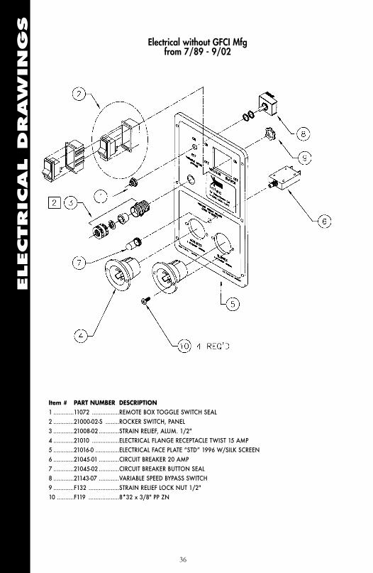
Electrical without GFCI Mfgfrom 7/89 - 9/02
ELECTRICAL
DRAW
IN
GS
Item # PART NUMBER DESCRIPTION1 ............11072 ................REMOTE BOX TOGGLE SWITCH SEAL2 ............21000-02-S ........ROCKER SWITCH, PANEL3 ............21008-02............STRAIN RELIEF, ALUM. 1/2"4 ............21010 ................ELECTRICAL FLANGE RECEPTACLE TWIST 15 AMP5 ............21016-0 ..............ELECTRICAL FACE PLATE “STD” 1996 W/SILK SCREEN6 ............21045-01 ............CIRCUIT BREAKER 20 AMP7 ............21045-02 ............CIRCUIT BREAKER BUTTON SEAL8 ............21143-07 ............VARIABLE SPEED BYPASS SWITCH9 ............F132 ..................STRAIN RELIEF LOCK NUT 1/2"10 ..........F119 ..................8*32 x 3/8" PP ZN
36
Electrical without GFCI Mfgfrom 7/89 - 9/02

ELECTRICAL
DRAW
IN
GS
37
Item # PART NUMBER DESCRIPTION1 ............21008-0 ..............REMOTE BOX 3/4 W/HOLE2 ............21008-09............STRAIN RELIEF, ALUMINUM, 3/4"3 ............21008-10 ............REMOTE CORD 18/7 X 100' (ONLY)4 ............21008-12 ............REMOTE BOX CONNECTOR SOCKET MALE5 ............21008-13 ............REMOTE BOX CONNECTOR SOCKET FEMALE6 ............21008-14 ............REMOTE BOX CONTACT PIN MALE7 ............21008-15 ............REMOTE BOX CONTACT PIN FEMALE8 ............21008-17 ............REMOTE BOX 3/4" SHIELD STICKER9 ............21143-01 ............VARIABLE SPEED KNOB10 ..........21021-S ..............REMOTE BOX ROCKER SWITCH ASSM.11 ..........21143-03-S..........VSC POT. ASSM.12 ..........RR21008-08 ........REMOTE BOX 3/4" SHIELD W/O STICKER13 ..........F119 ..................8*32 X 3/8 PP ZN14 ..........F122 ..................6*32 X 3/8 PP BLACK15 ..........F124 ..................6*32 NYLON INSERT LOCK NUT16 ..........F153 ..................#6 RING TERMINAL BLUE
Electrical without GFCI Mfgfrom 7/89 - 9/02

ELECTRICAL
DRAW
IN
GS
38
Wiring DiagramMfg from 7/89 - 9/02
Electrical with Variable SpeedControl in Remote Cord
ELECTRICAL
DRAW
IN
GS
39
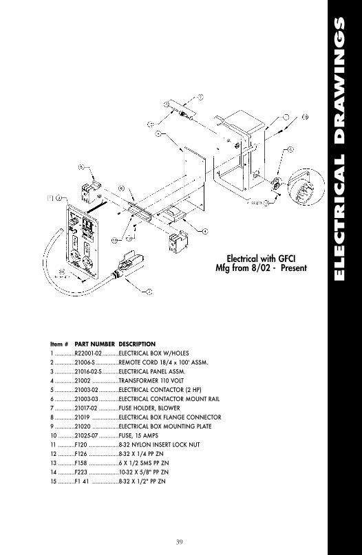
Item # PART NUMBER DESCRIPTION1 ............R22001-02..........ELECTRICAL BOX W/HOLES2 ............21006-S ..............REMOTE CORD 18/4 x 100' ASSM.3 ............21016-02-S..........ELECTRICAL PANEL ASSM.4 ............21002 ................TRANSFORMER 110 VOLT5 ............21003-02............ELECTRICAL CONTACTOR (2 HP)6 ............21003-03............ELECTRICAL CONTACTOR MOUNT RAIL7 ............21017-02 ............FUSE HOLDER, BLOWER8 ............21019 ................ELECTRICAL BOX FLANGE CONNECTOR9 ............21020 ................ELECTRICAL BOX MOUNTING PLATE10 ..........21025-07 ............FUSE, 15 AMPS11 ..........F120 ..................8-32 NYLON INSERT LOCK NUT12 ..........F126 ..................8-32 X 1/4 PP ZN13 ..........F158 ..................6 X 1/2 SMS PP ZN14 ..........F223 ..................10-32 X 5/8" PP ZN15 ..........F1 41 ................8-32 X 1/2" PP ZN
Electrical with GFCI Mfg from 8/02 - Present

ELECTRICAL
DRAW
IN
GS
40
Item # PART NUMBER DESCRIPTION12 ..........F119 ..................8-32X3/8 PP ZN13 ..........F223 ..................10-32X5/8 FIL TRUSS ZN14 ..........21000-02............ROCKER SWITCH, PANEL15 ..........21008-02............STRAIN RELIEF, ALUM. 1/2"16 ..........21010 ................ELECTRICAL FLANGE RECEPTACLE, TWIST 15 AMP.3417 ..........21016-03 ............ELECTRICAL FACE PLATE "OC" W/SILK SCREEN18 ..........21045-01 ............CIRCUIT BREAKER 20 AMP.19 ..........21045-02 ............CIRCUIT BREAKER BUTTON SEAL20 ..........01002 ................GROUND FAULT CIRCUIT, 20 AMP.21 ..........F132 ..................STRAIN RELIEF LOCK NUT 1/2"30 ..........F124 ..................6-32 NYLON INSERT LOCK NUT
Electrical with GFCI Mfg from 8/02 - Present

ELECTRICAL
DRAW
IN
GS
41
Item # PART NUMBER DESCRIPTION22 ..........21008-0 ..............REMOTE BOX 3/4" W/HOLE23 ..........21008-09............STRAIN RELIEF, ALUM. 3/4"24 ..........21008-03............REMOTE CORD 18/4X100' (ONLY)25 ..........01009 ................REMOTE BOX 31" SHIELD STICKER26 ..........RR21021-01 ........REMOTE BOX ROCKER SWITCH26A........11008-06-01-S ....REMOTE BOX ROCKER SWITCH ASSM.27 ..........RR21004 ............REMOTE BOX 3/4" SHIELD W/O STICKER28 ..........F119 ..................8-32X3/8 PP ZN29 ..........F122 ..................6-32X3/8 PP ZN30 ..........F124 ..................6-32 NYLON INSERT LOCK NUT31 ..........F153 ..................#6 RING TERMINAL, BLUE32 ..........F136 ..................BUTT SPLICE, BLUE33 ..........F230 ..................SHRINK TUBE 3/16X1/4", WHITE34 ..........F231 ..................SHRINK TUBE 3/16X1/4", RED
Electrical without GFCI Mfgfrom 7/89 - Present
Electrical with GFCI Mfgfrom 8/02 - Present
Remote Box Assembly

ELECTRICAL
DRAW
IN
GS
42
Item # PART NUMBER DESCRIPTION1 ............22001-03............ELECTRICAL BOX W/CURVE, WHOLES2 ............21002 ................TRANSFORMER 110 VOLT3 ............21003-02............ELECTRICAL CONTACTOR (2 HP)4 ............21003-03............ELECTRICAL CONTACTOR MOUNT RAIL5 ............21017-02 ............FUSE HOLDER, BLOWER6 ............21019 ................ELECTRICAL BOX FLANGE CONNECTOR7 ............21020-01 ............ELECTRICAL BOX MOUNTING PLATE 1/8 X 5 X 6-3/88 ............21025-07 ............FUSE, 15 AMPS9 ............F120 ..................8-32 NYLON INSERT LOCK NUT10 ..........F126 ..................8-32 X 1/4 PP ZN11 ..........F158 ..................6 X 1/2 SMS PP ZN12 ..........F141 ..................B-32 X 1/2" PP ZN
Electrical with GFCI Mfg from 8/02 - Present
VERSION A

ELECTRICAL
DRAW
IN
GS
43
Item # PART NUMBER DESCRIPTION1 ............R22001-02..........ELECTRICAL BOX W/ HOLES2 ............21002 ................TRANSFORMER 110 VOLT3 ............21003-02............ELECTRICAL CONTACTOR (2 HP)4 ............21003-03............ELECTRICAL CONTACTOR MOUNT RAIL5 ............21017-02 ............FUSE HOLDER, BLOWER6 ............21019 ................ELECTRICAL BOX FLANGE CONNECTOR7 ............21020 ................ELECTRICAL BOX MOUNTING PLATE 8 ............21025-07 ............FUSE, 15 AMPS9 ............F120 ..................8-32 NYLON INSERT LOCK NUT10 ..........F126 ..................8-32 X 1 4 PP ZN11 ..........F158 ..................6 X 1/2 SMS PP ZN12 ..........F141 ..................B-32 X 1/2" PP ZN
Electrical with GFCI Mfg from 8/02 - Present
VERSION B

ELECTRICAL
DRAW
IN
GS
44
Wiring Diagram Manufactured from 8/02 - Present
Electrical with GFCI

ELECTRICAL
DRAW
IN
GS
45
Item # PART NUMBER DESCRIPTION1 ............21006-S ..............REMOTE CORD/BOX 18/4X100' ASSM.
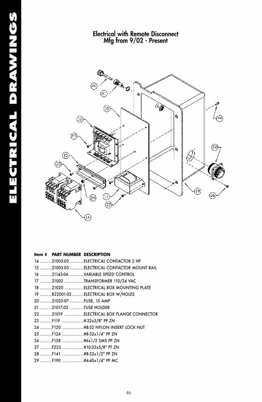
(see page 41 for more detailed remote cord drawings)2 ............11072 ................REMOTE BOX TOGGLE SWITCH SEAL 3 ............21000-03............ROCKER SWITCH, BLACK4 ............21000-04 ............ROCKER SWITCH, RED5 ............21000-02............ROCKER SWITCH PANEL6 ............21010 ................ELEC. FLANGE RECEPT. TWIST 15AMP7 ............21016-02 ............ELECTRICAL FACE PLATE 20028 ............21045-01 ............CIRCUIT BREAKER 20 AMP9 ............21045-02 ............CIRCUIT BREAKER BUTTON SEAL10 ..........21143-07 ............VARIABLE SPEED BYPASS SWITCH11 ..........21143-05-S..........VS POTENTIOMETER 1K, ASSM.12 ..........21143-01 ............VARIABLE SPEED KNOB13 ..........21021 ................REMOTE QUICK DISCONNECT FEMALE RECEPTACLE23 ..........F119 ..................#-32X3/8" PP ZN27 ..........F223 ..................#10-32X5/8" PT ZN29 ..........F190 ..................#4-40X1/4" PP ZN
Electrical with RemoteDisconnect
Mfg from 9/02 - Present
ELECTRICAL
DRAW
IN
GS
46
Item # PART NUMBER DESCRIPTION14 ..........21003-02............ELECTRICAL CONTACTOR 2 HP15 ..........21003-03............ELECTRICAL CONTACTOR MOUNT RAIL 16 ..........21143-06 ............VARIABLE SPEED CONTROL17 ..........21002 ................TRANSFORMER 110/24 VAC18 ..........21020 ................ELECTRICAL BOX MOUNTING PLATE19 ..........R22001-02..........ELECTRICAL BOX W/HOLES20 ..........21025-07 ............FUSE, 15 AMP21 ..........21017-02 ............FUSE HOLDER22 ..........21019 ................ELECTRICAL BOX FLANGE CONNECTOR23 ..........F119 ..................#-32x3/8" PP ZN24 ..........F120 ..................#8-32 NYLON INSERT LOCK NUT25 ..........F126 ..................#8-32x1/4" PP ZN26 ..........F158 ..................#6x1/2 SMS PP ZN27 ..........F223 ..................#10-32x5/8" PT ZN28 ..........F141 ..................#8-32x1/2" PP ZN29 ..........F190 ..................#4-40x1/4" PP MC
Electrical with Remote DisconnectMfg from 9/02 - Present

ELECTRICAL
DRAW
IN
GS
47
Wiring DiagramMfg from 9/02 - Present
Electrical With Remote Disconnect
CLAIM
S,
DAM
AG
EO
RLO
SS
THE FORCE/2Claims, Damage or Loss
48
These goods were carefully packed and thoroughly inspected before leaving our
factory. Responsibility for its safe delivery was assumed by the carrier upon
acceptance of the shipment. Inspect shipment carefully on the arrival for damage
to contents, shortages or equipment. In case of damage, save container and
packing material for inspection. Claims for loss or damage sustained in transit
must, therefore, be made upon the carrier, as follows:
1. CONCEALED LOSS OR DAMAGE. Concealed loss or damage
means loss or damage which does not become apparent until the merchandise has
been unpacked. The contents may be damaged in transit due to rough handling
even though the carton may not show external damage. When the damage is
discovered upon unpacking, make a written request for inspection by the carrier’s
agent within ten days of the delivery date. Then file a claim with the carrier since
such a claim is the carrier’s responsibility.
2. VISIBLE LOSS OR DAMAGE. Any external evidence of
loss or damage must be noted on the freight bill or the express receipt, and signed
by the carrier’s agent. Failure to adequately describe such external evidence of loss
or damage may result in the carrier refusing to honor a damage claim. The form
required to file such a claim will be supplied by the carrier.
3. SHORTAGE. If the number of containers in the shipment does not
correspond with the transportation bill, obtain carrier's notation of shortage and
signature on transportation bill. When the number of containers is correct, but
there is indication of pilferage, notify carrier in writing with a complete list of
missing merchandise.

THE FORCE/2Claims, Damage or Loss
CLAIM
S,
DAM
AG
EO
RLO
SS
49
Claims for loss or damage must be filed with the carrier by the consignee within
24 hours after receipt of goods. We will assist you in every possible mannerbut cannot be responsible for the collection of a claim or the cost of replacementof the damaged goods.
If you have any questions regarding the above information please feel free tocontact an INTEC representative.
RETURNSWe at INTEC sincerely hope the merchandise you have just received is in excellentcondition and satisfies your expectations. If not, please look below and follow theinstructions which apply to your particular situation.
MERCHANDISE IS DAMAGED.If the carrier is UPS:
Keep the merchandise in the original packing materials and carton.
Call UPS at (800) 742-5877 or contact them using their web address:www.ups.com/using/custserv/ to notify them of the damaged package.
Fill out the information sheet on the following page and mail or fax it to theattention of the Shipping Department.
Upon return of this form and/or the damaged merchandise, we will send areplacement or credit your account.
Other than UPS:
Keep the merchandise in the original packing materials and carton.
Call the Shipping Department at the number on the following page for furtherinstructions.
Upon return of this form and/or the damaged merchandise by the carrier, we willsend you a replacement or credit your account. Do not return any merchandisethrough the U.S. Post Office.
MERCHANDISE IS PERSONALLYUNSATISFACTORY TO YOU.
You may return the merchandise, along with a RMA number on outside of cartonand a copy of your invoice to the Shipping Department at the address providedon the next page. Upon its return intact, we will send a refund or credit youraccount. A restocking fee may be charged.

THE FORCE/2Returns
SHIPMENTS TO FACTORY
All shipments to the factory must have a RMA number on the outside of the carton. You
will be given a RMA number when you contact the Sales Department. The RMA is the
only way to track and assure that your request is handled properly. If you received an
invoice with your merchandise, please include a copy of the invoice with all returned
materials.
Company Name________________________________________
Contact Name ________________________________________
Phone________________________ Fax ____________________
Address ______________________________________________
City_____________________ State____ Zip ____________________
Comments ____________________________________________
________________________________________________________________________________________________________________________________________________________________________________________________________________________
________________________________________________________________________________________________________________________________________________________________________________________________________________________
Invoice Number________________ RMA Number ____________
Shipping Department Ph: 1-303-833-6644INTEC 1-800-666-16113771 Monarch Street Fax: 1-303-833-6650Frederick, CO 80530 E-mail: [email protected]
RETURN
S
50
THE FORCE/2Receiving Replacement Parts
51
RECEIVIN
GREPLACEM
EN
TPARTS
When you call INTEC, please have available the model number and serialnumber of your machine, as well as description of the defective part or anexplanation of the defect.
We will issue a Return Merchandise Authorization (RMA) number andinstructions to return the defective part. All shipments to INTEC must be sentvia UPS, except in the case of complete machines, when a common carriershould be used. The warranty on your machine does not cover freight or laborcharges. All shipments to the factory or service center must be freight prepaid.No freight collect shipments will be accepted without prior approval.
Your RMA number must appear on the outside of any returnedcartons. We assume no responsibility for incoming lost oruntraceable shipments. RMA numbers expire 30 days after issuedate. Shipments beyond the 30-day expiration may not becredited.
We will repair or replace, at our option, any returned part found to be defectivein materials or workmanship under the terms of our limited warranty. Repairedor replaced parts will be returned to you freight collect.
If we determine the part failure was due to misuse, alteration, negligence,accident or operating beyond rated capacity, we will contact you. At your option,we will send you a new part at the prevailing price or return the failed part to you.All shipments from the factory are sent freight collect.
If you require a replacement part prior to a warranty decision, we will send thepart to you at the prevailing price, under your current terms. When we receivethe defective part and a warranty decision has been made, INTEC will eitherissue a credit to your account or return the failed part to you.
Shipping Department Ph: 1-303-833-6644INTEC 1-800-666-16113771 Monarch Street Fax: 1-303-833-6650Frederick, CO 80530 E-mail: [email protected]

THE FORCE/2Warranty
WARRAN
TY
It is expressly understood and agreed that no officer, agent, salesman or employee
of the Manufacturer INTEC has the authority to obligate the Manufacturer by any terms, stipula-
tions, or conditions not herein expressed; that all previous representations and agreements, either
verbal or written, referring to the machinery and equipment, which is the subject of this Warranty,
are hereby superseded and canceled, and that there are no promises or agreements outside of this
Warranty agreement. Furthermore, the manufacturer hereby disclaims any implied warranties of
merchantability, or implied warranties of fitness for a particular purpose.
With the above understanding, the Manufacturer's FORCE/2 insulation blowing machine is sold
with the following one (1) year Limited Warranty, and no other:
a) Manufacturer warrants to the original purchaser that the machine is well made, of good material
and durable; but only if the machine is operated and maintained in accordance with this Operator's
Manual and the Maintenance Manual. This Warranty is void if the machine is not so operated and
maintained, or if the machine is used for blowing materials other than those which are intended to
be used with the machine.
b) Manufacturer guarantees the machine to be free from manufacturing defects at the time of
shipment, and to remain free from defects when operated under normal use, for a period of one
(1) year from the date of factory shipment, with the exception of the blower, electrical and airlock
components, which are guaranteed for a period of ninety (90) days from date of factory shipment.
c) This Warranty shall not apply to any machine or component part which, in the opinion of the
Manufacturer, has been altered, subject to misuse, negligence, accident or operated beyond factory
rated capacity. All requested Warranty work shall be performed at Manufacturer's factory or by an
Authorized Factory Service Facility. Failure to have the Warranty work done at Manufacturer’s
factory or by an Authorized Factory Service Facility will void this Warranty. Manufacturer will bear
full responsibility to repair or replace, at its option, without charge to the original purchaser, any
part which, in the Manufacturer's opinion, is found to be defective.
d) All parts claimed defective by original purchaser shall be returned, properly
identified, to Manufacturer's factory or Authorized Factory Service facility, freight prepaid. All
replacement, repaired or non-defective parts will be returned to purchaser, freight collect.
Manufacturer will supply replacement parts prior to receipt of any parts claimed defective, only
with the understanding that such replacement parts will be shipped to purchaser at the then
prevailing price of said part, C.O.D., freight collect. Manufacturer will reimburse cost of any such
part only after receipt and inspection, and finding said part defective.
e) Manufacturer's liability is expressly limited to the repair or replacement of defective parts set
forth in this Warranty. All other damages and warranties, statutory or otherwise, being waived by
original purchaser as a condition of sale and purchase of said machines. Furthermore, the
Manufacturer shall not be liable for damages or delays caused by defective material or
workmanship.
This Warranty applies only to the original purchaser and is not transferable.
52

THE FORCE/2Insulation Terms and Values
R-VALUE: The resistance (R) to heat or cold. The higher the R Value, the
greater the resistance and the better the insulation factor.
SETTLEMENT: All blown insulation will settle after installation. Your
FORCE/2 installs near settled density. Consult the chart on the material bag
for coverage and install accordingly.
COVERAGE: Every bag of material comes with a coverage chart
detailing R-Value ratings. Average ratings for various materials are:
Cellulose: R = 3.7 per inch
Rockwool: R = 2.6 per inch
Fiberglass: R = 2.2 per inch
CFM: Blowers are measured by Cubic Feet per Minute. A low CFM blower
reduces “dust” when blowing insulation into an attic. The FORCE/2 features
the lowest CFM of all insulation blowing machines, minimizing the “dust”
problem. You’ll be able to see what you are doing.
PSI: Blowers are also rated by Pounds of pressure per Square Inch. A high
PSI does a better job of blowing insulation. Your FORCE/2 produces 3.2-4.0
PSI which is the best for blowing insulation.
BRIDGING: A pocket of air, or void, created by improper agitation in the
hopper. A “bridge” can stop production until cleared. Your FORCE/2 is
designed with a non-bridging hopper. However, you may experience a
temporary bridge while using your machine. Waiting a few seconds will most
likely clear a temporary bridge. If not, unplug your machine and redistribute
the material in the hopper.
VENTILATION: Proper air flow requires one square foot of air
movement for every 150 square feet of attic area.
AIRLOCK SEAL: Also known as flapper, rubbers, paddles.
IN
SULATIO
NTERM
SAN
DVALUES
53

THE FORCE/2Insulation Terms and Values, Cont.
COMMON INSULATION VALUES
Material Thickness R-Value
Air Space 1" 1.01
Cellulose loose fill 1" 3.70
Celotex 1" 3.03
Concrete block 8", hollow 1.11
Fiberglass batt 31⁄2" 11.0
Fiberglass batt 8" 19.0
Fiberglass loose fill 1" 2.2
Rockwool batt 3⁄4" 11.0
Rockwool batt 6 - 71⁄2" 22.0
Rockwool loose fill 1" 2.60
Plywood 1⁄2" .62
Polyurethane board 1" 6.25
Vermiculite 1" 2.13
IN
SULATIO
NTERM
SAN
DVALUES
54