Embed Size (px)
Citation preview
II
NASA TECHNICAL
MEMORANDUM
NASA TMX-64755
RevisionA(NASA-TM-X-64755-Rev-?,) GUIDELINES FOR THE _78-I_311
SELECTION AdD APPLICATIO'J OF TANTALbM
ELECTROLYTIC CAPACITORS IN HIGHLY RELIABLE
EQUIPMENT (NASA) 68 p HC A0_/MF A01 gnclas
CSCi 09A G]/33 05713
GUIDELINESFORTHESELECTIONANDAPPLICATION,OFTANTALUMELECTROLYTICCAPACITORSIN "
HIGHLYRELIABLEEQUIPMENT
By Dr. A. M. Holladay
Electronics and Control Laboratory 1
January 3i, 1978
NASA
GeorgeC. k4arsha/! Space Flight Ce,_ter
Marshall S?aceFlight Center,Alabama
MSFC - Form 3190 (Rev June 1971)
1978010368
https://ntrs.nasa.gov/search.jsp?R=19780010368 2018-07-11T09:43:35+00:00Z
TECHNICAL REPORT STANDARD TITLE PAGF
1. RE,"OR'T NO. 12. GOVERNMENT ACCESSION NO. 3. RECIPIENT'S CATALOG NO.
NASA TM X-64755, Revision A I4 TITLE AND SUBTITLE 5. REPORT DATE
Guidelines for the Selection and Application of Tantalum January 31, 19786. PERFORMIhG ORGANIZATION CODE
Electrolytic Capacitors in Highly Reliable Equipment
7. AUTHOR(S) B. PERFORMING ORGANIZATION REPORt" ._
Dr. A. M. Holladay
9. PERFORMING ORGANIZATION NAME AND ADDRESS 10. WORK UNIT NO.
George C. Marshall Space Flight Center 11. CONTRACTORGRANTNO,' Marshall Space Flight Center, Alabama 35812
3. TYPE OF REPOR'," & PERIOD ("OVERED
12. SPONSORIN_ AGENCY NAME AND ADDRESS
National Aeronautics and Space Administration Technical Memorandum
Washington, D.C. 20546 I4. SPONSORINGAGENCYCODE
:S. SUPPLEMENTARY NOTES
Prepared by Electronics and Control Laboratory, Science and Engineering
1_. ABSTRACT
This document supersedes NASA TM X-64755, Jated February 1, 1973. It presents
guidelines for the selection and application of three types of tantalum electrolytic capacitors
in current use at MSFC in the design of electrical and electronic circuits for space flight
missions. In addition, the guidelines supplement requirements of existing Military Specifica-
tions used in the procurement of capacitors. A need exists for the_e guidelines to assist
designers in preventing some of the recurring, serious problem_ ,_"perienced with tantalum
electrolytic capacitors in the recent past. The three types of capacitors covered by theseguidelines are: solid (CSB09 and 13), wet foil (CLR25, 27, 35, and 37), and tantalum
cased wet slug (CLR79).
_, Iv, KEY WORDS 18. DISTRIBUTION STATEMENT
Unclassified --Unlimited
_cuR'_LA_I_(°f_h_p_]2_sE_uRITYcLAs_'r_t'h_'`_)F_.N_PA_E_2_P_EUnclassifiedUnclassifi:_.d (;8 NTISM.%I,'C • Form 329_ (Rev December 1972) I,'or sale hv Nallon:ll I'e.,'hlti¢_l hH',_rm,l(inll ,(;;,':vice, _l'_rltlgfit"l.,I, Virghli;_ 221._1
1978010368-002

TABLEOFCONTENTS
Page
I. GENERAL .................................. 1
' A. Purpose ................................. 1
B. Types of Tantalum Capacitors and Applicable Military
Specifications ............................. 1
C. Applicable Documents ........................ 2D. Definitions/Discussions of Terms ................ 2
E. General Selection Guidelines ................... %
F. Preferred Applications Guidelines ................ 9G. Recommended Failure Rate Levels ............... 11
H. Recommended Temperature Ranges ............... 11I. Hermetic Seals ............................ 11
J. General Electrical Characteristics ............... 12
K. Dielectric Absorption ........................ 12
L. Tantalum Capacitor Packs ..................... 14
M. Mounting ................................. 15
N. Destructive or Failure Analysis of Wet Types ........ 15O. Constl_Jction ..................... ; ........ 16
F, Control of Forward and Reverse Voltage on Wet Types.. 16
Q. B=LuL,,,.tHC Pressure ........................ 17R. Radiation ................................ 17
S. Series-Parallel Applications ................... 17
II. SOLID TANTALUM CAPACITORS ................... 18
A. Construction .............................. 18
B. Applications at Different Frequencies ............. 19
C. Applications at Different Temperatures ............ 21
D. Permissible ac Voltage and Current .............. 23
E. Temperature Rise Limitation Due to ac Ripple ....... 28F. Dielectric Protection ........................ 28
G. Self-Generated EMF ......................... 34
H. Reverse Bias .............................. 34
ill
t
19 78010368-003

TABLEOFCONTENTS(Concluded)
Page
111. WET FOIL TANTALUM CAPACITORS ................ 35
A. Construction .............................. 35!
B. Applications at Different Frequencies and
Temperatures ............................. 36
C. Permissible ac Ripple ........................ 41
D. Temperature Rise Limitation Due to ac Ripple ....... 41E. Dielectric Protection ........................ 41
F. Vibration Protection ......................... 45
IV. TANTALUM CASED WET SLUG TANTALUM
CAPACITORS ....................... ......... 47
A. Construction .............................. 47
B. Applications at Different Frequencies andTemperatures ............................. 48
C. Permissible ac Ripple ........................ 53
D. Dielectric Protection ........................ 54
E. Surge Tolerance ........................... 54
F. Protection from Hydrogen Pressure .............. 55
G. Voltage Derating ........................... 58
H. Spike Protection ............................ 58
iv
1978010368-004
LISTOF ILLUSTRATIONS
Figure Title Page
1. Capacitors and phase relations ................... 4
D o
2. Equivalent circuit of a capacitor .................. 6
3. RMS values of some common waveforms ............ 7
4. Typical dielectric absorption of solid-electrolytetantalum capacitors at 25°C .................... 14
5, Construction features -- solid tantalum electrolytic
-_apacitor ................................. 18
6. Capacitance versus frequency for typical solid tantalum
capacitors at 25° C ........................... 19
7. Typical curves of impedance versus frequency at various
temperatures for solid tantalum 47 pl r, 35 V capacitors.. 20
8. Dissipation factor versus frequency for typical solid
tantalum capacitors at 25°C .................... 21
9. Typical curves of impedance, capacitance, and ESR
versus temperature for 330 _F, 6 V capacitors ........ 22
10. Typical curves of impedance, capacitance, and ESR
versus temperature for 68 _F, 20 V capacitors ........ 22
11. Typical curves of impedance, capacitance, and ESR
versus temperature for 6.8 _F, 35 V capacitors ....... 23
12. Typical curves of impedance, capacitance, and ESR
versus temperature for 47 pF, 35 V capacitors ........ 23I
13. Permissible ripple voltage versus capacitance and
ambient temperature at 120 tiz (style CSR13) ......... 24
1978010368-005
LISTOFILLUSTRATIONS(Continued)
Figure Title Page
14. Permissibleripplevoltageversus caFacltanceand •
frequencyat25°C (styleCSR13_ ................. 25!
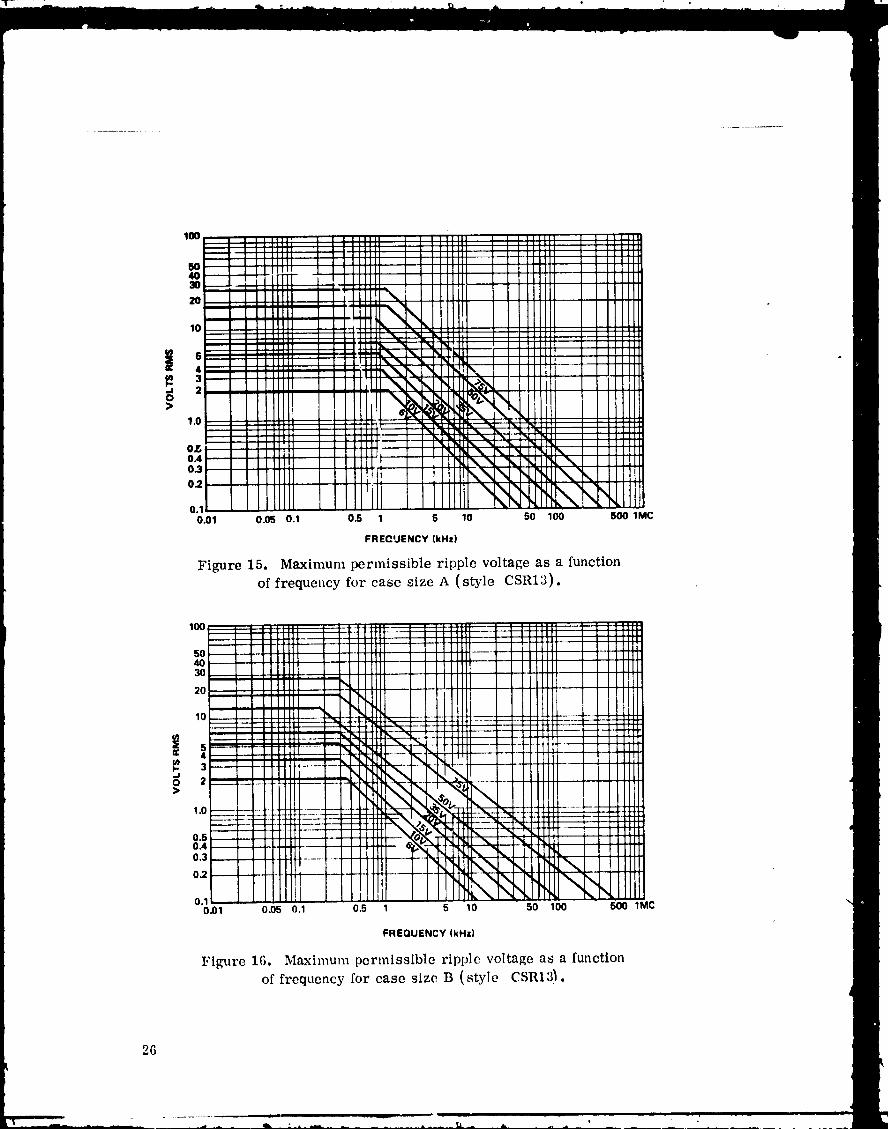
15, Maximum permissibleripplevoltageas a function
offrequencyforcase sizeA (styleCSR13) .......... 26
16. Maximum permissibleripplevoltageas a function
offrequencyforcase sizeB (styleCSR13) .......... 26
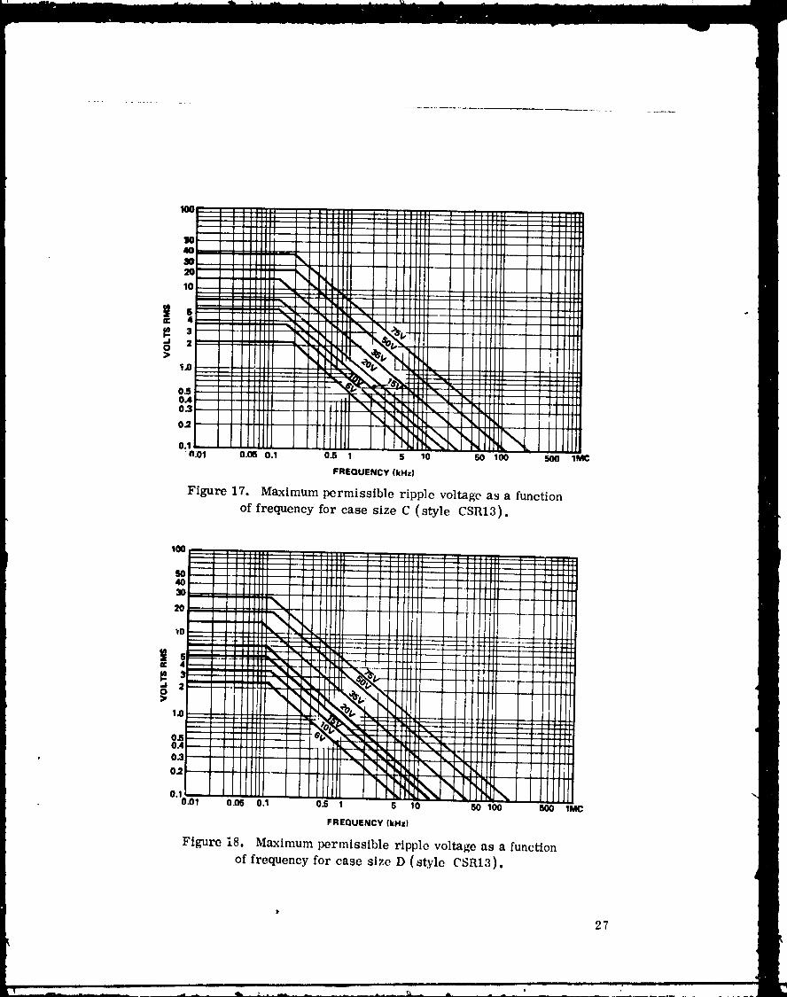
17. Maximum permissibleripplevoltageas a function
of frequencyforcase sizeC (styleCSR15) .......... 27
18. Maximum permissible ripple voltage as a function
of frequency for case size D (style CSR13) .......... 27
19. DC leakage current versus applied voltage for solidtantalum capacitor ........................... 30
20. Failure rate versus temperature .................. 31
21. Maximum recommended voltage spikes for solid
tantalum capacitors .......................... 33
22. Construction features -- wet foil tantalum capacitor ..... 35
23. Effect of frequency on capacitance of typical foil type
tantalum capacitors at 25 ° C .................... 36
24. Impedance curves for tantalum foil capacitors at 25°C... 37
25. Tantalum foil impedance correction factors for
capacitance up to 2/_F 37
26. Tantalum foil impedance correction factors for
capacitance of 2 to 50 _F ....................... 38
vi
] 9780] 0368-006
L!STOFILLUSTRATIONS(Continued)
Figure Title Page
27. Tantalum foil impedance correction factors for
' capacitance of 50 _F and over ................... 38 °
28. Typical curves of impedance with frequency at various
temperatures for 200 _F, 6 V plain foil capacitors ..... 38
29. Typical curves of impedance, capacitance, and ESR with
temperature for 26 #F, 100 V polarized etched foil
capacitors ................................ 39
30. Effect of frequency on dissipation factor of foil type
tantalum capacitors ........................ • 40
31, Typical curve of the ratio of dc leakage current at
rated voltage versus temperature for foil tantalum
capacitors .............................. 40
32. Maximum allowable ripple voltage and current for
styles CLR25, 27, 35, and 37 foil capacitors at60 Hz ................................... 42
33. Correction factor for maximum allowable ripple current
and voltage versus frequency for tantalum foil
capacitors ............................... 43
34. Correction factor for maximum allowable ripple
voltage versus temperature for tantalum foil
capacitors ............................... 43
35. Typical effects of applied dc voltage ot_ failure rate
of foil capacitors ........................... 44
36. Typical effects of temperature on iallure rate nf foil
capacitors ............................... 44
vii
1978010368-007
LISTOFILLUSTRATIONS(Continued)
Figure Title Page
37. Maximum recommended voltage spikes fGr foiltantalum capacitors ......................... 45
38. Construction features -- tantalum cased wet slugtantalum capacitor .......................... 47
39. Effects of temperature on capacitance of CLR79
capacitors (T2 case) ........................ 48
40. Effects of temperature on capacitance of CLR79capacitors (T3 case) ........................ 49
41. Effects of temperature on capacitance of CLR79
capacitors (T4 case) ........................ 49
42. Typical curves of impedance with frequency at various
I temperatures for wet slug 560/_F, 6 V capacitors ..... 5043. Typical curves of impedance with frequency at various
temperatures for wet slug 25 _F, 125 V capacito::s .... 50
44. Effects of frequency on ESR of wet slug capacitors
of various ratings .......................... 51
45. Typical curves of ESR as a function of temperature
for capacitors of various ratings ................ 52
46. Effects of applied dc voltages on dc leakage of CLR79
capacitors ............................... 52
47. Typical T1 case temperature rise as a functionof ripple current ........................... 53
48. Typical T2 case temperature rise as a function
of ripple current ........................... 53
viii
1978010368-008
LISTOFILLUSTRATIONS(Concluded)
, Figure Title Page
49. Typical T3 case temperature rise as a function
, of ripplecurrent ........................... 54 "
50. TypicalT4 case temperatureriseas a function
ofripplecurrent ........................... 54
51. Effectson capacitanceand dc leakageof current-surge
testson CLR79 capacitors..................... 55
ix
1978010368-009

TECHNICAL MEMORANDUM 64755
Rev. A
GUIDELINESFORTHESELECTIONANDAPPLICATIONOFTANTALUMELECTROLYTICCAPACITORS
IN HIGHLYRELIABLEEOUIPMENTo
I. GENERAL
A. Purpose
The purpose of this document is to provide guidelines which supplement
requirements of existing Military Specifications (MIL-SPEC) for tantalum
capacitors used in space flight missions. These guidelines are intended to
optimize the selection and application of these capacitors in space electronichardware.
B. Typesof TantalumCaDacitorsandApplicableMilitary Specifications
Military
Style/Rating Specification
Solid Tantalum CSR09 (6 to 75 V) MIL-C-39003/2
Solid Tantalum CSR13 (6 to 75 V) MIL-C-39003/1
Polarized Etched Foil CLR25 (15 to 150 V} MIL-C-39006/1
Nonpolarized Etched Foil CLR27 (15 to 150 V) MIL-C-39006/2
Polarized Plain Foil CLR35 (15 to 300 V) MIL-C-39006/3
Nonpolarized Plain Foil CLR37 (15 to 300 V) MIL-C-39006/4
Tantalum Cased Wet Slug CLR79 (6 to 125 V) MIL-C-39006/22
Note: MIL-C-39006 covers established reliability styles. Obsolescent
MII,-C-3965 covers similar styles for replacement purposes only.
These specifications give capacitance tolerances, temperature ranges,
etc. Solid tantalum chip style capacitors styles CWR02-08 ,_re omitted
from this document. They are included in MIL-C-55365 and in Section803 of MIL-STD-198D.
1978010368-010
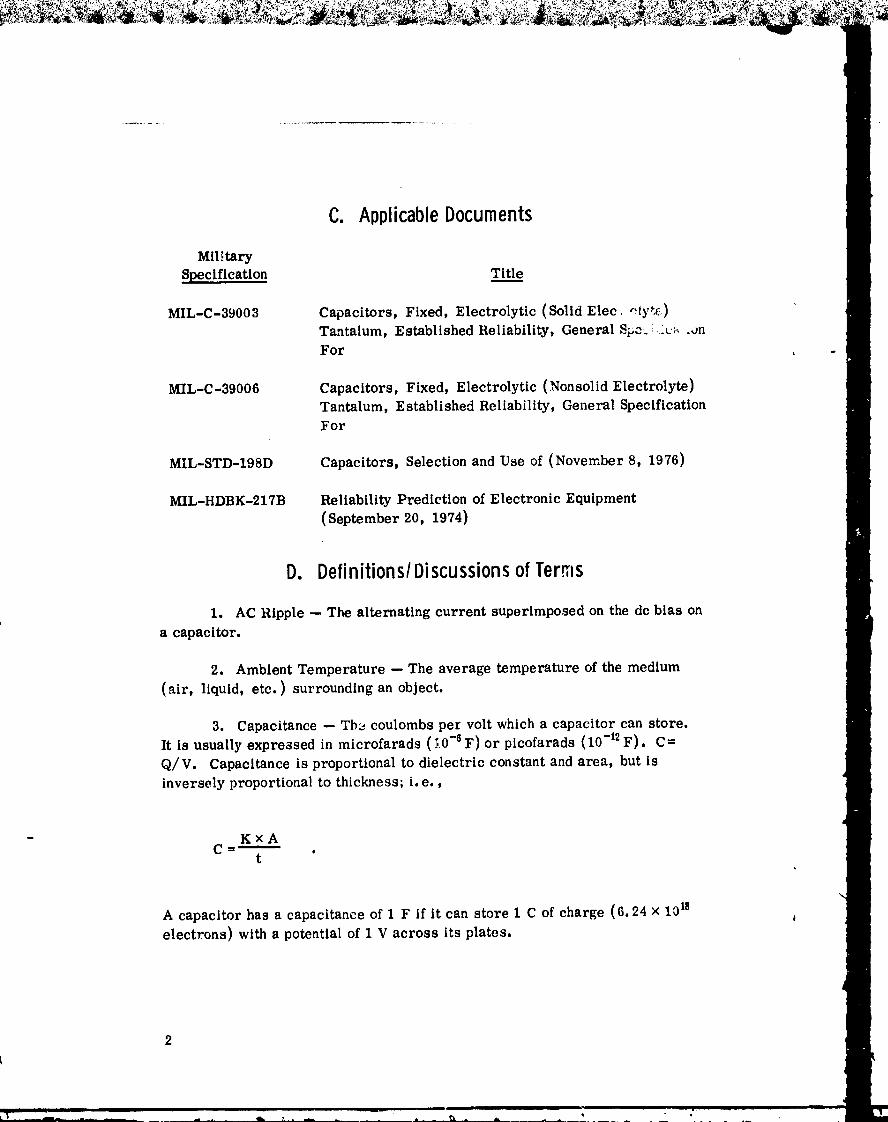
C. ApplicableDocuments
Mll._tary
SpecLflcatlon Titl.___e
MIL-C-39003 CapaciWrs, Fixed, Electrolytic(SolldElec clyde)Tantalum, Established Reliability, General Spo.__._L._.,JnFor , .
MIL-C-39006 Capacitors, Fixed, Electrolytic (Nonsolid Electrolyte)Tantalum, Established Reliability, General SpecificationFor
MIL-STD-198D Capacitors, Selection and Use of (November 8, 1976)
MIL-HDBK-217B Reliability Prediction of Electronic Equipment(September 20, 1974)
D. Definitions/DiscussionsofTerms
1. AC Ripple--The alternatingcurrentsuperimposed on thedc biason
a capacitor.
2. Ambient Temperature --The average_mperature ofthe medium
(sir,liquid,etc.)surroundingan object.
3. Capacitance--Tb_ coulombs pel voltwhich a capacitorcan store.
Itisusuallyexpressedinmicrofarads(_0-eF)or plcofarads(10-12F). C=
Q/V. Capacitanceisproportionalto dielectricconstantand area, but is
inverselyproportionaltothickness;i.e.,
- KxA
t
A capacitor has a capacitance of 1 F if it can store 1 C of charge (6.24 × 10¹⁸electrons)wl_ a potentialof I V across itsplates.
2
L
1978010368-011
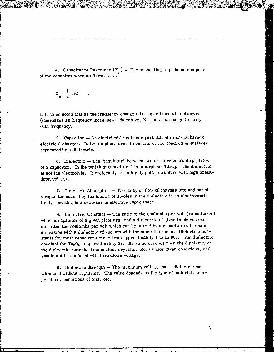
4. Capacitance Reactance (Xc) -- The nonheating impedance componengof the capacitor when ac flows; i.e.,
1X = _Cc 2" "
It is to be noted that as the frequency changes the capacitance also changes
(decreases as frequency increases); therefore, X does not change linearlycwith frequency.
5. Capacitor -- An electrical/electronic part that stores/discharges
electrical charges. In its simplest form it consists of two conducting surfaces
separated by a dielectric.
6. Dielectric -- The "insulator" between t¢o or more conducting plates
of a capacitor. In the tantalum capacitor .' is amorphous Ta20 s. The dielectric
is not the ,,lectrolyte. It preferably ha_ a highly polar structure with high break-
down voI ao :.
7. Dielectric Absorptior. -- The delay of flow of charges into and out of
a capacitor caused by the inertia of dipoles in the dielectric in an electrostatic
field, resulting in a decrease in effective capacitance.
8. Dielectric Constant --the ratio of the coulombs per volt (capacitance)
which a capacitor of a given plate area and a dielectric of given thickness canstore and the coulombs per volt which can be stored by a capacitor of the same
dimension with _ dielectric of vacuum with the same thickne_ s. Dielectric con-
stants for most capacitors range from approximately 1 to 15 000. The dielectric
constant for Ta205 is approximately 28. Its value depends upon the dipolarity ofthe dielectric material (molecules, crystals, etc.) under given conditions, and
should not be confused with breakdown voltage.
9. Dielectric Strength -- The maximum volta,,, that a dielectric can
withstand without rupturing. The value depends on the type of material, tem-
perature, conditions of test, etc.
1978010368-012
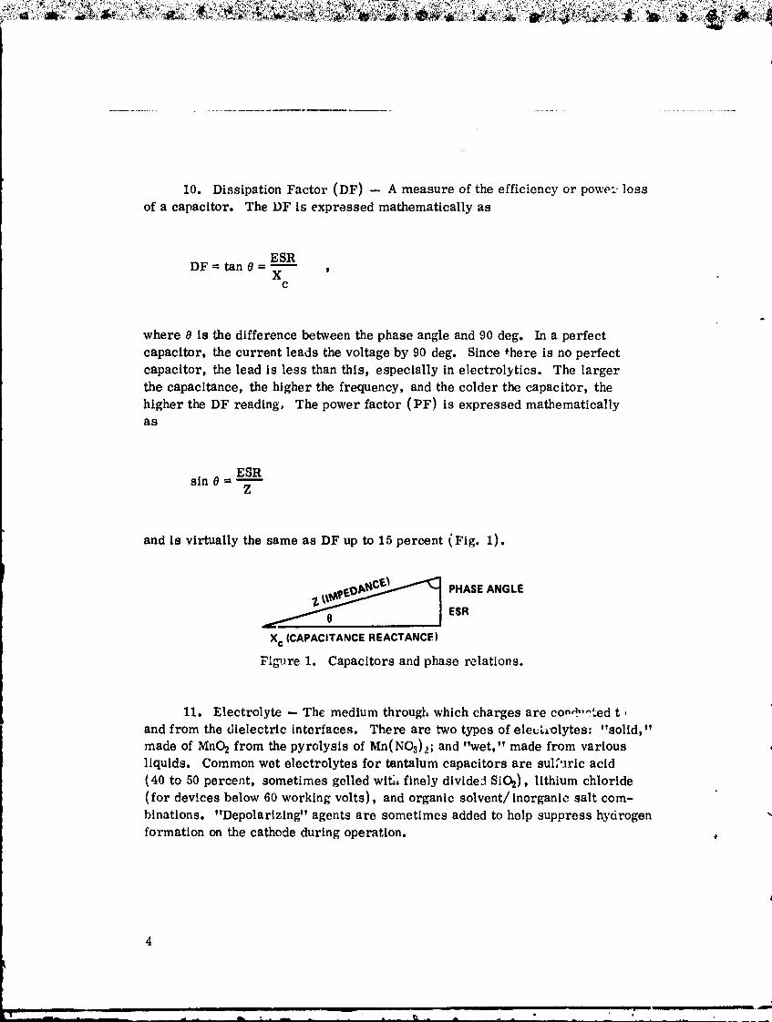
10. Dissipation Factor (DF) -- A measure of the efficiency or power loss
of a capacitor. The DF is expressed mathematically as
ESRDF -- tan _ -
XC
where 8 is the difference between the phase angle and 90 deg. In a perfect
capacitor, the current leads the voltage by 90 deg. Since _here is no perfect
capacitor, the lead is less than this, especially in electrolytics. The larger
the capacitance, the higher the frequency, and the colder the capacitor, the
higher the DF reading. The power factor (PF) is expressed mathematicallyas
ESRsin _ -
Z
and is virtually the same as DF up to 15 percent (Fig. 1).
_/__ PHASEANGLEESR
Xc (CAPACITANCE REACTANCE)
F',_,re 1. Capacitors and phase relations.
11. Electrolyte -- The medium through which charges are co,d-o_ed tand from the dielectric interfaces. There are two types of electrolytes: "solid,"
made of MnO2 from the pyrolysis of Mn(NO,_)_; and "wet," made from variousliquids. Common wet electrolytes for tantalum capacitors are sulfuric acid(40 to 50 percent, sometimes gelled wit/, finely divide_ SiO2), lithium chloride
(for devices below 60 working volts), and organic solvent/inorganic salt com-
binations. "Depolarizing" agents are sometimes added to help suppress hydrogen
formation on the cathode during operation.
4
] 9780] 0368-0] 3

12. Energy Storage -- The amount of energy stored or discharged from
capacitor is usually expressed in joules or microjoules. The expression defining
this value in joules is:
1 QVJ=_ CV2= 2
where C is in farads. For microjoules,
1 CV2ttJ=_
where C is in microfarads. It is to be noted that time is not a factor in these
equations, and the joule value does not depend upon the rate of discharge; i.e.,
1J = 1 watt-seconds
13. Equivalent Series Resistance (ESR) -- The total resistance a capacitoroffers to the flow of ac.ESR decreases with increasing frequency and temperature
up to a point. ESR is +.he "heating component" or "copper loss" in a capacitor
which produces heat (I2R loss) when ac flows. In t},_ tantalum capacitor, the
chief contributor to ESR is the resistance ol the electrolyte. The least resistive
electrolyte is MnO2 in the solid capacitor; the next least resistive is sulfuricacid, then lithium chloride, and then various organic solvent/inorganic salt
solutions. Equivalent series resistance is expressed mathematically as
ESR=X tan0= Z sin 0C
Figure 2 shows where ESR occurs in the equivalent circuit of a capacitor.
t
1978010368-014
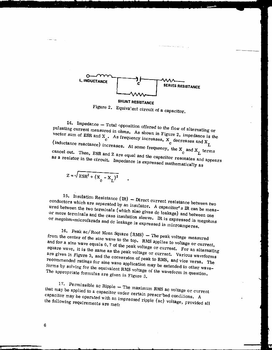
o.._rv'r'r-x _ _AAA-----
L, INDUCTANCE SERI,_SRESISTANCE
SHUNTRESISTANCE
Figure 2. Equivalent circuit of a capacitor.
14. Impedance -- Total opposition offered to the flow of alternating or
pulsating current measured in ohms. As shown in Figure 2, impedance is the
vector sum of ESR and X . As frequency increases, X decreases and X LC C
(inductance reactance) increases. At some frequency, the X and X L termsc
cancel out. Then, ESR and Z are equal and the capacitor resonates and appears
as a resistor in the circuit. Impedance is expressed mathematically as
Z=_/ESR 2+(X c-XL)2 .
15. Insulation Resistance (IR) -- Direct current resistance between two
conductors which are separated by an insulator. A capacitor' s IR can be meas-
ured between the two terminals (which also gives dc leakage) and between one
or more terminals and the case insulation sleeve. IR is expressed in megohms
or megohm-microfarads and dc leakage is expressed in microamperes.
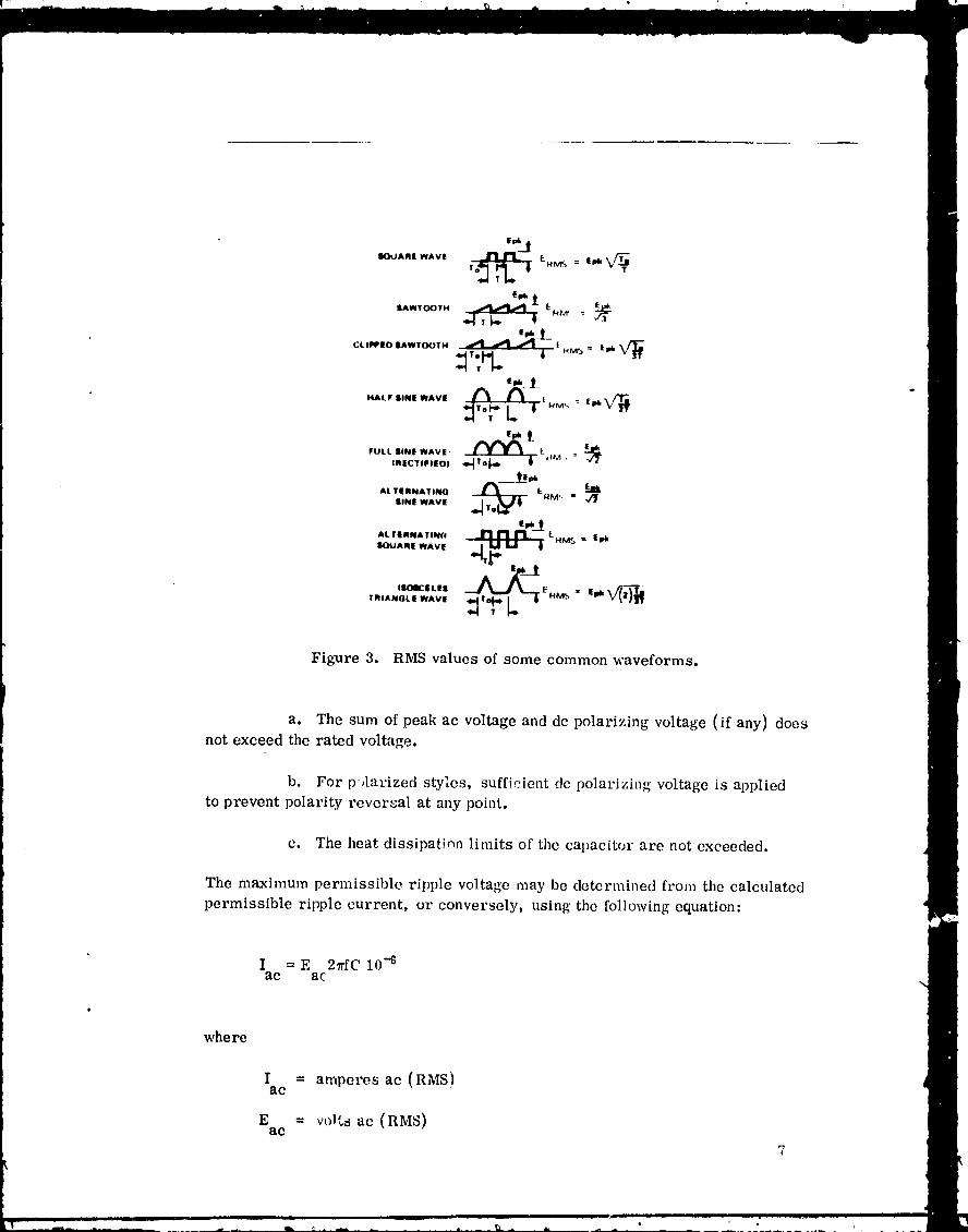
16. Peak ac/Root Mean Square (RMS) -- The peak voltage measured
from the center of the sine wave to the top. RMS applies to voltage or current,
and for a sine wave equals 0.7 of the peak voltage or current. For an alternating
square wave, it is the same as the peak voltage or current. Various waveforms
are given in Figure 3, and the conversion of peak to RMS, and vice versa. The
recommended ratings for sine wave application may be extended to other wave-
forms by solving for the equivalent RMS voltage of the waveform in question.The appropriate formulas are given in Figure 3.
17. Permissible ac Ripple -- The maximum RMS ac voltage or current
that may be applied to a capacitor under certain prescr;bed conditions. Acapacitor may be operated with an impressed ripple (ac) voltage, provided all
the following requirements are met:
1978010368-015
mouAnmw,vl ,o-__ LH_ = E_
IAWIOO_. _ _Hm :
CLIPPEOIAWTO(JTH _| HM5 : E_k
-HALF lINE WAVE t N_ : fpl,
FULL liNE WAVE' __IRECTIFIEOI ,mm_1o _l, Lr{M:' =
&_
ALTERNATING _--"_ I_- _4M," _-_
lINE WAVE _ "
ALTINNATINCl _ LHM S : EJ_UAME WAVE
IlOIEiLll
TRIANGLE WAV. _1_L EHM_ : lPk (_)T_
Figure 3. RMS values of some common waveforms.
a. The sum of peak ac voltage and dc polarizing voltage (if any) doesnot exceed the rated voltage.
b. For p ,larized styles, sufficient dc polarizing voltage is appliedto prevent polarity reversal at any point.
c. The heat dissipation limits of the capacitor arc not exceeded.
The maximum permissible ripple voltage may be determined from the calculated
permissible ripple current, or conversely, using the following equation:
I = E 2vfC 10 -Gae ac
where
I = amperes ac (RMS)ae
E = volts ac (RMS)ac
7
1978010368-016
f = frequency (Hz)
C = capacitance (pF).
This formula is based on X rather than Z, and is therefore approximate.c
18. Plates -- The conducting surfaces of a capacitor adjacent to the
dielectric. One or more plates are positive, and one or more are negative.
The plate may be tantalum foil, a tantalunl slug (made of sintered tantalum
grains), tantalum case, or other materials for the cathode. Technically, a wet
tantalum electrolytic has two capacitors in ser_cso On the anode, the positive
plate is tantalum and the cathode is the electrc]yte; on the cathode, the positive
plate is the electrolyte and the cathode is the case for the slug type and the case
and foil for the foil type. For the solid tantalum, the anode is the slug and the
cathode is MnO2 adjacent to the Ta205 dielectric. The effective series capaci-tance is the product of the anode and cathode capacitance divided by the sum ofthe two.
19. Spike -- A momentary sharp increase and then decrease in voltage/
current [n a circuit (synonymous with transient).
E. GeneralSelect!onGuidelines
1. Determine circuit parameters, such as steady-state dc voltage, peak
dc voltage, peak ac current, waveform (pulse width, repetition rate and rise
time, etc. ) steady-state ac ripple, and frequency. Oscillograms are recom-mended.
2. Determine environmental operating conditions of the circuit: (a)
maximum-minimum operating ambient temperatures, (b) shock, (c) vibration,
(d) humidity, and (e) temperature cycling.
3. Select a capacitor type from F in terms of the previously mentioned
operating requirements and guidelines in this document.
4. Gather and review ttie following technical data from vendor and specs
on the selected capacitor: (a) capacitance and tolerance, (b) capacitance change
over the operating temperature, (c) dissipation factor, (d) DF change over the
1978010368-017
operating temperature, (e) ESR and its change with operating temperature,(f) dc leakage and its change with temperature, (g) insulation resistance, (h)
,_ermissible ac voltage and current at operating frequency, and (il permissible
temperature rise due to ac ripple.
5. Verify that the proposed capacitor is optimum for the application. If
not, repeat the selection process. Given the previously mentioned information,
the applications engineer can usually select the proper capacitor with confidence.
He may indeed find that he cannot use an electrolytic capacitor.
F. PreferredApplicationsGuidelines
Generally, tantalum electrolytics are used in applications requiring high
capacitance per unit volume and weight, with large tolerances. Such applications
include blocking, filtering, bypassing, coupling, and energy storage. When used
in phase shifting circuitst the DF must be taken into consideration. Their use
in pulsing and raw ac applications should be cautious and subject to verificationexperiments for the particular application. These capacitors are preferred to
other types in applications requiring long life and high reliability.
Following are some general guidelines in selecting capacitors for certain
applications. The rationale for these guidelines will be presented later in this
report.
1° Solid Tantalum (CSR09 and 13). The solid tantalum (CSR09 and 13)capacitors are preferred for the following applicatiuns:
a. Circuits which deliver less than 0.33 A to a shorted capacitor.
b. Circuits that do not generate spikes and which, in turn, are not
sensitive to scintillations produced by "self-healing" of the capacitor.
c. Circuits with steady-state peak voltages less than 45 V (up to
85°C).
d, Circuits which are not sensitive to electromotive force (EMF)
generated by the capacitor.
9
1978010368-018

e. Low temperature applications in which high ESR is intolerable and
minimum changes in capacitance, DF, and impedav_;e are desired.
f. High vibration and shock applications (up to 100 g-RMS).
2. Wet Foil Type (CLR25, CLR27, CLR35, and CLR37). These foil
capacitors are the most versatile of the tantalum electrolytics since they areavailable in polar and nonpolar forms and plain and etched foil (up to 300 V).However, they generally have higher dc leakage, DF_ and vG)ume _er microfarad-
volt than do the slug types, and have less stable frequency and temperaturecharacteristics.
The foil type capacitors are preferred for the following applications:
a. Circuits with the possibility of reverse voltage above 3 V (use nonpolar
types).
b. Operating voltages greater than those that can be tolerated by solid
or wet slug tantalums (see voltage ratings under each type).
c. Applications with relatively low vibration levels (below 65 g-RMS).
d. Applicat. -q in which fairly large changes in capacitance with tempera-
ture and high ESR, especially at cold temperatures, can be tolerated.
e. Circuits which can tolerate relatively high dc leakage, in the micro-
ampere range. (When used for low-frequency coupling ill transistor or vacuum
tube circuits, high dc leakage can cause improper positive bias to be appliedacross the grid circuits, or excessive base, emitter, or collector currents. It
should be noted that dc leakage may increase drastically as temperature
increases. )
f. Nonpolar types are primarily suitable for ac applications or where dc
voltage reversals occur, such as in tuned low-frequency circuits, phasing of
low voltage ac motors, in computer circuits in which dc voltage reversal occurs,or in servo systems.
3. Tantalum Cased Wet Slug (CLR79). The tantalum cased wet slug
(CLR79) capacitor is preferred for the following applications: °
10
1978010368-019
a. High ripple current applications such as in power supply and bLs
filtering.
b. Low dc leakage applications, such as timing circuits.
c. Circuits which produce spikes and transients.
d. High in-rush current applications, such as input filtering.
e. Applications requiring up to 3 V reverse bias.
Note: Wet slug capacitors using cathode cases other than
tantalum are not recommended for flight purposes.
G. RecommendedFailure RateLevels
Failure rate levels P, R, and S (0.1, 0.01, and 0.001 percent/1000 h
failure rate respectively, all at a 60 percent confidence level) are recommended.Failure rates L and M are not recommended.
Rationale
Failure rate levels L and M do not include sufficient test data or offer
enough evidence of product maturity for high reliability space hardware. Failure
modes are opens, shorts, intermittents, and parameter drift (capacitance, ESR,
impedance, and dc leakage).
H. RecommendedTemperatureRanges
These electrolytic capacitors can operate safely over a range of -55 to
125"C. Because of hermetic seals, these capacitors should operate at 85°C for
at least 10 000 h at full rated voltage without serious deterioration. Derating is
required above 85 ° C.
I. HermeticSeals
It is recommended that all tantalum capacitors be hermetically sealed.
11
1978010368-020
Rationale
Nonsolid (wet) electrolyte tantalums may lose electrolyte in the vacuum
of space or on Earth. These electrolytes are corrosive and will attack othercomponents on the PC board and may cause high dc leakage. Solid electrolytic
capacitors which are not hermetically sealed can absorb moisture prior tolaunch and can subsequently deteriorate in space due to parameter drifts. Thesehermetic seals also permit virtually no limit to thermal cycling, and with no
fear of electrolyte leakage.
J. GeneralElectricalCharacteristics
1. To minimize inductance effects at higher frequencies, the use of
slug type capacitors rather than foil types is recommended.
2. Maximum applied steady-state dc voltage should be no more than 60
percent of rated dc voltage at the respective temperatures up to 85°C and from
85°C to 125°C. The greater the derating, along with the use of physically
smaller units, the more likely the following bcneflts will be achieved:
a. Lower dc leakage due to thicker oxide dielectric.
I b. Lower ESR and DF.
c. Lower production of gaseous hydrogen on wet types.
d. Greater stability of dc leakage, ESR, DF, _F, and Z over the
operating temperature range.
e. Better tolerance to spikes and transients due to a thicker oxide.
K. DielectricAbsorption
It is recommended that the design engineer understand the effects of
dielectric absorption on capacitance changes at different frequencies and the
effects of residual charges on the capacitor that may affect the circuit.
12
1978010368-021
Rationale
Dielectric absorption (already defined) is an unfortunate characteristic
of all capacitors. It is probably the least understood of capacitor problems.
Dipoles in the dielectric require a finite time to orient themselves to the applied
field. They also have certain relaxation moments and do not return to their
previous orientation the moment the field is removed. Therefore, the charging
or discharging of a capacitor is never complete, but is asymptotic. Electronstend to behave In the dielectric as though some were "free, 'v and others V_ound. Tv
The practical result of this phenomenon is that as the frequency of the ac
increases the electrons appear to be more and more bound, or "absorbed,"
and capacitance decreases. However, since ESR (the heating component)decreases as frequency increases, design engineers would do well to select
frequencies for power supplies in the 10 to 20 kHz range rather than at lower
frequencies, even though there is capacitance loss. The engineer must constantlybear in mind that the rating of capacitance, DF, ESR, and impedance are basedon measurements taken at 120 Hz, and that these parameters may vary consider-
ably from the 120 Hz reading when measured at other frequencies. Dielectric
absorption is often a major factor in this variation.
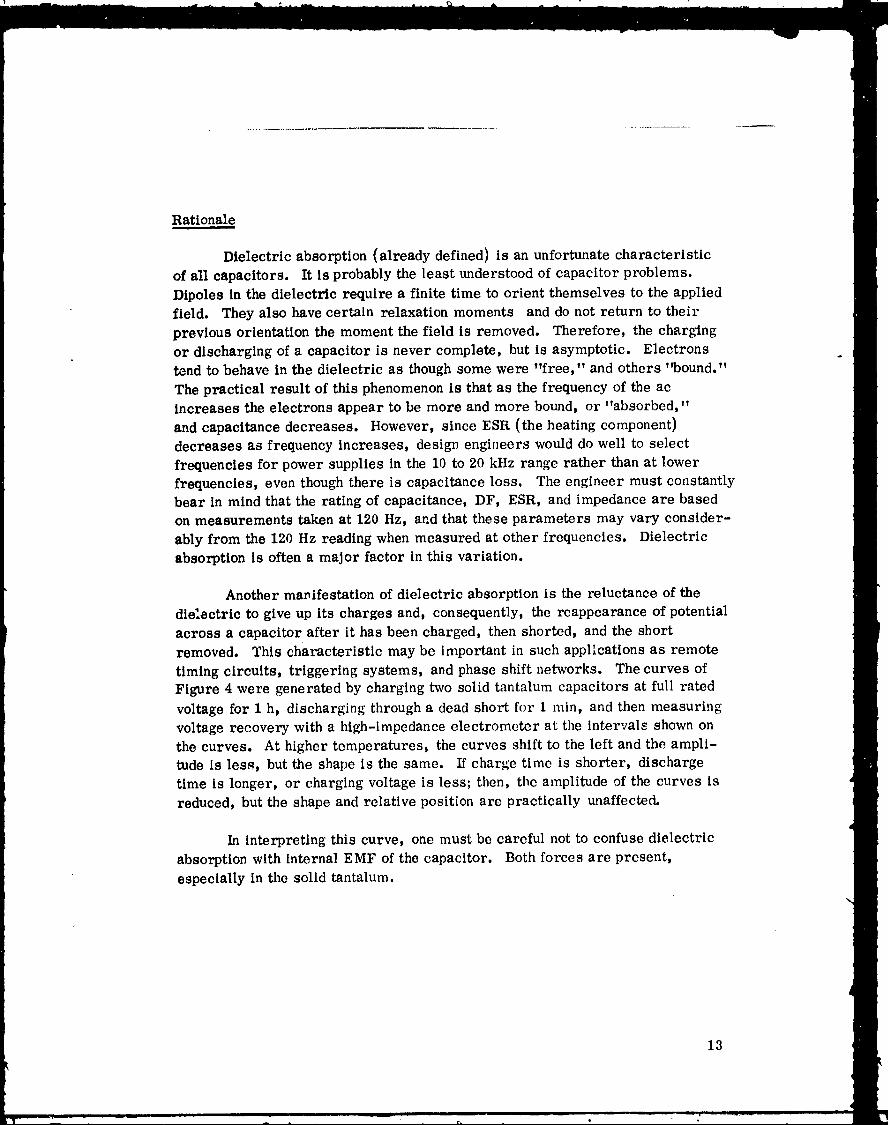
Another manifestation of dielectric absorption is the reluctance of the
die'.ectric to give up its charges and, consequently, the reappearance of potential
across a capacitor after it has been charged, then shorted, and the short
removed. This characteristic may be important in such applications as remote
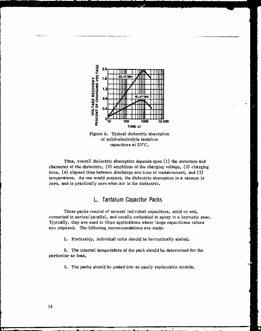
timing circuits, triggering systems, and phase shift networks. The curves ofFigure 4 were generated by charging two solid tantalum capacitors at full rated
voltage for 1 h, discharging through a dead short for 1 rain, and then measuring
voltage recovery with a high-impedance electrometer at the intervals shown on
the curves. At higher temperatures, the curves shift to the left and the ampli-tude is less, but the shape is the same. If charge time is shorter, discharge
time is longer, or charging voltage is less; then, the amplitude of the curves is
reduced, but the shape and relative position are practically unaffected.
In interpreting this curve, one must be careful not to confuse dielectric
absorption with internal EMF of the capacitor. Both forces are present,
especially in the solid tantalum.
13
1978010368-022
w
20 IIll,tilIX I,IIIIIII_dIIIIIIIIIIIIII
_ IIIIIII/IIIIIIIIIIIIIIII1.2_,,,- IIIIUI"IIIIIIIII II11111='_ II_! I '_."_' IIII III_: o., ,tllllll _ IIII111
_ .,_l I lilllli",l ill 11,_.., 0.4,,J,, IIIII [ I lllllll IIII III>_ v IIIIIII I IIIIIII1 I llllll' w 010 100 1000 10000.o.
TIME(;)
Figure 4. Typical dielectric absorption
of solid-electrolyte tantalum
capacitors at 25"C.
Thus, overalldielectricabsorptiondependsupon (1) thestructureand
characterofthedielectric,(2) amplitudeofthechargingvoltage,(3) charging
time, (4) elapsedtime between dischargeand time of measurement, and (5)
temperature. As one would suspect,thedielectricabsorptionina vacuum is
zero, and ispracticallyzerowhen airisthedielectric.
L. TantalumCapacitorPacks
These packs consist of several individual capacitors, solid or wet,
connected in series/parallel, and usually embedded in epoxy in a hermetic case.
Typically, they are used in filter applications where large capacitance valuesare required. The following recommendations are made:
1. Preferably, individual units should be hermetically sealed.
2. The internal temperature of the pack should be determined for the
particular ac load.
3. The packs should be potted into an easily replaceable module.
14
1978010368-023

Rationale
1. Leaking electrolyte may cause high dc leakage, production of hydro-
gen, high internal pressure, and even rupture of the case (in case of wet types).If nonhermetic units are used, all anode connections should be made of heavytantalum wire or ribbon, which would "form" in case of contact with electrolyteand thus minimize dc leakage. The use of CLR79 capacitors provides maximum
CV product per unit volume, low dc leakage, and overall high reliability. In all
cases the pack must be hermetically sealed.
2. The plastic encapsulant in the package does not dissipate heat well,and the applications engineer should know the internal temperature. This can be
determined by inserting a thermistor or thermometer into the center of the packwhile the plastic is molten and conducting the test after the plastic sets.
3. Sometimes all tbe packs are potted into a module for massive filtering
purposes. If a pack fails, it is difficult to remove it by depotting. Therefore,potting should be done in such a way as to reduce cost and effort in making aretrofit.
M. Mounting
It is recommended that capacitors be mounted in such a manner that the
body _nd not the lead wires are subjected to stresses such as vibration and shock.
Rationale
The lead wires are relatively small and may break during flight stresses.
Also, they are encased in glass at least on one end, and stresse_ on the glass
may shatter it and permit electrolyte to leak. Thus, plastic or band body
mounting is recommended.
N. Destructiveor FailureAnalysisofWetTypes
It is recommended that the capacitors be opened with care during any
analysis.
15
1978010368-024

Rationale
The electrolyte may be under some pressure; therefore, it may squirtol,t and contact personnel or equipment and cause damage because of its corrosive
nature. Generally, the electrolyte for tantalum slugs has approximately a 40percent concentration of sulfuric e,_id. For foil types, a commonly used electrolyteconsists of dimethylfo,'mamide/ethylene glycol as solvents, with some salt such
as potassium thiocyanate.
No single detection method is adequate for all electrolytes; therefore,
the composition of each electrolyte must be determined and effective testingmethods devised. If it is known that the electrolyte is acidic, then blue litmus
paper moistened in deionized water is an effective and sensitive test for detectingthe presence of acid. However, care must be exercised to ensure that foreign
substances such as soldering fluxes and body acids are not present, as this would
result ill a false positive test. If the electrolyte is neutral (pH 7) or its composi-tion is unknown, a fine leak test per MIL-STD-202 may be used to check her-
meticity of the case and a possible leakage of the electrolyte.
O. Construction
In all types of tantalum capacitors, the anode riser wire should extend
not moze than O. 25 in. beyond the glass seal, and the external lead welded to
the riser should be of adequate length to permit bending, insertion, and soldering
in a PC board without compromising the weld integrity.
P. ControlofForwardandReverse
VoltageonWetTyDes
It is recommended that voltage deratlng be used as stated under each
type as a reliability consideration. It is also recommended that forward andreverse biases not exceed the rated levels.
Rationale
Hydrogen gas may form on one of the electrodes, build up internal
pressure, and cause the device to explode. This can be hazardous to both
personnel and equipment.
16
m-- __ i] __
i m
1 7Rnl
Q. BarometricPressure
Since these capacitors are hermetically sealed and do not operate at high
voltage, therp is no problem in operating them in the vacuum of space. Theywill also tolerate pressures above 1 atm (29.9 in. of Hg or 760 mm), dependingon size of case. The smaller cases tolerate a higher pressure, and the solid
tantalum will withstand a higher crush strength than will the wet types. Generally,
these capacitors will withstand at least 10 atm without a problem.
R. Radiation
Electrolytics may undergo parameter changes from either ionizing or
burst radiation, depending on dosage. The dielectric can be weakened, and dc
leakage may rise as a result of bombardment. Unfortunately, tantalum itself
has a heavy nucleus and can absorb neutrons readily. Therefore, caution is
urged in using these capacitors in radiation fields (including solar flares} on
space missions. Teflon parts used inside the capacitor also undergo marked
degradation when bombarded with radiation, especially in the presence of
oxygen.
S. Series-ParallelApplications
If capacitors are hooked in series to permit higher voltage application,a shunt resistor should be hooked across each unit to prevent the capacitor with
the lowest dc leakage from having the dc voltage across it too high. For parallel
application in which the total capacitance equals the sum of the individual capaci-
tances, two precautions should be observed. First, the rules regarding dc
voltage and ac ripple levels given in Paragraph I. D item 17 should be observedas in the case of individual units. Furthermore, the connecting leads of the
parallel network should be large enough not to increase ESR and DF.
17
1978010368-026
II. SOLIDTANTALUMCAPACITORS
The following recommendations and comments apply to all solid (CSR)type tantalum electrolytic capacitors.
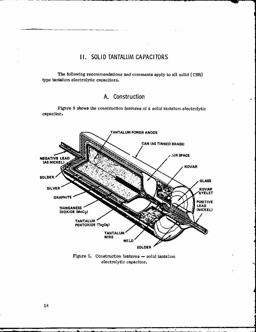
A. Construction
Figure 5 shows the construction features of a solid tantalum electrolyticc_,pacitor.
TANTALUM POWERANODE
CAN (AS TINNED BRASS)
NEGATIVE LEAD / ._IR SPACE(AS NICKEL
KOVAR
SOLDERGLASS
SlLVER KOVAR_YELET
GRAPHITEPOSITIVELEAD
MANGANESE (NICKEL)
DIOXIDE (MnO2) /TANTALUMPENTOXIDE {Ta2Os)
TANTALWIRE
WELD
SOLDER
Figure 5. Construction features -- solid tantalumelectrolytic capacitor.
18
T " • ' •
1978010368-027
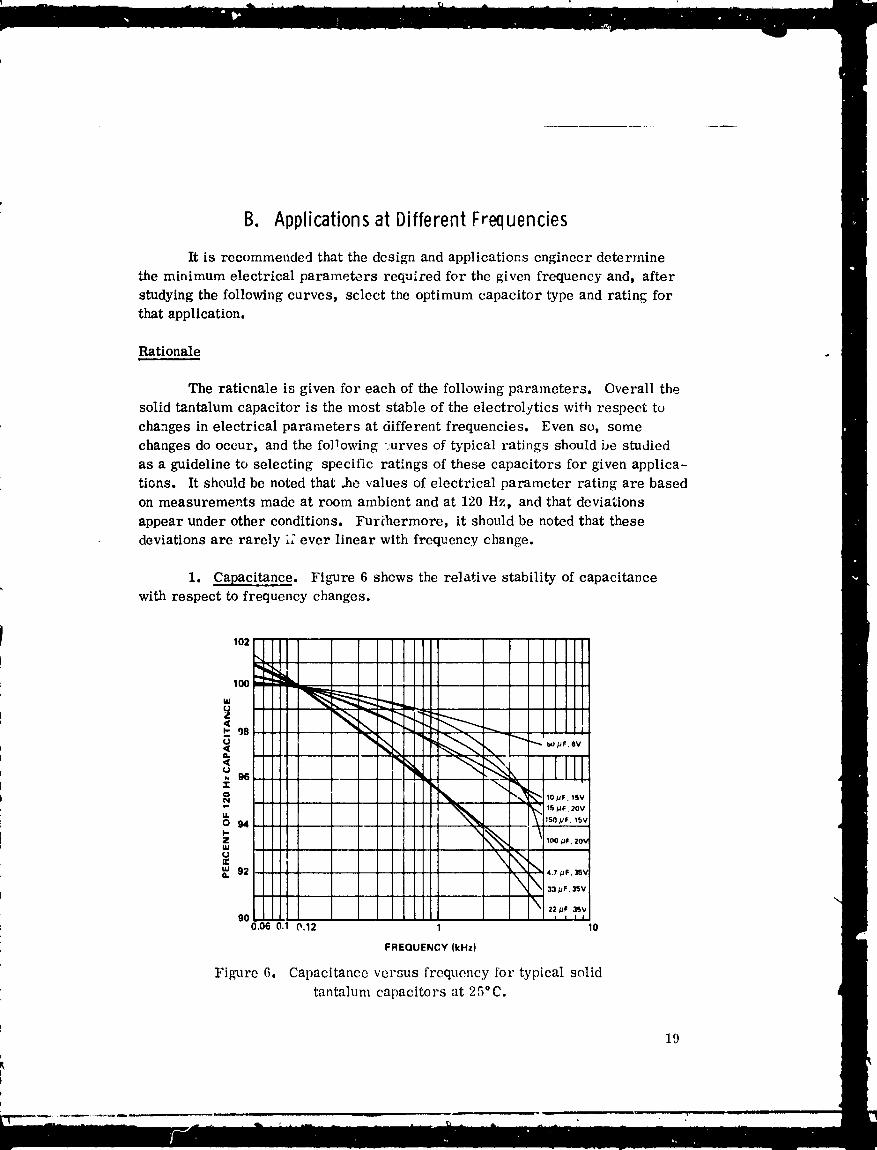
B. Applicationsat Different Frequencies
It is recommended that the design and applications engineer determine
',,he minimum electrical parameters required for the given frequency and, after
studying the following curves, select the optimum capacitor type and rating forthat application.
Rationale
The raticnale is given for each of the following parameters. Overall the
solid tantalum capacitor is the most stable of the electrolytics with respect to
changes in electrical parameters at different frequencies. Even so, some
changes do occur, and the following ;urves of typical ratings should be studied
as a guideline to selecting specific ratings of these capacitors for given applica-
tions. It should be noted that .he values of electrical parameter rating are based
on measurements made at room ambient and at 120 Hz, and that deviations
appear under other conditions. Furihermore, it should be noted that these
deviations are rarely ;; ever linear with frequency change.
1. Capacitance. Figure 6 shows the relative stability of capacitancewith respect to frequency changes.
102
_,100
N 9611:o
IL
I-Z
UOC
_ 92
gO0.06 0.1 0.12 1 10
FREQUENCY (kHz)
Figure 6. Capacitance versus frequency tot" typical solid
tant.'_lum capacitors at 25°C.
19
--vi
1978010368-028
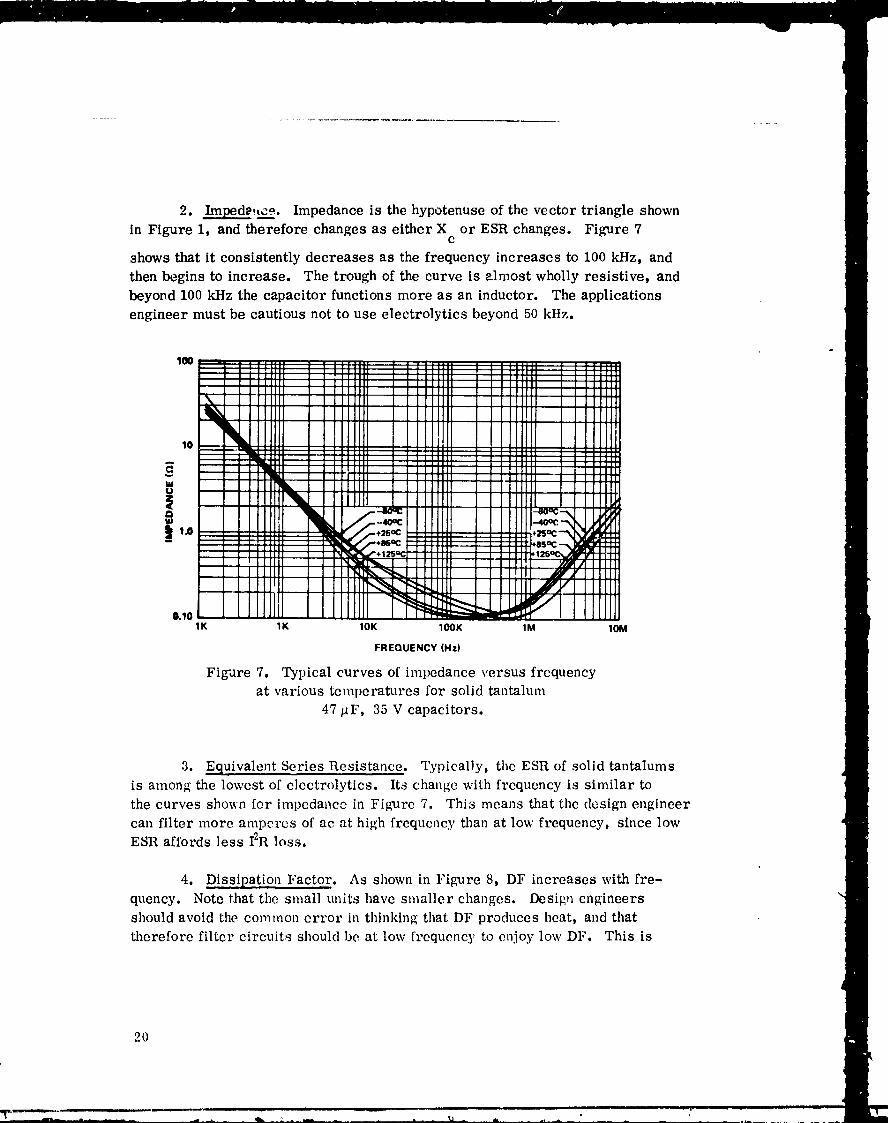
2. ____ped_,Lce. Impedance is the hypotenuse of the vector triangle shownin Figure 1, and therefore changes as either X or ESR changes. Figure 7c
shows that it consistently decreases as the frequency increases to 100 kHz, and
then begins to increase. The trough of the curve is almost wholly resistive, and
beyond 100 kI-Iz the capacitor functions more as an inductor. The applications
engineer must be cautious not to use electrolytics beyond 50 kHz.
10
W
Qua
0.101K 1K 1OK lOOK 1M 10M
FREQUENCY (Hz)
Figure 7. Typical curves of impedance versus frequency
at various temperatures for solid tantalum
47 gF, 35 V capacitors.
3. _uivalent Series Resistance. Typically, the ESR of solid tantalums
is among the lowest of electrolytics. Its change with frequency is similar to
the curves sho_n for impedance in Figure 7. This means that the design engineer
can filter more amperes of ac at high frequency than at low frequency, since lowESR affords less I2R loss.
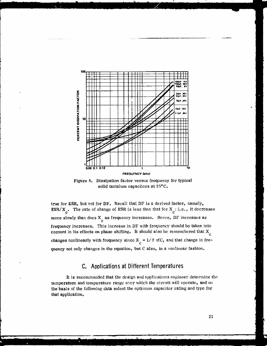
4. Dissipation Factor. As shown in Figure 8, DF increases with fre-quency. Note that the small units have smaller changes. Desig,_ engineers
should avoid the common crror in thinking that DF produces heat, and that
therefore filter circuits should be at low frequency to enjoy low DF. This is
2O
1978010368-029
100
10.06 0.1 0.12 1 10
FREQUFNCY (kHz)
Figure 8. Dissipation factor versus frequency for typical
solid tantalum capacitors at 25°C.
true for ESR, but not for DF. Recall that DF is a derived factor, namely,
ESR/X . The rate of change of ESR is less than that for X : i.e., it decreasesC C
more slowly than does X as frequency increases, ttence, DF increases asc
frequency increases. This increase in DF with frequency should be taken into
eccount in its effects on phase shifting. It should also be remembered that Xc
changes nonlinearly with frequency since X = 1/2 vfC, and that change in fre-c
quency not only changes in the equatio,1, but C also, in a nonlinear fashion.
C. Applicationsat Different Temperatures
It is recommended that the design and applications engineer determine the
temperature and temperature range over which the circuit will operate, and on
the basis of the following data select the optimum capacitor rating and type for
that application.
21
1978010368-030

Rationale
This recommendation is made for two reasons: (1) the change in elec-trical parameters experienced as temperature changes, and (2) the increase infailure rate as temperature increases.
Tempem.ture variations affect capacitor parameters primarily becauseof changes in conductivity of the electrolyte and the changes in dielectric constant.
In addition to their relative stability over a wide range of frequency, the
solid tantalums are also relatively stable over a wide temperature range withrespect to capacitance and DF, but less for ESR, and even less so for dc leak-
age. All parameters fare well at low temperatures because the solid electrolyteis a semiconductor and does not depend on ionic conduction as do the wet electro-
lytes, Therefore, one would expect ESR and related parameters to remainfairly stable.
Cold temperatures reduce ionization and ionic mobility of the wet types;
therefore, one would expect the solid tantalums to exhibit rather outstandingtemperature characteristics. The somewhat unpredictable values for ESR
are doubtless caused by the changes in the contact resistance of the many inter-faces in this capacitor and not necessarily to changes in the MnO2 itself.
1. Impedance, Capacitance t and Series Resistance. Typical curves of
impedance, capacitance, and ESR versus temperature are shown in Figures 9through 12.
Figure 9. Typical curves
of impedance, capacitance, ,_ EOUIVALENTSERIESRESISTANCE j
and ESR versu'_ tempera- o __'__ _NClEture for 330/_F, 6 V _ 1_ _ /
-80 -50 -25 0 +25 +50 +75 +100 +125TEMPERATURE (°C)
2.0
Figure 10. TypLcal curves
of impedance, capacitance, _ IMPEDANCE
and ESR versus tempera- ._ "'"'-.m qm' _'1 ' "ram _ al •
ture for 68/_F, 20 V o 1.0 ;..._,,_ _ _--'-- -----.-.----'- -'-capacitors. :_ o_°_CAPAO
.TANCE' _EQUIVALENTSEIneSRESUSTANCE"_ -0.7
-80 -50 -25 0 +26 +50 +75 +100 +12BTEMPERATURE (_C)
22
1978010368-031

Figure 11. Typical curvesN "
of impedance, capacitance, _ o_1_ ---.and ESR versus tempera- _ o_
O- 0.7ture for 6.8 _F, 35 V
< 0.6
capacitors.0iS
0.4
0.3--80 --50 --25 0 +25 +50 +75 +100 +125
TEMPERATURE (°C)
2.0i
iIMPEDANCE
Figure l2. Typical curves _ ...........of impedance, capacitance, l_ _ - _ --
i,- 'mR_'e q"P _it _ _..i/• •
and ESR versus tempera- _ 1_ __0.g ..... ,_. ,,- _v _ ...... ,,,
ture for 47 _F, 35 V o o_ -C_APACiTANCE J0.7 _'_capacitors. _ / _._0.6
f0.5
0.4 "_UIVALENT _ERIES RE$ISTfNCE-80 -50 -25 0 +25 +50 +76 +100 +126
TEMPERATURE (°C)
2. DC Leakage. Unfortunately, higher temperatures cause dc leakageto increase rapidly; consequently, its value may be fifty times as much at 125°Cas it is at room ambient. These values vary from capacitor to capacitor and
depend upon the integrity of the Ta205. Not only is this true, but dielectricpuncture and catastrophic failure are much morc likely to occur at elevated
temperatures. The engineer may largely circumvent these problems by deratingthe steady-state dc voltage (Paragraph II. F).
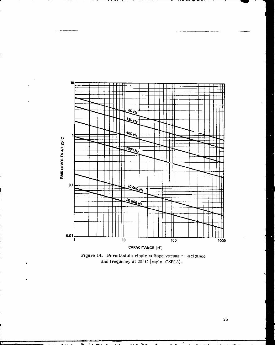
D. PermissibleacVoltageandCurrent
It is recommended that the applications engineer determine the peak and
steady-state ac voltage and current which the capacitor in each application will
experience and select from the following curves a capacitor which meets the
requirements.
23
1978010368-032

Rationale
The solid tantalum capacitor is essentiall_ a dc device and is not as well
suited to hamJ_ing ac as are the wet types. Applications in which the capacitoris subjected to repetitive charge/discharge cycles (especially where the source
impedance is low) can produce severe stress on the dielectric. Energy storageand pulse forming applications often fall into this category, as do filter networks
in which the superimposed ac ripple may be excessive. Figures 13 through 18e
can serve as guidelines in these applications.
10
gP
t"
_JO>t)q
0.11 10 _00 1000
CAPACITANCE (/JF) d
Figure 13. Permissible ripple voltage versus capacitanceand ambient temperature at 120 Hz (style CSR13).
d
As previously stated, the reason that the capacitor can carry more ac
ripple current at high frequency is because the ESR is less, and therefore I2R
loss is less. However, a small capacitor is proportionately a better heat sink
per microfarad-volt than is a larger capacitor because of the relatively great
surface area exposed to the ambient.
In all cases, the guidelines for limiting ac ripple previously stated inParagraph I. D item 17 must be met.
24
i iio_ m_ m la
1978010368-033
10
1cJo
p..Jo>
O_
Im
0.1
0.011 10 100 1000
CAPACITANCE(/JF)
Figure 14. Permissible ripple voltage versus _ ,acitance
and frequency at 25°C (style CSR13).0
25
i, _ _ ii _ i • __ •
1978010368-034
100
604030
2O
10
j .O>
1.0
0AO.3
O2
0.10.01 0.05 0.1 0.5 1 5 10 50 100 500 1MC
FREQUENCY (kHz)
Figure 15. Maximum permissible ripple voltage as a functionof frequency for case size A (style CSR13).
30
20
10
I-,,J
1.0 "
0.50.40.3
02 "
0.10.01 0.05 0,1 0.5 1 5 10 50 100 500 1MC
FREQUENCY (kHz)
Figure 16. Maximum permissible ripple voltage as a functionof frequency for case size B (style CSR13_.
26
1978010368-035
10
i!O.SO.4
O2
n.01 0.06 0.1 0.5 1 5 10 50 100 500 1MC
FREQUENCY(kHz)
Figure 17. Maximum permissible ripple voltage as a function
of frequency for case size (2 (style CSR13).
_00 i , ,
"10 .
!
0A
, 0.302
0.0.01 0.05 0.1 0.5 1 5 10 50 100 500 1MC
FREQUENCY(kHz)
Figure 18. Maximum permissible ripple voltage as a functionof frequency for case size, D (style CSItl3).
$
27
1978010368-036
E. TemperatureRiseLimitationDuetoacRipple
Temperature rise due to self-heating should be limited to 5*C. It isfurther recommended that when capacitors must be operated at conditions out-side the MIL-SPEC recommendations, the temperature rise be measured in the
actual application.
Rationale
The rate of degradation is a function of temperature. The maximum riseof 5°C above the ambient has been chosen as an economic compromise. Heating
is the result of I2R losses, where the current component (I) is from repetitive
charge-discharge cycles or ac ripple voltages and is, therefore, a function of thewaveform (Paragraph L F item 17); and the resistance component (R) is the ESR,which decreases with increasing frequency. Cooling is a function of case sizeand conduction and convection paths. Generally, convection paths are not avail-
able in space applications.
F. Dielectric Protection
It is recommended that the solid tantalum capacitor not be used in
appllcation_ in which a high inrush of current can occur (such as in the input
capacitor of power supply filters) and that necessary measures be taken to
protect the dielectric from puncture or other deterioration.
Rationale
F very electronic part seems to have an "Achilles heel." For the solidtantalum capacitor, the paramount problem is that its dielectric is prone to
deterioration and even puncture during "turn-on" or high inrush of current.Unlike the wet types, the soD-' is especially susceptible to failure due to high
dc leakage or shorts due to dielectric deterioration caused by current surges.
The primary failure mode is a catastrophic short due to dielectric
puncture. The failures are somewhat unpredictable with respect to both steady-
state voltage and spikes (particularly the latter). A discussion of three stepswhich can al]evtate this problem is given in the following paragraphs.
28
1978010368-037
1. Select Appropriate Capacitor. Select capacitors which are ratedunder 75 Vdc because the Taro 5 dielectrl_ is "formed" electrolytically or, the
tantalum at 2 to 4 times rated voltage to give added protection to it during
pyrolysis of the Mn(NO3)2 to produce the MnO2 coat. There is a limit to the
forming voltage of any metal before scintillations occur. When tantal, m is
formed lp phosphoric acid, as it usually is, these scintillations begin to appearabove approximately 250 V, depending on temperature, concentration of the acid,purity of tantalum powder in the slug, current density, etc. Thus, since eachscintillation creates an irreversible malignancy in the dielectric, care should be
exercised to prevent it. For these reasons, slugs formed above 250 V (andrated above 75 V) should not be used in space h_rdware.
2. Derate Voltage and Temperature. Applied voltage should not exceed60 percent of the rated voltage at 85°C and 1250C. As an example, for a capaci-tor rated at 75 Vdc (th_ highest voltage recommended), the maximum applied
volta_.'e should be 45 Vdc up to 85°C and 30 Vdc from 85°C to 125°C. If highervoltages are required for a particular application, the use of a foil or wet slugcapacitor is recommended.
This derating achieves three desirable ends. First, it automaticallylowers the limit on ac ripple; second, it decreases the steady-state stress on
the dielectrL.; and third, it makes puncture due to spikes less likely. If thedielectric were perfectly homogeneous, derating wo,_'ld be less urgent. But, it
should be understood that when pyrolysis of Mn(NO3) 2 occurs, quite corrosiveoxides of nitrogen are produced, and these gases weaken the dielectric in spotsat 250OCo These pinpoint defects are not entirely removed when the slugs are
"rehealed" in electrolyte after pyrolysis. Scintillations may occur at these
points during subsequent processing or in use. To aggravate this situation isthe fact that MnO2 is a semiconductor, and is less forgiving of spikes and highervoltages than are the wet electrolytes, especially at higher temperatures.
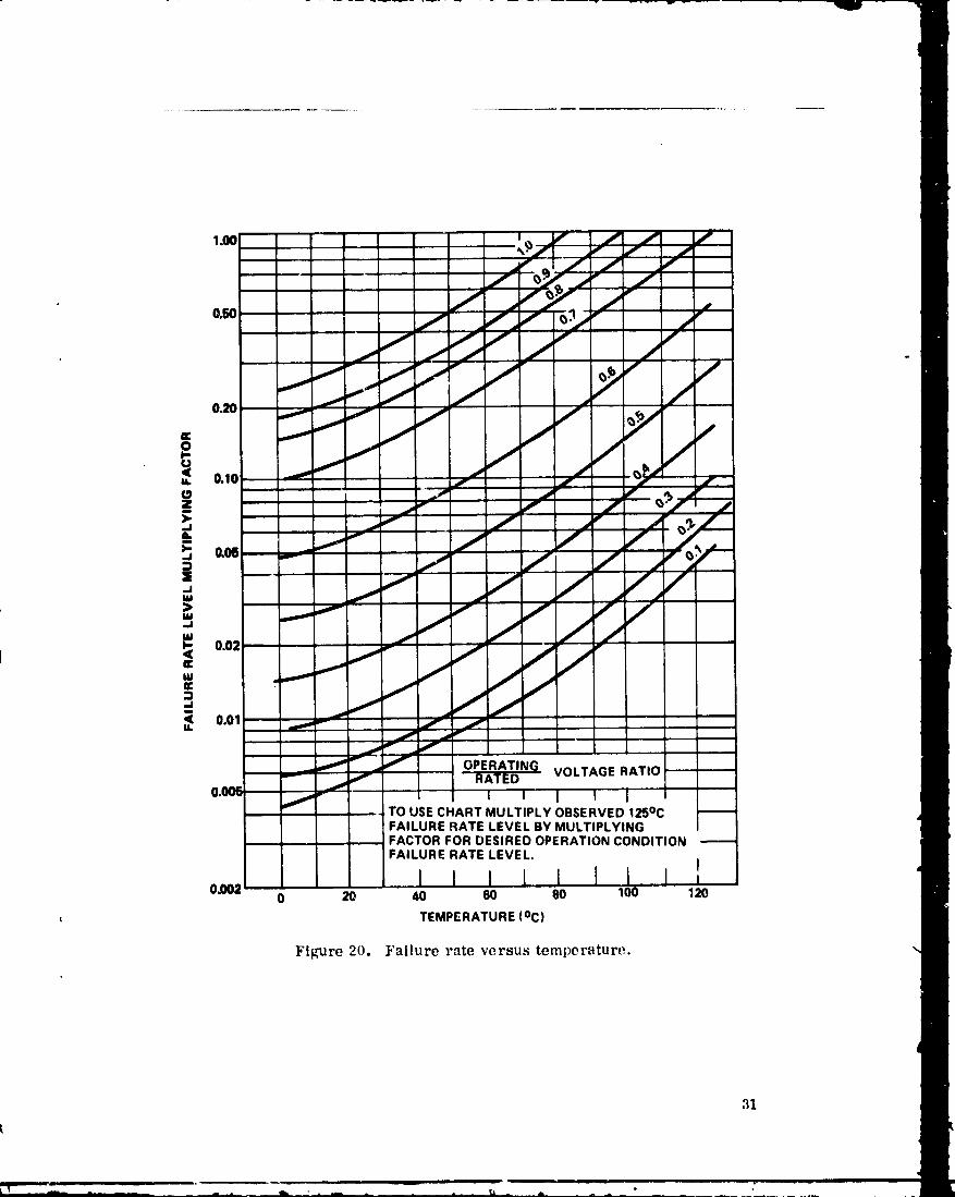
Figures 19 and 20 show how dc leakage and failure rate increase greatly astemperature and voltage increase, Temperature bas a profound effect on dcleakage and failure rate as shown in Figures 19 and 20. Ir,sofar as possible,
means should be used to operate the capacitor at moderate temperatures. This
may mean heat sinking, cooliag by forced air, distribution of parts on the PCboard to avoid proximity to hot devices such as power transistors, careful con-trol of Re ripple levels, and related measures.
29
19780i0368-038
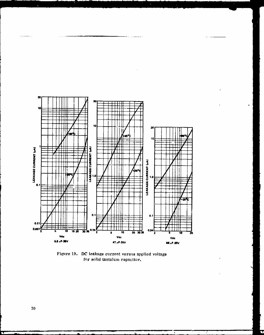
Figure 19. DC leakage current versus applied voltagez
for solid tantalumcapacitor.
3O
1978010368-039
/ i _>Yo.. i /._ o_i _j I
i., --- /i/i_/}I! o.. _ I Ill
0.01 I
_j OPERATING VOLTAGE RATIOf
y j RATED
I-"- I I I lf TO USECHART MULTIPLY OBSERVED125°C rFAILURE RATE LEVEL BY MULTIPLYING, , FACTOR FOR DESIRED OPERATIONCONDITION
FAILURE RATE LEVEL.I
I i0,002 0 20 40 60 80 I00 120
TEMPERATURE(°C)
Figure 20, I.'allurerate versus temperature.
I
m
1978010368-040
3. Provide Spike Protection. Special attention should be given to
protecting these capacitors against spikes. This problem is especially serious
during switch-on of loads and for capacitor lots not surge current screened forearly failure.
The LC voltage overshoot typically lasts less than 0.5 ms, may reach 50
percent above steady-state voltage, and may approach twice the steady-statevoltage with low series impedance. Solid tantalums are so susceptible todielectric puncture due to this overshoot voltage that they should be used in such
applications only when low temperature stability considerations require it, andthen with adequate protection and derating. Conservative desigu suggests that weassume an infinite current source at turn-on, and that the overshoot voltage at
turn-on be no more than 80 percent of the rated working voltage of the capacitor
at the respective temperature, using sine wave. Rated working voltage may bein either the forward or reverse direction. Series impedance, voltage derating,
or both may be used to achieve spike protection. If the capacitor has been idle
for some time, the dipoles in the dielectric are randomly oriented. They havefinite relaxation moments and orientation moments. Therefore, when the volt-
age is suddenly applied across the dielectric, the defects in it become partic-ularly vulnerable to rupture. This becomes even more likely if the dV/dt ordI/dt is high; i.e., the wavefront is steep. While experimental data are scarce
to quantify the failure rate with respect to waveform, voltage level, and duration,it is advised that if the wavefront is steeper than a sine wave, or if the duration
of the spike exceeds 0.5 ms, the voltage overshoot should proportionately be
less than the 80 percent rating recommended for the sine wave. As Figure 21
shows, this derating should be grea+er at 125°C.
The applications engineer should make an osci]logram of the circuit
where the capacitor is located and then apply the curves for protection.
Another approach to protect the solid tantalum capacitor from spikes is
to provide series impedance. A series resi :tor helps to attenuate spikes as wellas to limit current in case of dielectric puncture. Thin or weak spots sometimes
exist in the Ta205 dielectric. MnO2 is deposited on the Ta20 _ to serve as thesecond capacitor plate. If, when a voltage punctures the Ta205, the current flowand resultant heat are limited, the semiconductor MnO2 may be changed to
Mn20 s. Since Mn20s is a fair insulator, the capacitor is partially self-healing.However, if the current is not limited, the amorphous Ta205 may overheat at
a point defect, change to a crystalline conductor, and form a high leakage path
or a permanent short. Most manufacturers perform a voltage conditioning
32
• _ T
1978010368-041

o
100 -
200
._, 3002: 400o_ oo1-
5OOn.
ow 600v,
700
8OO
9OO
1000 1 I40 50 60 70 80
PERCENTOF R/,TED WORKING VOLTS
Figure 21. Maximum recommended voltage spikes
for solid tantalum capacitors.
screen to demct and remove marginal capacitors. Reliability studies show that
there are more failures for surviving capacitors, when the burn-in circuit is
current limited and self-heallng takes place, than for capacito_-s surviving
burn-in on a circuit delivering 10 A or more to "blow" the marginal capacitors.
The probability of inducing further defects, or aggravating those already present,
is increased as _he spike voltage and duration increase.
While solid tantalums are not recommended for circuits whi_.h produce
spikes, if for some reason these capacitors must be used, adequate series
impedance should be used, especially if the capacitors have not been surge
current sczeened. A series impedance of 3 f_/V (steady-state) up to 30 V, and
6 £/V above 30 V is recommended in such cases. Since design engineers are!
usually reluctant to use such series impedances in filter circuits, this recom-
mendation suggests that filter capacitors be of the wet types rather than solid
tm_talum.
33
1978010368-042
G. Self-GeneratedEMF
Maximum values of self-generated EMF should be determined for various
types of capacitor at elevated temperatures.
Rationale
A solid tantalum capacitor has the following material interfaces: tantalum,
Ta2Os, Mn203, carbon, silver, solder, and plated steel or brass can. With thisseries of different materials, there will be galvanic couples that can generate
voltages. These vcltages may result in a self-generated voltage at the terminals,
sometimes as high as 1 V. In high impedance circuits, such as vacuum tube
grids, these voltages may interfere with proper circuit performance.
H. ReverseBias
It is recommended that peak reverse bias be limited to 15 percent of the
derated forward voltage at 25°C operating ambient, 10 percent at 55°C, and
5 percent at 85°C.
Rationale
It has been found experimentally that the dielectric can withstand these
reverse voltages at these temperatures..Above these voltages the dielectric
may rupture.
:34
1978010368-043
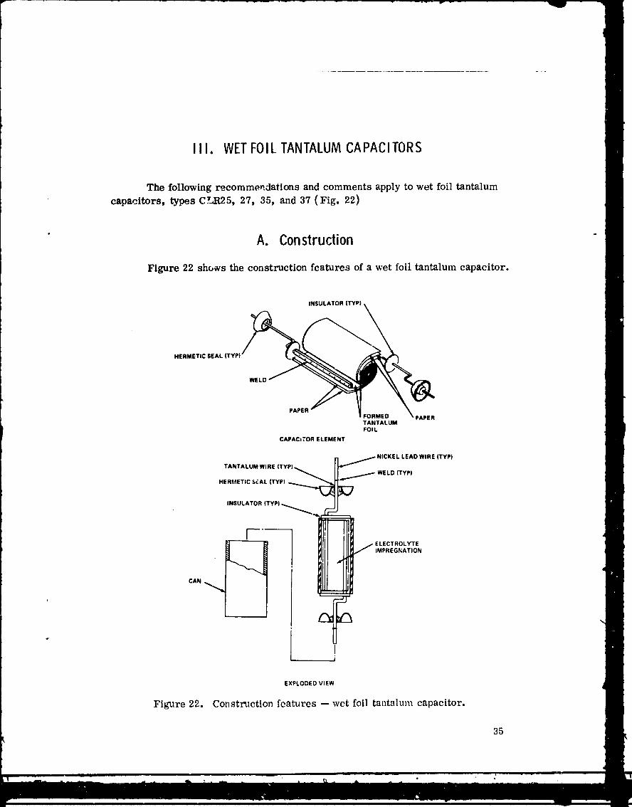
Iil. WETFOILTANTALUMCAPACITORS
The following recommendations and comments apply to wet foil tantalum
capacitors, types CLR25, 27, 35, and 37 (Fig. 22)
• A. Construction "
Figure 22 shc,_vs the construction features of a wet foil tantalum capacitor.
INSULATOR (TYPI
TANTALUMFOIL
CAPACITOR ELEMENT
NICKEL LEAD WIRE (TYP)n
INSULAR |TVP)
I
EXPLODED VIEW
Figure 22. Construction features -- wet foil tantalum capacitor.
35
1978010368-044
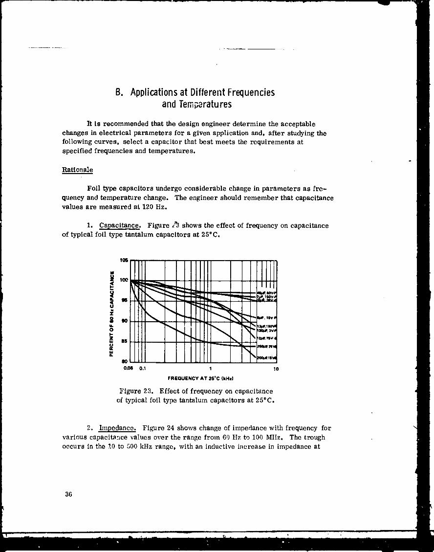
B. Applicationsat DifferentFrequenciesandTemperatures
It is recommended that the design engineer determine the acceptablechanges in electrical parameters for a given application and, after studying thefollowing curves, select a capacitor that best meets the requirements atspecified frequencies and temperatures.
Rationale
Foil type capacitors undergo considerable change in parameters as fre-
quency and temperature change. The engineer should remember that capacitancevalues are measured at 120 Hz.
1. Capacitance. Figure Z3 shows the effect of frequency on capacitanceof typical foil type tantalum capacitors at 25°C.
,, i80 I
O,,OQ 0.1 I 10
FREQUENCY AT 25=C (kHz)
Figure 23. Effect of frequency on capacitance
cf typical foll type tantalum capacitors at 25°C.
2. hnpedance. Figure 24 shows change of impedance with frequency for
various capacitance values over the range from 60 Hz to 100 Mttz. The trough
occurs in the ?.0 to 500 kHz range, with an inductive increase in impedance at
36
1978010368-045

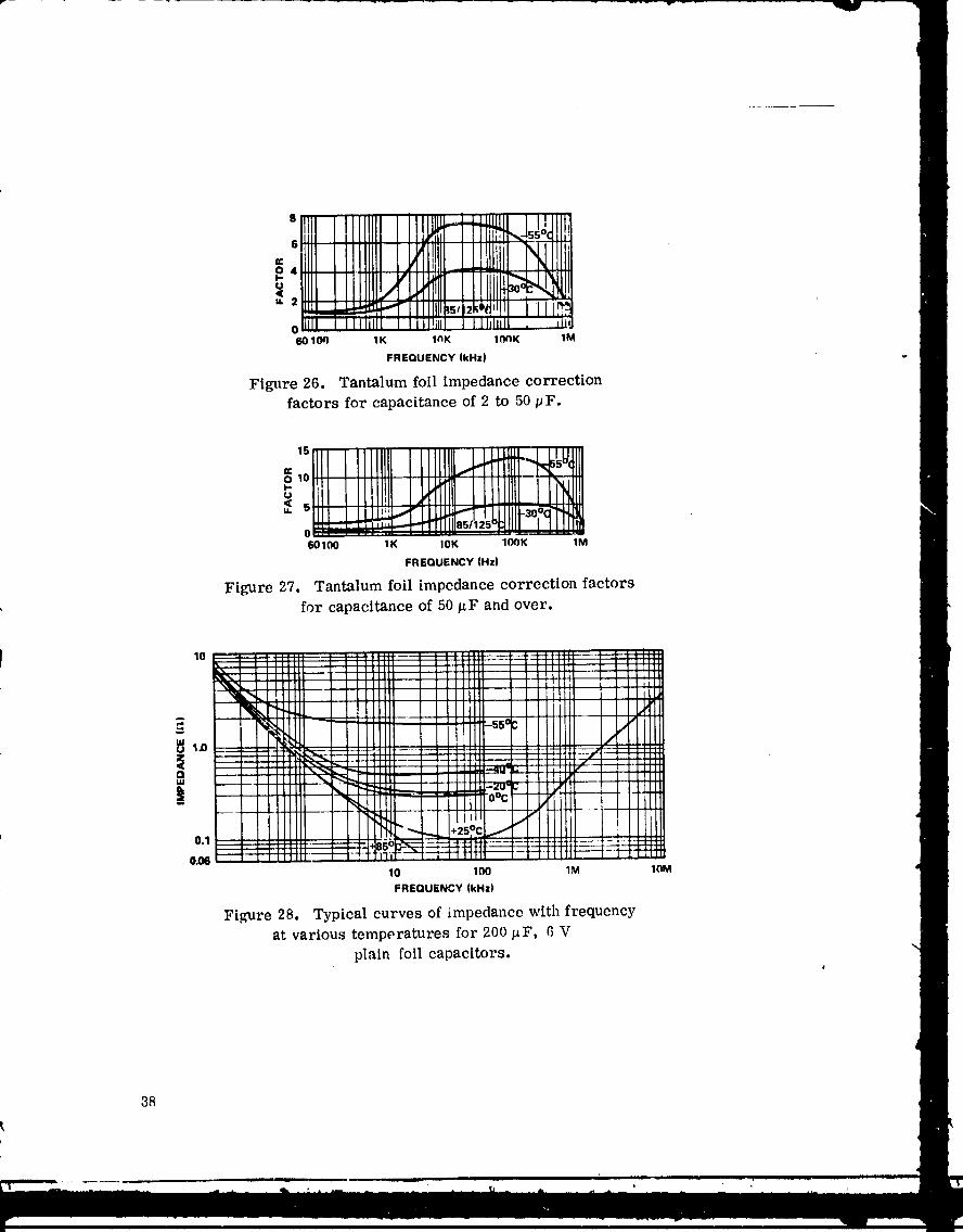
the higher frequencies. Figures 25 throt:gh 28 illustrate siz_ and temperaturecorrection factors to be applied to the impedance value obtained from Figure 24.
Since ESR increases significantly at low temperatures, these correction factorsmust be taken into consideration in design. Note that impedance at -55°C at
a given frequency may be several times the 25°C value. In general, one can saythat foil types change more in electrical parameters c.s frequency and temperature
change than do slug types. This is due primarily to the less conductive electro-lytes used and to the inductive effects of the foil winding. For example, capaci-tance change with temperature is positive and ranges from -20 to -40 percentat -55°C to an increase of 10 to 50 percent at 125°C.
8 ................. i'd-- ...... I
6 _--I--+,_+I
,u_ 2 .......
0_4--._::_-_4m, =_:_ _+,.. _.,,-.; .....60100 1K 1OK 100g 1M
FREQUENCY (kHz)
Figure 25. Tantalum foil impedance correction
factors for capacitance up to 2 # F.
37
• m
1978010368-046
1.... odill!e 111 ...... , _ 1
1..... ' L 'lllj+¢ m i
w i_l i1111'5/_2 ..... L,,- .,+ e_l_FIIIII +s42i_{llll 1i_
o [li [ Iit]l 11 Ill! , NIIII dJ!60 104_ 1K lnK 1linK 1M
FREQUENCY (kHz)
Figure 26. Tantalum foil impedance correctionfactors for capacitance of 2 to 50 pF.
O 10 . : :::::: : :. I-.- ....
° ,,=, __ ;; ,o,JIIr'°0-:!" :: ..i I .- . ---.60100 tK 10K IOOK 1M
FREQUENCY (Hz)
Figure 27. Tantalum foil impedance correction factorsfor capacitance of 50/_F and over.
i ....... :_:-_j, _, , ;;;;:10 ! -,!!! : : :+++H---_-- H;!-_ ----'4"--:-_ +e_--- V ' ....x ..... _L__I .... ii i , l ' ' ' [L:] [ .......... 111t. , _l " : : _llJll "
. I I _ ....... I: i . i Illl_j _ ::__1 ....... l, ! 1111il ] iiiji
-_ !!!!i! ! !! : -s5% ' ....- II, /
': ,._ , +H4ii+--i_ i-_ "_ _"J':'"' _' ..iii lJ) iii• "_-....... , , -=,,,i_.. ], lily" _i_i i ii+ -_%C u+++++ + I I
o., .:: L_ i;1_if-_i +.++i :.i.+l.e_?jr+-_'_-:'+-: ..____- " -- --0.06 ...............
10 100 1M 1AM
FREQUENCY (kN=)
Figure 28. Typical curves of impedance with frequencyat various temperatures for 200/_F, 6 V
plain foil capacitors,a
38
iL
1978010368-047

3. Equivalent Series Resistance. As shown in Figure 29, ESR increasesrapidly at temperatures below 0°C. This naturally affects impedance, DF, and
capacitance.
S_
,_ EQUIVALENT
SERIES RESISTANCE
- \<
- ......................CAPACITANCE -'"" _O.8
-55 -25 0 +25 +50 +75 +100 +125
TEMPERATURE (°C)
Figure 29. Typical curves of impedance, capacitance,and ESR with temperature for 26 pF, 100 V
polarized etched foil capacitors.
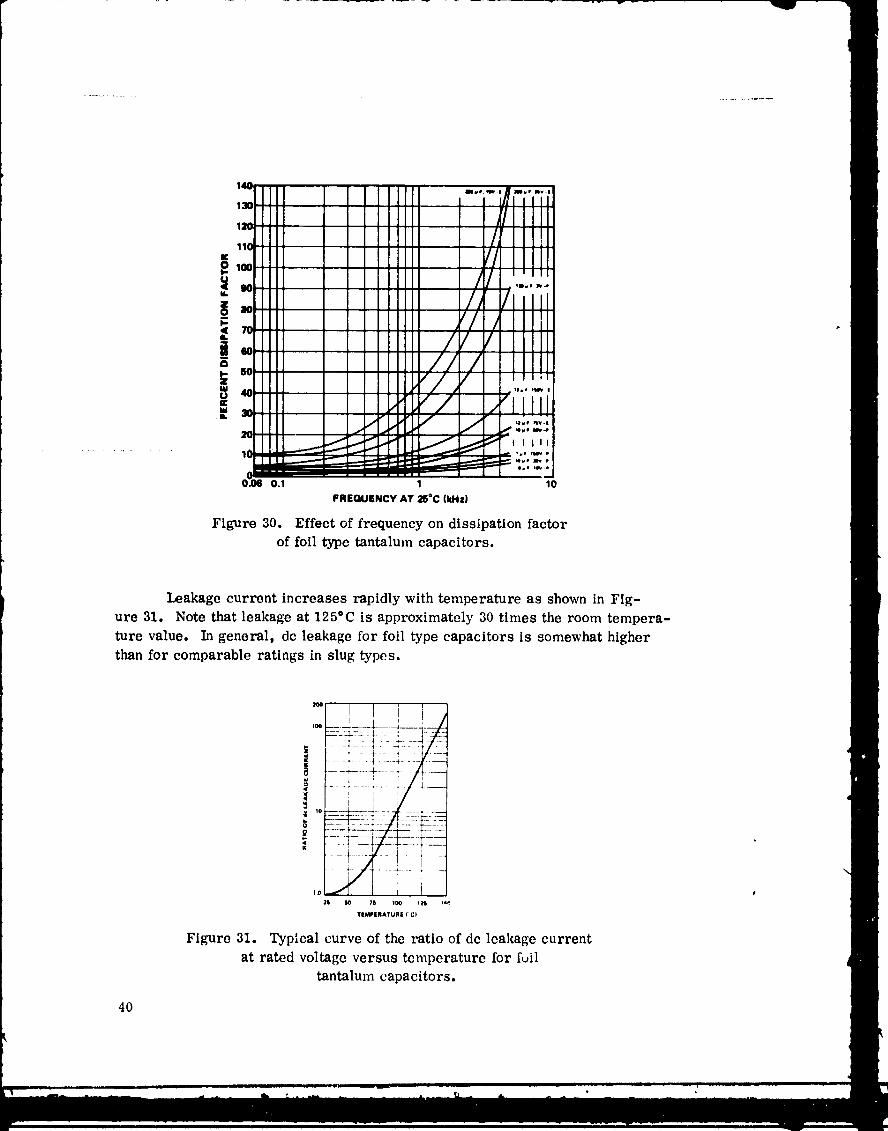
4. Dissipation Factor. DF increases rapidly with frequency, especiallyfor the higher capacitance values, mainly because of the time decrease in
capacitive reactance relative to the more constant value of ESR. Figure 30
depicts these DF changes.
5. _ Leakage current of foil tantalums is in the microampere
category and ranges from less than 1 to 100 _A or more, depending on electrical
rating, type of construction, and temperature.
Leakage current, as in all tantalum types, is the result of minute faultsin the dielectric film. These faults tend to be self-lmaliag under applied voltage;
consequently, leakage current will normally decrease exponentially with life.
" Leakage current is roughly proportional to applied voltage up to the
maximum dc voltagc rating.
39
1978010368-048
,® //
= /ilQ
WUKm • J
• ff
.J J .
0.1 1 10
FREGUENCY AT 25°C (kHz)
Figure 30. Effect of frequency on dissipation factorof foil type tantalum capacitors.
Leakage current increases rapidly with temperature as shown in Fig-
ure 31. Note that leakage at 125°C is approximately 30 times the room tempera-
ture value. In general, dc leakage for foil type capacitors is somewhat higher
than for comparable ratings in slug types.
; -
........... 4--- -4-
<
' ] i , ,
- f----t
i ,
TIMPIRATURI ('C)
Figure 31. Typical curve of the ratio of dc leakage current
at rated voltage versus temperature for full
tantalum capacitors.
4O
1978010368-049
C. Permissibleac Ripple
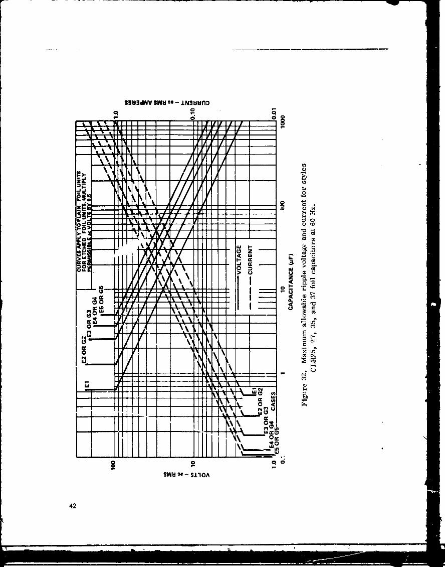
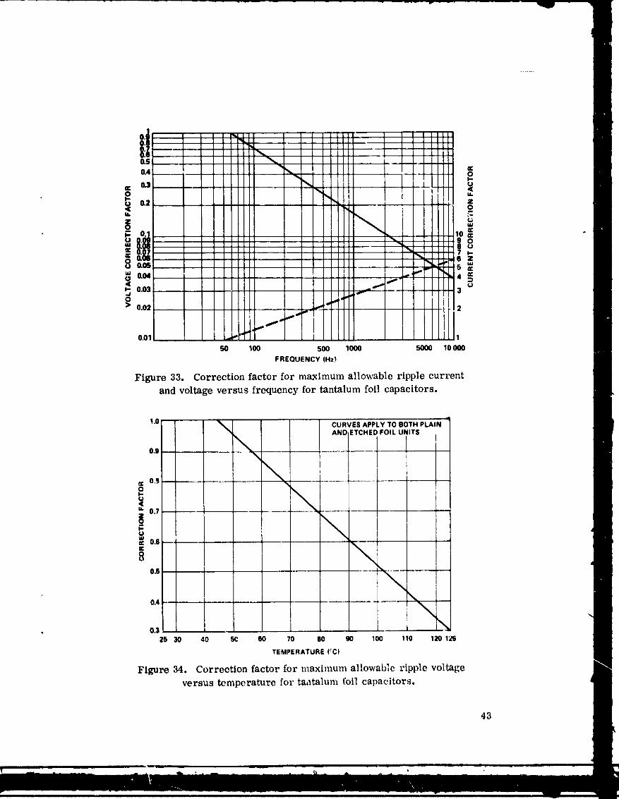
It is recommended that the curves in Figures 32, 33, and 34 be used in
selecting a fed capacitor for use in ac ripple applications.
Since foil type capacitors can be made nonpolar quite easily (thus per-
mitting as much reverse bias as forward bias), the question often arises as to
whether they may be used in ac applications without any dc bias. While test data °
are rather scarce for this application, it may be said in general that raw ac may
be applied to these nonpolar capacitors if proper derating of voltage is followed.It is suggested that in such unusual applications the design engineer contact the
vendor for advice. The engineer should provide information on waveform,
temperature ranges, peak and RMS voltages and current, duty cycles, corona,etc.
D. TemperatureRiseLimitationDueto ac Ripple
Follow the same recommendations as for solid tantalums in Para-
graph II. E.
E. DielectricProtection
It is recommended that voltage surges not exceed the rated voltage at
the respective temperature, and that for critical space applications the steady-
state voltage be derated to 60 percent of rated voltage at the respective tempera-
ture (as stated in Paragraph I.J).
Rationale
While wet type tantalums tolerate higher voltages and voltage spikesbetter tlLan do the solids, they too can experience dielectric puncture. Figures
_5 and 36 show that the failure rate of these capacitors is a function of applied
• voltage and temperature. These are typical curves. They show that the failurerate increases sharply when the applied voltage is above 70 percent of rated
voltage. While the Increasing failure rate with temperature shown in Figure 36
• may be attributed to loss of electrolyte in hOp ermetically sealed capacitors,
causing degradation of electrical parameters, it is a well known fact that
elevated temperatures degrade the dielectric (Ta20 s) and may cause high dc
leakage or eventual dielectric rupture and shorts.
41
1978010368-050
42
1978010368-051
0.01 1
5O 100 50O 1000 5000 10O00FREQUENCY(Hz!
Figure 33. Correction factor for maximum allowable ripple currentand voltage versus frequency for tantalum foil capacitors.
1.0 _ CURVESAPPLYTOBOTHPLAIN-% ANDETCHEOFOIL UNITS
o.o _ I_ I\
¢ 0.9
° \_ 0.7 _---
, \uul¢ 0.6mE \8
0.§ ......
\
0.4 _
, o._ I \2. 30 40 _ 60 70 .o go loo .o 12o_
TEMPERATURE(°C)
Figure 34. Correction factor for maximum allowable ripple voltageversus temperat_lre for ta,_talum i'oil capacitors.
43
1978010368-052

I qF--_
10
/j/
- /¢
i
I-. j .< J
W 1
_m I J.j v
J" o.1 i_,.,"
65 70 80 90 100 110 120 130
PERCENT OF RATED VOLTAGE AT 85°C
Figure 35. Typical effects of applied dc voltage
on failure rate of foil capacitors,
1O111111
W¢
1000 /
/m f
0t,-Z_ 11111u
w j
f
20 _"J_'J25 50 75 100 125
TEMPERATURE (°C)
Figure 36. Typical effects of temperature on failurerate of [oil capacitors.
44
1978010368-053
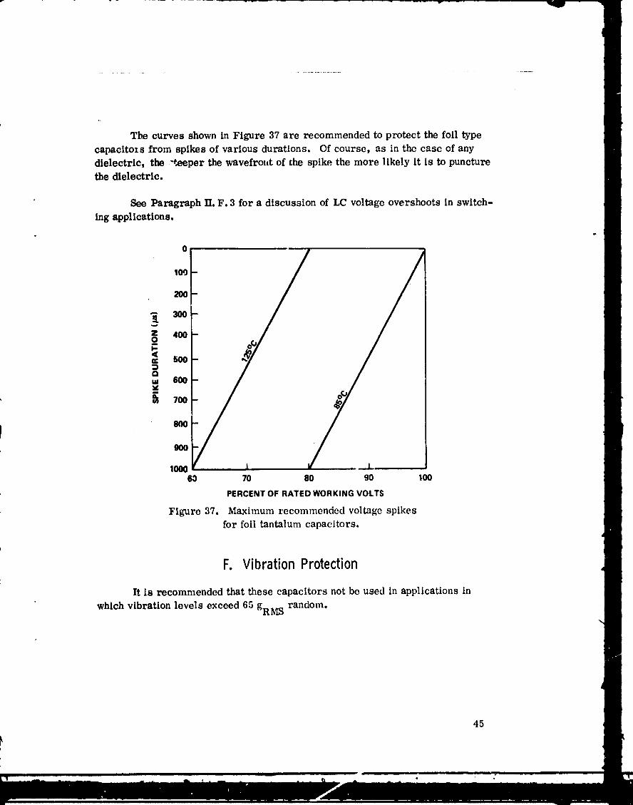
The curves shown in Figure 37 are recommended to protect the foil type
capacitozs from spikes of various durations. Of course, as in the case of anydielectric, the -t_eper the wavefro_lt of the spike the more likely it is to puncturethe dielectric.
See Paragraph II. F. 3 for a discussion of LC voltage overshoots in switch-
ing applications.
_ 300-
lO00 I I60 70 80 90 100
PERCENTOFRATEDWORKINGVOLTS
Figure 37. Maximum recommended voltage spikesfor foil tantalum capacitors.
Fo Vibration Protection
It Is recommended that these capacitors not be used in applications in
which vibration levels exceed 65 gRMS random.
45
1978010368-054
Rationalei •
The windings in the capacitor case should not fit too tightly lest the foil
puncture the paper separators and cause a short. Therefore, unlike the slugtypes in which the solid is so!der encased and the wet slug Is firmly held bye_on "spiders," the foil capacitor cannot tolerate high vibration because of the
loose fit of the winding in the case. Capacitors can be made to tolerate highervibration levels by using grommets in each end.
46
q
1978010368-055
J
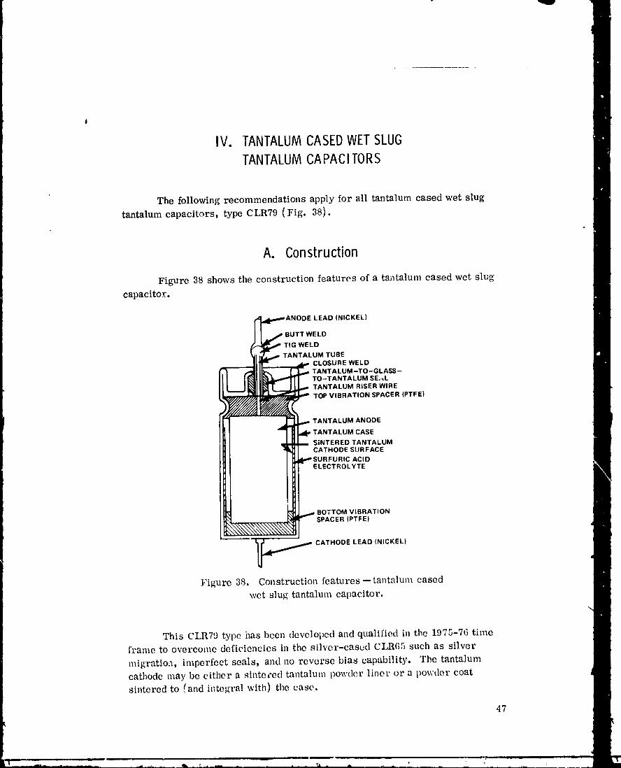
IV. TANTALUMCASEDWETSLUGTANTALUMCAPAClTORS
The following recommendations apply for all tantalum cased wet slug
tantalum capacitors, type CLR79 (Fig. 38).
A. Construction
Figure 38 shows the construction features of a tantalum cased wet slugcapacitor.
LEAD (NICKEL)
BUTT WELD
TIG WELD
TANTALUM TUBECLOSURE WELDTANTALUM-TO-GLASS-TO-TANTALUM SE,;_LTANTALUM RISER WIRETOP VIBRATION SPACER (PTFE)
TANTALUM ANODE
TANTALUM CASE
SINTERED TANTALUMCATHODE SURFACE
C ACIDELECTROLYTE
BOTTOMVIBRATIONSPACER(PTFEI
,,_.,_ CATHODELEAD(NICKEL)
},'igure 38. Construction features--tantalum cased
wet slug tantalum capacitor.
This CLR79 type has been developed and qualilicd in the 1975-76 timeframe to overcome deficiencies in the silver-eased CLR(;5 such as silver
migration, imperfect seals, and no reverse bias capability. The tantalumcathode may be either a sinteL-ed tantalum powder liner or a powder coat
sintcred to (and integral with) the case,
47
1978010368-056

B. Applicationsat DifferentFrequenciesandTemperatures
It is recommended that the design engineer determine the acceptable
changes in electrical parameters for a given application under different fre-quency and temperature conditions, and select the wet slug capacitor that bestmeets the requirements, based on information giver, by the following curves.
Rationale
Wet slug capacitors undergo some change in e]ectrical parameters (as do
the older silver-cased units) as frequency and temperature change. Generally,
these changes are not as severe as for etched foil capacitors, bu _,are slightly
greater than for the solids. Again, the engineer should remember that ratingsare measured at 120 Hz.
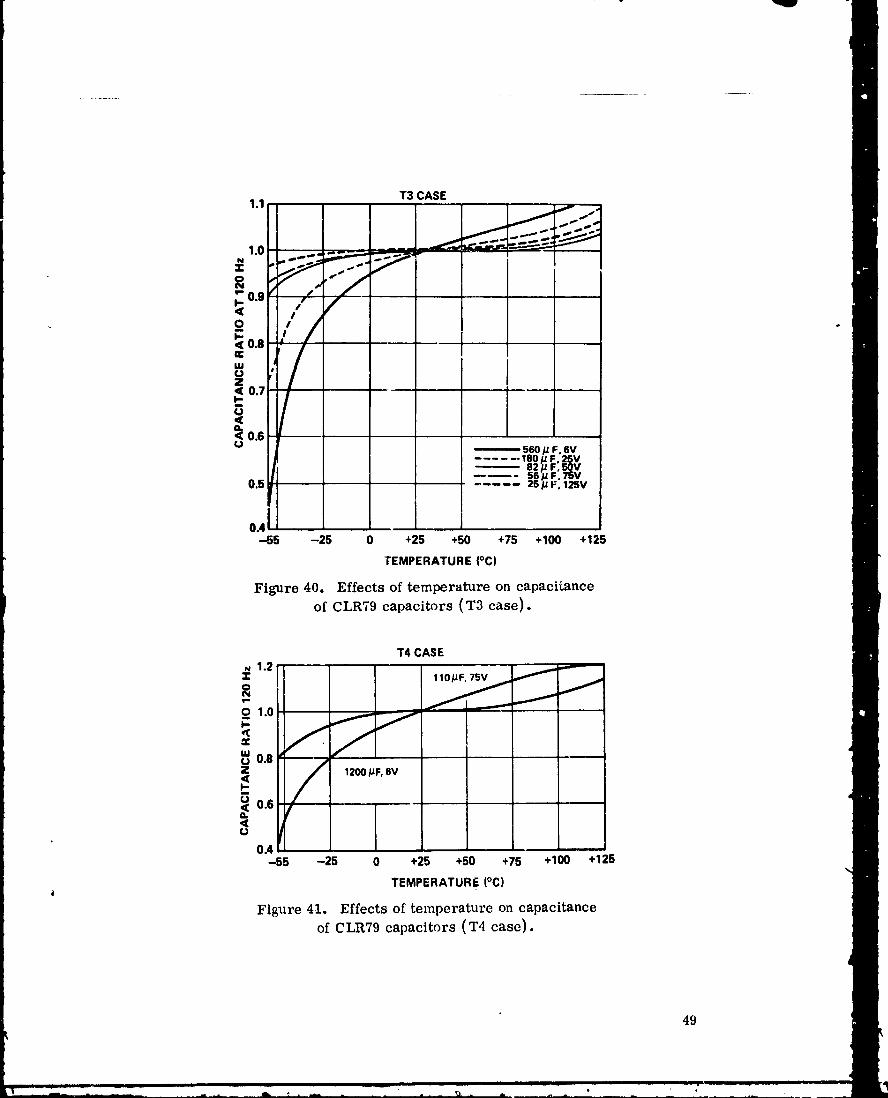
1. Capacitance. Figures 39, 40, and 41 show that capacitance valuesdecrease at low temperatures, and that the changes are greatest with high capaci-tance units and least with low capacitance units. Thus, the largest case (T4)
units exhibit the greatest changes.
T2 CASE1.1,
., .__ _'-__-_--
.-7o o.9
-7I,-<
_ 0.8Z __ 270 p F. 6V
180 _ F, 10V100/J F 25V
0.7 ,,,F:5ov,. t ........ 22,,.,oo_
14 # F, 125Vr
o.6 I ]-55 -25 0 +25 +50 +75 ._100 .125
TEMPERATURE(_C)
Figure 39. Effects of temperature on capacitance
of CLR79 capacitors (T2 case).
48
1978010368-057
T3 CASE1.1
1.0N3;
_0.9I-<
I-.< 0.8n-LUUZ< 0.7I-U<eL< 0.6(J
560# F,SV...... 180#F 2§V
82# F'50V56 # F' 75V
0.5 2S # I=_125V
o.,-55 -25 0 +25 +50 +75 +100 +125
TEMPERATURE (°C)
Figure 40. Effects of temperature on capaciLsneeof CLR79 capacitors (T3 case).
T4 :ASE,_ 1.2
0 1.0 / I ---.-/
_ 0.8
/ 12oo#F.svI-
_0.6<u
0.4-55 -25 0 +25 +50 +75 +100 +125
TEMPERATURE (°C)J
Figure 41. Effects of temperature on capacitanceof CLR79 capacitors (T4 case).
49
1978010368-058

2. Impedance. Figures 42 and 43 show that impedance changes with fre-quency, and temperature variations follow the same pattern as do those for other
capacitor types; however, the wet slug types can tolerate higher frequencies
with smaller changes in impedance than can the foils and about the same as forthe solids.
; ;i::::: tl;;;;; ; i i]]::::::;; .; .;
_! ; I ..... ' '"'" ' ' ' ['"' ' ..........;" [ i ..... 1 iilili I I 111111 I- . . ::::: : : : ::::: : :
,.L I .... I III1:11 i Illllll l
10 *
I 1111111"1 '_im,.LI [llll I ; l'tllr'_ltllli I I
......... I_,.IJllll I I I_ '4o 1IIIIII I
" I I IIIIIJ'_,L'_I . I IIIIII I
0.1 .... i ........0.1K 0,6K 1K 5K 10K 60K 100K S00K 1M 5M 10M
FREQUENCY (HI)
Figure 43. Typical curves of impedance with frequency at varioustemperatalres [or wet slug 25 pF, 125 V capacitors.
5O
1978010368-059
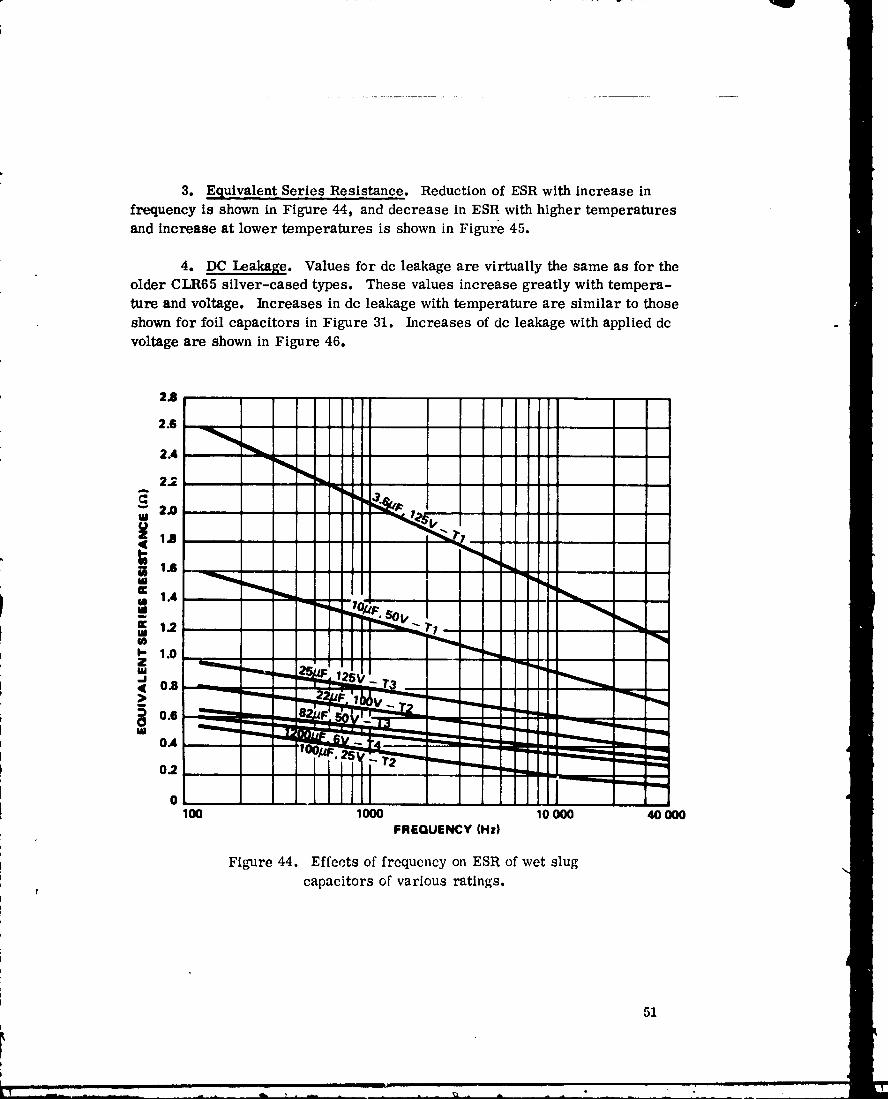
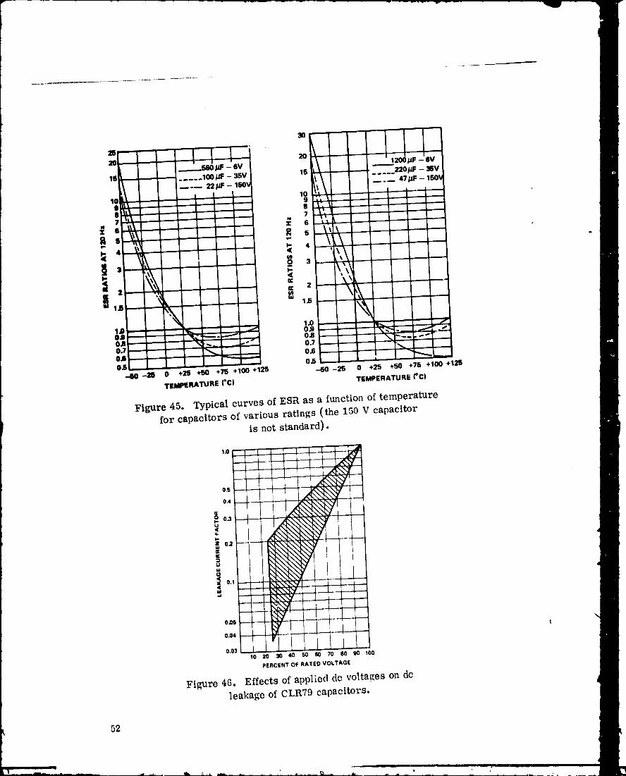
3. Equivalent Series Resistance. Reduction of ESR with increase in
frequency is shown in Figure 44, and decrease in ESR with higher temperatures
and increase at lower temperatures is shown in Figure 45.
4. DC Leakage. Values for dc leakage are virtually the same as for the
older CLR65 silver-cased types. These values increase greatly with tempera-
ture and voltage. Increases in dc leakage with temperature are similar to those
shown for foil capacitors in Figure 31. Increases of dc leakage with applied dc
voltage are shown in Figure 46.
2.8
2.6
2.4
2.2
2.o
I _ 1.6WOCW 1.4usH' 1,.2UllWI,- 1.0W.I
O_m.
0.60wOA
02
0100 1000 10000 40000
FREQUENCY (Hz)
Figure 44. Effects of frequency on ESR of wet slug
capacitors or various ratings°f
51
1978010368-060
3O
1I l
16 ..... IOOpF - 35V 15 L _"_.. 220pF - 35V
i ! ! 10 .. ,1 _tl 9
_'l_ - - - 7
¢e
2 ec 2 "
w 1.15 k m 1.5
'\In .,, 1.o
0,8 _-_'"-- _ 0,8 _'- "_ _-_'" ""- - 0.7 _ "'- "* "0.7- _ "" - _""
OA _ _ .--,- 0.6 I """0.5 0,5 • "_- _--
-..60-28 0 +25 +50 +75 +100 +125 --50-25 0 +25 +50 +76 +100 +12S
TEMPERATURE(°C) TEMPERATUREI°C)
Figure 45. Typical curves of ESR as a function of temperature
for capacitors of various ratings (the 150 V capacitor
is not standard).
os _ _\'_' t
0 0.3 : \\" . .
0.04 _- I
0,03 , , I
10 20 30 40 50 E0 70 80 90 100
PERCENT OF RATED VOLTAGE
Figure 46. Effects of appliect do voltages on dc
leakage of CLR79 capacitors.
52
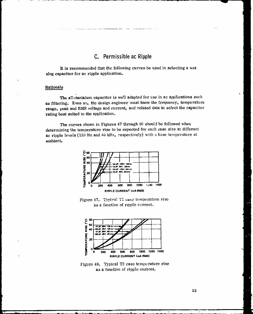
C. PermissibleacRipple
It is recommended that the following curves be used in selecting a wet
slug capacitor for ac ripple application.
Rationale
The all-_ntalum capacitor is well adapted for use in ac applications such
as filtering. Even so, the design engineer must know the frequency, temperature
range, peak and RMS voltage and current, and related data to select the capacitor
rating best suited to the application.
The curves shown in Figures 47 through 50 shou;d be followed whexz
determining the temperature rise to be expected for each case size at different
ac ripple levels (120 Hz and 40 kHz, respectively) with a base temperature atambient.
+ I 1""" YI.(40 . ,,J_. lav. Izo..
mw _ ___ --IO.UF sov. tIQN.
3.8_, i_v._dm
20 --,-io,_. my. 4okN* --
W_. 0 200 400 600 800 10(0) 1200 1400
RmP?LECURRENT(mARMS)
Figure 47. Typical 2'I case temperature riseas a function of rzpple current.
_60
I_+o .,.,,,+,,,.a--.jr jj-- .1_ 141_,1'llV,1N m --2kf_
W _/_. Iv, 40hNm._L'--m
EUl
200 400 600 800 1000 1200 14000
q l- RIPPLE CURRENT (mA RMS)
Figure 48. Typical T2 case temperature riseas a function of ripple current.
53
1978010368-062
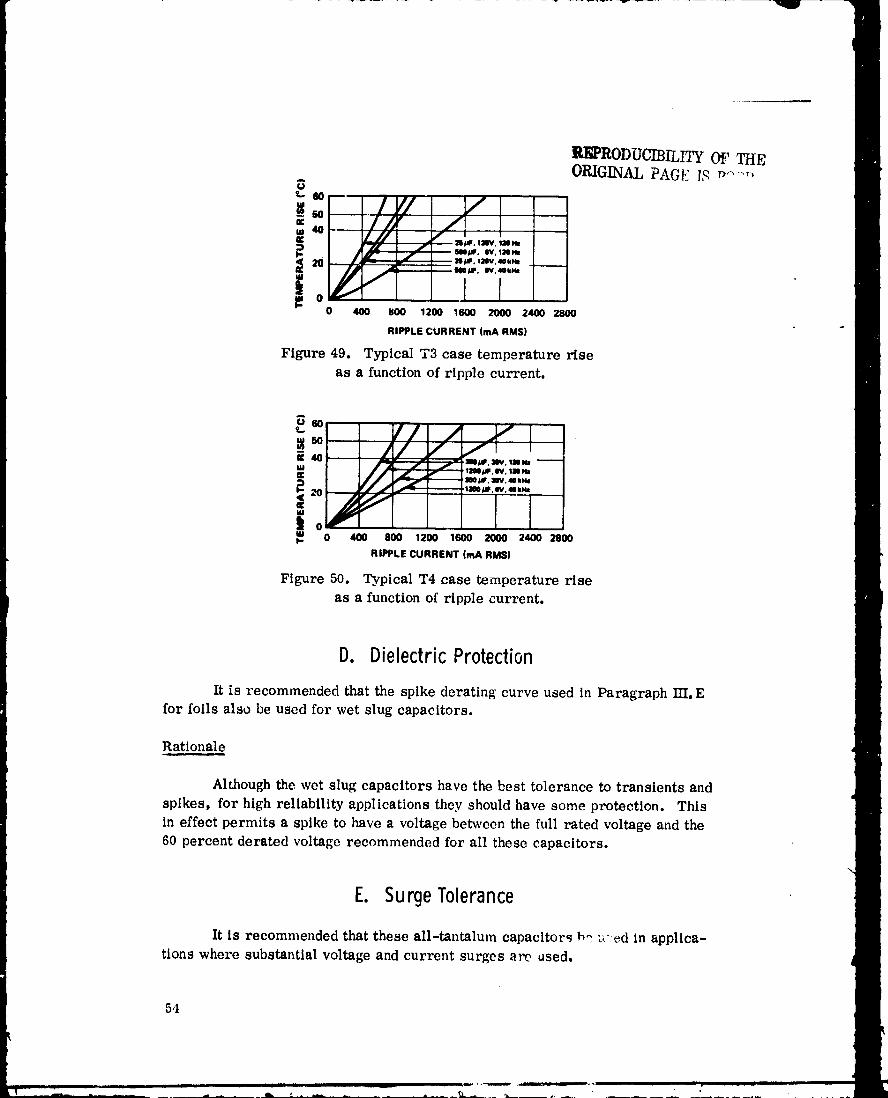
R_RODUCIBILITy OF THEORIGINAL PAG_ I,_ _.....
=_. !I/ /
i //" a/_F, 12EV, 40kH4
!oI,-
0 400 BOO 1200 1600 2000 2400 2800
RIPPLE CURRENT (mA RMS)
Figure 49. Typical T3 case temperature riseas a function of ripple current.
-,o / fl i
[i|oWt- 0 400 800 1200 1600 2000 2400 2800
RIPPLE CURRENT (mA RMS)
Figure 50. Typical T4 case temperature rise
as a function of ripple current.
D. DielectricProtection
It is recommended that the spike derating curve used in Paragraph IT[, Efor foils also be used for wet slug capacitors.
Rationale
Although the wet slug capacitors have the best tolerance to transients and
spikes, for high reliability applications they should have some protection. Thisin effect permits a spike to have a voltage between the full rated voltage and the
60 percent derated voltage recommended for all these capacitors.
E. SurgeTolerance
It is recommended that these all-tantalum capacitors P,_u: ed in applica-tions where substantial voltage and current surges are used.
54
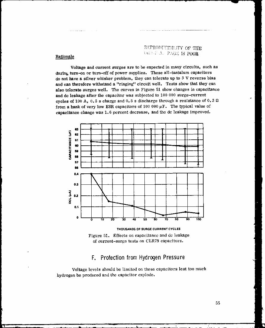
P_-:P_OT_!'C_[r,!TY O_ TrrElq_' i.' _ P .... '' ,... ,_u,', IS POOR
Rationale
Voltage and current surges are to be expected in many circuits, such asduring turn-on or turn-off of power supplies. These all-tantalum capacitorsdo not have a silver whisker problem, they can tolerate up to 3 V reverse biasand can therefore withstand a "ringing" circuit well. Tests show that they can
also tolerate surges weU. The curves in Figure 51 show changes in capacitanceand dc leakage after the capacitor was subjected to 100 000 surge-current
cycles of 100 A, 0.5 s charge and 0.5 s discharge through a resistance of 0.3 £
from a bank of very low ESR capacitors of 100 000/zF. The typical value of
capacitance change was 1.6 percent decrease, and the dc leakage improved.
62
61 _..........__...._...
H
57
OA
3 0_
0.1 _
O0 10 20 30 _ 50 60 70 80 _ 1_
THOUSANDSOFSURGECURRENTCYCLES
Figure 51. Effects on capacitance and dc leakage
of current-surge tests on CLR79 capacitors.
F. ProtectionfromHydrogenPressurew
Voltage lewls should be limited oa these capacitors lest too much
hydrogen be produced and the capacitor explode.
55
1978010368-064
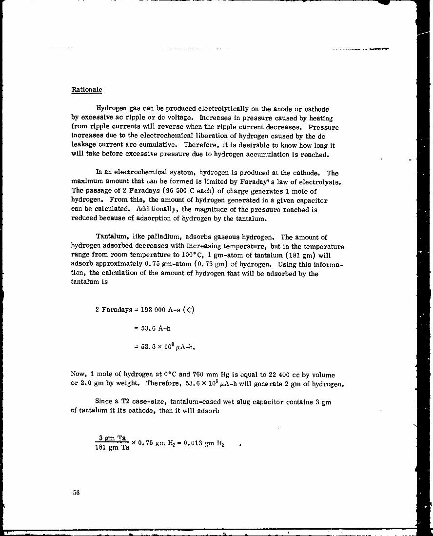
Rationale
Hydrogen gas can be produced electrolytically on the anode or cathodeby excessive ac ripple or dc voltage. Increases in pressure caused by heatingfrom ripple currents will reverse when the ripple current decreases. Pressure
increases due to the electrochemical liberation of hydrogen caused by the dcleakage current are cumulative. Therefore, it is desirable to know how long itwill take before excessive pressure due to hydrogen accumulation is reached.
In an electrochemical system, hydrogen is produced at the cathode. The
maximum amount that can be formed is limited by Faraday' s law of electrolysis.The passage of 2 Faradays (96 500 C each) of charge generates 1 mole of
hydrogen. From this, the amount of hydrogen generated in a given capacitorcan be calculated. Additionally, the magnitude of the pressure reached is
reduced because of adsorption of hydrogen by the tantalum.
Tantalum, like palladium, adsorbs gaseous hydrogen. The amount ofhydrogen adsorbed decreases with increasing temperature, but in the temperaturerange from room temperature to 100°C, 1 gin-atom of tantalum (181 gm) willadsorb approximately 0.75 gm-atom (0.75 gm) of hydrogen. Using this informa-tion, the calculation of the amount of hydrogen that will be adsorbed by thetantalumis
2 Faradays = 193 O00 A-s (C)
= 53.6 A-h
= 53. G × I0 e/_A-h.
Now, 1 mole of hydrogen at 0°C and 760 mm Hg is equal to 22 400 cc by volume
or 2.0 gm by weight. Therefore, 53.6 x 10⁶ pA-h will generate 2 gm of hydrogen.
Since a T2 case-size, tantalum-cased wet slug capacitor contains 3 gmof tantalum it its cathode, then it will adsorb
3 gm Ta×0.75gin H2=0.013 gmH_ .
181 gm Ta
56
1978010368-065
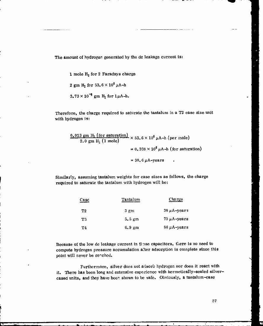
The amount ofhydrogev,generatedby the dc leakagecurrentis:
1 mole H2 for 2 Faradays charge
2 gm H2 for 53.6 x 10⁶ #A-h
3.73 × 10 -8 gm H2 for l_A-h.
Therefore, the charge required to saturate the tantalum in a T2 case size unitwith hydrogen is:
0.013 gm H2 (for saturation)_ x 53.6 × 10⁶/_A-h (per mole)2.0 grn It.. (1 mole)
ffi 0.338 x 10⁶ _A-h (for saturation)
= 38.6/_A-years .
Similarly, assuming tantalum weights for case sizes as follows, the charge
required to saturate, the tantalum with hydrogen will be:
Cas___£ Tantalum
T2 3 gm 38 _A-year_
T3 5.5 gm 70 lzA-years
T4 6.9 gm 88 _A-years
Because of the low dc leakage current in tl:_se capacitors, there is no need to
compute hydrogen pressure accumulation after adsorption is complete since thispoint will never be re,.ched.
' Furthermore, silver does not adsorb hydrogen nor does it react withit. There has been long and extensive experience with hermetically-sealed silver-
cased units, and they have bee.-, shown to be safe. Obviously, a t#mtalum--case
57
1978010368-066
capacitor, which has the capability of adsorbing hydrogen even at room tempera-ture, is even less likely to have problems because of hydrogen generation.While tantalum embrittles with hydrogen, this is not a danger due to _e smallamounts of gas produced.
G. VoltageDeratingD
The voltage applied to these capacitors shall not exceed 60 percent of the
rated voltage at 85°C and 125°C, respectively. (The 125°C rated voltage is67 percent of 85=C rated voltageo )
Rationale
The maximum rated voltage at 85 and 125=C is 125 and 82 V, respectively,per MIL-C-39006/22. Data tend to show that operation of these devices above
125 V with the present design using sulfuric acid electrolyte may cause dielectricdeterioration.
H. SpikeProtection
Use the same curve as for foils, namely Figure 37.
58
1978010368-067

APPROVAL
GUIDELINE3FORTHESELECTIONAND APPLICATIONOFTANTALUMELECTROLYTICCAPACITORS
!NHIGHLYRELIABLEEQUIPMENT
By Dr. A. M. Holladay
The information in this report has been reviewed for security classifi-
cation. Review of any information concerning Department of Defense or nuclear
energy activities or programs has been made by the MSFC Security Classification
Officer. This report, in its entirety, has been determined to be unclassified.
A. M. HOLLADAY \_/Staff, Electronics Development Division
fiamUSONGAIm_TChief, Electronics Development Division
F. BROOKS MOORE
DirectoL', Electronics and Control Laboratory
59J0' U, S, GOVERNMENT PRINTING OFFICE 1978 -740193/224 REGION NO,4
_ ii ill .... , .......
1978010368-068