Embed Size (px)
Citation preview
600SS 600SS
Sheet 1 of 34
ere19
S T A T E O F T E N N E S S E E
(Rev. 5-18-15) January 1, 2015
(Rev.11-16-15)
(Rev. 6-27-16)
(Rev. 12-2-16)
(Rev. 5-15-17)
(Rev. 11-6-17)
(Rev. 5-14-18)
(Rev. 10-8-18)
(Rev. 5-13-19)
(Rev. 12-30-19)
Supplemental Specifications - Section 600
of the
Standard Specifications for Road and Bridge Construction
January 1, 2015
Subsection 602.17 (pg.459-477), 12-2-16; Entire Subsection: Replace all references to AASHTO M164
and AASHTO M253 with ASTM F3125, Grade A325 and A490
Subsection 602.17 (pg. 459) 12-2-16; modify the first paragraph of A.:
“All high strength bolts, or equivalent fasteners, tightened to a high tension shall be coated with
permitted coatings in accordance with ASTM F3125 for their respective grade. Use the bolts in
holes conforming to 602.06, 602.07, and 602.08. All Grade A325 and A490 bolts, except Type 3
bolts used in weathering steel, shall be coated. Permitted coatings for Grade A325 and Grade
A490 bolts are listed in ASTM F3125, Annex A1.”
Subsection 602.17 (pg. 465–469), 12-2-16; Update Tables:
Bolt Diameter
(inches)
Bolt Tension (pounds)
(GradeA325)
GradeA490 Bolts
½ 12,000 15,000
5/8 19,000 24,000
¾ 28,000 35,000
7/8 39,000 49,000
1 51,000 64,000
1-1/8 64,000 80,000
1-1/4 81,000 102,000
1-3/8 97,000 121,000
1-1/2 118,000 148,000
600SS 600SS
Sheet 2 of 34
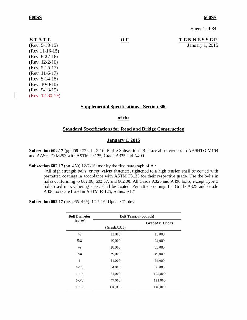
Table 602.17-1: Minimum Bolt Tension (1)
Bolt Diameter (inches) Grade A325
Snug Tension (kips)
Grade A490
Snug Tension (kips)
½ 1 1
5/8 2 2
¾ 3 4
7/8 4 5
1 5 6
1-1/8 6 8
1-1/4 8 10
1-3/8 10 12
1-1/2 12 15
Table 602.17-3: Minimum Installation Tension
Bolt Diameter (inches) Grade A325
Tension (kips)
Grade A490
Tension (kips)
1/2 12 15
5/8 19 24
3/4 28 35
7/8 39 49
1 51 64
1-1/8 64 80
1-1/4 81 102
1-3/8 97 121
1-1/2 118 148
Table 602.17-4: Rotation from Snug Condition
Bolt Length
(measured in Step 1)
Grade A325
Required
Rotation
Grade A490
Required
Rotation
Up to and including 4 diameters 2/3 2/3
Over 4 diameters, but not exceeding
8 diameters
1 5/6
Over 8 diameters to 12 diameters 1-1/6 1
(1) Equal to 70% of the specified minimum tensile strength of bolts.
600SS 600SS
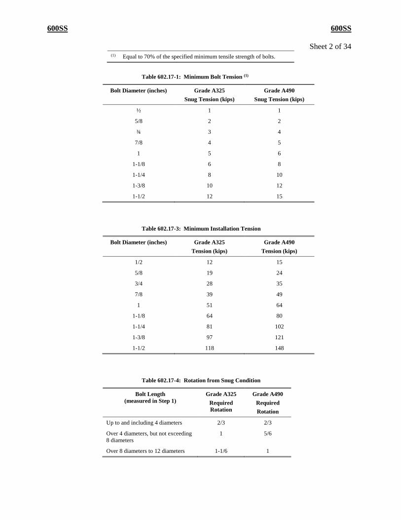
Sheet 3 of 34 Table 602.17-5: Turn Test Tension
Bolt Diameter (inches) Grade A325
Tension (kips)
Grade A490
Tension (kips)
1/2 14 17
5/8 22 28
3/4 32 40
7/8 45 56
1 59 74
1-1/8 74 92
1-1/4 94 117
1-3/8 112 139
1-1/2 136 170
Table 602.17-6
Bolt Length
(measured in Step 1)
Required
Rotation
(All Grades)
Up to and including 4 diameters 1/3
Over 4 diameters, but not
exceeding 8 diameters
½
Table 602.17-7
Bolt Diameter (inches) Grade A325
Torque (ft-lbs)
Grade A490
Torque (ft-lbs)
1/2 150 180
5/8 290 370
3/4 500 630
7/8 820 1020
1 1,230 1540
1-1/8 1,730 2160
1-1/4 2,450 3050
1-3/8 3,210 3980
1-1/2 4,250 5310
600SS 600SS
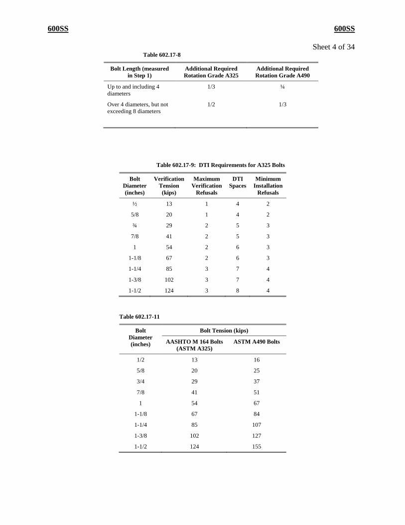
Sheet 4 of 34 Table 602.17-8
Bolt Length (measured
in Step 1)
Additional Required
Rotation Grade A325
Additional Required
Rotation Grade A490
Up to and including 4
diameters
1/3 ¼
Over 4 diameters, but not
exceeding 8 diameters
1/2 1/3
Table 602.17-9: DTI Requirements for A325 Bolts
Bolt
Diameter
(inches)
Verification
Tension
(kips)
Maximum
Verification
Refusals
DTI
Spaces
Minimum
Installation
Refusals
½ 13 1 4 2
5/8 20 1 4 2
¾ 29 2 5 3
7/8 41 2 5 3
1 54 2 6 3
1-1/8 67 2 6 3
1-1/4 85 3 7 4
1-3/8 102 3 7 4
1-1/2 124 3 8 4
Table 602.17-11
Bolt
Diameter
(inches)
Bolt Tension (kips)
AASHTO M 164 Bolts
(ASTM A325)
ASTM A490 Bolts
1/2 13 16
5/8 20 25
3/4 29 37
7/8 41 51
1 54 67
1-1/8 67 84
1-1/4 85 107
1-3/8 102 127
1-1/2 124 155
600SS 600SS
Sheet 5 of 34
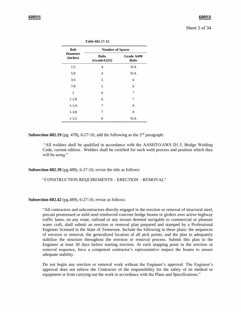
Table 602.17-12
Bolt
Diameter
(inches)
Number of Spaces
Bolts
(GradeA325)
Grade A490
Bolts
1/2 4 N/A
5/8 4 N/A
3/4 5 6
7/8 5 6
1 6 7
1-1/8 6 7
1-1/4 7 8
1-3/8 7 8
1-1/2 8 N/A
Subsection 602.19 (pg. 478), 6-27-16; add the following as the 2nd paragraph:
“All welders shall be qualified in accordance with the AASHTO/AWS D1.5, Bridge Welding
Code, current edition. Welders shall be certified for each weld process and position which they
will be using.”
Subsection 602.39 (pg.488), 6-27-16; revise the title as follows:
“CONSTRUCTION REQUIREMENTS – ERECTION – REMOVAL”
Subsection 602.42 (pg.489), 6-27-16; revise as follows:
“All contractors and subcontractors directly engaged in the erection or removal of structural steel,
precast prestressed or mild steel reinforced concrete bridge beams or girders over active highway
traffic lanes, on any route, railroad or any stream deemed navigable to commercial or pleasure
water craft, shall submit an erection or removal plan prepared and stamped by a Professional
Engineer licensed in the State of Tennessee. Include the following in these plans: the sequences
of erection or removal, the generalized location of all pick points, and the plan to adequately
stabilize the structure throughout the erection or removal process. Submit this plan to the
Engineer at least 30 days before starting erection. At each stopping point in the erection or
removal sequence, have a competent contractor’s representative inspect the beams to ensure
adequate stability.
Do not begin any erection or removal work without the Engineer’s approval. The Engineer’s
approval does not relieve the Contractor of the responsibility for the safety of its method or
equipment or from carrying out the work in accordance with the Plans and Specifications.”
600SS 600SS
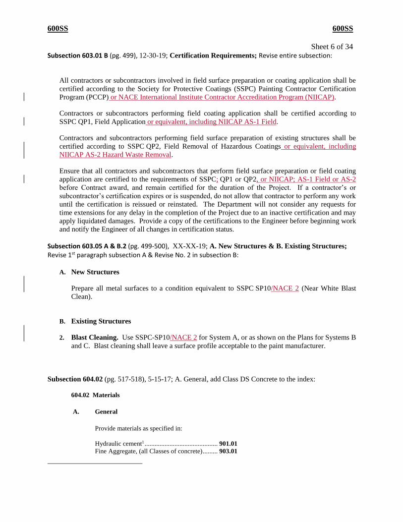
Sheet 6 of 34 Subsection 603.01 B (pg. 499), 12-30-19; Certification Requirements; Revise entire subsection:
All contractors or subcontractors involved in field surface preparation or coating application shall be
certified according to the Society for Protective Coatings (SSPC) Painting Contractor Certification
Program (PCCP) or NACE International Institute Contractor Accreditation Program (NIICAP).
Contractors or subcontractors performing field coating application shall be certified according to
SSPC QP1, Field Application or equivalent, including NIICAP AS-1 Field.
Contractors and subcontractors performing field surface preparation of existing structures shall be
certified according to SSPC QP2, Field Removal of Hazardous Coatings or equivalent, including
NIICAP AS-2 Hazard Waste Removal.
Ensure that all contractors and subcontractors that perform field surface preparation or field coating
application are certified to the requirements of SSPC; QP1 or QP2, or NIICAP; AS-1 Field or AS-2
before Contract award, and remain certified for the duration of the Project. If a contractor’s or
subcontractor’s certification expires or is suspended, do not allow that contractor to perform any work
until the certification is reissued or reinstated. The Department will not consider any requests for
time extensions for any delay in the completion of the Project due to an inactive certification and may
apply liquidated damages. Provide a copy of the certifications to the Engineer before beginning work
and notify the Engineer of all changes in certification status.
Subsection 603.05 A & B.2 (pg. 499-500), XX-XX-19; A. New Structures & B. Existing Structures;
Revise 1st paragraph subsection A & Revise No. 2 in subsection B:
A. New Structures
Prepare all metal surfaces to a condition equivalent to SSPC SP10/NACE 2 (Near White Blast
Clean).
B. Existing Structures
2. Blast Cleaning. Use SSPC-SP10/NACE 2 for System A, or as shown on the Plans for Systems B
and C. Blast cleaning shall leave a surface profile acceptable to the paint manufacturer.
Subsection 604.02 (pg. 517-518), 5-15-17; A. General, add Class DS Concrete to the index:
604.02 Materials
A. General
Provide materials as specified in:
Hydraulic cement1 ............................................ 901.01
Fine Aggregate, (all Classes of concrete) ......... 903.01
600SS 600SS
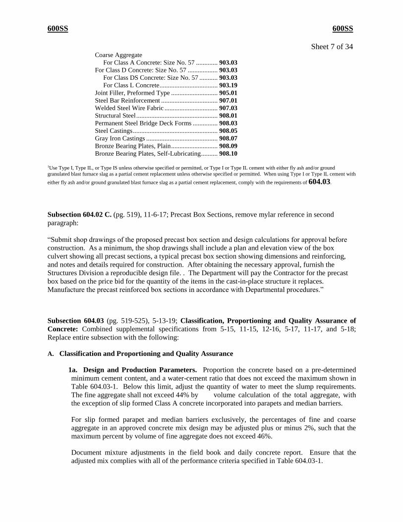
Sheet 7 of 34 Coarse Aggregate
For Class A Concrete: Size No. 57 ............. 903.03
For Class D Concrete: Size No. 57 .................. 903.03
For Class DS Concrete: Size No. 57 ........... 903.03
For Class L Concrete ................................... 903.19
Joint Filler, Preformed Type ............................ 905.01
Steel Bar Reinforcement .................................. 907.01
Welded Steel Wire Fabric ................................ 907.03
Structural Steel ................................................. 908.01
Permanent Steel Bridge Deck Forms ............... 908.03
Steel Castings ................................................... 908.05
Gray Iron Castings ........................................... 908.07
Bronze Bearing Plates, Plain ............................ 908.09
Bronze Bearing Plates, Self-Lubricating .......... 908.10
1Use Type I, Type IL, or Type IS unless otherwise specified or permitted, or Type I or Type IL cement with either fly ash and/or ground
granulated blast furnace slag as a partial cement replacement unless otherwise specified or permitted. When using Type I or Type IL cement with
either fly ash and/or ground granulated blast furnace slag as a partial cement replacement, comply with the requirements of 604.03.
Subsection 604.02 C. (pg. 519), 11-6-17; Precast Box Sections, remove mylar reference in second
paragraph:
“Submit shop drawings of the proposed precast box section and design calculations for approval before
construction. As a minimum, the shop drawings shall include a plan and elevation view of the box
culvert showing all precast sections, a typical precast box section showing dimensions and reinforcing,
and notes and details required for construction. After obtaining the necessary approval, furnish the
Structures Division a reproducible design file. . The Department will pay the Contractor for the precast
box based on the price bid for the quantity of the items in the cast-in-place structure it replaces.
Manufacture the precast reinforced box sections in accordance with Departmental procedures.”
Subsection 604.03 (pg. 519-525), 5-13-19; Classification, Proportioning and Quality Assurance of
Concrete: Combined supplemental specifications from 5-15, 11-15, 12-16, 5-17, 11-17, and 5-18;
Replace entire subsection with the following:
A. Classification and Proportioning and Quality Assurance
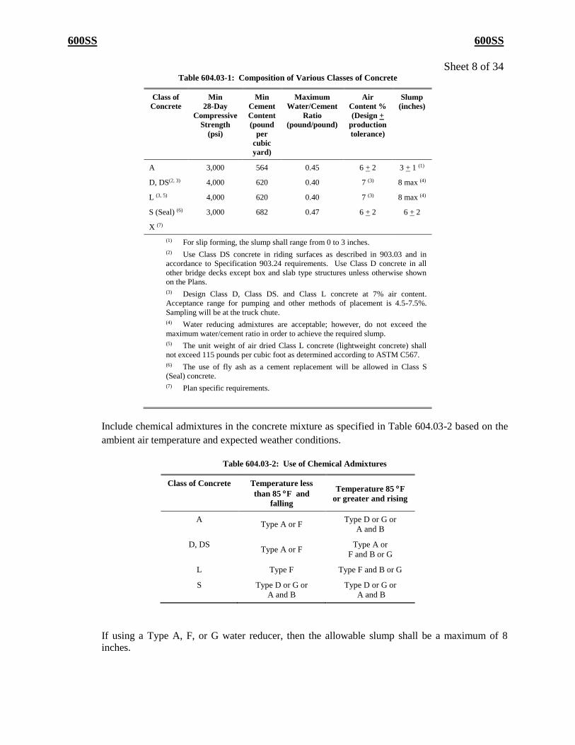
1a. Design and Production Parameters. Proportion the concrete based on a pre-determined
minimum cement content, and a water-cement ratio that does not exceed the maximum shown in
Table 604.03-1. Below this limit, adjust the quantity of water to meet the slump requirements.
The fine aggregate shall not exceed 44% by volume calculation of the total aggregate, with
the exception of slip formed Class A concrete incorporated into parapets and median barriers.
For slip formed parapet and median barriers exclusively, the percentages of fine and coarse
aggregate in an approved concrete mix design may be adjusted plus or minus 2%, such that the
maximum percent by volume of fine aggregate does not exceed 46%.
Document mixture adjustments in the field book and daily concrete report. Ensure that the
adjusted mix complies with all of the performance criteria specified in Table 604.03-1.
600SS 600SS
Sheet 8 of 34 Table 604.03-1: Composition of Various Classes of Concrete
Class of
Concrete
Min
28-Day
Compressive
Strength
(psi)
Min
Cement
Content
(pound
per
cubic
yard)
Maximum
Water/Cement
Ratio
(pound/pound)
Air
Content %
(Design +
production
tolerance)
Slump
(inches)
A 3,000 564 0.45 6 + 2 3 + 1 (1)
D, DS(2, 3) 4,000 620 0.40 7 (3) 8 max (4)
L (3, 5) 4,000 620 0.40 7 (3) 8 max (4)
S (Seal) (6) 3,000 682 0.47 6 + 2 6 + 2
X (7)
(1) For slip forming, the slump shall range from 0 to 3 inches.
(2) Use Class DS concrete in riding surfaces as described in 903.03 and in
accordance to Specification 903.24 requirements. Use Class D concrete in all
other bridge decks except box and slab type structures unless otherwise shown
on the Plans.
(3) Design Class D, Class DS. and Class L concrete at 7% air content.
Acceptance range for pumping and other methods of placement is 4.5-7.5%.
Sampling will be at the truck chute.
(4) Water reducing admixtures are acceptable; however, do not exceed the
maximum water/cement ratio in order to achieve the required slump.
(5) The unit weight of air dried Class L concrete (lightweight concrete) shall
not exceed 115 pounds per cubic foot as determined according to ASTM C567.
(6) The use of fly ash as a cement replacement will be allowed in Class S
(Seal) concrete.
(7) Plan specific requirements.
Include chemical admixtures in the concrete mixture as specified in Table 604.03-2 based on the
ambient air temperature and expected weather conditions.
Table 604.03-2: Use of Chemical Admixtures
Class of Concrete Temperature less
than 85 F and
falling
Temperature 85 F
or greater and rising
A Type A or F
Type D or G or
A and B
D, DS Type A or F
Type A or
F and B or G
L Type F Type F and B or G
S Type D or G or
A and B
Type D or G or
A and B
If using a Type A, F, or G water reducer, then the allowable slump shall be a maximum of 8
inches.
600SS 600SS
Sheet 9 of 34 Admixtures to be incorporated into the concrete shall all be from the same manufacturer, shall be
compatible, and shall be incorporated into the concrete in accordance with the manufacturer’s
recommendations.
The fine aggregate in all Class L concrete shall be natural sand meeting 903.01.
Do not use fine aggregate manufactured from limestone or other polishing aggregates in concrete
to be used as a riding surface in traffic lanes.
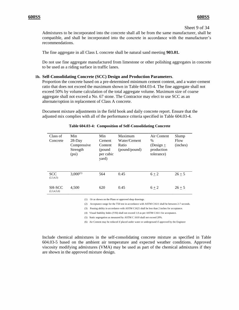
1b. Self-Consolidating Concrete (SCC) Design and Production Parameters.
Proportion the concrete based on a pre-determined minimum cement content, and a water-cement
ratio that does not exceed the maximum shown in Table 604.03-4. The fine aggregate shall not
exceed 50% by volume calculation of the total aggregate volume. Maximum size of coarse
aggregate shall not exceed a No. 67 stone. The Contractor may elect to use SCC as an
alternate/option in replacement of Class A concrete.
Document mixture adjustments in the field book and daily concrete report. Ensure that the
adjusted mix complies with all of the performance criteria specified in Table 604.03-4.
Table 604.03-4: Composition of Self-Consolidating Concrete
Class of
Concrete
Min
28-Day
Compressive
Strength
(psi)
Min
Cement
Content
(pound
per cubic
yard)
Maximum
Water/Cement
Ratio
(pound/pound)
Air Content
%
(Design +
production
tolerance)
Slump
Flow
(inches)
SCC (2,3,4,5)
3,000(1) 564 0.45 6 + 2 26 + 5
SH-SCC (2,3,4,5,6)
4,500 620 0.45 6 + 2 26 + 5
(1) Or as shown on the Plans or approved shop drawings.
(2) Acceptance range for the T50 test in accordance with ASTM C1611 shall be between 2-7 seconds.
(3) Passing ability in accordance with ASTM C1621 shall be less than 2 inches for acceptance.
(4) Visual Stability Index (VSI) shall not exceed 1.0 as per ASTM C1611 for acceptance.
(5) Static segregation as measured by ASTM C 1610 shall not exceed 20%.
(6) Air Content may be reduced if placed under water or underground if approved by the Engineer
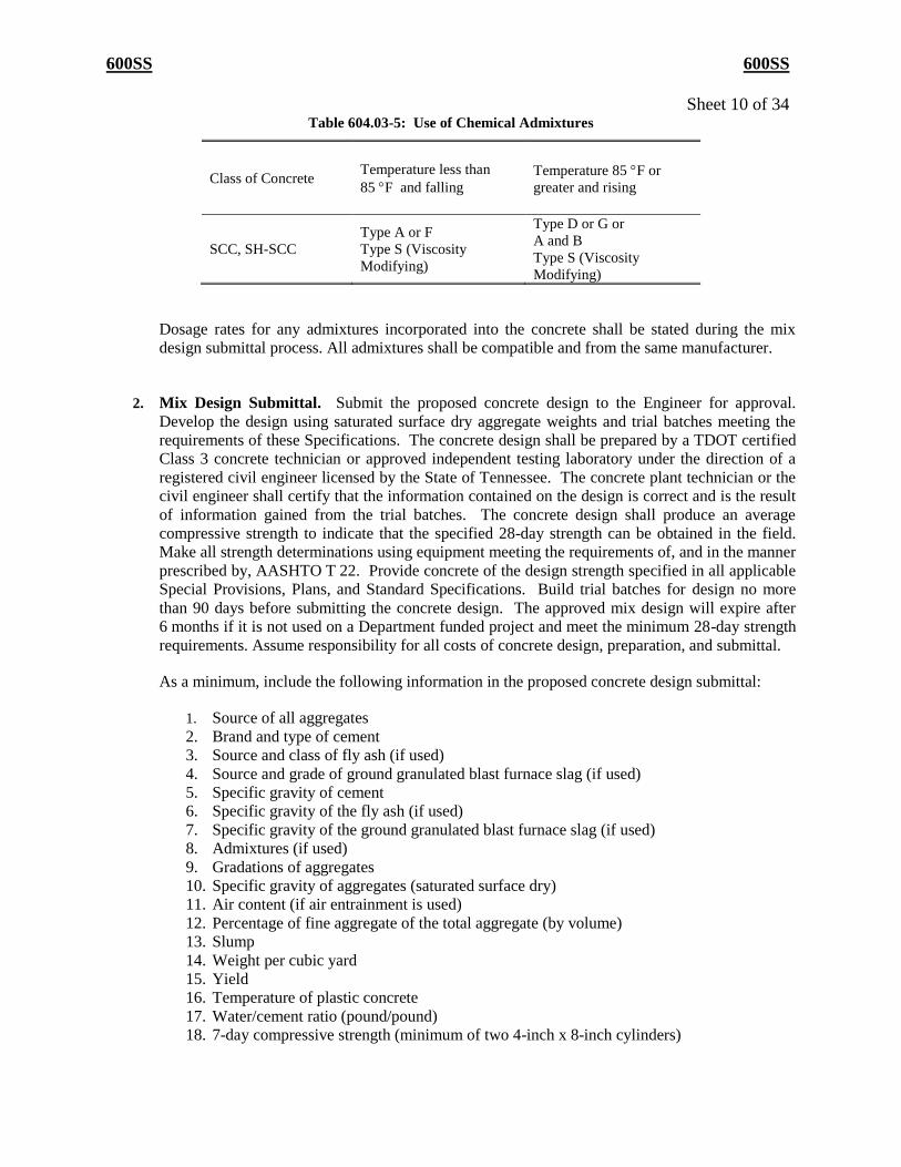
Include chemical admixtures in the self-consolidating concrete mixture as specified in Table
604.03-5 based on the ambient air temperature and expected weather conditions. Approved
viscosity modifying admixtures (VMA) may be used as part of the chemical admixtures if they
are shown in the approved mixture design.
600SS 600SS
Sheet 10 of 34 Table 604.03-5: Use of Chemical Admixtures
Class of Concrete Temperature less than
85 F and falling
Temperature 85 F or
greater and rising
SCC, SH-SCC
Type A or F
Type S (Viscosity
Modifying)
Type D or G or
A and B
Type S (Viscosity
Modifying)
Dosage rates for any admixtures incorporated into the concrete shall be stated during the mix
design submittal process. All admixtures shall be compatible and from the same manufacturer.
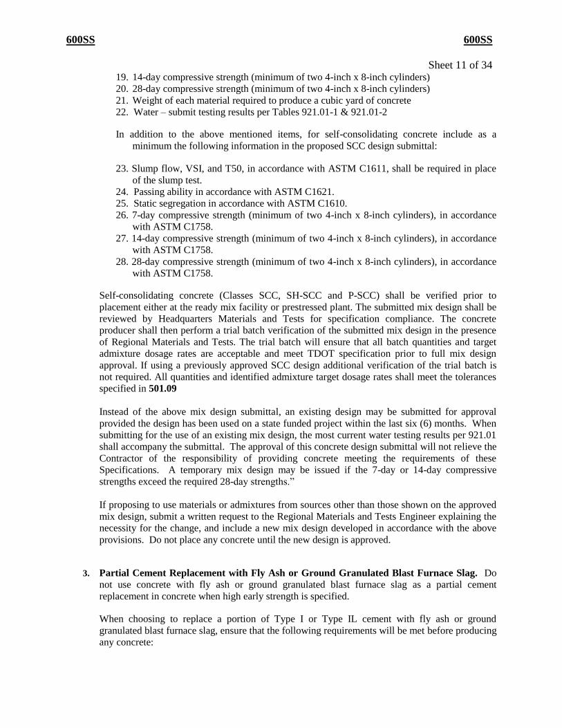
2. Mix Design Submittal. Submit the proposed concrete design to the Engineer for approval.
Develop the design using saturated surface dry aggregate weights and trial batches meeting the
requirements of these Specifications. The concrete design shall be prepared by a TDOT certified
Class 3 concrete technician or approved independent testing laboratory under the direction of a
registered civil engineer licensed by the State of Tennessee. The concrete plant technician or the
civil engineer shall certify that the information contained on the design is correct and is the result
of information gained from the trial batches. The concrete design shall produce an average
compressive strength to indicate that the specified 28-day strength can be obtained in the field.
Make all strength determinations using equipment meeting the requirements of, and in the manner
prescribed by, AASHTO T 22. Provide concrete of the design strength specified in all applicable
Special Provisions, Plans, and Standard Specifications. Build trial batches for design no more
than 90 days before submitting the concrete design. The approved mix design will expire after
6 months if it is not used on a Department funded project and meet the minimum 28-day strength
requirements. Assume responsibility for all costs of concrete design, preparation, and submittal.
As a minimum, include the following information in the proposed concrete design submittal:
1. Source of all aggregates
2. Brand and type of cement
3. Source and class of fly ash (if used)
4. Source and grade of ground granulated blast furnace slag (if used)
5. Specific gravity of cement
6. Specific gravity of the fly ash (if used)
7. Specific gravity of the ground granulated blast furnace slag (if used)
8. Admixtures (if used)
9. Gradations of aggregates
10. Specific gravity of aggregates (saturated surface dry)
11. Air content (if air entrainment is used)
12. Percentage of fine aggregate of the total aggregate (by volume)
13. Slump
14. Weight per cubic yard
15. Yield
16. Temperature of plastic concrete
17. Water/cement ratio (pound/pound)
18. 7-day compressive strength (minimum of two 4-inch x 8-inch cylinders)
600SS 600SS
Sheet 11 of 34 19. 14-day compressive strength (minimum of two 4-inch x 8-inch cylinders)
20. 28-day compressive strength (minimum of two 4-inch x 8-inch cylinders)
21. Weight of each material required to produce a cubic yard of concrete
22. Water – submit testing results per Tables 921.01-1 & 921.01-2
In addition to the above mentioned items, for self-consolidating concrete include as a
minimum the following information in the proposed SCC design submittal:
23. Slump flow, VSI, and T50, in accordance with ASTM C1611, shall be required in place
of the slump test.
24. Passing ability in accordance with ASTM C1621.
25. Static segregation in accordance with ASTM C1610.
26. 7-day compressive strength (minimum of two 4-inch x 8-inch cylinders), in accordance
with ASTM C1758.
27. 14-day compressive strength (minimum of two 4-inch x 8-inch cylinders), in accordance
with ASTM C1758.
28. 28-day compressive strength (minimum of two 4-inch x 8-inch cylinders), in accordance
with ASTM C1758.
Self-consolidating concrete (Classes SCC, SH-SCC and P-SCC) shall be verified prior to
placement either at the ready mix facility or prestressed plant. The submitted mix design shall be
reviewed by Headquarters Materials and Tests for specification compliance. The concrete
producer shall then perform a trial batch verification of the submitted mix design in the presence
of Regional Materials and Tests. The trial batch will ensure that all batch quantities and target
admixture dosage rates are acceptable and meet TDOT specification prior to full mix design
approval. If using a previously approved SCC design additional verification of the trial batch is
not required. All quantities and identified admixture target dosage rates shall meet the tolerances
specified in 501.09
Instead of the above mix design submittal, an existing design may be submitted for approval
provided the design has been used on a state funded project within the last six (6) months. When
submitting for the use of an existing mix design, the most current water testing results per 921.01
shall accompany the submittal. The approval of this concrete design submittal will not relieve the
Contractor of the responsibility of providing concrete meeting the requirements of these
Specifications. A temporary mix design may be issued if the 7-day or 14-day compressive
strengths exceed the required 28-day strengths.”
If proposing to use materials or admixtures from sources other than those shown on the approved
mix design, submit a written request to the Regional Materials and Tests Engineer explaining the
necessity for the change, and include a new mix design developed in accordance with the above
provisions. Do not place any concrete until the new design is approved.
3. Partial Cement Replacement with Fly Ash or Ground Granulated Blast Furnace Slag. Do
not use concrete with fly ash or ground granulated blast furnace slag as a partial cement
replacement in concrete when high early strength is specified.
When choosing to replace a portion of Type I or Type IL cement with fly ash or ground
granulated blast furnace slag, ensure that the following requirements will be met before producing
any concrete:

600SS 600SS
Sheet 12 of 34 1. Store fly ash or ground granulated blast furnace slag in silos separate from each other and
separate from the hydraulic cement.
2. Add the fly ash or ground granulated blast furnace slag to the concrete using methods and
equipment that are approved by the Engineer and capable of uniformly distributing the
materials throughout the mix.
3. The fly ash or ground granulated blast furnace slag may be weighed cumulatively in the
weigh hopper with the cement, provided the cement is added first. The temperature of the fly
ash or the ground granulated blast furnace slag shall not exceed 160 F at the time of
introduction to the mix.
When designing Portland cement concrete with Type I or Type IL cement modified by the
addition of fly ash and/or ground granulated blast furnace slag, meet the maximum cement
replacement rates (by weight) and minimum substitution ratios (by weight) specified in Table
604.03-3 for the applicable type of modifier.
Table 604.03-3: Type I or Type IL Cement Modified by Fly Ash or
Ground Granulated Blast Furnace Slag (GGBFS)
Modifier
Maximum Cement
Replacement Rate
% (by weight)
Minimum Modifier
Cement
Substitution Rates
(by weight)
GGBFS (grade 100
or 120)
35.0 1:1
Class “F” Fly Ash 25.0 1:1
Class “C” Fly Ash 25.0 1:1
The Contractor may use ternary cementitious mixtures (mixtures with Portland cement, ground
granulated blast furnace slag, and fly ash) for Class A, Class D, and Class DS concrete provided
that the minimum Portland cement content is 50%. The maximum amount of fly ash substitution
in a ternary cementitious mixture shall be 20%. The Department will allow Type IS cement with
ternary cementitious mixtures. When using a Type IS cement, do not use any additional slag as a
partial replacement for the hydraulic cement.
B. Quality Control and Acceptance of Concrete
Meet the requirements of 501.03.B.
In addition, the Department will require an approved concrete design for non-critical items involving
small quantities of concrete, but may accept these non-critical items at a reduced testing frequency in
accordance with Department Procedures. This requirement applies to sidewalks, curbs and gutters,
building foundations, slope paving, ditch paving, guardrail anchorages, small culvert headwalls 30
inches in diameter or less, fence posts, catch basins, manhole bases and inlets, small sign bases, and
steel strain pole footings. The Contractor may use pre-approved, pre-packaged concrete mixtures for
these applications if the quantity does not exceed 2 cubic yards per day, in which case no design will
be required. If the quantity exceeds 2 cubic yards, prior approval must be obtained from the Engineer
prior to placement.
600SS 600SS
Sheet 13 of 34 Correct batch weights to compensate for surface moisture on the aggregate at the time of use. The
Contractor may withhold some of the water from the mix at the plant and add it at the placement site
as specified in 604.13.
The Department will perform all acceptance testing and independent assurance sampling and testing
in accordance with 501.03.B.
C. High Early Strength
When the Plans for structural or pavement repairs, or other type work, require high early strength
concrete, the Contractor may use Type I, Type IL, or Type III cement. If Type I or Type IL cement is
used, the minimum cement content shall be 714 pounds per cubic yard. If Type III cement is used,
the minimum cement content shall be 620 pounds per cubic yard. The Contractor may substitute high
early strength concrete, meeting these requirements, for Class A concrete when approved in writing
by the Engineer.
When electing to use high early strength concrete, use the same source and gradation of fine and
coarse aggregates as that specified for the concrete being substituted. The Department will not make
additional payment if the Contractor decides to substitute high early strength concrete for Class A
concrete. The unit price for the class of concrete for which the substitution is made shall be full
compensation for the concrete.
Subsection 604.03 A.1a (pg. 521), 5-13-19; Design and Production Parameters; Revise 6th paragraph:
Admixtures to be incorporated into the concrete shall be compatible and incorporated into the
concrete in accordance with the manufacturer’s recommendations. Concrete mixtures utilizing
multiple admixture manufacturers shall prove compatibility in accordance with the Department’s
Standard Operating Procedure 4-4.
Subsection 604.03 A.1.b (pg. 521), 5-13-19; Self-Consolidating Concrete (SCC) Design and
Production Parameters; Revise 4th paragraph:
Dosage rates for any admixtures incorporated into the concrete shall be stated during the mix design
submittal process. All admixtures shall be compatible and incorporated into the concrete in
accordance with the manufacturer’s recommendations. Concrete mixtures utilizing multiple
admixture manufacturers shall prove compatibility in accordance with the Department’s Standard
Operating Procedure 4-4.
600SS 600SS
Sheet 14 of 34 Subsection 604.03.B (pg. 524), 12-30-19; Quality Control and Acceptance of Concrete; Revise 2nd
paragraph:
In addition, the Department will require an approved concrete design for minor structures as listed in
604.11 B. non-critical items involving small quantities of concreteincluding , but may accept these
non-critical items at a reduced testing frequency in accordance with Department Procedures. This
requirement applies to sidewalks, curbs and gutters, building foundations, slope paving, ditch paving,
guardrail anchorages, small culvert headwalls 30 inches in diameter or less, fence posts, catch basins,
manhole bases and inlets, small sign bases, and steel strain pole footings. The Contractor may use
pre-approved, pre-packaged concrete mixtures listed in QPL 15 for these applications if the quantity
does not exceed 2 cubic yards per day, in which case no design will be required. If the quantity
exceeds 2 cubic yards, prior approval must be obtained from the Engineer prior to placement. All
pre-packaged concrete mixtures are required to be mixed in a mechanical concrete mixing machine
and in accordance with manufacturer’s recommendations.
Subsection 604.03 A.2 (pg. 521-523), 5-13-19; Mix Design Submittal; Revise 1st and 3rd paragraphs:
Submit the proposed concrete design to the Engineer for approval. Develop the design using saturated
surface dry aggregate weights and trial batches meeting the requirements of these Specifications. The
concrete design shall be prepared by a TDOT Certified Concrete Mix Design Technician or approved
independent testing laboratory under the direction of a registered civil engineer licensed by the State
of Tennessee. The TDOT Certified Concrete Mix Design Technician or the civil engineer shall certify
that the information contained on the design is correct and is the result of information gained from the
trial batches. The concrete design shall produce an average compressive strength to indicate that the
specified 28-day strength can be obtained in the field. Make all strength determinations using
equipment meeting the requirements of, and in the manner prescribed by, AASHTO T 22. Provide
concrete of the design strength specified in all applicable Special Provisions, Plans, and Standard
Specifications. Build trial batches for design no more than 90 days before submitting the concrete
design. The approved mix design will expire at the end of each calendar year or if it does not meet the
minimum 28-day strength requirements. Assume responsibility for all costs of concrete design,
preparation, and submittal.
Instead of the above mix design submittal, an existing design may be submitted for approval provided
the design has been approved by the Department within the current calendar year. When submitting
for the use of an existing design, the most current water testing results per 921.01 shall accompany
the submittal. The approval of this concrete design submittal will not relieve the Contractor of the
responsibility of providing concrete meeting the requirements of these Specifications. A temporary
mix design may be issued if the 7-day or 14-day compressive strengths exceed the required 28-day
strengths.
Subsection 604.04 (pg. 525-527). 5-14-18; Remove the last 3 paragraphs from page 527 and insert the
paragraphs as the 6th, 7th, and 8th paragraph of the subsection:
“604.04 Equipment
Obtain the Engineer’s approval as to the design, capacity, and mechanical condition of equipment and
tools used to handle materials and perform the work. Have the equipment on the jobsite sufficiently
ahead of the start of construction operations to be examined and approved by the Engineer. Use
600SS 600SS
Sheet 15 of 34 equipment and construction processes that have sufficient capacity to accomplish the maximum
continuous concrete placement, as governed by the construction joints shown on the Plans or as directed
by the Engineer.
Meet the requirements for batching plants specified in 501.04.A, except that when approved by the
Engineer, the requirement for storage compartments in addition to weigh bins for fine and coarse
aggregates may be waived, provided the batching tolerances specified in 501.09 are maintained.
Meet the requirements for mixers specified in 501.04.B, except that the requirement for the boom-and-
bucket attachment to the mixer will be waived.
Provide ample and satisfactory equipment for conveying concrete from the mixer to final position in the
forms. Use closed chutes or pipes when concrete is to be dumped or dropped for a distance greater than
5 feet. Where steep slopes are required, equip the chutes with baffle boards, or use chutes in short lengths
that will allow the direction of movement to be reversed.
Use vibrators of an approved type and design, and operate them under load at the rate recommended by
the manufacturer and approved by the Engineer.
When placing concrete by pumping, do not use aluminum conduit.
Do not pour any concrete for bridge decks or slabs above grade before verifying the availability and
operability of all necessary equipment, including finishing machines, continuous water source or portable
tanks, water distribution equipment, two work bridges, vibrators, sprayers, a 12-foot straightedge, and
appropriate backup items.
Provide at every concrete deck pour a portable, cold fogger capable of changing humidity and cooling air
above fresh concrete. The fogger shall be designed to provide a maximum VMD (volume mean
diameter) of 15 microns, and a throw distance of 60 feet.
The Contractor may mix concrete for minor structures, as identified in 604.11.B, in a mobile volumetric
continuous mixing plant.
Use a mobile mixing plant that is:
1. Designed to accurately batch aggregates and cement by volume based on weight.
2. Equipped to perform mixing by a continuous auger and/or paddles.
3. Capable of producing a uniform concrete mix meeting all requirements of the Specifications.
4. Capable of carrying in separate compartments all the necessary ingredients needed for the
concrete mix.
5. Equipped with calibrated proportional devices for each material.
6. Equipped with proportioning controls that they may be set and secured for different materials and
mixes.
600SS 600SS
Sheet 16 of 34 7. Equipped with separate bins and gate openings for each type of material, including a watertight
storage bin for cement. Cover the aggregate bins with tarpaulins or by other approved methods
when required.
Ensure that a metal plate identifying the discharge speed and weight-calibrated constant of the machine is
attached to each unit.
Make adequate standard volume measures, scales, and weights available for checking the accuracy of the
proportioning mechanism.
Furnish a calibrated chart for the individual unit when required by the Engineer.
In the Engineer’s presence, the producer or factory representative shall perform the calibration and gate
settings according to the manufacturer’s recommendations for the design to be used.
Provide a satisfactory method of setting the dosage for admixtures. If using admixtures other than air-
entraining agents, add them in the manner and in the dosage recommended by the manufacturer.
Subsection 604.04 (pg. 525-527); 5-13-19; Equipment; Remove 5 th-11th paragraphs, Add subsection A. title, and add subsection B:
A. General
Obtain the Engineer’s approval as to the design, capacity, and mechanical condition of equipment
and tools used to handle materials and perform the work. Have the equipment on the jobsite
sufficiently ahead of the start of construction operations to be examined and approved by the
Engineer. Use equipment and construction processes that have sufficient capacity to accomplish
the maximum continuous concrete placement, as governed by the construction joints shown on
the Plans or as directed by the Engineer.
Meet the requirements for batching plants specified in 501.04.A, except that when approved by the
Engineer, the requirement for storage compartments in addition to weigh bins for fine and coarse
aggregates maybe waived, provided the batching tolerances specified in 501.09 are maintained.
Meet the requirements for mixers specified in 501.04.B, except that the requirement for the
boom-and-bucket attachment to the mixer will be waived.
Provide ample and satisfactory equipment for conveying concrete from the mixer to final position in
the forms. Use closed chutes or pipes when concrete is to be dumped or dropped for a distance
greater than 5 feet. Where steep slopes are required, equip the chutes with baffle boards, or use
chutes in short lengths that will allow the direction of movement to be reversed.
Use vibrators of an approved type and design, and operate them under load at the rate
recommended by the manufacturer and approved by the Engineer.
When placing concrete by pumping, do not use aluminum conduit.
Do not pour any concrete for bridge decks or slabs above grade before verifying the availability
and operability of all necessary equipment, including finishing machines, continuous water source
600SS 600SS
Sheet 17 of 34 or portable tanks, water distribution equipment, two work bridges, vibrators, sprayers, a 12-foot
straightedge, and appropriate backup items.
Provide at every concrete deck pour a portable, cold fogger capable of changing humidity and
cooling air above fresh concrete. The fogger shall be designed to provide a maximum VMD
(volume mean diameter) of 15 microns, and a throw distance of 60 feet.
B. Volumetric Continuous Mixers
Produce concrete specified in Table 604.03-1 in accordance with Section 604.03, in a
volumetric continuous mixing plant provided that the manufacturer’s equipment meets
the tolerance requirements of Section 501.09. Use a volumetric continuous mixing plant
that conforms to the following:
1. The unit shall be equipped with:
a) Calibrated proportioning devices for each ingredient added to the concrete mix and
perform mixing by a continuous auger and/or paddles.
b) Equipped with proportioning controls that may be set and secured for different materials
and mixes.
c) A working recording meter that is visible at all times and furnishes a ticket printout with
the calibrated measurement of the mix being produced.
d) Separate bins and gate openings for each type of material, including a watertight storage
bin for cement. Cover the aggregate bins with tarpaulins or by other approved methods
when required.
2. The unit shall have a stamped plate from the Volumetric Mixer Manufacturers Bureau
(VMMB) stating the equipment conforms to ASTM C685. The plate shall be attached in a
prominent place and have the following plainly marked: the gross volume of the transportation
unit in terms of mixed concrete, the discharge speed, and the mass calibrated constant of the
machine in terms of volume.
3. The calibration will be performed in the presence of the Engineer by a Volumetric Mixer
Operator certified by VMMB and holds a TDOT Concrete Mix Design Technician
Certification. Perform the calibration of gate settings according to the manufacturer’s
recommendations for the mix design to be used. Inspections and calibrations shall be performed
at a minimum of every 6 months, every 2500 cubic yards, or when a new mix design is to be
used. The yield shall be maintained within a tolerance of ±1 percent and verified using a
minimum 2 cubic feet container every 500 cubic yards or a minimum of once per week.
4. The volumetric mixing plant shall be operated by a Volumetric Mixer Operator certified by
VMMB and holds a TDOT Concrete Plant Quality Control Technician Certification. Any
equipment adjustment that would cause any deviation from the approved concrete mix design
shall not be made during the on-site production of concrete.
600SS 600SS
Sheet 18 of 34 If the mixer fails to discharge a uniform mix at any time, production of concrete shall halt until any
problems are corrected.
Each load of concrete produced by a volumetric continuous mixing plant shall be accompanied by a
Concrete Delivery Ticket. The ticket shall include as a minimum the following:
a. Date
b. Contract number
c. County
d. Class of concrete
e. Concrete design number
f. Number of cubic yards
g. Load number
h. Truck number
i. Maximum water allowed by design
j. Total water added
k. Time loaded
l. Time discharged
m. Signature of producer’s TDOT Certified Concrete Plant Quality Control
Technician.
The form shall be delivered to the Inspector at the site of the work. Loads that do not carry such
information or do not arrive in satisfactory condition shall not be used.
Subsection 604.04 B (pg. 525-527), 12-30-19; Volumetric Continuous Mixers; Revise No. 3 & 4, add No. 5, add paragraph after No 5, revise delivery ticket list k, l, m, & add n:
A. Volumetric Continuous Mixers
….
3. The volumetric mixing plant shall be operated and calibrated by a Volumetric Mixer
Operator certified by VMMB and holds a TDOT Concrete Field Testing Technician
Certification or equivalent. In the presence of the Engineer, perform the calibration of gate
settings according to the manufacturer’s recommendations for the mix design to be used
before starting work. The calibration procedure shall account for the moisture content of the
aggregates. The yield shall be maintained within a tolerance of ±1% and verified using a
minimum 2 cubic feet container every 500 cubic yards or a minimum of once per week.The
calibration will be performed in the presence of the Engineer by a Volumetric Mixer
Operator certified by VMMB and holds a TDOT Concrete Mix Design Technician
Certification. Perform the calibration of gate settings according to the manufacturer’s
recommendations for the mix design to be used. Inspections and Recalibrations shall be
necessary when indicated by the yield checks, performed at a minimum of every 6 months,
every 2500 cubic yards, or at any time the Engineer deems necessary to ensure proper
proportioning of the materials. when a new mix design is to be used. The yield shall be
600SS 600SS
Sheet 19 of 34 maintained within a tolerance of ±1 percent and verified using a minimum 2 cubic feet
container every 500 cubic yards or a minimum of once per week.
4. Tests for aggregate moisture contents and gradations shall be performed by someone who
holds a TDOT Concrete Plant quality Control Technician Certification or a TDOT
Aggregate Technician Certification.The volumetric mixing plant shall be operated by a
Volumetric Mixer Operator certified by VMMB and holds a TDOT Concrete Plant Quality
Control Technician Certification. Any equipment adjustment that would cause any
deviation from the approved concrete mix design shall not be made during the on-site
production of concrete.
5. A TDOT Concrete Mix Design Technician or a registered Professional Engineer licensed by
the State of Tennessee shall submit the Department in writing a concrete design in
accordance with SOP 4-4.
If the mixer fails to discharge a uniform mix at any time, production of concrete shall halt until
any problems are corrected.
Each load of concrete produced by a volumetric continuous mixing plant shall be accompanied
by a Concrete Delivery Ticket. The ticket shall include as a minimum the following:
a. Date
b. Contract number
c. County
d. Class of concrete
e. Concrete design number
f. Number of cubic yards
g. Load number
h. Truck number
i. Maximum water allowed by design
j. Total water added
k. Time loadedWater-cementitious materials ratio
l. Time loadeddischarged
m. Signature of producer’s TDOT Certified Concrete Plant Quality Control
Technician.Time discharged
n. Signature of producer’s VMMB Certified Volumetric Mixer Operator
600SS 600SS
Sheet 20 of 34 Subsection 604.11 A & B (pg. 539,540), 12-30-19; Major Structures & Minor Structures; Revise 2nd
paragraph of A & Revise paragraph of B:
A. Major Structures
…….
When using lightweight aggregates, uniformly pre-saturate the aggregates by sprinkling and
allow to drain. At time of use, ensure that the aggregates are in a saturated surface dry condition
to minimize water absorption.
B. Minor Structures
For the following items of construction, the Contractor may substitute a mobile volumetric
continuous mixing concrete plant, meeting the requirements of 604.04, for the method specified
in 501.09.
The following are considered minor structures. See each Section for additional details:
611 Manholes, catchbasins, inlets, and pipe end walls
701 Cement concrete sidewalks, driveways and median pavement
702 Cement concrete curb, gutter, and combined curb and gutter
703 Cement concrete ditch paving
705 Guard rail
707 Fences
709 Rip-rap slope paving
713 Highway signing
714 Roadway and structure lighting
Subsection 604.13 (pg. 541), 5-15-17; Mixing Concrete, add Class DS concrete to the 2nd paragraph, 3rd sentence:
D. “Do not retemper concrete by adding water or by other means. However, the Contractor may
withhold a portion of the mixing water or chemical admixtures from transit mixers and add at the
work site if all requirements of the approved mix design are met. Water added at the placement site
for Class A, Class D, Class DS and Class L concrete shall not exceed 1 gallon per cubic yard. The
total amount of water in the mix shall not exceed the maximum in the approved mix design. To
achieve additional slump, use a water reducing admixture. If water, air entrainers, or chemical
admixtures are added at the placement site, mix the concrete a minimum of 30 revolutions at mixing
speed after making the additions. Do not use concrete that is not within the specified slump limits, air
content limits, temperature limits, or time limits at the time of placement.”
Subsection 604.13 (pg. 541), 5-14-18; Mixing Concrete, revise the 2nd and 3rd sentence of the 2nd paragraph:
“Do not retemper concrete by adding water or by other means. However, the Contractor may
withhold a portion of the mixing water or chemical admixtures from transit mixers and add at the
work site if all requirements of the approved mix design are met, provided the delivery ticket
indicates the amount of water withheld. The total amount of water in the mix shall not exceed the
600SS 600SS
Sheet 21 of 34 maximum in the approved mix design. To achieve additional slump, use a water reducing
admixture. If water, air entrainers, or chemical admixtures are added at the placement site, mix
the concrete a minimum of 30 revolutions at mixing speed after making the additions. Do not use
concrete that is not within the specified slump limits, air content limits, temperature limits, or
time limits at the time of placement.”
Subsection 604.13 (pg. 541-542), 12-30-19; Quality Control and Acceptance of Concrete; Remove 4th
& 5th paragraph:
When concrete placed in the items of construction specified in 604.11.B does not exceed 25 cubic
yards per week, the Engineer may accept it on the basis of field testing for air, slump, and occasional
strength tests with only random plant inspections as deemed necessary by the Engineer for control.
When the Engineer uses this basis of acceptance, the ready-mix plant furnishing the concrete shall
have been inspected and approved for use as specified in 604.04. In addition, ensure that the delivery
ticket accompanying each load of concrete shows the class of concrete, the quantity of cement,
aggregates, water, and additives used in the batch, and the time of batching. Ensure that the materials
used in the concrete are tested and approved.
Subsection 604.14 (pg. 542), 11-16-15; Consistency of Concrete, modify the following:
“The slump of the concrete when measured according to AASHTO T 119 shall meet 604.03 - 1A.
The slump flow of self-consolidating concrete when measured according to ASTM C1611 shall
meet 604.03 1B.”
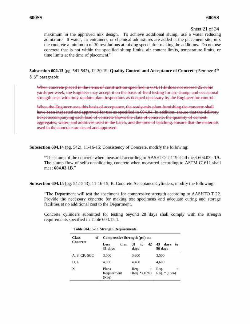
Subsection 604.15 (pg. 542-543), 11-16-15; B. Concrete Acceptance Cylinders, modify the following:
“The Department will test the specimens for compressive strength according to AASHTO T 22.
Provide the necessary concrete for making test specimens and adequate curing and storage
facilities at no additional cost to the Department.
Concrete cylinders submitted for testing beyond 28 days shall comply with the strength
requirements specified in Table 604.15-1.
Table 604.15-1: Strength Requirements
Class of
Concrete
Compressive Strength (psi) at:
Less than
31 days
31 to 42
days
43 days to
56 days
A, S, CP, SCC 3,000 3,300 3,500
D, L 4,000 4,400 4,600
X Plans
Requirement
(Req)
Req. +
Req. * (10%)
Req. +
Req. * (15%)
600SS 600SS
Sheet 22 of 34 If the acceptance cylinders fail to meet the specified strengths, the Contractor may drill core
samples from the hardened concrete as verification of concrete strength instead of using the
concrete cylinders. The Contractor must provide QC data from companion cylinders that meet or
exceed the required strength, and TDOT Materials and Test shall perform a nondestructive test
using a Swiss Hammer on the concrete to prove required strength is achieved. If the above
mentioned requirements are met, the Contractor may then elect to drill a maximum of three core
samples per set of cylinders from the hardened concrete. The Contractor shall obtain the cores in
accordance with the Department’s Standard Operating Procedure 4-2, and bear all costs of
obtaining the cores and repairing the core holes.”
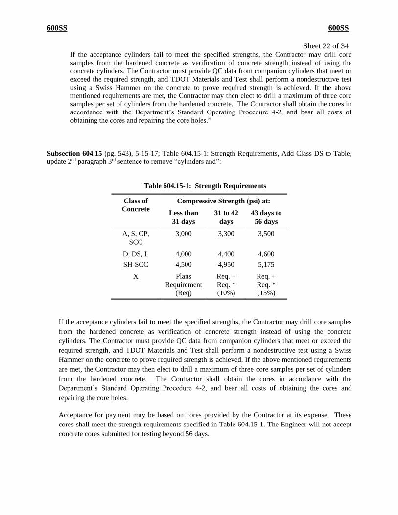
Subsection 604.15 (pg. 543), 5-15-17; Table 604.15-1: Strength Requirements, Add Class DS to Table,
update 2nd paragraph 3rd sentence to remove “cylinders and”:
Table 604.15-1: Strength Requirements
Class of
Concrete
Compressive Strength (psi) at:
Less than
31 days
31 to 42
days
43 days to
56 days
A, S, CP,
SCC
3,000 3,300 3,500
D, DS, L
SH-SCC
4,000
4,500
4,400
4,950
4,600
5,175
X Plans
Requirement
(Req)
Req. +
Req. *
(10%)
Req. +
Req. *
(15%)
If the acceptance cylinders fail to meet the specified strengths, the Contractor may drill core samples
from the hardened concrete as verification of concrete strength instead of using the concrete
cylinders. The Contractor must provide QC data from companion cylinders that meet or exceed the
required strength, and TDOT Materials and Test shall perform a nondestructive test using a Swiss
Hammer on the concrete to prove required strength is achieved. If the above mentioned requirements
are met, the Contractor may then elect to drill a maximum of three core samples per set of cylinders
from the hardened concrete. The Contractor shall obtain the cores in accordance with the
Department’s Standard Operating Procedure 4-2, and bear all costs of obtaining the cores and
repairing the core holes.
Acceptance for payment may be based on cores provided by the Contractor at its expense. These
cores shall meet the strength requirements specified in Table 604.15-1. The Engineer will not accept
concrete cores submitted for testing beyond 56 days.
600SS 600SS
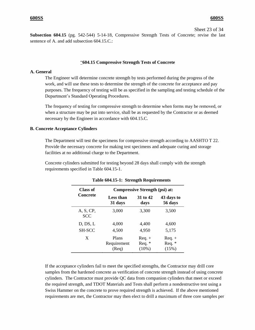
Sheet 23 of 34 Subsection 604.15 (pg. 542-544) 5-14-18, Compressive Strength Tests of Concrete; revise the last
sentence of A. and add subsection 604.15.C.:
“604.15 Compressive Strength Tests of Concrete
A. General
The Engineer will determine concrete strength by tests performed during the progress of the
work, and will use these tests to determine the strength of the concrete for acceptance and pay
purposes. The frequency of testing will be as specified in the sampling and testing schedule of the
Department’s Standard Operating Procedures.
The frequency of testing for compressive strength to determine when forms may be removed, or
when a structure may be put into service, shall be as requested by the Contractor or as deemed
necessary by the Engineer in accordance with 604.15.C.
B. Concrete Acceptance Cylinders
The Department will test the specimens for compressive strength according to AASHTO T 22.
Provide the necessary concrete for making test specimens and adequate curing and storage
facilities at no additional charge to the Department.
Concrete cylinders submitted for testing beyond 28 days shall comply with the strength
requirements specified in Table 604.15-1.
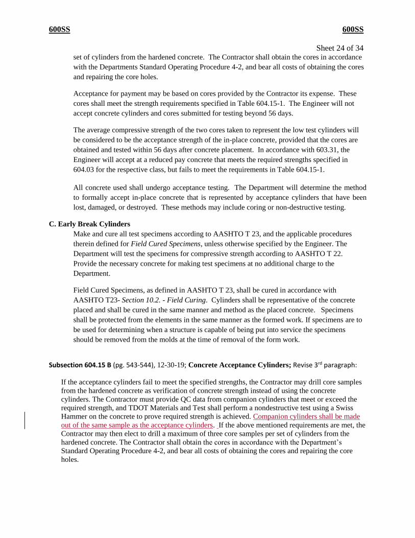
Table 604.15-1: Strength Requirements
Class of
Concrete
Compressive Strength (psi) at:
Less than
31 days
31 to 42
days
43 days to
56 days
A, S, CP,
SCC
3,000 3,300 3,500
D, DS, L
SH-SCC
4,000
4,500
4,400
4,950
4,600
5,175
X Plans
Requirement
(Req)
Req. +
Req. *
(10%)
Req. +
Req. *
(15%)
If the acceptance cylinders fail to meet the specified strengths, the Contractor may drill core
samples from the hardened concrete as verification of concrete strength instead of using concrete
cylinders. The Contractor must provide QC data from companion cylinders that meet or exceed
the required strength, and TDOT Materials and Tests shall perform a nondestructive test using a
Swiss Hammer on the concrete to prove required strength is achieved. If the above mentioned
requirements are met, the Contractor may then elect to drill a maximum of three core samples per
600SS 600SS
Sheet 24 of 34 set of cylinders from the hardened concrete. The Contractor shall obtain the cores in accordance
with the Departments Standard Operating Procedure 4-2, and bear all costs of obtaining the cores
and repairing the core holes.
Acceptance for payment may be based on cores provided by the Contractor its expense. These
cores shall meet the strength requirements specified in Table 604.15-1. The Engineer will not
accept concrete cylinders and cores submitted for testing beyond 56 days.
The average compressive strength of the two cores taken to represent the low test cylinders will
be considered to be the acceptance strength of the in-place concrete, provided that the cores are
obtained and tested within 56 days after concrete placement. In accordance with 603.31, the
Engineer will accept at a reduced pay concrete that meets the required strengths specified in
604.03 for the respective class, but fails to meet the requirements in Table 604.15-1.
All concrete used shall undergo acceptance testing. The Department will determine the method
to formally accept in-place concrete that is represented by acceptance cylinders that have been
lost, damaged, or destroyed. These methods may include coring or non-destructive testing.
C. Early Break Cylinders
Make and cure all test specimens according to AASHTO T 23, and the applicable procedures
therein defined for Field Cured Specimens, unless otherwise specified by the Engineer. The
Department will test the specimens for compressive strength according to AASHTO T 22.
Provide the necessary concrete for making test specimens at no additional charge to the
Department.
Field Cured Specimens, as defined in AASHTO T 23, shall be cured in accordance with
AASHTO T23- Section 10.2. - Field Curing. Cylinders shall be representative of the concrete
placed and shall be cured in the same manner and method as the placed concrete. Specimens
shall be protected from the elements in the same manner as the formed work. If specimens are to
be used for determining when a structure is capable of being put into service the specimens
should be removed from the molds at the time of removal of the form work.
Subsection 604.15 B (pg. 543-544), 12-30-19; Concrete Acceptance Cylinders; Revise 3rd paragraph:
If the acceptance cylinders fail to meet the specified strengths, the Contractor may drill core samples
from the hardened concrete as verification of concrete strength instead of using the concrete
cylinders. The Contractor must provide QC data from companion cylinders that meet or exceed the
required strength, and TDOT Materials and Test shall perform a nondestructive test using a Swiss
Hammer on the concrete to prove required strength is achieved. Companion cylinders shall be made
out of the same sample as the acceptance cylinders. If the above mentioned requirements are met, the
Contractor may then elect to drill a maximum of three core samples per set of cylinders from the
hardened concrete. The Contractor shall obtain the cores in accordance with the Department’s
Standard Operating Procedure 4-2, and bear all costs of obtaining the cores and repairing the core
holes.
600SS 600SS
Sheet 25 of 34
Subsection 604.16 (pg. 545) 5-15-17; Placing Concrete, A. General – revise the 1st paragraph to add
Class DS in the first sentence:
“Unless otherwise specified, before placing a bridge deck overlay of Class D , Class DS, or Class
L concrete, machine scarify the surface to be covered to a minimum depth of 1 inch. In areas
inaccessible to machine scarifying, and in areas of spalling where steel reinforcement is exposed,
remove deteriorated concrete using hand tools or other methods approved by the Engineer. After
scarifying, clean the deck of all deleterious material. Do not allow traffic on the scarified deck.”
Subsection 604.19 (pg. 551-552), 5-14-18; Removal of Forms and Falsework, Revise the 3rd paragraph
and 1. to incorporate references to subsection 604.15:
“The Contractor may release and remove falsework and supports under concrete structures
when the following conditions are met:
1. Representative specimens of the concrete, made and cured in accordance with
604.15.C, attain a compressive strength of 3000 pounds per square inch.”
Subsection 604.23 B (pg. 559), 5-13-19; Water Method; Revise 1st paragraph:
As soon as possible after applying curing compound to bridge decks and to other top slabs
located above subgrade elevation, apply either a combination of damp burlap and white
polyethylene sheeting or a white, co-polymer coated, absorbent, non-woven synthetic fabric,
from a work bridge, taking care not to mar the surface of the deck. The sheeting material shall
meet the performance requirements of ASTM C171. Immediately cover all other concrete
slabs with materials suitable for use with the water cure. After placing the protective cover,
immediately apply a mist spray and keep the cover thoroughly wet with a continuously fed
soaker hose system for 120 hours.
Subsection 604.27 (pg. 560), 11-16-15; Rideability of New or Resurfaced Bridge Decks and Roadway
Approaches, A. General, revise the 1st paragraph to the following:
“On all highway sections with a posted speed greater than 40 miles per hour, the following
rideability provisions shall apply to new or resurfaced bridge decks and roadway approaches.”
Subsection 604.31 (pg. 567-568) 5-15-17; Basis of Payment, add Class DS to item and pay unit list:
604.31 Basis of Payment
The Department will pay for accepted quantities at the contract prices as follows:
600SS 600SS
Sheet 26 of 34 Item Pay Unit
Class A Concrete (Description) Cubic Yard
Class D Concrete (Description) Cubic Yard
Class DS Concrete (Description) Cubic Yard
Class L Concrete (Description) Cubic Yard
Class S Concrete (Description) Cubic Yard
Steel Bar Reinforcement Pound
Epoxy Coated Reinforcing Pound
Scarifying Square Yard
Applied Texture Finish Square Yard
Hydro-demolition Square Yard
Subsection 606.04.B.1(b) (pg. 578), 6-27-16; replace 1.b. with the following:
“(b) Except as provided in paragraph 2(b) below, develop an energy per blow in foot-pounds
not less than 250 multiplied by R, where R is the required minimum bearing resistance of the
pile in tons.”
Subsection 606.07.A. (pg. 581), 6-27-16; revise the 1st paragraph:
“Construct cast-in-place concrete piles of the design shown on the Plans and that consist of
concrete cast in drilled holes or in steel shells or pipes driven to the required bearing. Use Class
A concrete meeting 604, or use Class X concrete, as required by design, meeting 604. Provide
and place suitable casing when required to prevent caving of the hole before concrete is placed.
Subsection 607.02 A (pg. 597), 12-30-19; Materials; Add to Materials list:
Polypropylene (PP) Pipe…………………………………914.12
Steel Reinforced Thermoplastic Ribbed Pipe (SRTRP)….914.13
Subsection 607.02 B. 1 & 2 (pg. 597-598), X-XX-19; Materials; Add to Materials list:
1. Pipe Diameters from 18 through 60 inches. Provide materials meeting one of the following:
1. Class III, IV, or V concrete pipe meeting either 914.02 or AASHTO M 86.
2. Metal pipe meeting 915.02.
3. HDPE pipe meeting 914.10.
4. PVC pipe meeting 914.09.
5. PP pipe meeting 914.12.
2. Pipe Diameters Larger than 36 inches through 48 inches. Provide materials meeting one of
the following:
1. Class III, IV, or V concrete pipe meeting 914.02.

600SS 600SS
Sheet 27 of 34 2. Metal pipe meeting 915.02.
3. HDPE pipe meeting 914.10.
4. PP pipe meeting 914.12.
Subsection 607.02 D. 1 & 2 (pg. 599), 12-30-19; Materials; Add to Materials list:
1. Pipe Diameters 15 through 36 inches. Provide materials meeting one of the following:
1. Class III, IV, or V concrete pipe meeting either 914.02 or AASHTO M 86.
2. HDPE pipe meeting 914.10.
3. PVC pipe meeting 914.09.
4. PP pipe meeting 914.12.
5. SRTRP meeting 914.13.
2. Pipe Diameters Larger than 36 through 48 inches. Provide materials meeting one of the
following:
1. Class III, IV, or V concrete pipe meeting 914.02.
2. HDPE pipe meeting 914.10.
3. PP pipe meeting 914.12.
Subsection 607.07 (pg. 601), 12-30-19; Materials; Revise 6th paragraph:
HDPE, PP, SRTRP, and PVC pipe shall meet the performance requirement for soil-tightness, unless
water-tightness is specified. Install joints so that the connection of pipe sections, for a continuous
line, will be free from irregularities in the flow line.
Subsection 611.02 (pg. 620), 11-6-17; Materials, revise the last sentence of the last paragraph to remove
the mylar reference:
“After obtaining the necessary approval, furnish the Engineer an electronic reproducible design
file..”
Subsection 613.02 (pg. 633), 6-27-16; add the following section:
“Brick Paving Units …………………………………………………………………..912.05”
600SS 600SS
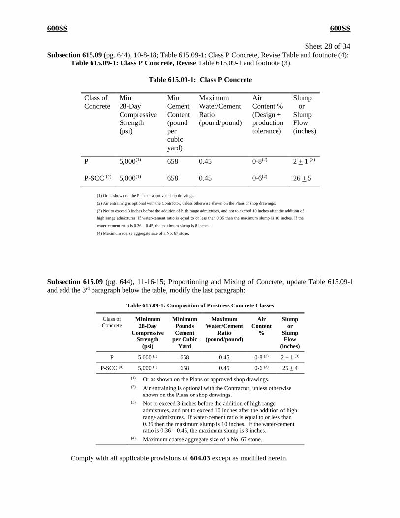
Sheet 28 of 34 Subsection 615.09 (pg. 644), 10-8-18; Table 615.09-1: Class P Concrete, Revise Table and footnote (4):
Table 615.09-1: Class P Concrete, Revise Table 615.09-1 and footnote (3).
Table 615.09-1: Class P Concrete
Class of
Concrete
Min
28-Day
Compressive
Strength
(psi)
Min
Cement
Content
(pound
per
cubic
yard)
Maximum
Water/Cement
Ratio
(pound/pound)
Air
Content %
(Design +
production
tolerance)
Slump
or
Slump
Flow
(inches)
P
5,000(1) 658 0.45 0-8(2) 2 + 1 (3)
P-SCC (4) 5,000(1) 658 0.45 0-6(2) 26 + 5
Subsection 615.09 (pg. 644), 11-16-15; Proportioning and Mixing of Concrete, update Table 615.09-1
and add the 3rd paragraph below the table, modify the last paragraph:
Table 615.09-1: Composition of Prestress Concrete Classes
Class of
Concrete Minimum
28-Day
Compressive
Strength
(psi)
Minimum
Pounds
Cement
per Cubic
Yard
Maximum
Water/Cement
Ratio
(pound/pound)
Air
Content
%
Slump
or
Slump
Flow
(inches)
P 5,000 (1) 658 0.45 0-8 (2) 2 + 1 (3)
P-SCC (4) 5,000 (1) 658 0.45 0-6 (2) 25 + 4
(1) Or as shown on the Plans or approved shop drawings.
(2) Air entraining is optional with the Contractor, unless otherwise
shown on the Plans or shop drawings.
(3) Not to exceed 3 inches before the addition of high range
admixtures, and not to exceed 10 inches after the addition of high
range admixtures. If water-cement ratio is equal to or less than
0.35 then the maximum slump is 10 inches. If the water-cement
ratio is 0.36 – 0.45, the maximum slump is 8 inches.
(4) Maximum coarse aggregate size of a No. 67 stone.
Comply with all applicable provisions of 604.03 except as modified herein.
(1) Or as shown on the Plans or approved shop drawings.
(2) Air entraining is optional with the Contractor, unless otherwise shown on the Plans or shop drawings.
(3) Not to exceed 3 inches before the addition of high range admixtures, and not to exceed 10 inches after the addition of
high range admixtures. If water-cement ratio is equal to or less than 0.35 then the maximum slump is 10 inches. If the
water-cement ratio is 0.36 – 0.45, the maximum slump is 8 inches.
(4) Maximum coarse aggregate size of a No. 67 stone.
600SS 600SS
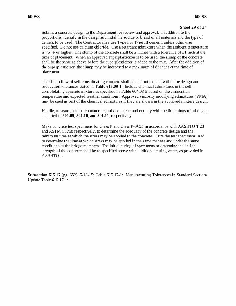
Sheet 29 of 34 Submit a concrete design to the Department for review and approval. In addition to the
proportions, identify in the design submittal the source or brand of all materials and the type of
cement to be used. The Contractor may use Type I or Type III cement, unless otherwise
specified. Do not use calcium chloride. Use a retardant admixture when the ambient temperature
is 75 F or higher. The slump of the concrete shall be 2 inches with a tolerance of ±1 inch at the
time of placement. When an approved superplasticizer is to be used, the slump of the concrete
shall be the same as above before the superplasticizer is added to the mix. After the addition of
the superplasticizer, the slump may be increased to a maximum of 8 inches at the time of
placement.
The slump flow of self-consolidating concrete shall be determined and within the design and
production tolerances stated in Table 615.09-1. Include chemical admixtures in the self-
consolidating concrete mixture as specified in Table 604.03-5 based on the ambient air
temperature and expected weather conditions. Approved viscosity modifying admixtures (VMA)
may be used as part of the chemical admixtures if they are shown in the approved mixture design.
Handle, measure, and batch materials; mix concrete; and comply with the limitations of mixing as
specified in 501.09, 501.10, and 501.11, respectively.
Make concrete test specimens for Class P and Class P-SCC, in accordance with AASHTO T 23
and ASTM C1758 respectively, to determine the adequacy of the concrete design and the
minimum time at which the stress may be applied to the concrete. Cure the test specimens used
to determine the time at which stress may be applied in the same manner and under the same
conditions as the bridge members. The initial curing of specimens to determine the design
strength of the concrete shall be as specified above with additional curing water, as provided in
AASHTO…
Subsection 615.17 (pg. 652), 5-18-15; Table 615.17-1: Manufacturing Tolerances in Standard Sections,
Update Table 615.17-1:
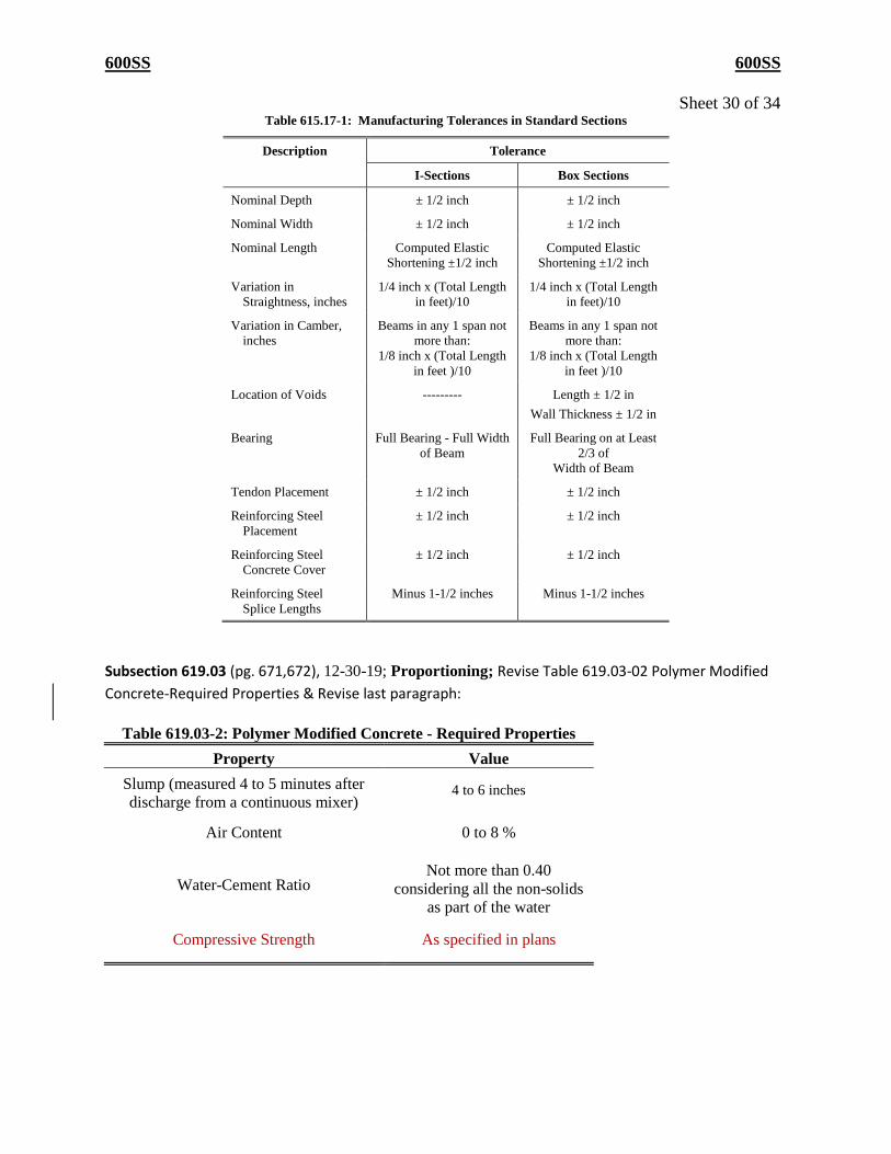
600SS 600SS
Sheet 30 of 34 Table 615.17-1: Manufacturing Tolerances in Standard Sections
Description Tolerance
I-Sections Box Sections
Nominal Depth ± 1/2 inch ± 1/2 inch
Nominal Width ± 1/2 inch ± 1/2 inch
Nominal Length Computed Elastic
Shortening ±1/2 inch
Computed Elastic
Shortening ±1/2 inch
Variation in
Straightness, inches
1/4 inch x (Total Length
in feet)/10
1/4 inch x (Total Length
in feet)/10
Variation in Camber,
inches
Beams in any 1 span not
more than:
1/8 inch x (Total Length
in feet )/10
Beams in any 1 span not
more than:
1/8 inch x (Total Length
in feet )/10
Location of Voids --------- Length ± 1/2 in
Wall Thickness ± 1/2 in
Bearing Full Bearing - Full Width
of Beam
Full Bearing on at Least
2/3 of
Width of Beam
Tendon Placement ± 1/2 inch ± 1/2 inch
Reinforcing Steel
Placement
± 1/2 inch ± 1/2 inch
Reinforcing Steel
Concrete Cover
± 1/2 inch ± 1/2 inch
Reinforcing Steel
Splice Lengths
Minus 1-1/2 inches Minus 1-1/2 inches
Subsection 619.03 (pg. 671,672), 12-30-19; Proportioning; Revise Table 619.03-02 Polymer Modified
Concrete-Required Properties & Revise last paragraph:
Table 619.03-2: Polymer Modified Concrete - Required Properties
Property Value
Slump (measured 4 to 5 minutes after
discharge from a continuous mixer) 4 to 6 inches
Air Content 0 to 8 %
Water-Cement Ratio Not more than 0.40
considering all the non-solids
as part of the water
Compressive Strength As specified in plans

600SS 600SS
Sheet 31 of 34 The polymer admixture shall contain a minimum of 46% solids. Submit to the Department in writing
a A concrete mix design is required for identifying constituent materials. the name and location of
aggregate suppliers, and the type and brand of the cement and polymer proposed for use. Do not
place any concrete before obtaining the Department’s approval of the design. Do not change
materials without the Engineer’s written approval.
Subsection 619.04 A (pg. 672-673), EFFECTIVE 01-01-21; Mixer; Revise entire subsection:
A. Volumetric Continuous Mixers
Produce PMC overlay in a volumetric continuous mixing plant provided that the
manufacturer’s equipment meets the tolerance requirements of Section 501.09.
Use a volumetric continuous mixing plant that conforms to the following:
5. The unit shall be equipped with:
e) Calibrated proportioning devices for each material added to the
concrete mix and perform mixing by a continuous auger and/or
paddles.
f) Proportioning controls that may be set and secured for different
materials and mixes.
g) Recording meter that is visible at all times and furnishes a ticket
printout with the calibrated measurement of the mix being
produced.
h) Separate bins and gate openings for each type of material,
including a watertight storage bin for cement. Cover the
aggregate bins with tarpaulins or by other approved methods
when required.
6. The unit shall have a stamped plate from the Volumetric Mixer
Manufacturers Bureau (VMMB) stating the equipment conforms to
ASTM C685. The plate shall be attached in a prominent place and
have the following plainly marked: the gross volume of the
transportation unit in terms of mixed concrete, the discharge speed,
and the mass calibrated constant of the machine in terms of
volume.
7. The volumetric mixing plant shall be operated and calibrated by a
Volumetric Mixer Operator certified by VMMB and holds a TDOT
Concrete Field Testing Technician Certification or equivalent. In
the presence of the Engineer, perform the calibration of gate
settings according to the manufacturer’s recommendations for the
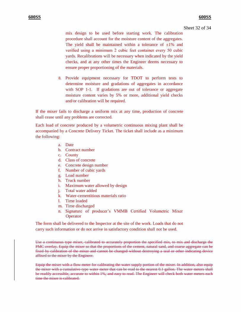
600SS 600SS
Sheet 32 of 34 mix design to be used before starting work. The calibration
procedure shall account for the moisture content of the aggregates.
The yield shall be maintained within a tolerance of ±1% and
verified using a minimum 2 cubic feet container every 50 cubic
yards. Recalibrations will be necessary when indicated by the yield
checks, and at any other times the Engineer deems necessary to
ensure proper proportioning of the materials.
8. Provide equipment necessary for TDOT to perform tests to
determine moisture and gradations of aggregates in accordance
with SOP 1-1. If gradations are out of tolerance or aggregate
moisture content varies by 5% or more, additional yield checks
and/or calibration will be required.
If the mixer fails to discharge a uniform mix at any time, production of concrete
shall cease until any problems are corrected.
Each load of concrete produced by a volumetric continuous mixing plant shall be
accompanied by a Concrete Delivery Ticket. The ticket shall include as a minimum
the following:
a. Date
b. Contract number
c. County
d. Class of concrete
e. Concrete design number
f. Number of cubic yards
g. Load number
h. Truck number
i. Maximum water allowed by design
j. Total water added
k. Water-cementitious materials ratio
l. Time loaded
m. Time discharged
n. Signature of producer’s VMMB Certified Volumetric Mixer
Operator
The form shall be delivered to the Inspector at the site of the work. Loads that do not
carry such information or do not arrive in satisfactory condition shall not be used.
Use a continuous type mixer, calibrated to accurately proportion the specified mix, to mix and discharge the
PMC overlay. Equip the mixer so that the proportions of the cement, natural sand, and coarse aggregate can be
fixed by calibration of the mixer and cannot be changed without destroying a seal or other indicating device
affixed to the mixer by the Engineer.
Equip the mixer with a flow meter for calibrating the water supply portion of the mixer. In addition, also equip
the mixer with a cumulative-type water meter that can be read to the nearest 0.1 gallon. The water meters shall
be readily accessible, accurate to within 1%, and easy to read. The Engineer will check both water meters each
time the mixer is calibrated.
600SS 600SS
Sheet 33 of 34
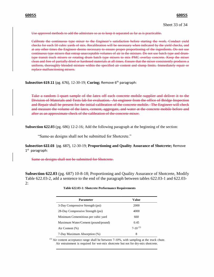
Use approved methods to add the admixture so as to keep it separated as far as is practicable.
Calibrate the continuous type mixer to the Engineer’s satisfaction before starting the work. Conduct yield
checks for each 50 cubic yards of mix. Recalibration will be necessary when indicated by the yield checks, and
at any other times the Engineer deems necessary to ensure proper proportioning of the ingredients. Do not use
continuous type mixers that entrap unacceptable volumes of air in the mixture. Do not use batch type and drum-
type transit truck mixers or rotating drum batch type mixers to mix PMC overlay concrete. Keep the mixer
clean and free of partially dried or hardened materials at all times. Ensure that the mixer consistently produces a
uniform, thoroughly blended mixture within the specified air content and slump limits. Immediately repair or
replace malfunctioning mixers.
Subsection 619.11 (pg. 676), 12-30-19; Curing; Remove 6th paragraph:
Take a random 1-quart sample of the latex off each concrete mobile supplier and deliver it to the
Division of Materials and Tests lab for evaluation. An engineer from the office of Bridge Inspection
and Repair shall be present for the initial calibration of the concrete mobile. The Engineer will check
and measure the volume of the latex, cement, aggregate, and water at the concrete mobile before and
after as an approximate check of the calibration of the concrete mixer.
Subsection 622.03 (pg. 686) 12-2-16; Add the following paragraph at the beginning of the section:
“Same-as designs shall not be submitted for Shotcrete.”
Subsection 622.03 (pg. 687), 12-30-19; Proportioning and Quality Assurance of Shotcrete; Remove 1st paragraph:
Same as designs shall not be submitted for Shotcrete.
Subsection 622.03 (pg. 687) 10-8-18; Proportioning and Quality Assurance of Shotcrete, Modify
Table 622.03-2, add a sentence to the end of the paragraph between tables 622.03-1 and 622.03-
2: Table 622.03-1: Shotcrete Performance Requirements
Parameter Value
3-Day Compressive Strength (psi) 2000
28-Day Compressive Strength (psi) 4000
Minimum Cementitious per cubic yard 660
Maximum Water/Cement (pound/pound) 0.45
Air Content (%) 7-10 (1)
7-Day Maximum Absorption (%) 8 (1) Air content acceptance range shall be between 7-10%, with sampling at the truck chute.
Air entrainment is required for wet-mix shotcrete but not for dry-mix shotcrete.
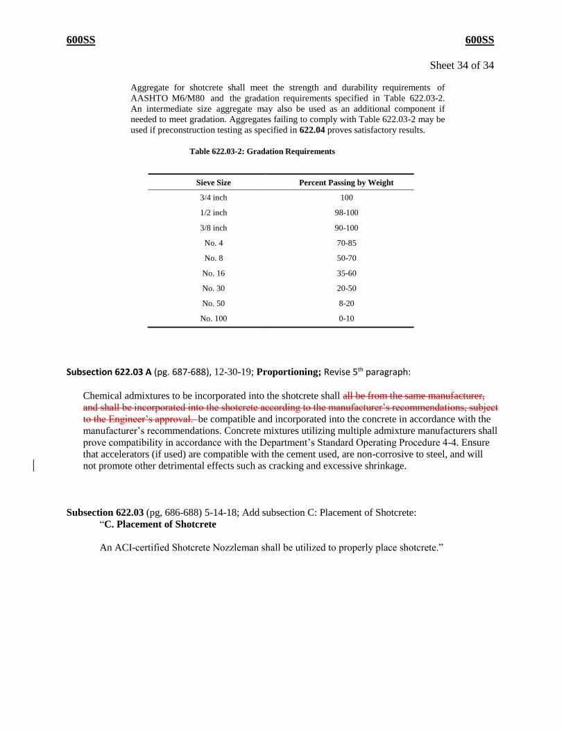
600SS 600SS
Sheet 34 of 34
Aggregate for shotcrete shall meet the strength and durability requirements of
AASHTO M6/M80 and the gradation requirements specified in Table 622.03-2.
An intermediate size aggregate may also be used as an additional component if
needed to meet gradation. Aggregates failing to comply with Table 622.03-2 may be
used if preconstruction testing as specified in 622.04 proves satisfactory results.
Table 622.03-2: Gradation Requirements
Sieve Size Percent Passing by Weight
3/4 inch 100
1/2 inch 98-100
3/8 inch 90-100
No. 4 70-85
No. 8 50-70
No. 16 35-60
No. 30 20-50
No. 50 8-20
No. 100 0-10
Subsection 622.03 A (pg. 687-688), 12-30-19; Proportioning; Revise 5th paragraph:
Chemical admixtures to be incorporated into the shotcrete shall all be from the same manufacturer,
and shall be incorporated into the shotcrete according to the manufacturer’s recommendations, subject
to the Engineer’s approval. be compatible and incorporated into the concrete in accordance with the
manufacturer’s recommendations. Concrete mixtures utilizing multiple admixture manufacturers shall
prove compatibility in accordance with the Department’s Standard Operating Procedure 4-4. Ensure
that accelerators (if used) are compatible with the cement used, are non-corrosive to steel, and will
not promote other detrimental effects such as cracking and excessive shrinkage.
Subsection 622.03 (pg, 686-688) 5-14-18; Add subsection C: Placement of Shotcrete:
“C. Placement of Shotcrete
An ACI-certified Shotcrete Nozzleman shall be utilized to properly place shotcrete.”


![1. Product Name€¦ · · 2017-06-01rating as per ASTM E 119, ... trucking fleet of 15 tractors and 40 trailers with a network of ... ASTM F3125/F3125M-[2015]](https://img.pdfslide.us/doc/110x75/5b08efd27f8b9a5f6d8d2eef/1-product-as-per-astm-e-119-trucking-fleet-of-15-tractors-and-40-trailers.jpg)