Embed Size (px)
Citation preview
S-Series MixerSanitary Stainless Steel
Portable and Fixed Mount Mixers
Indianapolis ● Chicago ● San Juan www.hollandapt.com
800-800-8464
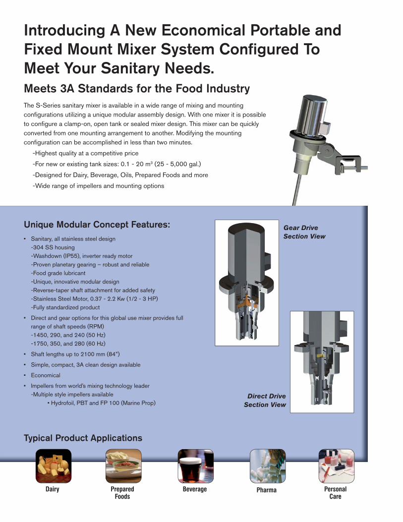
Introducing A New Economical Portable and Fixed Mount Mixer System Confi gured To Meet Your Sanitary Needs.Meets 3A Standards for the Food Industry The S-Series sanitary mixer is available in a wide range of mixing and mounting confi gurations utilizing a unique modular assembly design. With one mixer it is possible to confi gure a clamp-on, open tank or sealed mixer design. This mixer can be quickly converted from one mounting arrangement to another. Modifying the mounting confi guration can be accomplished in less than two minutes.
-Highest quality at a competitive price
-For new or existing tank sizes: 0.1 - 20 m3 (25 - 5,000 gal.)
-Designed for Dairy, Beverage, Oils, Prepared Foods and more
-Wide range of impellers and mounting options
Unique Modular Concept Features:• Sanitary, all stainless steel design -304 SS housing -Washdown (IP55), inverter ready motor -Proven planetary gearing – robust and reliable -Food grade lubricant -Unique, innovative modular design -Reverse-taper shaft attachment for added safety -Stainless Steel Motor, 0.37 - 2.2 Kw (1/2 - 3 HP) -Fully standardized product
• Direct and gear options for this global use mixer provides full range of shaft speeds (RPM) -1450, 290, and 240 (50 Hz) -1750, 350, and 280 (60 Hz)
• Shaft lengths up to 2100 mm (84”)
• Simple, compact, 3A clean design available
• Economical
• Impellers from world’s mixing technology leader -Multiple style impellers available • Hydrofoil, PBT and FP 100 (Marine Prop)
Gear DriveSection View
Direct DriveSection View
Typical Product Applications
Pharma PersonalCare
BeverageDairy PreparedFoods
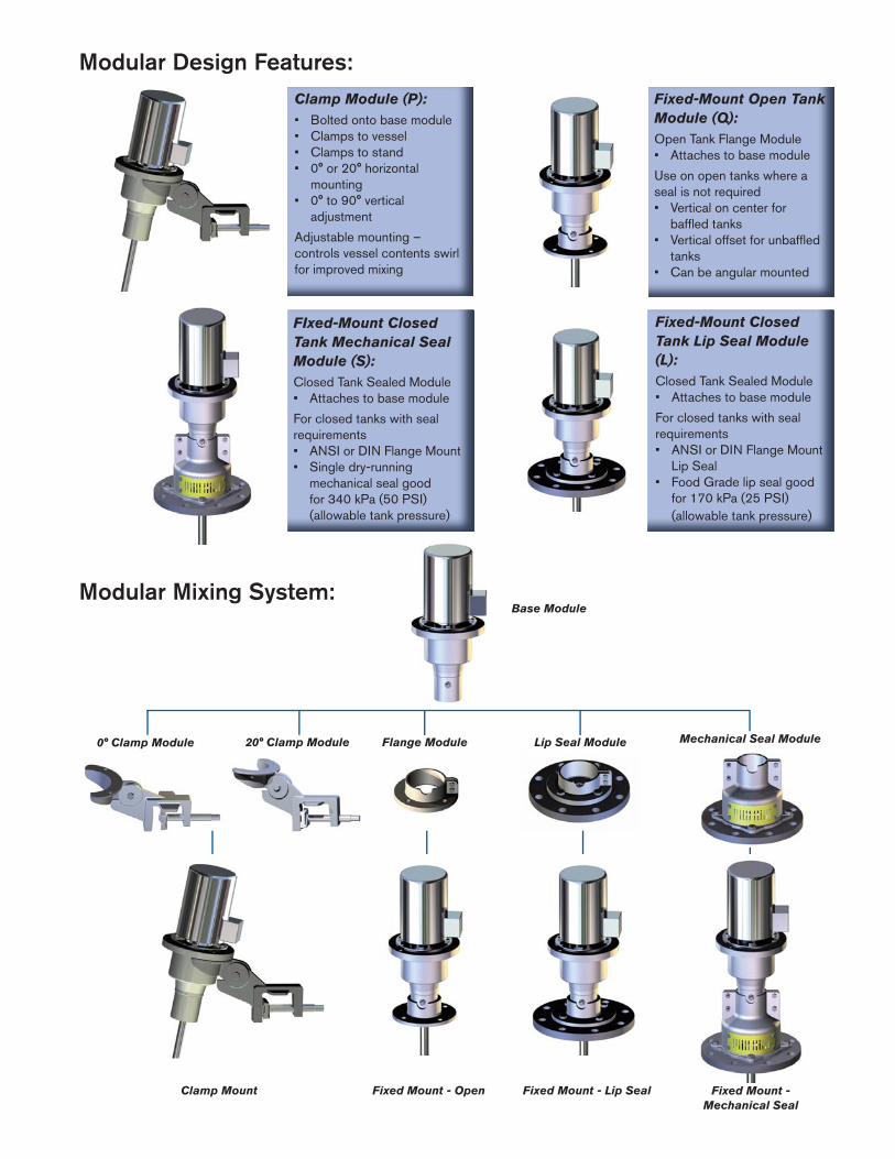
Modular Design Features:Fixed-Mount Open Tank Module (Q):Open Tank Flange Module• Attaches to base module
Use on open tanks where a seal is not required• Vertical on center for baffl ed tanks• Vertical offset for unbaffl ed tanks• Can be angular mounted
Modular Mixing System:
Clamp Module (P):• Bolted onto base module• Clamps to vessel• Clamps to stand• 0° or 20° horizontal mounting• 0° to 90° vertical adjustment
Adjustable mounting – controls vessel contents swirl for improved mixing
FIxed-Mount Closed Tank Mechanical Seal Module (S):Closed Tank Sealed Module• Attaches to base module
For closed tanks with seal requirements• ANSI or DIN Flange Mount• Single dry-running mechanical seal good for 340 kPa (50 PSI) (allowable tank pressure)
Fixed-Mount Closed Tank Lip Seal Module (L):Closed Tank Sealed Module• Attaches to base module
For closed tanks with seal requirements• ANSI or DIN Flange Mount Lip Seal• Food Grade lip seal good for 170 kPa (25 PSI) (allowable tank pressure)
Base Module
20° Clamp Module Flange Module Lip Seal Module Mechanical Seal Module0° Clamp Module
Clamp Mount Fixed Mount - Open Fixed Mount - Lip Seal Fixed Mount - Mechanical Seal

Sanitary Mixer “Blend Time Selection Table”60 HZ Selections
TAN
K V
OLU
ME
/GA
LLO
NS
VISCOSITY/cP or mPa-s
1 100 250 500 2500 5000
<25
<50
<100
<200
<500
<1000
<2000
<3000
<5000
MS1_1(1)
1 3.6 FP
MS1_1(1)
1 3.6 FP
MS1_1(2)
1 3.6 FP
MS1_1(3)
1 3.6 FP
MS1_1(6)
1 3.8 FP
MS5_1(4)
1 11.2 H
MS5_1(7)
1 11.2 H
MS6_1(11)
2 11.8 H
MS6_1(14)
2 12.8 H
1000
MS1_1(1)
1 3.6 FP
MS1_1(1)
1 3.6 FP
MS1_1(2)
1 3.6 FP
MS1_1(3)
1 3.6 FP
MS5_1(3)
1 11.2 H
MS5_1(7)
1 11.2 H
MS5_1(14)
1 11.2 H
MS6_1(16)
2 12.8 H
MS6_2(23)
2 13.6 H
MS1_1(1)
1 3.6 FP
MS1_1(2)
1 3.6 FP
MS1_1(2)
1 3.8 FP
MS5_1(1)
1 11.2 H
MS5_1(4)
1 11.2 H
MS5_1(6)
1 11.8 H
MS6_1(12)
2 12.8 H
MS6_2(18)
2 13.6 H
MS6_3(24)
2 14.5 H
MS1_1(1)
1 3.6 FP
MS1_1(2)
1 3.6 FP
MS5_1(1)
1 11.2 H
MS5_1(2)
1 11.2 H
MS5_1(5)
1 11.8 H
MS5_1(7)
1 12.8 H
MS6_2(17)
2 13.6 H
MS6_3(20)
2 14.5 H
MS6_4(27)
2 15.1 H
MS1_1(1)
1 3.3 FP
MS5_1(1)
1 10.0 H
MS5_1(2)
1 10.0 H
MS6_1(3)
2 11.2 H
MS6_1(6)
2 12.8 H
MS6_2(10)
1 13.6 H
MS6_3(22)
2 14.5 H
MS6_4(27)
2 15.1 H
MS6_4(38)
2 15.1 H
MS6_1(2)
1 8.9 FP
MS6_1(3)
1 8.9 FP
MS6_1(3)
1 10.0 FP
MS6_2(6)
2 10.5 FP
MS6_3(12)
2 13.6 H
MS6_3(21)
2 13.6 H
MS6_4(33)
2 15.1 H
MS6_5(42)
2 15.6 H
MS6_1(3)
1 7.7 FP
MS6_1(3)
1 10.0 FP
MS6_2(5)
2 10.0 FP
MS6_3(9)
2 10.5 FP
MS6_4(11)
2 11.4 FP
MS6_5(15)
2 13.1 FP
Mounting
Tank height to diameter ratio 0.8 - 1.2Liquids with Newtonian viscosity characteristicsS.G. difference of liquids <0.1Use for mild blending applicationsMaximum density 1.10 g/cm3
Maximum viscosity ratio - 10:1 (>250cP)Mixer in operation during fi lling and emptying
Legend:
Motor Code HP/kW
(0.5/0.37)
(0.75/0.55)
(1/0.75)
(1.5/1.1)
(2/1.5)
(3/2.2)
FP = FP-100, H = Hydrofoil
Drive Ratio
No.Impeller
Imp.Dia.
Imp.Type
Model Design
Blend Time
Chart Reference:
1
5
6
P
Q
L
S*
1
2
3
4
5
6
Example: MS1Q2
Series
WCB MS
*Direct Drive not available with seal.
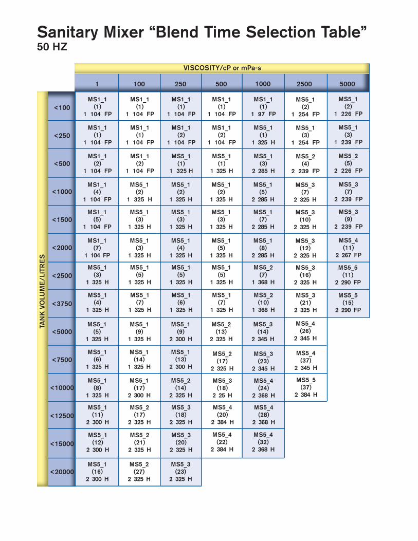
Sanitary Mixer “Blend Time Selection Table”50 HZ
TAN
K V
OLU
ME
/LIT
RE
S
VISCOSITY/cP or mPa-s
1 100 250 500 2500 5000
<100
<250
<500
<1000
<1500
<2000
<2500
<3750
<5000
<7500
<10000
<12500
<15000
<20000
MS1_1(1)
1 104 FP
MS1_1(1)
1 104 FP
MS1_1(2)
1 104 FP
MS1_1(4)
1 104 FP
MS1_1(5)
1 104 FP
MS1_1(7)
1 104 FP
MS5_1(3)
1 325 H
MS5_1(4)
1 325 H
MS5_1(5)
1 325 H
1000
MS1_1(1)
1 104 FP
MS1_1(1)
1 104 FP
MS1_1(2)
1 104 FP
MS5_1(2)
1 325 H
MS5_1(3)
1 325 H
MS5_1(3)
1 325 H
MS5_1(5)
1 325 H
MS5_1(7)
1 325 H
MS5_1(9)
1 325 H
MS1_1(1)
1 104 FP
MS1_1(2)
1 104 FP
MS5_1(1)
1 325 H
MS5_1(2)
1 325 H
MS5_1(3)
1 325 H
MS5_1(4)
1 325 H
MS5_1(5)
1 325 H
MS5_1(6)
1 325 H
MS5_1(9)
2 300 H
MS1_1(1)
1 104 FP
MS1_1(2)
1 104 FP
MS5_1(1)
1 325 H
MS5_1(2)
1 325 H
MS5_1(3)
1 325 H
MS5_1(5)
1 325 H
MS5_1(5)
1 325 H
MS5_1(7)
1 325 H
MS5_2(13)
2 325 H
MS1_1(1)
1 97 FP
MS5_1(1)
1 325 H
MS5_1(3)
2 285 H
MS5_1(5)
2 285 H
MS5_1(7)
2 285 H
MS5_1(8)
2 285 H
MS5_2(7)
1 368 H
MS5_2(10)
1 368 H
MS5_3(14)
2 345 H
MS5_1(2)
1 254 FP
MS5_1(3)
1 254 FP
MS5_2(4)
2 239 FP
MS5_3(7)
2 325 H
MS5_3(10)
2 325 H
MS5_3(12)
2 325 H
MS5_3(16)
2 325 H
MS5_3(21)
2 325 H
MS5_1(2)
1 226 FP
MS5_1(3)
1 239 FP
MS5_2(5)
2 226 FP
MS5_3(7)
2 239 FP
MS5_3(9)
2 239 FP
MS5_4(11)
2 267 FP
MS5_1(6)
1 325 H
MS5_1(8)
1 325 H
MS5_1(11)
2 300 H
MS5_1(12)
2 300 H
MS5_1(16)
2 300 H
MS5_1(14)
1 325 H
MS5_1(17)
2 300 H
MS5_2(17)
2 325 H
MS5_2(21)
2 325 H
MS5_2(27)
2 325 H
MS5_1(13)
2 300 H
MS5_2(14)
2 325 H
MS5_3(18)
2 325 H
MS5_3(20)
2 325 H
MS5_3(23)
2 325 H
MS5_2(17)
2 325 H
MS5_3(18)
2 25 H
MS5_4(20)
2 384 H
MS5_4(22)
2 384 H
MS5_3(23)
2 345 H
MS5_4(24)
2 368 H
MS5_4(28)
2 368 H
MS5_4(32)
2 368 H
MS5_4(26)
2 345 H
MS5_4(37)
2 345 H
MS5_5(37)
2 384 H
MS5_5(11)
2 290 FP
MS5_5(15)
2 290 FP

Multiple Impeller Styles:
Hydrofoil Impeller:
For low viscosity fl ow controlled applications. Combines performance and high fl ow effi ciency not found in other axial fl ow impellers.
FP 100 Impeller (Marine Prop):
Recommended for applications requiring moderate pumping action and powder-wetting capabilities.
PBT Impeller:
For low-to-medium viscosity fl ow controlled applications. Althoughsuperseded by the Hydrofoil, the PBT still has a specifi c role in applications where a degree of fl uid shear is benefi cial to the overall process result.
Service kits available for rapid replacement of routine service items:
Helical Coupling
Gear Drive Mixer Repair Kit
Sun Gear
Planetary Gear Set
Retaining Ring
Snap RingSnap Ring
Upper Bearing
Lip Seal
Snap RingLower Bearing
Lip Seal (3A Listed)
Ring Gear
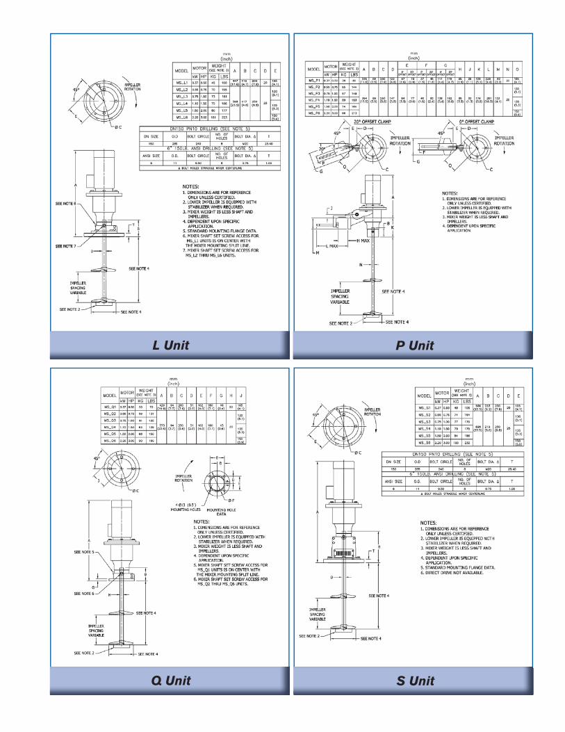
L Unit P Unit
Q Unit S Unit
SPX Process Equipment611 Sugar Creek Road, Delavan, WI 53115Phone: (262) 728-1900 or (800) 252-5200, Fax: (262) 728-4904 or (800) 252-5012E-mail: [email protected]
For more information about our worldwide locations, approvals, certifi cations, and local representatives, please visit www.spxpe.com.
SPX Corporation reserves the right to incorporate our latest design and material changes without notice or obligation.Design features, materials of construction and dimensional data, as described in this bulletin, are provided for your information only and should not be relied upon unless confi rmed in writing.
Issued: 6/2009 FH-1933 Copyright © 2009 SPX Corporation
Your local contact:
Global Headquarters:SPX Process Equipment, Delavan, WI USA
Indianapolis ● Chicago ● San Juan www.hollandapt.com
800-800-8464