Embed Size (px)
Citation preview

S-ROM® Modular Hip SystemSurgical Technique


The S-ROM® Modular Hip System offers extensive metaphyseal and diaphyseal geometries, making it versatile for a wide range of patient anatomies. The S-ROM Stem has clinical heritage dating back to 1984.
The S-ROM Modular Hip System provides solutions for a variety of surgical scenarios (from primary THA to complex revisions, and for the challenges of Development Dysplasia of the Hip) by offering the modularity of independent neck and sleeve options. The S-ROM System utilizes a straightforward surgical technique involving: 1) Distal Reaming, 2) Proximal Reaming and 3) Calcar Reaming. The streamlined S-ROM® MACH1™ Instrumentation features color-coding, instrument-implant consistency throughout and an efficient procedural flow.
This surgical technique was developed in cooperation with:
• James V. Bono, M.D. Boston, Massachusetts
• Hugh U. Cameron, M.B.Ch.B., F.R.C.S.(C). Toronto, Ontario
• Douglas A. Dennis, M.D. Denver, Colorado
• David A. Mattingly, M.D. Boston, Massachusetts
• Robert L. Buly, M.D. New York, New York
• Michael J. Christie, M.D. Nashville, Tennessee
• Wayne M. Goldstein, M.D. Chicago, Illinois
Surgical Technique S-ROM® Modular Hip System DePuy Synthes 3

IM Initiator
Open the femoral canal by penetrating the superior femoral cortex with the IM Initiator or box osteotome (not shown). To protect against varus positioning, enter the medullary canal by beginning at the posterior margin of the junction of the neck resection and the complementary cut at the trochanteric fossa.
Neck Osteotomy (90 degrees)
Perform a preliminary resection of the femoral neck using the biomechanical femoral neck resection template as a guide (not shown). The hole in the neck of the resection template is located at the center of the femoral head.
The notch on the medial aspect of the template indicates the most distal point for making the neck resection.
Step 1 – Distal Ream
Begin axial reaming with the end-cutting reamer and work up sequentially until cortical contact is achieved.
In keeping with pre-operative planning, the final straight reamer should be a half-millimeter larger than the minor distal diameter of the selected femoral stem.
The appropriate reamer depth has been established when the witness mark on each distal reamer aligns with the tip of the greater trochanter.
The diameter of the final distal reamer will dictate the color of the instrumentation selected for the remaining surgical steps.
4 DePuy Synthes S-ROM® Modular Hip System Surgical Technique
S-ROM System Surgical Technique Quick Reference

Step 3 – Calcar Ream/Mill
Select the appropriate size miller shell based on the final proximal/cone reamer utilized. Attach the appropriate color-coded pilot shaft to the distal end of the miller shell. Numeric markings of the proximal diameter are found on cone reamers and miller shells for cross reference verification.
Use the appropriate size triangle mill/drill to prepare the femur to accommodate the calcar spout of the final sleeve (S, L, or XXL).
Trial
Using the sleeve introducer, insert the appropriate trial sleeve (that matches the cone diameter and spout size reamed). Assemble the trial implant by snapping the chosen neck onto the appropriate size distal stem trial.
Introduce prior to trial reduction. The trial neck can be adjusted in 10-degree increments or “clicks”. Use the nut tightener to lock the trial when the desired version is obtained.
Mark version and remove the trials.
Final Implantation
Introduce the sleeve implant with the sleeve introducer. Place the stem introducer onto the femoral implant, and implant using the pin punch for version control. The taper is locked when the stem will no longer advance.
Step 2 – Proximal Ream
Prepare the proximal or “cone” portion of the sleeve implant.
A set of triple-banded, color-coded cone reamers are available for preparing the proximal canal. The proximal diameter of each conical reamer is marked on one side. On the opposite side, the three proximal sleeve sizes (B, D, and F) are marked with the corresponding sleeve configuration. The location of each color band moves from distal to proximal as the proximal diameter increases.
Attach the appropriate color-coded pilot shaft to the distal end of the proximal reamer, and ream until cortical contact is achieved.
Surgical Technique S-ROM® Modular Hip System DePuy Synthes 5

Preoperative Planning
Preoperative Planning Goals
Preoperative planning enables the surgeon to prepare for the case and anticipate situations that may arise during surgery. A thorough preoperative plan incorporates elements from the patient’s history, physical examination and radiographic analysis.
1. Determine preoperative leg length discrepancy
2. Assess acetabular component size and placement
3. Determine femoral component size, position and fit
4. Assess femoral offset
Radiographs
The first step in accurate templating is obtaining high-quality radiographs using a standardized protocol with known magnification. Use magnification markers attached to the patient’s leg at the level of the greater trochanter to verify magnification.
The S-ROM Modular Hip System templates (Cat. No. XRT142) incorporate 15 percent magnification.
Obtain an anterior/posterior (A/P) view of the pelvis with both extremities in 15 degrees of internal rotation to position the head and neck parallel to the coronal plane. A direct lateral radiograph should also be obtained to determine desired femoral fixation.
6 DePuy Synthes S-ROM® Modular Hip System Surgical Technique

Figure A
Figure B
Determination of Leg Length Discrepancy
To determine preoperative leg length, perform a clinical evaluation in conjunction with a radiographic analysis. Use both to determine intraoperative leg length management.
As an estimate of leg length discrepancy radiographically, draw a reference line along the inferior aspect of the ischial tuberosities (Figure A). Measure the distance from the lesser trochanter landmark to the reference line on each side. The difference between the two is the radiographic leg length discrepancy.
The tip of the greater trochanter may be used as an alternative reference mark in conjunction with the lines along the inferior aspect of the ischial tuberosities.
Acetbular Cup Size and Position
Most sizing predictions are made on the A/P radiograph of the hip. Determine the optimal position for the acetabular component and predict the size using template overlays. The acetabular teardrop can be referenced as the inferior margin of the acetabular reconstruction.
The goal in cementless acetabular fixation is to maximize bone contact. Once this is determined, mark the intended center of rotation of the bearing surface on the A/P radiograph (Figure B).
Surgical Technique S-ROM® Modular Hip System DePuy Synthes 7
Preoperative Planning

Cementless Femoral Component Selection
Select the femoral component template size that will fit the distal femur and equalize leg lengths (Figure C). The distal stem diameter determines the range of possible ZTT® Sleeves that can be used proximally. The appropriate ZTT Sleeve will allow for proximal fit and fill for stable fixation.
The femoral template should be in line with the long axis of the femur and the neck resection line drawn at the point where the selected stem provides the desired amount of leg length (Figure C). The vertical distance between the planned center of rotation of the acetabular component and the center of rotation of the femoral head constitutes the distance the leg length will be adjusted. The level of neck resection depends on the stem size and the desired leg length, with the goal of using a non-skirted modular head to optimize range of motion prior to prosthetic impingement.
A lateral radiograph should also be obtained as part of preoperative planning. To help properly position the template on the lateral radiograph, estimate the distance between the tip of the greater trochanter and the neck resection line of the stem using the A/P radiograph. Verify that the stem size chosen in the A/P plane also fits in the lateral plane. The lateral radiograph of a properly sized implant will typically exhibit appropriate fixation.
Figure C
8 DePuy Synthes S-ROM® Modular Hip System Surgical Technique
Preoperative Planning
Sleeve Selection
Overlay the ZTT Sleeve template cone size that corresponds to the selected stem and provides adequate proximal bone fill (Figure D). Position the sleeve template using the centerline of the stem, the centerline of the sleeve and the horizontal resection line. The ZTT Sleeve is estimated most accurately from the lateral endosteum (i.e., the metaphyseal A/P diameter).
Offset Requirements
The S-ROM Cementless Femoral Components are available in a range of offsets and calcar options. Through templating and intraoperative trialing, determine which option restores proper offset by matching the cup’s center of rotation with the desired head center of rotation (Figure D).
Figure D
Surgical Technique S-ROM® Modular Hip System DePuy Synthes 9
Preoperative Planning

Neck Osteotomy
With S-ROM Hip System, a higher, more conservative, perpendicular neck osteotomy may be utilized. It is recommended that preoperative templating be used to make the neck cut (Figure 1).
Additionally, a preliminary resection of the femoral neck can be performed using the biomechanical femoral neck resection template (Cat. No. 2576-00-004) as a guide (Figure 2). The hole in the neck of the resection template is located at the center of the femoral head (28mm). The notch on the medial aspect of the template indicates the most distal point for making the neck resection. The device is adjustable and can duplicate a range of lateral offsets, leg lengths and head positions. Final neck preparation can be performed later in the procedure (during calcar reaming).
Opening Canal
Open the femoral canal by penetrating the superior femoral cortex with the Intramedullary (IM) initiator (Cat. No. 2576-00-006) (Figure 3). Start the IM initiater at the junction of the neck resection and the complementary cut at the trochanteric fossa. To protect against varus positioning, the circular box osteotome (not shown) (Cat. No. 2576-00-002) can be used to remove additional bone from the medial aspect of the greater trochanter.
Figure 2Biomechanical femoral neck
resection template
Figure 3Opening the femoral canal
Figure 1Neck resection
11 DePuy Synthes S-ROM® Modular Hip System Surgical Technique
Femoral Preparation

Figure 4Distal reaming
Distal Preparation
The distal diameter determines the corresponding proximal stem diameter, which is always 5 mm larger than its distal diameter. The final distal diameter reamed will also dictate the color-coded instrumentation needed for the remainder of the case (Table 1).
Begin axial reaming with the smallest reamer in your set (8 mm for the standard set and 6 mm for the Developmental Dysplasia of the Hip (DDH) set) in conjunction with the T-handle attachment. The smallest reamer in each set is end cutting, whereas all consecutive sizes are blunt-nosed side-cutting only. Continue to ream sequentially with increasing reamer diameters until cortical contact is achieved. In keeping with preoperative planning, the final straight reamer should correspond to, or be a half millimeter larger than, the minor diameter of the selected femoral stem (Table 1). The appropriate reamer depth has been established when the witness mark on each distal reamer aligns with the tip of the greater trochanter (Figure 4).
Press-fit can be achieved when over-reaming by 0.5 mm because the distal flutes add 1.25 mm total to the specified distal stem minor diameter on sizes 13, 17 & 19 mm. Distal stem size 21 mm has a 1.5 mm total of additional flute diameter. Distal stem sizes of 7, 8, 9, & 11 mm have 1.0 mm total of additional flute diameter The 6 mm DDH distal stem has 0.75 mm of additional flute diamete (Table 1).
Caution: Before moving past any one of the final distal reamer diameters listed in Table 1, make sure you are comfortable reaching the next largest final distal reamer diameter. For example, if you distally ream past 13.5 mm, be confident that the anatomy will allow you to reach to a minimum of 15.5 mm.
TABLE 1. DISTAL REAMER SELECTION FOR STRAIGHT STEMS
Color Code Stem SizeFinal Distal
ReamerDistal Flute
Outer Diameter
Violet 6 x 12 mm 6 or 6.5 mm 6.75 mm
Violet 7 x 12 mm 7 or 7.5 mm 8 mm
Silver 8 x 14 mm 8 or 8.5 mm 9 mm
Silver 9 x 14 mm 9 or 9.5 mm 10 mm
Gold 11 x 16 mm 11 or 11.5 mm 12 mm
Green 13 x 18 mm 13.5 mm 14.25 mm
Blue 15 x 20 mm 15.5 mm 16.25 mm
Black 17 x 22 mm 17.5 mm 18.25 mm
Brown 19 x 24 mm 19.5 mm 20.25 mm
Silver 21 x 26 mm 21.5 or 22 mm 22.5 mm
Reamer line goes to level of the greater trochanter
Surgical Technique S-ROM® Modular Hip System DePuy Synthes 11
Distal Ream – Step 1
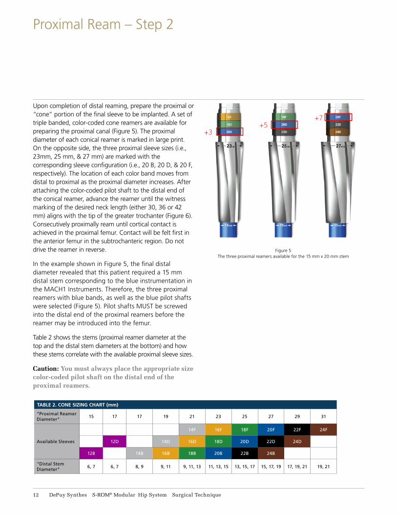
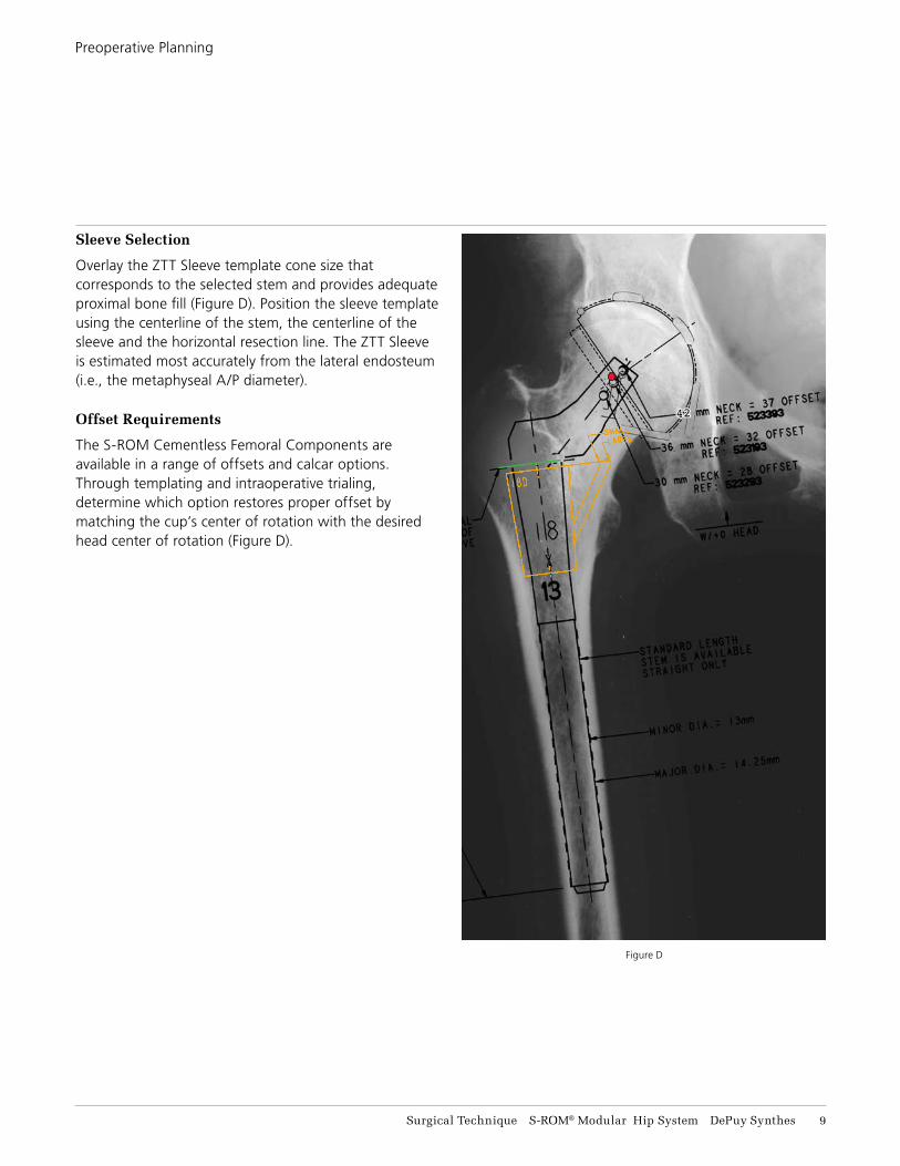
Upon completion of distal reaming, prepare the proximal or “cone” portion of the final sleeve to be implanted. A set of triple banded, color-coded cone reamers are available for preparing the proximal canal (Figure 5). The proximal diameter of each conical reamer is marked in large print. On the opposite side, the three proximal sleeve sizes (i.e., 23mm, 25 mm, & 27 mm) are marked with the corresponding sleeve configuration (i.e., 20 B, 20 D, & 20 F, respectively). The location of each color band moves from distal to proximal as the proximal diameter increases. After attaching the color-coded pilot shaft to the distal end of the conical reamer, advance the reamer until the witness marking of the desired neck length (either 30, 36 or 42 mm) aligns with the tip of the greater trochanter (Figure 6). Consecutively proximally ream until cortical contact is achieved in the proximal femur. Contact will be felt first in the anterior femur in the subtrochanteric region. Do not drive the reamer in reverse.
In the example shown in Figure 5, the final distal diameter revealed that this patient required a 15 mm distal stem corresponding to the blue instrumentation in the MACH1 Instruments. Therefore, the three proximal reamers with blue bands, as well as the blue pilot shafts were selected (Figure 5). Pilot shafts MUST be screwed into the distal end of the proximal reamers before the reamer may be introduced into the femur.
Table 2 shows the stems (proximal reamer diameter at the top and the distal stem diameters at the bottom) and how these stems correlate with the available proximal sleeve sizes.
Caution: You must always place the appropriate size color-coded pilot shaft on the distal end of the proximal reamers.
Figure 5The three proximal reamers available for the 15 mm x 20 mm stem
+3+5
+7
TABLE 2. CONE SIZING CHART (mm)
"Proximal Reamer Diameter"
15 17 17 19 21 23 25 27 29 31
Available Sleeves
14F 16F 18F 20F 22F 24F
12D 14D 16D 18D 20D 22D 24D
12B 14B 16B 18B 20B 22B 24B
"Distal Stem Diameter"
6, 7 6, 7 8, 9 9, 11 9, 11, 13 11, 13, 15 13, 15, 17 15, 17, 19 17, 19, 21 19, 21
11 DePuy Synthes S-ROM® Modular Hip System Surgical Technique
Proximal Ream – Step 2

Figure 6
Cone reaming
Alternative technique
Begin proximal reaming with the smallest of the reamers. In the case of a 15 mm X 20 mm stem, the first proximal reamer used is the 20 B. Note that the first proximal reamer has the color band most distal and is always denoted as B, adding +3 mm to the proximal diameter. If the surgeon feels that more cancellous bone should be removed, a 20 D proximal reamer would be used, adding +5 mm to the proximal diameter. Note that the blue band is now in the middle of the proximal reamer for the D option. Lastly, should the surgeon need to remove even more proximal bone, a 20 F reamer would be selected that would add +7 mm to the proximal diameter. For the F proximal reamer, the color band is most proximal on the reamer.
To summarize, for a 15 mm x 20 mm stem, blue instruments are selected, the final proximal sleeve diameters for B, D and F are 23, 25 and 27 mm respectively.
Alternative Technique: Depending on the osteotomy cut and the ability to visualize the greater trochanter, you may opt to simply line up the top of the proximal reamer with the osteotomy surface as shown by a blue arrow in Figure 6. Trialing would then be critical for selecting the final implants that best restore leg length and femoral offset.
Surgical Technique S-ROM® Modular Hip System DePuy Synthes 13
Proximal Ream – Step 2

Lastly, the spout or triangle of the proximal sleeve must be machined. Spout sizing comes in Small, Large or XX-Large. The spout size on the ZTT Sleeve is proportional to the diameter of the stem.
Use the triangle miller to prepare the femur to accommodate the calcar spout of the final sleeve. In most instances, the final triangle is placed in the medial proximal femur. However, because the placement does not dictate the neck version, the triangle can be rotated 360 degrees to place the sleeve in optimal bone. SPA sleeves (without a spout) are also available in this system to accommodate unusual anatomies. Spout preparation will not be necessary if using a SPA sleeve.
Select the miller shell that has the identical color band pattern as was present on the final cone reamer used in the proximal reaming step (Figure 7). Numeric markings of the proximal diameter are found on cone reamers and miller shells for cross reference verification.
After attaching the miller shell and the miller frame to the appropriate pilot shaft, gently lower the triangle miller. Align the desired neck length witness mark with the tip of the greater trochanter (Figure 7).
The ring of the miller frame can be rotated so that it targets the best available host bone (Figure 8).
Caution: You must always place the appropriate color-coded pilot shaft on the distal end of the triangle miller frame.
Alternative Technique: You can line up the top of the miller frame bevel to the level of the osteotomy surface as shown by the blue arrow in Figure 7 to ensure that the sleeve will fit in the proximal femur. Trialing will be critical for selecting the final implant components that best restore leg length and femoral offset.
Figure 7Positioning of triangle
miller shell
Figure 8Positioning of triangle
miller frame
Alternative technique
14 DePuy Synthes S-ROM® Modular Hip System Surgical Technique
Calcar Ream / Mill – Step 3

Recess to the top of the groove in the triangle miller for the desired spout size as shown by the red arrow in Figure 9. If using a B or D cone, be careful to not allow the triangle milling to go to XXL, since XXL spouts are not available for these cone sizes.
Select the appropriate size miller drill that corresponds to the color-coding used throughout the procedure.
Pass the miller drill through the ring and load the drill tip into the guide hole before starting the drill. Lower the miller frame so that the miller drill makes contact with the cancellous bone to be milled (Figure 9).
Mill on power until desired cortical bone has been exposed. To determine the final spout size (Small, Large, or XXL), make note of the size indicated where the markings on the miller frame align with the top of the miller shell as shown by the red arrow in Figure 9.
Caution: Before proceeding from one spout size to the next, confirm that there is enough calcar bone to accommodate 4 mm of additional reaming to reach the next spout size (i.e., Small to Large or Large to XXL). Please review the Triangle Spout Sizing Chart for more detail.
Small Extends 9.5 mm from the cone
Large Extends 13.5 mm from the cone
XX-Large Extends 17.5 mm from the cone
TRIANGLE SPOUT SIZING CHART
Figure 9Calcar reaming
Surgical Technique S-ROM® Modular Hip System DePuy Synthes 15
Calcar Ream / Mill – Step 3

Trial Sleeve
Secure the sleeve introducer handle (Cat. No. 53-5801) onto the appropriate size sleeve introducer corresponding to the selected sleeve size. As an example, a proximal sleeve trial designated 20 D large is a sleeve that will fit a 15 x 20 stem with a D outer diameter (adding 5 mm to the proximal diameter) and a large spout (extending 13.5 mm). Proximal sleeve trials are color coded. Attach the appropriate colored pilot shaft onto the sleeve introducer and slide on the sleeve.
Note: The trial sleeve is not secured / retained on the sleeve introducer so care must be taken to prevent the trial sleeve from falling off the introducer.
Gently impact the trial sleeve into the prepared metaphysis (Figure 10). Seat the trial sleeve completely and withdraw the introducer handle (Figure 11). At this point, evaluate the sleeve in relation to its final position.
Caution: Make sure that the bolt on the sleeve introducer handle is facing toward the spout. If the bolt cannot be seen, the handle could disconnect from the sleeve introducer attachment.
Figure 10Trial sleeve insertion
Figure 11Trial sleeve position
Bolt must face toward the spout
16 DePuy Synthes S-ROM® Modular Hip System Surgical Technique
Trial

Trial Stem
Restoring patient biomechanics is achieved with a wide range of neck options (Table 3).
Figure 13Trial stem insertion
Figure 14Version adjustment
Each click on trial is 10 degrees
135°
Figure 12
Assemble the trial implant by snapping the chosen neck onto the appropriate size distal stem trial. Align the lateral laser marks in neutral initially and introduce the trial neck and trial stem construct into the femoral canal (Figure 13). The trial neck can be adjusted in 10-degree increments until desired version is obtained (Figure 14). Tighten the trial neck to the trial stem using the nut tightener (Cat. No. 2576-52-100). Trial reduction can also be performed with Long, X-Long and XX-Long distal stem trials.
Figure 12 shows the neck shaft angle and how neck length, lateral offset, and leg length adjustment are measured.
TABLE 3. NECK SIZING CHART — ASSUMES USE OF +0 HEAD
(ALL NECKS HAVE AN INCLUDED ANGLE OF 135 DEGREES)
Neck StyleNeckLength
(mm)Lateral Offset
(mm)
Leg Length Adjustment
(mm)
Standard 30 28 21
Standard 36 32 25
Standard 42 37 30
Standard + 4 Lat 30 32 21
Standard + 6 Lat 36 38 25
Standard + 8 Lat 36 40 25
Standard + 12 Lat 36 44 25
Tip: The opposite end of the nut tightener will thread onto the stem trial for extraction, should that be necessary.
Note: To record version, a Bovie may be utilized on an anatomic landmark.
Surgical Technique S-ROM® Modular Hip System DePuy Synthes 17
Trial

You can separate the trial sleeve and trial stem using the stem-sleeve separator (Cat. No. 53-6450). Remove the trial stem and use the sleeve extractor (not shown), (Cat. No. 2576-00-016) to remove the trial sleeve. The sleeve extractor works by being placed on an extreme angle to catch the distal lip of the sleeve.
Place the proximal sleeve implant onto the sleeve introducer assembly and gently impact the sleeve into the metaphysis (Figure 15).
Again, note that the sleeve is not secured/ retained on the sleeve introducer assembly.
Introduction of the femoral implant into the femoral Canal can be done by hand initially until the distal flutes begin to make cortical contact (Figure 16). A witness mark located on the medial aspect of the femoral implant can be aligned with the corresponding radial laser markings on the superior aspect of the sleeve implant to determine anteversion. Each radial mark on the sleeve represents 20 degrees (Figure 16). Use these orientation lines on the stem and sleeve to ensure that the final implant alignment is consistent with trial alignment.
Figure 15Sleeve insertion
Figure 16Stem insertion
Bolt must face toward the spout
Each line is 20 degrees
18 DePuy Synthes S-ROM® Modular Hip System Surgical Technique
Final Implantation

Figure 17Stem insertion
Place the stem introducer handle (Cat. No. 53-2029) onto the femoral implant and insert the pin punch (Cat. No. 53-1500) into the rotational alignment hole in the femoral neck (Figure 17). Using the pin punch as a version control guide, impact the femoral implant until securely seated. The taper is locked when the stem will no longer advance and 2-3 mm remains between the inferior aspect of the femoral neck and the superior aspect of the implant sleeve.
Confirm the final placement of the S-ROM Implants using the neck resection guide and/or preoperative templates.
Stem Removal Note: It is critical to first unlock the taper between the stem and the sleeve using the stem-sleeve separator (Cat. No. 53-6450). To extract the stem, use the slap hammer instrumentation found in the S-ROM Long Trials & Extraction Instruments case. To assemble the slap hammer, slide the handle (53-1207) into the side of the weight (53-1205), place the weight through the shaft (53-1206). Screw the extractor stem loop (53-4400) onto the end of the slide hammer shaft. Place the extractor stem loop over the head/neck of the stem until the loop engages the trunion/head. Using appropriate force slide the slide hammer weight up impacting the handle stop of the slide hammer shaft until the stem is dislodged.
The S-ROM Sleeve can be placed in 360
degrees of version
Surgical Technique S-ROM® Modular Hip System DePuy Synthes 19
Final Implantation

STEM DIAMETER & LENGTHS
FEMORAL NECKS STANDARD
FEMORAL NECKS LATERALIZED
FEMORAL NECKS CALCAR REPLACEMENT
& LATERALIZED
Neck Length 30 36 42 30 +4 36 +6 36 +8 36 +12 36 +21 36 +21 +4
36 +21 +8
Lateral Offset w/ +0 Femoral Head
28 32 37 32 38 40 44 32 36 40
Leg Adjustment Length 21 25 30 21 25 25 25 46 46 46
12
x6
N Standard 115mm 523206
12
x7
N Standard 115mm 523207
14
x8
N Standard 130mm 523208
14
x9
N Standard
130mm 523291 150mm 523251
130mm 523191
130mm 563514
N,L,R Long
205mm 526514N 526514L 526514R
205mm 563214N 563214L 563214R
205mm 526614N
16
x11
N Standard 150mm 523292
150mm 523192
150mm 563516
150mm 563517
150mm 526676
N,L,R Long
205mm 526516N 526516L 526516R
205mm 563216N 563216L 563216R
205mm 563016N 563016L 563016R
N,L,R X-Long
240mm 563036N 563036L 563036R
N,L,R XX-Long
300mm 563056N 563056L 563056R
18
x13
N Standard 160mm 523293
160mm 523193
160mm 523393
160mm 563518
160mm 523418
160mm 563618
160mm 526678
N,L,R Long
215mm 526518N 526518L 526518R
215mm 526418N 526418L 526418R
215mm 563118N 563118L 563118R
215mm 563018N 563018L 563018R
N,L,R X-Long255mm 563138L 563138R
255mm 563038N 563038L 563038R
N,L,R XX-Long315mm 563158L 563158R
315mm 563058N 563058L 563058R
20
x15
N Standard 165mm 523194
165mm 523394
165mm 523420
165mm 563620
165mm 526680
N,L,R Long
225mm 526520N 526520L 526520R
225mm 526420N 526420L 526420R
225mm 563120N 563120L 563120R
225mm 563020N 563020L 563020R
N,L,R X-Long270mm 563140L 563140R
270mm 563040N 563040L 563040R
N,L,R XX-Long325mm 563160L 563160R
325mm 563060N 563060L 563060R
11 DePuy Synthes S-ROM® Modular Hip System Surgical Technique
Implant Ordering Information

STEM DIAMETER & LENGTHS
FEMORAL NECKS STANDARD
FEMORAL NECKS LATERALIZED
FEMORAL NECKS CALCAR REPLACEMENT
& LATERALIZED
Neck Length 30 36 42 30 +4 36 +6 36 +8 36 +12 36 +21 36 +21 +4
36 +21 +8
Lateral Offset w/ +0 Femoral Head
28 32 37 32 38 40 44 32 36 40
Leg Adjustment Length 21 25 30 21 25 25 25 46 46 46
22
x17
N Standard165mm 523195
165mm 523395
165mm 523422
165mm 563622
165mm 526682
N,L,R Long
230mm 526522N 526522L 526522R
230mm 526422N 526422L 526422R
230mm 563122N 563122L 563122R
230mm 563022N 563022L 563022R
N,L,R X-Long275mm 563142L 563142R
275mm 563042N 563042L 563042R
N,L,R XX-Long325mm 563162L 563162R
325mm 563062N 563062L 563062R
24
x19
N Standard175mm 523196
175mm 523396
175mm 523424
175mm 563624
175mm 526684
N,L,R Long
230mm 526424N 526424L 526424R
230mm 563124N 563124L 563124R
230mm 563024N 563024L 563024R
N,L,R X-Long275mm 563144L 563144R
26
x21
N Standard175mm 523197
175mm 563626
Size Small LargeXX
Large SPA
12B 550570 550571
12D 550572 550573
14B 550501 550502 535342
14D 550503 550504 535344
14F 550505 550506
16B 521463 521465 535362
16D 550513 550514 535364
16F 550515 550516 550520 535366
18F Oversized 550717 550718 550721
Size Small LargeXX
Large SPA
18B 521483 521485 535382
18D 550523 550524 535384
18F 550525 550526 550530 535386
20F Oversized 550727 550728 550731
20B 521403 521405
20D 550533 550534
20F 550535 550536 550540
22F Oversized 550737 550738 550741
Size Small LargeXX
Large SPA
22B 521423 521425
22D 550543 550544
22F 550545 550546 550550
24F Oversized 550747 550748 550751
24B 550561 550562
24D 550564 550565
24F 550567 550568 550569
24D Undersized 550770 550771 550772
24F Undersized 550777 550778 550779
PROXIMAL SLEEVES ZTT™ / ZTT™ SPA
Surgical Technique S-ROM® Modular Hip System DePuy Synthes 11
Implant Ordering Information
*The S-ROM Stems have a 135 Degree Neck Angle

Important
This Essential Product Information sheet does not include all of the information necessary for selection and use of a device. Please see full labeling for all necessary information.
Indications
Total Hip Arthroplasty (THA) is intended to provide increased patient mobility and reduce pain by replacing the damaged hip joint articulation in patients where there is evidence of sufficient sound bone to seat and support the components. The components of the S-ROM Total Hip System are indicated for use in total hip replacement procedures for patients suffering severe pain and disability due to structural damage in the hip joint from rheumatoid arthritis, osteoarthritis, post-traumatic arthritis, collagen disorders, avascular necrosis, and nonunion of femoral fractures. Use of the prosthesis is also indicated for revision of previous hip arthroplasty and for patients with congenital hip dysplasia, protrusio acetabuli, slipped capital femoral epiphysis, and disability due to previous fusion. The ZTT Porous Coated Proximal Sleeves and SPA Porous Coated Proximal Sleeves are indicated for cementless application only.
Contraindications
Use is contraindicated in cases with active or recent joint sepsis, insufficient bone stock, marked atrophy or deformity in the upper femur, skeletal immaturity, or where loss of musculature or neuromuscular disease would render the procedure unjustifiable.
Warnings and Precautions
S-ROM femoral heads with +12 neck length extension cannot be used with the POLY-DIAL™ constrained liner. Any S-ROM ceramic femoral head that has been impacted or dropped should be discarded and another ceramic femoral head used. If a ceramic femoral head is removed from the femoral stem after assembly, a new head should be used. The removed head should be discarded and under no circumstances be reused. Do not use ceramic heads with constrained acetabular liners. The femoral head size and the inner diameter of the acetabular components must correspond. ZT and ZTT oversized proximal sleeves must be used with S-ROM stems having a nominal proximal diameter 2 mm smaller than the nominal diameter of the sleeve. For all other S-ROM proximal sleeves, the nominal proximal stem diameter must correspond with the nominal diameter of the sleeve. The trochanter screws and washers must be used together with the S-ROM 36+21 calcar replacement neck femoral stem.
Adverse Events
Peripheral neuropathy, deep wound infection, and heterotopic bone formation have been reported following hip replacements. Subclinical nerve damage has also been reported. Dislocation, subluxation, muscle and fibrous tissue laxity, and loosening may also occur.
The ceramic femoral heads are composed of new ceramic materials with limited clinical histories. Because of the limited clinical and preclinical experience, the long-term biological effects of these particulates are unknown. Histological reactions have been reported as an apparent response to exposure to a foreign material.
11 DePuy Synthes S-ROM® Modular Hip System Surgical Technique
Essential Product Information


DePuy Orthopaedics, Inc.700 Orthopaedic DriveWarsaw, IN 46582USATel: +1 (800) 366-8143Fax: +1 (800) 669-2530
www.depuysynthes.com
Limited Warranty and Disclaimer: DePuy Synthes products are sold with a limited warranty to the original purchaser against defects in workmanship and materials. Any other express or implied warranties, including warranties of merchantability or fitness, are hereby disclaimed.
Please also refer to the package insert(s) or other labeling associated with the devices identified in this surgical technique for additional information.
CAUTION: Federal Law restricts these devices to sale by or on the order of a physician.
Some devices listed in this surgical technique may not have been licensed in accordance with Canadian law and may not be for sale in Canada. Please contact your sales consultant for items approved for sale in Canada.
Not all products may currently be available in all markets.
© DePuy Synthes 2018. All rights reserved. 103479763 Rev 1