Embed Size (px)
Citation preview

RAILTECH INTERNATIONAL, SA au capital de 15 851 323 €uros – Siège Social : Z.I. du Bas Pré – B.P. 9 – 59500 RAISMES - FRANCE
Tél +33(0)3 27 22 26 26 – Fax +33(0)3 27 22 26 00 - www.railtech.fr
RCS Valenciennes 389 670 142 – Siret 389 670 142 00030 – Ident. TVA FR 00 389 670 142
Etablissement de RAISMES
Z I du Bas Pré
BP 9
59500 RAISMES
FRANCE
Tél +33(0)3 27 22 26 26
Fax +33(0)3 27 22 26 00
Email : [email protected]
Siret 389 670 142 00030
PP RR OO CC EE SS SS
FF OO RR
AA LL UU MM II NN OO TT HH EE RR MM II CC WW EE LL DD II NN GG
S R G
41 GP - UK
O N E S H O T C R U C I B L E
REVISION N°0.5 (14/11/2013) Décembre 2012
REF MAN /SRG/25/LU-JS/OP/CJ/12-2012/SB N° C 40 20 5 EN
G A P
L U T I N G
P R E H E A T I N G
O N E - S H O T - C R U CI B L E

2 | P a g e
CONTENTS
PART I - GENERAL OPERATING INSTRUCTIONS
PART II - PRELIMINARY WORKS
PART III - APPLICATION - WELDING EXECUTION
PARTIE I - GENERAL OPERATING INSTRUCTIONS
I/ 1 - GENERAL REMARKS 6
I/ 1.1 - Quality 6
I/ 1.2 - Before leaving for the site 7
I/ 1.3 - Safety 8
I/ 2 - CHECK OF THE JOINT TO BE WELDED 9
I/ 3 - IDENTIFICATION 10
I/ 3.1 - Consumables 10
I/ 3.1.1 - Sand moulds kit 11 I/ 3.1.2 - Felt moulds kit 11 I/ 3.2 - Kit marking 12
I/ 3.3 - Portion marking 13
I/ 3.4 - Mould marking 13
PARTIE II - PRELIMINARY WORKS
II/ 1 - ONE-SHOT CRUCIBLE 15
II/ 2 - ADJUSTING THE SHEARING TOOLS 16
II/ 3 - VERIFICATION OF PREHEATING MATERIAL 17
II/ 3.1 - Oxy-propane preheating 18 II/ 3.2 - Safety measures before preheating set starting 18

3 | P a g e
PARTIE III - APPLICATION - WELDING EXECUTION
PREPARATION OF THE JOINT TO BE WELDED 20
III/ 1 - ADJUSTING THE JOINT 21 III/ 1.1 - Welding gap 21 III/ 1.2 - Vertical alignment (PEAK) 21 III/ 1.3 - Twisting of the rails 22 III/ 1.4 - Horizontal alignment 22 III/ 1.5 - Gap checking 22
III/ 2 - MOULDS SETTING 23
III/ 2.1 - Groove core setting 23 III/ 2.2 - First half mould setting 23 III/ 2.3 - Second half mould setting 24 III/ 2.4 - Setting the briquet 24 III/ 2.4.1 - Sand briquet 25 III/ 2.4.2 - Felt briquet 25
III/ 3 - LUTING 27
III/3.1 - Sand moulds 27 III/3.2 - Felts moulds 27
III/ 4 - PREHEATING 28
III/ 4.1 - Oxy-propane preheating 32
III/ 5 - ONE SHOT CRUCIBLE LOADING 34
III/ 6 - POURING 35 III/ 6.1 - As soon as the preheating is over 35 III/ 6.2 - Reaction 35
III/ 7 - WITHDRAWING THE SLAG TRAY 37
III/ 8 - UNMOULDING 37
III/ 9 - SHEARING 38
III/ 10 - REMOVING RISERS 38
III/ 11 - ROUGH GRINDING 39
III/ 12 - FINAL WELDING 40
III/ 12.1 - Final grinding 40 III/ 12.2 - Cleaning 40 III/ 12.3 - Verification 40 III/ 12.4 - Marking and tracking 40
APPENDICES 41
Appendices 1-A-B-C Welding Tools 42 Appendices 2-A-B-C Preheating tools 45 Appendices 3 Check list for a welding team 49 Appendices 4 Line of preheating 54

4 | P a g e
FOREWORD
This manual concerns instructions for successfully carrying out the welding:
SRG Oxy Propane with ONE SHOT CRUCIBLE
The SRG process is used with two kinds of gap:
Normal gap 25mm
Respect the general instructions and apply the specific requirements in
accordance with your worksite and rail profile.
The SRG process could be used with
Sand moulds
Felt moulds
The SRG process could be ignited with two systems:
Ignitor
STARTWEL® ignition system
THIS DOCUMENT DOES NOT REPLACE THE RAILWAYS SPECIFICATIONS AND SAFETY
INSTRUCTIONS CONCERNING EXECUTION OF WELDING OPERATIONS AND RECEPTION OF
WORKS DETERMINED BY THE CUSTOMERS

5 | P a g e
PART I
GENERAL OPERATING INSTRUCTIONS

6 | P a g e
I/ 1 - GENERAL REMARKS
I/ 1.1 - QUALITY Quality is achieved when all precautionary measures are required at each step of the works in progress, CHECK:
The gap value, the tolerance span limits
Joint inspection
Rail adjustment
Moulds inspection
Moulds and briquet centring
Luting
Burner positioning
Preheating time
Preheating pressures
Portion bag
Crucible inspection
Crucible centering
Tapping time
Unmoulding time before shearing
Adjusting shear blades
Cooling time
Final grinding
It is recommended to carry out the welding at a temperature over > 0°C. If the temperature is under this limit we get gas characteristics (flow/pressure) inappropriate
to achieve the expected quality level.
In any case: All consumables (crucible, moulds ...) and hardware
as well as the work site should be carefully protected from the rain.

7 | P a g e
I/ 1.2 - BEFORE LEAVING FOR THE SITE
Make sure that the operator disposes of the equipment necessary for the performance of the works and more particularly:
Enough kits to perform all the welds and check if the kits are appropriate to the profiles to weld and to the types of welds (See § I/ 3 - Identification)
For Oxy-propane :
Check the condition of the preheating equipment and if there are enough consumables, connection, flexible joints, hoses, manometer, pressure reducers in perfect condition…
Complete set of hardware (base plate, jackets, mould clamp) (See Appendix 1 - Welding hardware)
Control tools: straight edge, wedges, chronometer, gauge...
Procedure or welding draft in force on the network
The necessary equipment to prepare and to finish the welds : A frame aligners, grinding machine, and the necessary expendable (oil, petrol, grinding disks, ...)
The tools necessary to perform small reparation concerning hoses, etc...
Safety equipment (goggles, gloves ...), safety signs and so on...

8 | P a g e
I/ 1.3 - SAFETY
Welding includes all the usual risks to be found in on-site work.
The personal safety equipment must be wear at any time during welding operations.
Fireproof industrial clothing
Leather gloves
Fireproof gloves
Safety shoes
Leggings
Safety goggles with side protections again sparks (plain glasses)
Welder's goggles (protection glasses)
Consult the safety regulations in force in your network

9 | P a g e
I/ 2 - CHECK OF THE JOINT TO BE WELDED
Clean (remove the grease) and brush rail ends in order to
eliminate all traces of oxidation («rust»). A poorly cleaned rust deposit can cause some porosities into the weld.
Check the geometrical aspect of the two rails ends.
Check if there is no crack (cut again the rail with cutting machine if necessary).
Check if there is no steel smudge which can affect the correct positioning of the moulds (grinding if necessary)
The gap shall be:
23 mm to 27 mm for SRG 25 (25 +/- 2 mm)
In order to obtain this gap, it may be necessary to cut the rails. In this case use only a rail saw or a disc cutting machine.
Strictly follow the safety instructions (notice) concerning the use of your saw.
It is forbidden to weld directly on rail ends cut by oxy propane cutting flame. If necessary, take care to clean them up carefully by taking off the slag from the rail ends.
The out of square ness of the rail ends must not exceed 1,5mm. To obtain the right value, use equipment which is in good aspect, correctly fixed to the rail.
CAUTION
The cut shall be carefully cleaned to remove all traces of grease and oxidation to avoid having any defects.

10 | P a g e
I/ 3 - IDENTIFICATION
I/ 3.1 - CONSUMABLES
In order to avoid any lack of the products necessary for the welding operation on site all products are put into a same package which is called kit. To avoid having humidity into the product, a plastic wrapped protection is put around the kit.
Opening the kit: it is important to check if the original packaging has been preserved, if it is correctly closed and shows neither deformation nor moisture spots.
Only use the portion supplied into one kit. Never mix the components of 2 different kits available for others grades or profiles. Never use an open or defective bag. Do not add anything else. Never mix 2 welding portions
II
MM
PP
OO
RR
TT
AA
NN
TT

11 | P a g e
I/ 3.1.1 - SAND MOULD KIT
The kit consists of:
2 half moulds
1 briquet
1 plug
1 groove core
1 portion bag (plastic) watertight
I/ 3.1.2 - FELT MOULD KIT
The kit consists of:
2 half felt moulds
1 felt briquet
1 plug
1 groove core
1 portion bag (plastic) watertight

12 | P a g e
I/ 3.2 - KIT MARKING
Kit identification has the following indications on the box
- on one side the tracing of the product
and on the other side the identification of the product : profile, process…
SAND MOULDS
FELT MOULDS
Profile Moulds Process Profile Moulds Process
41GP SRG 41GP JS SRG
Portion Process Gap Grade Charge Process Gap Grade
D44 SRG CJ 25 G D44 SRG CJ 25 G
Batch Batch
2D4160 2D4160
Preparation date Article code
5 October 2012 XXXXXXXX

13 | P a g e
I/ 3.3 - PORTION MARKING
The references indicated on the snap set adhesive label shall be kept for tracing of the weld.
I/ 3.4 - MOULDS MARKING
The printing of the mould packaging includes the following informations :
SAND MOULDS
FELT MOULDS
Profile Moulds Profile Moulds
41GP 41GP JS
Process Gap Process Gap
SRG 25 SRG 25
Date Preparator Date Preparator
05.09.11 81 05.09.11 81
Article code Article code
XXXXXXXX XXXXXXXX
Article code /
X X X X X X X X X /
Preparation date / Batch
5 Septembre 2012 / 2D4160

14 | P a g e
PART I I
PRELIMINARY WORKS
The different stage developed in this part are essential and must be realised with harshness to obtain in a hand a good quality, and in an other hand
security for the workers.

15 | P a g e
II/ 1 - ONE SHOT CRUCIBLE
The one-shot crucible is made from a refractory compound by means of a resin. It can be used as such and does not require any preparation. The fusible component allowing the automatic tapping is placed during fabrication.
However to keep good safety conditions and quality it is absolutely necessary to check:
The original packing
The crucible is not damaged or wet
The crucible should be stored in standing position in a dry place and free of moisture
The automatic tapping is not damaged
Safety :
In the exhaust of non tapping The melting steel flows through the safety valve. The crucible is then pulled out with the special fork. NEVER REMOVE THE CRUCIBLE MANUALLY.
In the exhaust of non tapping of the safety valve or crucible
Leave the crucible in its position until self-destruction

16 | P a g e
II/ 2 - ADJUSTING THE SHEARING TOOLS
For each rail profile, one shearing blade is dedicated
Adjustment of blades:
To increase the shearing, the adjustment of the blades must be done systematically after sharpening or the changing of the blades themselves.
Allow a gap of 1,5 mm minimum between the blades and the laterals faces of the head.
The weld shear blades must de adjusted to leave 1,5 to 2mm of weld metal above the running surface for profile grinding.
Adjustment of screws:
To avoid damaging the blades, the shear blades must de adjusted to leave 1mm between them by adjustment of the screws dedicated.
Sleeper Sleepers Adjustable stop

17 | P a g e
II/ 3 VERIFICATION OF PREHEATING MATERIAL
The material is presented in appendix 3 (Cf preheating)
II/ 3.1 - OXY-PROPANE PREHEATING
The preheating is fed with a blowpipe, equipped with propane and oxygen hoses by two pipes which are 10 mm in diameter for the oxygen and 8mm in diameter for the propane and 20 m long under pressure.
II/ 3.2 - SAFETY MEASURES BEFORE PREHEATING SET STARTING
Check gas cylinder are full enough to ensure a full duration of the preheating procedure,
Check the blowpipe is in good general condition,
Check the regulator to obtain a good flame. The darting flame shall be maintained around 25 mm,
Check the hoses,
Check cylinders are in correct vertical position.

18 | P a g e
PART I I I
WELDING PERFORMANCE

19 | P a g e
PREPARATION OF THE JOINT TO BE WELDED
Dismount the fastenings on 3 sleepers on each side of the joint to be welded ( and more in a curve depending on its radius)
Clean and brush the ends of the rail in order to eliminate all traces of grease or oxidation.
Check the dimensional quality of the ends to be welded (Cf § I/2)
> 6 IN CURVE > 3 IN ALIGNMEN
>6
>3 >6
>3

20 | P a g e
III/ 1 - ADJUSTING THE JOINT
This adjustment is especially important because
it determines the geometric quality of the welding and insure its lifespan
III/ 1.1 - WELDING GAP
This is the distance between the two rails ends.
25 +/- 2 mm for SRG 25mm
This space is measured with a graduate gauge on both sides of the rail, at the rail head and base, that is to say at 4 different places.
The limit values of the four measurements taken must fall within the tolerance span determined above.
The limit values of the four measurements taken must fall within the tolerance span determinated above
III/ 1.2 - VERTICAL ALIGNMENT (PEAK)
The rails shall show a peak before welding. This peak is absolutely necessary because it equalizes metal shrinking after cooling. The value of the peak must be adjusted by the welder, depending on the track.
The importance of the slope shall be measured after finishing grinding. The railway company shall indicate the final angle.
The rails shall never show hollows
Measurements approximately 50 mm from the ends of the straight edg

21 | P a g e
III/ 1.3 - TWISTING OF THE RAILS
Inclination of the rails must be carefully checked
- The inside surface of the railhead (1)
- The base and web of the rail (2)
III/ 1.4 - HORIZONTAL ALIGNMENT
Check the inside face of the rail
Recommandation In general, during operation of adjustment it advices to use A frame aligners.
III/ 1.5 - GAP CHECKING
Check if the gap is still into the tolerances
The gap must remain in the values of 25 +/- 2 mm or 48 +/- 3 mm.

22 | P a g e
III/ 2 - MOULDS SETTING
III/ 2.1 - GROOVE CORE SETTING
Position the clamp assembly in relation to the gap axis.
Apply luting paste in the groove to avoid that the core moves.
III/ 2.2 - FIRST HALF MOULD SETTING
Position the clamp assembly in relation to the gap axis
Place each half mould on respective mould shoe. The levers are placed toward the inside in open position.
The correct position of the lateral side plate on the mould is visible by the orifice on each side plate.
Fit the first half mould centrally to the welding gap axis.
Maintain this half mould in position and tight the screw of the clamp assembly.
Orifice of visualisation

23 | P a g e
III/ 2.3 - SECOND HALF MOULDS SETTING
Place the second half mould centrally to the gap.
Loosen slightly the screw of the clamp. (without breaking the moulds by over tightening).
Adjust the moulds if they are not correct centre into the gap.
Tighten the clamp sufficiently
Check that no sand has entered into the moulds.
III/ 2.4 - SETTING THE BRIQUET
Check with the briquet the vertical angle of both rails.
Place the briquet in its base plate. Make sure that it suits in the plate correctly (no wobbling)
CAUTION When the rails present a difference of wear, check the perpendicularity of moulds to rail:
- Loosen slightly the screw of the clamp - Centre moulds into the gap axis. - Tighten the clamp sufficiently

24 | P a g e
III/ 2.4.1 - SAND BRIQUET
Luting paste shall be applied into the two recesses on either side of the briquette.
Cut the paste in excess. The upper surface of the paste layer shall exceed the upper surface of the briquette.
Place the bottom plate set under the rail and centre it in relation to gap and rail.
III/ 2.4.2 - FELT BRIQUET
Preparing the tube of paste
Cut the cartridge tip, screw the nozzle on,
Cut the tip in such a way as to obtain approximately a 20 mm outlet,
Fit the distributor with the cartridge.
Apply a strip of luting paste first of all in the two recesses on
either side of the refractory felt, (Pict. A), and secondly on the width of the base plate (both sides) (Pict B).
Take care not apply paste on the felt.
(pict. a)
Put the base plate under the moulds.
(pict. b)

25 | P a g e
Attache the fasteners to either side and check the centring of the plate in relation to the moulds,
Handle with each hand the two handfuls.
Turn both hands at the same time.
It is recommended to cover the moulds with cardboard when these operations have been done.
After briquette setting, tap the bottom plate set and making of correct support
Moulds and briquet have auto-centering system. During setting briquet with the two locking handles, visualise the correct position of the base plate and briquette.

26 | P a g e
III/ 3 - LUTING
III/ 3.1 - SAND MOULDS
Apply a strip of luting paste into all recesses around the perimeter of the rail, moulds joints, including the bottom of the base.
Level carefully the paste exceeding the higher lever of the bottom briquet.
III/ 3.2 - FELT MOULDS
Apply a continuous paste trip into all recesses around the perimeter of the rail and mould joints.
Apply additional paste to the vertical mould joint above the rail head.
Place the slag tray and seal the parting line between the slag tray and the moulds.

27 | P a g e
III/ 4- PREHEATING
The SRG process is used with one kind of preheating:
Oxy-propane preheating (§ III/4.3)
The preheating consist in heating at characteristic process temperature the ends of the rail
during a limited time.
The good execution of preheating is essential for the life span of the weld. It is thus compulsory to respect carefully the specification described below.
Preheating is an operation of major importance. Its function lies in the elimination of residual
humidity from the moulds and to raise the temperature of the rail ends to a determined value
characterised by the process.

28 | P a g e
II/ 4.1 - OXY - PROPANE PREHEATING
RAILTECH materials recommended
(Conf Appendices 2B)
III/ 4.1.1 - BLOWPIPE FITTING
To obtain a correct preheating:
Fit the blow pipe in its support and centre the nozzle in the middle of the moulds.
The distance between the end of the nozzle and the rail top is to 50 mm. (d)
Remove the blowpipe from its support.
III/ 4.1.2 - LIGHTING THE BLOWPIPE
At first, open the oxygen tap and then propane tap,
Adjust progressively the gas flow until taps are completely open. The manometer of propane and oxygen cylinders must indicate respectively 0,6 bar and 1,2 bar.
The cone length must measure around 25 mm.
d
WARNING ! Propane and oxygen pressures must be maintained throughout the duration of the
preheating.(see appendix 2-C) The cone length must measure around 25 mm.
If it is not the case, adjust the propane pressure.
Caution: Low temperature

29 | P a g e
After the blowpipe lighting gas exhaust shall be regular and symmetric at the both side pipe in order to get 40cm flames at the exhaust.
Place the plug by the exhaust with the upper side against the flame. (Take care not block the exhaust)
III/ 4.1.3 - PREHEATING TIME
After having adjusted the flame, the burner has to preheat during 4 minutes for the gap 25mm.
During this time, prepare the crucible (see§ III/ 5 )
III/ 4.1.4 - BLOWPIPE REMOVING Once the preheating is completed, respect strictly the safety instruction.
Remove the blowpipe and take care not to damage the inside of the moulds,
First turn the propane feed off and then the oxygen feed.
If there is backfire (whistling), Turn off propane feeding at once.

30 | P a g e
III/ 5 - ONE SHOT CRUCIBLE LOADING
Open the bag and pour the portion into the one-shot crucible
Place the crucible by the working area and place the ignitor or the starter STARTWEL® in the portion ready to use,
CAUTION : For STARTWEL® application, the portion must always be horizontal in the crucible.
NO YES
Place the CJ fork and the shovel waste
Caution ! It is important that only use the welding portion delivered with the kit. Never mix the contents of two different kits (never use moulds from one kit, the welding portion from another, the thimble from a third, etc…). Never use a welding portion bag which is gutted or incomplete. Do not add anything. Never mix two welding charges. Never use a damaged or cracked crucible
Always use the fork provided for this purpose (Never manually)
IMPORTANT

31 | P a g e
III/ 6 - POURING
Welding in wet weather: All consumables must be kept dry and wet rails dried for welding
III/ 6.1 - AS SOON AS THE PREHEATING IS OVER
Put the plug into its lodging with the pliers provided for this purpose and slightly drive it
III/ 6.2 – REACTION In the case of ignition with the ignitor: Light the ignitor by contact with inside hot mould
wall.
Don't dip the ignitor too much, only stitch it into the portion (3 cm). Tapping time could be affected and should be under the minimum value i.e. 17 seconds.
In the case of ignition with STARTWEL®:
Remove the pin from the starter.
Insert the starter in the hole in the cap (In case of filter cover, remove the lid first, take care not to put sand in the portion)
(Filter cover)

32 | P a g e
Centre the crucible lead
The reaction develops in a few seconds and the
pouring will automatically take place at reaction completion (if no tapping see II/1).
The tapping time should be between 17 to 32
seconds.
Position the ignition glue indicator in front of you.
Place the electrodes of the electric handle on
the terminals of the STARTWEL® starter.
Press and hold the trigger until ignition (charge has started when the red light becomes visible)
The reaction occurs in a few seconds and the casting is carried out automatically after the end of the reaction
The tapping time should be between 17 to 32 seconds.
After the casting, removed the crucible with the fork.

33 | P a g e
III/ 7 - WITHDRAWING THE SLAG TRAY
Break the solidified slag between the moulds and the slag tray.
Breaking the solidified slag tray will prevent breaking into the moulds too early.
III/ 8 - UNMOULDING
It is absolutely necessary to remove the mould before shearing
Before removing the jackets wait:
Start the unmoulding at around:
Shear the upper part of the moulds with the hot cut chisel and check if the steel is not still liquid.
GAP 25MM
3 minutes After the
pouring 5 minutes
Caution! The slag tray must be removed only after its content has fully solidified. Place the slag tray with hot content on a dry spot (not on sleepers). Do not place or throw slag tray with hot content on wet surface or into water
Caution! Do not unmould if the steel is still liquid.

34 | P a g e
III/ 9 - SHEARING
Start the shearing at:
Mould sand and loose paste must be cleaned from the rail head each side of the weld, by wire brushing.
Begin the shearing operation by running surface, rail head and risers.
III/ 10 - REMOVING RISERS
There are two operating ways to remove the risers:
Use an electric disk equipped with a disk allowing cold or hot shearing of the risers
or
Begin with hot notching. This operation shall be performed quickly after shearing, if not metal is too hard. After notching break the risers.
GAP 25MM
6 minutes After the
pouring

35 | P a g e
III/ 11 - ROUGH GRINDING
Rough grinding of the rail head portion of the welding can be performed after shearing or hot cutting is completed
Rough grinding of the running surface of the rail shall be performed with an approved surface grinding wheel.
Let an excess metal thickness on the running surface according to the customers requirements.
III/ 12 - WAITING TIME BEFORE RUNNING
The utilisation of weld corresponds at passage of circulation, train of works, so traction of the weld with hydraulic stretcher (traction with the stretcher, carrying of stretcher…)
The utilisation of weld is possible:
That is correspond at the temperature of 350°C
Wait about 15 minutes after the casting to remove tools using for the rails adjustment.
GAP 25 MM After the casting
25 minutes

36 | P a g e
III/ 13 - FINAL WELDING
III/ 13.1 - FINAL GRINDING
The target of the final grinding is to establish a perfect continuity between the two rails which were welded.
The final grinding is realised according to the customers requirements.
The final grinding should be done on a cold rail and totally stabilised.
III/ 13.2 - CLEANING
Remove all the sand, paste…left around the weld.
Remove all burrs with a grinding wheel
Grind the excess of steel (base of the risers) according to the customer requirements. (According to the customer requirement)
III/ 13.3 - VERIFICATION (According to the customer requirement)
III/ 13.4 - MARKING AND TRACKING (According to the customer requirement)

37 | P a g e
A P P E N D I C E S Appendix 1 / A - B - C - D WELDING TOOLS Appendix 2 / A - B - C - D PREHEATING TOOLS Appendix 3 INCORRECT PRESSURES Appendix 4 CHECK LIST FOR A WELDING TEAM Appendix 5 PREHEATING LINE RAILTECH

38 | P a g e
APPENDIX 1 – A – Welding Tools
BOTTOM PLATE The bottom plate is the same for gap 25 or 48mm.
BOTTOM PLATE 83100004
SIDE PLATE The side plate is the same for gap 25 or 48mm.
SET OF SIDE PLATES 83200001
SLAG TRAY
SLAG TRAY 81532010
PLUG TOOLS This tool allows the insertion of the plug after the preheating.
PLUG TOOL 83432920
GAUGE This gauge allows control of the gap.
GAUGE S0000150

39 | P a g e
APPENDIX 1 – B – Welding Tools / For One Shot Crucible
ONE SHOT CRUCIBLE
CJ1G1 83450127 CJ1G1 CCF* 83450129
*CCF: One Shot Crucible with filter cover
CLAMP ASSEMBLY ONE SHOT CRUCIBLE FOR RAG
This moulds clamp is equipped with a U clamping for fixing to the rail.
CLAMP ASSEMBLY 832500004
FORK
The fork allows the removal of the CJ after casting.
FORK CJ 82631411

40 | P a g e
APPENDIX 1 – C – Welding Tools / Ignition Tools
IGNITOR
IGNITOR BOX (x100) 82632450
STARTERS STARTWEL®
BOX OF 10 STARTERS STARTWEL® 82632501
BOX OF 100 STARTERS STARTWEL® 82632502
ELECTRIC HANDLE COMPLETE 82632503
ELECTRIC HANDLE ONLY 82632509
BATTERY 14,4V 82632503

41 | P a g e
APPENDIX 1 – C – Welding Tools / Ignition Tools
CHARGER
CHARGER 220V FR 82632505
EMPTY METAL CASE
EMPTY METAL CASE 82632506
VALISE COMPLETE The complete case includes:
A handle (1) 14.4 V battery with a lithium-ion (2) A battery charger (4)
1 box of 10 starters STARTWEL® (3)
COMPLETE CASE 82632507
CASE WITHOUT CHARGER The bag includes: A handle with a 14.4 V battery Li-Ion
1 box of 10 starters thermal STARTWEL®
CASE WITHOUT CHARGER 82632508

42 | P a g e
APPENDIX 1 – D – Welding Tools / Luting Tools
LUTING WITH PASTE CAULKING DISTRIBUTOR – FELTS MOULDS
PASTE CAULKING DISTRIBUTOR
PASTE CAULKING DISTRIBUTOR 83461109 PASTE CAULKING DISTRIBUTOR COMPENSATION 83461110
LUTING PASTE
PASTE CARTBRIDGE(unity) 83661130 PASTE CARTBRIDGE (Box of 12) 83661111
MANUAL LUTING – SAND MOULDS
LUTING PASTE
LUTING PASTE BUCKET (10Kg) 83661130
WORN RAIL – SAND MOULDS
FELT SEAL
FELT SEAL BOX (x30) 83661115

43 | P a g e
APPENDIX 2 – C – Preheating Tools / Oxy-Propane preheating
BLOWPIPE
BLOWPIPE 22HOLES 35910229
BLOWPIPE SUPPORT
BLOWPIPE SUPPORT FOR RAG 11234004
GAS LIGHTER
GAS LIGHTER 48402002
For the others elements, see appendix 4 – PREHEATING LINE RAILTECH

44 | P a g e
APPENDIX 3 – Incorrect pressures
IN CASE OF INCORRECT PRESSURES
The pressures must be maintained throughout the duration of the oxy – propane preheating.
The manometers must be adjusting to: 0,6 bar for the propane 1,2 bar for the oxygen
The cone length must be always around 25 mm. If it is not the case, adjust the propane pressure at the regulator.
It’s very important to check the pressure of propane and oxygen throughout the duration of the preheating. In the other cases, two solutions can be considered according to requirement of building site:
The welder carries out the welding until his term and declares this welding as defective.
The welder has to restart again his weld since the beginning (checking of the gap, setting new moulds…)

45 | P a g e
APPENDIX 4 – Check list for a welding team
HAND TOOLS TYPE QUANTITY RÉFÉRENCES
WIRE BRUSH 1 48401004
ELECTRONIC TIMER 1 48703001
PLUG HOLDER 1 83432920
HOT CUT CHISEL 5 KG 1 48401110
BALLAST FORK 1 48401050
ADJUSTABLE PLIERS 0 TO 46 1 48401131
ADJUSTABLE SPANNER 0 TO 30 1 48401010
SET OF SCREWDRIVERS 1 48401015
SET OF 5 FLAT SPANNERS 1 48401130
TOOLS BOX 1 48401008
HAND HAMMER 1 48401013
HAMMER 1 48401013
HOT CUT CHISEL WITH HANDLE 1 11311001
TRANCHE À ÉVENT DE PATIN AVEC MANCHE 1 11311002
COLD CHISEL 1 48401009
BALLAST FORK 1 48401050
SET OF NUMBER-PUNCH 1 48409002
SET OF LETTER-PUNCH 1 48409003
SET OF THICKNESS GAUGES 1 48701005
COPPER HAMMER 1 11319002
REFUSE TRAY 1 48401014
METAL JERRYCAN 20LITRES 2 48401052
METAL JERRYCAN 5 LITRES 2 48401051
FUNNEL 2 48409001
TARPAULIN 1 19311001

46 | P a g e
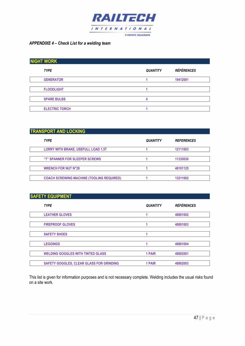
APPENDIXE 4 – Check List for a welding team
ADJUSTMENT OF RAILS TYPE QUANTITY RÉFÉRENCES
HC 355 RAIL SAW 2 14221022
DISC 355 X 3.6 X 25.4 6 47901024
STRAIGHT EDGE 1M 1 19123001
1M BEVELLED STRAIGHT EDGE 1 19123002
“A” FRAME ALIGNER 1 PAIR 11115002
GAUGE TIE RODS FOR CURVE RADIUS < 350M 1 PAIR
WOODEN EDGE 20 11114002
WELDING TYPE QUANTITY REFERENCES
WELD SHEARING MACHINE TYPE RAG 1 11332006
RAG BLADES 1 PAIR 11335030
GRINDING TYPE QUANTITY RÉFÉRENCES
FLEXIBLE SHAFT RAIL TRACK GRINDING MACHINE 1
OR
TWO-WHEEL FLEXIBLE SHAFT GRINDING MACHINE FOR ROLLING ON TRACK 1
FLEXIBLE SHAFT 1 14341002
RAPID COUPLING 2 14342002
GRINDING LAPIDARY HEAD 1 14343013
DISC GUARD 115 X 50 1 14343006
GRINDING WHEEL 115 X 50 WITH COUNTERSUNK NUT 1 47901006
OR
DISC GUARD 150 X 40 1 14343007
GRINDING WHEEL 150 X 40 WITH COUNTERSUNK NUT 1 47901009
1 M BEVELLED STRAIGHT EDGE 1 19123005
47 | P a g e
APPENDIXE 4 – Check List for a welding team
NIGHT WORK TYPE QUANTITY RÉFÉRENCES
GENERATOR 1 19412001
FLOODLIGHT 1
SPARE BULBS 4
ELECTRIC TORCH 1
TRANSPORT AND LOCKING TYPE QUANTITY REFERENCES
LORRY WITH BRAKE, USEFULL LOAD 1,5T 1 12111003
“T” SPANNER FOR SLEEPER SCREWS 1 11335030
WRENCH FOR NUT N°28 1 48101125
COACH SCREWING MACHINE (TOOLING REQUIRED) 1 13211002
SAFETY EQUIPMENT TYPE QUANTITY RÉFÉRENCES
LEATHER GLOVES 1 48801002
FIREPROOF GLOVES 1 48801003
SAFETY SHOES 1
LEGGINGS 1 48801004
WELDING GOGGLES WITH TINTED GLASS 1 PAIR 48802001
SAFETY GOGGLES, CLEAR GLASS FOR GRINDING 1 PAIR 48802003
This list is given for information purposes and is not necessary complete. Welding includes the usual risks found on a site work.

48 | P a g e
Appendix 5 / Line of preheating RAILTECH
LIG
NE
DE
PR
EC
HA
UF
FA
GE
OX
Y-P
RO
PA
NE
RA
ILT
EC
H 2
2 T
RO
US
VE
RS
ION
C
OX
Y-P
RO
PA
NE
PR
EH
EA
TIN
G L
INE
RA
ILT
EC
H 2
2 H
OL
ES
VE
RS
ION
C
Ho
se P
rop
ane
8mm
Bo
re x
20m
lo
ng
3/8
BS
P t
o 9
/16
UN
F N
ut L
/HT
uyau
Pro
pane
Ø 8
mm
, Lo
ngue
ur 2
0mR
éfér
ence
Har
ris
: H22
32
Gau
ge
8E68
6 0-
2.5
bar
gas
Man
omèt
re
gaz
Réf
éren
ce H
arri
s : H
2223
OX
YP
RO
PA
NE
BL
OW
TOR
CH
RA
ILTE
CH
22
HO
LE
S
CH
AL
UM
EA
U R
AIL
TEC
H 2
2 TR
OU
S P
réch
auff
age
oxy
-pro
pan
eR
éfér
ence
Rai
ltec
h :
1123
1007
OX
YG
EN
AC
ET
YL
EN
E
Fla
sh g
uar
d H
arri
s 88
-6C
VTR
Oxy
gen
Cla
pet
antir
etou
r H
arris
88-
6CV
TR
R
éfér
ence
Rai
ltec
h :
4830
2005
Ref
eren
ce H
arri
s : H
4018
Reg
ula
tor O
xyg
en M
od
el 9
96 1
0.0
bar
Man
odét
ende
ur O
xygè
neR
éfér
ence
Har
ris
:H10
43
Fla
shb
ack
Arr
esto
r H
arri
s
Mo
del
188
-2TR
GB
Oxy
gen
Cla
pet
pare
flam
me
oxyg
ène
Réf
éren
ce H
arri
s : H
1307
Ho
se O
xyg
en 1
0mm
bo
re x
20m
lo
ng
3/8
BS
P t
o 9
/16
UN
F n
ut R
/HT
uyau
Oxy
gène
Ø 1
0mm
, Lo
ngue
ur 2
0mR
éfér
ence
Har
ris
: H22
31
Reg
ula
tor P
rop
ane
mo
del
896
4.0
bar
Man
odét
ende
ur P
ropa
neR
éfér
ence
Har
rish
: H
1029
Fla
sh g
uar
d H
arri
s 88
-6C
VTL
Fu
el G
as
Cla
pet
antir
etou
r H
arris
88-
6CV
TL
Réf
éren
ce R
ailt
ech
:48
3020
06R
éfér
ence
Har
ris
: H40
17
T-p
iece
in li
ne
9/16
BS
P L
/H
Té
gaz
Réf
éren
ce H
arri
s : H
2222
RTI
Har
ris
F43
Pro
pan
e M
ixer
Mél
ange
ur R
TI H
arris
F43
Pro
pane
Réf
éren
ce R
ailt
ech
: 48
3020
03
RA
ILTE
CH
22
Ho
les
Pre
-Hea
ter
Bus
e A
llong
e R
TI 2
2 T
rous
Réf
éren
ce R
ailt
ech
: 35
9102
29
Gau
ge
8E66
1 0-
6.0
bar
Oxy
gen
Man
omèt
re O
xygè
neR
éfér
ence
Har
ris:
H52
00 T-p
iece
in li
ne
9/16
BS
P R
/H
Té
Oxy
gène
R
éfér
ence
Har
ris:
H22
21
Har
ris
Mo
del
K:4
3-2
Sh
ank
Man
che
Har
ris M
odel
K:4
3-2
Réf
éren
ce R
ailt
ech
: 48
3020
04R
efer
ence
Har
ris
: H21
25
Fla
shb
ack
Arr
esto
r G
as M
od
el 1
88-2
TLG
B
Cla
pet
pare
flam
me
Gaz
Réf
éren
ce H
arri
s : H
1308
Det
ails
of t
he
no
zzle
22
Ho
les
Dét
ails
de
la b
use
22 T
rous
Ru
bb
erco
ver
for g
aug
e
Pro
ctec
tion
pour
man
omèt
reR
éfér
ence
Har
ris
: H52
32
H=70mm
H=50mm
Det
ail o
f th
e P
re-H
eate
r H
old
er
for
hei
gh
t ad
just
men
tD
étai
l du
sup
port
de c
halu
mea
upo
ur le
rég
lage
de
la h
aute
ur
Pre
-Hea
ter
Ho
lder
RA
ILTE
CH
22
Ho
les
Pie
d su
ppor
t de
chal
umea
u R
AIL
TE
CH
22
Tro
us
Fo
r w
idth
of
rail
hea
d <
80m
m
Pou
r un
e la
rgeu
r de
cha
mpi
gnon
<80
mm
Réf
éren
ce R
ailt
ech
: 11
2340
03
Fo
r w
idth
of
rail
hea
d >
80m
mP
our
une
larg
eur
de c
ham
pign
on >
80m
mR
éfér
ence
Rai
ltec
h :
1123
4004


![Cambridge IGCSE Biology - Mackean, D. G [SRG].pdf](https://img.pdfslide.us/doc/110x75/563dbb6f550346aa9aad23a7/cambridge-igcse-biology-mackean-d-g-srgpdf.jpg)