Embed Size (px)
Citation preview

GRUNDFOS PRODUCT GUIDE
S pumps, range 62
54 to 79 hp60 Hz ANSI

Contents
2
IntroductionIntroduction 3Applications 3Main constructional features 4
Performance rangePerformance range, S pumps 5Performance range, S pumps, range 62 5
IdentificationType key 6Pump nameplate 7FM approval plate 7
Selection of productOrdering a pump 8
Product rangeStandard range 9Explosion-proof pumps 11
VariantsList of variants 13
ConstructionSectional drawings, motors 14Sectional drawings, pumps 18Components and material specification 24
Product descriptionFeatures 25Operating conditions 26Motor range 26Explosion-proof pumps 27Pump controllers 27Wiring diagrams 28
Curve charts/Technical dataHow to read the curve charts 30Curve conditions 31Performance tests 31Certificates 31Witness test 31
Performance curvesTechnical dataS 62 low pressure, 4-pole 32S 62 low pressure, 4-pole 34S 62 medium pressure, 4-pole 36S 62 medium pressure, 4-pole 38S 62 high pressure, 4-pole 40S 62 high pressure, 4 pole 42
AccessoriesAccessories (for installation) 44Other accessories 45
DimensionsInstallation on auto coupling 46Dry, vertical installation 50Dry, horisontal installation 52
Further product documentationWebCAPS 54WinCAPS 55

S pumps, range 62Introduction
IntroductionThis product guide deals with Grundfos heavy-duty sewage pumps called S pumps, range 62.
This product guide was printed in July 2010. A newer version might be available from Grundfos WebCAPS. Go to WebCAPS Literature to locate and download the latest version - or insert the link below directly in your browser to get to the download page:
http://net.grundfos.com/Appl/WebCAPS/
Using the PDF version of this data booklet offers extra features to the booklet. Double-clicking a product number listed in the data booklet will open an internet browser window displaying all technical information available on the product.
Fig. 1 S pump, range 62
The S pumps, range 62, are a range of free-flow chan-nel impeller pumps specifically designed for pumping sewage and wastewater in a wide range of municipal, private and industrial applications.
The pumps are made of resistant materials, such as cast iron and stainless steel. These materials ensure a proper operation.
The pumps are fitted with motors from 54 hp up to 79 hp (40 kW up to 52 kW). The motors are 4-pole motors, depending on the motor size.
The free passage in the pumps is 3 to 4" (80 to 100 mm).
The pumps are available for:
• submerged installation on auto-coupling system• submerged installation, free-standing• ry-pit installation, vertical• dry-pit installation, horizontal.
ApplicationsThe S pumps, range 62, are designed for applications, such as:
• raw water intake• wastewater treatment plants• municipal pumping stations • public buildings • residential housing• blocks of apartments• industries• parking garages • underground car parks • car wash areas • restaurants and hotels. The pumps are suitable for both temporary and perma-nent installation. The lifting bracket fitted on the pumps facilitates easy transportation to as well as installation at the installation site.
RrA
7836
3

Introduction S pumps, range 62
4
Main constructional features• leak-proof connections via the Grundfos SmartSeal
gasket system• double mechanical shaft seal system for reliable
sealing between pumped liquid and motor• watertight cable entry of corrosion-resistant polya-
mide or cast iron for FM approved pumps• moisture switch for continuous monitoring of motor
housing and automatic cut-off of power in case liq-uid penetrates
• self-cleaning channel impeller with long vanes re-ducing the risk of jamming or clogging, or SuperVor-tex impeller with high pumping efficency and less downtime
• SmartTrim system allowing easy adjustment of im-peller clearance and maintaining maximum pump efficiency over pump lifetime
• motor in insulation class H (356 °F (180 °C)), enclo-sure class IP68 with three thermal sensors in stator windings
• seal condition monitoring via water-in-oil sensor (optional)
• explosion-proof motors for applications involving high risk of explosion
• stainless steel versions for use in corrosive or ag-gressive liquids:Q: stainless steel impeller, cast iron pump and mo-tor housing.

S pumps, range 62
5
Performance range
Performance range, S pumps
Performance range, S pumps, range 62
TM04
655
7 06
10
100 150 200 300 400 500 8001000 1500 2000 3000 5000 10000 15000
Q [US GPM]
6
8
10
15
20
30
40
60
80
100
150
200
300
[ft]H
1010 20 30 40 50 60 7080 100100 200 300 400 600 800Q [l/s]
2
3
4
5
6
8
1010
20
30
40
50
60
80
[m]H
60 Hz
50
54
58
62
66
70
20000
TM04
660
8 06
10
0 500 1000 1500 2000 2500 3000 3500 4000 4500 5000
Q [US GPM]
15
20
25
30
40
50
60
70
80
100
150
200
250
[ft]H
0 50 100 150 200 250 Q [l/s]
5
6
7
8
9
1010
20
30
40
50
60
70
[m]H
60 Hz
S PumpsRange 62
S1.40.A50
S2.40.A80
S1.30.A50

6
S pumps, range 62Identification
Type keyCode Example S 1 .30 .A50 .540 4 .62H .S .320 .G .N .D
SST
Pump type:Grundfos sewage and wastewater pumpMulti-channel impeller pump installed in a column pipe
1V
Impeller type:Single-channel impellerSuperVortex (free-flow) impeller
Pump passage:Maximum solids size = Code number from type designation/10 [inch]
A50
Pump discharge:Nominal diameter of pump discharge port = Code number from type designation/10 [inch]5"
Output power, P2:P2 = Code number from type designation/10 [hp]
4Number of poles: 4-pole motor
62H62M62L
Pump range / Pressure version:High pressureMedium pressureLow pressure
SCDH
Installation:Submersible installation without cooling jacketSubmersible installation with cooling jacketDry installation, verticalDry installation, horizontal.
Actual impeller diameter:[mm]
GQ
Material code for impeller, pump and motor housing:Impeller, pump housing and motor housing: Cast ironImpeller: Stainless steel AISI 316 (DIN W.-Nr. 1.4408)
NEx
Pump version:Non-explosion-proof pumpExplosion-proof pump
BCD
Sensor version:B = S pump with built-in SM 111 module. PTC sensors are connected directly to IO 111 or other PTC relay.C = Not in useD = S pump without built-in SM 111 module.
Z Custom-built products

Identification S pumps, range 62
Pump nameplate
Fig. 2 Pump nameplate
FM approval plate
Fig. 3 Ex approval plate
The approval plate gives the following details:
TM04
649
4 12
10
Pos. Description
1 Type designation2 SAP code 3 Serial number4 Maximum ambient temperature5 Maximum head6 Maximum flow7 Maximum installation depth8 Enclosure class9 Number of phases
10 Frequency11 Rated speed12 Voltage/current, delta connection13 Voltage/current, star connection14 Power input/output15 Service factor16 Power factor17 Insulation class18 Production code, year/week19 Weight of the pump20 Model
2
1
3579
1013141618
20468
1112
1719
15
TM04
649
5 02
10
FM symbol
II Equipment group (II = non-mining)2 Equipment category (high protection)G Type of explosive atmosphereCE CE mark1180 Number of quality assurance notified bodyEx Motor explosion-proof according to FM standardb Control of ignition sourcesc Constructional safetyd Motor withstands explosion pressureIIB Gas group (Ethylene)T3C Maximum surface temperature of the motor is
320 °F (160 °C)T4 Maximum surface temperature of the motor is
275 °F (135 °C)Gb Equipment protection level, zone 1Baseefa Certificate numberFM Certificate number
FM
7

S pumps, range 62
8
Selection of product
Ordering a pumpWhen ordering an S pump, range 62, you need to take the following four aspects into consideration.
1. Pump2. Custom-built variation (option)3. Accessories4. Controller.
PumpUse the selection tool in WebCAPS to find the best suited pump for your application or use the section Product range on page 9 and the section Type key on page 6 to identify the pump that best fulfils your needs. The list below is a detailed description of the product you get if you order the following pump:
• Pump as specified in the type key• 50 ft (15 m) cable• Paint: Graphic grey, NCS S8005-R80B, thickness
150 μ • Three thermal switches (Klixon), one in each phase,
or three thermal sensors (PTC)• One moisture switch below the motor top cover (two
moisture switches below the motor top cover on explosion-proof versions)
• ANSI-HI centrifugal pump test 1.6-2000, Acceptance level B.
See section Performance curves Technical data for selection of a standard pump.
Note: Product specific data for the pump can also be seen in WebCAPS using the product number 97632183.
Custom-built variantsThe S pumps can be customised to meet individual requirements. Many pump features and options are available for customisation, e.g. explosion-proof versions, various cable lengths or special materials.
Variants can be seen in section List of variants on page 13. For requirements or designs not included in the list, contact Grundfos.
AccessoriesDepending on the installation type, you may need to order accessories. See section Accessories on page 44 for selection of the correct accessories.
Note: Ordered accessories are not fitted from factory.
ControllerThe following controllers are available:
Grundfos Dedicated Controls (DC).Pump Product noS1.30.A50.540.4.62H.S.320.G.N.D 97632183

S pumps, range 62Product range
Standard range
* Wi hout hose connection.** Installation type S and C pumps with discharge flange size 10" (DN 250) and higher are supplied with guide claw mounted on the flange.*** The horizontal base stand is included in the pump product number.
Pump type Pump
Accessories
*** Horizontal base stand
To be ordered separatelyVertical base
stand** Auto-coupling
system* Ring stand for
portable useS1.30.A50.540.4.62H.S.320.G.N.D.611 97632183 - - 97626242 -S1.30.A50.540.4.62H.C.320.G.N.D.611 97632184 - - 97626242 -S1.30.A50.540.4.62H.D.320.G.N.D.611 97632185 - 96308238 - -S1.30.A50.540.4.62H.H.320.G.N.D.611 97632186 96787496 - - -S1.40.A50.540.4.62M.S.292.G.N.D.611 97632187 - - 97626242 -S1.40.A50.540.4.62M.C.292.G.N.D.611 97632188 - - 97626242 -S1.40.A50.540.4.62M.D.292.G.N.D.611 97632189 - 96094523 - -S1.40.A50.540.4.62M.H.292.G.N.D.611 97632190 96787497 - - -S1.30.A50.640.4.62H.S.334.G.N.D.611 97632191 - - 97626242 -S1.30.A50.640.4.62H.C.334.G.N.D.611 97632192 - - 97626242 -S1.30.A50.640.4.62H.D.334.G.N.D.611 97632193 - 96308238 - -S1.30.A50.640.4.62H.H.334.G.N.D.611 97632194 96787496 - - -S2.40.A80.540.4.62L.S.245.G.N.D.611 97632195 - - 97506541 -S2.40.A80.540.4.62L.C.245.G.N.D.611 97632196 - - 97506541 -S2.40.A80.540.4.62L.D.245.G.N.D.611 97632197 - 96856263 - -S2.40.A80.540.4.62L.H.245.G.N.D.611 97632198 96857521 - - -S2.40.A80.640.4.62L.S.285.G.N.D.611 97632199 - - 97506541 -S2.40.A80.640.4.62L.C.285.G.N.D.611 97632200 - - 97506541 -S2.40.A80.640.4.62L.D.285.G.N.D.611 97632201 - 96856263 - -S2.40.A80.640.4.62L.H.285.G.N.D.611 97632202 96857521 - - -S1.40.A50.640.4.62M.S.308.G.N.D.611 97632203 - - 97626242 -S1.40.A50.640.4.62M.C.308.G.N.D.611 97632204 - - 97626242 -S1.40.A50.640.4.62M.D.308.G.N.D.611 97632205 - 96094523 - -S1.40.A50.640.4.62M.H.308.G.N.D.611 97632206 96787497 - - -S1.40.A50.790.4.62M.S.326.G.N.D.611 97632207 - - 97626242 -S1.40.A50.790.4.62M.C.326.G.N.D.611 97632208 - - 97626242 -S1.40.A50.790.4.62M.D.326.G.N.D.611 97632209 - 96094523 - -S1.40.A50.790.4.62M.H.326.G.N.D.611 97632210 96787497 - - -S2.40.A80.790.4.62L.S.272.G.N.D.611 97632211 - - 97506541 -S2.40.A80.790.4.62L.C.272.G.N.D.611 97632212 - - 97506541 -S2.40.A80.790.4.62L.D.272.G.N.D.611 97632213 - 96856263 - -S2.40.A80.790.4.62L.H.272.G.N.D.611 97632214 96857521 - - -S1.30.A50.790.4.62H.S.334.G.N.D.611 97632215 - - 97626242 -S1.30.A50.790.4.62H.C.334.G.N.D.611 97632216 - - 97626242 -S1.30.A50.790.4.62H.D.334.G.N.D.611 97632217 - 96308238 - -S1.30.A50.790.4.62H.H.334.G.N.D.611 97632218 96787496 - - -
9

Product range S pumps, range 62
10
Standard range with stainless steel impel- ler
* Wi hout hose connection.** Installation type S and C pumps with discharge flange size 10" (DN 250) and higher are supplied with guide claw mounted on the flange.*** The horizontal base stand is included in the pump product number.
Pump type Pump
Accessories
*** Horizontal base stand
To be ordered separatelyVertical base
stand** Auto-coupling
system* Ring stand for
portable useS1.40.A50.540.4.62M.S.292.Q.N.D.611 97647777 - - 97626242 -S1.40.A50.540.4.62M.C.292.Q.N.D.611 97647778 - - 97626242 -S1.40.A50.540.4.62M.D.292.Q.N.D.611 97647779 - 96094523 - -S1.40.A50.540.4.62M.H.292.Q.N.D.611 97647780 96787497 - - -S2.40.A80.540.4.62L.S.245.Q.N.D.611 97647841 - - 97506541 -S2.40.A80.540.4.62L.C.245.Q.N.D.611 97647842 - - 97506541 -S2.40.A80.540.4.62L.D.245.Q.N.D.611 97647843 - 96856263 - -S2.40.A80.540.4.62L.H.245.Q.N.D.611 97647844 96857521 - - -S2.40.A80.640.4.62L.S.285.Q.N.D.611 97647845 - - 97506541 -S2.40.A80.640.4.62L.C.285.Q.N.D.611 97647846 - - 97506541 -S2.40.A80.640.4.62L.D.285.Q.N.D.611 97647847 - 96856263 - -S2.40.A80.640.4.62L.H.285.Q.N.D.611 97647848 96857521 - - -S1.40.A50.640.4.62M.S.308.Q.N.D.611 97647849 - - 97626242 -S1.40.A50.640.4.62M.C.308.Q.N.D.611 97647850 - - 97626242 -S1.40.A50.640.4.62M.D.308.Q.N.D.611 97647851 - 96094523 - -S1.40.A50.640.4.62M.H.308.Q.N.D.611 97647852 96787497 - - -S1.40.A50.790.4.62M.S.326.Q.N.D.611 97647853 - - 97626242 -S1.40.A50.790.4.62M.C.326.Q.N.D.611 97647854 - - 97626242 -S1.40.A50.790.4.62M.D.326.Q.N.D.611 97647855 - 96094523 - -S1.40.A50.790.4.62M.H.326.Q.N.D.611 97647856 96787497 - - -S2.40.A80.790.4.62L.S.272.Q.N.D.611 97647857 - - 97506541 -S2.40.A80.790.4.62L.C.272.Q.N.D.611 97647858 - - 97506541 -S2.40.A80.790.4.62L.D.272.Q.N.D.611 97647859 - 96856263 - -S2.40.A80.790.4.62L.H.272.Q.N.D.611 97647860 96857521 - - -S1.30.A50.790.4.62H.S.334.Q.N.D.611 97647861 - - 97626242 -S1.30.A50.790.4.62H.C.334.Q.N.D.611 97647862 - - 97626242 -S1.30.A50.790.4.62H.D.334.Q.N.D.611 97647863 - 96308238 - -S1.30.A50.790.4.62H.H.334.Q.N.D.611 97647864 96787496 - - -S1.30.A50.540.4.62H.S.320.Q.N.D.611 97654006 - - 97626242 -S1.30.A50.540.4.62H.C.320.Q.N.D.611 97654007 - - 97626242 -S1.30.A50.540.4.62H.D.320.Q.N.D.611 97654008 - 96308238 - -S1.30.A50.540.4.62H.H.320.Q.N.D.611 97654009 96787496 - - -S1.30.A50.640.4.62H.S.334.Q.N.D.611 97654010 - - 97626242 -S1.30.A50.640.4.62H.C.334.Q.N.D.611 97654021 - - 97626242 -S1.30.A50.640.4.62H.D.334.Q.N.D.611 97654026 - 96308238 - -S1.30.A50.640.4.62H.H.334.Q.N.D.611 97654028 96787496 - - -

Product range S pumps, range 62
Explosion-proof pumps
Explosion proof range
* Wi hout hose connection.** Installation type S and C pumps with discharge flange size 10" (DN 250) and higher are supplied with guide claw mounted on the flange.*** The horizontal base stand is included in the pump product number.
Pump type Pump
Accessories
*** Horizontal base stand
To be ordered separately
Vertical base stand
** Auto-coupling system
* Ring stand for portable
useS1.30.A50.540.4.62H.S.320.G.Ex.D 97660708 - - 97626242 -S1.30.A50.540.4.62H.C.320.G.Ex.D 97660709 - - 97626242 -S1.30.A50.540.4.62H.D.320.G.Ex.D 97660710 - 96308238 - -S1.30.A50.540.4.62H.H.320.G.Ex.D 97660731 96787496 - - -S1.40.A50.540.4.62M.S.292.G.Ex.D 97660732 - - 97626242 -S1.40.A50.540.4.62M.C.292.G.Ex.D 97660733 - - 97626242 -S1.40.A50.540.4.62M.D.292.G.Ex.D 97660734 - 96094523 - -S1.40.A50.540.4.62M.H.292.G.Ex.D 97660735 96787497 - - -S1.30.A50.640.4.62H.S.334.G.Ex.D 97660736 - - 97626242 -S1.30.A50.640.4.62H.C.334.G.Ex.D 97660737 - - 97626242 -S1.30.A50.640.4.62H.D.334.G.Ex.D 97660738 - 96308238 - -S1.30.A50.640.4.62H.H.334.G.Ex.D 97660739 96787496 - - -S2.40.A80.540.4.62L.S.245.G.Ex.D 97660740 - - 97506541 -S2.40.A80.540.4.62L.C.245.G.Ex.D 97660741 - - 97506541 -S2.40.A80.540.4.62L.D.245.G.Ex.D 97660742 - 96856263 - -S2.40.A80.540.4.62L.H.245.G.Ex.D 97660743 96857521 - - -S2.40.A80.640.4.62L.S.285.G.Ex.D 97660744 - - 97506541 -S2.40.A80.640.4.62L.C.285.G.Ex.D 97660745 - - 97506541 -S2.40.A80.640.4.62L.D.285.G.Ex.D 97660746 - 96856263 - -S2.40.A80.640.4.62L.H.285.G.Ex.D 97660747 96857521 - - -S1.40.A50.640.4.62M.S.308.G.Ex.D 97660748 - - 97626242 -S1.40.A50.640.4.62M.C.308.G.Ex.D 97660749 - - 97626242 -S1.40.A50.640.4.62M.D.308.G.Ex.D 97660750 - 96094523 - -S1.40.A50.640.4.62M.H.308.G.Ex.D 97660751 96787497 - - -S1.40.A50.790.4.62M.S.326.G.Ex.D 97660752 - - 97626242 -S1.40.A50.790.4.62M.C.326.G.Ex.D 97660753 - - 97626242 -S1.40.A50.790.4.62M.D.326.G.Ex.D 97660754 - 96094523 - -S1.40.A50.790.4.62M.H.326.G.Ex.D 97660755 96787497 - - -S2.40.A80.790.4.62L.S.272.G.Ex.D 97660756 - - 97506541 -S2.40.A80.790.4.62L.C.272.G.Ex.D 97660757 - - 97506541 -S2.40.A80.790.4.62L.D.272.G.Ex.D 97660758 - 96856263 - -S2.40.A80.790.4.62L.H.272.G.Ex.D 97660759 96857521 - - -S1.30.A50.790.4.62H.S.334.G.Ex.D 97660760 - - 97626242 -S1.30.A50.790.4.62H.C.334.G.Ex.D 97660761 - - 97626242 -S1.30.A50.790.4.62H.D.334.G.Ex.D 97660762 - 96308238 - -S1.30.A50.790.4.62H.H.334.G.Ex.D 97660763 96787496 - - -
11

Product range S pumps, range 62
12
Explosion proof range with stainless steel impeller
* Wi hout hose connection.** Installation type S and C pumps with discharge flange size 10" (DN 250) and higher are supplied with guide claw mounted on the flange.*** The horizontal base stand is included in the pump product number.
Pump type Pump
Accessories
*** Horizontal base stand
To be ordered separatelyVertical base
stand** Auto-coupling sys-
tem* Ring stand for
portable useS1.30.A50.540.4.62H.S.320.Q.Ex.D 97663708 - - 97626242 -S1.30.A50.540.4.62H.C.320.Q.Ex.D 97663709 - - 97626242 -S1.30.A50.540.4.62H.D.320.Q.Ex.D 97663710 - 96308238 - -S1.30.A50.540.4.62H.H.320.Q.Ex.D 97663721 96787496 - - -S1.40.A50.540.4.62M.S.292.Q.Ex.D 97663722 - - 97626242 -S1.40.A50.540.4.62M.C.292.Q.Ex.D 97663723 - - 97626242 -S1.40.A50.540.4.62M.D.292.Q.Ex.D 97663724 - 96094523 - -S1.40.A50.540.4.62M.H.292.Q.Ex.D 97663725 96787497 - - -S1.30.A50.640.4.62H.S.334.Q.Ex.D 97663726 - - 97626242 -S1.30.A50.640.4.62H.C.334.Q.Ex.D 97663727 - - 97626242 -S1.30.A50.640.4.62H.D.334.Q.Ex.D 97663728 - 96308238 - -S1.30.A50.640.4.62H.H.334.Q.Ex.D 97663729 96787496 - - -S2.40.A80.540.4.62L.S.245.Q.Ex.D 97663730 - - 97506541 -S2.40.A80.540.4.62L.C.245.Q.Ex.D 97663741 - - 97506541 -S2.40.A80.540.4.62L.D.245.Q.Ex.D 97663742 - 96856263 - -S2.40.A80.540.4.62L.H.245.Q.Ex.D 97663743 96857521 - - -S2.40.A80.640.4.62L.S.285.Q.Ex.D 97663744 - - 97506541 -S2.40.A80.640.4.62L.C.285.Q.Ex.D 97663745 - - 97506541 -S2.40.A80.640.4.62L.D.285.Q.Ex.D 97663747 - 96856263 - -S2.40.A80.640.4.62L.H.285.Q.Ex.D 97663748 96857521 - - -S1.40.A50.640.4.62M.S.308.Q.Ex.D 97663749 - - 97626242 -S1.40.A50.640.4.62M.C.308.Q.Ex.D 97663750 - - 97626242 -S1.40.A50.640.4.62M.D.308.Q.Ex.D 97663751 - 96094523 - -S1.40.A50.640.4.62M.H.308.Q.Ex.D 97663752 96787497 - - -S1.40.A50.790.4.62M.S.326.Q.Ex.D 97663753 - - 97626242 -S1.40.A50.790.4.62M.C.326.Q.Ex.D 97663754 - - 97626242 -S1.40.A50.790.4.62M.D.326.Q.Ex.D 97663755 - 96094523 - -S1.40.A50.790.4.62M.H.326.Q.Ex.D 97663756 96787497 - - -S2.40.A80.790.4.62L.S.272.Q.Ex.D 97663757 - - 97506541 -S2.40.A80.790.4.62L.C.272.Q.Ex.D 97663758 - - 97506541 -S2.40.A80.790.4.62L.D.272.Q.Ex.D 97663759 - 96856263 - -S2.40.A80.790.4.62L.H.272.Q.Ex.D 97663760 96857521 - - -S1.30.A50.790.4.62H.S.334.Q.Ex.D 97663761 - - 97626242 -S1.30.A50.790.4.62H.C.334.Q.Ex.D 97663762 - - 97626242 -S1.30.A50.790.4.62H.D.334.Q.Ex.D 97663763 - 96308238 - -S1.30.A50.790.4.62H.H.334.Q.Ex.D 97663764 96787496 - - -

S pumps, range 62
13
Variants
List of variantsMotor
Various cable lengths82 ft (25 m)165 ft (50 m)
EMC power cables Screened power cables for variable speed drives
33 ft (10 m)50 ft (15 m)82 ft (25 m)165 ft (50 m)
Special motor Special voltagePTC thermistors in windingsSpecial oil Non-toxic Shell Ondina 917
Motor protectionPTC + moisture switch FPV1Klixon + moisture switch + WIO FPV2aPTC + moisture switch + WIO FPV2bKlixon + moisture switch + WIO + PT100 at lower and upper bearing FPV4aPTC + moisture switch + WIO + PT100 at lower and upper bearing FPV4b
MaterialsStainless steel lifting bracket AISI 316Stainless steel impeller Variant QStainless steel impeller and pump housing Variant S Stainless steel Impeller, pump housing and motor housing Variant R
Tests
Test at specified duty on standard impeller curve
Trimmed impeller for specified duty test Additional test of entire QH curve (incl. report) 5-10 flows from pump performance curve
Different test standard Efficiency guaranteed by GrundfosISO 9906 grade 1 tolerancesISO 9906 grade 2 tolerances
Vibration test (incl. report) According to Grundfos factory quality standardPerformance test on dry test stand Not yet availableNPSHr test Not yet availableString test Contact GrundfosWitness test Contact Grundfos
MiscellaneousSpecial packaging Contact GrundfosSpecial nameplate Contact GrundfosOther variants Contact Grundfos

14
S pumps, range 62Construction
Sectional drawings, motors
Fig. 4 Non-explosion-proof motor without cooling jacket
TM04
230
6 23
08

Construction S pumps, range 62
Fig. 5 Non-explosion-proof motor with cooling jacket
TM04
230
7 23
08
15

Construction S pumps, range 62
16
Fig. 6 Explosion-proof motor without cooling jacket
TM04
230
8 23
08

Construction S pumps, range 62
Fig. 7 Explosion-proof motor with cooling jacket
TM04
230
9 23
08
17

Construction S pumps, range 62
18
Sectional drawings, pumps
Fig. 8 S1 pump
TM04
231
0 23
08

Construction S pumps, range 62
Fig. 9 SV pump
TM04
231
1 23
08
19

Construction S pumps, range 62
20
Fig. 10 S1 pump with DN 2 > DN 400
TM04
231
2 23
08
Construction S pumps, range 62
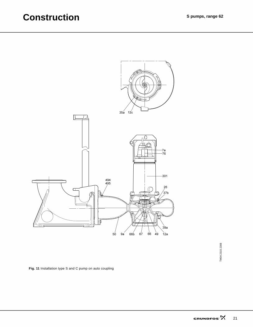
Fig. 11 Installation type S and C pump on auto coupling
TM04
231
5 23
08
21

Construction S pumps, range 62
22
Fig. 12 Installation type D pump
TM04
231
6 23
08
731

Construction S pumps, range 62
Fig. 13 S1 pump, installation type H
Fig. 14 SV pump, installation type H
TM04
231
3 23
08TM
04 2
314
2308
23

Construction S pumps, range 62
24
Components and material specification
Motor
Pump
Accessories
* Ex versions have cast iron cable entry and two moisture switches.** Available of stainless steel (custom-built option).
Pos. Component Material (AISI/DIN W.-Nr.)7a Rivet Stainless steel (316/1.4436)
25a Screw Stainless steel (316/1.4436)
25 Pressure test plug Stainless steel (316/1.4436)
48 Stator lamination
**55 Stator housing Cast iron (EN-JL 1040/A48 30)
58 Seal housing Cast iron
60 Bearing bracket cover Cast iron
61c Upper bearing bracket Cast iron
72a O-ring NBR rubber
72 O-ring NBR rubber
76a Approval plate
100 O-ring NBR rubber
105b Mechanical seal SiC/SiC or SiC/carbon
105 Mechanical seal SiC/SiC or SiC/carbon
150c Cooling jacket Galvanised steel
153 Ball bearing Stainless steel
154 Ball bearing Stainless steel
**155 Lower bearing bracket Cast iron
157b O-ring NBR rubber
157 O-ring NBR rubber
**164a Motor top cover Cast iron
*168 Cable entry PA or cast iron
172 Shaft with rotor Stainless steel (329/1.4462)
173b Earth terminal
173c Washer Stainless steel (316/1.4436)
173e Screw Stainless steel (316/1.4436)
173f Spring washer Stainless steel (316/1.4436)
173g Earth connector
173 Screw Stainless steel (316/1.4436)
176a Terminal block
176b Screw Stainless steel (316/1.4436)
176c Terminal block
176d Terminal block
178 Screw Stainless steel (316/1.4436)
180 Cable clamp PA or cast iron
181a Screw Stainless steel (316/1.4436)
181 Cable ATON
182b Hexagon socket head cap screw Stainless steel (316/1.4436)
184b Screw Stainless steel (316/1.4436)
184 Screw Stainless steel (316/1.4436)
187a Washer Stainless steel (316/1.4436)
187 Circlip
188 Circlip
190 Lifting bracket Stainless steel (316/1.4408)
193 Plug Stainless steel (316/1.4408)
194 O-ring NBR rubber
197 Washer Stainless steel (316/1.4436)
198 Rubber seal
248 Screw Stainless steel (316/1.4436)
250a Cable entry PA or cast iron
250b Rubber seal
250 Cable clamp PA or cast iron
252 Cable ATON
520a Screw Stainless steel (316/1.4436)
520b Nut Stainless steel (316/1.4436)
*520 Moisture switch
522 Holder
Pos. Component Material (AISI/DIN W.-Nr.)7a Rivet
9a Key (for keyway) Stainless steel (316/1.4436)
12c Adjusting screw Stainless steel (316/1.4436)
26 Screw Stainless steel (316/1.4436)
37 O-ring NBR rubber
37b O-ring NBR rubber
**49 Impeller Cast iron EN-JL 1050
**50 Volute casing Cast iron EN-JS 1050
67 Impeller screw Stainless steel (316/1.4436)
76 Nameplate
301 Motor housing
494 Plug Stainless steel (316/1.4436)
495 O-ring NBR rubber
Pos. Component Material
**701 Auto-coupling base unit Cast iron
**702 Guide rail bracket Cast iron
**703 Guide claw Cast iron
731 Base stand, vertical Galvanised steel
749 Bend Cast iron
**761 Hose connector Cast iron or stainless steel
487 Base stand, horizontal Galvanised steel
799 Anchor bolt
Pos. Component Material (AISI/DIN W.-Nr.)

S pumps, range 62Product description
FeaturesSmartTrimOn conventional pumps, maintaining factory-set impeller clearance is a time-consuming and costly task. The pumps need to be disconnected from the pipework and to be totally dismantled, and new parts need to be mounted in order to maintain full pumping efficiency. Not so with Grundfos SmartTrim!
All Grundfos heavy-duty channel-impeller pumps, whether for submerged or dry installation, are equipped with the unique SmartTrim impeller clearance adjustment system. This enables you to easily restore factory-set impeller clearance and maintain peak pumping efficiency. All you need to do is to tighten the adjustment screws on the exterior of the impeller housing. This can be done on site, quickly and easily, without dismantling the pump and without using special tools.
A: With Grundfos SmartTrim impeller clearance adjustment system
B: Without impeller clearance adjustment system
SmartSealFor pumps with 10" discharge or larger, the Grundfos SmartSeal auto-coupling gasket mounted on the pump discharge flange provides a completely leak-proof connection between the pump and the base unit of the auto-coupling system. This optimises the efficiency of the entire pumping system and keeps operating costs at a minimum.
Ball bearingsThe bearings are greased for life.
Main bearings: Double-row angular contact ball bearing.
Support bearings: Single-row deep-groove ball bearing.
Shaft sealThe pumps have a shaft seal consisting of a primary and a secondary shaft seal.
The material combination of the primary shaft seal of all pump types is silicon carbide/silicon carbide. For the secondary shaft seal, the mateial combination is silicon carbide/carbon.
The shaft seals are placed in the oil chamber of the pump. The oil chamber provides reliable sealing between the pumped liquid and the motor.
The shaft seals have no springs or other parts in direct contact with the pumped liquid. This prevents rags and fibres from getting caught. The shaft seals are bidirectional, meaning that they can operate in either direction thus allowing for opposite rotation caused by back-flow of liquid through the pump.
MotorThe motor is a watertight, totally encapsulated motor with:
• insulation class H (356 °F (180 °C))• temperature rise class F (221 °F (105 °C))• enclosure class IP68.For motor protection and sensors, see section Sensors below.
Power cables
Standard cable
EMC cable
Control cable
The cables are 40 ft (15 m) long as standard. Other cable lengths are available on request. See section List of variants on page 13.
TM04
239
1 25
08
Factory-set impeller clearance
Efficiency drop in %
Years
B
A
0
3
6
9
12
15
1 2 3 4 5 Cable type[mm2]
Outer cable diameter[inch (mm)]
Bending radius
min. max. [inch (mm)]4 x 6 0.62 (15.7) 0.68 (17.2) 4.3 (110)4 x 10 0.82 (20.9) 0.92 (23.4) 5.5 (140)4 x 16 0.94 (23.8) 1.04 (26.3) 6.3 (160)
Cable type[mm2]
Outer cable diameter[inch (mm)]
Bending radius
min. max. [inch (mm)]3 x 6 0.54 (13.6) 0.6 (15.2) 3 (76)3 x 10 0.7 (17.8) 0.78 (19.8) 3.9 (99)3 x 16 0.82 (20.9) 0.9 (22.9) 4.53 (115)
Cable type[mm2]
Outer cable diameter[inch (mm)]
Bending radius
min. max. [inch (mm)]
7 x 1.5 0.57 (14.4) 0.63 - 0.65(16.0 - 16.4) 4 (100)
25

Product description S pumps, range 62
26
The number and dimension of cables depend on the motor size.
Cable entryWatertight PA or cast iron cable entry with soft shape and sealing rings to prevent damage of the cable or leaks.
SensorsAs standard the pump is equipped with:
• Three thermal switches (Klixon), one in each phase.• One moisture switch in terminal block.
Customised sensor options1. WIO (water-in-oil) sensor
The WIO sensor measures the water content in the oil and converts the value into an analogue current signal. The two sensor conductors are for power supply as well as for carrying the signal to the mea-suring device or controller. The sensor measures the water content from 0 to 20 %. It also sends a signal if the water content is outside the normal range (warning), or if there is air in the oil chamber (alarm). The sensor is fitted in a stainless steel tube for mechanical protection.The WIO sensor is connected to the Grundfos IO 111 module.
2. PVS 3 (pump vibration sensor)The vibration sensor monitors the vibration level of the pump. A change in the vibration level indicates an abnormal situation. The cause of this can be a clogged impeller, worn bearings, closed discharge valve, etc., indicating that service inspection should be carried out now in order to protect the pump or the pipe system from being damaged.
3. Bearing temperature sensor.
TestingAll pumps are tested before leaving the factory. The factory test report is based on ANSI-HI centrifugal pump test 1.6-2000, Acceptance level B. Test reports can be ordered directly with the pump or can be ordered separately based on the pump serial number.
Other tests or third party inspection certificates are available on request including HI B & A standards.See section List of variants on page 13.
Operating conditionsPumps without cooling jacket in submerged installation:• Continuous operation when pump is fully sub-
merged to top of motor.• Intermittent operation with max. 20 starts per hour
when pump is submerged to middle of motor and with short periods of operation down to the top of the pump housingNote: Explosion proof pumps must always be fully submerged
Pumps with cooling jacket in submerged and dry installation:• Continuous and intermittent operation with max. 20
starts per hour with water level down to the top of the pump housing.
Pumped liquidspH value: 4-10
Liquid temperature: 0 °C - +40 °C
When pumping liquids with a density and/or a kinematic viscosity higher than that of water, use motors with correspondingly higher outputs.
Sound pressureThe sound pressure level of the pump is lower than the limiting values stated in the EC Council directive 2006/42/EC relating to machinery (the EC Machinery Directive).
Motor range
Cable Motor power [kW]2 x 4 x 6 mm2 + 7 x 1.5 mm2 15 - 20 - 28
2 x 4 x 10 mm2 + 7 x 1.5 mm2 30 - 41 - 43
2 x 4 x 16 mm2 + 7 x 1.5 mm2 50
Shaft power [hp (kW)] No. of poles54 (40) 464 (48) 479 (59) 4

Product description S pumps, range 62
Explosion-proof pumps
Approval standardsThese pumps are approved by FM according to FM3600, FM3615 and FM3615.80.
Explanation to FM approvalThe S pumps have the following explosion protection classification: Class I, Division 1, Groups C and D, T4, T3, IP68
Pump controllersS pumps, range 62, can be controlled by Grundfos Dedicated Controls (DC).
The Grundfos Dedicated Controls system can control from one to six pumps.
The Dedicated Controls system starts/stops the S pumps by means of:
• float switches,• pressure sensor or• ultrasonic sensor.Furthermore, it is possible to control the water level by both float switches and an analog pressure sensor or ultrasonic sensor.
Optionally, it can control a mixer and/or a flush valve. The Dedicated Controls system can be extended with an IO 111 module per pump (for S pumps with built-in analog sensor).
For further settings, see the installation and operating instructions for the pump controller selected.
Standards Code Description
FM3600FM3615FM3615.80
Class I Explosive atmosphere is caused by gas or vapours.
Division 1 Area classification
Groups C and D
Classification of gases
T4/T3 Maximum surface temperature is 275 °F (135 °C) and 392 °F (200 °C)
IP68 Enclosure class according to IEC 60529.
27

Product description S pumps, range 62
28
Wiring diagrams
Fig. 15 Wiring diagrams Y-connected (460 V)
TM04
671
9 0
810
Sens
ors
Ther
mal
sw
itch
Moi
stur
e sw
itche
s
PT1
00 lo
wer
bea
ring
PT1
00 s
tato
r
Ther
mis
tor
Pow
er c
able M
otor

29

30
S pumps, range 62Curve charts/Technical data
The following many pages are divided into sections:
How to read the curve charts
Pages 30 and 31 A brief explanation of how to read the curve charts, the curve conditions, etc.
Performance curves and technical data:Page 32 Low pressurePage 36 Medium pressurePage 40 High pressure
TM04
064
2 09
08
0 200 400 600 800 1000 1200 1400 1600 1800 2000 2200 Q [US GPM]
0
20
40
60
80
100
120
140
160
180
200
220
[ft]H
0 20 40 60 80 100 120 140 160 Q [l/s]
0
10
20
30
40
50
60
[m]H
0
10
20
30
40
[ft]NPSH
62M.S
60 Hz
ISO 9906 Annex A
S1.40.A50.790.4.
S1.40.A50.790.4.
0 200 400 600 800 1000 1200 1400 1600 1800 2000 2200 Q [US GPM]
30
40
50
60
70
80
[hp]
P2
30
40
50
60
[kW]
P2
S1.40.A50.790.4.
Pump type:
62: range 62M: Pressure range (Medium pressure)S: Installation type
Total pump head H = Htotal
QH curve for the individual pump.
NPSH curve for all variants shown. When sizing the pumps, add a safety margin of at least 1.6 ft (0.5 m).
The power curves indicate shaft power [P2] for the pumps shown
Max. efficiency mark

Curve charts/Technical data
S pumps, range 62
Curve conditionsThe guidelines below apply to the curves shown in the performance charts on page 32 to page 42.
• ANSI-HI centrifugal pump test 1.6-2000, Accep-tance level B.
• The curves show pump performance with different impeller diameters at rated speed.
• The bold part of the curves show the recom-mended operating range.
• The curves apply to the pumping of airless water at a temperature of 68 °F (+20 °C) and a kinematic vis-cosity of 1 cSt (1 mm2/s).
• NPSH: The curves show average values measured under the same conditions as the performance curves.When dimensioning the pump, add a safety margin of at least 1.6 ft (0.5 m).
• In case of other densities than 133.5 ounces/gallon (1000 kg/m3), the discharge pressure is proportional to the density.
• When pumping liquids with a density higher than 133.5 ounces/gallon (1000 kg/m3), motors with cor-respondingly higher outputs must be used.
Calculation of total headThe total pump head consists of the height difference between the measuring points + the differential head + the dynamic head.
Performance testsThe requested duty point for every pump is tested according to ISO 9906, Annex A, and without certifica-tion.
In case of pumps ordered on the basis of impeller diam-eter only (no requested duty point), the pump will be tested close to the best efficiency point (BEP) of the published performance curve which is related to the ordered impeller diameter (according to ISO 9906, Annex A).
If the customer requires either more points on the curve to be checked or certain minimum performances or cer-tificates, individual measurements must be made, and a certificate can be ordered.
CertificatesCertificates have to be confirmed for every order and are available on request as follows:
• Certificate of compliance with the order (EN 10204 - 2.1)
• Pump test sheet.
Witness testWhen the pumps are being tested or are tested with a certification it is possible for the customer to witness the testing procedure according to ISO 9906.
The witness test is not a certificate and will not result in a written statement from Grundfos. The witness itself is the only guarantee that everything is carried out as pre-scribed in the testing procedure.
If the customer wants to witness test the pump perfor-mance, place this request on the order.
Hgeo: Height difference between measuring points.
Hstat: Differential head between suction and the dis-charge side of the pump.
Hdyn: Calculated values based on the velocity of the pumped liquid on the suction and the discharge side of the pump.
Htotal Hgeo Hstat Hdyn+ +=
31

32
S pumps, range 62Performance curvesTechnical data
S 62 low pressure, 4-pole
S2.40.A80.540 and S2.40.A80.640
TM04
658
1 06
10TM
04 6
580
0610
0 500 1000 1500 2000 2500 3000 3500 4000 4500 Q [US GPM]
0
20
40
60
80
100
120
[ft]H
0 50 100 150 200 250 300 Q [l/s]
0
10
20
30
[m]H
0
10
20
30
40
[ft]NPSH
62L.S
60 Hz
ISO 9906 Annex A
S2.40.A80.540.4.
S2.40.A80.640.4.
S2.40.A80.540.4.
S2.40.A80.640.4.
0 500 1000 1500 2000 2500 3000 3500 4000 4500 Q [US GPM]
10
20
30
40
50
60
70
[hp]
P2
10
20
30
40
50
[kW]
P2
S2.40.A80.540.4.
S2.40.A80.640.4.
0 200 400 600 800 1000 1200 1400 1600 1800 Q [US GPM]
0
20
40
60
80
100
120
140
160
180
200
220
[ft]H
0 20 40 60 80 100 120 Q [l/s]
0
10
20
30
40
50
60
[m]H
0
10
20
30
40
[ft]NPSH
62H.C/D/H
60 Hz
ISO 9906 Annex A
S1.30.A50.540.4.
S1.30.A50.640.4.
S1.30.A50.540.4.
S1.30.A50.640.4.
0 200 400 600 800 1000 1200 1400 1600 1800 Q [US GPM]
10
20
30
40
50
60
70
[hp]
P2
10
20
30
40
50
[kW]
P2
S1.30.A50.540.4.
S1.30.A50.640.4.

Performance curves Technical data
S pumps, range 62
Electrical data
Note: Enclosure class: IP68
Pump data
* Wi h 50 ft (15 m) cable
Pump type P1 [kW]
P2 [hp]
No. of poles RPM Starting
method
IN Istart ηmotor [%] Cos φ Moment of inertia
[lbft2 (kgm2]
Breakdown torque Mmax [lbf*ft (Nm)][A] [A] 1/2 3/4 1/1 1/2 3/4 1/1
S2.40.A80.540.4.62L 44 54 4 1770 Y/D 73 571 87 89 90 0.60 0.70 0.77 7.12 (0.3) 438.8 (595)S2.40.A80.640.4.62L 53 64 4 1764 Y/D 85 571 88 90 90 0.65 0.75 0.79 7.12 (0.3) 438.8 (595)
Pump typeMax. solids size Max. installation depth Weight *
[inch (mm)] [feet (m)] [lbs (kg)]S2.40.A80.540.4.62L.S. 4 (100) 66 (20) 1411 (640)S2.40.A80.540.4.62L.C 4 (100) 66 (20) 1543 (700)S2.40.A80.540.4.62L.D 4 (100) 66 (20) 1698 (770)S2.40.A80.540.4.62L.H 4 (100) 66 (20) 1698 (770)S2.40.A80.640.4.62L.S 4 (100) 66 (20) 1411 (640)S2.40.A80.640.4.62L.C 4 (100) 66 (20) 1543 (700)S2.40.A80.640.4.62L.D 4 (100) 66 (20) 1698 (770)S2.40.A80.640.4.62L.H 4 (100) 66 (20) 1698 (770)
33

Performance curves Technical data
S pumps, range 62
34
S 62 low pressure, 4-pole
S2.40.A80.790
TM04
683
8 06
10TM
0469
22 1
110
0 500 1000 1500 2000 2500 3000 3500 4000 4500 Q [US GPM]
0
20
40
60
80
100
120
[ft]H
0 50 100 150 200 250 300 Q [l/s]
0
10
20
30
[m]H
0
10
20
30
40
[ft]NPSH
62L.S
60 Hz
ISO 9906 Annex A
S2.40.A80.790.4.
S2.40.A80.790.4.
0 500 1000 1500 2000 2500 3000 3500 4000 4500 Q [US GPM]
30
40
50
60
70
80
[hp]
P2
30
40
50
60
[kW]
P2
S2.40.A80.790.4.
0 500 1000 1500 2000 2500 3000 3500 4000 4500 Q [US GPM]
0
20
40
60
80
100
120
[ft]H
0 50 100 150 200 250 300 Q [l/s]
0
10
20
30
[m]H
0
10
20
30
40
[ft]NPSH
62L.C/D/H
60 Hz
ISO 9906 Annex A
S2.40.A80.790.4.
S2.40.A80.790.4.
0 500 1000 1500 2000 2500 3000 3500 4000 4500 Q [US GPM]
30
40
50
60
70
80
[hp]
P2
30
40
50
60
[kW]
P2
S2.40.A80.790.4.

Performance curves Technical data
S pumps, range 62
Electrical data
Note: Enclosure class: IP68
Pump data
* Wi h 50 ft (15 m) cable
Pump type P1 [kW]
P2 [hp]
No. of poles RPM Starting
method
IN Istart ηmotor [%] Cos φ Moment of inertia
[lbft2 (kgm2]
Breakdown torque Mmax [lbf*ft (Nm)][A] [A] 1/2 3/4 1/1 1/2 3/4 1/1
S2.40.A80.790.4.62L 66 79 4 1768 Y/D 105 88 90 90 0.61 0.72 0.79 9 (0.38)
Pump typeMax. solids size Max. installation depth Weight *
[inch (mm)] [feet (m)] [lbs (kg)]S2.40.A80.790.4.62L.S 4 (100) 66 (20) 1455 (660)S2.40.A80.790.4.62L.C 4 (100) 66 (20) 1609 (730)S2.40.A80.790.4.62L.D 4 (100) 66 (20) 1742 (790)S2.40.A80.790.4.62L.H 4 (100) 66 (20) 1742 (790)
35

Performance curves Technical data
S pumps, range 62
36
S 62 medium pressure, 4-pole
S1.40.A50.540 and S1.40.A50.640
TM04
658
3 06
10TM
04 6
584
0610
0 200 400 600 800 1000 1200 1400 1600 1800 Q [US GPM]
0
20
40
60
80
100
120
140
160
180
200
[ft]H
0 20 40 60 80 100 120 Q [l/s]
0
10
20
30
40
50
60
[m]H
0
10
20
30
[ft]NPSH
62M.S
60 Hz
ISO 9906 Annex A
S.40.A50.640.4.
S.40.A50.540.4.
S.40.A50.640.4.S.40.A50.540.4.
0 200 400 600 800 1000 1200 1400 1600 1800 Q [US GPM]
10
20
30
40
50
60
70
[hp]
P2
10
20
30
40
50
[kW]
P2
S.40.A50.640.4.
S.40.A50.540.4.
0 200 400 600 800 1000 1200 1400 1600 1800 Q [US GPM]
0
20
40
60
80
100
120
140
160
180
200
[ft]H
0 20 40 60 80 100 120 Q [l/s]
0
10
20
30
40
50
60
[m]H
0
10
20
30
[ft]NPSH
62M.C/D/H
60 Hz
ISO 9906 Annex A
S.40.A50.640.4.
S.40.A50.540.4.
S.40.A50.640.4.
S.40.A50.540.4.
0 200 400 600 800 1000 1200 1400 1600 1800 Q [US GPM]
10
20
30
40
50
60
70
[hp]
P2
10
20
30
40
50
[kW]
P2
S.40.A50.640.4.
S.40.A50.540.4.

Performance curves Technical data
S pumps, range 62
Electrical data
Note: Enclosure class: IP68
Pump data
* Wi h 50 ft (15 m) cable
Pump type P1 [kW]
P2 [hp]
No. of poles RPM Starting
method
IN Istart ηmotor [%] Cos φ Moment of inertia
[lbft2 (kgm2]
Breakdown torque Mmax [lbf*ft (Nm)][A] [A] 1/2 3/4 1/1 1/2 3/4 1/1
S1.40.A50.540.4.62M 44 54 4 1770 Y/D 73 571 87 89 90 0.60 0.70 0.77 7.12 (0.3) 438.8 (595)S1.40.A50.640.4.62M 53 64 4 1764 Y/D 85 571 88 90 90 0.65 0.75 0.79 7.12 (0.3) 438.8 (595)
Pump typeMax. solids size Max. installation depth Weight *
[inch (mm)] [feet (m)] [lbs (kg)]S1.40.A50.540.4.62M.S 4 (100) 66 (20) 1323 (600)S1.40.A50.540.4.62M.C 4 (100) 66 (20) 1455 (660)S1.40.A50.540.4.62M.D 4 (100) 66 (20) 1587 (720)S1.40.A50.540.4.62M.H 4 (100) 66 (20) 1698 (770)S1.40.A50.640.4.62M.S 4 (100) 66 (20) 1323 (600)S1.40.A50.640.4.62M.C 4 (100) 66 (20) 1455 (660)S1.40.A50.640.4.62M.D 4 (100) 66 (20) 1587 (720)S1.40.A50.640.4.62M.H 4 (100) 66 (20) 1587 (720)
37

Performance curves Technical data
S pumps, range 62
38
S 62 medium pressure, 4-pole
S1.40.A50.790
TM04
658
3 06
10TM
04 6
922
0610
0 200 400 600 800 1000 1200 1400 1600 1800 2000 2200 Q [US GPM]
0
20
40
60
80
100
120
140
160
180
200
220
[ft]H
0 20 40 60 80 100 120 140 160 Q [l/s]
0
10
20
30
40
50
60
[m]H
0
10
20
30
40
[ft]NPSH
62M.S
60 Hz
ISO 9906 Annex A
S1.40.A50.790.4.
S1.40.A50.790.4.
0 200 400 600 800 1000 1200 1400 1600 1800 2000 2200 Q [US GPM]
30
40
50
60
70
80
[hp]
P2
30
40
50
60
[kW]
P2
S1.40.A50.790.4.
0 200 400 600 800 1000 1200 1400 1600 1800 2000 2200 Q [US GPM]
0
20
40
60
80
100
120
140
160
180
200
220
[ft]H
0 20 40 60 80 100 120 140 160 Q [l/s]
0
10
20
30
40
50
60
[m]H
0
10
20
30
40
[ft]NPSH
62M.C/D/H
60 Hz
ISO 9906 Annex A
S1.40.A50.790.4.
S1.40.A50.790.4.
0 200 400 600 800 1000 1200 1400 1600 1800 2000 2200 Q [US GPM]
30
40
50
60
70
80
[hp]
P2
30
40
50
60
[kW]
P2
S1.40.A50.790.4.
Performance curves Technical data
S pumps, range 62
Electrical data
Note: Enclosure class: IP68
Pump data
* Wi h 50 ft (15 m) cable
Pump type P1 [kW]
P2 [hp]
No. of poles RPM Starting
method
IN Istart ηmotor [%] Cos φ Moment of inertia
[lbft2 (kgm2]
Breakdown torque Mmax [lbf*ft (Nm)][A] [A] 1/2 3/4 1/1 1/2 3/4 1/1
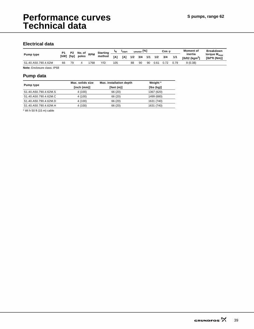
S1.40.A50.790.4.62M 66 79 4 1768 Y/D 105 88 90 90 0.61 0.72 0.79 9 (0.38)
Pump typeMax. solids size Max. installation depth Weight *
[inch (mm)] [feet (m)] [lbs (kg)]S1.40.A50.790.4.62M.S 4 (100) 66 (20) 1367 (620)S1.40.A50.790.4.62M.C 4 (100) 66 (20) 1499 (680)S1.40.A50.790.4.62M.D 4 (100) 66 (20) 1631 (740)S1.40.A50.790.4.62M.H 4 (100) 66 (20) 1631 (740)
39
Performance curves Technical data
S pumps, range 62
40
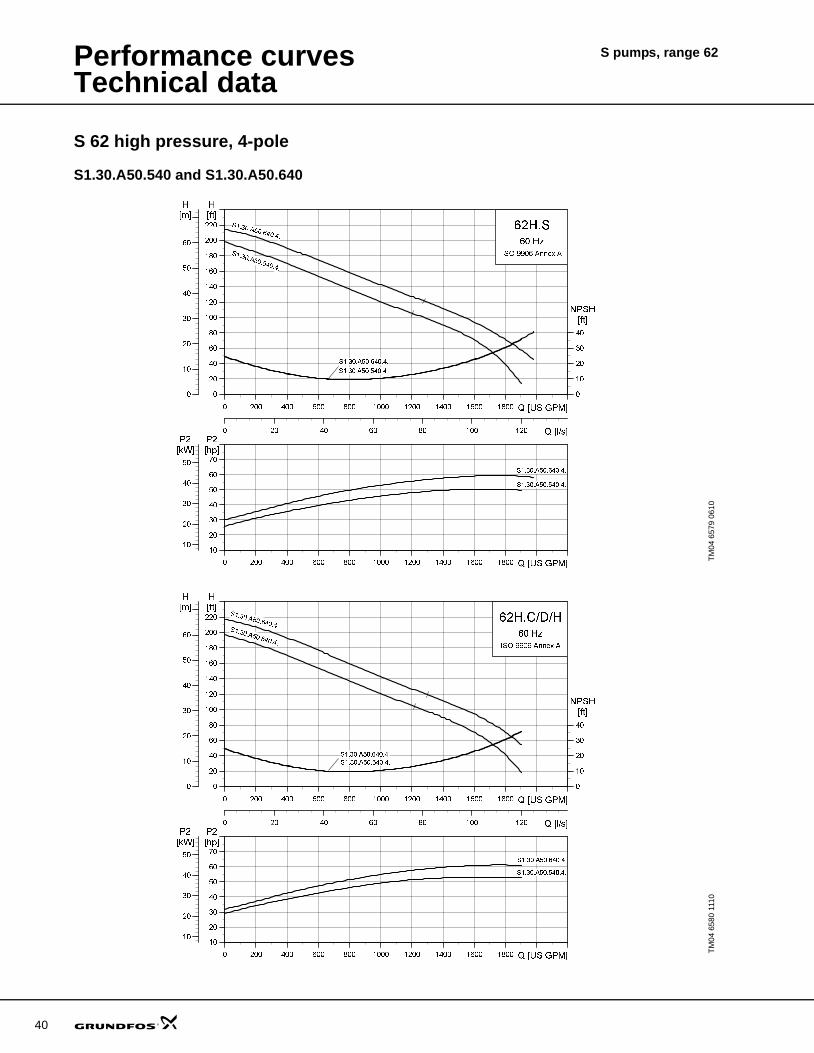
S 62 high pressure, 4-pole
S1.30.A50.540 and S1.30.A50.640
TM04
657
9 06
10TM
04 6
580
1110
0 200 400 600 800 1000 1200 1400 1600 1800 Q [US GPM]
0
20
40
60
80
100
120
140
160
180
200
220
[ft]H
0 20 40 60 80 100 120 Q [l/s]
0
10
20
30
40
50
60
[m]H
0
10
20
30
40
[ft]NPSH
62H.S
60 Hz
ISO 9906 Annex A
S1.30.A50.540.4.
S1.30.A50.640.4.
S1.30.A50.540.4.
S1.30.A50.640.4.
0 200 400 600 800 1000 1200 1400 1600 1800 Q [US GPM]
10
20
30
40
50
60
70
[hp]
P2
10
20
30
40
50
[kW]
P2
S1.30.A50.540.4.
S1.30.A50.640.4.
0 200 400 600 800 1000 1200 1400 1600 1800 Q [US GPM]
0
20
40
60
80
100
120
140
160
180
200
220
[ft]H
0 20 40 60 80 100 120 Q [l/s]
0
10
20
30
40
50
60
[m]H
0
10
20
30
40
[ft]NPSH
62H.C/D/H
60 Hz
ISO 9906 Annex A
S1.30.A50.540.4.
S1.30.A50.640.4.
S1.30.A50.540.4.
S1.30.A50.640.4.
0 200 400 600 800 1000 1200 1400 1600 1800 Q [US GPM]
10
20
30
40
50
60
70
[hp]
P2
10
20
30
40
50
[kW]
P2
S1.30.A50.540.4.
S1.30.A50.640.4.

Performance curves Technical data
S pumps, range 62
Electrical data
Note: Enclosure class: IP68
Pump data
* Wi h 50 ft (15 m) cable
Pump type P1 [kW]
P2 [hp]
No. of poles RPM Starting
method
IN Istart ηmotor [%] Cos φ Moment of inertia
[lbft2 (kgm2]
Breakdown torque Mmax [lbf*ft (Nm)][A] [A] 1/2 3/4 1/1 1/2 3/4 1/1
S1.30.A50.540.4.62H. 44 54 4 1770 Y/D 73 571 87 89 90 0.60 0.70 0.77 7.12 (0.3) 438.8 (595)S1.30.A50.640.4.62H 53 64 4 1764 Y/D 85 571 88 90 90 0.65 0.75 0.79 7.12 (0.3) 438.8 (595)
Pump typeMax. solids size Max. installation depth Weight *
[inch (mm)] [feet (m)] [lbs (kg)]S1.30.A50.540.4.62H.S 3 (80) 66 (20) 1323 (600)S1.30.A50.540.4.62H.C 3 (80) 66 (20) 1455 (660)S1.30.A50.540.4.62H.D 3 (80) 66 (20) 1587 (720)S1.30.A50.540.4.62H.H 3 (80) 66 (20) 1698 (770)S1.30.A50.640.4.62H.S 3 (80) 66 (20) 1323 (600)S1.30.A50.640.4.62H.C 3 (80) 66 (20) 1455 (660)S1.30.A50.640.4.62H.D 3 (80) 66 (20) 1587 (720)S1.30.A50.640.4.62H.H 3 (80) 66 (20) 1587 (720)
41

Performance curves Technical data
S pumps, range 62
42
S 62 high pressure, 4 pole
S1.30.A50.790
TM04
683
9 06
10TM
04 6
923
1110
0 200 400 600 800 1000 1200 1400 1600 1800 Q [US GPM]
0
40
80
120
160
200
240
[ft]H
0 20 40 60 80 100 120 Q [l/s]
0
20
40
60
[m]H
0
10
20
30
40
[ft]NPSH
62H.S
60 Hz
ISO 9906 Annex A
S1.30.A50.790.4.
S1.30.A50.790.4.
0 200 400 600 800 1000 1200 1400 1600 1800 Q [US GPM]
30
40
50
60
70
80
[hp]
P2
30
40
50
60
[kW]
P2
S1.30.A50.790.4.
0 200 400 600 800 1000 1200 1400 1600 1800 Q [US GPM]
0
40
80
120
160
200
240
[ft]H
0 20 40 60 80 100 120 Q [l/s]
0
20
40
60
[m]H
0
10
20
30
40
[ft]NPSH
62H.C/D/H
60 Hz
ISO 9906 Annex A
S1.30.A50.790.4.
S1.30.A50.790.4.
0 200 400 600 800 1000 1200 1400 1600 1800 Q [US GPM]
30
40
50
60
70
80
[hp]
P2
30
40
50
60
[kW]
P2
S1.30.A50.790.4.

Performance curves Technical data
S pumps, range 62
Electrical data
Note: Enclosure class: IP68
Pump data
* Wi h 50 ft (15 m) cable
Pump type P1 [kW]
P2 [hp]
No. of poles RPM Starting
method
IN Istart ηmotor [%] Cos φ Moment of inertia
[lbft2 (kgm2]
Breakdown torque Mmax [lbf*ft (Nm)][A] [A] 1/2 3/4 1/1 1/2 3/4 1/1
S1.30.A50.790.4.62H 66 79 4 1768 Y/D 105 88 90 90 0.61 0.72 0.79 9 (0.38)
Pump typeMax. solids size Max. installation depth Weight *
[inch (mm)] [feet (m)] [lbs (kg)]S1.30.A50.790.4.62H.S 3 (80) 66 (20) 1367 (620)S1.30.A50.790.4.62H.C 3 (80) 66 (20) 1499 (680)S1.30.A50.790.4.62H.D 3 (80) 66 (20) 1631 (740)S1.30.A50.790.4.62H.H 3 (80) 66 (20) 1631 (740)
43

44
S pumps, range 62Accessories
Accessories (for installation)
* Installation type S and C pumps with discharge flange size NPS 10" (DN 250) and higher are supplied with guide claw mounted on the flange.
Pump type Installation accessoriesS 50-70 S and C NPS 3-8 (DN 80-200) without guide claw (guide claw included in auto-coupling kit)S 50-70 S and C NPS 10-24 (DN 250-600) with guide claw mounted on the pumpS 50-70 D Pump without installation accessories (accessories as separate kit)S 50-70 H Base stand for horizontal, dry installation supplied together with the pump
Pictures Description Size Weight[kg] PN Product
number
Gr8
126
Cast-iron, epoxy-coated auto-coupling system complete with:• guide claw *• base unit• upper guide rail bracket• gaskets and bolts.
Dis
char
ge fl
ange NPS 8"
(DN 200)551(250 10 97506541
NPS 5"/NPS 6"(DN 125/150)
229.28 (104) 10 97626242
Intermediate guide rail bracket For guide rails longer than 19.5 feet (6 m)
NPS 5"/NPS 6"(DN 125/150) 3 96829331
NPS 8"/NPS 24"(DN 200/DN 600) 8 96255842
Guide rails Standard pipes. Not supplied by Grundfos
TM04
403
5 05
09
Vertical base stand (without bend).Su
ctio
n fla
nge
NPS 6"(DN150) 96308238
NPS 8"(DN 200) 96094523
NPS 10"(DN 250) 96856263
TM04
415
6 09
09
Galvanised steel base stand for horizontal, dry installa-tion.Supplied with bolts, gaskets and anchor bolts.
NPS 6"(DN150) 96787496
NPS 8"(DN 200) 96787497
NPS 10"(DN 250) 96857521

Accessories S pumps, range 62
Other accessories
Pictures Description Dimensions Product number
TM02
612
6 51
0213 ft (4 m) galvanised lifting chain with lifting link and safety hook.With certificates.
7054.8 lbs(3200 kg) S 62-72
96468294
20 ft (6 m) galvanised lifting chain with lifting link and safety hook.With certificates. 96468295
26 ft (8 m) galvanised lifting chain with lifting link and safety hook.With certificates. 96468296
33 ft (10 m) galvanised lifting chain with lifting link and safety hook. With certificates. 96468297
40 ft (12 m) galvanised lifting chain with lifting link and safety hook.With certificates. 96468298
13 ft (4 m) stainless steel lifting chain with lifting link and safety hook.With certificates.
7054.8 lbs(3200 kg) S 62-72
96490259
20 ft (6 m) stainless steel lifting chain with lifting link and safety hook. With certificates. 96490270
26 ft (8 m) stainless steel lifting chain with lifting link and safety hook. With certificates. 96490271
33 ft (10 m) stainless steel lifting chain with lifting link and safety hook.With certificates. 96490272
40 ft (12 m) stainless steel lifting chain with lifting link and safety hook. With certificates. 96490273
TM01
698
2 39
99
Float switch with 33 ft (10 m) cable 96003332
Float switch with 66 ft (20 m) cable 96003695
TM02
886
2 09
04
Bracket for two float switches 96003338
TM02
067
0 50
00
Float switches with bracket, 33 ft (10 m) cable
2 switches, 1 pump without alarm 62500013
3 switches, 1 pump with alarm 62500014
3 switches, 2 pumps with alarm 62500014
4 switches, 2 pumps with alarm 62500015
45

46
S pumps, range 62Dimensions
Installation on auto coupling
Fig.
16
Dim
ensi
onal
ske
tche
s, in
stal
latio
n on
aut
o-co
uplin
g sy
stem
Z12a
is m
inim
um re
com
men
ded
dist
ance
from
pit
botto
m to
bot
tom
of p
ump
suct
ion
side
.
Z11
is to
tal h
eigh
t of p
ump
inst
alle
d on
Gru
ndfo
s in
stal
latio
n ac
cess
ory
in th
e pi
t. N
OTE
: Thi
s fig
ure
mig
ht n
ot e
qual
Z12
a +
Z1.
Not
e:
TM04 2417 2508
Z14
Z17
G/S
Min
. lev
el,
nsta
llatio
n S
Min
. lev
el,
nsta
llatio
n C

Dimensions S pumps, range 62
S pu
mps
, ran
ge 6
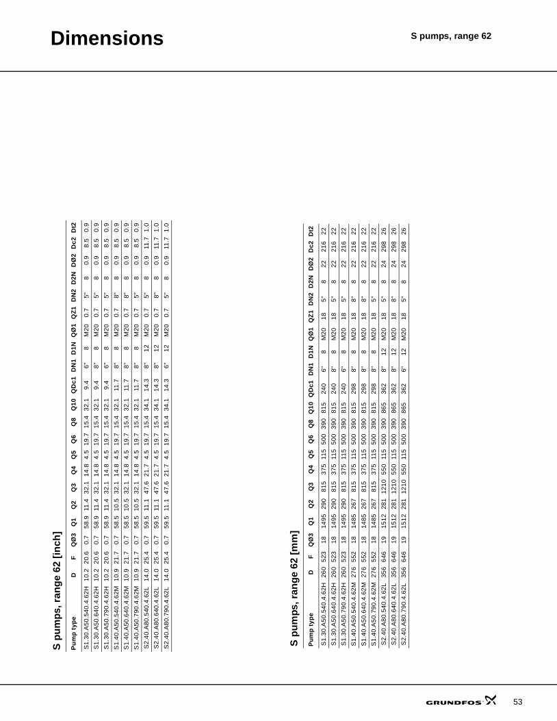
2 [in
ch]
ZM
4XM
164X
M16
4XM
164X
M16
4XM
164X
M16
ZL2
5.8
5.8
5.8
5.8
5.8
5.8
ZL1
22.5
22.5
22.5
22.5
22.5
22.5
ZDt1
1.0
1.0
1.0
1.0
1.0
1.0
ZDN
1
6" 6" 6" 6" 6" 6"
ZDc1
9.4
9.4
9.4
9.4
9.4
9.4
Z17 S 0.
10.
10.
10.
10.
10.
1
G 0.1
0.1
0.1
0.1
0.1
0.1
Z16
22.6
22.6
22.6
22.6
22.6
22.6
Z15
11.0
11.0
11.0
11.0
11.0
11.0
Z14 - - - - - -
Z13 - - - - - -
Z12b
15.7
15.7
15.7
15.7
15.7
15.7
Z12a
3.1
3.9
3.1
3.9
3.9
3.1
Z11
63.2
63.7
63.2
63.7
63.7
63.2
Z10
3.5
3.5
3.5
3.5
3.5
3.5
Z9 4.3
4.3
4.3
4.3
4.3
4.3
Z8 27.4
27.4
27.4
27.4
27.4
27.4
Z7 37.3
37.3
37.3
37.3
37.3
37.3
Z6 49.6
49.6
49.6
49.6
49.6
49.6
Z4 11.0
11.0
11.0
11.0
11.0
11.0
Z3 4.8
4.8
4.8
4.8
4.8
4.8
Z2 11.8
11.8
11.8
11.8
11.8
11.8
Z1 56.5
57.6
56.5
57.6
57.6
56.5
ZØ1
8X23
8X23
8X23
8X23
8X23
8X23
F
20.6
21.7
20.6
21.7
21.7
20.6
C 27.2
27.2
27.2
27.2
27.2
27.2
Pum
p ty
pe
S1.
30.A
50.5
40.4
.62H
S1.
40.A
50.5
40.4
.62M
S1.
30.A
50.6
40.4
.62H
S1.
40.A
50.6
40.4
.62M
S1.
40.A
50.7
90.4
.62M
S1.
30.A
50.7
90.4
.62H
S pu
mps
, ran
ge 6
2 [m
m]
ZM
4 X
M16
4 X
M16
4 X
M16
4 X
M16
4 X
M16
4 X
M16
ZL2
147
147
147
147
147
147
ZL1
571
571
571
571
571
571
ZDt1
25 25 25 25 25 25
ZDN
1
6" 6" 6" 6" 6" 6"
ZDc1
240
240
240
240
240
240
Z17 S 3.
03.
03.
03.
03.
03.
0
G 3.0
3.0
3.0
3.0
3.0
3.0
Z16
575
575
575
575
575
575
Z15
280
280
280
280
280
280
Z14 - - - - - -
Z13 - - - - - -
Z12b
400
400
400
400
400
400
Z12a 80 100
80 100
100
80
Z11
1605
1618
1605
1618
1618
1605
Z10
88.0
88.0
88.0
88.0
88.0
88.0
Z9 110
110
110
110
110
110
Z8 697
697
697
697
697
697
Z7 947
947
947
947
947
947
Z6 1261
1261
1261
1261
1261
1261
Z4 280
280
280
280
280
280
Z3 123
123
123
123
123
123
Z2 300
300
300
300
300
300
Z1 1435
1463
1435
1463
1463
1435
ZØ1
8X23
8X23
8X23
8X23
8X23
8X23
F 523
552
523
552
552
523
C 690
690
690
690
690
690
Pum
p ty
pe
S1.
30.A
50.5
40.4
.62H
S1.
40.A
50.5
40.4
.62M
S1.
30.A
50.6
40.4
.62H
S1.
40.A
50.6
40.4
.62M
S1.
40.A
50.7
90.4
.62M
S1.
30.A
50.7
90.4
.62H
47

Dimensions S pumps, range 62
48
Fig.
17
Dim
ensi
onal
ske
tche
s, in
stal
latio
n on
aut
o-co
uplin
g sy
stem
(2)
Z12a
is m
inim
um re
com
men
ded
dist
ance
from
pit
botto
m to
bot
tom
of p
ump
suct
ion
side
.
Z11
is to
tal h
eigh
t of p
ump
inst
alle
d on
Gru
ndfo
s in
stal
latio
n ac
cess
ory
in th
e pi
t. N
OTE
: Thi
s fig
ure
mig
ht n
ot e
qual
Z12
a +
Z1.
Not
e:
TM04 2417 2508
Z14

Dimensions S pumps, range 62
S pu
mps
, ran
ge 6
2 [in
ch]
ZM
4XM
244X
M24
4XM
24
ZL2
8.7
8.7
8.7
ZL1
30.0
30.0
30.0
ZDt1
1.2
1.2
1.2
ZDN
1
8" 8" 8"
ZDc1
11.6
11.6
11.6
Z17 S 0.
10.
10.
1
G 0.1
0.1
0.1
Z16
19.1
19.1
19.1
Z15
14.4
14.4
14.4
Z14
3.4
3.4
3.4
Z13
7.9
7.9
7.9
Z12b
7.7
7.7
7.7
Z12a
6.1
6.1
6.1
Z11
64.1
64.1
64.1
Z10
3.5
3.5
3.5
Z9 6.7
6.7
6.7
Z8 41.4
41.4
41.4
Z7 53.2
53.2
53.2
Z6 67.8
67.8
67.8
Z4 21.1
21.1
21.1
Z3 7.9
7.9
7.9
Z2 16.9
16.9
16.9
Z1 57.9
57.9
57.9
ZØ1
8X23
8X23
8X23
F
25.4
25.4
25.4
C 37.8
37.8
37.8
Pum
p ty
pe
S2.
40.A
80.5
40.4
.62L
S2.
40.A
80.6
40.4
.62L
S2.
40.A
80.7
90.4
.62L
S pu
mps
, ran
ge 6
2 [m
m]
ZM
4 X
M24
4 X
M24
4 X
M24
ZL2
222
222
222
ZL1
761
761
761
ZDt1
31 31 31
ZDN
1
8" 8" 8"
ZDc1
295
295
295
Z17 3.
03.
03.
0
3.0
3.0
3.0
Z16
485
485
485
Z15
365
365
365
Z14
86 86 86
Z13
200
200
200
Z12b
196
196
196
Z12a
156
156
156
Z11
1627
1627
1627
Z10
88.0
88.0
88.0
Z9 170
170
170
Z8 1052
1052
1052
Z7 1352
1352
1352
Z6 1721
1721
1721
Z4 535
535
535
Z3 200
200
200
Z2 430
430
430
Z1 1471
1471
1471
ZØ1
8X23
8X23
8X23
F 646
646
646
C 960
960
960
Pum
p ty
pe
S2.
40.A
80.5
40.4
.62L
S2.
40.A
80.6
40.4
.62L
S2.
40.A
80.7
90.4
.62L
49

Dimensions S pumps, range 62
50
Dry, vertical installation
Fig.
18
Dim
ensi
onal
ske
tch,
dry
, ver
tical
inst
alla
tion
TM04 2422 2508
X13
X13
1

Dimensions S pumps, range 62
S pu
mps
, ran
ge 6
2 [in
ch]
XM1
M20
X6
M20
X6
M20
X6
M24
X6
M24
X6
M20
X6
M20
X6
M24
X6
M20
X6
Dt2 0.9
0.9
0.9
1.0
1.0
0.9
0.9
1.0
0.9
XDt1
0.9
1.0
0.9
1.1
1.1
1.0
1.0
1.1
0.9
XDc3
9.4
11.6
9.4
14.3
14.3
11.6
11.6
14.3
9.4
X17
35.2
38.1
35.2
44.1
44.1
38.1
38.1
44.1
35.2
X16
82.6
86.1
82.6
92.6
92.6
86.1
86.1
92.6
82.6
X15
20.5
23.9
20.5
27.2
27.2
23.9
23.9
27.2
20.5
X14
11.4
10.4
11.4
18.1
18.1
10.4
10.4
18.1
11.4
X132
4.7
4.7
4.7
5.9
5.9
4.7
4.7
5.9
4.7
X131
5.9
6.9
5.9
7.9
7.9
6.9
6.9
7.9
5.9
X13
17.7
20.7
17.7
23.6
23.6
20.7
20.7
23.6
17.7
X10
6" 8" 6" 8" 8" 8" 8" 8" 6"
X6 24.4
28.3
24.4
33.7
33.7
28.3
28.3
33.7
24.4
X5 11.7
13.5
11.7
16.7
16.7
13.5
13.5
16.7
11.7
X4 11.8
13.8
11.8
15.7
15.7
13.8
13.8
15.7
11.8
XØ5
0.9
0.9
0.9
1.1
1.1
0.9
0.9
1.1
0.9
XØ3
0.9
0.9
0.9
0.9
0.9
0.9
0.9
0.9
0.9
F
20.6
21.7
20.6
25.4
25.4
21.7
21.7
25.4
20.6
C 27.2
27.2
27.2
37.8
37.8
27.2
27.2
37.8
27.2
Pum
p ty
pe
S1.
30.A
50.5
40.4
.62H
S1.
40.A
50.5
40.4
.62M
S1.
30.A
50.6
40.4
.62H
S2.
40.A
80.5
40.4
.62L
S2.
40.A
80.6
40.4
.62L
S1.
40.A
50.6
40.4
.62M
S1.
40.A
50.7
90.4
.62M
S2.
40.A
80.7
90.4
.62L
S1.
30.A
50.7
90.4
.62H
S pu
mps
, ran
ge 6
2 [m
m]
XM1
M20
X6
M20
X6
M20
X6
M24
X6
M24
X6
M20
X6
M20
X6
M24
X6
M20
X6
Dt2 22 22 22 26 26 22 22 26 22
XDt1
24 26 24 28 28 26 26 28 24
XDc3
240
295
240
362
362
295
295
362
240
X17
893
968
893
1120
1120
968
968
1120
893
X16
2098
2186
2098
2351
2351
2186
2186
2351
2098
X15
520
606
520
692
692
606
606
692
520
X14
290
265
290
460
460
265
265
460
290
X132
120
120
120
150
150
120
120
150
120
X131
150
175
150
200
200
175
175
200
150
X13
450
525
450
600
600
525
525
600
450
X10
6" 8" 6" 8" 8" 8" 8" 8" 6"
X6 621
719
621
857
857
719
719
857
621
X5 296
344
296
425
425
344
344
425
296
X4 300
350
300
400
400
350
350
400
300
XØ5
24 24 24 28 28 24 24 28 24
XØ3
24 24 24 24 24 24 24 24 24
F 523
552
523
646
646
552
552
646
523
C 690
690
690
960
960
690
690
960
690
Pum
p ty
pe
S1.
30.A
50.5
40.4
.62H
S1.
40.A
50.5
40.4
.62M
S1.
30.A
50.6
40.4
.62H
S2.
40.A
80.5
40.4
.62L
S2.
40.A
80.6
40.4
.62L
S1.
40.A
50.6
40.4
.62M
S1.
40.A
50.7
90.4
.62M
S2.
40.A
80.7
90.4
.62L
S1.
30.A
50.7
90.4
.62H
51

Dimensions S pumps, range 62
52
Dry, horisontal installation
Fig.
19
Dim
ensi
onal
ske
tch,
dry
, hor
ison
tal i
nsta
llatio
n
TM04 2414 2508
QZ1
Dimensions S pumps, range 62
S pu
mps
, ran
ge 6
2 [in
ch]
Dt2 0.9
0.9
0.9
0.9
0.9
0.9
1.0
1.0
1.0
Dc2 8.5
8.5
8.5
8.5
8.5
8.5
11.7
11.7
11.7
DØ
2
0.9
0.9
0.9
0.9
0.9
0.9
0.9
0.9
0.9
D2N 8 8 8 8 8 8 8 8 8
DN
2
5" 5" 5" 8" 8" 5" 5" 8" 5"
QZ1 0.7
0.7
0.7
0.7
0.7
0.7
0.7
0.7
0.7
QØ
1
M20
M20
M20
M20
M20
M20
M20
M20
M20
D1N 8 8 8 8 8 8 12 12 12
DN
1
6" 8" 6" 8" 8" 8" 8" 8" 6"
QD
c1
9.4
9.4
9.4
11.7
11.7
11.7
14.3
14.3
14.3
Q10
32.1
32.1
32.1
32.1
32.1
32.1
34.1
34.1
34.1
Q8
15.4
15.4
15.4
15.4
15.4
15.4
15.4
15.4
15.4
Q6
19.7
19.7
19.7
19.7
19.7
19.7
19.7
19.7
19.7
Q5
4.5
4.5
4.5
4.5
4.5
4.5
4.5
4.5
4.5
Q4
14.8
14.8
14.8
14.8
14.8
14.8
21.7
21.7
21.7
Q3
32.1
32.1
32.1
32.1
32.1
32.1
47.6
47.6
47.6
Q2
11.4
11.4
11.4
10.5
10.5
10.5
11.1
11.1
11.1
Q1
58.9
58.9
58.9
58.5
58.5
58.5
59.5
59.5
59.5
QØ
3
0.7
0.7
0.7
0.7
0.7
0.7
0.7
0.7
0.7
F
20.6
20.6
20.6
21.7
21.7
21.7
25.4
25.4
25.4
D 10.2
10.2
10.2
10.9
10.9
10.9
14.0
14.0
14.0
Pum
p ty
pe
S1.
30.A
50.5
40.4
.62H
S1.
30.A
50.6
40.4
.62H
S1.
30.A
50.7
90.4
.62H
S1.
40.A
50.5
40.4
.62M
S1.
40.A
50.6
40.4
.62M
S1.
40.A
50.7
90.4
.62M
S2.
40.A
80.5
40.4
.62L
S2.
40.A
80.6
40.4
.62L
S2.
40.A
80.7
90.4
.62L
S pu
mps
, ran
ge 6
2 [m
m]
Dt2 22 22 22 22 22 22 26 26 26
Dc2 216
216
216
216
216
216
298
298
298
DØ
2
22 22 22 22 22 22 24 24 24
D2N 8 8 8 8 8 8 8 8 8
DN
2
5" 5" 5" 8" 8" 5" 5" 8" 5"
QZ1 18 18 18 18 18 18 18 18 18
QØ
1
M20
M20
M20
M20
M20
M20
M20
M20
M20
D1N 8 8 8 8 8 8 12 12 12
DN
1
6" 8" 6" 8" 8" 8" 8" 8" 6"
QD
c1
240
240
240
298
298
298
362
362
362
Q10
815
815
815
815
815
815
865
865
865
Q8
390
390
390
390
390
390
390
390
390
Q6
500
500
500
500
500
500
500
500
500
Q5
115
115
115
115
115
115
115
115
115
Q4
375
375
375
375
375
375
550
550
550
Q3
815
815
815
815
815
815
1210
1210
1210
Q2
290
290
290
267
267
267
281
281
281
Q1
1495
1495
1495
1485
1485
1485
1512
1512
1512
QØ
3
18 18 18 18 18 18 19 19 19
F 523
523
523
552
552
552
646
646
646
D 260
260
260
276
276
276
356
356
356
Pum
p ty
pe
S1.
30.A
50.5
40.4
.62H
S1.
30.A
50.6
40.4
.62H
S1.
30.A
50.7
90.4
.62H
S1.
40.A
50.5
40.4
.62M
S1.
40.A
50.6
40.4
.62M
S1.
40.A
50.7
90.4
.62M
S2.
40.A
80.5
40.4
.62L
S2.
40.A
80.6
40.4
.62L
S2.
40.A
80.7
90.4
.62L
53

54
S pumps, range 62Further product documentation
WebCAPSWebCAPS is a Web-based Computer Aided Product Selection program available on www.grundfos.com.
WebCAPS contains detailed information on more than 185,000 Grundfos products in more than 20 languages.
In WebCAPS, all information is divided into 6 sections:
• Catalogue• Literature• Service• Sizing• Replacement• CAD drawings.
Catalogue
This section is based on fields of application and pump types, and contains • technical data• curves (QH, Eta, P1, P2, etc) which can be adapted to the den-
sity and viscosity of the pumped liquid and show the number of pumps in operation
• product photos• dimensional drawings• wiring diagrams• quotation texts, etc.
Literature
In this section you can access all the latest documents of a given pump, such as• data booklets• installation and operating instructions• service documentation, such as Service kit catalogue and
Service kit instructions• quick guides• product brochures, etc.
Service
This section contains an easy-to-use interactive service cata-logue. Here you can find and identify service parts of both existing and discontinued Grundfos pumps.Furthermore, this section contains service videos showing you how to replace service parts.

Further product documentation
S pumps, range 62
WinCAPS
Fig. 20 WinCAPS CD-ROM
WinCAPS is a Windows-based Computer Aided Prod-uct Selection program containing detailed information on more than 185,000 Grundfos products in more than 20 languages.
The program contains the same features and functions as WebCAPS, but is an ideal solution if no Internet con-nection is available.
WinCAPS is available on CD-ROM and updated once a year.
Sizing
This section is based on different fields of application and installa-tion examples, and gives easy step-by-step instructions in how to• select the most suitable and efficient pump for your installation• carry out advanced calculations based on energy consumption,
payback periods, load profiles, life cycle costs, etc.• analyse your selected pump via the built-in life cycle cost tool• determine the flow velocity in wastewater applications, etc.
Replacement
In this section you find a guide to selecting and comparing re-placement data of an installed pump in order to replace the pump with a more efficient Grundfos pump. The section contains replacement data of a wide range of pumps produced by other manufacturers than Grundfos.
Based on an easy step-by-step guide, you can compare Grund-fos pumps with the one you have installed on your site. When you have specified the installed pump, the guide will suggest a number of Grundfos pumps which can improve both comfort and efficiency.
CAD drawings
In this section it is possible to download 2-dimensional (2D) and 3-dimensional (3D) CAD drawings of most Grundfos pumps.
These formats are available in WebCAPS:
2-dimensional drawings:• .dxf, wireframe drawings• .dwg, wireframe drawings.
3-dimensional drawings:• .dwg, wireframe drawings (without surfaces)• .stp, solid drawings (with surfaces)• .eprt, E-drawings.
0 1
Subject to alterations.
55