Embed Size (px)
Citation preview
Advanced Design System 2011.01 - S-Parameter Simulation
1
Advanced Design System 2011.01
Feburary 2011S-Parameter Simulation
Advanced Design System 2011.01 - S-Parameter Simulation
2
© Agilent Technologies, Inc. 2000-20115301 Stevens Creek Blvd., Santa Clara, CA 95052 USANo part of this documentation may be reproduced in any form or by any means (includingelectronic storage and retrieval or translation into a foreign language) without prioragreement and written consent from Agilent Technologies, Inc. as governed by UnitedStates and international copyright laws.
AcknowledgmentsMentor Graphics is a trademark of Mentor Graphics Corporation in the U.S. and othercountries. Mentor products and processes are registered trademarks of Mentor GraphicsCorporation. * Calibre is a trademark of Mentor Graphics Corporation in the US and othercountries. "Microsoft®, Windows®, MS Windows®, Windows NT®, Windows 2000® andWindows Internet Explorer® are U.S. registered trademarks of Microsoft Corporation.Pentium® is a U.S. registered trademark of Intel Corporation. PostScript® and Acrobat®are trademarks of Adobe Systems Incorporated. UNIX® is a registered trademark of theOpen Group. Oracle and Java and registered trademarks of Oracle and/or its affiliates.Other names may be trademarks of their respective owners. SystemC® is a registeredtrademark of Open SystemC Initiative, Inc. in the United States and other countries and isused with permission. MATLAB® is a U.S. registered trademark of The Math Works, Inc..HiSIM2 source code, and all copyrights, trade secrets or other intellectual property rightsin and to the source code in its entirety, is owned by Hiroshima University and STARC.FLEXlm is a trademark of Globetrotter Software, Incorporated. Layout Boolean Engine byKlaas Holwerda, v1.7 http://www.xs4all.nl/~kholwerd/bool.html . FreeType Project,Copyright (c) 1996-1999 by David Turner, Robert Wilhelm, and Werner Lemberg.QuestAgent search engine (c) 2000-2002, JObjects. Motif is a trademark of the OpenSoftware Foundation. Netscape is a trademark of Netscape Communications Corporation.Netscape Portable Runtime (NSPR), Copyright (c) 1998-2003 The Mozilla Organization. Acopy of the Mozilla Public License is at http://www.mozilla.org/MPL/ . FFTW, The FastestFourier Transform in the West, Copyright (c) 1997-1999 Massachusetts Institute ofTechnology. All rights reserved.
The following third-party libraries are used by the NlogN Momentum solver:
"This program includes Metis 4.0, Copyright © 1998, Regents of the University ofMinnesota", http://www.cs.umn.edu/~metis , METIS was written by George Karypis([email protected]).
Intel@ Math Kernel Library, http://www.intel.com/software/products/mkl
SuperLU_MT version 2.0 - Copyright © 2003, The Regents of the University of California,through Lawrence Berkeley National Laboratory (subject to receipt of any requiredapprovals from U.S. Dept. of Energy). All rights reserved. SuperLU Disclaimer: THISSOFTWARE IS PROVIDED BY THE COPYRIGHT HOLDERS AND CONTRIBUTORS "AS IS"AND ANY EXPRESS OR IMPLIED WARRANTIES, INCLUDING, BUT NOT LIMITED TO, THEIMPLIED WARRANTIES OF MERCHANTABILITY AND FITNESS FOR A PARTICULAR PURPOSEARE DISCLAIMED. IN NO EVENT SHALL THE COPYRIGHT OWNER OR CONTRIBUTORS BELIABLE FOR ANY DIRECT, INDIRECT, INCIDENTAL, SPECIAL, EXEMPLARY, ORCONSEQUENTIAL DAMAGES (INCLUDING, BUT NOT LIMITED TO, PROCUREMENT OF
Advanced Design System 2011.01 - S-Parameter Simulation
3
SUBSTITUTE GOODS OR SERVICES; LOSS OF USE, DATA, OR PROFITS; OR BUSINESSINTERRUPTION) HOWEVER CAUSED AND ON ANY THEORY OF LIABILITY, WHETHER INCONTRACT, STRICT LIABILITY, OR TORT (INCLUDING NEGLIGENCE OR OTHERWISE)ARISING IN ANY WAY OUT OF THE USE OF THIS SOFTWARE, EVEN IF ADVISED OF THEPOSSIBILITY OF SUCH DAMAGE.
7-zip - 7-Zip Copyright: Copyright (C) 1999-2009 Igor Pavlov. Licenses for files are:7z.dll: GNU LGPL + unRAR restriction, All other files: GNU LGPL. 7-zip License: This libraryis free software; you can redistribute it and/or modify it under the terms of the GNULesser General Public License as published by the Free Software Foundation; eitherversion 2.1 of the License, or (at your option) any later version. This library is distributedin the hope that it will be useful,but WITHOUT ANY WARRANTY; without even the impliedwarranty of MERCHANTABILITY or FITNESS FOR A PARTICULAR PURPOSE. See the GNULesser General Public License for more details. You should have received a copy of theGNU Lesser General Public License along with this library; if not, write to the FreeSoftware Foundation, Inc., 59 Temple Place, Suite 330, Boston, MA 02111-1307 USA.unRAR copyright: The decompression engine for RAR archives was developed using sourcecode of unRAR program.All copyrights to original unRAR code are owned by AlexanderRoshal. unRAR License: The unRAR sources cannot be used to re-create the RARcompression algorithm, which is proprietary. Distribution of modified unRAR sources inseparate form or as a part of other software is permitted, provided that it is clearly statedin the documentation and source comments that the code may not be used to develop aRAR (WinRAR) compatible archiver. 7-zip Availability: http://www.7-zip.org/
AMD Version 2.2 - AMD Notice: The AMD code was modified. Used by permission. AMDcopyright: AMD Version 2.2, Copyright © 2007 by Timothy A. Davis, Patrick R. Amestoy,and Iain S. Duff. All Rights Reserved. AMD License: Your use or distribution of AMD or anymodified version of AMD implies that you agree to this License. This library is freesoftware; you can redistribute it and/or modify it under the terms of the GNU LesserGeneral Public License as published by the Free Software Foundation; either version 2.1 ofthe License, or (at your option) any later version. This library is distributed in the hopethat it will be useful, but WITHOUT ANY WARRANTY; without even the implied warranty ofMERCHANTABILITY or FITNESS FOR A PARTICULAR PURPOSE. See the GNU LesserGeneral Public License for more details. You should have received a copy of the GNULesser General Public License along with this library; if not, write to the Free SoftwareFoundation, Inc., 51 Franklin St, Fifth Floor, Boston, MA 02110-1301 USA Permission ishereby granted to use or copy this program under the terms of the GNU LGPL, providedthat the Copyright, this License, and the Availability of the original version is retained onall copies.User documentation of any code that uses this code or any modified version ofthis code must cite the Copyright, this License, the Availability note, and "Used bypermission." Permission to modify the code and to distribute modified code is granted,provided the Copyright, this License, and the Availability note are retained, and a noticethat the code was modified is included. AMD Availability:http://www.cise.ufl.edu/research/sparse/amd
UMFPACK 5.0.2 - UMFPACK Notice: The UMFPACK code was modified. Used by permission.UMFPACK Copyright: UMFPACK Copyright © 1995-2006 by Timothy A. Davis. All RightsReserved. UMFPACK License: Your use or distribution of UMFPACK or any modified versionof UMFPACK implies that you agree to this License. This library is free software; you canredistribute it and/or modify it under the terms of the GNU Lesser General Public License
Advanced Design System 2011.01 - S-Parameter Simulation
4
as published by the Free Software Foundation; either version 2.1 of the License, or (atyour option) any later version. This library is distributed in the hope that it will be useful,but WITHOUT ANY WARRANTY; without even the implied warranty of MERCHANTABILITYor FITNESS FOR A PARTICULAR PURPOSE. See the GNU Lesser General Public License formore details. You should have received a copy of the GNU Lesser General Public Licensealong with this library; if not, write to the Free Software Foundation, Inc., 51 Franklin St,Fifth Floor, Boston, MA 02110-1301 USA Permission is hereby granted to use or copy thisprogram under the terms of the GNU LGPL, provided that the Copyright, this License, andthe Availability of the original version is retained on all copies. User documentation of anycode that uses this code or any modified version of this code must cite the Copyright, thisLicense, the Availability note, and "Used by permission." Permission to modify the codeand to distribute modified code is granted, provided the Copyright, this License, and theAvailability note are retained, and a notice that the code was modified is included.UMFPACK Availability: http://www.cise.ufl.edu/research/sparse/umfpack UMFPACK(including versions 2.2.1 and earlier, in FORTRAN) is available athttp://www.cise.ufl.edu/research/sparse . MA38 is available in the Harwell SubroutineLibrary. This version of UMFPACK includes a modified form of COLAMD Version 2.0,originally released on Jan. 31, 2000, also available athttp://www.cise.ufl.edu/research/sparse . COLAMD V2.0 is also incorporated as a built-infunction in MATLAB version 6.1, by The MathWorks, Inc. http://www.mathworks.com .COLAMD V1.0 appears as a column-preordering in SuperLU (SuperLU is available athttp://www.netlib.org ). UMFPACK v4.0 is a built-in routine in MATLAB 6.5. UMFPACK v4.3is a built-in routine in MATLAB 7.1.
Qt Version 4.6.3 - Qt Notice: The Qt code was modified. Used by permission. Qt copyright:Qt Version 4.6.3, Copyright (c) 2010 by Nokia Corporation. All Rights Reserved. QtLicense: Your use or distribution of Qt or any modified version of Qt implies that you agreeto this License. This library is free software; you can redistribute it and/or modify it undertheterms of the GNU Lesser General Public License as published by the Free SoftwareFoundation; either version 2.1 of the License, or (at your option) any later version. Thislibrary is distributed in the hope that it will be useful,but WITHOUT ANY WARRANTY; without even the implied warranty of MERCHANTABILITYor FITNESS FOR A PARTICULAR PURPOSE. See the GNU Lesser General Public License formore details. You should have received a copy of the GNU Lesser General Public Licensealong with this library; if not, write to the Free Software Foundation, Inc., 51 Franklin St,Fifth Floor, Boston, MA 02110-1301 USA Permission is hereby granted to use or copy thisprogram under the terms of the GNU LGPL, provided that the Copyright, this License, andthe Availability of the original version is retained on all copies.Userdocumentation of any code that uses this code or any modified version of this code mustcite the Copyright, this License, the Availability note, and "Used by permission."Permission to modify the code and to distribute modified code is granted, provided theCopyright, this License, and the Availability note are retained, and a notice that the codewas modified is included. Qt Availability: http://www.qtsoftware.com/downloads PatchesApplied to Qt can be found in the installation at:$HPEESOF_DIR/prod/licenses/thirdparty/qt/patches. You may also contact BrianBuchanan at Agilent Inc. at [email protected] for more information.
The HiSIM_HV source code, and all copyrights, trade secrets or other intellectual propertyrights in and to the source code, is owned by Hiroshima University and/or STARC.
Advanced Design System 2011.01 - S-Parameter Simulation
5
Errata The ADS product may contain references to "HP" or "HPEESOF" such as in filenames and directory names. The business entity formerly known as "HP EEsof" is now partof Agilent Technologies and is known as "Agilent EEsof". To avoid broken functionality andto maintain backward compatibility for our customers, we did not change all the namesand labels that contain "HP" or "HPEESOF" references.
Warranty The material contained in this document is provided "as is", and is subject tobeing changed, without notice, in future editions. Further, to the maximum extentpermitted by applicable law, Agilent disclaims all warranties, either express or implied,with regard to this documentation and any information contained herein, including but notlimited to the implied warranties of merchantability and fitness for a particular purpose.Agilent shall not be liable for errors or for incidental or consequential damages inconnection with the furnishing, use, or performance of this document or of anyinformation contained herein. Should Agilent and the user have a separate writtenagreement with warranty terms covering the material in this document that conflict withthese terms, the warranty terms in the separate agreement shall control.
Technology Licenses The hardware and/or software described in this document arefurnished under a license and may be used or copied only in accordance with the terms ofsuch license. Portions of this product include the SystemC software licensed under OpenSource terms, which are available for download at http://systemc.org/ . This software isredistributed by Agilent. The Contributors of the SystemC software provide this software"as is" and offer no warranty of any kind, express or implied, including without limitationwarranties or conditions or title and non-infringement, and implied warranties orconditions merchantability and fitness for a particular purpose. Contributors shall not beliable for any damages of any kind including without limitation direct, indirect, special,incidental and consequential damages, such as lost profits. Any provisions that differ fromthis disclaimer are offered by Agilent only.
Restricted Rights Legend U.S. Government Restricted Rights. Software and technicaldata rights granted to the federal government include only those rights customarilyprovided to end user customers. Agilent provides this customary commercial license inSoftware and technical data pursuant to FAR 12.211 (Technical Data) and 12.212(Computer Software) and, for the Department of Defense, DFARS 252.227-7015(Technical Data - Commercial Items) and DFARS 227.7202-3 (Rights in CommercialComputer Software or Computer Software Documentation).
Advanced Design System 2011.01 - S-Parameter Simulation
6
About S-Parameter Simulation . . . . . . . . . . . . . . . . . . . . . . . . . . . . . . . . . . . . . . . . . . . . . . . 7 Performing an S-Parameter Simulation . . . . . . . . . . . . . . . . . . . . . . . . . . . . . . . . . . . . . . . . . 8 Examples of S-Parameter Simulation . . . . . . . . . . . . . . . . . . . . . . . . . . . . . . . . . . . . . . . . . . 9
Simulating an Amplifier . . . . . . . . . . . . . . . . . . . . . . . . . . . . . . . . . . . . . . . . . . . . . . . . . . 9 Calculating Group Delay . . . . . . . . . . . . . . . . . . . . . . . . . . . . . . . . . . . . . . . . . . . . . . . . . . 10 Simulating Linear Noise . . . . . . . . . . . . . . . . . . . . . . . . . . . . . . . . . . . . . . . . . . . . . . . . . . 11 Analyzing a Frequency Translating Network . . . . . . . . . . . . . . . . . . . . . . . . . . . . . . . . . . . . 12 Eliminating Unwanted Effects . . . . . . . . . . . . . . . . . . . . . . . . . . . . . . . . . . . . . . . . . . . . . . 12
S-Parameter Simulation Description . . . . . . . . . . . . . . . . . . . . . . . . . . . . . . . . . . . . . . . . . . . 14 S-Parameter Definitions . . . . . . . . . . . . . . . . . . . . . . . . . . . . . . . . . . . . . . . . . . . . . . . . . . 14 Group Delay . . . . . . . . . . . . . . . . . . . . . . . . . . . . . . . . . . . . . . . . . . . . . . . . . . . . . . . . . . 15 S-Parameter Frequency Conversion . . . . . . . . . . . . . . . . . . . . . . . . . . . . . . . . . . . . . . . . . . 16
S-Parameter Simulation Noise Analysis . . . . . . . . . . . . . . . . . . . . . . . . . . . . . . . . . . . . . . . . . 18 Noise Figure . . . . . . . . . . . . . . . . . . . . . . . . . . . . . . . . . . . . . . . . . . . . . . . . . . . . . . . . . . 18 Calculating Noise Figure . . . . . . . . . . . . . . . . . . . . . . . . . . . . . . . . . . . . . . . . . . . . . . . . . . 18 Noisy 2-Port Parameters . . . . . . . . . . . . . . . . . . . . . . . . . . . . . . . . . . . . . . . . . . . . . . . . . 19
S-Parameters from Various Input-Output Modes . . . . . . . . . . . . . . . . . . . . . . . . . . . . . . . . . . 21 Improving S-Parameter Simulation Speed . . . . . . . . . . . . . . . . . . . . . . . . . . . . . . . . . . . . . . . 22 Saving Network Parameters into Other Formats . . . . . . . . . . . . . . . . . . . . . . . . . . . . . . . . . . . 23 S-Parameter Simulation Parameters . . . . . . . . . . . . . . . . . . . . . . . . . . . . . . . . . . . . . . . . . . . 24
Setting Frequency Sweep . . . . . . . . . . . . . . . . . . . . . . . . . . . . . . . . . . . . . . . . . . . . . . . . . 24 Defining Simulation Parameters . . . . . . . . . . . . . . . . . . . . . . . . . . . . . . . . . . . . . . . . . . . . 25 Defining Noise Parameters . . . . . . . . . . . . . . . . . . . . . . . . . . . . . . . . . . . . . . . . . . . . . . . . 28
Advanced Design System 2011.01 - S-Parameter Simulation
7
About S-Parameter Simulation Using the S-parameter simulation controller (S-Parameters) from the Simulation-S_Param palette enables you to:
Obtain the scattering parameters (S-parameters) of a component, circuit, orsubnetwork and convert those parameters to Y- or Z-parameters.Plot, for example, the variations in swept-frequency S-parameters with respect toanother changing variable.Simulate group delay or linear noise.Simulate the effects of frequency conversion on small-signal S-parameters in a circuitemploying a mixer. (This is also known as analyzing a frequency-translatingnetwork.)
The Simulation-S_Param palette also contains components for general simulation optionsand sweeps, as well as a variety of measurement components for calculating relevantmeasurements. See the following topics for details on S-parameter simulation:
Performing an S-Parameter Simulation (cktsimsp) has the minimum setuprequirements for an S-parameter simulation.Examples of S-Parameter Simulation (cktsimsp) give detailed setups for running abasic S-parameter simulation on an amplifier, as well as examples for calculatinggroup delay, linear noise, and frequency translation.S-Parameter Simulation Description (cktsimsp) is a brief description of the S-parameter simulator and some of its methods, such as group delay and frequencyconversion.S-Parameter Simulation Noise Analysis (cktsimsp) gives some of the equations andtechniques that are the basis of noise calculations.S-Parameters from Various Input-Output Modes (cktsimsp) describes the featuresavailable in ADS to simulate S-parameters for designs that use various input andoutput modes.Improving S-Parameter Simulation Speed (cktsimsp) describes how theLinearCollapse component can help increase S-parameter simulation speed in ADS.S-Parameter Simulation Parameters (cktsimsp) provides details about the parametersavailable in the S-parameters controller in ADS.
Advanced Design System 2011.01 - S-Parameter Simulation
8
Performing an S-Parameter Simulation Start by creating your design, then add current probes and identify the nodes from whichyou want to collect data.
For a successful analysis, be sure to:
Apply ports to all inputs and outputs. Use P_1Tone or P_nTone power sources todrive inputs. Terminate all other ports using port-impedance terminations (Term).Verify impedance. The Term component is found on the Simulation-S_Param palette.Power sources are on the Sources-Freq Domain palette.Check the Num field for each port. The S-parameter port numbers are derived fromthese fields. For a 2-port circuit, you would want the input labeled as Num=1 and theoutput as Num=2.Add the S-parameter component to the schematic and double-click to edit it. For abasic simulation, fill in the fields under the Frequency tab:
Select the Sweep type, single point, logarithmic, or linear. For a linear orlogarithmic sweep, elect to define the sweep with start/stop or center/spanvalues.
To calculate admittance or impedance parameters, enable the options under theParameters tab.Group delay calculations can be enabled from the Parameters tab.You can enable frequency conversion, which is useful when analyzing circuits withstandard (not user-defined) behavioral mixer models. This option is under theParameters tab.To calculate noise, select the Noise tab and enable Calculate noise . You select a nodefor noise calculations from the Edit list, then click Add. Use the Mode list to sort thenoise contributed by individual noise sources by name or value.
For details about each field, click Help from the dialog box.
For more detailed descriptions of simulation setups, refer to Examples of S-ParameterSimulation (cktsimsp).
Advanced Design System 2011.01 - S-Parameter Simulation
9
Examples of S-Parameter SimulationThis section contains examples for:
Simulating an AmplifierCalculating Group DelaySimulating Linear NoiseAnalyzing a Frequency Translating NetworkEliminating Unwanted Effects
These examples give detailed descriptions for setting up and running S-parametersimulations.
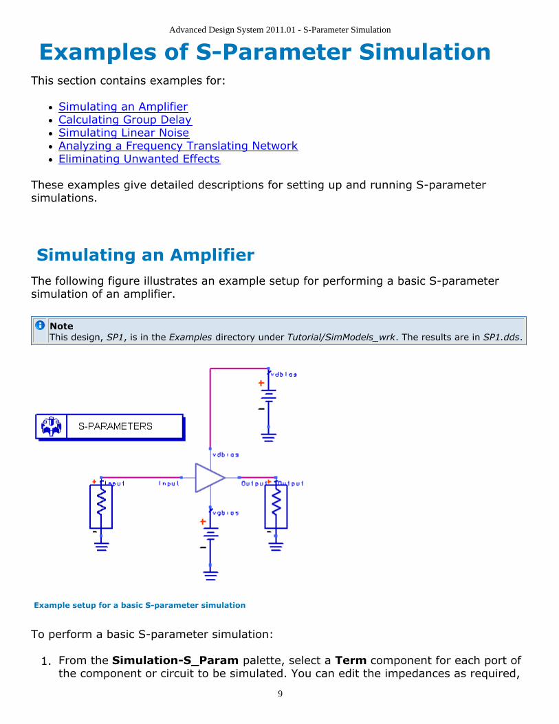
Simulating an AmplifierThe following figure illustrates an example setup for performing a basic S-parametersimulation of an amplifier.
NoteThis design, SP1, is in the Examples directory under Tutorial/SimModels_wrk. The results are in SP1.dds.
Example setup for a basic S-parameter simulation
To perform a basic S-parameter simulation:
From the Simulation-S_Param palette, select a Term component for each port of1.the component or circuit to be simulated. You can edit the impedances as required,
Advanced Design System 2011.01 - S-Parameter Simulation
10
although the default value of 50 ohms is generally sufficient. Ensure that theterminations are properly connected to the component or circuit under test.Ensure that the number of the input Term component is set to Num = 1, and that of2.the output Term component to Num = 2.
Note By default, the Term component provides a noise contribution (Noise = yes), but is inactive unlessnoise contributions are requested. Also, ensure that the number of each Term component (asdefined by the component's Num parameter) is appropriate to the location of the component in thecircuit, to ensure that the S-parameter data is meaningful.
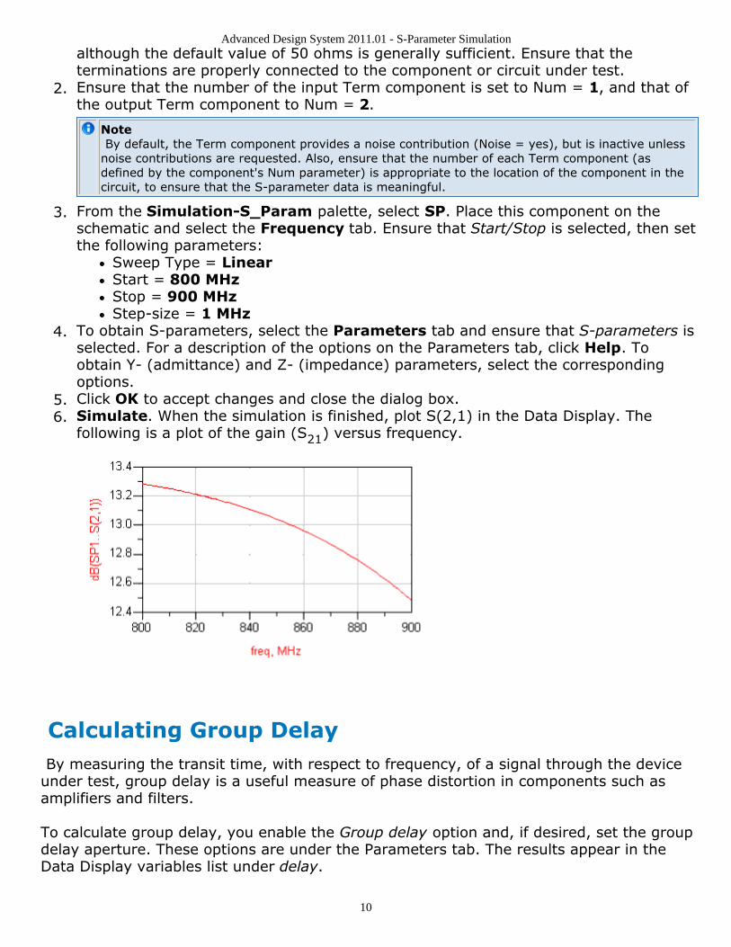
From the Simulation-S_Param palette, select SP. Place this component on the3.schematic and select the Frequency tab. Ensure that Start/Stop is selected, then setthe following parameters:
Sweep Type = LinearStart = 800 MHzStop = 900 MHzStep-size = 1 MHz
To obtain S-parameters, select the Parameters tab and ensure that S-parameters is4.selected. For a description of the options on the Parameters tab, click Help. Toobtain Y- (admittance) and Z- (impedance) parameters, select the correspondingoptions.Click OK to accept changes and close the dialog box.5.Simulate. When the simulation is finished, plot S(2,1) in the Data Display. The6.following is a plot of the gain (S21) versus frequency.
Calculating Group Delay By measuring the transit time, with respect to frequency, of a signal through the deviceunder test, group delay is a useful measure of phase distortion in components such asamplifiers and filters.
To calculate group delay, you enable the Group delay option and, if desired, set the groupdelay aperture. These options are under the Parameters tab. The results appear in theData Display variables list under delay.
Advanced Design System 2011.01 - S-Parameter Simulation
11
For more information, refer to Group Delay (cktsimsp).
To calculate group delay:
Proceed as in Simulating an Amplifier, setting frequencies and sweep parameters as1.needed.Edit the S-Parameters component, select the Parameters tab, and enable Group2.delay.Group delay aperture is an option that is found on network analyzers and behaves3.similarly here. The simulator sets the frequency aperture to 0.01% of the currentfrequency. To override the default frequency aperture, enable Group delayaperture and edit the value as needed.Click OK to accept changes and close the dialog box.4.Simulate. When the simulation is finished, plot the group delay data items, identified5.by the prefix delay. This is the absolute group delay, in seconds.
HintIf the group delay data appears noisy, increase the value in the Group delay aperture field. If theresults appear inaccurate, decrease the value. Generally, adjusting this value by a factor of 10 (inthe appropriate direction) improves noisy or inaccurate results.
For an example of group delay data, see Obtaining Group Delay Data (cktsim).
Simulating Linear NoiseOptions for simulating linear noise are available from the Noise tab of the S-Parameterssimulation component. For more information about how noise is calculated, refer to S-Parameter Simulation Noise Analysis (cktsimsp).
To simulate linear noise:
Proceed as in Simulating an Amplifier, setting frequencies and sweep parameters as1.needed.Edit the S-parameter Simulation component and select the Noise tab. Then select2.the Calculate noise option.In the Edit field, enter the names of the nodes at which you want noise data to be3.reported.
NoteIt is not necessary to name nodes if only noise figure is desired.
Use the Mode popup menu to sort the noise contributors (nodes) that are reported.4.Either accept the default values for Dynamic range to display and Bandwidth, or edit5.these as required. The defaults are generally sufficient.Click OK to accept changes and close the dialog box.6.Simulate. When the simulation is finished, plot the noise data items. These are noise7.figure, identified as nf[ port_number ], and the equivalent input noise temperature,identified as te[ port_number ].
Advanced Design System 2011.01 - S-Parameter Simulation
12
Adjusting Noise Temperature
The IEEE definition of noise figure states that it should be measured at the standard noisetemperature of 290 K (16.85°C). Advanced Design System uses this definition and valueof the standard noise temperature in its calculation of noise figure. For a passive circuit, ifthe simulation temperature is not equal to this value, the noise figure will not be the sameas the loss in decibels. The simulation temperature defaults to 25°C. It can be changed byadding an Options item to the cell and changing the simulation temperature there to16.85°C.
Analyzing a Frequency Translating Network To simulate the effects of frequency translation (also known as frequency conversion) incircuits employing mixers, the S-parameter simulator uses the same algorithm as the ACsimulation component. This option causes the simulator to consider the frequency not onlyof the input fundamental, but also the frequency of the resulting translations. A simplemodel is used to calculate the reference frequencies at each node.
Selecting the Calculate noise option (under the Noise tab) will result in frequencyconversion data for nonlinear noise.
For more conversion information, refer to S-Parameter Frequency Conversion (cktsimsp).
To analyze a frequency translating network:
Proceed as in Simulating an Amplifier.1.Insert passive ports at locations where you want to obtain S-parameters.2.Set frequencies and sweep parameters as needed.3.Use a large-signal voltage or current source, such as V_1Tone or I_1Tone as the4.driving signal that causes the frequency translation (not a large-signal port source,such as a P_1Tone).Select the Parameters tab, then select Enable AC frequency conversion.5.In the field labeled S-parameter freq. conv. port, enter 1.6.
Note The frequency conversion port must be the number of the input port.
To calculate frequency conversion data for nonlinear noise, select the Noise tab and7.enable Calculate noise.
Eliminating Unwanted Effects It is sometimes helpful to reduce the contribution of other components in an analysis of acircuit involving, for example, amplifiers. The DC_Block component functions as an open
Advanced Design System 2011.01 - S-Parameter Simulation
13
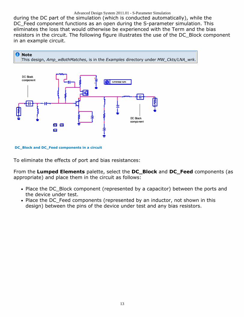
during the DC part of the simulation (which is conducted automatically), while theDC_Feed component functions as an open during the S-parameter simulation. Thiseliminates the loss that would otherwise be experienced with the Term and the biasresistors in the circuit. The following figure illustrates the use of the DC_Block componentin an example circuit.
NoteThis design, Amp_wBothMatches, is in the Examples directory under MW_Ckts/LNA_wrk.
DC_Block and DC_Feed components in a circuit
To eliminate the effects of port and bias resistances:
From the Lumped Elements palette, select the DC_Block and DC_Feed components (asappropriate) and place them in the circuit as follows:
Place the DC_Block component (represented by a capacitor) between the ports andthe device under test.Place the DC_Feed components (represented by an inductor, not shown in thisdesign) between the pins of the device under test and any bias resistors.
Advanced Design System 2011.01 - S-Parameter Simulation
14
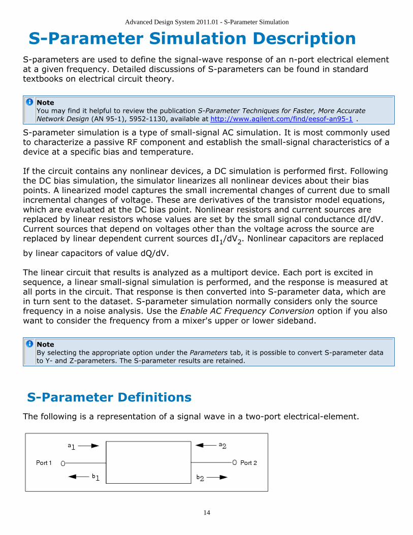
S-Parameter Simulation DescriptionS-parameters are used to define the signal-wave response of an n-port electrical elementat a given frequency. Detailed discussions of S-parameters can be found in standardtextbooks on electrical circuit theory.
NoteYou may find it helpful to review the publication S-Parameter Techniques for Faster, More AccurateNetwork Design (AN 95-1), 5952-1130, available at http://www.agilent.com/find/eesof-an95-1 .
S-parameter simulation is a type of small-signal AC simulation. It is most commonly usedto characterize a passive RF component and establish the small-signal characteristics of adevice at a specific bias and temperature.
If the circuit contains any nonlinear devices, a DC simulation is performed first. Followingthe DC bias simulation, the simulator linearizes all nonlinear devices about their biaspoints. A linearized model captures the small incremental changes of current due to smallincremental changes of voltage. These are derivatives of the transistor model equations,which are evaluated at the DC bias point. Nonlinear resistors and current sources arereplaced by linear resistors whose values are set by the small signal conductance dI/dV.Current sources that depend on voltages other than the voltage across the source arereplaced by linear dependent current sources dI1/dV2. Nonlinear capacitors are replaced
by linear capacitors of value dQ/dV.
The linear circuit that results is analyzed as a multiport device. Each port is excited insequence, a linear small-signal simulation is performed, and the response is measured atall ports in the circuit. That response is then converted into S-parameter data, which arein turn sent to the dataset. S-parameter simulation normally considers only the sourcefrequency in a noise analysis. Use the Enable AC Frequency Conversion option if you alsowant to consider the frequency from a mixer's upper or lower sideband.
NoteBy selecting the appropriate option under the Parameters tab, it is possible to convert S-parameter datato Y- and Z-parameters. The S-parameter results are retained.
S-Parameter DefinitionsThe following is a representation of a signal wave in a two-port electrical-element.
Advanced Design System 2011.01 - S-Parameter Simulation
15
where
a1 is the wave into port 1
b1 is the wave out of port 1
a2 is the wave into port 2
b2 is the wave out of port 2
The S-parameters for this conventional element are defined in standard microwavetextbooks as follows:
b1= a1s11+ a2s12
b2= a1s21+ a2s22
where
s11is the port-1 reflection coefficient: s11= b1/a1; a2= 0
s22is the port-2 reflection coefficient: s22=b2/a2; a1= 0
s21is the forward transmission coefficient: s21= b2/a1; a2= 0
s12is the reverse transmission coefficient: s12= b1/a2; a1= 0
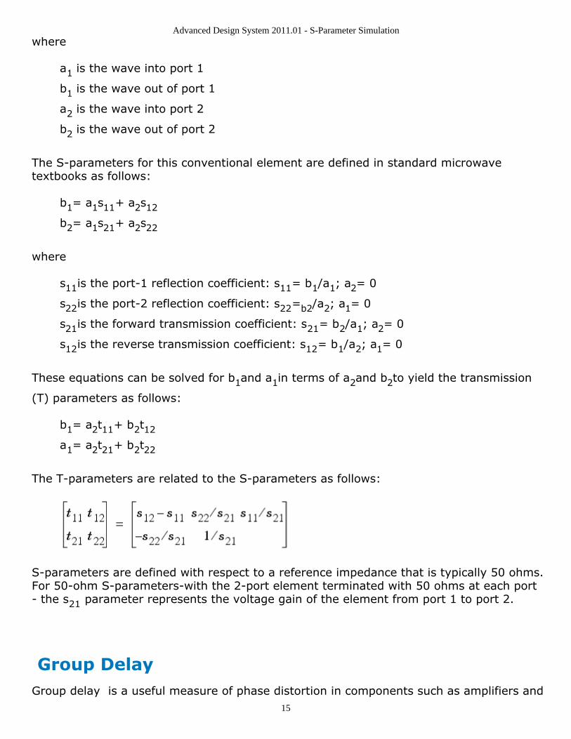
These equations can be solved for b1and a1in terms of a2and b2to yield the transmission
(T) parameters as follows:
b1= a2t11+ b2t12
a1= a2t21+ b2t22
The T-parameters are related to the S-parameters as follows:
S-parameters are defined with respect to a reference impedance that is typically 50 ohms.For 50-ohm S-parameters-with the 2-port element terminated with 50 ohms at each port- the s21 parameter represents the voltage gain of the element from port 1 to port 2.
Group DelayGroup delay is a useful measure of phase distortion in components such as amplifiers and
Advanced Design System 2011.01 - S-Parameter Simulation
16
filters. It measures the transit time, with respect to frequency, of a signal through thedevice under test.
The simulator calculates group delay by performing a finite difference of the phaseresponse to obtain dΦ/dω.
For more details on how the ADS S-parameter controller's group delay algorithm can beused with measured data, see the following support document:
ADS Group Delay Calculation On Measured Data
The simulator sets the frequency aperture to 0.01% of the current frequency. You canoverride this value by modifying the value in the Group delay aperture field, under theParameters tab. This function is similar to that found on network analyzers, like theAgilent 8710. Refer also to these functions:
delaydev_lin_phasediffphasedegphaseradripple (and GpDelRip measurement equation)unwrapvolt_gain
Descriptions are in Measurement Expressions (expmeas).
Group delay results are considered with respect to the input and output ports only. Resultsof group delay calculations include delay(2,1) and delay(1,2), which can be viewed in theData Display. These are absolute group delay, in seconds. For additional results data, addthe measurement equations dev_lin_phase and GpDelRip to the schematic. Calculationsfrom these equations will also be available in the Data Display.
S-Parameter Frequency ConversionS-parameter simulation normally allows only one frequency to be considered in a noiseanalysis - that of the source. This can be a disadvantage in obtaining simulation results forcircuits involving mixers, which are inherently frequency-translating devices involvingmultiple frequencies. (See Harmonic Balance for Mixers (cktsimhb).)
As an aid in the simulation of frequencies involving mixer subnetworks, the option EnableAC Frequency Conversion (under the Parameters tab) causes the simulator to considernot only the frequency of the source but also that of one of the mixer's sidebands (whichare defined by the user). Only the upper or lower sideband is considered, not both. Thefrequency-conversion results will appear in the dataset as for any nodes or probes placedto capture voltage or current data.
Advanced Design System 2011.01 - S-Parameter Simulation
17
The S-parameter simulator uses the same conversion algorithm used by the AC Simulationcomponent. For more information on this algorithm, see Enabling Frequency Conversion(cktsimac).
Advanced Design System 2011.01 - S-Parameter Simulation
18
S-Parameter Simulation Noise Analysis During an S-parameter simulation, you can calculate these noise characteristics:
Noise figureNoisy 2-port parameters
Each are discussed in the sections that follow.
For networks with more than two ports, the noise figure can be measured between twouser-specified ports using Input Port and Output Port; the other ports are treated asresistors for the noise simulation.
HintTo aid in noise figure measurements, use the noise circle measurement component, NsCircle or thefunction ns_circle. See ns circle() (expmeas).
Noise FigureThe parameter nf(k) in the dataset is the noise figure at output port k. You can viewresults using the Data Display. The noise figure for each port will appear in the variableslist as nf(1), nf(2), and so on. nf displays noise figures for all ports.
When noise figure is calculated at a port, the other ports in the network are terminated intheir respective impedances.
For a 2-port circuit, the noise figure is the signal-to-noise ratio at the input, divided by thesignal-to-noise ratio at the output. It has units of dB. For a circuit with more than twoports, the noise figure is the ratio of the total noise at the output port to the transmittedinput noise. The total noise is the transmitted input noise plus the noise contributed by thenetwork. The transmitted input noise represents the portion of the incident thermal noise(kTB, where k=Boltzmann's constant, 1.380658 x 10⁻²³ J/K, T=290 K, B=1 Hz) whichpasses through the system.
Calculating Noise FigureThe common definition of noise factor is signal to noise at the input divided by the signalto noise at the output or
This definition describes the way that noise is computed in Advanced Design System.
Advanced Design System 2011.01 - S-Parameter Simulation
19
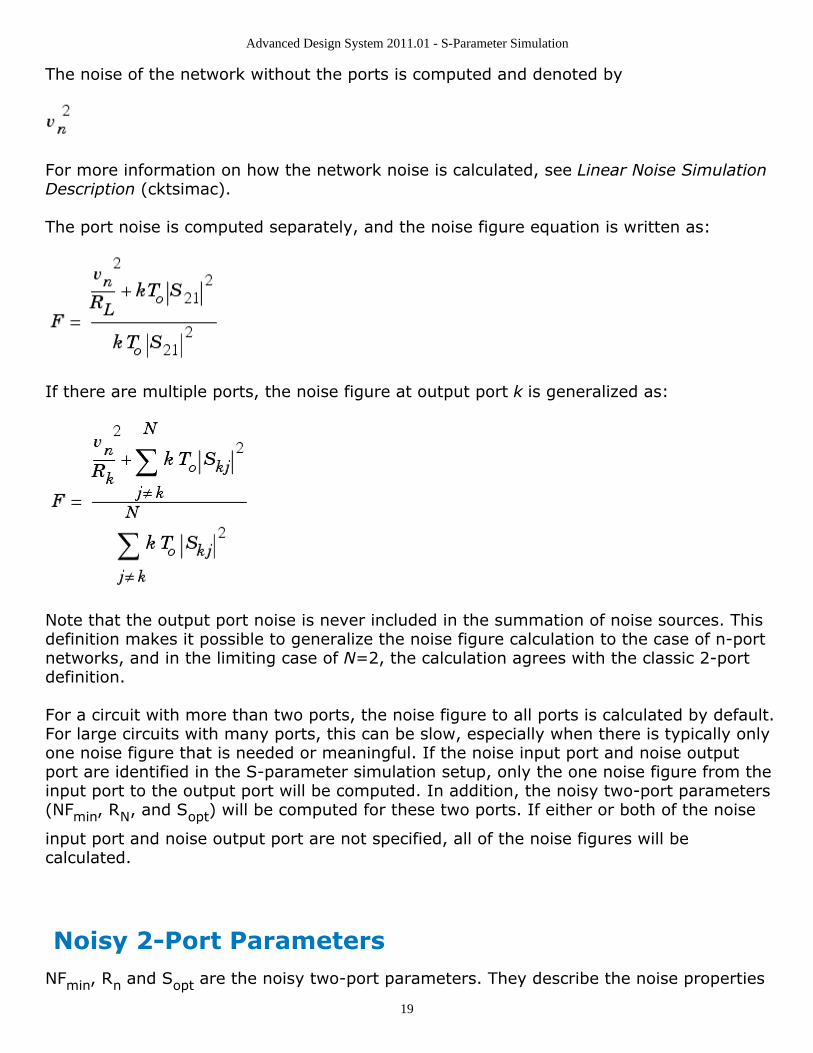
The noise of the network without the ports is computed and denoted by
For more information on how the network noise is calculated, see Linear Noise SimulationDescription (cktsimac).
The port noise is computed separately, and the noise figure equation is written as:
If there are multiple ports, the noise figure at output port k is generalized as:
Note that the output port noise is never included in the summation of noise sources. Thisdefinition makes it possible to generalize the noise figure calculation to the case of n-portnetworks, and in the limiting case of N=2, the calculation agrees with the classic 2-portdefinition.
For a circuit with more than two ports, the noise figure to all ports is calculated by default.For large circuits with many ports, this can be slow, especially when there is typically onlyone noise figure that is needed or meaningful. If the noise input port and noise outputport are identified in the S-parameter simulation setup, only the one noise figure from theinput port to the output port will be computed. In addition, the noisy two-port parameters(NFmin, RN, and Sopt) will be computed for these two ports. If either or both of the noise
input port and noise output port are not specified, all of the noise figures will becalculated.
Noisy 2-Port ParametersNFmin, Rn and Sopt are the noisy two-port parameters. They describe the noise properties
Advanced Design System 2011.01 - S-Parameter Simulation
20
of a two-port and how the noise changes with respect to the source impedance. Theydescribe circles of constant noise figure on the Smith chart.
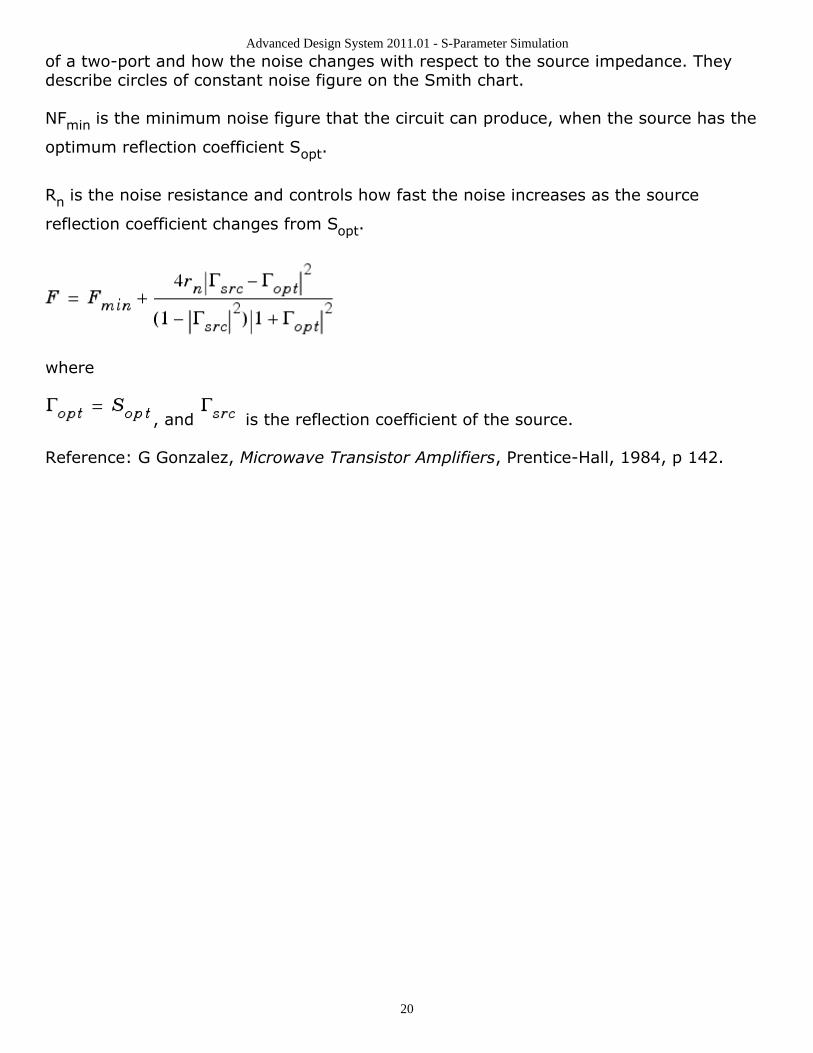
NFmin is the minimum noise figure that the circuit can produce, when the source has the
optimum reflection coefficient Sopt.
Rn is the noise resistance and controls how fast the noise increases as the source
reflection coefficient changes from Sopt.
where
, and is the reflection coefficient of the source.
Reference: G Gonzalez, Microwave Transistor Amplifiers, Prentice-Hall, 1984, p 142.
Advanced Design System 2011.01 - S-Parameter Simulation
21
S-Parameters from Various Input-Output ModesS-parameter results can be simulated for designs using various combinations of input andoutput modes. These modes include differential, common, and single-ended. AdvancedDesign System offers the following component and examples supporting varioustechniques for working with S-parameters:
SP_Diff is an instrument control component and is available in the Simulation-Instruments component library. See SP_Diff (Differential-Mode S-Parameters)(cktsiminst).The example workspace C:/Agilent/ADS2011_01/designguides/projects/Wirelinecontains the following designs and datasets that demonstrate simulations and mode-conversion equations. See the documentation for this workspace in Examples >Wireline > Wireline Applications then scroll to "Signal Integrity Simulations".
Common Mode Impedance Simulation is demonstrated inckt_common_imp_ML_thick_metal.Differential Impedance Simulation is demonstrated inckt_diff_imp_ML_thick_metal.Differential and Common Mode S-Parameter Basics is demonstrated inmixed_mode_basics.dds.
Advanced Design System 2011.01 - S-Parameter Simulation
22
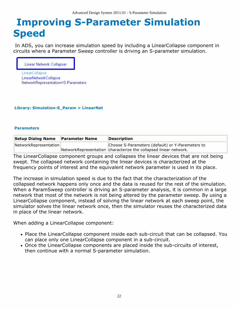
Improving S-Parameter SimulationSpeed In ADS, you can increase simulation speed by including a LinearCollapse component incircuits where a Parameter Sweep controller is driving an S-parameter simulation.
Library: Simulation-S_Param > LinearNet
Parameters
Setup Dialog Name Parameter Name Description
NetworkRepresentation NetworkRepresentation
Choose S-Parameters (default) or Y-Parameters tocharacterize the collapsed linear network.
The LinearCollapse component groups and collapses the linear devices that are not beingswept. The collapsed network containing the linear devices is characterized at thefrequency points of interest and the equivalent network parameter is used in its place.
The increase in simulation speed is due to the fact that the characterization of thecollapsed network happens only once and the data is reused for the rest of the simulation.When a ParamSweep controller is driving an S-parameter analysis, it is common in a largenetwork that most of the network is not being altered by the parameter sweep. By using aLinearCollapse component, instead of solving the linear network at each sweep point, thesimulator solves the linear network once, then the simulator reuses the characterized datain place of the linear network.
When adding a LinearCollapse component:
Place the LinearCollapse component inside each sub-circuit that can be collapsed. Youcan place only one LinearCollapse component in a sub-circuit.Once the LinearCollapse components are placed inside the sub-circuits of interest,then continue with a normal S-parameter simulation.
Advanced Design System 2011.01 - S-Parameter Simulation
23
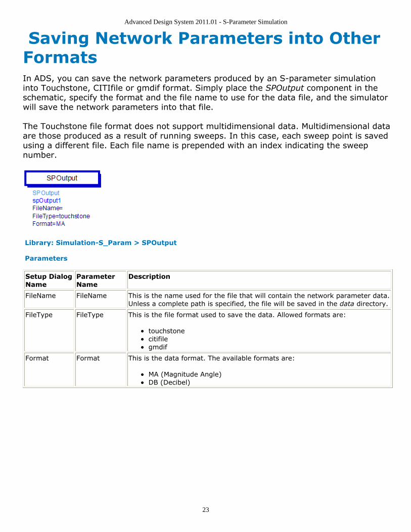
Saving Network Parameters into OtherFormatsIn ADS, you can save the network parameters produced by an S-parameter simulationinto Touchstone, CITIfile or gmdif format. Simply place the SPOutput component in theschematic, specify the format and the file name to use for the data file, and the simulatorwill save the network parameters into that file.
The Touchstone file format does not support multidimensional data. Multidimensional dataare those produced as a result of running sweeps. In this case, each sweep point is savedusing a different file. Each file name is prepended with an index indicating the sweepnumber.
Library: Simulation-S_Param > SPOutput
Parameters
Setup DialogName
ParameterName
Description
FileName FileName This is the name used for the file that will contain the network parameter data.Unless a complete path is specified, the file will be saved in the data directory.
FileType FileType This is the file format used to save the data. Allowed formats are:
touchstonecitifilegmdif
Format Format This is the data format. The available formats are:
MA (Magnitude Angle)DB (Decibel)
Advanced Design System 2011.01 - S-Parameter Simulation
24
S-Parameter Simulation Parameters ADS provides access to S-parameters simulation parameters enabling you to defineaspects of the simulation listed in the following table:
Tab Name Description For details, see...
Frequency Sweep type and associated characteristics. Setting Frequency Sweep
Parameters Provides options to set the following:
Calculation of S-, Y-, or Z-parameters orgroup delayFrequency conversionStatus levels for summary informationDevice operating point information level
Defining Simulation Parameters
Noise Parameters related to linear noise calculation(including port noise).
Defining Noise Parameters
Output Selectively save simulation data to a dataset. For details, see Selectively Saving and ControllingSimulation Data (cktsim).
Display Control the visibility of simulation parameterson the schematic.
For details, see Displaying Simulation Parameterson the Schematic (cktsim).
NoteIn ADS, the S-Parameters controller and the S-Parameter Test Lab controller both use the Scattering-Parameter Simulation dialog to set up a simulation. Use the following parameter information when usingthe setup dialog. For additional information about the S-Parameter Test Lab controller, see S-ParameterTest Labs and Sequencer (cktsim).
Setting Frequency SweepSetting up the sweep portion of the simulation consists of two basic parts:
Selecting the sweep type and setting the associated characteristicsOptionally, specifying a sweep plan
NoteIn ADS, the S-Parameters controller and the S-Parameter Test Lab controller both use theScattering-Parameter Simulation dialog to set up a simulation. Use the following parameterinformation when using the setup dialog. For additional information about the S-Parameter Test Labcontroller, see S-Parameter Test Labs and Sequencer (cktsim).
To shorten simulation time in any parameter sweep, select a start point as close aspossible to the convergence point and vary the parameter gradually. This yieldsbetter estimates for the next simulation, and achieves convergence more rapidly thanif the parameter were changed abruptly. The following table describes the parameterdetails. Names listed in the Parameter Name column are used in netlists and onschematics.
Advanced Design System 2011.01 - S-Parameter Simulation
25
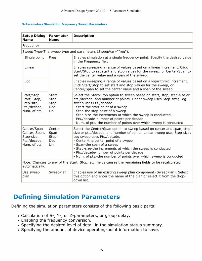
S-Parameters Simulation Frequency Sweep Parameters
Setup DialogName
ParameterName
Description
Frequency
Sweep Type-The sweep type and parameters (SweepVar="freq").
Single point Freq Enables simulation at a single frequency point. Specify the desired valuein the Frequency field.
Linear Enables sweeping a range of values based on a linear increment. ClickStart/Stop to set start and stop values for the sweep, or Center/Span toset the center value and a span of the sweep.
Log Enables sweeping a range of values based on a logarithmic increment.Click Start/Stop to set start and stop values for the sweep, orCenter/Span to set the center value and a span of the sweep.
Start/StopStart, Stop,Step-size,Pts./decade,Num. of pts.
StartStopStepDecLin
Select the Start/Stop option to sweep based on start, stop, step-size orpts./decade, and number of points. Linear sweep uses Step-size; Logsweep uses Pts./decade.- Start-the start point of a sweep- Stop-the stop point of a sweep- Step-size-the increments at which the sweep is conducted- Pts./decade-number of points per decade- Num. of pts.-the number of points over which sweep is conducted
Center/SpanCenter, Span,Step-size,Pts./decade,Num. of pts.
CenterSpanStepDecLin
Select the Center/Span option to sweep based on center and span, step-size or pts./decade, and number of points. Linear sweep uses Step-size;Log sweep uses Pts./decade.- Center-the center point of a sweep- Span-the span of a sweep- Step-size-the increments at which the sweep is conducted- Pts./decade-number of points per decade- Num. of pts.-the number of points over which sweep is conducted
Note: Changes to any of the Start, Stop, etc. fields causes the remaining fields to be recalculatedautomatically.
Use sweepplan
SweepPlan Enables use of an existing sweep plan component (SweepPlan). Selectthis option and enter the name of the plan or select it from the drop-down list.
Defining Simulation ParametersDefining the simulation parameters consists of the following basic parts:
Calculation of S-, Y-, or Z-parameters, or group delay.Enabling the frequency conversion.Specifying the desired level of detail in the simulation status summary.Specifying the amount of device operating-point information to save.
Advanced Design System 2011.01 - S-Parameter Simulation
26
NoteIn ADS, the S-Parameters controller and the S-Parameter Test Lab controller both use theScattering-Parameter Simulation dialog to set up a simulation. Use the following parameterinformation when using the setup dialog. For additional information about the S-Parameter Test Labcontroller, see S-Parameter Test Labs and Sequencer (cktsim).
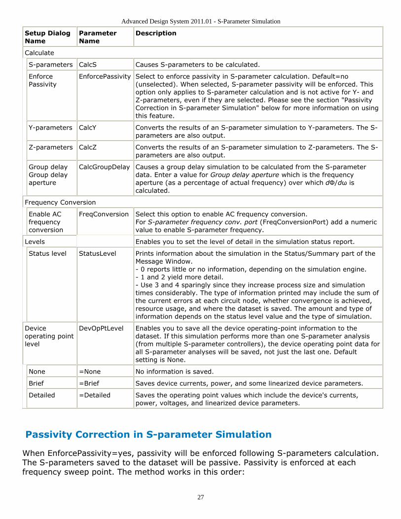
The following table describes the parameter details. Names listed in the ParameterName column are used in netlists and on schematics.
S-Parameters Simulation Parameters
Advanced Design System 2011.01 - S-Parameter Simulation
27
Setup DialogName
ParameterName
Description
Calculate
S-parameters CalcS Causes S-parameters to be calculated.
EnforcePassivity
EnforcePassivity Select to enforce passivity in S-parameter calculation. Default=no(unselected). When selected, S-parameter passivity will be enforced. Thisoption only applies to S-parameter calculation and is not active for Y- andZ-parameters, even if they are selected. Please see the section "PassivityCorrection in S-parameter Simulation" below for more information on usingthis feature.
Y-parameters CalcY Converts the results of an S-parameter simulation to Y-parameters. The S-parameters are also output.
Z-parameters CalcZ Converts the results of an S-parameter simulation to Z-parameters. The S-parameters are also output.
Group delayGroup delayaperture
CalcGroupDelay Causes a group delay simulation to be calculated from the S-parameterdata. Enter a value for Group delay aperture which is the frequencyaperture (as a percentage of actual frequency) over which dΦ/dω iscalculated.
Frequency Conversion
Enable ACfrequencyconversion
FreqConversion Select this option to enable AC frequency conversion.For S-parameter frequency conv. port (FreqConversionPort) add a numericvalue to enable S-parameter frequency.
Levels Enables you to set the level of detail in the simulation status report.
Status level StatusLevel Prints information about the simulation in the Status/Summary part of theMessage Window.- 0 reports little or no information, depending on the simulation engine.- 1 and 2 yield more detail.- Use 3 and 4 sparingly since they increase process size and simulationtimes considerably. The type of information printed may include the sum ofthe current errors at each circuit node, whether convergence is achieved,resource usage, and where the dataset is saved. The amount and type ofinformation depends on the status level value and the type of simulation.
Deviceoperating pointlevel
DevOpPtLevel Enables you to save all the device operating-point information to thedataset. If this simulation performs more than one S-parameter analysis(from multiple S-parameter controllers), the device operating point data forall S-parameter analyses will be saved, not just the last one. Defaultsetting is None.
None =None No information is saved.
Brief =Brief Saves device currents, power, and some linearized device parameters.
Detailed =Detailed Saves the operating point values which include the device's currents,power, voltages, and linearized device parameters.
Passivity Correction in S-parameter Simulation
When EnforcePassivity=yes, passivity will be enforced following S-parameters calculation.The S-parameters saved to the dataset will be passive. Passivity is enforced at eachfrequency sweep point. The method works in this order:
Advanced Design System 2011.01 - S-Parameter Simulation
28
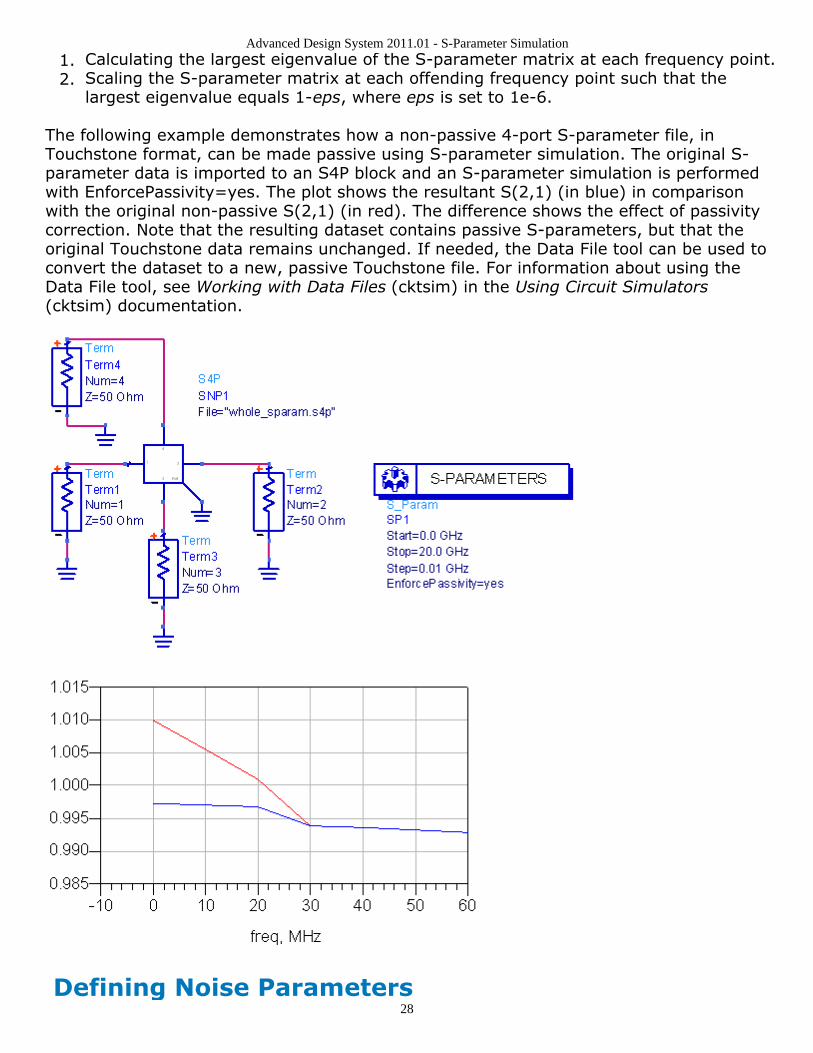
Calculating the largest eigenvalue of the S-parameter matrix at each frequency point.1.Scaling the S-parameter matrix at each offending frequency point such that the2.largest eigenvalue equals 1-eps, where eps is set to 1e-6.
The following example demonstrates how a non-passive 4-port S-parameter file, inTouchstone format, can be made passive using S-parameter simulation. The original S-parameter data is imported to an S4P block and an S-parameter simulation is performedwith EnforcePassivity=yes. The plot shows the resultant S(2,1) (in blue) in comparisonwith the original non-passive S(2,1) (in red). The difference shows the effect of passivitycorrection. Note that the resulting dataset contains passive S-parameters, but that theoriginal Touchstone data remains unchanged. If needed, the Data File tool can be used toconvert the dataset to a new, passive Touchstone file. For information about using theData File tool, see Working with Data Files (cktsim) in the Using Circuit Simulators(cktsim) documentation.
Defining Noise Parameters
Advanced Design System 2011.01 - S-Parameter Simulation
29
Defining the noise parameters consists of the following basic parts:
Enabling noise calculation.Specifying the nodes to use for noise parameter calculation.Specifying the noise contributors and the threshold for noise contribution.Optionally, specifying the bandwidth over which the noise simulation is performed.
NoteIn ADS, the S-Parameters controller and the S-Parameter Test Lab controller both use theScattering-Parameter Simulation dialog to set up a simulation. Use the following parameterinformation when using the setup dialog. For additional information about the S-Parameter Test Labcontroller, see S-Parameter Test Labs and Sequencer (cktsim).
The following table describes the parameter details. Names listed in the ParameterName column are used in netlists and on schematics.
S-Parameters Simulation Noise Parameters
Advanced Design System 2011.01 - S-Parameter Simulation
30
SetupDialogName
Parameter Name Description
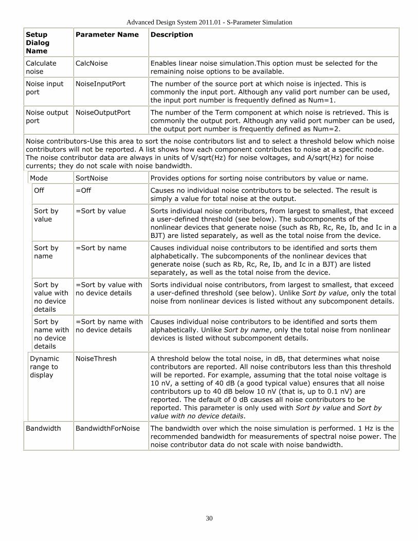
Calculatenoise
CalcNoise Enables linear noise simulation.This option must be selected for theremaining noise options to be available.
Noise inputport
NoiseInputPort The number of the source port at which noise is injected. This iscommonly the input port. Although any valid port number can be used,the input port number is frequently defined as Num=1.
Noise outputport
NoiseOutputPort The number of the Term component at which noise is retrieved. This iscommonly the output port. Although any valid port number can be used,the output port number is frequently defined as Num=2.
Noise contributors-Use this area to sort the noise contributors list and to select a threshold below which noisecontributors will not be reported. A list shows how each component contributes to noise at a specific node.The noise contributor data are always in units of V/sqrt(Hz) for noise voltages, and A/sqrt(Hz) for noisecurrents; they do not scale with noise bandwidth.
Mode SortNoise Provides options for sorting noise contributors by value or name.
Off =Off Causes no individual noise contributors to be selected. The result issimply a value for total noise at the output.
Sort byvalue
=Sort by value Sorts individual noise contributors, from largest to smallest, that exceeda user-defined threshold (see below). The subcomponents of thenonlinear devices that generate noise (such as Rb, Rc, Re, Ib, and Ic in aBJT) are listed separately, as well as the total noise from the device.
Sort byname
=Sort by name Causes individual noise contributors to be identified and sorts themalphabetically. The subcomponents of the nonlinear devices thatgenerate noise (such as Rb, Rc, Re, Ib, and Ic in a BJT) are listedseparately, as well as the total noise from the device.
Sort byvalue withno devicedetails
=Sort by value withno device details
Sorts individual noise contributors, from largest to smallest, that exceeda user-defined threshold (see below). Unlike Sort by value, only the totalnoise from nonlinear devices is listed without any subcomponent details.
Sort byname withno devicedetails
=Sort by name withno device details
Causes individual noise contributors to be identified and sorts themalphabetically. Unlike Sort by name, only the total noise from nonlineardevices is listed without subcomponent details.
Dynamicrange todisplay
NoiseThresh A threshold below the total noise, in dB, that determines what noisecontributors are reported. All noise contributors less than this thresholdwill be reported. For example, assuming that the total noise voltage is10 nV, a setting of 40 dB (a good typical value) ensures that all noisecontributors up to 40 dB below 10 nV (that is, up to 0.1 nV) arereported. The default of 0 dB causes all noise contributors to bereported. This parameter is only used with Sort by value and Sort byvalue with no device details.
Bandwidth BandwidthForNoise The bandwidth over which the noise simulation is performed. 1 Hz is therecommended bandwidth for measurements of spectral noise power. Thenoise contributor data do not scale with noise bandwidth.