Embed Size (px)
Citation preview

Specialty Module SpecificationS
ChapterChapterChapter
444In This Chapter...
P2-HSI High-Speed Input Module Overview ............................................................4–2HSI LED Indicators ....................................................................................................4–3HSI Input Specifications ............................................................................................4–4HSI Status Output Specifications ..............................................................................4–6Frequency Response .................................................................................................4–6HSI Wiring Examples ................................................................................................4–8
P2-HSO High-Speed Output Module Overview ......................................................4–11HSI LED Indicators ..................................................................................................4–12HSI Output Specifications .......................................................................................4–13HSO Wiring Examples ............................................................................................4–15
High-Speed Module Tester Utility...........................................................................4–20
P2-SCM Module Overview ......................................................................................4–21SCM LED Indicators ................................................................................................4–22P2-SCM Module Communications .........................................................................4–23
RS-232 Serial Ports ..............................................................................................4–23RS-232 Serial Port 1 ............................................................................................4–24RS-232 Serial Port 2 and 3 ..................................................................................4–25RS-485 Port 4 ......................................................................................................4–26

Chapter 4: Specialty Module Specifications
1
2
34
5
6
7
8
9
10
11
12
13
14
A
B
C
D
Hardware User Manual, 1st Edition, Rev. D4–2 2000
No terminal block sold for this module; ZIPLink required. See Chapter 5 for part numbers of ZIPLink cables and connection modules required with this module.
General SpecificationsModule Type Intelligent
Modules per Base 15 Maximum (See Note)
I/O Points Used None, mapped directly to tags in CPU
Operating Temperature 0º to 60ºC (32º to 140ºF)
Storage Temperature -20º to 70ºC (-4º to 158ºF)
Humidity 5 to 95% (non-condensing)
Environmental Air No corrosive gases permitted
Vibration IEC 60068-2-6 (Test Fc)
Shock IEC 60068-2-27 (Test Ea)Field to Logic Side Isolation
1800VAC applied for 1 second
Insulation Resistance >10MΩ @ 500VDC
Heat Dissipation 5.76 W
Enclosure Type Open Equipment
Agency ApprovalsUL508 File E139594, Canada & USA CE (EN61131-2)*
Module Location Any I/O slot in a Productivity2000 System
Field WiringUse ZIPLink Wiring System ONLY. See “Wiring Options” in Chapter 5.
EU Directive
See the “EU Directive” topic in the Productivity Suite Help File. Information can also be obtained at: www.productivity2000.com
Weight 90g (3.2 oz)* Meets EMC and Safety requirements. See the D.O.C. for details.
P2-HSI High-Speed Input Module OverviewThe P2-HSI High-Speed (1MHz) Input Module provides differential (line receiver, 5V max) and single ended (5-24V) inputs that accept up to 1MHz of pulse/direction and quadrature signals on each of the two independent input channels. Additionally, four 5-24 VDC general purpose high-speed inputs and four general purpose, 5-24 VDC 0.5 amp, outputs are included for use with any Productivity2000 system.
Use the hardware configuration tool in the Productivity Suite programming software to setup the P2-HSI module. See the Productivity Suite help file.
ULC USR
NOTE: For complete system limits, please refer to the “Hardware and Communication Limits” table in the Productivity Suite online “Help” file “Hardware Configuration”, topic P050.

Chapter 4: Specialty Module Specifications
1
2
34
5
6
7
8
9
10
11
12
13
14
A
B
C
D
4–3 Hardware User Manual, 1st Edition, Rev. D2000
Connector SpecificationsConnector Type IDC style header with latch, Omron XG4A-4034
Number of Pins 40 point
Pitch 0.1 in (2.54 mm)
Power SpecificationsExternal Power 24VDC -15% / +10%, Class 2
Maximum Voltage 26.4 VDC
Minimum Voltage 20.4 VDCCurrent Consumption Excluding Outputs 50mA
Maximum Current Consumption Total of the 4 Status Outputs 2A
Status LEDsFault Status LEDs (F) 1, 2, 3 & 4 (one per status output)
Input LEDs(IN) 1A, 1B, 1Z, 2A, 2B, 2Z, IN3 & IN4 (one per status input)
Output Status LEDs (O) OUT1, OUT 2, OUT3 & OUT4
P2-HSI High-Speed Input Module (continued)
Note: All front panel fault LED’s blinking indicates loss of 24VDC external power to module.
HSI LED Indicators

Chapter 4: Specialty Module Specifications
1
2
34
5
6
7
8
9
10
11
12
13
14
A
B
C
D
Hardware User Manual, 1st Edition, Rev. D4–4 2000
*The Z pulse input (1Z & 2Z) is capable of capturing a 1MHz wide pulse for the purpose of resetting an encoder count but a 3 microsecond pause (300kHz) is required between pulses.NOTE: The voltage difference between the input pairs must be between 3 volts and 5.6 volts.
Differential (5V) Input SpecificationsPulse Inputs* Differential inputs (6 pts: 1A, 1B, 1Z, 2A,
2B, 2Z)
Isolation Each input is isolated from other circuitsInput Signal Type, per Channel Select Differential
Input Volts 5VDC
Input Volts Maximum ±5.6 VDC, limited by protection
Input Impedance 200Ω minimum, 500Ω maximum
Input Rated Current 5VDC, 15mA (8mA typical, 15mA maximum)
Input Minimum ON Voltage 3.0 VDC
Input Maximum OFF Voltage 1.0 VDC
Input Minimum ON Current 5.0 mA
Input Maximum OFF Current 2.0 mA
OFF to ON Response Time1A, 1B, 2A, 2B: 0.48 μs1Z, 2Z, 3IN, 4IN: 6μs
ON to OFF Response Time1A, 1B, 2A, 2B: 0.48 μs1Z, 2Z, 3IN, 4IN: 6μs
Max. Input Frequency1A, 1B, 2A, 2B: 1MHz1Z, 2Z, 3IN, 4IN: 200kHz
HSI Input Specifications
P2-HSI High-Speed Input Module (continued)

Chapter 4: Specialty Module Specifications
1
2
34
5
6
7
8
9
10
11
12
13
14
A
B
C
D
4–5 Hardware User Manual, 1st Edition, Rev. D2000
Single Ended (5-24V) Input SpecificationsStatus Input Single ended inputs (8 pts: 1A, 1B, 1Z,
2A, 2B, 2Z, 3IN, 4IN)
Isolation Each input is isolated from other circuits
Input Volts Range 5–24 VDC
Input Volts Maximum ±34VDC, limited by protection
Input Impedance 1kΩ minimum, 5kΩ maximum
Inputs Rated Current5–24 VDC, 16mA 5.2 mA typical @ 5VDC 22mA maximum @ 34VDC
Input Minimum ON Voltage 4.5 VDC
Input Maximum OFF Voltage 2.0 VDC
Input Minimum ON Current 5.0 mA
Input Maximum OFF Current 1.4 mA
OFF to ON Response Time 1A, 1B, 2A, 2B: 0.48 μs1Z, 2Z, 3IN, 4IN: 6μs
ON to OFF Response Time 1A, 1B, 2A, 2B: 0.48 μs1Z, 2Z, 3IN, 4IN: 6μs
Max. Input Frequency* 1A, 1B, 2A, 2B: 1MHz1Z, 2Z, 3IN, 4IN: 200kHz
* Inputs are not limited to this speed however, single ended signals are not usually reliable above 200kHz due to cabling capacitance.
HSI Input Specifications
P2-HSI High-Speed Input Module (continued)

Chapter 4: Specialty Module Specifications
1
2
34
5
6
7
8
9
10
11
12
13
14
A
B
C
D
Hardware User Manual, 1st Edition, Rev. D4–6 2000
Inaccuracy of Frequency Measurements Due to Time Base Errors25MHz Crystal for Time Base
Inaccuracy at 25°C, Maximum ±30PPM
Inaccuracy 0–60°C, Referenced to 25°C ±30PPM
Inaccuracy Due to Aging, Maximum ±5PPM/Year
Max. Time Base Inaccuracy 0–60°C and 10 Years Operation 0.01%
Frequency Response
Resolution of Frequency Measurements for “Fast Mode”Input Frequency Sampling Period Resolution
1Hz to 1MHz 1000ms ±1Hz10Hz to 1MHz 100ms ±10Hz100Hz to 1MHz 10ms ±100Hz1MHz 1ms ±1000Hz
Status Output SpecificationsStatus Outputs 4 sink/sourceOutput Signal Type, per Channel Select Current Sinking Current Sourcing
Operating Voltage¹ 5–24 VDC 5–24 VDC¹
Output Volts Maximum 36VDC 26.4 VDC¹
Output Current Maximum 500mA
Overcurrent Protection Short circuit detect and current limit with automatic retry for each output
Output Self Limiting Current 1.2 to 2.4 A
Max Inrush Current Self limited
Output Voltage Drop 0.7 VDC @ 0.5 A
Thermal Protection Independent over temperature protection each output
Output Voltage Clamp During Inductive Switching +45VDC -20VDC
Maximum OFF to ON Response 25μs²
Maximum ON to OFF Response 25μs²NOTES:1. Operating voltage of current sourcing outputs must be no greater than external
power.2. Measured at 5VDC operating voltage, 0.5 A load curent.
HSI Status Output SpecificationsP2-HSI High-Speed Input Module (continued)
Chapter 4: Specialty Module Specifications
1
2
34
5
6
7
8
9
10
11
12
13
14
A
B
C
D
4–7 Hardware User Manual, 1st Edition, Rev. D2000
Module Range: Target position range ±2.147 billion (32-bit signed integer)
Inaccuracy of Frequency Measurements¹,²,³,⁴ for “Auto Mode”Input Frequency Step/Dir Quadrature 1X Quadrature 4X1Hz
±1Hz ±1Hz ±1Hz10Hz100Hz 1kHz10kHz ±100Hz ±100Hz ±100Hz100kHz ±1000Hz ±1000Hz ±1000Hz1MHz ±10000Hz ±10000Hz ±10000Hz1. For stable input signal at given input frequency.2. For total measurement error add the time base error to the tabulated error.3. Maximum sample period: 1 second.4. Minimum sample period: 0.001 seconds.
Inaccuracy of Frequency Measurements¹,² for “Slow Mode”Input Frequency Step/Dir Quadrature 1X Quadrature 4X1Hz ±0.002 Hz ±0.002 Hz ±0.002 Hz10Hz ±0.009 Hz ±0.009 Hz ±0.009 Hz100Hz ±0.015 Hz ±0.015 Hz ±0.015 Hz1kHz ±1Hz ±1Hz ±1Hz10kHz ±100Hz ±100Hz ±100Hz100kHz ±1000Hz ±1000Hz ±1000Hz1MHz ±40000Hz ±40000Hz ±40000Hz
NOTE: Refer to the I/O Module Configuration Help file topic (P212) in the Productivity Suite Software for more information on Mode selections.
Frequency Response
Inaccuracy of Frequency Measurements¹,² for “Fast Mode”Input Frequency Sampling Period Step/
DirQuadrature 1X Quadrature 4X
1Hz
±1 Second ±1Hz ±1Hz ±1Hz
10Hz100Hz 1kHz10kHz100kHz1MHz
P2-HSI High-Speed Input Module (continued)

Chapter 4: Specialty Module Specifications
1
2
34
5
6
7
8
9
10
11
12
13
14
A
B
C
D
Hardware User Manual, 1st Edition, Rev. D4–8 2000
Status Outputs Wiring Diagram
Status Inputs Wiring Diagram
PWR+
D
S
SNK
SRC
OU
T1
+LOAD
D
S
SNK
SRC
OU
T2
D
S +LOAD
SNK
SRC
OU
T3
D
S +LOAD
SNK
SRC
OU
T4
+LOAD
PWR-
+
24VDC
+
5VDCto
24VDC
When 2nd power supply is used, negative terminal mustbe tied to PWR- terminal.
Sinking Outputs
Sourcing Outputs
Driv
ers
P2-HSI
B
C
E
A
+
IN3+
IN3-
IN4+
IN4-
2K Ohm
2K Ohm
-1Z
+1Z
-2Z
+2Z
2K Ohm
2K Ohm
P2-HSI
-
B
C
E -
Sensor
Sensor
+
Sinking Field Device
Sourcing Field Device+
5VDC to 24VDC
P2-HSI High-Speed Input Module (continued)HSI Wiring Examples
Chapter 4: Specialty Module Specifications
1
2
34
5
6
7
8
9
10
11
12
13
14
A
B
C
D
4–9 Hardware User Manual, 1st Edition, Rev. D2000
DAA
1A
1A 169 Ohm
DBB
1B
1B 169 Ohm
D
C
C
1Z
1Z 169 Ohm
P2-HSI
Sensor
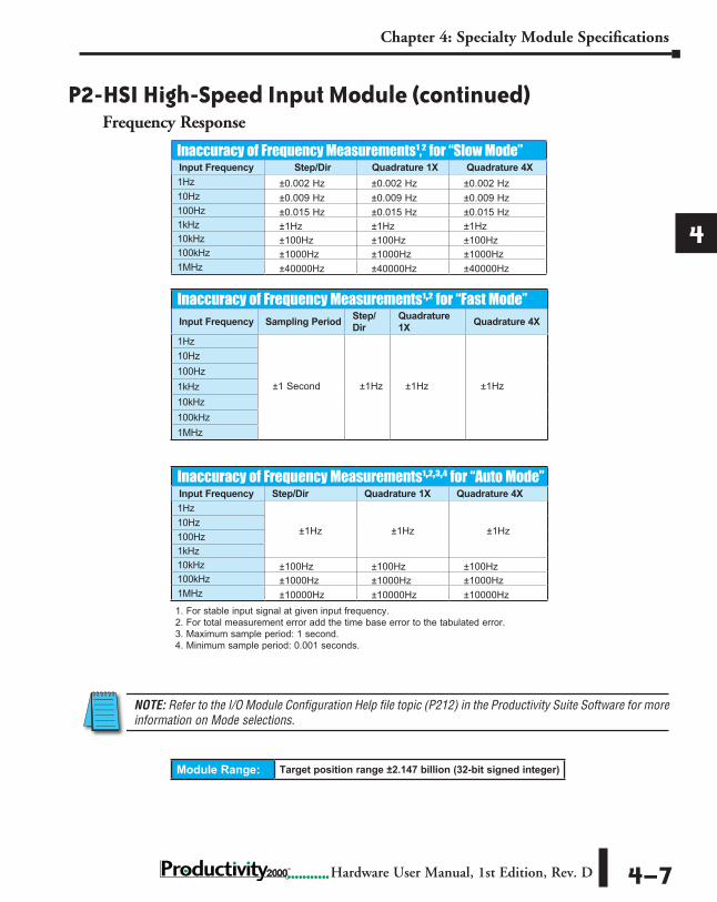
Encoder with 5VLine Drivers
Belden 3105A shielded, twisted pair, low capacitance.
Dead head shield this end.Tie shield to panel ground this end.
To prevent damage to P2-HSI 5V inputs,do not exceed 6.8V or 30 mA on inputs1A, 1A, 1B, 1B, 1Z, 1Z, 2A, 2A, 2B, 2B, 2Z, & 2Z.
BC
E
A
+
-1A
+1A 2K Ohm
-1B
+1B 2K Ohm
-1Z
+1Z 2K Ohm
P2-HSI
BC
E
B
BC
E
Z
-
Sensor Belden 3105A shielded, twisted pair, low capacitance.
Dead head shield this end.
Tie shield to panel ground this end.
+5VDC to 24VDC
24V Encoder Inputs Wiring Diagram
5V Encoder Inputs Wiring Diagram
P2-HSI High-Speed Input Module (continued)

Chapter 4: Specialty Module Specifications
1
2
34
5
6
7
8
9
10
11
12
13
14
A
B
C
D
Hardware User Manual, 1st Edition, Rev. D4–10 2000
Sinking I/O Wiring Diagram
Sourcing I/O Wiring Diagram
+1A+1B
+1Z
+2A+2B
+2ZIN3+ IN4+
OUT1SNK
OUT2SNK
LOAD
OUT4SNK+
+
24VDC
5VDCto
24VDC
PanelGND.
LOAD
OUT3SNK
LOAD
LOAD
Do not exceed 6.8V on these inputs
OUT1, OUT2, OUT3, & OUT4 SNK are 500mA Max. Load
1A OUT1SRC
OUT1SNK
OUT2SNK
OUT2SRC SH SHOUT3
SNKOUT3SRC1A 1B 1B 1Z 1Z 2A 2A 2B 2B 2Z 2Z
-1A +1A OUT4SNK
OUT4SRC
PWR+
PWR-
IN3+
IN3-
IN4+
IN4--1B +1B -1Z +1Z -2A +2A -2B +2B -2Z +2Z
P2-HSI High-Speed Input Module (continued)
-1A-1A -1B -1Z -2A -2B -2Z IN3- IN4-
LOAD
OUT4SRC
+
+24
VDC
PanelGND.
5VDCto
24VDC
OUT1SRC
OUT2SRC
LOAD
OUT3SRC
LOAD
LOAD
Do not exceed 6.8V on these inputs
OUT1, OUT2, OUT3, & OUT4SRC are 500mA Max. Load
1A OUT1SRC
OUT1SNK
OUT2SNK
OUT2SRC SH SHOUT3
SNKOUT3SRC1A 1B 1B 1Z 1Z 2A 2A 2B 2B 2Z 2Z
-1A +1A OUT4SNK
OUT4SRC
PWR+
PWR-
IN3+
IN3-
IN4+
IN4--1B +1B -1Z +1Z -2A +2A -2B +2B -2Z +2Z

Chapter 4: Specialty Module Specifications
1
2
34
5
6
7
8
9
10
11
12
13
14
A
B
C
D
4–11 Hardware User Manual, 1st Edition, Rev. D2000
P2-HSO High-Speed Output Module Overview
No terminal block sold for this module; ZIPLink required. See Chapter 5 for part numbers of ZIPLink cables and connection modules required with this module.
The P2-HSO High-Speed Output Module provides up to of (1MHz) pulse/direction, up/down and quadrature pulse output on each of two independent output channels. Additionally, six 5-24 VDC general purpose inputs and four 5-24 VDC general purpose outputs are included for use with the Productivity2000 System. Use the hardware configuration tool in the Productivity Suite programming software to setup the HSO module. See the Productivity Suite help file.
General SpecificationsModule Type IntelligentModules per Base 15 Maximum (See Note)I/O Points Used None, mapped directly to tags in CPUOperating Temperature 0º to 60ºC (32º to 140ºF)Storage Temperature -20º to 70ºC (-4º to 158ºF)Humidity 5 to 95% (non-condensing)Environmental Air No corrosive gases permittedVibration IEC 60068-2-6 (Test Fc)Shock IEC 60068-2-27 (Test Ea)Field to Logic Side Isolation 1800VAC applied for 1 secondInsulation Resistance >10MΩ @ 500VDCHeat Dissipation 6.26 WEnclosure Type Open Equipment
Emissions EN61000-6-4 (Conducted and Radiated RF Emissions)
Agency Approvals UL508 File E139594, Canada & USA CE (EN61131-2*)
Module Keying to Backplane ElectronicModule Location Any I/O slot in a Productivity2000 System
Field Wiring Use ZIPLink Wiring System ONLY. See “Wiring Options” in Chapter 5.
EU DirectiveSee the “EU Directive” topic in the Productivity Suite Help File. Information can also be obtained at: www.productivity2000.com
Weight 90g (3.2 oz)
NOTE: For complete system limits, please refer to the “Hardware and Communication Limits” table in the Productivity Suite online “Help” file “Hardware Configuration”, topic P050.
ULC USR

Chapter 4: Specialty Module Specifications
1
2
34
5
6
7
8
9
10
11
12
13
14
A
B
C
D
Hardware User Manual, 1st Edition, Rev. D4–12 2000
Note: All front panel fault LED’s blinking indicates loss of 24VDC external power to module.
Status LEDsFault Status LEDs (F) 1, 2, 3, 4, 5, 6 (one per pulse output and one per
status output)
Input LEDs (IN) 1, 2, 3, 4, 5, 6 (one per status input)
Output Status LEDs (O) OUT 1A & 1B, OUT 2A & 2B, OUT 3, 4, 5, 6
Power SpecificationsExternal Power 24VDC -15% / +10%, Class 2
Maximum Voltage 26.4 VDC
Minimum Voltage 20.4 VDCCurrent Consumption Excluding Outputs 130mA
Maximum Current Consumption Total of the 4 Status Outputs 2A
Connector SpecificationsConnector Type IDC style header with latch, Omron XG4A-4034
Number of Pins 40 point
Pitch 0.1 in (2.54 mm)
P2-HSO High-Speed Output Module (continued)
HSI LED Indicators

Chapter 4: Specialty Module Specifications
1
2
34
5
6
7
8
9
10
11
12
13
14
A
B
C
D
4–13 Hardware User Manual, 1st Edition, Rev. D2000
P2-HSO High-Speed Output Module (continued)
Pulse Output SpecificationsPulse Outputs 2 Channels
Output Pulse Type, per Channel Select
Selectable for pulse & direction, up/down or quadrature
Output Signal Type, per Channel Select
RS-422 Line Driver Current Sinking and Sourcing
Open Drain FET Outputs Current Sinking
Output Volts RS-422 levels 24VDC
Output Volts Maximum 5VDC 36VDC
Protection for Overcurrent and Short Circuit to Power
Current limit and thermal shutdown²
Current limit and thermal shutdown¹
Protection Short to Ground Yes Yes
Overcurrent Trip Level Output current limit ±200mA max² 100mA minimum
Maximum Continuous Output Current ±60mA 40mA
Maximum Switching Frequency, 1m cable3 1MHz 500kHz
Maximum Switching Frequency, 10m cable3 1MHz 200kHz
NOTES: 1. Any fault shuts off the output. Fault is indicated and output is kept off until a new
move start is received.2. RS-422 thermal faults auto reset after device cool down.3. Outputs are not limited to these speeds but single ended signals produced by the
FETs are not usually reliable above these speeds due to cabling capacitance.
Status Input SpecificationsStatus Input 6 sink/source
Isolation Each status input is individually isolated from all other circuits
Input Volts Range 5-24 VDC
Input Volts Maximum 34VDC, limited by protection
Input Impedance 1kΩ minimum, 5kΩ maximum
Inputs Rated Current5–24 VDC, 16mA 5.2 mA typical @ 5VDC 22mA maximum @ 34VDC
Input Minimum ON Voltage 4.5 VDC
Input Maximum OFF Voltage 2.0 VDC
Input Minimum ON Current 5.0 mA
Input Maximum OFF Current 1.4 mA
OFF to ON Response Time 4μs
ON to OFF Response Time 4μs
HSI Output Specifications

Chapter 4: Specialty Module Specifications
1
2
34
5
6
7
8
9
10
11
12
13
14
A
B
C
D
Hardware User Manual, 1st Edition, Rev. D4–14 2000
Module Range: Target position range ±2.147 billion (32-bit signed integer)
Status Output SpecificationsStatus Outputs 4 sink/sourceOutput Signal Type, per Channel Select Current Sinking Current Sourcing
Operating Voltage² 5–24 VDC 5–24 VDC²Output Volts Maximum² 36VDC 26.4 VDC²Output Current Maximum 500mA
Overcurrent Protection Short circuit detect, overcurrent shutdown¹Output Self Limiting Current 1.2 to 2.4 A
Max Inrush Current Self limited
Output Voltage Drop 0.7 VDC @ 0.5 A
Thermal Protection Independent over temperature protection each output
Output Voltage Clamp During Inductive Switching +45VDC -20VDC
Maximum OFF to ON Response 25μs3
Maximum ON to OFF Response 25μs3
NOTES:1. Any fault shuts off the output. Fault is indicated and output is kept off until a
new move start is received.2. Operating voltage for current sourcing outputs must be less or equal to the
external power.3. Measured at 5VDC operating voltage, 0.5 A load.
Resolution of Frequency Output MeasurementsOutput Frequency Resolution1kHz 0.01 Hz10kHz 0.67 Hz100kHz 67Hz1MHz 6622Hz
Inaccuracy of Output Frequency Due to Time Base Errors25 MHz Crystal for Time Base
Inaccuracy at 25°C, Maximum ±30PPM
Inaccuracy 0–60°C, Referenced to 25°C ±30PPM
Inaccuracy Due to Aging, Maximum ±5PPM/YearMax. Time Base Inaccuracy 0–60°C and 10 Years Operation 0.01%
P2-HSO High-Speed Output Module (continued)

Chapter 4: Specialty Module Specifications
1
2
34
5
6
7
8
9
10
11
12
13
14
A
B
C
D
4–15 Hardware User Manual, 1st Edition, Rev. D2000
HSO Wiring Examples
Status Inputs and Outputs
P2-HSO High-Speed Output Module (continued)
B
C
E
+
IN1+
IN1-
IN2+
IN2-
IN4-
IN4+
IN5-
IN5+
IN6-
IN6+
P2-HSOInputs
-
B
C
E -
Sensor
Sensor
+
Sinking Field Device
Sourcing Field Device
IN3-
IN3+
+
5VDC to 24VDC
D
S
SNKPWR+
SRC
OU
T3
+LOAD
D
S
SNK
SRC
OU
T4
D
S +LOAD
SNK
SRC
OU
T5
D
S +LOAD
SNK
SRC
OU
T6
+LOAD
PWR-
Driv
ers
COM
+
24VDC
+5VDCto
24VDC
When 2nd power supply is used, minus side must be tied to PWR- terminal.
Sinking Outputs
Sourcing Outputs
P2-HSO

Chapter 4: Specialty Module Specifications
1
2
34
5
6
7
8
9
10
11
12
13
14
A
B
C
D
Hardware User Manual, 1st Edition, Rev. D4–16 2000
Sinking Pulse Output Wiring Diagram
Line Driver Pulse Output Wiring Diagram
P2-HSO High-Speed Output Module (continued)
Stepper Amp #1P2-HSO
1A SNK
COM
1B SNK
COM
SHLD
2A SNK
COM
2B SNK
COM
PULSE -
OPTO PWR
DIR -
Stepper Amp #2
PULSE -
OPTO PWR
DIR -
Belden 3105A shielded, twisted pair, low capacitance.
Dead head shield this end.
Tie shield to panel ground this end only.
P2-HSO Pulse outputs rated 40 mA maximum 5V
+
1A1A
COM
P2-HSO
D A
AR
1B1BD B
BR
SHLD
Receivers
Belden 3107A shielded, twisted 1.5 pair, low capacitance.
Dead head shield this end.
Tie shield to panel ground this end only.
Chapter 4: Specialty Module Specifications
1
2
34
5
6
7
8
9
10
11
12
13
14
A
B
C
D
4–17 Hardware User Manual, 1st Edition, Rev. D2000
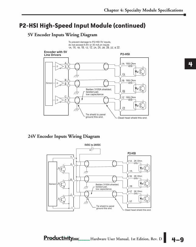
SureServo Wiring Diagram
SureStep Wiring Diagram
P2-HSO High-Speed Output Module (continued)
SureServo DriveP2-HSO
VDD
PULL HI
/PULSE
PULSE
COM–
/SIGN
SIGN
COM–
1A SNK
COM
1B SNK
COM
SHLD Tie shield to panel ground this end.
Belden 3105A shielded, twisted pair, low capacitance.
Dead head shield this end.
SureStep Driver #1P2-HSO
1A SNKCOM
1B SNKCOM
SHLD
2A SNKCOM
2B SNKCOM
STEP -STEP +DIR +DIR -
SureStep Driver #2
STEP -STEP +DIR +DIR -
Belden 3105A shielded, twisted pair, low capacitance.
Dead head shield this end.
Tie shield to panel ground this end only.
P2-HSO Pulse outputs rated 40 mA maximum
Pick ResistorV1 1/4W resistor24V, Use 2.2K ohm20V, Use 1.8K ohm15V, Use 1.2K ohm12V, Use 750 ohm10V, Use 560 ohm 5V, None required
V1
+

Chapter 4: Specialty Module Specifications
1
2
34
5
6
7
8
9
10
11
12
13
14
A
B
C
D
Hardware User Manual, 1st Edition, Rev. D4–18 2000
Sinking I/O Wiring Diagram
IN1+ 1A 1A 1BCOM COM SH SH1A
SNK1B
SNKOUT3SRC
OUT3SNK
OUT4SNK
OUT4SRC
OUT5SNK
OUT5SRC
IN1-
IN2+
IN2- 1B
COM COM OUT6SNK
OUT6SRC
2ASNK
2BSNK
PWR+
PWR-
IN3+
IN3-
IN4+
IN4-
IN5+
IN5-
IN6+
IN6- 2A 2A 2B 2B
1ASNK
IN3+
IN1+
IN4+ IN5+ IN6+
IN2+
PanelGND.
+
+24VDC5VDC
to24VDC
OUT5SNK
OUT6SNK
LOAD
OUT4SNK
OUT3SNK
LOAD
1BSNK
LOAD
2ASNK
LOAD
2BSNK
LOAD
LOAD
LOAD
LOAD
P2-HSO High-Speed Output Module (continued)

Chapter 4: Specialty Module Specifications
1
2
34
5
6
7
8
9
10
11
12
13
14
A
B
C
D
4–19 Hardware User Manual, 1st Edition, Rev. D2000
Sourcing I/O Wiring Diagram
IN3-
IN1-
IN4- IN5- IN6-
IN2-
+ + 24VDC
PanelGND.
5VDCto
24VDC
LOAD
OUT4SRC
OUT3SRC
OUT5SRC
OUT6SRC
LOAD
LOAD
LOAD
IN1+ 1A 1A 1BCOM COM SH SH1A
SNK1B
SNKOUT3SRC
OUT3SNK
OUT4SNK
OUT4SRC
OUT5SNK
OUT5SRC
IN1-
IN2+
IN2- 1B
COM COM OUT6SNK
OUT6SRC
2ASNK
2BSNK
PWR+
PWR-
IN3+
IN3-
IN4+
IN4-
IN5+
IN5-
IN6+
IN6- 2A 2A 2B 2B
P2-HSO High-Speed Output Module (continued)
Chapter 4: Specialty Module Specifications
1
2
34
5
6
7
8
9
10
11
12
13
14
A
B
C
D
Hardware User Manual, 1st Edition, Rev. D4–20 2000
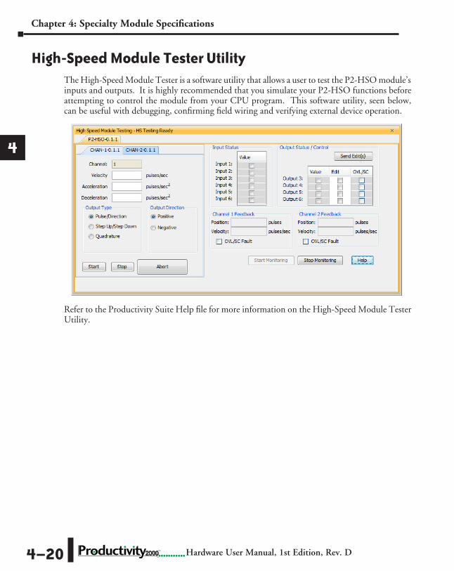
The High-Speed Module Tester is a software utility that allows a user to test the P2-HSO module’s inputs and outputs. It is highly recommended that you simulate your P2-HSO functions before attempting to control the module from your CPU program. This software utility, seen below, can be useful with debugging, confirming field wiring and verifying external device operation.
Refer to the Productivity Suite Help file for more information on the High-Speed Module Tester Utility.
High-Speed Module Tester Utility

Chapter 4: Specialty Module Specifications
1
2
34
5
6
7
8
9
10
11
12
13
14
A
B
C
D
4–21 Hardware User Manual, 1st Edition, Rev. D2000
The P2-SCM Serial Communications Module provides three RS-232 ports and one RS-485 port for Modbus master/slave networking or connection to serial devices using ASCII or custom communication protocols.
P2-SCM Module Overview
General SpecificationsModule Type IntelligentModules per Base 15 maximum (See Note)I/O Points Used None, mapped directly to tags in CPUField Wiring Connector 3 - RJ12, 1 - 4 Position Terminal BlockOperating Temperature 0º to 60ºC (32º to 140ºF)Storage Temperature -20º to 70ºC (-4º to 158ºF)Humidity 5 to 95% (non-condensing)Environmental Air No corrosive gases permittedVibration IEC 60068-2-6 (Test Fc)Shock IEC 60068-2-27 (Test Ea)Field to Logic Side Isolation None
Insulation Resistance No isolation
Agency Approvals UL508 File E139594, Canada & USA CE (EN61131-2007)
Module Location Any slot in any base in a Productivity2000 System
Weight 90g (3.2 oz)
Removable Terminal Block Specifications Number of Positions
4 Screw Terminals, 3.5 mm Pitch
Wire Range 16–28 AWGSolid/Stranded Conductor“Use copper conductors, 75°C or equivalent”
Screwdriver Size TW-SD-VSL-1 (recommended)Screw Torque 0.4 N·m
Removable Terminal Connector included. Spare connectors available, (part no. P3-RS485CON-1).
ULC USR
NOTE: For complete system limits, please refer to the “Hardware and Communication Limits” table in the Productivity Suite online “Help” file “Hardware Configuration”, topic P050.
Chapter 4: Specialty Module Specifications
1
2
34
5
6
7
8
9
10
11
12
13
14
A
B
C
D
Hardware User Manual, 1st Edition, Rev. D4–22 2000
P2-SCM Specifications, (continued)
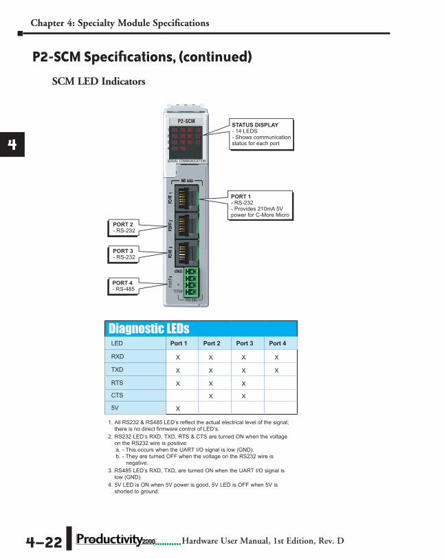
STATUS DISPLAY- 14 LEDS- Shows communicationstatus for each port
PORT 2- RS-232
PORT 3- RS-232
PORT 4- RS-485
PORT 1- RS-232- Provides 210mA 5V power for C-More Micro
Diagnostic LEDsLED Port 1 Port 2 Port 3 Port 4
RXD X X X X
TXD X X X X
RTS X X X
CTS X X
5V X
1. All RS232 & RS485 LED’s reflect the actual electrical level of the signal; there is no direct firmware control of LED’s.
2. RS232 LED’s RXD, TXD, RTS & CTS are turned ON when the voltage on the RS232 wire is positive: a. - This occurs when the UART I/O signal is low (GND).b. - They are turned OFF when the voltage on the RS232 wire is
negative.3. RS485 LED’s RXD, TXD, are turned ON when the UART I/O signal is
low (GND).4. 5V LED is ON when 5V power is good, 5V LED is OFF when 5V is
shorted to ground.
SCM LED Indicators
Chapter 4: Specialty Module Specifications
1
2
34
5
6
7
8
9
10
11
12
13
14
A
B
C
D
4–23 Hardware User Manual, 1st Edition, Rev. D2000
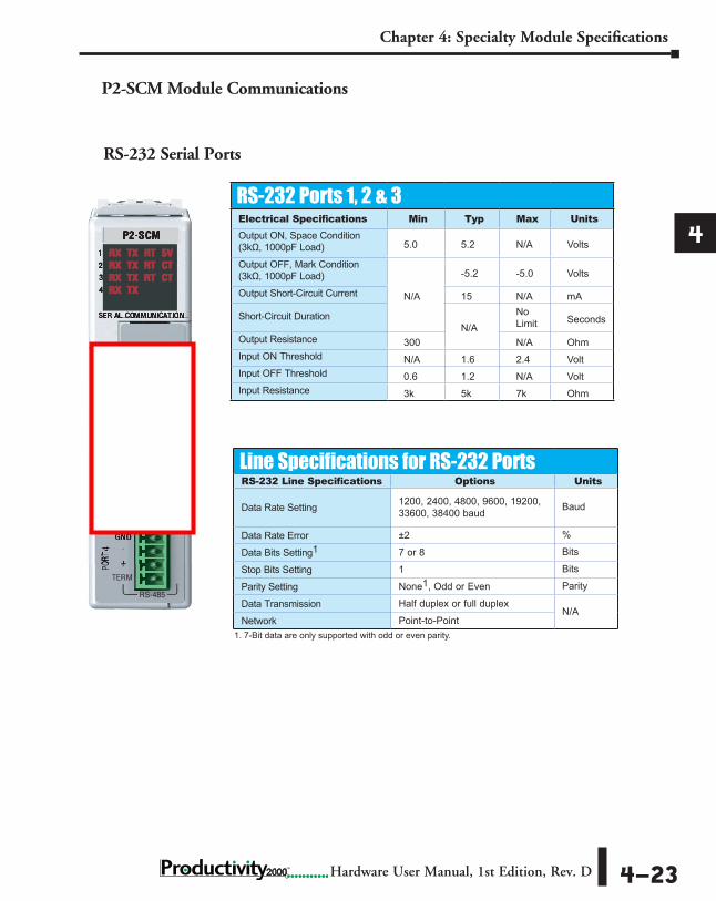
RS-232 Serial Ports
RS-232 Ports 1, 2 & 3Electrical Specifications Min Typ Max UnitsOutput ON, Space Condition (3kΩ, 1000pF Load) 5.0 5.2 N/A Volts
Output OFF, Mark Condition (3kΩ, 1000pF Load)
N/A
-5.2 -5.0 Volts
Output Short-Circuit Current 15 N/A mA
Short-Circuit DurationN/A
No Limit Seconds
Output Resistance 300 N/A OhmInput ON Threshold N/A 1.6 2.4 VoltInput OFF Threshold 0.6 1.2 N/A VoltInput Resistance 3k 5k 7k Ohm
Line Specifications for RS-232 PortsRS-232 Line Specifications Options Units
Data Rate Setting 1200, 2400, 4800, 9600, 19200, 33600, 38400 baud Baud
Data Rate Error ±2 %
Data Bits Setting1 7 or 8 Bits
Stop Bits Setting 1 Bits
Parity Setting None1, Odd or Even Parity
Data Transmission Half duplex or full duplexN/A
Network Point-to-Point
P2-SCM Module Communications
1. 7-Bit data are only supported with odd or even parity.

Chapter 4: Specialty Module Specifications
1
2
34
5
6
7
8
9
10
11
12
13
14
A
B
C
D
Hardware User Manual, 1st Edition, Rev. D4–24 2000
.
Port 1Port Type RS-232
Description
Non-isolated RS-232 DTE port connects the CPU as a Modbus/ASCII master or slave to a peripheral device. Includes ESD and built-in surge protection.
Data Rates Selectable, 1200, 2400, 4800, 9600, 19200, 33600, and 38400 baud
+5V Cable Power Source 210mA maximum at 5V, ±5%. Reverse polarity and overload protected
TXD RS-232 Transmit output
RX RS-232 Receive input
RTS Handshaking output for modem control
GND Logic groundMaximum Output Load (TXD/RTS) 3kΩ, 1000pF
Minimum Output Voltage Swing ±5V
Output Short Circuit Protection ±15mA
Port Status LED Red LED is illuminated when active for TXD, RXD and RTS
Cable Options
EA-MG-PGM-CBL D2-DSCBL USB-RS232 with D2-DSCBL FA-CABKIT FA-ISOCON for converting RS-232 to isolated RS-485
6-pin RJ12 FemaleModular Connector
6
1
6 GND Logic Ground 5 RTS RS-232 Output 4 TXD RS-232 Output 3 RXD RS-232 Input 2 +5V 210mA Maximum 1 GND Logic Ground
Pin # Signal
P2-SCM Module Communications (continued)
RS-232 Serial Port 1Non-isolated RS-232 DTE port connects the CPU as a MODBUS/ASCII master or slave to a peripheral device. Includes ESD and built-in surge protection

Chapter 4: Specialty Module Specifications
1
2
34
5
6
7
8
9
10
11
12
13
14
A
B
C
D
4–25 Hardware User Manual, 1st Edition, Rev. D2000
RS-232 Serial Port 2 and 3Non-isolated RS-232 DTE port connects the CPU as a MODBUS/ASCII master or slave to a peripheral device.
6-pin RJ12 FemaleModular Connector
6
1
6 GND Logic Ground 5 RTS RS-232 Output 4 TXD RS-232 Output 3 RXD RS-232 Input 2 +5V 210mA Maximum 1 GND Logic Ground
Pin # Signal
Port 2 and 3 Port Type RS-232
Description
Non-isolated RS-232 DTE port connects the CPU as a Modbus/ASCII master or slave to a peripheral device. Includes ESD and built-in surge protection.
Data Rates Selectable, 1200, 2400, 4800, 9600, 19200, 33600, and 38400 baud
TXD RS-232 Transmit output
RX RS-232 Receive input
RTS Handshaking output for modem control
GND Logic ground
Maximum Output Load (TXD/RTS) 3kΩ, 1000pF
Minimum Output Voltage Swing ±5V
Output Short Circuit Protection ±15mA
Port Status LED Red LED is illuminated when active for TXD, RXD and RTS
Cable Options
D2-DSCBL USB-RS232 with D2-DSCBL FA-CABKIT FA-ISOCON for converting RS-232 to isolated RS-485
P2-SCM Module Communications (continued)
Chapter 4: Specialty Module Specifications
1
2
34
5
6
7
8
9
10
11
12
13
14
A
B
C
D
Hardware User Manual, 1st Edition, Rev. D4–26 2000
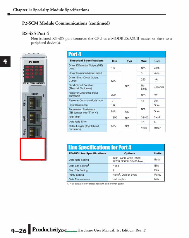
RS-485 Port 4Non-isolated RS-485 port connects the CPU as a MODBUS/ASCII master or slave to a peripheral device(s).
1. 7-bit data are only supported with odd or even parity
Port 4Electrical Specifications Min Typ Max Units
Driver Differential Output (54Ω Load) 1.5
N/A
N/A Volts
Driver Common-Mode Output
N/A
3 VoltsDriver Short-Circuit Output Current 250 mA
Short-Circuit Duration (Thermal Shutdown)
No Limit Seconds
Receiver Differential Input Threshold 200 N/A mV
Receiver Common-Mode Input -7 12 VoltInput Resistance 12k
N/AOhm
Termination Resistance (TB Jumper wire ‘T’ to ‘+’) N/A 120 Ohm
Data Rate 1200 N/A 38400 BaudData Rate Error
N/A N/A±2 %
Cable Length (38400 baud maximum) 1200 Meter
Line Specifications for Port 4RS-485 Line Specifications Options Units
Data Rate Setting 1200, 2400, 4800, 9600, 19200, 33600, 38400 baud Baud
Data Bits Setting1 7 or 8 Bits
Stop Bits Setting 1 Bits
Parity Setting None1, Odd or Even Parity
Data Transmission Half duplex N/A
P2-SCM Module Communications (continued)
1. 7-Bit data are only supported with odd or even parity.

Chapter 4: Specialty Module Specifications
1
2
34
5
6
7
8
9
10
11
12
13
14
A
B
C
D
4–27 Hardware User Manual, 1st Edition, Rev. D2000
RS-485 Port 4
Port 4Port Type RS-485
Description
Non-isolated RS-485 port connects the CPU as a Modbus/ASCII master or slave to a peripheral device. Includes ESD/EFT protection and automatic echo cancellation when transmitter is active.
Data Rates Selectable, 1200, 2400, 4800, 9600, 19200, 33600, 38400 baud
TXD+/RXD RS-485 transceiver high
TXD-/RXD- RS-485 transceiver low
GND Logic Ground
Input Impedance 19kΩ
Maximum Load 50 transceivers, 19kΩ each, 60Ω termination
Output Short Circuit Protection
±250mA, thermal shut-down protection
Electrostatic Discharge Protection ±8kV per IEC1000-4-2
Electrical Fast Transient Protection ±2kV per IEC1000-4-4
Minimum Differential Output Voltage 1.5 V with 60Ω load
Fail Safe Inputs Logic high input state if inputs are unconnected
Maximum Common Mode Voltage -7.5 V to 12.5 V
Port Status LED RED LED Illuminated when active for TXD and RXD
Cable Options L19827-xx
P2-SCM Module Communications (continued)
G-+T
Pin # Signal G GND – TXD-/RXD- + TXD+/RXD+ T TERMINATION
RS-485
Chapter 4: Specialty Module Specifications
1
2
34
5
6
7
8
9
10
11
12
13
14
A
B
C
D
Hardware User Manual, 1st Edition, Rev. D4–28 2000
Notes: