Embed Size (px)
Citation preview
SEA BOX, INC. S hipping and Storage Containers — Sales and Rentals Corporate Office
802 Industrial Highway — East Riverton NJ 08077 Tel (856) 303-1101 — Fax (856) 303-1501
www.seabox.com
STANDARD SPECIFICATION FOR
40' x 8' x 8'6"
GENERAL CARGO STEEL CONTAINERS
Effective Date 1 January 1999
W:/Specifications/11947 40x8x8.6 Specs
Sea Box, Inc. 40' x 8' x 8'6" Specifications
Issued: 01/01/00
CONTENTS
SECTION DESCRIPTION ISSUE DATE
1 Introduction 1 January 00
2 General Requirements 1 January 00
3 Dimensions and Weights 1 January 00
4 Materials 1 January 00
5 Construction 1 January 00
6 Surface Preparation and Coatings 1 January 00
7 Markings 1 January 00
8 Drawings 1 January 00
Sea Box, Inc. 40' x 8' x 8'6" Specifications, Section 1, Introduction
Issued: 01/01/00
Page 1
SECTION 1
INTRODUCTION This Specification provides the standard technical requirements for Sea Box general cargo steel containers. The configuration, material, features and expected performance specified in this document are the standard to which Sea Box purchases general cargo steel containers and are subject to confirmation prior to contract finalization. Manufacturers shall be responsible for notifying Sea Box, East Riverton, NJ of any item contained in this specification that requires further explanation or clarification. The manufacturer shall be held responsible for any determinations or assumptions made by him that result in the manufacture of a container that is not in accordance with this specification and not acceptable to Sea Box. The manufacturer shall remain responsible for the design and performance of equipment for the intended service, information provided herein notwithstanding. This specification is the property of Sea Box and contains information that is deemed to be confidential and/or proprietary. No use or disclosure is authorized except as permitted by Sea Box and its designated agent.
Sea Box, Inc. 40' x 8' x 8'6" Specifications, Section 2, General Requirements
Issued: 01/01/00
Page 2
SECTION 2 General Requirements
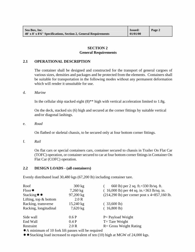
2.1 OPERATIONAL DESCRIPTION
The container shall be designed and constructed for the transport of general cargoes of various sizes, densities and packages and be protected from the elements. Containers shall be suitable for transportation in the following modes without any permanent deformation which will render it unsuitable for use.
d. Marine
In the cellular ship stacked eight (8)** high with vertical acceleration limited to 1.8g.
On the deck, stacked six (6) high and secured at the corner fittings by suitable vertical and/or diagonal lashings.
e. Road
On flatbed or skeletal chassis, to be secured only at four bottom corner fittings. f. Rail
On flat cars or special containers cars, container secured to chassis in Trailer On Flat Car (TOFC) operation, or container secured to car at four bottom corner fittings in Container On Flat Car (COFC) operation.
2.2 DESIGN LOADS - (all containers) Evenly distributed load 30,480 kgs (67,200 lb) including container tare. Roof 300 kg ( 660 lb) per 2 sq. ft.=330 lb/sq. ft. Floor 7,260 kg ( 16,000 lb) per 44 sq. in.=363 lb/sq. in. Stacking 97,200 kg (214,290 lb) per corner post x 4=857,160 lb. Lifting, top & bottom 2.0 R Racking, transverse 15,240 kg ( 33,600 lb) Racking, longitudinal 7,620 kg ( 16,800 lb) Side wall 0.6 P P= Payload Weight End Wall 0.4 P T= Tare Weight Restraint 2.0 R R= Gross Weight Rating
A minimum of 10 fork lift passes will be required Stacking load increased to equivalent of ten (10) high at MGW of 24,000 kgs.
Sea Box, Inc. 40' x 8' x 8'6" Specifications, Section 2, General Requirements
Issued: 01/01/00
Page 3
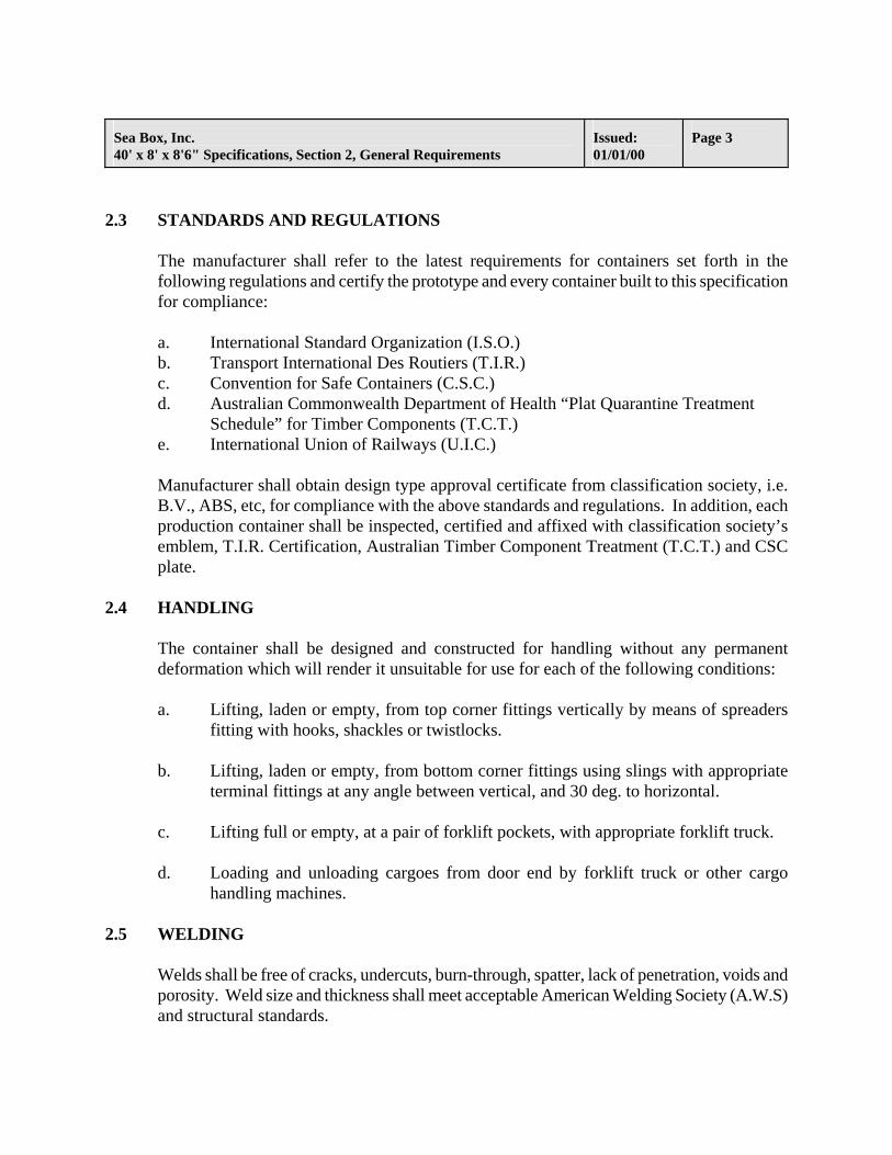
2.3 STANDARDS AND REGULATIONS
The manufacturer shall refer to the latest requirements for containers set forth in the following regulations and certify the prototype and every container built to this specification for compliance:
a. International Standard Organization (I.S.O.) b. Transport International Des Routiers (T.I.R.) c. Convention for Safe Containers (C.S.C.) d. Australian Commonwealth Department of Health “Plat Quarantine Treatment
Schedule” for Timber Components (T.C.T.) e. International Union of Railways (U.I.C.)
Manufacturer shall obtain design type approval certificate from classification society, i.e. B.V., ABS, etc, for compliance with the above standards and regulations. In addition, each production container shall be inspected, certified and affixed with classification society’s emblem, T.I.R. Certification, Australian Timber Component Treatment (T.C.T.) and CSC plate.
2.4 HANDLING
The container shall be designed and constructed for handling without any permanent deformation which will render it unsuitable for use for each of the following conditions:
a. Lifting, laden or empty, from top corner fittings vertically by means of spreaders
fitting with hooks, shackles or twistlocks.
b. Lifting, laden or empty, from bottom corner fittings using slings with appropriate terminal fittings at any angle between vertical, and 30 deg. to horizontal.
c. Lifting full or empty, at a pair of forklift pockets, with appropriate forklift truck.
d. Loading and unloading cargoes from door end by forklift truck or other cargo
handling machines. 2.5 WELDING
Welds shall be free of cracks, undercuts, burn-through, spatter, lack of penetration, voids and porosity. Weld size and thickness shall meet acceptable American Welding Society (A.W.S) and structural standards.
Sea Box, Inc. 40' x 8' x 8'6" Specifications, Section 2, General Requirements
Issued: 01/01/00
Page 4
2.6 PROTOTYPE
Unless agreed to otherwise, Sea Box shall require the manufacturer to construct in advance for inspection and tests a prototype container utilizing as many of the expected production components and manufacturing techniques as is then practical. Request by the manufacturer for waiver of prototype building and testing will only be considered if tests have been conducted previously on containers of the same design built for Sea Box.
2.7 PRODUCTION CHANGES
Changes in container design, construction or materials during the production run will not be permitted without the prior written approval of Sea Box, Technical Services Department in East Riverton. Unauthorized changes in the container design, construction, or materials, shall render the container unacceptable to Sea Box.
2.8 WARRANTY
The manufacturer shall warrant all structural components for two (2) years, surface preparation and paint protection for five (5) years, apitong plywood for three (3) years, other type of plywood i.e. combination plywood, etc. for five (5) years, and markings for seven (7) years. The manufacturer warrants to Sea Box that all containers and components thereof, delivered under this specification, shall comply with all requirements of this specification, shall be suitable for the purposes intended and shall be free from latent defects. Acceptance of containers by Sea Box shall not constitute a waiver of this warranty.
2.9 QUALITY CONTROL AND INSPECTION
Quality of containers manufactured under this specification shall be of consistent and uniform quality and in accordance with guidelines outlined in the I.S.O. standards 9000 through 9004, for quality management and assurance.
Manufacturer shall provide details on its quality control and inspection organization. This includes reporting function and a number of inspectors to be assigned for Sea Box production.
Sea Box shall inspect containers for acceptance at the manufacturer’s plant(s). Unless agreed to otherwise, no container shall be shipped without Sea Box’s acceptance. It should be understood that inspector has no authority to direct or agree to any changes in design, construction, or parts of the container.
Sea Box, Inc. 40' x 8' x 8'6" Specifications, Section 2, General Requirements
Issued: 01/01/00
Page 5
Samples, when requested, shall be provided to Sea Box which shall be tested to verify technical specifications and/or performance by an independent laboratory selected by Sea Box.
Approved for shipment by Sea Box inspector does not relieve the manufacturer of its responsibility that the container complies with the requirements of this specification, including warranty obligations.
2.10 RISK OF LOSS AND LIABILITY
All risk of physical loss or damage to any container supplied hereunder shall be the manufacturer’s responsibility until the container is delivered to Sea Box.
Manufacturer shall be insured for product liability in the United States.
2.11 DRAWINGS
The manufacturer is required to furnish to Sea Box at the time of quotation copies of his specifications including the following drawings.
a. General Arrangement b. Base Assembly c. Door Assembly d. Roof Assembly e. Front Assembly f. Side Assembly g. Marking Assembly
2.12 DEVIATIONS
The manufacturer may recommend alternate designs or deviations from Sea Box’s specification, by submitting (in advance) in a tabular format, a list of deviations at the time of quotation.
Deviation list must includes Sea Box specified item, alternate proposed, reasons for the alternate(s) and effect on price of container for each alternate.
No deviations will be permitted without prior approval from Sea Box.

Sea Box, Inc. 40' x 8' x 8'6" Specifications, Section 3, Dimensions and Weights
Issued: 01/01/00
Page 6
SECTION 3
DIMENSIONS AND WEIGHTS
3.1 GENERAL
The overall basic dimensions for dry van containers are set by the International Standard Organization (ISO). Other dimensions are specified by Sea Box.
3.2 DIMENSIONS
EXTERNAL (minimum)
Length 12,192 mm +0 -10 mm (40' 0" +0 - _") 480" Width 2,438 mm +0 - 5 mm ( 8' 0" +0 - 3/16") 96" Height 2,591 mm +0 - 5 mm ( 8' 6" +0 - 3/16") 102"
INTERNAL (minimum)
Length 12,027 mm (39' 5 ½") 473½” Width 2,350 mm ( 7' 8 ½") 92½” Height 2,384 mm ( 7' 9 _") 93_”
DOOR OPENING (minimum)
Width 2,340 mm ( 7' 8 _”) 92_” Height 2,276 mm ( 7' 5 _”) 89_”
CUBIC CAPACITY (minimum)
67.34 cubic meters (2,378 cubic feet)
3.3 WEIGHTS
Maximum Tare Weight 3,655 Kg ( 8,058 lbs) Minimum Payload 26,825 Kg (59,142 lbs) Maximum Gross Weight 30,480 Kg (67,200 lbs)
Sea Box, Inc. 40' x 8' x 8'6" Specifications, Section 4, Materials
Issued: 01/01/00
Page 7
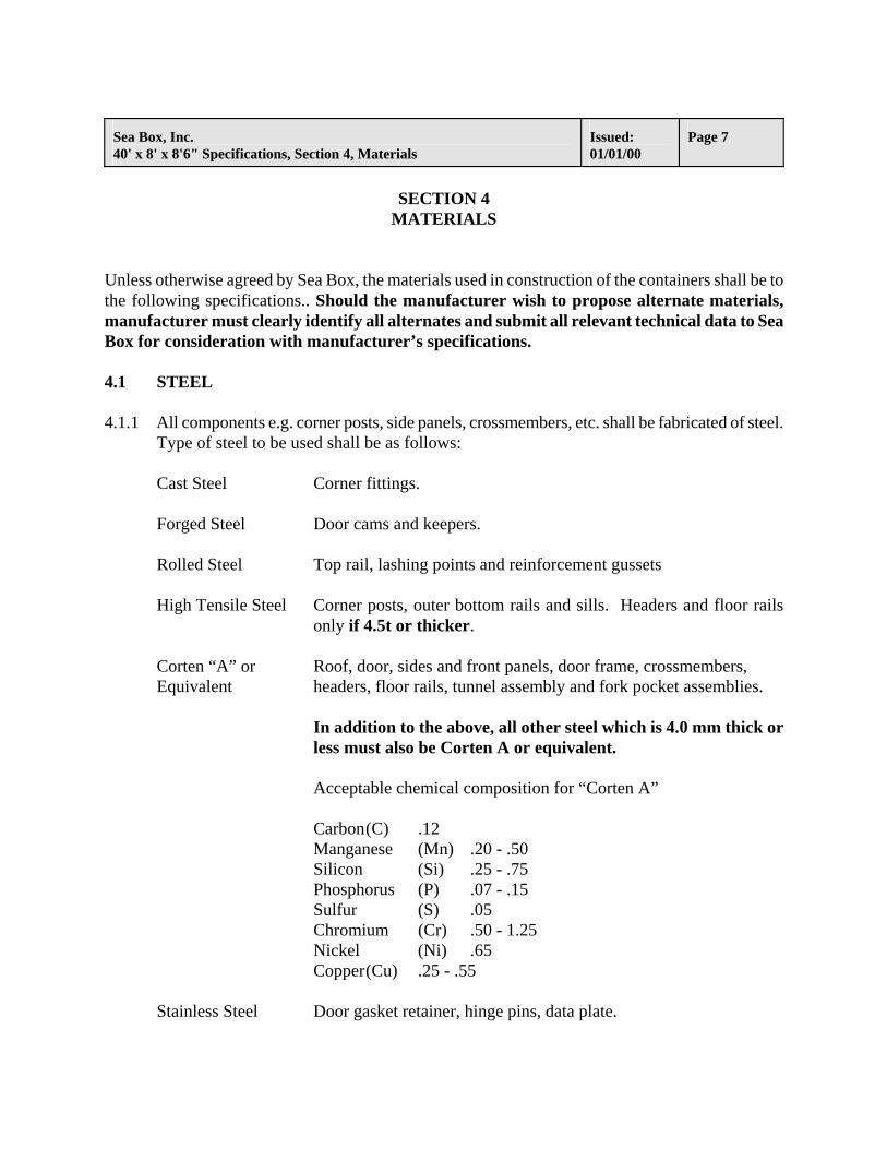
SECTION 4
MATERIALS Unless otherwise agreed by Sea Box, the materials used in construction of the containers shall be to the following specifications.. Should the manufacturer wish to propose alternate materials, manufacturer must clearly identify all alternates and submit all relevant technical data to Sea Box for consideration with manufacturer’s specifications. 4.1 STEEL 4.1.1 All components e.g. corner posts, side panels, crossmembers, etc. shall be fabricated of steel.
Type of steel to be used shall be as follows:
Cast Steel Corner fittings.
Forged Steel Door cams and keepers.
Rolled Steel Top rail, lashing points and reinforcement gussets
High Tensile Steel Corner posts, outer bottom rails and sills. Headers and floor rails only if 4.5t or thicker.
Corten “A” or Roof, door, sides and front panels, door frame, crossmembers, Equivalent headers, floor rails, tunnel assembly and fork pocket assemblies.
In addition to the above, all other steel which is 4.0 mm thick or less must also be Corten A or equivalent.
Acceptable chemical composition for “Corten A”
Carbon (C) .12 Manganese (Mn) .20 - .50 Silicon (Si) .25 - .75 Phosphorus (P) .07 - .15 Sulfur (S) .05 Chromium (Cr) .50 - 1.25 Nickel (Ni) .65 Copper (Cu) .25 - .55
Stainless Steel Door gasket retainer, hinge pins, data plate.
Sea Box, Inc. 40' x 8' x 8'6" Specifications, Section 4, Materials
Issued: 01/01/00
Page 8
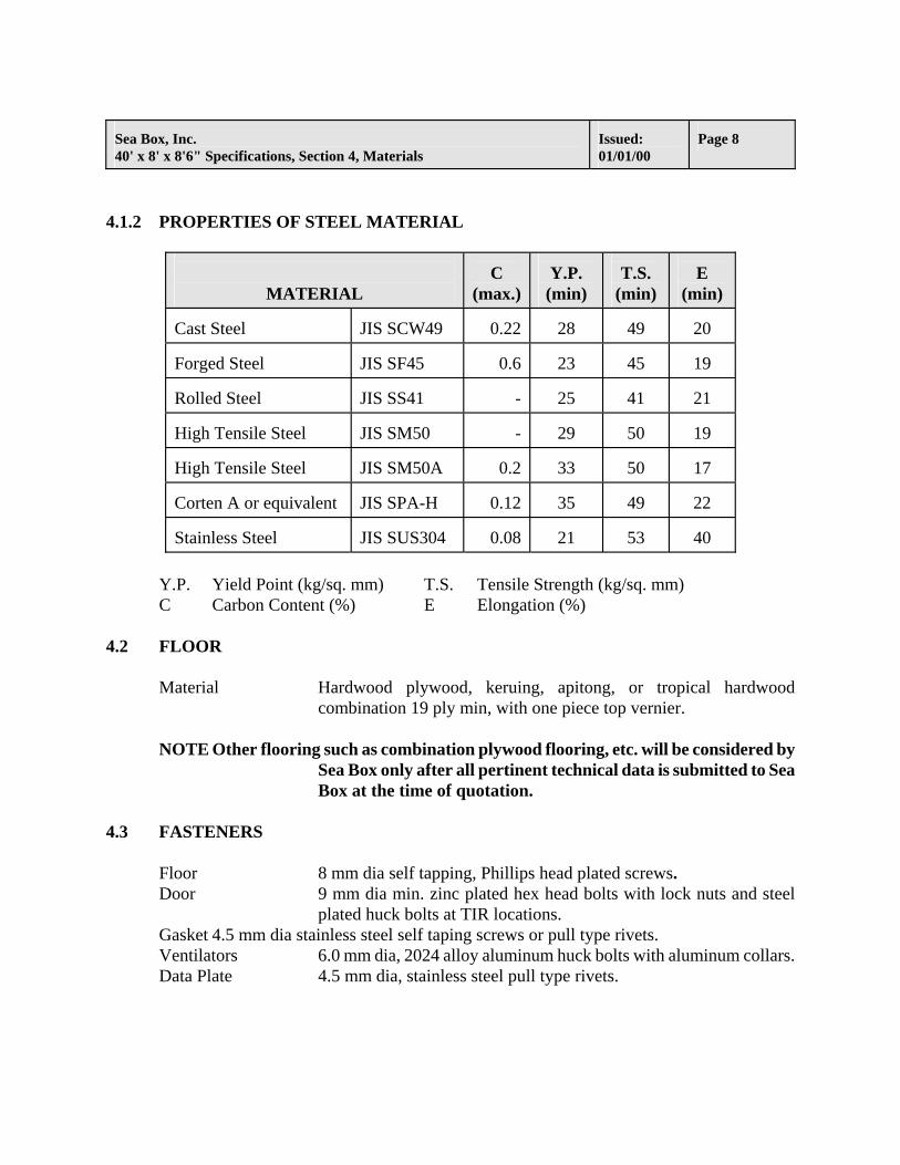
4.1.2 PROPERTIES OF STEEL MATERIAL
MATERIAL
C
(max.)
Y.P.
(min)
T.S.
(min)
E
(min) Cast Steel
JIS SCW49
0.22
28
49
20
Forged Steel
JIS SF45
0.6
23
45
19
Rolled Steel
JIS SS41
-
25
41
21
High Tensile Steel
JIS SM50
-
29
50
19
High Tensile Steel
JIS SM50A
0.2
33
50
17
Corten A or equivalent
JIS SPA-H
0.12
35
49
22
Stainless Steel
JIS SUS304
0.08
21
53
40
Y.P. Yield Point (kg/sq. mm) T.S. Tensile Strength (kg/sq. mm) C Carbon Content (%) E Elongation (%)
4.2 FLOOR
Material Hardwood plywood, keruing, apitong, or tropical hardwood combination 19 ply min, with one piece top vernier.
NOTE Other flooring such as combination plywood flooring, etc. will be considered by
Sea Box only after all pertinent technical data is submitted to Sea Box at the time of quotation.
4.3 FASTENERS
Floor 8 mm dia self tapping, Phillips head plated screws. Door 9 mm dia min. zinc plated hex head bolts with lock nuts and steel
plated huck bolts at TIR locations. Gasket 4.5 mm dia stainless steel self taping screws or pull type rivets. Ventilators 6.0 mm dia, 2024 alloy aluminum huck bolts with aluminum collars. Data Plate 4.5 mm dia, stainless steel pull type rivets.
Sea Box, Inc. 40' x 8' x 8'6" Specifications, Section 4, Materials
Issued: 01/01/00
Page 9
4.4 SEALANTS
Cargo area USDA approved chloroprene sealant to be used on interior seams which cargo may contact, such as but not limited to, roof to top rail, side panel to top rail, headers to roof and front panel, corner posts to front and side panels, all door interior seams and fasteners and the entire periphery of the floor on the interior of each container. Sealant must be compatible with interior coatings.
Other Areas Non-hardening butyl rubber or equivalent sealant, used between floor
lap joints and other seams which will not come in contact with cargo, such as all stitch and/or skip welds, any joint(s) which is not otherwise sealed by welding. Brown colored neoprene (or equivalent) sealant around vents, door gaskets and data plate.
4.5 MARKINGS
Decals Pigmented cast vinyl, color white. All markings shall be kiss-cut. Data Plate Stainless steel plate with etched on letters.
4.6 COATINGS
Primer Epoxy zinc rich, color gray, 90% min. zinc content. Intermediate coating Two pack epoxy, color light gray, RAL 7035. Exterior top Chlorinated rubber, color RAL 3009 (brown). Interior coating FDA compliant, two pack epoxy, color RAL 7042 (gray). Undercoat Tectyl 121-B.
4.7 GASKETS
Material Closed cell, EPDM rubber. Door Double lipped “J” section with modified “C” section lower gasket. Backing Strips Flat to match shape of door hardware mounting brackets. (door hardware)
4.8 VENTS
Material ABS plastic or equivalent. Color of vents to match top coat, i.e. RAL 3009 brown.
Geometry Labyrinth type with mounting gasket.
Sea Box, Inc. 40' x 8' x 8'6" Specifications, Section 5, Construction
Issued: 01/01/00
Page 10
SECTION 5
CONSTRUCTION Reference drawing 2SCV-01, 2SDV-02, 4S/4H-01, 4SDV-02, 4HDV-02, 2S/4S/4H-01 and SK-01 form an integral part of this specification and outline the requirements for construction. 5.1 BASE FRAME
Base frame shall comprise two bottom rails, crossmembers, and tunnel assembly on 40' containers.
Bottom Side Rail
Geometry Outer - formed channel section.
Inner - formed angle section. Gauge Outer - 4.5 mm; Inner - 3.2 mm. Assembly Inner rail stitch welded to outer rail. Features The end portion of each bottom rail shall be reinforced at the corner
casting area with one 9.0 mm thick doubler plate fully welded at each end of the rails and corner castings to eliminate damages to the bottom rails.
Crossmembers
Geometry Pressed channel section
40' container - 28 min. Gauge 4.0 mm minimum. Assembly Continuously welded to bottom side rails. Spacing for first
crossmember (from rear sill) must not exceed 300 mm from end of rear lower corner castings.
Tunnel (40' containers only)
Geometry One piece tunnel plate and rails. Plate reinforced from underneath by
bows. Gauge Tunnel - 4.0 mm minimum.
Bows - 4.0 mm Assembly Bows shall be stitch welded to tunnel plate. Sealant shall be applied
between stitch welding prior to undercoating.
Tunnel Outriggers (40' containers only)
Geometry Pressed channel section Gauge 4.0 mm minimum.

Assembly Continuously welded to bottom side rail and tunnel rail.
Sea Box, Inc. 40' x 8' x 8'6" Specifications, Section 5, Construction
Issued: 01/01/00
Page 11
Tunnel Bolster (40' containers only)
Geometry Box shaped member comprised to top plate and “U” shaped lower
section. Gauge 4.0 mm. Assembly Top and bottom sections continuously welded to form a subassembly.
Subassembly continuously welded to tunnel and rails.
Floor
Assembly Floor to be installed over crossmembers Thickness 28 mm. Assembly The floor planks shall be tightly fitted on the crossmembers. All
floor screws shall be countersunk below the surface of floor by 1.5 mm minimum. All the seams of each board and all the perimeters of the floor shall be sealed.
Treatment In accordance with Australian Health Departments regulations. Maximum moisture content shall not be over 12% before installation.
Floor Rail
Geometry Flat bar. Gauge 4.0 mm minimum Treatment Blasted primed and painted in the same manner as the crossmembers
. Lashing
Geometry Formed from 10 mm dia. bar welded to top and bottom side rails. Location 40' container - ten rings per top and bottom side rails. Features Rings shall have a pull strength of 1,500 kgs in any direction. Treatment Zinc plated.
5.2 FRONT END FRAME
Front end frame shall comprise of a header, sill, corner posts, front panel and corner castings welded together to form an assembly.
Corner Post
Geometry Single open “L” shaped pressing. Gauge 6.0 mm. Features Incorporating minimum three (3) 10.0 mm dia. zinc plated lashing
bars per post.
Sea Box, Inc. 40' x 8' x 8'6" Specifications, Section 5, Construction
Issued: 01/01/00
Page 12
Front Header
Geometry One piece open section with one doubler plate at each corner
casting. Gauge Header - 4.0 mm; Doubler Plates - 3.2 mm
Front Sill
Geometry “G” shaped section with three internal reinforcements. Gauge Sill - 4.0 mm; Gussets - 3.2 mm Features On 40' containers the lower portion of the front sill shall be
eliminated between the tunnel rails and the lower corner castings. The upper portion of the front sill shall be reinforced at the tunnel and casting areas with 9.0 mm thick, minimum, reinforcement gussets.
End Panel
Geometry Trapezium section corrugated 45.6 mm depth with pitch of 204 mm. Gauge 1.6 mm. Assembly Continuously welded externally to front end frame and internally to
corner posts. 5.3 REAR END FRAME
Frame shall be composed of corner posts, sill, header and corner castings which are welded to form an assembly.
Corner Post
Geometry Rectangular box section composed of outer and inner sections. Gauge 6.0 mm thick modified “C” section outer and 12.0 mm hot rolled
channel section inner. Assembly Continuously welded. Features Incorporating three (3) 10.0 mm dia. lashing bars per post. Lashing
bars to be zinc plated .
Rear Header
Geometry Rectangular box section fabricated from upper and lower sections with a doubler plate at each corner casting.
Gauge Upper, reinforcements and gussets 3.2 mm, lower - 4.0 mm. Features One reinforcement gusset welded behind each camkeeper.
Assembly Continuously welded.
Sea Box, Inc. 40' x 8' x 8'6" Specifications, Section 5, Construction
Issued: 01/01/00
Page 13
Rear Sill
Geometry Open section. Gauge Sill and reinforcements - 4.5 mm; Gussets 3.2 mm. Features One reinforcement gusset welded behind each camkeeper. Internal,
upper radius of sill to be 2 mm above level of floor. The lower portion of the sill shall be modified at the corner casting area to provide a recessed area to eliminate damages to the sill from chassis twistlocks.
Assembly Continuously welded. 5.4 DOOR AND HARDWARE
Doors shall be constructed with frame members and panel which are welded as a subassembly.
Door
Geometry Corrugated steel panel welded vertically to rectangular tubes and
horizontally to channels. Profile of door panel corrugations must be (Tokyu Car) open type to match the profile of side panel corrugations.
Gauge Panel - 1.6 mm Vertical tubes - 3.2 mm Horizontal channels - 3.2 mm
Features One locking T.I.R. plate to be fitted to outside of right door. Each door capable of swinging 270 degrees. Chloroprene sealant, color brown, is to be applied to the outer edges of lower gaskets to prevent water ingress. A nylon rope hold back shall be provided on each door.
Hinge Blade and Lug
Geometry Hinge blades shall be weld-constructed with boss and formed plate.
Hinge lugs shall be from pressed plate. Size Plate - 10 mm thick Features Each door shall be suspended by four hinges with nylon bushes and
stainless steel washer placed between the hinge and lug. Treatment Electro zinc plated.
Hinge Pin
Geometry 12.5 mm dia. bar.
Assembly Welded to the hinge lugs to meet T.I.R. requirements.
Sea Box, Inc. 40' x 8' x 8'6" Specifications, Section 5, Construction
Issued: 01/01/00
Page 14
Locking Assembly
Type Bloxwich B.E. 2566 with pressed handle. Geometry Two pronged type cams at each end. Size 34 mm outer diameter. Location Two locking bars per door. Features Cross over type handle positions. Assembly Bolted on doors with backing strips after painting of container. Treatment Hot dip galvanized.
Door Seal
Geometry “J” section with modified “C” section lower gasket. Features Continuous gaskets with vulcanized corner joints. Assembly Retained by stainless retainer and stainless steel fasteners. Gasket
to be fitted after final painting of container. 5.5 SIDE
Tope Side Rail
Geometry Flat bar. Size All containers - 14 mm thick x 50 wide.
Panel
Geometry 35 mm “tokyu car” profile. Gauge 1.6 mm thick panels throughout for 40' containers. Features No decal panels. Assembly Continuously welded to exterior of container frame. Sealant
caulking between interior stitch welding beads.
Ventilator
Geometry Small labyrinth type. Four (4) pieces for 40' containers secured with 6.0 mm dia. huck bolts.
Installation On each side at both ends of container on 40' containers, brown sealant to be applied on the sides and top of each ventilator.
Sea Box, Inc. 40' x 8' x 8'6" Specifications, Section 5, Construction
Issued: 01/01/00
Page 15
5.6 ROOF
Panel
Geometry 20 mm minimum depth corrugated panel with 3 large corrugations maximum per panel per attached drawing.
Gauge 2.0 mm. Features Roof panel shall be cambered 6 mm to 8 mm above at center to
ensure complete water drainage. Assembly Continuously welded.
Corner Protection (doubler) Plates
Geometry Rectangular plate as close to 400 mm x 400 mm as possible. Gauge 3.2 mm Assembly Continuously welded to roof panel and corner castings.
Sea Box, Inc. 40' x 8' x 8'6" Specifications, Section 6, Surface Preparation and Coatings
Issued: 01/01/00
Page 16
SECTION 6 SURFACE PREPARATION AND COATINGS
Sea Box places special emphasis on the quality of surface preparation and application of coatings, etc. Insufficient cleanliness, anchor pattern and/or improper application of coatings shall be sufficient cause for rejection of containers. Bearing this in mind, the manufacturer is requested to submit to Sea Box as much of the information as possible on coatings and coating application. Samples, when requested, shall be provided which shall be tested to verify technical specifications and/or performance by an independent laboratory selected by Sea Box. 6.1 GENERAL REQUIREMENTS
Coating dry film thickness (D.F.T.) shall be specified as minimum dry film thickness and shall be measured in accordance with the American Society for Testing and Materials, ASTM-D-1186-7, method of measuring dry paint thickness with magnetic gauges.
The method of surface preparation and the proposed abrasive type and size used shall be defined in advance and agreed by Sea Box.
The manufacturer shall identify the recommended paint supplier(s) and provide data sheets on the recommended coatings. Sea Box reserves the right to acceptance of proposed coatings.
6.2 SURFACE PREPARATION
The degree of rust in all pre-blasted steel shall not exceed the maximum allowable under ISO standard ISO 8501-1, rust grade A.
All oil, grease, labels, crayon, or other like contaminants shall be removed prior to grit blasting of steel surfaces and from painted surfaces prior to overcoating.
All steel surfaces shall be grit blasted (using steel grit) to a near white metal. An anchor pattern of 30 microns minimum and a maximum of 50 microns ( R max. 30-50 microns) shall be maintained. The pattern shall be uniform with a dense peak concentration with a minimum of 300 peaks per inch (300/25 mm). Surface shall be clean to Swedish standard condition of raw steel ASA 2 ½.
The blasted surfaces shall not be allowed to initiate re-rusting (flash rusting) prior to coating, i.e. max. 30 min.
Sea Box, Inc. 40' x 8' x 8'6" Specifications, Section 6, Surface Preparation and Coatings
Issued: 01/01/00
Page 17
After assembly of the container, all weld slag, surface contaminations, scars, etc., shall be removed by manual blasting or power wire brush cleaning to restore welds to condition suitable for application of the required coatings.
6.3 COATINGS
All painting shall be done in a workmanlike manner and the finished coating shall be free of dry spray, paint holidays, pinholes, bubbles, runs, drops, ridges, laps and variations in color, texture and gloss. All coats shall be applied in such a manner as to produce an even film of uniform thickness. Edges, corners, seams, joints, welds, rivets, and surface irregularities shall received special attention to insure adequate thickness of paint. Spray painting shall be supplemented with brush work where necessary to coat surfaces which may not be properly coated by spraying.
Paints and protective coatings shall be applied only under temperature and atmospheric conditions favorable to drying and which preclude condensations on surface to be painted. Application of coatings when the surface temperature is less than 5 degrees Fahrenheit (3°C) above the dew point will not be accepted. Sufficient time shall elapse between the application of successive coats to permit each coat to dry properly.
No repairs which will damage the paint system, i.e. welding, grinding, etc., shall be allowed after application of the top coating.
A. Designated Coating System
Outside Epoxy zinc rich primer Min. 30 microns
Epoxy intermediate coating Min. 30 microns Chlorinated rubber Min. 50 microns Total D.F.T. Min. 110 microns
Inside Epoxy zinc rich primer Min. 30 microns
Epoxy top coat Min. 40 microns Total D.F.T. Min. 70 microns
Underside Epoxy zinc rich primer Min. 30 microns
Tectyl 121 B Min. 220 microns Total D.F.T. Min. 250 microns
Sea Box, Inc. 40' x 8' x 8'6" Specifications, Section 6, Surface Preparation and Coatings
Issued: 01/01/00
Page 18
B. Alternate Coating System
Alternate coating systems are acceptable to Sea Box, only when all pertinent data such as paint supplier details, paint data sheets and application details are submitted (in advance) to Sea Box or at the time of quotation.
C Other
Hinge blades, hinge lugs, lashing rigs, lashing bars, camkeepers and fasteners such as bolts/nuts, washers, screws, etc., shall be electro zinc plated. Thickness: not less than 8 microns.
Locking rod assemblies shall be hot dipped galvanized after gear cams, bar, holder and handle hinges, have been welded as an assembly. Thickness: not less than 50 microns.
Sea Box, Inc. 40' x 8' x 8'6" Specifications, Section 7, Markings
Issued: 01/01/00
Page 19
SECTION 7 MARKINGS
7.1 GENERAL
The containers shall be marked in accordance with ISO requirements, owner’s marking specifications and other required regulations.
The consolidated data plate shall include all the pertinent information i.e., name of manufacturer and owner, timber treatment, CSC and TIR approval. All letters shall be engraved in permanent manner. In addition, the data plate shall be sealed with brown sealant on all sides except the bottom after plate has been affixed to the door panel.
7.2 DECAL APPLICATION
Decals must be applied after painting and drying. The adhered surface must be clean and smooth. All dirt and porosity should be removed between decal and adhered surface, prior to permanent decal installation.