Embed Size (px)
Citation preview

.S ARM K
0 ((~NVUATION
OCT 19
NTAL TE S
MILITARYZOTNILES
/ MODEL j55-B FIXED-ING INSTRUMENT TRAINER.
DA PROJECT NO. NONE
LNR, 1VIVUSAT=-C:: -- j 4 r-
Approved for public release; U S ARMYdistribution unlimited.
AVIATION TEST BOARD%Q -75-e;
FORT RUCKER, ALABAMA

DISCLAIMER NOTI
THIS DOCUMENT IS BEST
QUALITY AVAILABLE. THE COPY
FURNISHED TO DTIC CONTAINED
A SIGNIFICANT NUMBER OF
PAGES WHICH DO NOT
REPRODUCE LEGIBLY,

- COPY 1;"
DETAILED DESCRIPTION OF MODEL B55-B AIRPLANE AS TESTED
1. General. The Model B55-B airplane is a low-wing, all-metal,tricycle-landing gear, twin-engine airplane. Each IO-470-L enginedrives a 78-inch diameter, two-bladed, full-feathering, constant-speed2AF34C55/78FF-O propeller. The fuselage and tapered cantilever wingsare separate semimonocoque structures. The B55-B is certificated inthe Standard-Normal and Utility Category by the Federal Aviation Agency(FAA), and the Approved Type Certificate is 3A16. The manufacturer'sairplane serial nurnber is TC-663.
Z. Cockpit. Side-by-side seating is provided for the instructor pi-lot and student in individual, adjustable seats. Entrance to the ccckpitis gained by a side door located on the right side of the fuselage or fromthe cabin area. Rudder pedals and a wheel-type flight control are pro-vided for the instructor pilot and student. The instrument panel pro-vides space for engine and flight instruments, avionic control heads andindicators, and secondary electrical switches and circuit breakers. Apanel containing the magneto-starter, battery, and generator switchesIs located below the pilot's storm window. The fuel selector panel con-tains a fuel selector valve for each engine and a schematic diagram ofiuel flow. This panel is located in front of, and between, the instructorand student pilot's seats.
3. Cabin. Individual passenger seats are located in the cabin areabehind the instructor pilot's and student pilot's seat. The seats areforward facing, adjustable fore and aft, reclining chairs. Folding armrests are provided on the rear seats. Entry into the cabin is accom-plished through a side door located on the right side of the fuselage.The cabin has provisions for lighting, heating, and ventilation. The cab-iu. floors are carpeted and the walls and ceiling are fitted with sound-proofed appointments. The combined cockpit and cabin area has the fol-lowing dimensions:
Height - 50 inches (max.)
Width - 42 inches (max.)
Length - lOZ inches (max.)
Volume - 143 cu. ft. ,
1
%01V.,AT. TLa.U' <h
aimv.

4. Flight Controls. The B55-B airplane has r.ual flight cortr..isaffording cont-ol of the aircraft from either the instructor pilot or sti-dent pilot's station. A rotary movement of the control wheel determ'-.esthe aileron travel. Fore-and-aft movement cf the control cc1.lmn p; Bi-tions the elevator. The rudder travel is controlled by a dual set c- a -justable rudder pedals mounted on the cabin floor forward of the i.s :'c-tcr and student pilot's stations. The wing flap movement ig ele tr.c allycontrolled by positioning the flap control lever mounted on the engi:econtrol pedestal. The ailerons, elevators, and rudder are mechar.'::aflAactuated through push-pull rods and closed-circuit cable systems te:-minating in bell cranks. The aileron, elevator, and rudder trim-talcontrol wheels are located on the lower portion of the engine controlpedestal. Mechanical systems consisting Qf closed-circuit zables ar.jack shafts transmit trim control movements to the trim tabs. Iza-tors adjacent to the trim-tab control wheels show the trim-tab pos-ti, -.
The trim-tab control wheels are located with the axis of the vheel .7c.ir-cident with the maneuvering axis of the respective trim tab. Turnizig thaileron trim-tab control wheel clockwise gives a left wing-up att'e,and turning the wheel counterclockwise gives a right wing-up att'tu:e.A nose-up attitude is obtained by turning the elevator tr'm-ta. CZrtr Awheel downward, and turning the wheel upward gives a nose-:Iew-n atti-tude. Turning the rudder trim-tab control wheel to the left proVi&.-s aleft rudder trim, and turning the wheel to the right proides a -"ght z:-der trim.
5. Engine. The B55-B is powered by two 10-470-L engines. Th.IO-470-L is a direct-drive, wet-surnp, horizortally-opposed, ix-cyl.-der, air-cooled, fuel injection engine. The engine displacement is 471cubic inches, a.d the compression rau'o is 8. 6 to 1. The rated tak.. ffand rated maximum continuous brake hcrsepower is 260 at 2625 r. p.m.The FAA Type Certificate number for this engine is 3El. The oil capa-city is 12 quarts.
6. Engine Cowling. The engine cowling consists of five seCtions.To facilitate servicing the engine, a large cowl section on each side ofthe engine hinges downward. A cowling nose ring, a top cowl panel in-corporating the oil level indicator access, and the lower engine cowlcomplete the cowling assembly.
7. Engine Cooling. Cooling air enters the engine compartmentthrough the openings in the cowling nose ring. A down-draft ccolingsystem directs this cooling air down and around the engine cylinl.ersand out through the lower engine nacelle openings equipped with cowlflaps adjustable from the cockpit.
2
90c em sm-Gr IRL
8. Propellers. The Model B55-B is equipped with all-metal2AF34C55/78FF-O, controllable, full-feathering, constant-speed,tw)-bladed propellers. The propeller is controlled by a governormounted on the left forward side of the engine. Oil pressure actingon the blade-actuating piston changes the propeller blade angle to lowpitch. The propeller counterweights rotate the propeller blades to ahigh-pitch angl,. The governor regulates the oil pressure acti!.g agaInstthe counterweights to position the propeller blades for a constant rota-tional speed selected by the pilot. A combination of the centrifugal forceof the counterweights and force from an internal spring rotate the pro-peller blades to the feathered position when the oil pressure is relieved.A spring-loaded, high-pitch stop latch prevents the propeller from feath-ering when the airplane is on the ground and the engine is stopped. Thelatch is diser.gage- by *:entrif-igal force when the propeller is rotatingabove 500 r. p. m. Feathering the propeller is accomplished by movingthe cockpit pedestal-mounted propeller control lever rearward thzoughthe detent into the feathering range. Although unfeathering can be ac-complished in flight by starting the engine with the control lever justforward of the feathering detent, a positive unfeathering system is in-stalled to assist in the operation. This system consists of a nitrogen--harged accumulator, a special governor, and a hose running betweenthe governor and the accumulator. The governor contains a spring-loaded check valve which is unseated while the propeller control leveris in any position except "FEATHER," thus permitting governor-pres-s irized oil to flow ta and from the accumulator. When the propeller&.-ntrol lever is moved to the "FEATHER" position, the check valveis seated and oil under governor pressure is trapped in the accurmula-tor and hose. As the propeller control lever is moved out :f the"FEATHER" position, the trapped oil flows back through the governorto the propeller to unfeather it. The windmilling propeller makes itunnecessary to engage the starter for in-flight engine starting.
9. Fuel System. The fuel is contained in four rubberized bladder-type fuel cells, two located in each wing. The four cells have a totalusable fuel capacity of 142 US gallons. During normal operat'on eachengine draws fuel from the adjacent wing fuel cells. However, a systemof fuel cross-feed lines permits either engine to consume the entire fuelsupply of any or all cells. Each fuel cell is filled through its own filleropening located in the upper wing surface. The openings are covered byflush-type filler caps. An individual two-speed electric boost pump isprovided for each engine. High pressure is used for starting and providesfor near maximum engine performance should the engine-driven pump fail.When necessary in high ambient temperatures, low pressure can be usedfor ground operation, take-off, climb, and landing. The fuel on-off valvesare manually actuated from the cockpit by the fuel selector handles.
3
;14WAv U994UM,
Fut] quantity 's rneasurd by float-type transmitter units wh'ch tracs-mit signals to the fuel gauges on the instrument panel. A t%rc-pct *;.c.".selector swit:h, controlled by the pilot, determines the fuel cell, mainor auxiliary, to which each gauge is :onnected.
10. Landing Gear System. The Model B55-B airplane -s equippei.with an electrically-retractable tricycle ianting gear. The la:..iinggear is operated through push-pull tubes by a reversible electric mz &;.Zand actuator box under the front seat. The motor is controlled by arwo-position landing gear switch located on the right-hand s e %>f thepower control pedestal. Limit switches an! a dynamic braking systemautomatically stop the retraction mechanism when the landing gearreaches its full-up or full-down position. The nose gear retracts rear-ward into the .cs- s-i-ton. The main lar.d.Ing gear retra-ts -nwa-:.'.the wing wheel wells. Wlth the landing gear it, the UP --jpcostio t,
the wheels a-* -c-mpletely enclosed by fairing doors which are c.. _at'-.mechanically by the retraction and extension of the gear. n-i"'aup-locks actuated by the retraction system lock the main gear in the UPposition. No down locks are necessary since the over-center pivot ofthe linkage forms a geometric positive lock when the gear is fully ex-!knded. The linkage is spring loaded to the over-center position. Lar.-.rg gear position lights, located above the landing gear switzh, ir-'za~ ethe fully extended or retracted position. Additionally, a mechan-:al 4
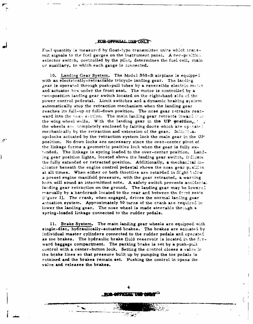
.cator beneath the engine control pedestal shows the nose gear p. s' '-nat all times. When either or both throttles are retarded in fl'ght .a preset engine manifold pressure, with the gear retracted, a warninghorn will sound an intermittent note. A safety switch prevents ac-'eztalarding gear retraction on the ground. The landing gear may be lower-zmanually by a handcrank located to the rear and between the f--nt seats(!;gure 1). The crank, when engaged, drives the normal larniing g6arartuation system. Approximately 50 turns of the crank are requi:!i .lower the landing gear. The nose wheel is made steerab.e through aspring-loaded linkage connected to the rudder pedals.
11. Brake System. The main landing gear wheels are equipped withsingle-disc, hydraulically-actuated brakes. The brakes are actuateti byindividual master cylinders connected to the rudder pedals ard ope.-atf.as toe brakes. The hydraulic brake fluid reservoir is located in the f-r-ward baggage compartment. The parking brake is set by a push-p%£1control with a center-button lock. Setting the control closes a Inal;, irthe brake lines so that pressure buit up by pumping the toe pedals isretained and the brakes remain set. Pushing the control in opens the;valve and releases the brakes.
4
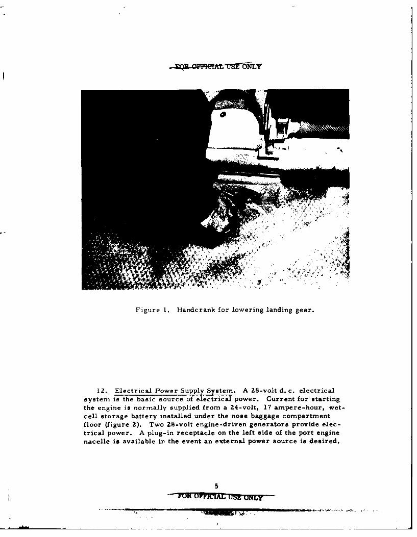
Figure 1. Handcrank for lowering landing gear.
12. Electrical Power Supply System. A 28-volt d.c. electricalsystem is the basic source of electrical power. Current for startingthe engine is normally supplied from a 24-volt, 17 ampere-hour, wet-cell storage battery installed under the nose baggage compartmentfloor (figure 2). Two 28-volt engine-driven generators provide elec-trical power. A plug-in receptacle on the left side of the port enginenacelle is available in the event an external power source is desired.
5"- Vi OIrWIiAL Usij um~y
6,E
Figure 2. Battery installation.
13. Heating and Ventilating System. A forced air heating and venti-lating system provides controllable cabin heat and ventilation. Blower
air is furnished until the aircraft is in flight and the landing gear is re-tracted, and then ram air replaces blower air. In addition to the air sup-plied to the cabin through the heater fresh-air system, a manually retract-
able air scoop on top of the cabin conducts outside air to individual freshair outlets above each seat. The outlets can be manually adjusted to con-trol the quantity and direction of air flow. A manually-controlled cabinair exhaust vent completes the air circulation system. A 50, 000-B. t. u.combustion-type heater provides heat for the cabin and the windshielddefroster.
6
i .. ..-

14. Basic Aircraft Data. (See fIgure 3 for general dimensions.)
Aircraft serial No. TC-633
Aircraft Type Certification No. 3Al6
Engine serial No. (Left) CS-91408-4L; (Right) CS-91409-4L
Engine Type Certification No. 3E
Areas.
Wing (total) 199. 2 sq. ft.
Flaps (total) 25. 7 sq. ft.
Ailerons (total) 11.4 sq. ft.
Tabs 3.1 sq. ft.
Horizontal tail (total) 48. 1 sq. ft.
Elevators (incl. tabs) 16.2 sq. ft.
Vertical tail (dncl. rudder) 22. 6 sq. ft.
Rudder (incl. tab) 11.6 sq. ft.
Dorsal fin 5.2 sq. ft.
General Data.
Wing
Airfoil section (root) NACA 23016.5
Airfoil section (tip) NACA 23010.5
Span 37 ft. 9.8 in.
Root chord 84 in.
Tip chord 35.64 in.
7
uvan'&ai Mm UU7
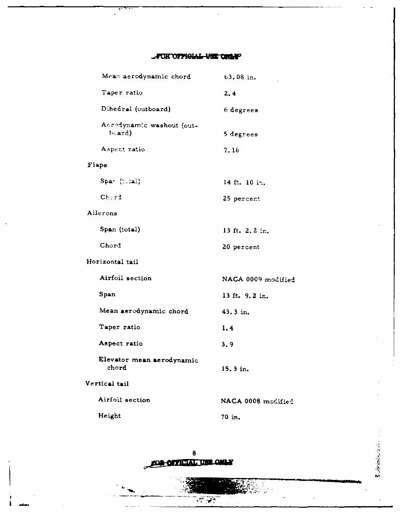
Mean aerodynamic chord b3. 08 in.
Taper ratio 2.4
Dihedral (outboard) 6 degrees
A'-r-Iynamic washout (out-bt ard) 5 degrees
Aspect ratio 7. 16
Flaps
Spar _ai 14 ft. 10 in.
C1:r- r1 25 percent
Ailerons
Span (total) 13 ft. 2. 2 in.
Chord 20 percent
Horizontal tail
Airfoil section NACA 0009 modified
Span 13 ft. 9. 2 in.
Mean aerodynamic chord 43. 3 in.
Taper ratio 1.4
Aspect ratio 3.9
Elevator mean aerodynamicchord 15. 3 in.
Vertical tail
Airfoil section NACA 0008 modeifiei
Height 70 in.
8

Height (ground line) 9 ft. 6 in.
Mean aerodynamic chord 58. 0 in.
Taper ratio 1. 9
Aspect ratio (geometric) 1. 2
Ru,7Aer mean aerodynamicchtrd 24.0 in.
Maximum fuselage area cross section
Height 5 ft. 4 in.
Width 3 ft. 10 ir.
Landing gear
Tread cf main wheels 9 ft. 7. 1 in.
Wheel base 7 ft. 0 In.
Clearances
Propell.r to fuselage 13. 5 in.
Propeller to ground (normalstatic position) 10. 4 in.
Propeller to ground (flat
struts and tires) 3. 75 in.
Fuselage to ground (flatstruits and tires) 16. 0 in.
Control surface movements
Wing flaps (maximum) 28 degrees down
Ailerons 20 degrees up
20 degrees down
9
. .... 'lllJ [ [ I I I~ l Ill I-- 'C."

m O Q RIC JALT IN:
Rudider 25 degrees right
25 degrees left
Elevator 30 degrees up
15 degrees down
10
MmA EEOL

THREE-VIEW DRAWING
- 1
___.......___ ___ .. . - -
Figure 3.General dimensions of. Model B55-B Airplane.
~+7ii
i i ."ir,'

CARBON MONOXIDE INVESTIGATION OF THE OFF-THE-SHELFFIXED WING INSTRUMENT TRAINERS
1. INTRODUCTION.
The US Army Aeromedical Research Unit was requested to determinethe carbon monoxide concentration within the crew/passenger compart-ment of the five Off-the-Shelf Fixed Wing Trainers.
The aircraft submitted for the evaluation were:
a. Aero Commander 500B.
b. Beechcraft Baron B-55-B.
c. Cessna 310"1".
d. Piper Aztec "B".
e. Piper Aztec "C".
2. METHODS AND MATERIALS.
a. Equipment used:
(1) Mine Safety Appliance Company Universal Testing Kit ModelZ with carbon monoxide detectors.
(2) A 250cc air sample was forced through a vial of carbon
monoxide sensitive crystals (part no. 471 34) using a manually operated"piston type" pump (part no. 83498). In the presence of carbon monox-ide, the normally pale yellow indicating crystals turn green. The con-centration of carbon monoxide is determined by comparing the color ol
the exposed vial to a standard color chart (part no. 994200). Sensitivityof the indicating crystals is .001 to 0. 101o carbon monoxide.
b. Method.
(1) Samples of the crew/passenger compartment air were col-lected while the aircraft operated at normal cruise with all vents closedand the heater on.
. . . .. . . . ...
(2) The air samples were collected at the heater duct
opening to readily detect the slightest amount of carbon monoxide.
3. RESULTS AND CONCLUSIONS.
No carbon monoxide was detected in any of the five aircraft
while operating at a cruise with all vents closed and the heater on.
, i 2
i ,~
.. ........ . i ~ l ~ l '.. " .. .. . . ... -- * ;. ,

F-=
UN lED SiA ES ARMY AVIATION TEST BOARDFert Rucker, Alabama 36362
FINAL REPORTOF
MILITARY POTENTIAL TESTOF THE
MODEL B5'-FB FIXED-WING INSTRUMENT TRAINER
DA PROJEC T NO. NONE
USATECOM PROJECT NO. 4-5-1001-01
A J. RAColonel, ArmorPresident
v g a"
Mm_ __€.' -" " -. .

PG~ WFTTAL ~4-NL- -
jagm, W...

A BST RACT
.~ Vt~ i1 ~rest of the Model B55-B Fixed-Wing Instru-
- t ~ ~ c ic-d '-'y the US Army Aviation Test Board during
pt~> 2S~- .~nL~: t .6 Oct'cber 1964 at Fort Rucker, Alabama.
1< V 'i r ~ i.J -Inra ated instrument conditions and demonstra-
* t.pt e'-~- - ~ti. g the US Army Aviation Center and the
4-ny A-i.; H c were conducted during the test period. It was
,-d + . M'. N f 135BFt(-tat1plaveas changed by the technical pro-
1 , ' i- f dtc r'eq,:rernerxts contained in the Model Specifica-
t -Ucr,'ni'fcr ded that a cc.nfirmatory test be performed on the
I -dc . i- .e if the Model B55-B airplane is selected as a
GoPY Doc~BL DOGOES NOTEMIT f ULLI LEGIBLE PIDGl~
ERIV
v
fA

OP0*99NUL UST (WTV-
T-.~ARMY AVIATION TES- BOARDFo~rt Rucker, Alabama
F 7NA 1,REPO-RT OF-I7R.- POTETh:AL TEST OF THE
Xi'I. ~.-b FXIEL)-WNG "1.STRTUMENT TRAINER
'Table o;f Ccn~ternt,
... ~ ~ ~ ~ ~ ~ -g .No. ......
.5. zit .-A c M-Aterie 1............ ......
DI I~73AND RES~jLTS OF S---B- TESTS . 5
C,- Ft.. ." 5
. .. . .C~± .~ . . . . .
* ~ ~ ~ ~ ~ . . .Cc~igza r.... .. . .. .. .. . ... 1
* with Mcde). Specifications.... .. . ....
COPY AVAILABLE TO DOC DOES NOTPERMIT FULLY LEGIBLE PRODUCTION
vi-- Jto uffiALux M CN
4-4,.
Aw.~

\ ED S I'-\ I ES ARMY AVIATION TEST BOARD
Vkri Ru,.1er, Alabama 3636Z
ITS'ASECOM PROJECT NO. 4-5-1001-01
REPORT OF MILITARY POTENTIAL TEST
OF THE MODEL B55-B
FIXED WING INSTRUMENT TRAINER
SEr TION I - GENERAL
1.1. REFERENCES.
A ist i_! references is contained in appendix I.
.g. Au rHOR'T j.
1.2 . 1. Directive?.
Letter.AMSTJE- t ¢-. US Army Test and Evaluation Command,I. er I164. -ab"'e, ': -lrest Directive for USATECOM Project No.
4 1001-01 MiIt-ar, Pental Test of Fixed-Wing Instrument Trainerr ralt."
*. 2. Pirpose.
Tro determine vhether the "off-the-shelf" Model B55-B airplane• i-llis Ihe Mcdel Specit' -:-. ns for fixed-wing instrument trainers
e ter en o 2).
i. ,. OH._3E rl'IVES.
Ti, determiie:
a. Specified ph .,--:al characteristics.
b. SpecLfied perf.,rmance.
Th,' adequacy #Af the electronics configuration as proposed.
(Or'Y AVAILABLE TO DOC DOES FEPERMIT FULLY LEGIBL_ PODUCTi56
lk1

1.4. RESPONSIBILITIES.
The US Army Aviation Test Board (USAAVNTBD, was responsiblefor developi:;g. preparing, and publishing the plan of test and the repor,
of test. Assistance during the test was pr, vided b, the US Army Avtat:. n
School (USAAVNS). Final approval of the plan and report of test i . the
responsibilt'v , I the US Army Aviation Materiel Command -USAAVCOM-.
1.5. DESCR!P TION OF MATERIEL.
The proposed Model B55-B instrument trainer airplane is a low
%king, all-mnctall, tricycle-landing gear. twin-engine airplane. The
fuselage and tapered cantilever wings are separate semimonocoque
structures. The aiV-pane is powered by two 10- 470-L direct drive.wet-sump. horizontally-opposed, six.-cylinder, a r.-co, led, fuei in-
jection engines. The rated takeoff and rated maximum contnuio, b. a.,
horsepower is 260 at 2625 r.p.m. Each engine drives a 78--inch dia
meter, two-bladed, full-feathering, constant- spe-d propeller. The pro-
pellt'rs are equipped with a blade unfeathering system. The cockpit pro-.
x des individual, adjustable, side-by--side seat- for the instructor arid
-tudent pilot. Individual forward-facing passenger seats are located inthe -abin area behind the instructor pilct's and student pilot's seat. the
fuel capacity is 120 US gallons. The grwss weight of the propcsed insttu-
ment trainer ;s 5100 pounds.
,.6. BACKGROUND.
1. 6. 1. In June 1962, the USAAVNS submitted to the Commanding
General, US Continental Army Command (USCON-A.RC;'. a requirement
;or a ommercially produced, 'off-the- shelf," fixed-.wing instrumenttrainer to replace the tactical airplanes presently used b, USAAVNS for
instrument training. In February 1963, the Director of Army Aviatio-,
Office, Deputy Chief of Staff for Operations (DCSOPS), submitted a State-
ment of Materiel Requirements to the Commanding General, US Army
Materiel Command (USAMC), for an "off-the.- shelf" fixed-wing instrument
trainer. A two-step procurement program was established. The Model
Specification, which was revised June 1964, accompanied the Request forTechnical Proposals (Step One for the Invitation for Bid) which %as pre-
pared by the USAAVCOM and mailed to industry 16 July 1964. Each
bidder was required to submit a written technical proposal and one unit
of the version of the aircraft on which it proposed to sabmit a bid. Fhe
Step Two of the competition will be confined to the bidders whose air.
planes and technical proposals are found acceptable. The second step
consists of a formal procurement in which bid pri( es will be submitted.
2
- ~I _'WT "
I - A.

1. ,. s. A M d.I B5- B t,-t airplane possessing a Federal Aviation-\A4en, V (FAA; Sta,idard- Nor mal and Utility Category Certificate was
d I'-, trred to 0h,, USAA'.NI BD for evaluation on 2 September 1964.
1 . 7. FIND! N -S.
The M, del 355.-B test airplane as changed by the technical pro-poual N, ill tit.. all .A the requirements contained in the Model Speci-If ation 'app,,Td9x
1. 8. CO"CLUSION.
Nore
1. '!. RECOMMRNDAT* ,ON.
it is e,, rnmended that a confirmatory test be performed onthe initial pr ,duICt-on airplane if the Model B55-B airplane is selectedas a fixed-wing instrument trainer.
3
.. ' , ; ..

. i t. ,LAILS AND RESULTS OF SUB-TESTS
I NIT1Oitl ( !.)N.
I. During rhe period 2 September 1964 to 26 October 1964, the\I deI B5-fl 'e,, tirplane underwent a 25- to 50-hour flight test pro-T? rfi ..)nducx'Ei h-, 'he , S Army Aviation Test Board (USAAVNTBD),
w - r Ri,( r. Alabania.
2 'I.gh' it dur a( -al and simulated instrument conditions and
.i ,hr derniristra' iots to pet onnel representing the US Army Aviation,r'er (L.SAAV N(. ard the US Army Aviation School (USAAVNS) were, ridit ted during 'he le ,. per jod.
1. Pt'YS.CAL C HIARAC r.ERISTICS.
2. t '. Obiective.
Fo de!.ermine -he physical characteristics of the Model B55-Bairplane as contained in paragraphs 1. 1. 1, 3.2 - 3.4, 3.6, 3. 7,
i . t. 1 1 of the Model Specification (appendix II).
. Methol.
1. 2. I. Tne phvical chara 'eristics listed in Model Specification
.paragraph 1. I. 1 ?.ere determined by visual study.
, 2. Deterrnirarion ot 'he physical characteristics listed in Model
tt, at in pdcdgraph ). 2, 1. 3, and 3.4 was made by measuring the, rplarie and weighrig it with lull oil and with fuel drained. Weight
.. b)aIance cornpu'aioris ,ere made for the proposed gross weight.
2 _ . The physical (haracteristics listed in Model Specification-..ragraph 3, t, were determined by visual and physical studies. Instru-
-,'rit patel cutouts were used to study the panel proposal.
;. .4. The requirements for interior and exterior lighting outlined., Model Specification paragraph 3. 7 were checked during night
:I. . he rotating beacon was checked for conformity with paragraph0.t, ( ,:1 Aer jrautics Manual 3.
5
''V.
2. 1. 2. 5. The heater was operated and an analytical study was madebased on the Model Specification requirement paragraph 3. 9. 1 andthe rated output of the heater.
2. 1. 2. 6. The aircraft furrished for the test was not equipped with de-icing and anti-icing equipment; therefore, a study was made from thedescription of the system in the FAA Approved Flight Manual andMaintenance Manual to determine conformity with the provisions ofModel Specification paragraph 3. 9. 2.
2. 1. 2. 7. Oxygen equipment was not provided with the test aircraft.A study was made of the descriptive material of the equipment foundin the FAA Approved Flight Manual and Maintenance Manual to deter-mine if the equipment offered in the technical proposal was capableof meeting Model Specification paragraph 3. 9. 3.
2. 1. 2.8. The area for stowage was measured and photographed todetermine whether the space provided met the provisions of ModelSpecification paragraph 3. 10.
2. 1. 2. 9. A study was made of the publications that accompanied thete.-,t aircraft to determine whether the requirements of Model Specifi-cation paragraph 3. 11 were met.
2. 1. 3. Results.
2, 1. 3. 1. General Description, paragraph 1. 1. 1, Model Specification:
2. 1. 3. 1. 1. The Model B55-B test airplane was equipped with individualside-by-side seating for a student and instructor pilot in the cockpit.Immediately to the rear in the cabin area, individual side-by-side seatswere provided for two students. (See figure 1.)
2. 1. 3. 1.2. Dual side-by-side flight controls were provided in thecockpit.
2. 1. 3. 1. 2. The Model B55-B test airplane was powered by two iO-470-Lreciprocating engines. Each engine drove a two-bladed, full-feathering,
constant-speed ZAF34C55/78 FF-O propeller. A positive propellerunfeathering system was incorporated. Moving the propeller controllever forward out of the feathering detent activated this system.
6
, <j --.I. ai_ _ -,., . - -

.... .i U .Z ....
q56
N /
~41b
Figure 1. Seating arrangement
2. 1. 3. 1. 4. The Model B55-B test airplane featured an all-metal semni-
monocoque construction and was Eqilipped with electrically retractable
tricycle landing gear.
2. 1. 3. 2. Paragraph 3. 2, Model Specification: The basic weight of the
test airplane was 3248 pounds. This weight did not include all of the
equipment required by paragraph 3. 1., and the electronic equipment listed
in appendix II of the Model Specification, which were not installed on the
test airplane. No deletions were made from the basic weight for items
installed on the test aircraft which were not required by the Model Specifi-
cation. The weight analysis in the technical proposal gave the basic
weight of the proposed aircraft as 3423 pounds. This figure could not
be substantiated due to the impossibility of obtaining exact weights of
all the items in question, and particularly for components permanently
installed.
7
F~R OTICL'r .j Y

-FOR-OnwimcTA uS!NLY~
2. 1 i. ;. Paragraph ; . Moldel S tpe in <at ion: 1 e (enter-of-gravity
( g. ) range was 82. in( hes (forward i g. limit) to 81. 5 inches (aftg. limit). No restrict ioni. to in sionn payload or utility arose from
tonstraints relating to the ( g. range.
2. 1. 3. 4. P-'aragraph 1. 4, Model Specification: In addition to fuel and
oil necessary to accomplish the endurance mission (5. 0 hours at 65%power at 7500 ft. MSI.), the useful load of the test airplane was 1087pounds. The technn al proposal presented a figure of 900 pounds ofuseful load for the proposed trainer.
2. 1. 3. 5. Paragraph . 6. 2 1, Model Specification: The Model B55-Btest airplane featured an all-metal semirmonocoque construction of theairframe.
2. 1. 3. 6. Paragraph 3. t 2 2, Model Specification: The cabin interiorarrangement provided individually adjustable side-by-side front seats.Two additional seats were provided immediately to the rear of the frontseats. The seating arrangement permitted the exchange of the seatingof the three students during flight. Shoulder harnesses were not pro-vided in the test airplane; however, the item was listed in the technicalproposal.
2. 1. 3. 7. Paragraph 3.6 2. 2. 1, Model Specification: The fire extin-guisher (4210-555-8837) and first-aid K it (9-196-650) are GovernmentFurnished Aircraft Equipment (GFAE) and, therefore, were not presenton the test aircraft.
2. 1. 3. 8. Paragraph 3 6, 2. 3. 1, Model Specification: The test air-plane was equipped with dual flight controls including rudder pedalswith toe-type brakes (figure 2). The rudder pedals were adjustable.
2. 1. 1. 9. Paragraph i ,,. 2. 2. Model Specification: The rudder,elevator, and aileron trii -tab (ontrol wheels were located in thelower portion of the engine ( ontrol pedestal. These controls werea(cessible to both the student and instructor pilot.
8

FOR OF"CIAL-U 9-ONLY
Uuo
Fig ire 2. Model B55-B dual flight controls
1 . I(). Paragraph 3. (, 2. 3. 3, Model Specification: The engine con-trol lever- vcre n mount ed on the engine control pedestal located in front
of, and betv, een, the stident and instructor pilot. The engine controllev( r-, c ,nt rolled the thrt tc, propeller, and fuel mixture. A largefriction lo ck knob on the ongine control pedestal locked the engine con-Irid levers in any desired position. These control levers were easily,CC(-S'Ible to the studerit and instructor pilot.
2 1. . ! I r. P;trt.raph i. t, 2 . 4. Model Specification: A positive three-ax;-; (,ntrol rt;( e 1oci which could be installed on the flight control
(r d i' o r ;.k I . kIs provided with the test aircraft.
'-PR 7!CTrUSZO~qL

FORX3FF-hTAL, TJE ONLY
flut conftrr 1, the provisimr. ! 111f. Sim"~ tial )oil The in trul-
ment pancl lt t ribed in lti t., hi ;il :'r i-. t i d the prop)er arrange-mentfl of ins.trinitrnts. 'Flic t%,,% ~1- tt:11idc inUliators had sep~arate
powver swirt es!
2. 1., 5. 13. 1 atra graph i. L).? 2 .. Z, (\td c I'-'p to t Ii on: Ihe 1 roposed
engine instrumrents wvere re-adable by hoth l tudenit and instruictor pilot
0(1 zr e
1'0K nrFItebL USE NL

1 . 14. Paragraph i 7. I. Model Specification: All of the instru-mnents on the test aircraft were individually lighted, and were c:on%-
patible with night and instrument flight rule operations. A secondarylighting system consisting of red panel flood lights was located in theoverhead panel. The intensity of the flood lights was controlled by arheostat control knob. Cabin illumination was furnished by a white
dome light located in the overhead panel. This light was controlledby av: "ON-OFF" switch beside the light.
2. 1. . 15. Paragraph 1. 7. 2. Model Specification: The Model B55-Btest airplane was equipped with a rotating anticollision beacon fairedinto the top edge of the vertical stabilizer. The installed beacon met
the provisions of the FAA requirements as set forth in paragraph 3. 705of the Civil Aeronautics Manual 3.
2.1.3. 16. Paragraph 3.9. 1, Model Specification: A 50, 000-B. t. u.combustion-type cabin heater was installed in the test airplane. Existing
climatic conditions precluded actual tests to determine the capability ofthe heater to meet the criteria of the Model Specification. However,using the ventilating air flow rate stated in the aircraft maintenancemanual and available combustion heater information (reference 4), the
installed heater should amply fill the requirements of the Model Specifi-
cation.
2. 1. 3. 17. Paragraph 3.9. 2, Model Specification: The Model B55-B
test airplane was not equipped with wing deicing and propeller anti-icingequipment. The technical proposal stated that pneumatic deicer bootsfor the wing and tail surfaces, operated by engine-driven pumps, and
alcohol propeller anti-icing equipment were available. The ModelB55- B airplane had FAA approval for installation of inflation type wingand empennage deicer boots and alcohol propeller anti-icers.
11
a. .a.* s -- j S . ... .. ;
Tr,
,C

k ~ ~ ratif
tit C
-7 ''17

2 - .i)df.' SI w >- (ification: T~he
I ' p t t I)!, ;t iiin i -i 11 of 1 00
l~mfA t' it. A gc g -iipartlflent in thle nose section
=r,:: .1 '1cl I- uic feet 01 baggage space (figure 4) and
ai~, ti-a \-t ight limit of 270 pounds. A door 2 1. 0 inches
I Ide by I ' in( ll ,: 11ii1 Iipu' ed access to the baggage compartmentirorn th, -iots(idc 'I ivre was arnple storage space within the cabin for
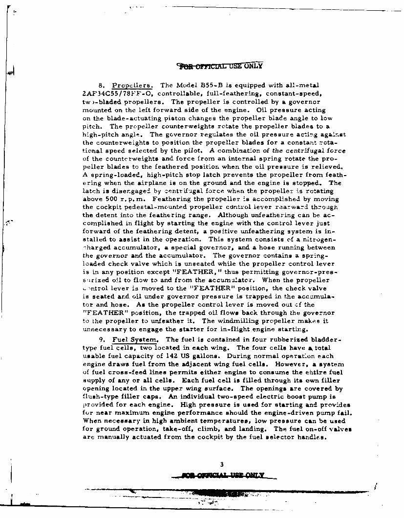
mnaps .. hr, (,fat r and one TM 1 1-2557 (Jeppesen Case). AtowaL-'r al' I 1m hd Ht rcar seat mnea sured 39 inches wide (average),
44 irn( .-.. V (avmcragt ), and io inches long (figure 5). The weight
capa( i% of Oi: a r.;i wA. pla arded for a weight limit of 400 pounds.OUtid( t(~ is, tt this area was by a side baggage door which measured
221. 5 :I hc ide and 16. 5 inches high (figure 6).
-Ii
i" .ot(\Vi2 abhru rear seat
1TlGFI!A . '.

Figure 6. Access by side baggage door.
2. 1. 3. 20. Paragraph 3. 1 1, Model Specification: The Model B55-B
test airplane was delivered with an FAA-approved airplane nlightm-anual and a maintenance and parts manual.
2. 1. 4. Analysis.
No~t tpph a hi.
14
UM~ OFCIAL UWITMuiit

2.2. PERFORMANCE.
2.2. 1. Objective.
To determine the performance characteristics of the ModelB55-B test airplane as related to the requirements specified in para-graph 3. 5 of the Model Specifications.
2. 2. 2. Method.
2.2. Z. 1. The test airplane was flown at the gross weight outlined bythe useful load requirement (paragraph 3.4, Model Specification), andtests were conducted to determine the cruise true airspeed (TAS),endurance single-engine service ceiling (FAA requirement), and mini-mum sale single-engine speed (Vmc). Ballast was used to bring thegross weight of the test airplane up to the Standard-Utility Categorygross weight of 5100 pounds. Data were tabulated in the National Aero-nautical Space Administration Standard Day format.
2. 2. 2. 2. The airspeed indicator from the test aircraft was calibrated.
The airspeed position errors were obtained by the ground speed coursemethod outlined in reference 3.
2. 2. 2. 3. The factory engine cruise control chart and procedures out-lrined in the flight manual were used to determine the power settingsfor a series of stabilized level flight, 65-percent, cruise power runs.The data recorded were corrected to standard-day conditions.
10-
2. 2. 2. 4. The endurance data were obtained by use of the installedflow meters and verified by controlled flight profiles. The power wasin accordance with recommended power charts and procedures. Themixture controls were set for best economy.
2.2. 2. 5. The single-engine service ceiling was determined by a seriesof saw-tooth climbs to substantiate the factory-recommended single-engine climb schedule. Using the climb schedule, climb data were ob-tained and reduced to standard-day conditions.
2. 2.2. 6. The minimum safe single-engine speed was investigatedusing the procedures and conditions described in paragraph 3. 111,
Civil Aeronautics Manual 3 (reference 5).
15
........ .........- - -, - ------- - ----
77...
7-7
.~~ .. .- -. .
-~. ..- - ......... .......... .
... . ...... h~ .4~ ' W_
.... .. . . ... .. -
L L ~ . ~ t - - -. - -4
.. .. . .. 6
2. 3. Reo.
2.2. 1. 1. rh,' , - ' sp,..d al 65 por ent power, 7500 feet mean sea
lt,,!l \kas 187.8 k, t- I kS.
2.2. 1.2. Fhe t ,1,,,! BN'5 B ',ts, airplane consumed an average of
24. 0 gallons t,, I i .: h. . -it '500 feet altitude using a 65-percent
(t"; eccoromy7 , f z' ,, ,. -'ltinng. The test airplane basic weight
i , 3248 ptunds. W i'h the engine oil (45 pounds) and the 900-pound
n.,etul load req itred . th- \4odJl Spec ification, 907 pounds of fuel
I 1. I galh,,i' i rn-i e d l-d t, neet the Standard-Utility Category
-. .. s \keiht ol lij() p. ind-,. With this quantity of fuel, the test air-
tlaye w.l1 .,erate at the roe. rhbed altitude and power settings fort. 28 hour s. Hov t-,'e! the I - hni al pru, pesal basic weight of 3423
i ,,ndb tr the ii,, k'ne-,t raci.er will allow 720 pounds (1Z0 gallons)r fiel. Thi- q.i-an':, . - :.l , ill give the proposed instrument
'raner an endi a,., I ti !' ". 0 hours based on the fuel consurnp-
,* - ,ate (,f the tt's d ,t plan,- engines.
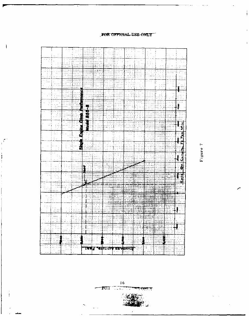
".2. i. 3. liH NI, -dr 'e-, airplane had a single-engine servicetl:t . ib h 1 t ,. i , W . .n. 1 7800 feet (see figure 7).
2. . 4. The m ',mti i A ft- single engine speed (Vmc) at sea level
A': ant A I - d ati j sp)ee#-d -'CAS).
S .4. A, al - .
No~t appl, iW..
i. ELECTFRO , CPA t r ,,URATON.
3 . . 1. Obje( It -c.
To htidN th,- 'I ei,'. al pi tp, sal arid determine the adequacyI the elettroni( s inf 1,ar at urn as related to paragraph 3.8 of the
', ,del Spec ificat ,.
4. ,.2. Method.
. .Z. 1. The levt hn -I prt to, al w.as stud'ed with regard to electronic
.qwprnent as .i-ted n abpendx 11 Model Specification. Where prac-to, al the installalit,,i plAjni- - f the above items were studied.
COPY AVAILABLE TO DOC DOES NOT17PERWIT FULLY LEGIBLE PRODUCTION
' e dmc u tW'-

2. 2.2. Cardboard cutouts were installed to check accessibility and
readability of the ele(tronic controls.
2. 1. 2. 3. A study was made to as(ertain the conformity of the elec-
trnic control locations with paragraph 3.8. 3, Model Specification.
2. 5. 3. Results.
2. 3. 3. 1. Paragraph 3.8. 1, Model Specification: The electronic con-
figuration proposed for the instrument trainer was in accordance with
appendix II, Model Specification.
2. 1. 3.2. Paragraph 3.8.2, Model Specification: The electronic , on-
trols were easily accessible and readable to the student and instructor
pilot (see figure 3).
2. 3. 3. 3. Paragraph 3.8. 3, Model Specification: The electronic con-
trols proposed were front panel mounted. No overhead control panel
installation was proposed.
Z.3.4. Analysis.
Not applicable.
18
!, Cw

SECTION 3
APPENDICES
19

APPENDIX I
LIST OF REFERENCES
1. Plan kt f Test, USATECOM Project No. 4-5-1001-01, "MilitaryPotential Test of 'Off.-the-Shelf' Airplanes as Fixed Wing InstrumentTrainers," USAAVNTBD, date 18 November 1964.
2. Le~ter, AMSTE-BCT, USATECOM, 29 October 1964, subject:"Military Potential Test of Fixed Wing Instrument Trainer Aircraft,
-kith inclosurtvs.
3. AF-TR-6273, Flight Test Engineering Manual, Major RusselM. Herrington and Captain Paul E. Shoemacher, May 1951, (revisedJanuary 1953).
4. Kent's Mechanical Engineering Handbook (Power), Revised 1957.
5. Civil Aeronautics Manual 3, Airplane Airworthiness, Normal,'t illy. and Acrobatic Categories, May 1962.
6. B55 Owner's Manual, Beech Aircraft Corporation, 20 September
7. B55 Shop Manual, Beech Aircraft Corporation, 20 September
9. Model Specification, Fixed Wing instrument Trainer, Revised', me 1964, with Flight Instrumentation Appendix I and Table E,
Appendix II.
9. Letter, SMOSM-PAIF-1, USAAVCOM, 16 July 1964, subject:",,-itation for Bid No. AMC(T)-23-204-64-459 (Step One)."
10. Technical Proposal, Beech Aircraft Corporation, 20 August 1964.
1-1
| a m .... ..

APPENDIX II
COMPARISON WITH MODEL SPECIFICATIONS
Proposed
Model B55-BTrainerAirplane
Meets Mod
Model Specification Specs Remarks
Fixed-Wing Instrument Trainer
1. SCOPE
I. I Scope. This specification
covers the essential requirementsfor an instrument training airplanecapable of pertorming the missions
sipecified in 1. 2.
1. 1. 1 Designation and GeneralDe ac cr iption
Army Model Not yet
Designation assigned
Number of I Pilot Yes
Crew (instructor)
Number of 3 Students Yes
Passengers
Flight Dual, side Yes
Controls by side
Propulsion Two recipro- Yes
cating engines,feathering andpositive un-
feathering
propellers
II-I

FOR OFICAL USE oNLY
Proposed
Model B55-B
Trainer
AirplaneMeets Mod
Mcdel Spec iftic: Specs Remark.;
Co'fig-aii All metal Yes
ticn ar d with retract-
Ccnstructi,,n able tricycle
landing gear
.2 MI "3- " . F lay inssic-iin, which tbl ii-: ...... b emit-,W17ETT ., l;Pla.e ",,ill be ern-
preyed is the trairi'ig of militarypilots in, u trunerit flying, in both
day and night instrument flight ruleoperatior-.
1.2. 1 1,eco ..d,ry Mi -sion. Twin
tiigine Trmts.tion Trainer for single,-:gire rated -jaiatcrs.
1. i Performance 1,rformation.I , _ e itorns (J perfo-rmance statedI reqtirernent3 herein which are
,o t h!.cluded irn the FAA approvedf t .mar ual !re --utject to
,ri'ication by the U. S. Army.
APPLICABLE DOCUMENTS
. 1 The applicable documents shallbe thcse necessary to fulfill the re-
quirements of paragraph 3. 10,Federal Aviation Agency Gertifica-
tmion.
3. REQUIREMENTS
. Federal Aviation Agency Yes
C-rtification. The airplane shallhave a Part 3 (effective as of the
UM-
...... .LU~5u~

UI OFTQF'IC1AL USE ONLV
Proposed
Model B55-BTrainerAirplaneMeet-; Mod
M,,del SpectitcP tiort Specs Remarks
d. ,t ,I .. t the fFB) stand-,rd airwkr!,iric -( certificate for
instrir ei t ii gi-t oper-tio:ns. issued
by the F( d( r:,I.Aviation Agency inthe i.!ti itV c!tegr V.
GFAE (c! ct-r(.ic ', c,.-tractor Yes,"-t l[ II ,uil be ,pe:'atiorally
verified I, I. \A.
.2 B;1 si, Weight. The basic Ye_ Basic weight
NV(e. ht tt "c ,iirpLane shall include of test airplane.il req tir, d iitjlled equipment did not include
r! id:u-g tie iteln- ir Section 3. 9 required in-
.d the Liectri -ic Equipment as stalled equip-, ipj idix i. ment.
( C i r. - Cr -vity Ra,ge. No Ye,
, t r ., payload or,riI ity, ha ri e ir,,m cc,nstraintsr, La1ti: g h. ce, ter--f-gravity range,
i .ti-cri i at, lcading not to
.Ct(d u ,eluL I tA.
.4 T fefu! L-,id. The dseful load Yes
1be a rnirnrflum of 900 !bs. of
pavl -,ad i'. addition to fuel and oilr ece-sary Ik, acec,impii, h the endur-trce rni i n of paragraph 3. 5. 1.
Requireci Perfcr;nance
I CAO Standard Da, Per-
firtifi :tfd gr,!as weight)
11-3
Proposed
Model 1355-B
TrainerAirplaneMeets mod
Mo(del Spec' fic .).t i'r Specs Rernarksi
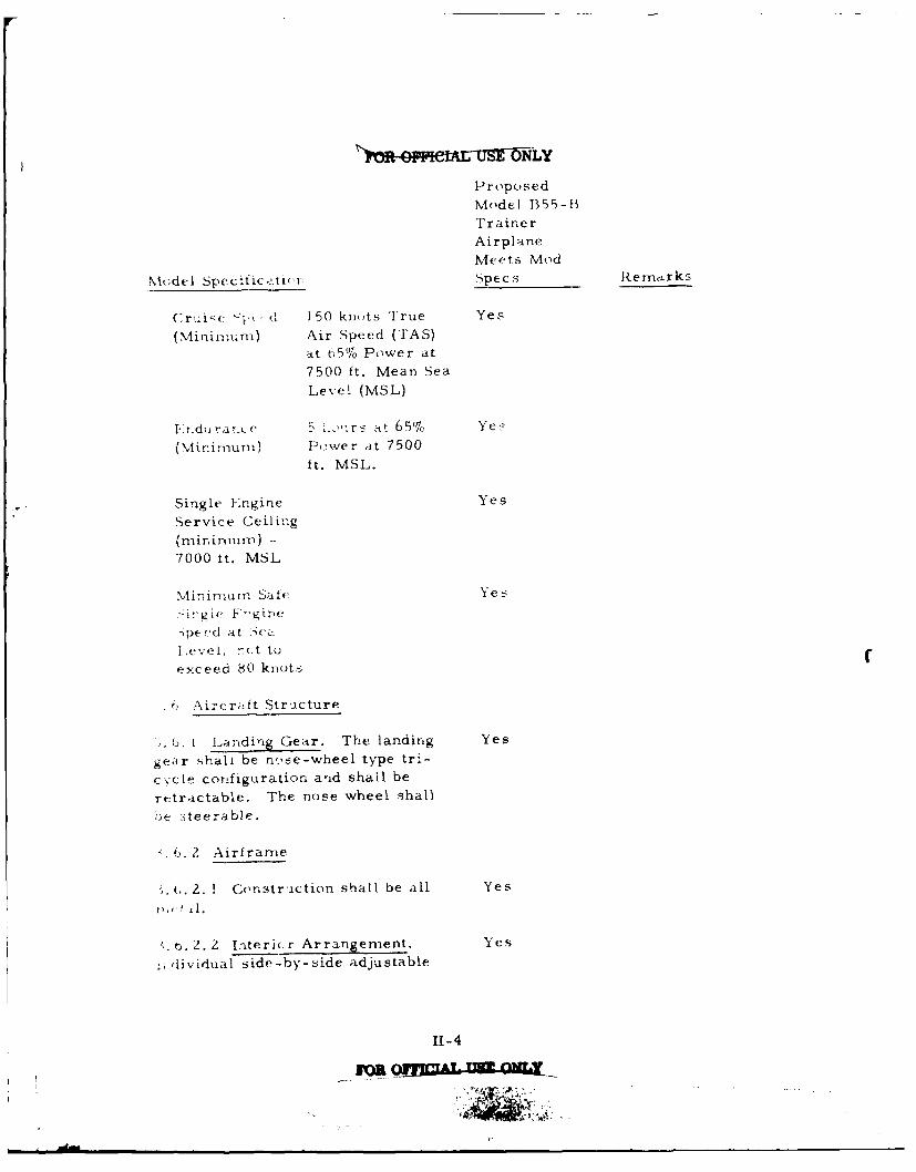
Cr1.i-; :pt, (1 150 kinots True Ye s
(Minimum) Air Speed (TAS)at 65% Power at
7500 ft. Mean Sea
Level (MSL)
Fnua nc 5 r at 65% Ye9
(Miinium) P, we r at 7500ft. MSL.
Single Engine Yes
Service Ceilin-g
(rnirdmirnux) -
7000 it. MSL
minimumn Saife Yes
- peed at ~LLevel, nct to
e-xceed 80 knots
6Aircr;-ft Str,.icture
0. 1 Landing Gear. The landing Yes
gear ihl be ncose-wheel type tri-
cy-cle conifiguration a-id shall be
t~ractable. The nose wheel shall6e :teerable.
. .2 Airframe
~6. 2. 1 Constr~iction shall be all Yes
r?,l 11l.
t). .Z -Interic r Arrangement. Yes
lividual side-by-side adjustable
11-4

Propo-,ed
Model B55-BI r-tinerAirplane
Meets Mod
M, dcl Spec,1cd' k p Specs Remarks
Ir,, t seats :,, tEe studert on the
left -tnd the i:" tr- ctor on the right.
Tv- additional scdt- immediately to
t-e rear t(, acci tninedate two addi-
,i( :.al tdents. Seating arrangement
nv: t permllit ex(lhange , f the tl-reetU;der't-, it'. 1iit.
Sh0,older h,, r- c -e s shall be re- Yes Test air-
',vircd ft t front seats ori. plane hadno shoulderharnesses.
-,. .. 2. 1 Of e (,) fire extin- Yes
g-i:sher and onme (1) first aid kit
- Ki 1 be installed and shall be
,.? s sible in fVight. (See
. pendix Ii. )
6. 2. " Flight and EngineC, nt r l .
2. . 2. . Dual fLight controls to Yes
tnclude adjustable rudder pedals'ith toe-type brakes.
1. 6. 2. 3.2 In-flight trim controls
for elevator, aileron, and rudder
are reqiired and shall be easily
4cces-ible to both the student
,,:d instructor.
. !. . 5. s Engine contrcl s shill!,I easiiy cco-,.sible t. both the
i de-t rd i.istractor.
U-5

Proposed
Model B55-B
I'rainerAirplane
Meets ModModel Specification Specs Remarks
5. b. 2. 3. 4 [.sitive control surface Yeslocks will be provided for ramp use.
1.6.2.4 Instr':mentation
3.6. 2.4. 1 The instrument panel Yes
shall have dual in.trurnentation in-corporating the "T' panel arrange-
rnent depicted ir. appendix I. Fur-ther, the two (2) attitude indicatorsshall have separate power sources.
3.6.2.4.2 Engine instruments Yes
shall be readable by both studentand instructor pilot.
i. 7 Lighting
I. 7. 1 Cockpit and instrument Yeslighting are required for night and
instrument flight rule operations.(Fluorescent and/or red floodlighting not acceptable as primary
lighting of instrument panel. )
3. 7.2 The aircraft shall have Yesrotating beacon(s) per FAA
requirements.
i. 8 Electronic Equipment
.8. 1 Electronics shall be in Yes
acc(rdance with appendix II.
3. 8. - Controls shall be easily Yes
accessible and readable to thestudent and instructor.
U-6

Proposed
Model B55-BTrainerAirplaneMeets Mod
Model Specification Specs Remarks
3.8. 3 Electrivics c.ntrols shall Yesbe front pare' mounted whereverpossible. Overhead control panels
are not acceptable.
3.9 Aircraft Systems
1.0. l Cabi: Heating. The air.- Yes
craft shall h-a\e a heating system
c,-pable :f maintaining a minimumof +40 0 F. cabin temperature with
-25"F. outside air temperature.
i.Q.2 Deicir.g Eq,ipment. Light- Yes Test air-
w-eight deicing and anti-icing equip- plane had notle:it shall be installed on the air- deicing or
crift as certific:ited. Deicing anti-icing
quipment must be capable of con- equipment.
tinac,. s operation for flight endur-
aonce of the aircraft.
1. 9. 3 Oxygen1 Equipment. Equip- Yes Test air-mrent for four I4) persons for a plane had no
mirimum of 1.5 hours duration at oxygen equip-
1 5. 000 feet MSL.. A liquid oxygen ment.
ivstem is not acceptable.
3.10 Stowage
3. 10. 1 Baggage space shall be Yes
provided for a minimum of 100 lb.,)f personal baggage.
3. 16. 2 Storage space within the Yes
cabin shall be provided for maps,charts, computers, and one (1)TM I1 -2557 (Jeppesen Case).
11-7
.. . r -- . . . . . .

Prt pu-ed
Model B55-BTrainerAirplane
Meets McdModel Specitication Specs Remarks
i. I M tn ..
. II. I Thc ,ircraft shall be Ye3furni-;hed with a Flight Operator'6
Mar.ual in accordance with FAAregllatiors and a Mairtera,-ce ard
Parts Manual.
11-8
' ' , ::0:'V .
~T ,. ,a

APPENDIX III - COORDINATfON
The followirg agecxies participated in the review of the te-t report:
US Arm\, Aviati',n School
3S Arih\ C-,nbat Developments Coemmand Aviation Agency
I$

APPENDIX IV- DISTRIBUTiON LISr
REPORT OF USATECOM PROJECT NO. 4-5-1001-01
No.
Agency Copies
Commanding General 10US Army Aviat',n Materiel Command
ATTN: SMOSM-EP
St. Louis, Missoar 6166
Cemmanding General 2US Army Materiei Co'nmand
ATTN: AMCMR-MCWaeh'ngton, D.C. 20115
Commanding General 2
US Continental Army Command
ATTN: Colo-el Greer
;:ort Monroe, Virginia
C..Ynmanding General 2
US Army Test and Evaluation Command
ATTN: AMSTE-BG.\herdeen Provlrig Ground, Maryland 21005
C,.nmranding General 2
rIS Army Mobility Command
A -C TN: AMSMO.. MWarren, Michigan
i13 -

AD Accession No.US Army Aviation Test Board. Ft. Rucker, Alabama. Final Report of
USATECOM Project No. 4-5-1001-01, Military Potential Test of theModel B55-B Fixed-Wing Instrument Trainer, 30 November 1964. DAProject No. None. 42 pp. . 8 illus. FOR OFFICIAL USE ONLY report.The Military Potential Test of the Model B55-B Fixed-Wing InstrumentTrainer was conducted by the US Army Aviation Test l3oard during theperiod 2 September to 26 October 1964 at Fort Rucker, Alabama.Flight under actual and simulated instrument conditions and demonstra-tions to personnel representing the US Army Aviation Center and theUS Army Aviation School were conducted during the test period. It wasfound that the Model B55-B test airplane as changed by the technicalproposal will meet all of the requirements contained in the Model Speci-fication. It was recommended that a confirmatory test be performedon the initial production airplane if the Model B55-B airplane is selectedas a fixed-wing instrument trainer.
AD Accession No.US Army Aviation Test Board, Ft. Rucker, Alabama. Final Report ofUSATECOM Project No. 4-5-1001-01, Military Potential Test of theModel B55-B Fixed-Wing Instrument Trainer, 30 November 1964, DAProject No. None. 42 pp., 8 illus. FOR OFFICIAL USE ONLY report.The Military Potential Test of the Model B55-B Fixed-Wag InstrumentTrainer was conducted by the US Army Aviation Test Board during theperiod 2 September to Z6 October 1964 at Fort Rucker, Alabama.Flight under actual and simulated instrument conditions and demonstra-tions to personnel representing the US Army Aviation Center and theUS Army Aviation School were conducted during the test period. It wasfound that the Model B55-B test airplane as changed by the technicalproposal will meet all of the requirements contained In the %4odel Speci-fication. It was recommended that a confirmatory test be performedon the initial production airplane if the Model B55-B airplane is selectedas a fixed-wing instrument trainer.
.: -