Embed Size (px)
Citation preview
Journal of Advanced Research in Applied Sciences and Engineering Technology
ISSN (online): 2462-1943 | Vol. 2, No. 1. Pages 57-66, 2016
57
Penerbit
Akademia Baru
Cable Theft Monitoring System (CTMS) Using
GSM Modem
S. A. Mohd Chachuli*, a, S. Mohd Nazri b, N. Yusop c and N. R. Mohamad d
Faculty of Electronic and Computer Engineering, Universiti Teknikal Malaysia Melaka,
Hang Tuah Jaya, 76100 Durian Tunggal, Melaka, Malaysia [email protected], [email protected], [email protected], [email protected]
Abstract – This system is developed to help in reducing the number of cable theft activities.
Currently, various methods have been applied by many companies to overcome this problem however
cable theft activities were still occurred. Thus, a new system based on simple method is proposed in
this paper to overcome these problems. The main objective of this project is to design and develop a
cable theft monitoring system (CTMS) using GSM Modem. The main parts for this system are
Peripheral Interface Controller (PIC) 16F877A microcontroller, voltage divider and temperature
sensor. From the experimental results, it showed that CTMS able to detect the voltage drop and
temperature changed with 99% of efficiency. This system is expected to enhance the capability of
existing system in term of compatibility. With significant improved in range and reliable data
accuracy in real time, this project promise a bright future to develop in reducing cable theft activities.
Copyright © 2016 Penerbit Akademia Baru - All rights reserved.
Keywords: GSM, cable theft, temperature sensor, voltage divider.
1.0 INTRODUCTION
Nowadays, cable thefts activities have been increased year by year in Malaysia. Total losses
incurred by Telekom Malaysia (TM) company were so great and about millions of dollars
were expensed in each year. In 2012, RM42 million have been expensed in covering cable
cost due to the cable theft in Malaysia [1]. Various methods have been applied by Telekom
Malaysia to overcome this problem such as cable theft prevention campaigns at the national
level among the community [2], organizing security patrols [1], wiping grease on telecom
poles [1], I-Watch (An Anti-Theft Cable Detection and Escalation System) installation [3],
and replacement of existing cable to fiber cables [4]. As part of the campaign, TM has begun
communicating the community service messages through print media, electronic media (TV
and radio), outdoor and online media [2]. For the security purposes, TM is collaborating with
PDRM, the local authorities, the other telecommunication company and utilities providers as
these are the key stakeholders in mitigating the cable theft issue [2]. TM has obtained
cooperation from all parties especially from local community and members of the public in
ensuring the communication facilities provided are preserved and protected from any
undesired incident such as cable theft, vandalism and any incident which results in
interruption of telecommunication services [2].
In order to reduce the number of cable theft cases in Malaysia, the latest technology was
developed by Telekom Malaysia (TM) which based on an alarm system. This system is
Journal of Advanced Research in Applied Sciences and Engineering Technology
ISSN (online): 2462-1943 | Vol. 2, No. 1. Pages 57-66, 2016
58
Penerbit
Akademia Baru
known as Anti- Theft Cable Detection and Escalation System (I-Watch). I-Watch is a system
that alerts telecom's operatives when the thieves attempt to cut a cable, and it also will inform
the security guard/operator the location of the incident is happened [1]. However, this system
need high cost to be developed and only selected recipients will received the notification
messages.
In other countries, Yuanyuan et al. introduced anti-theft monitoring method based on tracking
resonance frequency and it also able to detect the location of cable theft. Adjustable
capacitance, CN and adjustable inductance, LN are connected in parallel and then connected
in series with the simplified circuit of street lamp. By injecting a signal with variable
frequency into the monitoring circuit, phase difference between the signal voltage (U) and the
signal current (Iin) can be measured. When the phase difference is zero (that is resonance),
this signal frequency will be used as resonance frequency of the system [6]. Xiangjun et al.
proposed capacitance current resonance measurement principle. The capacitance of the cable
and the load can be calculated through the resonance measurement method, thus the length of
the cable can be calculated. The location of the breaking line can be detected, however this
system unable to identify whether the cable is stolen or not [7]. Zen and Yu analyzed the
principles and advantages of the current cable guard alarm technology. The mechanism use
fuzzy logic to judge the quality of the current, and calculate the protected setting value. It
gives out the reliable alarm signal through the electric current dynamic analyses when the
cable is cut off and stolen [8].
The aim of this project is to design and develop a system that able to help user in monitoring
the cable theft activity with a user friendly security system. Thus, a simple system based on
voltage divider method and connected with GSM system will be developed in this paper.
Next section will discuss on the topology and architecture of cable theft monitoring system
(CTMS), experimental results and analysis of experimental data.
2.0 METHODOLOGY
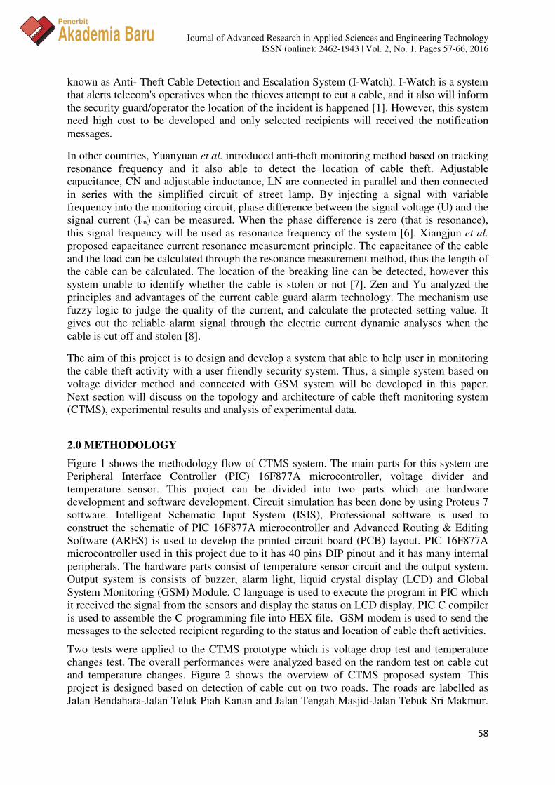
Figure 1 shows the methodology flow of CTMS system. The main parts for this system are
Peripheral Interface Controller (PIC) 16F877A microcontroller, voltage divider and
temperature sensor. This project can be divided into two parts which are hardware
development and software development. Circuit simulation has been done by using Proteus 7
software. Intelligent Schematic Input System (ISIS), Professional software is used to
construct the schematic of PIC 16F877A microcontroller and Advanced Routing & Editing
Software (ARES) is used to develop the printed circuit board (PCB) layout. PIC 16F877A
microcontroller used in this project due to it has 40 pins DIP pinout and it has many internal
peripherals. The hardware parts consist of temperature sensor circuit and the output system.
Output system is consists of buzzer, alarm light, liquid crystal display (LCD) and Global
System Monitoring (GSM) Module. C language is used to execute the program in PIC which
it received the signal from the sensors and display the status on LCD display. PIC C compiler
is used to assemble the C programming file into HEX file. GSM modem is used to send the
messages to the selected recipient regarding to the status and location of cable theft activities.
Two tests were applied to the CTMS prototype which is voltage drop test and temperature
changes test. The overall performances were analyzed based on the random test on cable cut
and temperature changes. Figure 2 shows the overview of CTMS proposed system. This
project is designed based on detection of cable cut on two roads. The roads are labelled as
Jalan Bendahara-Jalan Teluk Piah Kanan and Jalan Tengah Masjid-Jalan Tebuk Sri Makmur.
Journal of Advanced Research in Applied Sciences and Engineering Technology
ISSN (online): 2462-1943 | Vol. 2, No. 1. Pages 57-66, 2016
59
Penerbit
Akademia Baru
These roads will be connected directly to the microcontroller. If the voltage drop is detected
below 85% from the cable voltage, the microcontroller will send the signal to the LCD
display, buzzer, warning light and GSM. The temperature sensor also will send the signal to
the microcontroller if the temperature is detected more than 40ºC. Expected results of voltage
drop and temperature changes from CTMS system are described in Table 1 and Table 2.
Figure 1: Project flow chart
Figure 2: Overview of the project
Journal of Advanced Research in Applied Sciences and Engineering Technology
ISSN (online): 2462-1943 | Vol. 2, No. 1. Pages 57-66, 2016
60
Penerbit
Akademia Baru
Table 1: Expected results for voltage drop
Road
Voltage Drop
( Less than 10.5 V)
Normal Condition
(10.6 - 12V)
Jalan Bendahara-
Jalan Teluk Piah
Kanan
Buzzer
ON
Light
ON
GSM
active
Buzzer
OFF
Light
OFF
GSM
deactivate
Jalan Tgh
Masjid- Jalan
Tebuk Sri
Makmur
Buzzer
ON
Light
ON
GSM
active
Buzzer
OFF
Light
OFF
GSM
deactivate
Table 2: Expected results for temperature changes
Road
Temperature Change
( More than 40ᴼC )
Normal Condition
( 21ᴼC - 40ᴼC )
Jalan Bendahara-
Jalan Teluk Piah
Kanan
Buzzer
ON
Light
ON
GSM
active
Buzzer
OFF
Light
OFF
GSM
deactivate
Jalan Tgh Masjid-
Jalan Tebuk Sri
Makmur
Buzzer
ON
Light
ON
GSM
active
Buzzer
OFF
Light
OFF
GSM
deactivate
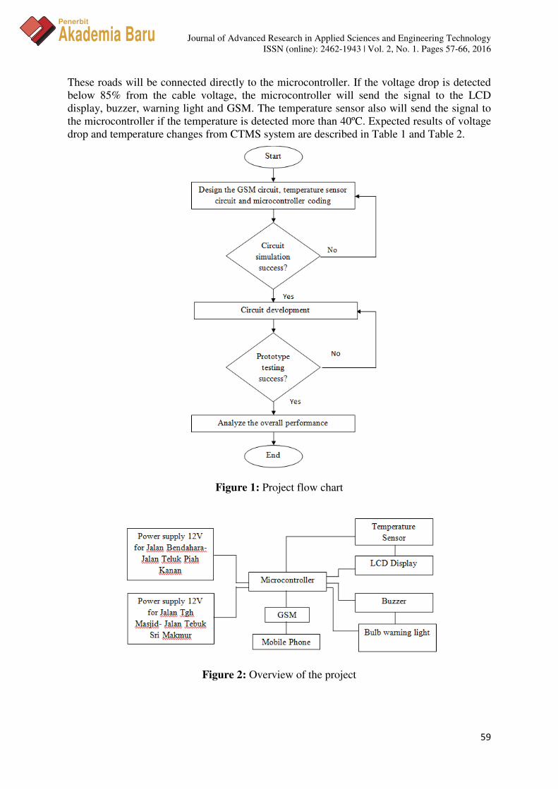
Figure 3: Circuit Construction in ISIS with PIC 16F877A Microcontroller
Condition
Condition

Journal of Advanced Research in Applied Sciences and Engineering Technology
ISSN (online): 2462-1943 | Vol. 2, No. 1. Pages 57-66, 2016
61
Penerbit
Akademia Baru
Circuit was constructed using Proteus Software is shown in Figure 3. Two different values of
supply voltages have been used in this system. First voltage is 12V; used for alarm system.
Second is 5V; used for PIC 16F877A Microcontroller, where the input voltage must be
around 4.5 to 5.5V. +5V can be determined by using LM7805 implementing +12V as input.
Figure 4 shows a prototype of CTMS system. After prototype is developed, three
experimental cases will be tested in this project which is voltage drop, temperature changes
and random test on voltage drop and temperature changes.
3.0 RESULTS AND DISCUSSION
Three cases have been analyzed in this project to ensure the expected result as shown in
Table 1 and Table 2 produced the same results in experimental cases. The analyses have been
carried out based on voltage drop, temperature changes and random test on voltage drop and
temperature changes.
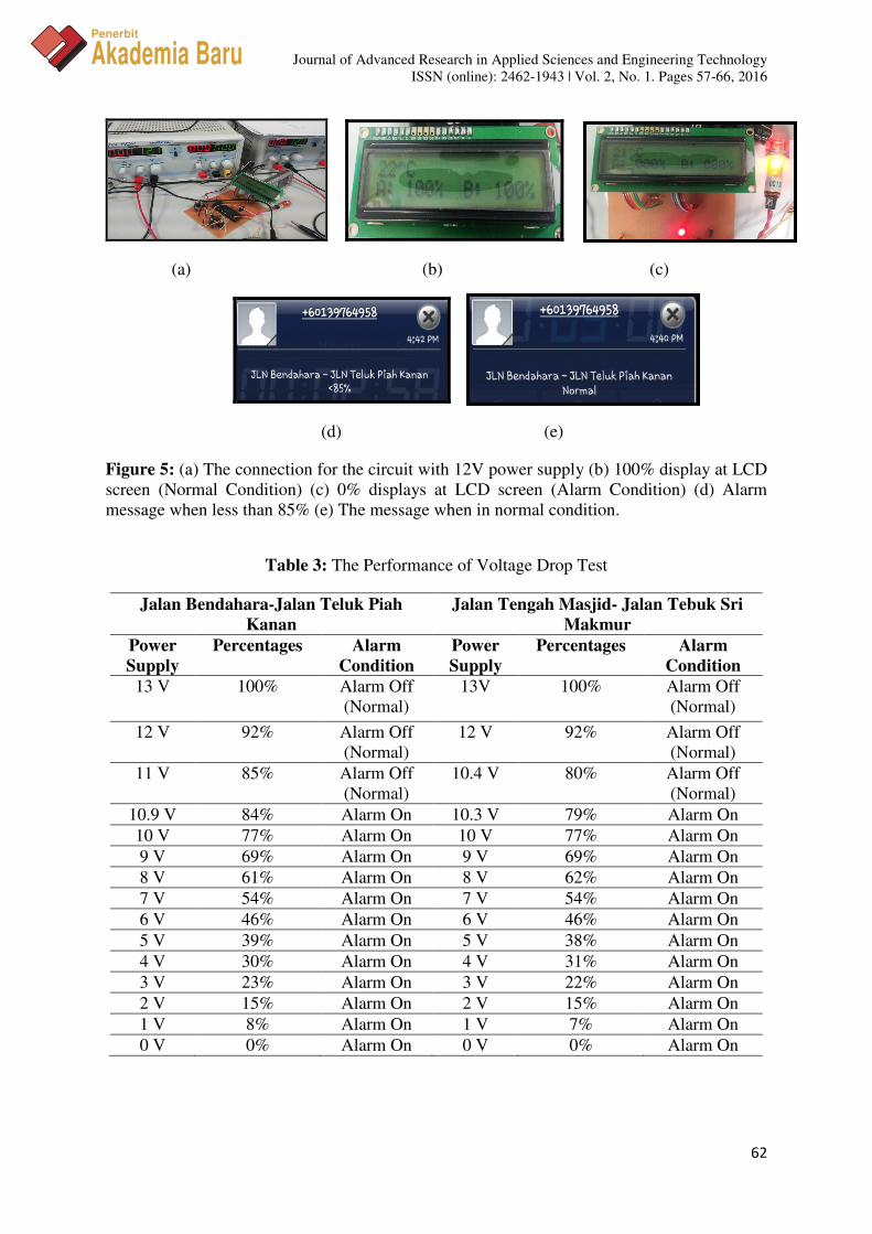
Case 1: Voltage Drop. Voltage drop is defined as the amount of voltage loss that occurs
through all or part of a circuit due to impedance. A voltage drop occurs across a component
that reduces the electrical potential of the electrons as they pass through it [9]. Voltage drop
is tested in this project due to the voltage of the cable will be affected during the cable
cutting. Figure 5(a) shows the construction of voltage drop test. The cable is supply with 12V
power supply to the controller circuit system. At first, the LCD display at the circuit will
show the percentage of the current voltage which is 100% as shown in Figure 5(b). When one
or both of cable along the road is cut, the voltage in the cable will drop and the LCD display
will show the percentage of current voltage drop immediately as shown in Figure 5(c).
Supply voltage that less than 85% from main supply voltage will activate the PIC 16F877A
microcontroller. The microcontroller will send the signal to the buzzer, warning light and the
GSM module will send the alarm message to the user. 85% voltage drop is chosen in this
system due to this voltage value can give early notification to the user when the cable is cut
or voltage drop is occurred at the location. If the voltage is increase again to 85% and above
(normal), the microcontroller will deactivate the buzzer and warning light, and then GSM
module will send the notification of normal condition message to the user. Figure 5(d) and
5(e) show the notification message received by the user when the cable is cut and after the
cable is in normal condition.
Figure 4: A prototype of CTMS system
Journal of Advanced Research in Applied Sciences and Engineering Technology
ISSN (online): 2462-1943 | Vol. 2, No. 1. Pages 57-66, 2016
62
Penerbit
Akademia Baru
(a) (b) (c)
(d) (e)
Figure 5: (a) The connection for the circuit with 12V power supply (b) 100% display at LCD
screen (Normal Condition) (c) 0% displays at LCD screen (Alarm Condition) (d) Alarm
message when less than 85% (e) The message when in normal condition.
Table 3: The Performance of Voltage Drop Test
Jalan Bendahara-Jalan Teluk Piah
Kanan
Jalan Tengah Masjid- Jalan Tebuk Sri
Makmur
Power
Supply
Percentages Alarm
Condition
Power
Supply
Percentages Alarm
Condition
13 V 100% Alarm Off
(Normal)
13V 100% Alarm Off
(Normal)
12 V 92% Alarm Off
(Normal)
12 V 92% Alarm Off
(Normal)
11 V 85% Alarm Off
(Normal)
10.4 V 80% Alarm Off
(Normal)
10.9 V 84% Alarm On 10.3 V 79% Alarm On
10 V 77% Alarm On 10 V 77% Alarm On
9 V 69% Alarm On 9 V 69% Alarm On
8 V 61% Alarm On 8 V 62% Alarm On
7 V 54% Alarm On 7 V 54% Alarm On
6 V 46% Alarm On 6 V 46% Alarm On
5 V 39% Alarm On 5 V 38% Alarm On
4 V 30% Alarm On 4 V 31% Alarm On
3 V 23% Alarm On 3 V 22% Alarm On
2 V 15% Alarm On 2 V 15% Alarm On
1 V 8% Alarm On 1 V 7% Alarm On
0 V 0% Alarm On 0 V 0% Alarm On
Journal of Advanced Research in Applied Sciences and Engineering Technology
ISSN (online): 2462-1943 | Vol. 2, No. 1. Pages 57-66, 2016
63
Penerbit
Akademia Baru
Table 3 shows the performance of voltage drop test. At first, the supply voltage is set to 13V
and next, it will be decreased by 1V. From the experimental results, it showed that this
system able to work effectively for both roads and the produced results are similar to the
expected results shown in Table 1.
Case 2: Temperature Changes. Temperature changes are the changes of temperature value
either increased or decreased from the normal value of temperature. In this project, the
temperature sensor will sense the temperature in range between 21ᴼC until 40ᴼC in the
circuit. Normally, the electronic circuit is difficult to overheat because usually the circuit is
installed in an air-conditioned room and this circuit also is constructed with heat sink.
However, overheat also able to occur if the air space around the circuit is covered with dust
or the circuit is not in services for a long time.
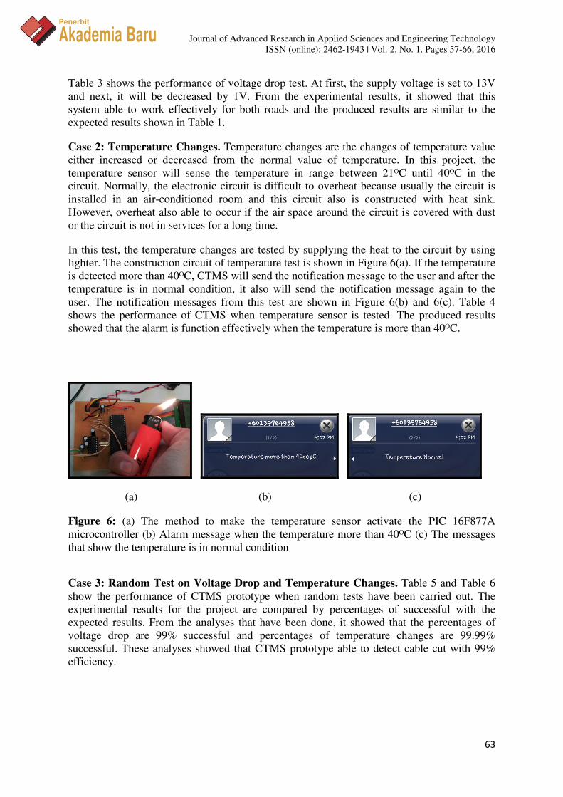
In this test, the temperature changes are tested by supplying the heat to the circuit by using
lighter. The construction circuit of temperature test is shown in Figure 6(a). If the temperature
is detected more than 40ᴼC, CTMS will send the notification message to the user and after the
temperature is in normal condition, it also will send the notification message again to the
user. The notification messages from this test are shown in Figure 6(b) and 6(c). Table 4
shows the performance of CTMS when temperature sensor is tested. The produced results
showed that the alarm is function effectively when the temperature is more than 40ᴼC.
(a) (b) (c)
Figure 6: (a) The method to make the temperature sensor activate the PIC 16F877A
microcontroller (b) Alarm message when the temperature more than 40ᴼC (c) The messages
that show the temperature is in normal condition
Case 3: Random Test on Voltage Drop and Temperature Changes. Table 5 and Table 6
show the performance of CTMS prototype when random tests have been carried out. The
experimental results for the project are compared by percentages of successful with the
expected results. From the analyses that have been done, it showed that the percentages of
voltage drop are 99% successful and percentages of temperature changes are 99.99%
successful. These analyses showed that CTMS prototype able to detect cable cut with 99%
efficiency.
Journal of Advanced Research in Applied Sciences and Engineering Technology
ISSN (online): 2462-1943 | Vol. 2, No. 1. Pages 57-66, 2016
64
Penerbit
Akademia Baru
Table 4: The performance of temperature changes test
Changes Of Temperature
Value ( ᴼC)
Alarm Condition
21ᴼC Off (Normal)
22ᴼC Off (Normal)
23ᴼC Off (Normal)
24ᴼC Off (Normal)
25ᴼC Off (Normal)
26ᴼC Off (Normal)
27ᴼC Off (Normal)
28ᴼC Off (Normal)
29ᴼC Off (Normal)
30ᴼC Off (Normal)
31ᴼC Off (Normal)
32ᴼC Off (Normal)
33ᴼC Off (Normal)
34ᴼC Off (Normal)
35ᴼC Off (Normal)
36ᴼC Off (Normal)
37ᴼC Off (Normal)
38ᴼC Off (Normal)
39ᴼC Off (Normal)
40ᴼC Off (Normal)
41ᴼC On
42ᴼC On
43ᴼC On
Table 5: Performance of voltage drop on random test
Power
Supply
Experimental
Results
Expected
Results
Alarm
Condition Percentages
11.3 V 86 % 86% Alarm Off
(Normal)
100%
10.3 V 79 % 78 % Alarm On 99%
8 V 61 % 62 % Alarm On 99%
5 V 39 % 38 % Alarm On 99%
2 V 15 % 15 % Alarm On 100%
Journal of Advanced Research in Applied Sciences and Engineering Technology
ISSN (online): 2462-1943 | Vol. 2, No. 1. Pages 57-66, 2016
65
Penerbit
Akademia Baru
Table 6: Performance of temperature changes on random test
Changes of Temperature
Value ( ᴼC)
Experimental
Results
Expected
Results
Percentages
27 ᴼC Alarm Off
(Normal)
Alarm Off
(Normal)
100%
35 ᴼC Alarm Off
(Normal)
Alarm Off
(Normal)
100%
41 ᴼC Alarm On Alarm On 100%
43 ᴼC Alarm On Alarm On 100%
4.0 CONCLUSION
The main objective of this project is successfully achieved where cable theft monitoring
system using GSM modem have been successfully designed and developed. This project able
to detect the voltage drop on the cable, changes of temperature in the circuit and sends the
notification message to the user. The microcontroller also able to activate the buzzer and give
warning light, thus it indicates that the cable theft is occurred. The location of cable theft
based on two roads can be identified by checking the notification message. Analyses of
overall performance of CTMS showed that this system able to work with 99% efficiency.
Thus, it can be concluded that this CTMS system is working successfully when cable is cut
and under high temperature. This system also offers portability and flexibility to the user.
ACKNOWLEDGMENT
The author would like to thank Universiti Teknikal Malaysia Melaka, Malaysia (UTeM) for
funding and provide facilities to this project.
REFERENCES
[1] S.I. Lee, (2012). Improved security sees a reduction in cable theft cases. Retrieved on
23th July 2013.
[2] Kugan (2012). TM cable theft prevention campaign. Retrieved on 15th August 2013.
[3] Bernama (2012). TM gunasistem I-Watch kesansertamertakecuriankabel. Retrieved on
15th August 2013.
[4] J. Erma Yusnida, (2013). TM bendungkecuriankabel. Retrieved on 19th August 2013.
[5] Telekom Malaysia Kuala Selangor (2013). Report from Kuala Selangor monthly cable
theft.
[6] Yuanyuan, Wang, Jian Jinbao, Zeng Xiangjun, and Liu Sidong. "Anti-theft monitoring
and location system for cable of street lamp." In Electric Utility Deregulation and
Restructuring and Power Technologies (DRPT), 2011 4th International Conference on,
pp. 913-915. IEEE, 2011.

Journal of Advanced Research in Applied Sciences and Engineering Technology
ISSN (online): 2462-1943 | Vol. 2, No. 1. Pages 57-66, 2016
66
Penerbit
Akademia Baru
[7] Xiangjun, Zeng, Jin Guangming, Jin Wangyi, and Xu Yao. "Anti theft and monitoring
system of street lamp power cables." In Power and Energy Engineering Conference,
2009. APPEEC 2009. Asia-Pacific, pp. 1-4. IEEE, 2009.
[8] Yu, Zhen. "Study on a new cable guard alarm system based on fuzzy state estimation."
In Computer Science & Education, 2009. ICCSE'09. 4th International Conference on,
pp. 1867-1872. IEEE, 2009.
[9] Rashid, Muhammad Harunur. Power electronics: circuits, devices, and applications.
Pearson Education India, 2003.


![Nakisa, Bahareh,Rastgoo, Mohammad Naim, Ahmad Nazri, Mohd … · 2020. 4. 6. · Nakisa, Nazri, Rastgoo and Abdullah[14] presented a survey of PSO-based algorithms that solved Premature](https://img.pdfslide.us/doc/110x75/60691b9189775b15653eeaab/nakisa-baharehrastgoo-mohammad-naim-ahmad-nazri-mohd-2020-4-6-nakisa.jpg)