Embed Size (px)
Citation preview

1
S-72.3260 Radio Resource Management Methods 3 cr
LecturerProf. Riku JänttiE-mail: [email protected]
Tel. +358 9 451 2353E219
AssistantLic. Tech. Mohammed Al Rawi
E-mail: [email protected]. +358 9 451 4905
316 (OK7)
http://tll.tkk.fi/en/Studies/S-72.3260/
S-72.3260 Radio Resource Management Methods 3 op TKK Communications Laboratory 2
Tentative schedule
Week Day Lectures Exercises12 Tue 1 Introduction
Wed 2 Handovers, dynamic channel allocationThu
13 TueWedThu 3 Power control
14 Tue 4 Admission and load controlWed 5 Schedulign principlesThu 1 Handovers, dynamic channel allocation
15 Tue 6 Slow schedulingWed 2 Power controlThu 3 Admission and load control
16 Tue 7 Channel adaptive schedulingWed 4 Slow schedulingThu 8 Multicarrier systems: sub-channel allocation, bit loading
17 Tue 9 Mesh networks: topology control Wed 5 Opportunistic schedulingThu 6 Multi carrier & mesh systems
18 Tue 7 Old exam

2
S-72.3260 Radio Resource Management Methods 3 op TKK Communications Laboratory 3
Course material• Requirements
– J. Zander and S.-L. Kim, Radio Resource Management for Wireless Networks, Artech House, 2001. Chapters 1 – 7
– Lecture notes• Slides (available in internet)• Notes (paper copy)
– Tutorial notes • Recommended reading
– Selected articles
S-72.3260 Radio Resource Management Methods 3 op TKK Communications Laboratory 4
Radio Resource Management• Radio spectrum is a scarce resource that should be
utilized as efficiently as possible. Consequently, the spectrum must be shard among many users.
• In practice, all sharing (multiple access) techniques causes interference among the users.
• The objective of Radio Resource Management is to control the division of resources (power, time slots, frequency channels, spreading codes etc.) among the users such that – The quality of service demands of the users are
satisfied– The spectral efficiency is maximized– Interference is mitigated– Operator revenue is maximized
3
S-72.3260 Radio Resource Management Methods 3 op TKK Communications Laboratory 5
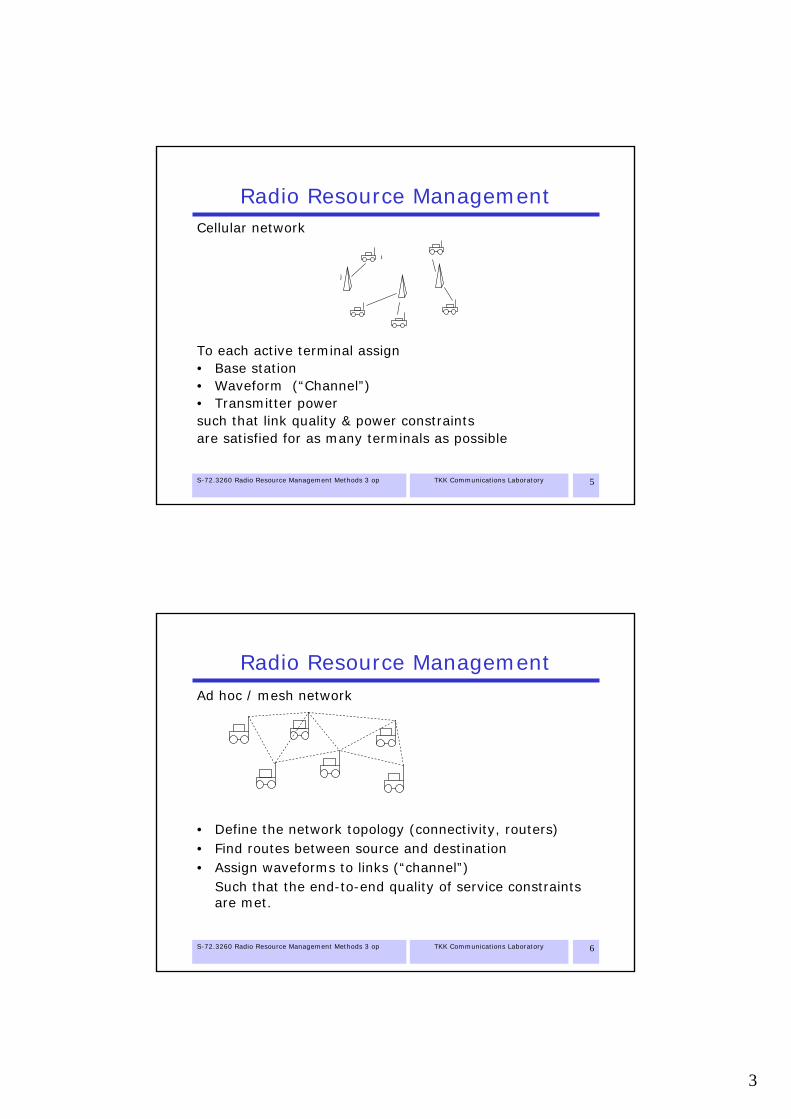
Radio Resource ManagementCellular network
To each active terminal assign• Base station• Waveform (“Channel”)• Transmitter powersuch that link quality & power constraints are satisfied for as many terminals as possible
i
j
S-72.3260 Radio Resource Management Methods 3 op TKK Communications Laboratory 6
Radio Resource ManagementAd hoc / mesh network
• Define the network topology (connectivity, routers)• Find routes between source and destination• Assign waveforms to links (“channel”)
Such that the end-to-end quality of service constraints are met.

4
Wireless access technologies
S-72.3260 Radio Resource Management Methods 3 op TKK Communications Laboratory 8
Wireless access technologies• Frequency division multiple access (FDMA)• Time division multiple access (TDMA)• Frequency hopping (FH)• Direct sequence spread spectrum (DSSS)• Code division multiple access (CDMA)• Orthogonal frequency division multiplexing (OFDM)• Spatial Division Multiple Access (SDMA)

5
S-72.3260 Radio Resource Management Methods 3 op TKK Communications Laboratory 9
F/TDMA• FDMA: Each user has a dedicated frequency channel• TDMA: Each user has a dedicated time slot• In practice, combination of these two are needed
– A single frequency band is divided among the users in time.– Uplink and donwlink is separated either in frequency (FDD:
Frequency division duplex) or in time (TDD: Time division duplex)– Adjacent cells (coverage areas of base station antennas) are
separated in frequency in order to decrease co-channel interference.
– Cells utilizing the same frequency are placed in distance D fromeach other which depends the number of frequency channels available for the network operator.
– The greater the reuse-distance D is, the less the cells interfere with each other, but the less bandwidth is available per cell.
S-72.3260 Radio Resource Management Methods 3 op TKK Communications Laboratory 10
F/TDMA
• Each cell is using a dedicated frequency channel and each user in a cell has a dedicated time slot.
• Utilized e.g. in GSM• Example
– Consider downlink of cell S– Other cells using the same frequency
cause co-channel interference:
DS
( )( ) 2
0
3
31 366 3
m m
S m
k
D R kR k
R k Nγ
−
−
=
=
= ≈+
R
Minimum signal-to-noise-ratioif all the interfering base stationstransmit with fixed power
Frequency reuse factor (cluster size)

6
S-72.3260 Radio Resource Management Methods 3 op TKK Communications Laboratory 11
2
Timing• Different users have different propagation times• In multi-path fading channels, also the delay spread
must be taken into account
1 23 km
12 km
≈ 10 μs≈40 μs
1 2
≈ 60 μs
1 22Time slots
Guard timeSlot 1 Slot 2
S-72.3260 Radio Resource Management Methods 3 op TKK Communications Laboratory 12
Frequency Hopping• Slow Frequency Hopping
– The utilized frequency changes from slot-to-slot based on predefined hopping sequence
– Averages the interference in frequency domain
1Cell1
3 4t
f
1Cell2
2 3 4t
f
12 3
4t
f
12
34
t
f
2
TDMA SFH-TDMA

7
S-72.3260 Radio Resource Management Methods 3 op TKK Communications Laboratory 13
F/TDMA RRM challenges• Admission and handover control
– Admission control based on available channels– Reservation of guard channels for handoff calls– …
• Dynamic channel allocation– Fixed channel allocation is based on conservative
estimates on the interference and traffic load leading to trunking losses (the number of channels per cell is low)
– By controlling the reuse of channels based on instantaneous traffic load and interference capacity can be enhanced.
• Slow power control– Fixed transmit power can cause unnecessary large
interference leading to long reuse distance.– By controlling the power dynamically to meet the SINR
requirements, interference can be mitigated and reuse distance decreased
S-72.3260 Radio Resource Management Methods 3 op TKK Communications Laboratory 14
DSSS• Direct sequence spread spectrum• Spreading
– Single symbol is represented by a pulse of length Tb
– Before transmission the pulse is multiplied with a spreading sequence consisted of W shorter pulses chips of length Tc.
Data symbols{-1,1}
Spreading code
noise
kT
k kT
b
b( +
z1)
+1
-1
Equivalent lowpass model in BPSK caseCorrelaror receiverChannel

8
S-72.3260 Radio Resource Management Methods 3 op TKK Communications Laboratory 15
DSSS
Power spectrum of the signalafter spreading
Power spectrum of the signalbefore spreading
Jamming signal
Despreading concentrates the symbolEnergy into narrow band and dividesthe jamming signal energy to wide band
S-72.3260 Radio Resource Management Methods 3 op TKK Communications Laboratory 16
DSSS
-10 -8 -6 -4 -2 0 2 4 6 8 1010-6
10-5
10-4
10-3
10-2
10-1
100
fTb
Pow
er S
pect
ra
Before spreadingAfter spreading
9
S-72.3260 Radio Resource Management Methods 3 op TKK Communications Laboratory 17
DSSS
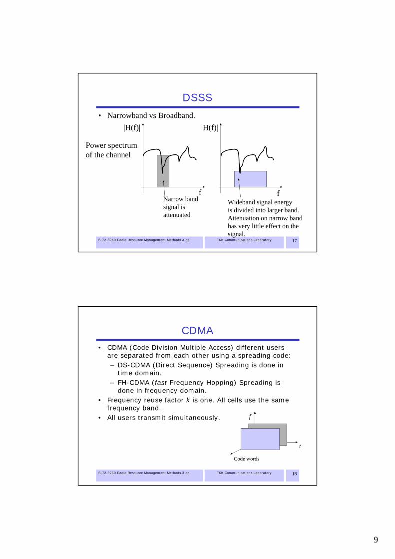
• Narrowband vs Broadband.|H(f)|
f
|H(f)|
f
Power spectrumof the channel
Narrow bandsignal is attenuated
Wideband signal energyis divided into larger band.Attenuation on narrow bandhas very little effect on thesignal.
S-72.3260 Radio Resource Management Methods 3 op TKK Communications Laboratory 18
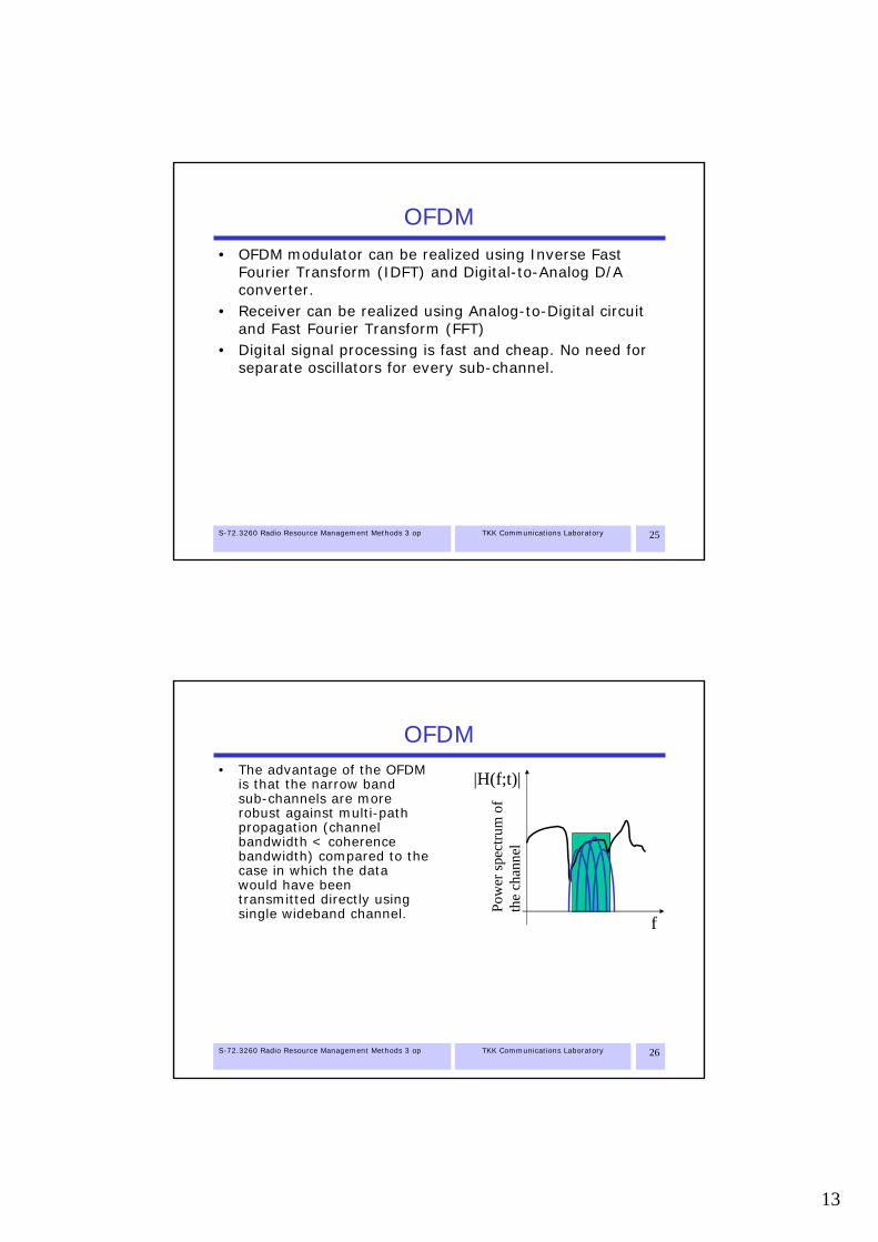
CDMA• CDMA (Code Division Multiple Access) different users
are separated from each other using a spreading code:– DS-CDMA (Direct Sequence) Spreading is done in
time domain.– FH-CDMA (fast Frequency Hopping) Spreading is
done in frequency domain.• Frequency reuse factor k is one. All cells use the same
frequency band.• All users transmit simultaneously.
t
f
KoodiCode words

10
S-72.3260 Radio Resource Management Methods 3 op TKK Communications Laboratory 19
DS-CDMA• Multi-user interference appears as noise. • Bit error probability on a Gaussian channel depends on
the signal-to-noise+interference ratio (SINR)
• Capacity is interference limited. – With fixed bit energy Eb, the bit error rate grows as
the number of interfering users increase,– Alternatively for fixed bit error probability, the
required bit energy grows as the number of users incerease.
– Pole capacity: Number of users for which Eb →∞
{ } ( )0 0
Pr error 1 12 2
b b
b b
E WEQ Q Q SINRM E N ME NW
⎛ ⎞ ⎛ ⎞⎜ ⎟ ⎜ ⎟
= = =⎜ ⎟ ⎜ ⎟⎜ ⎟ ⎜ ⎟+ +⎜ ⎟⎜ ⎟
⎝ ⎠⎝ ⎠
S-72.3260 Radio Resource Management Methods 3 op TKK Communications Laboratory 20
CDMA RRM challenges• Fast power control
– Fast fading causes the received signal to fluctuate.• Smaller SINR-margin is needed if the fading is
compensated by using fast power control.– Near-far problem: Unless power is controlled in a cell,
power received from users close to the base station can be several orders of magnitude larger than the power from users on the edge of the cell. Transmit power control is needed to balance the power levels at the receiver
• Admission and load control based on interference power– Admission and load control should keep the transmit
power control loop stable• Rate control
– In 3G CDMA systems, the data rate of the users can be controlled dynamically based on the traffic demand and available resources (in terms of interference level)

11
S-72.3260 Radio Resource Management Methods 3 op TKK Communications Laboratory 21
OFDM• Orthogonal Frequency Division Multiplexing
– Symbol of length T is modulated using e.g. BPSK.– T is relatively large => Narrow band signal.– Ns (even) symbols are transmitted in parallel such
that the carrier frequencies are 1/T apart from each other.
12
22
1( ) exp 2
s
ss
N
NkN
k
t ks t I i tT TT
π−
+=−
⎛ ⎞⎛ ⎞ ⎛ ⎞⎜ ⎟= Π⎜ ⎟ ⎜ ⎟⎜ ⎟⎝ ⎠ ⎝ ⎠⎜ ⎟
⎝ ⎠∑
2 12
sN tiTe
π ⎛ ⎞−⎜ ⎟⎝ ⎠
22
sNi t
eπ ⎛ ⎞−⎜ ⎟
⎝ ⎠
∑{ }nI
PSKmodulator
Serial to parallel
2 22
sN tiTe
π ⎛ ⎞−⎜ ⎟
⎝ ⎠
Inverse Fouriertransform of Nsconsecutive symbols
1I
2I
sNI
S-72.3260 Radio Resource Management Methods 3 op TKK Communications Laboratory 22
OFDMSpectrum of OFDM modulated signal
-15 -10 -5 0 5 10 150
0.1
0.2
0.3
0.4
0.5
0.6
0.7
0.8
0.9
1
Carrier
8sN =

12
S-72.3260 Radio Resource Management Methods 3 op TKK Communications Laboratory 23
OFDM44 Hz
s
c
Nf
==
0 0.1 0.2 0.3 0.4 0.5 0.6 0.7 0.8 0.9 1-3
-2
-1
0
1
2
3
4
OFDM modulated signal
Subcarriers
S-72.3260 Radio Resource Management Methods 3 op TKK Communications Laboratory 24
OFDM• Adjacent channels are orthogonal to each other (do not
interfere with each other)
• Receiver
( )( )( )0
1 1 1exp 2 exp 2 exp 2 ,
1 exp 2 1 02 ( )
Tt k t l k li t i t i t dt k lT T T T T TT T
i k li k l
π π π
ππ
⎛ ⎞ −⎛ ⎞ ⎛ ⎞ ⎛ ⎞ ⎛ ⎞ ⎛ ⎞Π Π = ≠⎜ ⎟⎜ ⎟ ⎜ ⎟ ⎜ ⎟ ⎜ ⎟ ⎜ ⎟⎝ ⎠ ⎝ ⎠ ⎝ ⎠ ⎝ ⎠ ⎝ ⎠⎝ ⎠
= − − =−
∫
2 12
sN tiTe
π ⎛ ⎞− −⎜ ⎟⎝ ⎠
22
sNi t
eπ ⎛ ⎞− −⎜ ⎟
⎝ ⎠
2 22
sN tiTe
π ⎛ ⎞− −⎜ ⎟
⎝ ⎠
∫
∫
∫
T
1I
2I
sNI
13
S-72.3260 Radio Resource Management Methods 3 op TKK Communications Laboratory 25
OFDM• OFDM modulator can be realized using Inverse Fast
Fourier Transform (IDFT) and Digital-to-Analog D/A converter.
• Receiver can be realized using Analog-to-Digital circuit and Fast Fourier Transform (FFT)
• Digital signal processing is fast and cheap. No need for separate oscillators for every sub-channel.
S-72.3260 Radio Resource Management Methods 3 op TKK Communications Laboratory 26
OFDM• The advantage of the OFDM
is that the narrow band sub-channels are more robust against multi-path propagation (channel bandwidth < coherence bandwidth) compared to the case in which the data would have been transmitted directly using single wideband channel.
|H(f;t)|
f
Pow
ersp
ectru
mof
the
chan
nel

14
S-72.3260 Radio Resource Management Methods 3 op TKK Communications Laboratory 27
OFDM• Intersymbol interference ICI caused by multipath propagation
can be removed partly by using a cyclic prefix. • Channel equalization is much simpler than in wideband case.
(Smaller number of taps is needed)
End of symbolDelayed replicaof the transmittedsignal.
Cyclic prefix Integration time of FFT(Receiver only considers this part of the signal)
Phase change caused by change of bit
(Nonlinear distortion)
Delayed replica appears as a phase shift
S-72.3260 Radio Resource Management Methods 3 op TKK Communications Laboratory 28
OFDMA• Orthogonal Frequency Division Multiple Access
– Different users are multiplexed together
IFFT
User 1
User 2 D/A
User N
Seria
l to
para
llel

15
S-72.3260 Radio Resource Management Methods 3 op TKK Communications Laboratory 29
OFCDMA• Orthogonal Frequency and Code Division Multiplexing
OFCDM/ Multi-carrier CDMA (MC-CDMA)– Combination of OFDM and CDMA– High spectral efficiency– Robustness against multi-path propagation – Multiple access flexibility, good robustness against
inter-cell interference.
S-72.3260 Radio Resource Management Methods 3 op TKK Communications Laboratory 30
OFDMA RRM Challenges• Sub-band and transmit power allocation
– Sub-bands can be allocated to the users based on their channel responses. Allocate channel to the user who benefits the most from it.
– Transmit power could be allocated to maximize the system capacity by allocating power inversely proportional to the channel gain (waterfilling)
• Time-frequency domain scheduling– Packet scheduling allocates time-frequency chunks to
the users • Curse of dimensionality
– It is not possible to have individual channel state feedback from all sub-carriers. Hence, the carriers need to be grouped and joint feedback for a group is generated.

16
S-72.3260 Radio Resource Management Methods 3 op TKK Communications Laboratory 31
SDMA• Multi-antenna (MIMO, Multiple Input –
Multiple Output) system, in which multiple users share the same frequency band.
• Data streams are separated using spatial processing.
SDMA capacity region (MMSE-SIC receiver)
2 22
1 10
2
0
1log 1
1log 1 , 1,2
i i ii i
i i i
r pN
r p iN
= =
⎛ ⎞≤ +⎜ ⎟
⎝ ⎠⎛ ⎞
≤ + =⎜ ⎟⎝ ⎠
∑ ∑ h
h1r
2r
S-72.3260 Radio Resource Management Methods 3 op TKK Communications Laboratory 32
SMDMA RRM Challenges• Curse of dimensionality
– Channel state for each user and each sub-carrier is nr x nt matrix where nr is the number of receive antennas and nt is the number of transmit antennas
– In TDD mode, the transmitter can have channel state information due to channel reciprocity. However, the interference seen by the receivers cannot be known.
– Optimization of feedback information is a challenging problem. That is finding the tradeoff between capacity gain and signalingcost in terms of number of required feedback bits.
• Power allocation problem– How should the transmit power be divided among the various data
streams (among antennas and sub-carriers) such that quality of service constraints are met and capacity is maximized.
• Schedulign problem– How to allocate the users on the various sub-carriers such that
their transmissions can be orthogonalized. Now up to nt data streams could be served simultaneously on a given sub-carrier.

17
S-72.3260 Radio Resource Management Methods 3 op TKK Communications Laboratory 33
Relay and mesh networks• In traditional wireless
networks the terminals are connected to access point through one hop.
• In mesh networks, there can be multiple hops between source and destination.
• The relay nodes can be either fixed or mobile.
R32 relay
relayrelay
relay
relayrelay
BS/AP
S-72.3260 Radio Resource Management Methods 3 op TKK Communications Laboratory 34
RRM for Relay and mesh networks• Topology control
– Changing the transmit power controls the connectivity of the nodes as well as data rates of the links
• Routing and load balancing– There can be multiple paths between source and
destination. Selection of which path to use affects the network load distribution
• Link scheduling / frequency assignment– In single frequency network, a node cannot transmit
and receive simultaneously. Also links nearby can interfere with each other so their transmission must be coordinated.

18
S-72.3260 Radio Resource Management Methods 3 op TKK Communications Laboratory 35
Integrated reconfigurable networks• Paradigm of the traditional cellular
– Anytime anywhere (with fixed [low] quality)– Always connected– Single operator, single access technology networks
with global roaming• Paradigm for the future cellular
– Anytime anywhere (with varying service quality)– Always Best Connected (ABC)– Multi-access networks, seamless internetworking
with IP based core networks– Integration and reconfiguration– Cognitive interference aware radios
S-72.3260 Radio Resource Management Methods 3 op TKK Communications Laboratory 36
Integrated reconfigurable networks• Multi-access
– Fixed network (ISP)– GSM/GPRS– WCDMA– WiFi WLAN– WiMax WMAN– Etc.
• Multi-hop– Mesh networks– Ad hoc access
• Multi-operator– Licensed bands– Unlicensed bands– Spectrum pooling– Dynamic spectrum assignment
PAN 1
IP core
CorporateIntranetISP
PAN1
RAN1
RANn
PAN2 PAN
3
RAN1
RANn
Radio accessOperator 2

19
S-72.3260 Radio Resource Management Methods 3 op TKK Communications Laboratory 37
RRM challenges for reconfigurable wireless
• Dynamic spectrum allocation– Co-existence strategies– Resource allocation between competing networks– Spectrum sharing & trading
• End-to-end QoS management– Dynamic network selection– User terminal driven RRM decisions
Interference

20
S-72.3260 Radio Resource Management Methods 3 op TKK Communications Laboratory 39
Interference• Intersymbol interference (ISI)
– In frequency selective fast fading channel, the received signal contain the transmitted symbol and delayed replicas of previously transmitted symbols. This form of interference can be mitigated e.g. by using Viterbi equalizer.
• Co-channel interference– In F/TDMA system interference occurs due to reuse
of the same channel in other cells.
111
1 1 1
111
D
√3DTDi Di+1
i i+1
S-72.3260 Radio Resource Management Methods 3 op TKK Communications Laboratory 40
Interference• Adjacent frequency channels are not completely orthogonal
due to nonlinear distortions caused e.g. by the power amplifier. Also the Doppler effect causes frequency shift that needs to be taken into account.
• A guard band is needed to keep the adjacent channel interference at tolerable level.
• In WCDMA: Adjacent Channel Leakage Ratio (ACLR): Uplink: 33 dB and 43 dB, Downlink: 45 dB and 50 dB
3.84 Mhz
5 Mhz
n200 kHz
Guard band
P
Nf 1Nf + 2Nf +
1ACKR 2ACKRfN center frequency of channel N

21
S-72.3260 Radio Resource Management Methods 3 op TKK Communications Laboratory 41
Interference• In CDMA systems the interference can be divide into
two parts– Intracell interference
• Interference due to simultaneous transmissions taking place in the same cell
– Intercell interference• Interference due to simultaneous transmissions in
neighboring cells– The ratio between intercell and intracell interference
depends on overlap between the cells and the utilized handover strategy (hard/soft). Typically the intracell interference is dominating.
S-72.3260 Radio Resource Management Methods 3 op TKK Communications Laboratory 42
Interference• Downlink interference
– Interference is generated by the co-channel base stations.
– The interference power level generated by a cell depends on its aggregate traffic. => Interference power is slowly changing and can be predicted.

22
S-72.3260 Radio Resource Management Methods 3 op TKK Communications Laboratory 43
Interference• Uplink interference
– In F/TDMA and OFDMA systems the uplink interference is generated by single mobile in each co-channel cell. The interference is highly random, since it depends on the mobile positions and scheduling decisions of the individual cells.
– In CDMA case, the interference is generated by the aggregate of the users making it less random. However, the smaller the traffic the more unpredictable is the interference.
S-72.3260 Radio Resource Management Methods 3 op TKK Communications Laboratory 44
Interference• In TDD systems it could happen that different cells have
different frame lengths for uplink and downlink transmissions or they are out of sync. Hence, there can be interference between uplink and downlink transmissions of different cells. This can cause very high interference, since transmitter in one cell can be in the close proximity of a receiver of another cell. Downlink transmission is more sensitive to uplink interference than downlink is to uplink.
• In ad hoc networks, the interference is generated by simultaneously active radio links. Here too the transmitter of one link can be in close proximity of another. This situation isusually handled by scheduling the transmission of the interfering links e.g. by using CSMA/CA random access protocol.

23
S-72.3260 Radio Resource Management Methods 3 op TKK Communications Laboratory 45
Signal-to-interference+noise ratio (SINR)
• Signal-to-interference+noise ratio is a quality metric for the quality of the received signal.
• It is defined as the ratio between received signal power S and received interference power I + receiver noise power σ2
SINR = S/(I+σ2)
• Another closely related quality metric is the received bit energy Eb to interference + noise spectral density I0 + N0
• Bit energy S=r Eb where r is the bit rate • Spectral density of the noise and interference can be obtained
by dividing them by the bandwidth W
Eb/(I0+N0) = W/r·SINR
• In SINR equation, we have σ2=N0W and I = I0W
S-72.3260 Radio Resource Management Methods 3 op TKK Communications Laboratory 46
Quality of Service• Channel quality in terms of bit error rate (BER), block
error rate (BLER) and frame error rate (FER) are monotonically decreasing or at least non-increasing functions of SINR.
• The channel capacity (in terms of bit rate) is typically non-decreasing function of SINR.
Anders Furuskär, Radio Resource Sharing and Bearer Service Allocation for Multi-Bearer Service, Multi-Access Wireless Networks, PhD Thesis, TRITA-S3-RST-0302, Radio Communication Systems, Dept of S3, KTH, April 2003.
R code rate

24
S-72.3260 Radio Resource Management Methods 3 op TKK Communications Laboratory 47
Interference modeling • Consider a discrete time equivalent low pass model for a
narrowband signal• The signal is sampled with sampling time higher than the
symbol duration– A denotes the set of active transmitters– bi denotes the complex symbol transmitted by user i
E{bi}=0, E{|bi|}=1– wi =[wi1
* wi2* … wiW
*]* is the sampled waveform. – W is the number of samples per symbol– Cross correlation between waveforms wi*wj
=ρij
– pi denotes the transmit power of the signal– hij denotes the channel response in a channel between user j and
receiver i– zi =[zi1
* zi2* … ziW
*]* denotes the white thermal noise vector at receiver i zik~N(0,σ2)
E{zi}=0, E{zizi*}=Iσ2/W
S-72.3260 Radio Resource Management Methods 3 op TKK Communications Laboratory 48
Interference modeling• Transmitted signal
• Received signal at receiver i
• The interference signal at the receiver is given by
i i i ip b=s w
noisesignal
interference
i ij j j j i ii i i i ij j j j ij A j A
j i
h p b h p b h p b∈ ∈
≠
= + = + +∑ ∑r w z w w z
i ij j j jj Aj i
h p b∈≠
= ∑x w { } { }
{ } 2*
i ij j j jj Aj i
i i ij jj Aj i
E h p E b
E h p
∈≠
∈≠
= =
=
∑
∑
x w 0
x x

25
S-72.3260 Radio Resource Management Methods 3 op TKK Communications Laboratory 49
Interference modeling• Matched filter output
* *
* * *
noisesignal
interference
i ii i i
i ii ii i i ii ij j ij j ii ij Aj i
r h
r h h p b h h p b h zρ∈≠
=
= + +∑
w r
S-72.3260 Radio Resource Management Methods 3 op TKK Communications Laboratory 50
SINR• Signal-to-interference+noise (power) ratio SINR:
– Squared cross-correlation θij=E{ρij2 }
– Link gain gij=|hij|2
• General form of SINR
{ }{ } { }
2* 4 2
2 2 22 22 2 2 2* *
ii ii i iii i ii i
i
ii ij ij j ii ij ij jii ij ij j j ii i j ì j ì
j ì
E h h p b h p h p
h h E p h h E pE h h p b h z ρ σ ρ σρ≠ ≠
≠
Γ = = =⎧ ⎫⎪ ⎪ + ++⎨ ⎬⎪ ⎪⎩ ⎭
∑ ∑∑
2
ii ii
ij ij jj Aj i
g p
g pθ σ∈≠
Γ =+∑

26
S-72.3260 Radio Resource Management Methods 3 op TKK Communications Laboratory 51
SINR• Given SINR requirement γi, we can rewrite the SINR
equation as follows
• Define – a normalized link gain matrix H=[hij]
hij=gijθij/gii, i≠ j and hii=0 – normalized noise vector η=[ηi], ηi=γiσ2/gii
• The SINR equation can be written in matrix form as follows:
p=Hp+η
2ij ij
i i jj ì ii ii
gp p
g gθ σγ
≠
⎛ ⎞= +⎜ ⎟
⎝ ⎠∑
S-72.3260 Radio Resource Management Methods 3 op TKK Communications Laboratory 52
Controlling the interference• Transmit power control:
– Find p such that
• Rate control (link adaptation). – Find ri such that Eb/(I0+N0) can be supported
2
ii ii i
ij ij jj Aj i
g p
g pγ
θ σ∈≠
Γ = ≥ ⇔ ≥ ++∑
p Hp η
0 0
tgt
bi
i
EWr I N
γ⎛ ⎞
= ⎜ ⎟+⎝ ⎠i iγΓ ≥

27
S-72.3260 Radio Resource Management Methods 3 op TKK Communications Laboratory 53
Controlling the interference• Admission and load control
– Control the set of active users A such that the power such that
• Packet scheduling– Control A(t) and ri(t) as a function of time such
and E{ri(t)}>Rreq
i iγΓ ≥
( ) ( )i it i A tγΓ ≥ ∈
S-72.3260 Radio Resource Management Methods 3 op TKK Communications Laboratory 54
Time scales of RRM• Slow mobility, fast RRM
• Fast mobility, fast RRM Time scale of interest
Time scale of interest
Channel stays essentially constant during the observationtime. RRM algorithms have time to converge beforethe channel state changes.
Channel stays essentially constant during theone control interval (e.g. TTI). Channel is (slowly) changing, but the channel processcan be assumed to be stationary
Mean

28
S-72.3260 Radio Resource Management Methods 3 op TKK Communications Laboratory 55
Time scales of RRM• Fast mobility, slow RRM
Channel obtains variations are very fast compared to the control interval. Channel is averaged out
– RRM is slow compared to the fading but not the path loss change due to mobility: Channel is stationary
– RRM is slow compared to fading and mobility: Channel is non-stationary
– RRM is very slow: Mobile position gets averaged out
S-72.3260 Radio Resource Management Methods 3 op TKK Communications Laboratory 56
Conclusions• All practical multiple access schemes cause multi-user
interference (MUD) to appear• Signal-to-noise+interference ratio is one of the key
parameters to model the impact of the MUD on the system performance.
• Consequently, many RRM schemes try to control the SINR by controlling the rate (required SINR), transmit power, number of simultaneously active users etc.


![Publication [IV] - TKK](https://img.pdfslide.us/doc/110x75/61f2fb971a17171fc95f7b67/publication-iv-tkk.jpg)