Embed Size (px)
Citation preview

T·
REVISIONS
SYMBOL DESCRIPTION DATE APPROVAL
- KEz.eASEl) ~/14/"'_ ~~.2-
SHEET REVISION STATUS
SH 1 2 3 4 5 6 7 8 9 10 11 12 13 14 15 16 17 18 19 20
REV -- -- -- -- -- -- -- -- -- -- -- -- -- -- -- -- -- -- -- --SH 21 22 23 24 25 26 27 28 29 30 31 32 33 34 35 36 37 38 39 40
REV -- -- -- -- -- -- -- --ORIGINATOR '/1 ~. PJ 3l:h~
FSC: 5935 T.J. Perry/Paramax
APPROVED ~~\ ~WS\J~ S.E. Archer-DavlesyParamax ~ Iblq~ Connectors, Electrical,
Rectangular, Polarized CODE 311 APPRO~ :!It. '3!~/f"2-
Shell, EMI Shielding S.A. Naus/GSF~~ 1/ (Size 1) For Space Flight
311 SUPERVISO~ -4/f2--Use, Detail specification
CODE For G.P. Kramer, Jr./GSFC
ADDITIONAL APPROVAL - S-311-P-718/3
-~
NATIONAL AERONAUTICS AND SPACE ADMINISTRATION GODDARD SPACE FLIGHT CENTER GREENBELT, MARYLAND 20771
CAGE CODE: 25306 PAGE 1 OF 28
,.,.' -~ , "-:n
1 SCOPE
1.1 specification for connectors. This specification covers the detail provisions for rectangular, polarized shell, electrical connectors capable of continuous operation in a space environment within a temperature range of -65° to +125°C. Connectors use rear-insertion and rear-release crimp-type contacts, supplied separately. Detail specification GSFC S-311-P-718/2 covers the contacts for the electrical connectors. The connectors covered by this detail specification (GSFC S-311-P-718/3) shall be compatible (intermateable and intermountable, but not totally interchangeable) with connectors delineated by GSFC S-311-P-718/1. The connectors are designed to be used with EMI backshells furnished under GSFC S-311-P-718/4.
1.2 GSFC General specification. Unless otherwise noted, all connector provisions and requirements of GSFC general specification S-311-P-718 apply to this specification.
1.3 Connector-type designations. Connectors shall be of the following type designations, and shall be ordered by their type designations only.
700-42/3
contact Type (1.3.2)
contact Arrangement (1.3.1)
GSFC prefix (standard for all connector-type designations)
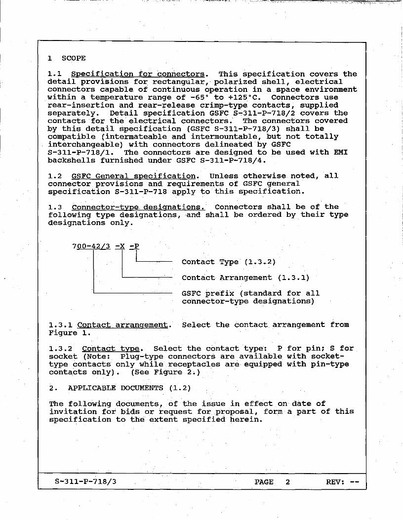
1.3.1 Contact arrangement. Select the contact arrangement from Figure 1.
1.3.2 Contact type. Select the contact type: P for pin; S for socket (Note: Plug-type connectors are available with sockettype contacts only while receptacles are equipped with pin-type contacts only). (See Figure 2.)
2. APPLICABLE DOCUMENTS (1.2)
The following documents, of the issue in effect on date of invitation for bids or request for proposal, form a part of this specification to the extent specified herein.
S-311-P-718/3 PAGE 2 REV: --
----~ ,_! - ----

2.1 Specifications.
2.1.1 Federal.
QQ-A-200/8
QQ-A-250/11
QQ-C-533
ZZ-R-765
2.1.2 Military.
MIL-C-26074
MIL-C-17
MIL-W-16878
MIL-C-22520
MIL-T-22910
MIL-I-43553
MIL-G-45204
2.1.3 NASA/GSFC.
GSFC S-311-P-718
GSFC S-311-P-718/1
GSFC S-311-P-718/2
S-311-P-718/3
Aluminum Alloy Bar, Rod, Shapes and Tube, Extruded, 6061 and 6062
Aluminum Alloy 6061, Plate and Sheet
Copper-Beryllium Alloy strip (Copper Alloy Numbers 170 and 172)
Rubber, Silicone, Low and HighTemperature and Tear Resistant
Coatings, Electroless Nickel, Requirements for
Cables, Radio Frequency; coaxial, Dual Coaxial, Twin Conductor, and Twin Lead
wire, Electrical, Insulated, High Temperature
crimping Tools, Contact, Electric, Hand, General Specification for
Tool, Crimping, Hand, for Crimp style Electric Terminal and Shield Ferrule
Ink, Marking, Epoxy Base
Gold Plating, Electrodeposited
Connectors, Electrical, Rectangular (Power and Coaxial Contacts) (Including EMI Shielding) for Space Flight Use, General Specification for
Connectors, Electrical, Rectangular, Polarized Shell, For Space Flight Use, Detail specification for
contacts, Power and coaxial, Removable, for Electrical Connectors (Sizes 1, 2, and 3), Detail Specification for
PAGE 3 REV: --

GSFC S-311-P-718/4
2.2 Standards.
MIL-STD-1285
MS3197
DOD-STD-100
2.3 Other pUblications.
NAS1668
Backshell Kits, Connector, Rectangular, EMI Shielding, strain Relief (Sizes 1, 2, 3), For Space Flight Use, Detail Specification for
Marking of Electrical and Electronic Parts
Gage Pin, for Socket Engagement Test
Engineering Drawing Practices
Plug, Grommet Sealing, Electrical Connector
2.4 Order of precedence. The order of precedence delineated in the general specification shall apply.
3. REQUIREMENTS (1.2)
3.1 Materials. design. and construction. Connectors shall be of the materials, design, construction, and physical dimensions as specified herein (Figures 1 and 2). They shall be constructed to accommodate removable crimp-type power and coaxial contacts conforming to specification GSFC S-311-P-718/2. (Reference: Finishes not specified, which are known to sUblimate in a hard vacuum, such as cadmium, shall not be used.) Connectors shall be designed to be mated when the distance between the plug and receptacle flange is achieved as indicated in Figure 2A and Figure 2B.
3.1.1 Material weight loss (vacuum). Connector materials used shall be such that in no case will outgassing limits of 3.2.3 be exceeded when tested in accordance with GSFC S-311-P-718.
3.1.2 Insert material. Inserts shall be made of Epiall 1908 or Epiall 1914. The inserts shall meet the material weight loss requirement of 3.1.1.
3.1.3 Contact designation. Contact locations (numerals) shall appear on the front and rear faces of inserts to identify the contacts (Figure 1). The socket contact identification shall correspond to the mating-pin contact identification.
3.1.4 Shell design. The shell shall be designed to positively retain the insert and be so constructed that the insert cannot be removed without the use of tools. Shells shall be scoop-proof and shall be chamfered at the mating surfaces. The connector
S-311-P-718/3 PAGE 4 REV:

shall be so designed that a single shell configuration pair will accommodate either contact arrangement (Figure 1). Flange location shall be as indicated in Figure 2.
3.1.4.1 Shell polarization. Polarization shall be accomplished by a shaped-shell design. Polarization shall be accomplished before engagement of the contacts.
3.1.4.2 Shell material and finish. The shells shall be made of aluminum: alloy in accordance with QQ-A-200/8, 6061-T6511, or QQ-A-250/11, 6061-T651. The connector's shell surface shall be nickel plated per MIL-C-26074, Class 4, Grade B. A pair of blue painted alignment stripes shall be located as per Figure 2A and 2B. The paint shall be per MIL-I-43553, Type I. The paint shall meet the weight loss requirements of 3.1.1.
3.1.4.3 Shell spring fingers. Spring fingers shall be designed to make electrical contact with the mating shell without interfering with proper engagement. The fingers shall be positively retained about the shell periphery per Figure 2 and shall be made from beryllium copper alloy in accordance with QQ-C-533. Finger plating shall be gold plated per MIL-G-45204, Type II, Class II, Grade C, over Type I, Class 1, Grade A over copper flash per MILC-14550, .00001 - .00010 inches thick.
3.1.5 Connector mating/demating tooling. The supplier shall design and/or recommend the required tooling necessary for connector mating/demating.
3.1.6 Contact retention clips. Contact retention clips shall be heat treated to a hardness of 65,000 psi. The clip material shall be beryllium copper.
3.1.7 Interfacial seal. All pin contact inserts shall have a resilient interface seal bonded to the front face, with individual pin barriers. The pin barrier projections shall seal in their respective lead-in chamfers of the hard face socket insert. The resilient interfacial seal shall provide individual contact seals in the mated condition to ensure circuit isolation between each contact and contact to shell. The interfacial seal shall meet the material weight loss requirement of 3.1.1.
3.1.8 Wire sealing member (rear grommet). A wire sealing member shall be provided on the rear of both the plug and receptacle and it shall not be removable from the connector. It shall be designed to provide sealing to meet the environmental requirements of this specification when using wire of outer diameters within the range shown below. When wires of smaller diameter are specified, (e.g., for qualification) the use of shrink-fit tubing is permitted, as required. The grommet shall meet the material weight loss requirement of 3.1.1. The grommet shall be of a triple-gland design.
S-311-P-718/3 PAGE 5 REV: --

Finished Wire outside Dimensions (in. )
contact Cavity
8 16 RG-393jU RG-142BjU
Wire Size
8 (1) 16-18-20(1) RG-393jU(2) RG-142BjU(3)
(1)MIL-W-16878. type EE (2)MIL-C-17j127 (3)MIL-C-17j60
Min.
0.197 0.064 0.380 0.190
Max
0.217 0.095 0.400 0.200
3.1.9 Sealing plugs. The same sealing plugs shall be capable of being used in both connector plugs and receptacles. The sealing plug identification shall be as follows:
882-214-002* NAS1668-2 882-214-004* 882-214-003*
For size 8 grommet cavity For size 16 grommet cavity For RG-393jU grommet cavity For RG-142BjU grommet cavity
*G&H Technology, Inc. FSCM 99447
3.1.10 Angular connect and disconnect capability. The connector pairs, when suitably mounted with one connector half on a floating, spring supported plate, must be capable of engagement or separation without binding, degradation or jamming and without exceeding acceptable force limits when the two connector mounting surfaces are engaged or separated at angles of up to +10 0
combined with a +0.12 in. misalignment.
3.1.11 Connector weight The maximum weight of each connector half (including a full complement of contacts) minus the backshells shall be in accordance with Figure 1A through Figure 10.
3.1.12 Coaxial contact installation. Coaxial plug contacts (pin center contacts) shall only be installed in plug connector halves. Coaxial receptacle (jack) contacts (socket center contacts) shall only be installed in receptacle connector halves.
S-311-P-718j3 PAGE 6 REV: --
-- !

3.2 Performance. (1.2)
3.2.1 Dielectric withstanding voltage. The applicable dielectric withstanding voltage shall be in accordance with Table 1.
Table I. Dielectric withstanding voltage.
ac V (rms) 60 Hz
Sea Level 70,000 ft
Size 8 or 16 contact-tocontact and contact-to-shell
coaxial outer contact-toshell; coaxial outer contactto-nearest size 8 or 16 contact
coaxial outer contact-tocoaxial center contact
1000 350
1000 350
1000 350
3.2.2 contact retention (in insert). The applicable axial load shall be in accordance with Table II.
Table II. contact retention.
contact Type Force in Ib (min.)
Size 16 15 Coaxial (RG-'393/U) 20 Coaxial (RG-142B/U) 15
3.2.3 Vacuum effects (material outgassing) The material outgassing limits of the insert, interfacial seal and grommet individually shall not exceed 1.0 percent in total weight loss and 0.1 percent in volatile-condensable material.
3.2.4 Contact resistance. The contact resistance shall not exceed the limits of Table III.
S-311-P-718/3 PAGE 7 REV: --

Table III. Voltage dro12·
AWG Voltage Drop contact Wire Test Current Voltage Drop (mV max)
Size Size (Amperes) (mV max) After Durability
8 8 46 26 32 8 12 23 42 51
16 16 13 49 59 16 22 5 73 88
3.2.5 Insert retention (in Shell). The applicable load shall be 60 lb per square in. (psi).
3.2.6 Connector mating and demating forces. The connectors shall not exceed the forces listed in Table IV.
Table IV. Connector mating and demating forces.
Force in lb (max) contact
Arrangement Mating Demating
No. 1 141 141
No. 2 225 225
No. 3 280 280
No. 4 280 280
3.2.7 Contact engagement and se12aration. Contacts shall conform to the forces in Table V. Test pins shall be in accordance with MS3197, except as noted.
3.2.8 Moisture resistance. Connectors shall meet the dielectric withstanding voltage, when tested as specified in 4.1.2, and the applicable insulation resistance as follows:
a. After step 6(c), the insulation resistance shall be 1 megohm, min.
S-311-P-718/3 PAGE 8 REV: --

b. After 24 hours, (g) , the insulation resistance shall be 1,000 megohms.
Table V. contact engaging and separating forces.
Size 8 Size 16 Coax. (RG-393jU) (center contact) Coax. (RG-142BjU) (center contact) Coax. (RG-393jU) (outer contact) Coax. (RG-142BjU) (outer contact)
*Min. = +0.0001 -0.0000
Engag-ing
Max.
75.0 17.0
11.0
11.0
48.0
48.0
Force in Ounces
Sepa- Test Pin rating Diameter
Min. Min.*
5.0 MS3197-8X1 2.0
1.0 0.0630
1.0 0.0480
3.0 0.4333
3.0 0.3122
*Max = +0.0000 -0.0001
4. QUALITY ASSURANCE PROVISIONS (1.2)
or Socket in inches
Max. *
MS3197-8Y1
0.0660
0.0490
0.4356
0.3146
4.1 Quantity of samples for qualification. The quantity of connector samples for each connector type designation desired for qualification shall be two, minimum, together with their counterpart connectors and equipped with appropriate EMI shielding straight strain relief clamps per GSFC S-311-P-718j4. The connectors shall have their full complement of contacts. The connector type designation shall be specified.
4.1.1 Connector wiring. The power contacts shall be wired using wire per specification MIL-W-16878, Type E or Type EE) as follows: Note: The percentages listed are only approximate; however, all contact cavities shall be filled.
a. Size 8-1 AWG 8 - 25% Size 8-3 AWG 10 - 25% Size 8-2 AWG 12 - 25% Size 8-2 AWG 14 - 25%
b. Size 16-1 AWG 16 - 30% Size 16-1 AWG 20 - 30% Size 16-2 AWG 22 - 20% Size 16-2 AWG 26 - 20%
S-311-P-718j3 PAGE 9 REV: --

c. Coax (RG-393/U) - RG-393/U* - 100%
d. Coax (RG-142B/U) - RG-142B/U* - 100%
*MIL-C-17
4.1.2 Moisture resistance. Mated connectors shall be subjected to the moisture-resistance test as specified in the general specification (1.2), except as modified in 3.2.8.
a. After completion of the sixth step of the final cycle and after removal of surface moisture from the insulator, the insulation resistance shall be measured while observing the limit of 3.2.8(a).
b. The sea-level dielectric-withstanding~voltage test shall be sustained with 600 V ac (rms) 60 Hz applied.
c. After the 24-hour conditioning period, the inSUlation resistance shall again be measured,while observing the limit of 3.2.8(b).
4.2 Final inspection. Connectors final inspection shall consist of these examinations, inspections and tests.
a. Each connector shall be 100 percent inspected per the workmanship provisions of the general specification, GSFC S-311-P-718.
b. Each connector shall be checked for:
1. critical Dimensions (per applicable figure) 2. Weight (3.1.11) 3. Mating and Demating Test (3.2.6) 4. Contact Retention Tests (all contacts) (3.2.2) 5. Electricals
( a) DWV (3. 2 • 1) (b) IR (3.6.1-General Specification)
5. PREPARATION FOR DELIVERY (1.2)
6. NOTES (1.2)
custodian:
Code 311.2 Goddard Space Flight Center Greenbelt, MD 20771
S-311-P-718/3 PAGE 10 REV: --

THIS PAGE LEFT INTENTIONALLY BLANK
S-311-P-718/3 PAGE 11 REV: --

en I
w t-> t-> I
ttl I ~ t-> 0)
"-w
~ tr:I
t-> t\)
~ <: ..
1.525
1.450
Co.NT ACT TYPE QUANTITY Co.NNECTQR WEIGHT 1.325 Po.UNDS (MAX) (3.1.11) 1.275
SIZE 8 8 PLUG RECEPTACLE Fr 1.125 SIZE 16 60 Ir 1.100 Co.AX ~RG-393/U) 6 2.75 2.85 Co.AX RG-142B/U) 6 1--.925
1 Is 11 til 'i I 4 I . 1.175 080 T -LI_--;-
1. .750. "''''''
L4-4-4-+I+
.100
No.TES: UNLESS o.THERWISE SPECIFIED.
1. INTERPRET PER Do.D-STD-l00. 2. ALL DIMENSlo.NS ARE BASIC. 3. DIMENSlo.NS SHo.WN ARE TYPICAL ALL 4 QUADRANTS.
4. DATUM I-A-I PASSES THRU THE CENTER o.F Ho.LES INDICATED •.
5. DATUM I-B-I IS PERPENDICULAR TO. DATUM I-A-I AT THE
MIDPo.lNT BETWEEN Ho.LES INDICATED •.
6. No.TES ALSO. APPLY TO. -2 Co.NTACT ARRANGEMENT, FIGURE lB. 1.250 --'
FIGURE 1A - Co.NTACT ARRANGEMENT-l
(PAGE 1 o.F 2)
-A-
r 6X RG-142 B/U Co.NTACT
160X SIZE 16 Co.NTACT
6X RG-393/U Co.NTACT
8X SIZE 8 Co.NTACT
~-' ~"t
111 '.
<; :~,

S-311-P-718/3
FRONT FACE OF RECEPTACLE (PIN POWER CONTACTS)
FIGURE 1 A - CONTACT ARRANGEMENT-1 . (PAGE 2 OF 2)
PAGE 13 REV: --

en I
w I-' I-' I
"'C I
-..! I-' 00 "w
~ G) I;I:j
I-' til>
~ <: .. I I
CONTACT TYPE QUANTITY CONNECTOR WEIGHT POUNDS (MAX) (3.1.11)
SIZE 8 26 PLUG RECEPTACLE SIZE 16 86
COAX ~RG-393/U) a 2.75 2.85 COAX RG-142B!U) 2
-~~ ---- --- ---
.175
NOTE: REFER TO NOTES.· FIGURE lA. (CONTACT ARRANGEMENT-l)
,.. 1.496 .-,
FIGURE lB - CONTACT ARRANGEMENT-2
(PAGE 1 OF 2)
-A-
86X SIZE 16 CONTACT
r.:p--:--~ 26X SIZE 8 ':::II Jh. CONTACT
-8-
2X RG-142 8/U CONTACT
i'
f.
'I 'I i
i'll
S-311-P-718/3
FRONT FACE OF RECEPTACLE (PIN POWER CONTACTS)
FIGURE 1 B -.: CONTACT ARRANGEMENT-2 (PAGE 2 OF 2)
PAGE 15 REV: --

.,r-------
C/l I
w I-' I-' I
"'d I
...,J I-' ():)
........ w
~ I-' 0'\
[;J <l ..
TOP (REFERENCE)
.183
1 ••••••••••••••• 15 .16 •••••••••••••••• 31
. t I 4~.·.·.·.·.·.·.· .... ·.·.·.·.·.·.·+662 1.085 .930 , t 1 63 ••••••••••••••• 77
.775.620 'I. 78 •••••••••••••••• 93 .465 .310 .94 ................ 108
.091
.182
" . . ~~~ •••••• 115 ;$-••••• ~122+-1 ........ , -'-----'---'----,---,.----r-----..---.-123 •••••• #29~~~6 ••••••• 136
137 ••••••••••••••• 151 " 152 •••••••••••••••• 167
1 f J 168 •• -$-............. 182 -;-------f---'-
183 •••••••••••••••• 198 I .155
1.267 199 ••••••••••••••• 213 -+-_____ .,---1...
214 .................. 229+-----'-------'-2301.'.'.1.'-+-1.1.1 .......... 244 -r-----'-----------'-
.091
.274 CONTACT TYPE QUANTITY , CONNECTOR WEIGHT
SIZE 8 SIZE 16
COAX tG-.39.3/U) COAX RG-1428/U)
FRONT FACE OF RECEPTACLE (PIN POWER CONTACTS)
FIGURE 1 C - CONTACT ARRANGEMENT-.3
0 244
0 0
POUNDS (MAX) (3.1.11)
PLUG I RECEPTACLE
2.75 2.85
it "
ill }'
'1' '~
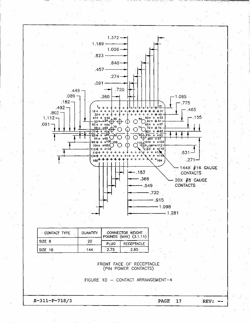
.449 .089
.182
.492 .802
1.189 ---.....,
.823 ----i-l
.457---...-j
.091-----"
.360
10 0 0 0 0 0 0 0 0 0 0 -+- 1:..:5~......1-·160 000 0 0 0 01++++++++31
1.085
.775
.465
1.112 320 0 0 0 0 J 0 0 0 0 0 0 -+- 46 -1----'-
470 0 04%9 55~ 59 500 0 0·.52 53 ~4 0 0 600 -+- 61 -1-____ ......1-
.091 620 0 064 650 0 067
680 069£00 ~. 074.075.0 -+-76-1----.-L ~:!::::!:::::!:~i~t7~7j+~0~07gq:r. 800 0 +62 -I-~-.-~~----L--.L. 1 63+ 0 0650-66
0 0 90cp91_-,-0_-0~""'O..;;9;::...3-4--4--!----+--4-__ _
940 095 . 960 0 97
1040 01050 0 0 Yl;-rr-o 112-+-------r' -.--4---+98+ 0 0100 106 fl 11~10 0 6103
-j---l--'---- 11 3+ 0 0115 1160 0 0116 1190 0 0 0 0 0 0 0 0 0 " 0 0 01
-.--1---.,........,..,..--'- 134+ 0 0 0 0 0 0 010 0 0 0
. 150+++++++
.631
.271
144X #16 GAUGE CONTACTS
CONTACT TYPE
SIZE 8
SIZE 16
S-311-P-718/3
!----.549
t---,..--- .7 32
20X #8 GAUGE CONTACTS
. !-4'-----.,.---- .91 5
!-----,---'-- 1 .098
..... --~---1.281
QUANTITY CONNECTOR WEIGHT
20
144
POUNDS (MAX) (3.1.11)
PLUG RECEPTACLE
2.75 2.85
FRONT FACE OF RECEPTACLE (PIN POWER CONTACTS)
FIGURE 10 - CONTACT ARRANGEMENT-4
PAGE 17 REV: --

Af lA . PROTECTIVE COVER
(SHOWN IN THIS VIEW ONLY) .--- 2.255 2.245
o 1 2.910 MAX
[
;..L-~''--------Icd .258 .245
(-1 )
NOTES: UNLESS OTHERWISE SPECIFIED
1. INTERPRET PER DOD-STD-100.
~G&H TECHNOLOGY., CAGE CODE 99447.
& PI CO CRIMPNG TOOL CO., CAGE CODE 29268.
& ASTRO TOOL CO., (FORMERLY BUCHANAN CRIMP TOOL PRODUCTS) CAGE CODE 58164.
5. PART MATES WITH RECEPTACLE, GSFC S-700-42/3-X-P.
& BLUE COLOR BANDS ARE FOR VISUAL ALIGNMENT PRIOR TO· MATING.· .
7. CONNECTOR IS DESIGNED TO FUNCTION WITH EMI BACKSHELL KIT, GSFC GXX PER GSFC S-311-P-718/4.
8. TOLERANCES: ,XX = ± .030 .XXX = ±.010
9. FOR DRY LUBRICANT LOCATIONS, SEE FIGURE 2A (PAGE 4 OF 6).
FIGURE 2A - CONNECTOR CONFIGURATION, CONNECTOR, PLUG, ELECTRICAL, RECTANGULAR (PAGE 1 OF 6)
S-311-P-718/3 PAGE 18 REV: --
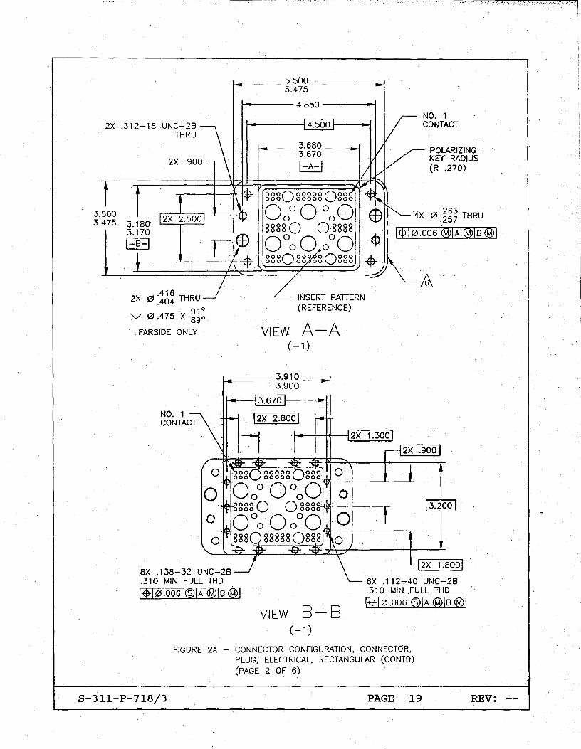
2X .900
3.500 3.475 3.180
3.170
~ ___ 5.500 ____ --./ 5.475
t------ 4.850 ---'---1.-1
4.500
t----- 3.680 _--11-1 3.670
I-A-I
000000000000
POLARIZING KEY RADIUS (R .270)
000 00000' 000 I
0 00 0 000 EB ·4X 0.
263 THRU
00060 0 0000 I .257
(50000°(5 -$- I 14-10.006 ®IA ®IB@I
0000 000 00000 ;IlL-~~~~~~OO~O~O~OO=O~O~OO~~~~
I-B-I
2X 0.416
THRU .404 . 91°
V 0.475 X 890
FARSIOE ONLY
8X .138-32 UNC-2B .310 MIN FULL THO
Ef10.006 ®IA @IB@I
INSERT PATTERN (REFERENCE)
VIEW A-A ( -1)
3.670
VIEW 8-8 ( -1)
6X .112-40 UNC-2B .310 MIN .FULL THO
Elf10.006 ®IA <wIB <WI
FIGURE 2A - CONNECTOR CONFIGURATION, CONNECTOR, PLUG, ELECTRICAL, RECTANGULAR (CONTO)
(PAGE 2 OF 6)
S-311-P-718/3 PAGE 19 REV: --

/16 l' 15 1 ""'\ 000000000000000
0000000000000000 000000000000000
0000000000000000 000000000000000
0000000000000000 000000000000000
0000000 0000000 000000·0 00 000 0 0 000000000000000
0000000000000000 000000000000000
0000000000000000 000000000000000
~@)@@@@@@@@@@@@@@@= • . @@.. •
@@ @ @O@ @ @@ @@@ '6' '6' . '6' '6' @@ @ @@@~ ~ ~ ~ ~@@@ @@@ ~@@@ @@@ @ @ © @ @@@ @@@ . @ @@@ @@ @ '6' '6'. '6' '6' @@@ @@@~ ~O~ ~@@@ @@ @ @ © © @@ @ @ @ @
@o@@@@@@@@@@@@@@ ~14 99
o 0 0 0 0 0 0 0 0 0 0 0 0·0 0 0 244' 0 0 0 0 0 0 0 0 0 0 0 0 0 0
2391
-2 SAME AS (-1)
EXCEPT INSERT PATTERN AS SHOWN
-4
-3 SAMEAS (-1)
EXCEPT INSERT PATTERN AS SHOWN
SAME AS (-1) EXCEPT INSERT PATTERN
AS SHOWN
FIGURE 2A - CONNECTOR CONFIGURATION, CONNECTOR, PLUG, ELECTRICAL, RECTANGULAR (CONTO) (PAGE 3 OF 6)
S-311-P-718/3 PAGE 20 REV: --
CIl I
w .... .... I
"tI I
-...J .... <XI "W
~ Gl t%j
t.J ....
fg <1 00
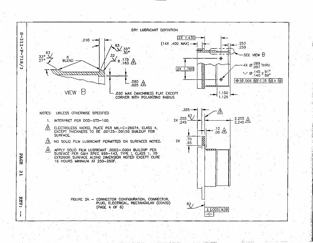
DRY LUBRICANT DEFINITION
33° 30°
12X 1.430~ (1 4X .400 MAX) ---j h
R .175 A .160 ill
VIEwB r.. .060 A .025 ~
.030 MAX (MACHINED) FLAT EXCEPT CORNER WITH POLARIZING RADIUS
NOTES: UNLESS OTHERWISE SPECIFIED
1. INTERPRET PER DOD-STO-1 00.
&. ELECTROLESS NICKEL PLATE PER MIL-C-26074, CLASS 4, EXCEPT THICKNESS TO BE .00125-.00150 BUILDUP PER SURFACE.
&. NO SOLID FILM LUBRICANT PERMITTED ON SURFACES NOTED.
ill APPLY SOLID FILM LUBRICANT .0002-.0004 BUILDUP PER SURFACE PER G&H SPEC 999-143, TYPE I, CLASS 1, TO EXTERIOR SURFACE ALONG DIMENSION NOTED EXCEPT CURE 16 HOURS MINIMUM AT 250-260F.
FIGURE 2A- CONNECTOR CONFIGURATION; CONNECTOR, . PLUG, ELECTRICAL. RECTANGULAR (CON TO)
(PAGE 4 OF 6)
2X
SEE VIEW B
4X 0"099 THRU .097
V 0. 145 X 91° .140 89°
RID ¢.006 ®rCT B ID ®l
-11.150 l 1.125
& y I .. 1 \.. • \ 2.255 A
2.245 ill
r·12 A
, ~ ...• 00 ill
~ cm~.l-r.-::-oo::-::5~1 A~I ~B I ~
'1"

til I
w I-' I-' I
"'0 I
-..J I-' ():)
......... w
~ Cil trJ
!IJ !IJ
E!1 <:
MATED VIEW
I... 11.00 MAX -I
k~-1lr--nllill III
F~~li ~I ·111
LJI" II 1 II
~--~-EMI BACKSHELL SHOWN FOR REFERENCE ONLY LJ
--ton II "In
--'~ .
DATE..,.LOT CODE PER MIL-STD-1285 EACH CONFIGURATION TO BE CONSECUTIVELY NUMBERED STARTING FROM 0000001
--I~ EMI BACKSHELL SHOWN II III LJ FOR REFERENCE ONLY
--~ .,-----...,.. .
CONNECTOR, RECEPTACLE SHOWN FOR REFERENCE ONLY J L 1.420 <D
1.360
GSFC PART NO ... X" TO BE:
700-42/3-1
700-42/3-2
700-42/3-3
700-42/3-4
ill CONNECTOR IS MATED WHEN DISTANCE NOTED BETWEEN FLANGES IS ACHIEVED
FIGURE 2A - CONNECTOR CONFIGURATION, CONNECTOR, PLUG, ELECTRICAL, RECTANGULAR (CONTD) (PAGE 5 OF 6)
'~II '~II

til I
w I-' I-' I
"tI I
....:J I-' (»
"w
~ I:%j
t\J W
~
CONTACT SIZE
WIRE OR CABLE SIZE
16-18.,..20
CONTACT SOCKET PIN
NASA
GPS20
COLOR CODE
BLUE
SEALING PLUG PIN
CRIMP TOOL NO.
POSITIONER I REMOVAL LOCATOR OR TOOL NO.
DIE NO. G&H PIN
INSERTION TOOL NO.
G&H PIN
PUSH TOOL NO.
G&H PIN
CONNECTOR SEPARATING
TOOL NO. G.&H PIN
16
GPS21
I 2 BANOS, NAS 1668-2 ~~-t~ 22-24-26 GREEN.
2 BANOS
M22520/1 '-01
M22520/7 . -01
1.122520/1 -02
1.122520/7 -04
882~94-001 882-94-001 I 882-'93-001
8 GPS10
8 12-14 GPSll
10 GPS16
RED 1 BAND
YELLOW 1 BAND
WHITE 1 BAND
882-214-002
!1
PICO CRIMP TOOL NO.
400B WITH LOCATOR NO. 4354-
~
PICO NO. 414DA-8N
~ PICO NO. 414DA-12N
& Plcd NO. 414DA':'8N
lis ASTRO TOOL
882-95-001 882-95-001 1882-91-001
882-80-001 (2 REaD)
RG-142B!U I RG-142B/U I GCP16 882-214-003
11 M22910/7 -1
612700 I 882-95-002
& 882-78-001
RG-393/U RG-393/U
GSFC 700-42/3-1-S
1 THRU II, 14 THRU 24, 32 THRU 39, 42 THRU 49, 57 THRU 67, 70 THRU 80
25, 26, 30, 31. 50, 51. 55, 56
12. 13. 40, 41, 68. 69
27. 28, 29. 52, 53. 54
FIGURE 2A
882-214-004 ASTRO TOOL GCP14 In M22910/7 I 613802 I 882-95-003
-1 &, CONTACT PATIERN IDENTIFICATION NUMBER
GSFC 700-42/3-2-S GSFC 700-42/3-3-S
1 THRU 20, 27, 29 THRU 38, I 1 THRU 244 43 THRU 48, 50 THRU 55, 60 THRU 65, 67 THRU 72, 77 THRU 86, 88, 95 THRU 114
21 THRU 26. 39 THRU 42. NONE 49. 5.6 THRU 59. 66. 73 THRU 76 •. 89 THRU 94
28. 87 NONE
NONE NONE
GSFC 700-42/3-4-S-2
1 THRU 54, 60 THRU 69, 75 THRU 85, 91 THRU 105, 111 THRU 164
55 THRU 59. 70 THRU 74. 86 THRU 90. 106 THRU 110
NONE
NONE
882-78-001
CONTACT SIZE
16
8
RG-142B/U
RG-393/U
CONNECTOR CONFIGURATION, CONNECTOR, PLUG, ELECTRICAL, RECTANGULAR (CONTO) (PAGE 6 OF 6)
~~====~~~==========================~======--------------~--==------------==------====
CONNECTOR MATING TOOL NO. G&H PIN
882-90-001 (2 REOD)
,;11
;1 i ;;j I .~
,:~~

2X 3.910 3.900
'--_ 3.500 ----.l 3.475
t--_ 3;688 1.255 3.680 200
A 1~_3.188_~ ~L. 3.180 E N--EE_-B-~-l
3.320 MAX [258
.245
2.170 2.140
I-A-I
MANUFACTURER'S CAGE CODE AND PART NUMBERS
4 EMI SPRING
A PROTECTIVE COVER (SHOWN IN THIS VIEW ONLY)
(-1 )
NOTES: UNLESS OTHERWISE SPECIFIED
1; INTERPRET PER DOD-STD-100.
£'G&H TECHNOLOGY., CAGE CODE 99447.
£ PICO CRIMPNG TOOL CO., CAGE CODE 29268.
& ASTRO TOOL CO., (FORMERLY BUCHANAN CRIMP TOOL PRODUCTS) CAGE CODE 581 64.
5. PART MATES WITH PLUG, GSFC S~311-P-718/3-X-S.
&.. BLUE COLOR BANDS ARE FOR VISUAL ALIGNMENT PRIOR TO MATING ..
7. CONNECTOR IS DESIGNED TO FUNCTION WITH EMI BACKSHELL KIT, GSFC GXX PER GSFC S-311-P-718/4.
8. TOLERANCES: .XX = ±.030 .XXX = ± .010
FIGURE 2B - CONNECTOR CONFIGURATION, CONNECTOR, RECEPTACLE, ELECTRICAL, RECTANGULAR
(PAGE 1 OF 5)
S-311-P-718/3 PAGE 24 REV: --

POLARIZING KEY RADIUS (R .250)
2X .312-18 UNC-2B THRU
2X .900
"--___ 5.500 ~-----t-l 5.475
~~-- 4.850 -----"l
~----J44~.5~00~--~
-----~ 00 00000 000 0000000000000
0 0°0 000 100000 000001 1000000001
0 0000°0 ~OOOOOO OOO~O 000 00 00 000 - - --
INSERT PATTERN (REFERENCE)
VIEW A-· A (-1)
3.670
12X 2.8001
4X 0 .263 THRU .257 .
1§t10.006 @IA@ls@1
2X 0.416 THRU .404 91°
V 0.475 X 890
FARSIDE ONLY
1 CONTACT 2X 1.3001---+--+---'
8X .138-32 UNC-2B .310 MIN FULL THO
1*10.006 ®IA @IB @I
VIEW 8-8 (-1 )
6X .112-40 UNC-'-2B .310 MIN FULL THO
1-$-10.006 ®IA (fJ)IB @I
FIGURE 2B - CONNECTOR CONFIGURATION. CONNECTOR. RECEPTACLE. ELECTRICAL. RECTANGULAR (CONTO)
(PAGE 2 OF 5)
S-311-P-718/3 PAGE 25 REV: --
T: !
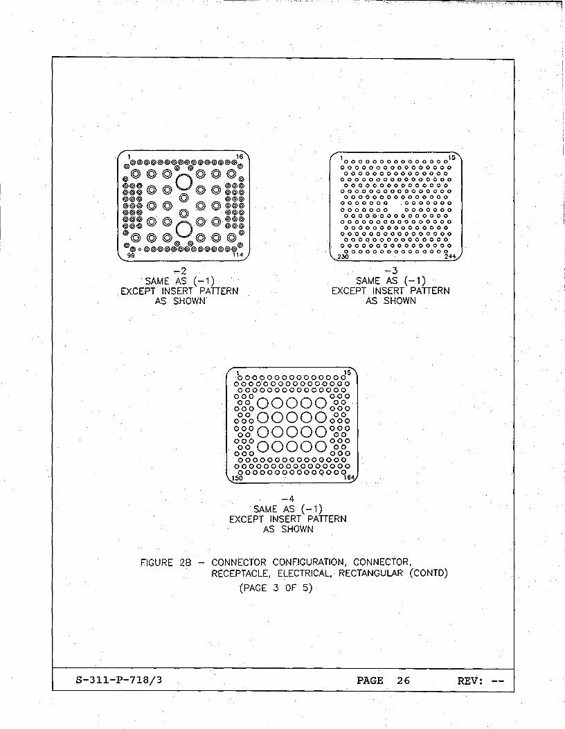
/ 1 . 16" @@@@@@@@@@@@@@@@
@ @ @ @
@@@@O@@@@
10000000000000001S\ 0000000000000000 000000000000000
@@@ '6' ~ '6'. '6'@@@ @@@~ ~ ~ ~@@@ @@@ @ @@O @@@ @ @ @ @@@@ @@@. @@@@ @@@ '6' '6' fi '6' @@@ @@@~ ~O~ ~@@@ @@@@. @@@@ @ @@ @
@o@@@@@@@@@D@@@@
o 0 0 0 0 0 0 0 0 .0 0 0 0 0 0 0 000000000000000
o 0 0.0 0 0 0 0 0 0 0 0 0 0 0 0 000000000000000
0000000 0000000 0000000 0000000 000000000000000
0000000000000000 000000000000000
0000000000000000 000000000000000
0000·000000000000 000000000000000
\. 99 114...; 230 ·241/
-2 SAME AS (-1)
EXCEPT INSERT PATIERN AS SHOWN
-4
-3 SAME AS (-1)
EXCEPT INSERT PATIERN AS SHOWN
SAME AS (-1) EXCEPT INSERT PATIERN
AS SHOWN
FIGURE 28 - CONNECTOR CONFIGURATION, CONNECtOR, RECEPTACLE, ELECTRICAL, RECTANGULAR (CONTO)
(PAGE 3 OF 5)
S-311-P-718/3 PAGE 26 REV: --

CIl I
w I-' I-' I
'"d I
-..J I-'
·00 -....... W
~ G'l t%j
t\.)
-..J
~ 00
MATED VIEW
I" 11.00 MAX "'-1
I.. 4.40 MAX .. I
~--ll '--.... ~I ~II r--tn) nlll II II ... a..~ I.Cf~u I 1IIIIn
GSFC PART NO. "X" TO BE:
700-42/3-1
700-42/3-2
700-42/3-3
700-42/3-4
DATE-LOT CODE PER MIL-STD-1285 EACH CONFIGURATION TO BE CONSECUTIVELY NUMBERED STARTING FROM 0000001
~I . L_~I g±~ ~~II~_J~I I
II fu' ,6 ""xlll . . u.~~ ~~K' . .
. ~ I ~ I~ I~ .
I r r - \Q:J I ~~~ ~~~II ~ - -I' .' . EMI BACKSHELL SHOWN LJIIIII II ~6:~ 1~~~1I1 .. IIIII~ . FOR REFERENCE ONLY
III I, . zliio: Iz~ffill p ;1 III ~-- 8i3~ ~8tlb--_~
EMI BACKSHELL- SHOWN FOR REFERENCE ONLY
CONNECTOR, PLUG SHOWN fOR REFERENCE ONLY J
ill CONNECTOR IS MATED WHEN DISTANCE NOTED BETWEEN FLANGES IS ACHIEVED
L 1.420 ill 1.360
FIGURE 28 - CONNECTOR CONFIGURATION, CONNECTOR, RECEPTACLE, ELECTRICAL,RECTANGULAR (CONTD)
(PAGE 4 OF 5)
(Jl I
w I-' I-' I
It! I
...J I-' 00
.......... w,
~ Cil t:r:I
l\.)
00.
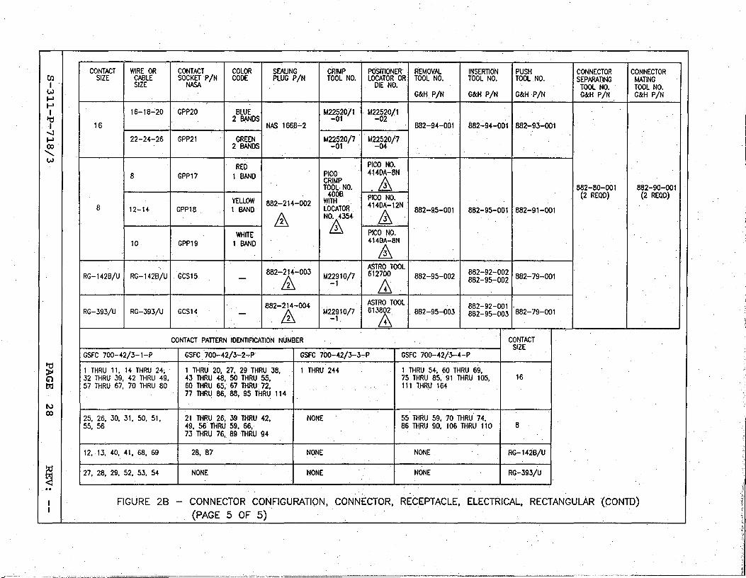
fgl <: 00
CONTACT WIRE OR CONTACT COLOR SEALING CRIMP POSITIONER REMOVAL INSERTION PUSH CONNECTOR CONNECTOR SIZE CABLE SOCKETP/N CODE PLUG PIN TOOL NO. LOCATOR OR TOOL NO. TOOL NO. TOOL NO. SEPARAnNG MATING
SIZE NASA DIE NO. TOOL NO. TOOL NO. G&H PIN G&H PIN G&H PIN G&H PIN G&H PIN
M22520/1 16-18-20 GPP20 BLUE M22520/1 2 BANDS -01 -02
1 882-94-001 1 882~94-001 1882~93-oo1 16 NAS 166.8'-2
M22520/7 . ·1.422520/7 22-24-26 GPP21 GREEN 2 BANDS -01 -04
,
I PICO PICO NO.
RED I 8 GPP17 1 BAND 414DA-8N
CRIMP .& TOOL NO. 1882-80-001 I 882-90-001 400B. PICO NO. (2 REQD) (2 REOD)
YELLOW 1882-214-002 WITH 8 1 12-H 1 GPP18 LOCATOR 414DA-12N
1 BAND
& 882-9.5-001 882-95·-001 882-9.1-001
fA N&354
WHITE I PICO NO. 10 1 GPP19 1 BAND 414DA":8N
& ASTRO TOOL
RG-142B/U I RG-142B/U I GCS15. I 882-.&,-003 I M2~i'0/7 I 612,& I 882-95-002 I ~~~=~g=gg~ 1882-79-001
RG-393/U 1 RG-393/U 1 GCS14 1882-214-004
fA ASTRO TOOL I I 882-92-001 613£ 882-95-003 882-95-0031882-79-001
CONTACT PATIERNIDENTIFlCATION NUMBER I CONTACT SIZE
GSFC 700-42/3-1-P GSFC ·700-42/3-2-P GSFC 700-42/3':'3-P GSFC 700-42/3-4-P
1 THRU 11, 14 THRU 24; 1 THRU 20, 27, 29 THRU 38, 1 THRU 244 1 THRU 54, 60 THRU 69, 32 THRU 39, 42 THRU 49. 43 THRU 48. 50 THRU 55. 75 . THRU 85. 91 THRU 105. 16 57 THRU 67. 70 THRU 80 60 THRU 65. 67 THRU· 72. 111 THRU 164
77 THRU 86. 88. 95 THRU 114
• 25. 26. 30. 31. 50. 51. 21 THRU 26. 39 THRU 42, NONE 55 THRU 59. 70 THRU 74. 55. 56 49. 56 THRU 59, 66. 86 THRU 90. 106 THRU 110 8
73 THRU 76. 89THRU 94
I 12. 13. 40. 41, 68. 69 28. 87 NONE NONE RG-142B/U
127. 28. 29. 52. 53. 54 NONE NONE NONE RG-393/U
FIGURE 28 CONNECTOR CONFIGURATION, CONNECTOR, RECEPTACLE, ELECT~ICAL, RECTANGULAR (CONTO)
(PAGE 5 OF 5)
~ L,


![Printed Circuit Board ConnectorsPrinted Circuit Board Connectors Printed Circuit Board Connectors Table of Contents 6001 MICRODOT Rectangular .050 [1.27] Connectors Twist Pin 24 Gauge](https://img.pdfslide.us/doc/110x75/600734f9ad8a1c5be53fba12/printed-circuit-board-printed-circuit-board-connectors-printed-circuit-board-connectors.jpg)