Embed Size (px)
DESCRIPTION
Rycom Model 2174 Frequency Selective Voltmeter ~ Maintenance Manual, 1968.
Citation preview

MOD E L 2 1. 7 4
SELECTIVE VOLTMETER
Serial No. J"'·7
Ij
®
MODEL 2174
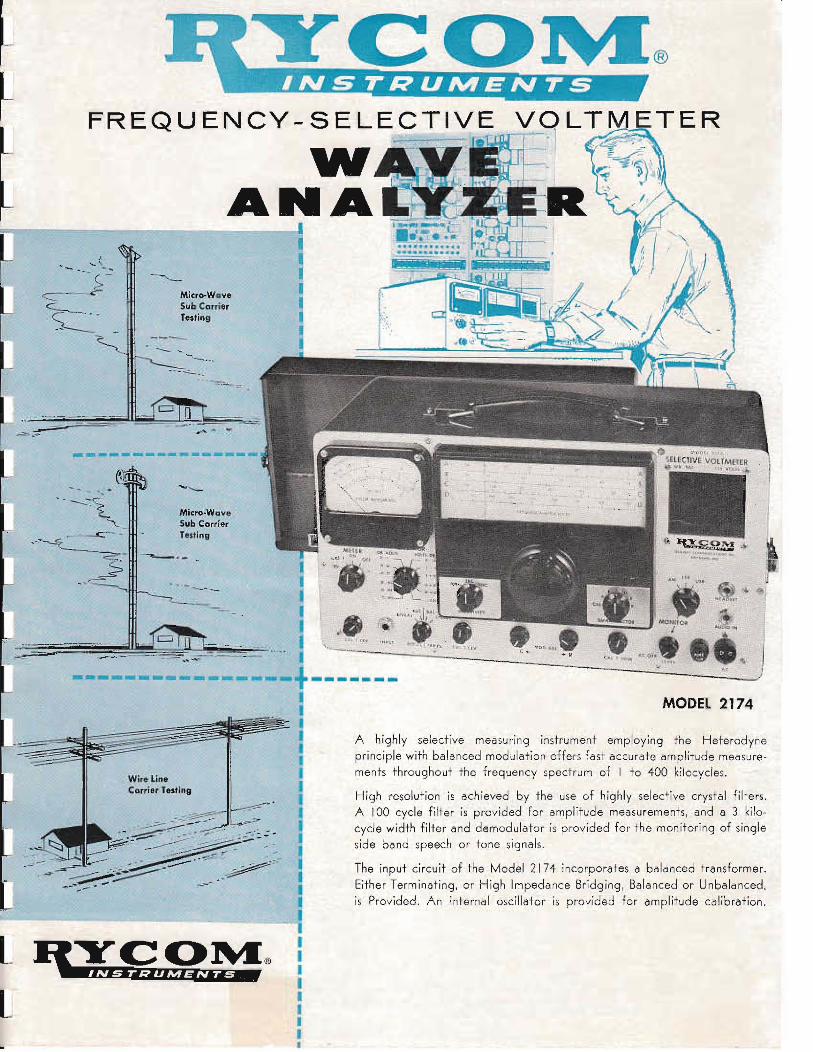
A highly selective measur'ing instrument employing the Heterodyneprinciple with balar1ced modulation offers fast accurate amplitude measurements throughout the frequency spectrum of I to 400 kilocycles.
High resolution is achieved by the use of highly selective crystal filters.A 100 cycle fiHer is provided for amplitude measurements, and a 3 kilocycle width filter and demodulator is provided for the monitoring of singleside band speech or tone signals.
The input circuit of the Model 2174 incorporates a balanced transformer.
Either Term inating, or High Impeda nce Bridg ing, Balanced or Unbalanced,is Provided. An internal oscillator is provided for amplitude calibration.
~. ......
Micro-WctveSub (:anierTltsling
Micro-WaveSub C:cmiltrTllstlllB
--- -
FREQUENCY - SELECTIVE
WANA
-
. ...(- --- ....(-?
---

MODEL 2174 FUNCTIONAL BLOCK DESIGN
BAND WIDTHill DBMCPS
~I
IN
~ J 1(1 DEM-----+-1_ 400 KC 1
Fe450KC
500to
900KC
..---------- ...... --- ------.. -.-
C. SPECIFICATIONS /..._~----- ----------
Frequency Range: I Kc 10 400 KcLevel: -72 dbm to +32dbm (full scole) AT. 600 ohm.Accuracy: ± .5db From -80 10 +32dbm; 1 to 400 Kc.Selectivity: 6db Down 80 cycles off: 60db down 480
cycles off.
Spurious Response: Below 60db.
Intermodulation: 3rd ond Higher Orders Below 60db.
Power Requirements: 115V, 50/60 cycle$ 48 Wott$
Weight: 28 LBS.
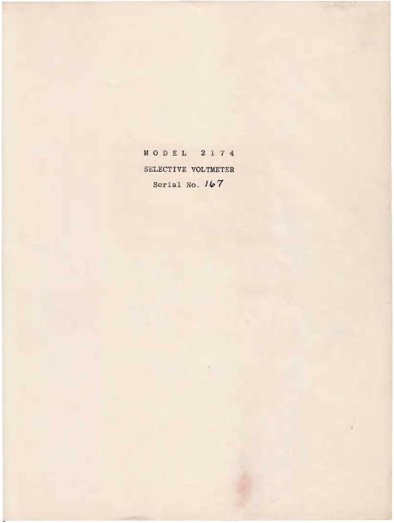
F LTER RESPONSE CURVES ..• MODEL 2174
II\ V
i !IOOCPS 1\ J
'I \ ) I
Ie 9.1' 54 J 2 I a It] 4 S , } I ,rHlIUI~CY I_ IlILOCYClU
• 11 I I
0I I 1~
0! I
I', I -(.•
,! " \ YI 1\1 I I
• 1\, I t-+.!/: i ; i• i
,1 i I~~C ~.: i I I,
1\.1 1 I/' I ! ."
• : i i N~i V ! i ! i "I
..
• I,•" I
,,Ii :, ,
,l'
,ut, I
" !I
" !• -11 II 10 ! I J • ~ ~ ) 2 1 g J 1 ] ~ ~ , I • 9 It 11
FUQU[,lICT til ';1~GelClrs
• ,N Il'· I 'j--\ '\Of-+-
I 'Ii. ill\m 1:/- I L.-Y !, \0
,ill N·'1 \ I 1\ i I\'1~
1•~ ! I
,II
I I0 T,· I I! !
•""!'- I
I
L.-: I Ii I~~' ! I, I
! !'- I U1t\! I ! y' I !I,
N 1\1 -y i,1
,
" - " J t \:. i I: i " ~ I,lOa100 a 100
fRIOUUC! 'N CUES200
'Bcsndwidth100 CPS FILTER6db - 159 Cycles
60db - 920 Cycle.3KC FILTER
3db - 2140 Cycle.45db - 4200 Cycle.10KC FIlTER
3db - 4460 Cycle.45db - 24,950 Cycle.
• Average Measure
ALSO MANUFACTURERS OF:
LARGE SCREEN OSCillOSCOPESPRINTER MOTOR CONTROLLERCARRIER TElEPHONE & TElEGRAPH lERMINALSCUSTOM TOROIDAL - REACTORS & TRANSFORMERSFILTERS: LOW PASS - BAND PASS - HIGH PASSCUSTOM TEST EQUIPMENT
A Division of
RAILWAY COMMUNICATIONS, INC.935l E. 59th Street - Raytown 33, Missouri - Phone: Fleming 3-2100

. ,.. ' .~
INSPECTION
This instrument has been thoroughly tested and inspected beforeshipment.
The instrument should be inspected for damage as soon as it isreceived. If no damage is apparent, test for operation according tooperating instructions in this manual.
SUMMARY
The Selective Voltmeter is a highly selective instrument formaking voltage measurements of frequenci.es from I to 400 kc (below1 kc with caution) varying in level from -90 to f32 dbm (30 voltsmaximum without external attenuator). Zero dbm reference is 1 milliwatt of power (or .775 volts) in a 600~ load. The input signal isattenuated to the proper value by the attenuator, amplified anddemodulated to 500 kc by a shunt type dem.odulator and variableoscillator. This 500 kc signal passes through a sharp crystal filter,then is amplified and detected. The de output is applied to a 200microampere meter. The meter has dbm and voltage scales and is calibrated to indicate the signal level at the instrument's input jack.A wide crystal filter or broad tuning may be selected for moni~oring.
In this use the 500 kc amplifier output is demodulated by a shunttype demodulator and crystal oscillator for upper or lower sidebands,by a conventional diode detector for AM signals, or by slope detection of FM signals. An input jack has been provided to the audioamplifier of the monitor for monitoring audio voice channels. Aninternal calibrating circuit is provided so calibration can be madeor checked as desired.
DESCRIPTION
GENERAL
A block diagram and schematic drawing are included in this manualfor reference while reading the text.
All symbols referred to such as (VI) (X9) (R53) or capitalizedsuch as CAL 1 LEV or METER are stamped on the chassis or front panelof the instrument and/or used in the schematic drawing.
The input circuit contains a condenser (Cl) to block DC potentials, a transformer in the input of 3002 filter so that measurementscan be made on balanced circuits, a 400 kilocycle lowpass filter(3002) and an attenuator. The input impedance and balance or unbalance is controlled by 600--10K ~~ switch (Sl). The attenuator(ATTENUATOR) properly adjusts the input signal applied to VI andhas a CAL position used in calibrating the instrument. The isolationamplifier (VI) feeds a shunt type balanced demodulator (V2) whosebalance is controlled by MOD BAL controls C & R. A variable frequency LC oscillator (main oscillator, 1/2 V3) and phase inverter(1/2 V3) supplies carrier frequency for demodulation. This frequency
I

is controlled by the main tuning condenser (C36) , BAND SEL switch(S3) and a trimmer condenser (CB3) CAL 2 TRIM. The 100 cps or 3 kccrystal filter (Xl through 4 & Tl or X5 through 8 & T2) or 10 kcbroad coupling (C26 and 29) passes the lower sideband of modulation.The 500 kc IF amplifier (V4 & V5) feeds both the measure (V6, D3-4)and monitor (V8,9&10) sections of the instrument. The IF amplifiergain is adjusted by CAL 2 LEV (R37). The meter circuit amplifier(V6) feeds a series shunt type meter 1'6 :~.ti fier (D3 & D4) whose output indicates on a 200 microampere meter "alibrated in dbm and volts.The IF isolation amplifier (V8) feeds a ··B ..~ies type demodulator (Dl,D2) for monitoring lower sideband LSB or upper sideband USB signals(MONITOR switch on LSB or USB and SELECTIVITY switch on 3 kc).The carrier for this demodulator is supplied by a crystal controlledoscillator (1/2 V9). For monitoring amplitude modulated signalsor slope detection of FM signals, this oscillator is made inoperativeand diode D2 removed thus the circuit operates as a conventionaldiode detector (MONITOR switch on AM and SELECTIVITY switch on 10kc). The resulting audi0 signal passes through the RC filter (R40,C57,C58) and amplifier (1/2 V9,VIO), to the speaker or a headsetplugged into the HEADSET jack (J3). The audio output amplitude iscontrolled by the potentiometer MON LEV (R42).
An audio signal may be amplified by inserting it in the AUDIOIN jack just ahead of the audio amplifier (1/2 V9 & VIO).
A 30 kilocycle LC tuned oscillator (1/2 V7) coupled to acathode follower (1/2 V7) is used to furnish the calibration signal.The potentiometer CAL 1 LEV (R55) adjusts the calibrate oscillatoroutput. Plate power is supplied to the calibrate oscillator onlywhen the BAND SEL switch is in the CAL position, thus it is inoperation only during calibration.
Plate power is furnished by a bridge type full wave seleniumrectifier (SRl-SR4). A voltage regulator tube VII stabilizes theplate supply to all circuits except the monitor section.
The filaments are 50 volts DC above g~ound to prevent heaterto cathode leakage and to eliminate 60 cps modulation which mayoccur in VI and V2.
INPUT
The input impedance is 600 ohms (600~) or bridging (10K) asselected by the 600-l0K switch 81. The input circuit may beswitched from balanced (BAL) to unbalanced (UNBAL) as desired oneither input impedance. In the bridging position (10K) the inputimpedance remains high enough to cause negligible loading of lowimpedance circuits. The input impedance is approximately 10,000ohms from 1 to 30 KC, gradually falling to a.pproximately 5000~
at 400 KC.
An external signal is connected to the input circuit by meansof a two conductor phone plug in INPUT jack. The sleeve of this

jack is insulated from the front panel, thus isolating it fromchassis ground during balanced measurements.
ATTENUATOR
The attenuato:!' provi.des 0 to 100 db of attenuation for measuring signals between -68 and ~32 dbm (full scale meter indication).The CAL position is connected to the voltage divider of the calibrateoscillator output for calibrating the isolation and IF amplifiers.
FREQUENCY
The main oscillator is varied from 501 to 900 kilocycles byBAND SEL switch and main tuning dial to measure frequencies of 1
to 400 kilocycles respectively as indicated on the frequency dial.For example, a signal of 17 kc is fed into the instrument. TheBAND SEL switch is set on A and frequency dial tuned to 17 kc.The main oscillator is now oscillating at 517 kc and the lowersideband of demodulation is 500 kc which is the center frequencyof the crystal filter. ~Jning for calibration (BAND SEL On CAL)is separate from the main tuning dial and adjusted by the CAL 2TRIM control. This greatly simplifies meter calibration and calibration checks if desired while using the instrument. Since theCAL 2 TRIM control remains in the tank circuit on all bancls it canbe used as a frequency vernier when making measurements. This,however, temporarily disturbs the frequency calibration of theinstrument. When making an internal ca.libration of the instrumentthe main oscillator frequency is automatically recalibr"ated by theCAL 2 TRIM control at 30 kc.
The trimmers C40,42,44,46,48 & 88 are used to set the frequency of each band (A,B,C,D,E & F.) C38 is used to set thecalibrate frequency tuning. These calibrations are made withCAL 2 TRIM at mid range.
MODULATOR BALANCE
When measuring frequencies below 1 kc, the demodulator mustbe balanced to prevent erroneous readings due to main oscillatorfrequency passing through the crystal filter and being measuredalong with the desired signal.
The demodulator is balanced with the main oscillator at 500kc (frequency dial at zero) so the carrier (oscillator frequency)will pass through the crystal filter (100 cps bandwidth) andindicate on the meter. C & R are adjusted for minimum meterindication thus a minimum carrie:r frequency (carrier leak) at themodulator output.
The two controls C MOD HAL R control the balance of the maindemodulator. The C control (C80) balances the capacity componentand the R control (R24) balances the resistive component.
3
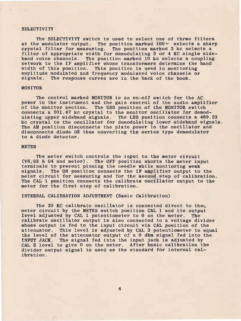
SELECTIVITY
The SELECTIVITY switch is used to select one of three filtersat the modulator output. The position marked lOON selects a sharpcrystal filter for measuring. The position marked 3 kc selects afilter of appropriate width for demodulating 3 or 4 KC single sideband voice channels. The position marked 10 kc selects a couplingnetwork to the IF amplifier whose transformers determine the bandwidth of this position. This position is used in monitoringamplitude modulated and frequency modulated voice channels orsignals. The response curves are in the back of the book.
MONITOR
The control marked MONITOR is an on-off switch for the ACpower to the instrument and the gain control of the audio amplifierof the monitor section. The USB position of the MONITOR switchconnects a 501.47 kc crystal to the monitor oscillator for demodulating upper sideband signals. The LSB position connects a 489.53kc crystal to the oscillator for demodulating lower sideband signals.The AM position disconnects the plate power to the oscillator anddisconnects diode D2 thus converting the series type demodulatorto a diode detector.
METER
The meter switch controls the input to the meter circuit(V6,D3 & D4 and meter). The OFF position shorts the meter inputterminals to prevent pinning the needle while monitoring weaksignals. The ON position connects the IF amplifier output to themeter circuit for measuring and for the second step of calibration.The CAL 1 position connects the calibrate oscillator output to themeter for the first step of calibration.
INTERNAL CALIBRATION ADJUSTMENT (Basic Calibration)
The 30 KC calibrate oscillator is connected direct to themeter circuit by the METER switch position CAL 1 and its outputlevel adjusted by CAL 1 potentiometer to 0 on the meter. Thecalibrate oscillator output is also connected to a voltage dividerwhose output is fed to the input circuit via CAL position of theattenuator. This level is adjusted by CAL 3 potentiometer to equalthe level of the attenuator output of a 0 dbm signal fed into theINPUT JACK. The signal fed into the input jack is adjusted byCAL 2 level to give 0 on the meter. After basic calibration thedivider output signal is used as the standard for internal calibration.
4

OPERATING INSTRUCTIONS
GENERAL
Operation of the Selective Voltmeter is divided into twomajor functions, tha.t of measuring signals as indicated by themeter and that of monitoring carrier and audio voice bands orsignals.
All controls, signal input, audio input and output jacks,and power connections are on the front panel of the portableinstrument. The power connection may be on the back of the rackmounte~ instrument.
The power required is 48 watts 50/60 cps, 115 volts. Connection is made to the instrument with the cord furnished in thereceptacle (AC). The power switch is located on the MONITORLEVEL control where the off position is indicated (AC OFF) .
DEMODULATOR BALANCE
Balance the demodulator as follows with the input signaldis.connected (for measuring frequency below 1 kc).
a. Switch positions.BAND SEL on A FREQUENCY dial on 0 METER on ON
b. Adjust MOD BAL controls C and R to obtain a minimummeter reading.
Note: If meter reads off scale adjust FREQUENCY dialup scale for full scale meter reading, adjust C andR for preliminary balance (minimum meter reading).Return FREQUENCY dial to zero frequency (maximum meterreading) and rebalance. Repeat if necessary. At finalbalance it should be possible to tune across 0 frequency wi.th a maximum meter reading of -10 to -20 db.
c. If a balance cannot be obtained within the limits ofthe C&R control on the fr~nt panel, coarse C&R balancecontrols are provided inside the main osc assembly.When the front panel C control pointer is in the 3or 9 o'clock position, the C eontrol is at or out ofits control limit. To adjust the coarse controlsremove the unit from the case. The coarSe controls-are directly under the holes marked C&R. Set theC&R front panel controls in mid-range and adjust C&Rcoarse controls until an on scale balance is obtained.Complete the balance with the front panel controls.
5

· balancs has cau ed
_..1'" d8c.;::.:::.~ 0'" balan e n .;::;ded j.G c13penCSl1t on the selactivity oft ~ rr73·~u~ ~il-~e~ a~d t~la freqLsncy Q3adured.
he l' C cp...,a Fe', C!~) a..~
rys ,- al f:l.1 ;;er is dOVJ~1 moro tf.lan 2(; 0.0 at 300 cps off~~GG cps of~, ~~us a J ~b ~a~a~ca will caUGe negli~~~ 0
asuring a 30D cps or hj.e~er "tone.
A qci :< cLec.~ :i.s to 1:U e in t:-:8 d-8olred signal, reli10V8 ~c:he j.nputand bsst' 8 1:: __ ffi'cte e~...c1:~ i1e: (11;i8 ·~o ~~a.~~~;"'81~. 1 J: i -;.: :t~ less tb.ana eE:-~~.nlat~~ J5· dD y ti1~3n t1Y 1~8ac~~LJ.~e a::::>\re -IS do v!:'Lil '08 aff.ccteclless -;:~."'JOa... .],. r1b. l~TOT:~: vo 11Ct St~t tI-la ~neter zarc, o:~ 0 ''tI0 .... t,n.1\~J2 nleC3I' Z~l.~O is usee] iOl'" ~ne-c214 'Ll"aC.l.\::?_11g at ..-lJ db.
A'~ low ~alaDca, a double pea~ or erratic meter· fluctuations mayble l1C'"·-ed.. T..18Se do 110t 119ceccal":; 1;' i11d~... cate '~rG' tb_,e :t:( t~29
inst:i1 lw;,}n.t performs sat::"s:;-'actor:::':'y w;.:,Bn measur;~ne: a to e.
The tube used as VI is critical in date min~ng t~e degree il~nce ob~ainable princ~pa~ly dU8 to ~eater and ca~~od8 1 ga.
US "=lo ~ ~"':::l. ~C'I'" '.:::Jo~" tZ~··.''',q -.... "11'"",~ r:r a· ~·~.f~l /r.:.~,:,.'"!,~ -Po 1" ~")~'\•. r.Q"r_ ~---a;_~L·~.~e ..~ ..- ......,_ ~ u \.J ~.l..., '-.L~t...i_ U. ......'-' ,,~>- 'l..,;I'~_,_._''''' '_ ......-~_~v ..., _ ......
Turn t;18 1l,10n::r'i.'OR-. ,EVEL down -to m:l.n:~mum Wih'311 balancing.

INTERNAL CALIBRATION
Calibrate the instrument as follows.
CAL 1a. Switch positions.
BAND SELECTOR to CAL ATTENUATOR to CALb. Adjust CAL 1 LEVEL to give zero on meter.
METER to CAL 1
CAL 2a. Switch positions.
BAND SELECTOR to CAL METER to ON MONITOR to AMATTENUATOR to CAL SELECTIVITY to lOON
b. Adjust CAL 2 TRIM to peak meter.c. Adjust CAL 2 LEV to give zero on meter.
This completes the calibration and the instrument is ready for use.
INPUT CIRCUIT SELECTION
The input impedance may be 600~ unbalanced or balanced; bridgingunbalanced or balanced, as selected by the 600~--10~ switch onUNBAL or BAL.
The INPUT jack takes a two conductor phone plug.
FREQUENCY SELBCTION
Frequency selection is made by means of the three controls onthe black FREQUENCY dial cover. The frequency to be measured istuned in by the large center knob and position A,B,C, etc., of theBAND SEL switch.
The SELECTIVITY switch 'selects the crystal filter band widthto be used. Use the 100 cycle position for precise measurements.The 3' kc and 10 kc position for monitoring. 10 kc position maybe used for measuring above the first band.
AMPLITUDE MEASu~EMENT
Connect the signa,l to be measured to the INPUT jack. (CAUTION:see overload paragraph).
a. Switch positions.BAND SELECTOR to desired band SELECTIVITY to lOONATTENUATOR to proper level MONITOR to AM (for preciseMETER to ON measurements)
b. Adjust FREQUENCY dial to desired frequency and formaximum meter indication.
c, Add meter indication and attenuator position algebraicallyto obtain amplitude of signal being measured.
6

(.'sl ·w ::- !~c~: 'out 200 cps 0",-_
.·:io~:. 1 f a C,DDJ". cil" ::.ui ~ 'i:,arm:i_nu'i,; on _8
~:>2 3 .. ::'''8Ci) usc- an '':'''~''''J''. res::or across·~;J.e i.n.s~rument inp ·C.
~~~ darned ~a~or mus~ ~e ba~a~c0d to prevenc erroneous me~er ~lldica
iioil due '1:.0 :28,.1 ler l'2aIt. ([:20 1)2~:nodu:"acor Balanc'..:l paragraph).
( '-"1t::>r'i a1 '1.100~"''...,; .-.. - :, P. l7:J..,..-2CO
ElLa.b. adjust CAl. 1 LEVEL to give Z0":''''O ~1 me ~:er
n l' " -of; 7'
.. 1l .; -..:; l; 1/....II II .. - ;:
<
OVERLOAD
The amplifiers of this instrument overload before the metermovement is damaged on mod.erate overloads--however excessive orprolonged overloads should be avoided,
Ampli tudes of .~f,20 dbm or higher should not be left appliedtc the instrument for long'er than a minute or two since the inputcb:cuit may heat, If "l20 dbm or higher amplitude is to be connected continuously~ a suitable pad should be connected ahead ofthe instrument to reduce the level below ~20 dbm.
LOW AMPLITUDE SIGNAI.S IN PRESENCE OF HIGH AMPLITUDE SIGNALS
Ove~loading is reduced by introducing attenuation to the.i.n.pnt signals, Therefor when measu:r'ing a low level signal,when high levels are also present, the more accurate readingwill be made when the attenuator step is selected to give a meterreading on the lower 10 db section of the meter scale. Whenmeasuring circuits <on which amplitudes are not approximatelyknown~, it is suggested that the entire spectrum be first scannedto determine the highest amplitude signals present. This' willindlcate the lowest level signals which may be accurately measured.When highest to lowest lev.els exceed 45 db, some inaccuracy dueto overl.oad or intermodulation ma.y be suspected. When measuringha:r-monics of a s::tngle fre.q.uency input., accurate readings may bemade 50 db or less for 2nd and 60 db or less for 3rd harmonic,
In a.ny ease, when a low level signal is being measured, ifthe attenuator sw~tch is changed by 10 db and the meter readingalso changes 10 db, the measurement can be considered accurate.
When many input signals are present, no simple rule can befollowed, as the overload point is determined by the peak envelopeof the co.mbined signa.Is whi(:h ma.y va.ry with their ampli tude and phase.
7

CARRIER MONITORING
The Selective Voltmeter may be used to monitor lower sideband(LSB) , upper sideba.nd (USB), amplitude modulated (AM) or frequencymodulated (FM) signals. Use the 3 kc position of SELECTIVITYswitoh aGove 3 kc only and the 10 kc position above 10 kc only.
I. Upper and lower sid.eba.nd monitoring.·a. Connect the input jack to the circuit to be monitored.b. Switch positions.
SELECTIVITY to 3 KCFREQUENCY DIAL & BAND SEL switch to midband frequencyof the sideband
MONITOR switch to LSB or USB as requiredMONITOR LEVEL--adjust as needed.
If the voice or signal from the speaker (or headset if used inHEADSET jack) is weak turn the METER swi'cch off and the ATTENUATORdown until the desired level is rea.ched.
2. AM monitoring.
To monitor AM signals feed signal in INPUT jack, turn theselectiVity to 3 kc or 10 kc, set the MONITOR switch to AM, tunethe FREQL~NCY dial to the carrier frequency and adjust the amplitude as for single sideband signals.
3. FM monitoring.
To monitor FM signals by slope detection feed signal in INPUTjack,turn the SELECTIVITY switch to 10 kc, set the MONITOR switchto A~, adjust the frequency dial for best reception (one side ofthe selectivity curve) and a.djust the amplitude as for singlesideband signals.
AUDIO MONITORING
The audio section of the monitor circuit may be used as avoice frequency amplifier if desired by inserting the signal inthe AUDIO IN j ac.k. The Olltput ampli. tude is controlled by theMONITOR LEVEL control.
8

MAl NT'ENANCE
GENERAL
Most of the components used in the construction of RYCOMinstruments are standard parts obtainable from local suppliers.Precision components may be purchased from the manufacturer.All repla,cement parts are available from RYCOM.
For various reasons inked change will occasionally appearin the instruct,ion book text) ~'Cl..1:'t,s l:i.'i;..t 'il.:nd ~:ra:~in.%s. Con'tin:uedeffort ~s be1ng made to improve circuitry and use better components.D"uring the test procedure~ individual adjustments are made toobtain optimum ope!"ation. Parts pro'Curement difficulties occasionally require substitution of diffe:t'ent but equivalent parts.
When ordering parts be sure to specify the instrument serialnumber as well as the instrument model number and individual partnumbe]~o This will insure receiving the correct replacement partswi th a min.imum of dela;)~.
Normal maintenance involves ~eplacement of tubes, fuse andpilot lights.
The frequency dial lights are aCiCessible from the front byremoving the knobs and black dial cover.
To remove the instrument from the case for maintenance,],,"emove ~!!.~l the !l~.!, !!-e~<!, ~.cr,-ews around edge of the fron t panel.
BASIC AMPLITUDE CALIBRATION
Tube replacement or aging may cause some error in meterl.udication which is not expected to be more than ±1/2 db. Thiscan be corrected by basic recalibration of the instrument asdiseussed in "Cca,libration" para,g:rraph of the description andgiven in step form below.
1st stepa, Connec.t an external signal of about 45 kc of 0 dbm
amplitud.e to the input jack (NOTE~ use a precisionmeter to determine the 0 d.bm amplitQde).
b " Swi tch pasi tlons •ATTENl.TATOR on 0 MONITOR on AMMETER on ON BAND SEL on BSELECTIVITY on lOO(\) FREQUENCY dial to give peak
indication on meterc. Adjust CAL 2 LEV to give 0 on meter.
2n.d stepa" CAU'fION do not c.hange CAL 2 LEV.b, Swi.tch posi£I&ns.
METER on CAL 1 BAND BEL on CALc. Adjust CAl, 1 LEV to give 0 on meter.
9

3rd stepa o CAUTION do not change CAL 1 LEV or CAL 2 LEV.b. Switch positions,
METER on ON MONITOR on AMATTENUATOR on CAL BAND SEL on CALSELECTIVI TY on 100 rv
c. Adjust CAL 2 TRIM for peak meter indication.d. Adjust CAL 3 control located behind the meter to give
zero on the meter'. (Loosen and retighten locking nuton CAL 3)
FREQUENCY CALIBRATION
Frequency recalibra,tion is made each time CAL 2 TRIM controlis adjusted for pea.k meter indication during calibration, howeverif the frequency tuning drifts more than 500 cps it may be desirableto recalibrate the bands that are off and all lower frequency bands.If CAL 2 TRIM gives a peak indicatioB with the knob pointer in the3 or 9 o'clock position, the oscillator in CAL position has driftedout of the range of the control and the CAL position should be recalibrated.
An accurate 10 to 400 kc oscillator or oscillator and counterwill be required to recalibrate the frequency dial (main osc).
Remove the case, turn on the power and allow the instrumentto warm up for 20 minutes. Connect the external oscillator to theINPUT jack. Set the CAL 2 TRIM control in 12 o'clock position.Set the attenuator control to level used, BAND SEL and frequencydial to position indicated in the chart below. Adjust the trimmerindicated in the chart to obtain a peak meter indication.
A'fTN BAND SEL
Level used FTf E" D" C" B" A
CAL CAL
FREQ DIAL ADJUST TRIMMER
350 kc F (in 500 kc osc)230 kc E (on top of chassis)160 kc D "100 kc C "50 kc B "10 kc A "
CAL "
The capacitors in the main oscillator are accumulatively addedto the cireuit as the BAND SEL switch is rotated from F to CAL,thus frequency calibration must be made in the order listed above.
I F STAGE RETUNING
In the event CAL 2 LEV amplitude cannot be turned high enoughto calibrate the instrument j tUbe replacement, retuning the IFstage transformers j or retuning the crystal filters will be necessary.
10
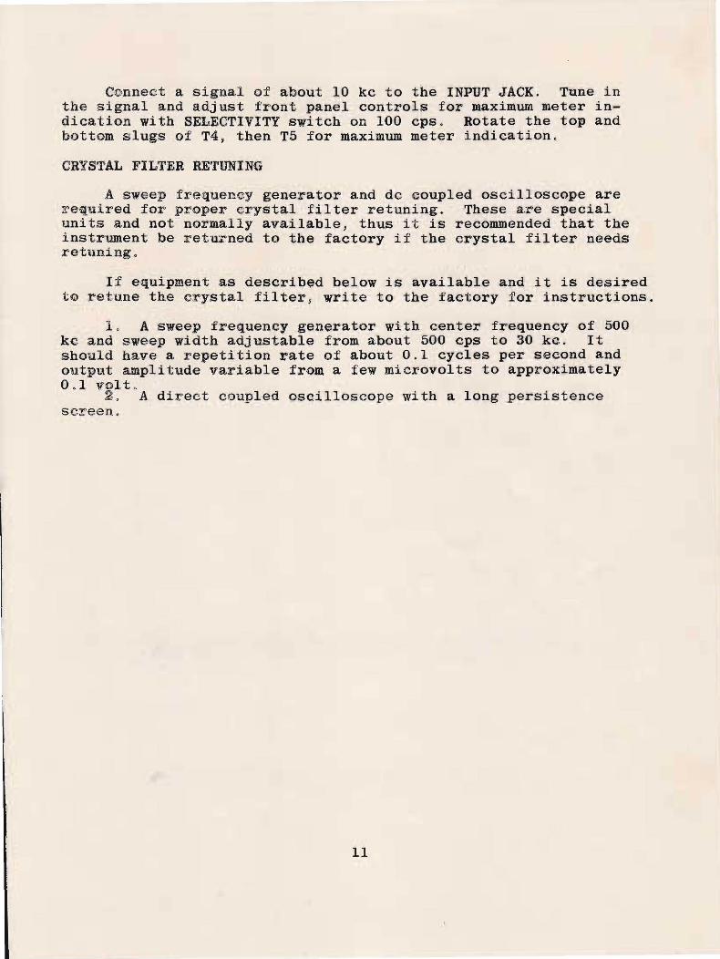
Connect a signal of about 10 kc to the INPUT JACK. Tune inthe signal and a,dj ust front panel controls for maximum meter indication with SELECTIVITY switch on 100 cps. Rotate the top andbottom slugs of T4, then T5 for maximum meter indication,
CRYSTAL FILTER RETUNING
A sweep frequency generator and dc coupled oscilloscope areJrequired for proper crystal filter retuning. These are specialunits and not normally available, thus it is recommended that theinstrument be retu~ned to the factory if the crystal filter needsretuning.
If eq'!.:Upment as described below is available and it is desiredtm retune the crystal filter, write to the factory for instructions.
1, A sweep frequency generator with center frequency of 500kc and sweep width adjustable from about 500 cps to 30 kc. Itshould have a repetition ~ate of about 0.1 cycles per second andoutput amplitude variable from a few microvolts to approximately0,1 volt.
2. A direct coupled oscilloscope with a long persistencescreen,
11

LIST OF MANUFACTDRERS
Symbol is 1 isted in P8>~t'tS list under manufacturer.
SymbolABCDEFGH1JKLMNopQRSTURY
Aerovox Co:rpo:r-a.tj.onAlden Products CompanyAllen-ES}:"adley Cc)mpany
Pace ElectI"i~jal Instrument CoBussman Mig CompanyCentralab (Div of Globe-Union Inc)Cleveland Electronics InaThe Daven CompanyE:rie Resi,stoJr Corp'.YirationInternational Resistor CompanyJohnson Electr'oniesE ,F. J'ohnso!l CoJames Millen Mfg Co IncOak Mfg CompanyRadio ReceptoI" Co IncSangamo Elef.rtric CompanySher~ld CTystal CDrporationSwitch.G:f'aft !ncSylvania Electric Products IncTransf~rmer Technicians IncRAILWAY COMMUNICATIONS INC
List of abbreviations in parts list.
AARDCSSDWWSM'pOT
Linear taperSelected as requiredDep~sited carbonShaft ~meas from end of bushing)Screwdriver shaftWire woundSilv·el" micaPoten t, i o:mer.e:;,·

on C16,25)
_LZ #IF- ¢e:JC> OiI,;,'pc. A1ii /'Yilt tZ5.J1.1 MF 200 WVDC metalizedor .1 MF 200 WVDC paper3.3 MMF NPO1.5-7 MMF trimmer7-45 MMF trimmer(plus SM cap if required
1. 5 MMF NPO.2.2 lIMY NPO47 MMF 8M±5%.001 MF disc ceramic200 MMF 8M ±5%250 MMF 8M ±5%200 MMF Air type 200 L15160 MMF NPO ceramic ±5%500 MMF ceramic or 8M ±10%.003 disc ceramic360 MMF SM ±5%50 MMF 8M ±5%68 MMF 8M ±5%910 MMF 8M ±5%360 MMF 8M ±5%2-8 MMF air trimmer, 13/16" S (from mtg)3-12 MMF air trimmer 13/16" S (from mtg)356 MMF NPO ceramic ±5%30 MMF 8M
J
A
JJ
MI
14
APC typeAPC type
DescriptionAttenuator.l)/
CAPACITORS (ALL SOO WVDC unless specified)P82 A 1 MF-200V WVDC metalized paperPLT-770 Q 20-20-20 MF, 400-400-2SV dry electrolytic
-1?"'O±OO6'" mmf SM ±S%t.IlEU.. J9).01 MF-disc ceramic
~.ymbo1
01..
ClC3C4CS :~, 35..1:2-50-54,5659,60,66'72 j 73 , 7-=5:.....-_,L6, 7.1-/Z7C6,9,10,55 P8271,74,78C8,12Cll,15,20,24 T82A-l.5C16,25,38 T82A-740,42,44,4846,81,88C17,21C26C29C31,32,62,64 -C33C34C36 167-12C41, 43,45,47,49CS7,58,67C61C63,70C65C68C69C70C80C83C84C87
PARTS LIST------<=P:-a-r-;-t--------~---------~---------------
NoSPECS774
ACACL1L2L3Xl,3X2,4
202 FlAC902 PMTH31332360A2366499.935500.065
B Line cordB Chassis connectorU Choke 7HYRY 30KC osc coilRY 500KC osc coilR CrystalR Crystal
13

PARTS LIST
Output transformerPower transformerVacuum tubeVacuum tubeVacuum tubeVacuum tubesVacuum tubeVacuum tubes
77290-F3 0PM-3A H5822 L
3134 U3135 UOB2.~ 1;(P~YbAt6AQ5,6BH66BJ6l2AU7
PartSymbol No M DescriptionXrS--',7-------c4n9~9~·- .--,l...."O""O,..-------....=R--.;C-rys ta IX6,8 500.900 R CrystalX9 498.530 R CrystalXIO 501.470 R Crystal
10035 N Dial, ratio 12/1IN34A T Diodes, germanium3002 RY 450KC LP filter, & input transformerHKP F Fuse holder with I amp fusellL S Jackl2A S Jack42-W E 0-200 DC uA special scale, 800~
5Ml P Rectifiers, selenium 100 ma77287-Fl 0 Switch, rotary 2 pole 4 position77288-F3 0 Switch, rotary, 2 deck, 1 pole 3
positions88408-F2 0 Switch, rotary, 2 deck, 1 pole 7
positionsSwitch, rotary, 3 pole 3 positions3" speaker500 KC IF transformer
S3
Tl,2,3,45,6T8T9VII .V2 1J,Ji/;fJliJ
Vl<}cVl,<i,6,8V5V3,7,9
84,5
JlJ2,3METERSR1,2,3,4Sl52
Dl,2,3,4LPF
RESISTORS680~ 2W5K lOWlOOK 1/2W
5K l/2W500~ pot A2500~ pot A2700~ 1/2W220K 1/2W
RlR4R5,6,32,4143,45,51R1,8,34,36R17.; qR18,53,62R19 J 63R20,39,44,56,64R21,35,3849,65,68R22,23,29R24R25,37R30R3l
CC
220~
820J\.120K47K2K6.8K
1/2W1/2W1/2W1/2W1/2W1/2W
10%10% WW10%
10%10%10%10%5%10%
1%3/4" S3/8" S, SD10%10%
14

Paz'tSymbol NoR40,50,52R42 Qll-130AC OFF 76-1R46R47, ~48R54R55,58R57R59R60R61R6G
PARTS LIST.~~-----'----------'-
M Descript=i_o_n----=---=- ~__27K 1/2 10%
K 250K POT A 3/8" SSPST sw for R42850.1'- 5W 10%13K 1/2W 5%1M 1/2W 10%
C 5K POT A 3/8" S, SD7K 1/2W 1% DC490.1'- 1/2W 1% DC100~ 1/2W 1% DC820.1'- 1/2W 10%62K 1/2W 10%
15

I.F. STAGEr- -------..
METER
HEADSETJACKt SPEAKER
~[tJ
Ii
METERRECTIFI ER
l
AUDIOINPUTJACK
DEMOO
METERCCTAMP
MONITOR
U5Ek§~AMLSB
MON.OS
501.47KC 498.53KC
•
500 KCISOLATION
ANP.
/ ------..BANDWIDTH 100CPS I
\1J[ 3KC
10K" I MOD IUBAL ~
UNBAL1-
-t}500 TO,oOKC
ISOLATIONATTEN. AMP.
¢50/60CPS.
115 V.A.C.
REGULATED
POWER SUPPLY
UNREGULATED I ~
INPUT CIRCUIT/ ,
METERSW. " /METFR CI RCUIT