Embed Size (px)
Citation preview
CM2N3835en_04 2016-05-19
Building Technologies
s 3835
Desigo TRA
PL-Link I/O Block RXM21.1 Use with PXC3 series room automation station
• The PL-Link I/O block contains the inputs and outputs controlled by a room automation station via KNX PL-Link.
• KNX PL-Link communications • Valve control (3 potential-free relay contacts) • Thermal valve actuator control (AC 24 V) • Motor-driven valve and damper actuators
(AC 24 V, 2- or 3-point) • Temperature input LG-Ni 1000 • 2 digital inputs • Operating voltage AC 230 V • Pluggable screw terminals
Use
The RXM21.1 PL-Link I/O Block allows control of a single fancoil unit by a PXC3 room automation station via the KNX PL-Link peripheral bus. It is optimized for fancoil installation and control in terms of housing, connection terminals and I/O mix.
The KNX PL-Link (PeripheraL-Link) is a two-wire bus system optimized for communication between peripheral devices (sensors, actors) and the modular PXC3 room automation stations in the domains or HVAC, lighting and shading.
2 / 14
Siemens RXM21.1 - PL-Link I/O Block CM2N3835en_04 Building Technologies 2016-05-19
Functions
The application on the room automation station determines the device functionality.
Type overview and ordering
The device is supplied without terminal covers. Terminal covers (RXZ20.1) can be ordered optionally.
Equipment combinations
• The RXM21.1 PL-Link I/O Block only works together with PXC3 series room automation stations.
• LG-Ni 1000 temperature sensors can be connected. • AC 24 V actors from Siemens or third party can be connected. • Signaling inputs relay outputs etc. see pages 10, 11.
Technical design
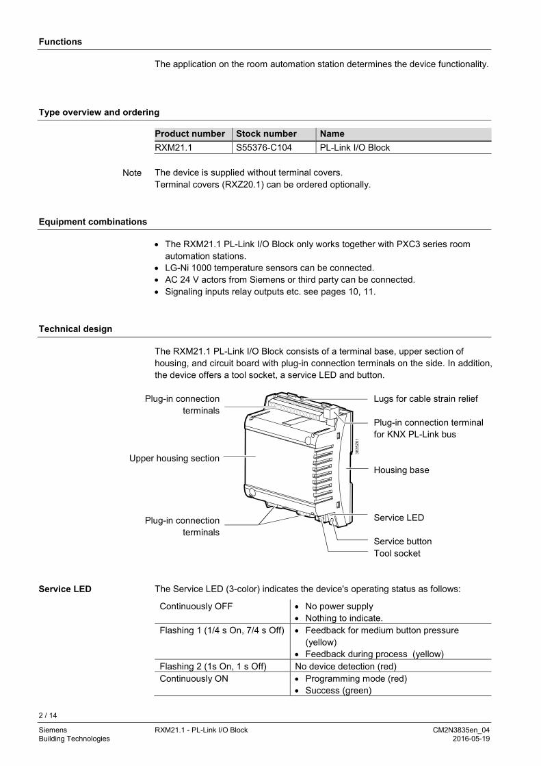
The RXM21.1 PL-Link I/O Block consists of a terminal base, upper section of housing, and circuit board with plug-in connection terminals on the side. In addition, the device offers a tool socket, a service LED and button.
Plug-in connection terminals
Upper housing section
Plug-in connection terminals
3835
Z01
Lugs for cable strain relief Plug-in connection terminal for KNX PL-Link bus Housing base Service LED Service button Tool socket
The Service LED (3-color) indicates the device's operating status as follows:
Continuously OFF • No power supply • Nothing to indicate.
Flashing 1 (1/4 s On, 7/4 s Off) • Feedback for medium button pressure (yellow)
• Feedback during process (yellow) Flashing 2 (1s On, 1 s Off) No device detection (red) Continuously ON • Programming mode (red)
• Success (green)
Product number Stock number Name RXM21.1 S55376-C104 PL-Link I/O Block
Note
Service LED
3 / 14
Siemens RXM21.1 - PL-Link I/O Block CM2N3835en_04 Building Technologies 2016-05-19
The device carries out the following commands from the service button:
Button pressure Action Short (< 0.5 s) • Switch on/off programming mode
• Do not indicate connection test result (0.5...2.s) • No action Medium (2...20 s)
• Start connection test
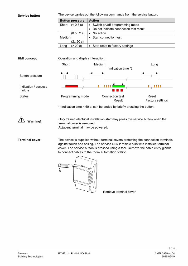
Long (> 20 s) • Start reset to factory settings Operation and display interaction:
Short Medium Long Indication time *)
Button pressure Indication / success Failure
Status Programming mode Connection test Reset Result Factory settings
*) Indication time = 60 s; can be ended by briefly pressing the button.
Warning!
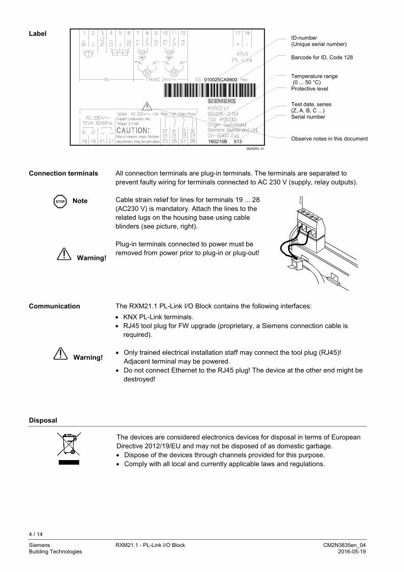
Only trained electrical installation staff may press the service button when the terminal cover is removed! Adjacent terminal may be powered. The device is supplied without terminal covers protecting the connection terminals against touch and soiling. The service LED is visible also with installed terminal cover. The service button is pressed using a tool. Remove the cable entry glands to connect cables to the room automation station.
3873
J02
Remove terminal cover
Service button
HMI concept
Terminal cover
4 / 14
Siemens RXM21.1 - PL-Link I/O Block CM2N3835en_04 Building Technologies 2016-05-19
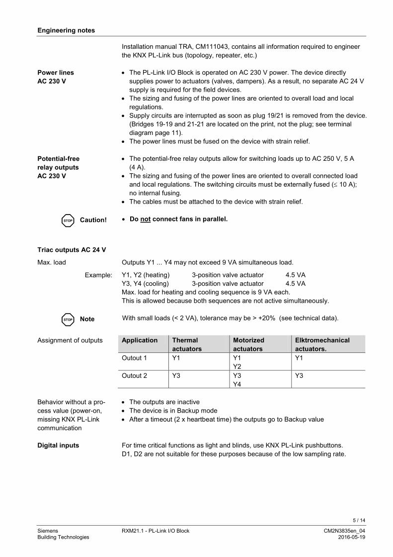
ID-number (Unique serial number) Barcode for ID, Code 128 Temperature range (0 ... 50 °C) Protective level Test date, series (Z, A, B, C ...) Serial number
Observe notes in this document
All connection terminals are plug-in terminals. The terminals are separated to prevent faulty wiring for terminals connected to AC 230 V (supply, relay outputs).
STOP Note
Warning!
Cable strain relief for lines for terminals 19 ... 28 (AC230 V) is mandatory. Attach the lines to the related lugs on the housing base using cable blinders (see picture, right). Plug-in terminals connected to power must be removed from power prior to plug-in or plug-out!
3873
J04
The RXM21.1 PL-Link I/O Block contains the following interfaces: • KNX PL-Link terminals. • RJ45 tool plug for FW upgrade (proprietary, a Siemens connection cable is
required).
Warning! • Only trained electrical installation staff may connect the tool plug (RJ45)!
Adjacent terminal may be powered. • Do not connect Ethernet to the RJ45 plug! The device at the other end might be
destroyed!
Disposal
The devices are considered electronics devices for disposal in terms of European Directive 2012/19/EU and may not be disposed of as domestic garbage. • Dispose of the devices through channels provided for this purpose. • Comply with all local and currently applicable laws and regulations.
Label
Connection terminals
Communication
5 / 14
Siemens RXM21.1 - PL-Link I/O Block CM2N3835en_04 Building Technologies 2016-05-19
Engineering notes
Installation manual TRA, CM111043, contains all information required to engineer the KNX PL-Link bus (topology, repeater, etc.) • The PL-Link I/O Block is operated on AC 230 V power. The device directly
supplies power to actuators (valves, dampers). As a result, no separate AC 24 V supply is required for the field devices.
• The sizing and fusing of the power lines are oriented to overall load and local regulations.
• Supply circuits are interrupted as soon as plug 19/21 is removed from the device. (Bridges 19-19 and 21-21 are located on the print, not the plug; see terminal diagram page 11).
• The power lines must be fused on the device with strain relief. • The potential-free relay outputs allow for switching loads up to AC 250 V, 5 A
(4 A). • The sizing and fusing of the power lines are oriented to overall connected load
and local regulations. The switching circuits must be externally fused (≤ 10 A); no internal fusing.
• The cables must be attached to the device with strain relief.
STOP Caution! • Do not connect fans in parallel.
Outputs Y1 ... Y4 may not exceed 9 VA simultaneous load.
Y1, Y2 (heating) 3-position valve actuator 4.5 VA Y3, Y4 (cooling) 3-position valve actuator 4.5 VA Max. load for heating and cooling sequence is 9 VA each. This is allowed because both sequences are not active simultaneously.
STOP Note With small loads (< 2 VA), tolerance may be > +20% (see technical data).
Application Thermal
actuators Motorized actuators
Elktromechanical actuators.
Outout 1 Y1 Y1 Y2
Y1
Outout 2 Y3 Y3 Y4
Y3
• The outputs are inactive • The device is in Backup mode • After a timeout (2 x heartbeat time) the outputs go to Backup value For time critical functions as light and blinds, use KNX PL-Link pushbuttons. D1, D2 are not suitable for these purposes because of the low sampling rate.
Power lines AC 230 V
Potential-free relay outputs AC 230 V
Triac outputs AC 24 V
Max. load
Example:
Assignment of outputs
Behavior without a pro-cess value (power-on, missing KNX PL-Link communication
Digital inputs
6 / 14
Siemens RXM21.1 - PL-Link I/O Block CM2N3835en_04 Building Technologies 2016-05-19
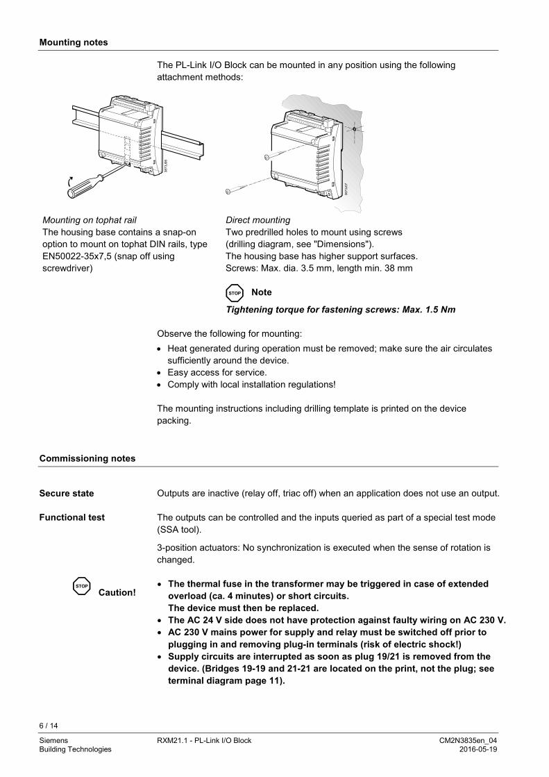
Mounting notes
The PL-Link I/O Block can be mounted in any position using the following attachment methods:
3873
J06
3873
J07
Mounting on tophat rail The housing base contains a snap-on option to mount on tophat DIN rails, type EN50022-35x7,5 (snap off using screwdriver)
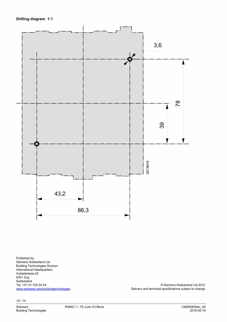
Direct mounting Two predrilled holes to mount using screws (drilling diagram, see "Dimensions"). The housing base has higher support surfaces. Screws: Max. dia. 3.5 mm, length min. 38 mm
STOP Note
Tightening torque for fastening screws: Max. 1.5 Nm Observe the following for mounting: • Heat generated during operation must be removed; make sure the air circulates
sufficiently around the device. • Easy access for service. • Comply with local installation regulations! The mounting instructions including drilling template is printed on the device packing.
Commissioning notes
Outputs are inactive (relay off, triac off) when an application does not use an output. The outputs can be controlled and the inputs queried as part of a special test mode (SSA tool).
3-position actuators: No synchronization is executed when the sense of rotation is changed.
STOP
Caution!
• The thermal fuse in the transformer may be triggered in case of extended overload (ca. 4 minutes) or short circuits. The device must then be replaced.
• The AC 24 V side does not have protection against faulty wiring on AC 230 V. • AC 230 V mains power for supply and relay must be switched off prior to
plugging in and removing plug-in terminals (risk of electric shock!) • Supply circuits are interrupted as soon as plug 19/21 is removed from the
device. (Bridges 19-19 and 21-21 are located on the print, not the plug; see terminal diagram page 11).
Secure state
Functional test
7 / 14
Siemens RXM21.1 - PL-Link I/O Block CM2N3835en_04 Building Technologies 2016-05-19
Operating notes
• When power is off, all outputs are inactive • When KNX PL-Link communications fails, all outputs go to the configured
backup values (after 2 x Heartbeat time).
Technical data
Power Rated voltage AC 230 V Frequency 50 / 60 Hz Power consumption incl. connected field
devices Max. 12 VA
Internal fuse Thermal, irreversible External supply line protection (EU) Slow-blow fuse max. 10 A
or Circuit breaker max. 13 A Characteristic B, C, D according to EN 60898
Protection Protection against faulty wiring on AC 230 V No protection for On / outputs
Inputs Status inputs (D1, D2) Quantity 2 (for potential-free contacts) Contact voltage. DC 16 V Contact current DC 5 mA Contact transfer resistance Max. 100 Ohm Contact insulation resistance Min. 50 kOhm Switching time: Min. 20 ms “ON”, min. 20 ms “OFF” Heartbeat 1 s For time critical functions as light and blinds, use KNX PL-Link pushbuttons.
D1, D2 are not suitable for these purposes because of the low sampling rate. Protection against faulty wiring on AC 24 V Protected Measured value input B1 Connectable temperature sensor LG-Ni 1000 Quantity 1 Measuring range 0...50 °C Sensor current 0.5 mA Resolution 0. 1 K Measuring error at 25 °C sensor temp.
(without line resistance) Max. 0.5 K
Heartbeat 10 s Protection against faulty wiring on AC 24 V Protected Outputs Triac outputs AC 24 V Quantity 4 (Y1 ... Y4) Output voltage AC 24 V +/- 20%
(at <2 VA load: possibly >+20%!) Outputs Y1...Y4 are on AC 24 V, the triac closes against contact to V~/ G Output current Max. 0.5 A Total rated load
(at simultaneous load on 2 outputs) Max. 9 VA
Protection against overload No internal limitation
8 / 14
Siemens RXM21.1 - PL-Link I/O Block CM2N3835en_04 Building Technologies 2016-05-19
Relay outputs Quantity 3 (Q14, Q24, Q34) Relay type Monostable, NO contact Contact rating at alternating current Switching voltage Max. AC 250 V, min. AC 19 V Rated current resistive / inductive Max. AC 5 A / 4 A (cosϕ = 0.6) Switch-on current (200 ms half-time) Max. 20 A Switching current at AC 19 V Min. AC 10 mA Contact rating at direct current Switching voltage Max. DC 250 V, min. DC 5 V Switching current at DC 5 V Min. DC 100 mA Switching output Max. 20 W Inductive load L/R Max. 7 ms Locking (in firmware) • Only 1 relay active at a time
• All relays 1 s OFF upon change of stage
Caution External supply line protection See section power supply KNX PL-Link bus Interface type Galvanically isolated Transceiver TP-UART Bus power 5 mA Baud rate 9.6 kbps Protection against faulty wiring AC 24 V Proteced Bus topology: See installation guide TRA, CM111043 Line connections Connection terminals for signals and power
supply (plug-in screw terminals) Solid or stranded 0,25 ... 2.5 mm2 or 2 x 1.5 mm2
Connection terminals for KNX PL-Link bus (plug-in screw terminals)
Solid or stranded wire 2 x max 1.0 mm2 e.g. YCYM 2x2x0.8
Cable length See TRA installation manual, CM111043
Tool connection cable Max. 3 m Protection data Housing protection to EN 60529 IP30 with terminal cover and wall
mounting without tophat rail IP20 for all other mounting types Protection class Suited for use in Protection class I – or Protection class II - Plants Ambient conditions Operation Class 3K5 as per IEC 60721-3-3 Temperature 0 ... 50 °C Humidity < 85% r.h. Transport Class 2K3 as per IEC 60721-3-2 Temperature – 25 ... 70 °C Humidity < 95% r.h.
9 / 14
Siemens RXM21.1 - PL-Link I/O Block CM2N3835en_04 Building Technologies 2016-05-19
Standards, directives and approvals
Product standard EN 60730-1 Automatic electrical controls for household and similar use
Electromagnetic compatibility (Applications) For use in residential, commercial and industrial environments
EU conformity (CE) See CM2T3877xx *) UL certification (US) UL 916 RCM conformity (EMC) CA2T3834en_C1 *) EAC conformity Eurasia conformity Environmental compatibility Product environmental declaration
(contains data on RoHS compliance, materials composition, packaging, environmental benefit, disposal)
CA2E3871 *)
Dimensions Refer to “Dimensions” Weight Without/with packaging 0.640 kg / 0.675 kg
*) The documents can be downloaded from http://siemens.com/bt/download.
10 / 14
Siemens RXM21.1 - PL-Link I/O Block CM2N3835en_04 Building Technologies 2016-05-19
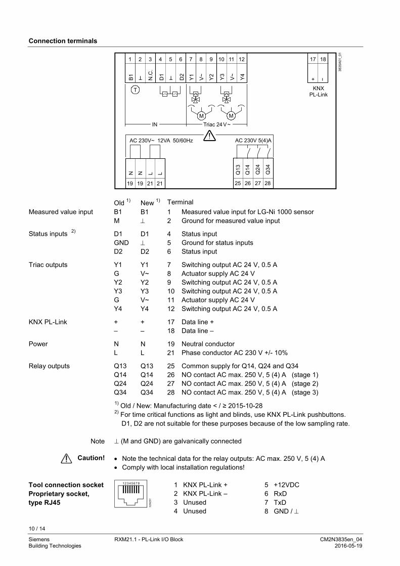
Connection terminals
1 2 3 4 5 6 7 8 9 10 11 12 17 18
KNXPL-Link
25 26 27 2819 19 21 21
Old 1) New 1) Terminal Measured value input B1 B1 1 Measured value input for LG-Ni 1000 sensor M ⊥ 2 Ground for measured value input
Status inputs 2) D1 D1 4 Status input GND ⊥ 5 Ground for status inputs D2 D2 6 Status input
Triac outputs Y1 Y1 7 Switching output AC 24 V, 0.5 A G V~ 8 Actuator supply AC 24 V Y2 Y2 9 Switching output AC 24 V, 0.5 A Y3 Y3 10 Switching output AC 24 V, 0.5 A G V~ 11 Actuator supply AC 24 V Y4 Y4 12 Switching output AC 24 V, 0.5 A
KNX PL-Link + + 17 Data line + – – 18 Data line –
Power N N 19 Neutral conductor L L 21 Phase conductor AC 230 V +/- 10%
Relay outputs Q13 Q13 25 Common supply for Q14, Q24 and Q34 Q14 Q14 26 NO contact AC max. 250 V, 5 (4) A (stage 1) Q24 Q24 27 NO contact AC max. 250 V, 5 (4) A (stage 2) Q34 Q34 28 NO contact AC max. 250 V, 5 (4) A (stage 3)
1) Old / New: Manufacturing date < / ≥ 2015-10-28 2) For time critical functions as light and blinds, use KNX PL-Link pushbuttons.
D1, D2 are not suitable for these purposes because of the low sampling rate. ⊥ (M and GND) are galvanically connected • Note the technical data for the relay outputs: AC max. 250 V, 5 (4) A • Comply with local installation regulations!
1
3206
Z01
2 3 4 5 6 7 8
1 KNX PL-Link + 2 KNX PL-Link – 3 Unused 4 Unused
5 +12VDC 6 RxD 7 TxD 8 GND / ⊥
Note
Caution!
Tool connection socket Proprietary socket, type RJ45
11 / 14
Siemens RXM21.1 - PL-Link I/O Block CM2N3835en_04 Building Technologies 2016-05-19
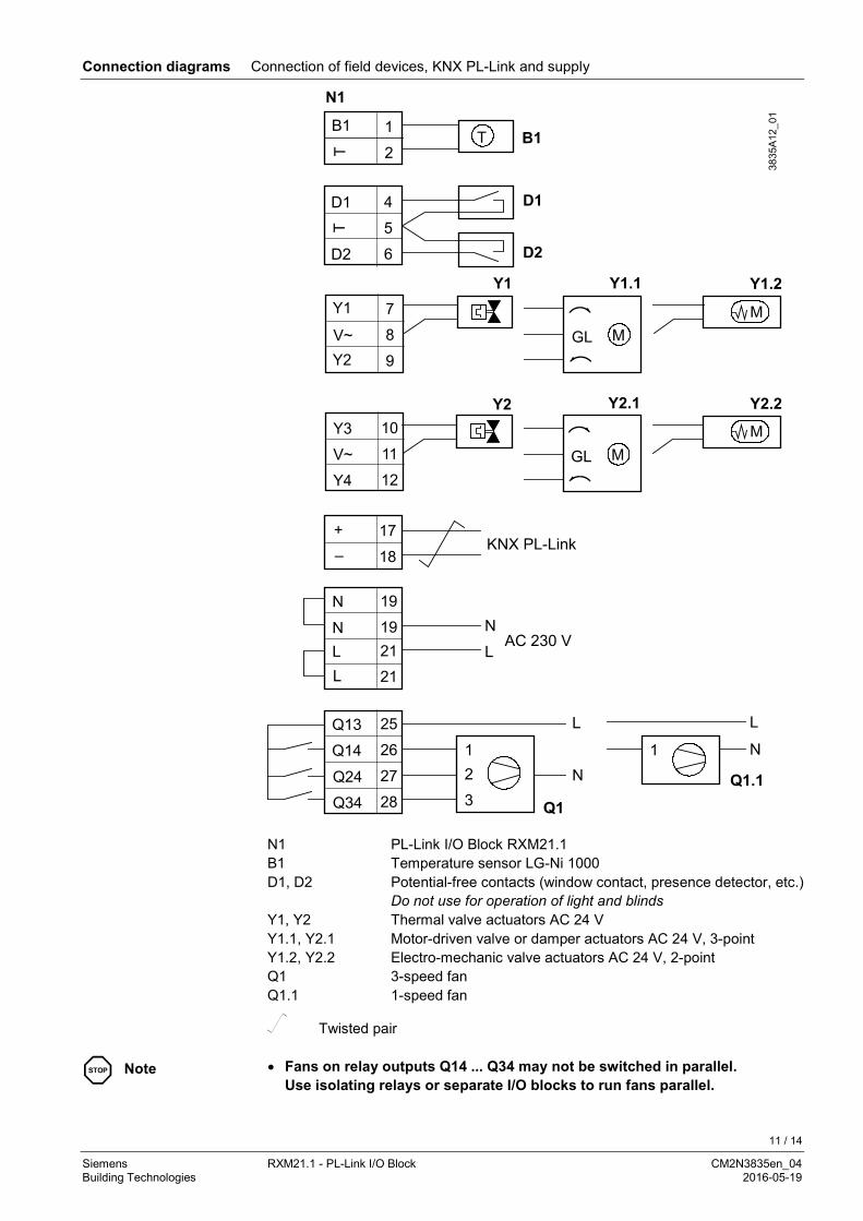
Connection diagrams Connection of field devices, KNX PL-Link and supply
+
M
M
N1 PL-Link I/O Block RXM21.1 B1 Temperature sensor LG-Ni 1000 D1, D2 Potential-free contacts (window contact, presence detector, etc.) Do not use for operation of light and blinds Y1, Y2 Thermal valve actuators AC 24 V Y1.1, Y2.1 Motor-driven valve or damper actuators AC 24 V, 3-point Y1.2, Y2.2 Electro-mechanic valve actuators AC 24 V, 2-point Q1 3-speed fan Q1.1 1-speed fan
Twisted pair
STOP Note • Fans on relay outputs Q14 ... Q34 may not be switched in parallel. Use isolating relays or separate I/O blocks to run fans parallel.
12 / 14
Siemens RXM21.1 - PL-Link I/O Block CM2N3835en_04 Building Technologies 2016-05-19
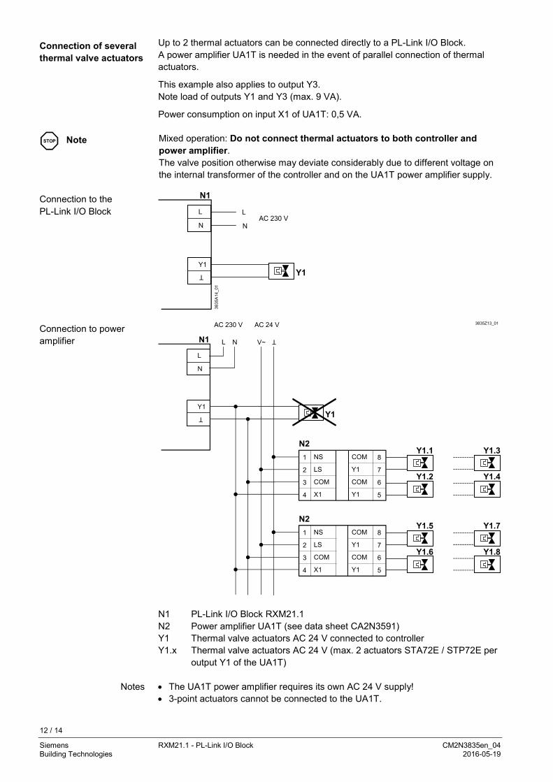
Up to 2 thermal actuators can be connected directly to a PL-Link I/O Block. A power amplifier UA1T is needed in the event of parallel connection of thermal actuators.
This example also applies to output Y3. Note load of outputs Y1 and Y3 (max. 9 VA).
Power consumption on input X1 of UA1T: 0,5 VA.
STOP Note Mixed operation: Do not connect thermal actuators to both controller and power amplifier. The valve position otherwise may deviate considerably due to different voltage on the internal transformer of the controller and on the UA1T power amplifier supply.
1
2
3
4
COM
8
7
6
5
COM
COM
1
2
3
4
COM
8
7
6
5
COM
COM
N1 PL-Link I/O Block RXM21.1 N2 Power amplifier UA1T (see data sheet CA2N3591) Y1 Thermal valve actuators AC 24 V connected to controller Y1.x Thermal valve actuators AC 24 V (max. 2 actuators STA72E / STP72E per
output Y1 of the UA1T) • The UA1T power amplifier requires its own AC 24 V supply! • 3-point actuators cannot be connected to the UA1T.
Connection of several thermal valve actuators
Connection to the PL-Link I/O Block
Connection to power amplifier
Notes
13 / 14
Siemens RXM21.1 - PL-Link I/O Block CM2N3835en_04 Building Technologies 2016-05-19
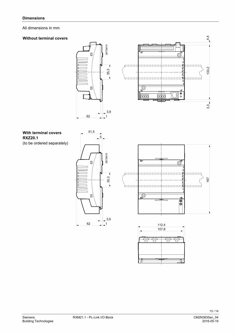
Dimensions
Without terminal covers
62 13,9
35,3
133,
2
3873
M14
3,3
4,4
With terminal covers RXZ20.1 (to be ordered separately)
62 13,9
35,3
167
112,4107,8
51,5
5
3873
M15
All dimensions in mm
14 / 14
Siemens RXM21.1 - PL-Link I/O Block CM2N3835en_04 Building Technologies 2016-05-19
86,3
43,2
78
39
3873
M16
3,6
Published by: Siemens Switzerland Ltd. Building Technologies Division International Headquarters Gubelstrasse 22 6301 Zug Switzerland Tel. +41 41-724 24 24 www.siemens.com/buildingtechnologies
© Siemens Switzerland Ltd 2012 Delivery and technical specifications subject to change
Drilling diagram 1:1