Embed Size (px)
Citation preview

APPLICATION NOTE
R01AN1923EJ0100 Rev. 1.00 Page 1 of 31 Sep. 1, 2014
RX21A Group Using the Temperature Sensor to Calculate the Ambient Temperature
Abstract This document describes a method of using the RX21A Group temperature sensor to calculate the ambient temperature.
Products RX21A Group, 64-Pin Package, ROM Capacity: 256 Kbytes to 512 Kbytes
RX21A Group, 80-Pin Package, ROM Capacity: 256 Kbytes to 512 Kbytes
RX21A Group, 100-Pin Package, ROM Capacity: 256 Kbytes to 512 Kbytes
Note: Only the G version (operating temperature: –40°C to +105°C) of the products are the target products.
R01AN1923EJ0100 Rev. 1.00
Sep. 1, 2014

RX21A Group Using the Temperature Sensor to Calculate the Ambient Temperature
R01AN1923EJ0100 Rev. 1.00 Page 2 of 31 Sep. 1, 2014
Contents
1. Specifications ..................................................................................................................................... 3
2. Operation Confirmation Conditions .................................................................................................... 5
3. Reference Application Notes .............................................................................................................. 5
4. Hardware ............................................................................................................................................ 6 4.1 Hardware Configuration ............................................................................................................... 6 4.2 Pins Used ..................................................................................................................................... 6
5. Software ............................................................................................................................................. 7 5.1 Operation Overview ..................................................................................................................... 7
5.1.1 Formula for the Temperature Characteristic......................................................................... 9 5.2 File Composition ........................................................................................................................ 11 5.3 Option-Setting Memory .............................................................................................................. 12 5.4 Constants ................................................................................................................................... 12 5.5 Variables .................................................................................................................................... 15 5.6 Functions .................................................................................................................................... 16 5.7 Function Specifications .............................................................................................................. 17 5.8 Flowcharts .................................................................................................................................. 21
5.8.1 Main Processing ................................................................................................................. 21 5.8.2 Port Initialization ................................................................................................................. 22 5.8.3 Peripheral Function Initialization ......................................................................................... 22 5.8.4 CMT Initialization ................................................................................................................ 23 5.8.5 IRQ Initialization .................................................................................................................. 24 5.8.6 Processing to Update the 7SEG Display Data ................................................................... 25 5.8.7 Processing to Switch the 7SEG Select Output ................................................................... 25 5.8.8 Processing to Display a Dash on the 7SEG ....................................................................... 26 5.8.9 Compare Match Interrupt Handling .................................................................................... 26 5.8.10 AD and Temperature Sensor Initialization ......................................................................... 27 5.8.11 Obtain the A/D Conversion Status .................................................................................... 28 5.8.12 Obtain the Temperature Sensor Measurement Result ..................................................... 28 5.8.13 Obtain the Current Temperature ....................................................................................... 28 5.8.14 Processing for Temperature Sensor Calibration ............................................................... 29 5.8.15 Processing for Temperature Sensor Measurement .......................................................... 29 5.8.16 Processing to Calculate the Current Temperature ............................................................ 29 5.8.17 A/D Conversion Complete Interrupt Handling ................................................................... 30
6. Sample Code .................................................................................................................................... 31
7. Reference Documents ...................................................................................................................... 31

RX21A Group Using the Temperature Sensor to Calculate the Ambient Temperature
R01AN1923EJ0100 Rev. 1.00 Page 3 of 31 Sep. 1, 2014
1. Specifications This document describes using the temperature sensor to measure the ambient temperature of the MCU. The ambient temperature is measured and the result is displayed on a 7-segment LED (hereinafter referred to as 7SEG).
In order to measure the ambient temperature of the MCU, the temperature sensor is calibrated beforehand. The calibration performed in this application note calculates the temperature slope necessary for the formula for the temperature characteristic.
In the G version of the RX21A Group MCU, the calibration data for the temperature sensor that is measured for every chip is stored when shipped. The temperature slope can be calculated using the data stored on the chip and a temperature obtained by the user in the trial measurement.
In the accompanying sample code, an ambient temperature of 25°C (hereinafter referred to as normal reference temperature) is assumed as the temperature obtained in the user trial measurement and used to calculate the ambient temperature. Refer to section 5.1.1 for details on calibration.
Table 1.1 lists the Peripheral Functions and Their Applications. Table 1.1 Peripheral Functions and Their Applications
Peripheral Function Application 10-bit A/D converter (hereinafter referred to as AD) The AD measures temperature sensor output.
Temperature sensor The temperature sensor measures the ambient temperature of the MCU. Compare match timer (CMT0) (hereinafter referred to as CMT) The CMT is used as a timer for the temperature measurement cycle.
External pin interrupt (IRQ2) (hereinafter referred to as IRQ) Switch input for calibrating with the normal reference temperature.
I/O ports I/O ports are used to display the result of the temperature measurement on the 7SEG.

RX21A Group Using the Temperature Sensor to Calculate the Ambient Temperature
R01AN1923EJ0100 Rev. 1.00 Page 4 of 31 Sep. 1, 2014
Figure 1.1 shows the Transitioning States and Patterns Displayed on the 7SEG.
Status 7SEG display
Release from the reset state
All segments are off
Dash displayed
Temperature measurement result displayed as a decimal number
Display when the temperature measurement result is less than 0°C
Reset state
Waiting for calibration to start
Displayed temperature isupdated in 600 ms cycles
Switch is pushed
to
Display when the temperature measurement result is 100°C or higher
Figure 1.1 Transitioning States and Patterns Displayed on the 7SEG

RX21A Group Using the Temperature Sensor to Calculate the Ambient Temperature
R01AN1923EJ0100 Rev. 1.00 Page 5 of 31 Sep. 1, 2014
2. Operation Confirmation Conditions The sample code accompanying this application note has been run and confirmed under the conditions below. Table 2.1 Operation Confirmation Conditions
Item Contents MCU used R5F521A8BDFP (RX21A Group)
Operating frequencies
Main clock: 20 MHz System clock (ICLK): 20 MHz Peripheral module clock B (PCLKB): 20 MHz Peripheral module clock D (PCLKD): 2.5 MHz
Operating voltage 3.3 V Integrated development environment
Renesas Electronics Corporation High-performance Embedded Workshop Version 4.09.01
C compiler
Renesas Electronics Corporation C/C++ Compiler Package for RX Family V.1.02 Release 01 Compile options –cpu=rx200 –output=obj="$(CONFIGDIR)\$(FILELEAF).obj" –debug –nologo The integrated development environment default settings are used.
iodefine.h version Version 1.1 Endian Little endian Operating mode Single-chip mode Processor mode Supervisor mode Sample code version Version 1.00
3. Reference Application Notes For additional information associated with this document, refer to the following application notes.
• RX21A Group Initial Setting Rev. 1.00 (R01AN1486EJ) • RX Family Coding Example of Wait Processing by Software Rev. 1.00 (R01AN1852EJ)
The initial setting functions and wait processing by software in the reference application notes are used in the sample code in this application note. The revision numbers of the reference application notes are current as of the issue date of this application note. However, the latest versions are always recommended. Visit the Renesas Electronics Corporation website to check and download the latest versions.

RX21A Group Using the Temperature Sensor to Calculate the Ambient Temperature
R01AN1923EJ0100 Rev. 1.00 Page 6 of 31 Sep. 1, 2014
4. Hardware
4.1 Hardware Configuration Figure 4.1 shows the Connection Example.
RX21A Group
VCC
P32/IRQ2 P20 to P26
Switch input
PA0
7
VCC
Note 1. This example assumes 7SEG dynamic common anodes are used.
VCC
PA1 7SEG *1 7SEG *1
ab
cd
e
f ga
b
cd
e
f g
Figure 4.1 Connection Example
4.2 Pins Used Table 4.1 lists the Pins Used and Their Functions. The pins used assume that the target product is a 100-pin MCU. When using products with less than 100 pins, select pins appropriate to the product used. Table 4.1 Pins Used and Their Functions
Pin Name I/O Function P32/IRQ2 Input Switch input for executing calibration
P20 Output Outputs segment a of the 7SEG P21 Output Outputs segment b of the 7SEG P22 Output Outputs segment c of the 7SEG P23 Output Outputs segment d of the 7SEG P24 Output Outputs segment e of the 7SEG P25 Output Outputs segment f of the 7SEG P26 Output Outputs segment g of the 7SEG PA0 Output Outputs the first digit of the 7SEG PA1 Output Outputs the second digit of the 7SEG

RX21A Group Using the Temperature Sensor to Calculate the Ambient Temperature
R01AN1923EJ0100 Rev. 1.00 Page 7 of 31 Sep. 1, 2014
5. Software
5.1 Operation Overview After the MCU is released from the reset state, the I/O ports and peripheral functions are initialized, and the MCU enters the waiting for calibration state. If the IRQ2 interrupt request is generated in this state, calibration is performed. The normal reference temperature is A/D converted in the calibration. The A/D converted value and the temperature sensor calibration data are used to calculate the temperature slope.
When calibration is complete, A/D conversion continues. The A/D converted value and temperate slope are used to calculate the ambient temperature, and the calculated value is displayed on the 7SEG.
In this application note, A/D conversion is performed every 100 ms. Also, in order to calculate the average A/D converted value, six A/D converted values are stored to the RAM, the highest and lowest values are eliminated, and the average of the remaining four values is calculated as the ambient temperature.
The CMT CMI0 interrupt is used to start A/D conversion every 100 ms. The CMT is set to generate a compare match interrupt request in 1 ms cycles, and for each compare match interrupt request generated, the A/D converter cycle counter variable (cnt_cycle) is incremented up to 100 ms.
Settings for the CMT, AD, and temperature sensor are listed below.
CMT0
Count clock: PCLKB divided by 8 Compare match interrupt cycle: 1 ms
AD
Operating mode: Single scan mode A/D conversion start condition: Synchronous trigger (trigger from the temperature sensor) Number of sampling states: 180 states (sampling time is 72 µs) Analog input disconnection detection assist: Not used A/D-converted value addition mode: Not used Self-diagnosis of 10-bit A/D converter: Not used
Temperature sensor
PGA gain *1: 2.7 V ≤ AVCC0 ≤ 3.6 V *2
Note 1. PGA: Programmable gain amplifier
Note 2. Change the constant settings as needed for the user system.

RX21A Group Using the Temperature Sensor to Calculate the Ambient Temperature
R01AN1923EJ0100 Rev. 1.00 Page 8 of 31 Sep. 1, 2014
Figure 5.1 shows the Temperature Measurement Timing Diagram.
Status
Reset pin
Switch input (IRQ2)
(2) (3) (5)(1)
Dash displayedLEDs off7SEG output
(8)
100 ms: Cycle for starting A/D conversion
Compare match interrupt
600 ms: Cycles for temperature calculation processing
(4)
Temperature measurement status *1
(6) (8)
0 1 2 1 2
Note 1. Temperature measurement status:0: Not measured1: Waiting for measurement to be completed2: Measurement completed
(7) (7)
1 2
1 ms: Cycle for generating a compare match interrupt request
MCU operating temperature
7SEG output (temperature displayed)
25°C
50°C
75°C
ResetWaiting for calibration Measuring the temperature
Figure 5.1 Temperature Measurement Timing Diagram
(1) After the MCU is released from the reset state, the AD and temperature sensor are initialized. (2) After the AD is released from the module stop state, the MCU waits 1 µs *1, and then enters the calibration wait
state. At this time, a dash is displayed on the 7SEG. (3) When a falling edge is detected on the switch (IRQ2), the CMT count starts. (4) The CMT is set to generate a compare match interrupt request in 1 ms cycles, and for each compare match interrupt
request generated, the A/D converter cycle counter variable (cnt_cycle) is incremented. (5) When the A/D converter cycle counter variable reaches 100 (100 ms), the TSCR.PGAEN bit is set to 1 (starts
PGA), and A/D conversion starts. (6) A/D conversion is performed six times. Their average becomes the A/D converted value of the normal reference
temperature, the temperature slope is calculated, and calibration is done. (7) When the A/D converter cycle counter variable reaches 100 (100 ms), the TSCR.PGAEN bit is set to 1, and A/D
conversion starts. (8) After performing A/D conversion six times, the current temperature is calculated using the average and the
temperature slope, and then displayed on the 7SEG.
Note 1. After the AD is released from the module stop state, wait at least 1 µs before starting A/D conversion.
RX21A Group Using the Temperature Sensor to Calculate the Ambient Temperature
R01AN1923EJ0100 Rev. 1.00 Page 9 of 31 Sep. 1, 2014
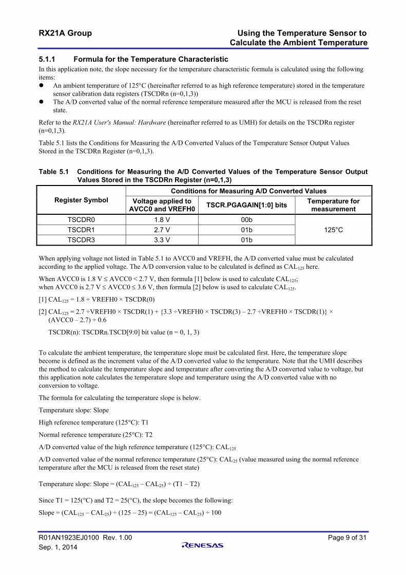
5.1.1 Formula for the Temperature Characteristic In this application note, the slope necessary for the temperature characteristic formula is calculated using the following items: An ambient temperature of 125°C (hereinafter referred to as high reference temperature) stored in the temperature
sensor calibration data registers (TSCDRn (n=0,1,3)) The A/D converted value of the normal reference temperature measured after the MCU is released from the reset
state.
Refer to the RX21A User's Manual: Hardware (hereinafter referred to as UMH) for details on the TSCDRn register (n=0,1,3).
Table 5.1 lists the Conditions for Measuring the A/D Converted Values of the Temperature Sensor Output Values Stored in the TSCDRn Register (n=0,1,3).
Table 5.1 Conditions for Measuring the A/D Converted Values of the Temperature Sensor Output
Values Stored in the TSCDRn Register (n=0,1,3)
Register Symbol Conditions for Measuring A/D Converted Values
Voltage applied to AVCC0 and VREFH0 TSCR.PGAGAIN[1:0] bits Temperature for
measurement TSCDR0 1.8 V 00b
125°C TSCDR1 2.7 V 01b TSCDR3 3.3 V 01b
When applying voltage not listed in Table 5.1 to AVCC0 and VREFH, the A/D converted value must be calculated according to the applied voltage. The A/D conversion value to be calculated is defined as CAL125 here.
When AVCC0 is 1.8 V ≤ AVCC0 < 2.7 V, then formula [1] below is used to calculate CAL125; when AVCC0 is 2.7 V ≤ AVCC0 ≤ 3.6 V, then formula [2] below is used to calculate CAL125.
[1] CAL125 = 1.8 ÷ VREFH0 × TSCDR(0)
[2] CAL125 = 2.7 ÷VREFH0 × TSCDR(1) + {3.3 ÷VREFH0 × TSCDR(3) – 2.7 ÷VREFH0 × TSCDR(1)} × (AVCC0 – 2.7) ÷ 0.6
TSCDR(n): TSCDRn.TSCD[9:0] bit value (n = 0, 1, 3)
To calculate the ambient temperature, the temperature slope must be calculated first. Here, the temperature slope become is defined as the increment value of the A/D converted value to the temperature. Note that the UMH describes the method to calculate the temperature slope and temperature after converting the A/D converted value to voltage, but this application note calculates the temperature slope and temperature using the A/D converted value with no conversion to voltage.
The formula for calculating the temperature slope is below.
Temperature slope: Slope
High reference temperature (125°C): T1
Normal reference temperature (25°C): T2
A/D converted value of the high reference temperature (125°C): CAL125
A/D converted value of the normal reference temperature (25°C): CAL25 (value measured using the normal reference temperature after the MCU is released from the reset state) Temperature slope: Slope = (CAL125 – CAL25) ÷ (T1 – T2) Since T1 = 125(°C) and T2 = 25(°C), the slope becomes the following:
Slope = (CAL125 – CAL25) ÷ (125 – 25) = (CAL125 – CAL25) ÷ 100

RX21A Group Using the Temperature Sensor to Calculate the Ambient Temperature
R01AN1923EJ0100 Rev. 1.00 Page 10 of 31 Sep. 1, 2014
The formula for calculating the ambient temperature is below.
Measured temperature: T (°C)
A/D converted value of the temperature sensor when the temperature was measured: CALS
T = T2 + (CALS – CAL25) ÷ Slope
= T2 + (CALS – CAL25) ÷ ((CAL125 – CAL25) ÷ (T1 – T2))
= T2 + (T1 – T2) ((CALS – CAL25) ÷ (CAL125 – CAL25))
= 25 + 100((CALS – CAL25) ÷ (CAL125 – CAL25))
When measuring the temperature to the tenths place, temperature data (T1, T2) is multiplied by 10.
Measured temperature: Ts (°C)
Ts = T × 10 = (25 + 100((CALS – CAL25) ÷ (CAL125 – CAL25))) × 10
= (25 × 10) + (100((CALS – CAL25) ÷ (CAL125 – CAL25)) × 10)
= 250 + 1000((CALS – CAL25) ÷ (CAL125 – CAL25))
Refer to the UMH for basic information.

RX21A Group Using the Temperature Sensor to Calculate the Ambient Temperature
R01AN1923EJ0100 Rev. 1.00 Page 11 of 31 Sep. 1, 2014
5.2 File Composition Table 5.2 lists the Files Used in the Sample Code, Table 5.3 lists the Standard Include Files, and Table 5.4 lists Functions and Setting Values for the Reference Application Notes. Files generated by the integrated development environment are not included in this table. Table 5.2 Files Used in the Sample Code
File Name Outline main.c Main processing temps.c Temperature sensor processing temps.h Header file for temps.c
Table 5.3 Standard Include Files File Name Outline
stdbool.h This file defines the macros associated with the Boolean and its value. stdint.h This file defines the macros declaring the integer type with the specified width. machine.h This file defines the types of intrinsic functions for the RX Family.
Table 5.4 Functions and Setting Values for the Reference Application Notes (RX21A Group Initial Setting, RX Family Coding Example of Wait Processing by Software)
File Name Function Setting Value r_init_stop_module.c R_INIT_StopModule() — r_init_stop_module.h — — r_init_non_existent_port.c R_INIT_NonExistentPort() — r_init_non_existent_port.h — Set to 100-pin package r_init_clock.c R_INIT_Clock() —
r_init_clock.h — Example of clock selection: No.5 selected. Change PCLKD division ratio to divided by 8.
r_delay.c R_DELAY_Us(unsigned long us, unsigned long khz) Set the wait time.
r_delay.h — —

RX21A Group Using the Temperature Sensor to Calculate the Ambient Temperature
R01AN1923EJ0100 Rev. 1.00 Page 12 of 31 Sep. 1, 2014
5.3 Option-Setting Memory Table 5.5 lists the Option-Setting Memory Configured in the Sample Code. When necessary, set a value suited to the user system. Table 5.5 Option-Setting Memory Configured in the Sample Code Symbol Address Setting Value Contents
OFS0 FFFF FF8Fh to FFFF FF8Ch FFFF FFFFh The IWDT is stopped after a reset. The WDT is stopped after a reset.
OFS1 FFFF FF8Bh to FFFF FF88h FFFF FFFFh The voltage monitor 0 reset is disabled after a reset. HOCO oscillation is disabled after a reset.
MDES FFFF FF83h to FFFF FF80h FFFF FFFFh Little endian
5.4 Constants Table 5.6 to Table 5.9 list the constants used in the sample code. Table 5.6 Constants Used in the Sample Code (main.c)
Constant Name Setting Value Contents CMT_CYCLE_MS 100 A/D conversion cycle (ms) SEG_CYCLE_MS 8 7SEG select output switch cycles (ms) ONES_DIGIT 0 7SEG output flag value SEG_TBL_DASH 10 7SEG display table index: "—" SEG_TBL_H 11 7SEG display table index: "H" SEG_TBL_i 12 7SEG display table index: "i" SEG_TBL_L 13 7SEG display table index: "L" SEG_TBL_o 14 7SEG display table index: "o" SEG_TBL_BLANK 15 7SEG display table index: Blank
Table 5.7 Constants Used in the Sample Code (temps.c) Constant Name Setting Value Contents
HIGH_REF_TEMP 125 High reference temperature (°C)
ADCONV_IN_OPERATION 0xFFFF A/D converted value during A/D conversion (invalid value)
SLOPE_COEFFICIENT_TEMP (HIGH_REF_TEMP — ORDINARY_REF_TEMP) * TEMP_ACCURACY
Temperature slope
ORDINARY_REF_TEMP_IN_ACC ORDINARY_REF_TEMP * TEMP_ACCURACY
Value of the normal reference temperature multiplied by the temperature calculation accuracy

RX21A Group Using the Temperature Sensor to Calculate the Ambient Temperature
R01AN1923EJ0100 Rev. 1.00 Page 13 of 31 Sep. 1, 2014
Table 5.8 Constants Used in the Sample Code (temps.h) (Changeable by the User) Constant Name Setting Value Contents
SEL_PGAGAIN GAIN_RANGE1 Select PGA gain *1
GAIN_RANGE0: 1.8 V ≤ AVCC0 < 2.7 V GAIN_RANGE1: 2.7 V ≤ AVCC0 ≤ 3.6 V
AVCC_VOLTAGE 3.3 Voltage applied to the AVCC0 pin (in units of V) *1 VREF_VOLTAGE 3.3 Voltage applied to the VREFH0 pin (in units of V)
ORDINARY_REF_TEMP 25 Normal reference temperature (°C): If the value set is 25, then the normal reference temperature is assumed to be 25°C.
TEMP_ACCURACY 10
Temperature calculation accuracy: The multiplication rate is set. When the value set is "10", the value is calculated to the tenths place. When the value set is "100", the value is calculated to the hundreds place. Do not set a multiplier other than a multiple of 10, and do not set a negative value.
CNV_CNT_MAX 6
Number of average value samplings: If the set value is 6, when six A/D converted values have been accumulated, the highest and lowest values are excluded, and the average of the remaining four becomes the A/D converted value.
Note 1. Specify the value according to the voltage applied. If the value specified is inappropriate, the calculated result will be incorrect.

RX21A Group Using the Temperature Sensor to Calculate the Ambient Temperature
R01AN1923EJ0100 Rev. 1.00 Page 14 of 31 Sep. 1, 2014
Table 5.9 Constants Used in the Sample Code (temps.h) (Not Changeable by the User) Constant Name Setting Value Contents
GAIN_RANGE0 00h PGA gain: 1.8 V ≤ AVCC0 < 2.7 V GAIN_RANGE1 01h PGA gain: 2.7 V ≤ AVCC0 ≤ 3.6 V STA_AD_IDLE 0 A/D conversion status: Not performed
STA_AD_WAIT 1 A/D conversion status: Waiting for A/D conversion to be completed
STA_AD_FINISH 2 A/D conversion status: A/D conversion completed
TSCDR0_VALUE (TEMPSCONST.TSCDR0.BIT.TSCD) TSCDR0 register value
TSCDR1_VALUE (TEMPSCONST.TSCDR1.BIT.TSCD) TSCDR1 register value
TSCDR3_VALUE (TEMPSCONST.TSCDR3.BIT.TSCD) TSCDR3 register value
HIGH_REF_POTENTIAL_VAL See Note 1 A/D converted value of the high reference temperature
Note 1. The setting value varies according to the PGA gain selected. The following shows the setting value for each PGA gain.
When GAIN_RANGE0 is selected: (uint16_t)(1.8 ÷ VREF_VOLTAGE × TSCDR0_VALUE)
When GAIN_RANGE1 is selected: (uint16_t)((2.7 ÷ VREF_VOLTAGE × TSCDR1_VALUE) + ((3.3 ÷ VREF_VOLTAGE × TSCDR3_VALUE) – (2.7 ÷ VREF_VOLTAGE × TSCDR1_VALUE)) × (AVCC_VOLTAGE – 2.7) ÷ 0.6)

RX21A Group Using the Temperature Sensor to Calculate the Ambient Temperature
R01AN1923EJ0100 Rev. 1.00 Page 15 of 31 Sep. 1, 2014
5.5 Variables Table 5.10 and Table 5.11 list the static variables, and Table 5.12 lists the const Variable. Table 5.10 static Variables (main.c)
Type Variable Name Contents Function Used static volatile uint16_t cnt_cycle A/D conversion cycle counter Excep_CMT0_CMI0 static volatile uint16_t cnt_led_cycle 7SEG select output switch cycle counter Excep_CMT0_CMI0
static uint8_t digit_10 7SEG second digit display data disp_7seg disp_comswitch_7seg disp_bar_7seg
static uint8_t digit_1 7SEG first digit display data disp_7seg disp_comswitch_7seg disp_bar_7seg
Table 5.11 static Variables (temps.c) Type Variable Name Contents Function Used
static int16_t high_ref_potential A/D converted value of the high reference temperature (= CAL125)
temps_init temps_calibration
static volatile int16_t slope_potential Slope of the A/D converted value temps_calibration temps_calc
static volatile int16_t ordinary_potential A/D converted value of the normal reference temperature (= CAL25)
temps_calibration temps_calc
static volatile int8_t ad_status A/D conversion status
main temps_get_ad_status temps_calibration temps_measurement Excep_AD_ADI
static volatile int16_t now_temp Calculated current temperature temps_get_now_temp Excep_AD_ADI
static volatile uint16_t now_potential Current A/D converted value temps_calibration Excep_AD_ADI
static volatile uint16_t buf_ad_value[CNT_CNT_MAX] A/D converted value buffer Excep_AD_ADI
static volatile uint16_t ad_max_value Highest A/D converted value Excep_AD_ADI static volatile uint16_t ad_min_value Lowest A/D conversion value Excep_AD_ADI
static volatile uint8_t ad_smp_cnt Write pointer for the A/D converted value buffer Excep_AD_ADI
Table 5.12 const Variable Type Variable Name Contents Function Used
static const uint8_t seg_pattern_table 7SEG display table disp_comswitch_7seg

RX21A Group Using the Temperature Sensor to Calculate the Ambient Temperature
R01AN1923EJ0100 Rev. 1.00 Page 16 of 31 Sep. 1, 2014
5.6 Functions Table 5.13 lists the Functions. Table 5.13 Functions
Function Name Outline Location main Main processing main.c port_init Port initialization main.c peripheral_init Peripheral function initialization main.c cmt_init CMT initialization main.c irq_init IRQ initialization main.c disp_7seg Processing to update the 7SEG display data main.c disp_comswitch_7seg Processing to switch the 7SEG select output main.c disp_bar_7seg Processing to display a dash on the 7SEG main.c Excep_CMT0_CMI0 Compare match interrupt handling main.c temps_init AD and temperature sensor initialization temps.c temps_get_ad_status Obtain the A/D conversion status temps.c temps_get_potential Obtain the temperature sensor measurement result temps.c temps_get_now_temp Obtain the current temperature temps.c temps_calibration Processing for temperature sensor calibration temps.c temps_measurement Processing for temperature sensor measurement temps.c temps_calc Processing to calculate the current temperature temps.c Excep_AD_ADI A/D conversion complete interrupt handling temps.c
RX21A Group Using the Temperature Sensor to Calculate the Ambient Temperature
R01AN1923EJ0100 Rev. 1.00 Page 17 of 31 Sep. 1, 2014
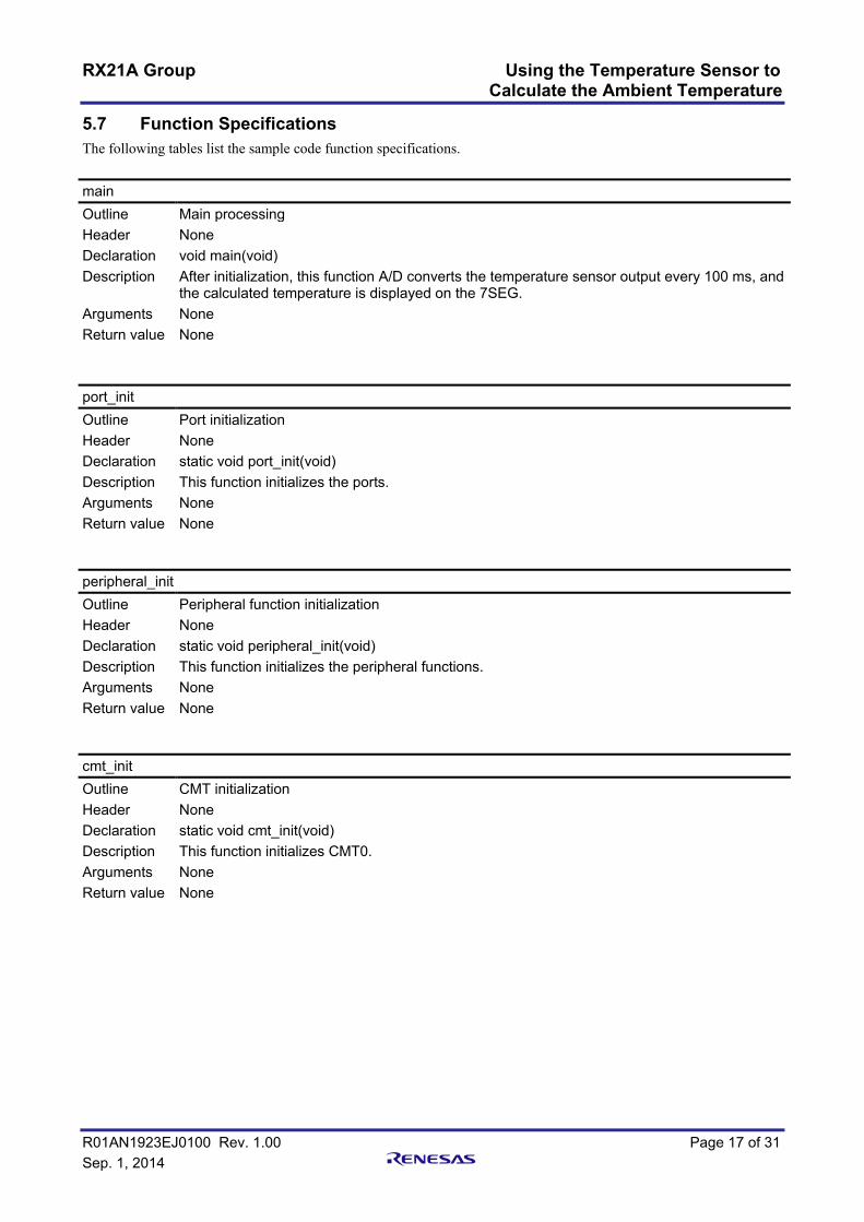
5.7 Function Specifications The following tables list the sample code function specifications.
main Outline Main processing Header None Declaration void main(void) Description After initialization, this function A/D converts the temperature sensor output every 100 ms, and
the calculated temperature is displayed on the 7SEG. Arguments None Return value None
port_init Outline Port initialization Header None Declaration static void port_init(void) Description This function initializes the ports. Arguments None Return value None peripheral_init Outline Peripheral function initialization Header None Declaration static void peripheral_init(void) Description This function initializes the peripheral functions. Arguments None Return value None cmt_init Outline CMT initialization Header None Declaration static void cmt_init(void) Description This function initializes CMT0. Arguments None Return value None

RX21A Group Using the Temperature Sensor to Calculate the Ambient Temperature
R01AN1923EJ0100 Rev. 1.00 Page 18 of 31 Sep. 1, 2014
irq_init Outline IRQ initialization Header None Declaration static void irq_init(void) Description This function initializes IRQ2. Arguments None Return value None disp_7seg Outline Processing to update the 7SEG display data Header None Declaration static void disp_7seg(int16_t disp_data) Description This function sets the value specified in the argument as the data to be displayed in the 7SEG. Arguments int16_t disp_data : 7SEG display
Less than 0 (negative value): "Lo" is displayed 100 or higher: "Hi" is displayed Other than above: Temperature is displayed
Return value None disp_comswitch_7seg Outline Processing to switch the 7SEG select output Header None Declaration static void disp_comswitch_7seg(void) Description This function switches the 7SEG select signal to be output. Arguments None Return value None disp_bar_7seg Outline Processing to display a dash on the 7SEG Header None Declaration static void disp_bar_7seg(void) Description This function displays a dash on the 7SEG. Arguments None Return value None
RX21A Group Using the Temperature Sensor to Calculate the Ambient Temperature
R01AN1923EJ0100 Rev. 1.00 Page 19 of 31 Sep. 1, 2014
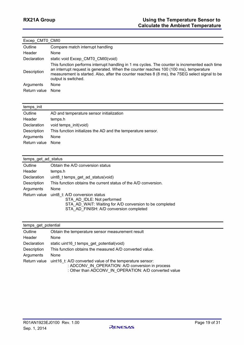
Excep_CMT0_CMI0 Outline Compare match interrupt handling Header None Declaration static void Excep_CMT0_CMI0(void)
Description
This function performs interrupt handling in 1 ms cycles. The counter is incremented each time an interrupt request is generated. When the counter reaches 100 (100 ms), temperature measurement is started. Also, after the counter reaches 8 (8 ms), the 7SEG select signal to be output is switched.
Arguments None Return value None temps_init Outline AD and temperature sensor initialization Header temps.h Declaration void temps_init(void) Description This function initializes the AD and the temperature sensor. Arguments None Return value None temps_get_ad_status Outline Obtain the A/D conversion status Header temps.h Declaration uint8_t temps_get_ad_status(void) Description This function obtains the current status of the A/D conversion. Arguments None Return value uint8_t: A/D conversion status
STA_AD_IDLE: Not performed STA_AD_WAIT: Waiting for A/D conversion to be completed STA_AD_FINISH: A/D conversion completed
temps_get_potential Outline Obtain the temperature sensor measurement result Header None Declaration static uint16_t temps_get_potential(void) Description This function obtains the measured A/D converted value. Arguments None Return value uint16_t: A/D converted value of the temperature sensor:
: ADCONV_IN_OPERATION: A/D conversion in process : Other than ADCONV_IN_OPERATION: A/D converted value
RX21A Group Using the Temperature Sensor to Calculate the Ambient Temperature
R01AN1923EJ0100 Rev. 1.00 Page 20 of 31 Sep. 1, 2014
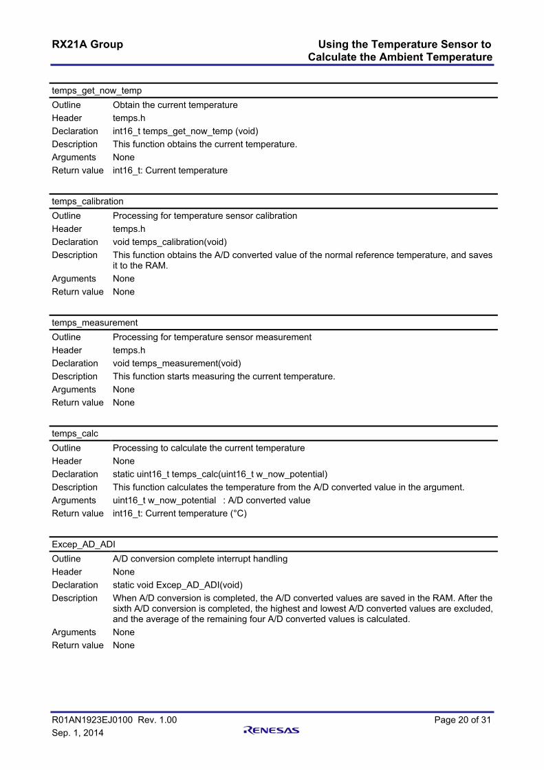
temps_get_now_temp Outline Obtain the current temperature Header temps.h Declaration int16_t temps_get_now_temp (void) Description This function obtains the current temperature. Arguments None Return value int16_t: Current temperature
temps_calibration Outline Processing for temperature sensor calibration Header temps.h Declaration void temps_calibration(void) Description This function obtains the A/D converted value of the normal reference temperature, and saves
it to the RAM. Arguments None Return value None
temps_measurement Outline Processing for temperature sensor measurement Header temps.h Declaration void temps_measurement(void) Description This function starts measuring the current temperature. Arguments None Return value None
temps_calc Outline Processing to calculate the current temperature Header None Declaration static uint16_t temps_calc(uint16_t w_now_potential) Description This function calculates the temperature from the A/D converted value in the argument. Arguments uint16_t w_now_potential : A/D converted value Return value int16_t: Current temperature (°C)
Excep_AD_ADI Outline A/D conversion complete interrupt handling Header None Declaration static void Excep_AD_ADI(void) Description When A/D conversion is completed, the A/D converted values are saved in the RAM. After the
sixth A/D conversion is completed, the highest and lowest A/D converted values are excluded, and the average of the remaining four A/D converted values is calculated.
Arguments None Return value None

RX21A Group Using the Temperature Sensor to Calculate the Ambient Temperature
R01AN1923EJ0100 Rev. 1.00 Page 21 of 31 Sep. 1, 2014
5.8 Flowcharts 5.8.1 Main Processing Figure 5.2 shows the Main Processing.
main
Disable maskable interrupts I flag ← 0
Port initializationport_init()
Stop processing for active peripheral functions after a reset
R_INIT_StopModule()
Nonexistent port initializationR_INIT_NonExistentPort()
Clock initializationR_INIT_Clock()
Peripheral function initializationperipheral_init()
Enable maskable interrupts I flag ← 1
Processing to display a dash on the 7SEG
disp_bar_7seg()
A/D conversioncomplete?
Processing for temperature sensor calibration
temps_calibration()
Obtain the A/D conversion statustemps_get_ad_status()
No
YesObtain the current temperature
temps_get_now_temp() now_temp ← Current temperature
Processing to update the 7SEG display datadisp_7seg()
Figure 5.2 Main Processing

RX21A Group Using the Temperature Sensor to Calculate the Ambient Temperature
R01AN1923EJ0100 Rev. 1.00 Page 22 of 31 Sep. 1, 2014
5.8.2 Port Initialization Figure 5.3 shows Port Initialization.
port_init
Set the 7SEG output ports PORT2.PODR register ← 7Fh: P20 to P26: HighPORTA.PODR register ← 03h: PA0 to PA1: HighPORT2.PDR register ← 7Fh: P20 to P26: OutputPORTA.PDR register ← 03h: PA0 to PA1: Output
return
Figure 5.3 Port Initialization
5.8.3 Peripheral Function Initialization Figure 5.4 shows Peripheral Function Initialization.
main
CMT initializationcmt_init()
IRQ initializationirq_init()
return
Figure 5.4 Peripheral Function Initialization
RX21A Group Using the Temperature Sensor to Calculate the Ambient Temperature
R01AN1923EJ0100 Rev. 1.00 Page 23 of 31 Sep. 1, 2014
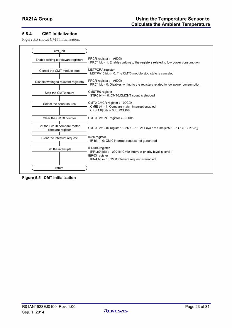
5.8.4 CMT Initialization Figure 5.5 shows CMT Initialization.
cmt_init
Enable writing to relevant registers PRCR register ← A502hPRC1 bit = 1: Enables writing to the registers related to low power consumption
return
Cancel the CMT module stop MSTPCRA registerMSTPA15 bit ← 0: The CMT0 module stop state is canceled
Disable writing to relevant registers PRCR register ← A500hPRC1 bit = 0: Disables writing to the registers related to low power consumption
Stop the CMT0 count CMSTR0 registerSTR0 bit ← 0: CMT0.CMCNT count is stopped
Select the count source CMT0.CMCR register ← 00C0hCMIE bit = 1: Compare match interrupt enabledCKS[1:0] bits = 00b: PCLK/8
Clear the CMT0 counter CMT0.CMCNT register ← 0000h
Set the CMT0 compare match constant register CMT0.CMCOR register ← 2500 - 1: CMT cycle = 1 ms [(2500 - 1) × (PCLKB/8)]
Clear the interrupt request IR28 registerIR bit ← 0: CMI0 interrupt request not generated
Set the interrupts IPR004 registerIPR[3:0] bits ← 0001b: CMI0 interrupt priority level is level 1
IER03 registerIEN4 bit ← 1: CMI0 interrupt request is enabled
Figure 5.5 CMT Initialization

RX21A Group Using the Temperature Sensor to Calculate the Ambient Temperature
R01AN1923EJ0100 Rev. 1.00 Page 24 of 31 Sep. 1, 2014
5.8.5 IRQ Initialization Figure 5.6 shows IRQ Initialization.
irq_init
Disable interrupts IER08 registerIEN2 bit ← 0: IRQ2 interrupt request is disabled
return
Disable the digital filter IRQFLTE0 registerFLTEN2 bit ← 0: Digital filter is disabled.
Set the digital filter sampling clock IRQFLTC0 registerFCLKSEL2[1:0] bits ← 11b: PCLK/64
Set the P32 port mode register PORT3.PMR registerB2 bit ← 0: Use the pin as a general I/O pin.
Enable writing to the PFSWE bit PWPR registerB0WI bit ← 0: Writing to the PFSWE bit is enabled
Enable writing to the PFS register
Set the P32PFS register
Disable writing to the PFS register
Disable writing to the PFSWE bit
PWPR registerPFSWE bit ← 1: Writing to the PFS register is enabled
P32PFS registerISEL bit ← 1: Used as IRQ2 input pin
PWPR registerPFSWE bit ← 0: Writing to the PFS register is disabled
PWPR registerB0WI bit ← 1: Writing to the PFSWE bit is disabled
Set IRQ detection IRQCR2 registerIRQMD[1:0] bits ← 01b: Falling edge
Clear the interrupt request IR066 registerIR bit ← 0: IRQ2 interrupt request is not generated
Enable the digital filter IRQFLTE0 registerFLTEN2 bit ← 1: Digital filter is enabled.
Figure 5.6 IRQ Initialization
RX21A Group Using the Temperature Sensor to Calculate the Ambient Temperature
R01AN1923EJ0100 Rev. 1.00 Page 25 of 31 Sep. 1, 2014
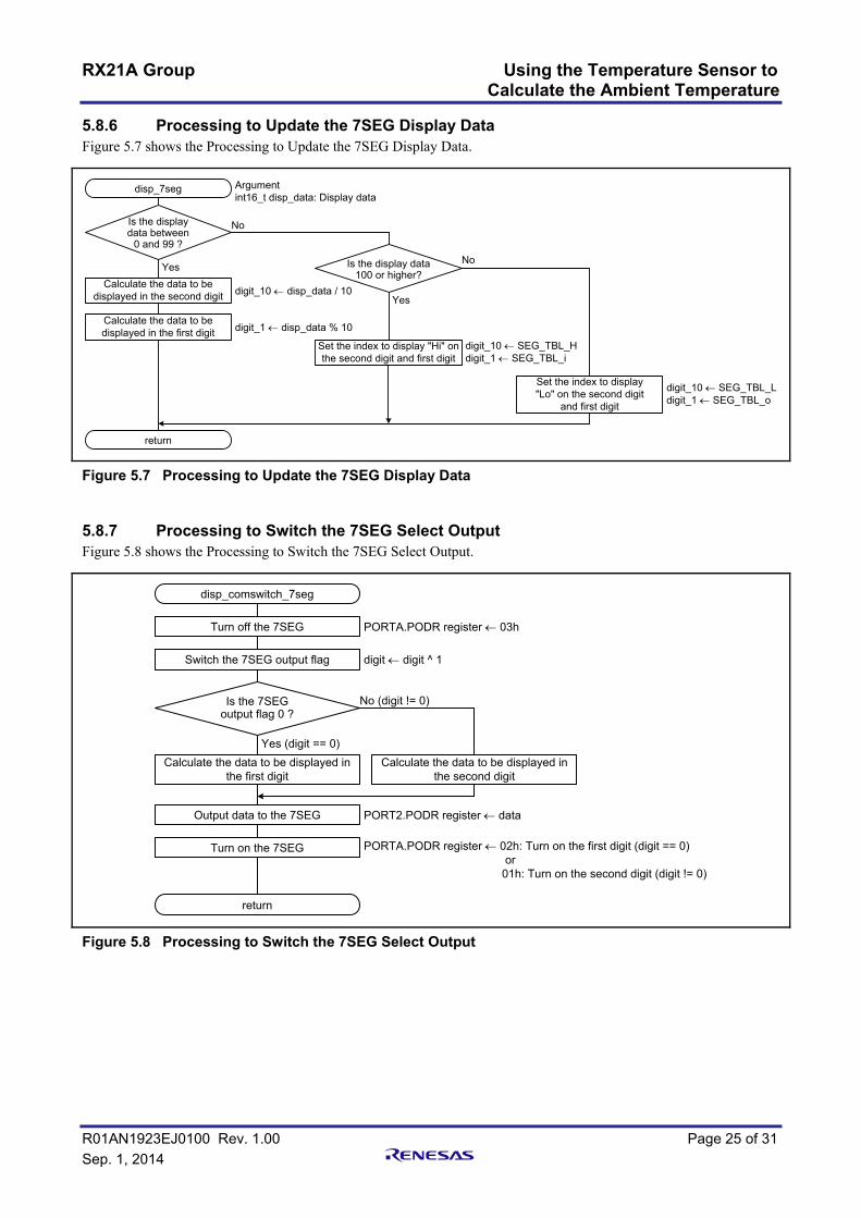
5.8.6 Processing to Update the 7SEG Display Data Figure 5.7 shows the Processing to Update the 7SEG Display Data.
disp_7seg
Calculate the data to be displayed in the second digit
Argumentint16_t disp_data: Display data
No
Yes
digit_10 ← disp_data / 10
Is the displaydata between
0 and 99 ?
Is the display data100 or higher?
Calculate the data to be displayed in the first digit digit_1 ← disp_data % 10
No
Yes
Set the index to display "Hi" on the second digit and first digit
digit_10 ← SEG_TBL_Hdigit_1 ← SEG_TBL_i
Set the index to display"Lo" on the second digit
and first digit
digit_10 ← SEG_TBL_Ldigit_1 ← SEG_TBL_o
return
Figure 5.7 Processing to Update the 7SEG Display Data
5.8.7 Processing to Switch the 7SEG Select Output Figure 5.8 shows the Processing to Switch the 7SEG Select Output.
No (digit != 0)
Yes (digit == 0)
PORTA.PODR register ← 03h
Is the 7SEGoutput flag 0 ?
return
disp_comswitch_7seg
Turn off the 7SEG
digit ← digit ^ 1Switch the 7SEG output flag
Calculate the data to be displayed in the first digit
Calculate the data to be displayed in the second digit
PORT2.PODR register ← dataOutput data to the 7SEG
PORTA.PODR register ← 02h: Turn on the first digit (digit == 0) or 01h: Turn on the second digit (digit != 0)
Turn on the 7SEG
Figure 5.8 Processing to Switch the 7SEG Select Output
RX21A Group Using the Temperature Sensor to Calculate the Ambient Temperature
R01AN1923EJ0100 Rev. 1.00 Page 26 of 31 Sep. 1, 2014
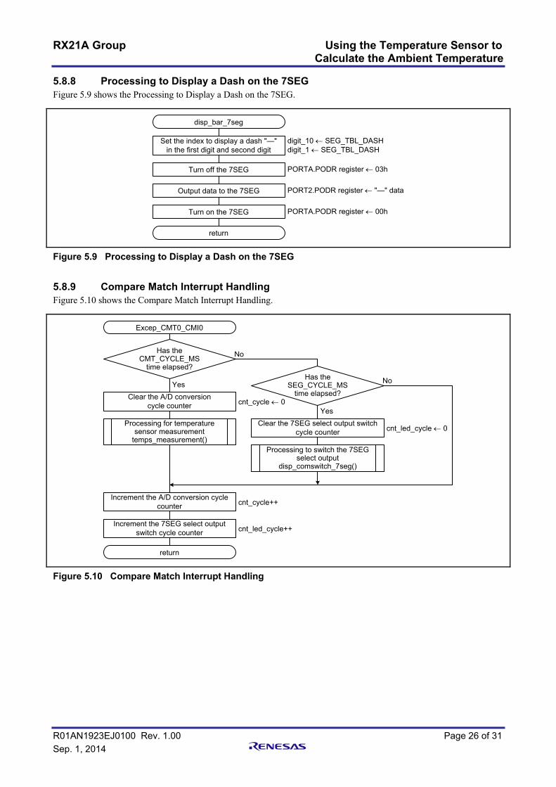
5.8.8 Processing to Display a Dash on the 7SEG Figure 5.9 shows the Processing to Display a Dash on the 7SEG.
disp_bar_7seg
Set the index to display a dash "—"in the first digit and second digit
digit_10 ← SEG_TBL_DASHdigit_1 ← SEG_TBL_DASH
return
Turn off the 7SEG PORTA.PODR register ← 03h
Output data to the 7SEG
Turn on the 7SEG
PORT2.PODR register ← "—" data
PORTA.PODR register ← 00h
Figure 5.9 Processing to Display a Dash on the 7SEG
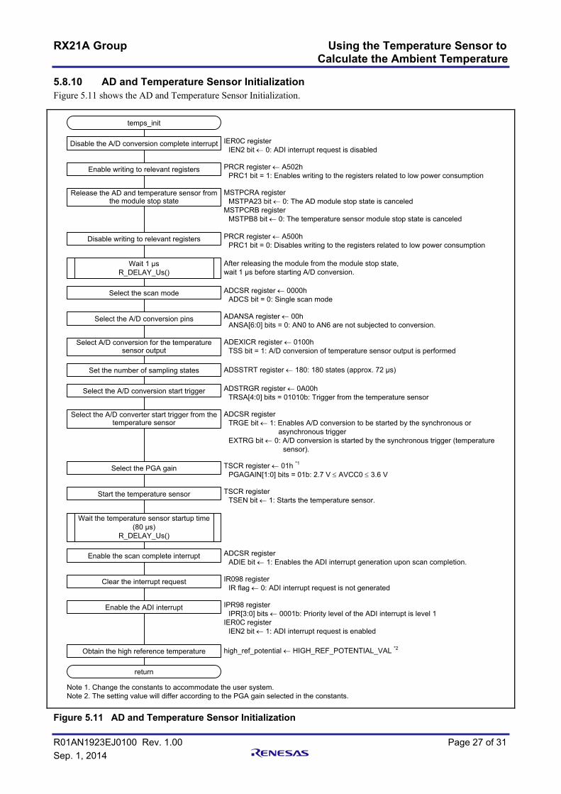
5.8.9 Compare Match Interrupt Handling Figure 5.10 shows the Compare Match Interrupt Handling.
Excep_CMT0_CMI0
Clear the A/D conversioncycle counter
No
Yes
cnt_cycle ← 0
Has theCMT_CYCLE_MS
time elapsed?Has the
SEG_CYCLE_MStime elapsed?
No
YesClear the 7SEG select output switch
cycle counter
Increment the A/D conversion cycle counter
return
Processing for temperature sensor measurement
temps_measurement()cnt_led_cycle ← 0
Processing to switch the 7SEG select output
disp_comswitch_7seg()
cnt_cycle++
Increment the 7SEG select output switch cycle counter cnt_led_cycle++
Figure 5.10 Compare Match Interrupt Handling
RX21A Group Using the Temperature Sensor to Calculate the Ambient Temperature
R01AN1923EJ0100 Rev. 1.00 Page 27 of 31 Sep. 1, 2014
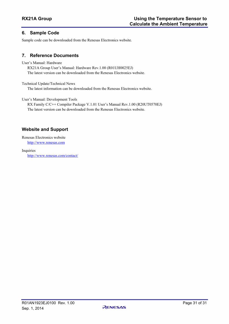
5.8.10 AD and Temperature Sensor Initialization Figure 5.11 shows the AD and Temperature Sensor Initialization.
temps_init
Disable the A/D conversion complete interrupt IER0C registerIEN2 bit ← 0: ADI interrupt request is disabled
Enable writing to relevant registers PRCR register ← A502hPRC1 bit = 1: Enables writing to the registers related to low power consumption
Release the AD and temperature sensor from the module stop state
MSTPCRA registerMSTPA23 bit ← 0: The AD module stop state is canceled
MSTPCRB registerMSTPB8 bit ← 0: The temperature sensor module stop state is canceled
Disable writing to relevant registers PRCR register ← A500hPRC1 bit = 0: Disables writing to the registers related to low power consumption
Wait 1 µsR_DELAY_Us()
After releasing the module from the module stop state, wait 1 µs before starting A/D conversion.
Select the scan mode ADCSR register ← 0000hADCS bit = 0: Single scan mode
Select the A/D conversion pins ADANSA register ← 00hANSA[6:0] bits = 0: AN0 to AN6 are not subjected to conversion.
Select A/D conversion for the temperature sensor output
ADEXICR register ← 0100hTSS bit = 1: A/D conversion of temperature sensor output is performed
Set the number of sampling states ADSSTRT register ← 180: 180 states (approx. 72 µs)
Select the A/D conversion start trigger ADSTRGR register ← 0A00hTRSA[4:0] bits = 01010b: Trigger from the temperature sensor
Select the A/D converter start trigger from the temperature sensor
ADCSR registerTRGE bit ← 1: Enables A/D conversion to be started by the synchronous or
asynchronous triggerEXTRG bit ← 0: A/D conversion is started by the synchronous trigger (temperature
sensor).
Select the PGA gain TSCR register ← 01h *1
PGAGAIN[1:0] bits = 01b: 2.7 V ≤ AVCC0 ≤ 3.6 V
Start the temperature sensor TSCR registerTSEN bit ← 1: Starts the temperature sensor.
Wait the temperature sensor startup time (80 µs)
R_DELAY_Us()
Enable the scan complete interrupt ADCSR registerADIE bit ← 1: Enables the ADI interrupt generation upon scan completion.
Clear the interrupt request IR098 registerIR flag ← 0: ADI interrupt request is not generated
Enable the ADI interrupt IPR98 registerIPR[3:0] bits ← 0001b: Priority level of the ADI interrupt is level 1
IER0C registerIEN2 bit ← 1: ADI interrupt request is enabled
Obtain the high reference temperature high_ref_potential ← HIGH_REF_POTENTIAL_VAL *2
return
Note 1. Change the constants to accommodate the user system.Note 2. The setting value will differ according to the PGA gain selected in the constants.
Figure 5.11 AD and Temperature Sensor Initialization

RX21A Group Using the Temperature Sensor to Calculate the Ambient Temperature
R01AN1923EJ0100 Rev. 1.00 Page 28 of 31 Sep. 1, 2014
5.8.11 Obtain the A/D Conversion Status Figure 5.12 shows Obtain the A/D Conversion Status.
temps_get_ad_status
return (ad_status)
Figure 5.12 Obtain the A/D Conversion Status
5.8.12 Obtain the Temperature Sensor Measurement Result Figure 5.13 shows Obtain the Temperature Sensor Measurement Result.
temps_get_potential
Obtain the A/D converted value w_now_potential ← ADTSDR register value
return(w_now_potential)
Is the PGA stopped?No
Yes
Read the TSCR registerPGAEN bit = 0: Stops PGA.
1: Starts PGA.
Figure 5.13 Obtain the Temperature Sensor Measurement Result
5.8.13 Obtain the Current Temperature Figure 5.14 shows Obtain the Current Temperature.
temps_get_now_temp
return (now_temp)
Figure 5.14 Obtain the Current Temperature

RX21A Group Using the Temperature Sensor to Calculate the Ambient Temperature
R01AN1923EJ0100 Rev. 1.00 Page 29 of 31 Sep. 1, 2014
5.8.14 Processing for Temperature Sensor Calibration Figure 5.15 shows the Processing for Temperature Sensor Calibration.
temps_calibration
Wait for temperature sensor calibration to be executed Read the IR066.IR flag (wait until the flag becomes 1)
return
Clear the IRQ2 interrupt request IR066 registerIR flag ← 0: IRQ2 interrupt request not generated
Start the CMT0 count CMSTR0 registerSTR0 bit ← 1: CMT0.CMCNT count is started
Wait for A/D conversion to be completed
Set the A/D conversion status to "Not performed" ad_status ← STA_AD_IDLE
Save the A/D converted value of the normal reference temperature (25°C) ordinary_potential ← now_potential
Save the A/D converted value slope to the RAM slope_potential ← high_ref_potential – ordinary_potential
Figure 5.15 Processing for Temperature Sensor Calibration
5.8.15 Processing for Temperature Sensor Measurement Figure 5.16 shows the Processing for Temperature Sensor Measurement.
temps_measurement
Start measuring the temperature TSCR registerPGAEN bit ← 1: Starts PGA.
return
AD and temperature sensor initializationtemps_init()
Change the A/D conversion status to "Waiting for A/D conversion to be completed" ad_status ← STA_AD_WAIT
Figure 5.16 Processing for Temperature Sensor Measurement
5.8.16 Processing to Calculate the Current Temperature Figure 5.17 shows the Processing to Calculate the Current Temperature.
temps_calc
Calculate the current temperature *1
Argumentuint16_t w_now_potential: A/D converted value
return(w_now_temp)
Note 1. Refer to section 5.1.1 Formula for the Temperature Characteristic for details on the formula.
Figure 5.17 Processing to Calculate the Current Temperature

RX21A Group Using the Temperature Sensor to Calculate the Ambient Temperature
R01AN1923EJ0100 Rev. 1.00 Page 30 of 31 Sep. 1, 2014
5.8.17 A/D Conversion Complete Interrupt Handling Figure 5.18 shows the A/D Conversion Complete Interrupt Handling.
Excep_AD_ADI
Update the lowest value ad_min_value ← A/D converted value
return
Is the status of the A/Dconversion "Waiting for A/D conversion
to be completed"?
No (ad_status != STA_AD_WAIT)
Yes (ad_status == STA_AD_WAIT)
Obtain the temperature sensor measurement result
temps_get_potential()now_potential ← A/D converted value
Is the A/Dconverted value obtained the
lowest value?
No
Yes
Is the A/Dconverted value obtained the
highest value?
No
Yes
Update the highest value ad_max_value ← A/D converted value
Save the A/D converted value in the buffer
Is the number ofA/D converted values obtained less
than CNV_CNT_MAX?
No
YesIncrement the number of A/D converted values
obtained
Stop the temperature sensor TSCR registerTSEN bit ← 0: Stops the temperature sensor.
Total the A/D conversion data for the number of times specified in
CNV_CNT_MAX
Subtract the lowest and highest values from the total
Calculate the average from the result of the previous process
Save the calculated average in the RAM now_potential ← Average value
Processing to calculate the current temperature
temps_calc()
Set the status of the A/Dconversion to "A/D conversion
completed"ad_status ← STA_AD_FINISH
Initialize the lowest and highest values
Initialize the number of A/D conversions
Figure 5.18 A/D Conversion Complete Interrupt Handling
RX21A Group Using the Temperature Sensor to Calculate the Ambient Temperature
R01AN1923EJ0100 Rev. 1.00 Page 31 of 31 Sep. 1, 2014
6. Sample Code Sample code can be downloaded from the Renesas Electronics website.
7. Reference Documents User’s Manual: Hardware
RX21A Group User’s Manual: Hardware Rev.1.00 (R01UH0025EJ) The latest version can be downloaded from the Renesas Electronics website.
Technical Update/Technical News
The latest information can be downloaded from the Renesas Electronics website. User’s Manual: Development Tools
RX Family C/C++ Compiler Package V.1.01 User’s Manual Rev.1.00 (R20UT0570EJ) The latest version can be downloaded from the Renesas Electronics website.
Website and Support Renesas Electronics website
http://www.renesas.com Inquiries
http://www.renesas.com/contact/

A-1
REVISION HISTORY RX21A Group Application Note
Using the Temperature Sensor to Calculate the Ambient Temperature
Rev. Date Description
Page Summary 1.00 Sep. 1, 2014 — First edition issued
All trademarks and registered trademarks are the property of their respective owners.

General Precautions in the Handling of MPU/MCU Products The following usage notes are applicable to all MPU/MCU products from Renesas. For detailed usage notes on the products covered by this document, refer to the relevant sections of the document as well as any technical updates that have been issued for the products.
1. Handling of Unused Pins Handle unused pins in accordance with the directions given under Handling of Unused Pins in the manual. The input pins of CMOS products are generally in the high-impedance state. In operation with an
unused pin in the open-circuit state, extra electromagnetic noise is induced in the vicinity of LSI, an associated shoot-through current flows internally, and malfunctions occur due to the false recognition of the pin state as an input signal become possible. Unused pins should be handled as described under Handling of Unused Pins in the manual.
2. Processing at Power-on The state of the product is undefined at the moment when power is supplied. The states of internal circuits in the LSI are indeterminate and the states of register settings and
pins are undefined at the moment when power is supplied. In a finished product where the reset signal is applied to the external reset pin, the states of pins are not guaranteed from the moment when power is supplied until the reset process is completed. In a similar way, the states of pins in a product that is reset by an on-chip power-on reset function are not guaranteed from the moment when power is supplied until the power reaches the level at which resetting has been specified.
3. Prohibition of Access to Reserved Addresses Access to reserved addresses is prohibited. The reserved addresses are provided for the possible future expansion of functions. Do not access
these addresses; the correct operation of LSI is not guaranteed if they are accessed. 4. Clock Signals
After applying a reset, only release the reset line after the operating clock signal has become stable. When switching the clock signal during program execution, wait until the target clock signal has stabilized. When the clock signal is generated with an external resonator (or from an external oscillator)
during a reset, ensure that the reset line is only released after full stabilization of the clock signal. Moreover, when switching to a clock signal produced with an external resonator (or by an external oscillator) while program execution is in progress, wait until the target clock signal is stable.
5. Differences between Products Before changing from one product to another, i.e. to a product with a different part number, confirm that the change will not lead to problems. The characteristics of an MPU or MCU in the same group but having a different part number may
differ in terms of the internal memory capacity, layout pattern, and other factors, which can affect the ranges of electrical characteristics, such as characteristic values, operating margins, immunity to noise, and amount of radiated noise. When changing to a product with a different part number, implement a system-evaluation test for the given product.

Notice1. Descriptions of circuits, software and other related information in this document are provided only to illustrate the operation of semiconductor products and application examples. You are fully responsible for
the incorporation of these circuits, software, and information in the design of your equipment. Renesas Electronics assumes no responsibility for any losses incurred by you or third parties arising from the
use of these circuits, software, or information.
2. Renesas Electronics has used reasonable care in preparing the information included in this document, but Renesas Electronics does not warrant that such information is error free. Renesas Electronics
assumes no liability whatsoever for any damages incurred by you resulting from errors in or omissions from the information included herein.
3. Renesas Electronics does not assume any liability for infringement of patents, copyrights, or other intellectual property rights of third parties by or arising from the use of Renesas Electronics products or
technical information described in this document. No license, express, implied or otherwise, is granted hereby under any patents, copyrights or other intellectual property rights of Renesas Electronics or
others.
4. You should not alter, modify, copy, or otherwise misappropriate any Renesas Electronics product, whether in whole or in part. Renesas Electronics assumes no responsibility for any losses incurred by you or
third parties arising from such alteration, modification, copy or otherwise misappropriation of Renesas Electronics product.
5. Renesas Electronics products are classified according to the following two quality grades: "Standard" and "High Quality". The recommended applications for each Renesas Electronics product depends on
the product's quality grade, as indicated below.
"Standard": Computers; office equipment; communications equipment; test and measurement equipment; audio and visual equipment; home electronic appliances; machine tools; personal electronic
equipment; and industrial robots etc.
"High Quality": Transportation equipment (automobiles, trains, ships, etc.); traffic control systems; anti-disaster systems; anti-crime systems; and safety equipment etc.
Renesas Electronics products are neither intended nor authorized for use in products or systems that may pose a direct threat to human life or bodily injury (artificial life support devices or systems, surgical
implantations etc.), or may cause serious property damages (nuclear reactor control systems, military equipment etc.). You must check the quality grade of each Renesas Electronics product before using it
in a particular application. You may not use any Renesas Electronics product for any application for which it is not intended. Renesas Electronics shall not be in any way liable for any damages or losses
incurred by you or third parties arising from the use of any Renesas Electronics product for which the product is not intended by Renesas Electronics.
6. You should use the Renesas Electronics products described in this document within the range specified by Renesas Electronics, especially with respect to the maximum rating, operating supply voltage
range, movement power voltage range, heat radiation characteristics, installation and other product characteristics. Renesas Electronics shall have no liability for malfunctions or damages arising out of the
use of Renesas Electronics products beyond such specified ranges.
7. Although Renesas Electronics endeavors to improve the quality and reliability of its products, semiconductor products have specific characteristics such as the occurrence of failure at a certain rate and
malfunctions under certain use conditions. Further, Renesas Electronics products are not subject to radiation resistance design. Please be sure to implement safety measures to guard them against the
possibility of physical injury, and injury or damage caused by fire in the event of the failure of a Renesas Electronics product, such as safety design for hardware and software including but not limited to
redundancy, fire control and malfunction prevention, appropriate treatment for aging degradation or any other appropriate measures. Because the evaluation of microcomputer software alone is very difficult,
please evaluate the safety of the final products or systems manufactured by you.
8. Please contact a Renesas Electronics sales office for details as to environmental matters such as the environmental compatibility of each Renesas Electronics product. Please use Renesas Electronics
products in compliance with all applicable laws and regulations that regulate the inclusion or use of controlled substances, including without limitation, the EU RoHS Directive. Renesas Electronics assumes
no liability for damages or losses occurring as a result of your noncompliance with applicable laws and regulations.
9. Renesas Electronics products and technology may not be used for or incorporated into any products or systems whose manufacture, use, or sale is prohibited under any applicable domestic or foreign laws or
regulations. You should not use Renesas Electronics products or technology described in this document for any purpose relating to military applications or use by the military, including but not limited to the
development of weapons of mass destruction. When exporting the Renesas Electronics products or technology described in this document, you should comply with the applicable export control laws and
regulations and follow the procedures required by such laws and regulations.
10. It is the responsibility of the buyer or distributor of Renesas Electronics products, who distributes, disposes of, or otherwise places the product with a third party, to notify such third party in advance of the
contents and conditions set forth in this document, Renesas Electronics assumes no responsibility for any losses incurred by you or third parties as a result of unauthorized use of Renesas Electronics
products.
11. This document may not be reproduced or duplicated in any form, in whole or in part, without prior written consent of Renesas Electronics.
12. Please contact a Renesas Electronics sales office if you have any questions regarding the information contained in this document or Renesas Electronics products, or if you have any other inquiries.
(Note 1) "Renesas Electronics" as used in this document means Renesas Electronics Corporation and also includes its majority-owned subsidiaries.
(Note 2) "Renesas Electronics product(s)" means any product developed or manufactured by or for Renesas Electronics.
http://www.renesas.comRefer to "http://www.renesas.com/" for the latest and detailed information.
Renesas Electronics America Inc.2801 Scott Boulevard Santa Clara, CA 95050-2549, U.S.A.Tel: +1-408-588-6000, Fax: +1-408-588-6130Renesas Electronics Canada Limited1101 Nicholson Road, Newmarket, Ontario L3Y 9C3, CanadaTel: +1-905-898-5441, Fax: +1-905-898-3220Renesas Electronics Europe LimitedDukes Meadow, Millboard Road, Bourne End, Buckinghamshire, SL8 5FH, U.KTel: +44-1628-585-100, Fax: +44-1628-585-900Renesas Electronics Europe GmbHArcadiastrasse 10, 40472 Düsseldorf, GermanyTel: +49-211-6503-0, Fax: +49-211-6503-1327Renesas Electronics (China) Co., Ltd.Room 1709, Quantum Plaza, No.27 ZhiChunLu Haidian District, Beijing 100191, P.R.ChinaTel: +86-10-8235-1155, Fax: +86-10-8235-7679Renesas Electronics (Shanghai) Co., Ltd.Unit 301, Tower A, Central Towers, 555 Langao Road, Putuo District, Shanghai, P. R. China 200333Tel: +86-21-2226-0888, Fax: +86-21-2226-0999Renesas Electronics Hong Kong LimitedUnit 1601-1613, 16/F., Tower 2, Grand Century Place, 193 Prince Edward Road West, Mongkok, Kowloon, Hong KongTel: +852-2265-6688, Fax: +852 2886-9022/9044Renesas Electronics Taiwan Co., Ltd.13F, No. 363, Fu Shing North Road, Taipei 10543, TaiwanTel: +886-2-8175-9600, Fax: +886 2-8175-9670Renesas Electronics Singapore Pte. Ltd.80 Bendemeer Road, Unit #06-02 Hyflux Innovation Centre, Singapore 339949Tel: +65-6213-0200, Fax: +65-6213-0300Renesas Electronics Malaysia Sdn.Bhd.Unit 906, Block B, Menara Amcorp, Amcorp Trade Centre, No. 18, Jln Persiaran Barat, 46050 Petaling Jaya, Selangor Darul Ehsan, MalaysiaTel: +60-3-7955-9390, Fax: +60-3-7955-9510Renesas Electronics Korea Co., Ltd.12F., 234 Teheran-ro, Gangnam-Ku, Seoul, 135-920, KoreaTel: +82-2-558-3737, Fax: +82-2-558-5141
SALES OFFICES
© 2014 Renesas Electronics Corporation. All rights reserved. Colophon 4.0