Embed Size (px)
Citation preview

RELIABLE | PRECISE | COMPACT
THE COUPLING.RW-COUPLINGS.COM
PRECISION COUPLINGSEXACT AND BACKLASH FREE FOR PRECISION SERVO AND STEPPER DRIVE APPLICATIONS.
R+W_Produktkatalog_Aufl3_BK_MK_Teil1_EN.indd 1 23.10.14 14:00

22
WHO WE ARE.
ABOVE ALL R+W IS:THE PERFECT COUPLING.
WE PROVIDE INSPIRED SOLUTIONS BACKED BY SOUND PLANNING AND DESIGN.
R+W stands for expertise in the development of solutions for precise torque transmission. The focus of our development is on innovative coupling systems for all sectors of precision drive technology. As a leading manufacturer of precision couplings and line shafts, we strive to maintain a permanent status of technology leadership in our field. Our central claim: R+W couplings ensure precision for process reliability and efficiency, and to that end we seek perfection.
Optimized for technology and business, our product portfolio includes:
Bellows couplings
Elastomer insert couplings
Ball-detent safety couplings
Line shaft couplings
High torque industrial couplings
Development of customized solutions with collaboration from start to finish, including:
– Consultation – Conception – Engineering analysis – Prototyping – Manufacturing
When R+W Antriebselemente GmbH was first established in 1990 in Klingenberg, Germany, there were three people on board. The head office is still there, but we are now more than 170 people, with subsidiaries in the USA, China, Italy, Singapore, France and Slovakia, and are partnered with over 60 well established distributors in more than 40 countries throughout the world. Many developments have lead to this success, but most importantly it was brought about by our endless search for the best possible coupling solutions as well as the high esteem in which we hold all of our customers.
R+W_Produktkatalog_Aufl3_BK_MK_Teil1_EN.indd 2 23.10.14 14:00

333
DRIVE
D - DYNAMIC
Our staff is trained to always be ready and willing to provide a quick reaction to customer inquiries. Our product, the core of which is based on handling high performance, dy-namic applications, is increasingly available for fast delivery.
R - RELIABLE
Many of our products are designed for infinite life with zero maintenance required. With thorough engineer-ing processes in place, and an ISO 9001:2008 certified production facility, we continue to deliver high quality coupling products with a high level of reliability.
I - INNOVATIVE
Our business was founded on developing unique and inno-vative solutions to common coupling problems. Our staff in turn is constantly developing its work flows to stream-line delivery and simplify the process for our customers.
V - VERSATILE
With products successfully applied and deployed in over 125 industry segments, chances are very good that we have an expert on our versatile staff that is familiar with your application requirements.
E - EXPANDING
With double digit annual growth the norm, our company is ever expanding, adding new product offerings and opening new service centers throughout the world all the time.
RW-COUPLINGS.COM
OTHER R+W COUPLINGSAside from the products detailed in this catalog, we also offer quality shaft couplings and torque limiters for high powered industrial drives.
More information on these can be found in our industrial couplings catalog.
R+W_Produktkatalog_Aufl3_BK_MK_Teil1_EN.indd 3 23.10.14 11:51

SIZI
NG
9RW-COUPLINGS.COMRW-COUPLINGS.COM
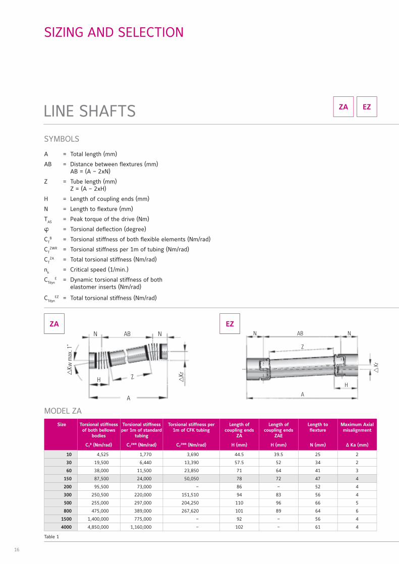
SIZING AND SELECTION
According to DIN 740 part 2
R+W_Produktkatalog_Aufl3_BK_MK_Teil1_EN.indd 9 23.10.14 11:51
16
SYMBOLS
A = Total length (mm)
AB = Distance between flextures (mm) AB = (A – 2xN)
Z = Tube length (mm) Z = (A – 2xH)
H = Length of coupling ends (mm)
N = Length to flexture (mm)
TAS = Peak torque of the drive (Nm)
φ = Torsional deflection (degree)
CTB = Torsional stiffness of both flexible elements (Nm/rad)
CTZWR = Torsional stiffness per 1m of tubing (Nm/rad)
CTZA = Total torsional stiffness (Nm/rad)
nk = Critical speed (1/min.)
CTdynE = Dynamic torsional stiffness of both
elastomer inserts (Nm/rad)
CTdynEZ = Total torsional stiffness (Nm/rad)
ZA
MODEL ZA
Size Torsional stiffness of both bellows
bodies
Torsional stiffness per 1m of standard
tubing
Torsional stiffness per 1m of CFK tubing
Length of coupling ends
ZA
Length of coupling ends
ZAE
Length to flexture
Maximum Axial misalignment
CTB (Nm/rad) CT
ZWR (Nm/rad) CTZWR (Nm/rad) H (mm) H (mm) N (mm) Δ Ka (mm)
10 4,525 1,770 3,690 44.5 39.5 25 2
30 19,500 6,440 13,390 57.5 52 34 2
60 38,000 11,500 23,850 71 64 41 3
150 87,500 24,000 50,050 78 72 47 4
200 95,500 73,000 – 86 – 52 4
300 250,500 220,000 151,510 94 83 56 4
500 255,000 297,000 204,250 110 96 66 5
800 475,000 389,000 267,620 101 89 64 6
1500 1,400,000 775,000 – 92 – 56 4
4000 4,850,000 1,160,000 – 102 – 61 4
EZ
SIZING AND SELECTION
LINE SHAFTS
ZA EZ
A
N AB
Z
H
Kr
N
Table 1
R+W_Produktkatalog_Aufl3_BK_MK_Teil1_EN.indd 16 23.10.14 11:51
RW-COUPLINGS.COM
MO
DEL
LREI
HEN
AT
EXM
OD
ELLR
EIH
EN
LPM
OD
ELLR
EIH
EN
ZA |
EZ
MO
DEL
LREI
HEN
SK
| E
S |
SL
MO
DEL
LREI
HEN
EK
| T
XM
OD
ELLR
EIH
EN
MK
MO
DEL
LREI
HEN
BK
EIN
BAU
HIN
WEI
SESI
ZIN
G
17
Size Ø 6 Ø 8 Ø 12 Ø 16 Ø 19 Ø 25 Ø 30 Ø 32 Ø 35 Ø 45 Ø 50 Ø 55 Ø 60 Ø 65 Ø 70 Ø 75 Ø 80 Ø 90 Ø 120 Ø 140
5 4 10 15
10 6 12 20 32
20 30 35 40 50 65
60 65 120 150 180 200
150 180 240 270 300 330
300 300 340 450 520 570 630
450 630 720 770 900 1120 1180 1350
800 1050 1125 1200 1300 1400 1450 1500 1550 1600
2500 1900 2600 2900 3200 3500 3800 4000 4300 4600 5200
4500 5300 5800 6300 7000 7600 8200 8800 9400 10600 14100
9500 9200 10100 11100 11900 12800 13800 14800 16700 22000 25600
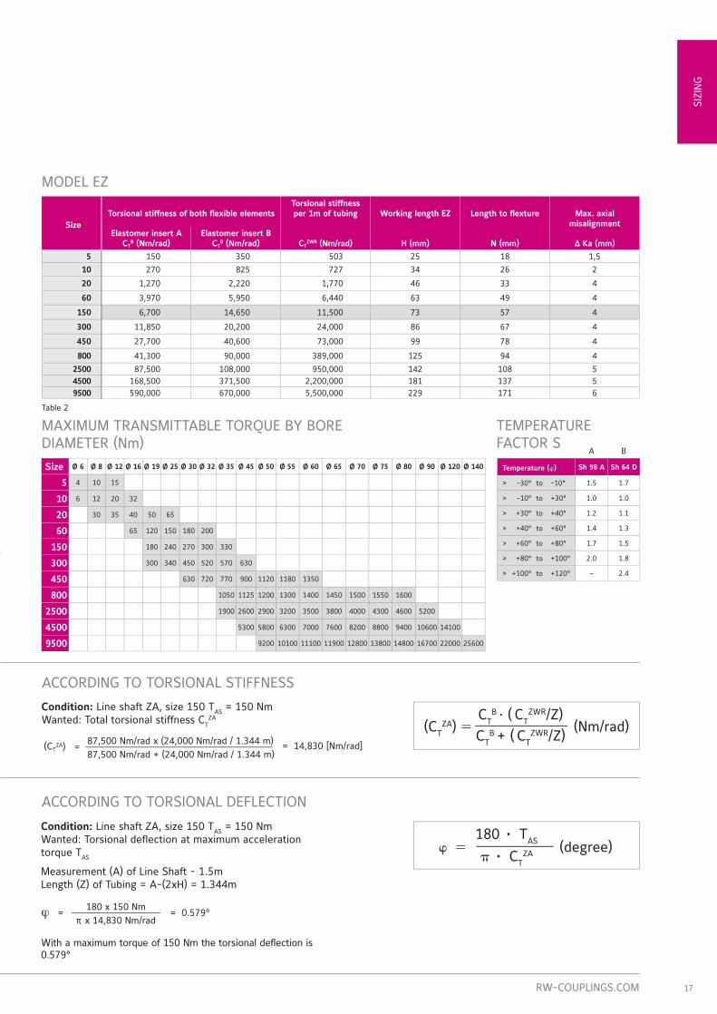
ACCORDING TO TORSIONAL STIFFNESS
ACCORDING TO TORSIONAL DEFLECTION
φ = (degree)180 • TAS
π • CTZA
MODEL EZ
SizeTorsional stiffness of both flexible elements
Torsional stiffness per 1m of tubing Working length EZ Length to flexture Max. axial
misalignmentElastomer insert A
CTB (Nm/rad)
Elastomer insert BCT
B (Nm/rad) CTZWR (Nm/rad) H (mm) N (mm) Δ Ka (mm)
5 150 350 503 25 18 1,5
10 270 825 727 34 26 2
20 1,270 2,220 1,770 46 33 4
60 3,970 5,950 6,440 63 49 4
150 6,700 14,650 11,500 73 57 4
300 11,850 20,200 24,000 86 67 4
450 27,700 40,600 73,000 99 78 4
800 41,300 90,000 389,000 125 94 4
2500 87,500 108,000 950,000 142 108 54500 168,500 371,500 2,200,000 181 137 59500 590,000 670,000 5,500,000 229 171 6
MAXIMUM TRANSMITTABLE TORQUE BY BORE DIAMETER (Nm)
TEMPERATURE FACTOR S
A B
Temperature (φ) Sh 98 A Sh 64 D
> -30° to -10° 1.5 1.7
> -10° to +30° 1.0 1.0
> +30° to +40° 1.2 1.1
> +40° to +60° 1.4 1.3
> +60° to +80° 1.7 1.5
> +80° to +100° 2.0 1.8
> +100° to +120° – 2.4
(CTZA) = (Nm/rad)
CTB · ( CT
ZWR/Z)CT
B + ( CTZWR/Z)
With a maximum torque of 150 Nm the torsional deflection is 0.579°
Table 2
Condition: Line shaft ZA, size 150 TAS = 150 NmWanted: Torsional deflection at maximum acceleration torque TAS
Measurement (A) of Line Shaft - 1.5mLength (Z) of Tubing = A-(2xH) = 1.344m
Condition: Line shaft ZA, size 150 TAS = 150 NmWanted: Total torsional stiffness CT
ZA
(CTZA) =
87,500 Nm/rad x (24,000 Nm/rad / 1.344 m)87,500 Nm/rad + (24,000 Nm/rad / 1.344 m)
= 14,830 [Nm/rad]
= 0.579°180 x 150 Nm
π x 14,830 Nm/radϕ =
R+W_Produktkatalog_Aufl3_BK_MK_Teil1_EN.indd 17 23.10.14 11:51

18
ZA EZ
SIZING AND SELECTION
LINE SHAFTS
Using proprietary software, R+W will calculate the specific mechanical details of exactly the model you plan to use. Overall length, tube materials (e.g. steel, aluminum, CFK), and other factors are used to determine a number of per-formance values unique to your line shaft coupling.
Critical speed nk = 1/min.Torsional stiffness of tubing CT
ZWR = Nm/radOverall stiffness CT
ZA = Nm/radTorsional deflection ϕ = degree-min-secTotal Weight m = kgMoment of inertia J = kgm2
Maximum misalignment Kr = mm
R+W CALCULATION PROGRAM
ACCORDING TO MAXIMUM MISALIGNMENT
Lateral misalignment Kr Axial misalignment KaAngular misalignment Kw
See table 1+2Pages 16+17
Kwmax. = 2°Δ Krmax = tan Δ Kw · AB
AB = A – 2xN2
ZA
EZ
R+W_Produktkatalog_Aufl3_BK_MK_Teil1_EN.indd 18 23.10.14 11:51

LIN
E SH
AFT
S ZA
| E
Z
113RW-COUPLINGS.COMRW-COUPLINGS.COM
SIZES FROM 9 - 25,000 NmLINE SHAFT COUPLINGS
GENERAL INFORMATION R+W LINE SHAFT COUPLINGS:
SERVICE LIFER+W line shaft couplings are wear and maintenance free for an infinite service life, as long as the technical limits are not exceeded.
FIT CLEARANCE Overall shaft / hub clearance of 0.01 - 0.05 mm
ROTATIONAL SPEEDAfter selecting overall length A, contact R+W for maximum speed.
SPECIAL SOLUTIONSVarious materials, tolerances, dimensions and performance ratings available for custom applications on request.
ATEX (Optional)For use in hazardous zones 1/21 and 2/22, R+W line shaft couplings have been authorized under directive 94/9/EG and is available with certification.
ZA EZ
Optional:
R+W_Produktkatalog_Aufl3_ZA_Teil4_EN.indd 113 23.10.14 13:53

114
BACKLASH FREE, TORSIONALLY STIFF
LINE SHAFT COUPLINGSSIZES FROM 10 - 4,000 Nm
with clamping hubfrom 10 - 800 Nm
installation and removal possible without disturbing other machine components standard lengths up to 6 meters no intermediate support bearings required
with fully split clamping hubfrom 10 - 800 Nm
complete coupling system mounts laterally for very easy installation and removal standard lengths up to 6 meters, with CFK tube no intermediate support bearings required
ZA
ZA
ZAL
FEATURESMODEL
with conical clamping systemfrom 1,500 - 4,000 Nm
installation and removal possible without disturbing other machine components standard lengths up to 6 meters no intermediate support bearings required
ZA
Page 116
with fully split clamping hubfrom 10 - 800 Nm
complete coupling system mounts laterally for very easy installation and removal standard lengths up to 6 meters no intermediate support bearings required
ZAEPage 118
Page 117
Page 119
R+W_Produktkatalog_Aufl3_ZA_Teil4_EN.indd 114 23.10.14 13:53

RW-COUPLINGS.COM
LIN
E SH
AFT
S ZA
| E
Z
115
EZ
BACKLASH FREE LINE SHAFT COUPLINGSSIZES FROM 9 - 25,000 Nm
with fully split clamping hubfrom 9 - 25,000 Nm
standard lengths up to 4 meters no intermediate support bearings required complete coupling system mounts later-ally for very easy installation and removal
EZ2
FEATURESMODEL
Pages 120-121
with fully split clamping hub, adjustable lengthfrom 12.5 - 1,200 Nm
adjustable length ranges up to 4 meters no intermediate support bearings required complete coupling system mounts later-ally for very easy installation and removal
EZVPages 122-123
R+W_Produktkatalog_Aufl3_ZA_Teil4_EN.indd 115 23.10.14 13:53

116
ZA WITH CLAMPING HUB10 - 800 Nm
MODEL ZASIZE 10 30 60 150 200 300 500 800Rated torque (Nm) TKN 10 30 60 150 200 300 500 800
Overall length min. to max. (mm) A-2 110 - 6000 140 - 6000 170 - 6000 190 - 6000 210 - 6000 250 - 6000 260 - 6000 260 - 6000
Outside diameter clamping hub (mm) B 40 55 66 81 90 110 123 134
Fit length (mm) C 16 27 31 35.5 40.5 43 50 48
Inside diameterfrom Ø to Ø H7 (mm) D1/2 5 - 20 10 - 28 12 - 32 19 - 42 22 - 45 30 - 60 35 - 60 40 - 72
With keyway max. Ø H7 (mm) D1/2 17 23 29 36 45 60 60 66
ISO 4762 clamping screwE
M4 M6 M8 M10 M12 M12 M16 2x M16
Tightening torque (Nm) 5 15 40 70 110 130 200 250
Distance between centers (mm) F 15 19 23 27 31 39 41 48
Distance (mm) G 5 7.5 9.5 11 12.5 13 17 18
Length bellows body (mm) H 44.5 57.5 71 78 86 94 110 101
Distance (mm) I 38.5 51 61 69 75.5 81 96 89
ISO 4762 clamping screwJ
4x M4 6x M4 6x M5 8x M6 8x M6 8x M8 8x M8 10x M8
Tightening torque (Nm) 3 4 7 10 12 30 30 40
Outside diameter tube section (mm) K 35 50 60 76 90 100 110 120
Bolt hole circle Ø (mm) L 45 62.5 71.5 88 100 120 132 138
Outside diameter flange (mm) M 52 70 80 98 110 135 148 153
Shaft average value (mm) N 25 34 41 47 52 56 66 64
ORDERING EXAMPLE ZA 10 1551 18 19.05 XXModel
Special designation only (e.g. special bore
tolerance).
Size
Overall length mm
Bore D1 H7
Bore D2 H7
For custom features place an XX at the end of the part number and describe the special requirements (e.g. ZA / 10 / 1551 / 18 / 19.05 / XX; XX=anodized aluminum)
For maximum misalignment values see page 16.
FEATURES for spanning larger distances between shaft ends standard lengths up to 6 meters no intermediate support bearings required extremely straight and laterally stiff intermediate tube
MATERIAL Bellows: high grade stainless steel
Intermediate tube: up to size 150 aluminum, size 300 and up steel, optional CFK Hubs: up to size 60 aluminum, size 150 and up steel
DESIGNTwo clamping hubs with a single clamp-ing screw in each. A special support system carries the weight of the tube on the hubs. Operable temperature range from -30 to +100 ˚C.
ABOUT
II
Ø D
1H7
Ø D
2H7
H
NGG
H
NJ ISO 4762
C C
A-2
Ø M
E ISO 4762
F
DIN or ANSI keyway
optional
All data subject to change without notice.
Ø K
R+W_Produktkatalog_Aufl3_ZA_Teil4_EN.indd 116 23.10.14 13:53

RW-COUPLINGS.COM
LIN
E SH
AFT
S ZA
| E
Z
117All data subject to change without notice.
ZA WITH CONICAL CLAMPING SYSTEM1,500 - 4,000 Nm
MODEL ZASIZE 1500 4000Rated torque (Nm) TKN 1500 4000
Overall length min. to max. (mm) A±3 280 - 6000 280 - 6000
Outside diameter (mm) B 157 200
Fit length (mm) C 61 80.5
Inside diameter from Ø to Ø H7 (mm) D1/2 35 - 70 40 - 100
ISO 4017 clamping screwsE
6 x M12 6 x M16
Tightening torque (Nm) 70 120
Length bellows body (mm) H 98 103.5
Distance (mm) I 82 84
ISO 4762 clamping screwsJ
10x M10 12x M12
Tightening torque (Nm) 70 120
Outside diameter tube section (mm) K 150 160
Bolt hole circle Ø (mm) L 168 193
Outside diameter flange (mm) M 184 213
Shaft average value (mm) N 56 61
Ø M
LK Ø
L
3x jack screws for removal
E ISO 4017
FEATURES for spanning larger distances between shaft ends standard lengths up to 6 meters no intermediate support bearings required extremely straight and laterally stiff intermediate tube
MATERIAL Bellows: high grade stainless steel
Intermediate tube: steel, optional CFK Hubs: steel
DESIGNTwo conical clamping bushings with separate screws for mounting and dismounting. A special support system carries the weight of the tube on the hubs. Operable temperature range from -30 to +120 ˚C.
ABOUT
I I
Ø D
1H7
Ø D
2H7
Ø B
H HNN
CC
A±3
J ISO 4762
ORDERING EXAMPLE ZA 1500 2551 50.8 70 XXModel
Special designation only (e.g. special bore
tolerance).
Size
Overall length mm
Bore D1 H7
Bore D2 H7
For custom features place an XX at the end of the part number and describe the special requirements (e.g. ZA / 1500 / 2551 / 50.8 / 70 / XX; XX=stainless steel)
For maximum misalignment values see page 16.
Ø K
R+W_Produktkatalog_Aufl3_ZA_Teil4_EN.indd 117 23.10.14 13:53

118 All data subject to change without notice.
ORDERING EXAMPLE ZAE 10 1551 18 19.05 XXModel
Special designation only (e.g. special bore
tolerance).
Size
Overall length mm
Bore D1 H7
Bore D2 H7
For custom features place an XX at the end of the part number and describe the special requirements (e.g. ZAE / 10 / 1551 / 18 / 19.05 / XX; XX=anodized aluminum)
For maximum misalignment values see page 16.
ZAE WITH FULLY SPLIT CLAMPING HUB10 - 800 Nm
FEATURES for spanning larger distances between shaft ends
standard lengths up to 6 meters no intermediate support bearings required extremely straight and laterally stiff intermediate tube
MATERIAL Bellows: high grade stainless steel
Intermediate tube: up to size 150 aluminum, size 300 and up steel Hubs: up to size 60 aluminum, size 150 and up steel
DESIGNTwo clamping hubs with two clamping screws in each. A special support sys-tem carries the weight of the tube on the hubs. Operable temperature range from -30 to +100 ˚C.
ABOUT
Ø D
2H7
Ø D
1H7Ø B
A-2
HN N
H
GG
O OII
CC
E ISO 4762
DIN or ANSI keyway optional
MODEL ZAESIZE 10 30 60 150 300 500 800Rated torque (Nm) TKN 10 30 60 150 300 500 800
Overall length min. to max. (mm) A-2 100 - 6000 130 - 6000 160 - 6000 180 - 6000 240 - 6000 250 - 6000 250 - 6000
Outside diameter clamping hub (mm) B 40 55 66 81 110 123 133
Fit length (mm) C 16 27 31 34.5 42 50 47
Inside diameterfrom Ø to Ø H7 (mm) D1/2 5 - 20 10 - 28 12 - 32 19 - 42 30 - 60 35 - 60 40 - 72
Max. inside diameterclamping hub (mm) Dmax 24 30 32 42 60 60 75
With keyway - max Ø H7 (mm) D1/2 17 23 29 36 60 60 66
ISO 4762 clamping screwsE
M4 M6 M8 M10 M12 M16 M16
Tightening torque (Nm) 5 15 40 70 130 200 250
Distance between centers (mm) F 15 19 23 27 39 41 48
Distance (mm) G 5 7.5 9.5 12 14 17 19
Length bellows body (mm) H 39.5 52 64 72 83 96 95
Clamping length (mm) I 10 15 19 22 28 33.5 37.5
Outside diameter tube section (mm) K 35 50 60 76 100 110 120
Length (mm) O 11.5 17 21 24 30 35 40
Shaft average value (mm) N 25 34 41 47 56 66 65
Ø K
R+W_Produktkatalog_Aufl3_ZA_Teil4_EN.indd 118 23.10.14 13:53

RW-COUPLINGS.COM
LIN
E SH
AFT
S ZA
| E
Z
119
Ø D
2H7
Ø D
1H7Ø B
A-2
HN N
H
GG
O OII
CC
ZAL WITH FULLY SPLIT CLAMPING HUB AND CFK INTERMEDIATE TUBE 10 - 800 Nm
FEATURES low moment of inertia for spanning larger distances between shaft ends standard lengths up to 6 meters no intermediate support bearings required good for higher speeds
MATERIAL Bellows: high grade stainless steel
Intermediate tube: CFK Hubs: up to size 60 aluminum, size 150 and up steel
DESIGNTwo clamping hubs with two clamping screws in each. A special support sys-tem carries the weight of the tube on the hubs. Operable temperature range from -30 to +100 ˚C.
ABOUT
All data subject to change without notice.
MODEL ZALSIZE 10 30 60 150 300 500 800Rated torque (Nm) TKN 10 30 60 150 300 500 800
Overall length min. to max. (mm) A-2 100 - 6000 130 - 6000 160 - 6000 180 - 6000 240 - 6000 250 - 6000 250 - 6000
Outside diameter clamping hub (mm) B 40 55 66 81 110 123 133
Fit length (mm) C 16 27 31 34.5 42 50 47
Inside diameterfrom Ø to Ø H7 (mm) D1/2 5 - 20 10 - 28 12 - 32 19 - 42 30 - 60 35 - 60 40 - 72
Max. inside diameterclamping hub (mm) Dmax 24 30 32 42 60 60 75
With keyway - max Ø H7 (mm) D1/2 17 23 29 36 60 60 66
ISO 4762 clamping screwsE
M4 M6 M8 M10 M12 M16 M16
Tightening torque (Nm) 5 15 40 70 130 200 250
Distance between centers (mm) F 15 19 23 27 39 41 48
Distance (mm) G 5 7.5 9.5 12 14 17 19
Length bellows body (mm) H 39.5 52 64 72 83 96 95
Clamping length (mm) I 10 15 19 22 28 33.5 37.5
Outside diameter tube section (mm) K 35 50 60 76 100 110 120
Length (mm) O 11.5 17 21 24 30 35 40
Shaft average value (mm) N 25 34 41 47 56 66 65
ORDERING EXAMPLE ZAL 10 1551 18 19.05 XXModel
Special designation only (e.g. special bore
tolerance).
Size
Overall length mm
Bore D1 H7
Bore D2 H7
For custom features place an XX at the end of the part number and describe the special requirements (e.g. ZAL / 10 / 1551 / 18 / 19.05 / XX; XX=anodized aluminum hubs)
E ISO 4762
DIN or ANSI keyway optional
For maximum misalignment values see page 16.
Ø K
R+W_Produktkatalog_Aufl3_ZA_Teil4_EN.indd 119 23.10.14 13:53

120
EZ2 WITH FULLY SPLIT CLAMPING HUB9 - 25,000 Nm
DESIGN | SIZE 10 - 800
C
O
E ISO 4762
H
G1
Ø D
2H7
A
Ø D
1H7Ø B
S
Ø B
1
Ø B
2
G
DESIGN | SIZE 2,500 - 9,500
All data subject to change without notice.
FEATURES easy installation and removal standard lengths up to 4 meters no intermediate support bearings required
MATERIAL Hubs: up to size 450 high strength aluminum, size 800 steel, size 2500 and up GGG40 Intermediate tube: up to size 450 high strength aluminum, size 800 and up steel, optional CFK tube on request
Elastomer insert: wear resistant, thermally stable TPU
DESIGNTwo fully split clamping hubs, with two clamping screws in each, and concave driving jaws. Backlash free, vibration damping, electrically isolating elastomer inserts press fit into the hubs. Precision intermediate tube with a high level of straightness and lateral stiffness.
ABOUT
For details on the elastomer inserts see pages 66-67.
elastomer inserttype A / B
Ø D
E
Ø DE
includes 5x elastomer segments type A / B
H
Ø D
1H7
DIN or ANSI keyway optional
Ø B
1
A
Ø D
2H7
E ISO 4762 C
OG
P
H
Ø BS
F FB 2
N
R+W_Produktkatalog_Aufl3_ZA_Teil4_EN.indd 120 23.10.14 13:53

RW-COUPLINGS.COM
LIN
E SH
AFT
S ZA
| E
Z
121
MODEL EZ2SIZE 5 10 20 60 150 300 450 800 2500 4500 9500Type (Elastomer insert) A B A B A B A B A B A B A B A B A B A B A B
Rated torque (Nm) TKN 9 12 12.5 16 17 21 60 75 160 200 325 405 530 660 950 1,100 1,950 2,450 5,000 6,200 10,000 12,500
Max. torque* (Nm) TKmax 18 24 25 32 34 42 120 150 320 400 650 810 1060 1350 1,900 2,150 3,900 4,900 10,000 12,400 20,000 25,000
Overall length (mm) A 75 - 3,000 95 - 4,000 130 - 4,000 175 - 4,000 200 - 4,000 245 - 4,000 280 - 4,000 320 - 4,000 460 - 4,000 580 - 4,000 710 - 4,000
Outside diameter hub (mm) B1 25 32 42 56 66.5 82 102 136.5 160 225 290
Outside diameter tube (mm) B2 25 28 35 50 60 76 90 120 150 175 220
Outside diameter with screwhead (mm) BS 25 32 44.5 57 68 85 105 139 155 190 243
Fit length (mm) C 8 20 25 40 47 55 65 79 85 110 140
Inside diameter range from Ø to Ø H7 (mm)
D1/2 5 - 12.7 5 - 16 8 - 25 14 - 32 19 - 36 19 - 45 24 - 60 35 - 80 35 - 90 40 - 120 50 - 140
Max. inside diameter(Elastomer insert) (mm)
DE 10.2 14.2 19.2 26.2 29.2 36.2 46.2 60.5 80 111 145
Mounting screw ISO 4762
E
4 x M3 4 x M4 4 x M5 4 x M6 4 x M8 4 x M10 4 x M12 4 x M16 4 x M16 8 x M16 8 x M24
Tightening torque (Nm) 2 4 8 15 35 70 120 290 300 300 980
Distance between centers (mm) F 8 10.5 15.5 21 24 29 38 50.5 57 72.5 90
Distance (mm) G/G1 5 7.5 8.5 15 17.5 20 25 30 36 24 /34 30 / 48
Coupling length (mm) H 25 34 46 63 73 84 97 125 142 181 229
Moment of inertia per hub (10-3 kgm2) J1/J2 0.004 0.01 0.02 0.15 0.21 1.02 2.3 17 30 140 450
Inertia of tube per meter (10-3 kgm2) J3 0.049 0.075 0.183 0.66 1.18 2.48 10.6 38 360 750 1,800
Combined dynamic torsional stiffness of the inserts (Nm/rad)
CTdynE 150 350 270 825 1,270 2,220 3,970 5,950 6,700 14,650 11,850 20,200 27,700 40,600 41,300 90,000 87,500 108,000 168,500 371,500 590,000 670,000
Torsional stiffness of tube per meter (Nm/rad)
CTZWR 503 321 1,530 6,632 11,810 20,230 65,340 392,800 1,000,000 2,500,000 5,000,000
Shaft average value (mm) N 18 26 33 49 57 67 78 94 108 137 171
Length (mm) O 11 16.6 18.6 32 37 42 52 62 67 85 105
INSTALLATION
The overall length A is best determined as the distance between shaft ends P plus 2x dimension O.
* Maximum transmittable torque of the clamping hub depends on the bore diameter (see pages 70-71).
A
O O
Distance between shaft ends P
All data subject to change without notice.
ORDERING EXAMPLE EZ2 20 1200 A 24 19.05 XXModel
Special designation only (e.g. special bore
tolerance).
Size
Overall length mm
Elastomer insert type
Bore D1 H7
Bore D2 H7
For custom features place an XX at the end of the part number and describe the special requirements (e.g. EZ2 / 20 / 1200 / A / 24 / 19.05 / XX; XX=anodized aluminum)
R+W_Produktkatalog_Aufl3_ZA_Teil4_EN.indd 121 23.10.14 13:53

122
EZV ADJUSTABLE LENGTH WITH FULLY SPLIT CLAMPING HUB 12.5 - 1,200 Nm
view A
F1 F1 F2 F2
BS
split clamping hub
Ø D
2H7
A min. / A max.
2 x E1 ISO 4762 2 x E2 ISO 4762
P min. / P max.
Ø B
1
Ø D
1H7
G C
O
Ø B
2
Ø B
3
H
view A
FUNCTIONAL DESCRIPTION
The maximum extended length relates to the minimum collapsed length. The formulas to the right can be used to determine the corresponding values.
Information on sizing, torsional stiff-ness, misalignment ratings, etc. can be found on pages 16-18.
Maximum extended length = (collapsed length x 2) - measurement (X1 + X2)
Minimum collapsed length = maximum extended length + dimension (X1 + X2)
2
maximum extended length
minimum collapsed length
clamping hub with precise guidance for tube
X2X1
Inner tube
All data subject to change without notice.
FEATURES telescoping for adjustable length and rotational orientation very easy to install and remove no intermediate support bearings required length ranges up to 4 meters
MATERIAL
Hubs: high strength aluminum Intermediate tube: highly straight and concentric aluminum tubing Elastomer insert: wear resistant, thermally stable TPU
DESIGNTwo fully split clamping hubs, with two clamping screws in each, and concave driving jaws. Backlash free, vibration damping, electrically isolating elastomer inserts press fit into the hubs. Precision intermediate tube with a high level of straightness and lateral stiffness. Outer tube clamps over inner tube to fix the overall length.
ABOUT
For details on the elastomer inserts see pages 66-67.
R+W_Produktkatalog_Aufl3_ZA_Teil4_EN.indd 122 23.10.14 13:53

RW-COUPLINGS.COM
LIN
E SH
AFT
S ZA
| E
Z
123
*Maximum transmittable torque of the clamping hub depends on the bore diameter (see pages 70-71).
MODEL EZVSIZE 10 20 60 150 300 450Type (Elastomer insert) A B A B A B A B A B A B
Rated torque (Nm) TKN 12.5 16 17 21 60 75 160 200 325 405 530 660
Max. torque* (Nm) TKmax 25 32 34 42 120 150 320 400 650 810 1060 1200
Inserted min. length from - to (mm) Amin 150 - 2,055 200 - 2,075 250 - 2,095 300 - 2,115 350 - 2,130 400 - 2,150
Extended over all length from - to (mm) Amax 190 - 4,000 250 - 4,000 310 - 4,000 370 - 4,000 440 - 4,000 500 - 4,000
Measurement (mm) X1+X2 115 156 197 240 280 312
Outside diameter clamping hub (mm) B1 32 42 56 66.5 82 102
Outside diameter tube (mm) B2 28 35 50 60 80 90
Outside diameter center hub (mm) B3 41.5 47 67 77 102 115
Outside diameter with screwhead (mm) BS 32 44.5 57 68 85 105
Fit length (mm) C 20 25 40 47 55 65
Inside diameterfrom Ø to Ø H7 (mm) D1/2 5 - 16 8 - 25 14 - 32 19 - 35 19 - 45 24 - 60
Screw ISO 4762E1
M4 M5 M6 M8 M10 M12
Tightening torque (Nm) 4 8 15 35 70 120
Screw ISO 4762E2
M4 M4 M5 M6 M8 M10
Tightening torque (Nm) 4 4.5 8 18 35 70
Distance between centers (mm) F10.5 10.5 15.5 21 24 29 38
Distance between centers (mm) F2 15 18 26 31 41 45
Distance (mm) G 7.5 8.5 15 17.5 20 25
Coupling length (mm) H 34 46 63 73 86 99
Shaft average value (mm) N 26 33 49 57 67 78
Length (mm) O 16.6 18.6 32 37 42 52
Moment of inertia coupling half (10-3 kgm2) J1/J2 0.01 0.02 0.15 0.21 1.02 2.3
Inertia of tube per meter (10-3 kgm2) J3 0.075 0.183 0.66 1.18 2.48 10.6
Combined dynamic torsional stiffness of the inserts (Nm/rad) CTdyn
E 270 825 1,270 2,220 3,970 5,950 6,700 14,650 11,850 20,200 27,700 40,600
Torsional stiffness of tube per meter (Nm/rad) CT
ZWR 321 1,530 6,632 11,810 20,230 65,340
All data subject to change without notice.
ORDERING EXAMPLE EZV 20 1200 A 24 19.05 XXModel
Special designation only (e.g. special bore
tolerance).
Size
Collapsed length
Elastomer insert type
Bore D1 H7
Bore D2 H7
For custom features place an XX at the end of the part number and describe the special requirements (e.g. EZV / 20 / 1200 / A / 24 / 19.05 / XX; XX=anodized aluminum)
R+W_Produktkatalog_Aufl3_ZA_Teil4_EN.indd 123 23.10.14 13:53

ATEX
CER
TIFI
ED
COU
PLIN
GS
133RW-COUPLINGS.COMRW-COUPLINGS.COM
FOR USE IN HAZARDOUS AREAS
ATEX
R+W_Produktkatalog_Aufl3_LP_Teil5_EN.indd 133 23.10.14 13:54

134 All data subject to change without notice.
FOR USE IN HAZARDOUS AREASPRECISION COUPLINGSATEX
MARKING EXAMPLE
Based on the ATEX markings the product can be certified for suitability under certain conditions.
II 2G c IIA T6 X
II 2D c 85°C XEquipment
groupCategory Protection type Explosion group / temperature class /
maximum surface temperatureAdditional features
Equipment group Approval type
I approved for underground operation
II approved for all other applications
Category Approved for zone
Zone description
1G 0 Area in which an explosive atmosphere consisting of a mixture of air and flammable gases, vapors, or mists, is present continuously, frequently, or for long periods of time.
2G 1 Area in which the potential exists for an explosive mixture of air and flammable gases, vapors, or mists to occur.
3G 2 Area in which the potential for an explosive mixture of air and flammable gases, vapors, or mists to occur is unlikely and only for a brief duration.
1D 20 Area with the same conditions as zone 0, with powder or dust.
2D 21 Area with the same conditions as zone 1, with powder or dust.
3D 22 Area with the same conditions as zone 2, with powder or dust.
Protection type Definition
c Design safety level: ignition hazard is avoided by the product design.
Example classification by occurring gases, mists and vapors according to temperature class and explosion group
Explosion group / tem-perature class / maximum
surface temperature
IIA IIB(includes IIA)
IIC(includes IIA + IIB)
T1 / 450°C acetone, ammonia, methane... natural gas hydrogen
T2 / 300°C ethyl alcohol, butane, cyclohexane... ethylene, ethylene oxide ethyne (acetylene)
T3 / 200°C gasoline, diesel fuel, fuel oil... ethylene glycol, hydrogen sulfide
T4 / 135°C acetaldehyde ethyl ether
T5 / 100°C
T6 / 85°C carbon disulphide
Additional labeling Definition
X Special operating conditions
U Product is only a component in a machine. Conformity therefore shall only be declared after installation.
R+W_Produktkatalog_Aufl3_LP_Teil5_EN.indd 134 23.10.14 13:54

RW-COUPLINGS.COM
ATEX
CER
TIFI
ED
COU
PLIN
GS
MO
DEL
REIH
EN
LPM
OD
ELRE
IHEN
ZA
| E
ZM
OD
ELRE
IHEN
SK
| E
S |
SL
MO
DEL
REIH
EN
EK |
TX
MO
DEL
REIH
EN
MK
MO
DEL
REIH
EN
BK
EIN
BAU
HIN
WEI
SED
IMEN
SIO
NIE
RUN
G
135All data subject to change without notice.
ATEX ELASTOMER COUPLINGSCONSTRUCTION
Dimensions and materials of the standard models remain largely intact.
For ATEX elastomer couplings the inserts come in version "D" (Sh65D) which is electrically conductive to provide continuity for any potential electrostatic charges.
PERFORMANCE RATINGS
All permitted misalignment, speed, and torque ratings of the standard models must be reduced by 30%.
OPERATION
In the case of model TX thermoplastic hub elastomer cou-plings it is also necessary to guarantee electrical continuity between both shafts. This is necessary due to the electri-cally isolating properties of the coupling, and the need to prevent sparking from any electrostatic charges.
SAMPLE IDENTIFICATION
ATEX BELLOWS COUPLINGS
CONSTRUCTION
Dimensions and materials of the standard models remain largely intact.
PERFORMANCE RATINGS
All permitted misalignment, speed, and torque ratings of the standard models must be reduced by 30%.
OPERATION
ATEX metal bellows couplings must only be operated inside a sealed housing. Both the input and output shafts must be monitored to guarantee shut down in the case of coupling failure.
With blind mate style bellows couplings it is also neces-sary to guarantee electrical continuity between both shafts. This is necessary due to the electrically isolating properties of the coupling, and the need to prevent sparking from any electrostatic charges.
SAMPLE IDENTIFICATION
Type: BK2/60/EEx - 2013ll 2G c T4II 2D c 135˚CSer.No.: 123456.7Tech.Ref.No.:2003/003RW
Type: EK2/60/EEx - 2013ll 2G c T4II 2D c 135˚CSer.No.: 123456.7Tech.Ref.No.:2003/001RW
Type: TX1/60/EEx - 2013ll 2G c IIA T6II 2D c 85˚CSer.No.: 123456.7Tech.Ref.No.:2003/001RW
Type: BK5/60/EEx - 2013ll 2G c T4II 2D c 135˚CSer.No.: 123456.7Tech.Ref.No.:2003/006RW
R+W_Produktkatalog_Aufl3_LP_Teil5_EN.indd 135 23.10.14 13:54
136 All data subject to change without notice.
FOR USE IN HAZARDOUS AREAS PRECISION COUPLINGSATEX
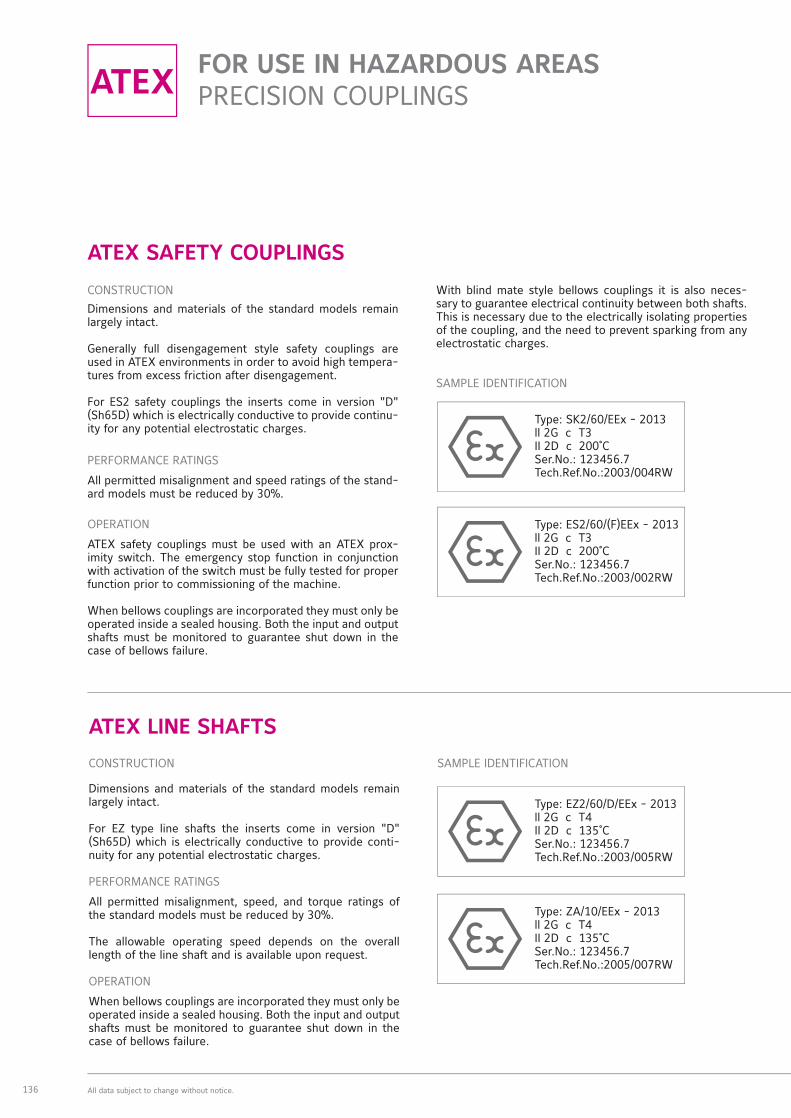
ATEX SAFETY COUPLINGS
CONSTRUCTION
Dimensions and materials of the standard models remain largely intact.
Generally full disengagement style safety couplings are used in ATEX environments in order to avoid high tempera-tures from excess friction after disengagement.
For ES2 safety couplings the inserts come in version "D" (Sh65D) which is electrically conductive to provide continu-ity for any potential electrostatic charges.
PERFORMANCE RATINGS
All permitted misalignment and speed ratings of the stand-ard models must be reduced by 30%.
OPERATION
ATEX safety couplings must be used with an ATEX prox-imity switch. The emergency stop function in conjunction with activation of the switch must be fully tested for proper function prior to commissioning of the machine.
When bellows couplings are incorporated they must only be operated inside a sealed housing. Both the input and output shafts must be monitored to guarantee shut down in the case of bellows failure.
With blind mate style bellows couplings it is also neces-sary to guarantee electrical continuity between both shafts. This is necessary due to the electrically isolating properties of the coupling, and the need to prevent sparking from any electrostatic charges.
SAMPLE IDENTIFICATION
Type: SK2/60/EEx - 2013ll 2G c T3II 2D c 200˚CSer.No.: 123456.7Tech.Ref.No.:2003/004RW
ATEX LINE SHAFTS
CONSTRUCTION
Dimensions and materials of the standard models remain largely intact.
For EZ type line shafts the inserts come in version "D" (Sh65D) which is electrically conductive to provide conti-nuity for any potential electrostatic charges.
PERFORMANCE RATINGS
All permitted misalignment, speed, and torque ratings of the standard models must be reduced by 30%.
The allowable operating speed depends on the overall length of the line shaft and is available upon request.
OPERATION
When bellows couplings are incorporated they must only be operated inside a sealed housing. Both the input and output shafts must be monitored to guarantee shut down in the case of bellows failure.
SAMPLE IDENTIFICATION
Type: EZ2/60/D/EEx - 2013ll 2G c T4II 2D c 135˚CSer.No.: 123456.7Tech.Ref.No.:2003/005RW
Type: ES2/60/(F)EEx - 2013ll 2G c T3II 2D c 200˚CSer.No.: 123456.7Tech.Ref.No.:2003/002RW
Type: ZA/10/EEx - 2013ll 2G c T4II 2D c 135˚CSer.No.: 123456.7Tech.Ref.No.:2005/007RW
R+W_Produktkatalog_Aufl3_LP_Teil5_EN.indd 136 23.10.14 13:54

RW-COUPLINGS.COM
ATEX
CER
TIFI
ED
COU
PLIN
GS
MO
DEL
REIH
EN
LPM
OD
ELRE
IHEN
ZA
| E
ZM
OD
ELRE
IHEN
SK
| E
S |
SL
MO
DEL
REIH
EN
EK |
TX
MO
DEL
REIH
EN
MK
MO
DEL
REIH
EN
BK
EIN
BAU
HIN
WEI
SED
IMEN
SIO
NIE
RUN
G
137All data subject to change without notice.
Prior to deviating from any of the previous safety in-structions please contact R+W.
The use of devices and components in explosive areas is governed by the European directives 94/9/EC (for manu-facturers) and 1992/92/EC (for operators). The presented products are non-electrical equipment of category 2. All necessary documents and certifications are stored in a known location. The conformity of these products with these guidelines is established and may be declared by the manufacturer.
According to Directive 94/9/EC, delivery of an ATEX cou-pling requires the inclusion of special installation and op-erating instructions along with the EC declaration of con-formity issued by the manufacturer. All necessary values for installation, operation and removal are included.
All statements made about ATEX conforming products are based on our present knowledge and experience. R+W re-serves the right to change technical specifications.
ATEX DISC PACK COUPLINGS
CONSTRUCTION
Dimensions and materials of the standard models remain largely intact.
PERFORMANCE RATINGS
All permitted misalignment, speed, and torque ratings of the standard models must be reduced by 30%.
OPERATION
Both the input and output shafts must be monitored to guarantee shut down in the case of disc pack failure.
SAMPLE IDENTIFICATION
Type: LP2/300/EEx - 2013ll 2G c T4II 2D c 135˚CSer.No.: 123456.7Tech.Ref.No.:2003/011RW
R+W_Produktkatalog_Aufl3_LP_Teil5_EN.indd 137 23.10.14 13:54

138
AUSTRALIA | ARGENTINA | BELGIUM | BOSNIA-HERZEGOVINA | BRAZIL | CHILE | CHINA | DENMARK |
ESTONIA | FINLAND | FRANCE | GREECE | UK | INDIA | INDONESIA | ISRAEL | ITALY | JAPAN | CANADA
| COLOMBIA | KOREA | CROATIA | LITHUANIA | MALAYSIA | MEXICO | MACEDONIA | MONTENEGRO |
NEW ZEALAND | NETHERLANDS | NORWAY | AUSTRIA | PERU | PHILIPPINES | POLAND | PORTUGAL |
ROMANIA | RUSSIA | SAUDI ARABIA | SWEDEN | SWITZERLAND | SERBIA | SINGAPORE | SLOVAKIA |
SLOVENIA | SPAIN | SOUTH AFRICA | TAIWAN | THAILAND | CZECH REPUBLIC | TURKEY | UKRAINE |
HUNGARY | USA | UNITED ARAB EMIRATES
PERFECT CONNECTIONSWORLDWIDE.
QUALITY "MADE IN GERMANY."
RW-COUPLINGS.COM
R+W_Produktkatalog_Aufl3_LP_Teil5_EN.indd 138 23.10.14 13:54

RW-COUPLINGS.COM 139
R + W ANTRIEBSELEMENTE GMBH
Alexander-Wiegand-Strasse 8D - 63911 Klingenberg/GermanyPhone +49 9372 986 40 Fax +49 9372 986 [email protected] www.rw-kupplungen.de
R+W AMERICA
1120 Tower LaneBensenville, IL 60106USAPhone +1 630 521 9911Fax +1 630 521 [email protected]
R+W MACHINERY (SHANGHAI) CO., LTD
Dept. J, 4 Floor, No 207, Tai Gu RoadPRC Waigaoquiao Free Trade Zone(Postcode 200131)Shanghai ChinaPhone +86 21 586 829 86 Fax +86 21 586 829 95 [email protected] www.rw-china.com
R+W ITALIA S.R.I.
Via Pisa, 134I - 20099 Sesto San Giovanni (MI)Phone +39 02 262 641 63 Fax +39 02 243 085 [email protected] www.rw-italia.it
R+W SINGAPORE OFFICE
55 Market Street #10-00 Singapore 048941 Phone +65 3158 4434Fax +65 6521 [email protected] www.rw-singapore.com.sge
R+W_Produktkatalog_Aufl3_LP_Teil5_EN.indd 139 23.10.14 13:54

THE COUPLING.RW-COUPLINGS.COM
QUALITY MANAGEMENTWe are certifi ed
according to ISO 9001:2008
D-ZM-16029-01-01 Registration No. 40503432/3
The information included in this document is based on our present knowledge and experience and does not exclude the manufacturer's own substantial testing of the products. Therefore we do not guarantee protection against third party claims. The sale of our product is in accordance with our general terms and conditions.
Version: 03/2014
PHONE: +49 9372 9864-0FAX: +49 9372 [email protected]
ALEXANDER-WIEGAND-STRASSE 8D-63911 KLINGENBERGWWW.RW-KUPPLUNGEN.DE
R+W ANTRIEBSELEMENTE GMBH
R+W_Produktkatalog_Aufl3_LP_Teil5_EN.indd 140 23.10.14 13:54