Embed Size (px)
Citation preview
RV-Type Training Guide 1
RV-Type Training
Syllabi, Lesson Plans,
Techniques, Procedures and
Handling Characteristics
RV-4/6/7/8/9 Version 2.2
1 Jan 2015

RV-Type Training Guide 2
Table of Contents
PART 1: GENERAL ............................................................................................................... 15
Purpose...................................................................................................................................... 15
Tracks. ....................................................................................................................................... 15
Track Descriptions. .................................................................................................................... 16
(1) Basic Transition. .......................................................................................................... 16
(2) Advanced Transition. .................................................................................................. 16
(3) Advanced Top-Off. ...................................................................................................... 16
(4) Instructor Upgrade. .................................................................................................... 16
(5) Recurrent Training. ..................................................................................................... 17
Guidance. .................................................................................................................................. 17
Using this Guide. ....................................................................................................................... 17
Experimental Amateur-Built (EAB) Aircraft. .............................................................................. 17
Operational Risk Management. ................................................................................................ 18
Aircraft Documentation. ........................................................................................................... 19
Weight and Balance Considerations. ........................................................................................ 19
Transition Training Track(s) Objective. ..................................................................................... 19
Instructor Upgrade Track Objective. ......................................................................................... 20
Recurrent Training Track Objective. .......................................................................................... 20
Table 1-1: RV-Type Basic Weight and Balance Design Limits ............................................... 20
Certificate Requirements. ......................................................................................................... 20
Basic Course Experience Requirements. ................................................................................... 21
Advanced Course Experience Requirements. ........................................................................... 21
Advanced Top-Off Course Experience Requirements. .............................................................. 21
Instructor Upgrade Course Experience Requirements. ............................................................ 21
Recurrent Course Experience Requirements. ........................................................................... 22
Average Flight Duration. ........................................................................................................... 22
Training Days. ............................................................................................................................ 22
Continuity of Training ................................................................................................................ 23
Proficiency Flights. .................................................................................................................... 23
Incomplete Flights. .................................................................................................................... 23
Testing. ...................................................................................................................................... 23
Use of Chase Aircraft. ................................................................................................................ 23
Spin Training. ............................................................................................................................. 23
Use of Parachutes. .................................................................................................................... 24
Training Documentation ........................................................................................................... 24
RV-Type Training Guide 3
(1) Grade Books. ............................................................................................................... 24
(2) Grade Sheets............................................................................................................... 24
(3) Log Book Endorsement. .............................................................................................. 24
Grading. ..................................................................................................................................... 25
Table 1-2: Grading Criteria.................................................................................................... 25
Flight Element Objectives/Standards of Behavior. ................................................................... 25
Table 1-3: Objectives/Standards of Behavior for Individual Flight Elements For Upgrading
Pilots in the Basic Transition, Advanced Transition, Advanced Top-Off and Recurrent Tracks
............................................................................................................................................... 25
GROUND OPERATIONS ...................................................................................................... 25
TAKEOFF ............................................................................................................................. 29
BASIC AIRCRAFT CONTROL................................................................................................. 30
SLOW FLIGHT AND STALLS ................................................................................................. 31
UNUSUAL ATTITUDES......................................................................................................... 33
CONFIDENCE MANEUVERS (Advanced Tracks) .................................................................. 33
ADVANCED HANDLING (Advanced Tracks) ........................................................................ 35
PATTERN AND LANDING .................................................................................................... 38
AFTER LANDING ................................................................................................................. 40
AIRMANSHIP ...................................................................................................................... 40
Table 1-4: Objectives/Standards of Behavior for Individual Flight Elements For Instructor
Upgrade ................................................................................................................................. 41
GROUND OPERATIONS ...................................................................................................... 41
TAKEOFF ............................................................................................................................. 45
BASIC AIRCRAFT CONTROL................................................................................................. 46
SLOW FLIGHT AND STALLS ................................................................................................. 48
UNUSUAL ATTITUDES......................................................................................................... 49
CONFIDENCE MANEUVERS ................................................................................................ 50
ADVANCED HANDLING ...................................................................................................... 52
PATTERN AND LANDING .................................................................................................... 56
AFTER LANDING ................................................................................................................. 58
AIRMANSHIP ...................................................................................................................... 59
INSTRUCTIONAL ABILITY .................................................................................................... 59
Situational Emergency Procedures Training (SEPT). ................................................................. 60
Course Completion Standards. .................................................................................................. 60
RV-Type Fuel Considerations .................................................................................................... 62
TRAINING RULES ................................................................................................................. 63
Weather ..................................................................................................................................... 63

RV-Type Training Guide 4
Deep Stalls, Spins and Confidence Maneuvers ......................................................................... 63
Takeoff and Landing .................................................................................................................. 63
Area ........................................................................................................................................... 64
Advanced Handling Maneuvers ................................................................................................ 64
Prohibited Maneuvers ............................................................................................................... 65
Out-of-Control ........................................................................................................................... 65
Pattern Operations .................................................................................................................... 65
Fuel ............................................................................................................................................ 65
Equipment ................................................................................................................................. 66
Minimum Bail-out Altitude ....................................................................................................... 66
Human Factors .......................................................................................................................... 66
BASIC/ADVANCED TRACK FLOW .......................................................................................... 67
INSTRUCTOR UPGRADE TRACK FLOW .................................................................................. 68
ADVANCED TOP-OFF TRACK FLOW ....................................................................................... 69
RECURRENT TRAINING TRACK FLOW .................................................................................... 70
PART 2: LESSON PLANS AND BRIEFING GUIDES.................................................................... 71
OPERATIONAL RISK MANAGMENT ....................................................................................... 71
BLOCK 1: Basic Transition/Advanced Transition/Instructor Upgrade .................................... 78
Ground 1: RV-Type Aerodynamics (.75 Hours) ........................................................................ 78
TR/ATR-1: Basic/Advanced Transition Flight 1 (1.25 Hour Flight + .75 Hour Brief + .5 Hour
Debrief) ...................................................................................................................................... 88
IPUG-1: Instructor Upgrade Flight 1 (1.25 Hour Flight + .75 Hour Brief + .5 Hour Debrief +
Instructional Critique) ............................................................................................................... 88
SEPT 1: Ground and Takeoff Emergency Procedures (.75 Hours) ............................................ 92
Emergency Procedures (EP) Basics ........................................................................................ 92
Block 2: Basic Transition/Advanced Transition/Instructor Upgrade ..................................... 93
Ground Lesson 2: RV-Type Performance (.75 Hours) .............................................................. 93
Figure 2-1: AC90-89A Minimum Recommended Runway Length Chart ....................... 94
TR/ATR-2: Basic/Advanced Transition Flight 2 (1.25 Hour Flight + .75 Hour Brief + .5 Hour
Debrief) ...................................................................................................................................... 98
IPUG-2: Instructor Upgrade Flight 2 (1.25 Hour Flight + .75 Hour Brief + .5 Hour Debrief +
Instructional Critique) ............................................................................................................... 98
RV-Type Training Guide 5
SEPT 2: In-Flight Emergency Procedures (.75 Hours) ............................................................. 102
Block 3: Basic Transition/Advanced Transition/Instructor Upgrade ................................... 103
Ground Lesson 3: RV-Type Weight and Balance (.75 Hours) ................................................. 103
Table 2-1: RV-Type Basic Weight and Balance Design Limits ............................................. 103
Table 2-2: RV-Type Useful Load with Full Fuel ................................................................... 104
Blindfold Cockpit Check (.25 Hours) ........................................................................................ 107
TR/ATR-3: Basic/Advanced Transition Flight 3 (1.25 Hour Flight + .75 Hour Brief + .5 Hour
Debrief) .................................................................................................................................... 108
IPUG-3: Instructor Upgrade Flight 3 (1.25 Hour Flight + .75 Hour Brief + .5 Hour Debrief +
Instructional Critique) ............................................................................................................. 108
SEPT 3: Landing Emergency Procedures (.75 Hours) ............................................................. 111
Block 4: Basic Transition/Advanced Transition/Instructor Upgrade ................................... 112
Ground Lesson 4: EAB Airworthiness Determination (.75 Hours) ......................................... 112
TR/ATR-4: Basic/Advanced Transition Flight 4 (1.25 Hour Flight + .75 Hour Brief + .5 Hour
Debrief) .................................................................................................................................... 115
IPUG-4: Instructor Upgrade Flight 4 (1.25 Hour Flight + .75 Hour Brief + .5 Hour Debrief +
Instructional Critique) ............................................................................................................. 115
Block 1: Advanced Top-Off ................................................................................................ 119
Risk Management Review: Human Error (0.5 Hours) ............................................................. 119
Ground 1: RV-Type Handling (.75 Hours) ............................................................................... 122
Table 2-3: RV-Type Aerobatic Limits ................................................................................... 123
ATO-1: Advanced Top-Off Flight 1 (1.0 Hour Flight + .75 Hour Brief + .5 Hour Debrief) ....... 131
Block 2: Advanced Top-Off ................................................................................................ 134
Ground Lesson 2: RV-Type Handling (.75 Hours) ................................................................... 134
ATO-2: Advanced Top-Off Flight 2 (1.0 Hour Flight + .75 Hour Brief + .5 Hour Debrief) ....... 138
Block 1: Recurrent ............................................................................................................ 141
Safety and Risk Management Review (0.5 Hours) .................................................................. 141
Ground Lesson: Regulatory Review (.5 Hours) / Tailored Instruction (.5 Hours) .................. 146
RECUR-1: Flight (1.0 Hour Flight + .5 Hour Brief + .5 Hour Debrief) ...................................... 150
WRITTEN EXAM AND REVIEW ............................................................................................ 154
PART 3: TECHNIQUES, PROCEDURES AND HANDLING CHARACTERISTICS ........................... 167
TECHNIQUES, PROCEDURES, FLOWS AND HOOKS .............................................................. 167

RV-Type Training Guide 6
Technique vs. Procedure ......................................................................................................... 167
Flows ........................................................................................................................................ 170
Hooks ....................................................................................................................................... 171
Summary ................................................................................................................................. 171
EMERGENCY EGRESS TRAINING ......................................................................................... 172
Emergency Ground Egress ...................................................................................................... 172
Parachute Pre-flight Inspection............................................................................................... 173
Determining Minimum Bail-out Altitude ................................................................................ 173
Use of an appropriate maneuvering floor. .......................................................................... 173
Out-of-Control Bailout. ........................................................................................................ 174
Controlled bail-out............................................................................................................... 176
Parachute landing considerations. ...................................................................................... 176
AIRWORTHINESS DETERMINATION AND PRE-FLIGHT INSPECTION ...................................... 176
Airworthiness Determination .................................................................................................. 176
Pre-Flight Inspection ............................................................................................................... 177
Interior Pre-flight. ................................................................................................................ 177
Exterior Pre-flight. ............................................................................................................... 178
NORMAL PROCEDURES ...................................................................................................... 182
GROUND OPERATIONS ...................................................................................................... 182
PASSENGER BRIEFING ............................................................................................................. 182
SOLO FLIGHT ............................................................................................................................ 183
BEFORE START ......................................................................................................................... 183
START ....................................................................................................................................... 185
Cold Weather Considerations. ............................................................................................. 185
Starting Carbureted Engines. ............................................................................................... 186
Starting Fuel Injected Engines. ............................................................................................ 187
Cold Start.......................................................................................................................... 187
Hot Start. .......................................................................................................................... 187
Flooding. .............................................................................................................................. 188
AFTER START ........................................................................................................................... 188
ENGINE GROUND OPERATION ................................................................................................ 189
TAXIING ................................................................................................................................... 190
Tail Wheel Steering. ............................................................................................................. 191
Nose Wheel Steering. .......................................................................................................... 191
Taxi Speed Control. .............................................................................................................. 191

RV-Type Training Guide 7
Landing Gear Rigging. .......................................................................................................... 191
Design Eye Height. ............................................................................................................... 192
Cockpit Ventilation and De-fogging. .................................................................................... 192
BEFORE TAKEOFF ..................................................................................................................... 193
Typical Lycoming Installation, Engine Operation on the Ground. ....................................... 195
High Density Altitude Takeoff. ............................................................................................. 195
Typical Lycoming Installation, Conventional Magneto Ignition Source. ............................. 196
Excessive RPM Drop, Smooth Engine during Magneto Check. ........................................ 196
Rough Engine during Magneto Check (Oil Fouled Spark Plug). ....................................... 196
Monitoring EGT during Magneto Check. ......................................................................... 197
TAKEOFF .................................................................................................................................. 198
Cross-wind Takeoff .............................................................................................................. 200
Tail Wheel Considerations. .............................................................................................. 200
Short-field Takeoff ............................................................................................................... 201
Soft-field Takeoff ................................................................................................................. 201
CLIMB ...................................................................................................................................... 202
Typical Lycoming Installation, Engine Operation during Climb ........................................... 203
CRUISE ..................................................................................................................................... 204
Typical Lycoming Installation, Engine Operation during Cruise .......................................... 205
EGT ................................................................................................................................... 205
CHT ................................................................................................................................... 205
Cold Weather Operations. ................................................................................................... 205
Power Setting. ..................................................................................................................... 205
Fuel Flow .............................................................................................................................. 206
Leaning/Mixture Control. .................................................................................................... 206
Best Power Leaning .......................................................................................................... 207
Peak EGT .......................................................................................................................... 207
Lean-of-Peak .................................................................................................................... 207
Table 3-1: Mixture Adjustment Temperature Range ......................................................... 207
Figure 3-1. Typical Lycoming Installation: Effect of leaning on CHT, EGT, power and
specific fuel consumption at constant engine RPM and manifold pressure. The red
dashed area is peak EGT to 50o rich-of-peak (ROP). Operation in this area should be
avoided. ........................................................................................................................ 209
DESCENT .................................................................................................................................. 210
LANDING PATTERN .................................................................................................................. 211
Figure 3-2. Normal Landing Pattern ............................................................................ 212
LANDING .................................................................................................................................. 212
Common errors. ................................................................................................................... 214

RV-Type Training Guide 8
Wheel Landing (Tail Wheel Equipped Airplanes). ............................................................... 215
Tail-Low Wheel Landing (Tail Wheel Equipped Airplanes). ................................................. 216
Figure 3-3: Example Stabilized Approach Criteria ....................................................... 217
Short-Field Approach and Landing .......................................................................................... 217
Cross-wind Approach and Landing .......................................................................................... 218
Maximum Demonstrated Cross-wind. ................................................................................ 218
Base Turn Adjustment. ........................................................................................................ 218
Crosswind Techniques. ........................................................................................................ 218
Tail Wheel Considerations. .................................................................................................. 219
High Gross Weight Landing ..................................................................................................... 220
GO-AROUND ............................................................................................................................ 220
AFTER LANDING ....................................................................................................................... 221
SHUT DOWN ............................................................................................................................ 221
TAKEOFF AND LANDING AT HIGH ELEVATION AIRPORTS ....................................................... 222
EMERGENCY PROCEDURES ................................................................................................ 224
GENERAL EMERGENCY CONSIDERATIONS .............................................................................. 224
GROUND OPERATION EMERGENCIES ................................................................................. 227
EMERGENCY GROUND EGRESS ............................................................................................... 227
NO OIL PRESSURE AFTER START .............................................................................................. 228
INDUCTION FIRE DURING START ............................................................................................. 228
Carburetor Temperature Considerations ............................................................................ 229
BRAKE MALFUNCTION............................................................................................................. 229
Brake Fire. ............................................................................................................................ 230
FLOODED ENGINE DURING START .......................................................................................... 231
FIRE DURING GROUND OPERATIONS ...................................................................................... 231
TAILWHEEL EQUIPPED AIRPLANES: LOSS OF DIRECTIONAL CONTROL (GROUND LOOP) ...... 232
TAKEOFF EMERGENCIES ..................................................................................................... 233
LOSS OF DIRECTIONAL CONTROL ............................................................................................ 233
REJECTED TAKEOFF/TAKEOFF ABORT ..................................................................................... 233
ENGINE FAILURE/MALFUNCTION DURING OR IMMEDIATELY AFTER TAKEOFF ..................... 234
Power Loss during Takeoff Roll ........................................................................................... 235
Power Loss Immediately After Lift-off ................................................................................. 235
On-field Landing Considerations ...................................................................................... 235
Power Loss at Low Altitude ................................................................................................. 236
Off-field Landing Considerations ..................................................................................... 236
RV-Type Training Guide 9
IN-FLIGHT EMERGENCIES ................................................................................................... 238
ELECTRICAL MALFUNCTION .................................................................................................... 238
Low Amperage Condition .................................................................................................... 238
High Amperage Condition ................................................................................................... 239
ELECTRICAL FIRE ...................................................................................................................... 240
OIL SYSTEM MALFUNCTION .................................................................................................... 241
ENGINE MALFUNCTION ........................................................................................................... 242
Engine Failure / Loss of Power ............................................................................................ 243
Engine Fire ............................................................................................................................... 243
PITOT/STATIC MALFUNCTIONS ............................................................................................... 245
Indication of Pitot Blockage. ................................................................................................ 245
Table 3-2: Example Pitch/Power Settings ........................................................................... 246
Indication of Static Blockage. .............................................................................................. 246
CONTROLLABILITY CHECK ........................................................................................................ 247
CANOPY UNITENTIONALLY OPEN DURING FLIGHT ................................................................. 247
CANOPY LOSS DURING FLIGHT ................................................................................................ 248
COCKPIT VENTILATION/HEAT MALFUNCTION ........................................................................ 248
Elevated Carbon Monoxide Level. ....................................................................................... 249
FUEL ODOR IN THE COCKPIT ................................................................................................... 249
FUEL LEAK ................................................................................................................................ 250
FUEL TRANSFER MALFUNCTION ............................................................................................. 251
ADVANCED INSTRUMENTATION MALFUNCTION ................................................................... 252
FLIGHT CONTROL MALFUNCTION ........................................................................................... 252
TRIM MALFUNCTION ............................................................................................................... 253
FLAP MALFUNCTION ............................................................................................................... 253
GLIDE PERFORMANCE ............................................................................................................. 254
OUT-OF-CONTROL ................................................................................................................... 257
“Idlize and Neutralize.” ........................................................................................................ 258
Other Considerations ........................................................................................................... 260
Bailout .............................................................................................................................. 260
Human Factors Considerations ........................................................................................ 260
Control Inputs .................................................................................................................. 260
Engine Operation ............................................................................................................. 260
Spins ........................................................................................................................................ 261
Figure 3-4: Spin Forces ................................................................................................ 262
Inverted Spins. ..................................................................................................................... 262
Fuel Asymmetry. .................................................................................................................. 263
Spiral Dive ................................................................................................................................ 263

RV-Type Training Guide 10
BAIL OUT .................................................................................................................................. 264
Post Bail-out......................................................................................................................... 264
PASSENGER INCAPACITATION ................................................................................................. 265
EMERGENCY DESCENT ............................................................................................................ 266
Additional Considerations ................................................................................................... 267
Airspeed ........................................................................................................................... 267
Flutter ............................................................................................................................... 267
Flutter Margin .................................................................................................................. 267
Flutter Encounter ............................................................................................................. 267
LANDING EMERGENCIES .................................................................................................... 269
LANDING WITH KNOWN FLAT MAIN TIRE............................................................................... 269
EMERGENCY LANDING PATTERN ............................................................................................ 269
Figure 3-5. Emergency Landing Pattern. ..................................................................... 273
Landing on an Unprepared Surface. .................................................................................... 273
AIRSPEED INDICATOR FAILURE ............................................................................................... 274
DITCHING ................................................................................................................................. 274
ALL WEATHER OPERATION ................................................................................................ 276
COLD WEATHER OPERATIONS................................................................................................. 276
High-volume Heater Use ..................................................................................................... 277
Carbon Monoxide Considerations ....................................................................................... 278
Induction System Icing ......................................................................................................... 279
Carburetor Icing ............................................................................................................... 279
Carburetor Heat ............................................................................................................... 280
Alternate Air Source ......................................................................................................... 281
Pitot Heat ............................................................................................................................. 281
Mixture Adjustment ............................................................................................................ 281
Airframe Icing ...................................................................................................................... 281
Pre-flight Considerations ................................................................................................. 281
In-flight Considerations .................................................................................................... 282
Tailplane Icing. .............................................................................................................. 282
Icing Considerations ......................................................................................................... 283
Cold Weather Altimeter Error .......................................................................................... 285
Table 3-3. ICAO Cold Temperature Error Table .................................................................. 286
RAIN AND SNOW ..................................................................................................................... 287
Propeller Erosion ................................................................................................................. 287
Hydroplaning ....................................................................................................................... 287
Contaminated Runway Effect on Takeoff and Landing Performance ................................. 287
RV-Type Training Guide 11
Table 3-4. Contaminated Runway Effect on Takeoff and Landing Performance ............... 288
BASIC IMC CONSIDERATIONS .................................................................................................. 288
ROUGH AIR OPERATION / TURBULENCE PENETRATION ......................................................... 289
CRUISE DESCENT ..................................................................................................................... 289
HOLDING ................................................................................................................................. 289
APPROACH ............................................................................................................................... 290
LOW-LEVEL WIND SHEAR ........................................................................................................ 290
HANDLING CHARACTERISTICS ............................................................................................ 292
STATIC MARGIN ....................................................................................................................... 292
STABILITY AND CONTROL ........................................................................................................ 293
Longitudinal Stability: .......................................................................................................... 293
Lateral (Roll) Stability:.......................................................................................................... 293
Directional (Yaw) Stability: .................................................................................................. 293
CENTER OF GRAVITY CONSIDERATIONS .................................................................................. 293
Longitudinal (Pitch) Stability. ............................................................................................... 296
Figure 3-6. Basic aircraft stability. ............................................................................... 297
Aerobatic Limits. .................................................................................................................. 297
Pitch Trim. ............................................................................................................................ 298
Directional (Yaw) Stability. .................................................................................................. 298
Lateral (Roll) Stability. .......................................................................................................... 299
STALLS...................................................................................................................................... 299
1-G Stalls. ............................................................................................................................. 299
Accelerated stalls. ................................................................................................................ 300
Post-stall behavior. .............................................................................................................. 301
Figure 3-7. Example of Bank Effect on Indicated Stall Speed (1G calibrated stall speed
is 60 MPH/53 Knots in this example). .......................................................................... 301
Cross-Control Stalls. ............................................................................................................. 301
Slip .................................................................................................................................... 301
Skid ................................................................................................................................... 302
Recovery ........................................................................................................................... 302
MANUEVERING FLIGHT ........................................................................................................... 303
Symmetric G Application/Maneuvering. ............................................................................. 303
Asymmetric G Application/Maneuvering. ........................................................................... 303
Maneuvering Speed. ............................................................................................................ 304
Design Load Limit (G Allowable). ......................................................................................... 304

RV-Type Training Guide 12
Figure 3-8: RV-7 Maneuvering Speed and G-Allowable (G Limit) vs Gross Weight.
Derived from Van’s Aircraft published performance data for RV-7/7A. All two-seat RV-
types exhibit similar relationships. .............................................................................. 305
Table 3-5. RV-Type Example Maneuvering Speeds ............................................................ 306
G Available. .......................................................................................................................... 307
Table 3-6. Example RV-4 Aerodynamic G-Available at 1375 Lbs Gross Weight ................. 307
Cockpit G. ............................................................................................................................. 307
Radial G. ............................................................................................................................... 307
Lift Vector. ........................................................................................................................... 308
Velocity Vector. ................................................................................................................... 308
Maneuvering Summary ........................................................................................................... 309
TURN PERFORMANCE ............................................................................................................. 310
Level Turns. .......................................................................................................................... 310
Figure 3-9. Bank and Airspeed Effect on Turn Radius (Level Turn) ............................. 311
Figure 3-10. Example Turn Rate/Radius Diagram for an RV-4. Instantaneous turn
performance is black and sustained turn performance is red. Turn rate (deg/sec) are
the hill shaped curves and turn radius (feet) are the valley shaped curves. Maximum
rate and minimum radius = best turn performance. ................................................... 312
Figure 3-11. Constant 3 G Vertical Turn ...................................................................... 313
Vertical Turn Performance. ................................................................................................. 313
Turn Performance Summary ................................................................................................... 314
ENERGY MANAGEMENT .......................................................................................................... 314
MAXIMUM STRUCTURAL CRUISING SPEED ............................................................................ 314
NEVER EXCEED SPEED ............................................................................................................. 315
Flutter. ................................................................................................................................. 315
ACCELLERATION CHARACTERISTICS ........................................................................................ 317
ENGINE AND PROPELLER EFFECTS .......................................................................................... 318
Figure 3-12: Propeller Effect—Spiraling Slipstream .................................................... 318
Figure 3-13: Engine Effect—P-Factor .......................................................................... 319
Figure 3-14: Propeller Effect—Gyroscopic Precession ................................................ 320
Figure 3-15: Propeller Effect—Torque ........................................................................ 320
STABILITY CHECK ..................................................................................................................... 321
Pitch Check. ......................................................................................................................... 321
Roll Check. ........................................................................................................................... 321
Yaw Check. ........................................................................................................................... 321
UNUSUAL ATTITUDES/UPSET RECOVERY ................................................................................ 322
Unload for Control Concept. ............................................................................................... 322
Nose High, Airspeed Decreasing/Low Airspeed Recovery. ................................................. 323
RV-Type Training Guide 13
Nose Low, Airspeed Increasing or High Airspeed. ............................................................... 324
Emergency Dive Recovery. .................................................................................................. 325
INTENTIONAL SPINS ................................................................................................................ 325
Intentional Spin Recovery Technique. ................................................................................. 329
CONFIDENCE MANEUVERS................................................................................................. 330
Lazy 8 ....................................................................................................................................... 331
Chandelle ................................................................................................................................. 332
Low AOA Maneuvering ........................................................................................................... 333
AOA (Ballistic) Recovery. ..................................................................................................... 335
Inverted Low AOA Recovery. ............................................................................................... 336
Low AOA Aileron Roll. .......................................................................................................... 336
Deep Stall ................................................................................................................................ 337
Incipient Spin ........................................................................................................................... 338
Cross-controlled Stall .............................................................................................................. 338
Slip. ...................................................................................................................................... 339
Skid....................................................................................................................................... 339
ANTI-G STRAINING .................................................................................................................. 340
ADVANCED HANDLING ...................................................................................................... 341
Warm-up ................................................................................................................................. 343
G Warm-up. ......................................................................................................................... 344
Acceleration Maneuver. .......................................................................................................... 344
Basic Rolls ................................................................................................................................ 345
Modified Aileron Roll. .......................................................................................................... 345
Hesitation Rolls ........................................................................................................................ 346
Loop ......................................................................................................................................... 347
Aborted Loop ........................................................................................................................... 348
Figure 3-16: Aborted Loop Exercises ........................................................................... 349
Pitch Back ................................................................................................................................ 349
Slice Back ................................................................................................................................. 349
Barrel Roll ................................................................................................................................ 350
Split-S ....................................................................................................................................... 351
Immelmann. ............................................................................................................................ 352
Cuban 8 .................................................................................................................................... 353
Cloverleaf ................................................................................................................................ 353
Hammerhead/Stall Turn .......................................................................................................... 354
Snap Roll/Flick Roll .................................................................................................................. 355
Tail Slide .................................................................................................................................. 356

RV-Type Training Guide 14
Handling Error Summary.................................................................................................... 357
APPENDIX A: PERSONAL PROFICIENCY TRAINING .............................................................. 358
Proficiency Training Concept .................................................................................................. 358
Mentor Concept ...................................................................................................................... 358
Table A-1: Example Annual Proficiency Training Program ................................................. 358
APPENDIX B: RV-4/6/7/8 ADVANCED HANDLING BRIEFING ............................................... 361
Instructor Briefing Considerations .......................................................................................... 361
RV-4/6/7/8 Advanced Handling Briefing Guide ...................................................................... 363
APPENDIX C: RV-TYPE HANDLING RULES OF THUMB ......................................................... 397
RV-Type Training Guide 15
Part 1: General
Purpose. The purpose of this Guide is to provide syllabi (including objective standards), lesson
plans and briefing guides, discussion, techniques and procedures applicable to RV-Type
transition training for upgrading pilots with or without previous experience in type. It also
supports instructor upgrade and RV-type recurrent training. Five specific tracks of instruction
are included: Basic Transition (TR); Advanced Transition (ATR); Advanced Top-Off (ATO),
Instructor Upgrade (IPUG) and Recurrent (RECUR). Not all portions of the syllabus are
applicable to all tracks. It is incumbent upon the instructor to evaluate upgrading
pilot/instructor requirements, aircraft capability and equipment, and modify the program
accordingly. This guide has been prepared from multiple sources and is designed to be used in
conjunction with the FAA Airplane Flying Handbook (FAA-H-8083-3A) and the FAA Pilot’s
Handbook of Aeronautical Knowledge (FAA-H-8083-25A), appropriate Advisory Circulars as well
as designers/builder’s information, operating limitations and weight and balance data for the
specific RV-type operated. Techniques, recommendations and suggested procedures are
provided to assist the instructor and upgrading pilot as well as providing a degree of
standardization and continuity. This manual is not designed to replace specific FAA, designer,
kit/component manufacturer or builder’s guidance. At the successful completion of transition,
upgrade or recurrent training, the pilot/instructor should be able to perform maneuvers to the
minimum standard appropriate to pilot privileges to be exercised in the operation of the RV-
type aircraft. Objective Standards of Behavior in Table 1-3 and 1-4 conform to appropriate FAA
Practical Test Standards. The most current versions of FAA publications may be obtained on-
line at www.faa.gov. Objective Standards for confidence maneuvers and advanced handling
required for syllabus completion are “practice” vs. “proficient” (See Table 1-2 for definitions)
for transition and recurrent tracks of instruction. “Proficient” is required in all tasks for
instructor upgrade. Additional training in any area may be given at any time at the discretion of
the instructor or request of the upgrading pilot/instructor. Although recommended flight
duration and course completion times are established in this syllabus, there are no maximum
time limits with the desired outcome of the upgrading pilot/instructor trained to proficiency, or
practice level, as appropriate. Additionally, transition training requirements may be established
by the insurance carrier in excess of the minimum time limits established in these syllabi.
Tracks. These syllabi are designed to support multiple tracks of instruction. They contain
information for basic transition (Basic Course); advanced transition (Advanced Course);
instructor qualification (Instructor Upgrade); advanced top-off (Top-off); and recurrent training
(Recurrent). The Basic Course is designed for upgrading pilots transitioning to RV types without
prior experience in RV type aircraft. It includes takeoff, landing, basic air work and emergency

RV-Type Training Guide 16
procedures. The Advanced Course is also designed for upgrading pilots without prior RV type
experience/qualification but includes all-attitude maneuvering. The advanced top-off is
designed for RV qualified pilots that desire all-attitude maneuvering training. Instructor
Upgrade is designed to qualify and standardize instructors to provide all tracks of transition and
recurrent training in RV-type aircraft. Recurrent training is designed to meet the requirements
for a flight review.
Track Descriptions.
(1) Basic Transition. The basic transition course consists of Operational Risk Management
(ORM)/Aircrew Decision Making (ADM) review and 4 blocks of training. Each block
consists of academics (.75 hour), situational emergency procedures training (.75 hour)
and one training flight with an average duration of 1.25 hours with .75 hours allotted for
brief, and .5 hours allotted for debrief. Each block is designed to be completed within 5-
6 hours total time, including breaks. Academics include RV type aerodynamics;
performance; weight and balance and Experimental/Amateur Built (EAB) airworthiness
determination. The basic transition course covers preflight, ground operation, takeoff,
landing, basic air work (including slow flight and stalls) and emergency procedures. It is
designed to qualify the upgrading pilot for basic, non-aerobatic operation of RV type
aircraft. For documentation purposes, Basic Transition courses are coded “TR.”
(2) Advanced Transition. The advanced transition course is structured identically to the
basic transition course, but includes confidence maneuvers and advanced handling
(aerobatics). It is designed to qualify the upgrading pilot for operation of RV type
aircraft in all areas of operation, including all-attitude flying. For documentation
purposes, Advanced Transition courses are coded “ATR.”
(3) Advanced Top-Off. The advanced top-off course is designed for upgrading pilots
already qualified in RV-type aircraft. In addition to review of basic operation and
emergency procedures, it includes confidence maneuvers and advanced handling
designed to prepare the upgrading pilot for all-attitude operation. It consists of 2 blocks
of training. Each block consists of academics (.75 hour), and one training flight with an
average duration of 1.25 hours with .75 hours allotted for brief, and .5 hours allotted for
debrief. A .5 hour Risk Management Review is included in Block 1. Each block is
designed to be completed within 4-5 hours total time, including breaks. For
documentation purposes, Advanced Top-Off courses are coded “ATO.”
(4) Instructor Upgrade. Instructor upgrade mirrors the advanced transition track, including
instruction of Operational Risk Management/Aircrew Decision Making. The upgrading
instructor will prepare, brief, conduct and debrief all training associated with
completion of the advanced qualification syllabus. An instructional critique will be

RV-Type Training Guide 17
conducted, as appropriate, throughout each block of instruction. For documentation
purposes, Instructor Upgrade is coded “IPUG.”
(5) Recurrent Training. Consists of one block of instruction that includes a safety/ORM
review, one hour of academics developed by the instructor or at the request of the pilot
receiving recurrent training and a minimum of one hour of flight training. The recurrent
training block of instruction is designed to be completed within 4 hours, including
breaks. For documentation purposes, recurrent training is coded “RECUR.”
Guidance. Applicable pilot certification and currency guidance is provided in 14 CFR Part 61.
Operational guidance is provided in 14 CFR Part 91. Current versions of these Federal Aviation
Regulations (FARs) should be consulted. Current regulations and other publications may be
obtained on-line at www.faa.gov. Additional techniques applicable to operation of aircraft may
be obtained from the Airman’s Information Manual (AIM) and the FAA Flight Training
Handbook. In some cases, this Guide is more restrictive than FARs (e.g., Training Rules,
currency requirements, etc.).
Using this Guide. This manual has been prepared using numerous sources. It is designed for
instructor use in preparing briefings and lesson plans as well as providing standardization
guidance to ensure continuity of effort. Part 1 contains a course description for each track,
objective standards, grading criteria and recommended training rules to support the different
tracks of instruction. Part 2 includes academics in the form of briefing guides and lesson plans.
Part 3 includes additional academic/background information, generic pilot guidance (in the
form of techniques and procedures that can be adapted to the different tracks of instruction
after critical review) and RV-type handling characteristics. Generic expanded checklists are
included in the NORMAL and EMERGENCY procedures section in Part 3 if specific guidance for
the RV-type to be operated for or after training is not available.
Experimental Amateur-Built (EAB) Aircraft. RV-type aircraft are designed and constructed as
an Experimental amateur-built aircraft. They are not designed or built to meet any standards
of airworthiness as with a standard certificated aircraft. 14 CFR Section 21.191(g) defines an
amateur-built aircraft as an aircraft in which the major portion of the aircraft has been
fabricated and assembled by persons who undertook the construction project solely for their
own education or recreation. RV-type aircraft do not have an FAA Form 8130-9 “Statement of
Conformity” on file with the FAA, since there is no FAA Approval data to which they conform.
The builder and/or owner of this aircraft were and are experimenters and the aircraft where
not built in permanent jigs and parts are not necessarily interchangeable with any other
aircraft. The registered owner is free make modifications as he or she wishes. EAB aircraft
must possess an unlimited duration special airworthiness certificate and operating limitations
issued by the FAA. The operating limitations are set forth under guidance prescribed in Order
RV-Type Training Guide 18
8130.2 and established to maintain compliance with 14 CFR 91.319. Maintenance and
operation of EAB aircraft must be in accordance with the operating limitations.
(1) EAB aircraft used in the conduct of RV-Type transition training must be in Phase 2
operations (i.e., initial test period complete). All maneuvers flown in the conduct of
training must have been previously tested under similar load conditions and in
accordance with Operating Limitations issued for that airplane.
(2) EAB aircraft may not be operated for hire unless an appropriate Letter of Deviation
Authority (LODA) has been issued by the appropriate FAA Flight Standards District
Office.
(3) Instructors may receive remuneration for conduct of training in an upgrading pilot’s
aircraft.
Operational Risk Management. A continuing cycle of risk assessment, aircrew decision making,
and applying control measures to: a) avoid risk; b) mitigate risk or c) consciously accept risk.
The core principles to successful risk management are to anticipate/manage risk by planning
(i.e., thinking); accept no unnecessary risk; and consciously accept risk when the benefits
outweigh the potential cost. Risk management is a continual process and must be taught
and/or emphasized to upgrading pilots. 80% of all mishaps involve human factors, with the
majority of these mishaps occurring during takeoff and landing phase of flight. For
Experimental/Amateur Built (EAB) types, maneuvering flight carries increased risk. The initial
period of transition to operation of EAB types (the first 5-8 hours of initial operating
experience) has also proven to be a moderate to high risk phase of operation as well. To
manage risk during the conduct of training, and establish a basic framework to assist upgrading
pilot decision making, a set of recommended training rules is contained in this Guide. These
rules may be more restrictive than guidance contained in the FARs or aircraft Operating
Limitations.
(1) Upgrading pilots should complete the King School’s “Practical Risk Management for
Pilots” course prior to the conduct of training. The appropriate course completion
certificate shall be maintained in the upgrading pilot’s grade book. This course may
be obtained on-line at www.kingschools.com or by calling (800) 854-1001.
Note
LODA restrictions may prohibit the conduct of some tracks of training as included in these syllabi.
RV-Type Training Guide 19
Aircraft Documentation. Documentation must be reviewed and verified by the instructor prior
to utilizing an RV-type aircraft for training purposes. The airworthiness certificate and
operating limitations must be maintained aboard the aircraft during operation. The
airworthiness certificate shall be displayed in a manner so that it is visible to either the
passengers or crew. Additionally, a current registration form and weight and balance data shall
be maintained on board. The registration form must not be expired and have a current address
on it for the registered owner(s). Documentation that the aircraft has completed appropriate
flight test requirements is maintained in the airframe logbook. The operating limitations,
weight and balance data and airframe logbook must be reviewed prior to flight.
Weight and Balance Considerations. Accurate weight and balance data must be available for
the airplane operated during the conduct of training. Like all light planes, RV-types are
sensitive to loading and accurate assessment of performance and handling characteristics
cannot be achieved without current weight and balance data. One of the primary limitations
likely to be encountered is G-allowable or the ability to perform advanced maneuvers (if
appropriate) during the conduct of training. Longitudinal stick force gradient and post-stall
handling characteristics are highly dependent upon CG location. Depending on the airplane and
crew weight, it may not be practical to carry full fuel for the conduct of dual instruction.
Transition Training Track(s) Objective. The upgrading pilot will obtain the aeronautical skill and
knowledge necessary to operate an RV-Type airplane commensurate with private pilot
certification standards. If flown (as appropriate), advanced maneuvers need only be
demonstrated to a safe (“practice”) level for course completion. See Table 1-3.
Note
At the instructor’s discretion, appropriate airline, FAA/Industry-sanctioned or military training in risk management/aircrew decision making may be substituted for this requirement.
Note
Maximum allowable gross weight is contained in the Operating Limitations specific to the airplane utilized for training. However, for the conduct of these tracks of instruction, designer’s weight and balance limits should be utilized unless the Operating Limitations are more restrictive. Designer’s limits are contained in Table 1-1.

RV-Type Training Guide 20
Instructor Upgrade Track Objective. The upgrading instructor will obtain the high level of
aeronautical skill and knowledge necessary to instruct in RV-type aircraft (including briefing, in-
flight instruction and flight reconstruction/debriefing). All flying and instructional tasks will be
demonstrated to proficiency level (commensurate with commercial pilot certification
standards) for course completion. See Table 1-4.
Recurrent Training Track Objective. Completion of a flight review IAW 14 CFR 61.65, as
amended.
Table 1-1: RV-Type Basic Weight and Balance Design Limits
Type Max Allowable Gross Weight
Max Aerobatic
Gross Weight
Forward CG Limit2
Aerobatic CG Limit2
Aft CG Limit2
RV-4 1500 LBS 1375 LBS 68.7 75.9 77.4
RV-6 1600 LBS 1375 LBS 68.7 75.3 76.8
RV-6A 1650 LBS 1375 LBS 68.7 75.3 76.8
RV-7 1800 LBS 1600 LBS 78.7 84.5 86.82
RV-7A 1800 LBS 1600 LBS 78.7 84.5 86.82
RV-8* 1800 LBS 1600 LBS* 78.7 85.3 86.82
RV-8A* 1800 LBS 1600 LBS* 78.7 85.3 86.82
Max Utility Gross Weight
Utility CG Limit2
RV-9/A1 1750 LBS 1600 LBS 77.95 82.72 84.84 *1550 LBS if not equipped with the -1 wing. 1Not designed for aerobatic flight
2Inches aft of datum. Datum for RV-4/6(A) is 60” ahead of the leading edge of the wing, and 70” ahead of the LE
for RV-7(A)/8(A)/9(A).
Certificate Requirements. Upgrading pilots will possess a minimum of a private pilot’s
certificate with airplane, single-engine, land ratings and a valid 3rd Class Medical Certificate. For
Instructor upgrade, the upgrading instructor will possess a minimum of a commercial pilot’s
certificate with instrument airplane, single-engine, land ratings, and current Flight Instructor’s
Certificate, or an expired Flight Instructor’s Certificate, or a Ground Instructor Certificate, or a
valid teaching certificate issued by a recognized licensing organization, or a valid/prior military
instructor rating and a valid 3nd Class medical certificate.
Note
A valid medical certificate is required if the upgrading pilot/instructor is operating as pilot-in-command.

RV-Type Training Guide 21
Basic Course Experience Requirements. Upgrading pilots will have completed a Flight Review
in accordance with 14 CFR 61.57, or other qualifying flight check/examination within the
preceding 24 months prior to the beginning of transition training. For transition training in tail
wheel equipped RV-type aircraft, the upgrading pilot will possess a tail wheel endorsement or
have tail wheel experience logged prior to 15 April, 1991. Upgrading pilots will have logged a
minimum of 3 hours of pilot-in-command time in an airplane in the 30 days prior to the
beginning of training. Pilots upgrading to tail wheel equipped RV-types will have completed a
minimum of 3 takeoffs and full stop landings in a tail wheel equipped aircraft within the 30 days
preceding the beginning of transition training. Pilots upgrading to a nose wheel equipped RV-
type aircraft will have completed a minimum of 3 takeoffs and landings in a nose wheel
equipped aircraft within the 60 days preceding the beginning of transition training. Appropriate
log book/flight record entries documenting experience must be presented prior to the conduct
of training.
Advanced Course Experience Requirements. In addition to the requirements in the paragraph
above (Basic Course Experience Requirements), pilots upgrading to tail wheel equipped RV-
types will have completed a minimum of 10 takeoffs and full stop landings in a tail wheel
equipped aircraft with 150 or more horsepower within the 30 days preceding the beginning of
transition training. Pilots upgrading to a nose wheel equipped RV-type aircraft will have
completed a minimum of 3 takeoffs and landings in a nose wheel equipped aircraft with 150 or
more horse power within the 30 days preceding the beginning of transition training. Upgrading
pilots will have completed an aircraft handling sortie within the preceding 30 days prior to the
start of training in a single-engine, propeller driven aircraft with a MGTOW of less than 4000 lbs
that includes: at least one short-field takeoff and landing to a full stop; at least one soft-field
takeoff and landing to a full stop; power off stalls; power on stalls and slow flight. Upgrading
pilots completing the advanced maneuvers portion of this syllabus will have prior aerobatic
experience. Appropriate log book/flight record entries documenting experience must be
presented prior to the conduct of training.
Advanced Top-Off Course Experience Requirements. Prior qualification in a RV type(s). 3
takeoffs and landings and 3 hours of pilot in command time in a RV type(s) within 30 days
preceding the beginning of training. Appropriate log book/flight record entries documenting
experience must be presented prior to the conduct of training.
Instructor Upgrade Course Experience Requirements. Prior qualification in a RV type(s): For
initial instructor upgrade (i.e., not a previously qualified instructor), the upgrading instructor
will have a minimum of 300 hours of pilot-in-command time logged in RV-type(s) aircraft. For
upgrading instructors with previous instructor qualification in other aircraft or possessing a
Certified Flight Instructor certificate, a minimum of 100 hours of pilot-in-command time in RV
RV-Type Training Guide 22
type(s) aircraft is required. 3 takeoffs and landings and 3 hours of pilot in command time in a
RV type(s) aircraft within 30 days preceding the beginning of training. Appropriate log
book/flight record entries documenting experience must be presented prior to the conduct of
training.
Recurrent Course Experience Requirements. Prior qualification in an RV type(s).
Average Flight Duration. The basic and advanced transition courses are designed for four
flights of 1.25 hours average duration. The advanced top-off course is designed for two flights
of 1.25 hours average duration. The instructor upgrade course uses the flow of the advanced
transition course and is designed for four flights of 1.25 hours average duration. The recurrent
course is designed for one flight of a minimum of 1.0 hours average duration. The instructor
may adjust flight duration to accommodate local constraints and ensure completion of all
required training events. Flights may be broken up into shorter segments and flight elements
may be deferred at instructor discretion. A minimum of 5 hours of in-flight instruction is
required for course completion of Basic, Advanced Transition and Instructor Upgrade tracks, a
minimum of 2.5 hours of in-flight instruction is required for Advanced Top-Off, and a minimum
of 1.0 hours of in-flight instruction is required for Reccurent training.
Training Days. The basic, advanced transition and instructor upgrade courses are designed to
be completed in four training days, with one block of instruction completed per training day.
The advanced top-off course is designed to be completed in two training days, and the
recurrent course is designed to be completed in one training day. At the instructor’s discretion,
up to two blocks may be completed in one day.
Note
Formal risk management training must be complete prior to beginning Block 1 training in the Basic, Advanced Transition and Instructor Upgrade tracks. If this student has not completed risk management training, an additional half training day is required prior to beginning Block 1 instruction.
Note
Experience requirements for any track of instruction may be modified at the instructor’s discretion. They have been established to provide a reasonable expectation that the appropriate track can be completed within time allotted. Variation in experience and currency is to be expected and will affect the amount of time required to complete training.
RV-Type Training Guide 23
Continuity of Training. One of the most important facets of effective training is ensuring
adequate continuity. No more than seven calendar days should elapse between training flights.
If a break exceeding seven days occurs, the previous flight should be re-flown for proficiency
prior to moving on to the next flight in the track. If more than two days has elapsed between
flights, the instructor should expect that the upgrading pilot may require additional review.
Briefing, flight tasks and flight duration may need to be adjusted to accommodate.
Proficiency Flights. Additional proficiency (practice) flights may be added to the syllabus at the
instructor’s discretion. Grade sheets will be annotated with a “P” to indicate a proficiency flight
(e.g., TR-3P). A proficiency flight may be generated due to break in training, upgrading pilot
non-progression, upgrading pilot confidence/request, or for any reason at the instructor’s
discretion.
Incomplete Flights. If a flight is non-effective for weather, mechanical breakdown, etc., it will
be considered incomplete and an additional flight will be generated to complete task
requirements. The grade sheet should clearly state the flight is incomplete and an overall flight
grade should not be assigned for the incomplete portion (individual elements/tasks that were
completed should be graded, however).
Testing. The upgrading pilot/instructor will complete open-book written testing when required
by the syllabus track. The minimum passing score for a written examination is 70%, and all
examinations will be de-briefed with an instructor and corrected to 100%. In the event the
minimum passing score is not achieved, the upgrading pilot will continue to re-take the test
until a minimum passing grade is achieved. See WRITTEN EXAMINATION AND REVIEW.
Use of Chase Aircraft. RV-type aircraft are load-sensitive and not all are fitted with dual flight
controls. In some cases (e.g., RV-4), lack of RCP load capacity and dual controls may make it
impractical to conduct training in a specific aircraft. It may, however, be practical to conduct
two-ship training if an appropriately qualified instructor and equivalent airplane are available
for use. Chase flying is an instructor pilot using a suitable equivalent airplane to accompany a
solo upgrading pilot and supervise in-flight training. The instructor pilot must be familiar with
this type of formation flying and flight instruction technique prior to conducting chase
operations. For the purpose of these syllabi, flying with a chase aircraft is not considered
formation flying, and the upgrading pilot need not be proficient in formation operations. The
chase aircraft/instructor pilot maintains responsibility for ensuring inter-flight deconfliction at
all times.
Spin Training. Spin training will be conducted in accordance with AC61-67C, as amended. Spin
training, when conducted, will be limited to incipient spin phase only. The incipient phase is
defined as the portion of the spin from the time the airplane stalls and rotation starts until the

RV-Type Training Guide 24
spin becomes fully developed. When conducted for the purpose of these tracks of instruction,
spin training will be limited to incipient spins of one turn duration, or less.
Use of Parachutes. Appropriately inspected parachutes will be worn any time planned
maneuvering will exceed ± 30o of pitch or ± 60o of bank. Parachute weight must be factored
into weight and balance calculations. A weight of 14 lbs per parachute will be used for weight
and balance purposes if exact weight of parachute is not known.
Training Documentation. Individual upgrading pilot/instructor grade books should be prepared
to document transition training. Grade books should contain a training log, unaccomplished
task log and individual grade sheets for each flight.
(1) Grade Books. Completed original grade books are the property of the flight
instructor and will be retained for record. A copy will be provided to the upgrading
pilot at the completion of training at the upgrading pilot’s request.
(2) Grade Sheets. The instructor will prepare a grade sheet for each training flight
flown. Individual maneuver elements/tasks will be objectively graded, and when
proficiency is required, a “P” will be pre-printed at the appropriate level to aid the
instructor in making a determination. Objective grading criteria, flight completion
standards and specific maneuvering limitations will be printed on the back of each
grade sheet. An overall subjective grade will be assigned for each flight.
(3) Log Book Endorsement. The instructor will annotate and endorse the upgrading
pilot’s log, as appropriate.
Note
In accordance with AC61-67C Paragraph 301(b), parachutes are not required for spin training.
Note
Individual maneuvers and flight elements may be graded below required proficiency level and the upgrading pilot/instructor may progress to the next flight at the instructor’s discretion, however all required maneuvers will be complete to the appropriate grade level prior to course completion. Flight elements graded below standard and unaccomplished tasks should be recorded and tracked in the unaccomplished task log in the student grade book.

RV-Type Training Guide 25
Grading. Individual flight elements and maneuvers will be assigned a numeric grade in
accordance with the standards in Table 1-2. Specific criteria are established for individual
elements to allow for objective grading. An overall (average) numeric grade using the same
scale should be assigned to the flight by the instructor. The instructor will also make a
subjective progress assessment at the conclusion of each flight. Progress assessment levels are
BELOW AVERAGE; AVERAGE; or ABOVE AVERAGE.
Table 1-2: Grading Criteria
UNKOWN Performance not observed or element not performed
DANGEROUS Performance unsafe (requires overall grade of 0)
0 Performance indicates lack of ability or knowledge
1 Performance is safe, but indicates limited proficiency, makes errors of omission or commission. Minimum grade required to meet syllabus definition of “practice.”
2 Performance is essentially correct. Recognizes and corrects errors. Minimum grade required to meet syllabus definition of “proficient.”
3 Performance is correct, efficient, skillful and without hesitation
4 Performance reflects unusually high degree of ability
Flight Element Objectives/Standards of Behavior. Standards for proficiency of individual flight
elements are listed in Tables 1-3 and 1-4. Table 1-3 is to be used for upgrading pilots
completing the Basic, Advanced, Advanced Top-Off or Recurrent track(s). Table 1-4 is to be
used for instructor upgrade track.
Table 1-3: Objectives/Standards of Behavior for Individual Flight Elements For Upgrading Pilots in the Basic Transition, Advanced Transition, Advanced Top-Off and Recurrent Tracks
Element Min Grade
Req
Objectives/Standards of Behavior
GROUND OPERATIONS
Weather / NOTAM Information
2 -Able to obtain sufficient information from an FAA approved source to make Go / No-Go decision for conduct of flight -Understands airspace requirements/limitations and temporary flight restrictions
TOLD (Takeoff and Landing Data)
2 -Able to compute or estimate takeoff and landing performance; able to determine runway requirements for safe operation under existing conditions; able to compute decision points -Understands factors affecting performance and able to apply appropriate takeoff and landing safety factors -Understands Koch Chart for density altitude effects
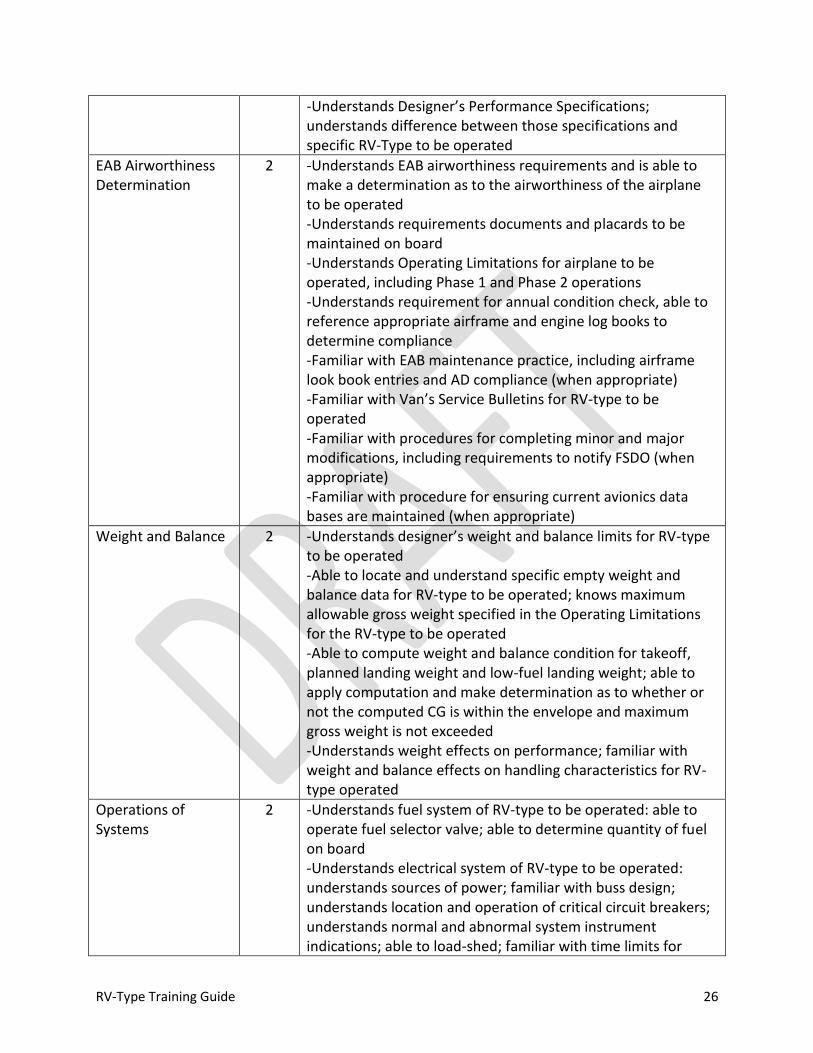
RV-Type Training Guide 26
-Understands Designer’s Performance Specifications; understands difference between those specifications and specific RV-Type to be operated
EAB Airworthiness Determination
2 -Understands EAB airworthiness requirements and is able to make a determination as to the airworthiness of the airplane to be operated -Understands requirements documents and placards to be maintained on board -Understands Operating Limitations for airplane to be operated, including Phase 1 and Phase 2 operations -Understands requirement for annual condition check, able to reference appropriate airframe and engine log books to determine compliance -Familiar with EAB maintenance practice, including airframe look book entries and AD compliance (when appropriate) -Familiar with Van’s Service Bulletins for RV-type to be operated -Familiar with procedures for completing minor and major modifications, including requirements to notify FSDO (when appropriate) -Familiar with procedure for ensuring current avionics data bases are maintained (when appropriate)
Weight and Balance 2 -Understands designer’s weight and balance limits for RV-type to be operated -Able to locate and understand specific empty weight and balance data for RV-type to be operated; knows maximum allowable gross weight specified in the Operating Limitations for the RV-type to be operated -Able to compute weight and balance condition for takeoff, planned landing weight and low-fuel landing weight; able to apply computation and make determination as to whether or not the computed CG is within the envelope and maximum gross weight is not exceeded -Understands weight effects on performance; familiar with weight and balance effects on handling characteristics for RV-type operated
Operations of Systems
2 -Understands fuel system of RV-type to be operated: able to operate fuel selector valve; able to determine quantity of fuel on board -Understands electrical system of RV-type to be operated: understands sources of power; familiar with buss design; understands location and operation of critical circuit breakers; understands normal and abnormal system instrument indications; able to load-shed; familiar with time limits for
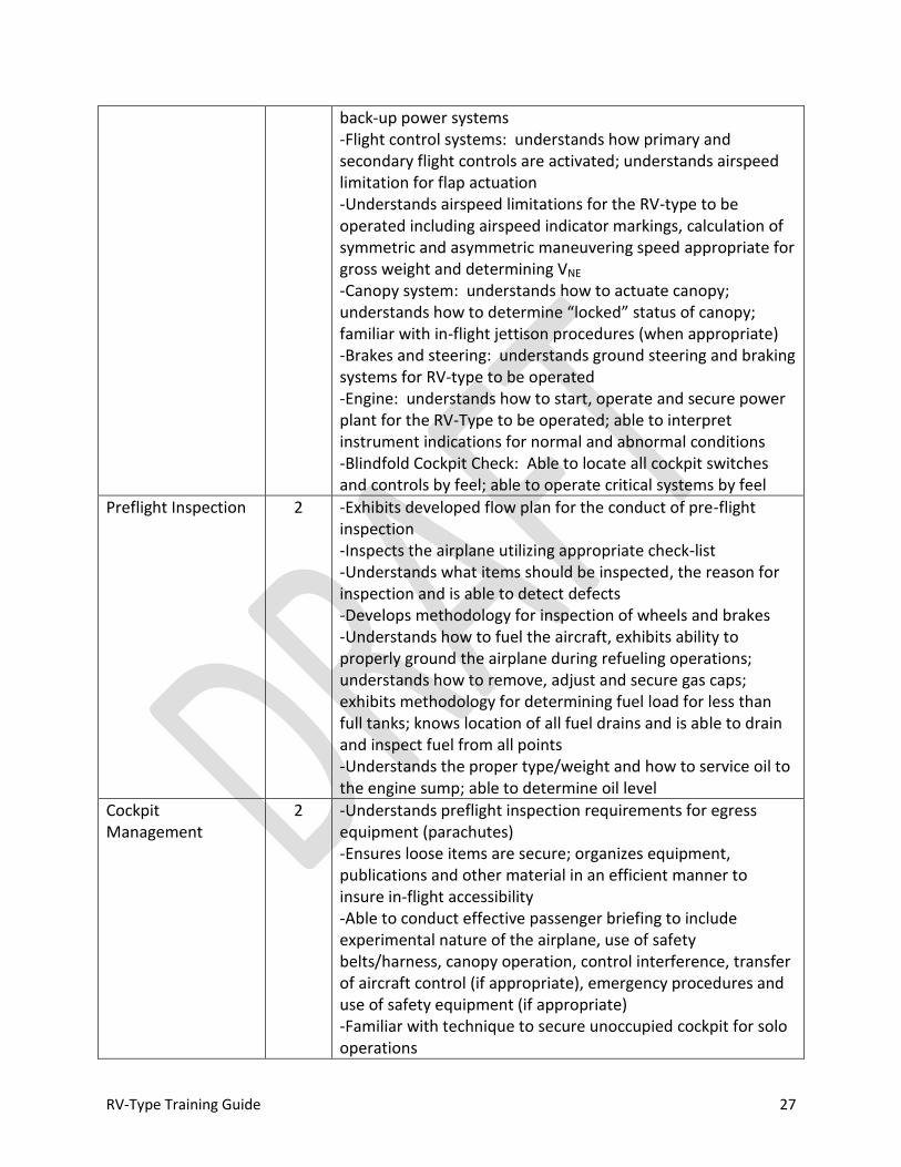
RV-Type Training Guide 27
back-up power systems -Flight control systems: understands how primary and secondary flight controls are activated; understands airspeed limitation for flap actuation -Understands airspeed limitations for the RV-type to be operated including airspeed indicator markings, calculation of symmetric and asymmetric maneuvering speed appropriate for gross weight and determining VNE -Canopy system: understands how to actuate canopy; understands how to determine “locked” status of canopy; familiar with in-flight jettison procedures (when appropriate) -Brakes and steering: understands ground steering and braking systems for RV-type to be operated -Engine: understands how to start, operate and secure power plant for the RV-Type to be operated; able to interpret instrument indications for normal and abnormal conditions -Blindfold Cockpit Check: Able to locate all cockpit switches and controls by feel; able to operate critical systems by feel
Preflight Inspection 2 -Exhibits developed flow plan for the conduct of pre-flight inspection -Inspects the airplane utilizing appropriate check-list -Understands what items should be inspected, the reason for inspection and is able to detect defects -Develops methodology for inspection of wheels and brakes -Understands how to fuel the aircraft, exhibits ability to properly ground the airplane during refueling operations; understands how to remove, adjust and secure gas caps; exhibits methodology for determining fuel load for less than full tanks; knows location of all fuel drains and is able to drain and inspect fuel from all points -Understands the proper type/weight and how to service oil to the engine sump; able to determine oil level
Cockpit Management
2 -Understands preflight inspection requirements for egress equipment (parachutes) -Ensures loose items are secure; organizes equipment, publications and other material in an efficient manner to insure in-flight accessibility -Able to conduct effective passenger briefing to include experimental nature of the airplane, use of safety belts/harness, canopy operation, control interference, transfer of aircraft control (if appropriate), emergency procedures and use of safety equipment (if appropriate) -Familiar with technique to secure unoccupied cockpit for solo operations

RV-Type Training Guide 28
-Understands location and operation of all cockpit switches, circuit breakers and controls -Understands canopy operation; familiar with limitations for operating with canopy open or partially open; understands how to secure and verify security of canopy
Engine Start 2 -Positions aircraft properly with regard to safety of personnel on the ground, structures and surface conditions; demonstrates awareness of prop blast effects at all times -Understands engine manufacturer’s or builder’s recommended engine start procedures for starting, utilizing appropriate checklist -Familiar with cold weather starting procedures; familiar with manufacturer’s recommendations for pre-heating -Familiar with hot starting procedure -Familiar with flooded start procedure -Familiar with ground leaning technique -Understands engine operating limits for ground operations -Familiar with starting and ground operation emergency procedures
Taxi 2 -Demonstrates awareness of prop blast at all times -Performs a brake check prior to taxi -Maneuvers the aircraft with regard to safety of personnel on the ground, structures and surface conditions; taxis to avoid other aircraft and hazards -Understands wind effects; allows for surface conditions and steering effectiveness; properly positions flight controls for taxi operations -Controls taxi direction and speed without excessive use of brakes -Divides attention inside/outside of cockpit; prioritizes and uses techniques to minimize pilot distraction -Understands how to ventilate the cockpit during taxi operations -Complies with markings, signals, clearances and instructions -Utilizes appropriate checklist -Avoids runway incursions
Before Takeoff Check/Run-up Operations
2 -Demonstrates awareness of prop blast at all times -Positions the airplane with regard to other planes, vehicles, obstacles/structures, wind and surface conditions -Understands engine manufacturer’s or builder’s recommended engine run-up procedure; understands engine operating limits; understands temperature requirements for run-up and is able to detect malfunctions -Divides attention inside/outside of cockpit
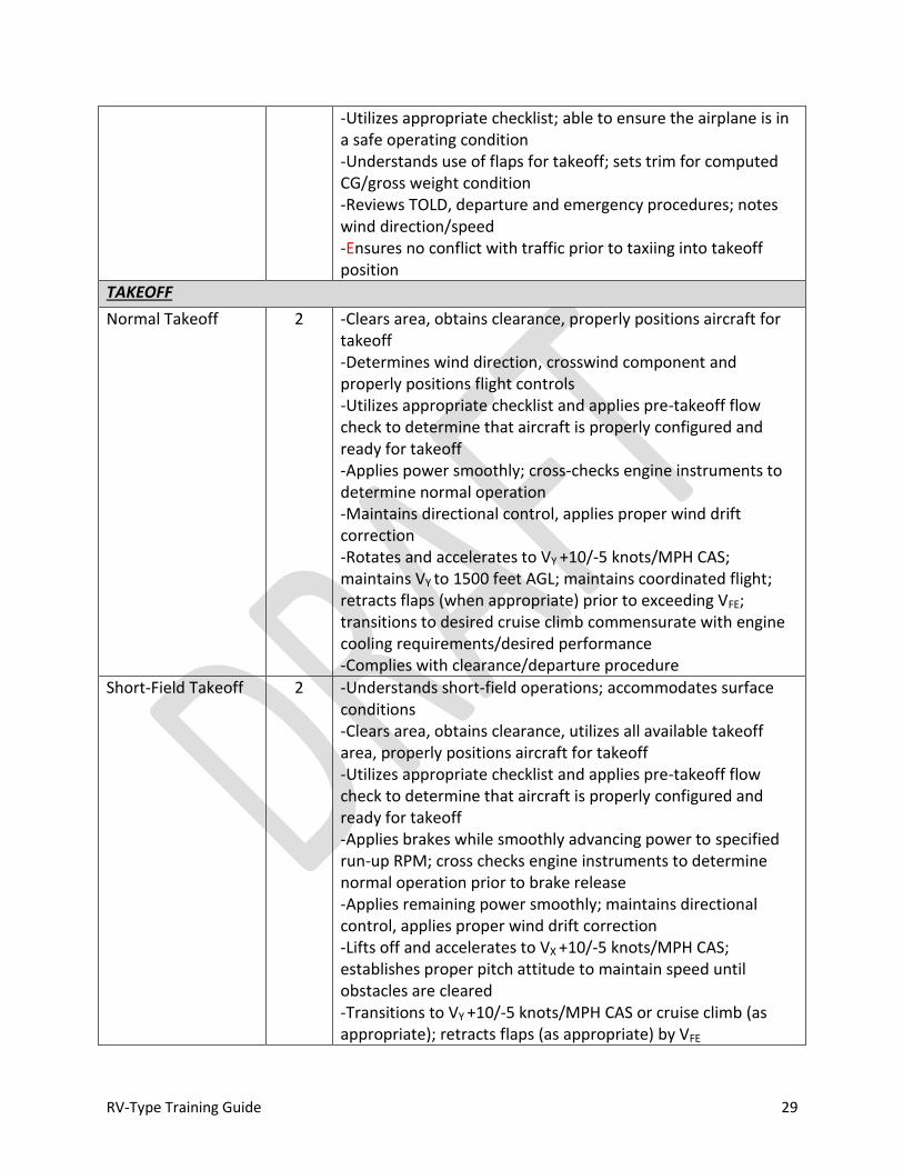
RV-Type Training Guide 29
-Utilizes appropriate checklist; able to ensure the airplane is in a safe operating condition -Understands use of flaps for takeoff; sets trim for computed CG/gross weight condition -Reviews TOLD, departure and emergency procedures; notes wind direction/speed -Ensures no conflict with traffic prior to taxiing into takeoff position
TAKEOFF
Normal Takeoff 2 -Clears area, obtains clearance, properly positions aircraft for takeoff -Determines wind direction, crosswind component and properly positions flight controls -Utilizes appropriate checklist and applies pre-takeoff flow check to determine that aircraft is properly configured and ready for takeoff -Applies power smoothly; cross-checks engine instruments to determine normal operation -Maintains directional control, applies proper wind drift correction -Rotates and accelerates to VY +10/-5 knots/MPH CAS; maintains VY to 1500 feet AGL; maintains coordinated flight; retracts flaps (when appropriate) prior to exceeding VFE; transitions to desired cruise climb commensurate with engine cooling requirements/desired performance -Complies with clearance/departure procedure
Short-Field Takeoff 2 -Understands short-field operations; accommodates surface conditions -Clears area, obtains clearance, utilizes all available takeoff area, properly positions aircraft for takeoff -Utilizes appropriate checklist and applies pre-takeoff flow check to determine that aircraft is properly configured and ready for takeoff -Applies brakes while smoothly advancing power to specified run-up RPM; cross checks engine instruments to determine normal operation prior to brake release -Applies remaining power smoothly; maintains directional control, applies proper wind drift correction -Lifts off and accelerates to VX +10/-5 knots/MPH CAS; establishes proper pitch attitude to maintain speed until obstacles are cleared -Transitions to VY +10/-5 knots/MPH CAS or cruise climb (as appropriate); retracts flaps (as appropriate) by VFE
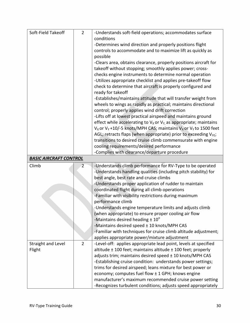
RV-Type Training Guide 30
Soft-Field Takeoff 2 -Understands soft-field operations; accommodates surface conditions -Determines wind direction and properly positions flight controls to accommodate and to maximize lift as quickly as possible -Clears area, obtains clearance, properly positions aircraft for takeoff without stopping; smoothly applies power; cross-checks engine instruments to determine normal operation -Utilizes appropriate checklist and applies pre-takeoff flow check to determine that aircraft is properly configured and ready for takeoff -Establishes/maintains attitude that will transfer weight from wheels to wings as rapidly as practical; maintains directional control; properly applies wind drift correction -Lifts off at lowest practical airspeed and maintains ground effect while accelerating to VX or VY, as appropriate; maintains VX or VY +10/-5 knots/MPH CAS; maintains VX or VY to 1500 feet AGL; retracts flaps (when appropriate) prior to exceeding VFE; transitions to desired cruise climb commensurate with engine cooling requirements/desired performance -Complies with clearance/departure procedure
BASIC AIRCRAFT CONTROL
Climb 2 -Understands climb performance for RV-Type to be operated -Understands handling qualities (including pitch stability) for best angle, best rate and cruise climbs -Understands proper application of rudder to maintain coordinated flight during all climb operations -Familiar with visibility restrictions during maximum performance climb -Understands engine temperature limits and adjusts climb (when appropriate) to ensure proper cooling air flow -Maintains desired heading ± 10o -Maintains desired speed ± 10 knots/MPH CAS -Familiar with techniques for cruise climb altitude adjustment; applies appropriate power/mixture adjustment
Straight and Level Flight
2 -Level-off: applies appropriate lead point, levels at specified altitude ± 100 feet; maintains altitude ± 100 feet; properly adjusts trim; maintains desired speed ± 10 knots/MPH CAS -Establishing cruise condition: understands power settings; trims for desired airspeed; leans mixture for best power or economy; computes fuel flow ± 1 GPH; knows engine manufacturer’s maximum recommended cruise power setting -Recognizes turbulent conditions; adjusts speed appropriately

RV-Type Training Guide 31
Descent 2 -Descent point: able to compute cruise descent point ± 1 NM; plans descent with sufficient VVI to meet crossing restriction ± 1 NM; understands speed limitations; monitors engine condition; conducts descent check -Actively manages mixture control during descent -Level-off: applies appropriate lead point, levels at specified altitude ± 100 feet -Familiar with techniques for cruise descent altitude adjustment; applies appropriate power/mixture adjustment -Familiar with high descent rates at low speed -Glide: Understands glide performance; able to establish max endurance glide ± 10 knots/MPH CAS; able to establish max range glide ± 10 knots/MPH CAS; knows nominal sink rate for RV-Type to be operated; knows glide ratio for RV-type to be operated; knows power-off glide angle for RV-type to be operated; familiar with prop-stopped glide
Standard Rate Turns 2 -Understands instrument indications for establishing a 3o per second turn
Medium Banked Turns
2 -Smoothly establishes 30o bank ± 5o; applies appropriate rudder to coordinate turn with no more than ½ ball-width error; establishes appropriate back pressure to maintain altitude ± 100 feet; computes lead-point for roll out and rolls out ± 10o of specified heading; maintains airspeed ± 10 knots/MPH CAS throughout -Divides attention between aircraft control, orientation, and clearing
Steep Turns 2 -Smoothly establishes 45o or 60o bank ± 5o; applies appropriate rudder to coordinate turn with no more than ½ ball-width error; establishes appropriate back pressure and power; maintains altitude ± 100 feet; computes lead-point for roll out and rolls out ± 10o of specified heading; maintains airspeed ± 10 Knots/MPH CAS when appropriate; -Divides attention between aircraft control, orientation, and clearing
SLOW FLIGHT AND STALLS
Slow Flight 2 -Selects appropriate altitude for maneuvering in accordance with training rules and/or local restrictions (in no case lower than 1500 feet AGL) -Properly configures the aircraft -Establishes/maintains airspeed at which any further increase in AOA or load factor would result in a stall; maintains speed +10/-0 knots/MPH CAS -Accomplishes coordinated straight and level flight, turns,
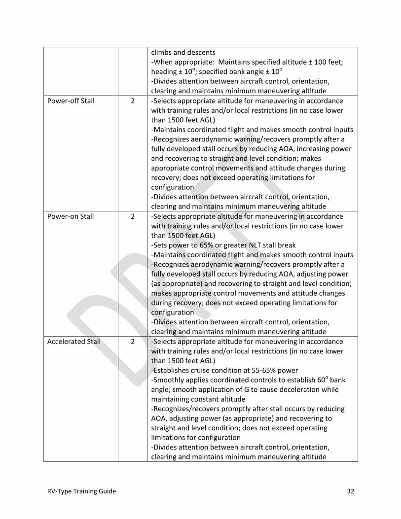
RV-Type Training Guide 32
climbs and descents -When appropriate: Maintains specified altitude ± 100 feet; heading ± 10o; specified bank angle ± 10o -Divides attention between aircraft control, orientation, clearing and maintains minimum maneuvering altitude
Power-off Stall 2 -Selects appropriate altitude for maneuvering in accordance with training rules and/or local restrictions (in no case lower than 1500 feet AGL) -Maintains coordinated flight and makes smooth control inputs -Recognizes aerodynamic warning/recovers promptly after a fully developed stall occurs by reducing AOA, increasing power and recovering to straight and level condition; makes appropriate control movements and attitude changes during recovery; does not exceed operating limitations for configuration -Divides attention between aircraft control, orientation, clearing and maintains minimum maneuvering altitude
Power-on Stall 2 -Selects appropriate altitude for maneuvering in accordance with training rules and/or local restrictions (in no case lower than 1500 feet AGL) -Sets power to 65% or greater NLT stall break -Maintains coordinated flight and makes smooth control inputs -Recognizes aerodynamic warning/recovers promptly after a fully developed stall occurs by reducing AOA, adjusting power (as appropriate) and recovering to straight and level condition; makes appropriate control movements and attitude changes during recovery; does not exceed operating limitations for configuration -Divides attention between aircraft control, orientation, clearing and maintains minimum maneuvering altitude
Accelerated Stall 2 -Selects appropriate altitude for maneuvering in accordance with training rules and/or local restrictions (in no case lower than 1500 feet AGL) -Establishes cruise condition at 55-65% power -Smoothly applies coordinated controls to establish 60o bank angle; smooth application of G to cause deceleration while maintaining constant altitude -Recognizes/recovers promptly after stall occurs by reducing AOA, adjusting power (as appropriate) and recovering to straight and level condition; does not exceed operating limitations for configuration -Divides attention between aircraft control, orientation, clearing and maintains minimum maneuvering altitude

RV-Type Training Guide 33
UNUSUAL ATTITUDES
Nose-High Unusual Attitude
2 -Recognizes and confirms an unusual attitude exists -Applies smooth control inputs; maintain awareness of airspeed -Neutralizes aileron and rudder inputs; establishes 0 to ½ G condition -Adjusts power and bank as necessary to assist pitch and airspeed control; avoids negative G -As the nose approaches the horizon with adequate airspeed, adjusts pitch, bank and power to re-establish straight and level flight
Nose-Low Unusual Attitude
2 -Recognizes and confirms an unusual attitude exists -Applies smooth control inputs; maintains awareness of airspeed and adjusts power appropriately; avoids over G
CONFIDENCE MANEUVERS (Advanced Tracks)
Lazy-Eight / Wing-over
1 -Establishes 55-65% cruise condition -Maintains constant pitch and roll rates throughout maneuver using smooth control inputs -Coordinates control inputs -Heading ± 15o from entry reference at 180o points -Airspeed ± 25 knots/MPH CAS (not to exceed VNO) from entry reference speed For maximum performance maneuvering: degrees of roll approximately equal to degrees of heading change (i.e., nose slicing through the horizon with 90o bank at 90o turn point). -With instructor assistance, divides attention between aircraft control, orientation, clearing and maintains minimum maneuvering altitude
Chandelle
1 -Establishes 55-65% cruise condition -Simultaneous application of power and smooth pitch and roll inputs to establish 45-60o bank by 45oturn point; maintains bank until 135o point -Coordinates control inputs -Completes roll out at 180o point ± 15o at speed slightly above stall -With instructor assistance, divides attention between aircraft control, orientation, clearing and maintains minimum maneuvering altitude
AOA Recovery 2 -Understands “Unload for Control” concept -Smoothly retards the throttle to Idle-1500 RPM -Smoothly establishes and maintains 0 to ½ G condition with neutral controls -Coordinates recovery inputs
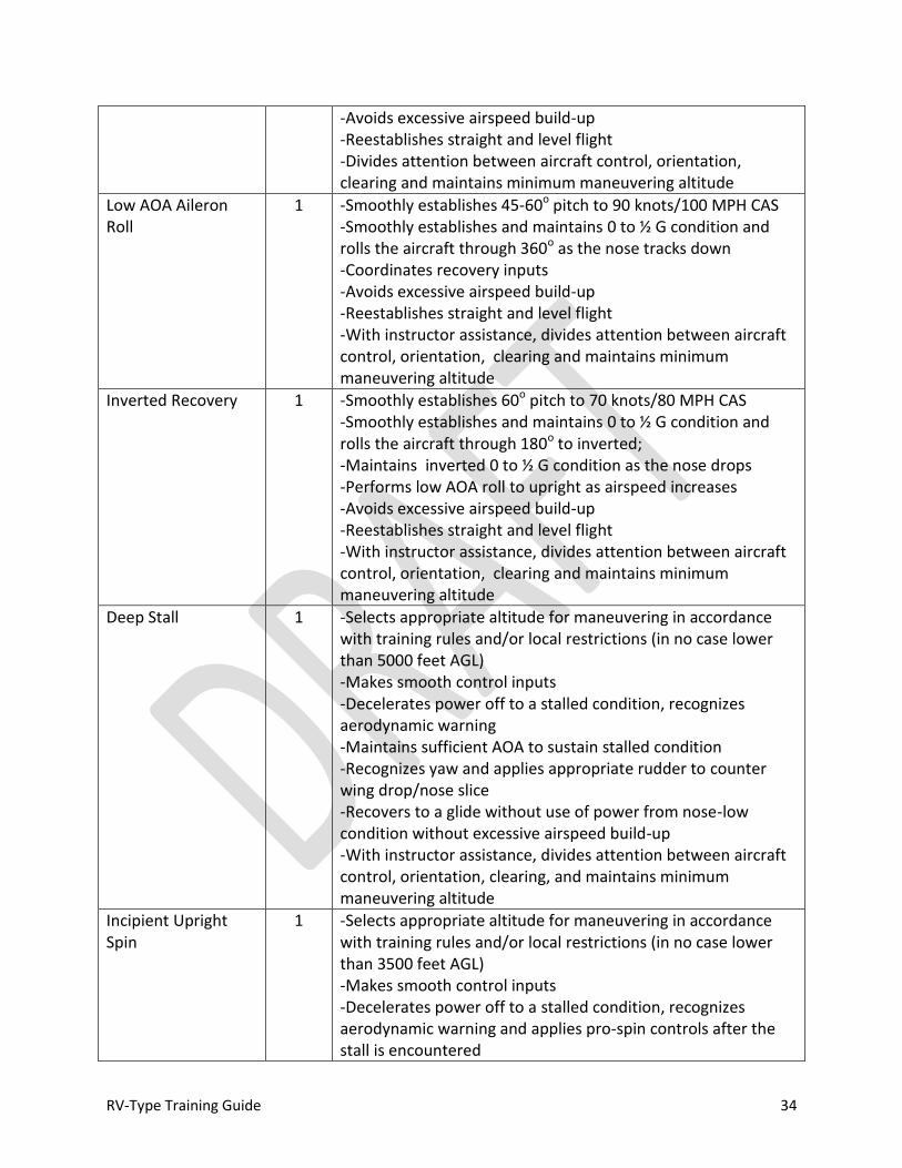
RV-Type Training Guide 34
-Avoids excessive airspeed build-up -Reestablishes straight and level flight -Divides attention between aircraft control, orientation, clearing and maintains minimum maneuvering altitude
Low AOA Aileron Roll
1 -Smoothly establishes 45-60o pitch to 90 knots/100 MPH CAS -Smoothly establishes and maintains 0 to ½ G condition and rolls the aircraft through 360o as the nose tracks down -Coordinates recovery inputs -Avoids excessive airspeed build-up -Reestablishes straight and level flight -With instructor assistance, divides attention between aircraft control, orientation, clearing and maintains minimum maneuvering altitude
Inverted Recovery 1 -Smoothly establishes 60o pitch to 70 knots/80 MPH CAS -Smoothly establishes and maintains 0 to ½ G condition and rolls the aircraft through 180o to inverted; -Maintains inverted 0 to ½ G condition as the nose drops -Performs low AOA roll to upright as airspeed increases -Avoids excessive airspeed build-up -Reestablishes straight and level flight -With instructor assistance, divides attention between aircraft control, orientation, clearing and maintains minimum maneuvering altitude
Deep Stall 1 -Selects appropriate altitude for maneuvering in accordance with training rules and/or local restrictions (in no case lower than 5000 feet AGL) -Makes smooth control inputs -Decelerates power off to a stalled condition, recognizes aerodynamic warning -Maintains sufficient AOA to sustain stalled condition -Recognizes yaw and applies appropriate rudder to counter wing drop/nose slice -Recovers to a glide without use of power from nose-low condition without excessive airspeed build-up -With instructor assistance, divides attention between aircraft control, orientation, clearing, and maintains minimum maneuvering altitude
Incipient Upright Spin
1 -Selects appropriate altitude for maneuvering in accordance with training rules and/or local restrictions (in no case lower than 3500 feet AGL) -Makes smooth control inputs -Decelerates power off to a stalled condition, recognizes aerodynamic warning and applies pro-spin controls after the stall is encountered
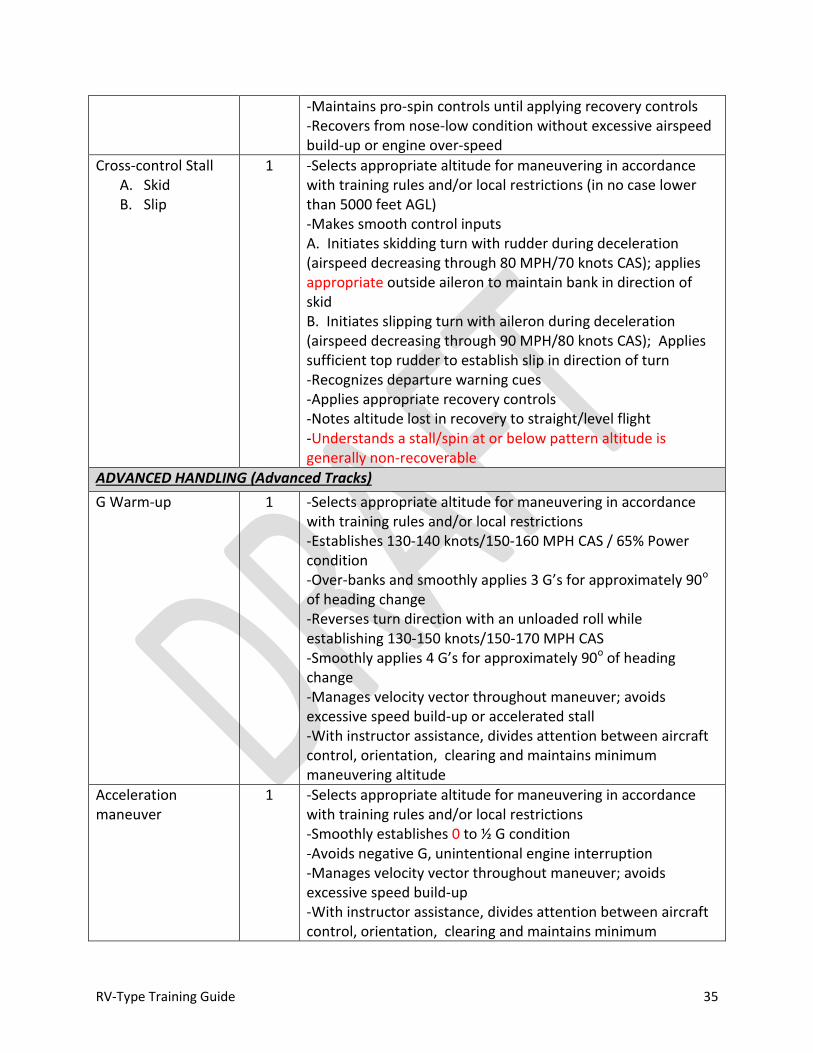
RV-Type Training Guide 35
-Maintains pro-spin controls until applying recovery controls -Recovers from nose-low condition without excessive airspeed build-up or engine over-speed
Cross-control Stall A. Skid B. Slip
1 -Selects appropriate altitude for maneuvering in accordance with training rules and/or local restrictions (in no case lower than 5000 feet AGL) -Makes smooth control inputs A. Initiates skidding turn with rudder during deceleration (airspeed decreasing through 80 MPH/70 knots CAS); applies appropriate outside aileron to maintain bank in direction of skid B. Initiates slipping turn with aileron during deceleration (airspeed decreasing through 90 MPH/80 knots CAS); Applies sufficient top rudder to establish slip in direction of turn -Recognizes departure warning cues -Applies appropriate recovery controls -Notes altitude lost in recovery to straight/level flight -Understands a stall/spin at or below pattern altitude is generally non-recoverable
ADVANCED HANDLING (Advanced Tracks)
G Warm-up 1 -Selects appropriate altitude for maneuvering in accordance with training rules and/or local restrictions -Establishes 130-140 knots/150-160 MPH CAS / 65% Power condition -Over-banks and smoothly applies 3 G’s for approximately 90o of heading change -Reverses turn direction with an unloaded roll while establishing 130-150 knots/150-170 MPH CAS -Smoothly applies 4 G’s for approximately 90o of heading change -Manages velocity vector throughout maneuver; avoids excessive speed build-up or accelerated stall -With instructor assistance, divides attention between aircraft control, orientation, clearing and maintains minimum maneuvering altitude
Acceleration maneuver
1 -Selects appropriate altitude for maneuvering in accordance with training rules and/or local restrictions -Smoothly establishes 0 to ½ G condition -Avoids negative G, unintentional engine interruption -Manages velocity vector throughout maneuver; avoids excessive speed build-up -With instructor assistance, divides attention between aircraft control, orientation, clearing and maintains minimum

RV-Type Training Guide 36
maneuvering altitude
Basic Roll 1 -Selects appropriate altitude for maneuvering in accordance with training rules and/or local restrictions (in no case lower than 1500 feet AGL) -Establishes 125-150 knots/140-170 MPH CAS / 65-75% Power condition -Smoothly applies back stick to establish 20-30o nose up -Unloads to neutralize elevator input then applies smooth aileron input in desired direction of roll; maintains sufficient roll rate to ensure return to upright attitude no later than 20-30o nose low --With instructor assistance, divides attention between aircraft control, orientation, clearing and maintains minimum maneuvering altitude
Loop 1 -Selects appropriate altitude for maneuvering in accordance with training rules and/or local restrictions -Establishes 150-160 knots/170-180 MPH CAS / FULL power condition; does not exceed VNO or engine red line RPM -Smoothly applies 3-4 G’s -Eases back pressure as pitch exceeds 90o nose up, but maintains sufficient pressure to ensure nose continues to track -Apexes inverted at ½ to 1 (positive) G at 60-80 knots/70-90 MPH CAS -Reduces power (when appropriate) and smoothly increases G through backside of loop to rate nose; avoids excessive speed build-up; avoids accelerated stall -With instructor assistance, divides attention between aircraft control, orientation, clearing and maintains minimum maneuvering altitude
Split-S 1 -Selects appropriate altitude for maneuvering in accordance with training rules and/or local restrictions -Manages energy to establish a 10-30o nose up entry condition at 60-80 knots/70-90 MPH CAS -Reduces power to idle and smoothly increases G; avoids excessive speed build-up; avoids accelerated stall -With instructor assistance, divides attention between aircraft control, orientation, clearing and maintains minimum maneuvering altitude
Barrel Roll 1 -Selects appropriate altitude for maneuvering in accordance with training rules and/or local restrictions -Establishes 130-160 knots/150-180 MPH CAS (not to exceed VNO) / 65-75% condition -Selects suitable reference point; offsets 20-30o using a coordinated turn
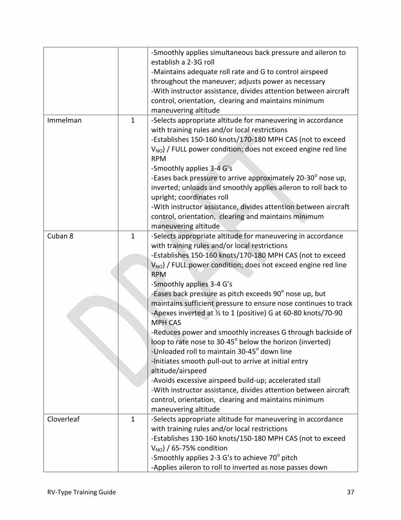
RV-Type Training Guide 37
-Smoothly applies simultaneous back pressure and aileron to establish a 2-3G roll -Maintains adequate roll rate and G to control airspeed throughout the maneuver; adjusts power as necessary -With instructor assistance, divides attention between aircraft control, orientation, clearing and maintains minimum maneuvering altitude
Immelman 1 -Selects appropriate altitude for maneuvering in accordance with training rules and/or local restrictions -Establishes 150-160 knots/170-180 MPH CAS (not to exceed VNO) / FULL power condition; does not exceed engine red line RPM -Smoothly applies 3-4 G’s -Eases back pressure to arrive approximately 20-30o nose up, inverted; unloads and smoothly applies aileron to roll back to upright; coordinates roll -With instructor assistance, divides attention between aircraft control, orientation, clearing and maintains minimum maneuvering altitude
Cuban 8 1 -Selects appropriate altitude for maneuvering in accordance with training rules and/or local restrictions -Establishes 150-160 knots/170-180 MPH CAS (not to exceed VNO) / FULL power condition; does not exceed engine red line RPM -Smoothly applies 3-4 G’s -Eases back pressure as pitch exceeds 90o nose up, but maintains sufficient pressure to ensure nose continues to track -Apexes inverted at ½ to 1 (positive) G at 60-80 knots/70-90 MPH CAS -Reduces power and smoothly increases G through backside of loop to rate nose to 30-45o below the horizon (inverted) -Unloaded roll to maintain 30-45o down line -Initiates smooth pull-out to arrive at initial entry altitude/airspeed -Avoids excessive airspeed build-up; accelerated stall -With instructor assistance, divides attention between aircraft control, orientation, clearing and maintains minimum maneuvering altitude
Cloverleaf 1 -Selects appropriate altitude for maneuvering in accordance with training rules and/or local restrictions -Establishes 130-160 knots/150-180 MPH CAS (not to exceed VNO) / 65-75% condition -Smoothly applies 2-3 G’s to achieve 70o pitch -Applies aileron to roll to inverted as nose passes down

RV-Type Training Guide 38
through horizon 90o from original entry heading -Smooth back pressure to re-establish entry conditions; adjusts power as required -Avoids excessive airspeed build-up; accelerated stall -With instructor assistance, divides attention between aircraft control, orientation, clearing and maintains minimum maneuvering altitude
PATTERN AND LANDING
Emergency Landing 2 -Selects appropriate Glide Speed -Selects suitable site for emergency landing -Completes appropriate emergency procedures to effect re-start and/or secure; notifies ATC; squawks 7700 -Arrives at High Key position aligned with landing direction +500 / -0 feet of 1500’ AGL at a speed ≥ 105 MPH /95 Knots CAS -Establishes low key 1000’ AGL ± 200’ at 80 MPH / 70 Knots ± 10 Knots/MPH CAS -Arrives at selected landing site with sufficient energy to land
Descent Check 2 -Understands induction system and how to prevent icing/operate alternate air -Utilizes appropriate checklist: basic “GUMPS” flow prior to all descents and landings
Pattern Operations/ Perch Management
2 -Maintains pattern altitude ± 100 feet -Arrives at perch +10/-5 knots/MPH of desired airspeed; maintains throughout base turn -Applies appropriate wind correction to maintain desired ground track -Adjusts perch point for wind conditions
Low-Approach / Go-Around
2 -Makes timely decision -Smoothly applies takeoff power; maintains directional control; adjusts pitch for VX or VY climb (as appropriate) +10/-5 knots/MPH CAS to safe altitude; maintains coordinated flight -Adjusts trim; retracts flaps no later than VFE -Maneuvers as required to clear traffic/hazards -Applies appropriate wind drift correction -Utilizes appropriate checklist
Slip 2 -Understands proper control inputs to establish a forward and side slip; maintains AOA/airspeed awareness -For the purpose of glide path adjustment during approach to landing: Makes smooth, timely and correct control application during recovery from the slip -For the purpose of cross-wind landing: establishes a forward slip in a timely manner during the transition to landing;

RV-Type Training Guide 39
maintains desired ground track with longitudinal axis aligned with the landing surface to touchdown
Normal Landing 2 -Considers wind conditions, landing surface, obstructions and selects suitable TDZ -Establishes stabilized final approach; maintains speed of 1.3-1.4 VS0 +10/-5 knots/MPH CAS (or L/DMAX if equipped with AOA); applies gust correction -Makes smooth, timely and correct control applications during round out and touchdown -Touches down within first 500 feet of usable surface with no drift/longitudinal axis aligned with landing surface -Maintains cross-wind correction and directional control throughout approach and landing -Complies with approach/clearance procedure -Utilizes appropriate checklist
180o Power-off Landing
2 -Familiar with energy management techniques to accomplish a 180o power-off approach from a 1000 foot AGL low key through touchdown on a suitable landing surface - Considers wind conditions, landing surface, obstructions and selects suitable TDZ -Utilizes appropriate glide speed to transition to final approach speed no slower than 1.3-1.4 VS0 +10/-5 knots/MPH CAS (or L/DMAX if equipped with AOA) -Touches down in normal landing attitude within the first 1/2 of usable surface or at a suitable touchdown point that would allow a full stop landing without application of abnormal braking on the landing surface available with no drift/longitudinal axis aligned with landing surface -Maintains cross-wind correction and directional control throughout approach and landing Complies with approach/clearance procedure -Utilizes appropriate checklist
Short-Field Landing 2 -Considers wind conditions, landing surface, obstructions and selects suitable TDZ -Maintains stabilized approach speed not greater than 11.3-1.4 VS0 +10/-5 knots/MPH CAS (or L/DMAX if equipped with AOA) -Makes smooth, timely and correct control application during the round out and touchdown -Touches down smoothly at minimum control airspeed at or within 200 feet of planned TDZ with no side drift, minimum float and longitudinal axis aligned with landing path -Maintains cross-wind correction and directional control throughout the approach and landing sequence -Applies brakes and flight controls as necessary to stop in the

RV-Type Training Guide 40
shortest distance consistent with safety -Utilizes appropriate checklist
Soft-Field Landing 2 -Considers wind conditions, landing surface, obstructions and selects suitable TDZ -Maintains stabilized approach speed not greater than 1.3-1.4 VS0 +10/-5 knots/MPH CAS (or L/DMAX if equipped with AOA) -Makes smooth, timely and correct control application during the round out and touchdown -Touches down softly with no drift and longitudinal axis aligned with landing path -Maintains cross-wind correction and directional control throughout the approach and landing sequence -Utilizes proper flight controls, speed and power to taxi on the soft surface -Utilizes appropriate checklist
AFTER LANDING
After landing, parking and securing
2 -Maintains directional control -Observes markings/procedures/clearance(s) -Parks in appropriate area; considers safety of airplane, persons and property on the ground -Utilizes appropriate checklist -Familiar with techniques for moving the airplane after shutdown -Conducts post-flight inspection; secures the aircraft
Servicing 2 -Understands how to fuel the aircraft, exhibits ability to properly ground the airplane during refueling operations; understands how to remove, adjust and secure gas caps; exhibits methodology for determining fuel load for less than full tanks; knows location of all fuel drains and is able to drain and inspect fuel from all points -Understands the proper type/weight and how to service oil to the engine sump; able to determine oil level
AIRMANSHIP
Clearing / Visual Look-out
2 -Utilizes proper scanning techniques -Maneuvers as required to ensure flight path is clear of traffic -Maintains situational awareness of other aircraft operating on frequency/sharing the traffic pattern -Understands and applies right of way rules
Fuel Management 2 -Determines fuel requirements and ensures proper fuel load for the conduct of the flight; ensures sufficient fuel reserve at all times -Monitors fuel level throughout the flight -Computes appropriate BINGO fuel

RV-Type Training Guide 41
-Maintains fuel levels sufficient for lateral balance
Airmanship 2 -Understands aircraft capabilities and limitations -Able to navigate; maintains orientation - Adheres to training rules, procedures and regulations -Utilizes resources effectively -Recognizes fatigue and degraded performance -Manages cockpit workload effectively; prioritizes
Judgment (ORM/ADM)
2 - Identifies risks/hazards, analyzes controls, makes control decisions and monitors results -Understands pilot capabilities: establishes and adheres to personal limitations -Applies appropriate prioritization to ensure safety
Table 1-4: Objectives/Standards of Behavior for Individual Flight Elements For Instructor Upgrade
Element Min Grade
Req
Objectives/Standards of Behavior
GROUND OPERATIONS
Weather / NOTAM Information
2 -Able to instruct an upgrading pilot how to obtain sufficient information from an FAA approved source to make Go / No-Go decision for conduct of flight -Understands and is able to instruct airspace requirements/limitations and temporary flight restrictions
TOLD (Takeoff and Landing Data)
2 -Able to compute or estimate takeoff and landing performance; able to determine runway requirements for safe operation under existing conditions; able to compute decision points and able to offer performance estimation techniques to upgrading pilots with limited performance information available -Understands and is able to instruct factors affecting performance and able to apply appropriate takeoff and landing safety factors -Understands and is able to instruct Koch Chart for density altitude effects -Understands and is able to instruct Designer’s Performance Specifications; understands difference between those specifications and specific RV-Type to be operated
EAB Airworthiness Determination
2 -Understands and is able to instruct EAB airworthiness requirements and is able to make a determination as to the airworthiness of the airplane to be operated -Understands and is able to instruct requirements documents
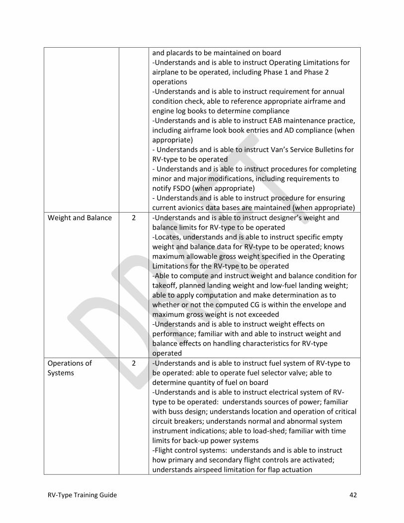
RV-Type Training Guide 42
and placards to be maintained on board -Understands and is able to instruct Operating Limitations for airplane to be operated, including Phase 1 and Phase 2 operations -Understands and is able to instruct requirement for annual condition check, able to reference appropriate airframe and engine log books to determine compliance -Understands and is able to instruct EAB maintenance practice, including airframe look book entries and AD compliance (when appropriate) - Understands and is able to instruct Van’s Service Bulletins for RV-type to be operated - Understands and is able to instruct procedures for completing minor and major modifications, including requirements to notify FSDO (when appropriate) - Understands and is able to instruct procedure for ensuring current avionics data bases are maintained (when appropriate)
Weight and Balance 2 -Understands and is able to instruct designer’s weight and balance limits for RV-type to be operated -Locates, understands and is able to instruct specific empty weight and balance data for RV-type to be operated; knows maximum allowable gross weight specified in the Operating Limitations for the RV-type to be operated -Able to compute and instruct weight and balance condition for takeoff, planned landing weight and low-fuel landing weight; able to apply computation and make determination as to whether or not the computed CG is within the envelope and maximum gross weight is not exceeded -Understands and is able to instruct weight effects on performance; familiar with and able to instruct weight and balance effects on handling characteristics for RV-type operated
Operations of Systems
2 -Understands and is able to instruct fuel system of RV-type to be operated: able to operate fuel selector valve; able to determine quantity of fuel on board -Understands and is able to instruct electrical system of RV-type to be operated: understands sources of power; familiar with buss design; understands location and operation of critical circuit breakers; understands normal and abnormal system instrument indications; able to load-shed; familiar with time limits for back-up power systems -Flight control systems: understands and is able to instruct how primary and secondary flight controls are activated; understands airspeed limitation for flap actuation
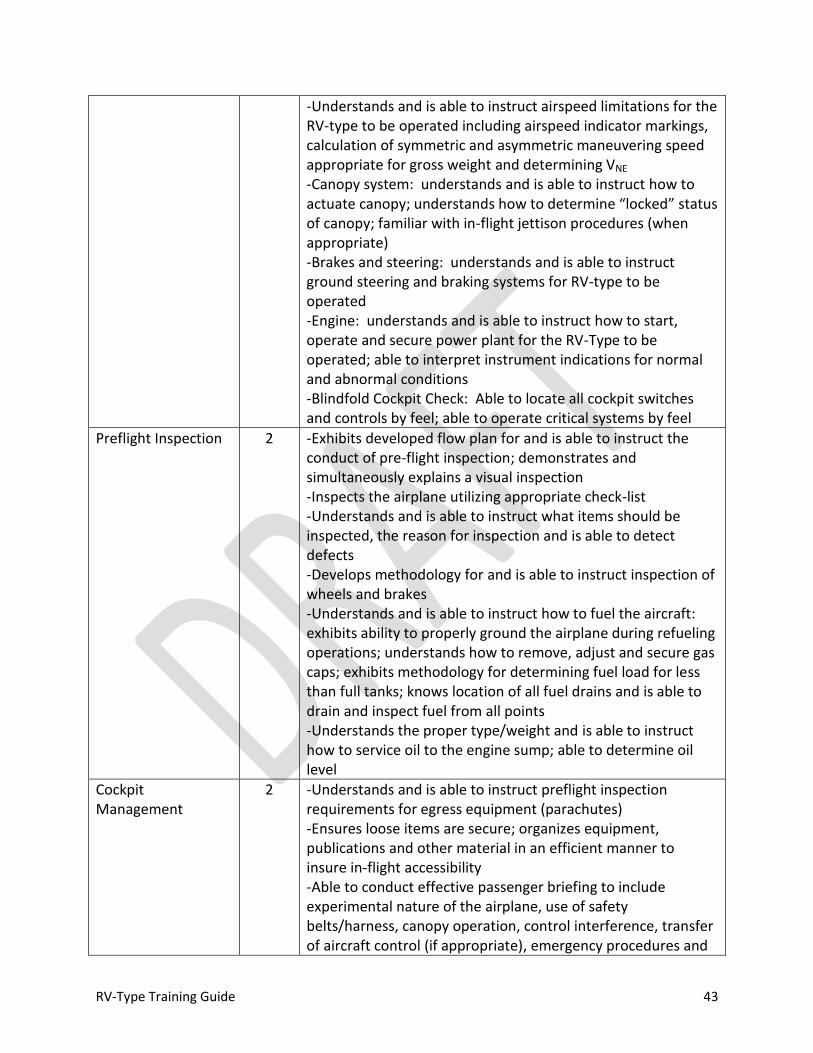
RV-Type Training Guide 43
-Understands and is able to instruct airspeed limitations for the RV-type to be operated including airspeed indicator markings, calculation of symmetric and asymmetric maneuvering speed appropriate for gross weight and determining VNE -Canopy system: understands and is able to instruct how to actuate canopy; understands how to determine “locked” status of canopy; familiar with in-flight jettison procedures (when appropriate) -Brakes and steering: understands and is able to instruct ground steering and braking systems for RV-type to be operated -Engine: understands and is able to instruct how to start, operate and secure power plant for the RV-Type to be operated; able to interpret instrument indications for normal and abnormal conditions -Blindfold Cockpit Check: Able to locate all cockpit switches and controls by feel; able to operate critical systems by feel
Preflight Inspection 2 -Exhibits developed flow plan for and is able to instruct the conduct of pre-flight inspection; demonstrates and simultaneously explains a visual inspection -Inspects the airplane utilizing appropriate check-list -Understands and is able to instruct what items should be inspected, the reason for inspection and is able to detect defects -Develops methodology for and is able to instruct inspection of wheels and brakes -Understands and is able to instruct how to fuel the aircraft: exhibits ability to properly ground the airplane during refueling operations; understands how to remove, adjust and secure gas caps; exhibits methodology for determining fuel load for less than full tanks; knows location of all fuel drains and is able to drain and inspect fuel from all points -Understands the proper type/weight and is able to instruct how to service oil to the engine sump; able to determine oil level
Cockpit Management
2 -Understands and is able to instruct preflight inspection requirements for egress equipment (parachutes) -Ensures loose items are secure; organizes equipment, publications and other material in an efficient manner to insure in-flight accessibility -Able to conduct effective passenger briefing to include experimental nature of the airplane, use of safety belts/harness, canopy operation, control interference, transfer of aircraft control (if appropriate), emergency procedures and
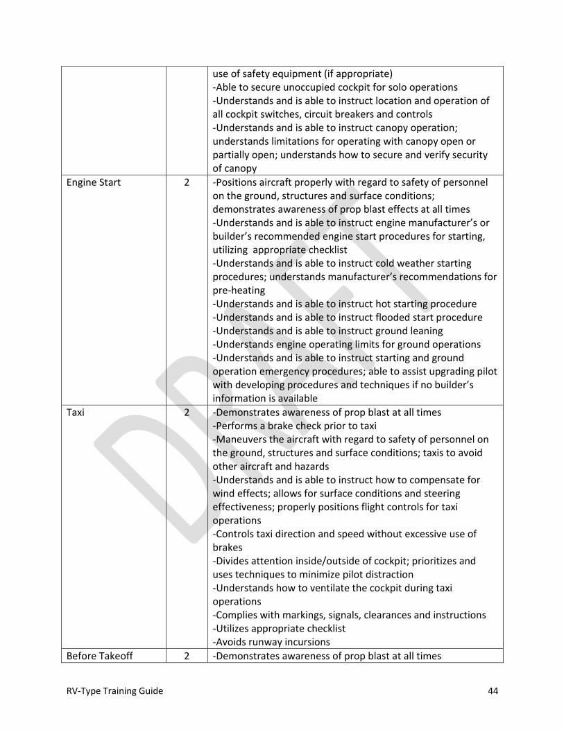
RV-Type Training Guide 44
use of safety equipment (if appropriate) -Able to secure unoccupied cockpit for solo operations -Understands and is able to instruct location and operation of all cockpit switches, circuit breakers and controls -Understands and is able to instruct canopy operation; understands limitations for operating with canopy open or partially open; understands how to secure and verify security of canopy
Engine Start 2 -Positions aircraft properly with regard to safety of personnel on the ground, structures and surface conditions; demonstrates awareness of prop blast effects at all times -Understands and is able to instruct engine manufacturer’s or builder’s recommended engine start procedures for starting, utilizing appropriate checklist -Understands and is able to instruct cold weather starting procedures; understands manufacturer’s recommendations for pre-heating -Understands and is able to instruct hot starting procedure -Understands and is able to instruct flooded start procedure -Understands and is able to instruct ground leaning -Understands engine operating limits for ground operations -Understands and is able to instruct starting and ground operation emergency procedures; able to assist upgrading pilot with developing procedures and techniques if no builder’s information is available
Taxi 2 -Demonstrates awareness of prop blast at all times -Performs a brake check prior to taxi -Maneuvers the aircraft with regard to safety of personnel on the ground, structures and surface conditions; taxis to avoid other aircraft and hazards -Understands and is able to instruct how to compensate for wind effects; allows for surface conditions and steering effectiveness; properly positions flight controls for taxi operations -Controls taxi direction and speed without excessive use of brakes -Divides attention inside/outside of cockpit; prioritizes and uses techniques to minimize pilot distraction -Understands how to ventilate the cockpit during taxi operations -Complies with markings, signals, clearances and instructions -Utilizes appropriate checklist -Avoids runway incursions
Before Takeoff 2 -Demonstrates awareness of prop blast at all times

RV-Type Training Guide 45
Check/Run-up Operations
-Positions the airplane with regard to other planes, vehicles, obstacles/structures, wind and surface conditions -Understands and is able to instruct engine manufacturer’s or builder’s recommended engine run-up procedure: understands engine operating limits; understands temperature requirements for run-up and is able to detect malfunctions -Divides attention inside/outside of cockpit -Utilizes appropriate checklist; able to ensure the airplane is in a safe operating condition -Understands and is able to instruct use of flaps and trim for takeoff -Reviews TOLD, departure and emergency procedures; notes wind direction/speed -Ensures no conflict with traffic prior to taxiing into takeoff position
TAKEOFF
Normal Takeoff 2 -Understands and is able to instruct techniques and procedures for a normal and crosswind takeoff and rejected (aborted) takeoff -Clears area, obtains clearance, properly positions aircraft for takeoff -Determines wind direction, crosswind component and properly positions flight controls -Utilizes appropriate checklist and applies pre-takeoff flow check to determine that aircraft is properly configured and ready for takeoff -Applies power smoothly; cross-checks engine instruments to determine normal operation -Maintains directional control, applies proper wind drift correction -Rotates and accelerates to VY ± 5 knots/MPH CAS; maintains VY ± 5 knots/MPH CAS to 1500 feet AGL; maintains coordinated flight; retracts flaps (when appropriate) prior to exceeding VFE; transitions to desired cruise climb commensurate with engine cooling requirements/desired performance -Complies with clearance/departure procedure
Short-Field Takeoff 2 -Understands and is able to instruct short-field operations; accommodates surface conditions -Clears area, obtains clearance, utilizes all available takeoff area, properly positions aircraft for takeoff -Utilizes appropriate checklist and applies pre-takeoff flow check to determine that aircraft is properly configured and
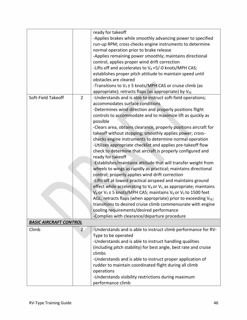
RV-Type Training Guide 46
ready for takeoff -Applies brakes while smoothly advancing power to specified run-up RPM; cross checks engine instruments to determine normal operation prior to brake release -Applies remaining power smoothly; maintains directional control, applies proper wind drift correction -Lifts off and accelerates to VX +5/-0 knots/MPH CAS; establishes proper pitch attitude to maintain speed until obstacles are cleared -Transitions to VY ± 5 knots/MPH CAS or cruise climb (as appropriate); retracts flaps (as appropriate) by VFE
Soft-Field Takeoff 2 -Understands and is able to instruct soft-field operations; accommodates surface conditions -Determines wind direction and properly positions flight controls to accommodate and to maximize lift as quickly as possible -Clears area, obtains clearance, properly positions aircraft for takeoff without stopping; smoothly applies power; cross-checks engine instruments to determine normal operation -Utilizes appropriate checklist and applies pre-takeoff flow check to determine that aircraft is properly configured and ready for takeoff -Establishes/maintains attitude that will transfer weight from wheels to wings as rapidly as practical; maintains directional control; properly applies wind drift correction -Lifts off at lowest practical airspeed and maintains ground effect while accelerating to VX or VY, as appropriate; maintains VX or VY ± 5 knots/MPH CAS; maintains VX or VY to 1500 feet AGL; retracts flaps (when appropriate) prior to exceeding VFE; transitions to desired cruise climb commensurate with engine cooling requirements/desired performance -Complies with clearance/departure procedure
BASIC AIRCRAFT CONTROL
Climb 2 -Understands and is able to instruct climb performance for RV-Type to be operated -Understands and is able to instruct handling qualities (including pitch stability) for best angle, best rate and cruise climbs -Understands and is able to instruct proper application of rudder to maintain coordinated flight during all climb operations -Understands visibility restrictions during maximum performance climb

RV-Type Training Guide 47
-Understands and is able to instruct engine temperature limits and adjusts climb (when appropriate) to ensure proper cooling air flow -Maintains desired heading ± 10o -Maintains desired speed ± 5 knots/MPH CAS -Understands and is able to instruct techniques for cruise climb altitude adjustment; applies appropriate power/mixture adjustment
Straight and Level Flight
2 -Level-off: applies appropriate lead point, levels at specified altitude ± 50 feet; maintains altitude ± 50 feet; properly adjusts trim; maintains airspeed ± 5 knots/MPH CAS -Establishing cruise condition: understands and is able to instruct power settings; trims for desired airspeed; leans mixture for best power or economy; computes fuel flow ± 1 GPH; knows engine manufacturer’s maximum recommended cruise power setting -Recognizes turbulent conditions; adjusts speed appropriately
Descent 2 -Descent point: able to compute and instruct cruise descent point ± 1 NM; plans descent with sufficient VVI to meet crossing restriction ± 1 NM; understands and instructs speed limitations; monitors engine condition; conducts descent check -Actively manages mixture control during descent -Level-off: applies appropriate lead point, levels at specified altitude ± 50 feet -Understands and is able to instruct techniques for cruise descent altitude adjustment; applies appropriate power/mixture adjustment -Understands high descent rates at low speed -Glide: Understands glide performance; able to establish and instruct max endurance glide ± 5 knots/MPH CAS; able to establish and instruct max rang glide ± 5 knots/MPH CAS; understands and is able to instruct nominal sink rate for RV-Type to be operated; understands glide ratio for RV-type to be operated; understands power-off glide angle for RV-type to be operated; understands and is able to instruct prop-stopped glide
Standard Rate Turns 2 -Understands and is able to instruct instrument indications for establishing a 3o per second turn
Medium Banked Turns
2 -Smoothly establishes 30o bank ± 5o; applies appropriate rudder to coordinate turn with no more than ½ ball-width error; establishes appropriate back pressure to maintain altitude ± 50 feet; computes lead-point for roll out and rolls out ± 10o of specified heading; maintains airspeed ± 5 knots/MPH CAS throughout
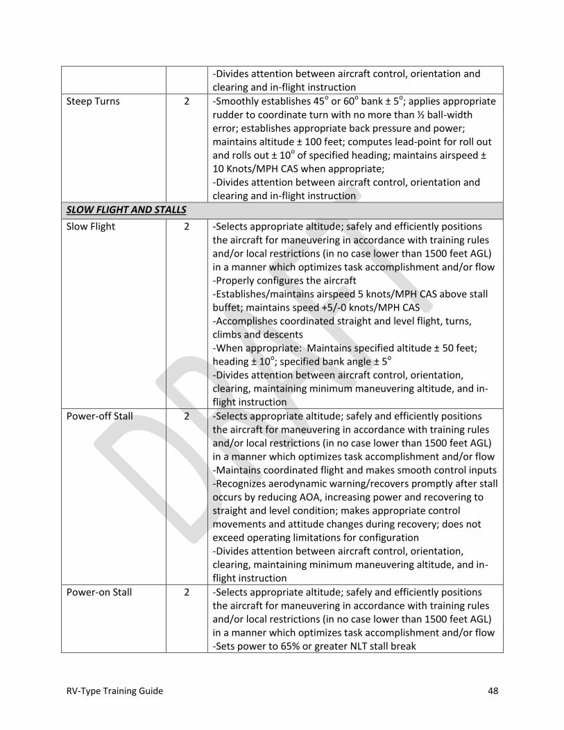
RV-Type Training Guide 48
-Divides attention between aircraft control, orientation and clearing and in-flight instruction
Steep Turns 2 -Smoothly establishes 45o or 60o bank ± 5o; applies appropriate rudder to coordinate turn with no more than ½ ball-width error; establishes appropriate back pressure and power; maintains altitude ± 100 feet; computes lead-point for roll out and rolls out ± 10o of specified heading; maintains airspeed ± 10 Knots/MPH CAS when appropriate; -Divides attention between aircraft control, orientation and clearing and in-flight instruction
SLOW FLIGHT AND STALLS
Slow Flight 2 -Selects appropriate altitude; safely and efficiently positions the aircraft for maneuvering in accordance with training rules and/or local restrictions (in no case lower than 1500 feet AGL) in a manner which optimizes task accomplishment and/or flow -Properly configures the aircraft -Establishes/maintains airspeed 5 knots/MPH CAS above stall buffet; maintains speed +5/-0 knots/MPH CAS -Accomplishes coordinated straight and level flight, turns, climbs and descents -When appropriate: Maintains specified altitude ± 50 feet; heading ± 10o; specified bank angle ± 5o -Divides attention between aircraft control, orientation, clearing, maintaining minimum maneuvering altitude, and in-flight instruction
Power-off Stall 2 -Selects appropriate altitude; safely and efficiently positions the aircraft for maneuvering in accordance with training rules and/or local restrictions (in no case lower than 1500 feet AGL) in a manner which optimizes task accomplishment and/or flow -Maintains coordinated flight and makes smooth control inputs -Recognizes aerodynamic warning/recovers promptly after stall occurs by reducing AOA, increasing power and recovering to straight and level condition; makes appropriate control movements and attitude changes during recovery; does not exceed operating limitations for configuration -Divides attention between aircraft control, orientation, clearing, maintaining minimum maneuvering altitude, and in-flight instruction
Power-on Stall 2 -Selects appropriate altitude; safely and efficiently positions the aircraft for maneuvering in accordance with training rules and/or local restrictions (in no case lower than 1500 feet AGL) in a manner which optimizes task accomplishment and/or flow -Sets power to 65% or greater NLT stall break
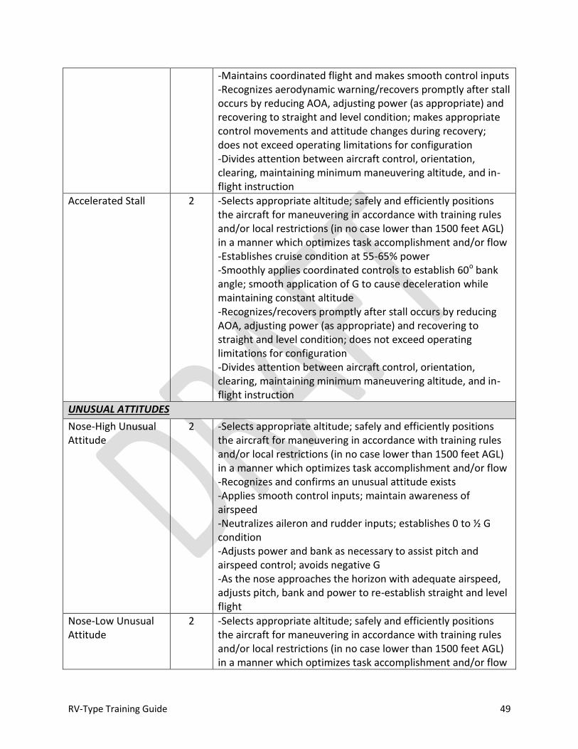
RV-Type Training Guide 49
-Maintains coordinated flight and makes smooth control inputs -Recognizes aerodynamic warning/recovers promptly after stall occurs by reducing AOA, adjusting power (as appropriate) and recovering to straight and level condition; makes appropriate control movements and attitude changes during recovery; does not exceed operating limitations for configuration -Divides attention between aircraft control, orientation, clearing, maintaining minimum maneuvering altitude, and in-flight instruction
Accelerated Stall 2 -Selects appropriate altitude; safely and efficiently positions the aircraft for maneuvering in accordance with training rules and/or local restrictions (in no case lower than 1500 feet AGL) in a manner which optimizes task accomplishment and/or flow -Establishes cruise condition at 55-65% power -Smoothly applies coordinated controls to establish 60o bank angle; smooth application of G to cause deceleration while maintaining constant altitude -Recognizes/recovers promptly after stall occurs by reducing AOA, adjusting power (as appropriate) and recovering to straight and level condition; does not exceed operating limitations for configuration -Divides attention between aircraft control, orientation, clearing, maintaining minimum maneuvering altitude, and in-flight instruction
UNUSUAL ATTITUDES
Nose-High Unusual Attitude
2 -Selects appropriate altitude; safely and efficiently positions the aircraft for maneuvering in accordance with training rules and/or local restrictions (in no case lower than 1500 feet AGL) in a manner which optimizes task accomplishment and/or flow -Recognizes and confirms an unusual attitude exists -Applies smooth control inputs; maintain awareness of airspeed -Neutralizes aileron and rudder inputs; establishes 0 to ½ G condition -Adjusts power and bank as necessary to assist pitch and airspeed control; avoids negative G -As the nose approaches the horizon with adequate airspeed, adjusts pitch, bank and power to re-establish straight and level flight
Nose-Low Unusual Attitude
2 -Selects appropriate altitude; safely and efficiently positions the aircraft for maneuvering in accordance with training rules and/or local restrictions (in no case lower than 1500 feet AGL) in a manner which optimizes task accomplishment and/or flow

RV-Type Training Guide 50
-Recognizes and confirms an unusual attitude exists -Applies smooth control inputs; maintains awareness of airspeed and adjusts power appropriately; avoids over G
CONFIDENCE MANEUVERS
Lazy-Eight / Wing-over
2 -Selects appropriate altitude; safely and efficiently positions the aircraft for maneuvering in accordance with training rules and/or local restrictions (in no case lower than 1500 feet AGL) in a manner which optimizes task accomplishment and/or flow -Establishes 55-65% cruise condition -Maintains constant pitch and roll rate throughout maneuver using smooth control inputs -Coordinates control inputs -Heading ± 15o from entry reference at 180o points -Airspeed ± 20 knots/MPH CAS (not to exceed VNO) from entry reference speed For maximum performance maneuvering: degrees of roll approximately equal to degrees of heading change (i.e., nose slicing through the horizon with 90o bank at 90o turn point). -Divides attention between aircraft control, orientation, clearing, maintaining minimum maneuvering altitude, and in-flight instruction
Chandelle
2 -Selects appropriate altitude; safely and efficiently positions the aircraft for maneuvering in accordance with training rules and/or local restrictions (in no case lower than 1500 feet AGL) in a manner which optimizes task accomplishment and/or flow -Establishes 55-65% cruise condition -Simultaneous application of power and smooth pitch and roll inputs to establish 45-60o bank by 45oturn point; maintains bank until 135o point -Coordinates control inputs -Completes roll out at 180o point ± 15o at speed slightly above stall -Divides attention between aircraft control, orientation, clearing, maintaining minimum maneuvering altitude, and in-flight instruction
AOA Recovery 2 -Understands and effectively instructs “Unload for Control” concept -Selects appropriate altitude; safely and efficiently positions the aircraft for maneuvering in accordance with training rules and/or local restrictions (in no case lower than 1500 feet AGL) in a manner which optimizes task accomplishment and/or flow -Smoothly retards the throttle to Idle-1500 RPM -Smoothly establishes and maintains 0 to ½ G condition with

RV-Type Training Guide 51
neutral controls -Coordinates recovery inputs -Avoids excessive airspeed build-up -Reestablishes straight and level flight -Divides attention between aircraft control, orientation, clearing, maintaining minimum maneuvering altitude, and in-flight instruction
Low AOA Aileron Roll
2 -Selects appropriate altitude; safely and efficiently positions the aircraft for maneuvering in accordance with training rules and/or local restrictions (in no case lower than 1500 feet AGL) in a manner which optimizes task accomplishment and/or flow -Smoothly establishes 45-60o pitch to 90 knots/100 MPH CAS -Smoothly establishes and maintains 0 to ½ G condition and rolls the aircraft through 360o as the nose tracks down -Coordinates recovery inputs -Avoids excessive airspeed build-up -Reestablishes straight and level flight -Divides attention between aircraft control, orientation, clearing, maintaining minimum maneuvering altitude, and in-flight instruction
Inverted Recovery 2 -Selects appropriate altitude; safely and efficiently positions the aircraft for maneuvering in accordance with training rules and/or local restrictions (in no case lower than 1500 feet AGL) in a manner which optimizes task accomplishment and/or flow -Smoothly establishes 60o pitch to 70 knots/80 MPH CAS -Smoothly establishes and maintains 0 to ½ G condition and rolls the aircraft through 180o to inverted; -Maintains inverted 0 to ½ G condition as the nose drops -Performs low AOA roll to upright as airspeed increases -Avoids excessive airspeed build-up -Reestablishes straight and level flight -Divides attention between aircraft control, orientation, clearing, maintaining minimum maneuvering altitude, and in-flight instruction
Deep Stall 2 -Selects appropriate altitude; safely and efficiently positions the aircraft for maneuvering in accordance with training rules and/or local restrictions (in no case lower than 3500 feet AGL) -Smoothly decelerates to a power off to a stalled condition, recognizes aerodynamic warning -Maintains sufficient AOA to sustain stalled condition -Recognizes yaw and smoothly and efficiently applies appropriate rudder to counter nose slice/wing drop -Recovers to a glide without use of power from nose-low condition without excessive airspeed build-up
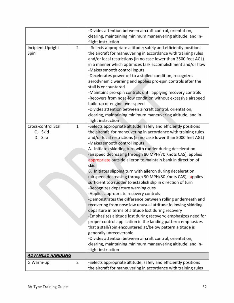
RV-Type Training Guide 52
-Divides attention between aircraft control, orientation, clearing, maintaining minimum maneuvering altitude, and in-flight instruction
Incipient Upright Spin
2 --Selects appropriate altitude; safely and efficiently positions the aircraft for maneuvering in accordance with training rules and/or local restrictions (in no case lower than 3500 feet AGL) in a manner which optimizes task accomplishment and/or flow -Makes smooth control inputs -Decelerates power off to a stalled condition, recognizes aerodynamic warning and applies pro-spin controls after the stall is encountered -Maintains pro-spin controls until applying recovery controls -Recovers from nose-low condition without excessive airspeed build-up or engine over-speed -Divides attention between aircraft control, orientation, clearing, maintaining minimum maneuvering altitude, and in-flight instruction
Cross-control Stall C. Skid D. Slip
1 -Selects appropriate altitude; safely and efficiently positions the aircraft for maneuvering in accordance with training rules and/or local restrictions (in no case lower than 5000 feet AGL) -Makes smooth control inputs A. Initiates skidding turn with rudder during deceleration (airspeed decreasing through 80 MPH/70 Knots CAS); applies appropriate outside aileron to maintain bank in direction of skid B. Initiates slipping turn with aileron during deceleration (airspeed decreasing through 90 MPH/80 Knots CAS); applies sufficient top rudder to establish slip in direction of turn -Recognizes departure warning cues -Applies appropriate recovery controls -Demonstrates the difference between rolling underneath and recovering from nose low unusual attitude following skidding departure in terms of altitude lost during recovery -Emphasizes altitude lost during recovery; emphasizes need for proper control application in the landing pattern; emphasizes that a stall/spin encountered at/below pattern altitude is generally unrecoverable -Divides attention between aircraft control, orientation, clearing, maintaining minimum maneuvering altitude, and in-flight instruction
ADVANCED HANDLING
G Warm-up 2 -Selects appropriate altitude; safely and efficiently positions the aircraft for maneuvering in accordance with training rules

RV-Type Training Guide 53
FARs and/or local restrictions in a manner which optimizes task accomplishment and/or flow -Establishes 130-140 knots/150-160 MPH CAS / 65% Power condition -Over-banks and smoothly applies 3 G’s for approximately 90o of heading change -Reverses turn direction with an unloaded roll while establishing 130-150 knots/150-170 MPH CAS -Smoothly applies 4 G’s for approximately 90o of heading change -Manages velocity vector throughout maneuver; avoids excessive speed build-up or accelerated stall -Divides attention between aircraft control, orientation, clearing, maintaining minimum maneuvering altitude, and in-flight instruction
Acceleration maneuver
2 -Selects appropriate altitude; safely and efficiently positions the aircraft for maneuvering in accordance with training rules FARs and/or local restrictions in a manner which optimizes task accomplishment and/or flow -Smoothly establishes 0 to ½ G condition -Avoids negative G, unintentional engine interruption -Manages velocity vector throughout maneuver; avoids excessive speed build-up -Divides attention between aircraft control, orientation, clearing, maintaining minimum maneuvering altitude, and in-flight instruction
Basic Roll 2 -Selects appropriate altitude; safely and efficiently positions the aircraft for maneuvering in accordance with training rules FARs and/or local restrictions in a manner which optimizes task accomplishment and/or flow -Establishes 125-150 knots/140-170 MPH CAS / 65-75% Power condition -Smoothly applies back stick to establish 20-30o nose up -Unloads to neutralize elevator input then applies smooth aileron input in desired direction of roll; maintains sufficient roll rate to ensure return to upright attitude no later than 20-30o nose low -Divides attention between aircraft control, orientation, clearing, maintaining minimum maneuvering altitude, and in-flight instruction
Loop 2 -Selects appropriate altitude; safely and efficiently positions the aircraft for maneuvering in accordance with training rules FARs and/or local restrictions in a manner which optimizes task accomplishment and/or flow
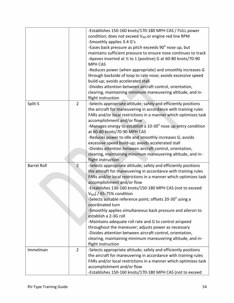
RV-Type Training Guide 54
-Establishes 150-160 knots/170-180 MPH CAS / FULL power condition; does not exceed VNO or engine red line RPM -Smoothly applies 3-4 G’s -Eases back pressure as pitch exceeds 90o nose up, but maintains sufficient pressure to ensure nose continues to track -Apexes inverted at ½ to 1 (positive) G at 60-80 knots/70-90 MPH CAS -Reduces power (when appropriate) and smoothly increases G through backside of loop to rate nose; avoids excessive speed build-up; avoids accelerated stall -Divides attention between aircraft control, orientation, clearing, maintaining minimum maneuvering altitude, and in-flight instruction
Split-S 2 -Selects appropriate altitude; safely and efficiently positions the aircraft for maneuvering in accordance with training rules FARs and/or local restrictions in a manner which optimizes task accomplishment and/or flow -Manages energy to establish a 10-30o nose up entry condition at 60-80 knots/70-90 MPH CAS -Reduces power to idle and smoothly increases G; avoids excessive speed build-up; avoids accelerated stall -Divides attention between aircraft control, orientation, clearing, maintaining minimum maneuvering altitude, and in-flight instruction
Barrel Roll 2 -Selects appropriate altitude; safely and efficiently positions the aircraft for maneuvering in accordance with training rules FARs and/or local restrictions in a manner which optimizes task accomplishment and/or flow -Establishes 130-160 knots/150-180 MPH CAS (not to exceed VNO) / 65-75% condition -Selects suitable reference point; offsets 20-30o using a coordinated turn -Smoothly applies simultaneous back pressure and aileron to establish a 2-3G roll -Maintains adequate roll rate and G to control airspeed throughout the maneuver; adjusts power as necessary -Divides attention between aircraft control, orientation, clearing, maintaining minimum maneuvering altitude, and in-flight instruction
Immelman 2 -Selects appropriate altitude; safely and efficiently positions the aircraft for maneuvering in accordance with training rules FARs and/or local restrictions in a manner which optimizes task accomplishment and/or flow -Establishes 150-160 knots/170-180 MPH CAS (not to exceed
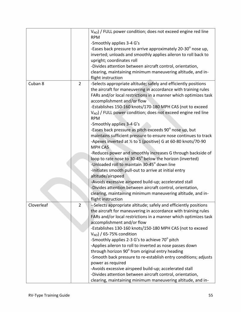
RV-Type Training Guide 55
VNO) / FULL power condition; does not exceed engine red line RPM -Smoothly applies 3-4 G’s -Eases back pressure to arrive approximately 20-30o nose up, inverted; unloads and smoothly applies aileron to roll back to upright; coordinates roll -Divides attention between aircraft control, orientation, clearing, maintaining minimum maneuvering altitude, and in-flight instruction
Cuban 8 2 -Selects appropriate altitude; safely and efficiently positions the aircraft for maneuvering in accordance with training rules FARs and/or local restrictions in a manner which optimizes task accomplishment and/or flow -Establishes 150-160 knots/170-180 MPH CAS (not to exceed VNO) / FULL power condition; does not exceed engine red line RPM -Smoothly applies 3-4 G’s -Eases back pressure as pitch exceeds 90o nose up, but maintains sufficient pressure to ensure nose continues to track -Apexes inverted at ½ to 1 (positive) G at 60-80 knots/70-90 MPH CAS -Reduces power and smoothly increases G through backside of loop to rate nose to 30-45o below the horizon (inverted) -Unloaded roll to maintain 30-45o down line -Initiates smooth pull-out to arrive at initial entry altitude/airspeed -Avoids excessive airspeed build-up; accelerated stall -Divides attention between aircraft control, orientation, clearing, maintaining minimum maneuvering altitude, and in-flight instruction
Cloverleaf 2 --Selects appropriate altitude; safely and efficiently positions the aircraft for maneuvering in accordance with training rules FARs and/or local restrictions in a manner which optimizes task accomplishment and/or flow -Establishes 130-160 knots/150-180 MPH CAS (not to exceed VNO) / 65-75% condition -Smoothly applies 2-3 G’s to achieve 70o pitch -Applies aileron to roll to inverted as nose passes down through horizon 90o from original entry heading -Smooth back pressure to re-establish entry conditions; adjusts power as required -Avoids excessive airspeed build-up; accelerated stall -Divides attention between aircraft control, orientation, clearing, maintaining minimum maneuvering altitude, and in-
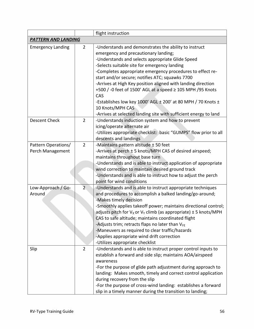
RV-Type Training Guide 56
flight instruction
PATTERN AND LANDING
Emergency Landing 2 -Understands and demonstrates the ability to instruct emergency and precautionary landing; -Understands and selects appropriate Glide Speed -Selects suitable site for emergency landing -Completes appropriate emergency procedures to effect re-start and/or secure; notifies ATC; squawks 7700 -Arrives at High Key position aligned with landing direction +500 / -0 feet of 1500’ AGL at a speed ≥ 105 MPH /95 Knots CAS -Establishes low key 1000’ AGL ± 200’ at 80 MPH / 70 Knots ± 10 Knots/MPH CAS -Arrives at selected landing site with sufficient energy to land
Descent Check 2 -Understands induction system and how to prevent icing/operate alternate air -Utilizes appropriate checklist: basic “GUMPS” flow prior to all descents and landings
Pattern Operations/ Perch Management
2 -Maintains pattern altitude ± 50 feet -Arrives at perch ± 5 knots/MPH CAS of desired airspeed; maintains throughout base turn -Understands and is able to instruct application of appropriate wind correction to maintain desired ground track -Understands and is able to instruct how to adjust the perch point for wind conditions
Low-Approach / Go-Around
2 -Understands and is able to instruct appropriate techniques and procedures to accomplish a balked landing/go-around; -Makes timely decision -Smoothly applies takeoff power; maintains directional control; adjusts pitch for VX or VY climb (as appropriate) ± 5 knots/MPH CAS to safe altitude; maintains coordinated flight -Adjusts trim; retracts flaps no later than VFE -Maneuvers as required to clear traffic/hazards -Applies appropriate wind drift correction -Utilizes appropriate checklist
Slip 2 -Understands and is able to instruct proper control inputs to establish a forward and side slip; maintains AOA/airspeed awareness -For the purpose of glide path adjustment during approach to landing: Makes smooth, timely and correct control application during recovery from the slip -For the purpose of cross-wind landing: establishes a forward slip in a timely manner during the transition to landing;
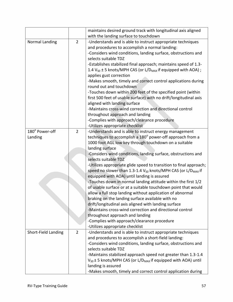
RV-Type Training Guide 57
maintains desired ground track with longitudinal axis aligned with the landing surface to touchdown
Normal Landing 2 -Understands and is able to instruct appropriate techniques and procedures to accomplish a normal landing: -Considers wind conditions, landing surface, obstructions and selects suitable TDZ -Establishes stabilized final approach; maintains speed of 1.3-1.4 VS0 ± 5 knots/MPH CAS (or L/DMAX if equipped with AOA) ; applies gust correction -Makes smooth, timely and correct control applications during round out and touchdown -Touches down within 200 feet of the specified point (within first 500 feet of usable surface) with no drift/longitudinal axis aligned with landing surface -Maintains cross-wind correction and directional control throughout approach and landing -Complies with approach/clearance procedure -Utilizes appropriate checklist
180o Power-off Landing
2 -Understands and is able to instruct energy management techniques to accomplish a 180o power-off approach from a 1000 foot AGL low key through touchdown on a suitable landing surface -Considers wind conditions, landing surface, obstructions and selects suitable TDZ -Utilizes appropriate glide speed to transition to final approach; speed no slower than 1.3-1.4 VS0 knots/MPH CAS (or L/DMAX if equipped with AOA) until landing is assured -Touches down in normal landing attitude within the first 1/2 of usable surface or at a suitable touchdown point that would allow a full stop landing without application of abnormal braking on the landing surface available with no drift/longitudinal axis aligned with landing surface -Maintains cross-wind correction and directional control throughout approach and landing -Complies with approach/clearance procedure -Utilizes appropriate checklist
Short-Field Landing 2 -Understands and is able to instruct appropriate techniques and procedures to accomplish a short-field landing: -Considers wind conditions, landing surface, obstructions and selects suitable TDZ -Maintains stabilized approach speed not greater than 1.3-1.4 VS0 ± 5 knots/MPH CAS (or L/DMAX if equipped with AOA) until landing is assured -Makes smooth, timely and correct control application during

RV-Type Training Guide 58
the round out and touchdown -Touches down smoothly at minimum control airspeed at or within 200 feet of planned TDZ with no side drift, minimum float and longitudinal axis aligned with landing path -Maintains cross-wind correction and directional control throughout the approach and landing sequence -Applies brakes and flight controls as necessary to stop in the shortest distance consistent with safety -Utilizes appropriate checklist
Soft-Field Landing 2 -Understands and is able to instruct appropriate techniques and procedures to accomplish a soft-field landing: -Considers wind conditions, landing surface, obstructions and selects suitable TDZ -Maintains stabilized approach speed not greater than 1.3-1.4 VS0 ± 5 knots/MPH CAS (or L/DMAX if equipped with AOA) until landing is assured -Makes smooth, timely and correct control application during the round out and touchdown -Touches down softly with no drift and longitudinal axis aligned with landing path -Maintains cross-wind correction and directional control throughout the approach and landing sequence -Utilizes proper flight controls, speed and power to taxi on the soft surface -Utilizes appropriate checklist
AFTER LANDING
After landing, parking and securing
2 -Maintains directional control -Observes markings/procedures/clearance(s) -Parks in appropriate area; considers safety of airplane, persons and property on the ground -Utilizes appropriate checklist -Understands and is able to instruct techniques for moving the airplane after shutdown -Able to instruct proper conduct of post-flight inspection and offer techniques to properly secure the aircraft
Servicing 2 -Understands and is able to instruct how to fuel the aircraft: -Properly ground the airplane during refueling operations; understands how to remove, adjust and secure gas caps; exhibits methodology for determining fuel load for less than full tanks; knows location of all fuel drains and is able to drain and inspect fuel from all points -Understands the proper type/weight and how to service oil to the engine sump; able to determine oil level

RV-Type Training Guide 59
AIRMANSHIP
Clearing / Visual Look-out
2 -Utilizes proper scanning techniques -Maneuvers as required to ensure flight path is clear of traffic -Maintains situational awareness of other aircraft operating on frequency/sharing the traffic pattern -Understands and applies right of way rules
Fuel Management 2 -Determines fuel requirements and ensures proper fuel load for the conduct of the flight; ensures sufficient fuel reserve at all times -Monitors fuel level throughout the flight -Computes appropriate BINGO fuel -Maintains fuel levels sufficient for lateral balance
Airmanship 2 -Understands aircraft capabilities and limitations -Able to navigate; maintains orientation -Adheres to training rules, procedures and regulations, safely positions the aircraft for maneuvering -Utilizes resources effectively -Recognizes fatigue and degraded performance -Manages cockpit workload effectively; prioritizes; does not rush
Judgment (ORM/ADM)
2 -Identifies and is able to instruct how to identify potential risks/hazards, analyzes or develop controls, and making control decisions and monitors results -Understands pilot capabilities: assists the upgrading pilot with establishing and adhering to appropriate personal limitations -Applies and is able to instruct how to apply appropriate prioritization to ensure safety -Familiar with EAB safety considerations and mishap statistics
INSTRUCTIONAL ABILITY
Ground Instruction 2 -Able to develop and conduct effective briefing; offers suitable techniques for accomplishment of various tasks -Effectively utilizes time available for the conduct of briefing and debriefing -Effectively utilizes visual aids during the conduct of brief and debrief -Familiar with the learning process and barriers to learning; recognizes student saturation -Able to accurately reconstruct flight during debrief and effectively assist upgrading pilot with proper understanding or familiarity with various tasks; evaluate and critique performance; develop upgrading pilot potential -Able to effectively answer questions and utilize appropriate reference material; demonstrates thorough understanding of
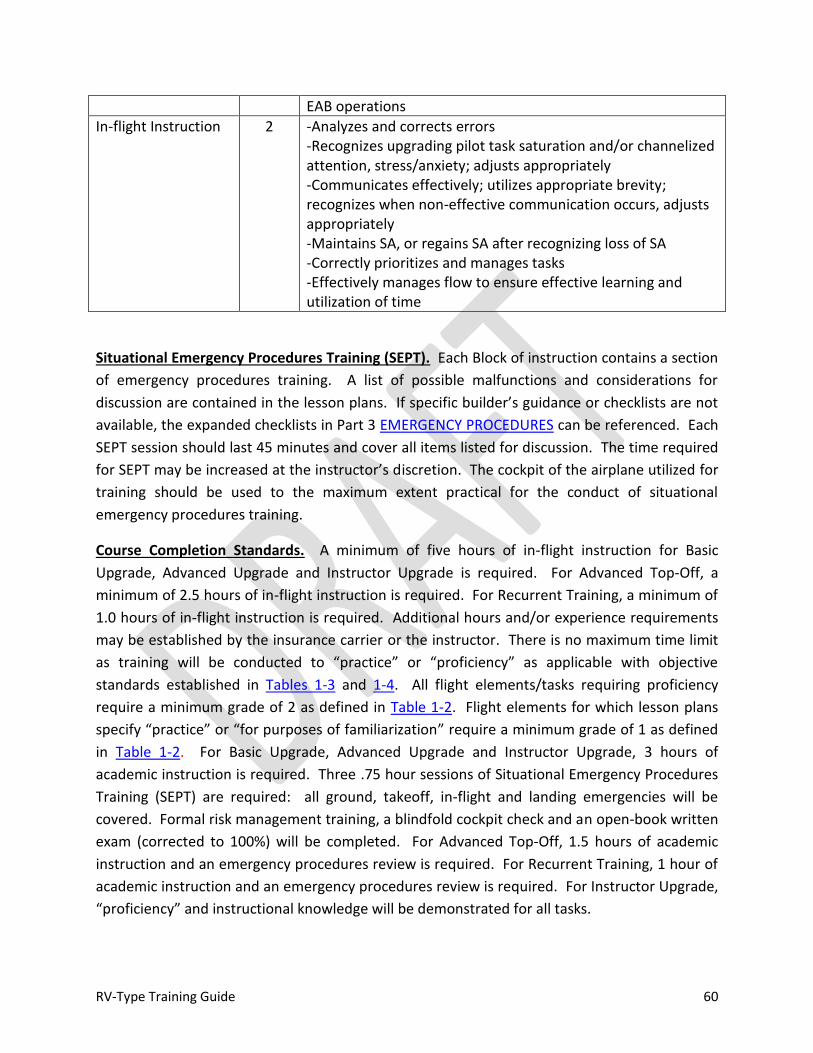
RV-Type Training Guide 60
EAB operations
In-flight Instruction 2 -Analyzes and corrects errors -Recognizes upgrading pilot task saturation and/or channelized attention, stress/anxiety; adjusts appropriately -Communicates effectively; utilizes appropriate brevity; recognizes when non-effective communication occurs, adjusts appropriately -Maintains SA, or regains SA after recognizing loss of SA -Correctly prioritizes and manages tasks -Effectively manages flow to ensure effective learning and utilization of time
Situational Emergency Procedures Training (SEPT). Each Block of instruction contains a section
of emergency procedures training. A list of possible malfunctions and considerations for
discussion are contained in the lesson plans. If specific builder’s guidance or checklists are not
available, the expanded checklists in Part 3 EMERGENCY PROCEDURES can be referenced. Each
SEPT session should last 45 minutes and cover all items listed for discussion. The time required
for SEPT may be increased at the instructor’s discretion. The cockpit of the airplane utilized for
training should be used to the maximum extent practical for the conduct of situational
emergency procedures training.
Course Completion Standards. A minimum of five hours of in-flight instruction for Basic
Upgrade, Advanced Upgrade and Instructor Upgrade is required. For Advanced Top-Off, a
minimum of 2.5 hours of in-flight instruction is required. For Recurrent Training, a minimum of
1.0 hours of in-flight instruction is required. Additional hours and/or experience requirements
may be established by the insurance carrier or the instructor. There is no maximum time limit
as training will be conducted to “practice” or “proficiency” as applicable with objective
standards established in Tables 1-3 and 1-4. All flight elements/tasks requiring proficiency
require a minimum grade of 2 as defined in Table 1-2. Flight elements for which lesson plans
specify “practice” or “for purposes of familiarization” require a minimum grade of 1 as defined
in Table 1-2. For Basic Upgrade, Advanced Upgrade and Instructor Upgrade, 3 hours of
academic instruction is required. Three .75 hour sessions of Situational Emergency Procedures
Training (SEPT) are required: all ground, takeoff, in-flight and landing emergencies will be
covered. Formal risk management training, a blindfold cockpit check and an open-book written
exam (corrected to 100%) will be completed. For Advanced Top-Off, 1.5 hours of academic
instruction and an emergency procedures review is required. For Recurrent Training, 1 hour of
academic instruction and an emergency procedures review is required. For Instructor Upgrade,
“proficiency” and instructional knowledge will be demonstrated for all tasks.

RV-Type Training Guide 61
Note
All tracks of instruction meet requirements for completion of a flight review in accordance with FAR 61.57.

RV-Type Training Guide 62
RV-Type Fuel Considerations
-Fuel consumption can vary widely from data in the engine operator’s manual. Due to
variance in construction and power plant size and configurations, it is difficult to establish a
baseline ROT that would apply to all RV-type airplanes. Furthermore, even airplanes with
nearly identical characteristics can vary in consumption (e.g., carburetor out of adjustment,
etc.). It is imperative to obtain accurate fuel consumption data for the airplane flown. If
this has not been provided by the builder, it must be obtained through research and flight
test. Fuel flow devices must be properly calibrated to provide accurate information.
Calibration must be confirmed by flight test.
-Failure to know fuel consumption rates for the airplane operated is just as dangerous as
not checking fuel on-board before flight. The exact amount of fuel on board must be known
and confirmed prior to engine start.
-For certified airplanes, the fuel gauges are required to read accurately only when the tanks
are completely full OR empty. Although a sound practice for calibrating gauges, keep in
mind that certification standards do not apply to EAB aircraft, so even this basic assumption
cannot be made. Fuel gauge accuracy must be confirmed by proper calibration and test.
-For a normally aspirated 320 cubic inch engine with a compression ratio of 8.5:1 or less
equipped with an aviation carburetor, fuel flow can exceed 13 GPH at high power, with a
significant increase in fuel flow at power settings greater than 75% power. For a normally
aspirated 360 cubic inch engine with a compression ratio of 8.5:1 or less equipped with an
aviation carburetor, fuel flow can exceed 17 GPH at high power, with a significant increase
in fuel flow at power settings greater than 75% power. For leaned operation below 70%
power, aircraft test and engine manufacturer’s data should be consulted to determine
nominal fuel flow rates.
- For best power leaned operation ≤ 65% power, a nominal fuel flow of approximately 10
GPH should be anticipated (i.e., 1 gallon per 1/10 hour of engine operation), unless specific
information regarding power setting and fuel consumption is available for the airplane
operated.
-Unusable Fuel. Each RV-type airplane will have a certain amount of unusable fuel. The
exact amount can only be determined by testing. If test data is not available for the
airplane being operated, it is recommended that it be ASSUMED that a MINUMUM of 1
gallon per side is unusable.
-Fuel Reserve. A minimum 45 minute reserve should be utilized during training operations.
Assuming a 1 gallon unusable fuel quantity, O-320 powered airplanes should land with a
minimum of 7 gallons on board, and O-360 powered airplanes should land with a minimum
of 9 gallons on board (assuming a nominal cruise fuel flow rate of 8 GPH for an O-320
equipped airplane and 10 GPH for an O-360 equipped airplane). Specific values should be
computed based on manufacturer’s/builder’s data (confirmed by flight test) for the airplane
operated.
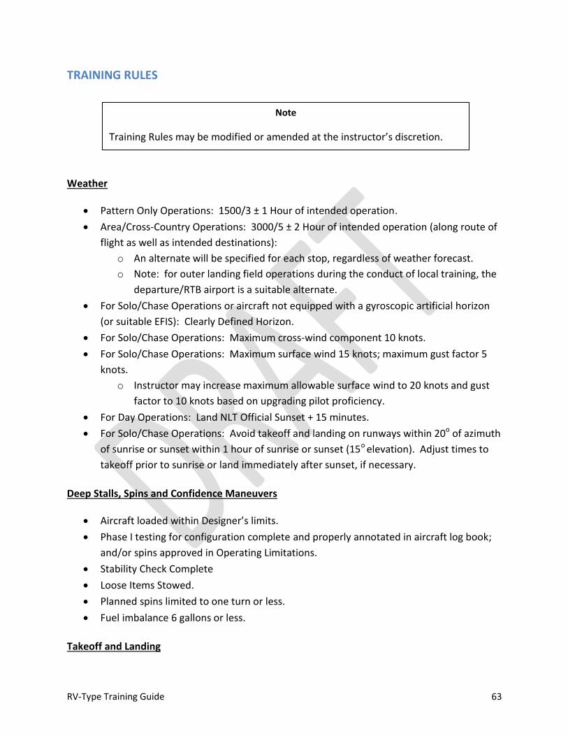
RV-Type Training Guide 63
TRAINING RULES
Weather
Pattern Only Operations: 1500/3 ± 1 Hour of intended operation.
Area/Cross-Country Operations: 3000/5 ± 2 Hour of intended operation (along route of
flight as well as intended destinations):
o An alternate will be specified for each stop, regardless of weather forecast.
o Note: for outer landing field operations during the conduct of local training, the
departure/RTB airport is a suitable alternate.
For Solo/Chase Operations or aircraft not equipped with a gyroscopic artificial horizon
(or suitable EFIS): Clearly Defined Horizon.
For Solo/Chase Operations: Maximum cross-wind component 10 knots.
For Solo/Chase Operations: Maximum surface wind 15 knots; maximum gust factor 5
knots.
o Instructor may increase maximum allowable surface wind to 20 knots and gust
factor to 10 knots based on upgrading pilot proficiency.
For Day Operations: Land NLT Official Sunset + 15 minutes.
For Solo/Chase Operations: Avoid takeoff and landing on runways within 20o of azimuth
of sunrise or sunset within 1 hour of sunrise or sunset (15o elevation). Adjust times to
takeoff prior to sunrise or land immediately after sunset, if necessary.
Deep Stalls, Spins and Confidence Maneuvers
Aircraft loaded within Designer’s limits.
Phase I testing for configuration complete and properly annotated in aircraft log book;
and/or spins approved in Operating Limitations.
Stability Check Complete
Loose Items Stowed.
Planned spins limited to one turn or less.
Fuel imbalance 6 gallons or less.
Takeoff and Landing
Note
Training Rules may be modified or amended at the instructor’s discretion.
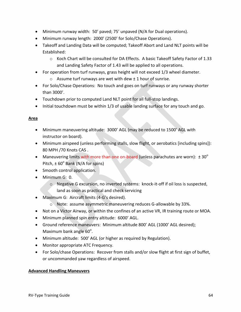
RV-Type Training Guide 64
Minimum runway width: 50’ paved; 75’ unpaved (N/A for Dual operations).
Minimum runway length: 2000’ (2500’ for Solo/Chase Operations).
Takeoff and Landing Data will be computed; Takeoff Abort and Land NLT points will be
Established:
o Koch Chart will be consulted for DA Effects. A basic Takeoff Safety Factor of 1.33
and Landing Safety Factor of 1.43 will be applied to all operations.
For operation from turf runways, grass height will not exceed 1/3 wheel diameter.
o Assume turf runways are wet with dew ± 1 hour of sunrise.
For Solo/Chase Operations: No touch and goes on turf runways or any runway shorter
than 3000’.
Touchdown prior to computed Land NLT point for all full-stop landings.
Initial touchdown must be within 1/3 of usable landing surface for any touch and go.
Area
Minimum maneuvering altitude: 3000’ AGL (may be reduced to 1500’ AGL with
instructor on board).
Minimum airspeed (unless performing stalls, slow flight, or aerobatics [including spins]):
80 MPH /70 Knots CAS .
Maneuvering limits with more than one on-board (unless parachutes are worn): ± 30o
Pitch, ± 60o Bank (N/A for spins)
Smooth control application.
Minimum G: 0.
o Negative G excursion, no inverted systems: knock-it-off if oil loss is suspected,
land as soon as practical and check servicing
Maximum G: Aircraft limits (4-G’s desired).
o Note: assume asymmetric maneuvering reduces G-allowable by 33%.
Not on a Victor Airway, or within the confines of an active VR, IR training route or MOA.
Minimum planned spin entry altitude: 6000’ AGL.
Ground reference maneuvers: Minimum altitude 800’ AGL (1000’ AGL desired);
Maximum bank angle 60o.
Minimum altitude: 500’ AGL (or higher as required by Regulation).
Monitor appropriate ATC Frequency.
For Solo/chase Operations: Recover from stalls and/or slow flight at first sign of buffet,
or uncommanded yaw regardless of airspeed.
Advanced Handling Maneuvers

RV-Type Training Guide 65
IAW Operating Limitations
Aircraft loaded IAW designer’s limitations for aerobatic flight
3000’ AGL maneuvering floor
Parachutes will be worn
Stability Check Complete
Prohibited Maneuvers
Intentional tail slide
Snap maneuvers performed at speeds greater than asymmetric VA
Negative G maneuvering, including inverted spins
Out-of-Control
Unless planned, initiate recovery (Unload for Control) at first sign of departure: Buffet;
wing rock/drop; nose slice or nose rise.
Recovery: Ailerons neutral; Unload for Control (0 – 1/2G); Rudder (as required)
Opposite Yaw
Aircraft is no longer out-of-control when unloaded and airspeed is passing 100 MPH / 90
Knots CAS
Pattern Operations
A cockpit takeoff flow check will be completed before beginning all takeoff rolls.
A cockpit landing (“GUMPS”) flow check will be completed prior to all landings.
Minimum pattern speed: ON SPEED and/or 80 MPH/75 Knots CAS (or 1.4 VS, whichever
is greater) until in a landing configuration on final approach.
Add 5 Knots/MPH to approach speeds for gusty conditions (or ½ reported gust velocity,
whichever is less).
For non-towered airports, minimum over-flight altitude 500’ above specified pattern
altitude or 1500’ AGL, whichever is less.
Fuel
Minimum fuel required for takeoff at the beginning of any flight: 2 hours (unless
precluded by weight and balance requirements).
Minimum fuel: 45 Minutes.
Planning FF and flight time limits based on actual fuel on board: calculated and
understood.

RV-Type Training Guide 66
Equipment
Dual flashlights required for night operations.
Spare batteries on board for all battery operated equipment.
For Solo/Chase Operations: Upgrading pilot will carry a cell phone.
For Solo/Chase Operations: Upgrading pilot will carry a GPS for all non-local (cross-
country) operations.
o Note: For the purposes of this section, outer landing field pattern work does not
constitute cross-country operation.
Minimum Bail-out Altitude
Controlled: NLT 1500 feet AGL
Out-of-Control: NLT 2500 feet AGL
Human Factors
Task saturation / Prioritization
Channelized attention
Fatigue
Time pressure
One-way decision gates
Bad communication
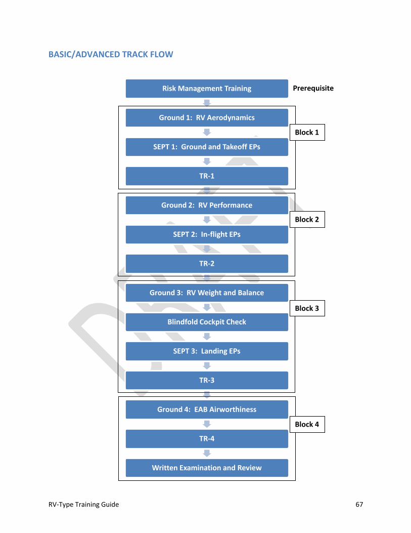
RV-Type Training Guide 67
BASIC/ADVANCED TRACK FLOW
Risk Management Training
Ground 1: RV Aerodynamics
SEPT 1: Ground and Takeoff EPs
TR-1
Ground 2: RV Performance
SEPT 2: In-flight EPs
TR-2
Ground 3: RV Weight and Balance
Blindfold Cockpit Check
SEPT 3: Landing EPs
TR-3
Ground 4: EAB Airworthiness
TR-4
Written Examination and Review
Block 1
Block 2
Block 3
Block 4
Prerequisite
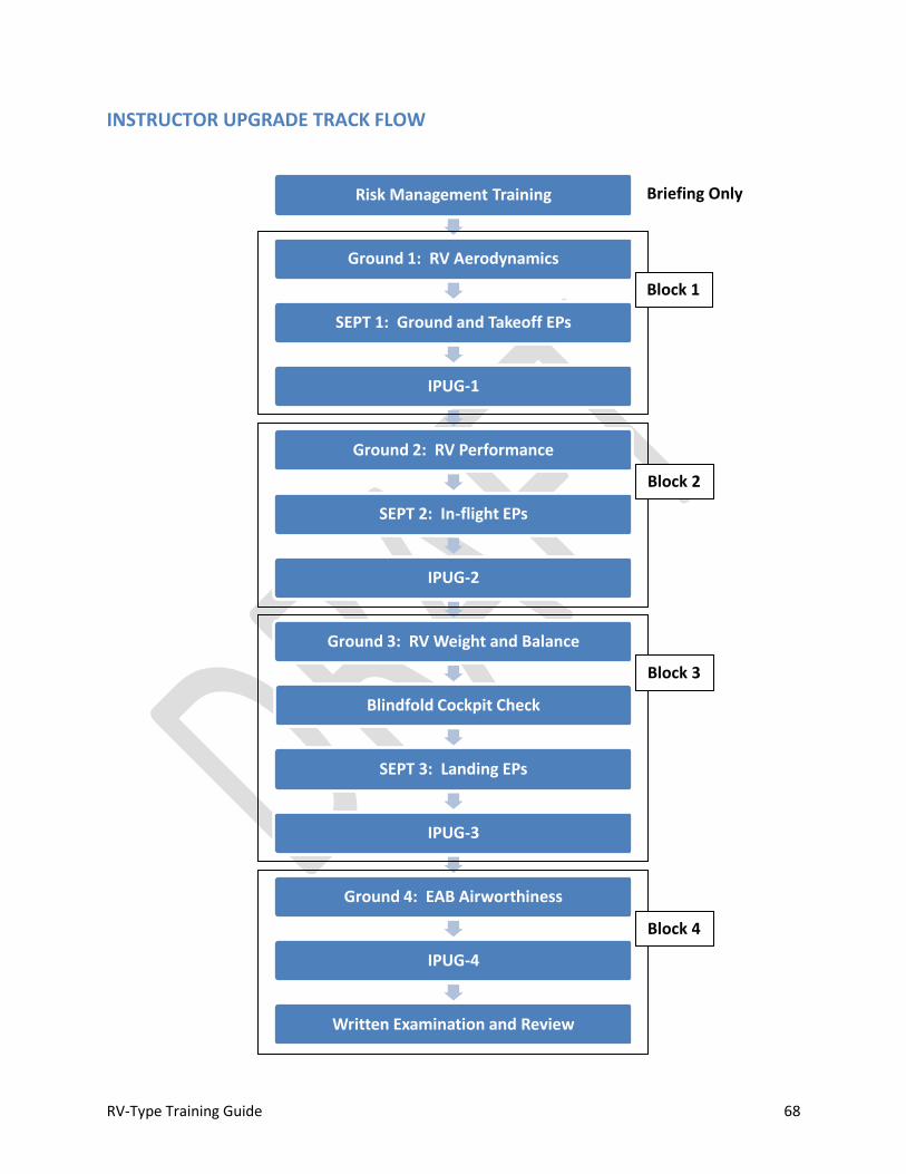
RV-Type Training Guide 68
INSTRUCTOR UPGRADE TRACK FLOW
Risk Management Training
Ground 1: RV Aerodynamics
SEPT 1: Ground and Takeoff EPs
IPUG-1
Ground 2: RV Performance
SEPT 2: In-flight EPs
IPUG-2
Ground 3: RV Weight and Balance
Blindfold Cockpit Check
SEPT 3: Landing EPs
IPUG-3
Ground 4: EAB Airworthiness
IPUG-4
Written Examination and Review
Block 1
Briefing Only
Block 2
Block 3
Block 4
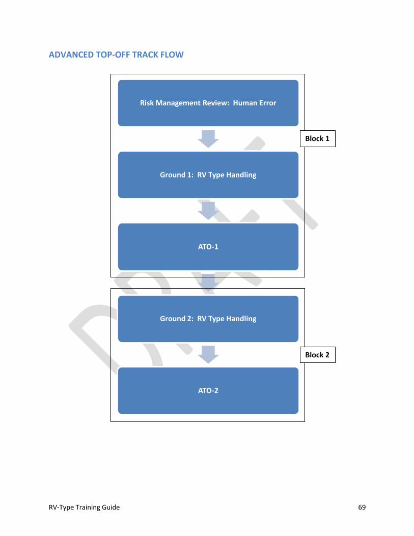
RV-Type Training Guide 69
ADVANCED TOP-OFF TRACK FLOW
Risk Management Review: Human Error
Ground 1: RV Type Handling
ATO-1
Ground 2: RV Type Handling
ATO-2
Block 1
Block 2
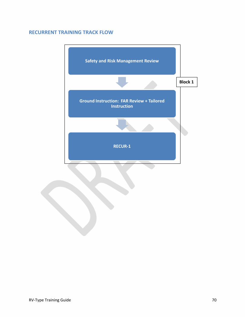
RV-Type Training Guide 70
RECURRENT TRAINING TRACK FLOW
Safety and Risk Management Review
Ground Instruction: FAR Review + Tailored Instruction
RECUR-1
Block 1
RV-Type Training Guide 71
Part 2: Lesson Plans and Briefing Guides OPERATIONAL RISK MANAGMENT
Risk 101
-Risk is insidious
-Unmanaged risk becomes unacceptable
-SURVEILLANCE is the key
-Look for risk: doesn’t jump out at you; but once identified, do something!
-Manage those Risks
-Usually something simple: get an updated weather brief, service fuel,
etc.
80-85% of all mishaps are result of risk management failure
-Flying training emphasizes physical skill
-We don’t really teach risk management
-We tell stories
-Establish rules; some are “written in blood”
-Make up sayings: “3 most useless things in aviation are altitude above you,
runway behind you and air in your fuel tanks, etc.”
-We learn two ways: from experience or mistakes/situations of others
-Bottom line: we haven’t done a good job of teaching risk management as a skill
We learn mostly through trial and error
Note
The information in this briefing outline has been adopted from the King Aviation School’s “Practical Risk Management” Course and is provided for reference. It is based on discussion contained in Chapter 17 (Aeronautical Decision Making) of the Pilot’s Handbook of Aeronautical Knowledge (FAA-H-8083-25A). Course requirements include formal risk management training if the upgrading pilot has not already completed such training (e.g., military, airlines, etc.). This outline is intended to provide a review for guided discussion, when required. The instructor will review basic risk management principles with the upgrading pilot prior to beginning Block 1 training.
The information in this briefing supports all tracks of training.
RV-Type Training Guide 72
-We are exposed to risk; if we make it, we evaluate after the fact
-Not too bad? Risk becomes acceptable BUT IT COULD HAVE JUST BEEN LUCK!
-Can lead to “normalization of deviance” if you “get away with it”
-Bottom line: you get the test first, then the lesson
Ugly Facts
-EXPERIENCE CAN’T PREPARE YOU FOR UNANTICIPATED RISK
-As a rule, pilot’s underestimate consequences
-Risk is vague/indefinite
-We do a poor job of estimating odds
-Benefits are specific/tangible…e.g., we get there, we land, etc.
-Bottom line: the human animal doesn’t do a good job of making decisions when the
risks are vague and the benefit is specific
We are the enemy
-Pilot psychology works against us
-Goal oriented
-Self-confident
-Sense of invulnerability
-Achiever
-Meets a challenge; effort as required to get the job done; commitment
and competence
-This behavior becomes self-reinforcing! The more successful we are, the
more we believe that we really ARE that good. This leads to sense of
invulnerability.
-Smart people do dumb things
-Fact: EVERYONE makes mistakes (regularly), even dumb ones, exacerbated
by fatigue
-We get impatient when things don’t go as planned
-Low tolerance for mistakes of others: e.g., ATC, other aircraft in the pattern,
etc.
-You can’t control buffoonery, but you CAN CONTROL THE WAY YOU REACT TO
IT!
-Rule #1: It does no good to get angry in the cockpit
-If you’re in a hurry, it’s probably a good time to slow down
-Discipline required
-You need gas as well; it’s hard to be patient if the fuel gauge is bumping
up against the “E”
RV-Type Training Guide 73
More Ugly Facts
-Goal oriented = Risk tolerant
-Question: Do you HAVE to do this NOW (this hour, today, etc.)?
-Experienced MIGHT = Risk tolerant
-“I’ve got 1000 hours of high performance time, I can handle this light
plane…even though I’ve only got three hours of tail wheel time”
-Risk tolerance
-Distorts risk evaluation
-Mission accomplishment over risk management
-Working alone? Much easier to risk your own life; but remember, your family
is ALWAYS flying with you!
-WE are the risk, it’s how we REACT to external factors that manages risk.
-Experts make as many mistakes as novices; the difference is that experts catch their
mistakes.
Risk Mitigation
-Rules and Regulations help: establish a simple decision matrix
-How do you get help with go / no-go decision?
-Online resources (Weather/NOTAMs/Flight Planning Tools)
-Fellow pilots
-Do you have a mentor?
-Basic risk mitigation checklist: PAVE mnemonic
-Pilot: Are you ready?
-Aircraft: Is the airplane ready?
-enVironment: Is the environment suitable?
-External pressure
-Application: look for risks in each area—if risks pop up in two or more areas, time to
think about Plan B…
Psychology
-Easy to critique others, especially ex post facto
-Reviewing mishaps helps us “learn from the mistakes of others”
-Key error/omission/malfunction tends to jump out of a review of a mishap
chain, yet a competent aviator failed to note this real-time…
-It’s difficult to pick out risk factors real-time for ourselves
-Need to identify risk and manage
-Minimums for each category
-Regulations don’t cover every contingency—they are designed to be
flexible

RV-Type Training Guide 74
-Personal skill sets/readiness varies from day to day
-On any given day, every pilot has to establish their own personal
minimums
Pilot: I’M SAFE Checklist
-Illness
-How “under the weather” are you?
-Under pressure to not be the weak link?
-Medication
-If there is a doubt, there is no doubt: consult AME
-Stress
-For some pilots, flying is stress relief; if you can’t decouple stress, don’t strap
in
-Alcohol
-8-hour rule vs. reality
-Fatigue/Food
-Motor/cognitive skills critically affected by fatigue
-Emotion
-Rule #1: It does no good to get angry in the cockpit
Aircraft
-Basic Airworthiness and servicing
-Required inspections complied with
-Non-scheduled maintenance status?
-Are you “ramp check” proof?
-EXACT amount of CLEAN fuel on board
-EXACT amount of oil in the engine sump
-Preflight inspection
-“RVism” Wheel and brake condition: what can you see with the wheel
pants installed?
-Unoccupied cockpit/seat: everything secure?
-Minimum equipment
-“Old Man” disease: tendency to do more with less, i.e., comfortable
accepting a less than perfect airplane
-That’s O.K. and a benefit of experience--JUST KNOW THAT BY
ACCEPTING MINIMUM EQUIPMENT, YOU’VE FLAGED ANOTHER RISK
CATEGORY
-Situation dependent
-Day VFR vs. Night IFR

RV-Type Training Guide 75
-Configuration: it’s experimental man!
-Has something been changed? Has it been tested?
-Sanity check: 43-13 compliant?
-Mentor? A&P familiar with EAB
Environment
-Biggest factor: WEATHER
-Different than forecast
-Unanticipated winds aloft/sheer affecting pattern operations
-Airfield
-Runway status/condition
-Cross-wind
-Approach aids?
-Airspace
-TFR?
-Terrain
-Off-station (out base) operations
-Away from the home ‘drome! Have you done your homework?
External Pressure
-Always there in the background: affects EVERYTHING we do
-Causes you to ignore other risk factors: clouds your judgment
-Time pressure
-Pilots are their own worst enemy; good ones know when it’s time to slow
down and get their faster
-Build yourself some room: you can usually recover from “too early”
-Peer pressure
-Mission Accomplishment
Pre-flight Decision Time
-Risk factors are cumulative
-Insidious
-If you have issues in two or more areas, flex to Plan B or consider an abort
-PAVE Categories: Pilot; Aircraft; environment; External Pressure
-Bottom line: This is the math part. Use the “accident chain” analogy, changing one or
two things will make a critical difference.
Real-time Risk Management: How to monitor risk during flight
-Utilize all available resources
-FSS
RV-Type Training Guide 76
-ATC
-Avionics: ADS-B in, XM Weather, etc.
-Warning: Latency of display! Need to be able to know what you’re
looking at. View out the window ALWAYS trumps the internet version of
reality…LOOK OUTSIDE!
-Unicom
-FBO? Someone with a radio on the ground?
-Wingman: anyone airborne that can help?
-Stick to the plan
-Planning and preparation are KEY
-Adding flight elements/tasks without malice of forethought and planning is a
foul!
-KISS (keep it simple, stupid) works
-Always ask: “Is this the simplest way to accomplish this?” If the answer is
“no,” time for a simpler plan…
-Monitor “bailout option(s)”: what can you do if/when conditions change?
- Give yourself an out, always! e.g., land short and wait out weather…
“Attention Scan”
-Is the way you pay attention to consequences, alternatives, reality and external
pressure throughout the flight. Analogy: just like a solid instrument cross-check.
-Mnemonic: CARE
-Consequences
-Dynamic: what’s about to happen?
-Pilot
-Fatigue/stress increase
-The pilot that lands is not the same pilot that took off!
-Aircraft
-Fuel/mechanical state
-Environment
-Weather
-External pressure
-“Goal oriented behavior intensifies” means the closer the human animal
gets to achieving a mission objective, the greater the tendency to press
becomes. Warning sign “I’m almost there…”
-Alternatives
-What if…runway becomes unusable; weather rolls in; airplane breaks, etc?
-Here’s where contingency planning/thinking pays off

RV-Type Training Guide 77
-No rule says you can’t change the game plan; new plan should always be
simpler than the old plan
-Number of alternatives decreases as the flight progresses
-Reality
-Deal with things as they are, not as you planned
-Are you as flexible as you think?
-Does your solution pass the KISS test?
-Are you pushing too hard NOT to bust a rule?
-E.g., be on the deck before sundown, etc.
-Getting upset because someone else’s mistake is making your life hard?
-Good time to apply the “FIDO” principle: forget it and drive on…
-External Pressure
-Mission accomplishment becomes the over-riding goal: “I gotta’ get there…”
-Tom just landed—the cross-wind can’t be that bad…
-Showing off…are you doing this to impress yourself or someone else?
Summary
-If risk factors affect two groups in PAVE model, consider Plan B or abort
-PAVE = Pilot; Airplane; environment; External Pressure
-Acid test: Would you do this with the FAA (or your family!) on board?
-Why risk your own butt?
-Make the effort to understand the consequences of the actions you take
-Bottom Line: If there is a doubt, there is no doubt (i.e., some mitigating action is
required!)—listen to that little voice…

RV-Type Training Guide 78
Ground 1: RV-Type Aerodynamics (.75 Hours)
-NO TWO AIRPLANES ARE IDENTICAL / Handling Characteristics Vary
-Construction
-Rigging / Fairings
-Configuration / Weight
-Loading
-Different airplane with passenger and/or baggage aboard
-Performance and handling characteristics must be validated by flight test
-Static Margin (Pitch Stability)
-More pronounced variation with tandem versions: Pitch stability trends towards
neutral as RCP and baggage load increases; side-by-side types, less CG range/effect
-All RV’s: CG moves aft (decreasing margin) as fuel is burned
-Tandem: Movement proportional to initial load—if RCP is occupied/baggage
carried, shift will be GREATER than if solo
-Review Weight and Balance information, and determine maximum loads to:
A) operate within aerobatic envelope; and B) operate within basic envelope.
-Pilot needs to anticipate neutral control response
-Pilot needs to be ready to move the stick as required to establish desired
attitude and AOA; anticipate over-shoot tendency (e.g., high climb angle and
landing flare)
-The key is to monitor pitch RATE when maneuvering and move the stick
appropriately; control pressure AS REQUIRED to achieve desired pitch
-Can be critical during landing and IMC climb
-DO NOT EXCEED AFT LIMIT
-Airplane does not become suddenly uncontrollable, however designer’s limits
ARE NOT CONSERVATIVE—i.e., no margin
-Aerobatics: observing design limits critical to ensure adequate spin recovery
characteristics
-Aerobatics with passengers? Problematic for most airplanes due to
weight restrictions (as well as CG)
-Stick Force Lightening: Gradient linear for a given TAS / CG combination, but:
-Stick length or geometry may be adjusted by builder
-Stability / margin affected by ATTITUDE
BLOCK 1: Basic Transition/Advanced Transition/Instructor Upgrade
RV-Type Training Guide 79
-Nose-up, low airspeed, high power (VX climb) = reduced margin
-Acrobatics: longitudinal axis nearly vertical = reduced margin
-Landing: ground effect/low aspect ratio = pitch adjustment
required
-Handling improves as speed decreases
-Heavy stick with forward CG / high speed
-Biggest impact on stick force gradient: CG location
-Larger variability in Tandem versions
-Maximum Allowable Gross Weight
-Operation Limitations/Builder specifications vs. designer’s limits
-Structural margin UNKNOWN when operating beyond design limits
-Yaw
-Positive stability throughout the envelope
-Excursions (fish tailing) likely in turbulence
-Rudder NOT effective for singular roll control (lift vector placement)
-Limited dihedral effect to generate roll
-Sufficient volume to be effective post-stall
-Slips: full deflection slips with or without flaps practical
-No appreciable effect on IAS (wing mounted pitot)
-Effect of gear fairings
-Destabilizing when installed (vertical area ahead of aerodynamic center)
-Roll
-Tending to neutral stability throughout the envelope
-Aileron primary means of controlling roll / lift vector (rudder marginally effective at
high AOA)
-Overall Control Harmony: very light ailerons, light rudder, heavier elevator
-Stalls: straight wing, Frise-type ailerons, no wash-in or wash-out, no stall strips (most
airplanes)
-Power-off: non-event (e.g., 60 MPH / 52 Knots CAS)
-Notable torque effect at all power settings (including idle)
-Use rudder to keep the ball centered
-May have to sacrifice desired attitude or heading control
-If aileron is used to counter torque at idle, sufficient cross-control
will exist at stall to cause a (left) wing drop
-Nose may or may not drop if full aft stick is held
- Distinct buffet
RV-Type Training Guide 80
-CG Dependent (More pronounced in tandem RV-types): with forward CG, airplane “nods” and remains controllable post stall; with aft CG airplane remains in stalled condition and may depart (spin) with little warning (will recover quickly, ¼ to ½ turn with neutral controls [ease] with neutral rudder)
-Aircraft will tend to depart in yaw if deep stall is held -First indication of breakdown in directional stability: nose slice -Rudder effective to counter slice; heading control not practical -More distinct drop with flaps: left roll tendency
-Less buffet than clean stall/Limited aerodynamic warning
-Accelerated: Any attitude/any airspeed
-AERODYNAMIC WARNING PROPORTIONAL TO G-LOAD OR SPEED AT
WHICH FLIGHT CONTROLS ARE APPLIED
-Minimal buffet at low G
-Rapid application of flight controls? Can “beat” aerodynamic
warning (i.e., stall without observed warning cues)
-2.1 G stall @ ≈ 80 MPH / 70 Knots CAS (Pattern speed); 60o bank?
-3G @ ≈ 95 MPH / 83 Knots
-4G @ ≈ 110 MPH / 96 Knots
-5G @ ≈ 123 MPH / 107 Knots
-6G @ ≈ 135 (nominal VA) MPH / 117 Knots
-Power on: Same except (much) higher pitch attitude; more pronounced torque
effects
-AOA or Stall Warning System?
-Manual Trim
-Pitch: Plan design FCP lever--sensitivity proportional to airspeed
-Cruise: Careful! “Squeeze” the “ball” (lever type) / twist Vernier type
-Good redundant pitch authority at approach/landing speeds
-Back-up elevator control system?
-Pattern/low speed: considerable trim can be required (considerable lever
movement / “pull” Vernier types)
-(Tandem) Position of elevator counterweight tip (non RV-3) trimmed for
landing
-Solo: Well down
-Pax/load: closer to neutral
-Roll: No brainer—deflect lever in desired direction of roll to bias stick
-6-8 gallon delta before it becomes a factor
-Yaw
-Generally, fixed tab optimized for 55-75% cruise
RV-Type Training Guide 81
-Only time your feet are on the floor
-All other conditions: “Step on the ball”
-Rules of Thumb (no built-in rudder offset/bias):
-Left Rudder most conditions (high speed, low-speed power-off)
-Right Rudder power-on, high AOA/low speed
-”Short” Gear and “Long” Gear (RV-4 only)
-Not in full stall condition when three-point
-Design trade-off for more effective elevator/pitch harmony
-Airplane must be flown on to the ground
-Better ground visibility with short gear
-“Tall” gear is an improvement; but still not “FAR 23 full-stall standard”
-Geometry of either type sufficient (generally) for prop clearance during wheel
landing, but gear spring characteristics require smooth touchdown technique (tail-low
wheel landings offer compromise). Prop diameter > 68 inches with short gear?
-Three point? OK if tail wheel hits first
-Maneuvering Speed
-Definition: Speed below which you can move a single flight control, one time, to full
deflection for one axis of airplane rotation only (pitch, roll or yaw), in smooth air,
without risk of damage to the airplane.
-Below maneuvering speed, airplane will stall before hitting structural limits
-Flaps UP
-Minimum turn radius, maximum turn rate occurs at this speed
-Generally SLOWER than most folks realize
-NOT a static value: changes as a function of gross weight
-VA is really the stall speed that corresponds to design limit G (“G Allowable)
-VA = VS x √(G-limit)
-Example: VS = 55 MPH CAS
-VA 6 G’s allowable = 134 MPH CAS
-Example: VS = 48 KCAS
-VA 4.8 G’s allowable = 105 KCAS
-VA increases with gross weight up to maximum allowable aerobatic gross
weight (or 1600 lbs for RV-9/9A) and then DECREASES up to maximum
allowable gross weight
-Above Van’s specified max allowable aerobatic gross weight (or 1600 lbs
for RV-9/9A), g limits are reduced: VA = VS x √GLIMIT therefore VA decreases
-VA will also decrease slightly throughout the flight
as fuel is burned and gross weight is reduced

RV-Type Training Guide 82
-Actual IAS for VA for the RV-type operated must be determined by flight test
-Aerobatic Considerations
-Asymmetric G-limits not specified by Van’s Aircraft
-Allowable G reduced when applying flight controls about more
than one axis simultaneously
-MILSPEC: 20% reduction in allowable G
-Example: 6 G symmetric limit; 4.8 G asymmetric limit
-FAR 23: 33% reduction in allowable G
-Example: 6 G symmetric limit; 4 G asymmetric limit
-ROT: VA decreases to 2 x VS
-“Snap” maneuvering (cross-control stalls/spins) should be limited
to asymmetric VA (i.e., 2 x VS)
-Example, 4 G asymmetric limit, 55 MPH CAS VS → VA 110
MPH CAS maximum entry speed
-Designer’s viewpoint: RV-types not conducive to “snap”
maneuvers
-Design speed range
-VS to VNE ≈ 4:1 ratio
4
4.2
4.4
4.6
4.8
5
5.2
5.4
5.6
5.8
6
95
100
105
110
115
120
125
130
135
14
00
14
50
15
00
15
50
16
00
16
63
17
25
17
88
18
50
G Lim
it MP
H C
AS
Gross Weight (lbs)
RV-7/8 Maneuvering Speed Example
RV-7/7A Asymmetric Va RV-7/7A Symmetric Va G lImit
Max Allowable Aerobatic Gross Weight
RV-Type Training Guide 83
-What all this aerodynamic efficiency really means: ANY TIME THE VELOCITY
VECTOR IS BELOW THE HORIZON SMOOTH AIRSPEED/G CONTROL IS CRITICAL
-ROT: Nose down = throttle back (more critical with fixed-pitch prop)
-Need to check airspeed before pull-through when inverted
-“Bail out” (recover to wing’s level) if out of parameters
-G-onset is critical for keeping speed under control
-E.g., back side of a loop/split S; unusual attitude or dive
recovery
-Also means you’ve generally got plenty of power available
-Takeoff/Go-around throttle control: torque/P-Factor and yaw…bottom
line: smooth, deliberate throttle control required
-Loss of Control
-Indications:
-Buffet; and/or
-Nose stops tracking; and/or
-Wing drop/rock; and/or
-Nose Slice (yaw); and/or
-Nose Rise (stick force lightening)
-Torque Effect
-Tends to lead to left yaw/nose slice
-Mitigated with IDLE power but present at ALL power settings
-Uncontrolled yaw is what will get you into trouble post-stall
-You can “beat” aerodynamic warning: rapid control input can cause a
departure without aerodynamic warning
-“UNLOAD FOR CONTROL” Concept: AOA recovery (stall)
-Ailerons neutral
-Establish 0 to 1/2 G condition
-Engine (oil) limitations / fuel starvation (carb)
-Carb float is poor man’s aural G-meter!
-Does an inverted oil system work at zero G?
- Stall speed dramatically reduced (zero G = zero VS)
-Prioritize: maintaining aircraft control is more important than engine
parameters
-Rudder (as required) to counter yaw (nose slice/wing drop)
-Airplane is ballistic
-Unloaded; airspeed increasing
-Velocity vector on/below horizon
-Roll to recover
RV-Type Training Guide 84
-ROT for nose high recovery: Degrees nose up (start) = degrees nose low
(finish)
-Fuel odor in the cockpit? Normal
-Nose low? Airspeed build-up is primary concern
-Power: As required
-Idle to reduce power effects
-Carbureted engine? Don’t be surprised if it quits
-Prop likely to stop if it’s light weight (wood)
-Be ready for air-start post recovery
-Starter vs. dive to windmill
-Recovery: AIRCRAFT IS NO LONGER OUT-OF-CONTROL WHEN UNLOADED TO
0 – ½ G AND AIRSPEED IS INCREASING PAST 100 MPH / 90 KNOTS CAS
-Unintentional Spins
-Airplane resistant to spins unless pro-spin controls are input/held (i.e.,
uncoordinated flight is maintained post-stall)
-Spin resistance proportional to CG location…airplanes more spin prone,
less warning with AFT CG (Tandem)
-Nose slice is best yaw cue; if you see it post-stall, you are set up for an
incipient spin
-Neutralizing the controls will always help
-Auto recovery in less than one turn/snap roll likely if controls neutralized
immediately
-Inertial coupling can occur if you apply anti-yaw rudder with simultaneous
forward stick (auto roll).
-Think of “stick forward” as “ease” or “release back pressure”
-Low Altitude
-Unintentional spins that occur in the traffic pattern should be considered non-
recoverable
-AOA/Airspeed awareness is critical in the pattern
-Observe min airspeed / Max AOA limits
-A 2-G accelerated stall occurs at approximately 80 MPH CAS
-Skidding turns higher risk than slipping turns: A skid will cause an
immediate departure as Critical AOA is exceeded; it’s very difficult to get
an airplane to depart in a slip (it will rudder roll “over-the-top” before
autorotation)
-Below 2000’ AGL, uncontrolled bailout is not practical.
RV-Type Training Guide 85
-No man’s land: Anti-spin controls NLT 1500’ AGL with PERFECT dive recovery
technique: you MIGHT make it; but you are below minimum out-of-control bail-
out altitude
-RECOVERY BOLDFACE (Boldface = memory item)
-POWER IDLE
-CONTROLS NEUTRAL
-“Idilize and Neutralize”
-Recovery within 1 to 1 ½ turns no other action
-RUDDER OPPOSITE YAW (IF REQUIRED)
-Stick motion: center laterally, then longitudinally
-May need to look at stick (consider using two hands)
-Tandem/forward CG: Inertial coupling possible
-Auto roll tendency if rudder deflected
-Nose tuck past vertical if spin is result of “normal” attitude stall
-If rotation increases, use “other” opposite rudder
-ELEVATOR PAST NEUTRAL (IF REQUIRED)
-What does it take to break the stall?
-Upright = forward
-Inverted = aft
-Target zero G
-How to move the stick: smooth/aggressive
-Altimeter/bail-out cross-check? Must be OUT of the plane NLT 2500 AGL for out-of-
control
-Intentional Spin Characteristics
-Designer’s viewpoint: not a recreational maneuver
-Tandem vs. side-by-side configurations: different auto-rotation characteristics
-Tandem rear cockpit occupied? Different auto-rotation characteristics
than solo…
-CG considerations: margin aft of aerobatic limit? Belongs to the
DESIGNER/ENGINEER, not the PILOT/BUILDER
-CG at non-aerobatic aft limit? Assume NO margin
-Hesitant to spin: pro spin controls must be maintained throughout incipient phase (≈
1 ½ turns)
-Expect nose tuck past vertical
-Some airplanes may enter a spiral dive vs. spin at forward CG locations
-If speed increasing above 100 MPH/Knots, recover immediately
-Power above idle may improve elevator effectiveness and help force
spin entry

RV-Type Training Guide 86
-Nose low, high rotation rate: 180-270 deg/sec
-Full aft stick SLOWS rotation rate
-If stick is allowed to float, expect outside aileron to float up; drive stick off
center (opposite spin direction)
-Maintain pro-spin controls until it’s time to recover!
-Zero CAS, VVI pegged, 1 G, ball opposite spin (EFIS indications?)
-300-500 ft/turn, 2 sec/turn
-3000 AGL 6 turns and 12 seconds from impact
-1500 AGL 3 turns and 6 seconds from impact
-Recovery requires 1.5 turns and 1000’ of altitude (including dive recovery)
-Initiate recovery NLT Floor + 1000’
-More than 7 turns? Disorientation more likely
-Gee Whiz
-Power on spins = higher nose attitude / slower rotation rate (spin flattens)
-Aileron applied opposite direction of spin also helps flatten
-10 turn spin + recovery requires ≈ 3500’ of altitude
-Engine-out Glide Performance: function of propeller type fitted
-Excellent with light weight, fixed pitch propeller
-Good with constant speed propeller, low RPM (course pitch) set (assuming
sufficient oil pressure for prop control, non-aerobatic/counterweight type)
-Max Range glide speed faster than max endurance
-EM: absolute max performance vs. maneuverability…use the “flat” climb curve,
i.e., give yourself room for error
-ROT @ 105 MPH / 90 Knots CAS:
-Alt x 2 – 1 NM = no wind estimate (6K’ and below)
-Alt x 2 – 2 NM = no wind estimate (6K’ and above)
-500 FPM rate of descent
-3.5 G’s available, 45-60o banked turns practical
-Tab data in Emergency Checklist?
-Visual estimate: ellipse from wing tips around spinner (pilot’s view point)—any
point in that arc should be obtainable
-Advanced flight instrumentation or GPS? VNAV Mode (Garmin example)
-MENU>MENU>SETUP>VNAV
-Nominal 500-700 feet lost per 180o of turn
-30-40o banks at 105
-Standard rate turn at 80-85
-Flight test: ROT for altitude lost in 180o descending turn; assists with spiral glide
planning
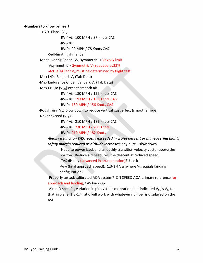
RV-Type Training Guide 87
-Numbers to know by heart
- > 20o Flaps: VFE
-RV-4/6: 100 MPH / 87 Knots CAS
-RV-7/8:
-RV-9: 90 MPH / 78 Knots CAS
-Self-limiting if manual!
-Maneuvering Speed (VA, symmetric) ≈ Vs x √G limit
-Asymmetric ≈ Symmetric VA reduced by33%
-Actual IAS for VA must be determined by flight test
-Max L/D: Ballpark VY (Tab Data)
-Max Endurance Glide: Ballpark VX (Tab Data)
-Max Cruise (VNO) except smooth air:
-RV-4/6: 180 MPH / 156 Knots CAS
-RV-7/8: 193 MPH / 168 Knots CAS
-RV-9: 180 MPH / 156 Knots CAS
-Rough air? VA: Slow down to reduce vertical gust effect (smoother ride)
-Never exceed (VNE) :
-RV-4/6: 210 MPH / 182 Knots CAS
-RV-7/8: 230 MPH / 200 Knots
-RV-9: 210 MPH / 182 Knots
-Really a function TAS: easily exceeded in cruise descent or maneuvering flight;
safety margin reduced as altitude increases; any buzz—slow down.
-Need to power back and smoothly transition velocity vector above the
horizon. Reduce airspeed, resume descent at reduced speed.
-TAS display (advanced instrumentation)? Use it!
-VREF (final approach speed): 1.3-1.4 VS1 (where VS1 equals landing
configuration)
-Properly tested/calibrated AOA system? ON SPEED AOA primary reference for
approach and landing, CAS back-up
-Aircraft specific, variation in pitot/static calibration; but indicated VS1 is VS1 for
that airplane, 1.3-1.4 ratio will work with whatever number is displayed on the
ASI
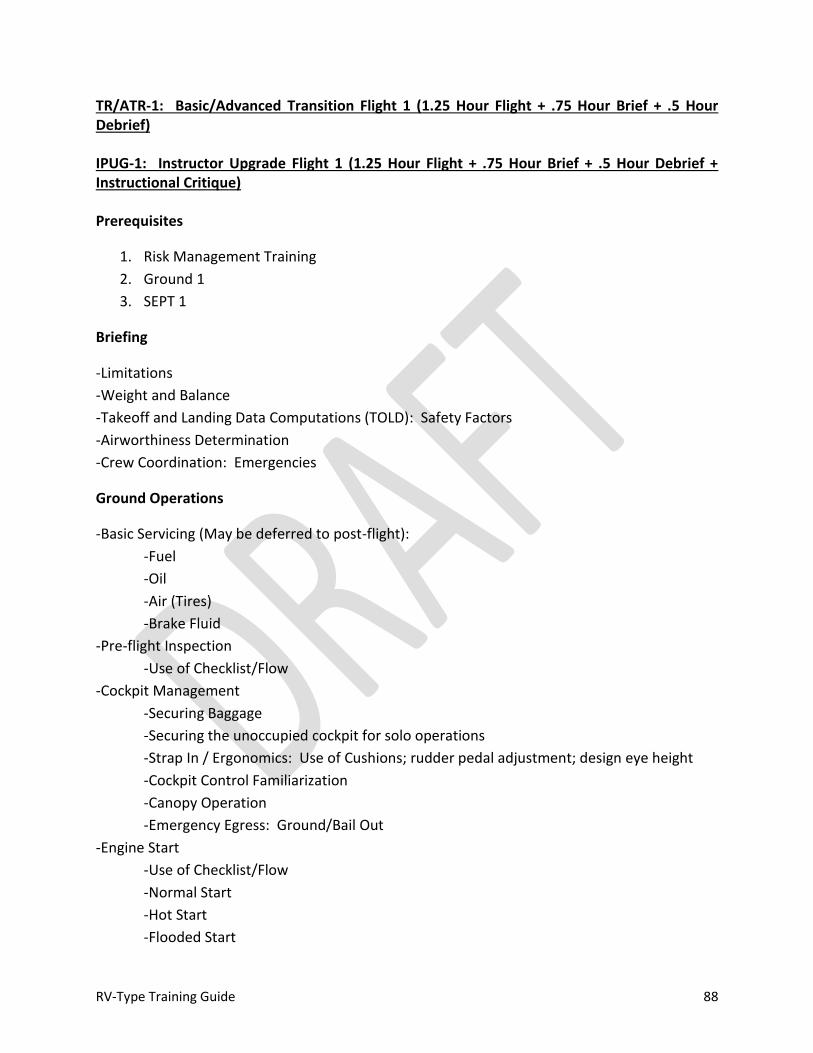
RV-Type Training Guide 88
TR/ATR-1: Basic/Advanced Transition Flight 1 (1.25 Hour Flight + .75 Hour Brief + .5 Hour Debrief)
IPUG-1: Instructor Upgrade Flight 1 (1.25 Hour Flight + .75 Hour Brief + .5 Hour Debrief + Instructional Critique)
Prerequisites
1. Risk Management Training
2. Ground 1
3. SEPT 1
Briefing
-Limitations
-Weight and Balance
-Takeoff and Landing Data Computations (TOLD): Safety Factors
-Airworthiness Determination
-Crew Coordination: Emergencies
Ground Operations
-Basic Servicing (May be deferred to post-flight):
-Fuel
-Oil
-Air (Tires)
-Brake Fluid
-Pre-flight Inspection
-Use of Checklist/Flow
-Cockpit Management
-Securing Baggage
-Securing the unoccupied cockpit for solo operations
-Strap In / Ergonomics: Use of Cushions; rudder pedal adjustment; design eye height
-Cockpit Control Familiarization
-Canopy Operation
-Emergency Egress: Ground/Bail Out
-Engine Start
-Use of Checklist/Flow
-Normal Start
-Hot Start
-Flooded Start

RV-Type Training Guide 89
-Leaning Mixture for Ground Operation
-Taxi
-Brake check
-Tail / Nose Wheel Steering
-Prop Blast and Power Control
-Proper position of Flight Controls
-S-Turns (when appropriate)
-Run-up
-Use of Checklist/Flow
-Positioning Aircraft: Hazards/Cooling
-Confirming Canopy Security
-Trim and Flap Setting
Takeoff and Departure
-Normal/Cross-Wind Takeoff
-Line-up Check
-Directional Control:
-Power Application/Torque/P-Factor
-Raising the Tail/Rotation
-Engine Power/Pressure Checks During Roll
-Rotation/Lift Off
-Climb
-Acceleration: Flap Retraction
-VY / Cruise Climb
-Power Adjustment / Temperature Monitoring
-Traffic Pattern Departure
-Level-Off
-Use of Trim
-Engine Management
Basic Aircraft Control
-Straight and Level Flight
-Visual References
-Pitch Stability Exercise
-Yaw Stability Exercise
-Roll Stability Exercise
-Acceleration/Deceleration
-Use of Rudder
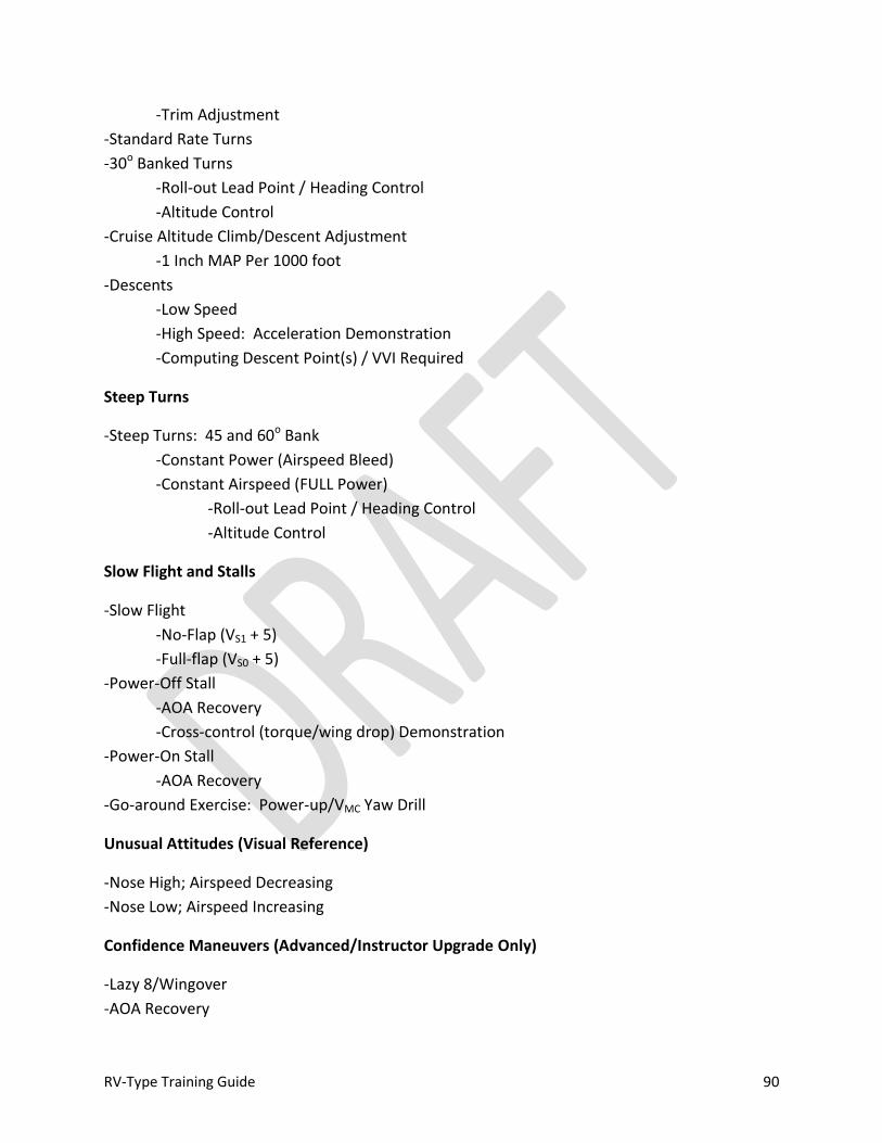
RV-Type Training Guide 90
-Trim Adjustment
-Standard Rate Turns
-30o Banked Turns
-Roll-out Lead Point / Heading Control
-Altitude Control
-Cruise Altitude Climb/Descent Adjustment
-1 Inch MAP Per 1000 foot
-Descents
-Low Speed
-High Speed: Acceleration Demonstration
-Computing Descent Point(s) / VVI Required
Steep Turns
-Steep Turns: 45 and 60o Bank
-Constant Power (Airspeed Bleed)
-Constant Airspeed (FULL Power)
-Roll-out Lead Point / Heading Control
-Altitude Control
Slow Flight and Stalls
-Slow Flight
-No-Flap (VS1 + 5)
-Full-flap (VS0 + 5)
-Power-Off Stall
-AOA Recovery
-Cross-control (torque/wing drop) Demonstration
-Power-On Stall
-AOA Recovery
-Go-around Exercise: Power-up/VMC Yaw Drill
Unusual Attitudes (Visual Reference)
-Nose High; Airspeed Decreasing
-Nose Low; Airspeed Increasing
Confidence Maneuvers (Advanced/Instructor Upgrade Only)
-Lazy 8/Wingover
-AOA Recovery

RV-Type Training Guide 91
-Deep Stall
Descent/RTB
-Computing Descent Point / Descent path control (Angle/VVI)
-Engine / Airspeed Management
Pattern and Landing
-Use of Checklist/Flow
-Pattern Entry
-Perch Management
-Base Turn
-Stabilized Final
-Slip
-Low-Approach and Go-Around
-Closed Pattern
-Runway Drag (Low Flight) Exercise
-Full-Stop Landings (TW: 3 point; wheel: tail-low)
-Normal
-Touchdown
-Roll-out Directional Control
-Brake Use
After Landing
-Use of Checklist/Flow
-Parking and Securing
-Post-flight Inspection
-Tie Down
-Control Locks and Covers
-Servicing
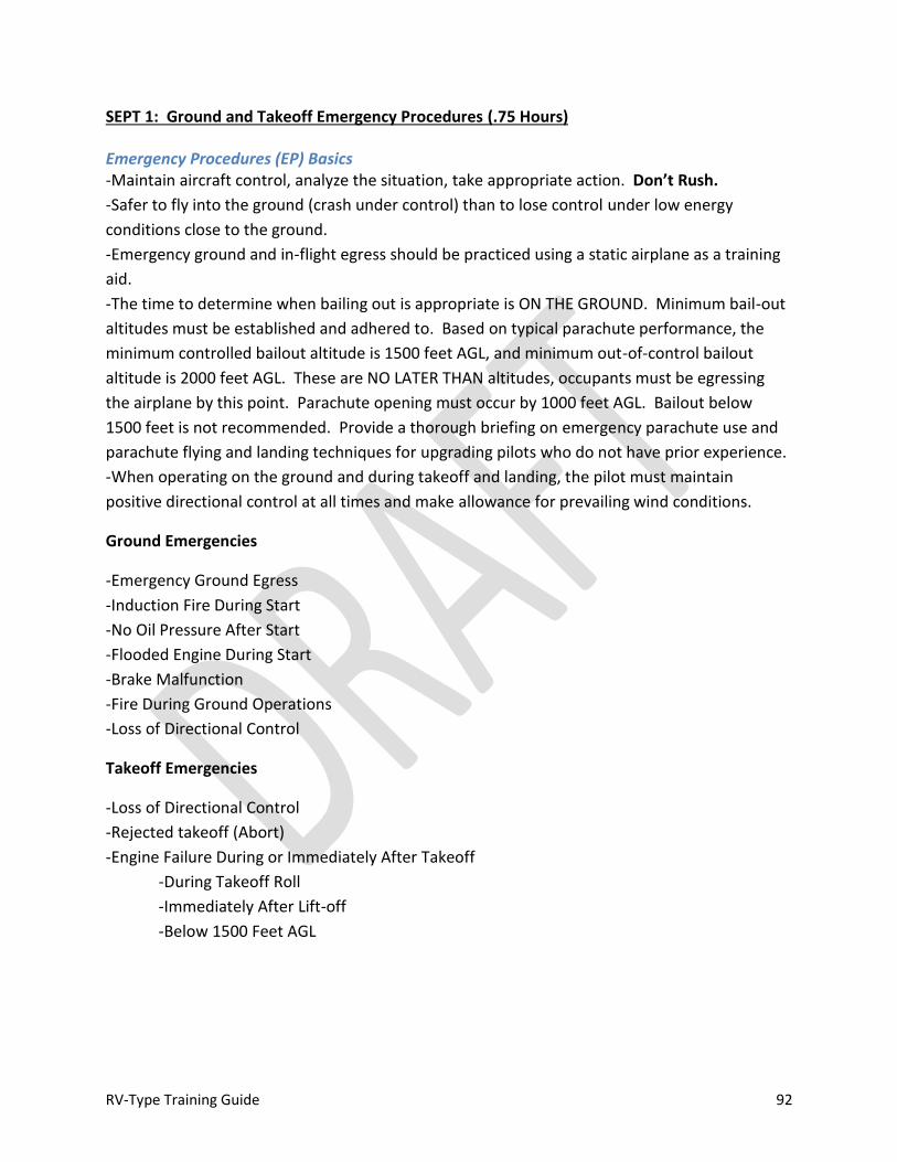
RV-Type Training Guide 92
SEPT 1: Ground and Takeoff Emergency Procedures (.75 Hours)
Emergency Procedures (EP) Basics -Maintain aircraft control, analyze the situation, take appropriate action. Don’t Rush.
-Safer to fly into the ground (crash under control) than to lose control under low energy
conditions close to the ground.
-Emergency ground and in-flight egress should be practiced using a static airplane as a training
aid.
-The time to determine when bailing out is appropriate is ON THE GROUND. Minimum bail-out
altitudes must be established and adhered to. Based on typical parachute performance, the
minimum controlled bailout altitude is 1500 feet AGL, and minimum out-of-control bailout
altitude is 2000 feet AGL. These are NO LATER THAN altitudes, occupants must be egressing
the airplane by this point. Parachute opening must occur by 1000 feet AGL. Bailout below
1500 feet is not recommended. Provide a thorough briefing on emergency parachute use and
parachute flying and landing techniques for upgrading pilots who do not have prior experience.
-When operating on the ground and during takeoff and landing, the pilot must maintain
positive directional control at all times and make allowance for prevailing wind conditions.
Ground Emergencies
-Emergency Ground Egress
-Induction Fire During Start
-No Oil Pressure After Start
-Flooded Engine During Start
-Brake Malfunction
-Fire During Ground Operations
-Loss of Directional Control
Takeoff Emergencies
-Loss of Directional Control
-Rejected takeoff (Abort)
-Engine Failure During or Immediately After Takeoff
-During Takeoff Roll
-Immediately After Lift-off
-Below 1500 Feet AGL
RV-Type Training Guide 93
Ground Lesson 2: RV-Type Performance (.75 Hours)
-NO TWO AIRPLANES ARE IDENTICAL / Performance Varies
-Engine / Prop / Weight / Empty CG
-“Light Nose” = O-320 + light-weight prop
-“Heavy Nose” = O-360 (or more) + constant speed prop
-Primary difference in take-off and landing performance
-Climb to lesser degree
-Cruise is cruise, regardless
-Apples to apples requires accurate calibrated airspeed data
-Van’s factory numbers accurate for properly “propped” airplanes at
similar gross weight
-Little or no difference on top end with cruise / constant speed prop
-Glide: Depends on propeller type/pitch fitted
-Large variation
-Light weight (e.g., wood) fixed pitch “cruise” prop tend to have
lowest rotating drag, i.e., best glide performance (ROT 10:1)
-Typical non-aerobatic controllable pitch propeller best
glide/lowest drag in LOW RPM (course pitch)
-Prop stopped: pays above 3000-4000 AGL--below that, limited benefit
-Problematic for controllable pitch propellers
-Never sacrifice control to stop prop
-Different airplane with passenger / cargo / density altitude ∆
-Quality of flight test and data varies
-Good takeoff and landing data is difficult to measure without proper equipment and
test procedures
-Accurate cruise data requires proper pitot/static testing
-Outstanding general performance CAN FOSTER COMPLACENCY
-Example: Van’s Numbers (160 HP RV-4)
-Prototype / standard conditions / fixed-pitch, wood prop / measured
-Solo weight data: 1160
-Real world example 985 lb empty weight + 170 lb pilot: 1335 lbs takeoff
weight with full fuel (115% of prototype #’s)
Block 2: Basic Transition/Advanced Transition/Instructor Upgrade
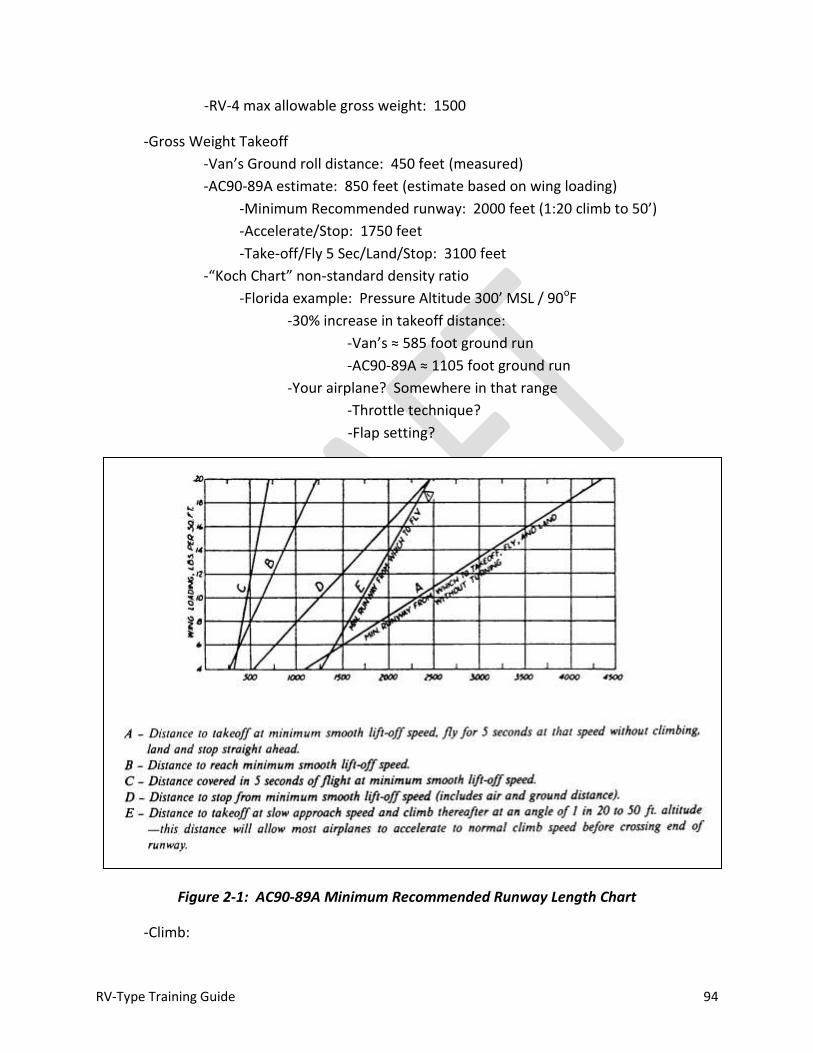
RV-Type Training Guide 94
-RV-4 max allowable gross weight: 1500
-Gross Weight Takeoff
-Van’s Ground roll distance: 450 feet (measured)
-AC90-89A estimate: 850 feet (estimate based on wing loading)
-Minimum Recommended runway: 2000 feet (1:20 climb to 50’)
-Accelerate/Stop: 1750 feet
-Take-off/Fly 5 Sec/Land/Stop: 3100 feet
-“Koch Chart” non-standard density ratio
-Florida example: Pressure Altitude 300’ MSL / 90oF
-30% increase in takeoff distance:
-Van’s ≈ 585 foot ground run
-AC90-89A ≈ 1105 foot ground run
-Your airplane? Somewhere in that range
-Throttle technique?
-Flap setting?
Figure 2-1: AC90-89A Minimum Recommended Runway Length Chart
-Climb:

RV-Type Training Guide 95
-VX largely a function of weight: decreases with weight (ball park 80-85 MPH /
70-75 Knots)
-VY largely a function of altitude: decreases with altitude (ball park 100-120
MPH / 90-105 Knots)
-“Flat” RV climb curve data = fairly consistent performance across a large
speed band…LIMFAC on bottom end? Engine cooling (CHT, if equipped)
-“Light nose” Cruise Prop (fixed pitch) ROT at 105-120 MPH / 90-105 Knots CAS
(nominal VY):
-Solo / Standard Winter: 1800-2000 FPM
-Solo / Summer: 1200-1500 FPM
-Gross / Standard: 1500-1700 FPM
-Gross / Summer: 1000-1200 FPM
-Bottom line: Airspeed as required to keep hottest cylinder at 380oF or
less and oil temperature within limits
-Constant speed prop: positive effect on takeoff and climb performance
-Cruise
-Is what it is! Only way to know for sure is to collect data
-Key: being able to establish a known power setting
-Tach/MAP required
-Review charts
-Manufacturer’s Charts/Power Curves (Engine Handbook?)
-Airplane charts (if available)
-No appreciable performance advantage for a constant speed prop over a
properly pitched fixed propeller in cruise flight
-Pick a power setting (55-65% sweet spot)
-Stock O-320 ROT: 7-8 GPH (properly leaned) at altitude (6-10K MSL)
-Stock O-360 ROT: 8-10 GPH (properly leaned) at altitude (6-10K MSL)
-Lycoming recommendation: 65% or less for max engine life
-LOP if you can get there
-Fuel flow vs. actual ground speed is all that matters
-No wind planning numbers?
-RV-4 Example: 150KCAS / 172MPH
-3+30 with 30 minute reserve (450 NM range)
-TAS ROT: add 4 (or 2%) knots / 1000’ to CAS
-Power Setting ROT: MP + RPM/100 ≈ % Power
“45” ≈ 65% (±3 for each 10% up or down)
-Example: 22.5” MP + 22(50) RPM ≈ 45 (65% power)
-Can also pull MP/RPM combination off of Lycoming graphic data
RV-Type Training Guide 96
-Cruise Climb/Descent: Airplane is extremely efficient…make 1” MAP per
1000’ power adjustments for 300-500 FPM ROC or descent for changing cruise
altitude
-Descent
-Descents take planning; Observe VNO (CAS) and VNE (TAS)
-Be alert for induction icing at reduced power settings
-Adjust pitch, set airspeed (trim) THEN adjust MP
-Smooth air ground speed: 3 NM/Min (180 Knots)
-3o = 3 NM per 1K’ to lose; “DME X 3”
-“Normal” 15-17” MAP/1800-2000 RPM
-Rough air ground speed: 2 — 2.5 NM/Min (120-150 Knots)
-Turn radius (NM) ≈ 1% ground speed
-ROT: 1NM to decel from cruise descent to holding speed; 2NM to decel
to approach speed
-Holding
-L/DMAX for max endurance (≈1.4 VS)
-Else, 120 MPH / 105 Knots CAS (≈ Carson’s speed)
-Power: 40-45% 16-17” MAP 1900-2000 RPM
-Pitch: +2.5o
-Fuel Flow: Lycoming ≈ .1 Gal/minute (e.g., 25 min hold ≈
2.5 Gal burned)
-Instrument Approach: GS x 5 = VVI for 3o approach path (400-500 FPM)
-3o VDP @ HAT/300 in miles from TDZ
-3o VDP by timing: 10% HAT subtracted from FAF to MAP timing
-90 MPH / Knots CAS, Flaps UP works well for approach speed,
low to ON SPEED/VREF when transitioning visually; maintain glide
path depicted on approach plate for final approach/transition to
landing (e.g., 3o)
-Dive/drive (non-precision): 10” MAP; 800-1000 FPM at MDA NLT
computed/published VDP
-CDA (constant descent approach) in lieu of dive/drive?
-Visual Stabilized Final: 300’ AGL 3K’ from TDZ; 6o (or ON SPEED/VREF
glide angle)
-Sufficient energy to reach TDZ power off
-Shallower descent angles (e.g., standard 3o) require power
-Landing

RV-Type Training Guide 97
-Normal landing distance ≈ 95% of takeoff distance
-Short field landing = back side of the power curve
-EXPECT float if flying standard 75-80 CAS (1.4 VS) power-off approach to
three-point
-Flaps UP to transition weight to the gear
-Constant speed prop? Whole different animal
-Bottom Line: 2000 foot minimum runway until you’re proficient
-Proficient? Operating off a short runway still carries increased risk
factor…

RV-Type Training Guide 98
TR/ATR-2: Basic/Advanced Transition Flight 2 (1.25 Hour Flight + .75 Hour Brief + .5 Hour Debrief)
IPUG-2: Instructor Upgrade Flight 2 (1.25 Hour Flight + .75 Hour Brief + .5 Hour Debrief + Instructional Critique)
Prerequisites
1. Block 1
2. Ground 2
3. SEPT 2
Briefing
-Limitations
-Weight and Balance
-Takeoff and Landing Data Computations (TOLD): Safety Factors
-Airworthiness Determination
-Crew Coordination: Emergencies
Ground Operations
-Review Basic Servicing (May be deferred to post-flight):
-Fuel
-Oil
-Air (Tires)
-Brake Fluid
-Pre-flight Inspection
-Flow
-Cockpit Management
-Canopy Operation
-Emergency Egress: Ground/Bail Out
-Engine Start
-Use of Checklist/Flow
-Normal Start
-Hot Start
-Flooded Start
-Leaning Mixture for Ground Operation
-Taxi
-Brake check
-Tail / Nose Wheel Steering
RV-Type Training Guide 99
-Prop Blast and Power Control
-Proper position of Flight Controls
-S-Turns
-Run-up
-Use of Checklist/Flow
-Positioning Aircraft: Hazards/Cooling
-Confirming Canopy Security
-Trim and Flap Setting
Takeoff and Departure
-Maximum Performance Takeoff (VX)
-Line-up Check
-Directional Control:
-Power Application/Torque/P-Factor
-Raising the Tail/Rotation
-Engine Power/Pressure Checks During Roll
-Rotation/Lift Off
-Climb
-Acceleration: Flap Retraction
-VX / High Power Climb
-Pitch Stability Exercise
-Engine Monitoring and mixture control
-Traffic Pattern Departure
-Level-Off
-Use of Trim
-Engine Management
Basic Aircraft Control
-Straight and Level Flight
-Visual References
-Pitch Stability Exercise
-Yaw Stability Exercise
-Roll Stability Exercise
-Acceleration/Deceleration
-Use of Rudder
-Trim Adjustment
-30o Banked Turns
-Roll-out Lead Point / Heading Control

RV-Type Training Guide 100
-Altitude Control
-Climbs and Descents
Steep Turns
-Steep Turns: 45 and 60o Bank
-Constant Power (Airspeed Bleed)
-Constant Airspeed (FULL Power)
-Roll-out Lead Point / Heading Control
-Altitude Control
Slow Flight and Stalls
-Slow Flight
-No-Flap (VS1 + 5)
-Full-flap (VS0 + 5)
-Power-Off Stall
-Unusual attitude + AOA Recovery
-Power-On Stall
-Unusual attitude + AOA Recovery
-Go-around Exercise: Power-up/VMC Yaw Drill
Unusual Attitudes (Visual Reference)
-Nose High; Airspeed Decreasing
-Nose Low; Airspeed Increasing
Confidence Maneuvers (Advanced/Instructor Upgrade Only)
-Lazy- 8/Wingover
-AOA Recovery
-Incipient Spin
Advanced Handling (Advanced/Instructor Upgrade Only)
-G Warm-up
-Basic Roll
-Loop
-Cloverleaf
Descent/RTB
-Use of Checklist/Flow

RV-Type Training Guide 101
-Computing Descent Point / Descent path control (Angle/VVI)
-Engine / Airspeed Management
Emergency Pattern
-High Key
-Low Key
-Base Turn
-Final
-TDZ Management
Pattern and Landing
-Use of Checklist/Flow
-Pattern Entry
-Perch Management
-Base Turn
-Stabilized Final
-Slip
-Low-Approach and Go-Around
-Closed Pattern
-Runway Drag Exercise
-Full-Stop Landings (TW: 3 point; wheel; tail-low)
-Normal
-Touchdown
-Roll-out Directional Control
-Brake Use
After Landing
-Use of Checklist/Flow
-Parking and Securing
-Post-flight Inspection
-Tie Down
-Control Locks and Covers
-Servicing
RV-Type Training Guide 102
SEPT 2: In-Flight Emergency Procedures (.75 Hours)
In-flight Emergencies
-Electrical Malfunction
-Low Amperage
-High Amperage
-Electrical Fire
-VMC Fire Extinguished
-IMC / Night Fire Extinguished
-Oil System Malfunction
-Engine Malfunction
-Engine Failure / Loss of Power
-Engine Fire
-Pitot / Static Malfunction
-Induction Icing
-Controllability Check
-Canopy Loss During Flight
-Cockpit Ventilation / Heat Malfunction
-Fuel Leak
-Fuel Transfer Malfunction
-EFIS Malfunction
-Flight Control Malfunction
-Trim Malfunction
-Flap Malfunction
-Glide Performance
-Altitude Lost in Gliding Turn
-Glide Chart
-Out-of-Control
-Spins
-Bail-out
-Passenger Incapacitation
-Emergency Descent
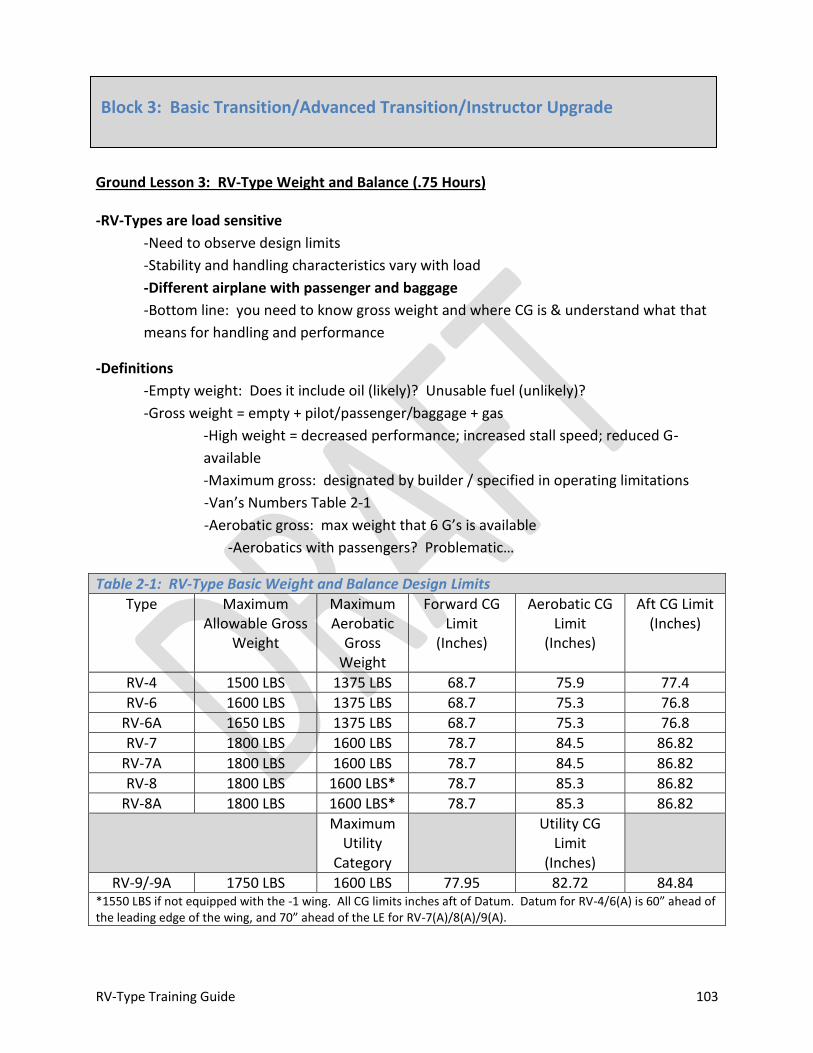
RV-Type Training Guide 103
Ground Lesson 3: RV-Type Weight and Balance (.75 Hours)
-RV-Types are load sensitive
-Need to observe design limits
-Stability and handling characteristics vary with load
-Different airplane with passenger and baggage
-Bottom line: you need to know gross weight and where CG is & understand what that
means for handling and performance
-Definitions
-Empty weight: Does it include oil (likely)? Unusable fuel (unlikely)?
-Gross weight = empty + pilot/passenger/baggage + gas
-High weight = decreased performance; increased stall speed; reduced G-
available
-Maximum gross: designated by builder / specified in operating limitations
-Van’s Numbers Table 2-1
-Aerobatic gross: max weight that 6 G’s is available
-Aerobatics with passengers? Problematic…
Table 2-1: RV-Type Basic Weight and Balance Design Limits
Type Maximum Allowable Gross
Weight
Maximum Aerobatic
Gross Weight
Forward CG Limit
(Inches)
Aerobatic CG Limit
(Inches)
Aft CG Limit (Inches)
RV-4 1500 LBS 1375 LBS 68.7 75.9 77.4
RV-6 1600 LBS 1375 LBS 68.7 75.3 76.8
RV-6A 1650 LBS 1375 LBS 68.7 75.3 76.8
RV-7 1800 LBS 1600 LBS 78.7 84.5 86.82
RV-7A 1800 LBS 1600 LBS 78.7 84.5 86.82
RV-8 1800 LBS 1600 LBS* 78.7 85.3 86.82
RV-8A 1800 LBS 1600 LBS* 78.7 85.3 86.82
Maximum Utility
Category
Utility CG Limit
(Inches)
RV-9/-9A 1750 LBS 1600 LBS 77.95 82.72 84.84 *1550 LBS if not equipped with the -1 wing. All CG limits inches aft of Datum. Datum for RV-4/6(A) is 60” ahead of the leading edge of the wing, and 70” ahead of the LE for RV-7(A)/8(A)/9(A).
Block 3: Basic Transition/Advanced Transition/Instructor Upgrade
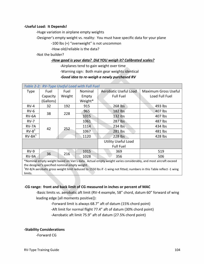
RV-Type Training Guide 104
-Useful Load: It Depends!
-Huge variation in airplane empty weights
-Designer’s empty weight vs. reality: You must have specific data for your plane
-100 lbs (+) “overweight” is not uncommon
-How old/reliable is the data?
-Not the builder?
-How good is your data? Did YOU weigh it? Calibrated scales?
-Airplanes tend to gain weight over time
-Warning sign: Both main gear weights identical
-Good idea to re-weigh a newly purchased RV
Table 2-2: RV-Type Useful Load with Full Fuel
Type Fuel Capacity (Gallons)
Fuel Weight
Nominal Empty
Weight*
Aerobatic Useful Load Full Fuel
Maximum Gross Useful Load Full Fuel
RV-4 32 192 915 268 lbs 493 lbs
RV-6 38 228
965 182 lbs 407 lbs
RV-6A 1015 132 lbs 407 lbs
RV-7
42 252
1061 287 lbs 487 lbs
RV-7A 1114 234 lbs 434 lbs
RV-81 1067 281 lbs 481 lbs
RV-8A1 1120 228 lbs 428 lbs
Utility Useful Load Full Fuel
RV-9 36 216
1015 369 519
RV-9A 1028 356 506 *Nominal empty weight based on Van’s data. Actual empty weight varies considerably, and most aircraft exceed the designer’s specified nominal empty weight. 1RV-8/A aerobatic gross weight limit reduced to 1550 lbs if -1 wing not fitted; numbers in this Table reflect -1 wing
limits.
-CG range: front and back limit of CG measured in inches or percent of MAC
-Basic limits vs. aerobatic aft limit (RV-4 example, 58” chord, datum 60” forward of wing
leading edge [all moments positive]):
-Forward limit is always 68.7” aft of datum (15% chord point)
-Aft limit for normal flight 77.4” aft of datum (30% chord point)
-Aerobatic aft limit 75.9” aft of datum (27.5% chord point)
-Stability Considerations
-Forward CG

RV-Type Training Guide 105
-Heavy stick
-lbs/G
-More aft stick for landing
-Improved stall/spin resistance & recovery
-Higher stall speed
-Higher trim drag (reduced top speed)
-Increased pitch stability
-Overall: more stable and safe; less fun to fly
-Aft CG
-Lighter stick
-Less stick required for landing (more pronounced pitch force changes in
ground effect)
-PIO?
-Less pitch stability
-Lower trim drag
-Decreased departure susceptibility
-Stall/Spin recovery slower; requires more positive control input
-Aerobatic limit is there for a reason: assume no margin
-Preserves reasonable stall/spin recovery characteristics / increased likelihood of
unintentional stalls (handling error)
-No intentional spins with CG aft of aerobatic limit
-Overall: less stable; more fun to fly
-Van: CG’s in aft half of range optimize handling harmony
-Sweet spot: RV-4 example 72.3 to 75.9”
-Exceeding aft limit is dangerous
-Control reversal possible
-CG Shift During Flight
-CG moves aft as fuel is burned
-“Most aft” at landing weight / BINGO / flame-out
-Anticipate pitch trim adjustment(s)
-May be possible to be in limits for takeoff and out of limits for landing
-Heavy passenger + baggage = worst-case
-Math
-Weight X Arm = Moment
-“Arm” is distance from “datum”
-Example: RV-4 datum 60” ahead of wing leading edge
-“Ground truth” data belongs in airframe log
RV-Type Training Guide 106
-Need sufficient data aboard to compute condition
-Must be dated
-Current data must be carried in cockpit
-Did you build or buy?
-New-to-you RV-type should be re-weighed
-Leveling datum? Van’s Builder’s Manual (e.g., canopy rail)
-Arms
-Pilot
-Pax (tandem)
-Fuel: CG moves aft as fuel is burned
-Baggage area(s)
-Daily computations:
-Most forward / most aft (worst-case comparison)
-Tabular data for your airplane?
-Garmin X96 weight and balance page?
-Program with data for your airplane
-Easy way to calculate CG every time you fly
-Compartment structural design limits
-Cockpits: RV-4 example, 240 lbs each
-Baggage compartment: RV-4 example, 100 lbs
-You’re plane?
-Still need to compute actual weight/balance
-Don’t confuse compartment limits with actual weight and balance condition/limits

RV-Type Training Guide 107
Blindfold Cockpit Check (.25 Hours)
-Upon completion of TR/ATR-2 and prior to TR/ATR-3, the instructor will conduct a blindfold
cockpit check. The upgrading pilot will be required to locate all cockpit controls, switches and
critical circuit breakers by feel.

RV-Type Training Guide 108
TR/ATR-3: Basic/Advanced Transition Flight 3 (1.25 Hour Flight + .75 Hour Brief + .5 Hour Debrief)
IPUG-3: Instructor Upgrade Flight 3 (1.25 Hour Flight + .75 Hour Brief + .5 Hour Debrief + Instructional Critique)
Prerequisites
1. Block 2
2. Ground 3
3. SEPT-3
Briefing
-Limitations
-Weight and Balance
-Takeoff and Landing Data Computations (TOLD): Safety Factors
-Crew Coordination: Emergencies
Ground Operations
-Pre-flight Inspection
-Flow
-Cockpit Management
-Emergency Egress: Ground/Bail Out
-Engine Start
-Use of Checklist/Flow
-Leaning Mixture for Ground Operation
-Taxi
-Brake check
-Tail / Nose Wheel Steering
-Run-up
-Use of Checklist/Flow
-Positioning Aircraft: Hazards/Cooling
-Confirming Canopy Security
-Trim and Flap Setting
Takeoff and Departure
-Maximum Performance Takeoff (VX)
-Line-up Check
-Directional Control:

RV-Type Training Guide 109
-Power Application/Torque/P-Factor
-Raising the Tail/Rotation
-Engine Power/Pressure Checks During Roll
-Rotation/Lift Off
-Climb
-Acceleration: Flap Retraction
-VX / High Power Climb
-Engine Monitoring
-Traffic Pattern Departure
-Level-Off
-Use of Trim
-Engine Management
Steep Turns
-Steep Turns: 45 and 60o Bank
-Constant Power (Airspeed Bleed)
-Constant Airspeed (FULL Power)
-Roll-out Lead Point / Heading Control
-Altitude Control
Slow Flight and Stalls
-Slow Flight
-No-Flap (VS1 + 5)
-Full-flap (VS0 + 5)
-Power-Off Stall
-Unusual attitude + AOA Recovery
-Power-On Stall
-Unusual attitude + AOA Recovery
Unusual Attitudes (Visual Reference)
-Nose High; Airspeed Decreasing
-Nose Low; Airspeed Increasing
Confidence Maneuvers (Advanced/Instructor Upgrade Only)
-Lazy- 8
-Incipient Spin
-Low AOA Aileron Roll

RV-Type Training Guide 110
Advanced Handling (Advanced/Instructor Upgrade Only)
-G Warm-up
-Loop
-Barrel Roll
-Immelman
Descent/RTB
-Use of Checklist/Flow
-Computing Descent Point / Descent path control (Angle/VVI)
-Engine / Airspeed Management
Emergency Pattern
-High Key
-Low Key
-Base Turn
-Final
-Energy/TDZ Management
Pattern and Landing
-Use of Checklist/Flow
-Pattern Entry
-Perch Management
-Base Turn
-Stabilized Final
-Slip
-Low-Approach and Go-Around
-Closed Pattern
-Full-Stop Landings (TW: 3 point; wheel; tail-low)
-Normal/Short/soft field
-Touchdown
-Roll-out Directional Control
-Brake Use
After Landing
-Use of Checklist
-Parking and Securing
-Post-flight Inspection
RV-Type Training Guide 111
SEPT 3: Landing Emergency Procedures (.75 Hours)
Landing Emergencies
-Landing With Known Flat tire
-Emergency Landing Pattern
-High Key
-Low Key
-Base Turn
-Touchdown
-Airspeed Indicator Failure
-Ditching

RV-Type Training Guide 112
Ground Lesson 4: EAB Airworthiness Determination (.75 Hours)
-Big Picture: Pilot determines airworthiness / Owner responsible for maintenance
-Pilot “airworthiness”
-Certificate on person
-ORIGINAL, valid medical on person
-Can’t be a copy (ramp check)
-Currency
-Logs: Not required to be carried in the aircraft
-Check ride / Competency check / Flight review
-Check-ride in lieu of
-Tail wheel endorsement
-Required day / night recency of experience
-Tail wheel takeoffs and landings must be to a full-stop
-May be required to submit documentation ex post facto if ramp checked
-Paperwork
A Special Airworthiness Certificate (Pink)
-Available and DISPLAYED IN COCKPIT
-N-number must match data plate / markings
-Only valid when OPERATING LIMITATIONS are aboard
R Registration Certificate
-Temporary? Pink, 120 day limitation
-Expiration date?
R Radio Station License
-Only required for flight outside of CONUS
-Canada/Bahamas/Mexico/Etc.
-FCC Form 605 / Schedule C to Apply
-If station license required, then restricted radio telephone operator’s
permit is required
O Operating Limitations
-Part of airworthiness certificate for experimental aircraft
-Letter issued by FSDO to original builder
W Weight and Balance Data
-Must be DATED and CURRENT
Block 4: Basic Transition/Advanced Transition/Instructor Upgrade
RV-Type Training Guide 113
-Can be a photo copy of airframe log
-Compass correction card?
-Most recent VOR check?
-Altimeter / pitot static check (24 months)?
-Transponder check (24 months)?
-ELT batteries (ramp check item)
-“D” cells in ELT: Batteries must have expiration date stamped
-Additional battery in instrument panel remote actuator switch
-Decel (G) switch check
-Recorded in log books / sticker?
-Placards:
-Experimental
-Passenger Warning
-”Condition” check vs. “Annual”
-Experimental (homebuilt) aircraft require a condition check
-Not “annual”
-Can be performed by any A&P or original builder if issued repairman’s
certificate
-AI is NOT required / there is no type certificate to comply with
-Due at the end of the 12th month
-Builder can develop checklist
-Do you have one?
-FAR 43 (Maintenance) DOES NOT APPLY TO EXPERIMENTAL AIRCRAFT, sort of…
-FAR 91.319(e) Operating Limitations
-FAR 43, Appendix D: General guidance for condition inspection
-All maintenance “IAW AC 43-13”
-43-13 forms baseline for accepted maintenance practice, use it!
-ANYONE can turn a wrench on an experimental aircraft
-Normal logging required
-Only an A&P, AI or original builder (with repairman’s certificate) can sign condition
inspection
-Certification and Modification
-FAR 21.191 governs certification of experimental aircraft
-FAA guidance in order 8130.2F
-“Phase I” is initial testing in restricted area
-“Phase II” is “normal ops” for experimental aircraft
RV-Type Training Guide 114
-Modification
-Major Change?
-May require FSDO interpretation
-Minor change definition: “…one that has no appreciable effect on
the weight, balance, structural strength, reliability, operation
characteristics, or other characteristics affecting the airworthiness…”
-Major change example: propeller swap
-”5 hours in the box” with FSDO letter required
-Some FAA maintenance inspectors are NOT familiar with homebuilt / experimental
certification
-Do your homework so you can issue the answer!
RV-Type Training Guide 115
TR/ATR-4: Basic/Advanced Transition Flight 4 (1.25 Hour Flight + .75 Hour Brief + .5 Hour Debrief)
IPUG-4: Instructor Upgrade Flight 4 (1.25 Hour Flight + .75 Hour Brief + .5 Hour Debrief + Instructional Critique)
Prerequisites
1. All SEPT Training Complete
2. Block 3
3. Ground 4
Briefing
-Limitations
-Weight and Balance
-Takeoff and Landing Data Computations (TOLD): Safety Factors
-Crew Coordination: Emergencies
Ground Operations
-Pre-flight Inspection
-Flow
-Cockpit Management
-Emergency Egress: Ground/Bail Out
-Engine Start
-Use of Checklist/Flow
-Leaning Mixture for Ground Operation
-Taxi
-Brake check
-Tail / Nose Wheel Steering
-Run-up
-Use of Checklist/Flow
-Positioning Aircraft: Hazards/Cooling
-Confirming Canopy Security
-Trim and Flap Setting
Takeoff and Departure
-High Density Altitude, Heavy Weight Takeoff
-Line-up Check
-Directional Control:
RV-Type Training Guide 116
-Power Application/Torque/P-Factor
-Raising the Tail/Rotation
-Engine Power/Pressure Checks During Roll
-Rotation/Lift Off
-Climb
-Acceleration: Flap Retraction
-VY Best Rate Climb
-Engine Monitoring
-Traffic Pattern Departure
-Level-Off
-Use of Trim
-Engine Management
Steep Turns
-Steep Turns: 45 and 60o Bank
-Constant Power (Airspeed Bleed)
-Constant Airspeed (FULL Power)
-Roll-out Lead Point / Heading Control
-Altitude Control
Slow Flight and Stalls
-Slow Flight
-No-Flap (VS1 + 5)
-Full-flap (VS0 + 5)
-Torque Induced Yaw (Go-around) Exercise
-Power-Off Stall
-Unusual attitude + AOA Recovery
-Power-On Stall
-Unusual attitude + AOA Recovery
Unusual Attitudes (Visual Reference)
-Nose High; Airspeed Decreasing
-Nose Low; Airspeed Increasing
Confidence Maneuvers (Advanced/Instructor Upgrade Only)
-Lazy- 8/Wingover
-Inverted Recovery

RV-Type Training Guide 117
-Cross-controlled Stalls: Skid/Slip
Advanced Handling (Advanced/Instructor Upgrade Only)
-G Warm-up
-Split-S
-Hammerhead
-Cuban 8
Descent/RTB
-Use of Checklist/Flow
-Computing Descent Point / Descent path control (Angle/VVI)
-Engine / Airspeed Management
Emergency Pattern
-High Key
-Low Key
-Base Turn
-Final
-Energy/TDZ Management
Pattern and Landing
-Use of Checklist/Flow
-Pattern Entry
-Perch Management
-Base Turn
-Stabilized Final
-Slip
-Low-Approach and Go-Around
-Closed Pattern
-Full-Stop Landings (TW: 3 point; wheel; tail-low)
-Normal/Short/soft field
-Touchdown
-Roll-out Directional Control
-Brake Use
After Landing
-Use of Checklist/Flow

RV-Type Training Guide 118
-Parking and Securing
-Post-flight Inspection
RV-Type Training Guide 119
Risk Management Review: Human Error (0.5 Hours)
-Error Control
-Accountability: yourself, your family and your fellow aviators—you are responsible for
your actions; general aviation is “self-policing” –personal integrity is REQUIRED
-Non-compliance will kill you in aviation: What good are FAR’s, technical
manuals, procedures, and approved techniques, etc. if you don’t comply?
You’ve just broken the chain at the most basic level
-Self-discipline is critical
-Is “good enough” acceptable? Are you executing as well as you can (“top of
your game”)?
-If you’re aiming for “safe,” you’re aiming too low
-Required value: excellence in all you do
-Anchor yourself in the present: accept reality for what it is
-Hope is NOT a strategy
-Slow down and get there faster: accuracy trumps speed
-Rushing usually takes longer than slowing down in a high workload environment
-Negative feedback ISN’T: it’s required to improve
-Best source of negative feedback? You
-Park your ego; take no offense
-Pay Attention to Detail
-Aviation is inherently unforgiving of error, there’s nothing bigger than the little
things
-Error Producing Conditions
-Fatigue: #1 cause; we can be lousy spotting it in ourselves (increases probability of
error by a factor of 50)
-Acute: Short-term
-Chronic: Long-term; effects are CUMULATIVE; recovery varies with severity
-Personal symptoms?
-Easiest to fix, counter with rest: 8 hours of sleep desired, naps (20-30 minutes)
help
-High Risk/Low Frequency events (increase error probability by 17)
Block 1: Advanced Top-Off

RV-Type Training Guide 120
-Short field, obstructed approach
-High density altitude, maximum gross weight takeoff
-Counter by recognizing potential; prepare
-Time Pressure (increase error probability by a factor of 11)
-Classic “get thereitis”
-Counter by recognizing it; turn it off
-Objectively remove yourself from the timeline: reset as required
-EXTERNAL, e.g., the engine quits? You’ve still got X amount of altitude (energy)
and Y amount of time to work the problem…take it one step at a time and work
the problem
-Counter by prioritizing and using all time available: If you’ve got six seconds
available, spend 5 seconds thinking and 1 good second executing!
-Low Signal to Noise Ratio (increase error probability by a factor of 10)
-Excessive background noise; most prevalent during high or low workload phases
-High workload = lots of noise
-Low workload = complacency
-Counter by identifying high/low workload segments; “sterile cockpit”
-One Way Decision Gates (increase error probability by a factor of 8)
-“Point of no return;” late recognition won’t help
-Counter with exit strategy: if/then logic (e.g., missed approach criteria)
-Information Overload (increase error probability by a factor of 6)
-Confusion caused by too much data; adds stress
-Classic aviation example: channelized attention
-Counter by prioritizing: what’s important now?
-Poor Communication (increase error probability by factor of 6)
-Listening is (usually) more important than talking
-Counter by listening actively; strive for clear/concise; confirm (read-back)
-Faulty Risk Perception (increase error probability by a factor of 4)
-Failure to ID risk; ID the WRONG risk; comfort with risk
-Understand the real math: quantitative analysis? Don’t fret mid-air collision or
inflight fire to the extent you disregard stall/spin during approach and landing…
-Counter by listing risk factors and prioritizing; set realistic risk level—there is no
such thing as “low risk flying”
-Distraction
-Look for interruption in routine
-Counter by actively directing attention
-Routine Non-compliance
-“Normalization of Deviance”

RV-Type Training Guide 121
-Coined in the wake of Challenger investigation
-This is what occurs when there is NO NEGATIVE CONSEQUENCE
-Rule violation
-Bad judgment
-Ignorance
-Eventually, the math catches up with you
-Counter by applying integrity, self-discipline and excellence in all you do
-Making Mistakes
-Mistakes take you off your game: FIDO, “forget it and drive on”
-Address when appropriate (debrief, or even never), not “now”
-Hazardous Attitudes
-Anti-authority
-“No one tells me what to do”
-Impulsiveness
-“I need to do something about this NOW”
-Invulnerability
-“Can’t happen to me”
-Too competitive/macho
-“That’s nothing, watch this”
-Resignation
-“Why bother, there’s nothing we can do”
-Pressing Too Far
-“I’ve got somewhere I’ve GOT to be”
-Vanity/Ego
-“I’d rather die than look bad”
-Procrastination
-“I’ll get to it”
RV-Type Training Guide 122
Ground 1: RV-Type Handling (.75 Hours)
-NO TWO AIRPLANES ARE IDENTICAL / Handling Characteristics Vary
-Construction: Rigging/Fairings
-Configuration / Weight (CG)
-Different airplane with passenger and/or baggage aboard
-Performance and handling characteristics validated by flight test?
-Static Margin (Pitch Stability)
-More pronounced variation with tandem versions: Pitch stability trends towards
neutral as RCP and baggage load increases; side-by-side types, less CG range/effect
-All RV’s: CG moves aft (decreasing margin) as fuel is burned
-Tandem: Movement proportional to initial load—if RCP is occupied/baggage
carried, shift will be GREATER than if solo
-Review Weight and Balance information, and determine maximum loads to:
A) Operate within aerobatic envelope
-Observing design limits critical to ensure adequate handling
characteristics
B) Determine G allowable
-“G Available” is the amount of G the airplane is capable of generating at
any time as a result of dynamic pressure (speed). Above VA, G available
exceeds design limits.
-“G Allowable” is the amount of G the airplane can sustain and remain
within design limits. G allowable decreases as gross weight increases.
-“Asymmetric G Allowable” is the amount of G the airplane can sustain
when maneuvering about two axes simultaneously. It is always less than
“symmetric G allowable.”
C) Establish “target G”
-“Target G” is the amount of G applied to achieve a desired maneuver.
-Anticipate (neutral) control response
-Be ready to move the stick as required to establish desired attitude and AOA;
anticipate over-shoot tendency
-The key is to monitor pitch RATE when maneuvering and move the stick
appropriately (e.g., high climb angles)
Note
IAW Training Rules, the maximum target G is 4.

RV-Type Training Guide 123
-SMOOTH APPLICATION OF FLIGHT CONTROLS IS CRITICAL
-DO NOT EXCEED AFT CG LIMIT
-Airplane does not become suddenly uncontrollable, however designer’s limits
ARE NOT CONSERVATIVE—ASSUME NO MARGIN AT AFT AEROBATIC CG LIMIT
-Critical to ensure adequate (spin) recovery characteristics
-Aerobatics with passengers? Problematic for most airplanes due to
weight restrictions (as well as CG)
-Stick Force Lightening: Gradient linear for a given TAS / CG combination, but:
-Stick length or geometry may be adjusted by builder
-Stability / margin affected by ATTITUDE
-Nose-up, low airspeed, high power (VX climb) = reduced margin
-Acrobatics: longitudinal axis nearly vertical = reduced margin
-Landing: ground effect + low aspect ratio = pitch adjustment
during the flare (ease or stick forward, more pronounced in
tandem airplanes)
-Handling improves as speed decreases
-Heavy stick with forward CG / high speed
-Biggest impact on stick force gradient: CG location
-Larger variability in Tandem versions
-Maximum Allowable Gross Weight
-Operation Limitations/Builder specifications vs. designer’s limits
-Structural margin UNKNOWN when operating beyond design limits
Table 2-3: RV-Type Aerobatic Limits
Type Max Aero Gross
+ G Limit - G Limit Forward CG Limit1
Aerobatic CG Limit1
RV-4
1375 LBS
+ 6.0 - 3.0
68.7
75.9
RV-6 75.3
RV-6A
RV-7 1600 LBS
78.7
84.5 RV-7A
RV-8 1600 LBS* 85.3
RV-8A *1550 LBS if not equipped with the -1 wing. Asymmetric maneuvering reduces allowable G by 20-33%: -2.4 to +4.8 or -2.6 to +4.0. Asymmetric G limits are not specified by Van’s Aircraft. 1Inches aft of datum. Datum for RV-4/6(A) is 60” ahead of the leading edge of the wing, and 70” ahead of the LE
for RV-7(A)/8(A).
-Yaw
-Positive stability throughout the envelope
-Excursions (fish tailing) likely in turbulence

RV-Type Training Guide 124
-Rudder NOT effective for singular roll control (lift vector placement)
-Limited dihedral effect to generate roll
-Sufficient volume to be effective post-stall
-Slips: full deflection slips with or without flaps practical
-No appreciable effect on CAS (wing mounted pitot)
-Effect of gear fairings
-Destabilizing when installed (vertical area ahead of aerodynamic center)
-Roll
-Tending to neutral stability throughout the envelope
-Aileron primary means of controlling roll / lift vector
-Rudder somewhat effective at high AOA
-Overall Control Harmony: very light ailerons, light rudder, heavier elevator
-Stability Check
-Flown before maximum performance maneuvering
-Provides expectation that aircraft is rigged properly and basic stability is present on
each axis
-Risk mitigation considerations:
-Aircraft must be loaded within designer’s limits
-Actual weight and balance should be calculated (how accurate is the data?)
-How to execute:
-Establish trimmed level cruise flight
-Pitch: Ease nose up 10-20o and relax longitudinal pressure
-Observe deadbeat response (tendency to return to trim condition)
-Reestablish trimmed level cruise
-Roll: Apply 45o bank and relax lateral pressure
-Observe roll response (neutral or slight tendency to roll wings level)
-Reestablish trimmed level cruise
-Yaw: Note slip indicator then smoothly apply rudder and relax pedal pressure
-Observe yaw response (tendency for yaw excursions to damp)
-Reestablish trimmed level cruise
-Stalls: straight wing, Frise-type ailerons, no wash-in or wash-out, no stall strips (most
airplanes)
-Power-off: non-event (e.g., 60 MPH / 52 Knots CAS)
-Notable torque effect at all power settings (including idle)
-Use rudder to keep the ball centered
-May have to sacrifice desired attitude or heading control
RV-Type Training Guide 125
-If aileron is used to counter torque at idle, sufficient cross-control
will exist at stall to cause a (left) wing drop
-Nose may or may not drop if full aft stick is held
-Distinct buffet
-CG dependent (more pronounced in Tandem): with forward CG,
airplane “nods” and remains controllable post stall; with aft CG
airplane remains in stalled condition and may depart (spin) with little
warning (will recover quickly, ¼ to ½ turn with neutral controls [ease]
with neutral rudder)
-Wing drop common in deep stall; yaw in direction of wing drop
-Aircraft will tend to depart in yaw if deep stall is held
-First indication of breakdown in directional stability: nose slice
-Rudder effective to counter slice; heading control not practical
-More distinct drop with flaps; left roll tendency
-Less buffet than clean stall/Limited aerodynamic warning
-Accelerated: Any attitude/any airspeed
-AERODYNAMIC WARNING PROPORTIONAL TO G-LOAD
-Minimal buffet at low G
-Rapid application of flight controls? Can “beat” aerodynamic
warning (i.e., stall without observed warning cues)
-2.1 G stall @ ≈ 80 MPH CAS (Pattern speed); 60o bank?
-3G @ ≈ 95
-4G @ ≈ 110
-5G @ ≈ 123
-6G @ ≈ 135 (nominal VA)
-Power on? Same except (much) higher pitch attitude with lift vector perpendicular
to the horizon; more pronounced torque effects
-AOA or Stall Warning System?
-Design speed range
-VS to VNE ≈ 4:1 ratio
-What all this aerodynamic efficiency really means: ANY TIME THE VELOCITY
VECTOR IS BELOW THE HORIZON SMOOTH AIRSPEED/G CONTROL IS CRITICAL
-ROT: Nose down = throttle back (more critical with fixed-pitch propeller)
-Need to check airspeed before pull-through when inverted
-“Bail out” (recover to wing’s level) if too fast (e.g., ≥ 110 MPH /
95 Knots)
-Consider lower speed limit for pull-through until proficiency is
gained

RV-Type Training Guide 126
-G-onset rate is critical for keeping speed under control
-E.g., back side of a loop/split S; unusual attitude or dive recovery
-Also means you’ve generally got plenty of power available
-Takeoff/Go-around throttle control: torque/P-Factor and yaw…bottom
line: smooth, deliberate throttle control required
-Symmetric vs. Asymmetric Maneuvering
-Symmetric: one axis at a time
-Roll THEN pull
-Asymmetric: one or more axis simultaneously (e.g., barrel roll)
-Rolling AND pulling
-Puts more stress on the airframe
-Van’s Aircraft doesn’t specify asymmetric G limits
-ROT: reduce “g allowable” by 20-33%
-Maneuvering Speed/”Corner Velocity”
-Understanding and properly applying maneuvering speed is a critical concept
-“Maneuvering speed” = “corner velocity”
-NOT a static value: changes as a function of gross weight (decreases with weight)
-Calculate appropriate reference numbers for symmetric and asymmetric
application of flight controls (G) for actual flight configuration
-Have two “hang your hat” numbers available, one for symmetric, one for
asymmetric
-VA = VS (stall speed) x √ (square root) G-limit
-Symmetric positive g-limit = 6
-Square root of 6 ≈ 2.5
-Therefore, symmetric VA ≈ 2.5 x stall speed
-Asymmetric positive g-limit = 4
-Square root of 4 = 2
-Therefore, asymmetric VA ≈ 2 x stall speed
-VA is really the stall speed that corresponds to a particular limiting G
-ROT training envelope: 4G’s, speed at or below VNO, snap maneuvering
initiated below calculated asymmetric VA
-Designer’s viewpoint: RV-types not conducive to “snap” maneuvers
-Loaded within design limits and good stability check? Maneuver symmetrically with
impunity below corner; aircraft will stall before load limit is exceeded
-Above corner? G application is CRITICAL; i.e., how you move the stick
-Smooth, cruciform application of flight controls
-Load limits will be exceeded before the airplane stalls
RV-Type Training Guide 127
-At normal RV cruise speed it’s possible to develop 9.5 to in excess of 11 G’s with
abrupt stick application
-Example: Loop entry target speed 180 MPH CAS, target G 4; but use
caution—aerodynamically 10.7 G’s are available at the start of that
maneuver—only 6 G’s are allowable assuming loaded within aerobatic
design limits
-Best instantaneous turn performance in any plane occurs at corner velocity: minimum
radius; maximum rate
-Loss of Control
-Indications prior to loss of control:
-Buffet; and/or
-Nose stops tracking; and/or
-Wing drop/rock; and/or
-Nose Slice (yaw); and/or
-Nose Rise (stick force lightening)
-Power Effects
-Tends to lead to left yaw/slice
-Mitigated with idle power, but present at ALL power settings
-“Unload for Control” Concept: AOA recovery (stall)
-If in doubt, it is safer to establish a zero to ¼ G condition and wait for the nose
to drop and airspeed to increase; i.e., be patient the airplane WILL recover (if the
ground doesn’t get in the way—but you mitigate that risk if you have sufficient
altitude available, i.e., fly within the “training rules”
-“Idlize and Neutralize”
-Ailerons Neutral; Unload for Control (0 – 1/2 G); Rudder (as required) Opposite Yaw
-Establish 0 to ½ G condition regardless of attitude
-Engine (oil) limitations / fuel starvation (carb)
-Carb float is poor man’s aural G-meter!
-Does an inverted oil system work at zero G?
- Stall speed dramatically reduced (zero G = zero VS)
-Airplane is ballistic
-Unloaded; airspeed increasing
-Velocity vector on/below horizon
-Roll to recover
-ROT Nose high: Degrees nose up (start) = degrees nose low (finish)
-Nose low: airspeed build-up is primary concern
-Fuel odor in the cockpit? Normal (vents)
-Anticipate oil loss at/below ¼ G condition (engine stops if carbureted)
RV-Type Training Guide 128
-Power: As required
-Idle to reduce power effects
-Carbureted engine? Don’t be surprised if it quits
-Prop likely to stop if it’s light weight (wood)
-Be ready for air-start post recovery
-Starter vs. dive to windmill
-Prioritize: maintaining or regaining aircraft control is more important than
engine management
-Airplane is no longer “out-of-control” if it is unloaded and airspeed is increasing
through 100 MPH / 90 Knots
-Unintentional Spins
-Airplane resistant to spins unless pro-spin controls are input/held
-Spin resistance proportional to CG location…airplanes more spin prone,
less warning with AFT CG (Tandem)
-Neutralizing the controls will always help
-Incipient phase: recovery in ½ to ¾ turn likely if controls released
immediately
-Inertial coupling may occur if you apply anti-yaw rudder with simultaneous
forward stick (auto roll).
-Think of “stick forward” as “ease” or “release back pressure”
-Low Altitude
-Consider unintentional spins that occur in the traffic pattern to be non-
recoverable (i.e., fatal)
-AOA/Airspeed awareness is critical in the pattern
-Observe min airspeed / Max AOA limits
-A 2-G accelerated stall occurs at approximately 80 MPH CAS
-Skidding turns higher risk than slipping turns
-A departure from a skid will result in nearly immediate auto-
rotation in the direction of yaw
-Below 2500’ AGL, uncontrolled bailout is not practical.
-No man’s land: Anti-spin controls NLT 1500’ AGL with PERFECT dive recovery
technique—you MIGHT make it; but you are below minimum out-of-control bail-
out altitude
RECOVERY BOLDFACE (Boldface = memory item)
-POWER IDLE
-CONTROLS NEUTRAL
-“Idilize and Neutralize”
-Recovery within 1 to 1 ½ turns no other action
RV-Type Training Guide 129
-RUDDER OPPOSITE YAW (IF REQUIRED)
-Cruciform stick motion
-Tandem/forward CG: Inertial coupling possible
-Auto roll tendency if rudder deflected
-Nose tuck past vertical if spin is result of “normal”
attitude stall
-If rotation increases, use “other” opposite rudder
-ELEVATOR PAST NEUTRAL (IF REQUIRED)
-What does it take to break the stall?
-Upright = forward
-Inverted = aft
-Target zero G
-How to move the stick: smooth/aggressive
-Altimeter/bail-out cross-check? Must be OUT of the plane NLT 2500 AGL
for out-of-control
-Intentional Spin Characteristics
-Designer’s viewpoint: not a recreational maneuver
-Difference between tandem and side-by-side variants
-Aircraft to aircraft differences
-Pro spin controls must be maintained throughout incipient phase (≈ 2 turns)
-Expect nose tuck past vertical
-Some airplanes may enter a spiral dive vs. spin at forward CG locations
-If speed increasing above 100 Knots/MPH, recover immediately
-Power above idle may improve elevator effectiveness and help
force spin entry
-Nose low, high rotation rate: 180-270 deg/sec
-Full aft stick SLOWS rotation rate
-If stick is allowed to float, expect outside aileron to float up; drive stick off
center (opposite spin direction)
-Maintain pro-spin controls until it’s time to recover!
-Zero CAS, VVI pegged, 1 G, ball opposite spin (EFIS indications?)
-300-500 ft/turn, 2 sec/turn
-3000 AGL 6 turns and 12 seconds from impact
-1500 AGL 3 turns and 6 seconds from impact
-Recovery requires 1.5 turns and 1000’ of altitude
-Initiate recovery NLT Floor + 1000’
-More than 7 turns can disorient
RV-Type Training Guide 130
-Always recover before your inner ear tumbles; tolerance will
improve with exposure (and can decrease with illness!)
-Gee Whiz
-Power on spins = higher nose attitude / slower rotation rate
-10 turn spin + recovery requires ≈ 3500’ of altitude
-Dive Recovery
-RV types accelerate fast when the velocity vector is below the horizon
-More pronounced with fixed-pitch propellers
-As a general rule, throttle back when the nose is tracking down through or below the
horizon; be ready to apply G to keep speed under control
-Most common error in dive recovery is slow application of back stick during the
initial phase of the recovery
-Altitude lost in a dive is a function of radial G and TAS
-Numbers to know by heart
-Maneuvering Speed
-Symmetric = 2.5 x VS
-Asymmetric = 2 x VS
-Max L/D: Ballpark? VY
-Max Cruise except smooth air
-Never exceed: red line
-Really a function of TAS

RV-Type Training Guide 131
ATO-1: Advanced Top-Off Flight 1 (1.0 Hour Flight + .75 Hour Brief + .5 Hour Debrief)
Prerequisites
1. Risk Management Review complete
2. Ground 1
Briefing
-Limitations/Weight and Balance
-Emergency Egress: Bail-out
-Crew Coordination: Emergencies
-Unusual Attitude Recovery
-Advanced Handling: Confidence Maneuvers and Aerobatics
-Emergency Procedures: SFO Review
Ground Operations
-Pre-flight Inspection/Servicing
-Cockpit Management
-Emergency Egress: Ground/Bail Out
-Securing Lose Items
-Use of Checklist/Flow
-Engine Start
-Taxi
-Brake/steering check
-Run-up
-Positioning Aircraft: Hazards/Cooling
Takeoff and Departure
-Use of Checklist/Flow
-Normal/Cross-Wind Takeoff
-Line-up Check
-Directional Control:
-Power Application/Torque/P-Factor
-Raising the Tail/Rotation
-Engine Power/Pressure Checks During Roll
-Rotation/Lift Off
-Climb
-Acceleration: Flap Retraction
RV-Type Training Guide 132
-VY / Cruise Climb
-Power Adjustment / Temperature Monitoring / Proper Use of Mixture Control
-Pattern Departure
-Level-Off
-Use of Trim
-Engine Management
-Stability Check: Pitch / Roll / Yaw
Steep Turns
-Steep Turns: 60o Bank
-Constant Power (Airspeed Bleed)
-Constant Airspeed (FULL Power)
-Roll-out Lead Point / Heading Control
-Altitude Control
Slow Flight and Stalls
-Slow Flight Review
-No-Flap (VS1 + 5)
-Power-Off Stall Review
-Power-Off Deep Stall
-Power-On Stall Review
Unusual Attitudes (Visual Reference)
-Nose High; Airspeed Decreasing
-Nose Low; Airspeed Increasing
Confidence Maneuvers
-Lazy- 8/Wingover
-Incipient Spin
-AOA Recovery
-Low AOA Aileron Roll
Advanced Handling
-G Warm-up
-Acceleration Maneuver
-Aileron Roll
-Barrel Roll
RV-Type Training Guide 133
-Loop
-Cloverleaf
Descent/RTB
-Descent Planning
-Engine / Airspeed Management
Emergency Pattern
-High Key
-Low Key
-Base Turn
-Final
-Energy/TDZ Management
Pattern and Landing
-Use of Checklist/Flow
-Pattern Entry
-Perch Management
-Base Turn
-Stabilized Final
-Slip
-Low-Approach and Go-Around
-Closed Pattern
-Full-Stop Landings
After Landing
-Use of Checklist/Flow
-Parking and Securing

RV-Type Training Guide 134
Ground Lesson 2: RV-Type Handling (.75 Hours)
-NO TWO AIRPLANES ARE IDENTICAL / Performance Varies
-Engine / Prop / Weight / Empty CG
-“Light Nose” = O-320 + light-weight prop
-“Heavy Nose” = O-360 (or more) + constant speed prop
-Primary difference in take-off and landing performance
-Climb to lesser degree
-Cruise is cruise, regardless
-No difference on top end with cruise / constant speed prop
-Glide: Depends on propeller type/pitch (ROT: 10:1 or better)
-Different airplane with passenger / cargo / density altitude ∆
-RV-Types are load sensitive
-Need to observe design limits
-Stability and handling characteristics vary with load
-Different airplane with pax and baggage
-Bottom line: you need to know gross weight and where CG is & understand what that
means for handling and performance
-CG range review: front and back limit of CG measured in inches or percent of MAC
-Basic limits vs. aerobatic aft limit (RV-4 example, 58” chord, datum 60” forward of wing
leading edge [all moments positive]):
-Forward limit is always 68.7” aft of datum (15% chord point)
-Aft limit for normal flight 77.4” aft of datum (30% chord point)
-Aerobatic aft limit 75.9” aft of datum (27.5% chord point)
Math review
-Weight X Arm = Moment
-“Arm” is distance from “datum”
-Example: RV-4 datum 60” ahead of wing leading edge
-“Ground truth” data in airframe log
-Need sufficient data aboard to compute condition
-Must be dated
-Did you build or buy?
Block 2: Advanced Top-Off
RV-Type Training Guide 135
-New-to-you RV-type should be re-weighed
-Leveling datum? Van’s Builder’s Manual…
-Arm
-Pilot
-Pax (tandem)
-Fuel: CG moves aft as fuel is burned
-Baggage area(s)
-Daily computations:
-Most forward / most aft (worst-case comparison)
-Tabular data for your airplane?
-Garmin X96 weight and balance page? iPad App?
-Program with data for your airplane
-Easy way to calculate CG every time you fly
-Compartment structural design limits review
-Cockpits: RV-4 example, 240 lbs each
-Baggage compartment: RV-4 example, 100 lbs
-You’re plane?
-Still need to compute actual weight/balance
-Quality of flight test data and pilot handbook/documentation varies
-Outstanding general performance CAN FOSTER COMPLACENCY
-Stability Considerations
-Forward CG
-Heavy stick
-lbs/G
-More aft stick for landing
-Improved stall/spin resistance & recovery
-Higher stall speed
-Increased pitch stability
-Overall: more stable and safe; less fun to fly
-Aft CG
-Lighter stick
-Less stick for landing
-PIO?
-Less pitch stability
-Decreased departure susceptibility
-LOWER STATIC MARGIN
RV-Type Training Guide 136
-Stall/Spin recovery slower; requires more positive control input
-Aerobatic limit is there for a reason: assume no margin
-Preserves reasonable stall/spin recovery characteristics / increased likelihood of
unintentional stalls (handling error)
-No intentional spins with CG aft of aerobatic limit
-Overall: less stable; more fun to fly
-Van: CG’s in aft half of range optimize handling harmony
-Exceeding aft limit is dangerous
-Control reversal probable
-CG Shift During Flight
-CG moves aft as fuel is burned
-“Most aft” at landing weight / BINGO / flame-out
-May be possible to be in limits for takeoff and out of limits for landing
-Heavy passenger + baggage = worst-case
-“Aerobatic” Configuration
-Your airplane; your limits
-de facto: Single-seat aerobatic airplane; full design envelope available for maneuvering
flight
-You might still be there with a light passenger
-Wiggle room? G-allowable computation and CG Location
-Treat aerobatic aft CG limit as sacrosanct
-6 positive G’s allowable at maximum aerobatic gross weight
-G limit at design maximum gross weight? Interpolation?
-Asymmetric considerations: reduce limit by 20%
-Bottom line: some degree of maneuvering practical up to design maximum
gross weight…but you need to establish that envelope
-This envelope will be less forgiving of error that basic aerobatic envelope
-Parachutes are heavy; 2 adds approximately 30 lbs to bottom line…
-“Normal” aerobatic envelope (assuming no inverted systems installed): 0 to +4 G’s;
sufficient for normal recreational aerobatic/all-axis maneuvering
-Over G Potential
-An “over G” occurs when you exceed design limits; only way you’ll likely know is if you
have a recording G-meter
-An asymmetric over G is not recorded
-Most likely to occur at high speeds with improper control application
-Over G potential increases in tandem aircraft with the rear cockpit occupied
RV-Type Training Guide 137
-Lower stick force gradient
-Lower static margin; aircraft rotates faster about lateral axis (i.e., more
responsive) and you need to anticipate
-Side-by-side types have lower static margin to begin with; but handling remains fairly
consistent across the load band
-What if an over G occurs?
-Knock it off: cease maneuvering and land as soon as practical; after you are
safely on the deck, sort out the maintenance inspection plan
-Over-speed Potential
-Bottom line up front: ANY TIME THE NOSE IS DOWN BE READY TO DEAL WITH THE
ACCELERATION
-Technical answer: any time the velocity vector is below the horizon, the
airplane is going to accelerate; if the lift vector is also below the horizon, it’s
REALLY going to accelerate! Think “gravity assist”
-Velocity vector: where the airplane is going (just as if all of the mass of
the plane were acting through a single point in space—imagine a ball
traveling through the air)
-Lift vector: the direction in which lift is being produced (think line
straight up through your head [or the tail of the airplane])
-Airframe over-speed can also mean engine over-speed if the airplane has a fixed pitch
propeller
-Any time you fly an “over-the-top” maneuver (e.g., loop, Split-S, etc.), you need to
anticipate acceleration on the “back side” of the maneuver
-Adjust power
-Check the airspeed before you start a pull through
-If it’s too high, roll-out and try again; DON’T continue
-Too high? Depends on proficiency; ROT 100 KNOTS/MPH CAS
-Smoothly establish back pressure (you can pull right up to the edge of the
buffet)
-Nose stops tracking? You just encountered an accelerated stall; ease
-Rate the nose through
-Use airspeed and G as your guide; accept the recovery altitude—you can
learn to “play” that as your skills improve
RV-Type Training Guide 138
ATO-2: Advanced Top-Off Flight 2 (1.0 Hour Flight + .75 Hour Brief + .5 Hour Debrief)
Prerequisites
1. Ground 2
Briefing
-Emergency Egress: Bail-out
-Crew Coordination: Emergencies
-Unusual Attitude Recovery
-Advanced Handling: Confidence Maneuvers and Aerobatics
Ground Operations
-Pre-flight Inspection/Servicing
-Cockpit Management
-Emergency Egress: Ground/Bail Out
-Securing Lose Items
-Use of Checklist/Flow
-Engine Start
-Taxi
-Run-up
Takeoff and Departure
-Use of Checklist/Flow
-Maximum Performance Takeoff
-Line-up Check
-Directional Control
-Engine Power/Pressure Checks During Roll
-Rotation/Lift Off
-Climb
-Acceleration: Flap Retraction
-VY / Cruise Climb
-Power Adjustment / Temperature Monitoring / Proper Use of Mixture Control
-Pattern Departure
-Level-Off
-Use of Trim
-Engine Management
-Stability Check: Pitch / Roll / Yaw

RV-Type Training Guide 139
Steep Turns
-Steep Turns: 60o Bank
-Constant Power (Airspeed Bleed)
-Constant Airspeed (FULL Power)
-Roll-out Lead Point / Heading Control
-Altitude Control
Slow Flight and Stalls
-Power-Off Stall
-Power-On Stall
-Cross-controlled Stalls: Skid/Slip
Unusual Attitudes (Visual Reference)
-Very Nose High; Airspeed Decreasing
-Ballistic or flop recovery
-Nose Low; Airspeed Increasing
-Botched barrel roll
-High speed Split-S entry
Confidence Maneuvers
-Lazy- 8/Wingover
-Incipient Spin
-Inverted Recovery
Advanced Handling
-G Warm-up
-Aileron Roll
-Barrel Roll
-Loop Review
-Split-S
-Immelmann
-Cuban 8
Descent/RTB
-Descent Planning
-Engine / Airspeed Management

RV-Type Training Guide 140
Emergency Pattern [If desired or proficiency not demonstrated on TOP-1]
-High Key
-Low Key
-Base Turn
-Final
-Energy/TDZ Management
Pattern and Landing
-Use of Checklist/Flow
-Pattern Entry
-Perch Management
-Base Turn
-Stabilized Final
-Slip
-Low-Approach and Go-Around
-Closed Pattern
-Full-Stop Landings
After Landing
-Use of Checklist/Flow
-Parking and Securing

RV-Type Training Guide 141
Safety and Risk Management Review (0.5 Hours)
-Mishap Review
Block 1: Recurrent
Notes
EAB pilots operating in a General Aviation environment enjoy a level of unrivalled flexibility and freedom. General aviation has relatively few regulatory encumbrances, and “oversight” is an individual responsibility. As a result safety depends upon the development of each individual pilot’s basic skills, knowledge and risk management/decision making skills.
FAR 61.56 requires regular evaluation of pilot and decision making skills, and aeronautical knowledge. This review is intended to offer pilots the opportunity to design a personal currency and proficiency program in consultation with an instructor. This block of instruction is designed to be custom tailored to suit individual pilot requirements.
The instructor conducting this block of training has the discretion to determine the maneuvers and procedures necessary for the pilot to demonstrate safe exercise and privileges of the pilot certificate held. It is a proficiency-based exercise, and the objective standards of behavior contained in Table 1-2 should be used for the purposes of evaluation.
Times contained in this syllabus track may be adjusted at the instructor’s discretion.
Note
The following guide has been prepared to assist with briefing and discussion. It may be modified at the instructor’s discretion. Additionally, various courses available at www.faasafety.com meet the intent of this briefing and may be substituted at the instructor’s direction. Pilot’s completing on-line training in lieu of this brief/discussion will present the appropriate certificate of completion to the instructor prior to the conduct of training. Recurrent training documentation will be annotated appropriately.

RV-Type Training Guide 142
-Bottom line up front:
-Most dangerous periods, initial transition and flight test (first 5 hours)
-Highest odds of dying: handling error during descent and approach
-Second highest odds of dying: takeoff/climb phase
-Lowest threat: mid-air collision or weather
-“Normal Ops” Statistics of what kills pilots (2010 GA aggregate); use #’s for risk
ASSESSMENT
-Stall related 15%
-Unknown 14%
-Loss of Control 11%
-Controlled Flight into Terrain 10%
-Mechanical 8%
-Loss of Control in IMC 7%
-Fuel 5%
-Mid-air 2%
-Icing/Convective Activity 1%
-EAB aircraft suffer mishap rate out of proportion for size of fleet and hours flown
-EAB Statistics (2011 Nall Report); use #’s for risk ASSESSMENT
-Mechanical 25.3% (8% lethal)
-Fuel Management 6.1% (8.3% lethal)
-Takeoff/Climb 12.6% (40% lethal)
-Descent/Approach 5.1% (80% lethal)
-Landing 25.3% (2% lethal)
-Other Pilot Related 9.1% (38.9% lethal)
-Unknown 12.1% (45.8% lethal)
-Point to ponder: an AOA indicator might save your life
-Risk Management Review
-Error Control
-Accountability: yourself, your family and your fellow aviators—you are responsible for
your actions; general aviation is “self-policing” –personal integrity is REQUIRED
-Non-compliance will kill you in aviation: What good are FAR’s, technical
manuals, procedures, and approved techniques, etc. if you don’t comply?
You’ve just broken the chain at the most basic level
-Self-discipline is critical
-Is “good enough” acceptable? Are you executing as well as you can (“top of
your game”)?
-If you’re aiming for “safe,” you’re aiming too low
RV-Type Training Guide 143
-Required value: excellence in all you do
-Anchor yourself in the present: accept reality for what it is
-Hope is NOT a strategy
-Slow down and get there faster: accuracy trumps speed
-Negative feedback ISN’T: it’s required to improve
-Best source of negative feedback? You
-Park your ego; take no offense
-Pay Attention to Detail
-Aviation is inherently unforgiving of error, there’s nothing bigger than the little
things
-Error Producing Conditions
-Fatigue: #1 cause; we can be lousy spotting it in ourselves (increases probability of
error by a factor of 50)
-Acute: Short-term
-Chronic: Long-term; effects are CUMULATIVE; recovery varies with severity
-Personal symptoms?
-Counter with rest: 8 hours of sleep desired, nap 20-30 minutes help
-High Risk/Low Frequency events (increase error probability by 17)
-Short field, obstructed approach
-High density altitude, maximum gross weight takeoff
-Counter by recognizing potential; prepare
-Time Pressure (increase error probability by 11)
-Classic “get thereitis”
-Counter by recognizing it; turn it off
-Objectively remove yourself from the timeline: reset as required
-EXTERNAL, e.g., the engine quits? You’ve still got X amount of altitude (energy)
and Y amount of time to work the problem…take it one step at a time and work
the problem
-Counter by prioritizing and using all time available: If you’ve got six seconds
available, spend 5 seconds thinking and 1 good second executing!
-Low Signal to Noise Ratio (increase error probability by 10)
-Excessive background noise; most prevalent during high or low workload phases
-High workload = lots of noise
-Low workload = complacency
-Counter by identifying high/low workload segments; “sterile cockpit”
-One Way Decision Gates (increase error probability by 8)
-“Point of no return;” late recognition won’t help
-Counter with exit strategy: if/then logic (e.g., missed approach)
RV-Type Training Guide 144
-Information Overload (increase error probability by 6)
-Confusion caused by too much data; adds stress
-Classic aviation example: channelized attention
-Counter by prioritizing: what’s important now?
-Poor Communication (increase error probability by 5.5)
-Listening is (usually) more important than talking
-Counter by listening actively; strive for clear/concise; confirm (read-back)
-Faulty Risk Perception (increase error probability by 4)
-Failure to ID risk; ID the WRONG risk; comfort with risk
-Understand the real math: quantitative analysis? Don’t fret mid-air collision or
inflight fire to the extent you disregard stall/spin during approach and landing…
-Counter by listing risk factors and prioritizing; set realistic risk level—there is no
such thing as “low risk flying”
-Distraction
-Look for interruption in routine
-Counter by actively directing attention
-Routine Non-compliance
-“Normalization of Deviance”
-Coined in the wake of Challenger investigation
-This is what occurs when there is NO NEGATIVE CONSEQUENCE
-Rule violation
-Bad judgment
-Ignorance
-Eventually, the math catches up with you
-Counter by applying integrity, self-discipline and excellence in all you do
-Making Mistakes
-Mistakes take you off your game: FIDO, “forget it and drive on”
-Address when appropriate (debrief, or even never), not “now”
-Hazardous Attitudes
-Anti-authority
-“No one tells me what to do”
-Impulsiveness
-“I need to do something about this NOW”
-Invulnerability
-“Can’t happen to me”
-Too competitive/macho
-“That’s nothing, watch this”
-Resignation

RV-Type Training Guide 145
-“Why bother, there’s nothing we can do”
-Pressing Too Far
-“I’ve got somewhere I’ve GOT to be”
-Vanity/Ego
-“I’d rather die than look bad”
-Procrastination
-“I’ll get to it”

RV-Type Training Guide 146
Ground Lesson: Regulatory Review (.5 Hours) / Tailored Instruction (.5 Hours)
-Pilot “airworthiness”
-Certificate on person
-ORIGINAL, valid medical on person
-Can’t be a copy (ramp check)
-Duration?
-Currency (FAR 61.57)
-Logbook: Not required to be carried
-Check ride / Competency check / Flight review
-Check-ride in lieu of
-Tail wheel endorsement
-Required day / night recent experience
-Tail wheel takeoffs and landings must be to a full-stop
-Instrument currency (if appropriate)
-May be required to submit documentation ex post facto if ramp checked
-Fitness for Flight (AIM Chapter 8, Section 1)
-Illness and Medication
-Alcohol: minimum time limit vs reality (hang-over)
-Fatigue: acute vs. chronic
-Stress
-IM SAFE = “Illness; Medication; Stress; Alcohol; Fatigue; Emotion”
-Big Picture: Pilot In Command makes aircraft airworthiness determination (FAR 91.7) /
Owner responsible for maintenance (FAR 91.403)
-Aircraft Paperwork
A Special Airworthiness Certificate (Pink)
-Available and DISPLAYED IN COCKPIT
-N-number must match data plate / markings
-Only valid when OPERATING LIMITATIONS are aboard
R Registration Certificate
-Temporary? Pink, 120 day limitation
-Expiration date?
R Radio Station License
-Only required for flight outside of CONUS
-Canada/Bahamas/Mexico/Etc.
-FCC Form 605 / Schedule C to Apply
RV-Type Training Guide 147
-If station license required, then restricted radio telephone operator’s
permit is required
O Operating Limitations
-Part of airworthiness certificate for experimental aircraft
-Letter issued by FSDO to original builder
W Weight and Balance Data
-Must be DATED and CURRENT
-Can be a photo copy of airframe log
-Compass correction card?
-Most recent VOR check?
-Altimeter / pitot static check (24 months)?
-Transponder check (24 months)?
-ELT (91.207)
-“D” cells in ELT: Batteries must have expiration date stamped
-Additional battery in instrument panel remote actuator switch
-Decel (G) switch check
-Recorded in log books / sticker?
-Placards:
-Experimental
-Passenger Warning
-”Condition” check vs. “Annual”
-Experimental (homebuilt) aircraft require a condition check (FAR 91.319/Operating
Limitations)
-Not “annual”
-Can be performed by any A&P or original builder (repairman’s certificate
required)
-AI NOT required: no type certificate to comply with
-Due at the end of the 12th month
-Builder can develop checklist
-Do you have one?
-Should conform to FAR 43, Appendix D
-Proper logbook endorsement: Verbiage in Operating Limitations
-Van’s Service Bulletins: Available on-line at the Van’s web site
-Airworthiness Directive Compliance (91.409)
-Grey area as regards EAB
-Rules of Thumb
RV-Type Training Guide 148
-No airframe AD’s, however designer/kit manufacturer may issue Service
Bulletins; service bulletins are non-regulatory in nature but merit careful owner
consideration
-Component AD’s should be complied with
-Bottom Line: are you (or is your estate) prepared to answer if failure to comply with a
designer’s recommended service bulletin or component AD is a factor in a
mishap?
-FAR 43 (Maintenance) DOES NOT APPLY TO EXPERIMENTAL AIRCRAFT, sort of…
-FAR 91.319(e) Operating Limitations
-FAR 43, Appendix D: General guidance for condition inspection
-All maintenance “IAW AC 43-13”
-43-13 forms baseline for accepted maintenance practice, use it!
-ANYONE can turn a wrench on an experimental aircraft
-Normal logging required
-Only an A&P, AI or original builder (with repairman’s certificate) can sign condition
inspection
-Operating Limitations Review (FAR 91.319)
-Phase I: Test
-Phase II: “Normal Ops”
-FAR 91.205 Equipment Requirements
-Aircraft may not be operated for hire
-LODA Restrictions (when appropriate)
-Pilot must advise passengers as to EXPERIMENTAL nature of the aircraft
-FAR 91.9 Placards plus EXPERIMENTAL placard (FAR 43.23[b])
-Aerobatic Flight (FAR91.103) when appropriate
-Logbook entry/endorsement
-Major Change/Modification Requirements (FAR 21.93)
-Some FAA maintenance inspectors are NOT familiar with homebuilt / experimental
certification
-FAA Guidance: FAR 21.191 / Order 8130.2F
-Do your homework so you can issue the answer!
Note
Use the Operating Limitations for pilot’s aircraft or the aircraft to be operated during
the conduct of recurrent training.
RV-Type Training Guide 149
-“Experimental” call: First call to tower/ATC; remarks section of flight plan
-Airports and Airspace
-Traffic Patterns (FAR 91.126)
-Left unless published/marked FOR LANDING
-No turns? Straight in is legal
-Departures: No regulatory guidance
-Tower? Comm NLT 4 NM up to 2500’ AGL
-Right of Way Rules (FAR 91.113) apply
-See and Avoid/common sense always over-rules
-Lower has priority; de facto: Straight in has priority over pattern
-Airborne has priority over ground (taxi)
-Cruising Altitudes (FAR 91.159, 91.179 and AIM 7-2)
-Above 3000’ AGL: “Odd men fly East”
-Minimum Altitudes (FAR 91.119, 91.177)
-Anywhere: forced landing without undo hazard to people/property on the
ground
-Exception: Directed by ATC
-Formation (91.111): “Arrangement” required
-Types of Airspace (AIM Chapter 3)
-Tailored Instruction
-Instructor discretion/pilot request
-May be developed by utilizing applicable portions of this briefing guide
-Written examination is not required for this block of instruction, but the written
examination portion of this guide may be used in whole or part to support the conduct
of recurrent training at the instructor’s discretion.
-Additional Resources (www.faa.gov):
-“Conducting an Effective Flight Review” FAA Publication
-AC 61-98B “Currency Requirements and Guidance for the Flight Review and
Instrument Proficiency Check”
-Courses available at https://www.faasafety.gov/gslac/ALC/course_catalog.aspx
-Multiple applicable courses are appropriate to this block of instruction
-Courses may be assigned to pilot in advance of training
-Course completion certificate required

RV-Type Training Guide 150
RECUR-1: Flight (1.0 Hour Flight + .5 Hour Brief + .5 Hour Debrief)
Prerequisites
1. Mishap / Risk Management Review
2. Ground Lesson
Briefing
-Training Rules
-Weight and Balance Review
-Takeoff and Landing Data Computations (TOLD) Review
-RV Type Handling Considerations
-Crew Coordination: Emergencies
-Engine Failure: Takeoff/Initial Climb; Enroute; SFO (simulated flame-out) Pattern
-Tailored Discussion, as required
Ground Operations
-Review Basic Servicing (Incorporated in walk around or deferred to post-flight discussion):
-Fuel
-Oil
-Air (Tires)
-Brake Fluid
-Review Pre-flight Inspection
-Flow
-Review Cockpit Management
-Cockpit Set-up
-Emergency Egress: Ground/Bail Out (as appropriate)
-Engine Start
-Review/emphasize Leaning Mixture for Ground Operation
-Taxi
Note
The RECUR-1 guide has been prepared to assist with flight conduct. It may be modified at the instructor’s discretion. It includes a baseline flow of basic maneuvers and emergency practice designed for a pilot meeting currency requirements in Part 1. Confidence maneuvers and advanced handling are optional.
RV-Type Training Guide 151
-Brake check
-Prop Blast and Power Control
-Normal Taxi
-Run-up
-Positioning Aircraft: Hazards/Cooling/Aircraft configuration (flaps)
-Proper use of Mixture during run-up
Takeoff and Departure
-Maximum Performance Takeoff
-Line-up Check
-Directional Control:
-Power Application/Torque/P-Factor
-Raising the Tail/Rotation
-Engine Power/Pressure Checks During Roll
-Rotation/Lift Off
-Climb
-Acceleration: Flap Retraction
-VX / High Power Climb
-Review Reduced Pitch Stability
-Transition to cruise climb
-Engine Monitoring and mixture control
-Level-Off
-Use of Trim
-Engine Management: Power Setting and Mixture Control Review
Basic Aircraft Control
-Straight and Level Flight
-Basic Stability Exercise (Pitch/Roll/Yaw)
-Turns
-Roll-out Lead Point / Heading Control
-Altitude Control
Steep Turns
-Steep Turns: 45 and/or 60o Bank
-Constant Power (Airspeed Bleed) and/or
-Constant Airspeed (FULL Power)
-Roll-out Lead Point / Heading Control

RV-Type Training Guide 152
-Altitude Control
Slow Flight and Stalls
-Slow Flight
-No-Flap (VS1 + 5)
-Full-flap (VS0 + 5)
-Power-Off Stall
-Nose low, coordinated turn (simulated base turn)
-Power-On Stall
-Nose high, climbing turn (simulated crosswind turn)
-Go-around Exercise: Power-up/VMC Yaw Drill
-Simulated go-around
Unusual Attitudes (Visual or Instrument Reference, as desired)
-Nose High; Airspeed Decreasing
-Nose Low; Airspeed Increasing
Confidence Maneuvers (Optional)
-As Desired
-Lazy- 8/Wingover
-Chandelle
-AOA Recovery
-Low AOA Aileron Roll
-Inverted Recovery
-Incipient Spin
Advanced Handling (Optional)
-As Desired
-G Warm-up
-Acceleration Maneuver
-Basic Roll
-Barrel Roll
-Loop
-Cloverleaf
-Split S
-Immelmann
-Cuban 8
RV-Type Training Guide 153
Descent/RTB
-Use of Checklist
-Engine / Airspeed Management
-Review Proper use of Mixture Control
-Review VNE and VNO Considerations
Emergency Landing Pattern
-High Key
-Low Key
-Base Turn
-Final
-TDZ Management
Pattern and Landing
-Pattern Entry
-GUMPS Check
-Perch Management
-Base Turn
-Stabilized Final
-Slip
-Low-Approach and Go-Around
-Closed Pattern
-Full-Stop Landings
-Normal and/or maximum performance (short field)
-Touchdown
-Roll-out Directional Control
-Brake Use
After Landing
-Use of Checklist
-Review Parking and Securing

RV-Type Training Guide 154
WRITTEN EXAM AND REVIEW
1. According to Operating Limitations issued by the FAA, the maximum allowable gross weight
for the RV-type to be operated is _________________ lbs. The designer’s recommend
maximum gross weight for this type is _______________ lbs. Explain why these two
numbers may be different:
___________________________________________________________________________
___________________________________________________________________________
2. The maximum allowable weight for aerobatics is:
a. Determined by structural limits of the airplane and specified in the builder’s manual
b. Determined by the builder and specified in the Operating Limitations issued by the
FAA
c. Varies as a function of maximum G-allowable
d. Is not specified
3. True or False. FAR Part 43 delineates maintenance requirements for Experimental-Amateur
Built (EAB) aircraft.
4. The stick force gradient (lbs of pull required per G) for the typical RV-type airplane is a
function of:
a. Pitch attitude (in degrees)
b. Airspeed
c. CG Location
d. Constant under all flight conditions
5. The CG is referenced from a datum located __________ inches ahead of the leading edge of
the wing. This location was chosen to ensure that all computed moments are positive /
negative (choose one).
Note
This is intended to be an open-book exam, corrected to 100%. It supports Basic/Advanced Transition and Instructor Upgrade tracks. It should be administered to the upgrading pilot/instructor upon successful completion of Block 4. Answers should conform to the RV-type to be operated in the field (i.e., at the conclusion of training). This may or may not be the airplane utilized for transition training. Not all questions may be applicable to all airplanes; therefore the instructor will need to determine applicability. Additional questions or study areas may be developed/assigned at the instructor’s discretion.
RV-Type Training Guide 155
6. The AEROBATIC CG limits are ______% MAC (_______inches aft of datum) to _______%
MAC (________inches aft of datum).
7. The aft CG limit for all operations is ______% MAC (______inches aft of datum).
8. RV-type airplanes are equipped with:
a. Split flaps
b. Fowler flaps
c. Plain flaps
9. True or False. Airworthiness Directives may apply to components (including engines)
utilized in EAB aircraft.
10. Total fuel capacity is _____ gallons ( _____ gallons per side).
11. Usable fuel is _____ gallons.
12. Using the minimum recommended runway length chart in AC90-89A, determine the
distance required to takeoff at minimum smooth lift-off speed, fly for 5 seconds at that
speed without climbing and landing and stopping straight ahead at maximum allowable
gross takeoff weight listed in the Operating Specifications: _________ feet.
13. Using a Koch Chart, adjust the answer obtained in Question #12 for an airport pressure
altitude of 4000 feet at 85oF.
14. True or False. The engine should be leaned for cruise operation at all altitudes.
15. Using the engine operator’s manual, checklist or pilot’s information manual compute
expected fuel flow for a 65% cruise condition at 8500 feet MSL based on leaning technique
used: ________ GPH. When leaning at his condition, use ________o F ROP or run lean of
peak.
16. Using the engine operator’s manual, checklist or pilot’s information manual, compute
expected fuel flow for a 75% cruise condition at 3000 feet MSL based on leaning technique
used: _______ GPH. When leaning at his condition, use ________o F ROP or run
_________o F lean of peak.
17. CG moves forward / aft (choose one) as fuel is burned. This effect is lesser / greater (choose
one) in tandem aircraft with a rear seat passenger.
18. Maximum demonstrated cross-wind component for RV-type airplanes is:
a. 15 knots
b. 17 knots
RV-Type Training Guide 156
c. 20 knots
d. Not specified
19. True or False: No attempt should be made to restart a secured engine after a fire.
20. The glide ratio for RV-type to be operated is ____:1. This translates to _____NM glide per
1000’ of available altitude.
21. Maximum RANGE glide speed is ______ MPH / knots.
22. True or False. Phase I Operating Limitations may apply for test periods after major
modification.
23. Who may perform maintenance on an EAB aircraft?
a. Anyone
b. A certified Air Frame and Powerplant Mechanic
c. The builder
d. All of the above
24. RV-type aircraft exhibit _____________ lateral stability.
a. Negative
b. Neutral
c. Positive
25. _____________ stability ( ___________) has the most critical effect on aircraft
performance.
a. Lateral (roll)
b. Directional (yaw)
c. Longitudinal (pitch)
26. What is the approximate ratio of VNE to VS for RV-type aircraft:
a. 3:1
b. 4:1
c. 5:1
d. 6:1
27. The airfoil section utilized in the RV-4/6/7 and -8 stalls at _____ to _____ degrees angle of
attack.
28. True or False. Indicated stall speed increases with and increase in gross weight.
29. A 2G accelerated stall occurs at approximately ______ knots / MPH.
RV-Type Training Guide 157
30. True or False. A slip (insufficient rudder in a turn) is more likely than a skid (excessive
rudder in a turn) to cause a spin in the event critical angle of attack is unintentionally
exceeded when maneuvering.
31. Minimum out-of-control bail-out altitude is ______ feet AGL.
32. Maximum allowable engine RPM is _______.
33. Minimum fuel pressure is ______.
34. VS1 (stall speed, flaps up) is ______ knots / MPH CAS at maximum gross weight.
35. True or False. CAS for VX (best angle of climb speed) decreases as gross weight decreases.
36. Normal tire pressure is ______ to ______ PSI.
37. True or False. Ash-less dispersant and mineral oil may be mixed.
38. Spins greater than _____ turns may result in pilot disorientation.
39. True or False. The indicated airspeed associated with VNE decreases with altitude.
40. Carson’s number is an airspeed associated with maximum fuel efficiency. CAS for Carson’s
number for the RV-Type aircraft is approximately:
a. 100 MPH
b. 120 MPH
c. 95 Knots
d. 150 Knots
41. L/DMAX represents the point of maximum endurance, and if holding is required and fuel is
critical, holding should be performed at L/DMAX. The speed for L/DMAX is _____ knots / MPH.
42. Manifold pressure changes ____ inches per 1000 feet of altitude change.
43. True or False. An increase in touchdown speed has a greater effect on landing roll distance
than does an increase in landing weight.
44. Assuming the engine is equipped with a carburetor, the pilot should be aware that ice can
form in the venture with outside temperatures between ____oF and _____oF and is most
likely to form in the ____ to ____ degree F range. Relative humidity may be as low as ____
to ____%.
45. True or False. Visible moisture must be present for carburetor ice to form.

RV-Type Training Guide 158
46. True or False. Use of the throttle controlled accelerator pump on carbureted engines may
increase the chance of induction fire during start.
47. Tail wheel equipped airplanes with Whitman style landing gear may suffer from gear
shimmy during deceleration following landing. The factor MOST LIKELY to influence shimmy
is:
a. Outside air temperature
b. Tire pressure
c. Type of surface (hard or soft)
d. Out of balance wheels
48. True or False. The best technique to counter wheel shimmy is light break application.
49. Assuming the RV-Type airplane is equipped with a manifold pressure gauge and
tachometer, what combination of RPM and MP would produce approximately 65% power?
a. 2400 RPM/21” MAP
b. 2200 RPM/26” MAP
c. 2150 RPM/20.5” MAP
d. 2500 RPM/23” MAP
50. Recommend minimum oil quantity for a local 1 hour flight is ________ qts.
51. Maximum oil capacity is ________ qts.
52. 100LL Aviation gasoline weighs ______ lbs per gallon. The arm of the fuel tanks used to
compute actual weight and balance is _______ inches.
53. Maximum allowable baggage capacity is _______ lbs (assuming gross weight and CG are
within limitations).
54. Maximum recommend cylinder head temperature for a typical Lycoming O-320/-360
installation is _______ degrees F for maximum engine life.
55. Maximum oil pressure limit is ______ PSI.
56. You are on a cross-country stop-over and servicing the airplane. During your last oil change,
you serviced the airplane with Aeroshell 100 AD oil. The FBO you are at only has Phillips
multi-weight AD oil available. Can you top off with this oil to continue on to your
destination? Yes / No (choose one).
57. Which portion of the Federal Aviation Regulations specifies the maintenance REQUIRED for
EAB aircraft?
a. FAR 43
RV-Type Training Guide 159
b. FAR 23
c. FAR 25
d. FAR 91
58. Which portion of the Federal Aviation Regulations specifies accepted methods and
techniques to be utilized for aircraft repair and maintenance?
a. FAR 43
b. FAR 23
c. FAR 25
d. FAR 91
59. True or False. Asymmetric G limitations are not specified by the designer.
60. Maximum cruise speed for normal operation (VNO/top of the green arc) is _______ knots /
MPH.
61. Lycoming defines a minor engine over-speed as _____% or less of rated maximum RPM for
a period not to exceed _____seconds.
62. The maximum speed at which FULL flaps may be extended is _____ knots / MPH.
63. True or False. Passengers must be briefed on the experimental nature of the airplane
before flight.
64. For a typical emergency parachute, fastest chute opening occurs at _____ MPH. _____ to
_____ seconds is required for a full chute; and generally _____ to _____ feet will be lost
during deployment at terminal velocity for the opening sequence to occur. Pack opening
should occur no later than _____ feet AGL to ensure a fully-deployed chute prior to landing.
65. A fuel asymmetry of more than _____ gallons will require the use of aileron trim (if
equipped).
66. Which primary flight instrument(s) utilize(s) pitot and static pressure?
a. Altimeter
b. Turn and Bank
c. VVI
d. Airspeed Indicator
67. (RV-4 only) True or False. The most common cause of canopy loss in flight is the pilot failing
to properly secure the canopy before takeoff.
68. True or False. At speeds above VA, pilot-induced over-G is not possible, because
aerodynamic limits (stall) will occur before reaching structural limits.

RV-Type Training Guide 160
69. True or False. If you are performing a cruise descent at a speed in excess of VNO but less
than VNE (i.e., in the yellow arc), and encounter a vertical gust (turbulence) of sufficient
magnitude, it is possible to exceed aircraft structural limits and cause permanent
deformation of the structure.
70. What best defines velocity vector?
a. The direction in which lift is acting
b. A point roughly 90 degrees to the angle of attack
c. The direction in which the airplane is moving, but not necessarily pointing
d. The direction in which the airplane is pointing
71. When loaded within aerobatic limitations specified by Van’s aircraft, what are the G-limits
of the airplane? +_____G’s to -_____G’s. What are the G limitations at maximum allowable
gross weight? +_____G’s to -_____G’s.
72. Asymmetric maneuvering is defined as simultaneous control inputs in two (or more) axis,
e.g., rolling and pulling simultaneously. As a rule of thumb, asymmetric maneuvering
reduces allowable G by _____%.
73. (Tandem types only) True or False. When approaching for landing in a solo configuration, it
is typical to use nearly full nose-up trim capability. This trim force must be trimmed out in
the event a go-around is performed or balked landing occurs.
74. True or False. No significant yawing motion will occur if the throttle is advanced rapidly
during go-around at low airspeed at high angle of attack.
75. RV-Type aircraft exhibit:
a. Neutral longitudinal static stability
b. Positive longitudinal static stability
c. Negative longitudinal dynamic stability
d. Positive dynamic stability about the longitudinal axis
76. Which design characteristic DOES NOT contribute to lateral stability in RV-Type airplanes?
a. Dihedral
b. Proper distribution of weight
c. Keel effect
d. Lateral CG offset
77. True or False. Unless power, pitch control and G-loading are properly modulated; all RV-
Type aircraft are capable of rapid acceleration to dangerously high airspeeds when the
velocity vector is below the horizon.
RV-Type Training Guide 161
78. (RV-4/-6/7) True or False. The Whitman style landing gear is very tolerant of early forward
stick application during a wheel landing.
79. For operations from high elevation airports, Lycoming recommends ground leaning for
smoothness prior to takeoff when field elevation exceeds ________ feet MSL.
80. Lycoming stipulates that detonation margin is reduced when leaning at power settings
above _____%.
81. What is the primary danger when operating in excess of maximum allowable gross weight?
a. Decreased critical angle of attack
b. Decreased stall speed
c. Reduced structural margin
d. High landing speed
82. For normally aspirated Lycoming power plants, 75% power can be maintained up to what
approximate altitude?
a. 10,000-11,000 feet MSL
b. 6500 feet MSL
c. 7000-8000 feet MSL
d. 7000-8000 feet AGL
83. When operating off a turf runway, it’s recommended that grass height not exceed:
a. 1/3 wheel diameter
b. ½ wheel diameter
c. 1 wheel diameter
d. Not specified
84. True or False. RV-type cruise climb performance is relatively consistent over a broad band
of airspeeds.
85. The factor that determines at what point an airplane may encounter hydroplaning when
landing on a wet runway is:
a. Depth of water
b. Touchdown speed
c. Tread depth
d. Tire pressure
86. (IFR Only). In the event an RV-type airplane encounters structural icing conditions, the
portions of the airframe most likely to make ice first are:
a. The pitot tube and leading edge of the horizontal stabilizer
RV-Type Training Guide 162
b. The base of the canopy
c. The leading edge of the wings
d. The landing gear
87. True or False. For Lycoming power plants, the engine is warm enough for takeoff when the
throttle can be opened smoothly and the engine does not hesitate, surge or run roughly.
88. What limitations are associated with starter operation? Crank time should be limited to
_____ seconds; with a _____ second cool-down between attempts. This cycle may be
repeated up to _____ times.
89. Recommended approach speed for RV-type aircraft is:
a. 1.2 VS
b. 1.3 VS
c. 1.3-1.4 VS
d. Not specified
90. Which RV-type airplane primary control surface is cable activated:
a. The ailerons
b. The elevator
c. The ailerons and rudder
d. The rudder
91. True or False. Compared to most typical production light aircraft, RV-type aircraft stall
power-on at relatively low pitch angles.
92. (Tail wheel Only) True or False. After landing, a ground loop is more likely to occur during
the roll-out/deceleration phase.
93. What is maximum allowable cylinder head temperature? _____ degrees F.
94. True or False. RV-type airplanes equipped with a wooden propeller should have the
propeller bolts inspected, re-torqued and properly safety wired on a regular basis.
95. Where can the pilot find weight and balance information for the RV-type airplane to be
operated?
a. In the builder’s manual
b. In the pilot’s operating manual
c. In the pilot’s information manual
d. In the cockpit

RV-Type Training Guide 163
96. True or False. You did not build your RV-type aircraft, but purchased it from the builder.
Only an A&P mechanic may perform maintenance on the aircraft.
97. True or False. A well-executed water landing normal involves less deceleration violence
than a poor tree landing or a touchdown on extremely rough terrain.
98. Concerning stall recovery characteristics, if an inadvertent stall occurs, RV-type aircraft
(when loaded within design limits and rigged in accordance with instructions in the builder’s
manual) require _______________ to resume flying.
a. A simple unload/release of back-pressure
b. Full-forward stick
c. Maximum power
d. A combination of maximum power and forward stick
99. You are the third owner of an RV-type aircraft originally completed in the mid 1990’s. You
wish to review service bulletins for the type. Where do you find designer’s service
bulletins?
a. In the FAA database
b. By requesting them from the local FSDO
c. On-line at Van’s Aircraft web site
d. By calling the technical support phone number at Van’s Aircraft
e. C or D above
100. Regarding your third-hand, mid 90’s vintage RV-type, it came with very little
documentation other than the minimum required by FARs. You should consider:
a. Purchasing a set of preview plans for the type (including the builder’s manual) from
Van’s Aircraft
b. Reviewing type-specific forum discussion on-line on vansairforce.net
c. Joining the local EAA chapter and/or contacting an EAA Flight Advisor
d. All of the above
101. True or False. It is possible to derive specific performance information for the RV-type
to be operated without flight test.
102. List the documents the MUST be carried on-board the aircraft at all times for operation
within the United States:
a. ______________________________________________
b. ______________________________________________
c. ______________________________________________
d. ______________________________________________

RV-Type Training Guide 164
103. True or False. The airframe maintenance log need not be carried in the aircraft.
104. True or False. When loaded within design limits and rigged in accordance with
instructions in the builder’s manual, RV-type aircraft exhibit good post-stall directional
control capability.
105. For the purpose of an overhead type emergency landing pattern, “low key” is defined
as:
a. A point directly above the planned TDZ from which a descending spiral can be flown
without use of power to landing
b. A point 180 degrees abeam the planned TDZ from which a gliding turn can be flown
without use of power to landing
c. Final roll-out point, from which a 5-6 degree glide path can be maintained to the
desired TDZ without use of power
d. Any point from which sufficient altitude and airspeed exist in combination to allow a
gliding descent to a desired TDZ without use of power
106. For a spin to occur, what aerodynamic force must be present post-stall:
a. Roll
b. Pitch
c. Yaw
d. Any uncoordinated condition can produce a spin post-stall
107. Post-stall yaw/wing drop is properly countered by use of:
a. Aileron
b. Rudder
c. Elevator
d. Full throttle
108. True or False. If the airplane is unloaded and airspeed is increasing past 100
Knots/MPH, it is no longer out-of-control.
109. True or False. A spin that occurs at or below pattern altitude (1000 feet AGL) is likely to
be unrecoverable.
110. With overshooting winds, you apply inside (left) rudder in a left base turn in an attempt
to prevent an over-shoot of final. To maintain bank angle, you apply outside (right) aileron
input. These control inputs are referred to as a ________. The ball will be deflected
________. If critical angle-of-attack is exceeded with these control inputs, the airplane will
________.
RV-Type Training Guide 165
a. Slip/left/stall straight ahead (minimal roll)
b. Skid/left/snap right (roll over the top)
c. Slip/right/snap left (roll underneath)
d. Skid/right/snap left (roll underneath)
111. Under what aerodynamic condition is a stall impossible?
a. High airspeed
b. Aft CG location
c. Zero G
d. Forward CG location
e. None of the above
112. Longitudinal (pitch) stability is reduced
a. At high angle of attack
b. At steep climb angles and high power settings
c. With a forward CG location
d. At high airspeed
113. If equipped with a properly calibrated AOA system and conventional airspeed indicator,
which reference should be primary in the landing pattern and during maneuvering flight?
114. In the emergency landing pattern, “High Key” is located over the _________________ at
an altitude of _______________ to ________________ feet AGL. Airspeed at High Key
should be _________________.
115. Below what power setting can the typical Lycoming engine be leaned without concern
for detonation?
a. 75%
b. 60-65%
c. 55%
d. Never
116. Avoid mixture settings in the typical Lycoming engine that produce EGT between peak
and __________oF rich of peak at 65% power (for the richest cylinder).
117. Below what power setting (typical Lycoming engine) may any leaning technique be
used?
a. 80%
b. 75%

RV-Type Training Guide 166
c. 65%
d. 55%
118. True or False. The type of propeller fitted (e.g., constant speed, fixed-pitch etc.) will
have a significant impact on engine-out glide performance.
119. To maximize glide performance in an engine out situation with a controllable pitch
propeller and sufficient oil pressure is available, adjust pitch to
a. Course / high RPM
b. Fine / high RPM
c. Course / low RPM
d. Fine / low RPM

RV-Type Training Guide 167
Part 3: Techniques, Procedures and Handling Characteristics TECHNIQUES, PROCEDURES, FLOWS AND HOOKS
Technique vs. Procedure
Procedures are specified by the manufacturer of a part, component or airplane. Techniques are
the methods that pilots utilize to comply with procedures, standards, regulations and/or
operate the airplane. Techniques may be taught, developed, debated and adjusted, but
procedures must be developed and, generally, adhered to under non-emergency/abnormal
circumstances. As a manufacturer, the builder of an experimental/amateur built (EAB) aircraft
has the latitude to develop, test and specify procedures in the form of a checklist or manual. A
subsequent owner may modify or develop and test alternative procedures or amend any
existing checklists or manuals. In the case of the typical RV, most of the homework has already
been done by the kit builder and the manufacturers of components used in the airplane (e.g.,
the engine manufacturer’s manual), but some research and testing will be required. Not all
RV’s have detailed operating instructions, so instructors may have to assist the upgrading pilots
with developing techniques or researching and developing procedures appropriate to the
airplane to be flown.
The first step in developing a coherent checklist or manual is to read the component
manufacturer’s manuals. Sounds simple, but in most cases builders and, especially, purchasers
of already flying RV’s have a tendency to depend on WOM (“word of mouth,”) or techniques
offered by a flight instructor or mechanic. The very first place to start is the Van’s builder’s
manual. If the upgrading pilot didn’t build the RV to be operated, they can obtain a manual and
set of preview plans from Van’s Aircraft. The other important manual to digest is the one
prepared by the engine manufacturer. While Lycoming has a tremendous amount of variety
even within engine types (a “type” in this case meaning “O-320” or “O-360”), there is a basic
manual available for all certified variants of these engines. If the engine conforms to one of the
configurations listed in the manual, then any procedures listed in the manual should be
considered as imperative, i.e., “must comply” items, provided there is a proper engineering
basis for doing so. The upgrading pilot should also be aware of any service
bulletins/instructions or airworthiness directives associated with the engine type, since this is
the mechanism the manufacturer uses to update manual procedures. If the engine is
experimental, but is a derivative of a certified configuration, it may be practical to start with the
appropriate Lycoming manual and adjust as required, if a specific manufacturer’s manual is not
available. If the engine builder has prepared a manual or set of operating specifications, that
RV-Type Training Guide 168
can form the basis of the procedural operation of the engine. A current list of manuals is
contained in Lycoming Service Letter L114AT (Reciprocating Engine and Accessory Maintenance
Publications) available on the Lycoming web site. This service letter is updated from time to
time, so be sure to reference the most current addition.
One important caveat: when reviewing any manuals, updates, service bulletins, service
letters, etc., critical review is required. It may be necessary to differentiate between valid
engineering and test information and information based on legal or marketing amendment.
For the most part, information drafted by engineers and test pilots tends to be data based:
tables, limitations, specifications, etc. Information presented as a procedure (or technique)
may or may not have a proper basis in engineering or flight test and should be carefully
reviewed prior to adoption.
Whether the Lycoming engine is high-compression, low-compression, carbureted or injected,
the appropriate manual will address each type. Section 3 of Lycoming operator’s manuals
contains operating instructions. If the word “recommended” is used, it should be considered as
one possible basis for developing a procedure. If, however, there is a valid scientific reason for
adopting an alternative procedure, then that may be utilized in lieu of any manufacturer’s
recommendations. If the words “shall, will, do, do not, always, etc.” are used, any procedure or
recommended technique shouldn’t deviate from these instructions. If the word “may” is used,
the best way to interpret that is the same as “recommended.” If a recommend technique
differs from a procedure in the engine manufacturer’s manual, it’s necessary to answer the
“why” question and determine the validity of that technique. As the manufacturer (builder) or
owner of an EAB, the upgrading pilot has the latitude to revise or develop procedures as he
sees fit.
Let’s look at some specific examples of procedures and techniques as they would affect the
operation of a typical O-320/360 Lycoming engine. The Lycoming-specified procedure is not to
lean the engine at power settings greater than 75% below 3000 feet density altitude. How and
when the engine is leaned at power settings below 75% is a matter of technique. One
technique is to simply not touch the mixture control at or below an arbitrary density altitude
(e.g., 3000-5000 feet). This is, generally, a poor technique, but a valid one nonetheless. The
Lycoming Operator’s Manual offers three techniques for leaning at power settings below 75%:
using an EGT, using a flow-meter (fuel flow gauge), and leaning with the manual mixture control
(i.e., by ear). In this case, when developing a checklist/manual, a cruise procedure might be
“Power Set – AS DESIRED, Mixture –LEAN (for power settings below 75%).” Based on the
engine configuration and the extent of engine monitoring available, this procedure can then be
fleshed out with a recommended technique for accomplishing leaning.
RV-Type Training Guide 169
This manual offers basic leaning techniques that may form the basis for adaptation to specific
RV-type aircraft fitted with a typical Lycoming power plant. This information is based on
combustion science and may deviate from information provided in Lycoming engine manuals in
some cases. Extensive discussion regarding proper leaning techniques is beyond the scope of
this publication and will be unique to each engine installation and configuration. This is one
area that requires careful technical study and also one area where the engine manufacturer’s
manual may not be all that helpful, or even contain poor or erroneous information. The other
place that a Lycoming manual may be of little use is if the engine is fitted with an advanced
ignition system, balanced injectors, a modified induction system or other improvements.
Another “game changer” is the adoption of advanced engine monitoring systems. The accuracy
of these displays can provide a new precision to engine operation that wasn’t available in the
past. Depending on the configuration of the engine, it may take some research to cull through
the information available to establish procedures or develop techniques for a specific
installation.
Another area where substantial manufacturer’s information will be available is for installed
avionics components. Ensure the upgrading pilot has the manuals and instructions for the
versions of avionics and software installed in the airplane. In many cases, due to the rapid
advance in technology (software in particular), manuals are available on-line.
What constitutes an invalid technique? The answer is pretty straight-forward: anything that
will result in damage or an unsafe situation developing. By way of a non-RV example, but
easily understood: putting the gear down on short final may result in a gear-down landing, but
makes it difficult to fly a stabilized approach. It may also result in an error of omission, i.e.,
forgetting to put it down. Therefore, most folks will extend the gear prior to the final approach
fix, a specific altitude AGL or beginning the base turn—double checking at least once to confirm
“three down.” The short final example is a poor technique. An invalid technique would be to
extend the gear after touchdown. On the other hand, in an engine-out situation, delaying gear
extension may be appropriate, or it may even be desirable to make a gear-up landing under
some conditions. These exceptional techniques are examples of airmanship (i.e., judgment)
over-riding rote application of procedure.
RV applicable example. All RV’s are equipped with flaps, but the use of flaps is not required for
flight. There are likely some pilots that never use flaps, and there are probably some pilots that
always use flaps; but likely there are a good number of pilots that usually use some flaps. So
what does that mean? It means there are many different techniques, even if the discussion is
reduced to two-position, manual flaps built according to plans under no wind/minimal cross-
wind conditions. For takeoff, some pilots will use ½ flaps (20 degrees); others will only use flaps
for takeoff with an aft CG, and others that won’t ever use flaps for takeoff. Nevertheless, if
RV-Type Training Guide 170
flaps are used, they must be retracted prior to exceeding maximum flap extension speed
(procedure). When decelerating for landing, flaps may be extended any time speed drops
below maximum flap extension speed (procedure), if desired. Actually getting manual flaps
down at that speed is problematic. So to keep things orderly, one technique would be to apply
half flaps decelerating through VFE and then applying full flaps at 80 MPH /70 Knots CAS,
adjusting trim and power, and stabilizing the descent for the final approach or base turn. There
could be lots of variation in technique, but only one applicable procedure related to the
operation of manual flaps (i.e., retracting prior to accelerating to VFE or extending after
decelerating through VFE).
Note that the flap example did not include wind considerations. What about gusty or cross-
wind conditions? In that case, then a different technique may be more appropriate. So it turns
out other than never using flaps, the “proper” use of flaps under existing conditions will require
several different techniques. Just to make things more confusing, a technique (or procedure)
may be bound by specific parameters. For example, regarding the use of flaps for takeoff, it
may be desirable to use ½ flaps for takeoff if the cross wind component is less than XX knots. If
the cross-wind component exceeds XX knots, then a no-flap takeoff should be made. Now, if
the builder/owner chose, it could be specified that this technique is, in fact, a procedure for the
airplane. A recommended instructional technique is to assist the upgrading pilot with
developing a “standard” flap configuration for takeoff and landing and using that configuration
for normal operations.
Flows
A “flow” is simply a means of accomplishing a checklist. It can be based on a mnemonic, a
classic example of which is a “GUMP” check (“gas, undercarriage, mixture, and propeller”) prior
to landing. Another example might be “tanks balanced, pumps on, area clear, loose items
secure” prior to beginning any maneuvering flight. Flows can also be based on cockpit lay-out,
a printed checklist or easy to apply memory aid. Use of a flow makes the checklist a “check” list
vs. a “do” list. In other words, the pilot develops or memorizes a flow, accomplishes that, then
cross-checks the appropriate checklist. A “do” list is simply following the written checklist, one
step at a time. Either technique is valid. A combination of both techniques can be highly
effective: using a flow to accomplish the majority of tasks and a written checklist for ensuring
critical items have been accomplished. The instructor may need to work with the upgrading
pilot to ascertain which technique or combination works best. Generally, a combination of the
two works best with flows being used for accomplishing most tasks and checklists adhered to
for ensuring critical tasks have been accomplished. Flows can be especially helpful during high
demand phases of flight or as a cross-check prior conducting a maneuver or flight event (e.g., a
pre-takeoff flow prior to pushing up the power or a “GUMP” check prior to beginning final

RV-Type Training Guide 171
descent for landing). Due to the varying nature and quality of EAB checklists, some revision
may be necessary as training progresses and experience is gained.
Hooks
A “hook” is using something as a cue to remember to do something else. Hooks can be just
about anything. For example, a GUMP check may always be a hook for turning on the landing
light (or checking carburetor throat temperature, etc.) prior to beginning the base turn or final
segment of the straight-in approach. Another example of a hook is “brutal leaning on the
ground.” If mixture is adjusted (lean) for ground operations, it should be so lean that if power
is advanced for even a magneto check, insufficient mixture exists—i.e., hearing the engine
hesitate when power is advanced is the “hook” to adjust mixture. One worthwhile hook in an
RV is a “passing 100 (MPH or Van’s specified flap limit speed for the RV type operated), flaps
up” on every takeoff. This may prevent unintentional flap-extended climb-out when flaps are
used for takeoff.
Summary
A “procedure” is something MUST be done, a limit or instruction that SHALL be adhered to; a
“technique” is a method used to accomplish a task or comply with a procedure. The
manufacturer of the aircraft (builder) develops any applicable procedures for that aircraft.
Developing procedures takes some thought and research, and procedures should be validated
by testing. They can be contained in checklists and/or manuals. If the upgrading pilot is not the
builder, and such checklists and manuals do not exist, they can be developed providing that
they do not conflict with the operating limitations for the airplane. This guide provides generic
techniques and suggested procedures that may be adopted for training purposes or to assist
with development of a pilot’s handbook for a typical Lycoming-powered RV-type if specific
builder’s guidance is not available.
Techniques range from good to invalid. A good technique is anything that allows efficient
and effective accomplishment of a task. An invalid technique is one that fails to accomplish
the task, causes damage or an unsafe condition to develop. Techniques can be debated,
discussed, analyzed, and modified ad nauseam. Since there are as many different perspectives
as pilots, ultimately a truly “good” technique is what works to get the job done as safely and
efficiently as possible for a particular pilot. It is incumbent upon the instructor to be able to
offer one or more techniques to assist the upgrading pilot with task completion; and, when
operating EAB aircraft, it may be necessary to do so without other written guidance being
available.
RV-Type Training Guide 172
A “flow” is a means of accomplishing a checklist and a “hook” is something that helps the
pilot remember to do something else.
EMERGENCY EGRESS TRAINING
The instructor should offer emergency egress training appropriate the type and configuration of
the RV to be operated for upgrade training. As a minimum, this training should cover
emergency ground egress considerations. If the aircraft is to be operated for aerobatic flight
and/or is equipped with a jettisonable canopy and parachutes are installed (regardless of type),
then this instruction should also include in-flight egress and parachute landing considerations.
Emergency Ground Egress
The following basic checklist may serve as a guide for emergency ground egress if such a
checklist is not included in the builder’s documentation:
1. Fuel – OFF
2. Mixture – OFF
3. Ignition – OFF
4. Master Switch – OFF
If circumstances permit, effort should be made to secure the engine, fuel and electrical systems
prior to leaving the aircraft during an emergency.
5. Harness – RELEASE
Ensure the upgrading pilot fully understands how to secure and properly adjust the harness and
is capable of rapidly releasing it as well. If a parachute is warn, it is generally quicker to retain
the chute during emergency egress, however, ensure that the upgrading pilot can release the
parachute harness in the cockpit and egress without it.
Note
When teaching, instructors should clearly delineate whether or not they are providing the upgrading pilot with a technique or a procedure.
Due to the lack of technical information for specific EAB aircraft, it may be necessary to help the student develop an appropriate procedure or technique applicable to the aircraft to be operated.
RV-Type Training Guide 173
6. Canopy – OPEN
Generally, the canopy should be retained until the last step in the egress sequence as it may
offer additional protection from external fire or other hazards. Ensure that the upgrading pilot
fully understands the canopy latching mechanism and can operate it by feel. Emphasize the
need to ensure both occupants are ready to egress before opening the canopy. Emergency
ground egress should be practiced until the upgrading pilot is comfortable with and capable of
conducting emergency egress.
Parachute Pre-flight Inspection
If specific parachute manufacturer’s guidance is available, it should be followed for preflight
inspection of the parachutes. If not, the following generic information may serve as a guide:
Check fabric for stains, wear, dampness and/or mildew. Check any quick release snaps for
function and corrosion. Look for frayed or damaged webbing and inspect for broken or missing
stiches. Ensure the release pins are properly installed and ensure the d-ring can be pulled from
the pocket easily. Check the data card for re-pack currency (180 days).
Determining Minimum Bail-out Altitude
As an instructor, it may be necessary to assist the upgrading pilot with computing minimum
altitude for controlled or uncontrolled bail-out and offer techniques for determining when bail-
out vs. forced landing may increase the chance of survival under emergency conditions. If
specific guidance does not exist, the following discussion offers some considerations and
techniques that may be applied to assist with developing a suitable bail-out decision matrix.
Use of an appropriate maneuvering floor. One of the primary benefits of using a maneuvering
floor, is that it accommodates the use of an “out-of-control” bail-out should the need arise to
abandon the airplane (assuming, of course, parachutes are warn and the canopy can be opened
or jettisoned in flight). Although it sounds obvious, the primary cause of unsuccessful bailout
attempts is delaying the decision to egress.
Since RV-types require a manual bail-out, the first number to consider when computing bail-out
altitude is the minimum opening altitude for the typical back or seat-pack chute that will insure
a fully inflated chute prior to hitting the ground. If there is specific test data or a recommended
altitude from the chute manufacturer, it should be used in computations. If there isn’t specific
information, then assume pack opening should occur no later than 1000 feet AGL to give at
least one swing under an inflated chute prior to commencing a parachute landing fall. This
number assumes that 2-3 seconds is required to obtain a full chute and the altitude lost during
deployment at terminal velocity will be 200-500 feet. This means it is necessary to be clear of
RV-Type Training Guide 174
the airplane and pulling the rip cord no later than 1000 feet AGL. This number, plus any desired
margin, can form the basis for a minimum controlled bail-out altitude. In other words, if below
this altitude it makes no sense to bail-out since there isn’t adequate time or altitude available.
The margin to add to the minimum number is a personal choice, and the chute manufacturer
may specify a speed for mast rapid deployment (e.g., 100 MPH), so personal controlled
minimum bail-out altitude becomes 1000 feet AGL plus whatever margin is desired (in
additional feet AGL) at 100 MPH. This is MINIMUM controlled bail-out altitude; so higher is
better if the situation allows. This also means that if under control and BELOW minimum bail-
out altitude, then parachute egress is no longer an option and a forced landing is the only viable
option.
Out-of-Control Bailout. It will take some time to get out and clear the plane, during this time,
the plane will (likely) be descending; so the actual egress needs to start earlier to ensure that
there is time to pull the rip cord no later than the minimum altitude required to obtain a fully
inflated chute prior to commencing a parachute landing fall. For the purpose of simplicity,
“out-of-control” is defined as any situation or set of circumstances beyond which the pilot is
capable of maintaining aircraft control. The key element is to emphasize the need to
determine at what point primary emphasis must switch from trying to save the airplane to
saving the crew.
Since it is necessary to be clear of the plane and pulling the rip cord no later than 1000 feet AGL
to make sure at least one swing in the chute is obtained prior to landing, the next thing to
determine is how long does it take to jettison the canopy, release the harness and get out?
After practicing emergency ground egress, a good estimate of the time required to bail-out
should be available. This time is individual—computation of minimum out-of-control bailout
altitude should be based on observed average time with any desired safety margin added.
Example. If normal, practiced egress time is 5 seconds, and a 5 second safety margin is added;
analyze the numbers based on a 5-10 second egress sequence. The key to determining egress
time is to practice, determine INDIVIDUAL egress time and add ANY desired margin based on
personal capability and canopy configuration.
After determining a time required to egress, the next number to consider is the aircraft descent
rate when “out-of-control.” It is impossible to accommodate all conditions, but a reasonable
baseline may be auto-rotation (spin) descent rates. If specific flight test data is available for the
airplane operated, it should be used. If not, consider using 120-150 feet per second for the
typical two-seat RV in a developed auto-rotation mode (spin). Higher numbers are more
conservative than lower numbers in this case, so err on the side of caution.

RV-Type Training Guide 175
Based on 5 seconds required to egress plus a 5 second safety margin, and assuming a
developed spin and descending at these rates, 1200 to 1500 feet of vertical fall will be required
to exit the plane. In a perfect world, if the airplane is in a developed spin and egress is begun at
2200-2500 feet AGL and executed within 5-10 seconds, the crew should get at least one good
swing in the chute prior to landing. The altitude at the high end of this range (e.g., 2500 feet)
should then be added to local terrain elevation (and rounded UP to an easily memorized and
identified number) to determine “minimum out-of-control” bail-out altitude in feet MSL (so
that it may be read directly from the altimeter).
The proper place to develop a bail-out matrix is on the ground, during planning and practice. A
realistic altitude should be computed based on physics, the dynamic performance of
equipment, egress skill and any desired safety margin. It is imperative for upgrading pilots to
be familiar with installed equipment and egress should be practiced until it is “automatic.” Be
sure to follow any parachute manufacturer’s instructions when available. Instructors should
assist upgrading pilots with developing an “if/then” matrix: “if” out-of-control at or above
computed minimum bail-out altitude, “then” bail-out—it is time quit trying to save the plane.
Note
If accurate flight test data for the airplane shows that recovery from a developed, up-right spin is practical, it can be used to increase the utility of an “if/then” decision matrix. For example, if flight test indicates that upright spin recovery requires 1 ½ turns and 1500 feet of altitude (including dive recovery) and the pilot is SURE about the spin mode and familiar with a tested/proven recovery technique that will replicate this performance with current load (weight and balance) conditions, it may be argued that bailing out at 2000 feet AGL isn’t necessary since there is sufficient altitude to recover. This may be correct, however, if not and the bail-out sequence is delayed until passing 1500 feet AGL in an attempt to recover, there may no longer be adequate time to get out and still get even a partially inflated chute prior to hitting the ground. If good data exist, however, it’s practical to tweak the “if/then” logic to make it more useful. For example, IF passing pre-determined out-of-control bailout altitude (feet AGL) AND the airplane hasn’t unloaded and airspeed hasn’t begun to increase past 100 mph/90 knots CAS, THEN bail-out; or IF passing XXXX feet AGL AND the airplane is unloaded AND airspeed is increasing past 100 mph/90 knots CAS, THEN attempt recovery.
RV-Type Training Guide 176
Instructors should emphasize that any maneuvering conducted below minimum out-of-control
bail-out altitude carries inherent risk. A well-chosen maneuvering floor should be at or above
computed minimum out-of-control bail-out altitude. The difference between the maneuvering
floor and minimum out-of-control bail-out altitude is time to decide. Instructors should assist
upgrading pilots with determining how much time is desired.
Controlled bail-out. Instructors should also introduce upgrading pilots to the concept of
controlled bail-out. This would be appropriate when real-time risk assessment deems a bail-out
and parachute landing to be a lower risk option than an attempting an off-field landing. Some
examples of when bail-out may be preferable to a forced landing attempt would be in the event
of an in-flight fire, if a forced landing site cannot be seen (e.g., at night or under instrument
meteorological conditions) or if flying over rugged terrain.
Parachute landing considerations. Most emergency pilot parachutes are equipped with
control toggles installed on the risers. With the chute deployed if the pilot raises his hands up
the risers, he should be able to grab the steering toggles. If equipped with toggles, pull on the
appropriate toggle to turn the parachute in the desired direction (the ultimate objective is to
avoid hazards on the ground and land facing into the wind). To turn right, pull the right toggle
or riser, and conversely, to turn left, pull on the left toggle or riser. Forward speed may be used
to maneuver away from hazards on the ground; however it should be minimized prior to
landing by turning the parachute into the wind. Rate of descent will increase during turns.
Turns and/or corrections should not be attempted below 200 feet AGL. Passing 200 feet AGL,
the pilot should focus eyes on the horizon; ensure that feet and knees are held together with
knees slightly bent and toes pointed forward. Arms should be up, holding the risers (unless
landing in trees). After landing, roll in the direction of motion at touchdown and immediately
disengage from the chute by any means practical.
If a tree or power line landing appears imminent, leg position remains the same as a normal
landing fall, but the pilot’s head should be turned sideways for a power line landing to present
minimum frontal area. If landing in the trees, the pilot’s head should be turned sideways or,
alternatively, hands should be placed over the face with thumbs extending along the jaw and
chin clinched firmly against the neck. This position serves to protect the face and neck area
when descending through the branches. For water landings, a downwind landing is
recommended so the parachute lands in front of the pilot. Always assume a normal landing
position when landing in the water, since the depth of water may not be known. If a floatation
device is worn, it should be inflated prior to a water landing.
AIRWORTHINESS DETERMINATION AND PRE-FLIGHT INSPECTION
Airworthiness Determination. Ensure the upgrading pilot understands how to make an
airworthiness determination based on documentation and pre-flight inspection. This material

RV-Type Training Guide 177
is covered in the academic briefing for Block 4. Highlight any local resources that may be
available to assist a pilot with making an airworthiness determination under real-world,
unsupervised conditions, e.g., an A&P, flight advisor, CFI, mentor, RV wingman, “buddy” pilot,
etc.
Pre-Flight Inspection
The importance of a thorough pre-flight or thru-flight inspection prior to each flight cannot be
over emphasized. If a checklist or builder’s/pilot’s manual exists for the aircraft, review it with
the upgrading pilot. Emphasize the need to develop a personal flow for the conduct of the
inspection, so that the upgrading pilot conducts the inspection the same way each time the
aircraft is operated. By establishing continuity, it will equip the upgrading pilot with a solid
habit pattern that will better withstand potential distractions or interruptions under
unsupervised field conditions. Van’s aircraft recommends that special attention be given to
checking tire condition and pressure when close fitting wheel fairings hide the majority of the
tire/wheel/brake assembly from view. If the upgrading pilot is the owner/operator of the
aircraft, point out the need to remove the wheel pants on a regular basis to inspect the wheel
and brake assemblies.
Interior Pre-flight. The preflight inspection should begin in the cockpit. Due to different
configurations, it is impossible to suggest a general, generic inspection. The battery voltage
should be checked along with any electric fuel pumps and fuel quantity indicators. Depending
on fuel system configuration, it may be necessary to have the boost pump ON to obtain a fuel
sample at the gascolator(s), if equipped. The upgrading pilot should be familiar with the fuel
pressures required for normal system operation. Emphasize the need to investigate any fuel
odor that is not the result of sampling as that could be indicative of a leak. Belts and harnesses
should be checked for condition, security and operability. Flight controls should be checked for
interference with cockpit equipment (including exposed rudder cables running along the
Note
Some RV types equipped with Whitman-style landing gear (-3/-4/-6/-7/-9) may utilize non-standard (low) tire pressure to assist with gear scrubbing to avoid shimmy during deceleration. Shimmy is generally present on a paved surface at low speed (10-20 MPH/Knots). Turf surfaces generally have sufficient rolling resistance to provide a damping action that minimizes or eliminates shimmy. Lower air pressure increases rolling resistance, thereby increasing damping action to mitigate shimmy tendencies.
RV-Type Training Guide 178
cockpit sides). Brake master cylinders should be checked for signs of leakage in the area around
the rudder pedals. Canopy operation and condition should be checked and the canopy should
be cleaned as necessary. If equipped with cockpit flight control locks, they should be removed.
Exterior Pre-flight. A generic walk-around pattern and preflight checklist is included below. If a
builder’s checklist exists, it should be used for the conduct of the pre-flight inspection. Each RV
varies and although this basic flow is based on Van’s baseline configuration, all items may not
be applicable for all aircraft. There will variation and the instructor may have to assist the
upgrading pilot with ensuring adequate familiarization of the airplane to be operated for
upgrade to ensure all items are covered during the inspection. In addition to items
recommended in the checklist, conventional pre-flight inspection techniques apply to RV-types.
As all metal airplanes, RV-types lend themselves to visual inspection. Any evidence of leaking
should be inspected. Fuel will evaporate quickly, but if the airplane has been serviced with
aviation gasoline, a blue stain is indicative of a fuel leak. Fuel leaks in RV-types tend to occur at
loose fittings, leaking fuel tank rivets and fuel quick drains (but may occur at any point in the
fuel system). Engine oil leaks will typically be encountered at the aft lip of the lower cowling.
Hydraulic (brake) fluid leaks tend to occur at master cylinders in the cockpit or brake caliper
assemblies on the wheel, but may occur at any point in the system. If the RV-type operated is
equipped with rigid metal brake lines, they should be inspected regularly for signs of cracking,
especially where they are attached directly to brake caliper assemblies. The airplane and all
flight controls should be inspected for general condition to include loose (“smoking”) or missing
rivets, dents, scrapes or other damage. Since RV-types are low wing airplanes that sit relatively
close to the ground, there is a tendency to inadequately inspect lower wing and tail surfaces
and the belly area. Extended flaps and the lower tail surfaces on tail wheel equipped airplanes
are prone to damage, especially if the RV-type is not fitted with wheel pants and/or operated
off an unimproved field and these areas should be inspected regularly.
Note
Depending on fuel line configuration, some fuel venting may occur with full tanks when the airplane is on the ground. This occurs due to heat expansion of the fuel and may be normal for the RV type operated. Depending on conditions, fuel may drip or spit from vents until sufficient head space is generated inside the tank.

RV-Type Training Guide 179
1 – Left Wing Trailing Edge
Flap – Secure, hinge bolts/jam nut secure, rod end bearings free
Aileron – Normal movement, no play, hinge bolts/jam nut secure, rod end bearings free
2 – Left Wing
Tip – Secure, lights (if equipped) operable
Landing light – Check cover/operable (if equipped)
Pitot tube – Cover removed, no blockage, secure, properly aligned (if installed on left
wing)
Aileron bellcrank inspection plate(s) – Secure
Fuel tank – Secure, no missing screws; no leaks; visually check fuel level and ensure fuel
cap is secure (it may be necessary to hold the forward half of the cap down when
pushing the locking lever aft to make a good seal); fuel sample from quick drain, as
required
3 – Left Main Gear
Fuel Vent – clear
Fairings (if installed) – Secure
Tire – Condition, pressure
Brakes – Line chaffing, no binding, minimum 1/8” of pad remaining on each side of disk,
disk wear, lines secure, no leaks
RV-Type Training Guide 180
Chocks – Remove
4 – Nose
Cowling – Secure; condition check
Exhaust – Check security of pipes
Propeller – Condition check
Spinner – Secure
Intakes – Clear; air filter clean, not blocked (if visible/equipped)
Gascolator – Drain, as required (if equipped)
Oil Breather Tube – Clear
Engine Driven Fuel Pump Overflow Drain – No evidence of fuel present
Nose Gear – Condition check (if equipped)
Nose Tire – Condition, pressure (if equipped)
5 – Oil
Quantity – Check
Dip Stick Tube – Secure
Oil Door – Secure
6 – Right Main Gear
Fuel Vent – clear
Fairings (if installed) – Secure
Tire – Condition, pressure
Brakes – Line chafing, no binding, minimum 1/8” of pad remaining on each side of disk,
disk wear, lines secure, no leaks
Chocks – Remove
7 – Right Wing
Fuel tank – Secure, no missing screws; no leaks; visually check fuel level and ensure fuel
cap is secure (it may be necessary to hold the forward half of the cap down when
pushing the locking lever aft to make a good seal); fuel sample from quick drain, as
required
Aileron bellcrank inspection plate(s) – Secure
Note
Due to cowling restrictions, some RV types may have non-standard dipstick configurations. Ensure the upgrading pilot is familiar with the dipstick markings, operation and oil servicing requirements, as installed.
RV-Type Training Guide 181
Pitot tube – Cover removed, no blockage, secure, properly aligned (if installed on right
wing)
Landing light – Check cover/operable (if equipped)
Tip – Secure, lights (if equipped) operable
Landing light – Check cover/operable (if equipped)
8 – Right Wing Trailing Edge
Aileron – Normal movement, no play, hinge bolts/jam nut secure, rod end bearings free
Flap – Secure, hinge bolts/jam nut secure, rod end bearings free
9 – Right Rear Fuselage
Static Port – Clear
10 – Empennage
Fairings – Secure
Elevator – Normal freedom of movement, no play; hinge bolts secure; trim tab and
connectors secure; no differential elevator movement (grab both elevators and attempt
to move them in opposition)
Rudder – Normal freedom of movement, no play; hinge bolts secure; cables secure
Tail Wheel – Steering chains/hardware; normal freedom of movement (limited by tail
wheel linkage); check rudder horn for wear
Inspection Plate (s) – Secure
11 – Left Rear Fuselage
Static Port – Clear
12 – Canopy
Clean
Mounting – Secure: hinge(s), locking lever, support(s) (if installed)
“Big Picture” Last Look. After completing the walk around, move to a position directly ahead of
the nose and take a relaxed, good look at the airplane. Look for any missed/unremoved
covers/streamers, cowling plugs, chocks, tie-downs, external control locks, etc.
RV-Type Training Guide 182
NORMAL PROCEDURES
One of the challenges faced by operators of EAB aircraft is development of suitable normal
techniques and procedures. Unless prepared by the builder, no pilot’s operating handbook is
available (nor is one required under current regulations), and there is a wide variation of
equipment, power plants and propellers that equip even aircraft of the same type. In most
cases, basic checklist data may be available. However, in some cases, no or little specific
information is available. The quality of flight test data available will vary widely. As with
emergency procedures, the primary consideration is that upgrading pilots and instructors in RV
type aircraft should never assume anything, unless they are familiar with the specific aircraft to
be operated.
Unless specific checklist, handbook, and/or flight test data is available, a generic approach may
be required to assist upgrading pilots with developing normal techniques and procedures. This
section addresses a list of topics that offers a starting point for developing specific techniques
and/or procedures that may be adapted to the RV type operated for training. Normal
operations will be addressed in phase-of-flight order: ground operations, takeoff, in-flight and
landing. Generic checklists are provided that may be modified at the discretion of the
instructor and/or upgrading pilot and provide a starting point if aircraft specific information is
not available. Generic engine operation information is for a typical Lycoming installation. Not
all cases are applicable to all RV-types, and all cases will require critical review and
consideration by the instructor and/or upgrading pilot to determine whether or not they may
be applied to the specific RV-type operated for training, and, if so, what modifications must be
made for applicability. In any case, if specific builder’s or manufacturer’s guidance is
available, it should be followed in lieu of any information presented in this guide.
GROUND OPERATIONS
PASSENGER BRIEFING
1. Experimental Warning
2. Egress – NORMAL and EMERGENCY
3. Strap In / Loose Items / FOD (Foreign Object Damage) Potential
4. Intercom Use
5. Control Interference (including secondary controls)
6. Change of aircraft control
7. Airsickness considerations
FAR’s require that passengers be briefed as to the experimental nature of the aircraft. The
briefing should also include sufficient instruction for normal and emergency egress (and
RV-Type Training Guide 183
parachute use, if applicable), intercom (e.g., noise cancelling headset) use, control interference
(including secondary controls, flaps, brakes, etc.), change of aircraft control (when applicable)
and securing items. Consider politely asking passengers to empty their pockets and stowing
any items that could fall out during flight, especially if all-attitude maneuvering is anticipated.
SOLO FLIGHT
1. Empty Seat/Rear Cockpit and Baggage Area - SECURE
Although more critical for tandem types with the rear cockpit is unoccupied, emphasize the
need to properly secure (or remove) cushions, harnesses and equipment and loose items to
avoid interference with the primary and secondary flight controls (as fitted). Discuss
techniques for stowing and securing baggage.
BEFORE START
1. Harness – SECURE
2. Canopy – SECURE
The canopy should be secured for start. It should be fully closed and latched, or it should be
locked in the intermediate position prior to engaging the starter. A non-locked or improperly
secured canopy could be damaged during engine start or ground operation by prop blast or
wind. It may be necessary to limit RPM with the canopy open or secured in an intermediate
position.
Warning
Items dropped in a control stick well or on the cockpit floor could cause interference with normal flight control operation.
Caution
Ensure that the upgrading pilot fully understands proper canopy operation, including the use of intermediate canopy positions (when appropriate). Improper canopy operation could result in damage to the aircraft and/or loss of canopy due to prop blast or failure to secure post-takeoff. Depending on canopy configuration, starting the engine with the canopy in the fully open position could damage the canopy, attachment hardware or fuselage.

RV-Type Training Guide 184
3. Chocks—REMOVED
4. Brakes – SET
Brakes should be checked for normal operation prior to and immediately after start.
5. Fuel Selector Valve – TAKEOFF TANK
Generally, the same fuel tank should be used for start, taxi and takeoff to ensure an adequate
supply of fuel. At low power settings, sufficient residual fuel may remain in the fuel system to
allow the engine to operate for several minutes prior to failure due to starvation. If a selector is
unintentionally turned OFF or an empty tank is unintentionally selected immediately prior to
takeoff, sufficient residual fuel may remain to allow the initial takeoff to occur with power loss
occurring shortly after lift-off. If necessary, familiarization with proper fuel tank selector
actuation should be practiced on the ground.
6. Fuel Caps—VISUALLY CHECK SECURE
7. Flight controls – FREE AND CORRECT
8. Anti-collision Lights – ON
9. Prop Blast/Propeller – CLEAR PRIOR TO START
Generally, anti-collision lights should be ON any time the engine is running during ground
operations. This serves as a visual signal to ground personnel that the propeller is turning and
is a hazard. If system installation permits, it is a good technique to select anti-collision lights on
just prior to engine start.
Prop Blast. Consider potential prop blast effects prior to start. It may be necessary to
physically re-position the airplane prior to start to mitigate effects on other airplanes,
personnel, structures or equipment. Depending on surface type and condition, it may be
necessary to add (substantial) power to begin taxiing or to make the initial turn out of a parking
spot. Generally, pulling forward using minimum required power to begin moving and reducing
power PRIOR to turning is a good technique when departing a crowded ramp. In some cases, it
may be more prudent to pull or tow the airplane out of the parking spot and realign the
fuselage for start to mitigate prop blast hazard. When taxiing, ensure sufficient forward
momentum exists prior to turning—this will allow turns to be conducted using minimum RPM.
This precludes the need to “blow” the airplane through the turn using increased RPM as the tail
swings. All RV-types exhibit excellent rearward visibility. The pilot should always be aware of
where prop blast is blowing and should clear the new “prop blast zone” BEFORE turning. Pilots
should remain aware of their prop blast at all times during ground operations.
RV-Type Training Guide 185
START
Engine starting procedures and techniques will vary according to the type of power plant fitted
and its configuration. Even with a “typical” Lycoming installation, there will be variation. One
primary difference is whether or not the aircraft is fitted with a carburetor or fuel injection.
Additionally, advanced ignitions systems (e.g., electronic) may require special consideration. If
specific builder’s information is not available in the form of a checklist and/or handbook,
component manufacturer’s guidance should be utilized to develop suitable procedures and
techniques. Lycoming publishes engine manuals for each variant of engine produced and these
manuals can be a good starting point. Instructors may have to assist upgrading pilots with
obtaining and understanding manufacturer’s recommendations.
Cold Weather Considerations. Engine manufacturer’s guidance should be followed regarding
application of pre-heat, engine start and warm-up prior to run-up/takeoff. Some aircraft are
equipped with engine pre-heat and/or pre-oiling systems. If specific guidance does not exist for
a particular Lycoming installation, if ambient temperature is below 10oF, the engine must be
pre-heated. Pre-heat should be used for block temperatures below 40oF. Oil viscosity should
be appropriate for ambient temperature (See ALL WEATHER OPERATION section).
1. Ignition Power Source – AS REQUIRED
Follow builder’s and/or component manufacturer’s guidance for operation of the ignition
source(s) during start. If the airplane is equipped with conventional magnetos, only one
magneto may be equipped with an impulse coupling. If this is the case, the airplane must be
started using that magneto alone. Typically, if only one impulse coupling equipped magneto is
installed, it is installed in the left position. If the airplane is equipped with a properly jumped,
conventional LEFT/RIGHT/BOTH keyed switch, switching occurs automatically. If the airplane is
equipped with magneto switches and a starter button (or switch), then it may be necessary to
properly configure switches prior to and after start. If both magnetos are equipped with
impulse couplings, then either or both may be used for start. If the airplane is equipped with
Caution
Specific component manufacturer’s procedures, techniques and/or recommendations should be followed. Information in this section is generic in nature and is only presented for consideration in the event specific guidance is not available and it is necessary to assist the upgrading pilot with developing suitable procedures and techniques for starting.

RV-Type Training Guide 186
electronic ignition or a hybrid system, follow builder’s and/or component manufacturer’s
guidance for starting and run-up operations.
2. Mixture – AS REQUIRED
3. Carb Heat/Alternate Air Source – OFF (if installed)
4. Fuel Boost Pump – AS REQUIRED
5. Fuel Pressure – CHECK
Manufacturer’s guidance should be consulted to determine appropriate fuel pressure limits and
indications. As a rule of thumb, carbureted engines operate at relatively low fuel pressure and
injected engines operate at higher pressure. The upgrading pilot should be familiar with fuel
pressure indications appropriate for the engine installation and auxiliary boost pump system
fitted to the RV-type utilized for training. Discuss the sound that the auxiliary pump produces
and the difference in sound (when appropriate) between a primed and cavitated pump (a
typical self-priming electric pump can be quite loud when cavitated). Point out when fuel odor
in the cockpit should be investigated and when it may be expected (e.g., leaking b-nut vs.
flooded engine).
6. Prime – AS REQUIRED (if installed/procedure varies by installation)
Starting Carbureted Engines. Ensure the upgrading pilot understands how to properly prime
the engine (when required). Not all RV-types are equipped with primers. Priming techniques
will vary between carbureted and fuel injected engines. Typically, the tendency is to OVER-
PRIME. This can result in difficult or non-starting and may even cause an induction fire. It is
generally desirable to under- rather than over-prime an engine prior to start. With a warm
engine, priming may not be required. If the RV-type operated for training is equipped with a
plunger type primer, pause momentarily when pulling the plunger aft to allow the pump to fill.
The upgrading pilot should listen and feel the plunger motion to ascertain if fuel is being
pumped to the engine. There may be an audible change in the sound of the auxiliary (electric)
fuel pump if it is on while priming using a plunger-type primer. Some carburetors are fitted
Note
In addition to a thorough understanding of manufacturer’s operating limits, smells, sounds and vibration characteristics are important ways humans relate to the aircraft being operated. Attempt to brief the upgrading pilot to the extant practical on what to expect with ALL senses so that unfamiliar sensations do not catch the upgrading pilot off guard and cause channelized attention.
RV-Type Training Guide 187
with a throttle actuated accelerator pumps. These accelerator pumps only deliver fuel to the
carburetor throat, and can be an effective means of starting the engine without the use of a
primer. The simplest method is to set the mixture to full rich and start cranking the engine
while quickly pumping the throttle. This generally takes no more than 1-2 pumps, and as soon
as the engine fires, reduce the throttle to IDLE (RPM approximately 800-1000 RPM). This
method works for both hot and cold starts.
Starting Fuel Injected Engines. Fuel injected engines may require specific priming procedures
that may vary for cold vs hot start. A typical Lycoming engine fitted with a precision RSA-style
injection servo is generally started in the following manner:
Cold Start. Select WOT (wide open throttle), mixture full RICH and run the boost pump for 2
seconds after observing a rise in indicated fuel pressure (if fuel pressure rise is NOT observed,
do not run the boost pump for longer than 3 seconds total). DO NOT over-prime (i.e., run the
boost pump longer than 2 or 3 seconds, as appropriate). Return the mixture to IDLE cut-off and
reduce the throttle to a position just above the IDLE stop. Crank the engine, and when it
catches, advance the mixture to full RICH. After the engine stabilizes, it may be leaned for
ground operation.
Hot Start. Utilize the same procedure as a cold start without priming.
7. Throttle – LOWEST PRACTICAL RPM (or IAW Manufacturer’s Guidance)
Generally, the engine should be started lowest practical RPM to minimize wear during start.
Power should be advanced to normal warm-up RPM after start and normal oil pressure is
noted.
8. Propeller—CLEAR
9. Starter – ENGAGE (Release when engine starts)
Observe the starter manufacturer’s operations limits for maximum engagement time, number
of engagements and cool-down time(s), to avoid starter overheating or damage.
Warning
When installed, primer plungers should be locked after priming. An unsecured primer plunger may cause loss of power.
Leaking primer pumps or excessive use of the accelerator pump can result in induction fire.
RV-Type Training Guide 188
10. Oil Pressure – CHECK
11. Throttle – WARM-UP RPM (after positive indication of oil pressure)
Flooding. If there is flooding of the engine without a fire, the pilot should follow engine
manufacturer’s guidance for an attempted re-start. Alternatively, if sufficient time is available,
it may be practical to discontinue the starting sequence and allow excess fuel to evaporate
before continuing with a normal start. If time and circumstances permit, allowing excess fuel to
evaporate may be the safest course of action in the event the engine is unintentionally flooded
during a start attempt.
AFTER START
1. Mixture – LEAN AGGRESSIVELY FOR GROUND OPERATION
The engine should be leaned for proper ground operation after start using RPM as a reference.
This will prevent lead fouling and carbon build-up at low power settings. Once the engine has
stabilized after start, slowly reduce the mixture until the RPM rises and just begins to fall. The
mixture control may be well aft (almost IDLE CUT-OFF), depending on configuration and rigging.
At this mixture setting, the engine will hesitate if power is advanced above normal ground
operational RPM (800-1200). This is normal and increasing the mixture may be required if
additional power is required for ground maneuvering.
Caution
Oil pressure should rise within 30 seconds (or less, if specified by the builder or engine manufacturer) of start. If not, shut down and investigate.
Caution
Failure to lean aggressively during ground operation could leave the mixture at a setting that will provide enough fuel for run-up and/or takeoff at dangerously lean levels, i.e., the engine will run, but insufficient fuel is available to prevent detonation and engine damage from occurring at power settings above that required for ground operation. Leaning aggressively for proper operation at low power settings will cause the engine to hesitate if power is advanced with the mixture control unintentionally leaned.

RV-Type Training Guide 189
2. Boost Pump – OFF (or IAW builder’s or manufacturer’s Guidance)
Unless specified by the builder or engine manufacturer, the auxiliary boost pump is generally
turned off during ground operations (including run-up) to ensure normal operation of the
engine driven fuel pump.
3. Electrical Charging Source – AS REQUIRED
4. External Lights – AS REQUIRED
5. Electrical Equipment/Avionics—AS REQUIRED
6. Altimeter(s)/(EFIS Baro) – SET
The altimeter(s) should indicate ± 75 feet of known field elevation with the correct barometer
setting. If current altimeter setting is not available, the altimeter should be set to field
elevation.
7. Engine – WARM UP AS REQUIRED
ENGINE GROUND OPERATION (Typical Lycoming Installation)
The way the engine is operated on the ground greatly influences formation of lead salt deposits
on spark plugs and exhaust valve stems. Proper operation of the engine on the ground (warm-
up, landing, taxi and engine shut-down) can greatly reduce the deposition rate and deposit
formation which cause spark plug fouling and/or exhaust valve sticking.
The engine should be operated at engine speeds between 1000 and 1200 RPM after starting
and during the initial warm-up period. Avoid prolonged closed throttle idle engine speed
operation (when practical). At engine speeds from 1000-1200 RPM, the spark plug core
temperatures are hot enough to activate the lead scavenging agents contained in the fuel
which retards the formation of the lead salt deposits on the spark plugs and exhaust valve
stems. Avoid rapid engine speed changes after start-up and only use the power setting
required to taxi. Be aware of prop blast effects at all times during ground operation.
Caution
Unless required, avoid power settings in excess of 1000-1200 RPM during ground operations to mitigate noise, prop blast, propeller damage and brake wear during taxi.

RV-Type Training Guide 190
TAXIING
1. Brakes and steering – CHECK
2. Power and brakes – AS REQUIRED
When beginning to taxi, the brakes should be tested immediately for proper operation. This is
done by first applying power (or simply releasing brakes) to start the airplane moving slowly
forward, then retarding the throttle (if used) and simultaneously applying pressure smoothly to
both brakes the confirm proper brake operation. If the RV-type operated for training is
equipped with a steerable tail wheel, tail wheel steering should also be checked for normal
operation. If there is any doubt about proper brake operation or steering, the engine should be
shut down before directional control is lost.
Normal taxi power is IDLE to 1000 RPM. Taxi operations should normally be conducted with
the flaps retracted to avoid the possibility of damage. Aerodynamic controls should be applied
to the maximum extent to assist with steering and controlling the airplane on the ground. For
airplanes equipped with a steerable tail wheel, the pilot should keep the control stick in the full
aft position under most conditions to ensure proper steering. The large rudder is generally
highly effective for steering RV-types during ground operations. For quartering headwinds,
aileron on the upwind side should be raised commensurate with wind speed to aid in control.
For quartering tailwinds, roll to downwind should be used. The airplane will tend to
weathervane into the prevailing wind. If aerodynamic control (and tail wheel steering, when
equipped) is insufficient to maintain heading, differential braking may be required. Avoid
“dragging” the downwind brake under these conditions.
Caution
When moving on the ground, the pilot should devote primary attention to taxiing. Accomplishing cockpit tasks while taxiing could lead to an inadvertent loss of directional control or collision. If it is necessary to perform cockpit tasks, the pilot should consider stopping the aircraft. If “heads down” time is required, the aircraft should not be in motion while these tasks are accomplished.
Due to prop wash and airplane landing gear geometry, full aft stick should generally be used for taxi operations for tail wheel equipped airplanes unless the tailwind component exceeds 15 knots.
Rapid application of brakes during taxi operations can result in nose-over (tail wheel types) or nose gear damage.
RV-Type Training Guide 191
Tail Wheel Steering. To turn tail wheel equipped RV-types on the ground, the rudder should be
applied in the desired direction of turn, using power and braking to control taxi speed. The
rudder should be held in the direction of the turn until just short of the point where the turn is
to be stopped, then the rudder pressure released or slight opposite pressure applied as needed.
Rudder and tail wheel steering should be used as the primary means of directional control
during ground operations. Differential braking may be used to steer the airplane but only
sparingly and with caution to avoid a nose-over or loss of directional control. Different types of
tail wheels may be fitted, some of which may be non-swiveling. If a non-swiveling wheel is
fitted, consider increasing turn radius (when practical) to avoid unnecessary tail wheel wear or
skidding/hopping. Depending on the type of tail wheel fork fitted, the pilot should be
observant for possible hazards that could result in catching the fork and damaging the tail
wheel assembly (e.g., a concrete “step” on a hard surface taxiway, etc.) Tail wheel steering
response will depend on how the tail wheel is rigged and familiarity should be gained through
taxi practice with the RV-type operated for training.
Nose Wheel Steering. Van’s nose wheel assemblies are free-castoring (i.e., positive nose wheel
steering is not provided). Aerodynamic (rudder) control will be proportional to power setting
and taxi speed. Some control may be available, and any turn should be lead with rudder in the
appropriate direction. If insufficient rudder authority exists to provide desired turn
performance, then differential braking should be applied in the direction of the desired turn.
Taxi Speed Control. Use care when applying brakes, differential or symmetrical. For normal
taxi operations, power should be the primary means used to control speed and feet should be
kept off of the brake pedals to avoid overheating brakes and unnecessary wear. After the
airplane begins to move, idle power is generally sufficient for taxi, especially on paved surfaces.
Do not ride the brakes when taxiing. If necessary, apply brakes to slow to a suitable speed
and then release the brakes. A downhill gradient on a paved taxi surface presents a challenge
to speed control. Keep taxi speed low and avoid rapid brake application as this could place
unnecessary stress on nose wheel assemblies or cause a nose over in tail wheel equipped RV-
types. If equipped, GPS displayed ground speed can assist with taxi speed control.
Landing Gear Rigging. Absent cross-wind, properly rigged and functioning RV-types should
track straight on the ground without pilot input. If the airplane does not or there is a
pronounced uncommanded turning tendency this could be an indication of a
dragging/malfunctioning brake, wheel or tire problem (including wheel pant interference) or a
miss rigged main gear or tail wheel steering system (if equipped).

RV-Type Training Guide 192
Some RV-types fitted with Whitman style main gear and tail wheels may experience gear
shimmy. Although not common during operations at normal taxi speed, shimmy can be the
result of multiple factors. If shimmy is encountered, the aircraft should be slowed (or even
stopped) to a point at which shimmy stops and then accelerated to a taxi speed that does not
cause shimmy. Operation off grass generally provides sufficient scrubbing action to preclude
gear shimmy.
Design Eye Height. RV-types are engineered with a design eye height that allows the pilot to
see just over the nose. Due to the wide variation in configuration and pilot anatomy, it is not
always practical to achieve design eye height, however an attempt to do so should be made if
circumstances allow. Utilization of design eye height allows for a common frame of reference
and assists with teaching and learning visual cues. For tail wheel equipped airplanes, pilots that
are able to achieve design eye height generally have sufficient over-the-nose visibility to taxi
without utilizing s-turns. If over the nose visibility is compromised in any way, s-turns during
taxi to maintain visibility may be required. If forward visibility is compromised, any stopping
during taxi should be performed “off axis” when practical to allow clearing in the direction of
taxi when taxi is resumed.
Cockpit Ventilation and De-fogging. It may be desirable or necessary to ventilate the cockpit
during taxi operations to maintain a suitable cockpit temperature. Due to variations in canopy
rigging and ventilation systems, specific guidance cannot be provided. In general, if the canopy
is in an intermediate position, it should be secured. Sliding canopies can, generally, be
operated in any position during ground operations, however consideration to prop blast effect,
other aircraft and wind should always be given, regardless of the type of canopy fitted. Flip-
over or clam shell canopies provide a greater challenge and unless equipped with a mechanism
to lock the canopy in an intermediate position, it may be necessary to operate with the canopy
in the fully locked position when taxiing to preclude canopy damage. During high humidity
conditions, some canopy fogging may be experienced in certain airplanes. The upgrading pilot
should become familiar with de-fogging options (even if that means wiping the inside of the
Note
Due to close fitting wheel pants on many RV-types, preflight inspection of wheel and brake assemblies can be problematic. Pilots of RV’s fitted with wheel pants need to be attuned to any change in ground handling characteristics that could be indicative of a brake or wheel malfunction. Wheel pants need to be removed on a regular basis to inspect brake and wheel components.

RV-Type Training Guide 193
canopy) to maintain visibility during ground operations. Ventilation systems may not provide
adequate airflow during ground operations to fully defog the windscreen.
BEFORE TAKEOFF
It is preferable to orient the airplane into the wind for run-up, when practical. For tail wheel
equipped airplanes, flaps up and aft stick should be maintained when running the engine at
power settings greater than 1200 RPM when the airplane is not moving to aid in keeping the
tail down. Regardless of gear configuration, care should be taken to position the aircraft so as
to preclude the possibility of prop blast generated by run-up becoming a hazard to people,
equipment or other aircraft on the ground; even if this means not pointing into the wind.
1. Controls – CONFIRM FREE AND CORRECT
Bubble canopies allow full view of all flight controls from the cockpit. Full view is not always
practical in side-by-side RV-types, but every effort should be made to confirm proper flight
control operation prior to flight. If visibility or physical limitations make viewing the flight
controls impractical from the cockpit, the upgrading pilot should consider conducting a flight
control check during the pre-flight inspection to allow observation of correct and unrestricted
movement. For tail wheel airplanes, it may not be possible to check full rudder deflection on
the ground due to friction caused by the tail wheel steering systems. Depending on
configuration, elevator trim tab position may be visible from the cockpit if the elevator is held
in the full up position. A passenger, equipment or other items in the cockpit may cause
interference with the flight controls.
2. Trim – SET
3. Fuel – CHECK
a. Valve
b. Quantity
c. Pressure
For normal operation it is desirable to start, taxi and takeoff on the same fuel tank. This will
insure proper fuel flow after takeoff if sufficient fuel supply exists. Switching fuel tanks
immediately prior to takeoff is not recommended. The run-up should be performed only
utilizing the engine driven fuel pump (typical Lycoming installation) to confirm proper
operation.
RV-Type Training Guide 194
4. Canopy—SECURE
5. Flaps – UP
6. Stick – FULL AFT (tail wheel equipped)/AS REQUIRED (nose wheel equipped)
7. Mixture – AS REQUIRED
8. Throttle – RPM IAW Manufacturer’s Guidance (Typically 1700-1800 RPM)
a. Ignition System – CHECK
i. Maximum drop: AS SPECIFIED
ii. Maximum differential: AS SPECIFIED
iii. Magneto Systems: CHECK FOR EGT RISE ON SINGLE MAGNETO
b. Carb Heat/Alternate Air Source – CHECK
Follow engine manufacturer’s guidance for performance of run-up. The information in this
section is not intended to replace specific builder’s or component manufacturer’s guidance.
Warning
Fuel quantity gauge calibration and accuracy varies by installation. Fuel level should be confirmed visually prior to flight to ascertain fuel on board. In some installations, even when properly calibrated, gauges may only read accurately with the tanks full and/or empty.
Caution
Falling or unstable EGT(s) when operating on a single ignition system may be indicative of a problem with a spark plug or other ignition system component.
Ensure both ignition sources are on for takeoff.
Run-up RPM settings are generally sufficient power to takeoff in most RV-types. Ensure the airplane and flight controls are properly positioned, flaps are up, brakes are set and prop blast is not a hazard when performing a run-up.
Note
Precise RPM setting for run-up is unimportant. Mixture should be advanced only enough to support run-up RPM.

RV-Type Training Guide 195
Typical Lycoming Installation, Engine Operation on the Ground. Full rich should be used for
engine starting operations in accordance with the engine manufacturer’s recommended
starting procedure. Lycoming aircraft engines are not equipped with a choke, thus the
requirement to use full rich for start. The engine should be started at as low an RPM as
practical (idle is desired). After engine start and stabilization (approximately 30 seconds—oil
pressure indication and smooth operation), the mixture should be leaned aggressively for
ground operation. The engine should be adjusted for smooth operation at 1000-1200 RPM for
warm-up. The 1000-1200 RPM range is recommended to keep the spark plugs sufficiently hot
to avoid buildup of lead salt (assuming 100 octane leaded avgas is being burned). Higher RPM
operation may require mixture enrichment (i.e., engine will begin to run roughly is power is
advanced above 1000-1200 RPM). Mixture must be richened for run-up and takeoff. Full rich
mixture should be used for takeoff at density altitudes below 3000 feet.
High Density Altitude Takeoff. The engine should be leaned for maximum power prior to
takeoff if density altitude exceeds 3000 feet in accordance with the engine manufacturer’s or
builder’s recommendations. If equipped with EGT, and normal sea level target EGT is known
(i.e., the EGT noted at sea level at WOT and full RICH mixture), a full-power run-up may be
conducted and mixture adjusted to normal target EGT (nominally 1250-1320o F for a typical
engine with an 8.5:1 compression ratio). If specific guidance or data doesn’t exist (or the
airplane is not equipped with EGT), a full-power run-up should be conducted and mixture
leaned just enough to smooth operation at maximum RPM and then richened slightly (without
degrading RPM).
Caution
Ensure stick is full aft and flaps are up for tail wheel equipped airplanes when performing engine run-up. Even neutral stick may result in “nose nod” as power is advanced to run-up speed. Additionally, if on a wet grass or slick (e.g., wet/icy) surface, failure to apply sufficient back stick may result in uncommanded yaw as power is applied (the left wheel may slide or hop over the ground with the brake locked). If any nose nod or uncommanded yaw is experienced, reduce power.
RV-Type Training Guide 196
Typical Lycoming Installation, Conventional Magneto Ignition Source. Magneto drop-off
check procedures are detailed in Lycoming Service Instruction 1132B as revised. The
information in this section is from the Service Instruction. To perform the ignition system
check, align the aircraft into the wind (if practical), confirm flaps UP, ensure prop blast won’t be
a factor for other aircraft, vehicles, personnel or structures, maintain aft stick in tail wheel
equipped airplanes and smoothly advance the power to 1700-1800 RPM/Manufacturer’s
recommended setting. For a conventional, keyed ignition switch, move the ignition switch from
BOTH to LEFT, allow the engine to stabilized on the single ignition system for 5-10 seconds and
note RPM, EGT and engine smoothness and then return the ignition switch to BOTH. EGT will
rise when operating on a single magneto (due to slower burn time and less peak pressure,
resulting in less expansion of combustion gases). Then, repeat the check on the RIGHT system.
At the conclusion of the check, be sure the BOTH position is selected. Do not operate on a
single magneto for too long a period; a few seconds (5-10) is usually sufficient to check drop-off
and proper EGT rise while minimizing the potential for plug fouling. A falling/erratic EGT, rough
running engine, excessive RPM drop or differential constitutes a bad magneto check and
warrants troubleshooting the ignition system before flying.
Excessive RPM Drop, Smooth Engine during Magneto Check. Smooth operation of the engine
but with a drop-off that exceeds the normal specification of 175 RPM is usually a sign of
propeller load condition at a rich mixture. If that is the case, slowly lean the mixture until the
RPM peaks, then retard the throttle to 1800 RPM and repeat the magneto check at the newly
leaned mixture setting. If the drop-off doesn’t exceed 175 RPM (and difference between the
two magnetos doesn’t exceed 50 RPM) and the engine is running smoothly, then the ignition
system is operating properly. Return the mixture to full rich after completion of the mag check
and proceed normally.
Rough Engine during Magneto Check (Oil Fouled Spark Plug). If engine roughness is noted
when selecting a single magneto, it is likely that a spark plug has fouled and may not be firing
properly. In this case, advance power to 1800-2000 RPM while aggressively leaning until engine
Note
Target EGT (when equipped) is a function of engine compression ratio. 8.5:1 was selected as an average representative example. Lower compression engines will have a target EGT approximately 100oF higher and target EGT will be lower for high compression engines (9.5-10:1). If target EGT is not specified by the builder or engine manufacturer it must be determined by testing.

RV-Type Training Guide 197
roughness is noticed. Advance the mixture to smooth engine operation and allow the engine to
run at speed for approximately 30 seconds. Return the power setting to 1700-1800 RPM and
repeat the magneto check. This technique will help clear an oil fouled plug. If the plug is lead-
fouled or damaged, the engine will continue to run rough and takeoff should not be attempted.
Monitoring EGT during Magneto Check. EGT will typically rise 50-100oF during the magneto
check, but the exact amount of rise is not critical. Higher rise will be experienced if the mixture
is leaned during the magneto check.
9. Throttle – REDUCE
10. Mixture – AS REQUIRED FOR TAKEOFF
11. Propeller—AS REQUIRED
12. Flaps – SET FOR TAKEOFF
13. Boost Pump – ON
a. Check Fuel Pressure
14. Transponder – ON/ALT
15. Lights – AS REQUIRED
For a typical Lycoming installation, the engine is warmed up sufficiently for run-up and take
off if power can be advanced without the engine hesitating or missing, however consideration
should be given to allow the engine to warm up to at least an oil temperature of 80oF prior to
takeoff. Generally, do not delay takeoff after CHT has exceeded 300oF (if equipped) to allow
the oil to warm. Ambient temperature affects engine temperatures and higher temperatures
are experienced during the summer. During cold weather operations, allow sufficient time for
engine warm-up.
Caution
If this technique is used to clear a fouled plug successfully, ensure mixture is properly adjusted for takeoff after clearing the plug(s) and completing the run-up.
Note
An in-flight ignition system check on a properly leaned engine developing cruise power provides a much better means to check individual system components than does the ground check. Periodic in-flight checks should be conducted.
RV-Type Training Guide 198
TAKEOFF
1. Mixture – AS REQUIRED
a. Typical Lycoming installation: Full Rich Below 3000 Feet Density Altitude or
Best Power (maximum RPM) Above 3000 Feet Density Altitude
2. Wind Direction - NOTE
3. Heading Indication(s) – CHECK
4. Power – ADVANCE SMOOTHLY
5. Engine Instruments – MONITOR
a. RPM – TAKEOFF POWER
b. Oil/Fuel Pressure – WITHIN LIMITS
6. Flaps – RETRACT ≤ VFE
The aircraft should be aligned with the runway during takeoff. Proper alignment is more
important than operating on the exact centerline. At design eye height, it is generally
possible to see over the nose at a normal seating height when the tail wheel equipped RV-
types are in a three-point attitude. The upgrading pilot should note wind conditions and
position controls accordingly. The rudder should be used to maintain heading, and ailerons
should be used to control drift. Power should be advanced smoothly, but not abruptly. An
abrupt application of power will cause considerable yaw to the left (this condition is
exacerbated by a left cross-wind condition). RV-types have a high power-loading and
accelerate rapidly. The pilot should anticipate the need for right rudder as power is applied
(as well as when the tail comes up for tail wheel equipped airplanes). Depending on wind
conditions, significant right rudder will be required to counteract engine and propeller
effects during the takeoff roll. Engine instruments should be cross-checked during the
initial part of the takeoff run to ensure stable readings within limits. Check for manifold
pressure (when equipped) roughly equal to atmospheric pressure (altimeter setting) and
RPM to indicate that the engine is producing rated power. Note that the airspeed
Caution
If operating at a military or joint use airfield, it is not possible to taxi an RV-type over raised arresting gear (e.g., BAK-12, E-28, etc.) if the runway is so fitted.
At large airports, runway centerline lighting can also pose a potential hazard and should be avoided during takeoff.
RV-Type Training Guide 199
indicator(s) are working correctly the airplane accelerates. If the engine is not producing
rated power, consider rejecting the takeoff to investigate.
For tail wheel equipped airplanes, the amount of forward stick pressure required to lift the tail
is proportionate to load. At high gross weight with an aft CG, more forward stick pressure will
be required than if operating at solo weight. After the tail rises, the aircraft will accelerate in a
two-point attitude. How far to raise the tail is a matter of technique. Tail wheel equipped RV’s
will fly off nicely in a tail low altitude (approximately 5-8o pitch angle). A lower pitch angle may
be desirable if cross-wind conditions require increased aerodynamic control (See TAIL WHEEL
CONSIDERATIONS in CROSSWIND TAKEOFF). For nose wheel equipped airplanes, elevator
should be applied in the takeoff roll to minimize weight on the nose wheel assembly. The pilot
should establish an initial climb attitude of 8-10 degrees nose up when sufficient flying speed is
reached. Rotation may be delayed if operating in gusty or cross-wind conditions.
Note
“Static” RPM is the maximum RPM produced by the engine at zero airspeed. The amount of RPM produced will vary by installation. Constant speed propellers are normally adjusted to produce rated RPM for takeoff. Fixed-pitch types are a compromise, and will have target static RPM limit that should be checked at the beginning of the takeoff roll (e.g., 2200 RPM, etc.).
For takeoff power check Manifold Pressure (when equipped) rule-of-thumb, subtract 1” from local altimeter setting for each 1000’ of elevation above sea level.
The use of flaps should be considered for takeoff. Use of flaps may improve the ability to lift the tail (for tail wheel equipped airplanes) under aft CG conditions and/or improve takeoff performance by reducing ground roll required.
Tail wheel equipped RV-types may fly off the ground in a three-point or tail-low attitude, depending on control technique used. Ensure proper takeoff and climb pitch attitude and airspeed are maintained, even if this means utilizing forward pressure on the stick.
If neutral trim is selected for takeoff in tail wheel equipped airplanes, the pilot should anticipate the need for forward stick.
RV-Type Training Guide 200
RV-types can require fairly heavy rudder inputs to compensate for engine and propeller effects
during takeoff (this is more pronounced for tail wheel equipped airplanes). Rudder is the
primary means of directional control, and aileron should only be applied as necessary to assist
with drift/cross-wind control. Nose wheel equipped airplanes may require differential braking
to assist with directional control during the initial part of the takeoff roll under some conditions
(until the rudder becomes effective), however, as a rule of thumb, use of brakes during the
takeoff roll in any RV-type should be avoided unless absolutely necessary.
If flaps were used for takeoff, they should be retracted after becoming airborne before passing
VFE. The aircraft may settle slightly during flap retraction if flaps are retracted at low speed, and
it may be necessary to adjust trim to compensate for flap retraction. A maximum performance
climb can result in a relatively steep climb angle at full power and limit over-the-nose visibility.
For normal cruise climb, the aircraft should be allowed to accelerate to 110-140 MPH/95-120
KNOTS CAS (approximately 8-10o pitch at WOT). Full power should be used for initial climb. If a
controllable propeller is fitted, RPM may be reduced after initial climb segment, as required, for
noise abatement.
Cross-wind Takeoff
If a direct cross-wind condition exists, and runway selection allows, takeoff with a right cross-
wind is recommended. Operation with a tailwind component should be avoided, if practical.
It is important to establish and maintain the proper amount of crosswind correction prior to lift-
off. Apply aileron pressure toward the wind to keep the upwind wing from rising and apply
rudder pressure as needed to prevent weathervaning and maintaining alignment with the
runway. Consider increasing rotation speed to assist with aerodynamic control. Pilots should
use caution not to over-control as RV-types generally exhibit light stick forces and quick control
response.
Tail Wheel Considerations. As the tail wheel is raised off the runway, holding aileron control
into the wind may result in the downwind wing rising and the downwind main wheel lifting off
the runway first, with the remainder of the takeoff roll being made on one main wheel. This is
acceptable and preferable to side-skipping. If a significant cross-wind component exists, the
main wheels should be held on the ground slightly longer than in a normal takeoff so that a
smooth but definite lift-off can be made. This will allow the airplane to leave the ground under
more positive control so that it will definitely remain airborne while the proper amount of drift
correction is being established. It will also help avoid excessive side loads on the landing gear
and prevent possible stress that would result from the airplane settling back to the runway
while drifting. It is permissible to maintain a three-point or one main and tail wheel “two
RV-Type Training Guide 201
point” attitude during the crosswind take-off roll as long as the alignment of the longitudinal
(fuselage) axis is properly controlled with rudder.
Short-field Takeoff
Half-flaps (20 degrees) should be used for short field operations. Takeoff power should be
applied smoothly and continuously and the need for right rudder should be anticipated while
the airplane accelerates as rapidly as possible. For tail wheel airplanes, the tail should be
allowed to rise off of the ground slightly (5-8o pitch angle). This attitude represents a good
compromise between establishing takeoff AOA and acceleration. This attitude should be
maintained until the aircraft lifts off. For nose wheel airplanes, accelerate in a normal, three
point attitude. At VX, best angle climb speed, establish 8-10 degrees pitch initially, then as
required to maintain Vx (approximately 15-18o pitch at WOT). VX should be maintained until all
obstacles are cleared, then the airplane should be accelerated to VY (10-12o pitch at WOT), best
rate, or cruise climb speed (approximately 8-10o pitch at WOT), as desired. Flaps should be
retracted prior to accelerating through VFE, but not, generally, before clearing any obstacle or
the initial climb segment is complete.
Soft-field Takeoff
The techniques in this section apply to soft, unimproved landing areas. A well-maintained, dry
grass runway is not truly a “soft field.” When operating off a properly manicured grass field,
normal takeoff techniques may be used.
Half-flaps (20o) should be selected prior to starting the takeoff roll to provide additional lift and
transfer the airplane’s weight from the wheels to the wings as early as possible. The airplane
should be taxied onto the takeoff surface without stopping on a soft surface. Stopping on a soft
surface, such as mud or snow might bog the airplane down. The requirement to not stop
enroute to the runway should be considered when planning when/how/if to accomplish pre-
takeoff run-up checks. The airplane should be kept in continuous motion with sufficient power
while lining up for the takeoff roll. After alignment, power should be applied smoothly and
Warning
Pitch stability is reduced at low airspeed as pitch is increased and some stick force lightening occurs. Proper climb speed/AOA should be maintained and reduced static margin anticipated when climbing at steep angles. Particular attention must be paid to pitch/speed control during climb to avoid unintentional deceleration/stall.
RV-Type Training Guide 202
continuously and the need for right rudder anticipated. A tail-low attitude should be
maintained to avoid the tendency to nose over as a result of soft spots, tall grass, etc. The
airplane will fly itself off the ground if this attitude is maintained. The airplane should be
allowed to accelerate to safe climb speed in ground effect. Caution should be exercised when
easing forward into ground effect to avoid sinking back into the runway since the short; low-
aspect ratio planform of RV-types does not generate much of a ground effect “cushion.”
CLIMB
1. Power – AS DESIRED (after initial climb segment)
2. Boost Pump – OFF
3. Landing Light – OFF (if used for takeoff)
4. Cylinder Head Temperature – MONITOR (if equipped)
a. Adjust airspeed and power as necessary to keep temperature within limits
5. Mixture – SET BEST POWER CLIMBING THROUGH/ABOVE 3000 FEET DENSITY ALTITUDE
b. Adjust for maximum RPM or maintain constant EGT (noted passing 1000 feet
density altitude)
During climb, monitor oil temperature and CHT (when equipped) to ensure proper engine
cooling. Climb speed should be adjusted (increased) to ensure maximum CHT remains at or
below 400oF when practical. RV-types exhibit good climb performance over a wide band of
airspeeds. Although only one speed results in best performance, good performance can be
obtained throughout a relatively wide range of speeds. Thus, engine cooling can easily be
accommodated without significant degradation in climb performance. If test data is not
available, a maximum rate climb can be approximated by conducting a WOT climb at 10-12o
pitch. Typical cruise climb occurs at 110-140 MPH/95-120 KNOTS CAS (8-10o pitch at WOT). At
high pitch angles, over-the-nose visibility is reduced.
Some RV-types may exhibit negative stick-free longitudinal stability at low speed and high
power (e.g., climb). If the airplane is loaded with an aft CG and operated at high power, the
Caution
Consider effects of runway contamination when estimating performance (See ALL WEATHER OPERATION).
Grass height should not exceed 1/3 wheel diameter for operations off a turf runway.

RV-Type Training Guide 203
pilot must pay close attention to the airspeed during the climb. The aircraft may decelerate to
the stall if the pilot does not properly control pitch/speed.
Typical Lycoming Installation, Engine Operation during Climb. Wide-open Throttle (WOT)
should be used for climb. It is acceptable for manifold pressure to exceed RPM. “Over-square”
operation is permissible for airplanes equipped with controllable pitch propellers (RPM may be
reduced after initial segment climb, if required/desired for noise abatement) if CHT (when
equipped) and oil temperatures are within limits and mixture is properly adjusted. Full rich
mixture should be used for operations below 3000 feet density altitude. Passing 3000 feet
density altitude, mixture may be leaned (rich of peak) for best performance and cleaner
combustion. If equipped, EGT should be noted passing 1000 feet density altitude, and mixture
slowly leaned (as required) to maintain this temperature throughout the climb (typically 1250-
1320oF). If equipped, CHT should be monitored during climb. If CHT exceeds 380-400oF,
airspeed should be increased to assist with cooling.
Because of the excellent overall performance of RV-types, the basic climb techniques described
above are usually sufficient to deliver satisfactory climb performance. If, however, most
efficient (optimum) climb is desired then the following technique may be used: Climb at a
speed equal to 1.32 times VY appropriate for gross weight and altitude (as determined by flight
test). Climb at this speed until VVI decreases to 500 FPM. Maintain 500 FPM until indicated
airspeed reaches VY and then transition to VY until reaching desired climb altitude. Adjust
mixture for target EGT as described above and monitor CHT to maintain 380oF or less on the
hottest cylinder.
Warning
Pitch stability is reduced at low airspeed as pitch is increased and some stick force lightening occurs in all RV-types. The aircraft may diverge from trimmed speed at high power and low airspeed at aft CG. The aircraft may decelerate to an unintentional stall with stick pressure relaxed. The pilot must actively monitor pitch/speed/AOA during climb in IMC conditions or at climbs at low altitude in any weather conditions.
Note
Pitch trim inputs are inversely proportional to airspeed. At low airspeed, larger (course) inputs are required. The trim becomes more sensitive/effective as speed increases.
RV-Type Training Guide 204
CRUISE
1. Power – AS DESIRED
2. Trim - ADJUST
3. Fuel Flow/Quantity – MONITOR (as equipped)
4. Fuel Selector Valve – AS REQUIRED
a. Boost Pump ON to switch tanks
To level-off, adjust pitch and trim while allowing the airplane to accelerate to desired cruise
speed. Upon reaching desired speed, adjust power (RPM/Manifold Pressure, as equipped) and
adjust mixture. After power has stabilized at desired cruise setting, adjust the mixture for
either lean of peak (LOP) operation or rich of peak (ROP) operation, as desired. Avoid mixture
settings between peak EGT and 50oF ROP.
5. Mixture – AS REQUIRED
a. See Table 3-1
Generally, time is the primary means of determining fuel consumption. Fuel gauge is accuracy
varies by installation. A properly calibrated/tested fuel totalizer may serve as a primary
indication if it correlates with estimated fuel consumption based on time. Depending on
installation, intermediate fuel conditions can produce variable readings and turbulence and/or
maneuvering can produce indicated fuel quantity errors. Prior to switching fuel tanks, the pilot
should turn the auxiliary boost pump on, check for appropriate fuel pressure to confirm pump
operation, and leave it on for a several minutes following valve movement to ensure an
uninterrupted supply of fuel. Consider switching fuel tanks at 30-60 minute intervals to
maintain lateral weight balance. Aileron trim (when equipped) will assist in maintaining a
wing’s level trim condition. A six gallon differential (or greater) will likely produce noticeable
rolling tendencies into the heavy wing.
Prior to switching tanks, the pilot should consider actions to be taken in the event fuel flow is
interrupted during the transfer sequence. If circumstances permit, switching tanks should be
accomplished only when in a position to execute a power-off landing. Switching tanks should
not be performed immediately prior to or during critical phases of flight (takeoff and landing).
Pitch trim installation can be highly sensitive at cruise airspeeds and the pilot should use small
adjustments to establish neutral longitudinal pressure on the control stick. Due to the inherent
design maneuverability and flight characteristics of RV-types, trim should be considered an aid
to reducing pilot workload. Overall ability to trim will be based on ambient conditions. Except
in very smooth air, sustained “hands off” trim may not be achievable during cruise operations.
Monitor engine parameters during cruise operations.
RV-Type Training Guide 205
Typical Lycoming Installation, Engine Operation during Cruise
EGT (if equipped). Absolute EGT is a meaningless number. There is no such thing as “excessive
EGT.” What matters is relative change in EGT to peak EGT. After familiarity is gained with EGT
performance for a specific airplane/engine; then those numbers can be used for operations
(i.e., it is practical to establish target EGT[s] to assist with coarse leaning). EGT will vary from
cylinder to cylinder, with less variation occurring in fuel injected engines (this is due to variation
in the fuel/air mixture reaching each cylinder via the induction system).
CHT (if equipped). The closest surrogate engine parameter to internal engine pressure is CHT.
Do not lean using CHT; however, as CHT does not respond fast enough to mixture change for
the purpose of leaning. Also, while CHT closely mirrors the internal pressure curve for the
engine, it is affected by conditions that do not impact internal pressure (OAT, CAS, density
altitude and cowl/cooling efficiency). CHT has a direct effect on the temperature of the exhaust
valve stems. If equipped, CHT should be monitored throughout flight. If any CHT increases
above 380oF for whatever reason, the pilot should take action to correct it before limits are
exceeded. At 420oF, the aluminum cylinder assembly has lost half of its tensile strength.
Cold Weather Operations. Cold ambient temperature/OAT (e.g., cold weather operations)
results in a leaner mixture for a given mixture lever setting. Since CHT and EGT (if equipped)
are absolute temperatures based on ambient conditions, additional consideration should be
given to limits and reference numbers when operating in cold conditions.
Power Setting. Setting precise engine power requires the use of a manifold pressure gauge and
tachometer. Specific power settings can then be determined using the appropriate Lycoming
power curve (available in the engine manual) or the “rule of 48.” The rule of 48 allows the pilot
to approximate % power for a typical Lycoming installation in an RV-type. To use the rule, add
manifold pressure (in inches) to RPM/100. When the sum equals 48, the engine is producing
approximately 75% power. Reduce the sum by 3 for each 10% decrease in power, i.e., 45 = 65%
power and 42 = 55% power, other power settings may be interpolated using this rule of thumb.
All RV-types are capable of delivering good cruise performance at power settings at or below
65%. Some advanced engine instrumentation may display power setting directly if correctly
installed and calibrated. Lycoming recommends cruise power settings at or below 65% for
Note
By keeping the CHT for each cylinder (if equipped) below 380oF, the life of exhaust valves may be extended.
RV-Type Training Guide 206
maximum engine life. “Over-square” operation does no harm if CHT (when equipped) and oil
temperatures are within limits and mixture is properly adjusted: manifold pressure may exceed
RPM. Precise power cannot be determined for aircraft not equipped with a manifold pressure
gauge.
Fuel Flow (if equipped). X lbs of fuel per X lbs of air is required to produce X% power, this basic
relationship is driven by the stoichiometry of combustion and is referred to as specific fuel
consumption, or SFC. Required fuel flow (when known) may be set to properly lean. Required
fuel flow (based on SFC) can be obtained from the engine manufacturer’s power curves. The
fuel delivery system (carburetor or injected) must be capable of delivering sufficient fuel flow
for takeoff/wide-open-throttle operation. Typically, a significant increase in required fuel flow
occurs at approximately 75% power.
Leaning/Mixture Control. Always lean for cruise operations, regardless of altitude. After level-
off, adjust power to desired cruise power setting and lean in accordance with manufacturer’s or
builder’s recommendations. Proper leaning results in cleaner combustion chambers and less
lead build up on spark plugs and exhaust valves as well as saving fuel. During cold weather,
leaning also aids in raising engine and oil temperatures to desirable minimums to assist with
evaporating water and acids out of the oil, preventing rust and corrosion. Avoid operation
between peak EGT and 50oF rich of peak to avoid pressure stress (peak pressure occurs at 40-
50oF ROP). It is not recommended to lean to peak EGT above 65% power (a richer mixture is
required for cooling and detonation is possible with an excessively lean mixture). It is possible
to “lean with impunity” at or below 60-65% power, thus various leaning techniques may be
experimented with. A rough running engine due to excessively lean mixture at or below 60-
65% power does no harm. When leaning, roughness is caused by one or more cylinders having
a lean fuel/air mixture which will not support combustion. When the engine runs rough, the
leanest cylinder has gone well past peak EGT and there is insufficient fuel by weight (in that
cylinder) to support combustion (With a carbureted induction system, this will result in
operation as lean-of-peak as the fuel delivery/induction system is capable of delivering.). If
equipped with EGT, temperature readings will require approximately 20 seconds to stabilize
after mixture adjustment. If equipped, monitor CHT, which will lag EGT during mixture
Caution
If specific engine manufacturer’s or builder’s guidance is available for leaning operations, it should be followed. Information in this manual is intended for information only or to assist with developing techniques that must be properly tested and validated.
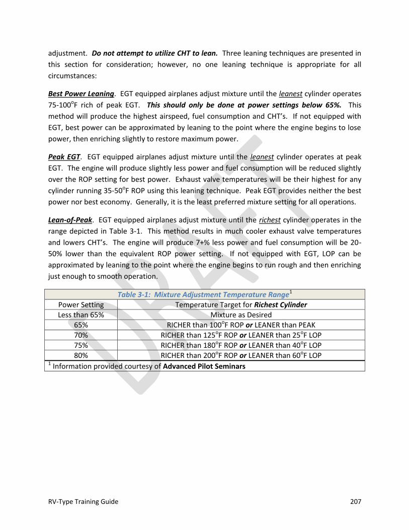
RV-Type Training Guide 207
adjustment. Do not attempt to utilize CHT to lean. Three leaning techniques are presented in
this section for consideration; however, no one leaning technique is appropriate for all
circumstances:
Best Power Leaning. EGT equipped airplanes adjust mixture until the leanest cylinder operates
75-100oF rich of peak EGT. This should only be done at power settings below 65%. This
method will produce the highest airspeed, fuel consumption and CHT’s. If not equipped with
EGT, best power can be approximated by leaning to the point where the engine begins to lose
power, then enriching slightly to restore maximum power.
Peak EGT. EGT equipped airplanes adjust mixture until the leanest cylinder operates at peak
EGT. The engine will produce slightly less power and fuel consumption will be reduced slightly
over the ROP setting for best power. Exhaust valve temperatures will be their highest for any
cylinder running 35-50oF ROP using this leaning technique. Peak EGT provides neither the best
power nor best economy. Generally, it is the least preferred mixture setting for all operations.
Lean-of-Peak. EGT equipped airplanes adjust mixture until the richest cylinder operates in the
range depicted in Table 3-1. This method results in much cooler exhaust valve temperatures
and lowers CHT’s. The engine will produce 7+% less power and fuel consumption will be 20-
50% lower than the equivalent ROP power setting. If not equipped with EGT, LOP can be
approximated by leaning to the point where the engine begins to run rough and then enriching
just enough to smooth operation.
Table 3-1: Mixture Adjustment Temperature Range1
Power Setting Temperature Target for Richest Cylinder
Less than 65% Mixture as Desired
65% RICHER than 100oF ROP or LEANER than PEAK
70% RICHER than 125oF ROP or LEANER than 25oF LOP
75% RICHER than 180oF ROP or LEANER than 40oF LOP
80% RICHER than 200oF ROP or LEANER than 60oF LOP 1 Information provided courtesy of Advanced Pilot Seminars
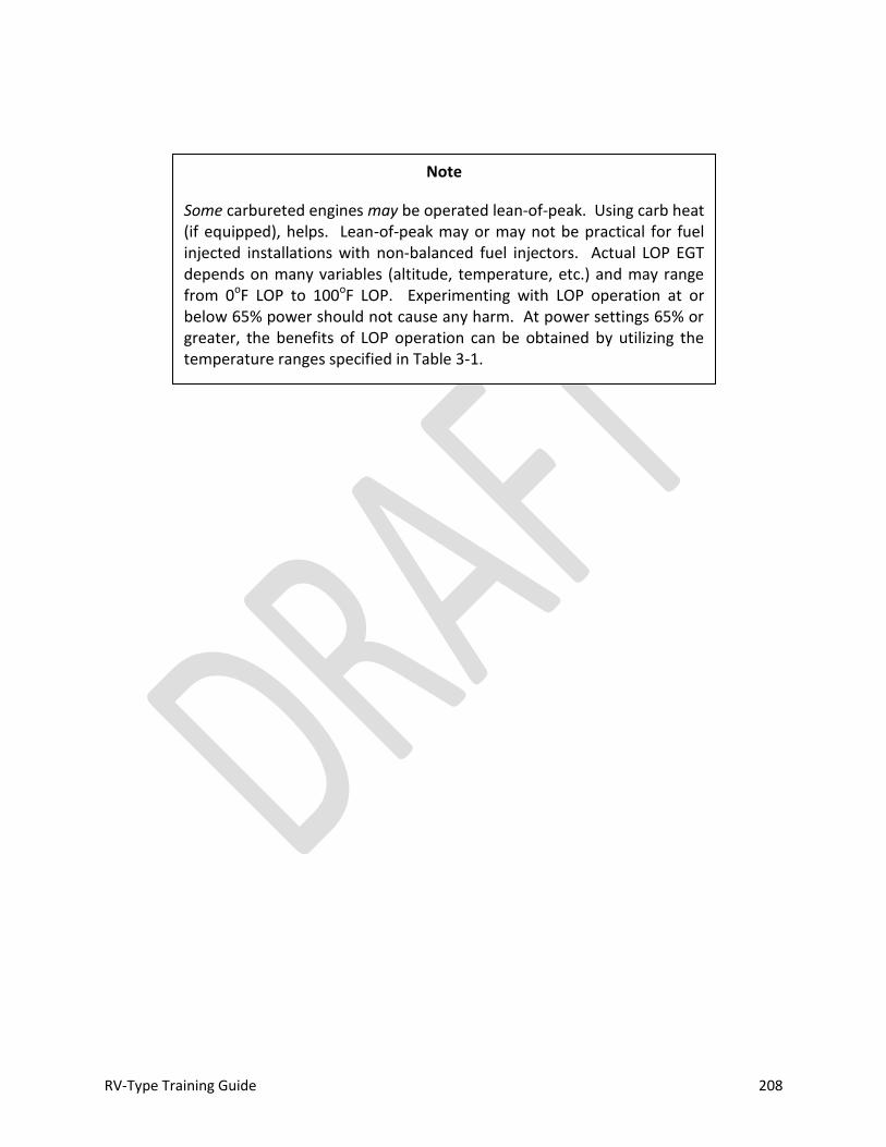
RV-Type Training Guide 208
Note
Some carbureted engines may be operated lean-of-peak. Using carb heat (if equipped), helps. Lean-of-peak may or may not be practical for fuel injected installations with non-balanced fuel injectors. Actual LOP EGT depends on many variables (altitude, temperature, etc.) and may range from 0oF LOP to 100oF LOP. Experimenting with LOP operation at or below 65% power should not cause any harm. At power settings 65% or greater, the benefits of LOP operation can be obtained by utilizing the temperature ranges specified in Table 3-1.
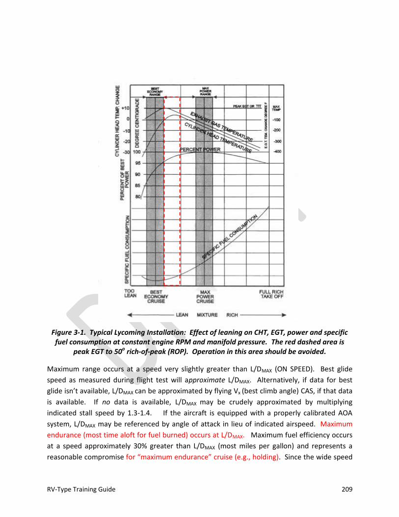
RV-Type Training Guide 209
Figure 3-1. Typical Lycoming Installation: Effect of leaning on CHT, EGT, power and specific fuel consumption at constant engine RPM and manifold pressure. The red dashed area is
peak EGT to 50o rich-of-peak (ROP). Operation in this area should be avoided.
Maximum range occurs at a speed very slightly greater than L/DMAX (ON SPEED). Best glide
speed as measured during flight test will approximate L/DMAX. Alternatively, if data for best
glide isn’t available, L/DMAX can be approximated by flying Vx (best climb angle) CAS, if that data
is available. If no data is available, L/DMAX may be crudely approximated by multiplying
indicated stall speed by 1.3-1.4. If the aircraft is equipped with a properly calibrated AOA
system, L/DMAX may be referenced by angle of attack in lieu of indicated airspeed. Maximum
endurance (most time aloft for fuel burned) occurs at L/DMAX. Maximum fuel efficiency occurs
at a speed approximately 30% greater than L/DMAX (most miles per gallon) and represents a
reasonable compromise for “maximum endurance” cruise (e.g., holding). Since the wide speed

RV-Type Training Guide 210
band of RV-types makes L/DMAX cruise generally undesirable (due to the low L/DMAX CAS), if
increased range/endurance is desired; slow down and choose a higher cruise altitude (as the
CAS will be will be lower for a given TAS).
Optimum Cruise. To approximate optimum cruise (i.e., most efficient cruise altitude), climb to
an altitude that allows for 65% power at WOT with mixture adjusted for 25o LOP. Normally, the
minimum altitude that these parameters can be met is approximately 8000 feet.
DESCENT
1. Power – AS REQUIRED
2. Mixture – AS REQUIRED
a. Note EGT at top of descent, richen during descent to maintain constant EGT or;
b. Richen for smooth operation (as required)
3. Fuel – DESIRED TANK
4. Carb Heat – AS REQUIRED (when applicable/equipped)
5. Boost Pump – ON
a. Fuel Pressure Check
6. Landing Light – AS REQUIRED
The low drag characteristics of RV-types necessitate descent planning to a greater extent than
some general aviation aircraft. A standard descent path of 2-3 degrees is generally appropriate
for cruise descent planning. Fixed pitch installations generally require a shallower descent
angle (2 degrees) than airplanes fitted with controllable pitch propellers (3 degrees). For a 3
degree descent, multiply desired altitude to lose (in thousands) by 3 to determine the distance
required for descent. For a 2 degree cruise descent, use altitude to lose (in thousands) times 4
to determine top-of-descent. Power setting will vary, depending on descent velocity desired
and ground speed. Generally, a 15-17” MAP (when equipped) starting point will work for most
airplanes. Using slightly higher power settings (19-20” MAP) and a 2 degree descent will
produce speeds near maximum structural cruising speed (top of the green arc). Speed may be
increased above maximum structural cruising speed only in calm air. It is not uncommon to
experience increasing turbulence during descent, so be prepared to slow down, as required.
Additionally, “red line” airspeed is actually true airspeed (TAS), not a fixed or indicated
airspeed. Flutter margin is decreased or eliminated at high cruising altitudes. Maximum speed
(TAS) should never be exceeded during descent operations. If there is any doubt as to flutter
margin, maintain CAS at/below maximum structural cruising speed (top of the green arc).
When appropriate for instrument planning reference, turn radius is approximately equal to 1%
displayed ground speed (when equipped) expressed as NM, assuming a standard rate turn is
RV-Type Training Guide 211
flown (3o per second). Plan 2 NM to slow in level flight from cruise speed to holding speed and
an additional NM to slow from holding speed to approach speed.
Typical Lycoming Installation, Engine Operation during Descent. As the airplane descends into
heavier air, manifold pressure will increase 1” for each 1000 feet and the mixture (set for cruise
altitude) will be maintained by the carburetor or RSA fuel servo. This relationship is fairly linear
and it is only necessary to adjust mixture slightly for smooth operation during descent. There is
no need to apply full rich mixture for descent as the fuel/air ratio is maintained from the cruise
setting. As a precaution, full rich may be selected prior to landing to provide sufficient mixture
for go-around. In the event of a go-around, full rich mixture is required for WOT operation. If
the go-around is conducted at density altitudes greater than 3000 feet, then target EGT (if
equipped) should be maintained using mixture control once established in the go-around.
LANDING PATTERN
The basic landing pattern is depicted in Figure 3-2. It may be adapted as circumstances require.
An overhead approach may be used to allow the pilot to monitor runway conditions on the
initial (upwind) leg as well as safely sequencing into the traffic flow at normal pattern altitude.
It also allows the airplane to carry significant airspeed to the break, which can be effectively
dissipated in the pitch-out to downwind. An 800-1000’ foot AGL initial leg flown at cruise speed
will ensure the airplane has sufficient energy to complete a successful engine-out pattern, if
engine stoppage occurs over or past the planned TDZ. Power setting for the break may be as
low as idle RPM. Alternatively, entry to the pattern may be flown based on ATC direction or
mid-field downwind entry. Plan a minimum of 2 NM in level flight to slow from cruise speed to
pattern speed, when appropriate. Fixed-pitch equipped RV-types will decelerate at a slower
rate than airplanes equipped with controllable pitch propellers. Regardless of pattern entry
technique (straight-in approach excepted), upgrading pilots should endeavor to fly a consistent
perch (base turn start point), adjusted for ambient wind conditions. Pattern entry should be
adjusted to arrive over the desired perch/base turn point at desired speed and configuration, as
required.
To ensure sufficient energy is available for landing if the engine fails, the base turn should be
flown to roll-out at 300’ AGL, 3000’ from the planned touchdown point (6o final glideslope). For
no-wind planning purposes, a 10:1 glide ratio can be utilized for calculations for a typical fixed-
pitch equipped RV-type. Airplanes equipped with a constant speed propeller will have a
steeper glide ratio. A standard 3o final approach may be flown, but will generally require the
addition of power. A final flown at a descent angle greater than idle glide angle provides extra
energy, generally allowing a power-off final to be flown. For short-field (maximum
performance) operations at speeds below L/DMAX, a power-on approach will be required.
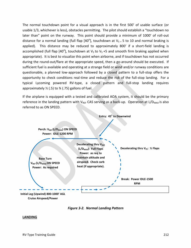
RV-Type Training Guide 212
The normal touchdown point for a visual approach is in the first 500’ of usable surface (or
usable 1/3, whichever is less), obstacles permitting. The pilot should establish a “touchdown no
later than” point on the runway. This point should provide a minimum of 1000’ of roll-out
distance for a normal landing (full flap [40o], touchdown at VS + 5 to 10 and normal braking is
applied). This distance may be reduced to approximately 800’ if a short-field landing is
accomplished (full flap [40o], touchdown at VS to VS +5 and smooth firm braking applied when
appropriate). It is best to visualize this point when airborne, and if touchdown has not occurred
during the round-out/flare at the appropriate speed, then a go-around should be executed. If
sufficient fuel is available and operating at a strange field or wind and/or runway conditions are
questionable, a planned low-approach followed by a closed pattern to a full-stop offers the
opportunity to check conditions real-time and reduce the risk of the full-stop landing. For a
typical Lycoming powered RV-type, a closed pattern and full-stop landing requires
approximately ½ (.5) to ¾ (.75) gallons of fuel.
If the airplane is equipped with a tested and calibrated AOA system, it should be the primary
reference in the landing pattern with VREF CAS serving as a back-up. Operation at L/DMAX is also
referred to as ON SPEED.
Figure 3-2. Normal Landing Pattern
LANDING
Initial Leg (Upwind) 800-1000’ AGL
Cruise Airspeed/Power
Break: Power IDLE-1500
RPM
Decelerating thru VREF
(L/DMAX): Full Flaps
Power: as req to
maintain altitude and
airspeed. Check carb
heat (if appropriate).
Decelerating thru VFE: ½ Flaps
Entry: 45o to Downwind
Base Turn
VREF (L/DMAX) ON SPEED
Power: As required
Perch: VREF (L/DMAX) ON SPEED
Power: IDLE-1200 RPM

RV-Type Training Guide 213
1. Fuel – CHECK
2. Flaps – AS DESIRED
3. Mixture – AS REQUIRED
4. Propeller—AS REQUIRED
A power off or partial power final approach is recommended for normal landings. Fixed pitch
propellers produce limited drag at low power settings, and the airplanes so equipped exhibit
outstanding glide characteristics. This glide performance must be anticipated during pattern
and landing operations to avoid a high final, excessive float and long touchdown. A constant
speed propeller offers more drag when manifold pressure is reduced and will have a lower glide
ratio than a fixed pitch equipped airplane. For normal landings, ON SPEED (L/DMAX) or VREF of
1.3-1.4 VS1 should be maintained until landing is assured. If winds are gusting, add half the gust
factor not to exceed 5 MPH / Knots (e.g., winds 15 gust 25, add 10/2 or 5). This approach speed
provides positive control, acceptable glide path and good forward visibility. It also provides
sufficient speed margin for executing a gentle flare to reduce speed for touchdown. A
stabilized final approach should be established. When flying a visual approach from a normal
pattern, plan to roll-out on final at 300’ AGL 3000’ from the planned touchdown point. Under
no-wind conditions, this will provide a 6o final descent angle. This will allow a typical RV-type to
glide to the planned TDZ in the event of power loss. Power and AOA should be adjusted during
short final to adjust descent angle and slow to approximately Vs + 10 KNOTS/MPH during the
transition to flare. Regardless of landing gear configuration, all landings require that the
airplane be flown on to the ground. For tail-wheel equipped airplanes, a full stall three point
landing is only possible if touchdown is made tail wheel first due to the length and geometry of
the main gear legs. Wheel landings with aft-swept spring gear (RV-3/4/6/7/9) require a gentle
touchdown to avoid rebounding into the air. Tail-low wheel landings may be flown in any tail
wheel RV-type. Nose wheel equipped airplanes should be landed on the main gear and the
nose should be held up as long as practical after touchdown. The low drag of the fixed pitch
propellers may result in a tendency to float during the flare proportional to airspeed carried
through final approach. RV-type elevators remain highly effective throughout the landing
phase.
Note
A stabilized approach is the key to achieving consistently good landings. Stable approach criteria should be established and agreed upon by instructors and upgrading pilots. If criteria aren’t met, then a go-around may be appropriate. The baseline criteria are on course, on glide path, on speed (VREF or AOA, as appropriate), and landing configuration (flaps) established. See Figure 3-3: EXAMPLE STABILIZED APPROACH CRITERIA.
RV-Type Training Guide 214
Common errors. One of the most common errors during landing is executing the flare too high.
RV-types have sufficient elevator authority to fully-stall, regardless of airspeed. If a full stall
occurs, the nose will drop quickly and a left roll will, likely, occur with flaps down. During
uncoordinated flight, if a stall occurs, the airplane will roll in which the direction yaw is present.
The short, low aspect ratio wings are not very responsive to ground effect. The airplane is best
flown on to the ground at a speed just above stall. Stabilize the airplane immediately above the
ground, maintain attitude and shift visual focus to the far end of the runway or beyond as the
airplane decelerates and it will settle on to the ground. For tail wheel equipped airplanes, it is
acceptable to touchdown tail wheel first. At normal landing speeds, tail wheel equipped
airplanes are still flying when touching down in a three-point attitude; transition to full aft stick
as deceleration permits. If immediate aft stick is applied at normal touchdown speeds, the
airplane will balloon back into the air. Full aft stick will provide positive control via the
steerable tail wheel and help avoid any nose-over tendencies. Brakes should be applied
cautiously to avoid over-controlling or nose-over. The technique for landing a nose wheel
equipped airplane isn’t much different—every effort should be made to touchdown main gear
first and keep the nose up as long as practical after touchdown. Another common error is to
carry excess airspeed during landing approach. A 10% increase in touchdown speed will cause a
21% increase in landing roll distance. A “touchdown no later than point” should have been
determined prior landing, and if excess speed or corrections in the flare will carry the airplane
past this point, a go-around may be safer than attempting to continue the landing. A 5 knot
tailwind component will cause a 10% increase in touchdown speed.
Note
Van’s Aircraft recommends a final approach speed of 1.3 to 1.4 VS (VREF).
If equipped (and properly tested/calibrated), AOA should be the primary reference for base turn/final and CAS should serve as a back-up.
RV-Type Training Guide 215
To use the brakes, the pilot should slide the toes or feet up from the rudder pedals to the brake
pedals. If rudder pressure is being held at the time braking action is needed, that pressure
should not be released as the feet or toes are being slid up to the brake pedals because control
may be lost before brakes can be applied. During the ground roll, the airplane’s direction of
movement may be changed by carefully applying pressure on one brake or uneven pressures
on each brake in the desired direction. If practical and available runway permits, the speed of
the airplane should be allowed to dissipate in a normal manner by friction and drag of the
wheels on the ground and use of brakes should be minimized.
Wheel Landing (Tail Wheel Equipped Airplanes). Sufficient prop/ground clearance exists for
the conduct of wheel landings. Wheel landings can be accomplished from a normal, stabilized
approach by shifting the touchdown aim point approximately 1000’ further down the runway.
After shifting the aim point, a good technique is to establish a normal flight attitude with the
gear nominally 1 foot or so above the landing surface. Reduce power and continue to fly the
airplane with primary attention on the departure end of the runway. With power reduced, the
Warning
Manual flaps may fail suddenly to the up position any time after deployment if the flap handle is not properly seated in the detent. In the event of failure, a loud bang will be noted along with increased sink rate. Stall speed will be increased instantaneously. If flaps suddenly fail to the up position, it is important to reduce pitch attitude to avoid unintentionally stalling, and to increase power smoothly to accelerate to flaps up approach speed. If flaps fail during the round-out and flare, this may mean allowing the aircraft to touchdown at a high sink rate and subsequent recovery from the bounce vs. attempting a high-power, high angle of attack recovery in the event of an aborted landing. In the event a stall is allowed to occur, the nose will drop rapidly, and may cause an unrecoverable excessive nose-low attitude.
Caution
The pilot should be alert for changing cross-wind conditions throughout the landing roll, especially when operating off a landing surface with lateral obstacles that could cause conditions to vary along the length of the landing surface.
RV-Type Training Guide 216
main wheels will settle on to the runway and forward stick may be applied after the main
wheels begin rolling to maintain a tail high attitude during deceleration. Do not relax stick
pressure prior to touchdown. The sensitive rebound characteristics of the Whitman style
landing gear (RV-3/4/6/7/9) demand precise touchdown control and early application of
forward stick will likely cause the airplane to bounce back into the air. Transition to full aft stick
as soon as the tail settles to establish positive tail wheel steering. Ailerons should be utilized
throughout the landing to assist with correcting for crosswind induced drift.
Tail-Low Wheel Landing (Tail Wheel Equipped Airplanes). The tail-low wheel landing is a
hybrid combination of both classic conventional gear landing techniques. To perform a tail-low
wheel landing, a normal three-point approach should be flown. After one or both of the mains
have touched, relax back pressure. Fly the tail on to the ground as the airplane decelerates.
The airplane is not stalled, so do not apply abrupt aft stick during deceleration. Once the tail
wheel is on the ground, full aft stick may be applied.
If attempting a tail-low wheel landing and a three-point touchdown unintentionally occurs,
continue with a normal three-point landing. Tail-low wheel landings are effective in cross-wind
conditions.
Caution (Tail Wheel Equipped RV-types)
Touchdown must occur with the longitudinal axis parallel to the direction the airplane is moving along the runway. Failure to accomplish this may impose severe side-loads on the landing gear and may cause a ground loop to occur.
Ground looping can occur at low speeds during landing roll-out. It is important to maintain proper directional control until reaching taxi speed. A loss of directional control is more likely during the deceleration phase (second half or later portion) of the landing roll out.
The airplane should never be forced onto the ground by excessive forward pressure. A transition to a three-point landing or go-around is appropriate in the event of a botched wheel landing attempt.

RV-Type Training Guide 217
Figure 3-3: Example Stabilized Approach Criteria
Short-Field Approach and Landing
The short-field approach is a maximum performance maneuver. A transition from normal
approach speed should be made so that the final portion of the approach is flown power-on,
utilizing a 3-6o descent angle. On short final (below 300’ AGL and within 3000’ of planned
touchdown), speed is reduced to VS1 +10 KNOTS/MPH. Allowance should be made for gusty
wind conditions. Add half the reported gust be added to approach speed, not to exceed 5
KNOTS/MPH total. If equipped with AOA, transition from ON SPEED to slightly slow on short
final. Touchdown will occur almost immediately after power is reduced. Flaps should be
retracted as soon as practical after touchdown and maximum braking should be cautiously
applied. For tail wheel types, a three-point landing should be flown.
Example Stabilized Approach Criteria
-Altitude. 300 feet AGL.
-Configuration. The airplane is in landing configuration (flaps set), trimmed and
power is stable.
-Heading. Tracking the extended runway centerline. This does not mean that final cross-wind correction for touchdown has been applied (Alignment), but appropriate crab is applied to track the extended centerline. -Glide path. As desired. A “standard” glide path is nominally 3o, however a glide path equal to the tested idle power glide performance will allow the conduct of a power-off approach (e.g., 6o final). Glide performance will vary from airplane to airplane for various RV-types. The type of propeller fitted will affect glide performance. -Sink rate. Stabilized commensurate with glide path. A 3o glide path requires a vertical descent rate (VVI in FPM) = 5 x ground speed. A 6o glide path requires a vertical descent rate (VVI in FPM) = 10 x ground speed. An estimated “target” VVI should be computed for approach. -Airspeed. VREF/ON SPEED +10/-0 MPH/Knots CAS. VREF = 1.3-1.4 VS1.
RV-Type Training Guide 218
Cross-wind Approach and Landing
Maximum Demonstrated Cross-wind. There is no maximum demonstrated cross wind limit for
RV-types. A skilled pilot may be able to accept 20 knots of cross wind component or more. A
more conservative rule-of-thumb is to use 20-25% of VS0 (e.g., VS0 = 55 MPH / Knots, 11-13 MPH
/ Knots maximum direct crosswind). FAR 23 certification standards require a minimum
demonstrated cross-wind component of 20% VS0. Quartering tailwinds should be avoided to
the extent practical. Consideration when selecting a landing runway should be given to steady
state winds vs. gusting winds. A steady wind is easier to handle than a variable wind. Lateral
obstacles that could cause cross wind to vary should be noted prior to landing. Pilots should
manage risk by increasing cross-wind “limits” as experience is gained. For cross-winds in excess
of 10-15 knots, consider the use of partial flaps for landing. Runway contamination (snow, ice,
standing water or wet grass) reduces surface friction and will reduce cross-wind capability.
Anticipate the degradation of aerodynamic control as speed decreases after landing.
Base Turn Adjustment. Any turn to final should be adjusted for over- or under-shooting winds
to ensure roll-out on extended centerline. In the event of an over-shoot to final, maintain
VREF/ON SPEED and coordinated flight. It is safer to accept an over-shoot than to incorrectly
apply flight controls to attempt correction that could result in unintentional stall. Initial line-up
should be in a crab to assess the magnitude of the cross-wind. The pilot should anticipate that
conditions will change as the runway is approached. Generally, cross-winds will diminish close
to the surface. As with any landing, if sufficient fuel is available and conditions permit, a
planned low-approach followed by a closed pattern allows the pilot to assess conditions and
mitigate risk during the full-stop attempt.
Crosswind Techniques. Two primary techniques may be used for cross-wind landing: a wing-
low forward slip or crab and kick.
A forward slip to landing requires the pilot to align the fuselage (longitudinal axis) with rudder
and apply aileron in the direction of the cross-wind to establish a slip. The pilot should
Caution
When operating at speeds below L/DMAX, slower speed (increased AOA) requires increased power.
Operating at low approach speed reduces the stall margin and requires proper throttle control to avoid a hard landing. If a loss of power occurs on short final, it may not be possible to reach the landing surface.

RV-Type Training Guide 219
anticipate a slight increase in descent rate and angle when applying cross-controls. Depending
on magnitude, this may require a simultaneous pitch and/or power adjustment to maintain
desired approach angle. The slip is maintained throughout the flare and landing, although it is
generally necessary to modulate control input to accommodate changing conditions as the
ground is approached. Touchdown of the upwind main gear should occur first, and the
downwind gear should be flown on to the runway.
The crab and kick method delays the application of cross-wind controls until just prior to
touchdown. Although fuselage alignment is accommodated with the rudder kick, it is still
necessary to apply aileron in the direction from which the cross-wind is blowing to prevent the
upwind wing from rising. This requirement for aileron should be anticipated by the pilot.
After landing, cross-wind controls are maintained as the airplane decelerates. It is generally
necessary to increase the inputs as the aerodynamic controls become less effective. In tail-
wheel types, some rudder authority is lost as the tail is lowered: Transition to tail-wheel or
differential brake steering, as required. Maintain positive control until the airplane is stopped.
The final portion of the landing roll (deceleration phase) presents the greatest hazard when
conducting cross-wind landings.
Tail Wheel Considerations. As the aircraft transitions to a tail-low attitude during landing roll
out, rudder effectiveness is reduced. Use of fully or nearly fully deflected flight controls during
the flare/touchdown phase may mean insufficient control authority remains when transitioning
to tail wheel steering. Loss of directional control is most likely to occur during the transition to
full tail wheel steering and during the second half (deceleration phase) of the landing roll.
Cross wind landings are practical using either a two- or three-point touchdown technique, or a
combination of the two (tail low wheel landing). If the crab method of drift correction has been
used throughout the final approach and round out, the crab must be removed before
touchdown by applying rudder to align the longitudinal axis (fuselage) with its direction of
movement. This requires timely, accurate action. Failure to accomplish this results in severe
side loads and ground looping tendencies.
The wing-low method is recommended with the transition from crab to slip on final approach.
The crosswind correction (aileron into the wind and opposite rudder) should be maintained and
adjusted as necessary throughout the round out, with touch down on the upwind main wheel.
During gusty or high wind conditions, prompt adjustments must be made in crosswind
correction to assure that the airplane does not drift as it touches down. If control becomes
marginal or drift is detected, it is usually safer to go-around than to attempt the touchdown.
Consideration should be given to selecting an alternate runway if directional control is marginal
during approach or an attempted landing.

RV-Type Training Guide 220
As forward speed decreases after initial contact, the weight of the airplane will cause the
downwind main wheel will gradually settle onto the runway. Special attention must be given to
maintaining directional control by use of rudder and tail wheel steering during the landing roll-
out while keeping the upwind wing from rising by use of aileron. Rudder effectiveness is
decreased in a three-point attitude. If rudder authority is insufficient to maintain runway
alignment during deceleration, it may be necessary to use differential braking. The airplane will
tend to weathervane into the wind as it decelerates with aerodynamic controls becoming less
effective as speed decreases. Positive control must be maintained until the aircraft comes to a
complete stop.
High Gross Weight Landing
When landing at high gross weight, fly an ON SPEED/VREF approach. Maintain ON SPEED/VREF
until landing is assured. Apply pitch inputs to establish normal landing attitude (8-10o pitch)
and airspeed desired using power to control vertical velocity (sink rate).
If the high gross weight is also accompanied by an aft CG location, the pilot should anticipate
reduced stick forces during landing. The stick force gradient (pounds of pull per G) and stick
position required for establishing AOA will change commensurate with CG location. Aft CG will
cause lighter stick forces throughout the envelope. In tandem RV-types with a CG well aft, the
pilot should apply whatever longitudinal control is required to maintain the desired 8-10o
landing pitch attitude. This may mean relaxing back pressure (or even adjusting the stick
forward) as the airplane settles into ground effect.
GO-AROUND
1. Mixture – AS REQUIRED
2. Propeller—AS REQUIRED
3. Power – ADVANCE SMOOTHLY
4. Flaps – RETRACT (airspeed increasing)
5. Trim – ADJUST
Caution
RV-types equipped with Whitman-style landing gear are susceptible to firewall and/or engine mount damage in the event of a hard landing. If a hard landing is encountered or suspected, a thorough inspection should be conducted to check for damage.
RV-Type Training Guide 221
Make the decision to go around as early as practical. Power should be applied smoothly and
sink rate should be arrested as airspeed allows. Do not attempt to adjust pitch or stop rate-of-
descent until adequate airspeed is available. Abrupt application of power at high angle-of-
attack and low airspeed will cause considerable yaw to the left. Apply right rudder in
conjunction with advancing the throttle. Sufficient power is available to arrest sink rate with
full flaps deployed. Be prepared for touchdown to occur during a go-around. As airspeed
increases, establish a normal takeoff attitude, retract flaps to the ½ (20o) position and make an
initial trim adjustment. When a positive rate of climb has been established, retract flaps fully
prior to passing VFE and adjust trim as necessary. Maintain pitch as desired to control airspeed
(8-10o pitch for normal climb).
AFTER LANDING
1. Flaps – UP
2. Boost Pump – OFF
3. Mixture – LEAN AGRESSIVELY FOR GROUND OPERATION
4. Lights – AS REQUIRED
Flaps may be retracted any time after touchdown to assist with transferring weight to the main
gear, if desired. Do not compromise directional control retracting flaps during landing roll out.
SHUT DOWN
1. Avionics – OFF
2. Lights – OFF
3. Lead Scavenging Run-up – AS REQUIRED
Lead Scavenging. Prior to engine shut-down, the engine speed should be maintained between
1000 and 1200 RPM until the operating temperatures have stabilized (thermal stabilization). At
this time, the engine should be increased to approximately 1800 RPM for 15-20 seconds, then
reduced to 1000-1200 RPM and shut-down immediately using the mixture control. A lead
scavenging run-up is generally not required if the engine is leaned aggressively for ground
operations before and after flight. As with any ground operation, monitor prop blast effect if a
Caution
If the manual flaps are retracted abruptly while airborne, it is possible for a sink rate to develop until power, AOA and airspeed can be adjusted.

RV-Type Training Guide 222
lead scavenging run-up is conducted prior to shut down. Do not conduct a run-up if prop blast
will be a hazard to aircraft, personnel, equipment or structures on the ground.
4. Mixture – IDLE CUT-OFF
5. Ignition Source – OFF
6. Electrics – OFF
TAKEOFF AND LANDING AT HIGH ELEVATION AIRPORTS
Normally aspirated engines perform and react to density altitude. For example, a typical
Lycoming engine at takeoff from an airport with an indicated altitude of 3000 feet and ambient
temperature of 85oF would be operating at a density altitude greater than 5000 feet. The
engine would lack 13-15% of its rated power (or more) and may also run rough because of a
rich mixture.
When operating from high density altitude airports (3000 feet or greater), a typical Lycoming
engine requires leaning on the ground for efficient takeoff performance. Engine roughness may
be noted if the engine is operated full rich at or above 5000 feet density altitude and wide open
throttle. The pilot can compensate for an over-rich mixture by leaning, but cannot
compensate for the loss of power as a result of high density altitude.
Approximate density altitude effects on takeoff performance can be determined by
referencing the Koch Chart. Expect approximately 75% power to be available when operating
up to a density altitude of 7000-8000 feet. Takeoff should be planned accordingly after setting
the mixture control. In addition to decreased performance, higher elevations also result in
higher TAS (and thus groundspeed) for takeoff and landing.
Ground Operations. Same as normal operation.
Takeoff. Lean to maximum RPM prior to takeoff when the density altitude is 3000 feet or
greater. Limit operation at full throttle on the ground to minimum time.
Climb. Same as normal operation.
Caution
When leaning for high density altitude operation, the engine should only be leaned enough to obtain smooth operation, not peak EGT. Detonation margin is reduced in Lycoming engines when leaning at power settings above 65%.

RV-Type Training Guide 223
Descent/Landing Pattern. Regardless of the field elevation of intended landing, the descent
from cruise altitude to traffic pattern altitude should be made with the engine leaned for
smooth engine operation. Richen slightly as required to maintain a smooth engine during
descent. To use EGT (if equipped) to assist with leaning during descent, note the EGT at the top
of descent and advance the mixture (richen) as required to maintain EGT at this value. The
exact value is not important, only relative change to the temperature noted at top of descent.
Landing at airports at or above 3000 feet density altitude, the mixture should be leaned to
maximum RPM during traffic pattern flight and landing to prevent an excessively rich mixture.
Anticipate higher than normal touchdown and roll-out ground speeds.
Go-around. Select FULL RICH and then adjust for target EGT or peak RPM.
After Landing. Same as normal operation.

RV-Type Training Guide 224
EMERGENCY PROCEDURES
One of the challenges faced by operators of EAB aircraft is development of suitable emergency
techniques and procedures. Unless prepared by the builder, no pilot’s operating handbook is
available (nor is one required under current regulations), and there is a wide variation of
equipment, power plants, propellers and system configuration even in aircraft of the same
type. In some cases, no or little specific information is available. Additionally, the quantity and
quality of test data available will vary widely. The primary consideration is that upgrading pilots
and instructors in RV type aircraft should never assume anything, unless they are familiar with
the specific aircraft to be operated.
The syllabus contains a list of emergencies that should be discussed/addressed during
situational emergency procedures training (SEPT). Unless specific checklist, handbook, and/or
flight test data is available, a generic approach may be required to assist upgrading pilots
developing necessary emergency techniques and procedures. This section addresses all of the
topics listed in the situational emergency procedures training and offers a starting point for
developing specific techniques and/or procedures that may be applicable to the RV type
operated for training. Emergencies will be addressed in phase-of-flight order: Ground
operation, takeoff, in-flight and landing. Generic checklists are provided that may be modified
at the discretion of the instructor and/or upgrading pilot and provide a starting point if aircraft
specific information is not available. Not all cases are applicable to all RV-types, and all cases
will require critical review and careful consideration by the instructor and/or upgrading pilot to
determine whether or not they may be applied to the specific RV-type operated for training,
and, if so, what modifications must be made for suitability. In any case, if specific builder’s or
manufacturer’s guidance is available, it should be followed in lieu of any information
presented in this guide.
GENERAL EMERGENCY CONSIDERATIONS
The most important step in any emergency or abnormal situation is to maintain aircraft
control. The subsequent actions are to analyze the situation, then decide on an appropriate
course of action and execute it while continuing to maintain aircraft control. It is always safer
to fly into the ground under control than to lose control under low energy conditions. If a
parachute(s) is/are worn, a timely bail-out decision should be made to exit the aircraft above
minimum computed bail-out altitude. A bail-out attempted below this altitude will increase
risk, and if the airplane is not out-of-control, it is generally safer to transition to a forced
landing. Consideration should be given to bailing out as opposed to attempting a forced
landing at night or under instrument meteorological conditions. Tail wheel equipped RV-types
are inherently unstable in a three-point configuration during ground, takeoff and landing

RV-Type Training Guide 225
operations. Regardless of gear configuration, the pilot must maintain positive directional
control at all times and make adequate allowance for prevailing wind conditions.
PRIORITIZE
Aviate, navigate and communicate—always in that order. Under no circumstances should
pilots become rushed under emergency conditions. This may take a great deal of self-control
and is best accomplished by focusing on maintaining aircraft control (including proper flying
speed/AOA) and concentrating at the task at hand. If equipped, use of an autopilot can assist
with maintaining control when accomplishing checklist or other cockpit tasks. Deliberate
action, commensurate with time available, will reduce risk and increase the likelihood of
successful outcome when dealing with abnormal/emergency conditions. Do not let someone
outside of the aircraft in which you are in command assume command of the situation (e.g.
ATC, etc). During an emergency situation, it may be necessary to tell ATC “negative, unable” if
under positive control and tell them what you your intentions are. If task management limits
your ability to accomplish anything other than maintaining aircraft control and dealing with the
emergency, then act accordingly and do not attempt to add navigating or communicating to
your current task load. Generally, once you develop a plan of action, it is best to stick with it.
SQUAWK EMERGENCY
By setting the transponder to 7700 the “communicating” step has been started with minimal
pilot action and distraction from the primary task at hand of maintaining aircraft control,
analyzing the situation and taking the appropriate action. If an off airport landing is to be
made, and the RV-type is equipped, a remote mounted ELT may be actuated via remote cockpit
switch. During training, the instructor should point out to the upgrading pilot that taking these
steps will assist with task management during a critical emergency.
LANDING
As a general rule, if landing as a result of emergency or abnormal condition is anticipated, it is
best not to pass up a suitable landing surface, when available. There may be exceptions,
notably weather considerations and availability of emergency equipment; but proximity and
suitability should always be considered carefully. The nature of the emergency will dictate
whether “land as soon as practical” or “land as soon as possible” is warranted.
Land as soon as possible. This means landing at the closest suitable landing surface as quickly
as circumstances and task loading permit. Few emergencies are so critical that landing must be
conducted as soon as possible. Examples include fire or medical emergency. Depending on the
severity of the emergency an off airport (emergency or precautionary) landing may be required.
If a generic checklist item recommends landing as soon as possible, use of a prepared landing

RV-Type Training Guide 226
surface is implied but pilot judgment may dictate an emergency and/or precautionary landing
off-field as a more prudent option. Under extreme emergency conditions, if equipped and
sufficient altitude is available, consideration should be given to bailing out in lieu of attempting
landing.
Land as soon as practical. This means landing should be conducted without undue delay, but
not necessarily as quickly as possible.

RV-Type Training Guide 227
GROUND OPERATION EMERGENCIES
EMERGENCY GROUND EGRESS (Aircraft Upright)
1. Fuel – OFF
2. Mixture – OFF
3. Ignition – OFF
4. Master Switch/Electrical Equipment – OFF
If circumstances permit, effort should be made to secure the engine and turn the fuel OFF prior
to egressing the aircraft during an emergency. Turning the master switch off will cut off power
to electrical equipment, and may reduce fire risk. Mixture should be selected to idle cut-off and
the ignition source should be selected OFF. Depending on electrical system configuration, it is
also desirable to secure the alternator switch (if so equipped).
5. Harness – RELEASE
If a parachute is warn, it is generally quicker to retain the chute during egress. To leave the
chute behind, it is necessary to un-do the leg straps and chest strap (which may or may not be
equipped with quick disconnects) and “swim out” of the parachute harness. Any headsets
should also be “jettisoned” prior to egress. The objective is to be expeditious and avoid any
sort of entanglement that could impede egress. Even in an extreme condition, it is still better
to “slow down and get there faster.”
6. Canopy – OPEN
The canopy should normally be retained throughout the egress sequence until the last step to
provide protection. If there is a passenger or second crew member, coordinate egress prior to
opening the canopy.
Aircraft flip-overs (regardless of landing gear configuration) during mishaps are not uncommon.
Be sure to consider egress options in the event of aircraft flip over, including use of canopy
breaker tools, etc. If the aircraft has come to rest inverted, releasing the harness will result in a
Warning
If there is any indication of fire, ensure both occupants are ready to egress before opening the canopy as the canopy may provide additional protection in the event of fire.

RV-Type Training Guide 228
fall. This should be anticipated and the occupants should attempt to brace to the extent
possible to preclude or minimize injury.
NO OIL PRESSURE AFTER START
If minimum oil pressure is not indicated within thirty seconds of start, shut down and
investigate.
INDUCTION FIRE DURING START (Carbureted Engines)
It is necessary to quickly analyze a fire in the induction system during the start sequence to
effectively control the situation. If there is any doubt or confusion about the nature of the fire,
or the ability to control the situation, the Fire During Ground Operations procedure should be
accomplished. Starting fires are usually the result of over-priming the engine. If equipped with
a carburetor temperature system, consider monitoring this during initial start sequence.
External Indication of Induction Fire and/or Carburetor Temperature Rapidly Increasing (if
equipped)
1. Starter – CRANK
2. Throttle – OPEN
3. Mixture – OFF
4. Fuel – OFF
Note
In cold conditions, oil pressure will be slower to initially rise after start. Specific time lag will vary as a result of lubrication system and monitoring configuration.
Caution
If the RV-type operated is equipped with an engine priming system, it is generally not necessary to prime a warm engine. Under-priming is less risky than over-priming. If the airplane is not equipped with a priming system, caution should be exercised when utilizing the accelerator pump in the carburetor to assist with start. Excessive throttle “pumping” should be avoided.

RV-Type Training Guide 229
If the pilot determines a fire in the carburetor is likely, it is preferred that the starting sequence
be continued in an effort to draw the excess fuel into the induction system. If the engine hasn’t
started, select the mixture to idle cutoff and open the throttle while continuing to crank. If the
engine starts, it will run momentarily on residual fuel and pull the fire into the induction
system. If the engine has already started, continue to operate long enough to pull the fire into
the engine. In either case, if evidence of fire persists or if in doubt:
5. Ignition – OFF
6. Master Switch/Electrical Equipment – OFF
7. Ground Egress
Carburetor Temperature Considerations (if equipped). Prior to start, the temperature
displayed will be the temperature of the carburetor body. If the engine becomes flooded and
fuel starts to drip from the carburetor, the unit may display a drop in carburetor temperature
as the fuel starts to evaporate. If the engine backfires and fire starts in the venturi, the unit will
display a rapid rise in carburetor temperature. Check the manufacturer’s technical information
for the behavior of displayed carburetor temperature in the event of induction fire for specific
information.
BRAKE MALFUNCTION
The most likely cause of a brake malfunction is a hydraulic fluid leak or air in the system causing
a lack of braking action. The left and right brake systems are independent (each pedal is
equipped with a master cylinder), but may share a common reservoir. Lines are fitted from the
master cylinders in the cockpit (mounted on/connected to the pilot’s rudder pedals) to the
brake actuators on each main wheel. When working normally, each pedal should provide good
resistance when depressed. A spongy pedal or one that rotates forward freely indicates a lack
of fluid or presence of air on that side.
Brake malfunction may be caused by a malfunctioning wheel brake assembly. The calipers on
the main wheels are designed to float, and damage to the caliper, disk or interference can
result in abnormal caliper movement and cause a dragging brake. Without cross-wind, the
airplane should track straight on the ground. Any turning tendency not attributed to cross-
wind should be investigated.
Brakes should be checked prior to start (pedals equally firm, depressed an equal amount) and
immediately after start. A “brake check” should be conducted prior to taxi (momentarily
release the brakes and re-apply at very low speed). If at any point, abnormal or lack of braking
action is noted, the following procedure should be applied:
1. Stick – MAINTAIN FULL AFT
RV-Type Training Guide 230
2. Tail Wheel/Rudder Steering – AS REQUIRED
3. Mixture – OFF (If required)
4. Fuel – OFF (If required)
For tail wheel equipped airplanes, full aft stick will supply maximum tail wheel traction and
increase steering effectiveness. For nose wheel equipped aircraft, any residual brake capability
may assist with differential steering. If a loss of braking action is encountered, reducing power
and turning off the engine will limit forward velocity. The tail wheel steering, rudder steering or
residual differential braking may be used to generate a controlled ground loop rather than
colliding with a hazard.
Brake Fire. In the event of a brake malfunction or if excessive braking is applied, brake
overheating, and potentially fire, may be encountered. A brake fire may not be immediately
apparent as the landing gear is not visible from the cockpit. A brake fire occurs when a brake
assembly overheats, a caliper O-ring or other component fails (e.g., b-nut, solid line crack, etc.)
and may be exacerbated if brake fluid is present (i.e., the hydraulic fluid may begin to burn
when its flash temperature is exceeded). Other combustibles in the landing gear assembly
include tires, wheel pant and fairing assemblies. A primary danger associated with a brake fire
is proximity to the fuel tanks, including quick drains and vents which can be a source of raw fuel
in the event of a leak or fuel expansion. If a brake fire is suspected, the airplane should be
stopped and an emergency ground egress should be considered.
Caution (Tail Wheel Airplanes)
In general brakes shouldn’t be used to control yaw for the purpose of taxi, takeoff or landing. They should be used at minimum speed or in the event that aerodynamic control is in doubt. Caution should be exercised if the rudder is deflected and it becomes necessary to simultaneously apply brake. If this is the case, it is necessary to maintain rudder pressure while sliding your toes up the rudder pedal. Under some conditions, even a momentary relaxation of rudder to allow brake use may be sufficient to cause a loss of directional control.
RV-Type Training Guide 231
FLOODED ENGINE DURING START
Follow the engine manufacturer’s recommendations for starting a flooded engine. Unless a
malfunction exists, the key is to avoid flooding in the first place. Avoid the tendency to over-
prime, or, if equipped with a carburetor, excessive use of the throttle actuated accelerator
pump. A fuel odor may be noted during a flooded start. If flooding occurs and time permits,
wait for the excess fuel to evaporate and then attempt re-start. This technique will minimize
engine wear and is the single best way to ensure induction fire risk is reduced and likelihood of
normal start is increased. If it is necessary to continue with the start and sufficient time is not
available to allow excess fuel to evaporate, and specific engine manufacturer’s guidance is not
available, select the mixture control to idle cut-off, open the throttle and crank. When the
engine starts, immediately reduce power, advance the mixture control and continue with a
normal warm-up. Be alert for signs of induction fire during a flooded start attempt.
FIRE DURING GROUND OPERATIONS
The following procedure may be applied for any type of fire when operating on the ground. It is
not necessary to ascertain the type or source of the fire when operating on the ground. Prompt
action to secure the engine, fuel supply and electrical system prior to egress is the only action
required.
1. Fuel – OFF
Turning the fuel supply OFF will result in engine stoppage. At low power settings typically
associated with taxi considerable amounts of “residual fuel” will remain after the fuel valve is
selected off (e.g., the engine will continue to run for some time at idle power after the fuel
valve is turned OFF). Residual fuel amounts will vary from airplane to airplane and are easily
tested by securing the fuel valve with the engine at IDLE and using a stop watch to determine
subsequent run-time. It is not uncommon for RV types to have over 1 minute and 30 seconds
of residual fuel at IDLE power.
Caution
Do not over-prime (if equipped).
Do not exceed starter limitations when attempting to start a flooded engine: individual starter and/or engine manufacturers will specify starter limitations. In general, cranking attempts should be limited to 10 seconds with sufficient cool-down between attempts.
RV-Type Training Guide 232
2. Mixture – OFF
If prompt action is taken to proceed with step 2 (Mixture – OFF), then it is likely that some fuel
will remain in the lines before it has been drawn into the induction system or has a chance to
burn. Selecting the mixture lever to idle cut-off is generally the quickest means to safely shut
down the engine under all conditions. Do not delay selecting the mixture to the idle cut-off
position in an attempt to allow residual fuel to burn out.
3. Ignition – OFF
If properly installed and functioning, turning the ignition source OFF will also cause the engine
to shut down. A switch malfunction or wiring problem (e.g., failed p-lead for a conventional
magneto equipped engine) may allow the engine to continue to operate if the fuel supply to
the engine is not shut off.
4. Throttle – OPEN
5. Master Switch/Electrics – OFF
Turning the master switch(s) OFF (if equipped and installed correctly) will cut off power to all
electrical equipment. If time is critical, electrics may be ignored during the emergency ground
egress sequence.
6. Ground Egress
If a fire extinguisher is available, it is recommended that if circumstances permit, the pilot
should consider its use.
TAILWHEEL EQUIPPED AIRPLANES: LOSS OF DIRECTIONAL CONTROL (GROUND LOOP)
A ground loop is an uncontrolled turn during ground operation that may occur while taxiing or
taking off but is most prevalent during the deceleration phase of the landing roll out. It is not
always caused by drift or weathervaning, although this may cause the initial swerve. Careless
use of the rudder (or brakes), an uneven ground surface, or a soft spot that retards one main
Warning
A cockpit-mounted, hand-held fire extinguisher (if available) may be of limited or no use against a well-developed fuel fire. If a fire continues to burn, an explosion may occur. If in doubt after exiting the aircraft, the crew should move as rapidly as possible to a safe distance away from the burning aircraft.
RV-Type Training Guide 233
wheel of the airplane may also cause a swerve. Generally, the initial swerve tends to cause the
airplane to ground loop.
Since the airplane is unstable directionally on the ground, the forces that cause a ground loop
increase as the swerve increases. The initial swerve develops inertia and this, acting at the CG
(located behind the main wheels), swerves the airplane even more. If allowed to develop, the
force produced may become great enough to tip the airplane until one wing strikes the ground.
If the airplane touches down while drifting or in a crab, the pilot should apply aileron toward
the high wing and stop the swerve with the rudder. Brakes should be used only when rudder is
inadequate, and care must be taken to move the foot up the rudder pedal to apply brake
without taking out the rudder input. Caution must be used when applying brake, because it is
easy to over-control and aggravate the situation. If brakes are used, sufficient brake should be
applied on the low-wing wheel (outside of the turn, opposite the direction of swerve) to stop
the swerve. When the wings are approximately level, the new direction must be maintained
momentarily (zero yaw rate) until correction can be applied. After yaw rate is stabilized, use
caution not to over-correct. If sufficient runway is available, adding full power and taking off
may be the safest course of action since full power substantially increases rudder authority. If
sufficient runway is not available, a momentary burst of power may still be appropriate to assist
with increasing rudder authority.
TAKEOFF EMERGENCIES
LOSS OF DIRECTIONAL CONTROL
1. Throttle – IDLE
2. Stick – FULL AFT
3. Brake – AS REQUIRED
4. Yaw Rate – STABILIZE
REJECTED TAKEOFF/TAKEOFF ABORT
In general, if sufficient runway remains, it is desirable to reject/abort takeoff rather than
attempt flight with degraded systems or engine. For minor system malfunctions, it is generally
safer to takeoff, climb to a safe altitude, analyze the situation and take appropriate action
rather than attempting a high-speed reject/abort. For Day/VMC operations, the pilot should
consider rejecting/aborting the takeoff if there is an engine malfunction, directional control is in
doubt, airspeed system failure occurs or a runway hazard exists. Good acceleration
performance results in a brisk takeoff roll, so reaction time for rejecting/aborting the takeoff is
RV-Type Training Guide 234
limited. In the event the pilot decides to discontinue the takeoff, the following procedure
should be applied:
1. Throttle – IDLE
2. Stick – TRANSITION TO FULL AFT AS AIRSPEED ALLOWS
For tail wheel equipped airplanes, the pilot needs to use caution while applying aft stick as
rapidly as deceleration permits due to elevator effectiveness. If the tail has already been raised
or at high speeds in the 3-point attitude, there is sufficient elevator authority to lift the nose if
full aft stick is applied too quickly. Conversely, failure to apply aft stick in a timely manner will
not transfer as much weight as practical to the tail wheel and will limit steering effectiveness.
3. Directional Control – MAINTAIN
As with any high-speed situation on the ground, maintaining proper directional control is of
primary importance. Tail wheel equipped airplanes are directionally unstable on the ground,
particularly in a 3-point attitude. Regardless of gear configuration, in cross-wind conditions, use
of aileron to assist in drift control will likely be required. The light weight, low wing loading and
vertical surface volume of RV-types makes them susceptible to upsets in gusty wind conditions.
The pilot must react to gust effects and should be cautious when operating on a runway under
cross-wind conditions with structures on the upwind side of the runway that may cause
turbulence. Gusts will affect directional control throughout the deceleration phase and will
continue to effect control even at taxi speeds.
4. Brakes – APPLY
Brakes should be applied cautiously and only when required to ensure stopping or maintain
directional control. A rapid application of brake at high speed can result in a nose-over and/or
flip over. Misapplication of differential braking can result in a swerve and/or loss of directional
control.
ENGINE FAILURE/MALFUNCTION DURING OR IMMEDIATELY AFTER TAKEOFF
Pilots should be prepared for the possibility that the engine will lose partial or total power
during the take-off and climb-out; or at any other time during flight. If there is even a suspicion
something is not quite right during the initial ground run or the engine falters (even if it
subsequently picks up), and sufficient runway is available, the reject/abort procedure should be
applied. A take-off should not be attempt if the pilot is not fully confident about engine
behavior or aircraft/systems performance.

RV-Type Training Guide 235
Power Loss during Takeoff Roll
1. REJECT/ABORT
2. Fuel – OFF
Ergonomic consideration. Depending on cockpit configuration and equipment, it may not be
possible for all pilots to reach the fuel valve in all airplanes if the shoulder straps are properly
tight. Unless sufficient time exists to allow the pilot to properly tighten the straps before
touchdown, omit step 2 above and proceed to step 3 below:
3. Mixture—OFF
4. Ignition—OFF
5. Master Switch/Electrics – OFF
6. Ground Egress (If Required)
Power Loss Immediately After Lift-off
1. Land Straight Ahead
2. Fuel – OFF
Ergonomic consideration. Depending on cockpit configuration and equipment, it may not be
possible for all pilots to reach the fuel valve in all airplanes if the shoulder straps are properly
tight. Unless sufficient time exists to allow the pilot to properly tighten the straps before
touchdown, omit step 2 above and proceed to step 3 below:
3. Mixture – OFF
4. Ignition – OFF
5. Master Switch/Electrics – OFF
On-field Landing Considerations. When total or near-total power loss occurs after lift-off it is
imperative to maintain positive control and safe flying airspeed. This initially implies either
immediately transitioning to landing or quickly and smoothly getting the aircraft into the right
glide attitude, allowing airspeed to stabilize as desired and trimming to maintain a stable
AOA/airspeed condition. If the airplane has already reached climb speed, the low-drag and
good glide characteristics of RV-types may allow some zoom capability, if desired. If an
immediate landing is attempted, these same characteristics will cause floating as the AOA is
increased during deceleration. Avoid obstructions and be prepared for a heavy landing and,
possibly, the need to perform an intentional ground loop in lieu of hitting obstacles. A slightly
fast landing and intentional ground loop may be preferable to attempting a tail-low full-stall
landing and catching the gear on an obstacle (perimeter fence, etc.). The amount of time to
RV-Type Training Guide 236
react will be very limited, and once a course of action is selected, it’s generally best to continue
on the course rather than risk loss of control as a result of indecision.
Power Loss at Low Altitude (e.g., Below 1500 Feet AGL, Below Minimum Safe Turn-back
Altitude, Below Minimum Controlled Bail-out Altitude, etc.)
1. Glide – BEST RANGE or MINIMUM SINK SPEED
2. Landing Site – SELECT
3. Auxiliary Boost Pump – CHECK ON
4. Fuel Selector – SWITCH TANKS
If no restart is obtained
5. Fuel – OFF
6. Mixture – OFF
7. Ignition – OFF
8. Master Switch/Electrics – OFF
9. Should Harness – TIGHTEN
10. Airspeed – MAINTAIN
11. Anticipate Forced Landing
Off-field Landing Considerations. When transitioning from climb to glide attitude, the nose
may have to be pushed down. Due to the high climb angles that RV-type aircraft are capable of
generating, this may feel excessive if the aircraft was trimmed for a nose high, slow climb
speed. A rule of thumb that may be helpful is “angle equals angle,” in other words, if climbing
out at 10 degrees nose up, initially transition to 10 degrees nose low until airspeed stabilizes or
increases, as desired. Depending on pilot reaction time and initial attitude, airspeed may decay
during the transition. At low climb speeds and aft CG loadings, RV-types exhibit fairly light stick
forces and reduced static margin, so smooth positive control is required to set the proper pitch
angle for glide AOA. Set speed/AOA for maximum endurance or range, as desired. Trim.
Warning
Primary attention must be on maintaining proper aircraft control in the event of power loss at low altitude. Minimum time exists to troubleshoot a malfunction or attempt corrective action. It is always safer to accomplish a forced landing under control than it is to lose control due to channelized attention and/or task saturation. The highest priority in this situation is to maintain sufficient flying speed/AOA.

RV-Type Training Guide 237
If some energy (altitude and/or airspeed for zoom) is available, but there is no possibility of
landing on the airfield, then an off-field landing is mandatory. Analyze the area ahead and to
the sides. If sufficient energy exists, it may be practical to maneuver to a better site or avoid
obstacles by using a 30o, 45o or even 60o of heading change at moderate bank angles. Bank
angle should be proportionate to airspeed: low airspeed = limited bank. Wind direction should
be considered, and if in doubt land into the wind in an area with minimum obstacles.
Do not choose a site at a marginal distance. Close is better—available energy can be used for
maneuvering to the best approach position. Adequate altitude can compensate for
misjudgment, adverse wind shift, sinking air, vertical gust and other unforeseen events. This
altitude can be compensated for by use of flaps and sideslip.
Warning
Side slip with full flaps can cause high sink rates. Safe airspeed should be maintained throughout maneuvering and the sink rate should be arrested before touchdown.
Bail-out below computed minimum controlled bail-out altitude is not recommended and carries higher risk than a forced landing attempt.

RV-Type Training Guide 238
IN-FLIGHT EMERGENCIES
ELECTRICAL MALFUNCTION
Low Amperage Condition (Conventional System Configuration)
One of the most common in-flight electrical malfunctions is the failure of the charging system
(e.g., alternator). This could be caused by a mechanical fault, a belt failure (if equipped),
regulator malfunction, internal electrical malfunction within the alternator, or other wiring
problem. Although not likely, alternator failure can also be caused by over-heating. In the
event of charging system failure, all components will be powered by the main aircraft battery.
Many modern avionics components (e.g., EFIS displays, AHRS, etc.) may also include an internal
Caution
Failure to detect a charging system failure in a timely manner may cause unintentional depletion of the battery and total DC electrical failure without warning in some aircraft.
Exact operating time for batteries cannot be assured, nor should exact times in manufacturer’s data should be assumed. In the event of electrical malfunction, the pilot should, generally, land as soon as practical.
Note
There is more variation amongst electrical/avionics systems than any other RV-type sub-systems. Each aircraft should be treated as unique in this regard and proper understanding of the electrical system as installed is imperative for safe operation of the aircraft. If a handbook or builder’s data is not readily available, ensure adequate research is conducted to develop sufficient knowledge of system operation under both normal and emergency conditions. Depending on circumstances, instructors may need to assist upgrading pilots.
3 basic emergency conditions are presented for consideration: High and Low Amperage conditions and Electrical Fire. There may be other malfunctions pertinent to the specific aircraft to be operated for training not addressed.

RV-Type Training Guide 239
battery, independent of the primary electrical system(s) that will function in the event of a
complete electrical failure. It is necessary to consult component equipment manufacturer’s
data to determine specific system voltages and battery capacities. In any case, depending on
equipment and electrical system configuration, establish the means of determining that the
charging system has failed. Develop a technique or procedure for load shedding if a checklist
does not exist and become familiar with the means to utilize any internal back-up battery
capacity available in installed equipment. An electrical load analysis should be performed or
component manufacturer’s literature should be consulted to determine length of aircraft
battery power time and any additional back-up power available.
1. Load—SHED
2. Battery Voltage(s)—MONITOR (if equipped)
3. Establish VMC (if practical) and anticipate battery failure
High Amperage Condition (Conventional System)
A high amperage condition is less likely than a low amperage condition. If the voltage regulator
is properly adjusted and the over-voltage relay is working normally (upper limit contacts open),
the most likely cause of a high amperage condition is either a faulty regulator, a shorted cell in
the battery or a loose/broken ground wire between the regulator and the alternator. If a high
amperage condition and high voltage (generally greater than 14.5 volts in a 12-volt system)
exist simultaneously, the battery has suffered an internal short. This condition may be cyclical.
If this occurs, consideration should be given to isolating the battery and not attempting power
up any equipment unless required for continued safe flight. If a back-up power source is
available, it should be utilized.
1. Charging Source—OFF
2. Avionics—OFF
3. Electrical Equipment and Avionics—AS REQUIRED FOR SAFE FLIGHT (load shed)
4. System Voltage/Amperage—MONITOR (if equipped)
5. Establish VMC if practical and anticipate battery failure
Caution
Electronic equipment is most sensitive to an over-voltage condition and it should, generally, be secured as rapidly as possible to avoid damage through the most expeditious means practical (e.g., avionics master switch, etc.).
RV-Type Training Guide 240
ELECTRICAL FIRE
The initial indication of an electrical fire is usually the distinct odor of burning insulation. If an
electrical fire is suspected, the pilot should attempt to identify the faulty circuit by checking
circuit breakers, instruments, avionics and lights. If smoke, fumes or other evidence of
electrical fire persist:
1. Electrics—OFF (e.g., master switch, battery etc.)
2. Charging Source—OFF
3. All Switches—OFF
4. Cabin Heat and Vent—OFF
If Fire Persists
5. Anticipate Forced Landing or Bail Out
VMC Fire Extinguished
5. Cabin – VENTILATE
6. Remain VMC and Land as soon as possible
IMC / Night Fire Extinguished
At night or under instrument conditions, electrical power may essential for emergency
continuation of the flight long enough to attempt landing if bail-out is not practical. In this case
the following procedures should be applied. When powering up required equipment, the pilot
should begin by restoring systems which are equipped with internal back-up batteries (e.g.,
attitude source, GPS, etc.). Next in priority is equipment powered by the aircraft battery.
Required systems should be powered up one at a time. When powering up systems, the pilot
should pause and check for signs of odor, smoke or sparks before proceeding to the next
system. Only the minimum systems required for safe flight should be powered up.
5. Cabin—VENTILATE
Warning
Any materials ignited by the initial fault may continue to burn after power is secured. Ventilating the cabin may increase likelihood of open flame developing. If toxic odor is suspected, the pilot will need to make a determination which poses a greater risk.

RV-Type Training Guide 241
6. Required systems powered by internal battery—ON
7. Battery (e.g., master switch, etc.)—ON
8. Electrical Equipment—AS REQUIRED (One system at a time)
9. Battery Voltage—MONITOR (if equipped)
10. Charging Source—AS REQUIRED
11. Land as soon as possible
OIL SYSTEM MALFUNCTION
An oil system malfunction is recognized by drop in oil pressure, a complete loss of pressure, or
excessive oil pressure with or without abnormal oil temperature indications. A steady rise in
temperature accompanied by a drop in pressure is a particular sign of engine lubrication system
trouble. Cross-check CHT reading(s) (if equipped) to validate oil temperature trend.
A wide variation in engine monitoring systems and indicators will be encountered throughout
the RV fleet. Oil temperature and pressure indicators of some type are required for air cooled
engines by FAR, so all conventionally powered RV-types should have at least minimal
indications. Additional annunciator lights, warnings, etc. are not required; so in a basic
installation, mechanical (or electric) gauge readings may be the only information available to
monitor the proper functioning of the oil system. In this case, failure to monitor the gauge
could result in system failure without warning.
For aircraft not equipped with an inverted oil system, oil venting under negative G conditions
will occur. Venting occurs through the crankcase breather (conventional Lycoming power
plant) and begins at approximately zero G. The amount of oil lost is proportional to the
magnitude and duration of negative G load. Venting can occur quickly, even in the event of a
short excursion. Slip stream effects may carry oil to any part of the airframe, including the
canopy.
Oil temperature is inversely proportional to oil volume. As the amount of oil in the engine
decreases, oil temperature will increase. Cockpit indications of low oil quantity are decreased
oil pressure and increased oil temperature. The relationship between temperature and
pressure behavior may assist the pilot in making a determination whether an oil system
malfunction exists or there is an indicator problem. The pilot should assume an oil system
malfunction exists if in doubt. Continued operation with a known bad indicator should be
avoided.
Consult engine manufacturer’s or builder’s data for oil temperature and pressure limits. It may
be necessary for instructors to assist the upgrading pilot with proper operation of engine
monitoring systems (if equipped).
RV-Type Training Guide 242
Although the full-flow FAA-approved aircraft filter (when equipped), oil cooler and suction
screen are fitted with bypass features that allow remaining oil to circulate in the event of
blockage, a mechanical or fitting/component failure can result in loss of engine oil. A partial
loss of oil pressure may be an indication of a regulation problem. High oil temperature may be
due to decreased oil level, obstruction in the oil cooler (internal or external), damaged baffle
seals, a defective gauge or other causes. Depending on the nature of the malfunction, if oil is
being lost, the process of may be gradual or rapid. The engine will continue to run for an
undetermined period of time until all oil has been lost and seizure occurs.
In the event an oil system malfunction occurs, maintain minimum practical power, avoid high
and/or negative G forces and unnecessary throttle movements; and land as soon as possible.
Be prepared for imminent engine failure.
1. Power—MINIMUM PRACTICAL
2. Anticipate Engine Failure
ENGINE MALFUNCTION
Two common causes of engine malfunction are interruption of fuel flow or roughness/power
loss due to induction system (carburetor) icing. Complete power loss is usually due to fuel
interruption. If this is the case, power will likely be restored when fuel flow is restored. Select
the appropriate glide speed and a suitable emergency landing location while attempting to
restore power by completing checklist actions. If an unexplained decrease in performance is
noted (airspeed/RPM/manifold pressure), full carburetor heat (if equipped) or alternate air
should be selected and carburetor temperature should be monitored (if appropriate and
equipped). Do not delay application of carburetor heat or alternate air source if in doubt. If ice
is present and carburetor heat begins to melt it, a further decrease in power and increased
roughness may be noted, indicating that the water from the melted ice is being moved through
the engine.
If attempting to restore fuel flow or carburetor heat has no effect, a rough engine can also be
caused by an improper mixture setting. If the mixture is unintentionally too rich or too lean,
engine roughness will result. Switching fuel tanks may mitigate roughness caused by fuel
Note
For a typical Lycoming installation, carburetor icing is not likely at high (>75%) power settings or when outside air temperature is 14oF or cooler.
RV-Type Training Guide 243
contamination. If the left or right magneto/ignition source provides adequate operation at
reduced power with mixture rich, proceed to the nearest suitable airfield and land as soon as
practical.
Sudden engine roughness or misfiring may be result of an ignition problem. Switching one
ignition system off in turn will identify which one is malfunctioning. Select different power
settings and richen the mixture to determine whether continued operation on one or both
systems is possible. If the engine quits completely when selecting Left or Right ignition source,
pull the mixture control to idle cut-off, wait ten seconds, select the good ignition source and
advance the mixture control to re-start the engine. This procedure will prevent backfire.
Engine Failure / Loss of Power
1. Glide—MAXIMUM RANGE or MINIMUM SINK
2. Landing Site—SELECT
3. Fuel Quantity—CHECK
4. Engine Instruments—CHECK
5. Boost Pump—ON
6. Fuel Valve—AS REQUIRED
7. Mixture—AS REQUIRED
8. Carb Heat/Alternate Air Source—AS REQUIRED
9. Ignition Source—CHECK LEFT / RIGHT / BOTH
10. Primer (if equipped)—LOCKED
If Engine Fails to Start
11. Fuel—OFF
12. Mixture—IDLE CUT-OFF
13. Ignition Source—OFF
14. Charging Source—OFF
15. MAYDAY Call (if time/circumstance permit)
16. ELT—ON (if remote cockpit control is available)
17. Electrics—OFF
18. Shoulder Harness—SECURE
19. Airspeed/flying AOA—MAINTAIN
20. Anticipate Forced Landing or Bail Out
Engine Fire
An in-flight engine compartment fire is usually caused by a malfunction of the fuel or oil
systems. This may be caused by a mechanical failure of the engine itself, an engine-driven
RV-Type Training Guide 244
accessory, a defective induction or exhaust system, a malfunctioning fuel-delivery system
(carburetor or fuel injection system component), a broken line, hose or loose connector.
Engine compartment fires can be indicated by smoke and/or flames coming from the engine
cowling area. They can also be indicated by discoloration, bubbling and/or melting of the
engine cowling in cases where smoke or flames may not be visible. Abnormal cockpit
temperature or flames and/or smoke coming through the cabin ventilation system may also
indicate a fire is present. By the time the pilot becomes aware of an in-flight engine
compartment fire, it is usually well developed.
1. Fuel—OFF
2. Mixture—IDLE CUT-OFF
3. Charging Source—OFF
4. Ignition Source—OFF
5. Throttle—IDLE
6. Cabin Heat and Vent—CLOSED (if applicable)
7. Airspeed to Extinguish—DIVE AS REQUIRED
8. Glide (if/when appropriate)—MAXIMUM RANGE / MINIMUM SINK
If the fire is oil-fed, thick black smoke will be present, as opposed to a fuel-fed fire (which
produces bright orange flames). For fixed pitch propeller equipped aircraft, the pilot should
consider stopping the propeller rotation by raising the nose and slowing the airplane after the
engine is secured. This procedure will stop an engine-driven pump from continuing to pump
flammable fluid which is feeding the fire. To accomplish this, the pilot must quickly stall the
airplane and smoothly re-establish a high speed dive in an attempt to blow out the fire.
Stopping a controllable speed propeller can be problematic. If there is any doubt, it is best to
increase dive speed immediately and not be concerned with propeller rotation.
9. MAYDAY CALL (if time/circumstances permit)
10. ELT—ON (if remote cockpit control is available)
11. Electrics—OFF
Unless a fire is electrical in nature, turning off the electrical equipment (e.g., master switch)
should be delayed to allow for communication and emergency transponder squawk during the
emergency.
12. Anticipate Forced Landing or Bail Out
RV-Type Training Guide 245
PITOT/STATIC MALFUNCTIONS
Indication of Pitot Blockage. The pitot tube is particularly sensitive to blockage, especially by
icing. Even light icing not visible from the cockpit can block the entry hole of the pitot tube.
This will affect the ASI and any advanced systems that utilize pitot input (e.g., AHRS, EFIS etc.).
If the RV-type is equipped with advanced instrumentation, airspeed indications may revert to
GPS ground speed. If the pitot tube becomes blocked, the mechanical ASI (and pitot portion of
the EFIS, if equipped) displays inaccurate speeds. How the airspeed indication will be effected
depends on the type of pitot tube fitted and configuration of the pitot system. If the airplane is
fitted with a simple pitot tube (e.g., a bent stainless or aluminum tube) without any sort of
drain, at the altitude where the pitot tube becomes blocked, the ASI may remain at the existing
airspeed and won’t reflect actual changes in speed. If altitude changes are made with a blocked
pitot tube, the ASI may behave like an altimeter in this case. If the airplane is fitted with a pitot
tube that has a drain, indicated airspeed may bleed to zero in the event of blockage (depending
on whether or not the drain remains clear). If the airplane is equipped with advanced
instrumentation, the first sign of pitot icing may be reversion to GPS ground speed. If the RV-
type operated has advanced instrumentation, the upgrading pilot should be familiar with
reversion cues/warnings. Regardless of the cause of blockage, failure of indicated airspeed in
flight can be insidious and can be only be verified by proper cross-check of other instruments.
The most common cause of pitot malfunction is failing to remove the pitot tube cover before
flight. The pitot tube on most RV-types is not visible from the cockpit. If the “malfunction” is
simply a cover left in place, this should be detected during initial takeoff roll at approximately
25-30 knots. If airspeed is “not off the peg” as the airplane accelerates, consideration should
be given to aborting/rejecting the takeoff.
If erroneous airspeed indications are suspected in flight, cross-check available instrumentation
to assist with maintaining aircraft control (e.g., AOA or GPS derived ground speed). If equipped
properly functioning and calibrated, AOA is always a suitable substitute for indicated airspeed.
Depending on system configuration, however, AOA indications may or may not be correct
(especially systems that share a single pitot tube). In the event pitot blockage is suspected, the
best course of action is to apply a known pitch and power setting to obtain desired
performance.
Warning
No attempt should be made to restart a secured engine after a fire.

RV-Type Training Guide 246
Table 3-2: Example Pitch/Power Settings1
Pitch Power
Cruise Climb +3 to +5o WOT
Level Cruise 0 to +1o 55-75%
Cruise Descent -2 to -3o 15” MAP
Approach -3o (VVI = GS x 5) 12-13” MAP 1Actual pitch and power settings for a specific RV must be determined by flight test.
Indication of Static Blockage. While less common that pitot blockage, static blockage may also
occur. The most common cause of static blockage is liquid water trapped in a static line that
subsequently freezes. Some aircraft may be equipped with an alternate static source. If the
airplane is equipped with conventional mechanical pitot/static instruments of any type (e.g.,
airspeed indicator, altimeter, or VVI), whether primary or back-up, breaking the glass on any of
these instruments will provide an alternate static source. Traditionally, the VVI is the “least
dear” of these instruments (if equipped).
The trapped pressure in the static system causes the altimeter to remain at the altitude where
the blockage occurred and the VVI will remain at zero. If normal pitot is still available, the
airspeed indicator continues to operate, but is inaccurate. The CAS will be lower than actual if
the airplane climbs above the altitude at which the static block occurred, and will be higher
than actual if the airplane descends. To restore airspeed, altimeter and or VVI functions with
blocked static ports, the pilot should select the alternate static source or break the glass on a
pitot static instrument (e.g., VVI). Use of an alternate static source will affect the accuracy of
Warning
Airframe, pitot icing or other blockage may cause a loss of pitot pressure. Exact behavior of indicated airspeed cannot be predicted due to variation in configuration between RV-types, but indicated airspeed IS NOT RELIABLE. At the altitude where the pitot source becomes blocked, the indicated airspeed may remain at the existing airspeed and not reflect actual change in speed, or the indicated airspeed may go to zero or some intermediate value.
Pitot icing may occur without other visual indications of ice build-up.
If the RV-type is equipped with pitot heat, it should be selected on any time OAT begins to approach freezing (OAT ≤4oC/39oF), or ANYTIME airspeed becomes suspect, regardless of OAT.

RV-Type Training Guide 247
displayed information as cockpit static pressure is lower than ambient static pressure outside of
the aircraft. Correction data from flight test may or may not be available. Additionally, if
equipped, GPS derived altitude and ground speed can be used as a reference. In some aircraft
so equipped, the AOA indicating system is separate from the pitot static system and may
continue to function normally in the event of a pitot/static malfunction.
CONTROLLABILITY CHECK
During any in-flight emergency except engine failure, when structural damage or any other
failure is known or suspected that may adversely affect handling characteristics, a
controllability check should be performed. The check should be performed at a suitable safe
altitude. The pilot should establish the desired landing configuration (flaps as desired) and slow
the aircraft to determine the airspeed that produces acceptable approach and landing handling
characteristics. If there is any doubt as to the structural integrity of the flaps or the flap
extension system, they should not be used. Approach and land no slower than minimum
control airspeed determined during the controllability check. For tail wheel equipped airplanes,
if suitable airspeed for round-out and flare in a three-point attitude is not practical, a wheel
landing must be performed.
CANOPY UNITENTIONALLY OPEN DURING FLIGHT
Numerous fatal mishaps in various types of aircraft have been attributed to doors or canopies
opening unexpectedly during takeoff or flight. Inevitably, the most likely cause of the door or
canopy opening was the pilot failing to secure it prior to takeoff. Mishaps occur when the pilot
becomes startled and fails to maintain aircraft control. All RV-types can be safely landed in the
event a canopy is improperly secured or even lost (See CANOPY LOSS DURING FLIGHT). As
with any emergency, the most important task is to maintain aircraft control.
RV-types have three standard canopy configurations: clamshell (forward hinged, RV-6, -7 and -
9); flip-over (RV-3 and -4 and some -8) and sliding (RV-6, -7, -8 and -9). Due to the curved shape
of all RV canopies, they tend to lift aerodynamically as the airspeed increases. In the case of
flip-over types, they may separate completely from the airplane if takeoff is continued with an
unsecured canopy. Clamshell types will lift along the trailing edge of the canopy and sliding
canopies will tend to lift on the rail. If a canopy is unintentionally opened or not properly
secured, it may not be possible to close it in flight. Slowing the aircraft may allow the pilot to
secure a canopy, or it may be necessary to return to the field and land.
Maintain normal approach and pattern flying speed/AOA in the event of an unsecured canopy.
Fly a normal approach and landing.

RV-Type Training Guide 248
CANOPY LOSS DURING FLIGHT
Flip-over type canopies may be jettisoned by opening the canopy handle. Air loads will lift the
canopy and the piano hinge on the right side of the cockpit will tear away. An unintentional or
inadvertent canopy loss is possible if there is a malfunction of the locking mechanism. To
prelude this, the pilots operating RV-types with flip-over canopies should visually confirm that
the forward and aft canopy pins are properly secured prior to takeoff. The most common
cause of flip-over canopy loss in flight is failing to properly secure the canopy before takeoff.
Clamshell canopies may be jettisoned by pulling the jettison lever (if so equipped). Sliding
canopies may or may not be jettisoned, depending on configuration. Aerodynamic loads can
make opening some sliding canopies questionable in flight. Aerodynamic loads are reduced
with airspeed and at a minimum at/near stall speed. Auto-rotation (spins) occurs at low
airspeed and although the aircraft has a very high descent rate, actual air loads on the canopy
are low in this condition.
Regardless of type of canopy fitted, it may be necessary to simultaneously bump or push up on
the inside of the canopy with a closed fist to assist with release when jettisoning.
In the event of canopy loss, structural damage to the tail may occur.
If flight is necessary without a canopy, significant air loads will exist at high speed. The airplane
should be slowed to minimum practical speed for recovery. Fly normal approach and landing
speeds (AOA). Absent severe structural damage as a result of canopy strike, the aircraft are
fully controllable without the canopy although significant wind loads will be present.
COCKPIT VENTILATION/HEAT MALFUNCTION
Cockpit heating and ventilation system configurations and controls vary widely. Information in
this section should be considered general in nature.
Under hot weather conditions, there is quite a bit of ambient cockpit heat in most RV-types and
if inadequate ventilation exists, it may be necessary to adjust cruise altitude to cooler air or
make a precautionary landing.
Cockpit heat is typically provided by a muff attached to one or more exhaust pipes in the engine
compartment. A ram air intake of some type is usually fitted to allow air to enter the muff and
be heated by the exhaust pipe. The heated air is usually delivered to a small plenum chamber
attached to the fire wall. A cockpit lever controls the adjustable valve in the plenum that mixes
heated air with ambient air and delivers it to the cockpit. A mechanical malfunction of this type
of system could result in no heat, 100% heat or heat stuck in an intermediate position. If

RV-Type Training Guide 249
excessive cockpit temperature occurs and cannot be adjusted, a precautionary landing may be
required.
Elevated Carbon Monoxide Level. Carbon Monoxide (CO) is odorless and colorless. If there is
an exhaust system leak, it is possible that heating or ventilation systems could allow CO to enter
the cockpit. CO should be suspected any time exhaust odor is present in the cockpit; however,
dangerous levels of CO may be present even if no exhaust odor is detected. The pilot must be
alert to symptoms of CO poisoning at all times. Symptoms of CO poisoning include headache,
blurred vision, dizziness, drowsiness and/or loss of muscle power. CO levels greater than 15
part per million (PPM) are considered elevated. Concentrations of 100 PPM or greater are
considered dangerous. Trace levels of CO (1-10 PPM) are common in many aircraft. A
mechanical means of CO detection is recommended and is far more accurate than depending
on feeling symptoms of CO poisoning.
If carbon monoxide is suspected or detected by mechanical device, the cabin should be
ventilated, supplemental oxygen worn (if equipped/available) and the airplane should be
landed as soon as practical.
FUEL ODOR IN THE COCKPIT
There are multiple causes for fuel odor in the cockpit. In general, any odor should be
investigated to determine whether a leak is present; however due to fuel vent configuration
and proximity to the cockpit, fuel venting may occur under some maneuvering flight conditions.
Generally, this type of venting will only occur under low G conditions, aerobatics or during post-
stall maneuvering (e.g., auto-rotation). Fuel stains on the leading edge and upper surface of
the wing root are indicative of fuel venting during maneuvering flight (assuming the vents are
located in the standard, Van’s recommended position).
Consider landing to investigate if fuel odor is detected during non-maneuvering flight.
Note
Depending on system configuration, when maintenance is performed, it may be possible to reverse SCAT ducting that delivers fresh and heated air to the cockpit. If ducting is reversed, heated air may be delivered via normal ventilation outlets and vice versa. Very hot air delivered out of a ventilation duct may be misinterpreted as a fire or other malfunction in the event ducting is unintentionally reversed during maintenance.

RV-Type Training Guide 250
FUEL LEAK
The most likely source of a fuel leak is an improperly secured or worn fuel cap. The pilot may
note fuel flowing from the cap area or blue stains during flight. If the fuel cap is not lost, the
amount of fuel that leaks in this manner is generally negligible. If the pilot or ground crew fails
to properly secure the cap and it is lost, fuel from that tank will rapidly vent over board and be
lost. The pilot must be prepared to switch tanks (if required) and be prepared for a heavy wing
due to fuel imbalance.
In a typical RV installation, the fuel lines run from the wing roots through the cockpit. Vents are
(generally) fitted to the lower fuselage floor just forward of the spar. Exact configuration will
vary from airplane to airplane. The fuel lines are, generally, solid aluminum and utilize AN
fittings although flexible lines may be fitted. An electrically powered auxiliary fuel pump is
(generally) installed in the cockpit and an engine-driven mechanical fuel pump is mounted on
the accessory drive of the engine (typical Lycoming installation). A gasocolator(s) may be fitted
(location varies but typically fitted to the lower firewall or an alternate low point in the wing
root). Fuel lines forward of the firewall should be protected by suitable fire sleeve material.
There should be no fuel odor or staining in the cockpit area if the fuel system is functioning
normally. In the event fuel odor is detected during non-maneuvering flight, the cockpit should
be ventilated and a landing made as soon as practical. Care should be exercised in the presence
of raw fuel to avoid any fire hazard.
If the leak can be associated with a particular side, left or right, the fuel selector valve should be
set to draw fuel from the good, non-leaking side. Fuel pressure should be checked, but if the
engine is producing normal power, use of the auxiliary boost pump should generally be avoided
with a leak present.
Note
To properly secure the standard Van’s fuel cap, the O-ring should be lubricated with fuel and the compression nut on the bottom must be properly adjusted. To secure the cap, it is necessary to hold the front of the cap down while pushing on the butterfly lever. Not all RV-types are fitted with standard fuel caps, so a different means of checking or securing them may be required. Regardless of type fitted, fuel caps should always be visually confirmed secure prior to engine start.
RV-Type Training Guide 251
FUEL TRANSFER MALFUNCTION
Engine-driven pump diaphragm failure. The RV-type operated for training should be checked to
ensure that a vent line is attached to the port on the AC-type engine driven pump and properly
run over-board. If a line is not fitted to the vent, a fire hazard will exist if the pump diaphragm
fails and fuel begins to weep out of the vent. The diaphragm vent line should be checked for
fuel during the pre-flight inspection. The location of the engine driven fuel pump drain varies
from airplane to airplane. Any fuel present is a sign that the diaphragm has failed (usually due
to age) and the engine driven pump must be replaced. The vent is fitted to allow graceful
degradation of the pump function in the event of diaphragm failure. It is safer to properly vent
the leaking fuel overboard than it is to allow it to mix with and dilute engine oil.
Engine-driven or auxiliary pump failure. If the engine driven fuel pump fails and the auxiliary
pump is OFF, the engine may stop. If a mechanical failure of the pump occurs and the pilot is
not actively monitoring fuel system pressure, reduced engine power or failure may be the first
indication of a problem. Turning the auxiliary pump ON should supply sufficient fuel for restart
and continued operation. If the aux pump fails, the only cockpit indication will be a drop in fuel
pressure. At least one operating pump is required to ensure engine operation. With wing
tanks only, fuel cannot be supplied to the engine by means of gravity.
Blocked Fuel Vent. The most common cause of a blocked fuel vent is failing to remove the vent
covers prior to flight. The fuel vents are not visible from the cockpit. Another possible source
of blockage is insect intrusion. This may or may not be detectible during preflight inspection. If
blockage is suspected, it can be confirmed by removing the fuel cap and gently pressurizing the
vent. If there is any blockage, resistance to flow will be noted. The fuel vent (should) terminate
at the fuel cap in each wing tank.
In the event a vent line becomes blocked on the tank supplying fuel to the engine, structural
deformation of the tank will occur before fuel flow is interrupted. This deformation will
become visible from the cockpit, and the other fuel tank should be selected, if fuel is available.
A blocked fuel vent may eventually cause cessation of fuel flow to the engine, evidenced by
reduced power or engine stoppage.
Running a Tank Dry. If a fuel tank is run dry (for whatever reason) and a restart is necessary,
change the fuel selector valve to the other tank and select the boost pump momentarily. It is
not necessary to adjust mixture or throttle, especially at altitude. It is possible at altitude to
provide an excessively rich mixture during air start if full rich is selected. If flooding is suspected
during air start, IDLE CUT-OFF should be selected until the engine fires. If a tank is run dry and
sufficient fuel remains in the other tank, a normally functioning engine will restart.
RV-Type Training Guide 252
ADVANCED INSTRUMENTATION MALFUNCTION (if applicable)
Transition to stand-by instrumentation. Follow component manufacturer’s guidance.
FLIGHT CONTROL MALFUNCTION
The airplane is equipped with simple, manual flight controls. The linkage to the elevator and
ailerons are controlled by a series of push/pull tubes connected to the control stick assembly.
Low friction bearings are utilized. The rudder is controlled by cables that run from the rudder
pedals, along the cockpit walls, through the aft fuselage and exit through fairings above the tail
wheel spring. Other than interference caused by an occupant, a foreign object interfering with
motion or component failure, the odds of a flight control malfunction are slight in a properly
installed, secured and inspected system. The most common cause of control problems in this
class of airplane is failing to remove any control locks prior to attempting takeoff.
If primary elevator control is lost for whatever reason and the elevator still retains some range
of motion, the trim tab can serve as a servo (control) tab to move the elevator and provide
some degree of pitch control. The trim tab is highly effective and may have sufficient range of
motion to establish a stabilized pitch condition. Only minimal bank angle should be used if
some pitch control can be maintained using the trim tab.
Sufficient roll control for landing will remain with a single aileron inoperative. If both ailerons
are inoperative, the roll trim (if fitted) may or may not provide a servo function, depending on
configuration (a simple spring system that biases the stick position to provide roll trim will not
work if the aileron pushrod becomes disconnected). RV-types do not exhibit much dihedral
effect at low AOA, so rudder can be used to control roll, but control is fairly limited unless AOA
is increased. Rudder may provide sufficient roll and heading control for an emergency landing if
bank angle is minimized and cross-wind conditions are avoided.
Any emergency landing with compromised flight controls should be made into the wind to the
maximum extent practical using the widest runway or suitable landing surface available.
Warning
Do not assume that a restart in the event of running a tank dry will always be affected by simply changing tanks. This must be demonstrated in flight test. Improper fuel system installation or other unique requirements of an individual installation may preclude this. There can be variation amongst RV systems and no assumptions should be made.

RV-Type Training Guide 253
The most likely rudder failure would be a single cable failure. In this case, rudder control still
exists to one side, however directional control after landing will be difficult. If landing is
attempted, any cross-wind must be opposite the side with the “good rudder.” Every attempt
should be made to land into the wind, even if this means using a diagonal path across the
runway surface available. For tail-wheel equipped airplanes, a three-point landing should be
flown. After touch-down, a rudder cable failure will also cause a failure of tail wheel steering,
so judicious use of differential braking may be required to maintain directional control.
Depending on circumstances, it may be safer to accept a new heading after a correction than to
attempt another correction in the opposite direction. An intentional ground loop in direction of
the “good” rudder may be an option if collision with an obstacle appears likely.
Depending on circumstances, consideration should be given to bailing out (if equipped) vs. a
landing attempt in the event of a primary flight control malfunction.
See CONTROLABILITY CHECK.
TRIM MALFUNCTION
Sufficient manual flight control authority is available to over-power a malfunctioning trim
system; however it may be necessary to apply force in an abnormal direction to obtain the
desired attitude.
FLAP MALFUNCTION
Flap actuating systems vary from aircraft to aircraft. Flaps may be actuated manually or
electrically. They may have fixed positions, or, in the case of electrically operated systems,
multiple settings. The flaps are actuated by a common welded tube assembly controlled by a
lever (manual systems) or electric motor. The most common problems associated with manual
flap actuation are inadvertent retraction (usually due to failing to ensure the flap lever is
properly secured in the desired detent or unintentional switch actuation) and passenger
interference. Electric flaps may suffer from actuator or other electrical malfunctions. A no-flap
and/or partial flap landing is practical under all circumstances, so in the event it is not possible
to extend or retract flaps normally, a no-flap or partial flap landing should be made.
If manual flaps inadvertently retract, a loud “bang” may be noted by the crew when they
retract rapidly due to air load, and some increased sink rate may be noted. If this occurs at low
altitude, it may not be practical to arrest sink rate before touchdown occurs. In this case a
bounce is more likely and the pilot should be prepared to react by maintaining a normal landing
attitude and applying power, as required. A go-around may be appropriate.
Electric flaps may fail in any position. Do not exceed VFE with flaps extended.

RV-Type Training Guide 254
Failure of a single flap can only occur if the welded tube actuator or flap push rod assemblies
fail. Although not likely, this could occur at any time flaps are being used. If a single flap fails, a
noticeable rolling motion will be imparted. The pilot must counter this by use of aileron and
rudder and retract the flaps as quickly as practical. A no-flap landing should be made after
control is regained.
GLIDE PERFORMANCE
Aircraft specific glide performance can only be determined through flight test. As a rule, RV-
types exhibit good glide performance due to low drag characteristics of the basic design,
however the propeller fitted will have a significant effect on power-off performance.
The Glide ratio is the distance of forward travel divided by the altitude lost in that distance. The
glide ratio is affected by all of the four fundamental forces that act on an aircraft in flight: lift,
drag, weight and thrust. If all these factors remain constant, the glide ratio will not change.
Wind is a very important practical influence on gliding distance over the surface. With a
tailwind, the glide distance achieved will be increased because of increased groundspeed
whereas with a headwind, it will be reduced because of the consequently slower groundspeed.
If equipped, some GPS units or advanced flight instrumentation may display glide ratio and
distance available for glide adjusted for ambient wind conditions. Glide time is not affected by
wind.
Variations in aircraft weight do not affect the glide angle provided that the correct airspeed is
flown. L/D ratio determines the gliding range, weight will not affect it. Weight does affect the
indicated airspeed associated with L/DMAX, however (CAS for maximum endurance glide will
decrease with weight). AOA for L/DMAX remains constant, regardless of weight.
Glide ratio is based only on the relationship of the aerodynamic forces acting on the aircraft.
The only effect weight has is to vary the time the aircraft will glide. The heavier the aircraft is,
the higher the airspeed must be to obtain the same glide ratio. If two aircraft have the same
L/D ratio but different weights and start a glide from the same altitude, the heavier aircraft
gliding at a higher airspeed will arrive at the same touchdown point in a shorter time. Both
aircraft will cover the same distance but the lighter one will take a longer time to do so.
The greatest contributor to differences in engine-out glide performance amongst RV-types is
the type and dimensions of propeller fitted. The lowest drag is a light-weight, fixed-pitch
propeller pitched for cruise performance or a controllable speed propeller in course pitch (low
RPM). Some RV-types may have glide ratios well in excess of 10:1. With a fixed-pitch

RV-Type Training Guide 255
(especially a light weight wood or composite design) propeller, glide performance may also be
increased by conducting a prop-stopped glide (assuming engine failure occurs at an altitude at
or above approximately 4000-5000 feet AGL). To stop the propeller, it is generally necessary to
approach the stall and then re-adjust speed and/or AOA to that desired for L/DMAX. Light
weight propellers have low inertia, and will generally stop rather quickly as speed approaches
stall or a low G condition is established. In no case should aircraft control be compromised in
an attempt to stop the propeller, and there is little benefit in terms of glide distance if this is
attempted at low altitude. Metal fixed-pitch propellers may also be stopped for glide;
however, they possess higher inertia than wooden or composite propellers and may not stop as
readily.
Glide performance with hydraulically controlled constant speed propellers will vary with the
type of propeller fitted and whether or not oil pressure is available for propeller control after
engine failure. Two types of propeller are generally used: non-counterweighted oil-driven
types and oil-counterweighted types. Some controllable-pitch propellers are fitted with light
weight composite blades while others have metal blades. The blade material will affect inertial
characteristics. The important difference between the two types of controllable-pitch
propellers is how they will behave when oil pressure is lost or reduced. The non-
counterweighted propellers (the most typical type fitted to RV’s) will fail to a “fine” pitch
condition, i.e., flat blades (low AOA) and high RPM. Oil-counterweight types will fail to a
“course” pitch condition, high blade AOA and low RPM. The later type of propellers is also
referred to as an “aerobatic” propeller (as they are designed to protect the engine from over-
speed in the event of loss of oil pressure). What is important to understand is the effect of a
wind milling propeller in “fine” vs. “course” pitch. Regardless of the type of constant speed
propeller fitted, if sufficient oil pressure is available to allow engine-out propeller control,
glide performance can be improved by selecting a course pitch (low RPM) setting (i.e.,
reducing propeller drag). If insufficient oil pressure is available, then the non-counterweighted
type will fail to a high-drag, high RPM, fine pitch condition. The oil-counterweight (aerobatic)
type will fail to a low-drag, low RPM, course pitch condition.
Some RV-types may be equipped with electrically controlled propellers. If this is the case and
propeller control is possible after engine failure, selecting a course pitch (low RPM) setting will
improve glide performance.

RV-Type Training Guide 256
Regardless of propeller type fitted, if oil pressure is lost completely, the engine will seize and
the propeller will stop. In no case should aircraft control be compromised in an attempt to
minimize propeller drag, regardless of technique utilized.
Drag increases if the flaps are extended, and the airspeed will then decrease unless the pitch
attitude is reduced. When pitch is reduced, the descent angle increases and the distance
traveled decreases.
As a rule of thumb, maximum endurance glide is approximately equal to VX and maximum range
glide is approximately equal to VY. If specific test data does not exist, L/DMAX can be crudely
approximated by flying a speed equal to 1.4 times indicated stall speed as configured. L/DMAX
will provide maximum endurance glide.
Altitude Lost in 360o Gliding Turn. It is helpful to determine how much altitude is lost in a
descending 360 degree turn while gliding. This will assist in managing energy in an emergency
landing by providing data to determine appropriate AGL altitudes for high and low key. For
planning purposes, most RV-types have sufficient glide performance to make 500-700 feet of
altitude lost per 180 degrees of turn a suitable rule-of-thumb for planning power-off spiral
descents.
Warning
An intentional prop-stopped glide condition with a constant speed propeller may be difficult to achieve and is not recommended unless flight test data exists and an adequate technique has been developed to reliably achieve this condition under emergency conditions.
RV-Type Training Guide 257
OUT-OF-CONTROL
An out-of-control condition can occur unexpectedly. RV-types generally provide aerodynamic
warning (buffet, uncommanded yaw, reduced stick force, etc.) prior to loss of control. In most
cases, RV-types will recover quickly if the controls are smoothly neutralized and sufficient
altitude exists to effect recovery. The pilot must use caution when recovering from any
subsequent unusual attitude if the velocity vector is below the horizon, since speed will build
up rapidly in a nose low attitude. An out-of-control condition is most likely to be encountered
during attempted aerobatic maneuvering, takeoff, departure or landing, but may be
encountered any time an uncoordinated condition exists and critical (stall) angle of attack is
exceeded. The airplane will stall in any attitude or at any airspeed if the critical angle of attack
is exceeded.
Warning
Equipment variation and load will greatly affect handling characteristics by affecting weight and balance/static margin. Additionally, differences in rigging or construction could result in RV’s of the same type having different handling characteristics. When maneuvering, approach each airframe as unique. Handling characteristics must be validated by flight test.
Conduct of a stability check and basic stall/recovery characteristics testing should be completed and the aircraft should be loaded in accordance with designer’s limits prior to conducting any maneuvering flight which could potentially lead to an out-of-control situation.
Unintentional spins are most likely in takeoff, departure, landing and maneuvering phases of flight. During maneuvering flight, pilots tend to be more attentive to control loss. When conducting takeoff, departure and landing operations, pilots should not become complacent or distracted and exceed critical AOA. This can lead to an out-of-control situation at an altitude that recovery is difficult or impossible.
The low drag characteristics of all RV-types make energy management a critical skill when the velocity vector transitions below the horizon (See HANDLING CHARACTERISTICS, MANEUVERING FLIGHT).
RV-Type Training Guide 258
There is no sharp demarcation line below which the aircraft suddenly becomes uncontrollable
or above which the pilot can completely disregard longitudinal stability considerations. If
loaded within designer’s recommended limits, the RV-types are stable in all attitudes, with
some variation in static margin as pitch angle and power setting increase. If the airplane is
loaded in a condition where the CG is beyond the aft limit, pilot reaction time may be too slow
to counter a pitch change and post-stall handling characteristics and performance (including the
ability to avoid or recovery from a spin) are unknown. The aerobatic aft CG limit has been
established for some RV-types to maintain an adequate margin of stability when conducting
post-stall maneuvering (e.g., spins, etc.), but this margin can be affected by aircraft attitude:
margin tends to decrease at high climb angles and high power settings. If buffet or a nose-rise
(light stick) is encountered, AOA should be reduced and lateral (aileron) inputs should be
minimized. Reduced stability should be anticipated at high/low nose attitudes, low speed/high
power and/or high AOA with aft CG. Smooth, positive control inputs should be made to
establish desired attitude until such time as airspeed begins to increase and the airplane
unloads. Uncommanded yaw (evidenced as nose slice) should be countered with appropriate
rudder inputs, instruments (turn needle/turn rate [non-gimbaled] gyro) should be referenced as
necessary. Due to engine and propeller effects, insufficient aerodynamic control may remain at
low speed to counter roll if coordinated flight is maintained. The magnitude of these effects
increase proportionately as power is increased and is minimized at IDLE power. (See HANDLING
CHARACTERISTICS, ENGINE AND PROPELLER EFFECTS).
1. Power – IDLE
2. Controls – NEUTRAL
“Idlize and Neutralize.” HOW the controls are moved to neutral is important: first neutralize
aileron input, and then neutralize elevators. The rudder should be centered simultaneously.
Do not release the controls. Maintain smooth, positive control. If necessary, visually confirm
neutral controls by looking at the stick. At this point, the pilot must pause and assess what
further action is required. If the airplane is not yet in a steady-state (developed) spin, sufficient
inputs have been made to effect recovery (i.e., it may be only necessary to maintain neutral
controls and establish a low-G condition and allow the airplane to continue in a “ballistic”
manner until it is unloaded and airspeed has begun to increase). Patience while maintaining
neutral controls is required since cycling the controls or making a pre-mature anti-spin input
can simply aggravate an out-of-control condition. Immediate aircraft response to neutral
controls may not be apparent to the pilot.
RV-Type Training Guide 259
3. Rudder – OPPOSITE YAW (IF REQUIRED)
Depending on conditions, it may be difficult to determine the direction of yaw. Sighting down
the nose is the best indication of yaw. The only reliable yaw instrument is the turn
needle/turn rate gyro (if equipped). These instruments remain accurate since they are rate
gyros only and do not have gimbals. Review appropriate instrument indications that may assist
the upgrading pilot in the RV-type to be operated for training. Behavior of advanced
instrumentation and sensors may require research, including flight test, to determine behavior
during out-of-control/spin conditions (if equipped). When the first rudder application does not
counter yaw as intended, then it’s possible that incorrect input has been made, in which case,
switching to opposite rudder may be appropriate.
4. Elevators – PAST NEUTRAL (IF REQUIRED)
Opposite rudder and neutral elevator will, generally, be sufficient to assist with recovery during
out-of-control or incipient spin recovery in most RV-types under typical loading conditions
within designer’s specified limits; however it may not be sufficient for recovery from fully
developed or aggravated spins. In this case, it may be necessary to apply elevator to assist with
rudder effectiveness and stall recovery. The need for forward elevator is more pronounced in
upright spins than elevator aft of neutral for inverted recovery (due to the configuration of the
tail—the rudder is more effective inverted than upright due to less blanking effect created by
the horizontal stabilizer and elevator when inverted).
In the case of an upright spin, the elevators should be moved smoothly and aggressively
forward of neutral, as required to affect recovery. The stick should not, however, be “jammed”
forward to the stops as this could result in transitioning from an upright spin to an inverted
spin. In the case of an inverted recovery, it may be necessary to move the elevators aft of
neutral to recover.
It is impossible to provide precise guidance on how to apply elevator in all out-of-control
conditions. The general rule that applies is that elevator should be applied, as required, to
establish a 0 to ½ positive G condition.
5. Unusual Attitude – RECOVER
Note
If the airplane is unloaded (0 to positive ½ G) and airspeed is increasing through 100 MPH / 90 Knots, it is no longer out-of-control (although it may be transitioning to or in an unusual attitude).
RV-Type Training Guide 260
The pilot must be prepared for the unusual attitude that will likely result after a successful out-
of-control recovery. In many cases, this will be a nose-low, airspeed increasing condition. The
low drag characteristics of all RV-types makes it imperative that this condition should be
anticipated and proper dive recovery/unusual attitude recovery techniques be applied.
Exercise caution to avoid secondary stall and/or over-G conditions.
Other Considerations
Bailout. When an out-of-control situation is encountered, check the altimeter. If equipped
with parachute(s) and a jettisonable canopy, the pilot will have to make a bailout decision in
a timely manner. Minimum out-of-control bailout altitude should be computed and adhered
to. Time is extremely limited due to the very high descent rates that can occur during an out-
of-control situation. Time should not be wasted once a decision has been made to abandon the
aircraft.
Human Factors Considerations. It is likely under the stress of an unanticipated out-of-control
situation that the pilot may experience time (temporal) distortion: where time is perceived to
be passing about five times faster than it really is (i.e., the brain perceives in “slow motion”).
This misperception can cause the pilot to not maintain proper recovery inputs long enough to
be effective, or, worse, to apply incorrect inputs too quickly (i.e., move flight controls so fast
that they don’t have a chance to take aerodynamic effect). Perceived seat-of-the-pants cues
can be incorrect in an out-of-control situation. Instrument indications should be understood
and utilized. The only accurate visual yaw information can be obtained by sighting directly
down the nose. Loose restraints (harness/lap belt) can make control inputs difficult when out-
of-control, keeping lap belts and harnesses as tight as practical can assist.
Control Inputs. The pilot’s natural tendency usually will be contrary to necessary and proper
control application, primarily in the use of ailerons. For example, when experiencing a wing
drop or roll during departure from controlled flight, the pilot’s instinct is to counter
uncommanded roll with aileron, which induces adverse yaw, aggravates the departure and can
lead to a spin. All control use/position must be done deliberately to ensure they are properly
placed and the pilot should visually check all of the controls for correct position.
Engine Operation. Other than selecting IDLE power, engine operation during an out-of-control
event is a secondary concern. Until the airplane recovers, primary attention must be on proper
application of flight controls. During an out-of-control event, the engine may or may not
continue to run. In the event the engine fails, the propeller may or may not continue to turn. If
the airplane is not equipped with an inverted oil system, oil may escape overboard through the
oil breather if sustained zero G or a negative G transient condition occurs. After recovery from
an out-of-control event, the pilot should check the engine instruments and restart if necessary.
RV-Type Training Guide 261
If the propeller has stopped (more likely for a light-weight, fixed-pitch propeller), a restart will
generally occur faster if the starter is used rather than attempting a windmill restart. If oil was
lost, consider landing as soon as practical to check and service the engine, as required.
Spins
Accidental spins can result from a variety of conditions in which asymmetric wing lift is induced
post-stall. Since the airplane must be stalled for a spin to occur, the most likely flight conditions
in which a spin may be unintentionally encountered include maneuvering (aerobatic) flight,
takeoff, departure and landing. Spins normally are caused by improper rudder usage coupled
with a stall (including accelerated stalls). Non-coordinated rudder causes yaw which results in
asymmetric wing lift and, if not corrected, rotation. If an uncoordinated stall is avoided, an
accidental spin is less likely. When loaded within design limits, RV-types are generally hesitant
to spin (i.e., they exhibit good spin resistance) and will generally recover from an incipient spin
when controls are neutralized.
Two conditions are required for an airplane to spin: the wing must be stalled (Critical AOA
exceeded); AND yaw must be present. If only one condition is present, then the airplane will
not spin. The airplane will pass through an “out of control” condition (undamped roll)
transitioning to the spin (incipient phase) before stabilized autorotation occurs. The
aerodynamics associated with a spin are complex. A basic definition of auto-rotation is that at
least one wing is stalled and both wings are operating at different AOA. This is depicted in
Figure 3-4. Note that as critical AOA (stall) is exceeded, the coefficient of lift drops off while the
coefficient of drag increases. The difference in AOA between the two wings that results in
auto-rotation is caused by yaw. Yaw can be caused by deliberate or unintentional pilot input to
the rudder, adverse yaw, torque effects, inertial effects or gust load. Spins are low G, high drag
maneuvers, this means that speed will generally stabilize at a relatively low and constant value.
Descent rates; however, will be extremely high during a spin.
The turn needle/turn coordinator (if equipped) will always indicate the direction of a spin, even
when spinning inverted. The slip indicator (inclinometer or ball) portion of the turn and slip
indicator will give no useful information when spinning. Behavior of advanced instrumentation
will vary by type and manufacturer and may, or may not provide a reliable source of spin
Warning
Unless flight tested, precise spin characteristics (including recovery) for a specific RV-type airplane are unknown.

RV-Type Training Guide 262
direction. The only reliable VISUAL indication is to sight directly down the nose. The airspeed
indicator during a spin is not accurate since the pitot tube is not aligned with the relative wind.
Due to the wide variation in the types and locations of pitot tubes fitted to RV-types as well as
variation in pitot/static configurations, no general rule of thumb is applicable to all airplanes
regarding airspeed indications in a spin, however, in an erect (upright) spin, indicated airspeed
may indicate low and (if equipped) AOA should indicate high. The aircraft stall warning may
also be going off during a spin (if equipped).
Figure 3-4: Spin Forces
The out-of-control procedure will generally recover the aircraft from a spin if the CG is within
design limits. Approximately 300-500 feet is lost per turn in a developed spin. If opposite
rudder does not have any effect after 1 ½ to 2 turns, reverse the input as it is likely that the
pilot has improperly analyzed the direction of rotation. If the aircraft has unloaded to 0 to ½
positive G and airspeed is increasing above 100 MPH CAS (90 KCAS), the airplane is no longer in
a spin. Recovery from a developed spin requires proper application of flight controls no later
than approximately 1500’ AGL and a maximum performance dive recovery. There is no margin
for error. If there is any doubt about recovery and spinning through minimum out-of-control
bail-out altitude, bail out. Delaying the bailout decision will reduce or eliminate the chance of
survival. Spins at or below pattern altitude are likely to be non-recoverable.
Inverted Spins. In order to enter an inverted spin, the stall must be at a negative AOA and yaw
must be present. Generally, an inverted stall is more difficult to enter than an upright stall.
Angle of Attack (AOA)
CL
CD
LeftWing
RightWing
Stal
l
RV-Type Training Guide 263
Depending upon rigging and CG location, elevator authority may be sufficient to induce the
required negative load to cause an inverted stall. In the more typical case, the airplane has
fallen out of a botched maneuver (e.g., hammerhead entry that resulted in a tail slide) or has
transitioned to an inverted spin from an upright spin as a result of excessive forward elevator
applied during attempted recovery (this later case is sometimes referred to as a “cross-over”
spin). Inverted spins tend to be more disorienting than erect/upright spins since the direction
of yaw tends to be opposite that of roll, and pilots tend to be more sensitive to motion about
the longitudinal axis (roll) than about the vertical axis (yaw)—thus they may interpret the
direction of spin to be in the direction of roll, rather than yaw. Instrument indications during
inverted spins will depend on cockpit configuration. Like an upright spin, accurate visual
assessment of yaw can only be made by sighting down the nose line and only turn rate
instruments (turn needle/coordinator) remain accurate when inverted (if equipped).
Due to the configuration of the tail, recovery from inverted spin is more prompt that recovery
from an erect/upright spin. The out-of-control procedure is designed to assist with recovery
from any spin mode, including inverted.
Fuel Asymmetry. The fuel tanks are located close to, but not coincident with the airplane
center of mass so any differential fuel levels will cause asymmetric weight differences to exist
throughout flight as fuel is burned. Depending on circumstances, if departure from controlled
flight occurs, it is possible that unsymmetrical fuel weights can impart a minor destabilizing
effect. The airplane will tend to yaw away from the heavy wing.
Depending on the configuration of the fuel pick-ups within the tank selected and actual fuel
load, it is also possible in an out-of-control situation for a fuel pick-up to “unport.” In this case,
the remaining fuel in the tank has sloshed away from the pick-up and an interruption in fuel
supply/engine operation may result.
Spiral Dive
A high-speed spiral dive is characterized by a nose low attitude, high roll rates and rapidly
increasing airspeed. It may be confused with a spin if the pilot relies solely on visual references
or seat-of-the pants cues. If a spiral dive is misinterpreted as a spin, it is unlikely that anti-spin
inputs will result in successful recovery.
The cockpit indications of a spiral dive differ from those of a steady state, upright spin. The
aircraft is not stalled in a spiral dive; therefore airspeed will be above stall speed and increasing
dangerously quickly. AOA, if equipped, will be in the normal range. The rate of descent will be
eventually greater than in a steady state spin, due to the high airspeeds attained in a spiral dive.
If equipped with a turn rate instrument (needle/coordinator), it will be deflected in the
RV-Type Training Guide 264
direction of roll. The key to a safe recovery from a spiral is expeditious recognition of the flight
condition. The pilot must be able to accomplish a proper analysis of the flight instruments
(airspeed and AOA [if equipped] in particular) and not rely solely on outside references. If the
CAS in increasing above 100 MPH / Knots, then the aircraft is probably in a spiral dive.
Recovery immediately by reducing power, rolling the wings parallel to the horizon and
smoothly applying G. See EMERGENCY DIVE RECOVERY.
BAIL OUT
1. Altitude—NLT XXXX’ AGL UNDER CONTROL / NLT XXXX’ AGL OUT-OF-CONTROL
2. Canopy—JETTISON
3. Harness—RELEASE
Post Bail-out
4. Rip Cord—PULL IMMEDIATELY AFTER CLEARING PLANE
5. Parachute/Suspension Lines—CHECK
6. Steer as required
7. Assume proper parachute landing fall position NLT 200’ AGL
1500 feet AGL is minimum recommended bail-out altitude if the airplane is controllable. Pack
opening should occur no later than 1000 feet AGL to ensure a fully-deployed chute prior to
hitting the ground. If the airplane is out of control, it may be descending at a rapid rate. Exiting
an auto-rotating or tumbling aircraft may be difficult. A developed spin will produce descent
rates of 117-150 feet per second. For example, attempting egress at 2000’ AGL in a spin will
allow approximately 4-5 seconds for egress and 2-3 seconds for chute deployment prior to
reaching 1000’ AGL, i.e., there is no margin for error. As a general rule, bailout should be
Caution
Don’t attempt parachute corrections below 200’ AGL.
After landing, collapse the canopy by either pulling on a riser or disconnecting the harness as rapidly as possible.
Note
See EMERGENCY EGRESS Section for assistance with computing controlled and uncontrolled bail-out altitudes.
RV-Type Training Guide 265
conducted at the lowest practical airspeed. If bailout is the result of fire, there is some
likelihood that the intensity of the fire may increase when the canopy is jettisoned and
additional airflow is introduced to the cockpit area. The primary cause of unsuccessful bailout
attempts is delaying the decision to egress.
For a typical pilot emergency parachute (round canopy), fastest manual chute deployment
occurs at 100 MPH. 2-3 Seconds is required for a full chute. Altitude lost during deployment at
terminal velocity is 200-500 feet (i.e., distance required for deployment/opening). Parachute
steering may be accomplished by means of toggles installed on each riser. To turn right, pull
down on the right toggle, to turn left, pull down on the left toggle. The forward speed of the
chute is 3-5 MPH. Forward speed may be used to maneuver away from obstacles; however it
should be minimized for landing by turning into the wind prior to touchdown. Rate of descent
will increase during turns, and turns/corrections should not be attempted below 200’ AGL.
Passing 200’ AGL focus on the horizon and assume a proper parachute landing fall position:
eyes on the horizon, feet and knees together, knees slightly bent and toes pointed down. Arms
should be up, holding the risers (unless landing in trees). After landing, roll in direction of
motion at touchdown and immediately disengage from the chute by utilizing the quick
disconnects and “swimming” clear of the harness as expeditiously as practical to avoid being
drug in the event the canopy does not fully collapse after landing.
If a tree or power line landing appears imminent, leg position remains the same as a normal
landing fall, but your head should turn sideways for a power line landing to present minimum
frontal area. If landing in the trees, your head should be turned sideways or alternatively,
hands should be placed over your face with thumbs extending along your jaw with your chin
firmly clenched against your neck. This position serves to protect your face and neck area when
descending through the branches. For water landings, a downwind landing is recommended
(so the parachute lands in front of you and not on top of you). Always assume a normal landing
body position when landing in the water, since the depth of water may not be known. If a
floatation device is worn, it should be inflated prior to a water landing.
PASSENGER INCAPACITATION
The most likely cause of passenger incapacitation in motion sickness. The effects of motion
sickness can be mitigated by minimizing maneuvering flight (and/or slowing to maneuvering
speed if encountering turbulence), maintaining VMC, opening cockpit vents ensuring a good
supply of fresh air and directing the passenger to focus their attention on an object well away
from the airplane.
The passenger should be briefed on how to perform a proper Valsalva maneuver to avoid
discomfort during descent. He/she should also be told to notify the pilot immediately if any
RV-Type Training Guide 266
discomfort is encountered. It may be necessary to adjust descent rate to accommodate
passengers. Consider carrying an emergency “blow down” bottle of Afrin (or a similar product
designed to rapid clear sinus and nasal passages in the event of congestion) in the aircraft to
assist with emergencies involving inability to properly clear the ears during descent.
Another cause of passenger incapacitation is anxiety. Be alert for signs of nervousness or fear
and adjust flight parameters accordingly, or consider landing.
Be extremely cautious sharing the flight controls with passengers.
EMERGENCY DESCENT
If an immediate, rapid descent is required from cruise and conditions allow, roll the airplane
into 45 degrees of bank or more (60-80 degrees desired) and apply 2-3 G’s while simultaneously
reducing the power to idle. Maintain a maximum of computed maneuvering speed (VA) during
the spiral descent, adjusting the lift vector as required to achieve desired descent rate
maintaining desired airspeed by application of G. Fixed-pitch “cruise” type propellers (when
fitted) will provide very little drag at idle power. Operating at or near CLMAX will increase
induced drag and assist with increasing descent rate and controlling airspeed. Increasing bank
angle effectively “spills” the vertical component of lift, allowing the airplane to fall in rapid
descent (in excess of 3000 FPM) under control. If practical, slow below VFE, lower full flaps and
maintain 2 G’s maximum, or buffet onset, whichever occurs first. Do not exceed VFE with flaps
deployed.
Caution
An incapacitated or frightened passenger may interfere with the controls and/or flap actuator (depending on configuration).
The passenger should be advised and the pilot should use caution not to stow items in the cockpit that could interfere control movement or with rudder cable movement along the cockpit sides. Passengers should be advised to secure personal items during flight.
If passenger rudder pedals are fitted, the pilot should brief (and cross-check during flight) that the passenger’s feet do not interfere with the pedals, especially during takeoff, landing and ground operations.

RV-Type Training Guide 267
High speed emergency descent is not recommended. If a descent is started from an altitude
greater than approximately 8000 feet MSL, high true airspeed may significantly reduce or
exceed flutter margin. Although depicted on the airspeed indicator as “red line”, VNE is a
function of true airspeed. Even a moderate descent from altitude is capable of generating true
airspeeds in excess of TAS associated with VNE. Maximum structural cruising speed should not
be exceeded except in smooth air.
Additional Considerations
Airspeed. Conventional and advanced instrumentation utilizes dynamic pressure for airspeed
indications. Stall speed, maximum structural cruising speed and maneuvering speed are a
function of dynamic pressure (i.e., indicated airspeed). Never exceed speed is a function of TAS
and is thus only marginally represented by the red line depicted on conventional airspeed
indicators. Some advanced displays may incorporate a central air data computer and display
TAS as well as CAS. Even a moderate descent angle from altitude at normal cruise power is
capable of generating true airspeeds in excess of design VNE. Whenever operating at speeds in
excess of VNO (maximum structural cruising speed/top of the green arc on a properly marked
airspeed indicator), the pilot must be aware of true airspeed. The difference between flutter
and current speed is referred to as flutter margin. As TAS increases, flutter margin decreases,
eventually reaching critical flutter speed.
Flutter. Flutter is the result of interaction between aerodynamic inputs, the elastic properties
of the structure, the mass or weight distribution of the various elements and airspeed (dynamic
pressure). Flutter can rapidly destroy or seriously damage an airframe. A properly constructed
and tested RV-type has sufficient flutter margin when operated at true airspeeds below “red
line.” TAS increases with altitude. Any RV-type is easily capable of exceeding red line TAS when
descending from altitude. Catastrophic flutter can occur without warning.
Flutter Margin. It is impossible to accurately determine available dynamic flutter margin
without advanced sensors and telemetry (i.e., it can’t be done by feel). Van’s aircraft has
performed ground vibration tests to demonstrate good flutter margins through the design
envelopes of the various RV-types. A properly constructed airframe with properly installed and
balanced control surfaces and systems should not exhibit signs of flutter at TAS below red line.
Flutter Encounter. Like a stall, flutter can actually be encountered at any airspeed. A rigging,
construction or maintenance error could result in encountering flutter at speeds well below red
line. Flutter may manifest itself as a high frequency airframe vibration with the stick shaking a
commensurate amount. If this phenomenon is encountered, it is imperative to slow down
immediately. Power should be reduced and a gentle maneuver performed to establish a wing’s
level condition. The velocity vector should be positioned above the horizon to assist with

RV-Type Training Guide 268
slowing (i.e., establish a shallow climb). Maintain TAS at or below that which any flutter effects
were encountered and conduct a post-flight maintenance inspection of the airplane to
ascertain whether or not the encounter caused any damage. Consider landing as soon as
practical after a suspected flutter encounter to assess damage.
RV-Type Training Guide 269
LANDING EMERGENCIES
LANDING WITH KNOWN FLAT MAIN TIRE
1. Turf runway recommended
2. Offset touchdown opposite bad wheel
3. Tail wheel types—TAIL-LOW, 3-POINT LANDING
4. Anticipate swerve / ground loop in direction of flat tire as aircraft decelerates
Perform an off-set touchdown biased toward the side of the landing surface coincident with the
good wheel, i.e., if the left wheel is blown, touchdown to the right of the centerline. Directional
control will become more difficult as the airplane decelerates after touchdown approaching taxi
speed. Anticipate the need for careful differential braking. Depending on circumstances, the
drag of a blown tire with simultaneous heavy differential braking on the good side could
potentially cause a nose-over so the preferred method is to allow some drift toward the bad
wheel while applying judicious brake on the good side with full aft stick during deceleration. A
controlled, slow speed ground loop or swerve toward the bad tire is preferable to nose-
over/prop strike/flip-over.
EMERGENCY LANDING PATTERN
One type of useful emergency landing pattern is a 360 degree overhead pattern. This pattern is
designed to simplify energy management and position the aircraft for landing when the
possibility of a power loss exists, partial power failure has occurred or no power is available.
Although some pattern planning is required when flying this type of approach, flying through
the basic “hoops” of “high key” and “low key” at test-derived glide speeds will allow the pilot to
achieve a stabilized approach to a desired TDZ while compensating for ambient conditions
(density altitude and wind). It may be necessary to conduct some experimenting to determine
RV-type glide performance when assisting the upgrading pilot with calculating proper high and
low key altitudes. Although specific glide performance will vary from airplane to airplane
(especially if the prop is windmilling) planning to lose 500-700’ per 180 degrees of turn during a
spiraling descent is a good rule of thumb until test data or experience is gained. Taking into
consideration winds aloft, this spiral descent utilizes the same skills as a turn-around-a-point or
1020 degree steep spiral and allows for a controlled descent with sufficient energy to establish
a normal high key, low key or final condition.
1. Glide—BEST RANGE or MAXIMUM ENDURANCE
Best range glide is obtained at XXX KNOTS/MPH CAS and/or Xo AOA, flaps up. Once established
at High Key at 1500-1700’ AGL or if sufficient energy exists, slow to XX KNOTS/MPH CAS
RV-Type Training Guide 270
(maximum endurance glide speed) for the remainder of the emergency pattern. Glide
performance does not change appreciably if XX MPH CAS and/or ON SPEED AOA (L/DMAX) is
maintained.
2. Harness—SECURE
If the engine is not producing power, it should be secured well prior to touchdown. Ensure the
throttle is IDLE, Mixture Control is IDLE/CUT-OFF, Ignition Source is OFF, Boost Pump is OFF and
the Fuel Selector Valve is OFF. All electrical switches (if time and circumstances permit) should
be OFF before landing to minimize the chance of post-landing fire. If the engine is producing
partial power, the pilot should exploit the power available, but should consider turning the Fuel
Selector Valve OFF, select IDLE/CUT-OFF on the Mixture Control and turn the Ignition Source
OFF when landing is assured. Lose objects in the cockpit should be stowed. If landing on an
unprepared surface, the canopy should be retained to afford additional protection in the event
of post-landing flip-over or fire.
Once committed to landing:
High Key
3. 1500-1700 Feet AGL over intended landing point
4. Glide—BEST RANGE (Flaps UP)
Note wind conditions when passing high key.
Low Key
Under nearly all conditions, a 1000’ AGL low-key will allow sufficient energy to reach the
intended landing point. The base turn may be delayed or started early according to conditions
to allow for a controlled 6 degree final approach. Under no-wind conditions, a 300’ AGL final,
Warning
If equipped with parachutes, the pilot should weigh the risks associated with landing on an unprepared surface before descending below minimum controlled bail-out altitude. If equipped with parachutes, the pilot should consider bail-out at night or when operating in instrument meteorological conditions in lieu of attempting a forced landing without visual reference. The risk associated with controlled bail-out increases substantially if attempted below 1500’ AGL.
RV-Type Training Guide 271
3000’ from the intended touchdown point should provide a stabilized final approach from
which a smooth transition can be made to minimum touchdown speed.
5. 1000 AGL abeam intended landing point
6. Flaps—AS REQUIRED
Flap deployment should be delayed if low key is reached below the recommended AGL altitude,
if in doubt about ability to reach the planned TDZ, or significant head wind exists in the
intended touchdown area. The first 20 degrees of flap provides improved lift, while the second
20 degrees provides more drag than lift. If there is any doubt about the ability to reach the
intended touchdown point, flaps should be left UP or deployed to the HALF FLAP position.
Base Turn to Final
7. Glide—XX KNOTS/MPH Minimum (L/DMAX or ON SPEED AOA)
The greatest risk in any emergency landing situation is incorrect AOA control during the final
phase of flight. In no case, should airspeed be sacrificed in an attempt to stretch glide distance.
A properly applied slip or partial slip (inside aileron and top rudder) can be highly effective
adjusting altitude during the base turn to final. Use caution to maintain VREF/ON SPEED. Avoid
application of skid controls. An intentional or inadvertent skid combined with critical AOA will
cause a rapid departure from controlled flight that will likely be unrecoverable at low altitude.
If an over-shooting wind exists during the base turn, it is generally safer to accept the overshoot
and the subsequent angled final than to attempt excessive or improper correction during the
turn.
Prior to establishing a stabilized final approach, it is difficult for the pilot to judge velocity vector
from the cockpit. The best technique is to put the airplane into a position where sufficient
energy exists (i.e., a combination of known altitudes and airspeeds) and then make corrections,
as necessary. Generally, slightly high and/or fast is preferable to low and/or slow. Glide
performance is relatively unchanged at XX KNOTS/MPH CAS (e.g., 80 MPH) and standard turn
rates or XX KNOTS/MPH CAS (e.g., 105 MPH) and up to 40o of bank. If additional bank is
required to maneuver for final, the pilot should lower the nose (velocity vector) to allow
airspeed to increase proportionately with bank angle. Any bank angle can be used for
maneuvering, provided the airplane is sufficiently unloaded (i.e., AOA reduced). In some cases,
a steeper bank/quicker turn may be more appropriate than a shallow bank. A slip on final
approach can be effective to assist with depleting excess altitude. If excess airspeed is carried
through the turn to compensate for bank or uncoordinated flight (slip), it will be necessary to
deplete excess energy during the transition to final.
RV-Type Training Guide 272
On final, the pilot can approximate the velocity vector (touchdown point) by noting the point
on the windscreen that does not shift up or down once a stabilized descent angle has been
established. Under no-wind conditions, a 300’ AGL roll-out 3000’ from the touchdown point
should provide adequate energy for a stabilized final. If the area of intended landing begins to
rise in the wind screen (velocity vector moving down), transition to an alternate area short of
the original intended spot and continue to maintain control and adequate flying speed. It is
always safer to fly into the terrain/trees/water under control than to stall and lose control.
Touchdown
8. Airspeed—XX-XX KNOTS/MPH (VS1 + 5-10) / SLIGHTLY SLOW (AOA)
9. Attitude—TAIL LOW
Note
1.3-1.4 VS0 = XX-XX MPH/KTS CAS; 1.3-1.4 VS1 = XX-XX MPH/KTS CAS. In a
forced landing, the slowest possible touchdown speed is best, but the
pilot must ensure an unintentional stall does not occur prior to
touchdown. The spring steel landing gear is less tolerant of bounces and
unarrested impacts.
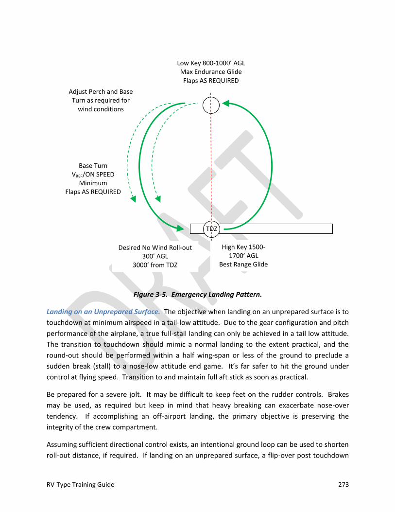
RV-Type Training Guide 273
Figure 3-5. Emergency Landing Pattern.
Landing on an Unprepared Surface. The objective when landing on an unprepared surface is to
touchdown at minimum airspeed in a tail-low attitude. Due to the gear configuration and pitch
performance of the airplane, a true full-stall landing can only be achieved in a tail low attitude.
The transition to touchdown should mimic a normal landing to the extent practical, and the
round-out should be performed within a half wing-span or less of the ground to preclude a
sudden break (stall) to a nose-low attitude end game. It’s far safer to hit the ground under
control at flying speed. Transition to and maintain full aft stick as soon as practical.
Be prepared for a severe jolt. It may be difficult to keep feet on the rudder controls. Brakes
may be used, as required but keep in mind that heavy breaking can exacerbate nose-over
tendency. If accomplishing an off-airport landing, the primary objective is preserving the
integrity of the crew compartment.
Assuming sufficient directional control exists, an intentional ground loop can be used to shorten
roll-out distance, if required. If landing on an unprepared surface, a flip-over post touchdown
High Key 1500-1700’ AGL
Best Range Glide Flaps UP
Low Key 800-1000’ AGL Max Endurance Glide Flaps AS REQUIRED
Base Turn VREF/ON SPEED
Minimum Flaps AS REQUIRED
TDZ
Desired No Wind Roll-out 300’ AGL
3000’ from TDZ
Adjust Perch and Base Turn as required for
wind conditions

RV-Type Training Guide 274
may occur. The cockpit roll bar/canopy bow is designed to protect the crew in the event this
occurs. Cockpit egress post-crash will depend on conditions and canopy condition. If the
aircraft comes to rest inverted and the canopy remains intact, a canopy breaker tool (if
equipped) may be used to assist with egress. If not equipped with a dedicated tool, it may be
necessary to improvise a canopy breaker (e.g., fire extinguisher, control stick, etc.) or kick to
break the canopy. If unstrapping with the aircraft inverted, be prepared for the subsequent fall
when the harness is released. Neck injury is highly probable if sufficient bracing cannot be
accomplished prior to releasing the harness.
If attempting a landing in a forested area, it may be possible to aim the fuselage between trees,
allowing the wings to absorb the brunt of the impact force (do not attempt to fly the airplane
between the trees if still airborne). If forced to land into a tree canopy, controlled tail-low flight
into the trees is safer than a stall at or above the top of the canopy.
AIRSPEED INDICATOR FAILURE
In the event of complete airspeed failure, GPS ground speed (when equipped) may be
referenced to assist with determining approximate airspeed, however the primary source of a
high AOA condition is the onset of buffet or other stall warning. If the aircraft is equipped with
an independent AOA system, that should be referenced. Known pitch and power settings
should be flown and allowance made for a slightly fast approach in the event of complete
airspeed failure. A suitable runway should be selected to allow for extended float during the
round-out prior to touchdown.
Other than instrument failure or malfunction, the most likely cause of an indicated airspeed
malfunction is a blocked pitot tube. If a proper airspeed check is conducted during the initial
takeoff run, the likelihood of suffering a blocked pitot tube in non-icing conditions is remote.
See PITOT STATIC MALFUNCTION.
DITCHING
1. Harness—SECURE
2. Flaps—UP
Note
A well-executed water landing generally involves less deceleration violence than a poor tree landing or a touchdown on rough terrain.
RV-Type Training Guide 275
A flaps up configuration is recommended for ditching to preclude a nose drop in the event of an
unintentional stall immediately prior to touchdown. A flaps-up stall will produce better
aerodynamic warning and less severe pitching moment than a flaps down stall.
3. Glide—L/DMAX (VREF/ON SPEED)
4. Approach
High Wind/Heavy Sea: INTO WIND
Low Wind/Heavy Swell: PARALLEL TO SWELL
5. Canopy—OPEN or JETTISON (When practical) PRIOR TO TOUCHDOWN
Opening or jettisoning the canopy prior to touchdown is recommended, since structural
damage during the water landing could make opening the canopy difficult or impossible after
landing.
6. Touchdown—TAIL LOW VS1 + 5
a. Maintain sufficient airspeed through a tail-first landing in the water. If the
airplane is allowed to stall with the flaps extended, it may pitch down nose first
into the water.
7. Harness—RELEASE
The crew must egress as rapidly as possible as the aircraft will likely sink quickly after
touchdown. If the aircraft does not sink immediately, the crew should assume that it may sink
rapidly at any time without warning.
RV-Type Training Guide 276
ALL WEATHER OPERATION
COLD WEATHER OPERATIONS
Information in this section conforms to Lycoming Service Instructions 1505 and 1148C (current Lycoming Service Information should be consulted). It is generally applicable to RV-types equipped with a Lycoming engine. If specific engine manufacturer’s or builder’s guidance is available for cold weather operations, it should be followed and supersedes information in this guide. The end of the oil breather should be checked for ice during pre-flight inspection. If this
becomes blocked, it will cause a loss of engine oil. It is critical to ensure that the engine has
been properly serviced with the correct grade of oil commensurate with ambient temperature.
As air cools, density is increased and more fuel is required for proper starting. More priming
may be required at cooler temperatures. In general, the engine should be pre-heated, if
required, started at idle power and allowed to warm up slowly. Plan a sufficient amount of
ground operation time before takeoff to allow for engine warm-up prior to starting the takeoff
run. A Lycoming engine is sufficiently warm for takeoff when the power can be advanced
without engine hesitation. If the engine is equipped with a carburetor, the accelerator pump
will add fuel at the carburetor to assist with starting. Caution should be exercised when using
an accelerator pump (i.e., pumping the throttle) to assist with starting, as this can lead to an
induction fire if misapplied, as can over-priming airplanes equipped with priming systems.
In extremely low temperatures, oil congeals, battery capacity is lowered, and the starter can be
over-worked. Improper cold weather starting can result in abnormal engine wear, reduced
performance and decreased time between overhauls, or failure for the engine to operate
properly. The use of pre-heat will facilitate starting during cold weather, and is required
when the engine has been allowed to drop to temperatures below +10°F/-12°C. Be sure that
the engine oil is in compliance with the recommended grades. Some aircraft may be equipped
with instrumentation that allows the pilot to determine engine block temperature prior to
start; this can be helpful determining whether or not it is desirable or necessary to pre-heat the
engine. Additionally, some aircraft are equipped with an engine pre-heating system.
In cool or cold weather, extra care should be taken prior to attempting takeoff with a cold
engine and cold oil. To prevent possible power loss, a proper warm-up should be conducted.
After initial start and warm-up at idle, maintain a minimum of 1000-1200 RPM during ground
operations to the maximum extent practical (to avoid spark plug fouling and assist with warning
the engine and lubricating oil). Oil pressure may be as high immediately following start, but
should fall into the normal range as the engine reaches normal operating temperatures. If in
doubt about power output, a brief, smooth full-throttle check is recommended. If the engine
RV-Type Training Guide 277
power can be advanced without roughness or hesitation noted, the engine is warm enough for
takeoff.
Exercise care when doing a high-power run-up on the ground. The RV-types are capable of
achieving flying speed with power settings as low as 1700-1800 RPM (typical run-up RPM).
Taxiway or runway conditions could be degraded in cold temperatures if ice and snow are
present, resulting unintentional sliding when power is advanced. If in doubt, it’s best to simply
spend the time on the ground allowing the engine to warm up.
High-volume Heater Use
1. Apply hot air directly to the oil sump, external oil lines, cylinders, air intake, oil cooler and oil filter in 5-10 minute intervals. Between intervals, feel the engine to be sure that
Caution
The use of a heated dipstick is not recommended by Lycoming because heat is not distributed throughout the engine, and concentrated heat may damage non-metal engine parts. Proper pre-heat requires a thorough decongealing of all oil.
If an engine is started cold without pre-heat, the high viscosity of the oil unseats the bypass valves and unfiltered oil flows through the engine.
Caution
Direct hot air carefully to avoid heat damage to non-metal parts. If operating in extreme cold weather, a blanket should be placed over the top of the cowl to aid in heat retention.
Caution
The engine may not be warm enough for takeoff if there are indications of engine roughness; low, high or surging RPM; high, low or fluctuating oil pressure; high or low fuel flow; and/or excessive manifold pressure.
Airplanes equipped with oil-actuated controllable pitch propellers will require a sufficient supply of suitably warm oil to ensure proper propeller operation.

RV-Type Training Guide 278
it is retaining warmth. Also check to be sure that there is no damaging heat build-up. During the last 5 minutes, direct heat to the top of the engine.
2. Immediately after pre-heating, start the engine according to the normal starting
process. Avoid cranking for more than 5 seconds each start attempt. 3. Avoid rapid acceleration after a cold start. Do not exceed idle RPM, recommended in
the engine Operator’s Manual, until oil pressure is stabilized above the minimum idling range. Depending on instrumentation, oil pressure may require up to one minute to stabilize. If some oil pressure is not indicated within 30 seconds of start, shut down the engine and determine the cause. If no leaks or damage is found, repeat the pre-heat before restarting.
4. Allow the engine to warm up at idle speed until oil pressure and temperature are
stabilized within normal limits and proceed to normal ground operations. 5. After completing the ground check, and before attempting takeoff, check oil pressure,
oil temperature, and cylinder head temperature to be sure that all are well within their normal operating ranges.
6. Insure that when takeoff power is applied smoothly, oil pressure, fuel flow, manifold
pressure, and RPM are steady. Surges or fluctuations may indicate that the engine is not warm enough for takeoff.
Carbon Monoxide Considerations
If the RV-type operated is equipped with a cabin heat system consisting of a muff around an
exhaust pipe (or pipes), any exhaust leak could induce dangerous amounts of carbon monoxide
(a combustion by product) into the cabin environment. Exhaust and cabin heat systems should
be inspected regularly for signs of exhaust gas leakage.
Carbon monoxide is colorless and odorless. It cannot be detected except by mechanical
means. Care should be exercised when using the cabin heat system to be alert for symptoms of
carbon monoxide poisoning. Symptoms of CO poisoning often include drowsiness and, perhaps
dizziness or reduced visual acuity. If the airplane is equipped with a CO detector, any warning
or evidence of excessive amounts of CO should be treated as real. In this case, the airplane
Note
Rapid battery discharge during cranking should be anticipated when the battery is cold (ambient temperature < 20oF).
RV-Type Training Guide 279
should be ventilated and landed as soon as practical (See EMERGENCY PROCEDURES, COCKPIT
VENTALATION/HEAT MALFUNCTION).
Induction System Icing
In flight, formation of induction ice will cause a loss of engine power. This loss of power may be
detected as a reduction of RPM (fixed pitch propeller), manifold pressure, or reduction in
EGT/CHT if the airplane is equipped with advanced engine instrumentation. In some cases, a
loss of airspeed or altitude may be the first sign that power has been compromised—especially
for aircraft with minimal instrumentation. This loss of power may sometimes be accompanied
by vibration or engine roughness. It may also be quite insidious. To detect power loss in flight,
a good technique is to note manifold pressure and/or RPM at level-off after the throttle and
mixture have been adjusted for cruise. If the airplane is properly trimmed, any reduction in
power will be evident by loss of airspeed/altitude and the pilot may note a “heavy” stick. If a
controllable pitch propeller or auto-pilot is fitted, use may initially mask symptoms of induction
system icing. Pilots must be alert for signs of icing when meteorological conditions are
conductive to icing formation.
Carburetor Icing
Ice can form in the venturi of the carburetor throat with any outside air temperature from -7oC
(20oF) to +38oC (100oF). It is most likely in the -1 to +15oC (30-60oF) range. The higher the
relative humidity, the higher the probability of carburetor ice forming (e.g., temperature dew
point spread 3oC or less). It may form with relative humidity as low as 50-60%. Visible moisture
need not be present, but on damp, cloudy, foggy or hazy days, be alert for power loss (e.g.,
visibility 1 SM or less, ceiling at or below 1500’ AGL or other visible moisture present).
Carburetor ice forms more readily when the engine is at low power settings. It may form
during ground operations and taxi. It is important to check engine power before takeoff and to
remove ice, if necessary.
Warning
Visible moisture and low temperatures are not required for the formation of carburetor ice. Warm temperatures and high humidity can be conducive to the formation of carburetor ice.
The Carburetor can be almost completely occluded with ice before signs of carburetor icing are observed.
RV-Type Training Guide 280
Carburetor Heat
Not all RV-types equipped with carbureted induction systems are equipped with carburetor
heat. A typical carburetor heat installation is a muff around an exhaust pipe (or pipes) that
provides heated air to the carburetor. This is best applied as an anti-icing system, i.e., it is
designed to preclude ice formation by maintaining carburetor throat temperature above
freezing. It may melt ice that has formed if accumulation isn’t too great, but its primary
purpose is to prevent ice formation. Generally, the carburetor heat will be plumbed inside the
air filter, i.e., providing a bypass source of induction air in the event the filter becomes clogged;
but individual installations will vary. Some airplanes are equipped with carburetor temperature
indicators, assisting with proper application of carburetor heat. If equipped, carburetor heat
should be checked for proper operation during the engine run-up.
Any time power loss is suspected in flight, carburetor heat should be selected immediately.
This may cause a further 10-15% power reduction and some engine roughness. The additional
power loss is caused by heated air injected into the induction system. This richens the mixture
and melts the ice, which then goes through the engine as water. The throttle may be advanced
and the mixture may be leaned to help get some of the lost power back, but immediately after
the application of carburetor heat, the pilot must be patient and keep the airplane flying until
the ice as completely melted and normal power returns. How long this will take depends on
the severity of the icing, but the pilot should expect a delay of 30 seconds to several minutes.
Do not deselect carburetor heat if ice is suspected.
In conditions where carburetor ice is likely to form, the pilot may use heat during cruise to
prevent the formation of ice in the carburetor. It is also appropriate to use full carburetor heat,
if needed, to prevent icing when operating at low power settings for descent, instrument
approaches or in the traffic pattern. If carburetor ice is suspected, full carburetor heat should
be applied immediately. If ice is present, the use of partial carburetor heat or leaving
carburetor heat on for an insufficient period of time may aggravate build up. If installed, the
carburetor temperature gauge is useful in determining when to apply carburetor heat.
Whenever the throttle is closed during flight, the engine cools rapidly and vaporization of fuel is
less complete than if the engine is warm. If carburetor icing conditions are suspected and
Caution
If carburetor heat is selected during approach and a go-around becomes necessary, it should be deselected prior to advancing power. Failure to do so could result in a loss of power during a critical phase of flight.
RV-Type Training Guide 281
closed-throttle operation is anticipated, turn carburetor heat on prior to closing the throttle
and leave it on during closed throttle operation. Carburetor heat will aid in fuel vaporization
and help prevent ice formation in the carburetor throat. It may be beneficial to periodically
open the throttle smoothly for a few seconds to keep the engine warm and provide sufficient
heat to help prevent icing.
Unless the engine manufacturer or builder recommends otherwise, do not use carburetor heat
during takeoff or climb. It is not necessary at high power settings for a typical Lycoming
installation and may cause detonation to occur. At ambient temperatures of -10oC (14oF) or
below, carburetor heat is not required since any moisture in the air is frozen.
Alternate Air Source
If the RV-type operated is equipped with fuel injection, an alternate air source should be
available for the induction system. Alternate air system plumbing will vary, but an alternate air
system should bypass the primary source in the event it becomes obstructed. Selection of
alternate air may be manual or automatic, depending on installation.
Fuel injected airplanes are, generally, less susceptible to induction icing than airplanes
equipped with carburetors; however impact (airframe) icing is still a possibility. Any time
unexplained power loss is encountered or icing is suspected, alternate air should be selected (if
the system is not automatic).
Pitot Heat
If equipped, pitot heat should be selected on when OAT is 6o C (43oF) or less.
Mixture Adjustment
Cold ambient temperature/OAT results in a leaner mixture for a given mixture lever setting.
Lean in accordance with engine manufacturer’s or builder’s recommendations (See NORMAL
PROCEDURES).
Airframe Icing
Pre-flight Considerations
Planning. Flights should be planned to avoid known or suspected/forecasted icing conditions.
Conditions can change rapidly. Generally, structural icing is an IMC phenomenon. It is normally
encountered in clouds any time the temperature drops below freezing and super-cooled water
is present. If flight in clouds or visible moisture is avoided or minimized, the risk of icing
diminishes.
RV-Type Training Guide 282
Pre-flight Inspection/Aircraft Preparation for Flight. Prior to flight, make sure that all frost and
snow are removed from the aircraft. Even a small amount of frost or snow adhering to flying
surfaces may decrease lift by up to 33%, and at times may even prevent the aircraft from
becoming airborne. At ambient temperatures at or below +5oC (40oF), all flying surfaces and
the propeller should be thoroughly checked for evidence of frost or ice prior to flight.
In-flight Considerations
Flight in icing conditions should be avoided. Icing should be considered if OAT is below 6oC,
visible moisture is present, and/or temperature and dew point are within 3oC of each other,
ceiling is at or below 1500 feet and/or visibility is less than 1 SM. If icing is encountered, keep
in mind that structural icing is a condition that can only get worse. Therefore, during an
inadvertent icing encounter, it is important the pilot act to prevent additional ice accumulation.
The first course of action should be to leave the area of visible moisture and immediately return
to an area where there wasn’t any ice. This might mean descending to an altitude below the
cloud bases, climbing to an altitude that is above the cloud tops, or turning to a different
course. If this is not practical, then the pilot must move to an altitude where the temperature is
above freezing. If icing conditions are encountered, the pilot should consider making
occasional, controlled pitch inputs to ensure that ice build-up between the end of the
horizontal stabilizer and the elevator counterweight does not occur.
Tailplane Icing. If icing is unintentionally encountered, the pilot should visually check the
leading edge of the horizontal stabilizer for ice accumulation (as practical). Even short
encounters and small buildups of ice on aircraft can drastically affect the performance and
handling qualities of the airplane. The horizontal stabilizer, which has a smaller leading edge
radius than the wing, will accumulate ice at a faster rate than the wing. It is estimated that ice
accumulates 3-4 times faster on the stabilizer than the wing. Sufficient ice accumulation on the
horizontal stabilizer and elevator surfaces may result in a tail stall. Generally, a tail stall will
occur immediately after extending the flaps, or, once the flaps are extended, after airspeed
changes, power increase or nose-down pitch commands. The downward force applied by the
horizontal tail increases when the flaps are deployed, airspeed is increased (with the flaps
down), power is increased (with the flaps down) and the pilot commands pitch down with
Warning
Icing may be encountered in any season, at any geographic location at any altitude up to 18,000 feet (and sometimes higher).
RV-Type Training Guide 283
forward application of the control stick. Symptoms of tail icing include: elevator pulsing,
oscillations, or vibrations; abnormal nose-down trim change; reduction in loss of elevator
effectiveness; sudden change in elevator force; sudden uncommanded nose-down pitch; or any
unusual or abnormal pitch anomalies. If any of these symptoms occur, the pilot should
immediately retract the flaps, increase airspeed appropriately and slowly apply sufficient power
for aircraft configuration and conditions. Nose-down pitch changes should be made slowly.
If icing conditions are encountered, primary attention should be focused on aircraft control.
The airplane should be flown manually (if auto pilot equipped). It may not be practical or
possible to maintain altitude. Turn cabin and carburetor heat on or select alternate air
source, as appropriate. Monitor carburetor temperature, if appropriate and equipped.
Monitor OAT, if equipped. Communicate the state of your situation to air traffic control and
clearly state the urgency of the situation. Do not delay taking action to fly out of icing
conditions. When requesting altitude changes, advise ATC that you will accept a heading or
course change to expedite the altitude change. Do not accept delay in coordinating with ATC,
declare an emergency, as required to expedite handling and take the appropriate action
required to mitigate icing effects.
Icing Considerations
1. All icing encounters are potentially fatal. The type, amount and rate of icing
accumulation aren’t predictable.
2. If ice is encountered, immediately return to where there wasn’t any. Regardless of the
course of action selected, immediate action is required if icing is encountered. Turn,
climb (if tops are known) or descend below cloud bases and attempt to leave visible
moisture. If nothing else, move to an area where the temperature is above freezing.
Consider diverting or returning to the departure airport if conditions are worse than
forecast. Declare an emergency if the safe outcome of flight is in doubt. Do not delay
taking action.
Warning
Be alert for signs of ice formation when operating in IMC with the auto pilot engaged (if equipped). A properly functioning autopilot may handle initial accumulation and may mask any handling cues associated with ice formation, possibly to the point where control is compromised when the auto-pilot disconnects or is disconnected.
RV-Type Training Guide 284
3. Disengage the autopilot (if equipped) and do not use flaps. Avoid/delay power
reduction to the maximum extent practical.
4. Use carburetor heat or alternate air source (as appropriate). If equipped, use
carburetor heat frequently. Signs of carb icing (e.g. power loss) may not occur until
substantial ice has already built up in the carburetor throat. Induction icing is most
likely at low power settings. Carburetor heat is most effective when applied before
reducing power.
5. Never takeoff with snow or frost on the aircraft. Even barely visible accumulations can
significantly degrade performance. RV-types should be inspected visually and by touch
to determine if frost is present on a flying surface.
6. Any forecast or PIREP should be considered appropriately. Neither one is a guarantee
that icing isn’t present or won’t be encountered. Icing can be an extremely localized
phenomenon. Any information other than what you observe real-time should be
considered advisory only.
Caution
If the airplane is not fitted with a heated pitot and/or pitot heat is not turned on, the first sign of icing may be a loss of pitot pressure. In this case, the airspeed indicator will become unreliable. If equipped, advanced instrumentation systems may provide annunciation of a loss of pitot pressure (See EMERGENCY PROCEDURES, PITOT STATIC MALFUNCTION and AIRSPEED INDICATOR FAILURE).
Depending on fuel vent configuration, it is possible for ice to accumulate on the fuel vents. If a fuel vent ices over, the fuel tank may begin to collapse before the flow of fuel to the engine stops. A collapsed fuel tank can be detected by visually monitoring the condition of the fuel tanks. In RV-types, the fuel vent systems are separate. If deformation is observed for fuel flow interrupted, the other tank should be selected.
Pitot, fuel vent and/or oil breather icing may occur without other visual indications of ice build-up.
RV-Type Training Guide 285
Cold Weather Altimeter Error
The pressure altimeter indicates true altitude MSL when operating at standard pressure and
temperature (International Standard Atmosphere [ISA]). Non-standard pressure conditions are
corrected by applying the correct local area altimeter setting. Temperature differences from
ISA (15oC or 59oF) result in true altitude being lower than indicated altitude whenever the
temperature is colder than ISA. True altitude variance under conditions of colder than ISA
temperature could pose the risk of inadequate obstacle clearance. ATC-assigned altitudes
should not be corrected, but correction may be applied to charted IFR approach altitudes (e.g.,
procedure turn, FAF crossing, etc.). ATC must be advised if applying correction.
Table 3-3 shows how much error can exist when the temperature is extremely cold. To use the
table, find the reported temperature in the left column, and then read across the top row to
the height above the airport/reporting station (e.g., subtract the airport elevation from the
altitude of the FAF). The intersection of the column and row is the amount of possible error.
Note that the altitude error is proportional to both the height above the reporting station
elevation and the temperature at the report station. For instrument approaches, the reporting
station elevation is assumed to be airport elevation.
Example #1: The reported temperature is -10oC and the FAF is 500 feet above the airport
elevation. The reported current altimeter setting may place the aircraft as much as 50 feet
below the altitude indicated by the altimeter.
Note
If temperatures are well below standard, induced altimeter error may be significant.
Warning
If there is visible ice accumulation on the airplane, a no-flap approach and landing should be flown.
A controllability check should not be performed with ice on the airframe. The airplane should be decelerated slowly and any buffet or uncommanded pitch cues should be respected—do not attempt further deceleration. Higher than normal speeds for approach and landing should be expected.

RV-Type Training Guide 286
Example #2: The reported temperature is -20oC and the airplane is on downwind at 1000 feet.
True altitude is 140 feet below indicated altitude. Notice that the amount of indicated error
will decrease throughout the final segment.
Table 3-3. ICAO Cold Temperature Error Table
Rep
ort
ed
Tem
per
atu
re C
o
Height Above Airport in Feet
20
0
30
0
40
0
50
0
60
0
70
0
80
0
90
0
10
00
15
00
20
00
30
00
40
00
50
00
+10 10 10 10 10 20 20 25 20 20 30 40 60 80 90
0 20 20 30 30 40 40 50 50 60 90 120 170 230 280
-10 20 30 40 50 60 70 80 90 100 150 200 290 390 490
-20 30 50 60 70 90 100 120 130 140 210 280 420 570 710
-30 40 60 80 100 120 130 150 170 190 280 380 570 760 950
-40 50 80 100 120 150 170 190 220 240 360 480 720 970 1210
-50 60 90 120 150 180 210 240 270 300 450 590 890 1190 1500
Notes
Correction is based on the reported temperature at the station, not OAT.
Correction assumes the RV-type operated has had the altimeter properly calibrated and tested.
Note
In some cases, minimum temperature for the conduct of baro-based GPS approaches is specified and should be observed.

RV-Type Training Guide 287
RAIN AND SNOW
Propeller Erosion
Depending on propeller type, erosion of the leading edge can occur when encountering rain,
snow or ice pellets in flight. Metal blades are generally impervious to moisture effects, but
wooden and composite blades without leading edge protection may erode. If the airplane is
equipped with a wooden or composite propeller without leading edge protection and heavy
precipitation is encountered, consideration should be given to reducing power to 2200 RPM (if
practical) to minimize the chance of propeller damage.
Hydroplaning
Hydroplaning can occur if landing in standing water whose depth exceeds the depth of the
tread on the tires. When brakes are applied, there is a possibility that a brake will lock and the
tire will ride on the surface of the water. When the tires are hydroplaning, directional control
and braking action is virtually impossible. Hydroplaning speed can be estimated by multiplying
the square root of the tire pressure by 9. Based on nominal RV-type tire pressure, dynamic
hydroplaning is likely to occur at speeds of 45-50 MPH/ 40-45 Knots. If landing on a wet hard-
surfaced runway, a firm touchdown should be flown at normal speed and flaps retracted as
soon as practical. If hydroplaning is encountered, brakes should be released; aerodynamic
control maintained and then brakes should be re-applied.
Contaminated Runway Effect on Takeoff and Landing Performance
Runway surface type, condition and ambient conditions affect takeoff and landing
performance; in some cases significantly. Generally, specific takeoff and landing data derived
from flight test is not available for most RV-types. Table 3-4 contains safety factors that may be
applied to estimate takeoff and landing performance with a contaminated runway.
Precise airspeed control is more critical when operating from a contaminated runway.
Although basic RV-type takeoff and landing performance is excellent, a contaminated runway
can significantly impact takeoff and, particularly, landing performance; especially if multiple
factors must be considered, e.g., contaminated runway with a tailwind, etc. A stabilized final
approach should be flown at VREF/ON SPEED. Final approach and touchdown techniques
appropriate for a short field/maximum performance landing may be appropriate when landing
on a contaminated runway (See NORMAL PROCEDURES, SHORT-FIELD APPROACH and
LANDING).
Be alert for signs of hydroplaning (See HYDROPLANING) during deceleration at approximately
50 MPH / 45 Knots if the runway is wet. Utilize aerodynamic control and minimize cross-wind

RV-Type Training Guide 288
to the maximum extent practical (the ability to handle cross-wind, particularly in the later
portion of the landing roll during deceleration can be greatly reduced on a contaminated
runway.
Table 3-4. Contaminated Runway Effect on Takeoff and Landing Performance
Condition Takeoff
% Increase in Distance to 50’ AGL
Landing % Increase in Distance from
50’ AGL
Wet Paved Surface Minimal Effect +15%
Wet Grass (up to 8” on firm soil)
+30%
+35% Note: very short grass may be
slippery, landing ground roll distance may increase by up
to 60%
Soft ground, mud or snow ≥ +25% ≥ +25%
Ice Minimal Effect ≥ 100%
BASIC IMC CONSIDERATIONS
The outstanding handling characteristics and limited stability margins of RV-types can result
in high pilot work load when operating under instrument meteorological conditions (if
equipped). This should be anticipated and proper attention devoted to maintaining aircraft
control at all times. If equipped, an autopilot and/or advanced avionics can reduce pilot
workload during IMC operations (if the pilot is familiar and proficient with the operation of
those systems).
Single-pilot IMC operations in RV-types require skill and concentration; and are likely to impose
high workloads and associated mental stress. To facilitate IMC operations (if appropriate)
proper flight preparation/planning, organization, cockpit resource management, and
prioritization (avoiding distraction) will assist with maintaining situational awareness
throughout all phases of flight. It is important to have planned (and updated) contingency
options if circumstances change during flight. Charts and other publications (or Electronic Flight
Bags) should be organized so that all information is readily available in the anticipated order
that it will be required during flight. If carrying a passenger, consider politely adopting a “sterile
cockpit” during periods of high workload (usually all phases of flight except cruise). To assist
with maintaining situational awareness, know exact position at all times (greatly facilitated by
GPS and moving map displays, if equipped) and think ahead to the next event that will take
place. Maintain awareness of changing weather conditions by monitoring enroute, destination
and alternate weather. Monitor fuel consumption and balance. If not equipped with an

RV-Type Training Guide 289
autopilot, maintaining fuel balance between wing tanks within approximately 6-8 gallons will
assist with maintaining heading control.
ROUGH AIR OPERATION / TURBULENCE PENETRATION
Due to the light wing loading and speed capability of RV-types, turbulence can produce an
unpleasant, rough ride, depending on atmospheric conditions. At normal cruise speeds,
encounters with turbulence can often result in being thrown about the cockpit or contact of the
pilot’s head with the canopy. Yaw excursions about the vertical axis are typical. If turbulence
or rough air is encountered, harnesses should be tightened as snuggly as possible and
consideration should be given to slowing down. Turbulence penetration speed (VB) is not
specified for RV-type aircraft. VB may be approximated by multiplying stall speed (CAS) by 1.7
or subtracting 5-10 MPH/knots from appropriate maneuvering speed. If moderate or greater
turbulence is encountered, the pilot should slow to maneuvering speed (VA) or less and
maintain attitude. Altitude and heading excursions are likely and if operating under an ATC
clearance, it may be necessary to obtain an altitude block or deviate from cleared altitude.
Turbulence can degrade handling characteristics when the airplane is loaded at aft CG
conditions. If operating with an autopilot engaged, be alert for disconnect to occur in rough air.
If operating without an autopilot, anticipate high control workload and prioritize accordingly.
CRUISE DESCENT
A three degree instrument descent can be flown by setting 15-17” MAP (approximately 1800-
2000 RPM) and adjusting pitch -3o from cruise. Airspeed should be approximately VN0. If
descending from high altitude, do not exceed VNE TAS. When computing top of descent, allow 1
NM to decelerate from VN0 to holding speed or 2 NM to decelerate to VAPP in addition to
distance required for standard 300’ per nautical mile descent. VVI will be equal to 5 x
groundspeed (when available) for a 3o descent path. Turn radius will be approximately 1%
groundspeed in NM (when available). Be alert for induction icing during descent if visible
moisture is present or conditions are favorable for the formation of ice.
HOLDING
Maximum holding duration can be obtained by flying at L/DMAX (ON SPEED). L/DMAX occurs at
maximum endurance glide speed (approximately VX [if known] or 1.4 VS1) . However, due to the
relatively flat drag curve of RV-types, recommended holding speed is 120 MPH / 105 Knots.
This speed will provide better energy maneuverability for a very moderate increase in fuel flow
and is approximately equal to Carson’s Number for the RV-4/6/7/8. 40-45% power
(approximately 16-17 Inches of manifold pressure at 1900-2000 RPM) and +2.5o of pitch will
establish a 120 MPH /105 Knot holding condition. Fuel flow for a typical Lycoming installation
RV-Type Training Guide 290
will be approximately .1 gallons per minute at holding speed power setting (e.g., 25 minutes of
holding requires 2.5 gallons of fuel). Be alert for induction icing if visible moisture is present or
conditions are favorable for the formation of ice during holding.
APPROACH
RV-types are Category A for instrument approaches. Use 90 MPH (80 knots) and 11-12 inches
of manifold pressure, RPM as required with the carburetor heat ON (for airplanes equipped
with a carbureted induction system and equipped with carburetor heat) for instrument
approach. Vertical velocity (VVI) should be set 400-500 FPM (displayed groundspeed [when
equipped] X 5) for a 3o glide path. For non-precision approaches, use 10 inches of manifold
pressure and an 800-1000 FPM descent rate for stair-step approaches, if desired. In general,
approach descent rates greater than 1000 FPM should be avoided. If equipped with advanced
instrumentation, a constant descent approach (CDA) is desirable to a stair-step. It may be
flown by reference to published descent angle or calculated VVI.
A visual descent point (VDP) should be computed (if not published) by dividing published height
above touchdown (HAT) by 300 and adding that distance to the end of the runway. Use of a
VDP will assist with maintaining a stabilized 3o final approach to landing. A properly flown CDA
will ensure the airplane is coincident with VDP approaching minimums.
LOW-LEVEL WIND SHEAR
Wind shear is a sudden, drastic change in wind speed and/or direction. Speed changes of up to
50 knots and 180o change in direction can be associated with low-level wind shear. For RV-
types, severe wind shear may be defined as a change in velocity (either IAS or reported wind
speed) of 15 MPH / Knots or more and vertical velocity changes greater than 500 FPM. If
equipped with advanced instrumentation, trend displays may provide the first warning of a
wind shear encounter (i.e., rapidly increasing/decreasing airspeed or VVI). Other cockpit cues
include pitch changes greater than 5o, ± 1 dot deviation on an ILS or LPV approach, and/or an
unusually high or low power setting to maintain normal approach speed.
Table X-X: Causes of Wind Shear Mishaps
Convective Weather (Thunderstorms, Rain and/or Snow Showers) 65%
Frontal Systems 15%
Low Altitude Jet Streams 5%
Strong or Gusty Surface Winds 5%
All other causes (Temperature Inversions, Mountain Waves, Sea Breeze Circulation and Unknown Causes)
10%

RV-Type Training Guide 291
The single best technique for dealing with low-level wind shear is avoidance. Do not attempt
takeoff if wind shear is suspected or reported in the local vicinity. Most general aviation wind
shear mishaps occur during landing phase, with 50% of these mishaps occurring on the airport.
Most non-convective wind shear encountered during VFR operations is associated with frontal
activity. Systems with closely spaced isobars are likely to produce strong and gusty winds.
Buildings, trees or other obstacles along the runway can cause wind currents to become even
more erratic over the runway itself. Microbursts associated with convective activity produce
the most dangerous wind shear.
If wind shear is suspected or encountered, an immediate go-around type escape maneuver
should be performed. Select wide open throttle in a controlled manner (do not jam the throttle
at low airspeed). Establish a normal climb attitude (8-10o nose up), even if descending. If flaps
are up or extended 20o or less, do not change flap configuration during a wind shear encounter.
Retract flaps (if fully extended) from 40o to 20o. Maintain positive control and avoid ground
contact. It may be necessary to increase angle of attack to just below stall if the wind is
shearing from a headwind to a tailwind (i.e., performance decreasing shear). Minimize bank
inputs to maximize climb gradient capability. Do not stall in an attempt to avoid the ground.
RV-types have good power-to-weight ratio and respond relatively quickly to power and control
inputs, but wind shear is capable of exceeding aircraft performance.
RV-Type Training Guide 292
HANDLING CHARACTERISTICS
STATIC MARGIN
Aircraft flight characteristics represent a compromise between the control response required to
achieve desired performance and the stability necessary to keep pilot work load acceptable. As
stability increases, responsiveness to control inputs or other disturbances (e.g., turbulence)
decreases. As stability decreases, responsiveness to control inputs or other disturbances
increases. Longitudinal stability (pitch) has the most critical effect on aircraft performance. A
measure of longitudinal stability is static margin, which is the distance, expressed as a percent
of the mean aerodynamic chord between the aircraft CG and aerodynamic center (AC or
nominal point of lift). If the CG and AC are coincident, the static margin is zero and the aircraft
will exhibit neutral longitudinal stability. A neutrally stable aircraft will remain at any angle of
attack to which it is displaced by control movement or other disturbance. If the CG is forward
of the AC, the aircraft is longitudinally stable. It will tend to return to the trim angle of attack
following a control movement or other disturbance. Conversely, if the CG is aft of the AC, the
static margin is negative and the aircraft is longitudinally unstable. In this condition the aircraft
will continue to pitch in the direction toward which it is disturbed by control movement or
other disturbance. There are no sharp demarcation lines below which the aircraft becomes
suddenly uncontrollable or above which the pilot can completely disregard longitudinal stability
considerations. Beyond the aft CG limit, pilot reaction time may be too slow to counter a pitch
change.
Warning
Information in this section does not pertain to any one specific aircraft. The basic aircraft configuration (side-by-side vs. tandem), engine/propeller combination fitted, empty weight and actual aircraft load condition have a profound effect on thrust available and weight and balance and, subsequently, performance, stability and handling characteristics. Handling characteristics of RV-type aircraft will vary according to type, configuration and loading.
Information in this section is not intended as a substitute for proper flight training.

RV-Type Training Guide 293
STABILITY AND CONTROL
Longitudinal Stability: The tendency to remain at a constant trim speed, and to return to that
trim speed after being displaced by a pitch control input. RV-types exhibit positive longitudinal
stability when loaded within center of gravity limits as specified by the designer. Some RV-
types may exhibit negative stick-free longitudinal stability at low speed and high power. In this
case, the airplane will diverge from trimmed speed and may decelerate to the stall if the pilot
does not actively control pitch/speed.
Lateral (Roll) Stability: The tendency of the bank angle to remain constant or to return to
wings level. RV-types exhibit neutral lateral stability and tend to remain at the bank angle to
which it was displaced.
Directional (Yaw) Stability: The tendency of an airplane to maintain a directional heading
when wings are level (no roll), and to return to a steady heading after release of a yaw input
control (rudder). RV-types exhibit positive directional stability.
Proper aircraft response (i.e., stability) is confirmed by performing a weight and balance
calculation for existing conditions and conduct of a stability check. A stability check should be
flown prior to the conduct of maneuvering flight to confirm proper aircraft response.
CENTER OF GRAVITY CONSIDERATIONS
The aerodynamic center of RV-types is relatively fixed and the CG moves aft throughout flight
as overall gross weight decreases due to fuel burn. This results in a decrease in overall static
margin as the flight progresses. As the CG approaches the aft limit, the tendency to over-
control should be anticipated. The stick force gradient (pounds of pull per G) will decrease and
pilot induced oscillations are possible if the pilot over-shoots desired pitch and counters with
excess motion in the opposite direction. Maneuvers requiring precise control (including close
formation) are more difficult at aft CG conditions. However, adequate positive static margin
remains for control if CG limits are observed. If aerobatic maneuvering is conducted, the aft
Warning
Pitch stability is reduced at low airspeed as pitch is increased and some stick force lightening occurs in all RV-types, especially at high power settings. The aircraft may diverge from trimmed speed at high power and low airspeed at aft CG. The aircraft may decelerate to an unintentional stall with stick pressure relaxed. The pilot must actively monitor pitch/speed during climb in IMC conditions or at climbs at low altitude in any weather conditions.

RV-Type Training Guide 294
aerobatic CG limit (when appropriate), should never be exceeded. It should be assumed that
no static margin exists aft of the designer’s recommended CG limit(s).
RV-type CG shift in flight is caused by fuel burn. Various conditions should be considered and
several examples should be calculated for the RV-type operated for training to assess the
magnitude of the shift. The most important consideration is that the actual CG does not move
aft of designer’s limits during the conduct of a flight.
The effect of gross weight needs to be considered during pre-flight planning and when
operating the aircraft. During Phase 1 testing, RV-types should have demonstrated safe
performance when operating at maximum allowable gross weight. Some RV-types have
operating limitations specifying maximum allowable gross weight in excess of designer’s
recommendations.
Certified, production aircraft have the CG limits established which (if adhered to) will prevent
the airplane from exhibiting characteristics of neutral or negative stability. The same is true of
the RV-types, however because the testing of individual aircraft is, generally, not as advanced
and thorough as factory testing; and because each RV-type airplane has a different
manufacturer (builder), all RV-types do not exhibit uniform stability characteristics. For any
airplane flown at or near the aft CG limit, control responses approaching neutral should be
expected.
Advanced handling and confidence maneuvers, because of the associated unusual attitudes,
are more likely to result in an unintentional out-of-control situation developing than non-
maneuvering flight. Maneuvering performed with an aft CG condition can be hazardous both
because of the light pitch control forces which can lead to accidental stalls and spins, and
because recovery from those stalls and spins will be more difficult because of the aft CG
condition. Advanced handling should only be attempted in aircraft with appropriate testing
complete and log book annotations/placards/operating limitations issued allowing the conduct
of appropriate maneuvers. The aircraft should be loaded within designer’s limits for the
Warning
The CG of the RV-types moves aft throughout flight as fuel is burned. CG location should be computed for takeoff and anticipated landing conditions. Shift is proportional to initial CG/loading: for forward/light conditions, shift is generally less; for aft/heavy conditions, shift may be greater.
RV-Type Training Guide 295
conduct of maneuvering flight. The aerobatic aft CG limit is forward of the ultimate CG limit to
provide static margin and adequate autorotation recovery characteristics.
The airplane is designed to have positive longitudinal stability/adequate static margin when
loaded with the CG within designer’s recommended limits. It is in equilibrium at design cruise
speed. The nose down tendency caused by the CG being forward of the center of lift is
balanced by stabilizer down load resulting from the negative incidence angle (relative to the
wing angle) of the stabilizer. So, a constant static load is balanced by an aerodynamic force
which will vary with airspeed. If the aircraft’s nose is lowered, an increase in speed will result,
and that will cause a greater download on the stabilizer, which will in turn raise the nose again
to bring the speed back to where it started. The opposite will happen if the nose is raised.
However, the aircraft will normally overshoot its original trimmed attitude and speed. Thus
there are usually several cycles of pitch hunting required to return to stable flight. Each cycle
(direction of initial displacement and then movement in the opposite direction) is of decreasing
amplitude (altitude variation). These pitch cycles are called phugoids and the time required for
the airplane to complete a cycle is referred to as deadbeat response. This is depicted in
illustration 15-1 in Figure 3-5.
Figure 3-6, Illustration 15-2 depicts the airplane loaded to a more forward CG condition, for
which an elevator trim force is needed to maintain equilibrium. Generally, a nose heavy
airplane is more stable because of the greater difference between the static weight position
and the dynamic force of the trimmed elevator. This condition is also referred to as increased
static margin.
Figure 3-6 Illustration 15-3 shows the aircraft loaded so that the CG and center of lift are at the
same point. Thus, no stabilizing trim load would be required of the tail. But, if there is no trim
load, there is no restoring load, and thus no positive stability. In this condition, the aircraft
would have neutral stability. It would continue to fly at whatever attitude it is placed or
displaced to.
Figure 3-6, Illustration 14-4 shows the airplane loaded to an extreme where the CG is aft of the
center of lift and where the horizontal tail surfaces must produce a lift force to maintain level
flight. In this condition, when the nose is lowered, speed will increase and the stabilizer force
will increase. But since there is a lifting force or upload on the tail, it will continue to lower the
nose and produce more lift and more speed, etc. If the nose was raised and the speed
decreased to less than trim speed, the reverse would occur: airspeed would continue to drop
until a stall occurred, recover from which would be difficult and spin entry would be probable.
This is an unstable condition because the forces acting on the aircraft are destabilizing with a
change in speed. This condition is referred to as pitch divergent. It is extremely difficult to fly
an airplane that is pitch divergent and is dangerous.
RV-Type Training Guide 296
In summary, as the CG moves aft, the aircraft will go from having positive stability, to neutral
stability and then to negative or divergent stability. The deadbeat response time is inversely
proportional to static margin. As the CG moves aft and static margin decreases, deadbeat
response time increases and stick force decreases.
Longitudinal (Pitch) Stability. Overall longitudinal stability is satisfactory with the aircraft
loaded within prescribed limits. There is a positive linear stick force/G relationship that
provides sufficient protection against over-G if proper control technique is utilized. Overall
control harmony is good with higher static stability in cruise leading to relatively higher control
forces in pitch compared to the ailerons, which remain crisp throughout the flight envelope.
Harmony improves and overall handling characteristics become sprightlier as airspeed is
reduced, pitch is increased and/or loading moves the CG aft. Overall, side-by-side RV-types
exhibit a smaller CG range than tandem types, thus handling characteristics do not vary quite as
much with load change.
Static margin is reduced during full-power climbs at low CAS. Pitch stability becomes neutral
when maneuvering through 90 degrees of pitch or dive during aerobatic maneuvering.
Although RV-types exhibit an acceptable longitudinal stick force gradient throughout the
maneuvering range, it varies in overall magnitude with actual CG location, pitch angle and (to a
lesser extent) altitude. The best way to limit over-control is to smoothly control the pitch RATE
throughout maneuvering. Airspeed DOES NOT affect stick-force gradient, and any perceived
lightening is a result of pendulum effect induced by pitch change and actual CG loading, the
aerodynamic center remains relatively fixed at all angles of attack up to the stall. Due to the
light wing loading and stability of the design, turbulence can effect performance and the pilot
should be aware that increased vigilance is required if turbulence is present.
When flying in turbulence, the aft-loaded (less pitch stable) airplane will tend to pitch up or
down, and that pitching may intensify in magnitude unless corrected by the pilot. RV-type pitch
control forces are light, and any over-controlling will require an opposite pressure to correct. If
a pilot induced oscillation is encountered, it is best to relax stick pressure (or freeze the stick
momentarily with the velocity vector above the horizon if at low altitude) to damp inputs. RV-
types are prone to yaw excursions in turbulence.
Note
RV-types exhibit weaker pitch stability as airspeed decreases. As angle of attack increases, the effective distance between the center of lift and the CG decrease, reducing overall static margin.

RV-Type Training Guide 297
Figure 3-6. Basic aircraft stability.
Aerobatic Limits. Light pitch control forces, reduced pitch stability and asymmetric control
application lead to the possibility of over controlling and over-stressing the airframe. The
aerobatic aft CG limit is established to provide an increased static margin during maneuvering.
RV-Type Training Guide 298
Due to the gross weight and CG limitations of RV-types, the capability to perform aerobatics
with passengers aboard can be problematic.
Pitch Trim. All RV-type aircraft are equipped with pitch trim. The aircraft are fitted with a
servo-tab on the left elevator. Actuation may be mechanical or electric. The tab is highly
effective and trim response varies by the type of actuator fitted. Care should be exercised to
apply small, precise inputs to avoid over trimming, especially at high airspeeds for aircraft fitted
with a manual trim lever. A trim position indicator may or may not be fitted. If specific
builder’s guidance is not provided, takeoff should be performed with the trim tab set to neutral
(i.e., tab aligned with the trailing edge of the stabilizer). If no position indicator is fitted, it may
be practical to observe trim tab position on the ground by applying sufficient back stick and
looking at the trim tab position to set neutral trim prior to takeoff. In flight, it is also practical
to observe the position of the elevator counterweight (except on the RV-3 without balanced
elevators) relative to the leading edge of the horizontal stabilizer to ascertain trim setting.
Directional (Yaw) Stability. Strong directional stability and adequate dihedral effect provides a
good control harmony in roll and yaw. When yaw is introduced, the damping cycles are rather
short period. The airplane exhibits a linear aileron/rudder relationship for sideslip angles up to
full rudder deflection with and without flap. Sideslip can be used comfortably on the final
approach, with significant effect on approach angle and no pitot/static interference. Excellent
rudder authority exists throughout the flight envelope for all RV-types.
Due to the excellent speed ratio of RV-types (i.e., large range between Vmax and stall speed), it is
not possible to have a single rudder trim setting that will keep the ball centered during all flight
conditions. A compromise “feet on the floor” cruise trim setting is, generally, provided by
adjustment of the fixed tab on the trailing edge of the rudder. Some aircraft may be equipped
with adjustable rudder trim, either manual or electric. For airplanes equipped with a fixed tab,
maneuvering flight or speeds other than cruise will require rudder input for coordinated flight.
In general (assuming the airplane was built with no vertical stabilizer offset), right rudder input
will be required during low airspeed, high power conditions and left rudder will be required
Note
Due to limited dihedral effect and excellent directional stability, it is not practical to control the position of the lift vector with rudder input alone. Regardless of AOA, the primary means for rolling the airplane is aileron input coordinated with sufficient rudder to counter any adverse yaw created.
RV-Type Training Guide 299
during most situations other than cruise and low airspeed, high power. A mechanical or
electronic inclinometer (ball) should be referenced to coordinate flight: “step on the ball” as
required to center it.
Lateral (Roll) Stability. The airplane exhibits neutral lateral stability. If rolled, it will tend to
remain in that bank angle until the pilot applies additional input. The airplane is equipped with
balanced Friese-type ailerons that are effective throughout the speed range of the airplane.
These ailerons are designed so that the lower edge protrudes below the wing with the aileron is
deflected up, thus countering adverse yaw to a degree and somewhat mitigating the need for
coordinating rudder in a turn. For a properly constructed and rigged aircraft, the primary cause
of any perceived lateral instability or “heavy wing” is a variance in fuel level, with a tendency to
roll toward the wing with more fuel in the tank. RV-types may or may not be fitted with roll
trim. In general, consider keeping fuel load balanced throughout flight.
STALLS
RV-3/4/6/7/8 types utilize a NACA 23013.5 airfoil section that stalls at 14-15o angle of attack.
The RV-9 utilizes a proprietary airfoil that stalls at XXo angle of attack. RV-types exhibit
conventional stall characteristics power off or power on. Generally, however, there is little
advance stall warning in the form of pre-stall buffet. Buffet which does occur does so within a
MPH/Knot or two of a fully developed stall. For typical 1 G level stalls, the airplane will exhibit a
nose up attitude prior to stalling, which can be fairly pronounced for power-on stalls due to the
high power loadings of RV-types. The following discussion assumes a “clean wing”
configuration, i.e., no stall strips or vortex generators fitted. Stall strips and vortex generators
may change aerodynamic warning and/or stall characteristics, if fitted.
1-G Stalls. An important concept to understand is that for a given gross weight, indicated stall
is what it is. In other words, the airplane will stall at that indicated speed, regardless of how
accurate the indication is (i.e., how well the system is calibrated). Indicated stall speed is
affected by flap position: if flaps are extended, indicated stall speed will decrease. The airplane
will always stall at critical angle-of-attack, which does not change regardless of load factor,
gross weight or aircraft configuration. If the airplane is equipped with a properly calibrated
AOA system, that system should serve as the primary instrument reference for determining
when critical angle of attack is being approached. Some aircraft may be fitted with a stall
warning device, that if properly calibrated may also provide stall warning. If the RV-type
operated for training is only equipped with an airspeed indicator (mechanical or electronic), it
may be necessary to establish an indicated stall speed commensurate with existing gross
weight conditions, as required for reference.
RV-Type Training Guide 300
One technique for the performance of 1G stalls is to approach the stall at a constant altitude
while decelerating at a rate of 1 MPH / 1 Knot per second. Engine and propeller effects (left
rolling tendency caused by torque, p-factor, gyroscopic and slipstream effects) increase as
airspeed decreases and the stall is approached. Engine and propeller effects are proportional
to power setting (i.e., higher power = more effect), but are evident even at idle power. Most
RV-types built in accordance with manufacturer’s plans exhibit limited pre-stall buffet. If the
rudder is used to control yaw as the stall is approached, no wing drop will occur with a power
off stall. If ailerons are utilized to compensate for engine and propeller effects (or applied for
any reason at the stall), a wing drop will likely occur post-stall. A typical error when flying a 1-G
power-off stall is to unintentionally apply right aileron as the AOA increases and airspeed
decreases to control roll caused by engine and propeller effects, this will cause the left wing to
drop post stall. If the slip indicator (ball) is closely observed when approaching the stall under
these conditions, it will slide slightly to the right if aileron is applied in this manner. Depending
on aircraft load and rigging, it may not be possible to stall with precise heading and/or bank
control (due to engine and propeller effects) if proper coordination is maintained throughout
the stall. As power is increased, engine and propeller effects increase proportionally (See
ENGINE AND PROPELLER EFFECTS).
Generally, a more pronounced nose drop and slight left wing drop will accompany a properly
coordinated stall with flaps extended. Regardless of configuration or power setting, stall
recovery is prompt as angle of attack is reduced. Ailerons remain effective until the wing
stalls, however the rudder should be the primary anti-yaw control at high angle of attack. On
tail wheel equipped airplanes main landing gear fairings destabilize directional stability to some
degree and post stall yaw excursions are slightly more pronounced when flying with fairings
installed. The size of the gear fairings has an effect as larger fairings add increased vertical area
ahead of the aerodynamic center of the airplane.
Accelerated stalls. The airplane can stall at any airspeed and any attitude any time the
critical angle of attack is exceeded. Critical angle of attack remains constant at all times, it is
not affected by weight or G-loading. Most RV-types exhibit increased buffet cues as g-loading
increases. A 2 G stall will occur at approximately 130% clean stall CAS, and a 4 G stall will occur
at approximately 180% and a 6 G stall will occur at 225%. Note that normal pattern operations
are conducted at speeds roughly equal to 2 G accelerated stall speed. Keep in mind that a
level 60o banked turn requires 2 G’s, so stall margin for turn of this type performed in the
pattern can be considerably reduced (unless the velocity vector is adjusted). Below
maneuvering speed, the airplane will stall before reaching G limits, above maneuvering speed,
G limits will be encountered before a stall occurs (See MANEUVERING SPEED). Figure 3-7
depicts bank angle effect on stall speed. An accelerated stall may be evidenced by buffet, nose
rise (stick force lightening), the nose stops tracking across the horizon (when turning), and/or

RV-Type Training Guide 301
wing drop (perhaps significant). If back stick is applied abruptly, it can be difficult to distinguish
aerodynamic cues prior to the stall and will likely result in wing drop. If back stick is applied too
slowly, the aircraft may decelerate and develop a high sink rate as opposed to a “clean” stall.
Post-stall behavior. If aft stick is maintained and critical angle-of-attack exceeded, directional
stability breaks down but some degree of directional control remains with rudder. Longitudinal
behavior (static margin) under these conditions is proportional to CG location. With forward
CG, positive stability remains and when an upright stall is performed and full aft stick
maintained post-stall, the nose will continue to drop intermittently, decreasing AOA
momentarily and allowing airspeed to increase until sufficient elevator authority is restored to
stall the wing again. Wing drop (perhaps significant) during post-stall maneuvering is common.
As CG moves aft, the positive longitudinal stability decreases. The primary indication of
breakdown of directional stability post-stall is yaw (nose slice). This is best perceived by
sighting down the nose and looking for left or right motion (yaw). Sufficient rudder authority
remains post-stall to control yaw (nose slice) and prevent auto-rotation, however exact heading
control is generally not practical.
Figure 3-7. Example of Bank Effect on Indicated Stall Speed (1G calibrated stall speed is 60 MPH/53 Knots in this example).
Cross-Control Stalls.
Slip. Any yaw present at the upright stall will cause roll in the direction of yaw. If the stall is
approached while in a slip, the airplane may initially rudder roll in direction of yaw. If AOA is
RV-Type Training Guide 302
increased past critical, the airplane may depart (auto-rotate/snap roll) in the direction in which
yaw is applied. The initial rudder roll is slow, and post-stall departure/auto-rotation must be
forced after a sustained rudder roll. Generally, if a stall is encountered in a slipping turn (e.g.,
base turn), the airplane will simply stall and will recover promptly if AOA is reduced, even if slip
inputs are maintained throughout the stall and recovery.
Skid. If the airplane is stalled while in a skid, it will depart immediately in the direction in which
rudder is applied as soon as critical angle-of-attack is exceeded. In this case, the airplane will
rapidly snap roll in the direction in which rudder is applied. Recovery is prompt when rudder is
neutralized and AOA is reduced. Depending on recovery technique, either type of cross-
controlled stall can produce an unusual attitude during recovery. A skidding departure, if
induced/encountered at low altitude is likely non-recoverable.
Recovery. AOA responds nearly immediately to stick input, and directional stability returns as
soon as AOA is decreased and airspeed begins to increase. Recovery technique is a function of
attitude when the stall is encountered, but as a general rule, once the decision is made to
reduce AOA, it should be done by relaxing back pressure/easing the stick forward vs. shoving it
forward to the stop. In an upright, wing’s level stall, simply easing back pressure is generally
sufficient for recovery. The airplane responds promptly to unloading/AOA reduction. If,
however, forward stick is applied before or simultaneously with anti-yaw rudder, the yaw
and/or roll may initially increase (due to inertial coupling) until AOA decreases and airspeed
beings to increase.
Note
Skids have greater potential for stall/spin loss-of-control than slips.

RV-Type Training Guide 303
MANUEVERING FLIGHT
Symmetric G Application/Maneuvering. Symmetric maneuvering occurs when only one
primary flight control is applied at a time, i.e., maneuvering about a single axis of motion. For
example, in a loop, ailerons and rudder remain neutral while elevator (pitch) is applied.
Another example is “unload, roll, set lift vector (i.e., stop roll) and pull;” in this case, single-axis
maneuvering is occurring sequentially to adjust the direction of the lift vector. An unloaded roll
(using aileron), momentary pause followed by application of elevator to increase G-load may
also be referred to as a “straight pull.” The loop is an example of a straight pull. A simple
unloaded aileron roll is another example of a single-axis maneuver. When maneuvering
symmetrically, the airplane may be flown to design G limit (G-allowable).
Asymmetric G Application/Maneuvering. Asymmetric maneuvering is movement around two
or more axis simultaneously (e.g., rolling and pitching, rolling and yawing, pitching and rolling,
etc.). An example of asymmetric maneuvering occurs when two or more flight controls are
applied simultaneously, e.g., barrel roll. When maneuvering asymmetrically, design G-limit (G-
Caution
It is important to differentiate between “G-available” and “G-allowable.” G-available is the maximum G the airplane is capable of generating based on airspeed (dynamic pressure)—the higher the airspeed, the more G-available. G-allowable is the maximum amount of G allowed without exceeding design limitations or damaging the airframe and is the operational limit of the airplane. G-available depends on whether or not the airplane is rolling or not when G is applied. When G-available exceeds G-allowable, it is possible to maneuver the airplane in a manner that exceeds G limits. G-available exceeds G-allowable at speeds in excess of maneuvering speed (VA). Maneuvering speed is different if the airplane is rolling vs. a “straight pull” when G is applied. Asymmetric maneuvering speed is always LOWER than symmetric maneuvering speed. Since maneuvering speed is not a fixed value, it is not displayed on the airspeed indicator.
Warning
Structural margin is not specified if full control deflection is made in one direction followed by another full control deflection in the opposite direction, even when operating below VA.
RV-Type Training Guide 304
allowable) is reduced 20-33%. Exact reduction is not specified by Van’s Aircraft. MILSPEC
requirements reduce G-allowable by 20% and FAR requirements reduce G-allowable by 33%
when maneuvering about more than one axis simultaneously. It is recommended that pilot’s
consider using the most conservative value (33%) as a rule of thumb since exact design
specifications are unknown. Since asymmetric maneuvering often combines rolling with G-
application, it is sometimes referred to as “rolling G.”
Maneuvering Speed. The design maneuvering speed (VA) is the speed below which you can
move a single flight control, one time, to its full deflection, for one axis of airplane rotation
only (pitch, roll or yaw), in smooth air, without risk of damage to the airplane. This is an
example of symmetric G application/maneuvering. Maneuvering speed is a calculated value
that depends on G limit (G allowable) and aircraft gross weight. Maneuvering speed is NOT a
fixed value. Maneuvering speed is coincident with “corner velocity” or the speed at which
maximum instantaneous aerodynamic turn performance is obtained. To calculate
maneuvering speed, utilize the following formula: VA = VS x √G-limit. VS is stall speed and G
limit is specified by the designer. CAS at which stall occurs increases as gross weight increases,
therefore, VA increases as gross weight increases. To adjust VA for non-maximum gross weight
conditions, either utilize stall speed at operating gross weight to calculate VA or utilize the
following formula to adjust maximum gross weight VA: VA New = VA Max Gross X √(operating gross
weight/maximum gross weight). RV-type example maneuvering speeds are depicted in Table 3-
5. Due to the wide speed band of RV-types (the ratio of VNE to VS), most operations are
conducted at speeds well in excess of VA.
Design Load Limit (G Allowable). Design load limit is the amount of G that may be placed on
the airplane without causing damage. Design load limit is also referred to as “G allowable.”
Warning
Maneuvering speed (VA) should be calculated for the RV-type operated for training at the gross weight at which training flights are conducted. Symmetric and asymmetric speeds should be calculated. Snap maneuvering (if performed) should only be conducted at speeds below asymmetric VA.
Warning
Unless care is used in the sequence of application of flight controls, any maneuver may unintentionally exceed asymmetric G limits if improperly executed.
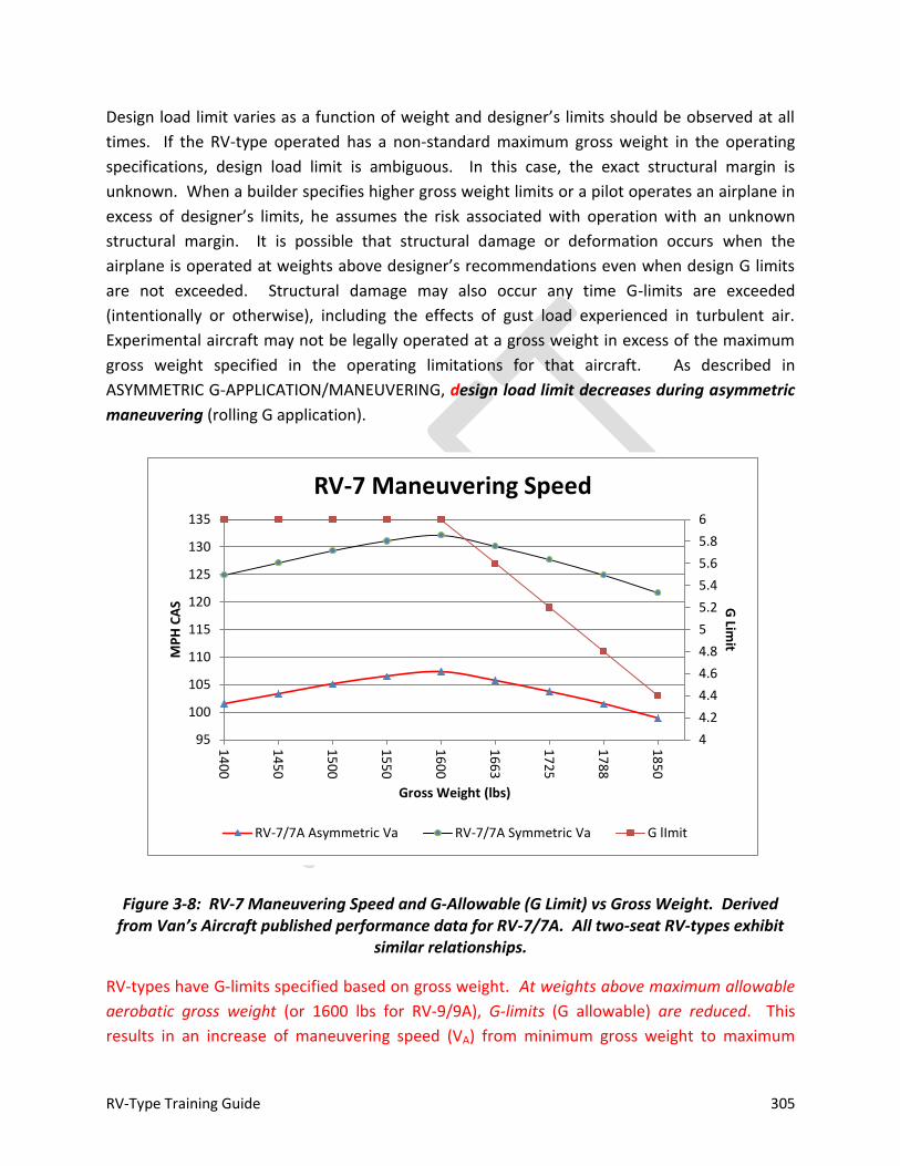
RV-Type Training Guide 305
Design load limit varies as a function of weight and designer’s limits should be observed at all
times. If the RV-type operated has a non-standard maximum gross weight in the operating
specifications, design load limit is ambiguous. In this case, the exact structural margin is
unknown. When a builder specifies higher gross weight limits or a pilot operates an airplane in
excess of designer’s limits, he assumes the risk associated with operation with an unknown
structural margin. It is possible that structural damage or deformation occurs when the
airplane is operated at weights above designer’s recommendations even when design G limits
are not exceeded. Structural damage may also occur any time G-limits are exceeded
(intentionally or otherwise), including the effects of gust load experienced in turbulent air.
Experimental aircraft may not be legally operated at a gross weight in excess of the maximum
gross weight specified in the operating limitations for that aircraft. As described in
ASYMMETRIC G-APPLICATION/MANEUVERING, design load limit decreases during asymmetric
maneuvering (rolling G application).
Figure 3-8: RV-7 Maneuvering Speed and G-Allowable (G Limit) vs Gross Weight. Derived from Van’s Aircraft published performance data for RV-7/7A. All two-seat RV-types exhibit
similar relationships.
RV-types have G-limits specified based on gross weight. At weights above maximum allowable
aerobatic gross weight (or 1600 lbs for RV-9/9A), G-limits (G allowable) are reduced. This
results in an increase of maneuvering speed (VA) from minimum gross weight to maximum
4
4.2
4.4
4.6
4.8
5
5.2
5.4
5.6
5.8
6
95
100
105
110
115
120
125
130
135
14
00
14
50
15
00
15
50
16
00
16
63
17
25
17
88
18
50
G Lim
it MP
H C
AS
Gross Weight (lbs)
RV-7 Maneuvering Speed
RV-7/7A Asymmetric Va RV-7/7A Symmetric Va G lImit
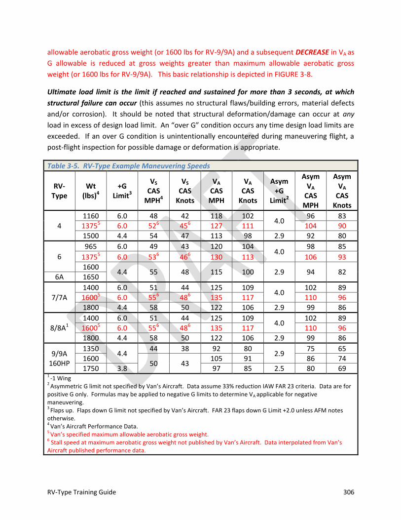
RV-Type Training Guide 306
allowable aerobatic gross weight (or 1600 lbs for RV-9/9A) and a subsequent DECREASE in VA as
G allowable is reduced at gross weights greater than maximum allowable aerobatic gross
weight (or 1600 lbs for RV-9/9A). This basic relationship is depicted in FIGURE 3-8.
Ultimate load limit is the limit if reached and sustained for more than 3 seconds, at which
structural failure can occur (this assumes no structural flaws/building errors, material defects
and/or corrosion). It should be noted that structural deformation/damage can occur at any
load in excess of design load limit. An “over G” condition occurs any time design load limits are
exceeded. If an over G condition is unintentionally encountered during maneuvering flight, a
post-flight inspection for possible damage or deformation is appropriate.
Table 3-5. RV-Type Example Maneuvering Speeds
RV-Type
Wt (lbs)4
+G Limit3
VS CAS
MPH4
VS
CAS Knots
VA CAS MPH
VA
CAS Knots
Asym +G
Limit2
Asym VA
CAS MPH
Asym VA
CAS Knots
4
1160 6.0 48 42 118 102 4.0
96 83
13755 6.0 526 456 127 111 104 90
1500 4.4 54 47 113 98 2.9 92 80
6
965 6.0 49 43 120 104 4.0
98 85
13755 6.0 536 466 130 113 106 93
1600 4.4 55 48 115 100 2.9 94 82
6A 1650
7/7A
1400 6.0 51 44 125 109 4.0
102 89
16005 6.0 556 486 135 117 110 96
1800 4.4 58 50 122 106 2.9 99 86
8/8A1 1400 6.0 51 44 125 109
4.0 102 89
16005 6.0 556 486 135 117 110 96
1800 4.4 58 50 122 106 2.9 99 86
9/9A 160HP
1350 4.4
44 38 92 80 2.9
75 65
1600 50 43
105 91 86 74
1750 3.8 97 85 2.5 80 69 1
-1 Wing 2
Asymmetric G limit not specified by Van’s Aircraft. Data assume 33% reduction IAW FAR 23 criteria. Data are for positive G only. Formulas may be applied to negative G limits to determine VA applicable for negative maneuvering. 3
Flaps up. Flaps down G limit not specified by Van’s Aircraft. FAR 23 flaps down G Limit +2.0 unless AFM notes otherwise. 4
Van’s Aircraft Performance Data. 5
Van’s specified maximum allowable aerobatic gross weight. 6 Stall speed at maximum aerobatic gross weight not published by Van’s Aircraft. Data interpolated from Van’s
Aircraft published performance data.
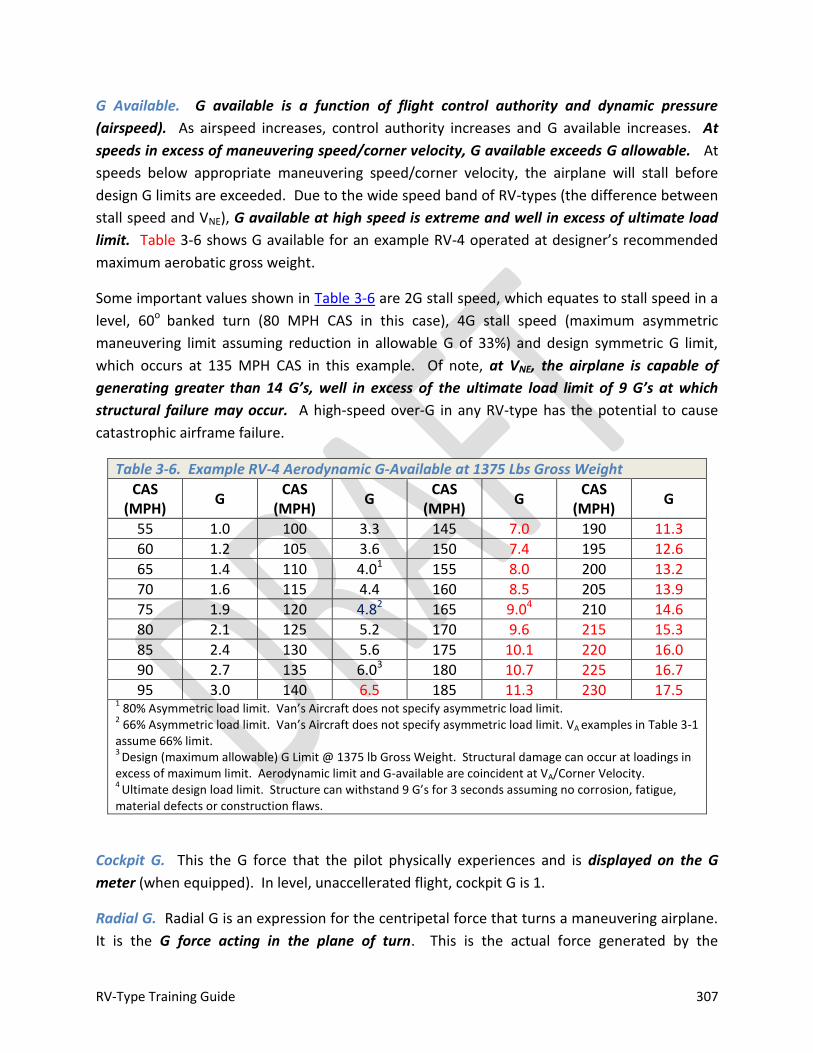
RV-Type Training Guide 307
G Available. G available is a function of flight control authority and dynamic pressure
(airspeed). As airspeed increases, control authority increases and G available increases. At
speeds in excess of maneuvering speed/corner velocity, G available exceeds G allowable. At
speeds below appropriate maneuvering speed/corner velocity, the airplane will stall before
design G limits are exceeded. Due to the wide speed band of RV-types (the difference between
stall speed and VNE), G available at high speed is extreme and well in excess of ultimate load
limit. Table 3-6 shows G available for an example RV-4 operated at designer’s recommended
maximum aerobatic gross weight.
Some important values shown in Table 3-6 are 2G stall speed, which equates to stall speed in a
level, 60o banked turn (80 MPH CAS in this case), 4G stall speed (maximum asymmetric
maneuvering limit assuming reduction in allowable G of 33%) and design symmetric G limit,
which occurs at 135 MPH CAS in this example. Of note, at VNE, the airplane is capable of
generating greater than 14 G’s, well in excess of the ultimate load limit of 9 G’s at which
structural failure may occur. A high-speed over-G in any RV-type has the potential to cause
catastrophic airframe failure.
Table 3-6. Example RV-4 Aerodynamic G-Available at 1375 Lbs Gross Weight
CAS (MPH)
G CAS
(MPH) G
CAS (MPH)
G CAS
(MPH) G
55 1.0 100 3.3 145 7.0 190 11.3
60 1.2 105 3.6 150 7.4 195 12.6
65 1.4 110 4.01 155 8.0 200 13.2
70 1.6 115 4.4 160 8.5 205 13.9
75 1.9 120 4.82 165 9.04 210 14.6
80 2.1 125 5.2 170 9.6 215 15.3
85 2.4 130 5.6 175 10.1 220 16.0
90 2.7 135 6.03 180 10.7 225 16.7
95 3.0 140 6.5 185 11.3 230 17.5 1 80% Asymmetric load limit. Van’s Aircraft does not specify asymmetric load limit.
2 66% Asymmetric load limit. Van’s Aircraft does not specify asymmetric load limit. VA examples in Table 3-1
assume 66% limit. 3
Design (maximum allowable) G Limit @ 1375 lb Gross Weight. Structural damage can occur at loadings in excess of maximum limit. Aerodynamic limit and G-available are coincident at VA/Corner Velocity. 4
Ultimate design load limit. Structure can withstand 9 G’s for 3 seconds assuming no corrosion, fatigue, material defects or construction flaws.
Cockpit G. This the G force that the pilot physically experiences and is displayed on the G
meter (when equipped). In level, unaccellerated flight, cockpit G is 1.
Radial G. Radial G is an expression for the centripetal force that turns a maneuvering airplane.
It is the G force acting in the plane of turn. This is the actual force generated by the

RV-Type Training Guide 308
component of lift that turns the airplane. For a level turn, the plane of the turn is coincident
with the horizon and we refer to the “horizontal component of lift.” This is an example of radial
G. In a loop, the plane of turn is vertical and the entire lift component is aligned with the plane
of the turn and radial G “turns” the airplane throughout the loop. For non-level maneuvering
flight, the plane of turn is roughly coincident with the lift vector (angle of bank).
Lift Vector. When describing maneuvering flight, it is helpful to understand the direction in
which lift is working. The “lift vector” refers to the direction that the wing generates lift,
roughly perpendicular to the wings. If the pilot is sitting upright in the cockpit, the lift vector is
acting in the direction his head is pointing. In a 45o banked level turn, the lift vector is angled
45o in the direction of the turn. In a split-S (180o bank), the lift vector is straight down,
conversely at the start of a loop, the lift vector is straight up. Cockpit G is applied in the
direction of the lift vector. Roll is the primary means to control lift vector placement. Once the
lift vector is positioned with roll, pitch controls the amount of lift generated (as a function of
dynamic pressure [airspeed] and AOA). This primary lift vector can be broken down into
components that cause the airplane to climb, descend or turn.
Velocity Vector. The term “velocity vector” refers to where the airplane is going. It is also
referred to as the flight path vector. These terms are interchangeable. If the RV-type is
equipped with advanced instrumentation, flight path vector may be displayed on the EFIS. If
the airplane is equipped with traditional instrumentation, velocity vector can only be
approximated. An important concept to understand is that where the airplane is going (flight
path vector) is not necessarily where the airplane is pointing.
A way to visualize the concept of velocity vector is to consider a 3o final approach to landing. In
this case, the descent angle is 3o, and the airplane is flying at Van’s recommended VREF (ON
SPEED [L/DMAX] or 1.3-1.4 x VS). For the 23000 series airfoil on the RV-4/6/7/8, L/DMAX occurs at
approximately 8o AOA. Assuming 1o angle of incidence, you can see that 9o of pitch is required
to maintain this flight condition. In other words, the velocity vector is 9o below where the nose
is pointing. Since the velocity vector is coincident with a 3o approach path in this example, the
nose of the RV would actually be 6o above the horizon in a stabilized condition (9 – 3 = 6). This
6o is the angle displayed on the artificial horizon (if equipped and properly adjusted). If the
airplane is equipped with advanced instrumentation and the flight path vector is displayed, it
will be 3o below the horizon and 9o below the whiskey line/boresite cue (i.e., where the nose is
pointed). If it were necessary to level off, it would be necessary to increase pitch by 3o (and add
power) if L/DMAX is maintained. If the airplane is equipped with advanced instrumentation and
the flight path vector is displayed, it will “transition” up to the horizon during the level-off
maneuver and the whiskey line/boresite cue will transition to a 9o nose up attitude (assuming
RV-Type Training Guide 309
L/DMAX is maintained) During approach, the velocity vector is coincident with the point in the
windscreen that is neither moving up or down.
In the previous example, it’s easy to visualize the difference between where the airplane is
pointed and the velocity vector since the airplane is in a stable condition. During maneuvering
flight, it is not always as straight forward unless you are maneuvering 90o nose up or nose
down, in which case the velocity vector is roughly coincident with the nose. Of course, if a 90o
nose up condition is maintained, the velocity vector is going to rapidly transition to the tail as
airspeed decays to zero. Another example is a sustained deep stall. In this case, the airplane is
actually “falling” at a fairly steep angle, yet the nose is roughly coincident with the horizon.
A special case of velocity vector management occurs when the pilot establishes a zero G
condition. Any time the pilot unloads to a zero G condition, he is actively aligning the nose with
the velocity vector and establishing a ballistic condition. For example, if maneuvering resulted
in a steep climb angle (say, 70o), airspeed is going to rapidly decay if that climb angle is
maintained since there isn’t sufficient thrust in any RV-type to sustain a 70o climb angle. If,
however, the pilot neutralizes aileron and rudder input and eases the stick forward to establish
a zero G condition, the nose and velocity vector will re-align and the airplane will simply float
across a ballistic arc. Airspeed may decay well below 1G stall speed; but will increase as soon as
the arc transitions to a nose down condition and the velocity vector drifts below the horizon.
This is an important concept and is the key to the “unload for control” concept that allows the
pilot to “bail-out” of any condition that could result in stall and subsequent post-stall departure
from controlled flight.
One of the most important RV-type handling characteristics to understand is that any time
the velocity vector is below the horizon and the nose is down, the airplane will accelerate due
to low drag characteristics of the design. Acceleration can occur rapidly, possibly to dangerous
speeds. This acceleration should be anticipated, and if excessive airspeed build-up is
encountered, the pilot must reduce power, simultaneously adjust G load and reposition the lift
vector (if necessary) and velocity vector above the horizon, to prevent a dangerous buildup of
airspeed. Note that a fixed pitch propeller will behave like a pinwheel under these conditions
and an engine over-speed can also occur.
Maneuvering Summary
Maneuvering is limited by structure and the ability to produce lift and thrust. Designer’s
limiting load factor and weight and balance limits should be adhered to at all times. G-
allowable should be reduced 20-33% when applying asymmetric flight controls (i.e.,
simultaneous maneuvering about two axis). Fastest roll rates occur during unloaded (0 G)
flight. Radial G is the amount of lift (expressed in G’s) that acts to turn the airplane. Lift vector

RV-Type Training Guide 310
is coincident with the plane of symmetry and acts perpendicular to the wings. Any time the lift
vector is above the horizon, natural gravity is reducing radial G/turn performance and any time
the lift vector is below the horizon, natural gravity is increasing radial G/turning performance.
The radius of turn depends solely on velocity (TAS), G and radial G. Turn radius is the
dimension of the turn circle. Turn rate is solely dependent on velocity (TAS) and radial G. Turn
rate is how fast the nose cuts across the sky and is expressed in degrees per second: the
greater the G-available, the higher the turn rate. No other variables (such as wing loading or
gross weight) are a factor in turn performance. All RV-types exhibit outstanding turn
performance and maneuverability.
TURN PERFORMANCE
Level Turns. The airplane turns as a result of adjustment of the lift vector (bank) to produce a
horizontal component of lift (radial G). This produces a centripetal force that causes the
airplane to turn. To prevent a loss of altitude, back stick (increasing AOA/CL) is required
increasing the overall magnitude of the lift vector. This is experienced in the cockpit as
increased G loading. For medium and shallow bank angles, the G load is low and only a small
amount of back pressure is required to maintain altitude. If power is not adjusted in a turn and
bank angle (and, subsequently, G) is increased an airspeed “bleed” will occur as angle-of-attack
increases and the indicated airspeed will decrease until a new equilibrium is established (or a
stall occurs). At medium and shallow bank angles (30 degrees or less), this amount of energy
loss (airspeed decrease) is negligible in RV-types. As bank and G increase, the amount of energy
loss becomes much greater.
The only factors that affect turn rate and radius for any airplane are radial G and true
airspeed. The relationship between bank angle and true airspeed and their effect on turn
radius for an example RV-type in a level turn is depicted in Figure 3-9.
Maneuvering may be defined as changing the magnitude and/or direction of the aircraft’s
velocity vector. Maneuvering is conducted about all three aircraft axes. “Unloaded”
maneuvering is the application of flight controls in a low G (0 ± ½ G) condition about a single
axis at a time. An example of unloaded maneuvering is a simple aileron roll—after obtaining
entry speed, the pitch is increased, the stick is eased forward to unload and then aileron is
applied to rotate the lift vector. “Loaded” maneuvering occurs under G when a flight control
or controls are applied. An example of a loaded maneuver is a high AOA rudder roll. In this
case, G is applied in pitch to increase AOA and rudder is simultaneously applied in the direction
of desired roll. Yaw/roll coupling causes the airplane to roll slowly in the direction in which
rudder is applied. A barrel roll is another example of loaded maneuvering.
The following factors impact maneuvering:
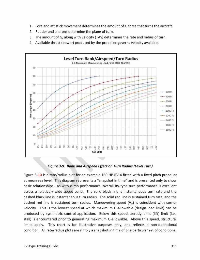
RV-Type Training Guide 311
1. Fore and aft stick movement determines the amount of G force that turns the aircraft.
2. Rudder and ailerons determine the plane of turn.
3. The amount of G, along with velocity (TAS) determines the rate and radius of turn.
4. Available thrust (power) produced by the propeller governs velocity available.
Figure 3-9. Bank and Airspeed Effect on Turn Radius (Level Turn)
Figure 3-10 is a rate/radius plot for an example 160 HP RV-4 fitted with a fixed pitch propeller
at mean sea level. This diagram represents a “snapshot in time” and is presented only to show
basic relationships. As with climb performance, overall RV-type turn performance is excellent
across a relatively wide speed band. The solid black line is instantaneous turn rate and the
dashed black line is instantaneous turn radius. The solid red line is sustained turn rate, and the
dashed red line is sustained turn radius. Maneuvering speed (VA) is coincident with corner
velocity. This is the lowest speed at which maximum G-allowable (design load limit) can be
produced by symmetric control application. Below this speed, aerodynamic (lift) limit (i.e.,
stall) is encountered prior to generating maximum G-allowable. Above this speed, structural
limits apply. This chart is for illustrative purposes only, and reflects a non-operational
condition. All rate/radius plots are simply a snapshot in time of one particular set of conditions.

RV-Type Training Guide 312
The chart represents theoretical maximum performance capability. The instantaneous plot
results in extremely high energy bleed rates that cannot be sustained. Instantaneous corner
velocity is the minimum speed at which maximum G-allowable can be obtained, i.e., the
quickest, tightest turn. There is insufficient power available to maintain this condition, so
airspeed will decay rapidly when performing this type of turn. Furthermore, if G-onset rate
(i.e., back stick) is insufficient, maximum allowable G may not be obtained before speed decays
to a point that insufficient lift reserve remains to reach maximum G allowable.
Figure 3-10. Example Turn Rate/Radius Diagram for an RV-4. Instantaneous turn performance is black and sustained turn performance is red. Turn rate (deg/sec) are the hill
shaped curves and turn radius (feet) are the valley shaped curves. Maximum rate and minimum radius = best turn performance.
The sustained plot represents a 0 PS (zero specific excess power or a neutral energy) condition.
In other words, the airplane has sufficient thrust to maintain this turn condition. Sustained
Warning
Sufficient elevator authority exists in all RV-types to allow an over-G condition to occur if aft stick is applied too rapidly at speeds above corner velocity (VA). The flight control system is capable of generating dangerously high G loads at high airspeed with improper control input.

RV-Type Training Guide 313
corner velocity is the speed at which a maximum, sustained rate of turn can be achieved
without an accompanying loss of speed or altitude. PS (specific excess power) values represent
the ability of the airplane to change its energy state. A positive PS refers to the ability to
accelerate and/or climb, while a negative value means the airplane is slowing down and/or
losing altitude. Best overall turn performance for the example 160 HP RV-4 is obtained
between 90-135 MPH CAS, with best sustained radius performance on the low side of this band
and an average sustained rate of turn of approximately 30 degrees/second across the band.
Best range glide speed is roughly coincident with the bottom of the optimum turn band. Of
note, best sustained turn performance occurs at speeds at and BELOW corner velocity (VA).
Figure 3-11. Constant 3 G Vertical Turn
Vertical Turn Performance. The purest form of a vertical turn is a constant cockpit G loop (or
portion thereof). This is depicted in Figure 3-11. Since turn performance is a function of radial
G and TAS, and radial G will vary throughout, this affects actual turn performance and causes a
vertical turn to be shaped like an egg. In the example depicted in Figure 3-9, the pilot applies 3
G’s at the start of the maneuver and maintains 3 G’s on the g-meter throughout the maneuver.
At the bottom of the loop, 1 G is required to maintain altitude, so only 2 radial G’s are available
2 Radial G
4 Radial G
3 Radial G3 Radial G
1 G

RV-Type Training Guide 314
to turn the airplane. As the airplane approaches 90o of pitch, all cockpit G is available for
turning the airplane (3 radial G’s). When the airplane is inverted at the top of the loop, the 3
cockpit G’s are added to actual force of gravity and 4 radial G’s are available to turn. On the
“back side” of the loop as the airplane once again achieves 90o nose low, radial G once again
equals cockpit G, but as pitch decreases below 90o nose low, radial G begins to decrease and
turn performance decreases. As the loop is completed, 2 radial G’s remain.
Turn Performance Summary
Only two factors affect turn performance: radial G and TAS. As weight and/or altitude
increase, overall turn performance will decrease. Actual turn performance will vary from
airplane to airplane, with the greatest single factor affecting performance being thrust available
(a function of engine/propeller combination), all other factors equal. If flight test data is not
available for a specific aircraft, actual turn performance cannot be plotted; however, RV-types
offer overall excellent overall turn performance, especially between 80 MPH / 75 Knots and VA.
ENERGY MANAGEMENT
Overall, maneuvering flight can be thought of in terms of energy management. In its simplest
form, energy is simply a combination of altitude, airspeed and excess power (thrust) available.
Under engine-out conditions, it’s just the combination of altitude and airspeed. Observing
some basic rules of thumb and flying through planned “hoops” (known energy points) can
greatly assist with developing a feel for proper energy management. Examples of known
energy points are entry parameters for advanced handling maneuvers, high key, properly
computed VA, low key or final roll-out points in a flame-out/power-off pattern. If a pilot simply
does what it takes to fly through a known energy point on parameters, there will be sufficient
energy to execute the desired maneuver, whether that’s a loop, wing-over, etc. or power-off
landing. As experience is gained, the upgrading pilot will become more adept at real-time
assessment of energy.
MAXIMUM STRUCTURAL CRUISING SPEED
Maximum structural cruising speed (VN0) is coincident with the top of the green arc on the
airspeed indicator. It is the maximum speed for normal operation. Most RV-types are capable
of exceeding maximum structural cruising speed in level flight. This speed should only be
exceeded in smooth air.
Be alert for weather conditions which will cause increasing turbulence when making descents
from cruising altitude, especially during daylight operations. It is common for turbulence to
increase near the surface. One consideration is any fair weather cumulus formations, air is
RV-Type Training Guide 315
generally bumpy beneath the cloud bases (due to updrafts causing cloud formation); so if these
clouds are observed below, be prepared to slow down to observe speed limits and maintain
comfort. It should be noted that in some cases, never exceed speed expressed as CAS can be
LESS than VNO (See NEVER EXCEED SPEED).
NEVER EXCEED SPEED
Never exceed speed (VNE) is also referred to as “red line” speed since it is marked on the
airspeed indicator with a red line. It is coincident with the top of the yellow arc on a properly
marked airspeed indicator. Airspeed indicators, whether conventional or advanced displays,
show dynamic pressure by measuring the difference between pitot and static pressure. Stall
speed, maximum structural cruising speed and maneuvering speed are a function of dynamic
pressure and thus, indicated airspeed. Never exceed speed (VNE) is a function of true airspeed
and is thus only marginally represented by the red line depicted on the airspeed indicator. As
altitude and true airspeed increase, indicated airspeed will decrease or, put another way, for a
given indicated airspeed, true airspeed will increase with altitude. Due to the low drag and
high speed ratio of RV-types, even a moderate descent angle from altitude at normal cruise
power is capable of generating true airspeeds in excess of design VNE. Some RV-types are
capable of exceeding VNE in level flight, depending on engine and propeller fitted.
The pilot must be aware of true airspeed and be prepared to adjust “red line” speed based on
altitude. One technique is to never exceed maximum structural cruising speed (although this
rule of thumb breaks down at altitudes above about 12,000 feet at temperatures warmer than
standard). Another is to calculate TAS based on ambient conditions and observe that limit. If
the aircraft is not equipped with a TAS indicator, TAS can be roughly approximated by adding 3
knots/MPH to CAS for each 1000’ of altitude. Some advanced instrumentation systems
equipped with an air data computer may display TAS in the cockpit. In aircraft equipped with
properly calibrated and tested advanced instrumentation, observe VNE by reference to the TAS
display.
Flutter. The difference in TAS between which flutter occurs and actual speed is referred to as
flutter margin. As actual TAS increases, flutter margin decreases, eventually reaching a critical
speed that will result in aerodynamic flutter that could potentially be catastrophic. Depending
on ambient conditions and gust load, aerodynamic flutter can cause nearly instantaneous
failure of the primary structure of the airplane without warning. Van’s aircraft has performed
ground vibration tests to demonstrate good flutter margins throughout the design envelope of
RV-types. Flutter may manifest itself as a high frequency airframe vibration with the stick
vibrating/shaking a commensurate amount. If this phenomenon is encountered, it is
imperative to slow down immediately. Power should be reduced and a gentle maneuver
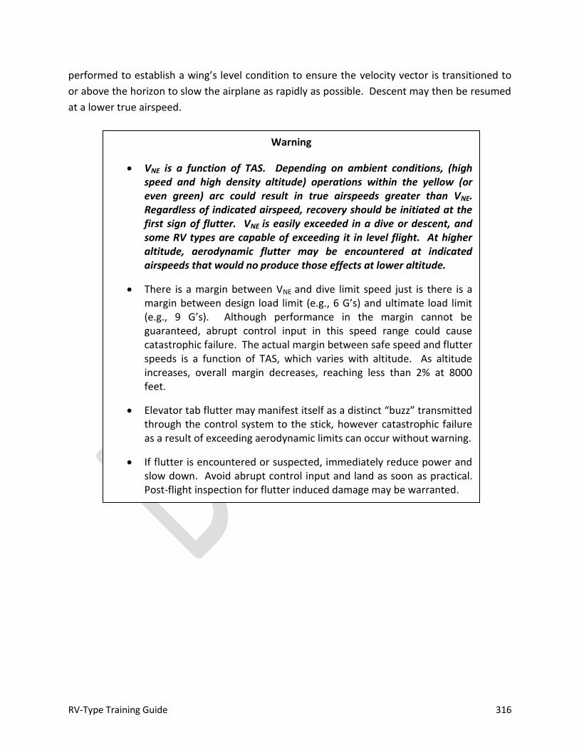
RV-Type Training Guide 316
performed to establish a wing’s level condition to ensure the velocity vector is transitioned to
or above the horizon to slow the airplane as rapidly as possible. Descent may then be resumed
at a lower true airspeed.
Warning
VNE is a function of TAS. Depending on ambient conditions, (high speed and high density altitude) operations within the yellow (or even green) arc could result in true airspeeds greater than VNE. Regardless of indicated airspeed, recovery should be initiated at the first sign of flutter. VNE is easily exceeded in a dive or descent, and some RV types are capable of exceeding it in level flight. At higher altitude, aerodynamic flutter may be encountered at indicated airspeeds that would no produce those effects at lower altitude.
There is a margin between VNE and dive limit speed just is there is a margin between design load limit (e.g., 6 G’s) and ultimate load limit (e.g., 9 G’s). Although performance in the margin cannot be guaranteed, abrupt control input in this speed range could cause catastrophic failure. The actual margin between safe speed and flutter speeds is a function of TAS, which varies with altitude. As altitude increases, overall margin decreases, reaching less than 2% at 8000 feet.
Elevator tab flutter may manifest itself as a distinct “buzz” transmitted through the control system to the stick, however catastrophic failure as a result of exceeding aerodynamic limits can occur without warning.
If flutter is encountered or suspected, immediately reduce power and slow down. Avoid abrupt control input and land as soon as practical. Post-flight inspection for flutter induced damage may be warranted.
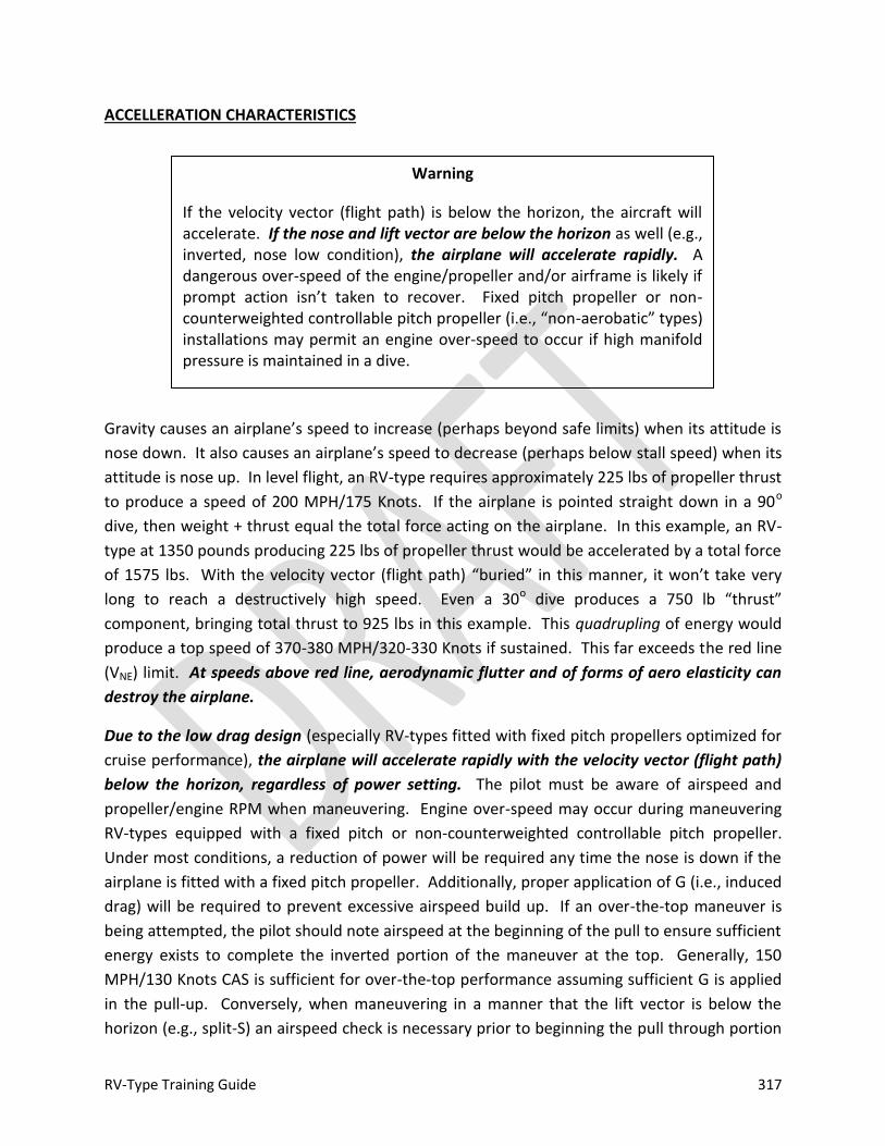
RV-Type Training Guide 317
ACCELLERATION CHARACTERISTICS
Gravity causes an airplane’s speed to increase (perhaps beyond safe limits) when its attitude is
nose down. It also causes an airplane’s speed to decrease (perhaps below stall speed) when its
attitude is nose up. In level flight, an RV-type requires approximately 225 lbs of propeller thrust
to produce a speed of 200 MPH/175 Knots. If the airplane is pointed straight down in a 90o
dive, then weight + thrust equal the total force acting on the airplane. In this example, an RV-
type at 1350 pounds producing 225 lbs of propeller thrust would be accelerated by a total force
of 1575 lbs. With the velocity vector (flight path) “buried” in this manner, it won’t take very
long to reach a destructively high speed. Even a 30o dive produces a 750 lb “thrust”
component, bringing total thrust to 925 lbs in this example. This quadrupling of energy would
produce a top speed of 370-380 MPH/320-330 Knots if sustained. This far exceeds the red line
(VNE) limit. At speeds above red line, aerodynamic flutter and of forms of aero elasticity can
destroy the airplane.
Due to the low drag design (especially RV-types fitted with fixed pitch propellers optimized for
cruise performance), the airplane will accelerate rapidly with the velocity vector (flight path)
below the horizon, regardless of power setting. The pilot must be aware of airspeed and
propeller/engine RPM when maneuvering. Engine over-speed may occur during maneuvering
RV-types equipped with a fixed pitch or non-counterweighted controllable pitch propeller.
Under most conditions, a reduction of power will be required any time the nose is down if the
airplane is fitted with a fixed pitch propeller. Additionally, proper application of G (i.e., induced
drag) will be required to prevent excessive airspeed build up. If an over-the-top maneuver is
being attempted, the pilot should note airspeed at the beginning of the pull to ensure sufficient
energy exists to complete the inverted portion of the maneuver at the top. Generally, 150
MPH/130 Knots CAS is sufficient for over-the-top performance assuming sufficient G is applied
in the pull-up. Conversely, when maneuvering in a manner that the lift vector is below the
horizon (e.g., split-S) an airspeed check is necessary prior to beginning the pull through portion
Warning
If the velocity vector (flight path) is below the horizon, the aircraft will accelerate. If the nose and lift vector are below the horizon as well (e.g., inverted, nose low condition), the airplane will accelerate rapidly. A dangerous over-speed of the engine/propeller and/or airframe is likely if prompt action isn’t taken to recover. Fixed pitch propeller or non-counterweighted controllable pitch propeller (i.e., “non-aerobatic” types) installations may permit an engine over-speed to occur if high manifold pressure is maintained in a dive.

RV-Type Training Guide 318
of the maneuver to ensure that a dangerous acceleration won’t occur. After the lift vector has
been positioned, a smooth, rapid pull should be utilized to established desired G/nose rate. In
general, if the indicated airspeed is greater than 110 MPH/95 Knots CAS in a 180o bank
(inverted) and the nose passing down through the horizon, a vertical pull-through should not be
attempted, but rather the airplane should be rolled up right and recovered to level flight.
ENGINE AND PROPELLER EFFECTS
Figure 3-12: Propeller Effect—Spiraling Slipstream
The engine and propeller effect handling characteristics. There will be variation from airplane
to airplane due to different engine/propeller combinations fitted. The amount and proportion
of these effects vary with power setting and airspeed. There are three propeller effects:
slipstream effect, p-factor, and gyroscopic precession. The engine effect is torque. These
effects are depicted in Figures 3-12 through 3-16. With the exception of gyroscopic precession,
the overall tendency of these effects is to cause yaw and roll to the left when viewed from the
cockpit. In RV-types, these effects are most noticeable at high power, low airspeed. Slipstream
effect (impact of the spiral slipstream generated by the propeller and wrapping around the
airplane as it moves aft) impacts the aft, left fuselage and tail, imparting a left yaw when
viewed from the cockpit. It also induces a slightly higher AOA on the left wing root than the
right root (Figure 3-12). P-factor moves the aerodynamic center of the propeller to the right of
the crankshaft axis, causing the aircraft to yaw left (viewed from the cockpit) as AOA or power
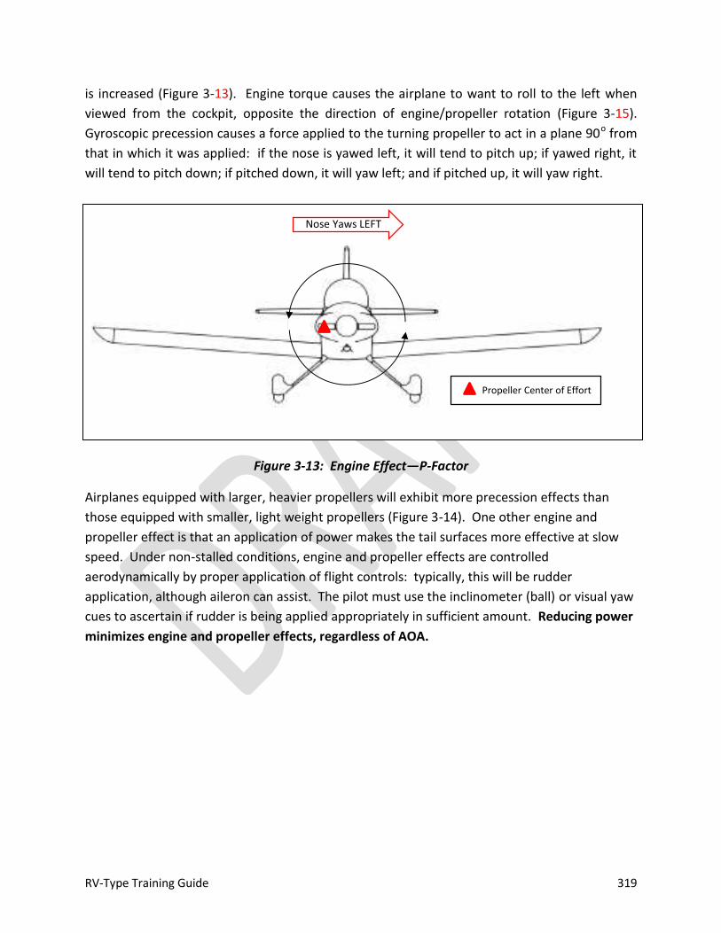
RV-Type Training Guide 319
is increased (Figure 3-13). Engine torque causes the airplane to want to roll to the left when
viewed from the cockpit, opposite the direction of engine/propeller rotation (Figure 3-15).
Gyroscopic precession causes a force applied to the turning propeller to act in a plane 90o from
that in which it was applied: if the nose is yawed left, it will tend to pitch up; if yawed right, it
will tend to pitch down; if pitched down, it will yaw left; and if pitched up, it will yaw right.
Figure 3-13: Engine Effect—P-Factor
Airplanes equipped with larger, heavier propellers will exhibit more precession effects than
those equipped with smaller, light weight propellers (Figure 3-14). One other engine and
propeller effect is that an application of power makes the tail surfaces more effective at slow
speed. Under non-stalled conditions, engine and propeller effects are controlled
aerodynamically by proper application of flight controls: typically, this will be rudder
application, although aileron can assist. The pilot must use the inclinometer (ball) or visual yaw
cues to ascertain if rudder is being applied appropriately in sufficient amount. Reducing power
minimizes engine and propeller effects, regardless of AOA.
N
Propeller Center of Effort
Nose Yaws LEFT
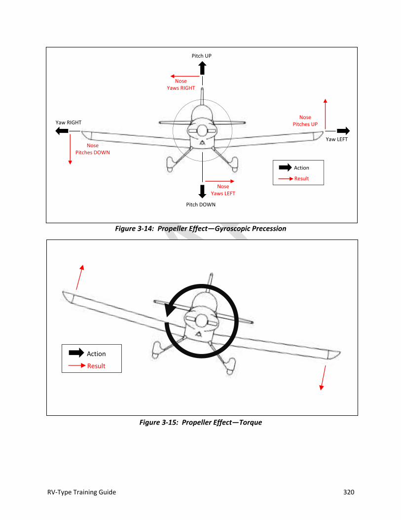
RV-Type Training Guide 320
Figure 3-14: Propeller Effect—Gyroscopic Precession
Figure 3-15: Propeller Effect—Torque
Nose Yaws RIGHT
Nose Yaws LEFT
Yaw RIGHT Nose
Pitches UP
Pitch UP
Yaw LEFT
Pitch DOWN
Nose Pitches DOWN
Action
Result
Action
Result

RV-Type Training Guide 321
STABILITY CHECK
Prior to maneuvering flight, a basic flight control/stability check should be conducted. If the
airplane is loaded within appropriate design limits, proper aircraft response to a stability check
will ensure adequate stability and proper response to flight controls is available to safely
perform confidence and advanced handling maneuvers. To perform the stability check, ensure
lose items are stowed and harnesses are properly adjusted (tight). Establish a stabilized
condition and power setting in smooth air (cruise climb or straight and level flight).
Pitch Check. Note trimmed stick position, then smoothly apply back stick to reduce indicated
airspeed 10 Knots/MPH. Release longitudinal pressure on the stick and note pitch response.
The airplane should nose down and airspeed will increase above the initial trim condition. Then
the nose will rise again. Pitch oscillations will damp in 3-4 cycles. One cycle is sufficient to
confirm proper response. As a technique, returning the stick to the noted trim position after
the initial application of back pressure and noting pitch response will accomplish the same thing
and result in less overshoots. Be alert for divergent behavior (i.e., airspeed continues to
decrease/nose continues to rise after initial input).
Roll Check. Trim for wing’s level flight. Check fuel balance (less than 6 gallons desired). Roll
the airplane into 30-45o of bank and relax lateral stick pressure. The airplane should maintain
the bank angle or slowly trend toward wing’s level (neutral or positive lateral stability).
Divergent behavior is not normal, but lateral stability will decrease if there is a significant
imbalance in fuel (i.e., a heavy wing).
Yaw Check. Trim for wing’s level flight. Smoothly apply rudder to yaw the airplane in one
direction and quickly release rudder pressure, keeping feet off the pedals. The airplane should
immediately return to aligned flight. It is possible that an overshoot will occur (i.e., the airplane
“fish tails”). Typically, 4-6 overshoots of decreasing intensity will occur before the input will
damp out. Any roll left or right during this check is normal. Divergent behavior is not normal.
If divergent behavior is encountered during any portion of the stability check (other than roll
due to a heavy wing), maneuvering flight and stalls should not be performed.
RV-Type Training Guide 322
UNUSUAL ATTITUDES/UPSET RECOVERY
Because of the low drag design and large speed range of RV-types, it is essential to interpret
and correct unusual attitudes as rapidly as possible. Control movements and AOA control must
be smooth, especially in nose high, low airspeed conditions to prevent an out-of-control
situation; and G-application must be smooth and positive in nose low conditions to prevent
dangerously high speeds, engine over-speed and/or over-G. Advanced instrumentation
systems MAY provide reliable attitude information through 360 degrees of pitch and roll.
Unload for Control Concept. One key aircraft handling skill set is the ability to fly the airplane in
a manner to avoid a loss of control, regardless of attitude. Simply put, any time a loss of control
(stall, etc.) is impending, neutralizing aileron and rudder then smoothly unloading the airplane
to a 0 to ½ positive G condition will most likely restore controlled flight, provided sufficient
altitude exists. When unloaded to zero G, the airplane will not stall. The aircraft is no longer
out-of-control when unloaded to 0 to ½ positive G and airspeed is increasing. This recovery
technique may result in an unusual attitude during the recovery phase; but will reliably avoid
auto-rotation if properly applied.
Regardless of attitude, if an impending loss of control is evident (buffet, rapidly decreasing
airspeed, etc.), neutralize rudder and aileron and then reduce AOA (ease the stick forward).
First neutralize aileron; then ease forward. Visually cross-check stick position, if required.
Regardless of technique employed, control inputs must be SMOOTH and DELIBERATE. Never
slam the stick forward. Power reduction depends on circumstances. For a simple airspeed
decay in level flight or, perhaps, the base turn to final, unloading (relaxing the stick
pressure/reducing AOA) will rapidly restore controlled flight. If, on the other hand,
maneuvering at high power is being conducted (e.g., aerobatics), then reducing power to idle
Note
FAR 91.307 states that unless each occupant of the aircraft is wearing an approved parachute, no pilot of a civil aircraft carrying any person other than a crew member may execute any intentional maneuver that exceeds 60o of bank or ± 30o pitch. The parameters only apply to the requirement for wearing a parachute and do not constitute a definition of aerobatic flight (AC 61-67C makes an exception for the conduct of spin training). FAR 91.303 defines aerobatic flight as intentional maneuver involving an abrupt change in an aircraft's attitude, an abnormal attitude, or abnormal acceleration, not necessary for normal flight.

RV-Type Training Guide 323
while simultaneously neutralizing controls may assist in maintaining control (“idlize and
neutralize,” see EMERGENCY PROCEDURES, OUT-OF-CONTROL).
In maneuvering situations with high pitch angles or during inverted flight, unloading to 0 G or
less may result in a loss of power if the airplane is not equipped with inverted systems and/or
has a carbureted engine. This is normal and should be anticipated. For aircraft without
inverted systems/fuel injection, a recovery at +¼ to +½ G is just about as effective as a zero G
condition and may allow the engine to continue running (or at least facilitate a windmill restart)
and minimize oil loss. For airplanes without inverted systems, engine hesitation actually serves
as a de facto G-meter that can assist with maintaining “eyes out” during recovery. If the
airplane is equipped with a G-meter, it may be referenced during recovery; however the pilot
should attempt to control G through feel. In addition to possible cues from a non-inverted
engine, a “heels light” feeling on the rudder pedals, or a feeling of becoming light in the seat is
ideal. If lose items in the cockpit start to float a true zero G condition has been established.
Under these conditions, the airplane is ballistic and will fly a ballistic arc. Due to the relatively
low airspeed and high turn rates of RV-types, the amount of time spent ballistic is generally
minimal, and the pilot must be alert for recovery cues (aircraft unloaded [0 to +½ G], airspeed
increasing) and transition to unusual attitude recovery. As a rule of thumb, degrees nose up
will equal degrees nose down during a ballistic recovery. For example, if the unload is
performed with the nose up 60 degrees and airspeed rapidly decaying, recovery will occur
about 60 degrees nose low.
The airplane is once again under control when unloaded to 0 to ½ positive G and airspeed is
increasing through 100 MPH/90 Knots.
Nose High, Airspeed Decreasing/Low Airspeed Recovery. If the nose is high and airspeed is
decaying, select full throttle if engine and propeller effects are not a factor, neutralize ailerons
and apply only enough rudder to maintain coordinated flight while establishing a low G
condition. If the engine hesitates (non-inverted systems) or the pilot’s feet or other items begin
to float in the cockpit, smoothly apply a small amount of back pressure to stabilize in a zero to
+½ G condition. Maintain 0 to +½ G condition until a safe flying airspeed (approximately 100
MPH/90 Knots) is reached. Then adjust bank, pitch and power to attain the desired flight
attitude. While maintaining low G, bank may be adjusted with aileron to facilitate recovery.
The most rapid recovery will be assured if a 90o bank is maintained until approaching flying
airspeed. If full throttle is applied during the initial stage of the recovery and the engine
continues to operate normally throughout the recovery, RPM and acceleration will need to be
monitored when the velocity vector has dropped below the horizon as it may be necessary to
reduce power as the airplane begins to accelerate nose low. If power was reduced during the
RV-Type Training Guide 324
initial event or during subsequent acceleration, be sure to readjust as the velocity vector is once
again on or above the horizon after recovery.
Nose Low, Airspeed Increasing or High Airspeed. Select idle power. With the velocity vector
below the horizon and the nose low, RV-types will accelerate very rapidly, and are capable of
reaching dangerous airspeed quickly. For airplanes equipped with fixed pitch propellers, if
power is not adjusted to idle, an engine over-speed is very likely. Idle power will also help
control airspeed build-up regardless of propeller type fitted, however proper, smooth
application of G (drag created by lift) will be critical to maintain airspeed within limits. To
recover, roll wings level and apply back pressure to pull the nose up to establish level flight. Do
not increase G until the bank is less than 90 degrees. For minimum altitude loss, maintain
airspeed at or below maneuvering speed and apply G as necessary to hold that speed (not to
exceed maximum allowable G). Be aware of any buffet during the pull-out as the airplane has
considerable elevator authority and is capable of generating sufficient pitch rates at low G to
induce a secondary stall. If buffet is encountered, the pilot should stabilize the G until airspeed
increases (buffet decreases) and/or a safe attitude is established. Airspeed cross-check is
critical throughout recovery. Above maneuvering speed (VA) the airplane is capable of
generating G well in excess of allowable limits. If speed is above maneuvering speed and
increasing, do not delay G input once 90 degrees of bank or less is reached. At speeds greater
than maximum structural cruising speed (VNO/top of the green arc of a properly marked
airspeed indicator), even greater care must be taken when applying G. As with any type of
maneuvering flight, smooth control input is critical. Abrupt control inputs applied at high speed
could cause high instantaneous G and catastrophic airframe failure.
Note
If in doubt, it is safer to establish a zero-G condition (allowing the engine to quit if necessary) and wait for the nose to drop and airspeed to increase. An air start may be accomplished after control is regained. In airplanes equipped with fixed pitch, light weight propellers, a prop-stopped condition may occur due to the low inertia of the propeller. Under these conditions, bumping the starter will be more expeditious than diving to windmill a stopped propeller.
For typical fuel systems, some fuel odor may be noted in the cockpit under these conditions. This is due to fuel venting and is normal.
RV-Type Training Guide 325
Emergency Dive Recovery. Altitude lost in a dive recovery is a function of radial G applied by
the pilot and TAS throughout the recovery. Maximum turning performance is obtained at
corner velocity/maneuvering speed (VA). A fixed-pitch propeller is of little aid in increasing
plate drag, so use of power in the dive depends on airspeed/buffet/G and speed relative to
corner; but as a general rule, power should be at idle for airplanes equipped with a fixed pitch
propeller. Drag produced by constant speed types may assist in controlling airspeed build up.
A maximum performance, minimum-radius, limit-load pull up is accomplished by a smooth,
quick pull to CLMAX (indicated by buffet [AOA]), until reaching corner speed (VA) , then remain at
limit load (maximum G-allowable) until recovery. One of the most common errors during
recovery is slow application of back stick during the initial phase of the recovery and an
unnecessarily rapid increase in airspeed. Operation at CLMAX (below corner/VA) or maximum G
allowable (above corner/VA) will help control airspeed build up by creating maximum induced
drag (drag due to the creation of lift). Buffet cues vary with airspeed and load, and if any nose
slice (yaw) is encountered or the nose stops tracking, AOA should be eased since those are
positive indications that CLMAX/AOACRIT has been exceeded (i.e., an accelerated stall is
occurring). Longitudinal stick position (i.e., amount of pull required) will vary throughout the
recovery: as the nose begins to transition up to the horizon, back pressure will have to be eased
to maintain maximum AOA or allowable G load. If it becomes apparent that red line speed
(VNE) will be exceeded during recovery, continue the smooth pull with the throttle in idle—do
not panic and increase pull abruptly as this will only aggravate the problem. The recovery pull
should continue until the velocity vector is above the horizon following pull out. The aircraft
can continue in a shallow climb to assist with deceleration after recovery.
INTENTIONAL SPINS
Warning
Unless flight tested, precise spin characteristics for a specific airplane are unknown.
There are significant aircraft to aircraft differences depending on CG, prop, control rigging, construction alignment, fairing configuration, etc.
Even when loaded within designer’s limits for aerobatic flight, minor differences in the aerodynamic profile of a specific airplane can have an effect on spin and spin recovery characteristics.

RV-Type Training Guide 326
When loaded within designer’s limits, RV-types will not generally auto-rotate (spin) unless
forced to do so by deliberate pro-spin application of controls. Factory prototype aerobatic RV-
types have been spin tested at designer’s acrobatic load limits and have demonstrated
conventional spin characteristics. All RV-type factory prototypes demonstrated satisfactory
recovery utilizing conventional recovery techniques when loaded within design aerobatic limits.
Side-by-side types exhibit different autorotation characteristics than tandem types. Individual
RV-types must be flight tested to determine suitability for use in spin training. Experimental
Amateur Built aircraft do not conform to any type certificate nor do they exhibit performance
(including spin recovery) commensurate with any category of certified aircraft, furthermore,
each aircraft is unique. Operating Limitations specify approved maneuvers for individual RV-
type aircraft.
RV-types are hesitant to spin and initiation of significant sideslip near the stall is required to
initiate auto-rotation with a full, erect spin developing should pro-spin controls be held. Spins
in both directions exhibit reasonably similar characteristics with rotation rate steadily
increasing and attitude flattening slightly with an increase number of turns. Engine and
propeller effects make entry easier for left-hand turns. Side-by-side types tend to exhibit flatter
spin characteristics than tandem types. Power-on spins exhibit a flatter attitude than power-off
spins. Pilot disorientation is possible as the number of turns increase, and is probable if 7 turns
or more are flown (unless sufficient experience has been gained). Some RV’s may tend to enter
a spiral dive instead of a spin at forward CG if spin entry is attempted at idle power. Increasing
power slightly above idle may increase elevator effectiveness and assist with spin entry. Unless
thoroughly familiar with spin characteristics and recovery for a particular airplane, spins should
be limited to the incipient phase.
Note
Operating Limitations should be checked for a list of approved maneuvers or prohibitions prior to conducting spins. Specific wording found in Operating Limitations may vary. Operating Limitations may contain a list of tested/approved maneuvers, or they may reference an aircraft log book entry or they may contain prohibitions.

RV-Type Training Guide 327
Intentional spins should be entered at an altitude of 6000-8000’ AGL or higher to allow plenty
of altitude margin for recovery. A minimum planned recovery altitude of 3000’ AGL is
recommended. The pilot should be familiar with stall and post-stall behavior (including buffet
cues, nose slice and/or wing drop), AOA and unusual attitude recoveries prior to accomplishing
intentional spins. Initial spins performed for training should be limited to the incipient phase.
After experience is gained in incipient spin recovery, developed spins may be flown, if desired.
It is recommended that developed spins be initially limited to three total turns (including
incipient phase), and then the number of turns may be increased as experience is gained. Spin
recovery characteristics (and control techniques) will vary from the incipient phase vs. a
developed spin.
The auxiliary fuel pump should be ON. Intentional spins should be initiated from a power off
stall with full rudder in the desired direction of spin and full elevator (aft stick) following the
initial stall break. The aircraft more readily enters spins to the left due to engine and propeller
effects. A slightly more rapid increase in AOA (i.e., quicker application of back stick) just prior
to the stall can assist with entry to the right. A slight unload after the first 180 degrees of
rotation will help stabilize the spin rate and attitude, but is not required. Typically, if control
pressures are released (neutralized) immediately following incipient spin entry, recovery from
auto-rotation will be automatic and almost immediate (generally no more than 1 turn)
however, the airplane will likely be in a nose-low, low airspeed (airspeed increasing) unusual
attitude when auto-rotation stops; and it will be necessary to recover from this attitude. If pro-
Notes
Nose slice (yaw) is generally apparent prior to auto rotation. If AOA is reduced and/or opposite rudder is applied at first indication of yaw, auto-rotation will not occur.
RV-types are capable of inverted spins. Intentional inverted spins are not recommended if inverted fuel or oil systems are not fitted.
Warning
A few RV-types may tend to enter a spiral dive instead of a spin at forward CG. If an upright spin is attempted, but CAS increases above 100 MPH/Knots, the aircraft is probably in a spiral dive: recover immediately. Otherwise, there is a risk of exceeding VNE during dive recovery. See OUT-OF-CONTROL, SPIRAL DIVE.
RV-Type Training Guide 328
spin controls are maintained and rotation is held for more than one full revolution, recovery
can be accomplished quickly through application of anti-spin controls. If pro-spin controls are
held until one and a half to two full revolutions have been completed, the spin will be fully
developed. The pilot will note a distinct increase in rotation rate as the developed spin phase is
entered.
The initial entry will look a bit like a barrel roll or wing-over as the airplane reacts to yaw
(rudder) applied at the stall. During the first half turn, the airplane will tuck approximately 10-
15o beyond vertical. By the end of the first turn, the nose will come back up a bit as airflow
reasserts itself and pushes the horizontal stabilizer down.
Spin recovery is prompt in all cases. Recovery may be affected during the incipient phase by
neutralizing (or simply releasing) the flight controls; however the best method is to apply anti-
spin rudder while centering the stick longitudinally and moving it forward. If recovery is
initiated prior to a fully developed spin (approximately 1 ½ to 2 turns) occurring, anti-spin
controls will result in recovery within a half turn or less. Neutral controls will generally result in
recovery from an incipient spin within ½ to 1 ½ turns.
As the spin transitions from the incipient phase to developed, there is a noticeable increase in
rotation rate. In a developed spin, the rotation is approximately 180-270o per second. Rotation
speed will decrease slightly with full-aft stick. The airplane will lose approximately 300 feet per
turn. For upright spins, indicated airspeed is unreliable and, if equipped, the g-meter will read
approximately 1.0 throughout the maneuver. The actual descent rate in a developed spin is
approximately 7000-9000 FPM. Recovery from a developed upright spin with anti-spin rudder
requires approximately 1.5 turns and 1500’ of altitude, including dive recovery. Power on
spins will result in a slightly higher nose attitude and slower rotation rates than power off. A
ten-turn spin, plus recovery requires approximately 3500-4000’ of altitude. Inverted spins
result in higher recovery speeds and require more altitude than upright spins. Regardless of
orientation, aircraft unloaded (0 to +½ G) with airspeed increasing above 100 MPH/90 Knots
CAS is a positive indication of recovery.
Warning
If out-of-control below 3000’ AGL, consideration should be given to bailing out immediately. At typical RV-type spin descent rates, ground impact will occur 13-17 seconds after passing through 2000’ AGL.
Spins greater than seven turns can result in pilot disorientation.

RV-Type Training Guide 329
Intentional Spin Recovery Technique. The out-of-control procedure will recover the airplane
from upright or inverted spin; however an intentional spin should not be considered an out-of-
control situation, thus an alternate recovery procedure is offered. Actual spin characteristics
and recovery performance will be a function of RV-type, CG location, control position/rigging
and the sequence/extent of application during the recovery. Neutral controls may be sufficient
to stop auto-rotation, but will not be as effective as applying rudder opposite yaw. For upright
spins, if the stick is relaxed (or shoved forward) PRIOR to applying opposite rudder, rotation
rate and dive angle will increase prior to recovery. If opposite rudder is applied until rotation
stops and then forward stick is applied, a pronounced negative G and steep dive angle will
result. If opposite rudder is applied simultaneously with relaxing the stick, rotation stops most
rapidly and a moderate dive angle results. Approximately 500-1000’ of altitude will be lost
during recovery (after auto-rotation stops) using a smooth 2 G pull-out. Anti-spin controls
should be applied no later than 1500’ above planned recovery altitude/maneuvering floor to
ensure adequate margin for recovery, keeping in mind that the altimeter may lag at the high
descent rates experienced in a spin. If lift vector placement is critical post-spin (e.g., recovering
to a specific heading), opposite rudder should be applied 90-120 degrees prior to desired
heading.
Recommended Intentional Upright Spin Recovery
1. Power – IDLE
Reducing power to idle will minimize engine and propeller effects. Because the propeller
continues to turn, even at idle, some effect will still be present causing a right hand spin to
result in a more nose-down angle during upright auto-rotation than a left hand spin. Idle power
will also mitigate risk of engine over-speed risk during post-spin recovery.
2. Controls – RUDDER OPPOSITE YAW (Spin Direction) / STICK FORWARD
The order of control application is important to control the magnitude of post-recovery dive
angle and G. Opposite rudder should be applied as the stick and ailerons are adjusted to a
neutral position. The pilot should apply rudder opposite spin direction and then release back
control pressure on the stick while easing it forward. If forward stick is applied BEFORE
opposite rudder, it will increase the rate of rotation and result in a more pronounced unload
and dive angle post-rotation. Full opposite rudder and nearly simultaneous full-forward stick
may transition the spin from upright to inverted. The stick should not be slammed forward.
3. Dive – RECOVER
The most efficient dive recovery technique is smooth, rapid application of back stick to achieve
maximum nose rate (just shy of the aerodynamic limit) as the airplane accelerates to
RV-Type Training Guide 330
maneuvering speed/corner velocity. Smooth, rapid application of AOA has the effect of
increasing induced drag, which aids in controlling acceleration. If any buffet is encountered
and/or as radial G increases, back stick pressure will have to be relaxed slightly. Late
application of back stick will result in a larger vertical turn radius, lower turn rate and greater
increase in airspeed during the recovery.
CONFIDENCE MANEUVERS
Confidence maneuvers are handling exercises designed to increase the pilot’s confidence in the
basic handling characteristics of aerobatic RV-types and provide a foundation for advanced
handling training. The Lazy-8 (Wing-over) is particularly helpful for practicing maneuvering
about multiple axis and energy management. The angle-of-attack recovery, low AOA roll and
inverted recovery are handling exercises designed to teach proper unload techniques. The
ability to establish a proper low-G condition regardless of attitude is the key to stall/auto-
rotation avoidance and/or recovery. RV-types are departure (spin) resistant; however cross-
controlled stall and basic spin familiarization will provide the upgrading pilot with the handling
skills necessary to ensure prompt recovery in the event of unintentional auto-rotation.
Note
For intentional spins, select fullest fuel tank. This may assist with mitigating the potential for un-porting a fuel pick-up. The likelihood of un-porting increases as fuel quantity in the tank decreases. Non-inverted (standard) pick-ups are more prone to un-porting during spins than inverted pick-ups (flop tubes). The steeper the pitch angle during the spin (i.e., power off), the higher the probability of momentary fuel starvation during a spin. Engine stoppage may occur after 3 or 4 turns in a developed spin in this case. If equipped with a fixed pitch propeller, it may stop turning if the engine fails during a spin.

RV-Type Training Guide 331
Lazy 8. The Lazy 8 is a maneuver that requires the pilot to fly the airplane about multiple axes
throughout the usable speed band (VS or slower to VNO) with smooth, coordinated application
of flight controls. It also requires a robust cross-check. These characteristics make the
maneuver an optimum warm-up for advanced handling.
One “leaf” of a Lazy 8 may also be referred to as a wing-over. A properly flown lazy 8 or wing-
over is an energy neutral maneuver when initiated at cruise power setting—i.e., the energy
(altitude/airspeed) at the end of the maneuver should be identical to the energy state
(altitude/airspeed) at the beginning of the maneuver. Each leaf of the maneuver results in 180o
of heading change, so having useful ground references will aid in accomplishment. If properly
flown, the airplane should be constantly undergoing pitch and roll changes throughout the
maneuver. To begin the maneuver, establish a 60-75% trimmed cruise condition at an
appropriate altitude. Higher gross weight conditions will require higher power setting.
Handling characteristics for left and right leaves will vary (primarily in the application of rudder)
due to engine and propeller effects.
To begin a turn to the left, smoothly pull the nose up 10-15 degrees applying approximately 2
G’s and begin a slow roll. Continue to raise the nose and increase the bank. The objective is to
reach 45o of bank at 30-45o of pitch (approximately heels on the horizon) after 45o of heading
change. Initially left rudder will be required to coordinate the turn, but as the pitch increases
and airspeed decreases, RIGHT rudder may be required to maintain coordinated flight.
Airspeed will drop as maximum pitch is reached. From the 45-90o heading change points, the
nose should gradually drop back to the horizon so that the 90o point, the nose is slicing through
the horizon (0o pitch) at a 90o bank angle. Torque effects will aid in pulling the nose down and
left, but it may still be necessary to relax back pressure slightly to prevent turning past the 90
Note
Not all maneuvers are appropriate for all tracks of instruction, aircraft or load configurations. Maximum pitch and bank angles may be tailored to suit appropriate limits or pilot comfort level.
In accordance with AC61-67C Paragraph 301(b), parachutes are not required for spin training. For the purpose of application of this AC, cross-controlled stalls are considered spin training.
Maneuvers in this section may differ in technique and description from maneuvers of the same name in FAA publications, including practical test standards.
RV-Type Training Guide 332
degree point before the nose is on the horizon. Airspeed will continue to build as the nose
passes down through the horizon. At the 135o turn point (45 degrees prior to desired roll-out
heading), the dive angle should approximate the pitch angle obtained during the initial climbing
turn and bank angle should be 45 degrees. Continue decreasing the bank and raise the nose
applying approximately 2-3 G’s (commensurate with dive angle and airspeed build-up) until you
are wings level with the nose on the horizon at the 180 degree point. Air speed and altitude
should be equal to parameters at the start of the maneuver; however primary emphasis should
be re-establishing entry airspeed, even if this means starting the next leaf at a higher altitude
than the previous. The key is to properly blend back pressure (i.e., G application), primarily
through the last 45 degrees of turn. The most common error is insufficient back pressure
during recovery allowing speed to build past entry parameters—it is more important to hit
entry speed parameter than altitude. When performing the maneuver to the right, more
coordinated bottom rudder will be required to help the nose transition down as engine and
propeller effects have to be overcome. As proficiency is gained, the 90 degree point can be
flown at high pitch angles (up to 80o) and speeds below stall by transitioning to unloaded flight
(0 – +½ G) as the pitch approaches the apex and using rudder to guide the nose through the
top of the arc.
The Lazy 8/wing-over is an asymmetric maneuver, and asymmetric maneuvering speed (VA) and
G-limits apply. A ground reference helps with orientation throughout the maneuver, preferably
a straight line of some sort (e.g., road, high tension lines, canal, etc.).
The Lazy 8 is energy neutral. 800-1000 feet of vertical maneuvering room is required to
perform the maneuver. Depending on gross weight, ambient conditions and power setting,
some altitude may be gained at the bottom of a “leaf” (i.e., energy gain) due to recovery
airspeed taking priority over recovery altitude.
Chandelle. A Chandelle is simply a high performance climbing 180o turn. A variation of a
Chandelle is the “pitch back.”
To fly the Chandelle, establish a cruise power condition (65%) and entry speed of 150-180 MPH
/ 130-150 Knots. Maintaining precise altitude is not required, so unload as desired to assist
with acceleration. After obtaining entry parameters, smoothly roll to establish 30-50o of bank.
After the bank is established, smoothly apply back pressure (2-3 G’s). As the nose comes up
and airspeed begins to decay in the climbing turn, advance power and mixture as required to
WOT. For a Chandelle, the highest pitch point (approximately 30-40o nose up) should be
achieved at the 90o turn point. Bank angle should remain constant through the first 90o of turn:
cross-check visual and instrument references, as required to keep angle constant during this
portion of the maneuver. If turning left, engine torque effects will tend to increase bank if not
countered. Passing the 90o point, begin decreasing the bank angle. Ease back pressure as
RV-Type Training Guide 333
required to maintain desired pitch. Since airspeed is decreasing throughout the maneuver,
torque effects will become more prominent. Monitor yaw (ball) and apply rudder as required
to coordinate the roll out. While performing chandelles to the left, right rudder will eventually
be required as the roll-out matures and torque effects increase. When performing chandelles
to the right, torque effect will assist with roll-out.
The Chandelle is an asymmetric maneuver, and asymmetric maneuvering speed (VA) and G-
limits apply. A ground reference helps with orientation throughout the maneuver, preferably a
straight line of some sort (e.g., road, high tension lines, canal, etc.).
The “pitch back” is a symmetric variation of the Chandelle. The set-up for the maneuver is
identical, but an unloaded roll is used to “set” the lift vector (bank angle). 3-4 G’s are smoothly
applied to begin the pull and throttle is advanced to wide open as the velocity vector/nose
tracks above the horizon (i.e., at the point airspeed begins to decrease). A constant lift vector
placement maintained throughout the maneuver to the 180o point. This means that as the
airplanes arcs up through the turn bank continues to increase. For example, if the pitch back is
entered at 45o of bank, the bank angle prior to beginning roll-out will be 135o. Like the
Chandelle, pitch will apex as the airplane is passing the 90o turn point. To roll-out, the airplane
is unloaded and the lift vector re-adjusted. An acceleration maneuver may be helpful at the
conclusion following the roll-out.
The pitch back is a symmetric maneuver, and symmetric maneuvering speed (VA) and G-limits
apply. Familiarity with low AOA rolls and inverted recoveries will provide a good foundation for
performance of the pitch back. A ground reference helps with orientation throughout the
maneuver, preferably a straight line of some sort (e.g., road, high tension lines, canal, etc.).
The Chandelle and Pitch Back are energy gaining maneuvers. Depending on entry speed, 500-
1500 feet of vertical maneuvering room are required to accomplish these maneuvers. Due to
energy characteristics of the RV-types, the Chandelle will produce more altitude gain during the
turn than a pitch back.
Low AOA Maneuvering. The set of low AOA confidence maneuvers includes the AOA (Ballistic)
Recovery, Low AOA Inverted Recovery and Low AOA Aileron Roll. Airplanes cannot stall in a
zero G condition. They may be maneuvered at speeds below normal stall speed at low G
provided sufficient airflow exists to provide control authority. This maneuver set is designed to
provide the proper seat-of-the-pants skill set required to establish a low-G condition (unload),
allowing the pilot to maintain aircraft control at all times, and avoid unintentional stall or an
out-of-control situation. The maneuvers are designed to maintain a small positive G margin,
allowing accomplishment in any RV-type, regardless of fuel/oil system installed. For non-
aerobatic types and configurations, the AOA (Ballistic) Recovery is appropriate.
RV-Type Training Guide 334
An important skill is to develop the seat-of-the-pants feel for the low G condition. Cues will
vary from pilot to pilot, but assuming the crew is securely strapped in, three good cues are
available: heels “light,” engine sound (if carbureted) and loose objects. As low-G is
approached, a noticeable lightening of the legs occurs, in a normal seated position this is
generally perceived as the heels of the feet becoming light on the rudder pedals. If the airplane
is not equipped with inverted fuel and oil, as the airplane approaches zero G, the carburetor
float will prevent fuel flow to the intake manifold. As this fuel flow diminishes, the pilot will
detect a distinct change in pitch in the sound of the engine. Another cue is any loose items in
the cockpit. If they are starting to rise (i.e., float), then a true zero to slightly negative G
condition exists. If a bag, etc. is stowed under the pilot’s elbow, he/she may feel that bump as
the unload is executed. The key is to approach the low-G condition smoothly and deliberately
so that these cues may be recognized. The stick should never be jammed forward.
Low AOA maneuvers are energy neutral, but sufficient vertical maneuvering room should be
available to ensure recovery at or above the desired maneuvering floor and allow for an
upward trajectory along a ballistic arc as the maneuvers are initiated. Depending on entry
speed, 500-1500 feet of vertical turning room above the maneuvering floor should be available
for the conduct of these maneuvers.
Caution
For airplanes NOT equipped with inverted fuel and oil systems: o If excess forward pressure is applied during an inverted
unload, engine stoppage and oil loss may occur. If the propeller windmills, restart will occur automatically during recovery. If the propeller stops (more likely with a light-weight fixed-pitch installation), a manual restart (bumping the starter) will be required during recovery.
o If inadvertent oil loss is encountered, the flight should be terminated and oil re-serviced since it is impossible to determine the extent of oil loss.
o Unloaded maneuvering, even when properly flown can cause some oil venting. Instructors must limit the extent of maneuvering and be wary of handling errors which can cause venting when operating airplanes not equipped with inverted systems.
Lap belts must be secure.
RV-Type Training Guide 335
AOA (Ballistic) Recovery. In a zero G condition, stall speed is reduced to zero. Under zero G,
the airplane will maintain a ballistic trajectory, or portion thereof (think of a ball thrown on high
arc). If sufficient altitude exists, lateral controls and rudder should be neutralized and an
unloaded condition obtained through application of pitch input. Due to fuel and lubrication
system limitations in airplanes not equipped with inverted systems, a true zero-G condition will
result in (momentary) fuel starvation and oil pressure fluctuations. Generally a ¼ to ½ G
condition is sufficient for recovery while maintaining normal engine operation. If engine
hesitation or stoppage occurs, a re-start normally does not require pilot action if a positive G
condition is established and the propeller is wind milling. If, however an aggressive unload is
performed and sustained zero or negative G condition is established, engine and propeller
stoppage may occur (especially in aircraft equipped with light-weight wooden or composite
propellers due to the low inertia of the propeller). If propeller stoppage occurs, bumping the
starter will result in a faster re-start than a dive to windmill the propeller. The purpose of the
ballistic recovery exercise is to determine the stick neutral point which will establish the near-
zero AOA, ¼ to ½ G condition.
To fly an AOA (Ballistic) Recovery, select an appropriate entry altitude, clear and ensure loose
items are stowed. Angle of attack recoveries should initially be practiced from a nose-high
attitude. A basic recovery may be practiced by pulling the nose approximately 45-60o nose high
(heels on the horizon). As airspeed decays toward stall speed (or onset of buffet, whichever
occurs first), power should be reduced to idle and aileron and rudder should be neutralized.
Smooth forward stick should be applied to establish approximately ¼ to ½ positive G. The nose
should be allowed to drop and no attempt to roll (and/or pull) until the aircraft has unloaded
and airspeed has begun to increase. Keep in mind that in a low-G condition, the airplane is
essentially ballistic, i.e., the airplane will transition along a ballistic arc toward a nose-low
condition as it accelerates. Normal acceleration rates should provide sufficient energy for
recovery prior to reaching a nose low condition not later than the initial nose up condition, i.e.,
if the initial maneuver is begun at 40 degrees nose up, sufficient energy to roll and pull to
recovery should be available no later than reaching a 40 degree nose down condition. Use
caution not to transition to an excessively nose-low attitude without proper application of G
and lift vector placement to control acceleration. As proficiency in a basic, wing’s level attitude
is gained, the maneuver should be flown with 30-60o of bank.
A modified version of the AOA recovery maneuver may be flown by establishing random climb,
bank and power conditions to a stall followed by a power off AOA recovery.
The AOA recovery is a low G, low airspeed maneuver. Depending on entry parameters, it can
result in an unusual attitude recovery post-maneuver. Depending on fuel system configuration,
RV-Type Training Guide 336
some fuel venting may occur during the conduct of the maneuver and fuel odor may be noted
in the cockpit.
Inverted Low AOA Recovery. An inverted low AOA recovery is essentially the same maneuver
as the ballistic AOA recovery, but flown in an inverted attitude. The key to success is to
perform the maneuver briskly to ensure maneuvering is commensurate with airspeed bleed
(i.e., accomplishing the maneuver too slowly may result in insufficient airspeed available to
achieve an inverted attitude prior to unloading). To fly an inverted low-AOA recovery, clear the
area and establish a speed slightly below VN0. Pull the nose up 45-60o (at least “heels on the
horizon”), reduce power to idle, unload and roll to inverted approaching 100 MPH / 95 Knots
and no later than 80 MPH / 75 Knots. As airspeed (quickly) approaches stall, smoothly unload
to a 0 to 1/2 G condition. A cockpit G meter can assist with proper control application, as can
monitoring the engine (if the airplane is not equipped with inverted systems). If a loss of RPM
is detected, increase back pressure slightly to maintain engine operation. The airplane will
rapidly transition the ballistic arc. As the nose drops below the horizon, and unloaded roll to an
upright, wing’s level attitude should be performed. Monitor airspeed and apply recovery back
pressure to avoid excessive airspeed build-up in recovery. Do not add power until the velocity
vector (nose) has transited back above the horizon during recovery.
The inverted low AOA recovery is a low G, low airspeed maneuver. Flown properly, it will result
in a nose-down, wings level dive; however a handling error could cause an unusual attitude
recovery to be required. Depending on fuel system configuration, some fuel venting may occur
during the conduct of the maneuver and fuel odor may be noted in the cockpit. If not equipped
with inverted oil, the number of times the maneuver is performed should be limited since the
amount of oil loss in the event of improper application of flight controls cannot be determined
in flight.
Low AOA Aileron Roll. A low AOA aileron roll is performed by clearing the area, ensuring loos
items are stowed and establishing speed at or slightly below VN0. Pull the nose up 45-60o (at
least “heels on the horizon”), reduce power and smoothly unload to a ¼ to ½ G condition.
Apply aileron in the desired direction of roll approaching 100 Knots/MPH. The low AOA aileron
roll will combine elements of the basic AOA and inverted recoveries. Similar to a basic aileron
roll, rudder coordination is desirable, but not required for safe accomplishment of the
maneuver. As proficiency is gained, the rate of roll may be decreased and increased emphasis
should be placed on proper rudder coordination to maintain a centered ball throughout the
maneuver. Note this emphasis on coordination is somewhat at a variance with the technique
of utilizing rudder to assist with proper heading/attitude control during a typical slow roll. The
purpose of proper coordination to avoid unintentional yaw under low AOA, airspeed decreasing
RV-Type Training Guide 337
conditions—i.e., conditions that could cause autorotation in the event an unintentional stall
occurs.
The low AOA aileron roll is a low G, low airspeed maneuver. Flown properly, it will result in a
nose-down, wings level dive; however a handling error could cause an unusual attitude
recovery to be required. Depending on fuel system configuration, some fuel venting may occur
during the conduct of the maneuver and fuel odor may be noted in the cockpit.
Deep Stall. The deep stall is a confidence maneuver designed to familiarize the pilot with post-
stall buffet, sink rate and yaw control. It also provides a good example of positive longitudinal
stability and familiarity with break-down of directional stability post-stall.
A deep stall is performed by initiating a stall (power off or power on, as desired) and
maintaining full aft stick post-stall and utilizing rudder to control yaw and prevent unintended
auto-rotation from occurring. Actual weight and balance should be computed and the aircraft
should be loaded within design limits prior to the conduct of the maneuver. Initially, the
maneuver should be flown power off to mitigate torque effects. Once familiarity with power-
off post-stall handling characteristics gained, a partial power or power-on deep stall may be
flown. Upgrading pilots may be familiar with a “falling leaf” maneuver, which is a post-stall
handling exercise. During the maneuver, the aircraft will develop a significant buffet and sink
rate so ensure adequate altitude is available prior to the start of the exercise—generally 2000-
3000 feet above the desired recovery altitude.
To perform the deep stall, select an appropriate entry altitude, clear and ensure loose items are
stowed. Slowly decelerate to the stall and maintain full aft stick. Be alert for nose slice/yaw
post-stall. If the nose slides left or right, apply opposite rudder momentarily to prevent further
yaw in that direction. It is necessary to develop the proper feel for rudder application and the
technique is very similar to the application of rudder during landing conventional gear airplanes
to prevent a swerve—i.e., make the input smoothly and deliberately, then take the input out.
It’s possible to get out of sequence and exacerbate yaw by improper timing or amplitude of
rudder input. Like any “over-control” situation, at that point it’s best to return the rudder to a
neutral position and either start over or break the stall and set the maneuver up again. RV-
types tend to be more prone to developing post-stall yaw as center of gravity moves aft. Nose
bob (i.e., uncontrolled nose drop) should be expected when post-stall maneuvering due to the
inherent longitudinal stability of the airplane—the extent of bobbing will be proportional to the
CG location. As GC moves aft, stability is reduced, bobbing will become less pronounced and
nose slice (yaw) will become more pronounced. As experience is gained controlling yaw, the
length of time spent maneuvering post-stall may be increased. Post-stall rudder authority is
good in all RV-types, but it is not practical to maintain a specified heading; rather, a general

RV-Type Training Guide 338
wing’s level attitude (accepting heading excursions) while preventing auto-rotation through
proper yaw control.
The deep stall is a low G, low airspeed maneuver. Recovery is akin to any stall recovery.
Primary emphasis should be placed on reducing AOA and re-gaining flying speed. Power may
be added as required/desired. The deep stall should generally be entered at an altitude
commensurate with a spin to allow sufficient time to remain in the post-stall condition at high
sink rate and still provide adequate vertical turning room to recover above the maneuvering
floor (e.g., begin the maneuver 2000-3000 feet above the maneuvering floor).
Incipient Spin. The incipient spin maneuver demonstrates the basic auto-rotation
characteristics of RV-types, and allows the upgrading pilot to become familiar with recovery
techniques and handling qualities associated with post-stall auto-rotation (spins). The incipient
phase of the spin is defined as the time from which the airplane stalls until auto-rotation
(steady-state spin) develops. Flying the incipient phase of the spin is sufficient to provide
familiarity with basic upright spin characteristics and recovery sufficient for the purpose of
transition training. The airplane must be loaded within designer’s aerobatic limits to ensure
adequate recovery margin is available.
For RV-types, the incipient phase generally lasts for 1-2 turns (4 to 6 seconds). Rotation rates
are slower during the incipient spin than during fully developed auto-rotation; and, depending
on CG location, simply neutralizing controls is generally sufficient for recovery (although anti-
spin controls should be utilized for familiarization and practice).
To perform the incipient spin maneuver, select an appropriate entry altitude, clear and ensure
loose items are stowed. Enter the spin by setting up for a power-off stall. Pro-spin rudder
should be applied as the airplane stalls. Smoothly apply and maintain full rudder in the desired
direction of spin. The spin entry can be facilitated if rudder is applied just prior stall and the last
portion of back stick is applied a bit more quickly (especially when entering a right spin).
Depending on deceleration rate, the nose may pitch past vertical as the outside wing rises and
the spin starts. This is normal. Maintain pro-spin controls until recovery (full aft stick, full
rudder in the desired direction of turn). Approaching the 270o rotation point, apply anti-spin
rudder and smoothly ease the stick off the aft stop. Auto-rotation will stop and the aircraft will
be in a nose-low attitude on approximately the entry heading. Recover from the dive.
A minimum of 1500 feet of vertical turning room above the maneuvering floor should be
available for a one-turn spin and recovery (See INTENTIONAL SPINS).
Cross-controlled Stall. The cross-controlled stall maneuver demonstrates the effect of
improper control usage, especially during pattern operations, and how those control inputs can
cause a departure from controlled flight. It builds confidence in the slip characteristics of RV-
RV-Type Training Guide 339
types and the utility of slipping to assist with controlling approach angle and familiarizes the
upgrading pilot with the snap departure characteristics when rudder is inappropriately applied
to skid the airplane during the base turn. There are two variations of the maneuver, a “slip”
and a “skid”, the latter of which will cause a rapid snap underneath which would make recovery
doubtful if encountered at or below traffic pattern altitude. The use of flaps is not
recommended to avoid exceeding VFE and/or structural limits with flaps extended.
Slip. To fly a slipping cross-controlled stall, select an appropriate altitude and idle power to
begin deceleration. Propeller (constant speed) and mixture should be adjusted as appropriate
for stall recovery. As normal VREF is approached (80 MPH / 70 Knots if not specified), a
simulated base turn should be started. A slip to the inside of the turn should be initiated (i.e.,
left slip for a left turn). Outside/top rudder should be applied opposite the direction of turn,
and inside/down aileron should be applied to maintain desired bank angle. Once the slip is
established, AOA should gradually be increased to the stall.
As AOA increases, the airplane may begin a high AOA rudder roll in the direction of top rudder.
If encountered, this is a slow roll. In this case, as AOA passes critical, the slow roll will transition
to a snap roll in the direction in which rudder is applied. The amount of high AOA rudder roll is
proportional to the rate at which AOA is increased/back stick is applied—i.e., if AOA is
increased rapidly, the airplane will simply transition to a stall and/or snap roll. If applied more
slowly, the rudder will become more effective for roll/lift vector control as AOA increases.
Recovery may be initiated any time the airplane begins uncommanded roll or other stall
indications are encountered. To recover, neutralize controls and reduce AOA. Recovery may
be delayed all the way through the snap roll underneath, if desired.
Skid. To fly a “skidding” cross-controlled stall, select an appropriate altitude and idle power to
begin deceleration. Propeller (constant speed) and mixture should be adjusted as appropriate
for stall recovery. As normal VREF is approached (80 MPH / 70 Knots if not specified), rudder
should smoothly be applied in the desired direction of turn. Opposite/outside aileron should be
applied to maintain an approximately wing’s level attitude, allowing the nose to “skid” in the
direction of the simulated base turn. AOA should be increased to critical. As critical AOA is
exceeded, the airplane will rapidly snap roll underneath with little or no warning in the
direction of rudder.
To recover, neutralize controls, reduce AOA and recovery from any unusual attitude. The
quickest recovery occurs if the snap roll is continued to a wing’s level attitude since any
application of recovery controls prior to that point will cause a bank of 90o or greater nose-
down.

RV-Type Training Guide 340
Cross-controlled stalls are asymmetric energy depleting maneuvers and will require
approximately 1000 feet of vertical maneuvering room above the maneuvering floor, i.e.,
expect a minimum of 1000 feet of altitude loss when setting up for the maneuver. Asymmetric
G limits and maneuvering speed (VA) apply.
A minimum of 1500 feet of vertical turning room above the maneuvering floor should be
available for cross controlled stalls.
ANTI-G STRAINING
The ability to tolerate G’s is a learned skill. One of the keys to dealing with G-load is to
anticipate G-onset and properly applying an anti-G straining maneuver (AGSM). Performing an
AGSM, involves tensing skeletal muscles and properly controlling breathing prior to and during
the application of G-load.
Continuous tensing muscles in the legs, arms, abdomen and chest reduces blood flow in the G-
dependent areas of the body and assists in keeping in the chest and head areas--think of
“squeezing” the blood into your chest and head to keep it from draining out.
The respiratory component of the AGSM is repeated at 2.5 - 3.0 second intervals. The purpose
of the respiratory component is to counter the downward G force by increasing chest pressure
by expanding the lungs. This increased pressure forces blood to flow from the heart to the
brain. The respiratory tract is an open breathing system which starts at the nose and mouth
and ends deep in the lungs. The respiratory tract can be completely closed off at several
different points. The most effective point is to close the system off at the glottis.
Closing the glottis (which is located behind the "Adam's Apple") yields the highest increase of
chest pressure. It can be found and closed off by saying the word "Hick." This should be said
following a deep inspiration and forcefully closing the glottis as you say "Hick." Bear down for
2.5 to 3.0 seconds, and then rapidly exhale by finishing the word "Hick." This is immediately
followed by the next deep inhalation repeating the cycle. The exhalation and inhalation phase
should last no more than 0.5 to 1.0 second.
G-tolerance will vary amongst individuals as a result of physical condition. Additionally,
individual G-tolerance will vary from day-to-day. Any degradation in general health (including
fatigue) will cause a decrease in G-tolerance. Time between exposures will also cause a
decrease in G-tolerance (i.e., lack of practice/currency). A properly flown G warm-up maneuver
can greatly assist with preparing pilots for aerobatic flight. If the body isn’t properly tensed
prior to G-onset, it isn’t possible to “catch up.” G effects can occur at G loadings as low as 2 G’s.
As blood drains from the brain, the first sign of impairment is degradation of vision (the eyes
RV-Type Training Guide 341
are extremely oxygen sensitive). If any narrowing of the visual field or grey-out occurs, G load
should be reduced, and the muscles should be strained before re-applying G. A GLOC (G-
induced loss of conciseness) can occur quickly and without warning. Pilots that suffer from
GLOC will have no idea that the event occurred since GLOC events cause amnesia. Any time a
pilot senses an issue with G tolerance, a “knock-it-off” is appropriate.
The instructor will teach the proper anti-G straining maneuver and it should be practiced on the
ground prior to flight for familiarization. It should be practiced during flight during the G warm-
up maneuver prior to maneuvering flight. As with individual hypoxia symptoms, pilots must
become familiar with individual GLOC symptoms as well. If G tolerance is degraded, maximum
performance maneuvering should not be attempted.
ADVANCED HANDLING
Notes
Do not hold the respiratory strain too long (more than five seconds) since this will prevent the proper return of blood to the heart and may result in loss of consciousness.
Anticipate a rapid-onset, high G exposure whenever possible. The skeletal muscles should be tensed prior to the onset of G’s and coupled with the "hick" breathing cycle as the G’s increase. Initiating the AGSM too early can inhibit the body's natural cardiovascular reflex responses. Starting the AGSM too late is a difficult situation to make up without reducing the G- stress. It is not practical to “catch up” if you strain late.
Warning
A proper weight and balance analysis of any two-seat aerobatic RV type prior to conducting advanced handling dual instruction to ensure the aircraft is capable of carrying sufficient payload while remaining within designer’s aerobatic limits. If the airplane operated has a high empty weight, the weight of fuel, crew and parachutes may make aerobatic flight impractical. Van’s Aircraft states that: “An overweight RV IS a single-place aerobatic airplane, it’s as simple as that.”

RV-Type Training Guide 342
The maneuvers contained in this section may also be considered “positive G recreational
aerobatics” and may be flown in any aerobatic RV-type, regardless of the type of propeller
fitted. They are designed to familiarize the transition pilot with RV-type handling characteristics
and energy management. Inverted fuel and oil systems and/or fuel injection are not required
to fly these maneuvers. These maneuvers combined with an understanding of RV-type
aerodynamics/handling performance will provide a solid foundation upon which more
advanced skills can be built, if desired. They will also provide seat-of-the-pants handling skills
that will allow for effective “eye’s out” maneuvering, greatly mitigating the chance of a
handling error causing a mishap. The goal of advanced handling training is not to prepare the
upgrading pilot for aerobatic competition; but rather to provide handling skills necessary for
avoiding undesired autorotation, unusual attitude (upset) recovery and stall avoidance. The
wide speed band, low wing loading, power loading and cleanliness of RV-types allows for more
than one “right way” to perform the maneuvers in this section. The techniques and parameters
described are simply a safe, common starting point presented for the purpose of
standardization of basic instruction and familiarity. Techniques may vary from other types of
aircraft. Advanced techniques for improving the quality or precision of purely “aerobatic”
maneuvers are beyond the scope of this manual.
The airplane should be loaded in a manner that places the CG within acceptable designer’s
aerobatic limits. G-allowable and maneuvering speeds should be computed, briefed and
understood prior to beginning maneuvering. In most cases, 4 G’s is more than sufficient for
completing safe, advanced handling maneuvers. This G load provides sufficient performance
capability and doesn’t exceed estimated asymmetric maneuvering limits, i.e., it is forgiving of
handling error. The crew should be securely strapped in prior to attempting advanced
handling. Any lose items in the cockpit or baggage areas must be properly secured. Harnesses
(lap belts in particular) must be extremely snug prior to maneuvering. A four-point harness
with a very tight lap belt is sufficient for positive G advanced handling maneuvering. The
techniques in this manual take into account the lack of inverted fuel and oil systems on some
RV-types and may vary from those used in other aerobatic aircraft. Advanced handling should
be performed at a safe altitude. Consideration should be given to recovery from an
unintentional spin. Minimum bail-out altitude should be computed and egress techniques
reviewed. In general, 3000’ AGL should be considered the minimum altitude (floor) for
advanced handling training. This means that all maneuvers are completed AT or ABOVE 3000’
AGL. The upgrading pilot must remain aware of relative position to the maneuvering floor and
overall area orientation throughout maneuvering. Visual clearing in the direction of flight and
anticipated direction is critical.

RV-Type Training Guide 343
Warm-up
Prior to conducting advanced handling training, a proper warm-up should be conducted. This
warm-up should consist of a basic stability check, G warm-up/anti-G strain practice and
confidence maneuvers.
60o Banked Steep Turn Warm-up. The purpose of the steep turn is to familiarize the pilot with
the turn performance of the airplane and develop an eye’s out feel for 2 G’s. It will also provide
familiarity with visual cues for determining bank angle. 180 to 360o of turn in each direction
should be flown. To perform the steep turn, establish a trimmed cruise condition using 65%
power or greater. Bank angle may be initially established by reference to instruments, but after
a stable turn is developed, the pilot should transition to primarily visual cues, cross-referencing
instruments as required. It will be necessary to coordinate the roll-in, turn and roll-out with
proper rudder inputs. Increased back pressure and pitch (1-2o) will be required to establish the
2 G condition required for level flight in this attitude. Power may be increased slightly to
maintain airspeed (if desired) and bank angle adjusted to ensure a level altitude is maintained
throughout the maneuver. It is not recommended that trim be adjusted during the turn.
Two techniques may be used for flying steep turns. Using the first, the pilot should strive to
maintain a constant indicated airspeed throughout the maneuver. This will normally require
the use of wide-open throttle/full power (throttle may be adjusted during or after establishing
parameters) for a 60o bank turn. It is possible to fly steep turns to indicated airspeeds as low as
85 MPH / 75 Knots (or the onset of buffet, whichever occurs first) and they should be
performed at different speeds and power settings as proficiency is gained. Another technique
may be referred to as “set power.” In this case, the power should be set at 65-75% prior to
maneuvering and a 15-35 MPH/Knot CAS airspeed bleed should be anticipated during
completion of 360 degrees of turn. Depending on technique flown, the steep turn is either
energy neutral (power to maintain airspeed) or energy depleting (fixed power setting). If the
later technique is utilized, it will be necessary to accelerate at the conclusion of the maneuver.
Note
Based on typical RV-type spin characteristics, intentional spins of four to six turns duration or less should be initiated at an altitude of approximately 6000’ AGL or above to allow sufficient altitude for recovery above 3000’ AGL. For the purpose of advanced handling instruction, it is recommended that intentional spins be limited to one turn during the incipient phase until sufficient experience is gained.
RV-Type Training Guide 344
G Warm-up. The purpose of the G Warm-up turn to familiarize the pilot with cues for
establishing a 3 to 4 G condition and practice the anti-G straining maneuver. To perform a G
warm-up, establish a safe altitude and 150-160 MPH / 130-140 Knots CAS at 65% power. Plan
to lose 500-1000 feet during maneuvering. Roll to 80-120 degrees of bank, and smoothly apply
3 G’s for the first 90 degrees of turn, modulating power as required. A G on-set rate of
approximately 1G per second should be utilized (i.e., take 3-4 seconds to establish a 3-4G
condition). Roll-out, momentarily adjust power (as required) and unload to 1 G or less to
obtain 150-170 MPH / 130-150 Knots CAS, reverse turn direction and smoothly apply 3-4 G’s for
another 90 degrees of turn. It’s necessary to allow the velocity vector to drop below the
horizon to maintain energy throughout the turn (i.e., over-bank is required). Positive control is
required to modulate airspeed and G to prevent a high-speed, nose-low condition from
developing. Conversely, if the velocity vector is not allowed to transition below the horizon and
airspeed is bled in the turn, a 4G accelerated stall may be encountered at approximately two
times the normal 1 G stall speed. The nose will stop tracking across the horizon if an
accelerated stall occurs and buffet or wing drop may be encountered.
Acceleration Maneuver. In certain cases, it is desirable to accelerate as rapidly as possible
(e.g., when setting up for an over-the-top maneuver like a loop, Immelmann, etc.). If sufficient
altitude exists, the quickest way to accelerate is to unload initially to a +¼ to + ½ G condition
(less than 1 G, “heels light”). If the engine hesitates, excessive forward stick has been applied.
Once the nose is down and the velocity vector is below the horizon, indicated airspeed will
Caution
The G warm-up maneuver is conducted at speeds above corner (VA) with the airplane decelerating through corner (VA) as the maneuver progresses. Use caution not to “snatch” the stick when applying G’s. Smooth input of 1G/second is recommended.
Note
A 60o bank / 2 G condition will increase indicated stall speed by approximately 33%. If an accelerated stall is accidentally encountered, angle of attack should be reduced and opposite rudder applied (if necessary) to counter any yaw. If the stall is encountered in an uncoordinated condition, the airplane may snap initially until controls are neutralized. This may result in an unusual attitude.
RV-Type Training Guide 345
build rapidly and it will be necessary to readjust back pressure to prevent a high-speed
condition from occurring. Aileron may be applied to control the lift vector (bank angle) during
low-G conditions; however primary attention should be devoted to regaining airspeed. As soon
as airspeed is increasing above 80-100 MPH / 70-85 Knots CAS, coordinated lateral input may
be applied to adjust the lift vector (bank angle). An acceleration maneuver can be applied at
any time that additional airspeed is desired and sufficient altitude exists. It may be used
expedite maneuvering vs. level acceleration.
Basic Rolls. Establish a safe altitude and clear the area. Ensure lose objects in the cockpit are
properly stowed and restraints are tight. Establish 150-170 MPH/130-150 Knots CAS. Apply
back-stick to raise the nose 20-30 degrees above the horizon. Neutralize the elevator control to
stabilize the pitch angle and apply firm aileron input in the desired direction of roll. Use half-
stick or greater deflection. Hold uniform aileron pressure through at least 300 degrees of roll.
Reverse ailerons just prior to wings level to arrest the roll rate in a wings level condition. Apply
back stick, as required to re-establish straight and level flight. It is not necessary to apply
rudder during this maneuver. The nose will drop from the initial 20-30 nose-high condition
throughout the maneuver. With 1/2 to 3/4 stick deflection, the nose should finish as many
degrees BELOW the horizon as it was degrees ABOVE the horizon when the maneuver started.
The aircraft rolls more readily to the left do to torque effects of the engine, thus more right
aileron will be required to achieve the same roll rate. This maneuver may also be practiced by
reference to the primary flight instruments. As proficiency is gained, roll rates can be
decreased, however a commensurate increase in pitch is required prior to beginning the roll.
Common errors when performing this maneuver include not establishing a sufficiently high
pitch angle before rolling (this will cause a nose-low, high airspeed condition at the conclusion
of the roll); failure to neutralize elevator pressure before rolling (this will result in a barrel roll
and generally cause an excessive loss of altitude or cause a nose-low unusual attitude); and not
applying sufficient aileron pressure (this will cause a slow roll rate and allow the nose to drop
excessively during the roll). The airplane does not exhibit inertial coupling tendencies if full
deflection aileron rolls are performed with neutral elevator. If the nose drops below the
horizon before the mid-point of the roll, or a nose-low unusual attitude is encountered, reduce
power, roll in the shortest direction to wing’s level and smoothly apply G (as required) to
reestablish straight and level flight.
The basic roll is a symmetric, energy neutral maneuver. When setting up for the basic roll,
allow 500 feet of vertical turning room for the conduct of the maneuver.
Modified Aileron Roll. A true aileron roll, one in which the aircraft is held on a straight, level
line is difficult to do without a full inverted fuel and oil system. The gravity fuel system in the
airplane will quit feeding the engine at approximately the 90 degree bank point, and the
RV-Type Training Guide 346
ensuing lack of power will reduce the effectiveness of the elevator and rudder as well as
causing a rapid loss of energy. If the engine is wind milling, oil will be pumped overboard via
the breather. A modified roll may be flown by applying top rudder (rudder opposite the
direction of roll) as the airplane approaches the 90 degree point, slight forward stick (+ ¼ to + ½
G) at the 180 degree point and top rudder again (rudder in the direction of roll) at the 270
degree point. The modified aileron roll should be practiced incrementally:
Top Rudder Application. To begin, establish a safe altitude and clear the area. Ensure lose
objects in the cockpit are properly stowed and restraints are tight. Establish 170 MPH/150
Knots CAS. Apply back-stick to raise the nose 20-25 degrees above the horizon. Neutralize the
elevator control to stabilize the pitch angle and apply firm aileron input in the desired direction
of roll. Use half-stick or greater deflection. At the 90 degree point, apply top rudder and note
the nose hangs on the horizon longer than when performing the basic roll. Reduce rudder
pressure so that the rudder is neutral at the 180 degree point and then again apply top rudder
approaching the 270 degree point.
Forward Stick Application. Establish a safe altitude and clear the area. Ensure loose objects in
the cockpit are properly stowed and restraints are tight. Establish 170 MPH/150 Knot CAS.
Apply back-stick to raise the nose 20-25 degrees above the horizon. Neutralize the elevator
control to stabilize the pitch angle and apply firm aileron input in the desired direction of roll.
Approaching 180 degrees of roll smoothly ease the stick forward to establish a heel’s light (0-
1/2 G) condition. The nose will hesitate slightly, and the rate of nose drop will decrease.
After some proficiency is gained in applying “nose up” controls about one axis at a time, the
basic maneuvers should be combined. With top rudder and nose up elevator applied at
optimum times, less altitude is lost in the roll, and rolls can be entered at lower pitch angles.
The modified aileron roll is an asymmetric, energy neutral maneuver. When setting up for the
modified aileron roll, allow 200-300 feet of vertical turning room for the conduct of the
maneuver.
Hesitation Rolls. The airplane is capable of accomplishing basic hesitation rolls. If the RV-type
operated for training is not equipped with inverted fuel and oil systems, it is not possible to
perform a pure, straight line hesitation roll. Because of the time required to hesitate,
completion will require a greater elapsed time than would an aileron roll. Thus, hesitation rolls
require a higher entry speed and pitch attitude (when appropriate) to ensure sufficient energy
is available throughout the maneuver to preclude a nose-low, high airspeed condition.
First, single hesitations at the 180 degree (inverted) point should be flown. Establish a safe
altitude and clear the area. Ensure loose objects in the cockpit are properly stowed and
restraints are tight. Establish 170-180 MPH /150-160 Knots CAS. Apply back-stick to raise the
RV-Type Training Guide 347
nose 30o above the horizon. Neutralize the elevator control to stabilize the pitch angle and
apply firm aileron input in the desired direction of roll. Approaching 180 degrees of roll
(inverted), smoothly ease the stick forward to establish a heel’s light (0 to 1/2 G) condition. The
nose will hesitate slightly, and the rate of nose drop will decrease. Pause long enough to cross
check level with the horizon, and then re-initiate the roll to an upright position. Continue to
practice this until a good feel is developed and the maneuver can be performed without
interrupting engine operation (for aircraft not equipped with inverted systems). Reduce initial
pitch up as proficiency is gained. Next, hesitate at only the 90 degree position. Apply and hold
top rudder (opposite the direction of the roll) and opposite aileron to establish the 90 degree
hesitation. As the wings stop in the vertical position, neutralize aileron and increase top
rudder. Pause only long enough to ensure the wings are vertical and the nose is held up
somewhat. Then apply aileron and rudder into the roll and complete the remaining 270
degrees of roll back to upright. Once each point has been practiced, combine the maneuvers.
Ensure sufficient airspeed and pitch prior to beginning a complete 4 point roll.
The basic (positive G) hesitation roll is an asymmetric, energy neutral maneuver. When setting
up for the hesitation roll, allow 500 feet of vertical turning room for the conduct of the
maneuver.
Loop. Establish a safe altitude and clear the area. Ensure lose objects in the cockpit are
properly stowed and restraints are tight. Establish 170-180 MPH /150-160 Knots CAS and wide
open throttle (use caution to observe engine RPM red line). Smoothly apply 3-4 G’s. Maintain
3-4 G’s until the 90 degree nose high point. Cross-check airspeed (120-125 MPH / 105-110
Knots at this point will ensure sufficient energy is available to continue a straight pull and arrive
at the top of the loop with at least 70-90 MPH / 60-80 Knots CAS). Passing the 90 degree nose-
up point, begin easing back pressure to arrive at the top of the loop, inverted at 1 cockpit G.
Apply back stick as necessary to ensure the nose continues to rate down to the horizon.
Inverted at the apex of the loop, airspeed should be between 70-90 MPH / 60-80 Knots CAS
(airspeeds as low as 50 MPH / 45 Knots are acceptable, however as airspeed decreases,
available G is reduced, the controls become light, the airplane tends to fall and the pilot
becomes light in the seat, and engine hesitation may occur). Passing inverted, reduce power to
idle (fixed pitch airplanes) and increase back pressure to prevent excessive speed build up
during the recovery phase.
Common problems include improper longitudinal stick control when inverted at the top of the
loop. Excessive back pressure can result in an accelerated stall, unintentional snap roll and/or
possible spin entry. If any buffet is encountered during the pull, the stick should be eased
forward to cause the stall buffet to stop while continuing the loop. Conversely, insufficient
back pressure approaching or on the top of the loop (insufficient nose rate) will cause a loss of

RV-Type Training Guide 348
energy and the airplane will begin to fall inverted. Depending on airspeed, there may not be
sufficient elevator authority to pull the nose down and an inverted unloaded (zero to ½ G)
recovery may be required. Maintain a low-G condition until the nose drops and airspeed is
increasing before attempting to roll. When flying the back side of the loop, airspeed/AOA and
G management are more important than altitude control or flying a perfectly symmetrical
maneuver. On the back side of the loop, airspeed can increase at a dangerous rate, particularly
if the throttle is unintentionally left open. Until experience is gained, the recommended
technique is to max perform over the top to rate the nose, establish CLMAX and then transition
to G-available (target 4 G) as speed increases past VA/corner velocity. Symmetry adjustments
(if desired) can be made during the last 90 degrees of dive recovery on the back side of the
loop, provided airspeed is under control. As with any dive recovery/nose low condition, it is
more important to manage airspeed than altitude at the completion of a loop.
The loop is an energy neutral maneuver if start parameters are re-achieved at the conclusion—
depending on power settings during the second half of the loop and G application throughout
the maneuver, the loop can be flown in the shape of the letter “e” providing some energy
(altitude) gain if desired (keeping in mind that airspeed/AOA control is more important than
“nailing” a specific altitude parameter). The loop is a symmetric maneuver. When setting up
for a loop, allow 1000 feet of vertical turning room for the conduct of the maneuver.
Aborted Loop. Skills used in performing confidence maneuvers may be combined with
advanced handling training to establish the “easiest way back to level” to abort maneuvering
flight. An “aborted loop” is a handling exercise designed to familiarize the upgrading
pilot/instructor with techniques for recovery. The energy maneuverability and handling
characteristics of RV-types may be easily adopted to provide an escape plan.
Figure 3-16 depicts three different options for aborting a loop and quickly re-establishing level
flight.
Example A utilizes techniques identical to the INVERTED RECOVERY confidence maneuver, a
series of 2 180 degree rolls. Adjusting the lift vector (rolling) allows for maintaining positive G
and normal engine operation throughout the abort maneuver. It also provides a familiar means
of maintaining adequate energy until recovery to level flight. A simple push at point A would
result in engine failure in aircraft not equipped with inverted systems (or possibly extended
time at 0 G in aircraft equipped with inverted systems). This would likely stop the prop, result
in rapid airspeed decay and may lead to an unintentional tail slide.
Example B is a simple unloaded 180 degree roll. This abort technique can be used if the pilot
judges that there is insufficient altitude for pull-through. This technique uses handling skills
practiced in the LOW AOA AILERON ROLL confidence maneuver.

RV-Type Training Guide 349
Example C is a de facto emergency dive recovery. Options at this point are limited, and the lift
vector (bank angle) is already optimized for recovery as it is perpendicular to the horizon—i.e.,
it is not necessary to roll, only manipulate power and pull (G onset). At speeds above corner
velocity (VA), power should be reduced. Techniques described in the EMERGENCY DIVE
RECOVERY section would be appropriate for this example.
Figure 3-16: Aborted Loop Exercises
Pitch Back. A pitch back is simply an easier way to fly a high-performance climbing turn than a
Chandelle. To perform a pitch back, establish cruise power, unload to accelerate to 150-180
MPH / 130-155 Knots CAS, roll to 45o of bank, set the lift vector and pull using 2-3 G’s; once the
pull is begun, advance power to wide open throttle as speed decreases to corner velocity (VA).
As the apex is approached, roll-out to wing’s level.
The pitch back is a symmetric, energy neutral maneuver (airspeed is traded for altitude). When
setting up for a pitch back, allow 500-1000 of vertical turning room for the conduct of the
maneuver.
Slice Back. A slice back is a maximum performance descending turn performed in the oblique.
The lift vector and velocity vector are below the horizon throughout the maneuver. The slice
back can be performed from a variety of initial conditions, however a speed band of VA-40 MPH
(or 35 Knots) to VA is recommended. As with any maneuver in an RV-type that will commit the
velocity vector below the horizon, the pilot must first assess the entry energy state. Initially,
perform this maneuver by establishing level or wings-level climbing flight at/to 100 MPH / 85
Knots CAS, reducing power to 1500 RPM or less (fixed pitch) or 15-17” MP (constant speed),
A
B
C
RV-Type Training Guide 350
rolling to 120-135o of bank and smoothly applying 3-4 G’s. Modulate power and G to maintain
airspeed at VA or less throughout the maneuver.
The pilot should clear in the direction of the turn, ensure sufficient altitude is available for
vertical maneuvering (plan on using 500-1000’ for the maneuver) and select a ground reference
to assist with orientation.
Due to the acceleration characteristics of the airframe/propeller combination, the maneuver
should not be entered at speeds greater than nominal corner velocity (VA). If the maneuver is
entered at higher airspeed, insufficient G is applied or power is not modulated, a nose-low,
high-airspeed condition can result. If airspeed cannot be properly controlled, recover from the
nose-low, accelerating condition before airspeed becomes excessive. Conversely, excessive G
application could cause and accelerated stall condition. Longitudinal stick force (G) should be
eased if any buffet is encountered during the maneuver.
The slice back is a symmetric energy depleting maneuver. When setting up for the slice back,
allow 500-1000 of vertical turning room for the conduct of the maneuver.
Barrel Roll. The nose should describe a circle around the reference point, and the rate of roll
should be constant throughout the barrel roll. Engine torque effects are somewhat
pronounced, and more aggressive input is required to roll the airplane to the right than to the
left.
To accomplish a barrel roll, clear the area and attain 150-180 MPH/130-160 knots CAS with 65-
75% power set. Select a reference point ahead of the aircraft and begin a slow, coordinated
turn 20-30 degrees away from the point. Begin a steady 2-3G pull from a wings-level condition
and begin to roll to arrive above the point at 90 degrees of bank. Relax some back pressure and
increase aileron pressure slightly. Some forward stick/unload will be required during the
inverted portion of the roll (target a “heel’s light” approximately ¼ - ½ G condition, as required
to ensure proper engine operation with non-inverted systems). Time the rate of roll so that you
reach the inverted, wing’s level position as the nose passes through the horizon. Back pressure
should be reapplied and top rudder used as necessary to keep from dishing out of the bottom
of the roll. Airspeed should be monitored when the lift vector transitions below the horizon
and power adjusted to mitigate airspeed build-up while G is reapplied. The maneuver will be
complete when the wings are level and the aircraft is in level flight with the nose 20-30 degrees
from the initial reference point.
Difficulties with “dishing” out of the maneuver in the bottom half usually are due to insufficient
rate of roll and to insufficient elevator force shortly after crossing down through the horizon: if
an insufficient rate of roll when inverted results in airspeed build-up, an unusual attitude
RV-Type Training Guide 351
recovery should be performed vs. allowing a dangerous build-up of airspeed and possible
asymmetric over-G.
Use rudder as necessary throughout to keep the maneuver coordinated. Positive G should be
slight throughout the maneuver (i.e., definite seat pressure should exist at all times, with 1G
desired throughout). The barrel roll is an energy neutral asymmetric maneuver requiring
approximately 500-600 of total vertical turning room (above and below the reference altitude
for entry).
Split-S. A split-S is simply the second half of a loop. The altitude lost in the maneuver is
proportional to airspeed at the beginning of maneuver and the manner in which G is applied
during the pull-through. Typically, 700-1000 feet will be lost, so entry altitude should be
adjusted to remain above the desired aerobatic maneuvering floor.
To accomplish a split-S, climb to a suitable altitude, clear the area and establish 70-90 MPH/60-
80 Knots CAS in a 10-30o nose-up attitude. A zoom climb is an efficient way to develop vertical
turning room. Unload, roll inverted with ailerons (make sure the wings are parallel with the
horizon), and begin a smooth, maximum performance vertical pull. Adjust power as required to
maintain corner speed (VA). If equipped with a fixed pitch propeller, pull the power to IDLE as
the pull through is initiated. When inverted, the lift vector and velocity vector are both below
the horizon, and G must be applied to control acceleration throughout the maneuver. If buffet
is encountered in the pull, stick pressure should be relaxed slightly to avoid an accelerated stall.
Failure to apply sufficient aft stick will result in a rapid increase in airspeed. Radial G will
decrease throughout the pull-out, and will require adjustment of pitch force (increase) as the
maneuver is completed. A smooth pull to approximately 2 G’s with back pressure increasing as
airspeed increases to pull to CLMAX (onset of buffet) initially and transition to G-available as
corner speed (VA) is passed. It is not normally necessary to increase power until the velocity
vector has transitioned to or above the horizon after the completion of the maneuver. The
split-S is an energy depleting symmetric maneuver and should be performed from sufficient
altitude to allow for recover at or above the desired aerobatic maneuvering floor. A minimum
of 1000’ of vertical turning room should be planned when flying a split-S.

RV-Type Training Guide 352
Immelmann. The Immelmann turn is a combination maneuver, consisting of the first half of a
loop flowed by a half-roll to level flight. Entry speed is commensurate with a loop. Select MIL
power and establish 160-180 MPH CAS. A smooth 4-G pull should be applied, just as when
starting a loop. The Immelmann is identical to a loop until reaching a point inverted with the
nose approximately 20 degrees above the horizon. At this point, relax back stick pressure to
neutral (i.e., unload) and begin a coordinated roll in the desired direction. Due to the low
speed at this point in the maneuver, a fairly rapid roll rate is desired to establish a wing’s level
condition as the nose falls to the horizon.
The aileron executes the half-roll portion of the maneuver. As with any slow roll, regard the
rudder not as a coordinating control, but as an independent control to keep the aircraft headed
straight while the ailerons are rolling it to level. Power modulation should not be required,
however power may be adjusted to compensate for torque effects. The airplane will roll more
readily to the left under low-airspeed, high power conditions. If the RV-type operated for
training is not equipped with inverted fuel and oil systems, AOA/G management throughout the
roll is important. An unloaded roll is required, but slight (0 to ½) positive G should be
maintained throughout if the airplane is not equipped with inverted systems. It is better to
allow the nose to drop through or below the horizon during the final portion of the maneuver
than to attempt to apply excessive forward stick to ensure roll completion before the nose
tracks to the horizon. The Immelmann is an energy-gaining maneuver requiring approximately
1000 feet of vertical turning room.
The Immelmann is an energy neutral (airspeed is traded for altitude) symmetric maneuver
requiring 1000 feet of planned vertical turning room.
Warning
Due to the acceleration characteristics of the airframe, starting a split-S at airspeeds greater than 100-110 MPH/85-95 Knots CAS can result in unintentionally attaining dangerously high airspeeds. Any delay in establishing back pressure at the beginning of the maneuver will result in a rapid increase in airspeed. Engine over-speed may occur if power is not reduced if the airplane is fitted with a fixed pitch propeller.
Rapid application of back stick while inverted at low speed, can cause an unintentional snap roll (due to power effects) if the critical AOA is exceeded. Depending on CG location and the rate of pull, there may be little or no aerodynamic warning.
RV-Type Training Guide 353
Cuban 8. The Cuban 8 is another combination maneuver, combining a loop with a diving
aileron roll. Each half of the eight can be visualized as an Immelman turn, completed 30-45
degrees below the horizon (on the “back half of the loop”). Entry speed and power should be
the same as used in the loop, and a minimum of 1000’ of vertical turning room above the entry
altitude should be available. The Cuban 8 is an energy neutral maneuver.
Start the maneuver like a loop, reduce power after apexing inverted and relax back stick
pressure to neutral when the nose is 30 degrees below the horizon, inverted after going over-
the-top. Perform a half-roll to establish the aircraft on an accelerating 30-45 degree down line.
Begin the pull-up to the next half of the maneuver upon reaching initial entry airspeed (180
MPH / 160 knots CAS) and repeat the maneuver. Do not delay to initial entry altitude if
airspeed is increasing past desired pull point during the down-line portion of the maneuver.
The rate of roll is optional, but must be commensurate with the rate at which airspeed is
increasing in the dive. A wing’s level condition must be established before pulling up into the
second half of the maneuver. If excessive speed is encountered, a nose-low unusual attitude
recovery should be performed.
The Cuban 8 is an energy neutral symmetric maneuver requiring 1000-1500 of planned vertical
turning room.
Cloverleaf. The cloverleaf is another combination maneuver, combining elements of the loop
with the Lazy 8. It is composed of four very steep climbing turns, with a change of direction of
270 degrees in each turn. After clearing the area and ensuring adequate vertical turning room
is available (plan 1500’), set 65% power and 150-160 MPH / 130-140 Knots CAS. Execute a
smooth 2-3 G pull up to 60-70o pitch. Begin a roll in either direction, timed so that the horizon
is reached inverted after rolling 90 degrees from the initial entry heading. It’s best to look to
the left or right during the initial pull up to find a 90 degree reference point to assist with
orientation when maneuvering over the top. During the 90o change of direction, continue the
climb with back stick pressure so that the climb attitude becomes almost vertical before the
bank angle reaches 90o and the nose starts down to the horizon.
The wings should be level (inverted) as the horizon is reached, and the rate of roll may have to
be modified during the maneuver so that this will happen at exactly 90 degrees from the entry
heading. In this maneuver, the same skills are required in timing of back stick and aileron
pressures as are exercised in the barrel roll and the Lazy 8.
At the horizon inverted, add back stick pressure sufficient to keep the aircraft just comfortably
outside the high-speed stall region as you pull the nose through a vertical dive into a normal
climb attitude for the next “leaf” of the maneuver. Like a split-S or the back side of a loop,
increasing speed with demand increasing back stick pressure and a reduction of power (if the
RV-Type Training Guide 354
aircraft is fitted with a fixed-pitch propeller). If the pull-out is not kept tight immediately after
crossing down through the horizon, the aircraft will pick up excessive speed. Enter the next leaf
of the clover without pause after the dive recovery, rolling in the same direction of the previous
leaf until all four leaves are flown. Depending on power manipulation and G application, the
Cloverleaf can be an energy gaining maneuver, with each leaf terminating at an altitude higher
than the previous leaf.
The cloverleaf is an asymmetric maneuver. Allow 1000-1500 of vertical turning room for the
conduct of the cloverleaf maneuver.
Hammerhead/Stall Turn. A hammerhead (stall) turn is entered from a vertical climb. 1/4 loop
(pull or push) to vertical then as momentum/airspeed decreases, rudder is applied and the
aircraft rotates around its yaw (vertical) axis, the nose falls through the horizon and points
towards the ground, a momentary pause is made to establish a vertical dive, and 1/4 loop (dive
recovery) is flown to level flight. Hammerheads are also referred to as a stall turn which is a
misnomer because the aircraft never actually stalls. The hammerhead is performed when the
airplane decelerates to a low airspeed condition (a perfect pivot would occur at precisely zero
airspeed). The pivot portion of the hammerhead is performed with full rudder in the desired
direction of turn. Power effects during portion of the maneuver will require proper control
application to counter. The torque portion of power effect will require the application of
aileron to counter during the maneuver, and the slipstream component will make a right-hand
pivot problematic (the results of pivoting opposite slipstream effect are so poor that, in general,
there is no point in attempting it). When pivoting left, power effects during the application of
yaw will also require forward stick to maintain vertical.
To fly a basic, left-hand pivot hammerhead, establish a vertical climb (a climb angle of 80-85o is
sufficient for initial practice and will ensure that the airplane will pitch forward in the event an
inadvertent stall is encountered) at full power using the same techniques used to perform the
first portion of a loop. Power should be left on throughout the maneuver. It will be necessary
to look at the left wing tip to estimate climb angle during the pull-up. Some left rudder will be
necessary as the pull-up is initiated, but as the airplane slows, it will be necessary to apply right
rudder to compensate for power effects and control yaw. Apply forward stick as necessary
after the quarter-loop to maintain the desired vertical climb. Airspeed will decrease rapidly. As
airspeed decreases, torque effect will require some right aileron to compensate. About the
time the left aileron is down about an inch and airspeed is decreasing through approximately
30-40 MPH / 25-30 Knots, smoothly apply left rudder (kicking the rudder may cause a rudder
stall). As the airplane begins to turn/yaw around the vertical axis, smoothly increase rudder
pressure. Forward stick and then right aileron will be required during the pivot to counter
power effects. During the yaw turn “over-the-top” or “pirouette” portion of the maneuver, the

RV-Type Training Guide 355
proper sequence of control application is first rudder, followed by aileron then slight forward
stick.
As the airplane transitions to a vertical dive, the forward stick should be neutralized and the
aileron input removed. The airplane will accelerate rapidly during the dive. As airspeed is
increasing through 100 MPH / 90 Knots, smooth application of aft stick is required to complete
the recovery using 4 G’s or less. Power may be reduced during the recovery to assist with
controlling speed and preventing an inadvertent high-speed excursion. As with any dive
recovery/nose low condition, it is more important to manage airspeed and AOA than altitude at
the completion of a maneuver.
The basic hammerhead is an energy neutral asymmetric maneuver requiring approximately
1000-1500’ of vertical turning room.
Snap Roll/Flick Roll. Intentional Snap Rolls are NOT RECOMMENDED.
The RV-types require high G forces to produce a brisk snap roll, and asymmetric G limits will be
exceeded if the maneuver is entered at speeds that exceed asymmetric maneuvering speed.
Asymmetric G limits are not specified for RV-type aircraft (See HANDLING CHARACTERISTICS,
MANEUVERING FLIGHT). The low stall and maneuvering speed of RV-types limit the speed
range in which snap rolls can be performed. Furthermore, the stall characteristics of the RV-
type’s rectangular wing planform are not compatible with the asymmetric stall requirements of
intentional snap rolls.
To perform a basic, positive G (inside) snap roll, establish level 1 G flight at calculated VA for
asymmetric maneuvering minus 5 Knots/MPH. Smoothly and aggressively apply positive G to
stall. Simultaneously apply smooth aggressive rudder in the desired direction of roll. The
airplane will roll more briskly to the left than right due to power effects. Approaching 270
degrees of roll, neutralize aft stick and apply opposite rudder to achieve wings level. Adjust
AOA and power to maintain flying speed.
The snap/flick roll is an asymmetric energy depleting maneuver. Allow a minimum of 500 feet
of vertical turning room for the conduct of a snap/flick roll, however keep in mind that a
botched snap/flick roll may result in a developed spin. As with the cross-controlled stall,
allowing 1500 feet of vertical turning room until proficiency is gained is recommended.
RV-Type Training Guide 356
Tail Slide. Intentional tail slides are NOT RECOMMENDED.
Early recognition and proper application of the unusual attitude procedure will allow recovery
from a nose-high, low-airspeed condition. Confidence maneuvers and unusual attitude
recovery practice are designed to provide the basic handling building block skills required for
maneuvering under low airspeed conditions. A properly timed low/0 to ½ positive G recovery
will prevent a tail slide from occurring. As with any nose-high, low-airspeed condition, power
should be left on (or advanced to full). If the airplane is not equipped with inverted fuel
delivery capability, engine stoppage may occur during recovery. This is of secondary concern
until adequate flying speed is regained. If a nose-high, low-airspeed condition causes an
inadvertent spin, the out-of-control procedure should be applied.
It is difficult, but not impossible to achieve a flight condition that will cause reverse airflow (i.e.,
the airplane falling backwards through the air). Reverse airflow has the potential to cause
structural damage to primary and secondary flight controls and should be avoided to the
maximum extent practical. If reverse flow (a true tail slide) is inadvertently encountered, two
options exist: (1) firmly holding flight controls (including rudders) in a neutral position; or (2)
positioning the flight controls against a control stop and holding them there until the airplane
“flops” out of the tail slide condition.
If positioning the flight controls “against a control stop,” left rudder is preferred and the stick
should be pulled straight aft. Controls should be neutralized as soon as the nose transitions
Warning
Snap rolls may be thought of as a “horizontal spin.” The flight control inputs required to generate a snap roll are asymmetric, i.e., maneuvering is conducted about two or more axis simultaneously. Asymmetric maneuvering limits are not specified for RV-types. For aircraft certified in the aerobatic category under FAR 23, asymmetric G limits are reduced by 33%. RV-types are not certified.
VA (maneuvering speed/corner velocity) must be calculated for gross weight and G allowable. “Normal” VA is too fast to perform “snap” maneuvering and could result in structural damage. If asymmetric G limit is presumed to be 33% of maximum allowable G (e.g., 6.0), then the asymmetric limit is 4.0. The square root of the G limit (2.0 in this example) is multiplied by the stall speed at operating (gross) weight to determine asymmetric VA (See HANDLING CHARACTERISTICS, MANEUVERING FLIGHT)
RV-Type Training Guide 357
back down. Diver recovery should be affected when the aircraft is unloaded (0 – ½ G) and
airspeed is increasing past 100 MPH / 90 Knots.
Due to the method in which RV-type primary and secondary flight controls are designed and
actuated, the flight controls should not be released or allowed to float during a potential tail
slide. If reverse flow is unintentionally encountered, releasing the flight controls has the
potential to cause structural damage to primary and/or secondary flight controls.
Handling Error Summary
A handling error is always possible during maneuvering flight. The UNUSUAL ATTITUDE/UPSET
RECOVERY techniques described in the HANDLING CHARACTERISTICS section may be utilized to
“bail-out” from any aborted advanced handling maneuver, keeping in mind the basic technique
of “idleize and neutralize” while properly unloading to a 0 to ½ G condition until airspeed
increases past 100 MPH / 90 Knots and adjusting lift vector (low speed recovery) or properly
adjusting lift vector with an unloaded roll and smooth application of G (high speed recovery)
will allow the upgrading pilot to re-establish straight and level flight. Confidence maneuvers in
this manual have been designed to provide the basic handling skills needed to successfully
maneuver the aircraft during recovery. The ABORTED LOOP exercise described in this section is
designed to combine handling skills developed flying confidence maneuvers and unusual
attitude recoveries to find the “easiest way back to level.” If maneuvering isn’t aborted in a
timely manner, a loss of control or high-speed excursion may occur. The loss of control will
manifest itself as an unintentional spin or tail slide. If an unintentional spin is encountered, the
OUT-OF-CONTROL procedure in the EMERGENCY PROCEDURES section should be applied. If
sufficient altitude is available, recovery from any of these conditions is practical. As a general
rule of thumb (assuming sufficient altitude is available), the RV-type pilot should always
prioritize airspeed/AOA control over other flight parameters when maneuvering.
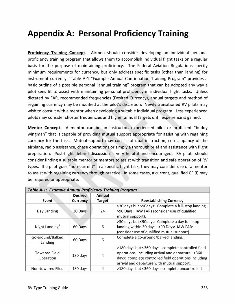
RV-Type Training Guide 358
Appendix A: Personal Proficiency Training
Proficiency Training Concept. Airmen should consider developing an individual personal
proficiency training program that allows them to accomplish individual flight tasks on a regular
basis for the purpose of maintaining proficiency. The Federal Aviation Regulations specify
minimum requirements for currency, but only address specific tasks (other than landing) for
instrument currency. Table A-1 “Example Annual Continuation Training Program” provides a
basic outline of a possible personal “annual training” program that can be adopted any way a
pilot sees fit to assist with maintaining personal proficiency in individual flight tasks. Unless
dictated by FAR, recommended frequencies (Desired Currency), annual targets and method of
regaining currency may be modified at the pilot’s discretion. Newly transitioned RV pilots may
wish to consult with a mentor when developing a suitable individual program. Less experienced
pilots may consider shorter frequencies and higher annual targets until experience is gained.
Mentor Concept. A mentor can be an instructor, experienced pilot or proficient “buddy
wingman” that is capable of providing mutual support appropriate for assisting with regaining
currency for the task. Mutual support may consist of dual instruction, co-occupancy of the
airplane, radio assistance, chase operations or simply a thorough brief and assistance with flight
preparation. Post-flight debrief discussion is very helpful and encouraged. RV pilots should
consider finding a suitable mentor or mentors to assist with transition and safe operation of RV
types. If a pilot goes “non-current” in a specific flight task, they may consider use of a mentor
to assist with regaining currency through practice. In some cases, a current, qualified CFI(I) may
be required or appropriate.
Table A-1: Example Annual Proficiency Training Program
Event Desired
Currency Annual Target Reestablishing Currency
Day Landing 30 Days 24 >30 days but ≤90days: Complete a full-stop landing. >90 Days: IAW FARs (consider use of qualified mutual support).
Night Landing1 60 Days 6 >30 days but ≤90days: Complete a day full-stop landing within 30 days. >90 Days: IAW FARs (consider use of qualified mutual support).
Go-around/Balked Landing
60 Days 6 Complete a go-around/balked landing.
Towered Field Operation
180 days 4
>180 days but ≤360 days: complete controlled field operations, including arrival and departure. >360 days: complete controlled field operations including arrival and departure with mutual support.
Non-towered Filed 180 days 4 >180 days but ≤360 days: complete uncontrolled
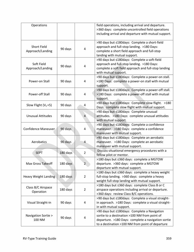
RV-Type Training Guide 359
Operations field operations, including arrival and departure. >360 days: complete uncontrolled field operations including arrival and departure with mutual support.
Short Field Approach/Landing
90 days 4
>90 days but ≤180days: Complete a short-field approach and full-stop landing. >180 Days: complete a short field approach and full-stop landing with mutual support.
Soft Field Approach/Landing
90 days 4
>90 days but ≤180days: Complete a soft-field approach and full-stop landing. >180 Days: complete a soft field approach and full-stop landing with mutual support.
Power-on Stall 90 days 4 >90 days but ≤180days: Complete a power-on stall. >180 Days: complete a power-on stall with mutual support.
Power-off Stall 90 days 4 >90 days but ≤180days: Complete a power-off stall. >180 Days: complete a power-off stall with mutual support.
Slow Flight (VS +5) 90 days 4 >90 days but ≤180days: Complete slow flight. >180 Days: complete slow flight with mutual support.
Unusual Attitudes 90 days 4 >90 days but ≤180days: Complete unusual attitudes. >180 Days: complete unusual attitudes with mutual support.
Confidence Maneuver 90 days 4 >90 days but ≤180days: Complete a confidence maneuver. >180 Days: complete a confidence maneuver with mutual support.
Aerobatics 90 days 4 >90 days but ≤180days: Complete an aerobatic maneuver. >180 Days: complete an aerobatic maneuver with mutual support.
SEPT 180 days 2 Discuss situational emergency procedures with a fellow pilot or mentor.
Max Gross Takeoff 180 days 2 >180 days but ≤360 days: complete a MGTOW departure. >360 days: complete a MGTOW departure with mutual support.
Heavy Weight Landing 180 days 2 >180 days but ≤360 days: complete a heavy weight full-stop landing. >360 days: complete a heavy weight full-stop landing with mutual support.
Class B/C Airspace Operation
180 days 2 >180 days but ≤360 days: complete Class B or C airspace operations including arrival or departure. >360 days: review Class B/C operations.
Visual Straight-in 90 days 4 >90 days but ≤180days: Complete a visual straight-in approach. >180 Days: complete a visual straight-in with mutual support.
Navigation Sortie > 100 NM
90 days 4
>90 days but ≤180days: Complete a Navigation sortie to a destination >100 NM from point of departure. >180 Days: complete a navigation sortie to a destination >100 NM from point of departure

RV-Type Training Guide 360
with mutual support.
Non-precision Instrument Approach2 45 days 6
>45 days but ≤360 days: complete a non-precision instrument approach. >360 days: complete an instrument competency check with a CFII.
Precision Instrument Approach2 45 days 6
>45 days but ≤360 days: complete a precision instrument approach. >360 days: complete an instrument competency check with a CFII.
Missed Approach2 180 days 2 >180 days but ≤360 days: Complete a missed approach. > 360 days complete a missed approach under the supervision of a CFII.
Course Intercept/Tracking2 180 days 2
>180 days but ≤360 days: complete course intercept/tracking. >360 days: complete an instrument competency check with a CFII.
Holding2 180 days 2 >180 days but ≤360 days: complete holding. >360 days: complete an instrument competency check with a CFII.
SFO/Emergency Landing
30 Days 12 >30 days but ≤180days: Complete a SFO pattern. >180 Days: complete a SFO pattern with mutual support.
Definitions
Event: Maneuver or flight element. Not all elements are applicable to all pilots. Desired Currency: Baseline provided may be modified at individual pilot discretion unless established by FAR. Annual Target: The number of times an event or maneuver should be flown in a 12-month (annual) period. Qualified: Valid pilot certificate, valid medical certificate, biennial flight review or flight check within the preceding 24 months; instrument rating required for IFR operations. Current: Minimum frequency required to perform an event or sortie safely. Proficient: Demonstrated ability to accomplish event safely and effectively, requires currency. Safe: Demonstrated ability to accomplish even safely, sufficient to reestablish currency. Experienced: 100 hours in type Inexperienced: Less than 100 hours in type Mutual Support: The appropriate level of assistance to practice and regain currency in a maneuver based on circumstances and judgment. This assistance could be provided by an instructor, mentor, flight lead or proficient fellow pilot. Instrument Competency Check: IAW 14 CFR Part 61. CFII required. “SFO”: “simulated flame out,” i.e., simulated engine-out emergency pattern.
Notes 1Required for night operations. Day landing currency does not update night landing currency for the purpose of FAR compliance, but a day landing within 30 days is desired prior to establishing night currency. 2Required for IFR operation.
RV-Type Training Guide 361
Appendix B: RV-4/6/7/8 Advanced Handling Briefing
The briefing guide in this section has been prepared to assist instructors preparing to practice
or teach RV-type advanced handling techniques or for qualified pilots familiar with RV-type
advanced handling techniques that are interested in a review prior to conducting personal
proficiency training. Specific transition briefing guides are included in Part 2 of this publication
for use with syllabus training flights.
This briefing is presented in a chronological, detailed “talking paper” format and is designed to
be presented in 45 minutes by a qualified instructor. It is aligned with information presented in
Parts 1-3 of this publication. A cross-section of confidence, advanced handling maneuvers and
exercises is presented in this briefing. Not all maneuvers or exercises may be appropriate for all
flights or conditions and the briefing should be modified accordingly. Not all maneuvers or
exercises included in Parts 1-3 of this publication are included in this briefing guide. All
maneuvers are designed for positive G.
Instructor Briefing Considerations
An effective briefing should be custom-tailored as circumstances require. One of the most
important considerations is to keep the upgrading pilot engaged during the briefing. Effective
use of questioning is a good way to do this--a briefing should never be “one way.” There is a
Warning
Information in this briefing guide is not intended as a substitute for suitable and appropriate flight training. It has been designed for instructors and/or pilots current and qualified in the appropriate RV-type that are familiar with and qualified to perform aerobatic flight.
Van’s Aircraft aerobatic design limits are included in this briefing guide and must be adhered to for the conduct of aerobatic operations. Not all RV-types are capable of being operated in a “dual instruction” configuration for the purpose of aerobatic instruction due to weight and balance limitations. Weight and balance data and Operating Limitations for the aircraft operated must be utilized to determine suitability.

RV-Type Training Guide 362
limit to any pilot’s ability to sit through a briefing and absorb information—if that limit is
exceeded, the briefing becomes counter-productive. As a general rule, briefing time should not
exceed 45 minutes. If the upgrading pilot is actively engaged in the briefing and participating by
asking or answering questions, the total briefing time may increase to approximately 60
minutes. Flying aerobatic RV-types throughout the envelope is serious business and fun at the
same time—be sure to impart that when briefing, teaching or mentoring.
One of the most important considerations is to be clear and correct (the law of primacy of
learning applies) when briefing. New skills and knowledge must be presented correctly the first
time. A mix of graphic, video aids or model demonstrations can greatly enhance a verbal
description of the task--pictures truly are worth a thousand words. One briefed technique for
task accomplishment is generally sufficient—attempt to give the upgrading pilot something to
“hang their hat on.” An alternative technique can be offered if it becomes clear that the
upgrading pilot does not understand what is being briefed or, more likely, may be offered real-
time in the cockpit if the upgrading pilot is not having success accomplishing a task with the
technique initially presented during the briefing.
Although not specifically contained in the briefing guide, a brief re-cap followed by an
opportunity for the upgrading pilot to ask any additional questions should be provided at the
end of every briefing.
This guide has been prepared in a chronological flow—it covers the flight from start to finish, in
order. If the upgrading pilot is already proficient in basic RV-type operations, it may be more
effective to re-arrange the briefing order. Start with “admin” (i.e., getting to the area and RTB),
special subjects, and academic review (not to exceed 5-10 minutes), then cover the “meat” of
the flight: area work. This alternative briefing flow utilizes the basic learning law of recency to
maximize retention opportunity for the upgrading pilot regarding area work described.
Academic briefings presented in Part 2 or techniques and handling characteristic information
presented in Part 3 of this document can provide additional source material, if desired.
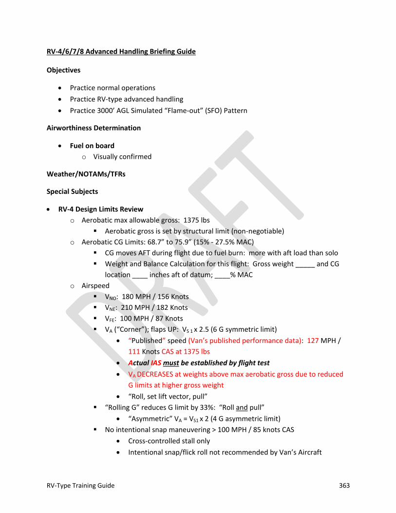
RV-Type Training Guide 363
RV-4/6/7/8 Advanced Handling Briefing Guide
Objectives
Practice normal operations
Practice RV-type advanced handling
Practice 3000’ AGL Simulated “Flame-out” (SFO) Pattern
Airworthiness Determination
Fuel on board
o Visually confirmed
Weather/NOTAMs/TFRs
Special Subjects
RV-4 Design Limits Review
o Aerobatic max allowable gross: 1375 lbs
Aerobatic gross is set by structural limit (non-negotiable)
o Aerobatic CG Limits: 68.7” to 75.9” (15% - 27.5% MAC)
CG moves AFT during flight due to fuel burn: more with aft load than solo
Weight and Balance Calculation for this flight: Gross weight _____ and CG
location ____ inches aft of datum; ____% MAC
o Airspeed
VNO: 180 MPH / 156 Knots
VNE: 210 MPH / 182 Knots
VFE: 100 MPH / 87 Knots
VA (“Corner”); flaps UP: VS 1 x 2.5 (6 G symmetric limit)
“Published” speed (Van’s published performance data): 127 MPH /
111 Knots CAS at 1375 lbs
Actual IAS must be established by flight test
VA DECREASES at weights above max aerobatic gross due to reduced
G limits at higher gross weight
“Roll, set lift vector, pull”
“Rolling G” reduces G limit by 33%: “Roll and pull”
“Asymmetric” VA = VS1 x 2 (4 G asymmetric limit)
No intentional snap maneuvering > 100 MPH / 85 knots CAS
Cross-controlled stall only
Intentional snap/flick roll not recommended by Van’s Aircraft
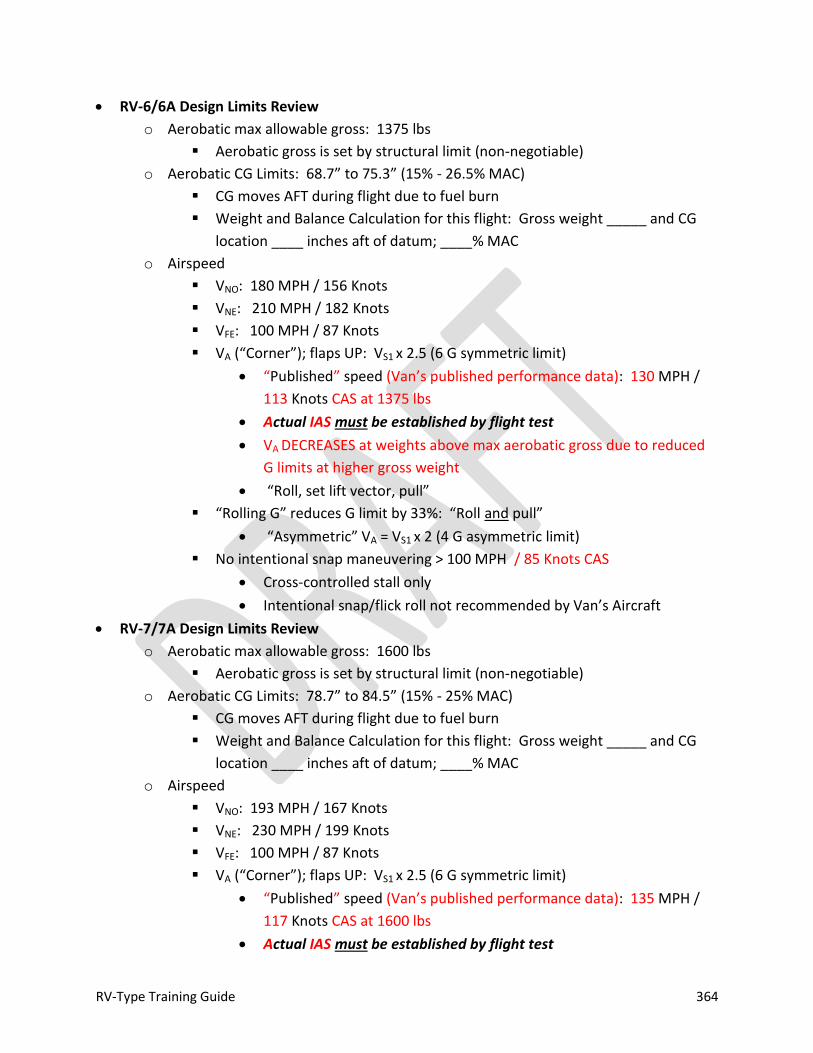
RV-Type Training Guide 364
RV-6/6A Design Limits Review
o Aerobatic max allowable gross: 1375 lbs
Aerobatic gross is set by structural limit (non-negotiable)
o Aerobatic CG Limits: 68.7” to 75.3” (15% - 26.5% MAC)
CG moves AFT during flight due to fuel burn
Weight and Balance Calculation for this flight: Gross weight _____ and CG
location ____ inches aft of datum; ____% MAC
o Airspeed
VNO: 180 MPH / 156 Knots
VNE: 210 MPH / 182 Knots
VFE: 100 MPH / 87 Knots
VA (“Corner”); flaps UP: VS1 x 2.5 (6 G symmetric limit)
“Published” speed (Van’s published performance data): 130 MPH /
113 Knots CAS at 1375 lbs
Actual IAS must be established by flight test
VA DECREASES at weights above max aerobatic gross due to reduced
G limits at higher gross weight
“Roll, set lift vector, pull”
“Rolling G” reduces G limit by 33%: “Roll and pull”
“Asymmetric” VA = VS1 x 2 (4 G asymmetric limit)
No intentional snap maneuvering > 100 MPH / 85 Knots CAS
Cross-controlled stall only
Intentional snap/flick roll not recommended by Van’s Aircraft
RV-7/7A Design Limits Review
o Aerobatic max allowable gross: 1600 lbs
Aerobatic gross is set by structural limit (non-negotiable)
o Aerobatic CG Limits: 78.7” to 84.5” (15% - 25% MAC)
CG moves AFT during flight due to fuel burn
Weight and Balance Calculation for this flight: Gross weight _____ and CG
location ____ inches aft of datum; ____% MAC
o Airspeed
VNO: 193 MPH / 167 Knots
VNE: 230 MPH / 199 Knots
VFE: 100 MPH / 87 Knots
VA (“Corner”); flaps UP: VS1 x 2.5 (6 G symmetric limit)
“Published” speed (Van’s published performance data): 135 MPH /
117 Knots CAS at 1600 lbs
Actual IAS must be established by flight test
RV-Type Training Guide 365
VA DECREASES at weights above max aerobatic gross due to reduced
G limits at higher gross weight
“Roll, set lift vector, pull”
“Rolling G” reduces G limit by 33%: “Roll and pull”
“Asymmetric” VA = VS1 x 2 (4 G asymmetric limit)
No intentional snap maneuvering > 100 MPH / 85 Knots CAS
Cross-controlled stall only
Intentional snap/flick roll not recommended by Van’s Aircraft
RV-8/8A Design Limits Review (Dash One Wing)
o Aerobatic max allowable gross: 1600 lbs
Aerobatic gross is set by structural limit (non-negotiable)
Non Dash One Wing (kits shipped prior to Jan 2001): 1550 lbs aerobatic
gross weight limit
o Aerobatic CG Limits: 78.7” to 85.3” (15% - 26.5% MAC)
CG moves AFT during flight due to fuel burn
Weight and Balance Calculation for this flight: Gross weight _____ and CG
location ____ inches aft of datum; ____% MAC
o Airspeed
VNO: 193 MPH / 167 Knots
VNE: 230 MPH / 199 Knots
VFE: 100 MPH / 87 Knots
VA (“Corner”); flaps UP: VS1 x 2.5 (6 G symmetric limit)
“Published” speed (Van’s published performance data): 135 MPH /
117 Knots CAS at 1600 lbs
Actual IAS must be established by flight test
VA DECREASES at weights above max aerobatic gross due to reduced
G limits at higher gross weight
“Roll, set lift vector, pull”
“Rolling G” reduces G limit by 33%: “Roll and pull”
“Asymmetric” VA = VS1 x 2 (4 G asymmetric limit)
No intentional snap maneuvering > 100 MPH / 85 Knots CAS
Cross-controlled stall only
Intentional snap/flick roll not recommended by Van’s Aircraft
“G-allowable” = G limits (4 or 6)
“G-available” = aerodynamic G the airplane is capable of generating based on dynamic
pressure (airspeed)
o ABOVE MANEUVERING SPEED (“CORNER VELOCITY”); G-AVAILABLE EXCEEDS G-
ALLOWABLE

RV-Type Training Guide 366
o @90 MPH 2.7 G’s available
o @110 MPH 4.0 G’s available
o @130 MPH 5.6 G’s available
o @VA 6.0 G’s available (approximately 135 MPH / 117 Knots)
o @VNO (top of the green arc) 10.7 G’s available
o @VNE (red line, TAS) 14.6 G’s available
Absolute G limit 9.0 symmetrical (flaps retracted); catastrophic failure can
occur at G loads in excess of 9.0 if sustained more than 3 seconds
No construction errors or fatigue damage
Fatigue damage in metal airplanes is cumulative over time; structure
has a “memory”; history of over-G can cause catastrophic failure at g
loads less than design limits
Decreased pitch stability
o High power / high pitch angle
Terminology
o “Energy” (EM) ≈ altitude + airspeed + specific power (PS)
o “Velocity Vector” = where the airplane is going, but not necessarily pointing (flight
patch indicator)
o “Lift Vector” = direction in which lift is acting, roughly perpendicular to the wings or
the direction the pilot’s head is pointing when sitting upright
o “Boresight” = where the airplane’s nose is pointing
o “ON SPEED” = L/DMAX ≈ VREF (1.3 to 1.4 VS)
“Unload for Control” Concept
o Unless planned, unload for control (release or decrease back stick pressure as
required) at first sign of loss of control (“departure”): buffet, wing rock/drop, nose
slice or nose rise (stick lightening)
Bail out of maneuver before things get worse…
Terminate maneuvering and recover to level flight by flying to the
nearest horizon
Airplane can’t stall at zero G; VS significantly reduced at “low G” (0 to ½
positive G)
o “Idlize and neutralize”
Power to Idle
Neutralize rudder input
Center stick laterally
Smooth unload to 0 to ½ G condition
Seat of the pants cues: heels light, items might start to float
RV-Type Training Guide 367
Carb’d engine? Reduction in RPM / engine noise = effective forward
limit (unless control is in doubt, then establish zero G condition and
allow engine to stop, if required)
Anticipate ballistic condition / recovery: speed increasing past 100 MPH / 90
Knots
Nose high ROT: degrees nose up at unload = degrees nose down
during recovery
Confidence maneuvers are designed to practice low G (0 – ½), low airspeed
handling
Out-of-Control (“Departure” from controlled flight)
o Check altimeter: Recover / Bail-out?
Decent rate in a developed spin is 7000-9000 FPM
Recovery from a developed upright spin (including dive recovery) requires 1
½ turns and 1500 feet of altitude
Above maneuvering floor; time available
Below minimum out-of-control bail-out altitude; might as well work
on it!
o Power IDLE
o Controls NEUTRAL
Be PATIENT: immediate aircraft response to neutral controls may not be
apparent
o Rudder OPPOSITE YAW (IF REQUIRED)
Sight down nose; needle (if equipped)
o Elevators PAST NEUTRAL (IF REQUIRED)
Forward stick if upright, back stick if inverted
o Unusual Attitude RECOVER
Aircraft is no longer out of control if unloaded (0 to ½ G condition) and
airspeed is increasing past 100 MPH / 90 Knots
Dive recovery: smooth application of G and power to control airspeed
IDLE if speed > VA
o Fixed pitch prop? Low drag = be ready!
ANTICIPATE ACCELERATION; apply back stick as required during initial
phase to prevent over-speed: DON’T HESITATE TO APPLY SUFFICIENT
G (short of limit loads) TO ARREST/CONTROL RATE OF ACCELERATION
o Be alert for buffet; nose stops tracking; nose slice; wing
drop—these are positive stall indications
If unintentional over-speed (red line) occurs, do not panic; continue
smooth pull with throttle IDLE
RV-Type Training Guide 368
Avoid secondary stall
Bailout
o Parachute requirement: More than one on-board; Pitch > 30o and/or Roll > 60o
“Aerobatic” definition: “any intentional maneuver involving an abrupt
change in and aircraft’s attitude, an abnormal attitude, or abnormal
acceleration, not necessary for normal flight”
RV-4 canopy is jettisoned by opening it in flight; once the pins are released,
air load will pull the canopy off of the airframe
The hinge on the right side will tear away from the fuselage
Clamshell canopies on side-by-side types may be fitted with jettison handle
Sliding canopies may or may not be equipped for jettison
As a curved surface, all canopies generate lift; depending on track
configuration, in-flight opening and/or jettison may be difficult
Air loads will be reduced at lower airspeed
o Minimum Bailout Altitude
Practice area MSL surface elevation: ___________
Add 2500 feet (round answer up): ___________
2500 feet AGL is TR limit assuming a “standard” 5-10 second egress
sequence; determine individual egress time and increase altitude, as
required
See Determining Minimum Out-of-Control Bailout Altitude
Air Start
o Handling error (sustained low G) can cause fuel starvation if aircraft not equipped
with inverted systems
One reason SMOOTH, deliberate pitch control is required; never “slam” the
stick—airplane takes time to respond to inputs
Be alert to noise cues: engine as G meter
o Engine may stop: don’t adjust engine controls
o Lightweight, fixed-pitch prop? Prop will likely stop if low G (zero or less) and low
airspeed condition is achieved (generally VS or less)
o Maintain aircraft control; apply standard unload for control concepts; if prop is
windmilling, engine will re-start; if prop is stopped, wait until airspeed is increasing
and hit the starter switch
A windmill restart can be conducted, but requires considerable airspeed
(altitude) to start turning a stopped propeller
Engine and Power Effects
o Pay attention to the ball—do what it takes to keep the ball centered

RV-Type Training Guide 369
“Step on the ball” Unless intentionally slipping or skidding, always fly in a
coordinated manner
o High airspeed: generally left rudder
o Low airspeed: IT DEPENDS
High power—right rudder
Low power—in the direction of roll
o Use to your advantage: Roll left when you’re learning!
Training Rules
Discernable horizon; standard cloud clearance limits; 3SM visibility minimum
o 1000 above / 500 below / 2000 horizontal
o Make allowance for maneuvering room required
Loaded within Van’s specified design limits
Phase I tested maneuvers: annotated in log book or operating limitations
Area Selection (FAR requirements):
o Not over congested area/open air assembly of persons
o Not within lateral boundaries of Class B, C, D or E Airspace designated for an
airport
o Not within 4 NM of the centerline of federal airway
o 1500’ AGL minimum altitude
Stability Check complete / acceptable
Maximum fuel imbalance: 6 gallons (36 lbs; approximately 42 minutes of fuel burn)
Pre-maneuver flow complete prior to each maneuver or sequence of maneuvers
o Loose items stowed / harness secure / fuel balanced / boost pump on
o Area clear
Planned spins: 1 ½ turn or less
Floor: 3000’ AGL
o ______________MSL
Round answer up to something easy to read on the altimeter
Minimum “admin” airspeed: 80 MPH / 70 CAS (everything except accept stalls / post-
stall maneuvering / slow flight / confidence maneuvers and advanced handling / takeoff
and landing)
Smooth control application
Maximum symmetric G: 6
Maximum asymmetric (rolling) G: 4
Target maneuvering G: 4
o Sufficient airspeed available

RV-Type Training Guide 370
Minimum G: 0
o Negative G excursion: knock-it-off if oil loss is suspected, land as soon as
practical and check servicing
Monitor appropriate ATC frequency
Normal Ground Ops
Start IAW Checklist
Lean aggressively after start and during ground ops
o Warm-up ROT 200o CHT (if equipped) prior to taxi
o Brake check
Taxi speed control: throttle primary / proper brake use / maximum speeds
o 15 knots GS pavement (5-10 turning) / “jogging speed” 5-7 kts unpaved
o Flight controls: stick aft to 15 knot tailwind / “dive away” or “turn into”
o S-turns generally not necessary at design eye height
o Task management: stop as required / avoid “head’s down” in motion
Be aware of prop blast at all times
Run-up: mixture use / EGT rise on one ignition system / be expeditious
o Fouled plugs not likely with proper leaning (on ground and airborne)
o Prop blast considerations over-ride pointing into the wind
o Canopy secure and checked PRIOR to run-up
o Bad check = rough engine or falling/erratic EGT (if equipped) on any cylinder
If equipped, watch monitor and tach
o Engine sufficiently warm for takeoff? Lycoming answer: when power can be
advanced without hesitation; alternatively oil 85oF or warmer and/or warmest
CHT 300o (if equipped) or warmer.
Normal Take-off
Before takeoff flow / checklist complete
o Mixture (if lean) SET
Full rich below 3000’ density altitude
o Note hobbs / tach and hack stopwatch
o Flaps 20 / trim set
Neutral for solo / more nose down if CG aft (passenger / baggage)
o Final clear
o Note wind: anticipate cross-wind steering requirement
Smooth application of power: don’t jam throttle
o Technique

RV-Type Training Guide 371
“2 Count”
Pause at approximately 50%: check gauges (oil pressure / airspeed off
the peg at approximately 25)
“2 Count” to WOT
o Full power: check MP (inches approximately = altimeter setting) + RPM
Fixed pitch: typically 2100-2200 RPM
Constant speed: typically red line RPM
Anticipate need for right rudder: rotate and establish crab as necessary to track
centerline
Flaps up NLT VFE: Don’t allow aircraft to “settle” during flap retraction
Cruise Climb
Wide speed band for climb performance: set 120-140 MPH / 105-125 Knots CAS
o Monitor CHT: ≤ 400oF (desired) max; adjust speed as required for cooling
WOT climb
Note EGT (if equipped) when climb condition established
Passing 3000’ density altitude, slowly lean to EGT noted at start of climb (best power
condition)
Level Off
Trim
Accelerate to desired / anticipated cruise speed (TAS or CAS)
Set cruise power
o “Rule of 48” (normally aspirated below approximately 10,000 feet)
MP (inches) + RPM/100 ≈ power setting
If total 48, then ≈ 75%
If total 45, then ≈ 65%
If total 42, then ≈ 55%
Interpolate as desired
o Engine power chart, if available over-rides “Rule of 48”
Mixture: already best power if leaning started in climb; else “big pull” to target best
power EGT; fine adjustment to best economy (LOP), as desired
o LOP
As desired if injected / balanced
25o LOP target / rough engine if carbureted
o Can’t hurt engine by leaning at power settings less than 60-65%
RV-Type Training Guide 372
Use same technique for each intermediate level-off as required; adjust mixture as
necessary but be sure to advance for increased power required for climb
For handling sortie, level-off at maneuvering floor (3000’ AGL recommended) + 2000 to
3000 feet as desired
o Set appropriate hemispheric cruise altitude enroute to practice area: “odd men
fly east”
Stability Check
Stability check is performed to determine if aircraft will exhibit normal (non-divergent)
stability during maneuvering flight; confirms weight and balance and helps calibrate
pilot’s butt; should initially be performed from straight and level flight until proficiency
is gained; DO NOT CONDUCT MANEUVERING FLIGHT IF STABILITY CHECK IS NOT
SATISFACTORY
Review/emphasize weight and balance condition for flight
o Stick force gradient and static margin function of CG/AC relationship (% MAC)
Fuel balanced < 6 gallons (36 lbs) differential (approximately 42 minutes on stop
watch)
Pitch Check (Positive stability required)
o Trim; note stick position
o Smooth pull to -10 to 15 MPH / knots of trim speed
o Ease stick forward to trim position
o Note pitch response
o Bad check: nose continues to pitch up or oscillate
Roll Check (Neutral stability required; may exhibit positive stability)
o Trim (if equipped)
o Roll 45-60o bank
o Neutralize aileron input
o Note roll response
o Bad check: roll continues to steepen
Yaw Check (Positive stability required)
o Note ball; trim (if equipped)
o Smoothly induce yaw input
o Remove feet from pedals
o Note yaw response (fish tail + Dutch roll is normal)
o Bad check: yaw oscillations don’t damp after 4-6 excursions
Basic Maneuvering Flight Considerations
RV-Type Training Guide 373
Adjust mixture and throttle as required—make sure that mixture is always advanced
ahead of throttle
o Full rich if in doubt
Accomplish “pre-maneuver” flow; make sure you and the airplane are ready for all-
attitude maneuvering
o Loose items stowed / harness secure / fuel balanced / aux pump on / area clear
o Accomplish this flow before each maneuver or set of maneuvers during practice
o Foot stomper: Keep your scan going; instruments as required to assess energy
and outside!
Fuel venting is normal during maneuvering flight; especially with a full tank
o May notice fuel odor in cockpit
o Fuel system/vents built to plans:
Fuel tends to vent on belly during low G maneuvering (0 – ½ cockpit G)
Fuel tends to vent over wing root(s) during post-stall (spin) maneuvering
Ensure harness (lap belt) is TIGHT and loose items are secure
o Harness may tend to loosen during maneuvering due to clothing and seat
cushion compression—re-check and tighten as necessary between maneuvers
Maintain navigational SA (ground references / moving map display) and CLEAR
throughout maneuver sequence; monitor appropriate ATC approach or departure
frequency (if appropriate)
o Be alert for ATC call if you are the “bogey”
Look for smooth air: morning, above LCL (lifted condensation level, i.e., clouds), etc.
Maneuvering at altitude? Tradeoff between finding smooth air and hitting airspeed
limits: be aware of TAS
o VNO effective maneuvering limit; know VA
o Beware VNE (redline): TAS, not CAS/IAS
Determining Maneuver Speed / Corner Velocity
Definition: Speed below which you can move a single flight control, one time, to full
deflection for one axis of airplane rotation only (pitch, roll or yaw), in smooth air,
without risk of damage to the airplane.
o Below maneuvering speed, airplane will stall before hitting structural limits
o Flaps UP
o Minimum turn radius, maximum turn rate occurs at this speed
o Generally SLOWER than most folks realize
Varies by gross weight / stall speed; need to know SYMMETRIC and ASYMMETRIC
speeds
o “Straight pull” vs “rolling G”
RV-Type Training Guide 374
o Asymmetric G limits not specified by Van’s Aircraft; assuming 33% reduction in
G-allowable
o Formula: Stall Speed x √G-allowable = maneuvering speed
Determine VS1: power-off flaps-up stall speed; use standard 1 MPH / knot per second
deceleration; note IAS at which airplane stalls
Determine VA
o Stall x 2.5 = symmetric VA
o Stall x 2.0 = asymmetric VA
Write speeds down on line-up card
Above maneuvering speed; a handling error can result in an over-G condition
“Unload, roll, set, pull” concept
G Warm-up
Energy losing; plan to lose 500-1000’ for 180o of turn; start at Floor +1000’
Need to strain PRIOR to G-onset; can’t “catch up”
o Knock-it-off if: ANY reduction in visual acuity or ability to discern color
Establish slow cruise condition: VA (“corner velocity”) + 20
o Entry speed can be increased as proficiency is gained; higher speed requires less
altitude but more prone to handling error
3-4 G “Break turn”
o Remind yourself to begin anti-G strain
o Unload
o Roll (set 90-110o bank)
o Smooth pull to 3-4 G’s
Increase power to WOT during G onset
Maintain for 180o of turn or reverse after 90o, as desired
o Adjust lift vector (“windshield wiper”) as required to maintain corner (VA) and
desired G throughout
Note buffet cues, if any
Confidence Maneuvers
Confidence maneuvers are designed to increase pilot confidence and teach low AOA
handling and recovery techniques. They provide a foundation for advanced handling
maneuvers and all-attitude upset recovery.
Steep Turns
o Energy Neutral → Losing, Floor +500’ min entry
RV-Type Training Guide 375
o Two techniques: cruise power (energy bleeding turn) or WOT (energy sustaining
turn)
o Cruise Power
Ground reference points can assist with orientation, else consider use of
cardinal heading to start
Power: set for cruise
Bank: 45-70o
Visual cue: cowl/cowl fasteners relative to horizon; varies by
sitting height; different for left vs. right turn
Back pressure as required
1.4 G’s at 45o
2.0 G’s at 60o
3.0 G’s at 70o
Airspeed will bleed at stabilize after bank is established
Coordinate
Anticipate roll-out: NLT desired heading -10o
Remove back pressure
o WOT
Same as cruise power except increase throttle to wide open when rolling
into the turn
Speed should stabilize at or slightly below entry speed (some bleed if 70o
of bank used)
Lazy 8 (Energy Neutral → Gaining, Floor min entry)
o Not the Lazy 8 described in the FAA Flight Training Handbook or Practical Test
Standards
Maneuver is designed to utilize the entire speed band from stall (or less)
to VNO, G loads from 0 to +2.5, and pitch and bank angles up to 90o
Optimum RV-type handling warm up maneuver; intensity can be
increased as proficiency is gained
Excess power is available: Power settings at/above 65% will cause
altitude gain each leaf
o Select a ground reference: straight line of some type optimum; cross-
perpendicular to start maneuvering
Cardinal heading can help
o Set cruise power condition: 60-65%
o Smooth pull into vertical as you begin to roll
Coordinate!
RV-Type Training Guide 376
Left roll/pull/turn easier than right due to engine power effects;
anticipate
o Pitch/Bank ≈ 45o at 45o turn point
+45o pitch ≈ heels on the horizon
o Float pitch as required to get airspeed as low as desired
Unload
May notice fuel odor in cockpit if tanks are venting
o Rudder as required to keep nose tracking
Check ball
o Pitch as desired for airspeed / Bank 90o as nose slices through horizon
Check airspeed
With <1G, speed can be lower than stall
Left turn easier than right turn: necessary to carry more airspeed
over the top for a right turn
o As nose drops through horizon; begin pull and roll
Look outside: figure out where you want to point when you “bottom
out” and adjust roll rate to get there
o At 45o point, pitch should be -30 to -45o and bank angle should be decreasing
through 45o
o Exact pitch isn’t important: what IS important is controlling airspeed and
altitude during bottom leaf—airspeed (less than VNO) always takes priority over
altitude
Accept any climb at the bottom to keep airspeed under control
Altitude? Be aware of TAS
o Complete as many “leaves” as desired
AOA (Ballistic) Recovery
o Energy Neutral → Loosing, Floor +1000’ min entry
o Cruise condition
o Aileron and rudder neutral
o Smooth pull: 45-60o nose up (heels on the horizon +)
o Airspeed approaching 100: smooth unload 0 to ½ G, power IDLE
“Heels light”
Carb? Keep engine running by maintaining sufficient positive G
o Maintain low G (0 to ½) condition until airspeed increasing above 100 MPH / 90
Knots
Degrees up = degrees down
o Recover
o As proficiency gained, perform maneuver from 30-60o bank

RV-Type Training Guide 377
Inverted Recovery
o Energy Neutral → Loosing, Floor +1000’ min entry
o Similar to AOA Recovery, but flown inverted
o Speed VNO or slightly less
o Smooth pull: WOT, 45-60o nose up (heels on the horizon +)
o Airspeed approaching 100: smooth unload to 0 to ½ G, power IDLE
“Heels Light”
Carb? Keep engine running
o Roll to inverted (Established NLT 80 MPH / 70 Knots)
o Maintain 0 – ½ G condition
Stick as required to maintain G; push may be required but don’t go
negative
o Unloaded roll to upright as speed passes 100 MPH / 90 Knots
o Recover
Degrees up = degrees down
Low AOA Aileron Roll
o Energy Neutral → Loosing, Floor +1000’ min entry
o Similar to Inverted Recovery, but steady unloaded roll
o Speed VNO or slightly less
o Smooth pull: WOT, 45-60o nose up (heels on the horizon +)
o Airspeed approaching 100: smooth unload to 0 to ½ G, power IDLE, ROLL
Stick as required during roll to maintain 0 – ½ G
“Heels Light”
Carb? Keep engine running
o Recover as airspeed passes 100 MPH / 90 Knots
Degrees up = degrees down
o Initially, roll left; right roll as proficiency is gained
Stalls
NACA 23013.5 Airfoil: Critical AOA 14-15o
o Standard design (no stall strips or VG’s fitted): normal stall characteristics;
limited buffet warning (only 1-2 MPH prior to stall at 1 G); stall progresses from
root outboard—ailerons remain effective; but RUDDER is primary yaw control
o Stall cues
Buffet (proportional to G load: higher G—slightly more buffet)
Nose rise (stick getting light)
Nose slice (uncommanded yaw you pick up by sighting down the nose)
Wing drop (can be significant and abrupt)

RV-Type Training Guide 378
Aerodynamic cues can be missed with aggressive G / AOA onset rate
o Engine power effects increase as airspeed decreases
Keep ball in cross-check / scan
If (right) aileron is used pre-stall to control engine power effects; (left)
wing drop is likely post-stall (can be significant)
o Recovery is prompt when AOA is reduced
“Unload for control;” primary stall recovery procedure is to REDUCE AOA;
if sufficient altitude is available, adding power is not necessary to recover
Type of gear fairings affect post-stall handling characteristics
o Fairings provide vertical aerodynamic surface AHEAD of the aerodynamic center
o Larger chord fairings (e.g., Harmon Rocket) are more destabilizing than Van’s
supplied fairings
o Type/configuration of fairings can affect aerodynamic buffeting of the horizontal
stabilizer
Power-off
o Energy Losing, Floor +500’ min entry
o Flaps Up
o Flaps Down
Note flaps down speed, multiply by 1.4 to determine VREF for landing if
not equipped with AOA indicator
o Use 1 MPH / Knot per second decel rate
o If trimming stop NLT computed VREF / ON SPEED (approach speed) for current
configuration
o Keep an eye on the ball; center it up with your feet
Some roll prior to stall is normal (engine power effects)
Eye’s out only? If you counter left rolling tendency with right aileron; left
wing will drop post stall
Ball centered? Airplane will stall straight ahead
o Recovery: relax back pressure (reduce AOA)
Airplane will recover promptly
o Add power, if desired
o Can vary flap settings and bank angle at stall
Full flaps and 20-45o bank simulated base turn for “approach stall”
Power-on
o Energy Neutral → Losing, Floor +500’min entry
o Power: 50% to WOT
RV-Type Training Guide 379
Nose up attitude will vary with power setting and entry technique; low
power loading (HP/lb) results in significant nose-up at high power
settings
Anticipate need for significant right rudder at low airspeed / high
power settings
Build-up approach: increase power setting / pitch angle as
proficiency is gained
If zoom into stall isn’t desired; allow airplane to slow and increase
pitch and power simultaneously
o If trimming stop NLT computed VREF / ON SPEED (approach speed) for current
configuration
Pitch stability begins to break down at high pitch / high power settings
Stick gets lighter—less need for trim (anticipate)
o Keep an eye on the ball; center it up with your feet
Do what it takes; but anticipate need for right rudder
Significant at high power settings
o Recovery: relax back pressure (reduce AOA)
Airplane will recover promptly
Accelerated Stall
o Airplane can stall at any airspeed and any attitude if 15o α is exceeded
αcrit is constant: not affected by gross weight
o Energy Losing, Floor +500’ min entry
o Power: Cruise to WOT
o Flaps up only
o 2 G stall will occur ≈ 130% VS
About 80 MPH / 70 Knots ; normal pattern speed
o Establish 150 MPH / 130 Knots
o Roll to 60o + bank
o Smoothly and aggressively apply G
2 G per second onset to 3-4 G’s (≈ 2-3 second pull)
o Stall cues
Buffet
Nose rise (stick getting light)
Nose stops tracking across horizon
Wing drop (can be significant and abrupt)
Aerodynamic cues can be missed with aggressive G onset rate; wing drop
likely first cue
RV-Type Training Guide 380
o Slow pull? Aircraft will bleed energy (airspeed); may develop high sink rate in lieu
of stall
o Recover
Reduce AOA
Adjust lift vector, as required
Reduce power if having difficulty maintaining yaw control
Deep Stall
o Energy Losing, Floor +2000’ min entry
o Power: IDLE (mitigate engine power effects)
o Flaps up only
o If trimming stop NLT computed VREF / ON SPEED (approach speed) for current
configuration
o Two-hand technique: assists with maintaining stick centered laterally
Tendency with one hand is back and right
“Zipper / Button” pull: aim at your buttons to keep it straight
o Control rigging considerations
Van’s specified elevator limits
Design limits +30o up / -25o down
Minimum limit +25o up / -20o down
Variation can effect individual aircraft handling characteristics
o Rudder remains effective post-stall
Precise heading control not practical
Be alert for nose slice
Significant wing rock (drop) likely
Make corrections similar to directional control on the ground—get the
required rudder IN then OUT (neutralize); sustained rudder input post-
stall will force auto-rotation (spin)
Constant/needless rudder inputs can aggravate the post-stall
situation ad make it difficult to determine actual aircraft
performance—neutralize or pause to assess input effect
o Nose will “bob” with CG in forward 2/3 of aerobatic envelope with full aft stick
Spin resistant in this part of the envelope
o Post-stall directional stability begins to break down at the back of the envelope
Assume no margin at aft limits: be alert for uncommanded yaw
o Significant buffet normal in sustained deep stall
o Check VVI: high descent rate
o Recover
Reduce AOA
RV-Type Training Guide 381
Add power, if desired
Cross-controlled Stall
o Energy Losing, Floor +1500’ min entry
o Flaps up only
o These maneuvers will result in a low energy (below asymmetric VA) snap roll
“departure”
o Maneuvers designed to demonstrate what happens if coordinated flight isn’t
maintained and critical AOA is unintentionally exceed during the base turn
o Slip
Can be simple stall or rolling departure, over-the-top (must be forced)
Plenty of aerodynamic warning of departure/auto-rotation: High AOA
rudder roll prior to stall
Simulating slipping base turn to final
Power IDLE
At 80 MPH CAS (70 Knots), start base turn
Initiate a slip to the “inside” of the turn
Left turn, left slip: (“inside”) left aileron + right (“outside”) rudder
Right turn, right slip: right aileron + left rudder
Increase AOA to stall
Generally, airplane will simply stall in the slipping turn without
rolling over-the-top (in the direction in which rudder is applied)
If forced, airplane may rudder roll (in the direction in which
rudder is applied) due to roll-coupling effects as AOA increases
past approximately 10o
o This slow roll is aerodynamic warning of impending
departure
o As AOA passes 14-15o, slow rudder roll will transition to
snap roll in direction in which rudder is applied
Recovery
Depends on whether aircraft departed or just stalled:
o Just stalled (no/little rudder roll encountered prior to stall)
Reduce AOA
Slip input can be maintained throughout
stall/recovery
o Rudder roll occurred prior to stall/snap-roll:
Neutralize lateral stick and rudder
Reduce AOA

RV-Type Training Guide 382
Quickest recovery to wing’s level is to “snap” back
to upright; otherwise unusual attitude recovery
may be necessary
If in a nose-low, unusual attitude close to the
ground PULLING may not be appropriate control
input: do what it takes not to hit the ground
Note altitude lost and compare to typical base turn
AGL altitudes
Remember rudder roll picture: if rudder roll opposite aileron is
encountered, you need to reduce AOA when slipping
o “Skid”
Rapid rolling departure (snap roll) in direction rudder deflected when
airplane stalls
Little or no aerodynamic warning
Simulating over-shooting base to final turn
Power IDLE
At 80 MPH CAS (70 Knots), start base turn
Initiate a skid to the “inside” of the turn
Left turn, left rudder
Right turn, right rudder
Counter rudder induced bank with opposite aileron; allow nose to
“skid” in desired direction of turn with wings remaining relatively
level
Increase back pressure and allow airspeed to decrease
As AOA passes 14-15o, airplane will rapidly snap “underneath” (in
direction in which rudder is applied)
Little or no aerodynamic warning
Recovery
Neutralize lateral stick and rudder
Reduce AOA
Fastest recovery is to “snap” back to upright; otherwise unusual
attitude recovery may be necessary
o If in a nose-low, unusual attitude close to the ground
PULLING may not be appropriate control input: do what
it takes not to hit the ground
Note altitude lost and compare to typical base turn AGL altitudes

RV-Type Training Guide 383
Remember lack of aerodynamic cues; if you do over-shoot final—
let the overshoot happen, if you can’t correct using coordinated
flight, then go-around
“All Attitude” stall (Nose High Visual Unusual Attitude Recovery)
o Energy Neutral → Losing, Floor +500’ min entry
o Flaps up only
o Pitch limit 70-80o to avoid unintentional tail slide
o “Unload for Control” techniques apply
Nose up = nose down; be patient
0 to ½ G; maintain until aircraft is unloaded and airspeed is increasing
past 100 MPH / 90 Knots
Unloaded roll to 90o bank is OK to assist with recovery
Maintain bank angle until nose hits the horizon and airspeed is
increasing; unloaded roll back to upright
o Inverted? Observe minimum G limit; keep engine running—full stall may not be
practical
Nose Low Visual Unusual Attitude (Dive) Recovery
Low-drag characteristics = fast acceleration
o Wide speed band approximately 4:1 (VNE to VS) due to low drag characteristics
o RV-types accelerate quickly (especially with a fixed-pitch prop) any time the
velocity vector is below the horizon
DANGEROUS speeds can be obtained unintentionally
Botched recovery can cause structural failure
Engine over speed possible with fixed-pitch prop
Power control and G-onset rate critical during maneuvering flight
Fixed pitch? Generally IDLE power with nose down; REQUIRED if
airspeed > VA
Common error: slow application of back stick during initial phase
of recovery
Induced drag is your friend: highest below CLmax; best recovery
turn performance obtained at VA
ROT: IDLE power, G as required to stay between ON SPEED and
VA as long as practical; don’t exceed VNO
Nose-Low Unusual Attitude Recovery (Visual references)
o Power IDLE
o Roll until wings are perpendicular to horizon
RV-Type Training Guide 384
Do not increase G (pull) until lift vector is adjusted above the horizon;
bank angle <90o
Rolling pull? 4 G limit
Unloaded roll, set lift vector perpendicular to horizon, smooth pull? 6 G
limit
o Smoothly apply maximum allowable G; be alert for aerodynamic limit cues:
Buffet (first cue)
Stick force lightening
Nose stops tracking
Nose slice (uncommanded yaw)
Wing rock / drop
o Relax pull if aerodynamic limit is encountered
o Cross-check airspeed / AOA throughout recovery
If VNO or VNE (TAS) is unintentionally exceeded; don’t panic—continue
smooth pull and do not exceed G limits
o Continue recovery until nose is on/above horizon and level flight is re-
established
Spins
Incipient Spins
o Energy Losing, Floor +1500’ min entry
o RV-types are spin resistant (hesitant to spin) with CG in forward 2/3d’s of
aerobatic envelope; significant sideslip (yaw) near the stall is required to auto-
rotate
“Full” spin requires 1.5+ turns to develop
o Airplane will generally recover if controls are released during the first turn to
turn and ½, however the purpose of this maneuver is to practice positive spin
entry and exit IAW the out-of-control procedure
o Pick ground references to assist with heading orientation during recovery
o Power IDLE; deceleration same as power-off stall
o Left incipient spin
Ailerons neutral throughout maneuver
At buffet onset, stick approaching full aft: Firm, smooth application of
full left rudder
Maintain full aft stick and full left rudder until recovery is initiated
At stall, nose will rise slightly and left wing will drop significantly
As airplane rotates through 180o nose will tuck slightly past vertical

RV-Type Training Guide 385
At 270o (3/4 turn point), apply right rudder and ease stick forward
(neutral or beyond, as required)
Exact recovery heading is not important
As rotation stops, neutralize rudder and recover from dive
o Right incipient spin
Overall, same as left spin but a more rapid application of back stick at
approximately VS + 15 MPH / Knots during deceleration will assist with
entry
Helps counter engine power effects
Advanced Handling
Advanced handling maneuvers are basic aerobatic maneuvers that are designed to
familiarize the upgrading pilot with all-attitude maneuvering and basic energy
management in maneuvering flight; techniques are designed to maintain positive G
throughout (G limit is zero; keep the engine running)
Acceleration Maneuver
o Used any time additional energy (airspeed) is desired
Can expedite sequence flow
Reminder: watch TAS if operating at altitude (210 MPH / 180 Knots TAS
red line); typical acceleration limit is VNO (180 MPH / 155 Knots CAS, top
of green arc)
o Unload (less than one G) with WOT (or desired power setting); allow the airplane
to accelerate going downhill (ballistic arc)
Aerodynamically more efficient than a 1 G dive; requires less altitude
trade-off
Target standard unload range of 0 to ½ positive G (keep the engine
running)
Anything less than 1 G helps
Basic Roll
o 500’ of vertical turning room required; energy neutral—finish at approximately
entry altitude
o Many RV-types will exhibit “aileron bump” at high roll rates; this is normal
Distinct cue transmitted through control stick
Caused by momentary “aileron stall” (airflow separation)
o Airspeed: Cruise (150-170 MPH / 130-150 Knots)
o Power: Cruise
o Smooth pull to raise the nose 20-30o above the horizon
o Neutralize elevator input BEFORE you roll

RV-Type Training Guide 386
Slight relax to set desired pitch
o Smoothly apply firm aileron in desired direction of roll
Half stick or greater deflection
Hold uniform pressure through at least 300o of roll
o Reverse aileron just prior to wings level
o Back stick as required to re-establish straight and level flight
Nose will drop throughout the roll, proportionate to roll speed
Faster roll rate = less nose drop
Half-stick deflection ROT: nose will end up about as many
degrees nose low as it was nose high at the start of the roll
o Rudder
Not necessary during initial attempts
Bring ball into cross-check as proficiency is gained and start to coordinate
roll
Do what it takes to “step on the ball”
Changes throughout the roll
o Slow roll rate as proficiency is gained
Increase pitch for slower roll
Loop
o 1000’ of vertical turning room required; energy neutral—finish at or above entry
altitude
o Ground reference line can help with rudder coordination and not rolling during
pull-through
o Airspeed slightly less than VNO
170-180 MPH / 150-160 Knots
o WOT
o Smooth pull: 3-4 G’s; maintain to 90o of pitch
o Cross-check airspeed at 90o point
120 MPH / 105 Knots
Minimum to get over the top with adequate energy (70-90 MPH / 60-80
Knots)
o Begin to ease back stick passing 90o point
Continue to “rate” nose down to horizon; play G to control airspeed
Target 80 MPH / 70 Knots inverted, “canopy bow” on the horizon
o Arrive inverted at 1 cockpit G
Be alert for buffet if airspeed low over the top (50 MPH / 40 Knots), ease
back pressure (unload to less than 1 G, as required) and allow nose to
float down to regain airspeed; aircraft ballistic—like inverted recovery
RV-Type Training Guide 387
o Apply back stick to rate the nose down and begin back side
Do not pull abruptly; unintentional inverted stall will likely cause a snap
roll
Reference nose track across the ground
o Fixed pitch prop? Reduce power to IDLE on back side for initial attempts
As proficiency is gained, power should be increased and G should be
modulated to achieve desired nose rate and energy state (airspeed)
o “Rate” nose to control airspeed build-up during recovery
Airspeed takes priority over altitude during recovery; don’t exceed entry
speed / VNO
Be aware of TAS if flying at altitude
Precise entry/exit altitude? Depends on airspeed management
o Stay coordinated: requires constant rudder inputs due to constantly changing
airspeed
Generally increasing right rudder during first half and decreasing (or left)
rudder during second half as airplane accelerates.
Split-S
o 1000’ of vertical turning room required—energy neutral; will finish below entry
altitude
o Ground reference line can help with rudder coordination and not rolling during
pull-through
o Warning: too much energy (airspeed) at the start of a split-S attempt is
DANGEROUS
Don’t attempt a pure vertical pull-through with more than 100 MPH 90
Knots CAS at the start of the maneuver
o Entry speed 80-100 MPH / 60-80 Knots
Maneuver entry can be expedited by zooming to decelerate to desired
entry speed
o Power: IDLE
Fixed pitch? Be ready for acceleration when lift vector is pointed at the
ground
Don’t let engine over-speed
Power can be modulated or increased as proficiency is gained: as a
technique with a fixed pitch propeller, either leave power in IDLE
throughout the maneuver or get some G on the airplane before adding
power
Never add power above VA
Corner happens fast with lift vector buried

RV-Type Training Guide 388
o Pitch: level to slightly nose-up (20-30o)
Unload after establishing pitch angle
Same technique used for basic roll: ease as required to neutralize
elevator before starting pull
More nose up better until proficiency is gained
o Roll to inverted as airspeed decreases to 80-100 MPH / 70-90 Knots
Slower is better until proficiency is gained
o SMOOTH pull to buffet cue
If entering at 80 MPH / 70 Knots, initial pull to ≈ 2 G’s
Increase G as airspeed increases on the back side: USE BUFFET as cue
Keep increasing G to keep buffet the same
You’ll end up pulling about 3-4 G’s if airspeed is properly
controlled
Smooth, brisk pull required to just shy of the buffet to prevent excessive
airspeed build-up
Don’t jerk the stick back at low airspeed during any “over-the-
top” maneuver when you are on your back: will cause
unintentional stall / snap roll with little or no aerodynamic
warning
o Coordinate rudder as airspeed increases
Do what it takes with your feet to keep nose on reference line
o Keep airspeed in the cross-check during pull through
Rate the nose as required to keep it under control
Fastest turn at VA
Don’t exceed 6 G’s in straight pull
Don’t exceed VNO during recovery
o Add power as nose comes back up to horizon
Barrel Roll
o 1000’ of vertical turning room required; energy neutral—finish at approximately
entry altitude
o Pick a reference point
o Set 65% to WOT
o Airspeed slightly less than VNO
150-180 MPH / 130-160 Knots
o “Check away” from reference point (smooth, coordinated turn) 20-30o
o Begin smooth 2-3G pull from wing’s level and begin slow roll to arrive above the
reference point at 90o bank angle; pitch = to original offset (20-30o)
Get the nose up! Common error is not enough initial pull
RV-Type Training Guide 389
Target: feet on the horizon
o Continue to roll to inverted, reducing G
Unload required: ease stick forward, keep rolling
0 to ½ G (keep engine running) to allow airplane to float at about 80
MPH/70 Knots CAS “over-the-top” as it is rolling
Strive for inverted at apex of vertical pull
o Passing inverted, adjust roll rate as required to control airspeed build up
Fixed pitch prop? Reduce power (IDLE) if required
More roll rate required during the second (“bottom”) half due to effect of
gravity
Check airspeed inverted, if fast over-the-top (e.g. 100 MPH/86
Knots) don’t “dish out.” Increase roll rate as required
o Primary focus needs to transition to keeping airspeed
under control if this happens
o Dish out likely if nose starts down before reaching inverted
o Pass below reference point at 90o bank angle with pitch = original offset (20-30o
nose down); airspeed permitting
o Continue pull to finish in level flight offset 20-30o from reference point
Immelmann
o 1000’ of vertical turning room required—energy neutral; will finish above entry
altitude at low airspeed
o Airspeed slightly less than VNO
170-180 MPH / 150-160 Knots
o WOT
o Smooth pull: 3-4 G’s; maintain to 90o of pitch
o Cross-check airspeed at 90o point
120 MPH / 105 Knots
Minimum to get over the top with adequate energy (70-90 MPH / 60-80
Knots)
o Begin to ease back stick passing 90o point
o As nose approaches 30o above the horizon inverted, unload and roll in desired
direction
Nose will continue to drop during unloaded roll
Coordinate roll with rudder as proficiency increases
Use of a ground reference can assist
Cloverleaf
RV-Type Training Guide 390
o 1000-1500’ of vertical turning room required; energy neutral—may gain or lose
altitude overall depending on power setting; note gain/loss at end of first “leaf”
to determine trend
o Starting on a cardinal heading or use of ground references is helpful
o Pick a point over your left /right shoulder that you will “pull” to during the next
leaf
90o off entry heading
o Airspeed: 150-160 MPH / 130-140 Knots (Do not exceed VNO)
o Power: Cruise to WOT
o Smooth pull: 2-3 G’s
o As nose approaches 60-70o of pitch, roll to put lift vector on your reference point
Continue to roll and pull as the airplane begins to roll
Nearly vertical climb as roll approaches 90o point
o Pitch as required to fly the airplane over-the-top, inverted similar to the top half
of a loop
Think “float”; unload as required to sustain energy over the top
Adjust roll rate as required to make the nose dropping inverted through
the horizon coincident with 90o reference
o Back side of the leaf: same as a loop
Fixed pitch? Power IDLE
Adjust to entry setting (cruise to WOT) during last 45 to 30o of pull-up
Airspeed takes priority over altitude during recovery
o Pick next “over-the-shoulder” reference; repeat as many leaves as desired
Cuban 8
o 1000’ of vertical turning room required; energy neutral
o Use of a ground reference line can assist with orientation and application of
rudder
o Airspeed slightly less than VNO
170-180 MPH / 150-160 Knots
o WOT
o Smooth pull: 3-4 G’s; maintain to 90o of pitch
o Cross-check airspeed at 90o point
120 MPH / 105 Knots
Minimum to get over the top with adequate energy (70-90 MPH / 60-80
Knots)
o Begin to ease back stick passing 90o point
o Over-the-top same as a loop
Fixed pitch? IDLE down back side
RV-Type Training Guide 391
o As nose tracks down to 30-45o below, unload and roll
o Maintain dive angle 30-45o (pitch as required after roll to establish/maintain
“down line”)
Precise angle is not important
Dive angle can be increased as proficiency is gained; but lack of inverted
systems may limit
o At 170-180 MPH / 150-160 Knots (not to exceed VNO) begin smooth pull: 3-4G’s
o Repeat
Loop Abort Exercise
o Combines skills learned in confidence maneuver and advanced handling practice
o Abort in first 90o (1/4 loop)
Insufficient airspeed to make it over the top (<120 MPH / 105 Knots) as
nose approaches vertical
Unload, roll to inverted
Smooth pull to get nose started down
INVERTED RECOVERY as airspeed allows
If airspeed >80 and stable or increasing, can continue to roll
If airspeed <100 and decreasing, unload to 0 – ½ G condition
o Abort “over-the-top”
Insufficient altitude to pull through and complete loop
UNLOADED ROLL to upright as nose tracks down (approximately 30-45o
nose low as you start down “back side” of loop)
Recover from the dive to wings level
o Emergency Dive Recovery
Last 90o (3/4 loop point)
Lift Vector already set
Maximum performance pull
Check airspeed
>VA → IDLE power
Pull to maximum allowable G or onset of buffet
In-Flight Ignition System Check
An inflight check of the ignition system should be performed periodically
o Prior to “top of descent”
o Conventional magnetos
Power: stabilized cruise condition 65% or less
Mixture lean (as LOP as practical depending on configuration)
Select L and R systems independently (15-20 seconds minimum)
RV-Type Training Guide 392
If equipped with data recorder, time ≥ 5 recording cycles (i.e.,
minimum of 5 data points per system)
Pause on BOTH for same amount of time you ran on single system
before you check the other system
Monitor CHT (if equipped)
Monitor for roughness / Check EGT rise (if equipped)
Bad check = roughness, falling/erratic EGT (if equipped), high CHT (if
equipped)
o Electronic ignition systems: IAW Manufacturer’s instructions
RTB: Cruise Descent
Plan: 3 degrees (altitude to lose x 3); VNAV (if equipped)
Power: 15-17” MP
Red Line is TAS; monitor (critical when descending above 8000 feet)
Do not exceed VNO (top of green arc) except in smooth air
Descent Check
Mixture Control during descent: forward (richen) as required to maintain smooth
engine
3000’ AGL Simulated Flame-out (SFO) Exercise
EM basics: steep bank and high descent rate or shallow bank and low descent rate;
average over time can produce identical result
o Estimate winds aloft (advanced instrumentation may display)
o “Hoops” to fly through to make this work:
3000’ AGL above TDZ at top of white arc (assumes Van’s standard
airspeed indicator markings)
“High Key” above TDZ at 1500-1700’ AGL at best range glide speed (VY to
top of white arc)
“Low Key” above perch at 800-1000’ AGL at normal VREF (ON SPEED if
equipped with AOA)
Final roll-out 3000’ from desired TDZ at 300’ AGL (6o visual glideslope), no
wind
Keep some extra energy if there is a strong surface wind down the
runway
Assess during base turn from low key; if in doubt establish low
drag; high lift configuration (Flaps 20) and head directly for TDZ
RV-Type Training Guide 393
Key: do what it takes to fly the airplane through desired hoops; think
ground reference maneuver basics [turn around a point] to manage
bank angle and fly over desired reference points
Keep some “energy in the bank” (altitude and/or airspeed) and spend it
in small increments; delay configuring the airplane until you are sure that
adequate energy is available (first half of flap travel [up to Flaps 20] = lift;
second half of flap travel [Flaps 20 to Flaps 40] = drag)
Slipping base turn and or final can be very helpful to “cash out”
some altitude while keeping speed under control
Alternatively: subtle S-turns can help bleed some excess energy
o Know the amount of altitude lost in a 180o gliding turn (idle power, propeller
windmilling) for your airplane; flight test required! Generally, fixed pitch
propellers optimized for cruise performance with have have highest glide ratio—
this requires some PLANNING when conducting a power-off landing
Fixed pitch equipped airplanes can have glide ratio in excess of 10:1
If equipped advanced instrumentation and/or GPS may display glide ratio
real-time
Normal Pattern
Calculate VREF
o Stall speed, landing configuration (Flaps 40) x 1.4
Non-standard VREF per recommendation of Van’s Aircraft (1.3-1.4 VS)
o AOA? Fly ON SPEED (CLmax) , back up AOA with airspeed
Emphasize perch management; anticipate winds (overshooting / undershooting)
o Adjust perch for wind; pick ground reference
o No wind 1000’ AGL downwind
Fixed pitch prop: runway just under wing tip
Constant speed prop: runway at 1/2 to 2/3rds span (1/2 to 1/3 span
inboard from wing tip)
GUMP check + technique
o Complete on downwind approaching the perch point
o Carburetor: “Pump, pressure, throat”
o Injected: “Pump, pressure, air”
o Mixture management: don’t be in a hurry to richen; only REQUIRED for go-
around (technique: leave hand or continue to touch mixture control to ensure
that it is richened if the throttle is advanced for go-around; or FULL RICH
approaching pattern altitude)

RV-Type Training Guide 394
Configuration: Flaps 20 decelerating through VFE (100 MPH CAS); final configuration
prior to rolling off perch
o Manual flap technique: allow airplane to slow to ON SPEED / VREF (approximately
80 MPH / 70 Knots CAS for typical RV-type) prior to applying “second notch”
(full) flaps (reduces air loads/force required to deploy)
o Continue to trim as aircraft decelerates
Significant nose up trim required for solo operation at typical VREF speeds
Base Turn
o Properly calibrated AOA? Should be primary reference; use airspeed (VREF) as
back-up
o Note desired final roll-out point: 3000’ from desired TDZ at 300’ AGL; adjust
bank as required (think turn around a point) to fly to that point
o Glide characteristics depend on propeller type fitted
Significant difference between light-weight fixed pitch installation and
constant speed propeller; constant speed types provide significant drag
at high RPM and low MP
o Fly the same base turn every time you fly a visual pattern!
Flying power-off (idle) 180o will ensure “standard” visual pattern mimics
“low key” flame-out—i.e., you’re practicing a power-off, precision landing
EVERY pattern
Use a standard configuration: Flaps 40 unless gusty / x-wind conditions
Roll off the perch in landing configuration: concentrate on flying during
the turn; ground reference maneuver until rolling out on final
Transition to stabilized final
o 3000’ from TDZ / 300’ AGL (6o visual glide path)
“Power off” technique
3o final is fine: 150’ AGL at 3K’ from TDZ; add power rolling out
Bottom line: know desired MSL roll-out altitude for transition from base
turn to final (60:1 rule)
o Aim point / AOA or airspeed on final approach
TDZ where velocity vector is pointing—spot not moving up or down in
windscreen
o Cross-wind controls
Initial crab to assess on final
Blend in cross-wind controls approaching the threshold, just prior to the
flare
Touchdown technique

RV-Type Training Guide 395
o Be ready for ground effect; may require pitch (forward) adjustment (especially
with aft CG)
o No right/wrong way to land tail wheel airplane (3-point, wheel or combination)
Three-point requires tail wheel touchdown prior to mains (gear
geometry)
More pronounced with short gear RV-4 vs. other types
Wheel landing is conventional; bounce tendency due to Wittman-style
gear
Bounce? Transition to three-point or go-around
“Tail low wheel landings” work very well in RV types
Fly airplane on to ground (one or two main mounts, depending on
cross-wind); then fly the tail down
Stay focused: last third of landing roll (deceleration) is where you make
your money!
Stick back when applying brakes
OK to retract flaps to transfer weight to mains IF it doesn’t
distract
o Nose wheel equipped airplanes: objective is to keep the weight off the nose
wheel as much as practical during landing and throughout landing roll-out
Touchdown on mains only (8-10o pitch picture)
Maintain aft stick and hold off nose wheel as long as practical
Stick back when applying brakes
OK to retract flaps to transfer weight to mains IF it doesn’t distract
Bounce? Add power, re-establish 8-10o pitch attitude and re-attempt
landing (runway available) or go-around
Don’t allow nose gear to touchdown before mains, ever
Closed Pattern
o Low approach
Slow application of power
Allow airplane to stabilize
Flaps UP: 2 steps
Initially flaps 20
Adjust trim
Flaps up NLT VFE (top of white arc)
Accelerate
Check airspeed increasing through approximately 120 MPH / 105 Knots
Smooth vertical pull (approximately 2 G’s)
Nose / velocity vector transiting up?

RV-Type Training Guide 396
Roll
o Aileron or Rudder
Unload as required to maintain airspeed and climb to pattern altitude
Target 80-100 MPH / 70-90 Knots
Reduce power at level-off and head for desired perch
Be a good neighbor! Adjust your pattern as required to accommodate other traffic;
tight RV-type patterns may not always be possible when sharing the traffic pattern; as a
ROT, give way to less maneuverable airplanes
Generally, it’s more important to listen and clear than to talk on the radio; never assume
separation based on a radio call unless you can establish that adequate altitude separation
exists.
RV-Type Training Guide 397
Appendix C: RV-type Handling Rules of Thumb
Information in this section is explained in detail in Part 3: Techniques, Procedures and Handling
Characteristics. Rules of Thumb are presented in “phase of flight” format for quick reference.
GROUND OPERATIONS
1. Lean aggressively during ground operation after start (conventional Lycoming power plant
installation).
2. Be aware of prop blast at all times. Position the airplane so that prop blast is not a hazard to
persons, other airplanes or property.
3. Some tail wheel equipped airplanes have limited forward visibility, requiring planning ahead
and S-turns.
4. Nose wheel equipped airplanes should be taxied in a manner that keeps as much weight as
practical off of the nose wheel. They use free castoring nose wheels and depend primarily on
rudder movement for taxi steering. Slight differential braking should be used, when required.
5. Be alert for hazards while taxiing, especially on a soft/unprepared surface. RV-types may be
equipped with tight-fitting wheel pants and have limited clearance for landing gear
components, including main gear fairings, tail wheel forks and nose wheel assemblies.
6. Do not ride the brakes during ground operation. Control taxi speed with power. If braking is
required, apply the brakes to slow to desired speed (or assist with steering) and then release.
S-turning can assist with controlling taxi speed. Taxi at low speed on unprepared/soft surfaces
to mitigate fatigue of landing gear and associated components.
7. Apply proper flight control input for wind conditions when taxiing. Apply aileron away from
a quartering tailwind and into a quartering headwind. Generally, maintain full aft stick during
ground operations. This keeps weight off nose wheel for nose wheel equipped airplanes and
maintains tail wheel steering authority on tail wheel equipped airplanes. When tail winds
approach or exceed 15 knots, elevator adjustment may be required.
8. Perform the pre-takeoff engine run-up with flaps UP and full aft stick for tailwheel equipped
airplanes.
TAKEOFF

RV-Type Training Guide 398
9. RV-types have relatively high power loading (lbs per horsepower). The throttle shouldn’t be
jammed forward. Rapid power application at low airspeed can result in significant power
effects in the form of yaw and roll making directional control difficult. Power effects must be
anticipated and the throttle should be advanced only as fast as proper directional control can
be maintained. Anticipate the need for right rudder.
10. Anticipate cross-wind control requirement and apply appropriate flight controls, when
required. Avoid over-control (RV-types have light stick forces and quick control response).
11. Anticipate density altitude, tail wind and runway condition (as appropriate) effects on
takeoff performance.
12. Flap settings up to 20 degrees (half-flaps) may be used for takeoff. Flap settings up to 20
degrees improve lift, decrease takeoff ground roll and assist with raising the tail on tail wheel
equipped airplanes (especially tandem types at high weight/aft CG conditions). Flap settings
greater than 20 degrees increase drag and should not be used for takeoff.
13. Lean the engine properly for high altitude takeoff (conventional Lycoming power plant
installation).
CLIMB
14. Best angle of climb speed occurs at L/DMAX. The IAS for L/DMAX decreases as gross weight
decreases, but remains constant with altitude. L/DMAX can be crudely approximated by
multiplying IAS for stall by 1.35-1.4 if flight test data is not available. Climb at L/DMAX results in
low over-the-nose visibility and requires significant right rudder to compensate for power
effects.
15. Stick force lightening (decreased pitch stability) occurs during climb at high power settings,
and may be encountered at high power/low airspeed. Depending on CG location, some
airplanes exhibit neutral or negative pitch stability during climb at high power settings. Some
RV’s will diverge from trimmed airspeed and may slow to the stall if the pilot does not actively
control pitch/airspeed, i.e., do what it takes to maintain desired airspeed/AOA.
16. Optimum Climb.
17. Climb performance is excellent over a wide speed band. Cruise climb speed can be
adjusted to maintain desired engine temperatures with little degradation in performance.
18. If power loss occurs during climb after takeoff, significant nose down elevator input may be
required to establish proper glide/AOA condition.
RV-Type Training Guide 399
19. Lean during climb above 3000 feet density altitude. If equipped, note EGT during WOT
operation following takeoff. Adjust mixture to maintain that EGT (or slightly cooler) when
climbing above 3000 feet density altitude (conventional Lycoming power plant installation).
CRUISE
20. RV-types have a wide speed band for normal operation. The speed band is the ratio of VNE
to VS. This ratio is approximately 4:1 for RV-types. Do not exceed VNO CAS except in smooth air.
Do not exceed VNE TAS.
21. When leveling off, trim and allow the airplane to accelerate to desired cruise speed before
adjusting power for cruise. Make fine trim adjustments at high speed, the RV-type trim tab is
quite effective at typical cruise speed.
22. Lycoming recommends cruise power settings at or below 65% for maximum engine life.
“Over-square” operation does no harm: manifold pressure may exceed RPM (normally
aspirated Lycoming power plant) if CHT (when equipped) and oil temperatures are within limits
and mixture is properly adjusted. Precise power cannot be determined for aircraft not
equipped with a manifold pressure gauge/sensor.
23. If equipped with a manifold pressure gauge and tachometer, power setting can be
approximated using the “rule of 48” where MAP (inches) + RPM/100 = 48 equates to
approximately 75%. When the sum is 45, power is approximately 65% and when the sum is 42,
power is approximately 55% (normally aspirated Lycoming power plant).
24. Optimum Cruise. No wind optimum cruise in RV-types occurs at whatever pressure altitude
allows WOT to produce the desired cruise power setting. Application of partial carb heat (when
equipped) and pulling the throttle back very slightly to cock the throttle valve for carbureted
engines during optimum cruise can improve induction fuel/air mixture (conventional Lycoming
power plant installation).
25. Lean for cruise operations, regardless of altitude. Adjust mixture to LOP or 75-100 degrees
F rich of peak for the leanest cylinder. Avoid operation between peak and 50 degrees F rich of
peak. Best economy cruise occurs when the mixture is adjusted as LOP as practical
(conventional Lycoming power plant installation). See Table 3-1.
26. Maximum endurance (most time aloft for fuel burned) occurs at L/DMAX. L/DMAX must be
determined by flight test. Maximum fuel efficiency occurs at a speed approximately 30%
greater than L/DMAX (Carson’s number/most miles per gallon) and represents a reasonable
compromise for “maximum endurance” cruise (e.g., holding). If increased range/endurance is

RV-Type Training Guide 400
desired; slow down and choose a higher cruise altitude (as the CAS will be will be lower for a
given TAS).
27. Use a light, relaxed touch for basic aircraft control. RV-types have high gain flight control
systems optimized for maneuvering flight. This causes increased workload in non-maneuvering
flight (especially IMC). Avoid over-control, fly known pitch/power settings and trim.
28. Maintain lateral fuel balance within approximately 6 gallons when practical to assist with
maintaining lateral trim/stability.
29. Slow down when turbulence is encountered. In moderate to heavy turbulence, maintain
VA. RV-types are prone to yaw excursions in turbulence. Ensure harnesses are secure—it is
possible to hit the canopy in moderate to heavy turbulence, especially if the harness is not
tight.
MANUVERING FLIGHT
30. Control inputs should be SMOOTH and DELIBERATE, never abrupt. Keep a light (relaxed)
grip on the stick and maintain positive control of the rudder.
31. Be aware of airspeed (dynamic pressure or “Q”) and G limits at all times during
maneuvering flight. Sufficient flight control authority is available in all RV-types to allow
structural damage or failure to occur if abrupt flight controls are applied inappropriately at
speeds above maneuvering speed (VA). See Table 3-6.
32. Maneuvering speed (IAS) for a specific airplane must be determined by flight test. Multiply
stall speed (IAS) by the square root of G-allowable (G limit) to determine maneuvering speed.
Maneuvering speed only applies to a single actuation of one flight control about one axis of
motion.
33. RV-type maneuvering speed depends on G allowable (G limit) and gross weight. At gross
weights in excess of maximum allowable aerobatic gross weight (or 1600 lbs for RV-9/9A),
maneuvering speed DECREASES due to less G allowable. See Figure 3-8.
34. Asymmetric maneuvering reduces G allowable. For aircraft certified in the aerobatic
category under FAR 23, this decrease is 33%. VA decreases under asymmetric G (“rolling G”)
conditions. Van’s Aircraft does not specify asymmetric G limits for RV-types. For aerobatic RV-
types, a + 4 G limit target for all maneuvering should avoid unintentional over-G under standard
design load conditions (i.e., designer’s aerobatic limits observed).
35. Van’s Aircraft does not specify G-limits with flaps extended. For aircraft certified under FAR
23, flaps must be designed to withstand a minimum 2 G load.

RV-Type Training Guide 401
36. Loaded within designer’s CG limits, RV-types exhibits positive static pitch stability, except at
high pitch angles and, for some aircraft, during high power, maximum performance climb.
Static margin is increased when the RV-type is loaded within designer’s aerobatic limits (when
appropriate).
37. Roll stability is generally neutral.
38. Yaw stability is always positive, but transients are likely—especially in turbulence.
39. CG moves aft as fuel is burned and pitch stability decreases throughout flight.
40. Stick force gradient (lbs of push or pull required per G) is a function of CG location.
Forward CG creates a higher gradient (heavier stick); aft CG lowers the stick force gradient
(lighter stick).
41. At or near aft CG limit, pitch stability tends toward neutral. This can be very pronounced in
tandem aircraft in the flare/landing. As stability approaches neutral, the pilot must use
whatever control force is necessary to establish/maintain desired pitch attitude.
42. RV-types accelerate quickly when the velocity vector is below the horizon (i.e., the nose is
down). Dangerous speeds can be obtained unintentionally. If maneuvering, smooth
application of flight controls, G-onset rate and power control are critical, especially for aircraft
equipped with fixed-pitch propellers.
43. Half flaps (20o) or less increase lift; more than half flaps (>20o) increases drag.
44. Many RV-types exhibit “aileron bump” when a maximum performance roll is flown. This
feedback through the flight control system is normal.
45. Best turn performance occurs between best range glide speed/VY and VA (maneuvering
speed/corner velocity).
46. Check airspeed before attempting any vertical pull-through (up or down). Recommended
maximum speed for a pure Split S is 100 MPH / 85 Knots and minimum speed for an over-the-
top is 150 MPH / 130 Knots until experience is gained. In both cases, smoothly and rapidly
apply initial target G (3-4) using an onset rate of 1-2 G’s/second.
47. VNE (red line) is a function of TAS and flutter margin is reduced as altitude increases. No
consistent, reliable flutter cues exist, and VNE is easily exceeded in any RV-type. VNO (maximum
structural cruising speed/top of the green arc) should only be exceeded in smooth air. At high
altitude (at or above approximately 10,000-12,000 feet), operation at VNO may result in a TAS in
excess of red line. If the airplane has advanced flight instrumentation and displays TAS, observe
RV-Type Training Guide 402
VNE limits for displayed TAS. If the airplane has a conventional airspeed indicator, TAS may be
roughly approximated by adding 3 knots/MPH per 1000’ of altitude to CAS.
48. Post-stall handling characteristics vary by aircraft and load. Generally, if the airplane is
within aerobatic design limits, sufficient rudder authority remains to control yaw post-stall and
prevent autorotation.
49. Under low G conditions, most RV-types exhibit little or no buffet warning prior to stall.
Buffet cues increase with G load.
50. A wing drop will occur at stall, unless the ball is centered.
51. Engine and power effects are present at ALL power settings; they are minimized at LOW
power settings.
52. Power-on stall pitch attitude can be quite nose high due to the high power loading of RV-
types.
53. 2 G accelerated stall speed is roughly coincident with L/DMAX/VREF and sufficient elevator
authority exists to allow an accelerated stall to occur during pattern operations.
54. It is difficult to cause a departure from a slip condition, but a skid will cause immediate
departure if critical AOA is exceeded. If a departure is encountered at or below pattern
altitude, recovery is not likely.
55. An inadvertent stall/spin encountered at or below traffic pattern altitude is likely non-
recoverable.
56. The airplane cannot stall or depart controlled flight if a zero G condition is established. A
low G condition can be established in any attitude by neutralizing controls and applying
sufficient forward stick to establish desired G, regardless of aircraft attitude. A carbureted
engine will generally hesitate or stop at approximately 0 G (this creates a distinct change in
engine noise, even at low power settings). A light weight, fixed pitch propeller may stop
completely if the engine fails due to fuel starvation and a low G condition is maintained.
57. If the airplane is unloaded to 0 to +½ G and airspeed is increasing through 100 MPH / 90
Knots, it is no longer out-of-control.
58. During incipient spin, releasing the controls will, generally, result in recovery from auto-
rotation, but positive control input is desirable. During developed autorotation (spin), releasing
controls will not cause recovery. After any spin recovery, the pilot must be ready to recover
from any subsequent unusual attitude using smooth, positive control inputs.
RV-Type Training Guide 403
59. When recovering from a departure/loss-of-control/incipient spin/autorotation, initially
“idleize and neutralize.” If necessary, apply rudder opposite yaw, and then smoothly apply stick
as required to unload. Be ready for unusual attitude recovery.
60. If the lift vector is below the horizon (e.g., Split S, back side of a loop, slice back, etc.),
modulate G or reduce power (to idle, if necessary) as the nose tracks through the horizon and
increase power at dive angles less than 90o after establishing desired G. This is especially
critical for fixed pitch equipped airplanes to control airspeed.
61. The fastest way to reposition the lift vector (roll) is to unload, then roll. After the lift vector
has been reset, then pull to set G, if desired.
62. The rudder is only marginally effective for rolling and only at high AOA.
63. Post-stall departure (incipient spin and subsequent autorotation) will always occur in the
direction of yaw. Post-stall, the nose will slice in the direction of yaw.
64. During maneuvering flight, if the pilot senses force on the stick becoming light (perceptible
decrease in stick force gradient) while approaching critical AOA, this is an indication that
directional control is breaking down.
65. Any time the pilot senses a potential loss of control, rudder and aileron should be
neutralized and AOA reduced (unload for control).
66. When maneuvering vertically (e.g., loop) with steep dive angles, controlling airspeed is
more critical than any altitude parameter. It may be necessary (i.e., safer) to finish “high” to
prevent a dangerous build-up of airspeed if G was not properly applied during maneuvering to
manage airspeed.
67. Due to the efficient aerodynamics and power loading of RV-types, many basic aerobatic
maneuvers can be “energy gaining,” i.e., you can finish at a higher altitude than you start, if
desired for profile/energy management.
68. At high AOA, moving the flight controls in the shape of a cross (i.e., neutralize aileron first
then neutralize elevator and visually cross-check control position, if required) and controlling
yaw with rudder will assist with maintaining aircraft control and avoiding unintentional
departure (wing drop or snap roll) post-stall.
69. Never jam the throttle. A deliberate 3-second count will assist with controlling power
effects. Rapid application of throttle at low airspeed will cause significant power effects in the
form of yaw and roll to the left.
RV-Type Training Guide 404
70. “Step on the ball” to control yaw. Be alert for nose slice (sideways motion that is detected
by sighting down the nose) that accompanies yaw.
71. All RV-types exhibit excellent glide performance. Fixed pitch equipped airplanes (especially
those fitted with a cruise propeller) exhibit even better glide performance and this must be
anticipated during pattern operations. Best glide (minimum drag) performance for airplanes
equipped with constant speed propellers can be achieved by setting LOW RPM for glide.
72. If not determined during flight test, L/DMAX can be approximated by flying VX or best glide
speed. If no data is available, L/DMAX may be crudely approximated by flying 135% of VS.
73. Best range glide occurs at approximately VY. Maximum endurance glide occurs at
approximately VX.
74. Between maximum endurance and maximum range glide speed, expect to lose 500-700
feet per 180o of descending turn (fixed pitch or constant speed propeller at low RPM, bank 0-
30o).
75. If bank angle is increased in a gliding (descending) turn, pitch down needs to be increased
(AOA reduced).
DESCENT
76. Use caution not to exceed VNE (TAS) during descent. Only exceed VNO in smooth air.
77. Lean properly for descent: richen only as required to maintain smooth operation (or
desired EGT).
PATTERN OPERATIONS
78. If not equipped with an AOA indicator, VREF for approach and landing is 1.3-1.4 VS (where VS
equals stall speed in landing configuration). This varies from the standard FAA definition of VREF
and is slightly faster.
79. A properly stabilized final approach is the key to consistently good landings.
80. Conventional gear RV-types are capable of three-point, wheel or tail-low wheel landings.
Aircraft equipped with Whitman-style gear tend to bounce when wheel landed improperly.
81. Nose wheel equipped airplanes: objective is to keep the weight off the nose wheel as
much as practical during landing and throughout landing roll-out. Don’t allow nose gear to
touchdown before mains, ever. Primary directional control via flight controls (rudder) utilizing
differential braking only as required.
RV-Type Training Guide 405
82. With tandem types loaded to an aft CG, expect some stick force lightening during flare and
round out when landing. This is a characteristic of the low-aspect ratio wing downwash
increasing as AOA increases in the flare. The pilot should maintain landing pitch throughout,
even if that means easing back pressure (or applying forward pressure)—i.e., do what it takes
to maintain the landing picture.
83. Bounced Landing Recovery: Add power (as required), re-establish normal 8-10o pitch
landing attitude and re-attempt landing (runway available) or go-around. Keep it straight
(longitudinal axis aligned with touchdown path/runway). For conventional gear types, one
transition from botched wheel landing bounce to three-point permissible with sufficient
runway remaining, if in doubt, go around.
84. Do not jam power when going around or flying a low approach. Engine power effects are
quite strong and if full throttle is rapidly applied during an attempted landing flare at low
speed, significant yaw and roll may be experienced. RV-types are capable of maintaining level
flight (and, depending on conditions) climbing with full flaps.
85. Use full rich mixture for go around (unless operating at a high altitude airport).
86. A go-around and closed pattern requires approximately ½ gallon of fuel.