Embed Size (px)
Citation preview
14401 Keil Road NE, Aurora, Oregon, USA 97002
PHONE 503-678-6545 • FAX 503-678-6560 • www.vansaircraft.com • [email protected] Service Letters and Bulletins: www.vansaircraft.com/public/service.htm
Page 1 of 16
RV-12 SKYVIEW PRE-SETS READ-ME SV-PRE-SETS-READ-ME 05-23-19 Rev 13
Overall it is our hope that use of the settings files will make installing new products and maintaining current software on older EFIS screens much easier.
What’s New We realize that you may have read this document many times before. Here is a heads-up on major changes to look for in this latest release. It is still strongly encouraged to read the entire document as many small changes may have been incorporated as well. Rev 13 05-23-19
1) For RV-12iS using a 912iS Sport engine with dual screen EFIS systems the .sfg for the fuel pressure sensor needs to be loaded on both screens. Step 9 for loading the fuel pressure sensor file was moved to Step 7. The old Step 7 was re-written and subsequent steps renumbered as required.
Page 2 of 16
Important Notes: Read Me First
NOTE: Canopy Safety Switch and Alarm Addition of this software will add functionality for the Canopy Open Safety Switch alarm, which is intended to notify the pilot if the canopy is not fully secured prior to takeoff and/or while in flight. This will cause an alarm to activate continuously if the switch is not installed. Van’s strongly recommends aircraft owners purchase and install the Canopy Open Safety Switch retro-fit kit ES-00300 before installing this software and settings update. See SL 16-11-04 and N 14-05-22. NOTE: Upgrading an EFIS below Software Level 4.0 If updating from software prior to version 4.0, first download and install the latest firmware (SkyView System Software Update) from the Dynon web site under the individual SkyView files section. This is a single file, not combined into a package with databases, sensor definitions, etc. NOTE: If you are installing a replacement display that has not been previously set up for an RV-12 or RV-12iS (the RV-12 or RV-12iS Logo will appear on one of the boot screens if it has been set up for the RV-12) follow all the steps in this readme. It may take several reboots for the RV-12 logo to appear. NOTE: It is important when installing the updates that you correctly identify and select the Dynon EFIS system type (Classic or HDX) and installed avionics components. If you are not familiar with the makeup of your installed Skyview system, you should stop at this point and obtain assistance from someone with that level of knowledge, since accurate component identification is necessary to correctly install and configure the update package.
WARNING! When installing Skyview software and settings, it is important to ensure the settings file and Skyview software version you are using are compatible. WARNING! Van’s supplies the Dynon software with the settings to ensure that the two are compatible. If a different version of the Dynon software is installed problems may occur, which could impact flight reliability and safety. In addition, Van’s will be unable to assist in troubleshooting issues. If you have installed a non-approved version of the Skyview software and have problems, please direct all support questions to Dynon. Any issues you have with the settings file used in combination with the approved software version should be directed to the Van’s support team.
Page 3 of 16
Download Step 1: Go to the downloads page of the Van’s Aircraft web site, locate the RV-12 SkyView section, download the software and settings file. This file will be in the format: SkyView_Settings_ vXX.X.X _MM-DD-YY.zip This file includes:
• Latest compatible Skyview software from Dynon
• Latest compatible sensor configuration file from Dynon
• Settings files required from Van’s Aircraft vXX.XX.XX indicates the version of software package from Dynon which has been tested with the provided settings. It’s important that you not install a newer version of the software than is indicated here. The settings have been tested to the best of our ability. If you find issues please report them to Van’s Aircraft, and we will work with Dynon to resolve them. MM-DD-YY was the day these settings were generated at Van’s. If a second update is required for a particular Dynon software version or EMS Sensor Definitions file this date may change even though the software version does not. Please read the entire file name to determine if you have the latest settings file installed. Extract all the files from the zip file. Place all the files on a USB memory stick in the root/base of the USB drive. Do not place the files in a folder/subdirectory. NOTE: This is a good time to go to the Dynon website and download the latest aviation, obstacle and terrain databases for your aircraft. When downloaded place these files on the USB drive as well. See the “Keeping it up to date” section below.
Page 4 of 16
Dynon Software .dup and Sensor .sfg Installation Step 2: Connect a battery charger compatible with the battery to the aircraft. Step 3: Remove all memory sticks and devices from USB ports (Chart files, WiFi adapters, etc.) Step 4: Turn ON the following: 1. Master. 2. Avionics, 3. Autopilot (RV-12 Only), 4. Com radio. Step 5: Insert the USB stick containing the Dynon software and Van’s settings files into the USB port for the main
EFIS display.
Enter the setup menu then select “SYSTEM SOFTWARE” then load the software .dup file. Double check that you have selected the correct EFIS software before loading the software! This file will be in one of the following formats depending on your EFIS type: SkyView-XX.X.X.XXXX-dynon_update_Classic.dup SkyView-XX.X.X.XXXX-dynon_update_HDX1100.dup XX.X.X.XXXX is the Dynon software version level Classic or HDX1100 is the EFIS type Wait for the unit to load the file and reboot. Depending on the update, after the initial boot the system may continue loading and reboot again multiple times. Wait and make sure that the loading process has completely finished.
Step 6: When finished load the Dynon sensor .sfg file.
This file will be in the format: sensor_MM_DD_YYYY.sfg MM_DD_YYYY is the date of the file.
NOTE: Do not confuse this sensor file with the Rotax fuel pressure sensor file. They are two different files. Step 7: For Rotax 912iS equipped aircraft load RV-12iS_Rotax 912iS_Fuel_Pressure_Sensor_0.0.sfg Step 8 (Dual Screen systems only): Insert the USB stick into the USB port for the second display. Enter the setup
menu, and then under “SYSTEM SOFTWARE” repeat Step 5, Step 6 and Step 7 (Rotax 912iS equipped aircraft) to load the .dup and .sfg files on the second display. Wait for the unit to load the file and reboot. Depending on the update, after the initial boot the system may continue loading and reboot again. Wait and make sure that the loading process has completely finished.
CAUTION: Step 7 must be completed on the second dual screen before proceeding further!
Page 5 of 16
.dfg Installation A .dfg is a configuration settings file that includes no software. The file automatically configures system settings in the Skyview setup menu that would otherwise need to be setup manually. NOTE: If a second screen is installed, you should perform the .dfg installation steps below from the primary screen only.
Engine Settings: Step 9: Enter the setup menu, then select “SYSTEM SOFTWARE,” and then load the settings file. This file will be in the format: Rotax_912ZZZ-SkyView_Settings_ vXX.X.X _MM-DD-YY.dfg
ZZZ refers to the engine type: ULS or iS
vXX.XX.XX indicates the version of software package from Dynon which has been tested with the provided settings. It’s important that you not install a newer version of the software than is indicated here. The settings have been tested to the best of our ability. If you find issues please report them to Van’s Aircraft, and we will work with Dynon to resolve them.
MM-DD-YY was the day these settings were generated at Van’s. If a second update is required for a particular Dynon software version or EMS Sensor Definitions file this date may change even though the software version does not. Please read the entire file name to determine if you have the latest settings file installed.
Autopilot: Two separate autopilot setup files are provided; one for simplified mode and the other for expert mode. NOTE: If the optional SV-AP-PANEL and SV-KNOB-PANEL modules are installed, you must install the expert mode settings and operate the autopilot using expert mode. If they are not installed, you have the choice to install and operate either mode.
CAUTION: Both autopilot files will overwrite autopilot settings (sensitivity, rates, gain values etc.) and set them back to the factory default. If you have customized these settings, you must record them from the setup manually before proceeding. If you do not have the SV-AP-PANEL and SV-KNOB-PANEL installed and wish to operate in simplified mode complete Step 10. If you have the SV-AP-PANEL and SV-KNOB-PANEL installed or wish to operate an installation without those modules in expert mode complete Step 11. Step 10 (Simplified mode only): Load 12-APSIMP-PRE-SETS-MM-DD-YY.dfg to set the display up for operation in simplified mode. You have now completed the autopilot setup for simplified mode. Continue to the ADS-B section of this read-me (if installed). If ADS-B is not installed skip ahead to the Dimming section. Step 11 (Expert): Load 12-APEXPERT-PRE-SETS-MM-DD-YY.dfg to set the display up for operation in expert mode.
Page 6 of 16
If you do not have the SV-AP-PANEL and SV-KNOB-PANEL you have completed the autopilot setup. Continue to the ADS-B section (if installed). If ADS-B is not installed skip ahead to the Dimming section. NOTE: The remaining steps in this section are for setup of auto-trim. If this step has been completed in the past you do not need to repeat this step, proceed to the ADS-B section if installed or dimmer section if ADS-B is not installed. Auto-trim is controlled by the SV-AP-PANEL module which must be installed for auto trim to function. For RV-12 this also requires installation of a new “AUTOPILOT” harness. Order “AV SV-AP/KNOB PANEL” from Van’s Aircraft. RV-12iS aircraft already have a provision for these modules built into the main harness. The 12-APEXPERT-PRE-SETS-MM-DD-YY.dfg file includes the settings for auto trim. Even though the settings are setup by the dfg file a test will need to be completed to define for the SV-AP-PANEL which direction is Trim Up and Trim Down before auto-trim can function. Auto-trim provides variable trim motor speed with changes in airspeed and will automatically re-trim the aircraft as it flies under autopilot control. The SV-AP-PANEL controls the trim motor independent of the trim switch on the panel. If the SV-AP-PANEL were to fail, the switch on the panel would still control the trim motor at full rate trim. The following calibration test will not affect the function of the trim switch on the panel. Step 12 (SV-AP-PANEL): Set the aircraft trim tab to approximately the center of its range of motion. Step 13 (SV-AP-PANEL): Under the main setup menu select “HARDWARE CALIBRATION>TRIM MOTOR
CONFIGURATION>MOTOR 1>AUTO-TRIM FUNCTION” then toggle the right knob to the right to activate the calibration test.
Press “START” to begin the calibration. The trim tab will automatically move in a direction. Pauses during tab movement are normal.
If the trailing edge of the trim tab moved down choose “PITCH NOSE UP”. If the trailing edge of the trim tab moved up select “PITCH NOSE DOWN”.
Select “OK”.
Note the movement of the tab and select “PITCH NOSE UP” or “PITCH NOSE DOWN” again. Select “OK” to continue. Select “BACK” to finish the calibration.
NOTE: The autopilot settings reflect the settings used successfully here at Van’s Aircraft. Some aircraft may vary slightly. If there is a need to fine tune the autopilot settings it is our recommendation to place the aircraft near the aft cg limit then follow the instructions provided by the EFIS manufacture. Double check that the cg will stay within limits for the entire flight accounting for consumed fuel.
ADS-B In (SV-ADSB-472 or SV-ADSB-470): Load the appropriate ADS-B presets file if initially setting up ADS-B. NOTE: ADS-B out will require installation of a new SV-GPS-2020 antenna if not already installed. Please see notification N 16-01-15 available on the RV-12 service information page of the Van’s Aircraft web site. Step 14 (No ADS-B installed): If no ADS-B input device is installed load 12-ADS-B-NONE-PRE-SETS_MM-DD-YY.dfg.
Page 7 of 16
Step 15 (ADS-B 470 installed): If setting up a SV-ADSB-470 input device for the first time load 12-ADS-B-470-PRE-SETS_MM-DD-YY.dfg. Step 16 (ADS-B 472 installed): If setting up a SV-ADSB-472 dual band input device for the first time load 12-ADS-B-472-PRE-SETS_MM-DD-YY.dfg.
GPS/GPS ADS-B Out: There are two GPS antennas used with the RV-12. SV-GPS-250 is the stock antenna sold with the RV-12. An optional SV-GPS-2020 GPS antenna became available in January 2016 for aircraft requiring 2020-compliant ADS-B Out. NOTE: All 5 serial ports (ELT, ADS-B, XPNDR, COM, GPS) are in use. Therefore, there is no room for a second GPS (if upgrading there is no room for the old SV-GPS-250). Some older aircraft not using an ELT may consider using that port for a second GPS, but you are on your own if you go down this path! Van’s considers the positional accuracy provided by GPS data to the ELT during an emergency situation to be of greater safety benefit than a second GPS. Remember, this is a VFR aircraft. Step 17 (if SV-GPS-250): If setting up a SV-GPS-250 GPS antenna for the first time load 12-GPS-250-PRE-SETS_MM-DD-YY.dfg. Step 18 (if SV-GPS-2020): If setting up a SV-GPS-2020 GPS antenna for the first time load 12-GPS-2020-PRE-SETS_MM-DD-YY.dfg.
Dimming: There are two generations of control modules supplied by Van’s Aircraft. Control modules have a Rev level label on the bottom side. Control modules Rev 2 (shipped since November 2014) or later use a dimmer knob. Earlier rev control modules accomplished dimmer control through the SkyView EFIS screen. There are no dimming presets in the main settings .duc file. If the correct dimmer file has been loaded in the past there is no need to reload the dimmer file (this is not overwritten by the main settings file) although there is also no harm in loading it twice. Step 19 (EFIS Controlled Dimming): If the dimmer is controlled through the EFIS Display load 12-SV-EFIS-DIM_MM- DD-YY.dfg (using a R0 or R1 control module). Step 20 (Panel Knob Controlled Dimming): If the dimmer is controlled through a knob on the panel load 12-PANEL-KNOB-DIM_MM-DD-YY.dfg (using R2 or later control module).
COM: GTR200 or SL-40: Before release of SkyView software 12.0 the GTR200 used the SL-40 settings. Software release
v12.0 added individual settings for each COM. The main .duc file no longer has COM setup information. Choose and load the .dfg file specific to your installed COM radio. NOTE: Both of the COM config files only setup the connection between the COM and the EFIS Display (allowing communication such as pushing frequencies). These files do not change the settings inside the COM itself. If you are having problems with your COM’s performance, the COM radio’s internal settings themselves may need to be changed. Read the help information in Section 5 of the kit assembly instructions and your COM’s installation manual. For RV-12 aircraft a PDF document of the internal settings for your COM is available from Van’s Aircraft upon request. For RV-12iS aircraft the COM settings are noted on the electrical schematic for your aircraft located on the Van’s Aircraft downloads page. Step 21 (GTR200 COM): If setting up a Garmin GTR200 for the first time load 12-GTR200-PRE-SETS_MM-DD-YY.dfg.

Page 8 of 16
Step 22 (SL-40 COM): If the settings have been altered and you would like to return to the original settings for a Garmin SL-40 load 12-SL40-PRE-SETS_MM-DD-YY.dfg. Step 23: Visit the Garmin web site and confirm that you have the latest software installed on your radio. Follow the install instructions located on the software download page of the Garmin website.
Dual Screen Final Setup: Step 24: If updating a dual-screen installation perform a Network Configure to push the settings from the primary flight display to the second EFIS display. Within the setup menu on the PFD primary display Under System Setup > SkyView Network Setup choose “Network Configure”. Step 25: Remove the USB stick that was used to install the new software and/or configuration files. Re-install any USB sticks and devices (WiFi radio, Charts, etc.) that were previously removed. Step 26: The second screen does not have a backup battery installed. Enter the setup menu on the MFD second display. Under Local Display Setup > Battery Backup set the Battery Connected option to “NO.”
Page 9 of 16
Initial Installation: Step 27: If this is an initial installation complete all steps under the “Initial Installation” section below before proceeding. Transponder: NOTE: This update should be done from the “Master” PFD display (pilot display) on dual screen installations. NOTE: If your SkyView system shipped before September 2012 check in the SkyView installation manual that you have met the TSO labeling requirements of your transponder when upgrading from a software level below 2.02. When updating the Transponder Firmware, you must add an updated TSO label to the Transponder box to maintain airworthy status. Go to the SkyView support section of the Dynon web site and download the label document appropriate for your transponder model. Follow the instructions contained in that document for installing the label. Step 28: Within the setup menu navigate to TRANSPONDER SETUP then note the “STATUS” line. If the information is shown in YELLOW a transponder update is ready to be installed. If you have already upgraded your transponder software skip this step. Scroll up to the STATUS line then select “LOAD” in the lower right corner (If an update is not available it will be impossible to scroll up to the status line). On the following confirmation page select “YES” Step 29: After the software is installed, power off the transponder by turning off the AVIONICS switch, wait for a few seconds then turn the switch back on. Step 30: Look several lines further down the TRANSPONDER SETUP page and find the line GPS DATA. If you have a SV-GPS-250 GPS antenna installed the system will automatically setup the GPS DATA line for you as DYNON SV-GPS-250 with a SIL level of 1. If operating in the US you are done with this section. If operating outside the US check with your controlling aviation authority (CAA) to determine what SIL level is right for your aircraft. If operating in the US and you have installed a SV-GPS-2020 for ADS-B out compliance you will need to set this line to DYNON SV-GPS-2020. In the future this may update automatically. Step 31: If operating in the US make sure that your transponder has been properly tested and inspected per FAR 91.413. Step 32: We have tested the installation of the SV-GPS-2020 antenna and ADS-B out system and found that it meets the FAA requirements. There is therefore no requirement to request a compliance report. With the GPS antenna located beneath the cowling, we are aware that some ELSA aircraft may use paint types that may hinder the GPS signal. For this reason, after flying for sufficient time in an area with appropriate ADS-B coverage (see the FAA web site linked below for details), you can request a compliance report at the following web address: https://adsbperformance.faa.gov/PAPRRequest.aspx ADS-B Tx Data Link: 1090ES ADS-B Transmitter: Dynon SV-XPNDR-261 ADS-B OUT Position Source: Dynon SV-GPS-2020
Page 10 of 16
AOA: NOTE: If not yet installed please see notification N 16-12-14 available on the RV-12 service information page of the Van’s Aircraft web site for further information about installation of the AOA kit. Van’s Aircraft strongly recommends installation and use of the AOA system. Step 33: Perform the ZERO PRESSURE IAS/AOA CALIBRATION under SETUP MENU > HARDWARE CALIBRATION > ADAHRS CALIBRATION. Step 34: If setting up the AOA for the first time load 12-AOA-PRE-SETS_MM-DD-YY.dfg. NOTE: The AOA in-flight calibration must still be completed before the AOA will function. Reference the SkyView installation manual.
Voltage Regulator (Rotax 912ULS Only): Step 35 (Ducati Regulator): If the aircraft is equipped with a Ducati Style regulator load 12-REGULATOR-DUCATI-PRE-SETS_MM-DD-YY.dfg. Step 36 (Silent Hektik Regulator): If the aircraft is equipped with a Silent Hektik regulator load 12-REGULATOR-HEKTIK-PRE-SETS_MM-DD-YY.dfg.
Congratulations your system is now up to date! Check that all systems are functioning properly.

Page 11 of 16
Keeping it up to date Using the above procedure you now have the latest approved software, sensor definitions and settings – But, remember before flying for the first time to update your SkyView Aviation and Obstacle Databases, as well as your Base Map and SkyView Terrain Databases. These are available from the Dynon web site. Aviation and obstacle databases should be updated monthly. When making this monthly update check that you also have the latest copies of the terrain and base map databases. For a dual-screen installation, please note that the SkyView Aviation and Obstacle Databases, Base Map/Cultural Data and SkyView Terrain Databases will need to be loaded independently to each screen.
Page 12 of 16
Initial Installation If you are performing your initial setup of a SkyView System, perform the following steps to ensure that all components are configured and all that all of your SkyView Network modules are communicating with each other: Step 1: From the primary display only, set the Tail Number. If in the US Hex Codes for US tail numbers starting with N will be computed automatically.
Non-US Customers must also set the Hex Code under SETUP MENU > SYSTEM SETUP > AIRCRAFT INFORMATION
The websites http://registry.faa.gov/aircraftinquiry/NNum_Inquiry.aspx and http://www.airframes.org (non-US) provides HEX Codes for most countries’ aircraft that can be entered into SkyView.
Step 2: With your entire SkyView system powered on, including the autopilot switch, go to SETUP MENU > SYSTEM SETUP > SKYVIEW NETWORK SETUP > CONFIGURE and to perform a SkyView Network configuration.
Step 3: Enable Autopilot function by calibrating the autopilot servos. This is done under SETUP MENU > HARDWARE CALIBRATION > AP SERVO CALIBRATION > CALIBRATION…
Step 4: Perform calibrations for your fuel tanks and elevator trim to enable these indications. These can be found in SETUP MENU > HARDWARE CALIBRATION > EMS CALIBRATION.
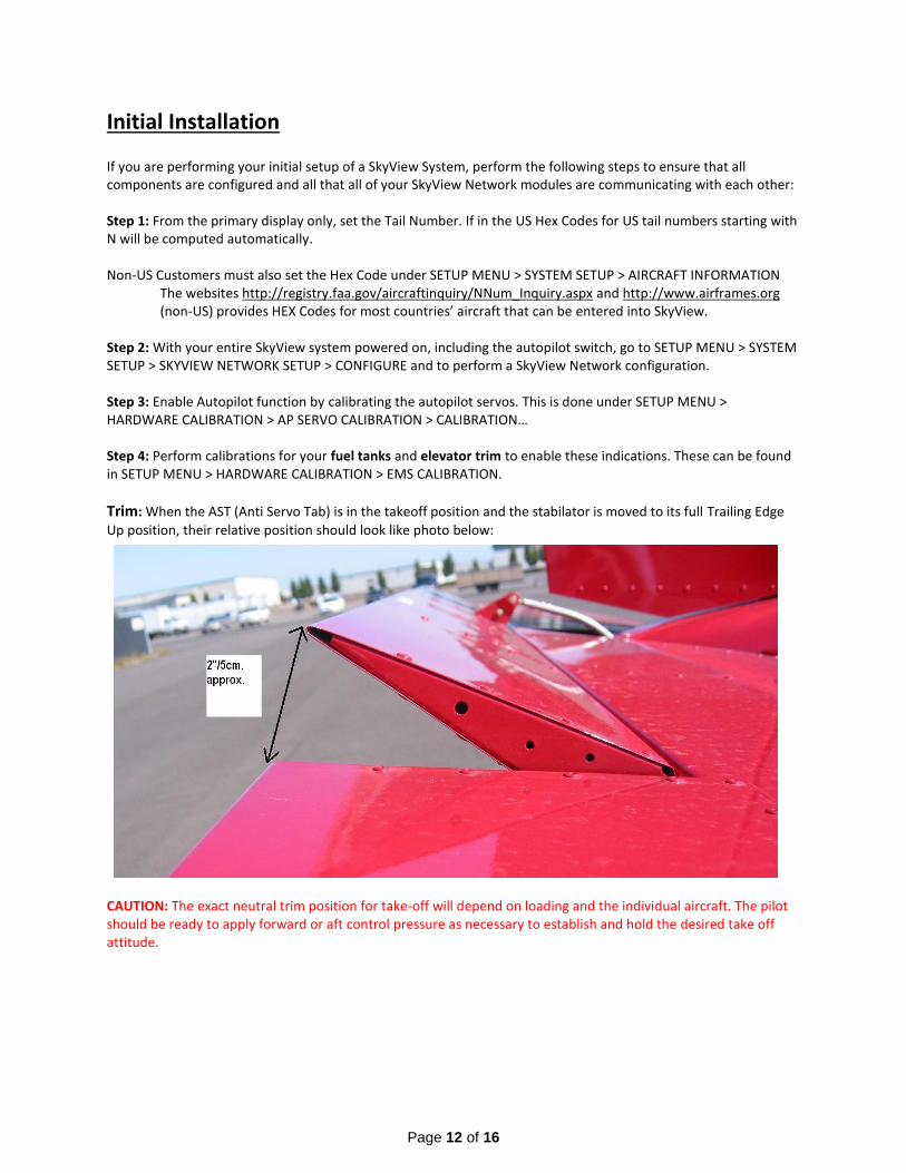
Trim: When the AST (Anti Servo Tab) is in the takeoff position and the stabilator is moved to its full Trailing Edge
Up position, their relative position should look like photo below:
CAUTION: The exact neutral trim position for take-off will depend on loading and the individual aircraft. The pilot should be ready to apply forward or aft control pressure as necessary to establish and hold the desired take off attitude.
Page 13 of 16
Takeoff Position With the AST in the correct position for take-off, raise the trailing edge of the stabilator until it hits the control stop. The AST should be in the position shown.
a) Enable the Auto-Pilot Auto-trim feature if the SV-AP-PANEL and SV-KNOB-PANEL are installed by
performing the required calibration steps. This is covered in Steps 9 and 10 above for aircraft that are upgrading from a software version before 12.0 software, which introduced this feature to all customers. It also applies to new installations.
b) If you have a SkyView SV-BAT-320 backup battery installed, perform the required Initial Backup Battery Test. Full instructions for this procedure are in the SkyView System Installation Guide.
Common Errors & Mistakes: Red X on Com and/or Transponder: Is the avionics switched on? Numerous functions randomly have a red X: Most likely the battery voltage has dropped too low. Place the aircraft on a battery charger. Transponder will not switch out of standby mode: Have you entered the HEX CODE? ADS-B/TIS shows “Not Available”: See Step 11 and Step 12. Autopilot not functioning: Is the autopilot switch on? Is the Autopilot fuse blown? Did you load the incorrect autopilot .dfg file or forget to load the file? See Steps 7 & 8. Have you performed the initial autopilot configuration steps? If you’ve never used the autopilot, it must be configured per the Dynon SkyView System Installation Guide. RV-12 SkyView Installation does not display frequencies from the COM radio on the SkyView: Download Section 42K from the RV-12 Service Information page of the Van’s Aircraft web site. Complete the last page of the section to add a missing wire that is most likely causing the problem. Difficulty with the system recognizing other items on the network: This could be the second screen, autopilot servos, etc. Try performing a network configure and/or force network load to clear up the problem. If you have a second dual screen both displays have to be at the same version of software / firmware. Update both displays to the latest software / firmware.
EGT: Some aircraft in the past have experienced EGT’s swapped left and right. After installing the software and settings from the Van’s Aircraft web site double check using a hair dryer or heat gun that the EGT’s are installed on the correct (left or right) side of the aircraft. If the sensors are backwards then swap the sensors at the junction of the thermocouple wires to the firewall forward harness. See KAI Section 48. Settings / flight data writing to USB but USB Stick is blank: If a USB memory stick is installed in the USB ports built into the back of the EFIS data will be written to those USB locations before being written to the remote USB location below the panel. Remove all Wi-Fi adaptors and USB sticks with charts etc from the back of the screen to regain functionality of the remote USB location. USB not recognized by EFIS screen: Try a different USB stick. Try a different computer. Try reformatting the USB stick. Mapping Software Error: The mapping software code is entered into the primary EFIS display before shipment to
Page 14 of 16
the customer. This code is loaded on the primary EFIS screen (PFD). The code will automatically transfer to the second screen (MFD) when connected to the primary. If your screen is displaying the error “Map Trial Mode” or “Trial Expired” then you do not have a map license entered. This could be because:
1) You bought an EFIS screen from another party (in which case you will need to purchase a new map license from Dynon)
2) The screen was repaired and returned from Dynon and the mapping code was not transferred to the new screen. Contact Dynon with the serial number on the back of your PFD screen and your RV-12 builder information. A new mapping code will be sent to you.
3) A new screen was shipped to you and the code was not setup before shipment. Contact Dynon with the serial number on the back of your PFD screen and your RV-12 builder information. A new mapping code will be sent to you.
NOTE: If any of the links or references within this read me are out of date, please notify us and as soon as time permits we will update this document.
Revision Summary: This summary tracks changes to the software settings files and the readme document. Rev 5 02-19-16
1) Support and Setup Information has been added for ADS-B out. We have added a new section for GPS and TRANSPONDER setup. ADS-B out will require installation of the new SV-GPS-2020 antenna, see notification N 16-01-16 available on the RV-12 service information page.
2) NOTE: Second GPS All 5 serial ports (ELT, ADS-B, XPNDR, COM, GPS) are in use. There is no room for a second GPS (if upgrading there is no room for the old SV-GPS-250 to be installed as a second GPS). Some older aircraft not using ELT may consider using that port for a second GPS (you are on your own if you go down this path!). We consider the positional accuracy provided by GPS data to the ELT to be of greater safety benefit than a second GPS. Remember this is a VFR aircraft.
3) Updated transponder software that must be installed from the EFIS setup menu after loading the main .duc file. We have added a step in the dfg section for transponder to help with this process.
4) Added best glide speed Vg and sink rate at Vg to the main settings file as well as turning on the glide ring by default. The best glide airspeed and sink rate will change with aircraft weight. The best glide parameters used are for a weight in the middle of the range between the stated RV-12 solo weight and max gross weight. These numbers are derived from testing with the engine stopped (simulating an emergency situation).
5) ADS-B is no longer reset as if not installed by the main settings file. Rev 6 06-16-16
1) Added a rev level and revision summary to the readme document to communicate rev changes to customers.
2) 12-SVXX.X-PRE-SETS-MM-DD-YY.duc File: Turned on terrain warning by default 3) 12-SVXX.X-PRE-SETS-MM-DD-YY.duc File: Va (maneuvering speed) changed to Va min (maneuvering speed
at minimum weight) 72kts. Va was 90kts or maneuvering speed at Va max (maneuvering speed at gross weight).
4) Added “Mapping Software Error: ….” to the Common Errors & Mistakes section. 5) Under Dual Screen Final Setup a new Step 21 was added to turn off the default connection of the second
screen to a backup battery. In a dual screen installation there is only one backup battery installed on the
Page 15 of 16
PFD (due to current limitations of the Rotax 912ULS generator).
Rev 7 01-25-17
1) Added reminder step for AOA setup. Rev 8 03-24-17
1) Modified ADS-B section for ADS-B 472 module. Rev 9 08-30-17
1) Add note to place the aircraft at aft cg when testing or adjusting the autopilot settings. Rev 10 04-06-18
1) Changed the fuel pressure color bands to match the settings on Garmin G3X. "Red 0-2.1, Green 2.1-7.3, Red 7.3-8" Was "Red 0-2.2, Yellow 2.2-3, Green3-5.8, Yellow 5.8-7.2, Red 7.2-8"
2) Changed the battery voltage color bands to match the settings on Garmin G3X. “Max display range was 15 now 16, Red 10-12 was 10-11.5, Yellow 12.0-13.1 was 11.5-13.7, Green 13.1-15.0 was 13.7-14.3, Red 15.0-16.0 was 16.6-15”
3) Configuration files for the engine voltage regulator type have been added to support the old Ducati regulator supplied with the Rotax 912ULS engines and the new Silent Hektik regulator now available as an option from Van’s Aircraft.
4) Removed Autopilot settings from the 12ZZZ-SkyView_Settings_vXX.XX.X_MM-DD-YY.dfg main settings file.
5) Van’s no longer includes a software .duc all in one (software and settings) file. Van’s will post a settings file on the web site. That settings file will have in the file name the latest Dynon software version that was tested with the settings file. The customer will then be responsible for downloading the software from Dynon.
WARNING! Van’s does not recommend installation of a newer software version than is indicated in the name of the settings file. If a newer version of software is installed that is beyond the version stated, problems may occur and Van’s will not be able to assist a customer. If you have installed a non-approved version of software please direct all questions to Dynon. The file “12ZZZ-SkyView_Settings_vXX.XX.X_MM-DD-YY” is the main settings file. This file will work for D1000(T) and HDX screens. ZZZ is the engine type ULS or iS vXX.X.X is the version of software from Dynon that has been tested with the provided settings. The settings have been tested to the best of our ability. If you find issues please report them to us and we will work with Dynon to resolve them as quickly as we can. MM-DD-YY was the day these settings were generated at Van’s. If a second update is required for a particular Dynon software version this date may change even though the software version does not. Please read the entire file name to determine if you have the latest settings file installed.
Page 16 of 16
Rev 11 08-29-18
1) In Step 2 we have clarified that a user should use the Dynon Software package including a Dynon EMS Sensor definitions file.
Rev 12 11-29-18
1) Additions were made for Rotax 912iS 2) Vo was Va (Note this change was required to meet changes to the ASTM Standard) 3) Made changes to clarify the procedure used to verify the Skyview software and Van’s Aircraft setting files
are compatible. 4) Step number changes in Steps 1 through 10/10A related to addition of a clarifying step. 5) Changed the FAA reference source for an ADS-B compliance report to the current source. 6) General clarifications and readability updates. 7) Changes to reflect inclusion of Skyview software and Dynon-provided settings files in the ZIP file that is
downloaded from Van’s, which in most cases removes the requirement to download some of the required files from Dynon.
8) Changes to the downloaded files, resulting in one file to download for Rotax 912ULS-equpped airplanes, and one file to download for Rotax 912iS-equipped airplanes.
Rev 13 05-23-19
1) For RV-12iS using a 912iS Sport engine with dual screen EFIS systems the .sfg for the fuel pressure sensor needs to be loaded on both screens. Step 9 for loading the fuel pressure sensor file was moved to Step 7. The old Step 7 was re-written and subsequent steps renumbered as required.