Embed Size (px)
Citation preview
Revision: 10.1 Date: 6/9/17
RV-12 PRODUCTION ACCEPTANCE PROCEDURES
AIRCRAFT SERIAL NUMBER: _______________ ASTM F 3035-13 states that the manufacturer (Van's Aircraft) shall maintain a Quality Assurance Record (QAR) for each LSA produced. The QAR shall consist of (among other records) "Applicable final inspection records, check, and test documentation from the production acceptance procedures" Van's Aircraft 14401 Keil Rd. NE Aurora, OR 97002 U.S.A.
Revision: 10.1 Date: 6/9/17
ii
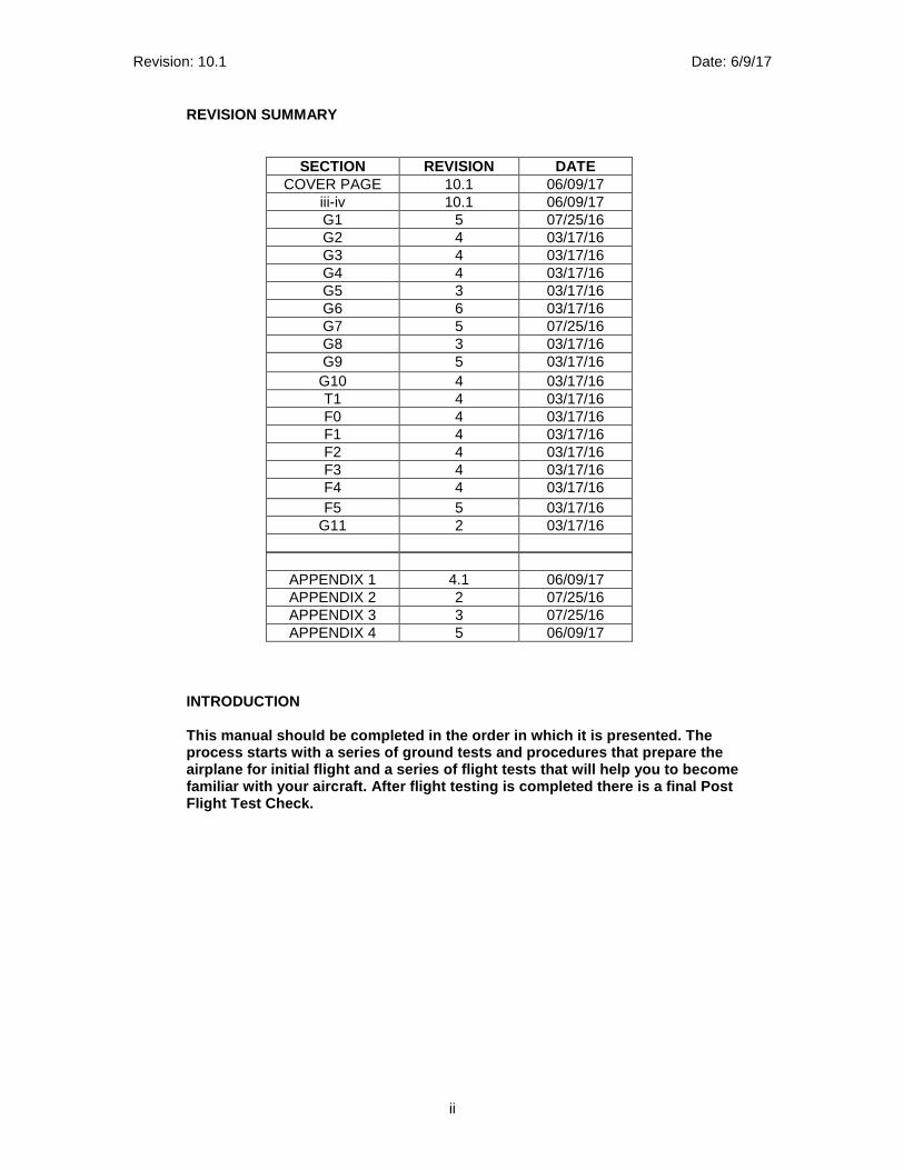
REVISION SUMMARY
APPENDIX 1 4.1 06/09/17 APPENDIX 2 2 07/25/16 APPENDIX 3 3 07/25/16 APPENDIX 4 5 06/09/17
INTRODUCTION This manual should be completed in the order in whi ch it is presented. The process starts with a series of ground tests and pr ocedures that prepare the airplane for initial flight and a series of flight tests that will help you to become familiar with your aircraft. After flight testing i s completed there is a final Post Flight Test Check.
SECTION REVISION DATE COVER PAGE 10.1 06/09/17
iii-iv 10.1 06/09/17 G1 5 07/25/16 G2 4 03/17/16 G3 4 03/17/16 G4 4 03/17/16 G5 3 03/17/16 G6 6 03/17/16 G7 5 07/25/16 G8 3 03/17/16 G9 5 03/17/16 G10 4 03/17/16 T1 4 03/17/16 F0 4 03/17/16 F1 4 03/17/16 F2 4 03/17/16 F3 4 03/17/16 F4 4 03/17/16 F5 5 03/17/16
G11 2 03/17/16
Revision: 10.1 Date: 6/9/17
iii
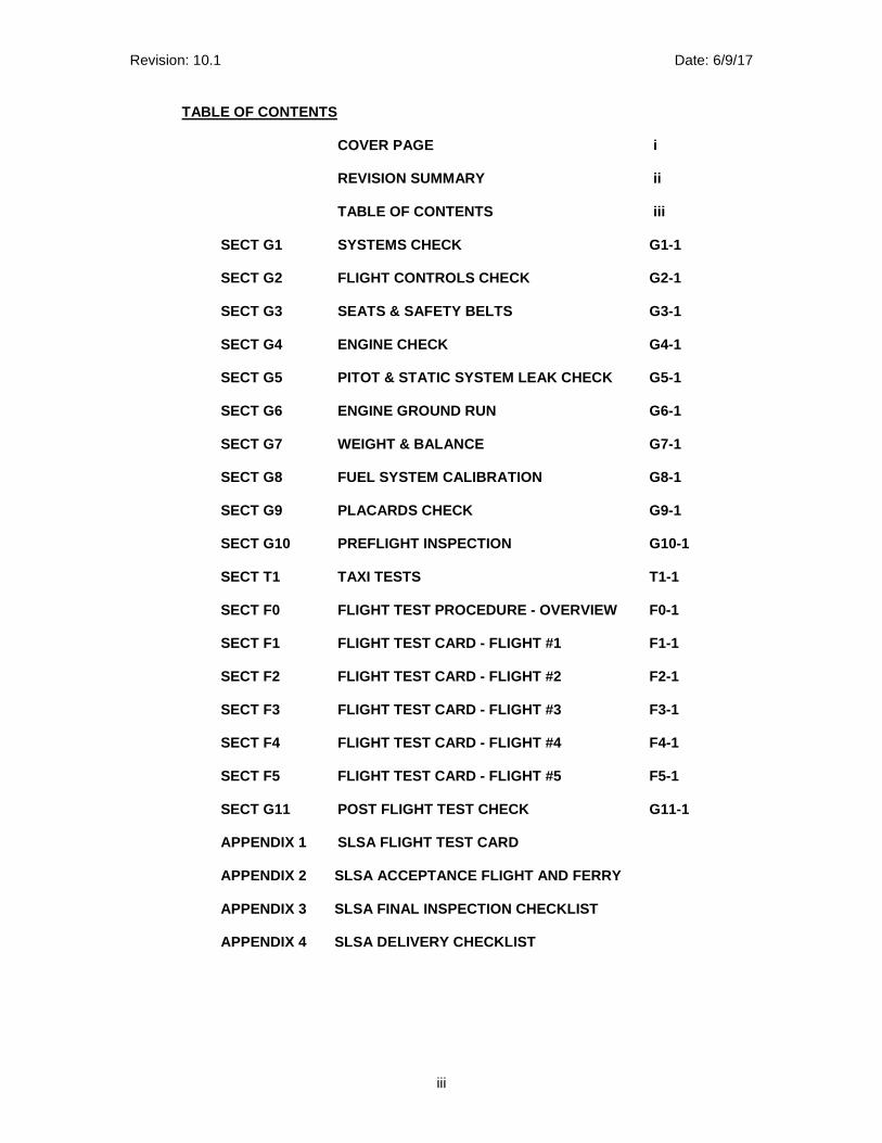
TABLE OF CONTENTS COVER PAGE i REVISION SUMMARY ii TABLE OF CONTENTS iii SECT G1 SYSTEMS CHECK G1-1 SECT G2 FLIGHT CONTROLS CHECK G2-1 SECT G3 SEATS & SAFETY BELTS G3-1 SECT G4 ENGINE CHECK G4-1 SECT G5 PITOT & STATIC SYSTEM LEAK CHECK G5-1 SECT G6 ENGINE GROUND RUN G6-1 SECT G7 WEIGHT & BALANCE G7-1 SECT G8 FUEL SYSTEM CALIBRATION G8-1 SECT G9 PLACARDS CHECK G9-1 SECT G10 PREFLIGHT INSPECTION G10-1 SECT T1 TAXI TESTS T1-1 SECT F0 FLIGHT TEST PROCEDURE - OVERVIEW F0-1 SECT F1 FLIGHT TEST CARD - FLIGHT #1 F1-1 SECT F2 FLIGHT TEST CARD - FLIGHT #2 F2-1 SECT F3 FLIGHT TEST CARD - FLIGHT #3 F3-1 SECT F4 FLIGHT TEST CARD - FLIGHT #4 F4-1 SECT F5 FLIGHT TEST CARD - FLIGHT #5 F5-1 SECT G11 POST FLIGHT TEST CHECK G11-1 APPENDIX 1 SLSA FLIGHT TEST CARD APPENDIX 2 SLSA ACCEPTANCE FLIGHT AND FERRY APPENDIX 3 SLSA FINAL INSPECTION CHECKLIST APPENDIX 4 SLSA DELIVERY CHECKLIST

Revision: 10.1 Date: 6/9/17
iv
THIS PAGE INTENTIONALLY LEFT BLANK
Revision: 5 Date: 7/25/16
G1-1
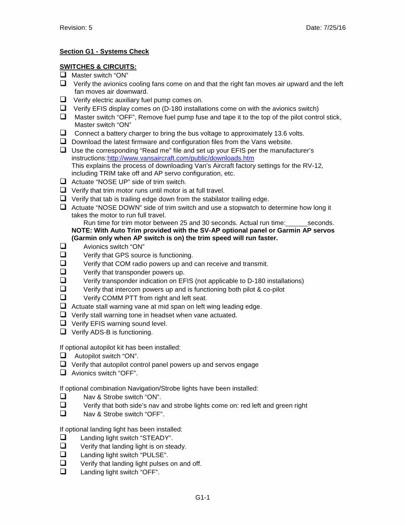
Section G1 - Systems Check SWITCHES & CIRCUITS: � Master switch “ON” � Verify the avionics cooling fans come on and that the right fan moves air upward and the left
fan moves air downward. � Verify electric auxiliary fuel pump comes on. � Verify EFIS display comes on (D-180 installations come on with the avionics switch) � Master switch “OFF”, Remove fuel pump fuse and tape it to the top of the pilot control stick,
Master switch “ON” � Connect a battery charger to bring the bus voltage to approximately 13.6 volts. � Download the latest firmware and configuration files from the Vans website. � Use the corresponding “Read me” file and set up your EFIS per the manufacturer’s
instructions: http://www.vansaircraft.com/public/downloads.htm This explains the process of downloading Van’s Aircraft factory settings for the RV-12, including TRIM take off and AP servo configuration, etc.
� Actuate “NOSE UP” side of trim switch. � Verify that trim motor runs until motor is at full travel. � Verify that tab is trailing edge down from the stabilator trailing edge. � Actuate “NOSE DOWN” side of trim switch and use a stopwatch to determine how long it
takes the motor to run full travel. Run time for trim motor between 25 and 30 seconds. Actual run time:______seconds.
NOTE: With Auto Trim provided with the SV-AP option al panel or Garmin AP servos (Garmin only when AP switch is on) the trim speed w ill run faster.
� Avionics switch “ON” � Verify that GPS source is functioning. � Verify that COM radio powers up and can receive and transmit. � Verify that transponder powers up. � Verify transponder indication on EFIS (not applicable to D-180 installations) � Verify that intercom powers up and is functioning both pilot & co-pilot � Verify COMM PTT from right and left seat. � Actuate stall warning vane at mid span on left wing leading edge. � Verify stall warning tone in headset when vane actuated. � Verify EFIS warning sound level. � Verify ADS-B is functioning. If optional autopilot kit has been installed: � Autopilot switch “ON”. � Verify that autopilot control panel powers up and servos engage � Avionics switch “OFF”. If optional combination Navigation/Strobe lights have been installed: � Nav & Strobe switch “ON”. � Verify that both side’s nav and strobe lights come on: red left and green right � Nav & Strobe switch “OFF”. If optional landing light has been installed: � Landing light switch “STEADY”. � Verify that landing light is on steady. � Landing light switch “PULSE”. � Verify that landing light pulses on and off. � Landing light switch “OFF”.
Revision: 5 Date: 7/25/16
G1-2
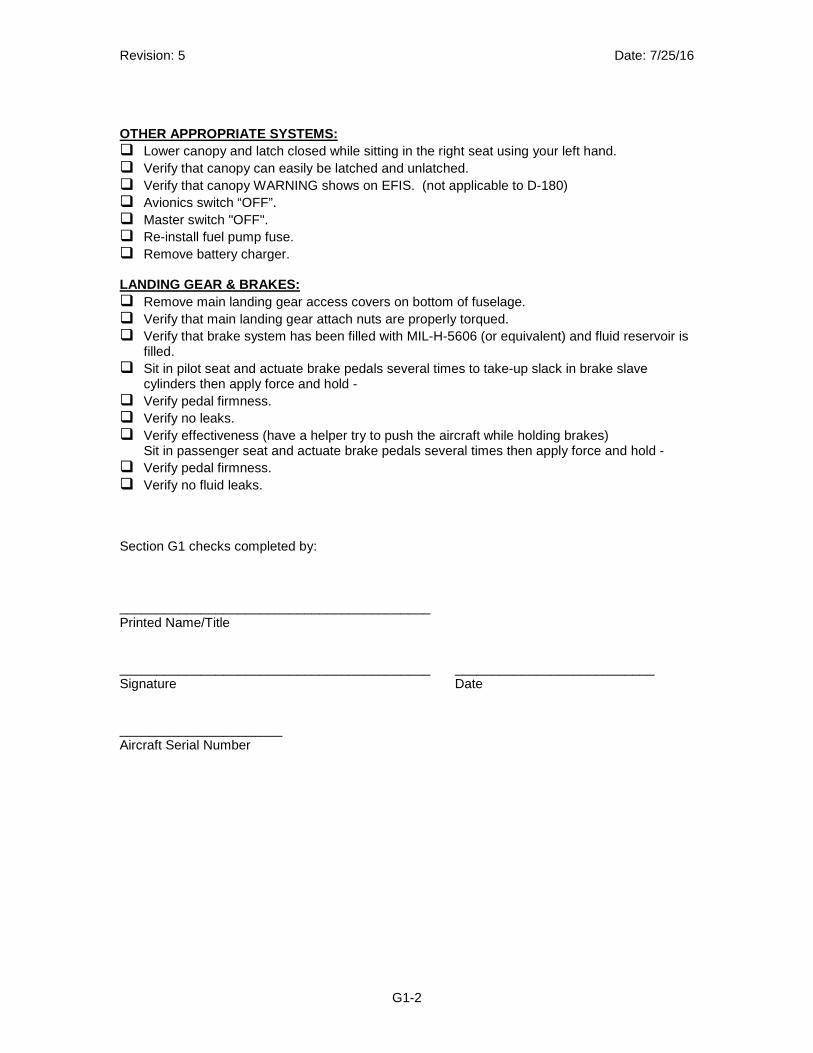
OTHER APPROPRIATE SYSTEMS: � Lower canopy and latch closed while sitting in the right seat using your left hand. � Verify that canopy can easily be latched and unlatched. � Verify that canopy WARNING shows on EFIS. (not applicable to D-180) � Avionics switch “OFF”. � Master switch "OFF". � Re-install fuel pump fuse. � Remove battery charger.
LANDING GEAR & BRAKES: � Remove main landing gear access covers on bottom of fuselage. � Verify that main landing gear attach nuts are properly torqued. � Verify that brake system has been filled with MIL-H-5606 (or equivalent) and fluid reservoir is
filled. � Sit in pilot seat and actuate brake pedals several times to take-up slack in brake slave
cylinders then apply force and hold - � Verify pedal firmness. � Verify no leaks. � Verify effectiveness (have a helper try to push the aircraft while holding brakes)
Sit in passenger seat and actuate brake pedals several times then apply force and hold - � Verify pedal firmness. � Verify no fluid leaks. Section G1 checks completed by: __________________________________________ Printed Name/Title __________________________________________ ___________________________ Signature Date ______________________ Aircraft Serial Number
Revision: 4 Date: 3/17/16
G2-1
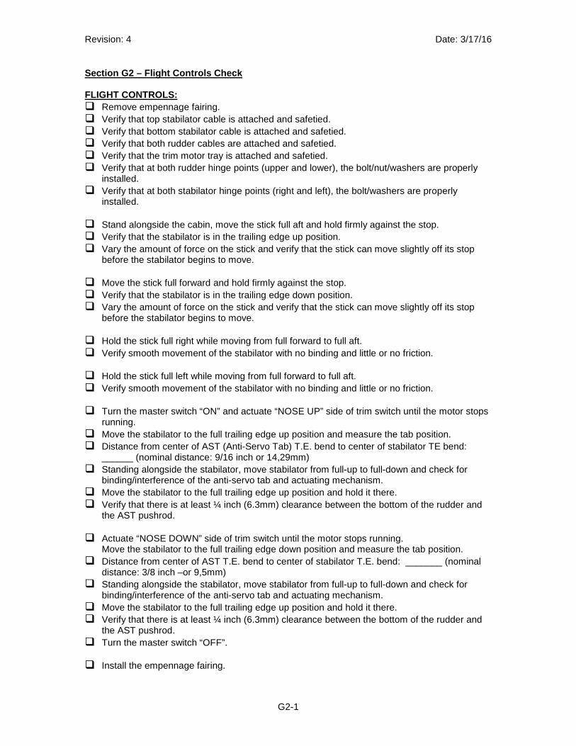
Section G2 – Flight Controls Check FLIGHT CONTROLS: � Remove empennage fairing. � Verify that top stabilator cable is attached and safetied. � Verify that bottom stabilator cable is attached and safetied. � Verify that both rudder cables are attached and safetied. � Verify that the trim motor tray is attached and safetied. � Verify that at both rudder hinge points (upper and lower), the bolt/nut/washers are properly
installed. � Verify that at both stabilator hinge points (right and left), the bolt/washers are properly
installed. � Stand alongside the cabin, move the stick full aft and hold firmly against the stop. � Verify that the stabilator is in the trailing edge up position. � Vary the amount of force on the stick and verify that the stick can move slightly off its stop
before the stabilator begins to move.
� Move the stick full forward and hold firmly against the stop. � Verify that the stabilator is in the trailing edge down position. � Vary the amount of force on the stick and verify that the stick can move slightly off its stop
before the stabilator begins to move.
� Hold the stick full right while moving from full forward to full aft. � Verify smooth movement of the stabilator with no binding and little or no friction.
� Hold the stick full left while moving from full forward to full aft. � Verify smooth movement of the stabilator with no binding and little or no friction. � Turn the master switch “ON” and actuate “NOSE UP” side of trim switch until the motor stops
running. � Move the stabilator to the full trailing edge up position and measure the tab position. � Distance from center of AST (Anti-Servo Tab) T.E. bend to center of stabilator TE bend:
______ (nominal distance: 9/16 inch or 14,29mm) � Standing alongside the stabilator, move stabilator from full-up to full-down and check for
binding/interference of the anti-servo tab and actuating mechanism. � Move the stabilator to the full trailing edge up position and hold it there. � Verify that there is at least ¼ inch (6.3mm) clearance between the bottom of the rudder and
the AST pushrod.
� Actuate “NOSE DOWN” side of trim switch until the motor stops running. Move the stabilator to the full trailing edge down position and measure the tab position.
� Distance from center of AST T.E. bend to center of stabilator T.E. bend: _______ (nominal distance: 3/8 inch –or 9,5mm)
� Standing alongside the stabilator, move stabilator from full-up to full-down and check for binding/interference of the anti-servo tab and actuating mechanism.
� Move the stabilator to the full trailing edge up position and hold it there. � Verify that there is at least ¼ inch (6.3mm) clearance between the bottom of the rudder and
the AST pushrod. � Turn the master switch “OFF”. � Install the empennage fairing.
Revision: 4 Date: 3/17/16
G2-2
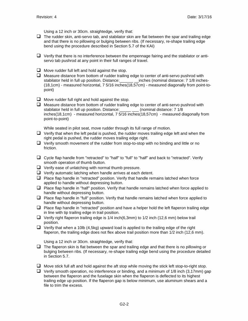
Using a 12 inch or 30cm. straightedge, verify that: � The rudder skin, anti-servo tab, and stabilator skin are flat between the spar and trailing edge
and that there is no pillowing or bulging between ribs. (If necessary, re-shape trailing edge bend using the procedure described in Section 5.7 of the KAI)
� Verify that there is no interference between the empennage fairing and the stabilator or anti-
servo tab pushrod at any point in their full ranges of travel.
� Move rudder full left and hold against the stop. � Measure distance from bottom of rudder trailing edge to center of anti-servo pushrod with
stabilator held in full up position. Distance:______ __inches (nominal distance: 7 1/8 inches- (18,1cm) - measured horizontal, 7 5/16 inches(18,57cm) - measured diagonally from point-to-point)
� Move rudder full right and hold against the stop. � Measure distance from bottom of rudder trailing edge to center of anti-servo pushrod with
stabilator held in full up position. Distance:_____ ___ (nominal distance: 7 1/8 inches(18,1cm) - measured horizontal, 7 5/16 inches(18,57cm) - measured diagonally from point-to-point) While seated in pilot seat, move rudder through its full range of motion.
� Verify that when the left pedal is pushed, the rudder moves trailing edge left and when the right pedal is pushed, the rudder moves trailing edge right.
� Verify smooth movement of the rudder from stop-to-stop with no binding and little or no friction.
� Cycle flap handle from "retracted" to "half" to "full" to "half" and back to "retracted". Verify
smooth operation of thumb button. � Verify ease of unlatching with normal thumb pressure. � Verify automatic latching when handle arrives at each detent. � Place flap handle in "retracted" position. Verify that handle remains latched when force
applied to handle without depressing button. � Place flap handle in "half" position. Verify that handle remains latched when force applied to
handle without depressing button. � Place flap handle in "full" position. Verify that handle remains latched when force applied to
handle without depressing button. � Place flap handle in "retracted" position and have a helper hold the left flaperon trailing edge
in line with tip trailing edge in trail position. � Verify right flaperon trailing edge is 1/4 inch(6,3mm) to 1/2 inch (12,6 mm) below trail
position. � Verify that when a 10lb (4,5kg) upward load is applied to the trailing edge of the right
flaperon, the trailing edge does not flex above trail position more than 1/2 inch (12,6 mm).
Using a 12 inch or 30cm. straightedge, verify that: � The flaperon skin is flat between the spar and trailing edge and that there is no pillowing or
bulging between ribs. (If necessary, re-shape trailing edge bend using the procedure detailed in Section 5.7.
� Move stick full aft and hold against the aft stop while moving the stick left stop-to-right stop. � Verify smooth operation, no interference or binding, and a minimum of 1/8 inch (3,17mm) gap
between the flaperon and the fuselage skin when the flaperon is deflected to its highest trailing edge up position. If the flaperon gap is below minimum, use aluminum shears and a file to trim the excess.
Revision: 4 Date: 3/17/16
G2-3
� Move stick full forward and hold against the forward stop while moving the stick left stop-to-right stop.
� Verify smooth operation, no interference or binding, and a minimum of 1/8 inch(3,17mm) gap between the flaperon and the fuselage skin when the flaperon is deflected to its highest up position. If the flaperon gap is below minimum, use aluminum shears and a file to trim the excess.
� Verify that the left flaperon moves trailing edge up when the stick is moved left and vice versa.
� Place flap handle in "half" position. � Move stick full aft and hold against the aft stop while moving the stick left stop-to-right stop.
Verify smooth operation, no interference or binding. � Move stick full forward and hold against the forward stop while moving the stick from left stop-
to-right stop. Verify smooth operation, no interference or binding.
� Place flap handle in "full" position. � Move stick full aft and hold against the aft stop while moving the stick from left stop-to-right
stop. Verify smooth operation, no interference or binding. � Verify that the stabilator cable turnbuckles have safety pins installed. � Verify that the stabilator cable tension is adjusted such that when the stick is "pulsed" fore
and aft, the cables do not slap against the aircraft structure. Section G2 checks completed by: __________________________________________ Printed Name/Title __________________________________________ ___________________________ Signature Date ______________________ Aircraft Serial Number
Revision: 4 Date: 3/17/16
G3-1
Section G3 - Seats and Safety Belts OCCUPANT RESTRAINT:
Pilot side Lap Belt: � Verify security of attachment, 2 places, left and right. � Verify no visual defects (signs of fraying, wear, loose stitching, etc)
Pilot side Shoulder Belt: � Verify security of attachment. � Verify no visual defects (signs of fraying, wear, loose stitching, etc)
Pilot side Crotch Belt: � Verify security of attachment. � Verify no visual defects (signs of fraying, wear, loose stitching, etc)
Passenger side Lap Belt: � Verify security of attachment, 2 places, left and right � Verify no visual defects (signs of fraying, wear, loose stitching, etc)
Passenger side Shoulder Belt: � Verify security of attachment. � Verify no visual defects (signs of fraying, wear, loose stitching, etc)
Passenger side Crotch Belt: � Verify security of attachment. � Verify no visual defects (signs of fraying, wear, loose stitching, etc)
Seat backs and cushions: � Verify seat backs are in desired positions and hinge pins installed (left and right) � Verify seat cushions in place and fit well to seat back and cabin floor (left and right) � Verify that at any point in sticks' range of motion there is no interference with seat cushion.
Occupant restraint latching/unlatching: � Sit in seat and latch and adjust the belts such that the lap belt is low on hips, the crotch belt is
adjusted such that restraint buckle cannot be pulled higher than occupant's navel, and the shoulder belt is adjusted with minimum amount of slack such that all controls can be reached and operated.
� Verify that pilot side restraint system stays latched and adjusted while throwing body weight alternately against shoulder belts then seatback.
� Verify that passenger side restraint system stays latched and adjusted while throwing body weight alternately against shoulder belts then seatback.
Section G3 checks completed by: __________________________________________ Printed Name/Title __________________________________________ ___________________________ Signature Date ______________________ Aircraft Serial Number
Revision: 4 Date: 3/17/16
G4-1
Section G4 - Engine Check ENGINE: � Remove cowling, upper and lower. � Verify proper engine attachment. � Verify proper exhaust system attachment.
Throttle control: � Verify proper attachment. � Verify proper operation (observe carburetors while having a helper operate the throttle knob
from the cabin) Choke control:
� Verify proper attachment. � Verify proper operation (observe carburetors while having a helper operate the choke control
from the cabin)
Cabin heater control: � Verify proper attachment. � Verify proper operation (observe cabin heat door while having a helper operate the heater
control from the cabin) � Fill cooling system in accordance with Rotax SI for this procedure (use of standard coolant is
recommended).
� Fill oil system in accordance with Rotax SI procedure.
Gascolator testing: � Add 4 gallons of fuel to the tank. � Move fuel valve to ON position. � Turn master switch "ON". Verify no fuel leaks. Turn master switch "OFF". � Disconnect fuel line at gascolator outlet. � Slide a piece of 5/16 inch (8mm) inside diameter rubber hose over the gascolator outlet fitting
and feed into a bucket at waist height. � Charge battery to full. Voltage should read at least 12.7v. � Turn master switch "ON", reduce load on the electrical system by turning off strobes and nav
lights, dimming screens, etc. Turn fuel valve "ON". � Time from master switch on until 1 gallon has emptied into bucket: ________________ (Max
Time: 180 seconds) � Re-connect fuel line at gascolator outlet. � Filter fuel and put back into the fuel tank. � Remove lower spark plug from each cylinder
Propeller and spinner installation: � Remove spinner. � Check prop blade pitch setting (blades both at same pitch angle) See KAI Section 47 � Check prop bolt torque. � Check prop tracking (difference between blades must be less than 1/8 inch (3,17mm)) � Re-install spinner. � Check pitot tube tracking (max difference must be less than 1/16 inch (1,6mm))
Revision: 4 Date: 3/17/16
G4-2
� Unlatch one wing pin at a time and verify red warning light comes on and starter circuit is disabled.
� Install lower spark plugs in all cylinders. � Install lower cowl. Section G4 checks completed by: __________________________________________ Printed Name/Title __________________________________________ ___________________________ Signature Date ______________________ Aircraft Serial Number
Revision: 3 Date: 3/17/16
G5-1
Section G5 - Pitot system and static system leak ch eck Using 35cc syringe, push plunger in to 7.5cc, hook-up syringe & vacuum hose to pitot tube, turn-on EFIS, use syringe to slowly, carefully push air into pitot, look for airspeed indication on EFIS, push-in syringe until 130 kt indicates, stop pushing-in. Start stopwatch when EFIS indicates 120 kt Time when EFIS indicates 110 kt: _______seconds. Time when EFIS indicates 100 kt: _______seconds. Time when EFIS indicates 90 kt: _______seconds. Time when EFIS indicates 80 kt: _______seconds. Maximum allowable pitot system leak rate is 10 kt in one minute. Tape-over one of the static ports, fully push-in syringe plunger and use modeling clay to hook-up syringe & vacuum hose to the other static port, use syringe to draw-out air from static system. Look for altitude indication on EFIS, draw syringe out until 1,200 ft above current elevation indicates, stop drawing-out. Start stopwatch when EFIS indicates 1000 ft Time when EFIS indicates 900 ft: _______seconds. Time when EFIS indicates 800 ft: _______seconds. Time when EFIS indicates 700 ft: _______seconds. Time when EFIS indicates 600 ft: _______seconds. Maximum allowable static system leak rate is 100 ft in one minute. Section G5 checks completed by: __________________________________________ Printed Name/Title __________________________________________ ___________________________ Signature Date ______________________ Aircraft Serial Number
Revision: 6 Date: 3/17/16
G6-1
Section G6 - Engine ground run (Note: This section must be done with the aircraft outside.) � Add approximately 2 gallons fuel to tank. � Chock main wheels, tie-down tail. � Master switch "ON", avionics switch "ON" then power-down transponder, com radio, and
GPS
Check EFIS for: � Fuel pressure indication. � Ammeter functioning and showing discharge. � Voltmeter functioning and showing more than 12.0 volts.
Start engine, check for: � Tachometer function. � Oil pressure functioning and showing pressure. � Ammeter functioning and showing charge. � Voltmeter functioning and showing 13 volts or higher. � EGT functioning (both cylinders) � CHT functioning (both cylinders) � Fuel flow functioning.
Once oil temperature has come up to 122 degrees F (50ºC), � Perform carburetor synchronization procedure as called-out in Section 11 of the RV-12
Maintenance Manual. � Run-up to 4000 rpm then check each ignition. � At 4000rpm latch and unlatch the canopy to verify audio and visual warnings (not applicable
to D-180) of canopy latch open. Rotate the canopy handle back and forth in the recessed groove within the canopy latch block to insure that no condition exists in which the canopy is latched but the switch shows the canopy is open.
� Reduce to 3000rpm latch and unlatch canopy and verify no warning is given. � Check heater control operation. � Throttle to idle, note RPM, smoothness of run. � Check tachometer indication, engine idle at 1600-1650 RPM after engine is warmed to at
least 165 ºF (74ºC). � Verify functionality of throttle springs. (See RV-12 Maintenance Manual Page 12-14). � Shut down aircraft. � Remove lower cowl, check for: � Check oil, coolant, or fuel leaks. � Anything missing or loose (nuts, wires, sensor connections, etc) � Remove any remaining fuel by removing gascolator bowl and running electric fuel pump until
no more fuel comes out. Note presence of any debris in gascolator bowl and clean screen then re-install gascolator bowl and safety.
� Remove carburetor bowls and check for debris. Section G6 checks completed by: __________________________________________ __________________________ Printed Name/Title Aircraft Serial Number __________________________________________ ___________________________ Signature Date
Revision: 5 Date: 7/25/16
G7-1
Section G7 - Weight and Balance � Complete the weight and balance procedure found in Chapter 1 of the RV-12 Maintenance
Manual. Section G7 checks completed by: __________________________________________ Printed Name/Title __________________________________________ ___________________________ Signature Date ______________________ Aircraft Serial Number
Revision: 3 Date: 3/17/16
G8-1
Section G8 - Fuel system calibration � Roll aircraft onto 2 inch (5cm) blocks under main wheels and chock wheels.
� Add fuel incrementally and map quantity indication according to EFIS manual. � After four gallons of fuel have been added, roll aircraft off blocks and allow fuel to settle.
Verify the mechanical fuel gauge indicates below the top or at the top of the red "NO TAKE OFF" arc. If it does not, remove the red arc sticker and request a replacement IE-00002 Fuel Gauge Sticker from Van's Aircraft. Place the top of the red arc on the needle with four gallons of fuel in the tank.
� Roll aircraft back onto blocks and continue adding fuel incrementally and mapping quantity indication until 16 gal. (60,5L) have been added.
Section G8 checks completed by: __________________________________________ Printed Name/Title __________________________________________ ___________________________ Signature Date ______________________ Aircraft Serial Number
Revision: 5 Date: 3/17/16
G9-1
Section G9 - Placards check � Verify that N number is on outside of aircraft, 2 places. � Verify the N numbers are 12 inches high (S-LSA) � Verify that stainless steel data plate is on outside of aircraft. � Verify that N number is on instrument panel. � Verify that EXPERIMENTAL (for ELSA) or LIGHT-SPORT (for SLSA) placard is on baggage
bulkhead. � Verify that instrument panel switches and fuses are all labeled. � Verify that “OPEN” canopy latch placard is on outside of rear window. � Verify that Fuel type and capacity placard is on outside near fuel cap. � Verify that THROTTLE is above throttle knob and PUSH OPEN is on knob end. � Verify that CABIN HEAT is above cabin heat knob and PULL ON is on knob end. � Verify that PULL ON & ROTATE TO LOCK is below choke control. � Verify that CHOKE is above choke control. � Verify that fuel valve on/off placard is adjacent to fuel valve. � Verify that baggage capacity maximum 50 lbs (22,68kg) on baggage bulkhead. � Verify that No Push placards (2 places) are on anti-servo tab. � Verify that Minimum Fuel for Take-Off sticker is on mechanical fuel gauge. � Verify that Passenger warning placard is on instrument panel. � Verify that Autopilot disconnect is adjacent to AP disconnect switch. � Verify that 12 Volt Power Outlet 5A max placard is adjacent to power outlet. � Verify that Music Input placard is adjacent to receptacle. � Verify that inlet duct seal caveat placard is on top of inlet duct. � Verify that ELT labels are placed on instrument panel adjacent to ELT switch and adjacent to
ELT. � Verify that spare fuse holder (on map box door or under panel in front of pilot) has fuse
positions labeled. Section G9 checks completed by: __________________________________________ Printed Name/Title __________________________________________ ___________________________ Signature Date ______________________ Aircraft Serial Number
Revision: 4 Date: 3/17/16
G10-1
Section G10 - Preflight inspection
Verify that the following required documentation is on board: � Airworthiness certificate (must be visible at the entrance of the aircraft) � Registration certificate. � Pilot's Operating Handbook. � Completed & signed Weight and Balance worksheet. � Operating limitations. � Perform a complete Preflight inspection as called-out in Section 4 of the Pilot Operating
Handbook. � Visible surfaces are free of deformation or distortion. � All visible connections and fittings are securely attached. � Verify aircraft insurance is active if applicable. � Record of type of authorization issued to conduct the flight testing. � ________________________________ (Example: 8130-6 Special Flight Permit) Section G10 checks completed by: __________________________________________ Printed Name/Title __________________________________________ ___________________________ Signature Date ______________________ Aircraft Serial Number
Revision: 4 Date: 3/17/16
T1-1
Section T1 - Taxi Tests. � Start engine and verify proper engine and systems operation. � Verify that brakes can hold the aircraft stationary with power at up to 2500 rpm. � Taxi slowly and make sure that brakes are functioning and that the aircraft can easily be
brought to a full stop. � Taxi slowly and verify that the aircraft tracks straight with rudder held straight and without use
of brakes. (This must be done on a level taxiway and with less than 5 knots wind) � � Verify that, when taxiing at 15 kt or faster, aircraft can be steered using rudder only and no
brakes. � Verify that with one brake locked, the aircraft can be pivoted or spun 360 degrees on one
wheel. Perform this task in both directions.
CAUTION: Rapid application of throttle or high RPM may lift canopy open
� Latch Canopy
� Once oil temperature has reached at least 122 degrees F (50ºC), perform a 4000 rpm runup and verify that the brakes can hold the aircraft stationary.
� Verify that the aircraft can be held stationary with the engine at full throttle. � Taxi at progressively higher speeds up to but not exceeding 25 knots. At each speed, verify
that aircraft can be accurately steered using only rudder and that the aircraft can be rapidly brought to a stop while tracking in a straight line. Pay attention to the amount of rudder input necessary to counteract engine torque and to keep the airplane straight on the runway. Watch out for rapid applications of throttle at low speeds.
� Perform brake pad conditioning per Matco instructions then let brakes cool for five minutes. � Perform magnetometer calibration according to EFIS manual. � After shut down move the aircraft approximately 3 aircraft lengths by hand to verify that both
brakes are fully releasing and are not dragging. Section T1 checks completed by: __________________________________________ Printed Name/Title __________________________________________ ___________________________ Signature Date ______________________ Aircraft Serial Number

Revision: 4 Date: 3/17/16
T1-2
THIS PAGE INTENTIONALLY LEFT BLANK
Revision: 4 Date: 3/17/16
F0-1
Section F0 – Flight Test Procedure - Overview. The flight test procedure has been developed to verify that: • The aircraft is fully functional. • The aircraft is in proper trim. • Calibrations and adjustments, if required, have been made. • The flight performance matches that given in the POH. • The small variables inherent between individual aircraft do not adversely affect handling
qualities. Conforming versus Non-conforming Aircraft Aircraft of proven design (such as the RV-12) which have been built in conformity with the design standard usually pose few challenges to their test pilots even in the early hours of flight. However, this ideal must not be assumed therefore the “test” pilot must be prepared for any irregularity which may occur. Seemingly small or insignificant "modifications" to the proven and tested design standard should not be taken lightly as they often have far reaching implications to flying qualities, structural strength, and/or performance. Thus an RV-12 with a configuration not conforming to the design standard requires a completely different approach to flight test. The approach required for flight testing a non-conforming RV-12 must be identical to that of a completely new design. The procedure given in this document does not even begin to address what is required in that situation. Test Pilot Qualifications: A test pilot must have at least the following qualifications: • Be physically fit, mentally and emotionally stable. Test flying an aircraft is a stressful and
strenuous occupation. • Be rated and have recent experience in the RV-12 or similar low wing Rotax 912 powered
Light Sport Aircraft. • Have current medical, flight review, and insurance. A test pilot must do at least the following preparation: • Be familiar with the airport and nearby emergency fields. • Be able to demonstrate a high level of skill in all planned test maneuvers in an airplane with
similar characteristics. • Study the emergency procedures for the test aircraft and practice them in a similar airplane. • Have at least an hour of practice in recovery from unusual attitudes within 30 days of the
flight test. • Learn everything possible about the test aircraft by reading the POH, FTS, aviation magazine
flight reviews, watch videos, etc. • Become very familiar and comfortable with the aircraft's cabin and be able to select and
operate all controls by position only and without visual reference. A test pilot must have a professional attitude toward the task at hand: • After each flight, the test pilot must perform a self-debrief. • A professional reviews what happened during the flight: wrong and right using that
information to mentally prepare for the next flight. • A test pilot must not rush between flights, but allow time for absorbing or digesting the
lessons learned from the previous flight. • Whenever some small problem occurs; some unexplained vibrations, a slight binding of the
controls or the like, correct it before the next flight. NEVER let things go.
Revision: 4 Date: 3/17/16
F0-2
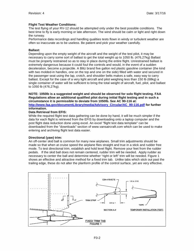
Flight Test Weather Conditions: The test flying of your RV-12 should be attempted only under the best possible conditions. The best time to fly is early morning or late afternoon. The wind should be calm or light and right down the runway. Performance data recordings and handling qualities tests flown in windy or turbulent weather are often so inaccurate as to be useless. Be patient and pick your weather carefully. Ballast: Depending upon the empty weight of the aircraft and the weight of the test pilot, it may be necessary to carry some sort of ballast to get the total weight up to 1050 lb. (476,27kg) Ballast must be properly restrained so as to stay in place during the entire flight. Unrestrained ballast is extremely dangerous because it could foul the controls and would, in the event of a sudden deceleration, become a projectile. A Blitz brand five gallon red plastic gasoline container (the kind with two molded-in handles, one on the top and one on the side) filled with water and secured in the passenger seat using the lap, crotch, and shoulder belts makes a safe, easy way to carry ballast. Except for the case of a very light aircraft and pilot weighing less than 150 lb (68kg) a single container of water will be sufficient to bring the total weight of aircraft, fuel, pilot, and ballast to 1050 lb (476,27kg). NOTE: 1050lb is a suggested weight and should be ob served for solo flight testing. FAA Regulations allow an additional qualified pilot dur ing initial flight testing and in such a circumstance it is permissible to deviate from 1050 lb. See AC 90-116 at: http://www.faa.gov/documentLibrary/media/Advisory_C ircular/AC_90-116.pdf for further information. Data Retrieval from EFIS: While the required flight test data gathering can be done by hand, it will be much simpler if the data for each flight is retrieved from the EFIS by downloading onto a laptop computer and the post flight data reduction done using excel. An excel "flight test data template" can be downloaded from the "downloads" section of www.vansaircraft.com which can be used to make entering and archiving flight test data easier. Directional (yaw) trim: An off-center skid ball is common for many new airplanes. Small trim adjustments should be made so that when at cruise speed the airplane flies straight and true in a stick and rudder free mode. To test directional trim, establish and hold level flight. Remove your feet from the rudder pedals. If the skid ball does not remain centered, rudder trim will be needed. Apply rudder as necessary to center the ball and determine whether “right or left” trim will be needed. Figure 1 shows an effective and attractive method for a fixed trim tab. Unlike tabs which stick out past the trailing edge, these do not alter the planform profile of the control surface, yet are very effective.
Revision: 4 Date: 3/17/16
F0-3
A temporary tab of this type can be made of wood, sawed into a wedge about 3/8 inch at the thick edge and 1 1/4 (28,57mm) to 1 1/2 (38mm) inches wide. This can be temporarily taped on to the rudder trailing edge near bottom and adjusted simply by trimming the length. Attach to the side of the rudder opposite that of the rudder pedal effort needed to center the ball. It may take several flights to determine the exact size. Then the temporary wedge can be replaced by a wedge made of machined aluminum, plastic, or sealed wood, and attached with flush pop rivets. An optional adjustable trim tab kit may be ordered part number “12 RUDDER TRIM KIT”. Lateral (roll) trim: A roll tendency that increases with speed is common for many new airplanes. Small trim adjustments should be made so that when at cruise speed with the skid ball centered the airplane has very little or no natural tendency to roll in either direction. To test roll trim, establish and hold level flight and center the skid ball with the rudder (if aircraft not in directional trim). Release the stick and note any roll tendency or “heavy wing”. There is a good chance that any given RV-12 will be out-of-trim laterally, requiring a trim adjustment. Because of the structure of RV-12 flaperons, roll trim can be varied through alteration of the aileron trailing edge bend radius. The theory behind this phenomenon is thus: The high pressure air on the lower surface tends to flow up around the trailing edge into the lower pressure on the upper surface. The size of the trailing edge radius affects these flow patterns and thus causes the aileron to lift or drop because of the “jet” effect of the attached airflow being deflected upwards. Altering just one aileron will have the same general effect as adding a trim tab. Experience has shown that roll trim can be achieved by decreasing or “tightening” the trailing edge of the aileron on the "light" wing - the one coming up as the airplane rolls. If the trailing edge is too blunt, squeezing it tighter (with just your fingers) along the length of the flaperon can have an effect. The result should be a barely perceptible change in shape, as gauged by sighting down a straight edge laid on the skin. Small variations in shape can have very noticeable affects on control. Fly the airplane to gauge the result. Several such trial-and-error attempts may be needed to achieve the desired results. If an over-correction occurs, it can be corrected in two ways. The opposite aileron’s trailing edge can be reduced slightly in the above manner. This is OK providing that the aileron control forces have not increased too much. As the trailing edge radius decreases, stick force increases. Also, the skins will crack if squeezed too tight. Expand the trailing edge radius, which has been squeezed too much. This can be achieved in an unlikely manner, with a board and a hammer. Yes, by holding a length of board such as a 2x2 butted up against the trailing edge and tapping the board along its length with the hammer, the radius can be “opened” up slightly—enough to have an effect on trim. But, be very careful. An extreme case of large trailing edge radii on the ailerons can cause a condition known as “aileron snatch”. The “snatch” is recognizable by the tendency of the ailerons to seek a neutral (stick free) point to one side or the other of center. Aileron snatch causes an uncomfortable control situation for the pilot because the control stick must be held in the center. Movement in either direction will initially be self driven for the first bit of travel, then normal loads begin to build as with additional stick deflection. When moving the stick from one side to the other, an area of control force reversal will be experienced when passing through center. Stick free, aileron snatch will result in a rolling tendency. A fixed trim tab will not correct this as it would just push the ailerons over center to one side, rather than returning them to center as desired. Correcting aileron snatch can usually be accomplished by reducing the trailing edge shape and radii to that shown on the plans.
Revision: 4 Date: 3/17/16
F0-4
Stall Testing Mild, power off stalls will be explored during the initial test flight. After more confidence in the aircraft is gained, the pilot should proceed to perform stalls entered from all anticipated flight conditions. All types of stalls should be practiced; departure (climbing) stalls, approach (gliding) stalls, stalls with varying degrees of bank, stalls at minimum and maximum weights, cross-control stalls, and accelerated stalls. Stalls at every imaginable attitude and from every imaginable entry condition. The object is not only to gain familiarity with stalls from every conceivable flight condition, but to become comfortable with recognition of and recovery from these stalls. Not comfortable in the sense of being careless, but comfortable in the sense of being confident in your ability to control any situation. Practicing many and varied stalls will heighten your awareness of attitudes and flight conditions to be avoided because of the severity of the stalls which might result from them. Except for accelerated stalls and secondary stalls, approach each slowly (a deceleration rate of not more than 1 kt per second is recommended) while correcting for P-Factor (for power stalls) with the rudder. Allow the speed to bleed off until you feel a slight buffet. Note the airspeed and recover with a smooth forward movement of the stick as power is added. Maybe simply relieving back pressure on the stick when the stall occurs would be sufficient for your airplane. Stalls entered from steep bank or climb attitudes will require more aggressive recovery control application. But remember, at some loading conditions, an RV-12 has light elevator forces, and over controlling can easily occur, and secondary stalls can be encountered. After gaining familiarity with stalls with instant recovery, delayed recovery can be practiced. Starting with wings level, 1 G stalls, delay the recovery by a count of 1, 2, 3, etc. seconds. The only purpose of this is to gain further experience with handling qualities in extreme conditions and to determine your ability to control the aircraft in a prolonged stalled mode. While one should always recover immediately at the first warning of an accidental stall, intentionally holding the airplane in a stall will provide the pilot with a greater experience base. While testing stalls, the pilot is not only gaining familiarity with that specific airplane for his piloting benefit, but is also evaluating that airplane’s stall characteristics against an ideal. The ideal is that when a stall is encountered, the nose tends to lower, or can easily be lowered by an easing of stick back pressure or by a forward stick pressure. The other characteristic being evaluated is a laterally uniform stall—or what is often called a straight forward stall. Airfoil irregularities, wing incidence misalignment, and wing twist can cause one wing to stall at a higher speed than the other. This obviously will cause one wing to drop when the stall occurs. This is not uncommon for RVs, and if the extent of wing drop is slight, no more than 15 degrees, it is of little consequence. Stall Warning Adjustment The stall warning tone should come-on 7 kt (plus or minus 2 kt) prior to the actual stall break. If the warning comes on too soon then the vane should be adjusted up slightly. If the warning comes on too close to the stall, then the vane should be adjusted down. Fuel Flow Calibration The fuel totalizer calibration should be done in accordance with the EFIS manual. After the first few cycles of fueling the aircraft, comparing fuel actually added to what the totalizer indicates, then correcting the "k" factor you should be getting fairly close to a final value. The fuel flow indication of the RV-12 can be fairly close but, because of the fact that the fuel returned to the tank is not accounted for, it will not be exactly correct for every flight. Experience has shown that a "k" factor adjustment made after a cross country flight of approximately three hours at nearly constant power setting will serve to very closely calibrate the system. This must, of course, be done after the initial flight test period is finished and the aircraft has been cleared to leave the designated test area.
Revision: 4 Date: 3/17/16
F0-5
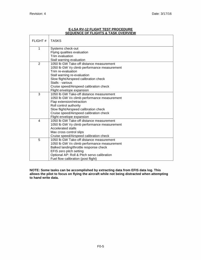
E-LSA RV-12 FLIGHT TEST PROCEDURE
SEQUENCE OF FLIGHTS & TASK OVERVIEW
FLIGHT # TASKS
1 Systems check-out Flying qualities evaluation Trim evaluation Stall warning evaluation
2 1050 lb GW Take-off distance measurement 1050 lb GW Vy climb performance measurement Trim re-evaluation Stall warning re-evaluation Slow flight/Airspeed calibration check Stalls - various Cruise speed/Airspeed calibration check Flight envelope expansion
3 1050 lb GW Take-off distance measurement 1050 lb GW Vx climb performance measurement Flap extension/retraction Roll control authority Slow flight/Airspeed calibration check Cruise speed/Airspeed calibration check Flight envelope expansion
4 1050 lb GW Take-off distance measurement 1050 lb GW Vy climb performance measurement Accelerated stalls Max cross control slips Cruise speed/Airspeed calibration check
5 1050 lb GW Take-off distance measurement 1050 lb GW Vx climb performance measurement Balked landing/throttle response check EFIS zero pitch setting Optional AP: Roll & Pitch servo calibration Fuel flow calibration (post flight)
NOTE: Some tasks can be accomplished by extracting data from EFIS data log. This allows the pilot to focus on flying the aircraft wh ile not being distracted when attempting to hand write data.

Revision: 4 Date: 3/17/16
F0-6
THIS PAGE INTENTIONALLY LEFT BLANK
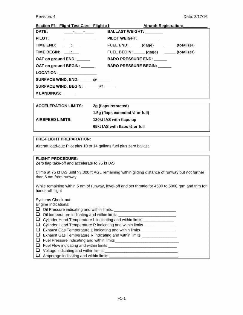
Revision: 4 Date: 3/17/16 Section F1 - Flight Test Card - Flight #1 Aircraft Registration:___________
F1-1
DATE: ____-____-____ BALLAST WEIGHT: ________
PILOT: ______________ PILOT WEIGHT: _________
TIME END: ___:___ FUEL END: _____ (gage) _____ (to talizer)
TIME BEGIN: ___:___ FUEL BEGIN: _____ (gage) _____ (totalizer)
OAT on ground END: ______ BARO PRESSURE END: _____ _
OAT on ground BEGIN: ______ BARO PRESSURE BEGIN: __ ____
LOCATION: _________________
SURFACE WIND, END: ______@______
SURFACE WIND, BEGIN: _______@______
# LANDINGS: _____
ACCELERATION LIMITS: 2g (flaps retracted)
1.5g (flaps extended ½ or full)
AIRSPEED LIMITS: 120kt IAS with flaps up
65kt IAS with flaps ½ or full
PRE-FLIGHT PREPARATION:
Aircraft load-out: Pilot plus 10 to 14 gallons fuel plus zero ballast.
FLIGHT PROCEDURE: Zero flap take-off and accelerate to 75 kt IAS Climb at 75 kt IAS until >3,000 ft AGL remaining within gliding distance of runway but not further than 5 nm from runway While remaining within 5 nm of runway, level-off and set throttle for 4500 to 5000 rpm and trim for hands-off flight Systems Check-out: Engine Indications: � Oil Pressure indicating and within limits. ____________________________ � Oil temperature indicating and within limits __________________________ � Cylinder Head Temperature L indicating and within limits ______________ � Cylinder Head Temperature R indicating and within limits ______________ � Exhaust Gas Temperature L indicating and within limits ________________ � Exhaust Gas Temperature R indicating and within limits ________________ � Fuel Pressure indicating and within limits_____________________________ � Fuel Flow indicating and within limits _______________________________ � Voltage indicating and within limits _________________________________ � Amperage indicating and within limits _______________________________
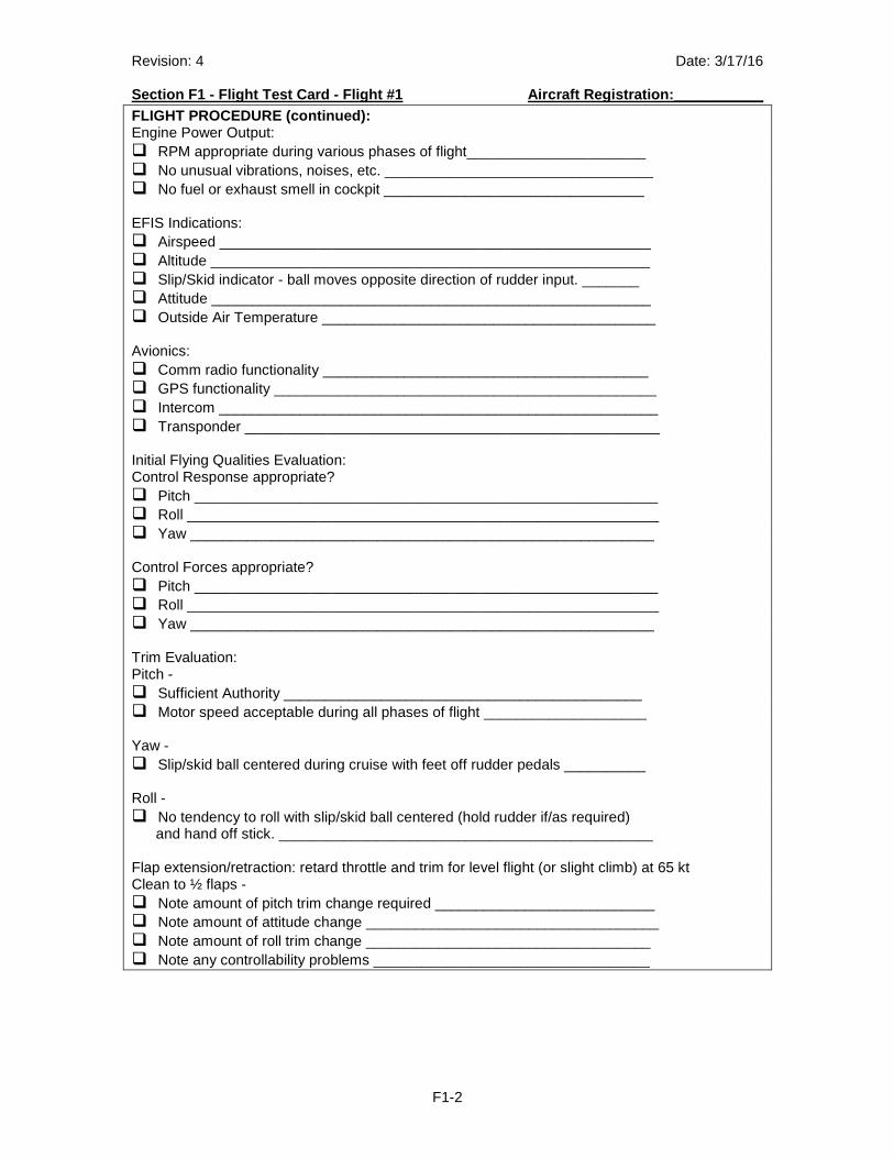
Revision: 4 Date: 3/17/16 Section F1 - Flight Test Card - Flight #1 Aircraft Registration:___________
F1-2
FLIGHT PROCEDURE (continued): Engine Power Output: � RPM appropriate during various phases of flight______________________ � No unusual vibrations, noises, etc. _________________________________ � No fuel or exhaust smell in cockpit ________________________________ EFIS Indications: � Airspeed _____________________________________________________ � Altitude ______________________________________________________ � Slip/Skid indicator - ball moves opposite direction of rudder input. _______ � Attitude ______________________________________________________ � Outside Air Temperature _________________________________________ Avionics: � Comm radio functionality ________________________________________ � GPS functionality _______________________________________________ � Intercom ______________________________________________________ � Transponder ___________________________________________________ Initial Flying Qualities Evaluation: Control Response appropriate? � Pitch _________________________________________________________ � Roll __________________________________________________________ � Yaw _________________________________________________________ Control Forces appropriate? � Pitch _________________________________________________________ � Roll __________________________________________________________ � Yaw _________________________________________________________ Trim Evaluation: Pitch - � Sufficient Authority ____________________________________________ � Motor speed acceptable during all phases of flight ____________________ Yaw - � Slip/skid ball centered during cruise with feet off rudder pedals __________ Roll - � No tendency to roll with slip/skid ball centered (hold rudder if/as required) and hand off stick. ______________________________________________ Flap extension/retraction: retard throttle and trim for level flight (or slight climb) at 65 kt Clean to ½ flaps - � Note amount of pitch trim change required ___________________________ � Note amount of attitude change ____________________________________ � Note amount of roll trim change ___________________________________ � Note any controllability problems __________________________________
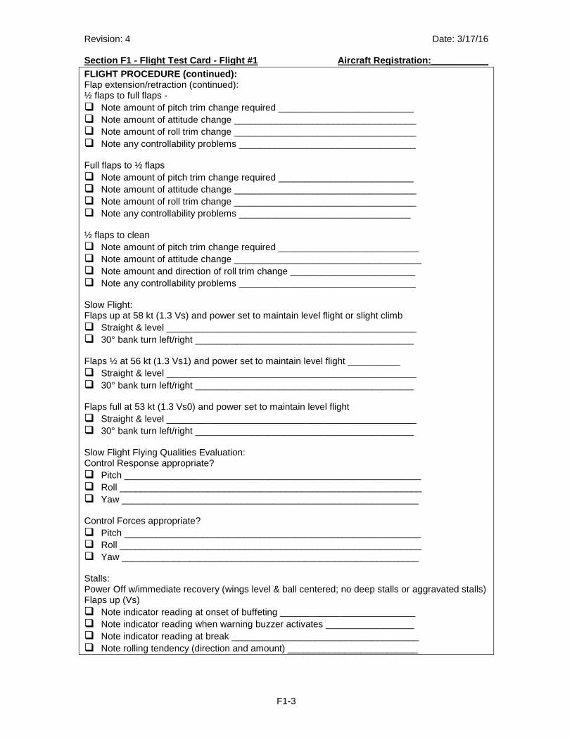
Revision: 4 Date: 3/17/16 Section F1 - Flight Test Card - Flight #1 Aircraft Registration:___________
F1-3
FLIGHT PROCEDURE (continued): Flap extension/retraction (continued): ½ flaps to full flaps - � Note amount of pitch trim change required __________________________ � Note amount of attitude change ___________________________________ � Note amount of roll trim change ___________________________________ � Note any controllability problems __________________________________ Full flaps to ½ flaps � Note amount of pitch trim change required __________________________ � Note amount of attitude change ___________________________________ � Note amount of roll trim change ___________________________________ � Note any controllability problems _________________________________ ½ flaps to clean � Note amount of pitch trim change required ___________________________ � Note amount of attitude change ____________________________________ � Note amount and direction of roll trim change ________________________ � Note any controllability problems __________________________________ Slow Flight: Flaps up at 58 kt (1.3 Vs) and power set to maintain level flight or slight climb � Straight & level ________________________________________________ � 30° bank turn left/right __________________________________________ Flaps ½ at 56 kt (1.3 Vs1) and power set to maintain level flight __________ � Straight & level ________________________________________________ � 30° bank turn left/right __________________________________________ Flaps full at 53 kt (1.3 Vs0) and power set to maintain level flight � Straight & level ________________________________________________ � 30° bank turn left/right __________________________________________ Slow Flight Flying Qualities Evaluation: Control Response appropriate? � Pitch _________________________________________________________ � Roll __________________________________________________________ � Yaw _________________________________________________________ Control Forces appropriate? � Pitch _________________________________________________________ � Roll __________________________________________________________ � Yaw _________________________________________________________ Stalls: Power Off w/immediate recovery (wings level & ball centered; no deep stalls or aggravated stalls) Flaps up (Vs) � Note indicator reading at onset of buffeting __________________________ � Note indicator reading when warning buzzer activates _________________ � Note indicator reading at break ____________________________________ � Note rolling tendency (direction and amount) _________________________
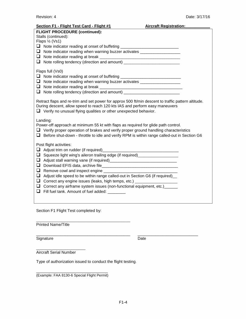
Revision: 4 Date: 3/17/16 Section F1 - Flight Test Card - Flight #1 Aircraft Registration:___________
F1-4
FLIGHT PROCEDURE (continued): Stalls (continued): Flaps ½ (Vs1) � Note indicator reading at onset of buffeting __________________________ � Note indicator reading when warning buzzer activates __________________ � Note indicator reading at break ____________________________________ � Note rolling tendency (direction and amount) _________________________ Flaps full (Vs0) � Note indicator reading at onset of buffeting ___________________________ � Note indicator reading when warning buzzer activates __________________ � Note indicator reading at break _____________________________________ � Note rolling tendency (direction and amount) _________________________ Retract flaps and re-trim and set power for approx 500 ft/min descent to traffic pattern altitude. During descent, allow speed to reach 120 kts IAS and perform easy maneuvers � Verify no unusual flying qualities or other unexpected behavior. Landing: Power-off approach at minimum 55 kt with flaps as required for glide path control. � Verify proper operation of brakes and verify proper ground handling characteristics � Before shut-down - throttle to idle and verify RPM is within range called-out in Section G6 Post flight activities: � Adjust trim on rudder (if required)__________________________________ � Squeeze light wing's aileron trailing edge (if required)__________________ � Adjust stall warning vane (if required)______________________________ � Download EFIS data, archive file__________________________________ � Remove cowl and inspect engine _________________________________ � Adjust idle speed to be within range called-out in Section G6 (if required)__ � Correct any engine issues (leaks, high temps, etc.) ___________________ � Correct any airframe system issues (non-functional equipment, etc.)______ � Fill fuel tank. Amount of fuel added: ________ Section F1 Flight Test completed by: __________________________________________ Printed Name/Title __________________________________________ ___________________________ Signature Date ______________________ Aircraft Serial Number Type of authorization issued to conduct the flight testing.
________________________________ (Example: FAA 8130-6 Special Flight Permit)
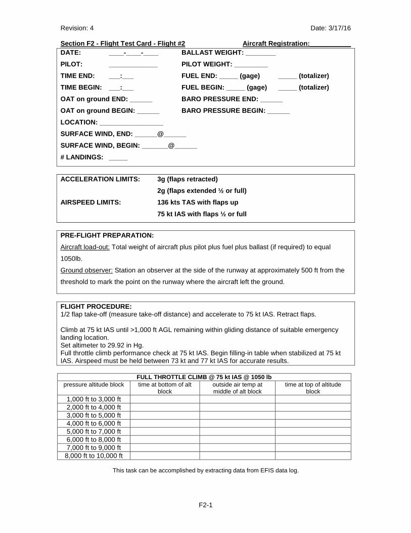
Revision: 4 Date: 3/17/16 Section F2 - Flight Test Card - Flight #2 Aircraft Registration:___________
F2-1
DATE: ____-____-____ BALLAST WEIGHT: ________
PILOT: _____________ PILOT WEIGHT: _________
TIME END: ___:___ FUEL END: _____ (gage) _____ (to talizer)
TIME BEGIN: ___:___ FUEL BEGIN: _____ (gage) _____ (totalizer)
OAT on ground END: ______ BARO PRESSURE END: _____ _
OAT on ground BEGIN: ______ BARO PRESSURE BEGIN: __ ____
LOCATION: _________________
SURFACE WIND, END: ______@______
SURFACE WIND, BEGIN: _______@______
# LANDINGS: _____
ACCELERATION LIMITS: 3g (flaps retracted)
2g (flaps extended ½ or full)
AIRSPEED LIMITS: 136 kts TAS with flaps up
75 kt IAS with flaps ½ or full
PRE-FLIGHT PREPARATION:
Aircraft load-out: Total weight of aircraft plus pilot plus fuel plus ballast (if required) to equal
1050lb.
Ground observer: Station an observer at the side of the runway at approximately 500 ft from the
threshold to mark the point on the runway where the aircraft left the ground.
FLIGHT PROCEDURE: 1/2 flap take-off (measure take-off distance) and accelerate to 75 kt IAS. Retract flaps. Climb at 75 kt IAS until >1,000 ft AGL remaining within gliding distance of suitable emergency landing location. Set altimeter to 29.92 in Hg. Full throttle climb performance check at 75 kt IAS. Begin filling-in table when stabilized at 75 kt IAS. Airspeed must be held between 73 kt and 77 kt IAS for accurate results.
FULL THROTTLE CLIMB @ 75 kt IAS @ 1050 lb pressure altitude block time at bottom of alt
block outside air temp at middle of alt block
time at top of altitude block
1,000 ft to 3,000 ft 2,000 ft to 4,000 ft 3,000 ft to 5,000 ft 4,000 ft to 6,000 ft 5,000 ft to 7,000 ft 6,000 ft to 8,000 ft 7,000 ft to 9,000 ft 8,000 ft to 10,000 ft
This task can be accomplished by extracting data from EFIS data log.
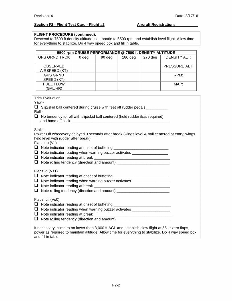
Revision: 4 Date: 3/17/16 Section F2 - Flight Test Card - Flight #2 Aircraft Registration:___________
F2-2
FLIGHT PROCEDURE (continued): Descend to 7500 ft density altitude, set throttle to 5500 rpm and establish level flight. Allow time for everything to stabilize. Do 4 way speed box and fill in table.
5500 rpm CRUISE PERFORMANCE @ 7500 ft DENSITY ALTIT UDE GPS GRND TRCK 0 deg 90 deg 180 deg 270 deg DENSITY ALT:
OBSERVED
AIRSPEED (KT) PRESSURE ALT:
GPS GRND SPEED (KT)
RPM:
FUEL FLOW (GAL/HR)
MAP:
Trim Evaluation: Yaw - � Slip/skid ball centered during cruise with feet off rudder pedals __________ Roll - � No tendency to roll with slip/skid ball centered (hold rudder if/as required) and hand off stick. ______________________________________________ Stalls: Power Off w/recovery delayed 3 seconds after break (wings level & ball centered at entry; wings held level with rudder after break) Flaps up (Vs) � Note indicator reading at onset of buffeting __________________________ � Note indicator reading when warning buzzer activates _________________ � Note indicator reading at break ____________________________________ � Note rolling tendency (direction and amount) _________________________ Flaps ½ (Vs1) � Note indicator reading at onset of buffeting __________________________ � Note indicator reading when warning buzzer activates __________________ � Note indicator reading at break ____________________________________ � Note rolling tendency (direction and amount) _________________________ Flaps full (Vs0) � Note indicator reading at onset of buffeting ___________________________ � Note indicator reading when warning buzzer activates __________________ � Note indicator reading at break _____________________________________ � Note rolling tendency (direction and amount) _________________________ If necessary, climb to no lower than 3,000 ft AGL and establish slow flight at 55 kt zero flaps, power as required to maintain altitude. Allow time for everything to stabilize. Do 4 way speed box and fill in table.
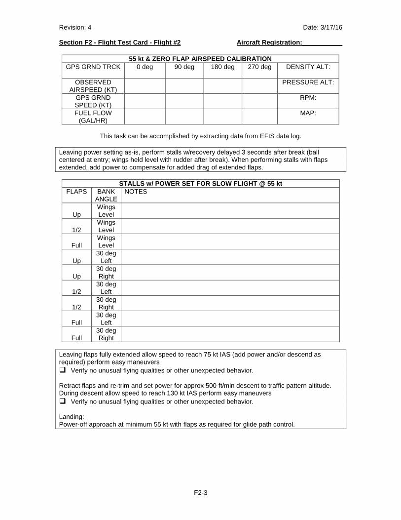
Revision: 4 Date: 3/17/16 Section F2 - Flight Test Card - Flight #2 Aircraft Registration:___________
F2-3
55 kt & ZERO FLAP AIRSPEED CALIBRATION
GPS GRND TRCK 0 deg 90 deg 180 deg 270 deg DENSITY ALT:
OBSERVED AIRSPEED (KT)
PRESSURE ALT:
GPS GRND SPEED (KT)
RPM:
FUEL FLOW (GAL/HR)
MAP:
This task can be accomplished by extracting data from EFIS data log.
Leaving power setting as-is, perform stalls w/recovery delayed 3 seconds after break (ball centered at entry; wings held level with rudder after break). When performing stalls with flaps extended, add power to compensate for added drag of extended flaps.
STALLS w/ POWER SET FOR SLOW FLIGHT @ 55 kt FLAPS BANK
ANGLE NOTES
Up
Wings Level
1/2
Wings Level
Full
Wings Level
Up
30 deg Left
Up
30 deg Right
1/2
30 deg Left
1/2
30 deg Right
Full
30 deg Left
Full
30 deg Right
Leaving flaps fully extended allow speed to reach 75 kt IAS (add power and/or descend as required) perform easy maneuvers � Verify no unusual flying qualities or other unexpected behavior. Retract flaps and re-trim and set power for approx 500 ft/min descent to traffic pattern altitude. During descent allow speed to reach 130 kt IAS perform easy maneuvers � Verify no unusual flying qualities or other unexpected behavior. Landing: Power-off approach at minimum 55 kt with flaps as required for glide path control.
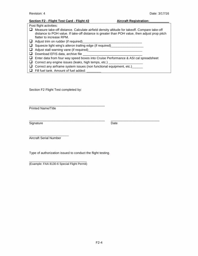
Revision: 4 Date: 3/17/16 Section F2 - Flight Test Card - Flight #2 Aircraft Registration:___________
F2-4
Post flight activities: � Measure take-off distance. Calculate airfield density altitude for takeoff. Compare take-off
distance to POH value. If take-off distance is greater than POH value, then adjust prop pitch flatter to increase RPM.
� Adjust trim on rudder (if required)_________________________________ � Squeeze light wing's aileron trailing edge (if required)__________________ � Adjust stall warning vane (if required)______________________________ � Download EFIS data, archive file _________________________________ � Enter data from four way speed boxes into Cruise Performance & ASI cal spreadsheet � Correct any engine issues (leaks, high temps, etc.) ___________________ � Correct any airframe system issues (non functional equipment, etc.)______ � Fill fuel tank. Amount of fuel added: ________ Section F2 Flight Test completed by: __________________________________________ Printed Name/Title __________________________________________ ___________________________ Signature Date ______________________ Aircraft Serial Number
Type of authorization issued to conduct the flight testing.
________________________________ (Example: FAA 8130-6 Special Flight Permit)
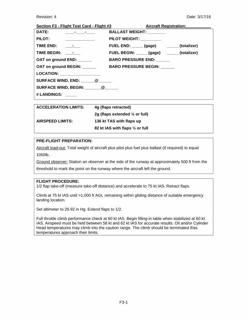
Revision: 4 Date: 3/17/16 Section F3 - Flight Test Card - Flight #3 Aircraft Registration:___________
F3-1
DATE: ____-____-____ BALLAST WEIGHT: ________
PILOT: _____________ PILOT WEIGHT: _________
TIME END: ___:___ FUEL END: _____ (gage) _____ (to talizer)
TIME BEGIN: ___:___ FUEL BEGIN: _____ (gage) _____ (totalizer)
OAT on ground END: ______ BARO PRESSURE END: _____ _
OAT on ground BEGIN: ______ BARO PRESSURE BEGIN: __ ____
LOCATION: __________________
SURFACE WIND, END: ______@______
SURFACE WIND, BEGIN: _______@______
# LANDINGS: _____
ACCELERATION LIMITS: 4g (flaps retracted)
2g (flaps extended ½ or full)
AIRSPEED LIMITS: 136 kt TAS with flaps up
82 kt IAS with flaps ½ or full
PRE-FLIGHT PREPARATION:
Aircraft load-out: Total weight of aircraft plus pilot plus fuel plus ballast (if required) to equal
1050lb.
Ground observer: Station an observer at the side of the runway at approximately 500 ft from the
threshold to mark the point on the runway where the aircraft left the ground.
FLIGHT PROCEDURE: 1/2 flap take-off (measure take-off distance) and accelerate to 75 kt IAS. Retract flaps. Climb at 75 kt IAS until >1,000 ft AGL remaining within gliding distance of suitable emergency landing location. Set altimeter to 29.92 in Hg. Extend flaps to 1/2. Full throttle climb performance check at 60 kt IAS. Begin filling-in table when stabilized at 60 kt IAS. Airspeed must be held between 58 kt and 62 kt IAS for accurate results. Oil and/or Cylinder Head temperatures may climb into the caution range. The climb should be terminated if/as temperatures approach their limits.
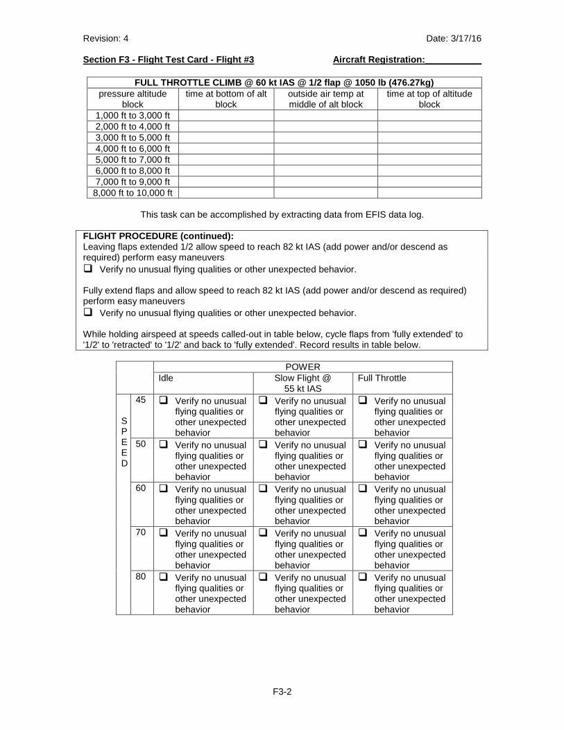
Revision: 4 Date: 3/17/16 Section F3 - Flight Test Card - Flight #3 Aircraft Registration:___________
F3-2
FULL THROTTLE CLIMB @ 60 kt IAS @ 1/2 flap @ 1050 l b (476.27kg)
pressure altitude block
time at bottom of alt block
outside air temp at middle of alt block
time at top of altitude block
1,000 ft to 3,000 ft 2,000 ft to 4,000 ft 3,000 ft to 5,000 ft 4,000 ft to 6,000 ft 5,000 ft to 7,000 ft 6,000 ft to 8,000 ft 7,000 ft to 9,000 ft 8,000 ft to 10,000 ft
This task can be accomplished by extracting data from EFIS data log.
FLIGHT PROCEDURE (continued): Leaving flaps extended 1/2 allow speed to reach 82 kt IAS (add power and/or descend as required) perform easy maneuvers � Verify no unusual flying qualities or other unexpected behavior. Fully extend flaps and allow speed to reach 82 kt IAS (add power and/or descend as required) perform easy maneuvers � Verify no unusual flying qualities or other unexpected behavior. While holding airspeed at speeds called-out in table below, cycle flaps from 'fully extended' to '1/2' to 'retracted' to '1/2' and back to 'fully extended'. Record results in table below.
POWER Idle Slow Flight @
55 kt IAS Full Throttle
SPEED
45 � Verify no unusual flying qualities or other unexpected behavior
� Verify no unusual flying qualities or other unexpected behavior
� Verify no unusual flying qualities or other unexpected behavior
50 � Verify no unusual flying qualities or other unexpected behavior
� Verify no unusual flying qualities or other unexpected behavior
� Verify no unusual flying qualities or other unexpected behavior
60 � Verify no unusual flying qualities or other unexpected behavior
� Verify no unusual flying qualities or other unexpected behavior
� Verify no unusual flying qualities or other unexpected behavior
70 � Verify no unusual flying qualities or other unexpected behavior
� Verify no unusual flying qualities or other unexpected behavior
� Verify no unusual flying qualities or other unexpected behavior
80 � Verify no unusual flying qualities or other unexpected behavior
� Verify no unusual flying qualities or other unexpected behavior
� Verify no unusual flying qualities or other unexpected behavior
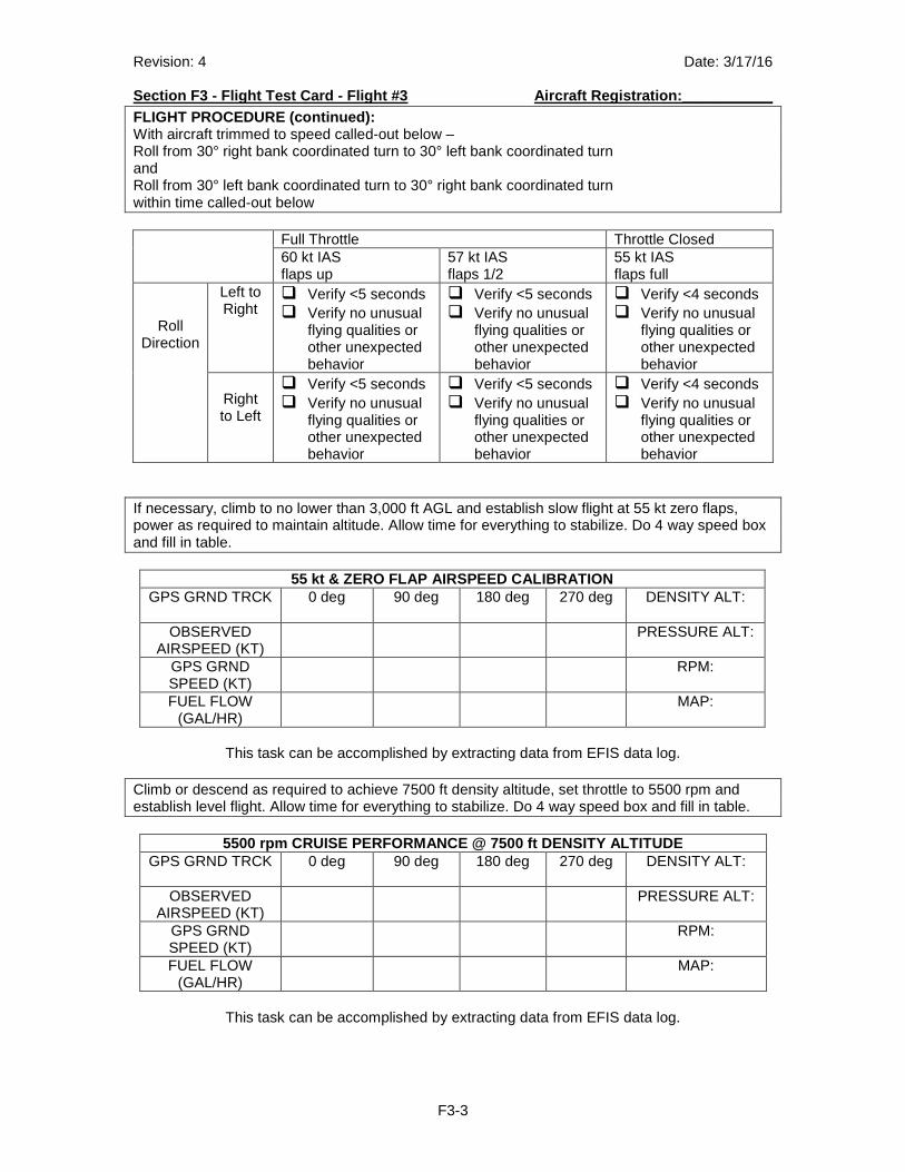
Revision: 4 Date: 3/17/16 Section F3 - Flight Test Card - Flight #3 Aircraft Registration:___________
F3-3
FLIGHT PROCEDURE (continued): With aircraft trimmed to speed called-out below – Roll from 30° right bank coordinated turn to 30° left bank coordinated turn and Roll from 30° left bank coordinated turn to 30° right bank coordinated turn within time called-out below Full Throttle Throttle Closed
60 kt IAS flaps up
57 kt IAS flaps 1/2
55 kt IAS flaps full
Roll Direction
Left to Right
� Verify <5 seconds � Verify no unusual
flying qualities or other unexpected behavior
� Verify <5 seconds � Verify no unusual
flying qualities or other unexpected behavior
� Verify <4 seconds � Verify no unusual
flying qualities or other unexpected behavior
Right to Left
� Verify <5 seconds � Verify no unusual
flying qualities or other unexpected behavior
� Verify <5 seconds � Verify no unusual
flying qualities or other unexpected behavior
� Verify <4 seconds � Verify no unusual
flying qualities or other unexpected behavior
If necessary, climb to no lower than 3,000 ft AGL and establish slow flight at 55 kt zero flaps, power as required to maintain altitude. Allow time for everything to stabilize. Do 4 way speed box and fill in table.
55 kt & ZERO FLAP AIRSPEED CALIBRATION GPS GRND TRCK 0 deg 90 deg 180 deg 270 deg DENSITY ALT:
OBSERVED
AIRSPEED (KT) PRESSURE ALT:
GPS GRND SPEED (KT)
RPM:
FUEL FLOW (GAL/HR)
MAP:
This task can be accomplished by extracting data from EFIS data log.
Climb or descend as required to achieve 7500 ft density altitude, set throttle to 5500 rpm and establish level flight. Allow time for everything to stabilize. Do 4 way speed box and fill in table.
5500 rpm CRUISE PERFORMANCE @ 7500 ft DENSITY ALTIT UDE GPS GRND TRCK 0 deg 90 deg 180 deg 270 deg DENSITY ALT:
OBSERVED
AIRSPEED (KT) PRESSURE ALT:
GPS GRND SPEED (KT)
RPM:
FUEL FLOW (GAL/HR)
MAP:
This task can be accomplished by extracting data from EFIS data log.
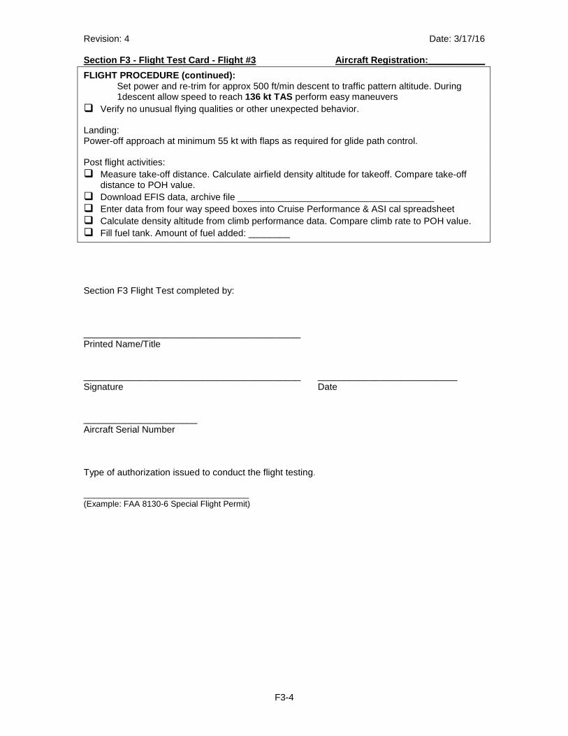
Revision: 4 Date: 3/17/16 Section F3 - Flight Test Card - Flight #3 Aircraft Registration:___________
F3-4
FLIGHT PROCEDURE (continued): Set power and re-trim for approx 500 ft/min descent to traffic pattern altitude. During 1descent allow speed to reach 136 kt TAS perform easy maneuvers � Verify no unusual flying qualities or other unexpected behavior. Landing: Power-off approach at minimum 55 kt with flaps as required for glide path control. Post flight activities: � Measure take-off distance. Calculate airfield density altitude for takeoff. Compare take-off
distance to POH value. � Download EFIS data, archive file ______________________________________ � Enter data from four way speed boxes into Cruise Performance & ASI cal spreadsheet � Calculate density altitude from climb performance data. Compare climb rate to POH value. � Fill fuel tank. Amount of fuel added: ________
Section F3 Flight Test completed by: __________________________________________ Printed Name/Title __________________________________________ ___________________________ Signature Date ______________________ Aircraft Serial Number
Type of authorization issued to conduct the flight testing.
________________________________ (Example: FAA 8130-6 Special Flight Permit)
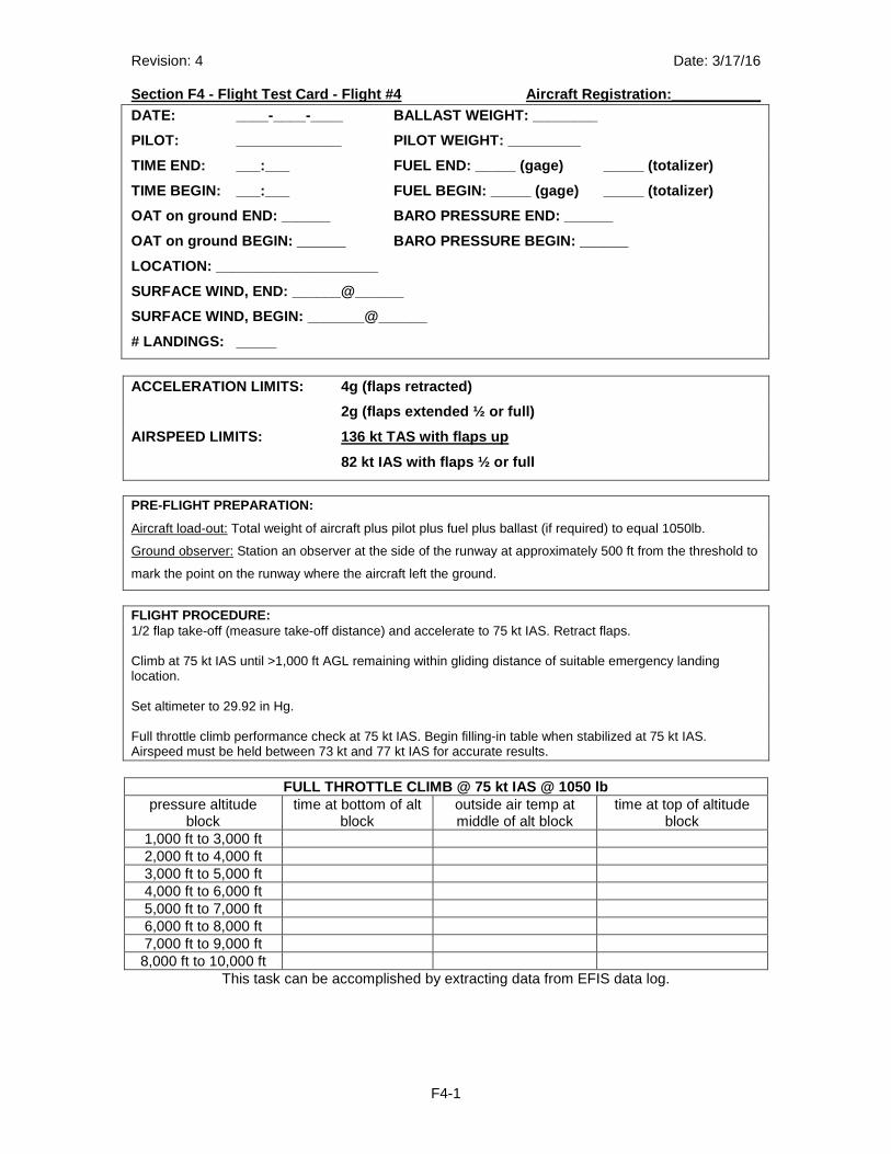
Revision: 4 Date: 3/17/16 Section F4 - Flight Test Card - Flight #4 Aircraft Registration:___________
F4-1
DATE: ____-____-____ BALLAST WEIGHT: ________
PILOT: _____________ PILOT WEIGHT: _________
TIME END: ___:___ FUEL END: _____ (gage) _____ (to talizer)
TIME BEGIN: ___:___ FUEL BEGIN: _____ (gage) _____ (totalizer)
OAT on ground END: ______ BARO PRESSURE END: _____ _
OAT on ground BEGIN: ______ BARO PRESSURE BEGIN: __ ____
LOCATION: ____________________
SURFACE WIND, END: ______@______
SURFACE WIND, BEGIN: _______@______
# LANDINGS: _____
ACCELERATION LIMITS: 4g (flaps retracted)
2g (flaps extended ½ or full)
AIRSPEED LIMITS: 136 kt TAS with flaps up
82 kt IAS with flaps ½ or full
PRE-FLIGHT PREPARATION:
Aircraft load-out: Total weight of aircraft plus pilot plus fuel plus ballast (if required) to equal 1050lb.
Ground observer: Station an observer at the side of the runway at approximately 500 ft from the threshold to
mark the point on the runway where the aircraft left the ground.
FLIGHT PROCEDURE: 1/2 flap take-off (measure take-off distance) and accelerate to 75 kt IAS. Retract flaps. Climb at 75 kt IAS until >1,000 ft AGL remaining within gliding distance of suitable emergency landing location. Set altimeter to 29.92 in Hg. Full throttle climb performance check at 75 kt IAS. Begin filling-in table when stabilized at 75 kt IAS. Airspeed must be held between 73 kt and 77 kt IAS for accurate results.
FULL THROTTLE CLIMB @ 75 kt IAS @ 1050 lb pressure altitude
block time at bottom of alt
block outside air temp at middle of alt block
time at top of altitude block
1,000 ft to 3,000 ft 2,000 ft to 4,000 ft 3,000 ft to 5,000 ft 4,000 ft to 6,000 ft 5,000 ft to 7,000 ft 6,000 ft to 8,000 ft 7,000 ft to 9,000 ft 8,000 ft to 10,000 ft
This task can be accomplished by extracting data from EFIS data log.
Revision: 4 Date: 3/17/16 Section F4 - Flight Test Card - Flight #4 Aircraft Registration:___________
F4-2
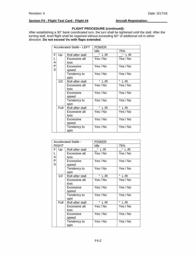
FLIGHT PROCEDURE (continued):
After establishing a 30° bank coordinated turn, the turn shall be tightened until the stall. After the turning stall, level flight shall be regained without exceeding 60° of additional roll in either direction. Do not exceed V fe with flaps extended .
Accelerated Stalls - LEFT POWER Idle 75%
FLAPS
Up Roll after stall ° L /R ° L /R Excessive alt loss
Yes / No Yes / No
Excessive speed
Yes / No Yes / No
Tendency to spin
Yes / No Yes / No
1/2 Roll after stall ° L /R ° L /R Excessive alt loss
Yes / No Yes / No
Excessive speed
Yes / No Yes / No
Tendency to spin
Yes / No Yes / No
Full Roll after stall ° L /R ° L /R Excessive alt loss
Yes / No Yes / No
Excessive speed
Yes / No Yes / No
Tendency to spin
Yes / No Yes / No
Accelerated Stalls - RIGHT
POWER Idle 75%
FLAPS
Up Roll after stall ° L /R ° L /R Excessive alt loss
Yes / No Yes / No
Excessive speed
Yes / No Yes / No
Tendency to spin
Yes / No Yes / No
1/2 Roll after stall ° L /R ° L /R Excessive alt loss
Yes / No Yes / No
Excessive speed
Yes / No Yes / No
Tendency to spin
Yes / No Yes / No
Full Roll after stall ° L /R ° L /R Excessive alt loss
Yes / No Yes / No
Excessive speed
Yes / No Yes / No
Tendency to spin
Yes / No Yes / No
Revision: 4 Date: 3/17/16 Section F4 - Flight Test Card - Flight #4 Aircraft Registration:___________
F4-3
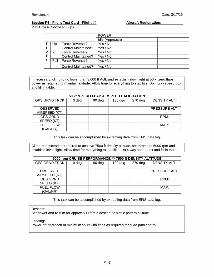
Max Cross-Controlled Slips
POWER Idle (Approach)
FLAPS
Up Force Reversal? Yes / No Control Maintained? Yes / No
½ Force Reversal? Yes / No Control Maintained? Yes / No
Full Force Reversal? Yes / No
Control Maintained? Yes / No If necessary, climb to no lower than 3,000 ft AGL and establish slow flight at 50 kt zero flaps, power as required to maintain altitude. Allow time for everything to stabilize. Do 4 way speed box and fill in table.
50 kt & ZERO FLAP AIRSPEED CALIBRATION GPS GRND TRCK 0 deg 90 deg 180 deg 270 deg DENSITY ALT:
OBSERVED
AIRSPEED (KT) PRESSURE ALT:
GPS GRND SPEED (KT)
RPM:
FUEL FLOW (GAL/HR)
MAP:
This task can be accomplished by extracting data from EFIS data log.
Climb or descend as required to achieve 7500 ft density altitude, set throttle to 5000 rpm and establish level flight. Allow time for everything to stabilize. Do 4 way speed box and fill in table.
5000 rpm CRUISE PERFORMANCE @ 7500 ft DENSITY ALTIT UDE GPS GRND TRCK 0 deg 90 deg 180 deg 270 deg DENSITY ALT:
OBSERVED
AIRSPEED (KT) PRESSURE ALT:
GPS GRND SPEED (KT)
RPM:
FUEL FLOW (GAL/HR)
MAP:
This task can be accomplished by extracting data from EFIS data log.
Descent: Set power and re-trim for approx 500 ft/min descent to traffic pattern altitude. Landing: Power-off approach at minimum 55 kt with flaps as required for glide path control.
Revision: 4 Date: 3/17/16 Section F4 - Flight Test Card - Flight #4 Aircraft Registration:___________
F4-4
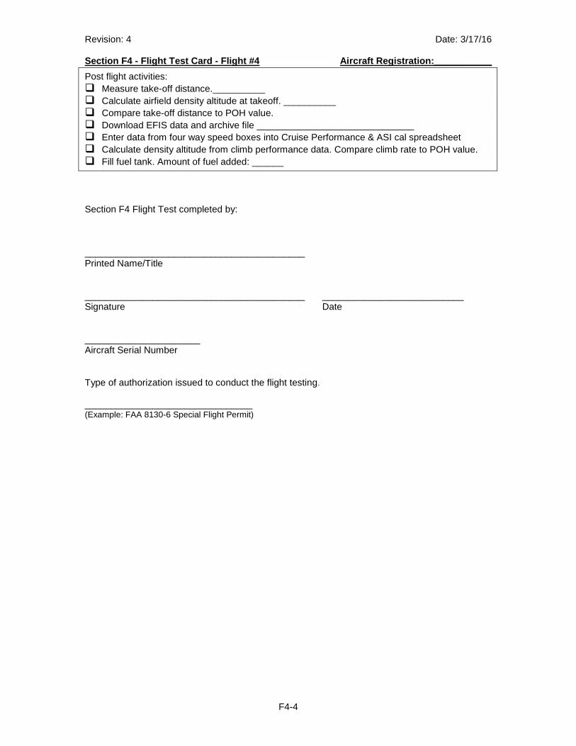
Post flight activities: � Measure take-off distance.__________ � Calculate airfield density altitude at takeoff. __________ � Compare take-off distance to POH value. � Download EFIS data and archive file ______________________________ � Enter data from four way speed boxes into Cruise Performance & ASI cal spreadsheet � Calculate density altitude from climb performance data. Compare climb rate to POH value. � Fill fuel tank. Amount of fuel added: ______
Section F4 Flight Test completed by: __________________________________________ Printed Name/Title __________________________________________ ___________________________ Signature Date ______________________ Aircraft Serial Number Type of authorization issued to conduct the flight testing.
________________________________ (Example: FAA 8130-6 Special Flight Permit)
Revision: 5 Date: 3/17/16 Section F5 - Flight Test Card - Flight #5 Aircraft Registration:___________
F5-1
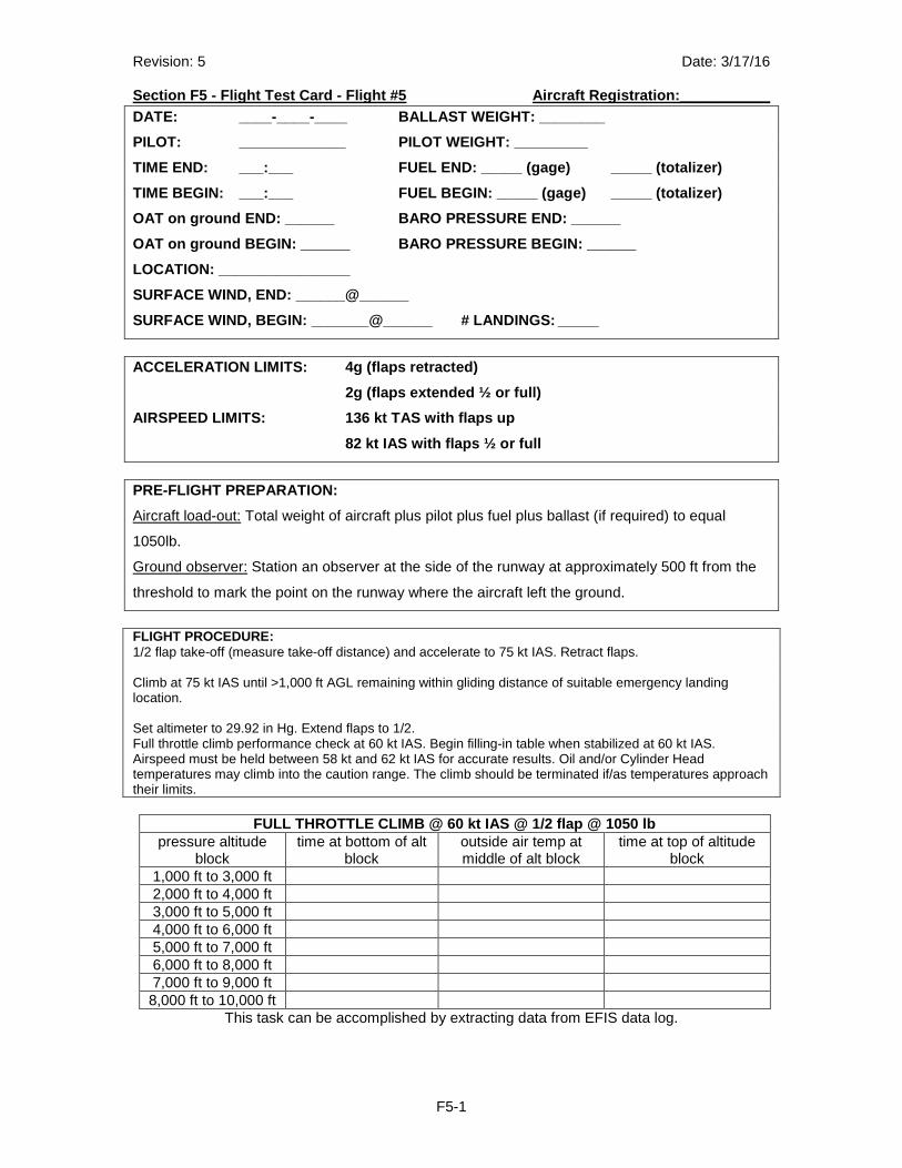
DATE: ____-____-____ BALLAST WEIGHT: ________
PILOT: _____________ PILOT WEIGHT: _________
TIME END: ___:___ FUEL END: _____ (gage) _____ (to talizer)
TIME BEGIN: ___:___ FUEL BEGIN: _____ (gage) _____ (totalizer)
OAT on ground END: ______ BARO PRESSURE END: _____ _
OAT on ground BEGIN: ______ BARO PRESSURE BEGIN: __ ____
LOCATION: ________________
SURFACE WIND, END: ______@______
SURFACE WIND, BEGIN: _______@______ # LANDING S: _____
ACCELERATION LIMITS: 4g (flaps retracted)
2g (flaps extended ½ or full)
AIRSPEED LIMITS: 136 kt TAS with flaps up
82 kt IAS with flaps ½ or full
PRE-FLIGHT PREPARATION:
Aircraft load-out: Total weight of aircraft plus pilot plus fuel plus ballast (if required) to equal
1050lb.
Ground observer: Station an observer at the side of the runway at approximately 500 ft from the
threshold to mark the point on the runway where the aircraft left the ground.
FLIGHT PROCEDURE: 1/2 flap take-off (measure take-off distance) and accelerate to 75 kt IAS. Retract flaps. Climb at 75 kt IAS until >1,000 ft AGL remaining within gliding distance of suitable emergency landing location. Set altimeter to 29.92 in Hg. Extend flaps to 1/2. Full throttle climb performance check at 60 kt IAS. Begin filling-in table when stabilized at 60 kt IAS. Airspeed must be held between 58 kt and 62 kt IAS for accurate results. Oil and/or Cylinder Head temperatures may climb into the caution range. The climb should be terminated if/as temperatures approach their limits.
FULL THROTTLE CLIMB @ 60 kt IAS @ 1/2 flap @ 1050 l b pressure altitude
block time at bottom of alt
block outside air temp at middle of alt block
time at top of altitude block
1,000 ft to 3,000 ft 2,000 ft to 4,000 ft 3,000 ft to 5,000 ft 4,000 ft to 6,000 ft 5,000 ft to 7,000 ft 6,000 ft to 8,000 ft 7,000 ft to 9,000 ft 8,000 ft to 10,000 ft
This task can be accomplished by extracting data from EFIS data log.
Revision: 5 Date: 3/17/16 Section F5 - Flight Test Card - Flight #5 Aircraft Registration:___________
F5-2
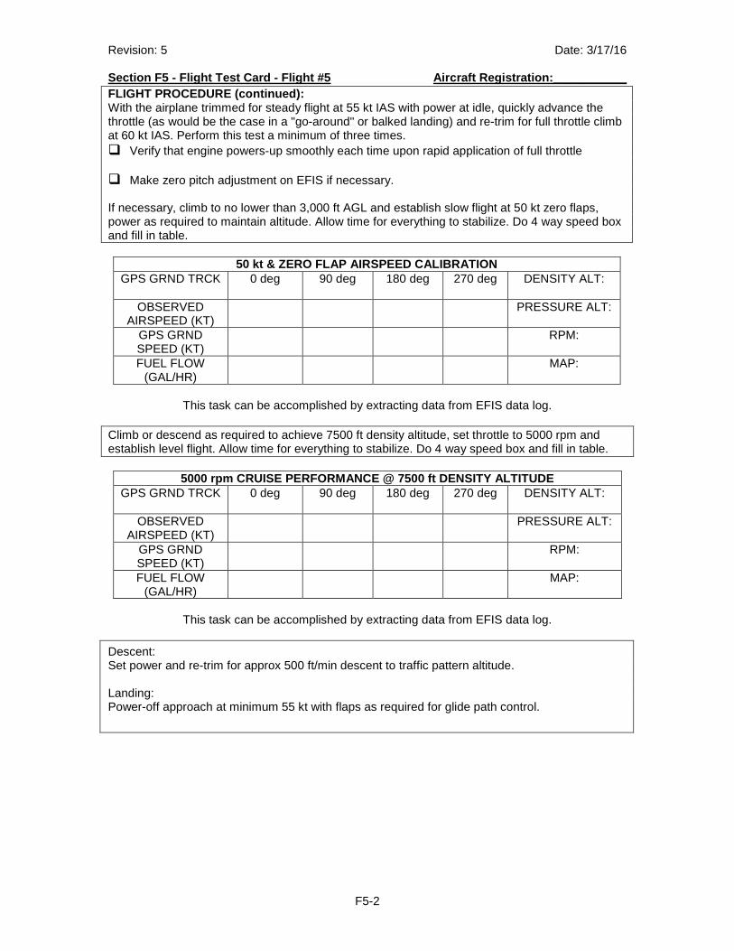
FLIGHT PROCEDURE (continued): With the airplane trimmed for steady flight at 55 kt IAS with power at idle, quickly advance the throttle (as would be the case in a "go-around" or balked landing) and re-trim for full throttle climb at 60 kt IAS. Perform this test a minimum of three times. � Verify that engine powers-up smoothly each time upon rapid application of full throttle � Make zero pitch adjustment on EFIS if necessary. If necessary, climb to no lower than 3,000 ft AGL and establish slow flight at 50 kt zero flaps, power as required to maintain altitude. Allow time for everything to stabilize. Do 4 way speed box and fill in table.
50 kt & ZERO FLAP AIRSPEED CALIBRATION GPS GRND TRCK 0 deg 90 deg 180 deg 270 deg DENSITY ALT:
OBSERVED
AIRSPEED (KT) PRESSURE ALT:
GPS GRND SPEED (KT)
RPM:
FUEL FLOW (GAL/HR)
MAP:
This task can be accomplished by extracting data from EFIS data log.
Climb or descend as required to achieve 7500 ft density altitude, set throttle to 5000 rpm and establish level flight. Allow time for everything to stabilize. Do 4 way speed box and fill in table.
5000 rpm CRUISE PERFORMANCE @ 7500 ft DENSITY ALTIT UDE GPS GRND TRCK 0 deg 90 deg 180 deg 270 deg DENSITY ALT:
OBSERVED
AIRSPEED (KT) PRESSURE ALT:
GPS GRND SPEED (KT)
RPM:
FUEL FLOW (GAL/HR)
MAP:
This task can be accomplished by extracting data from EFIS data log.
Descent: Set power and re-trim for approx 500 ft/min descent to traffic pattern altitude. Landing: Power-off approach at minimum 55 kt with flaps as required for glide path control.
Revision: 5 Date: 3/17/16 Section F5 - Flight Test Card - Flight #5 Aircraft Registration:___________
F5-3
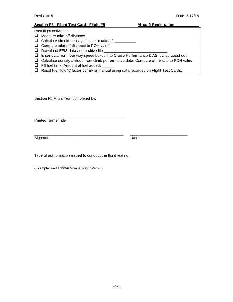
Post flight activities: � Measure take-off distance.__________ � Calculate airfield density altitude at takeoff. __________ � Compare take-off distance to POH value. � Download EFIS data and archive file ______________________________ � Enter data from four way speed boxes into Cruise Performance & ASI cal spreadsheet � Calculate density altitude from climb performance data. Compare climb rate to POH value. � Fill fuel tank. Amount of fuel added: _____ � Reset fuel flow 'k' factor per EFIS manual using data recorded on Flight Test Cards.
Section F5 Flight Test completed by: __________________________________________ Printed Name/Title __________________________________________ ___________________________ Signature Date Type of authorization issued to conduct the flight testing.
________________________________ (Example: FAA 8130-6 Special Flight Permit)
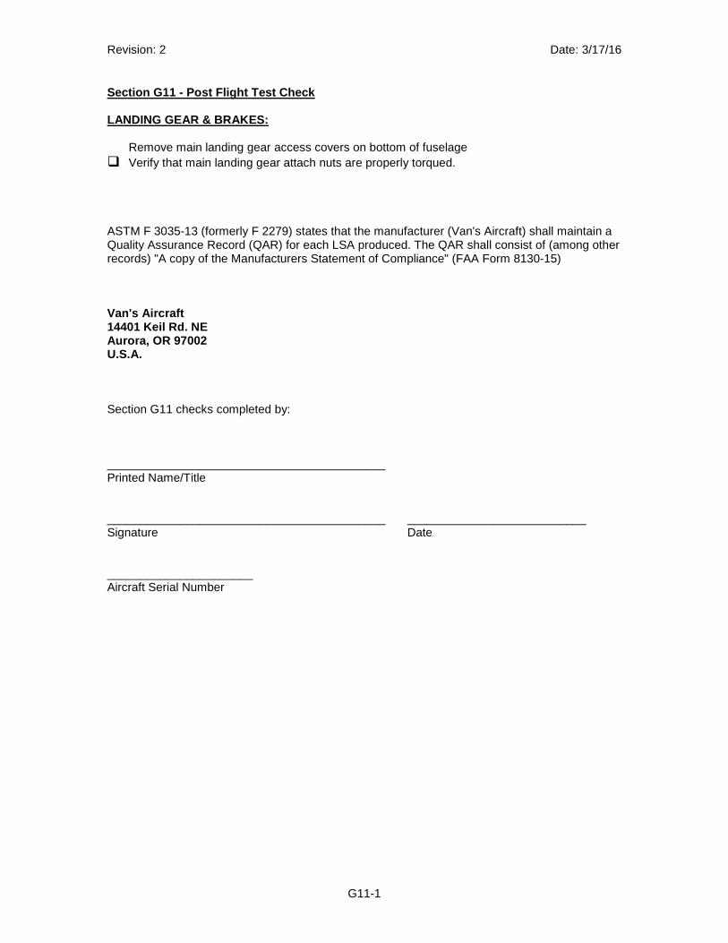
Revision: 2 Date: 3/17/16
G11-1
Section G11 - Post Flight Test Check LANDING GEAR & BRAKES:
Remove main landing gear access covers on bottom of fuselage � Verify that main landing gear attach nuts are properly torqued. ASTM F 3035-13 (formerly F 2279) states that the manufacturer (Van's Aircraft) shall maintain a Quality Assurance Record (QAR) for each LSA produced. The QAR shall consist of (among other records) "A copy of the Manufacturers Statement of Compliance" (FAA Form 8130-15) Van's Aircraft 14401 Keil Rd. NE Aurora, OR 97002 U.S.A. Section G11 checks completed by: __________________________________________ Printed Name/Title __________________________________________ ___________________________ Signature Date ______________________ Aircraft Serial Number