Embed Size (px)
Citation preview
Russian 2S1 Self-Propelled Howitzer, "Gvozdika", Part 1 (Revised
February 7, 2001)
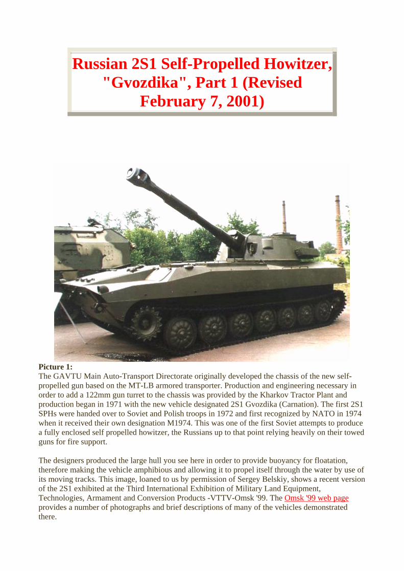
Picture 1: The GAVTU Main Auto-Transport Directorate originally developed the chassis of the new self-propelled gun based on the MT-LB armored transporter. Production and engineering necessary in order to add a 122mm gun turret to the chassis was provided by the Kharkov Tractor Plant and production began in 1971 with the new vehicle designated 2S1 Gvozdika (Carnation). The first 2S1 SPHs were handed over to Soviet and Polish troops in 1972 and first recognized by NATO in 1974 when it received their own designation M1974. This was one of the first Soviet attempts to produce a fully enclosed self propelled howitzer, the Russians up to that point relying heavily on their towed guns for fire support. The designers produced the large hull you see here in order to provide buoyancy for floatation, therefore making the vehicle amphibious and allowing it to propel itself through the water by use of its moving tracks. This image, loaned to us by permission of Sergey Belskiy, shows a recent version of the 2S1 exhibited at the Third International Exhibition of Military Land Equipment, Technologies, Armament and Conversion Products -VTTV-Omsk '99. The Omsk '99 web page provides a number of photographs and brief descriptions of many of the vehicles demonstrated there.
This Part 1 will examine the turret and fighting compartment of the 2S1 and Part 2 will continue with the turret and then move on to the driver's area and power plant.
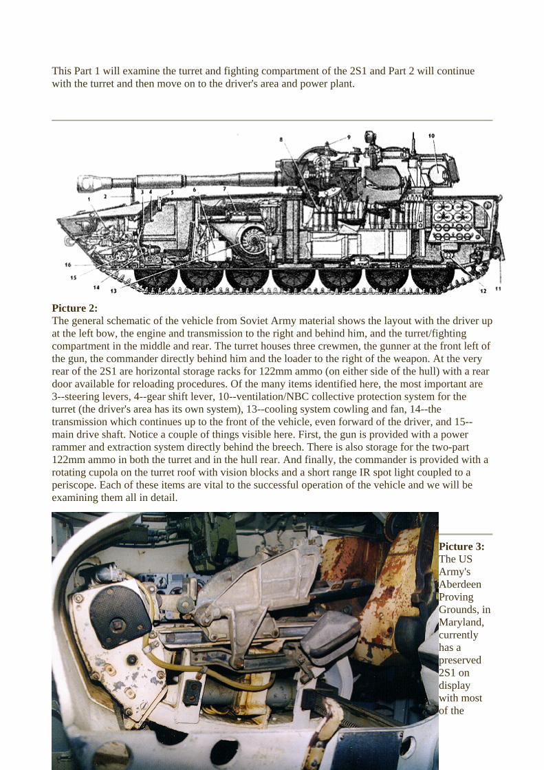
Picture 2: The general schematic of the vehicle from Soviet Army material shows the layout with the driver up at the left bow, the engine and transmission to the right and behind him, and the turret/fighting compartment in the middle and rear. The turret houses three crewmen, the gunner at the front left of the gun, the commander directly behind him and the loader to the right of the weapon. At the very rear of the 2S1 are horizontal storage racks for 122mm ammo (on either side of the hull) with a rear door available for reloading procedures. Of the many items identified here, the most important are 3--steering levers, 4--gear shift lever, 10--ventilation/NBC collective protection system for the turret (the driver's area has its own system), 13--cooling system cowling and fan, 14--the transmission which continues up to the front of the vehicle, even forward of the driver, and 15--main drive shaft. Notice a couple of things visible here. First, the gun is provided with a power rammer and extraction system directly behind the breech. There is also storage for the two-part 122mm ammo in both the turret and in the hull rear. And finally, the commander is provided with a rotating cupola on the turret roof with vision blocks and a short range IR spot light coupled to a periscope. Each of these items are vital to the successful operation of the vehicle and we will be examining them all in detail.
Picture 3: The US Army's Aberdeen Proving Grounds, in Maryland, currently has a preserved 2S1 on display with most of the
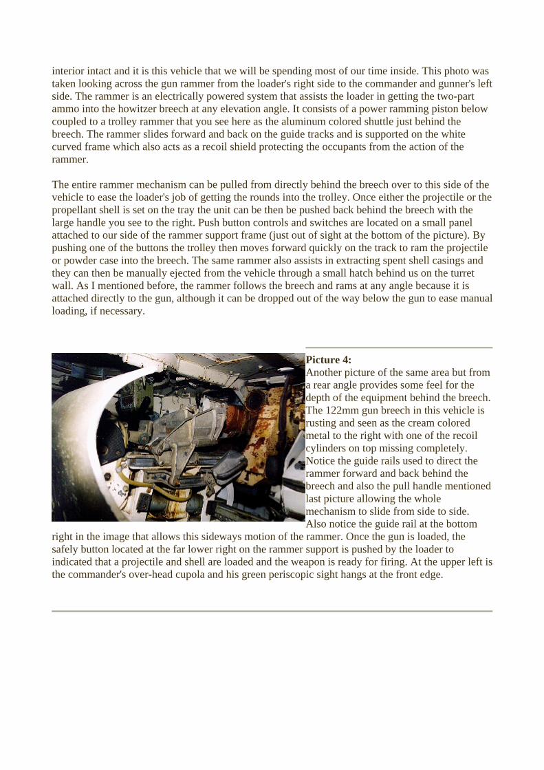
interior intact and it is this vehicle that we will be spending most of our time inside. This photo was taken looking across the gun rammer from the loader's right side to the commander and gunner's left side. The rammer is an electrically powered system that assists the loader in getting the two-part ammo into the howitzer breech at any elevation angle. It consists of a power ramming piston below coupled to a trolley rammer that you see here as the aluminum colored shuttle just behind the breech. The rammer slides forward and back on the guide tracks and is supported on the white curved frame which also acts as a recoil shield protecting the occupants from the action of the rammer. The entire rammer mechanism can be pulled from directly behind the breech over to this side of the vehicle to ease the loader's job of getting the rounds into the trolley. Once either the projectile or the propellant shell is set on the tray the unit can be then be pushed back behind the breech with the large handle you see to the right. Push button controls and switches are located on a small panel attached to our side of the rammer support frame (just out of sight at the bottom of the picture). By pushing one of the buttons the trolley then moves forward quickly on the track to ram the projectile or powder case into the breech. The same rammer also assists in extracting spent shell casings and they can then be manually ejected from the vehicle through a small hatch behind us on the turret wall. As I mentioned before, the rammer follows the breech and rams at any angle because it is attached directly to the gun, although it can be dropped out of the way below the gun to ease manual loading, if necessary.
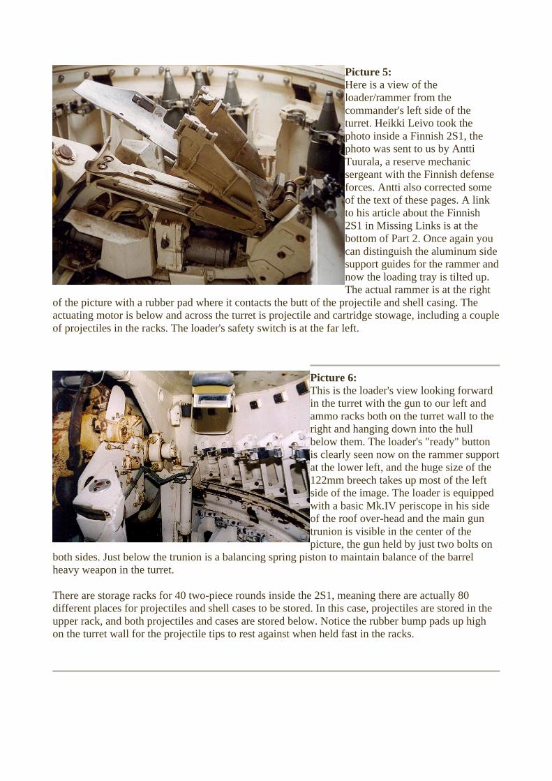
Picture 4: Another picture of the same area but from a rear angle provides some feel for the depth of the equipment behind the breech. The 122mm gun breech in this vehicle is rusting and seen as the cream colored metal to the right with one of the recoil cylinders on top missing completely. Notice the guide rails used to direct the rammer forward and back behind the breech and also the pull handle mentioned last picture allowing the whole mechanism to slide from side to side. Also notice the guide rail at the bottom
right in the image that allows this sideways motion of the rammer. Once the gun is loaded, the safely button located at the far lower right on the rammer support is pushed by the loader to indicated that a projectile and shell are loaded and the weapon is ready for firing. At the upper left is the commander's over-head cupola and his green periscopic sight hangs at the front edge.
Picture 5: Here is a view of the loader/rammer from the commander's left side of the turret. Heikki Leivo took the photo inside a Finnish 2S1, the photo was sent to us by Antti Tuurala, a reserve mechanic sergeant with the Finnish defense forces. Antti also corrected some of the text of these pages. A link to his article about the Finnish 2S1 in Missing Links is at the bottom of Part 2. Once again you can distinguish the aluminum side support guides for the rammer anow the loading tray is tilted up. The actual rammer is at the right
of the picture with a rubber pad where it contacts the butt of the projectile and shell casing. The actuating motor is below and across the turret is projectile and cartridge stowage, including a coupof projectiles in the racks. The loader's safety switch is at the far left.
nd
le
Picture 6: This is the loader's view looking forward in the turret with the gun to our left and ammo racks both on the turret wall to the right and hanging down into the hull below them. The loader's "ready" button is clearly seen now on the rammer sat the lower left, and the huge size of th122mm breech takes up most of the left side of the image. The loader is equipped with a basic Mk.IV periscope in his side of the roof over-head and the main guntrunion is visible in the center of the picture, the gun held by just two bolts on
both sides. Just below the trunion is a balancing spring piston to maintain balance of the barrel heavy weapon in the turret. There are storage racks for 40 two-piece rounds inside the 2S1, meaning there are actually 80 different places for projectiles and shell cases to be stored. In this case, projectiles are stored in the upper rack, and both projectiles and cases are stored below. Notice the rubber bump pads up high on the turret wall for the projectile tips to rest against when held fast in the racks.
upport e

Picture 7: This photo is taken of the same general area, but closer to the balance cylinder. The turret is rotated forward and the open panel on the wall below the gun is an access plate for the engine compartment just forward of the turret area. Although the upper turret ammo racks can only hone projectile, many of the lower hanginracks are deep enough for two cases. Allthe moving mechanisms in the turret are electrically or manually powered. TSoviets typically do not use hydraulics in their AFVs.
At the upper left is the gunner's white manual elevation and black traverse hand wheels. His elevated seat is directly behind the controls, in this case with the seat back folded forward. There is a full turret basket floor and the elevated gunner's seat has its own elevated floor directly in front of the seat. Down below the seat and footrest at the lower left of the picture you can just see part of the crew heater as the shiny cylinder in the shadows.
old g
he
Picture 8: Another view of the loader's side of the turret shows the racks at the right and rear of the turret. A support for a folding seat hangs at the bottom of the picture and the side of the rammer support is at the far right.
Picture 9: The upper portion of the right and rear of the right side of the turret are seen here, with the open (actually missing) shell ejection hatch at the left. The yellow object hanging at the upper left is the bof the loader's periscope we saw previously and now the ammo racks in tback of the turret are visible. There are racks on both this right side of the bustland directly behind the gun, but there is no ammo stored behind the comman
ack
he
e
der's
side because the powered ventilator with the NBC system is over there. Although it is just out of view, the loader has a roof hatch over his position. Notice the slightly different sizes of rack positions for the five smaller projectiles and eight larger charges in this rack.
Picture 10: This is the view looking back out the rear of the hull, through the ammo storage aand toward the rear hull door. Racks take up both sides of this area with storageight projectiles and eight charges on eside. There are hull roof stiffeners at both sides of the rear door with grab handles above and to the sides. Under most firing circumstances the four man 2S1 crew are augmented by at least two additional loaders outside the vehicle. Ammo is loaded through this back door and onto anadjustable trough to be pushed to the
in the turret. Notice the darker gray green paint color of the floor in contrast to the white of the remainder of the vehicle. The rear door has a pistol port, although there is no viewing port for aiming the SMG; two latches at the left secure the door. At the upper right is the commander's seathere it has been folded down, and his periscope storage bin is seen under the seat support.
rea
e for ach
crew
,
Picture 11:
eapon in the 2S1 is a d
s
1 the
-automatic d
he
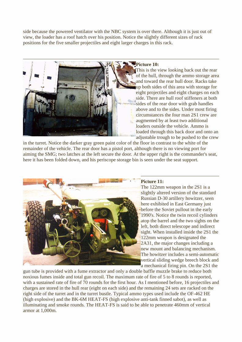
The 122mm wslightly altered version of the standarRussian D-30 artillery howitzer, seen here exhibited in East Germany just before the Soviet pullout in the early 1990's. Notice the twin recoil cylinderatop the barrel and the two sights on the left, both direct telescope and indirectsight. When installed inside the 2S122mm weapon is designated the 2A31, the major changes including a new mount and balancing mechanism. The howitzer includes a semivertical sliding wedge breech block ana mechanical firing pin. On the 2S1 the e baffle muzzle brake to reduce both
noxious fumes inside and total gun recoil. The maximum rate of fire of 5 to 8 rounds is reported,with a sustained rate of fire of 70 rounds for the first hour. As I mentioned before, 16 projectiles andcharges are stored in the hull rear (eight on each side) and the remaining 24 sets are racked on tright side of the turret and in the turret bustle. Typical ammo types used include the OF-462 HE (high explosive) and the BK-6M HEAT-FS (high explosive anti-tank finned sabot), as well as illuminating and smoke rounds. The HEAT-FS is said to be able to penetrate 460mm of vertical armor at 1,000m.
gun tube is provided with a fume extractor and only a doubl

Tsimilar to the Krasnopol fired by the 152mm 2S19, covered elsewhere in AFV INTERIORS. The Kitolov-2 has a maximum range of 12,000m and weighs 25kg complete. Once fired in the general direction of the target (typically a tank) a laser designator directed by others illuminates the target, allowing the Kitolov-2 to direct its flight during final descent onto target. This concludes Part 1 of our exploration of the Russian 2S1 self-propelled howitzer.
he 122mm howitzer can also fire the recently produced Kitolov-2 laser-guided projectile that is
TO RUSSIAN 2S1 SPH PART 2
ACK TO AFV INTERIORS HOME PAGE B
(c) 2001, 2003 AFV INTERIORS Web Magazine
Russian 2S1 Self-Propelled Howitzer, "Gvozdika", Part 2 (Revised
February 7, 2001)
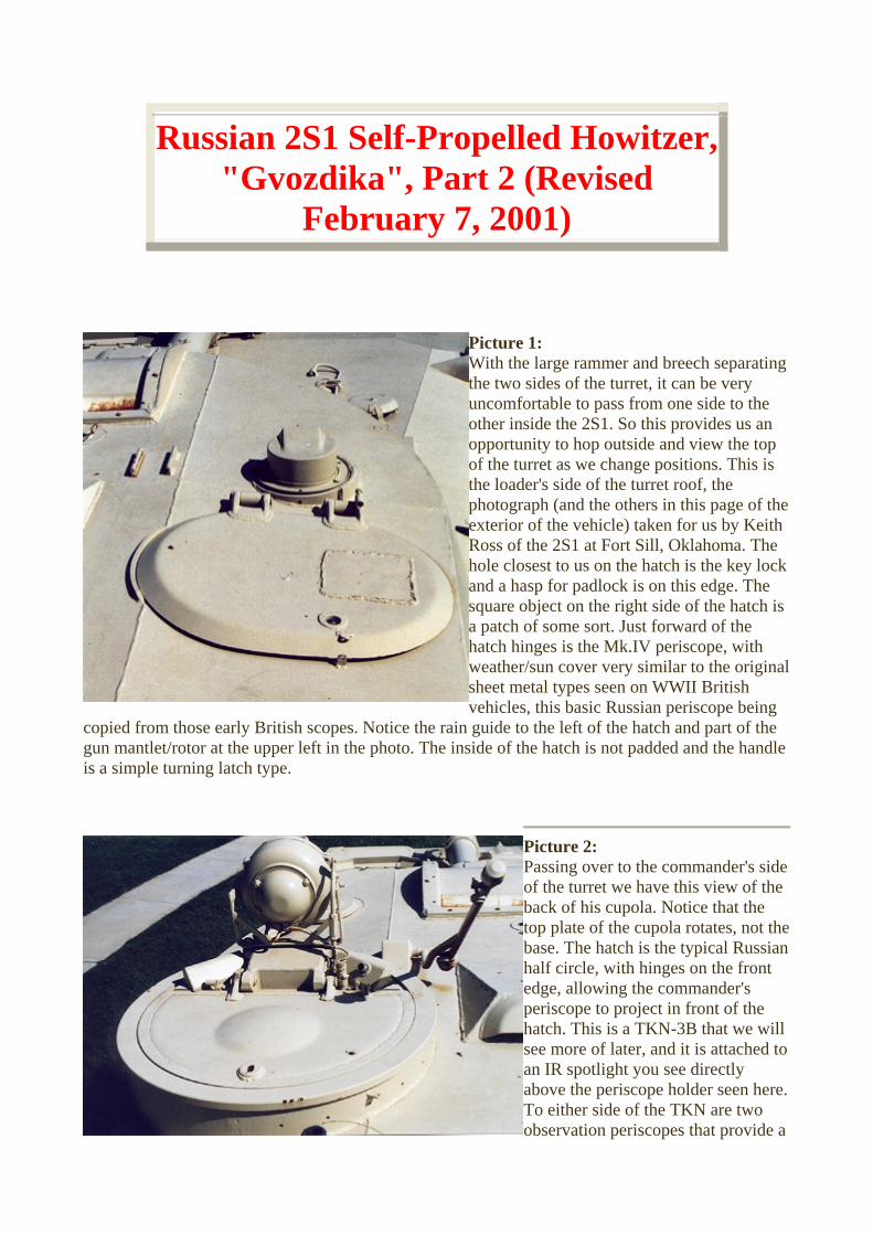
Picture 1: With the large rammer and breech separating the two sides of the turret, it can be very uncomfortable to pass from one side to the other inside the 2S1. So this provides us an opportunity to hop outside and view the top of the turret as we change positions. This is the loader's side of the turret roof, the photograph (and the others in this page of texterior of the vehicle) taken for us by KeitRoss of the 2S1 at Fort Sill, Oklahohole closest to us on the hatch is the key land a hasp for padlock is on this edge. The square object on the right side of the hatcha patch of some sort. Just forward of the hatch hinges is the Mk.IV periscope, with weather/sun cover very similar to the originsheet metal types seen on WWII British vehicles, this basic Russian periscope being
copied from those early British scopes. Notice the rain guide to the left of the hatch and part of the gun mantlet/rotor at the upper left in the photo. The inside of the hatch is not padded and the handleis a simple turning latch type.
he h
ma. The ock
is
al
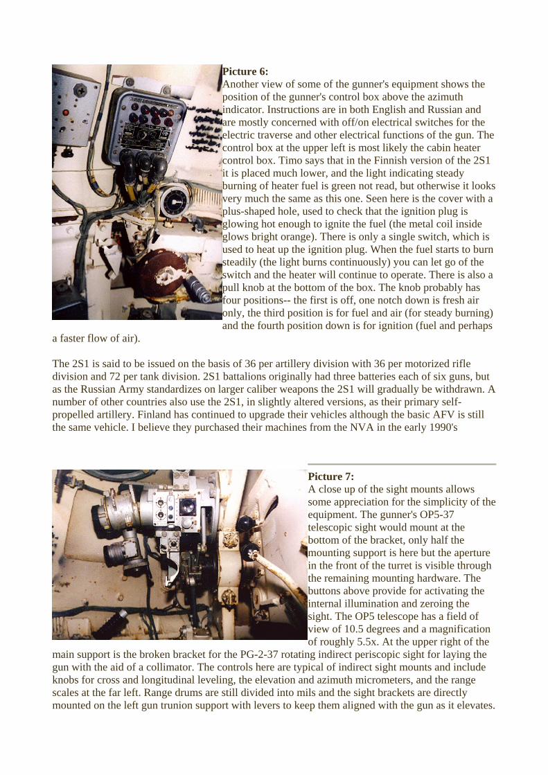
Picture 2: Passing over to the commander's side of the turret we have this view of the back of his cupola. Notice that the top plate of the cupola rotates, not tbase. The hatch is the typical Russhalf circle, with hinges on the front edge, allowing the commandperiscope to project in front of the hatch. This is a TKN-3B that we will see more of later, and it is attached toan IR spotlight you see directly above the periscope holder seen hereTo either side of the TKN are two observation periscopes that provide a
he ian
er's
.

combined field of view of around 70 degrees. Notice the opening in the roof at the right for the ceiling exhaust fan. The small round hatch, forward of the commander's cupola, is for the gunner's indirect fire sight to protrude out the top of the roof. The sight is missing and the hatch is closed in this photo.
Picture 3: This is what is left of the TKN-3B periscope in the Aberdeen vehicle we saw in Part 1. The right ocular is missing as well as the front cover plate, but the black control handles on both sides of the green painted periscope body are still intact. As you may recall, this is a passive day night periscope with an interesting additional feature. There is a mechanical sensor in the rotating cupola that can determine the directing the cupola/periscope is pointing in relationship to the turret. When the commander has found a new target in his
periscope's binocular sights he can push the buttons on the end of the handles and the turret will automatically traverse in the new direction. A similar commander's sight is mounted in a number of Soviet/Russian AFVs, allowing a type of hunter/killer relationship between the commander and gunner. As you may be able to tell from the photograph, the periscope is heated to reduce condensation and so are the flanking vision periscopes. Also visible in this photo is the vehicle radio--what appears to be the typical R-123 transceiver. It is a FM set with a frequency range of 20 to 51.5 MC and it can be continually tuned over the entire frequency range. There is also a switch that allows the operator to select any one of four pre-set frequencies. There are two antennas matched to the set, one a four meter whip for when the vehicle is in motion and the other a ten meter telescopic antenna for use when the vehicle is used as a stationary battery. The R-123M version (like this) has no internal speaker and a headset/mike or CVC type helmet must be used. Also visible on this left side of the turret is the gunner's electrical gun control box to the lower right of the TKN, the azimuth indicator to the lower right of that, and part of the gunner's indirect sight mount at the far right. Notice the indirect sight's roof opening above the sight mount. The black Arabic stencil writing to the right of the gun control box reminds the gunner to unlock the howitzer tube support before traversing the turret. As you will find inside most Russian export vehicles, the instruction plates are written in both Russian (Cyrillic) and English.
Picture 4: This is the view from the floor under the commander's seat looking up. You can now better see the TKN periscope rangefinder and the two flanking periscopes as well. Notice the latches to either side of the periscopes for releasing them in order to replace the glass viewing

blocks. The TKN can also be unlatched and removed for repairs or placed in stowage in a box directly under the commander's seat. To the left is the radio, and the indirect sight mount (with over-head roof opening) is seen at the bottom of the photo. At the right is the rammer support with only part of the rusting breech ring visible at the lower right.
Picture 5: These are the gunner's controls at the forward left edge of the turret. The elevation hand wheel is at the right and the traverse wheel is a bit more rusted at the left. The trigger for the main gun is situated at the front of the elevation wheel handle (the thick part). We have seen the azimuth indicator in a previous picture and here you can see that it is indicating the turret is pointing just about directly forward (0 degrees). To the right of the indicator is a black rubber hand grip of no other purpose than to steady the gunner in
his seat, and below it and the turret ring is part of the electric motor for traversing the turret by the gunner or by the commander's TKN. The gunner does have power traverse, but the mechanism is mostly hidden in this picture. Timo Räsänen, an ex 2S1 Finnish Army gunner, recalls that they didn't use the power traverse very often in training. In fact, he remembers using it only once, just to test it to see if it actually worked! This was because most shoots were indirect artillery support, and in that case the manual controls were the only ones necessary. However, powered traverse was not very quick, and it didn't stop automatically unless the tube hit something heavy. The gunner is almost totally blind inside the turret during traverse, as both the direct sight and periscope are oriented away from the vehicle. It is possible for the tube to hit the open driver's hatch or rip off the air filters from the right hand side of the hull and, of course, K.O. any unwary crew members in the vicinity. The power traverse is a lifesaver if the gunner needs to shoot at a fast-moving target with direct sights, but otherwise he can manage just fine without it. To use the power traverse, you start by rotating the manual traverse hand wheel in the direction you want to turn the turret and then press the power button down on the wheel- the electric traverse motor then takes over. Timo recalls that to stop the traverse, he just needed to release the button. The motor also stops by itself when the gun rotates to the centered position (pointing straight ahead), which is handy when it is time to secure it in place with the external gun support next to the driver's hatch. Just as the turret traverse gearbox is attached to the hand traverse and the electric motor, the elevation wheel is directly attached to the elevation gearbox behind it with a pinion under the gun support. The other gray/silver boxes you see on the turret basket floor are electrical boxes for turret controls and the radio.
Picture 6: Another view of some of the gunner's equipment shows the position of the gunner's control box above the azimuth indicator. Instructions are in both English and Russian and are mostly concerned with off/on electrical switches for the electric traverse and other electrical functions of the gun. The control box at the upper left is most likely the cabin heater control box. Timo says that in the Finnish version of the 2S1 it is placed much lower, and the light indicating steady burning of heater fuel is green not read, but otherwise it lvery much the same as this one. Seen here is the cover with a plus-shaped hole, used to check that the ignition plug is glowing hot enough to ignite the fuel (the metal coil inside glows bright orange). There is only a single switch, which is used to heat up the ignition plug. When the fuel starts to burn steadily (the light burns continuously) you can let go of the switch and the heater will continue to operate. There is also a pull knob at the bottom of the box. The knob probably has four positions-- the first is off, one notch down is fresh air only, the third position is for fuel and air (for steady burning) and the fourth position down is for ignition (fuel and perhaps
a faster flow of air). The 2S1 is said to be issued on the basis of 36 per artillery division with 36 per motorized rifle division and 72 per tank division. 2S1 battalions originally had three batteries each of six guns, but as the Russian Army standardizes on larger caliber weapons the 2S1 will gradually be withdrawn. A number of other countries also use the 2S1, in slightly altered versions, as their primary self-propelled artillery. Finland has continued to upgrade their vehicles although the basic AFV is still the same vehicle. I believe they purchased their machines from the NVA in the early 1990's
ooks
Picture 7: A close up of the sight mounts allows some appreciation for the simplicity of tequipment. The gunner's OP5-37 telescopic sight would mount at the bottom of the bracket, only half the mounting support is here but the aperture in the front of the turret is visible through the remaining mounting hardware. The buttons above provide for activating the internal illumination and zeroing the sight. The OP5 telescope has a field of view of 10.5 degrees and a magnification of roughly 5.5x. At the upper right of the
main support is the broken bracket for the PG-2-37 rotating indirect periscopic sight for laying the gun with the aid of a collimator. The controls here are typical of indirect sight mounts and include knobs for cross and longitudinal leveling, the elevation and azimuth micrometers, and the range scales at the far left. Range drums are still divided into mils and the sight brackets are directly mounted on the left gun trunion support with levers to keep them aligned with the gun as it elevates.
he

The PG-2 has similar characteristics to the OP5, a field of view of 10.5 degrees and a magnification of 5.5x. A couple of the 122mm gun's control levers with black knobs are at the right and the gunner's hand support is seen again at the lower left. The hatch over the indirect sight is opened by a simple handle, which allows the periscope to protrude up and outside the turret. Part of the handle is visible at the upper left along with the round hatch itself, here seen in the closed position. Notice how a part of the turret had to be removed and extended to make room for the sight mount. This small extension can be seen easily in the introductory photo of the exterior of the vehicle (Part 1).
Picture 8: Another of Heikki Leivo's photos inside a Finnish 2S1 shows how the sights appear when mounted inside an active vehicle. Again, the photo was sent to us by Antti Tuurala. This time the complete gunner's OP5-37 telescopic sight can be seen as well as the PG-2-37 rotating indirect periscopic sight to the left. Oculars fboth sights are surrounded with blacpadding to protect the gunner's face. Once again, the gun's trunions and thcastle nuts that hold the gun in place are at the right and the opening afront of the turret for the telescopic sight can be seen between the twsight bodies. If you look closely you can see the index scales on the range drum to the left of the indirect sight.
AThe switches are for turning on the lights and the heating mechanisms of the sights. The two blacknobs in the left and right upper corners are used to align the indirect periscope exactly horizontally. To do this you used the bubble levels, adjusting the sight mount so the bubin the center of their glass tube (the same technique as used in carpenters' levels). One of these levels is just above the forehead padding, and the other is located on the left side of the periscop(black rectangles). The photo is a bit blurry so you can barely see the level's glass tube. The smalleshiny metal knobs are used to set the periscope to the given values for the target. The scales are visible in two small windows, and all three indicator "traffic lights" are lit only when the gun is exactly at the wanted elevation. Timo believes that the black knob at the end of the cylinder withgrooves (lower left) is for adjusting for elevation difference between the howitzer's location and thtarget's altitude. This was probably useful when in the mountains, but since Finland is pretty flat country he usually had his elevation set to zero for both the vehicle and target. Abelow the elevation "screen", is just a cover for the sight graticle light bulb. On a lighter note, notthe thin metal handle just below the sights? That's the windshield wiper for the exterior protective glass cover. Timo says this high-tech, state-of-the-art mechanism is operated by hand- or it would have been if he ever saw one that actually worked!
or k
e
t the
o
gain, Timo has helped us by writing to me with some of the details of the sighting mechanism. k
bles floated
e r
e
nd one additional tidbit-- the round shiny cap just to the right of the indicator traffic lights, and ice

Picture 9: The driver is located at the left bow of the AFV and steers the 2S1 with traditional
rs. This photo is taken from
el
is
seat is at the lower left, missing most of its padding. The dforward, the middle one may be replaced with an infrared
here
steering leveinside the engine transmission area at the right front of the SPH, through a large access hatch, which has been removed. The bow of the vehicle is to the right. At the far right is the empty instrument panbox directly under the driver's direct viewing visor. This windscreen can be covered with an armored visor hinged at the top and there is also a single piecehatch cover that opens to the rear over hom under the panel box, and the driver's river has three periscopes directly
night periscope to work in conjunction with IR vehicle lights, the periscope normally being a TVN-2B unit. In this vehicle the central periscope is missing, but the two flanking units are intact and part of this closest one is visibleat the top of the picture with its electrical connection for defogging/deicing heater.
head. Steering levers are the green rods obliquely rising fr
Picture 10: This photo was taken looking up under the periscopes toward the over-head roof
ck of the right periscope is r
hatch. The baagain visible along with the empty holdefor the center unit and a side view of the farthest unit. The gunner's radio connect box is on the far wall and the top of his left steering handle is at the bottom. Next to the radio connect box is the air duct from outside the vehicle. I believe this was connected directly to the NBC filtration device strapped to the left sponson in the driver's area.
Picture 11: This last interior image of the 2s1 shows the foot pedals and control levers at the driver's position again. The box panel at the right has come loose and hangs forward, the notation on the top indicating the shift pattern for the transmission. Foot pedals include the typical clutch, brake and accelerator controls. The floor of this area is painted dark green like the steering levers while the rest of the compartment is
white.
ss' f the
e e of
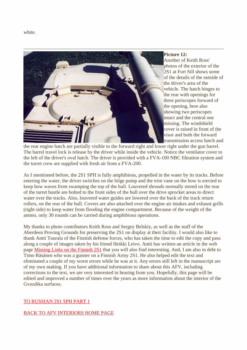
three periscopes forward of the opening, here also showing two periscopes intact and the central one
windshield f the
The barrel travel lock is release by the driver while inside the vehicle. Notice the ventilator cover to the left of the driver's oval hatch. The driver is provided with a FVA-1 the turret crew are supplied with fresh air from a FVA-200. As I mentioned before, the 2S1 SPH is fully amphibious, propelled in the water by its tracks. Before entering the water, the driver switches on the bilge pump and the trim vane on the bow is erected to keep bow waves from swamping the top of the hull. Louvered shrouds r of the turret bustle are bolted to the front sides of the hull over the drivwater over the tracks. Also, louvered water guides are lowered over throllers, on the rear of the hull. Covers are also attached over the engine(right side) to keep water from flooding the engine compartment. Becaammo, only 30 rounds can be carried during amphibious operations.
s d Heikki Leivo. Antti has written an article in the web
Picture 12: Another of Keith Rophotos of the exterior o2S1 at Fort Sill shows somof the details of the outsidthe driver's area of the vehicle. The hatch hinges to the rear with openings for
missing. The cover is raised in front ovisor and both the forward transmission access hatch andr right under the gun barrel.
00 NBC filtration system and
normally stored on the reae sprocket areas to direct e back of the track return air intakes and exhaust grills use of the weight of the
My thanks to photo contributors Keith Ross and Sergey Belskiy, as well as the staff of the Aberdeen Proving Grounds for preserving the 2S1 on display at their facility. I would also like to thank Antti Tuurala of the Finnish defense forces, who has taken the time to edit the copy and pasalong a couple of images taken by his frienpage
the rear engine hatch are partially visible to the forward right and lowe
Missing Links on the Finnish 2S1 that you will also find interesting. And, I am also in debt to Timo Räsänen who was a gunner on a Finnish Army 2S1. He also helped edit the text and eliminated a couple of my worst errors while he was at it. Any errors still left in the manuscript are of my own making. If you have additional information to share about this AFV, including corrections to the text, we are very interested in hearing from you. Hopefully, this page will be edited and improved a number of times over the years as more information about the interior of the Gvozdika surfaces.
TO RUSSIAN 2S1 SPH PART 1 BACK TO AFV INTERIORS HOME PAGE

(c) 2001, AFV INTERIORS Web Magazine