Embed Size (px)
Citation preview

MCINTOSH ENGINEERING North Bay, Ontario Tempe, Arizona
Hard Rock Miners Handbook
Rules of Thumb
Tempe, Arizona North Bay, Ontario Sudbury, Ontario Yellowknife, NWT Vancouver, British Columbia
McIntosh Engineering Contact Information
Canadian Operations Main Office
John Boaro, Operations Manager 147 McIntyre Street West, Suite 200
North Bay, Ontario P1B 2Y5 Canada E-mail:
[email protected] Tel: (705) 494-8255, x-1264
USA Operations Main Office
Sandy Watson, Operations Manager 1438 W. Broadway Road, Suite 101
Tempe, Arizona 85282 USA
E-mail: [email protected]
Tel: (480) 831-0310, x-208
Scott McIntosh, CEO McIntosh Engineering
1438 W. Broadway Road, Suite 101 Tempe, Arizona 85282
USA
E-mail: [email protected]
Tel: (480) 831-0310, x-211 Fax: (480) 730-7083
Canadian Branch Offices
www.McIntoshEngineering.com
Yellowknife, NWT Phil Hansman, Operations Manager
Diamond Field Industrial Plaza #200 – 349 Old Airport Road Yellowknife, NT X1A 3X6
Email: [email protected]
Tel: (867) 920-2363
Sudbury, Ontario Pat Smyth, Operations Manager
1460 Fairburn Street Sudbury, Ontario P3A 1N7
Email: [email protected]
Tel: (705) 566-6891, x 222
Vancouver, British Columbia Mike Gray, Sr. VP Growth and Innovation
Suite 200 Good Earth Building 595 Howe Street
Vancouver, BC V6C 2T5 Email: [email protected]
Tel: (604) 683-3855
MINING CONSULTING McIntosh Engineering Ltd. McIntosh Engineering Inc. ENGINEERING & DESIGN 147 McIntyre Street West 1438 W. Broadway Road CONSTRUCTION MANAGEMENT Suite 200 Suite 101 APPLIED TECHNOLOGIES North Bay, Ontario P1B 9N8 Tempe, Arizona 85282 ENGINEERED PRODUCTS Canada USA Tel: (705) 494-8255 Tel: (480) 831-0310 Fax: (705) 474-2652 Fax: (480) 831-0317
McIntosh Engineering Hard Rock Miner’s Handbook
Rules of Thumb The attached booklet, Hard Rock Miner’s Hand Book - Rules of Thumb is an extraction of 680 mining Rules of Thumb contained in the Hard Rock Miners Handbook – Edition 3 published by McIntosh Engineering in June 2003. The Hard Rock Miner’s Handbook is available in CD format (July 2003) and hardcopy (September 2003) and includes 29 updated chapters, one new chapter on Project Management, and over 100 new mining Rules of Thumb (680 in total) since the original June 2000 publication. In addition to Rules of Thumb, each chapter of the Handbook contains text discussion, example problems, and additional “tricks of the trade”. If you would like to download the Handbook, please visit our web site (www.McIntoshEngineering.com). McIntosh Engineering McIntosh Engineering is an engineering and project management services organization focused on creating value for our mining clients and others we serve. If you are interested in learning more about McIntosh Engineering please feel free to contact me personally at the e-mail address below or contact any of our offices. I sincerely hope that the Hard Rock Miners Handbook and attached Rules of Thumb bring you great mining value and I look forward to hearing from you with comments and new rules of thumb. Sincerely, McIntosh Engineering Scott McIntosh [email protected]
Hard Rock Miners Handbook
Rules of Thumb
Introduction
This document contains a list of over 680 Rules of Thumb gathered over 30 years of hard rock mining service provided by Jack de la Vergne, McIntosh Engineering and predecessor firms. We have endeavored to provide Rules of Thumb for every applicable area in the industry. The list is an excerpt from the Hard Rock Miner’s Handbook, Edition 3, published June 2003. To facilitate usefulness, the attached compilation is sorted by topic.
Our objective in producing the Rules is to present a gift of value to the industry in return for providing our main source of revenue for many years, sustaining our business, and providing gainful employment for members of our team.
History
Rules of Thumb constituted the sole body of mining knowledge until the disciplines of science and engineering first evolved.
Agricola first introduced methodology to the mining industry in the sixteenth century, exemplified in his book entitled De Re Metalica. In this huge volume, he set out principles, standards, and provided Rules of Thumb for mining, concentration, and smelting. The following excerpt provides an example of how mining depended on Rules of Thumb at that time:
"Now when a miner finds a vena profunda, he begins sinking a shaft two fathoms in breadth, two-thirds of a fathom wide, and thirteen fathoms deep."
More than three hundred years later, in 1891, the Royal Commission on Mineral Resources in Ontario, Canada stated that we had been "mining by rule of thumb for long enough." They probably never imagined that over one hundred years later we not only continue to employ these Rules, but they retain a fundamental role in the mining sector.
Definition
What is a Rule of Thumb? A definition is necessary that offers good application in the Hard Rock Mining Industry. Webster’s defines a "Rule of Thumb" as follows:
1. "A general or approximate principal, procedure or rule based on experience or practice, as opposed to a specific, scientific calculation or estimate;"
2. "A rough practical method of procedure."
As we compiled the attached list of Hard Rock Mining Rules of Thumb, we struggled with the subjectivity surrounding many of the Rules. Is a statement a "Rule of Thumb," or is it simply an arguable opinion? We ultimately decided, somewhat subjectively, that a Rule of Thumb could be whatever we wanted it to be and so have provided our own definition of Hard Rock Mining Rules of Thumb.
Rules of Thumb – Mining Industry Definition
For the mining industry, a Rule of Thumb is an empirical standard. It can be further defined as a pragmatic guideline or "norm" related more to the art than the science of mining. A Rule’s main roles are to provide the perspective required to ensure practical concepts and designs, and to facilitate finding pragmatic solutions for operating problems.
Mining Industry Rules of Thumb – Distinguishing Features
Based on the above definition, and to separate Rules of Thumb from other interesting facts and opinions, we determined that Rules of Thumb generally contain certain distinguishing features. We then developed those features into a set of test questions that can be used as a sieve to qualify a Rule of Thumb.
• Does the Rule contain specific value quantities, such as time, cost, weight, temperature, distance, speed, etc.?
• Can the Rule be used in a practical application? • Is the Rule based on identifiable, repeatable experience? • Is the Rule procedural in nature and relatively independent of other variables or
conditions? • Is the Rule put forward and defended by the experience of a qualified practitioner in the
mining industry? • Can the Rule be checked by other practitioners through review of historical examples
supporting the principle under consideration?
Current Use
In today’s mining industry, problems with design, build, and operations arise every day. Most must be solved promptly. Usually, an approximate answer to a particular question is all that is required in determining an acceptable solution.
Often the participants may not even realize they have employed Rules of Thumb to develop a design concept or trouble shoot a problem. This is one reason that we do not attribute as much value to Rules of Thumb as we should.
The conceptual design of a new mine is an example of an iterative process. Using trial and error assumptions will eventually provide results, but this procedure is slow and cumbersome. A more efficient and effective method is to break the circle by employing Rules of Thumb for key assumptions. Thus, Rules of Thumb are employed to great advantage in preparing mine
feasibility studies and due diligence reports, and in other areas such as setting range limits for controls in PLC programs.
When the time arrives for final design and actual construction, Rules of Thumb are no substitute for sound engineering practices. For example, one Rule of Thumb states, "A shaft should not be located less than 200 feet (60 m) from the crest of an open pit." At least three case histories exist where this Rule was applied to a major shaft installation only to find later that the shaft was too close to the pit. In two cases, circular concrete lined shafts were damaged by ground movement and eventually abandoned for hoisting service but retained for ventilation airways. In the third case, the overburden moved damaging the structures around the shaft collar. The surface plant was saved from eventual collapse by very expensive remedial measures.
As noted in the example above, critical pitfalls must be avoided when using Rules of Thumb. Although most of Rules of Thumb used in mining are sound, some are controversial, ambivalent, or even contradictory. A significant effort has been made to delete unsound Rules from the attached list, but we cannot guarantee the absolute accuracy of any Rule presented.
Future Application
An indisputable future role of the Rules is to develop knowledge-based or "expert" computer models. An example is the simulation of a design process that mimics the decisions of a seasoned engineer or designer with the aim of reliable and consistent performance at lightning speed by a non-specialist. The complex decisions made by designers must be broken down into a set of Rules. The format will be used in conjunction with a database to devise algorithms with which the computer can work. The necessary compilation of the Rules of Thumb and the programming effort will provide the beneficial side effect of forcing consideration of the validity and range of accuracy for each Rule of Thumb employed.
Disclaimer
As stated above, the primary usage of Rules of Thumb should be in the development of conceptual designs and feasibility studies or, when a quick decision is required in the solution of an operating problem. Although an approximated answer, derived from a Rule of Thumb may solve an immediate problem, Rules of Thumb are not a substitute for the application of sound engineering and design methodologies. Although we firmly believe that the presented Rules of Thumb provide great continuing value to our industry, McIntosh Engineering does not guarantee their validity, nor do we (or the referenced individual sources) accept responsibility for application of the Rules of Thumb by others. Where possible, direct quotes have been provided from individual references. However, it is possible that referenced sources may not have directly stated the Rule of Thumb for which they are assigned credit. Although we have endeavored to accurately quote all individual references contained in the Rules of Thumb compilation, we apologize in advance for any misquotes that may be attributed to individual sources. We will provide updates to the Rules of Thumb compilation, as we become aware of corrections that may be necessary.

Questions or comments about the Hard Rock Miners Handbook or the Rule of Thumb, please contact us. Scott McIntosh McIntosh Engineering [email protected] USA Main Office McIntosh Engineering Inc. 1438 W. Broadway Road Suite 101 Tempe, Arizona 85282 USA Tel: (480) 831-0310 Fax: (480) 831-0317
Canada Main Office McIntosh Engineering Limited 147 McIntyre Street West Suite 200 North Bay, Ontario P1B 2Y5 Canada Tel: (705) 494-8255 Fax: (705) 474-2652
T A B L E O F C O N T E N T S
iiii
McIntosh EngineeringMcIntosh EngineeringMcIntosh EngineeringMcIntosh Engineering
Hard Rock Miner’s Handbook Rules of Thumb
Tricks of the Trade Case Histories
Example Problems
Long before science and engineering evolved, Rules of Thumb constituted the sole body of mining knowledge. In 1891, the Royal Commission on mineral resources in Ontario, Canada stated that we had been “mining by rules of thumb for long enough.” The Royal Commission probably never imagined that over 100 years later we not only continue to employ these tools, but we lend more value to them then ever before.
Exploration Geology and Ore Reserves
Rock Mechanics
Mining Methods
Mine Layout
Environmental Engineering
Feasibility Studies
Mineral Economics
Cost Estimating
Shaft Design
Shaft Sinking
Lateral Development and Ramps
Collars and Portals
Drum Hoists
Koepe / Friction Hoists
Wire Ropes, Sheaves, and Conveyances
Headframes and Bins
Conveyors and Feeders
Ventilation and Air Conditioning
Compressed Air
Mine Dewatering
Backfill
Explosives and Drilling
Electrical
Passes, Bins, and Chutes
Crushers and Rockbreakers
Mineral Processing
Infrastructure and Transportation
Mine Maintenance
Project Management
Hard Rock Miner's Handbook Rules of Thumb Edition 3 - 2003
Number Topic Rule of Thumb
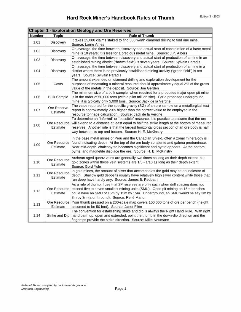
1.01 DiscoveryIt takes 25,000 claims staked to find 500 worth diamond drilling to find one mine. Source: Lorne Ames
1.02 DiscoveryOn average, the time between discovery and actual start of construction of a base metal mine is 10 years; it is less for a precious metal mine. Source: J.P. Albers
1.03 DiscoveryOn average, the time between discovery and actual start of production of a mine in an established mining district (“brown field”) is seven years. Source: Sylvain Paradis
1.04 DiscoveryOn average, the time between discovery and actual start of production of a mine in a district where there is no previously established mining activity (“green field”) is ten years. Source: Sylvain Paradis
1.05 CostsThe amount expended on diamond drilling and exploration development for the purposes of measuring a mineral resource should approximately equal 2% of the gross value of the metals in the deposit. Source: Joe Gerden
1.06 Bulk SampleThe minimum size of a bulk sample, when required for a proposed major open pit mine is in the order of 50,000 tons (with a pilot mill on site). For a proposed underground mine, it is typically only 5,000 tons. Source: Jack de la Vergne
1.07Ore Reserve
Estimate
The value reported for the specific gravity (SG) of an ore sample on a metallurgical test report is approximately 20% higher than the correct value to be employed in the resource tonnage calculation. Source: Jack de la Vergne
1.08Ore Resource
Estimate
To determine an “inferred” or “possible” resource, it is practice to assume that the ore will extend to a distance at least equal to half the strike length at the bottom of measured reserves. Another rule is that the largest horizontal cross section of an ore body is half way between its top and bottom. Source: H. E. McKinstry
1.09Ore Resource
Estimate
In the base metal mines of Peru and the Canadian Shield, often a zonal mineralogy is found indicating depth. At the top of the ore body sphalerite and galena predominate. Near mid-depth, chalcopyrite becomes significant and pyrite appears. At the bottom, pyrite, and magnetite displace the ore. Source: H. E. McKinstry
1.10Ore Resource
Estimate
Archean aged quartz veins are generally two times as long as their depth extent, but gold zones within these vein systems are 1/5 - 1/10 as long as their depth extent. Source: Gord Yule
1.11Ore Resource
Estimate
In gold mines, the amount of silver that accompanies the gold may be an indicator of depth. Shallow gold deposits usually have relatively high silver content while those that run deep have hardly any. Source: James B. Redpath
1.12Ore Resource
Estimate
As a rule of thumb, I use that 2P reserves are only such when drill spacing does not exceed five to seven smallest mining units (SMU). Open pit mining on 15m benches could have an SMU of 15m by 15m by 15m. Underground, an SMU would be say 3m by 3m by 3m (a drift round). Source: René Marion
1.13Ore Resource
EstimateYour thumb pressed on a 200-scale map covers 100,000 tons of ore per bench (height assumed to be 50 feet). Source: Janet Flinn
1.14 Strike and DipThe convention for establishing strike and dip is always the Right Hand Rule. With right hand palm up, open and extended, point the thumb in the down-dip direction and the fingertips provide the strike direction. Source: Mike Neumann
Chapter 1 - Exploration Geology and Ore Reserves
Rules of Thumb compiled by Jack de la Vergne andMcIntosh Engineering Page 1
Hard Rock Miner's Handbook Rules of Thumb Edition 3 - 2003
Number Topic Rule of Thumb
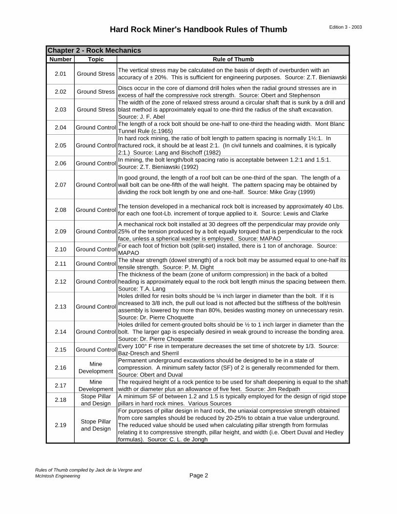
2.01 Ground StressThe vertical stress may be calculated on the basis of depth of overburden with an accuracy of ± 20%. This is sufficient for engineering purposes. Source: Z.T. Bieniawski
2.02 Ground StressDiscs occur in the core of diamond drill holes when the radial ground stresses are in excess of half the compressive rock strength. Source: Obert and Stephenson
2.03 Ground StressThe width of the zone of relaxed stress around a circular shaft that is sunk by a drill and blast method is approximately equal to one-third the radius of the shaft excavation. Source: J. F. Abel
2.04 Ground ControlThe length of a rock bolt should be one-half to one-third the heading width. Mont Blanc Tunnel Rule (c.1965)
2.05 Ground ControlIn hard rock mining, the ratio of bolt length to pattern spacing is normally 1½:1. In fractured rock, it should be at least 2:1. (In civil tunnels and coalmines, it is typically 2:1.) Source: Lang and Bischoff (1982)
2.06 Ground ControlIn mining, the bolt length/bolt spacing ratio is acceptable between 1.2:1 and 1.5:1. Source: Z.T. Bieniawski (1992)
2.07 Ground ControlIn good ground, the length of a roof bolt can be one-third of the span. The length of a wall bolt can be one-fifth of the wall height. The pattern spacing may be obtained by dividing the rock bolt length by one and one-half. Source: Mike Gray (1999)
2.08 Ground ControlThe tension developed in a mechanical rock bolt is increased by approximately 40 Lbs. for each one foot-Lb. increment of torque applied to it. Source: Lewis and Clarke
2.09 Ground ControlA mechanical rock bolt installed at 30 degrees off the perpendicular may provide only 25% of the tension produced by a bolt equally torqued that is perpendicular to the rock face, unless a spherical washer is employed. Source: MAPAO
2.10 Ground ControlFor each foot of friction bolt (split-set) installed, there is 1 ton of anchorage. Source: MAPAO
2.11 Ground ControlThe shear strength (dowel strength) of a rock bolt may be assumed equal to one-half its tensile strength. Source: P. M. Dight
2.12 Ground ControlThe thickness of the beam (zone of uniform compression) in the back of a bolted heading is approximately equal to the rock bolt length minus the spacing between them. Source: T.A. Lang
2.13 Ground Control
Holes drilled for resin bolts should be ¼ inch larger in diameter than the bolt. If it is increased to 3/8 inch, the pull out load is not affected but the stiffness of the bolt/resin assembly is lowered by more than 80%, besides wasting money on unnecessary resin. Source: Dr. Pierre Choquette
2.14 Ground ControlHoles drilled for cement-grouted bolts should be ½ to 1 inch larger in diameter than the bolt. The larger gap is especially desired in weak ground to increase the bonding area. Source: Dr. Pierre Choquette
2.15 Ground ControlEvery 100° F rise in temperature decreases the set time of shotcrete by 1/3. Source: Baz-Dresch and Sherril
2.16Mine
Development
Permanent underground excavations should be designed to be in a state of compression. A minimum safety factor (SF) of 2 is generally recommended for them. Source: Obert and Duval
2.17Mine
DevelopmentThe required height of a rock pentice to be used for shaft deepening is equal to the shaft width or diameter plus an allowance of five feet. Source: Jim Redpath
2.18Stope Pillar and Design
A minimum SF of between 1.2 and 1.5 is typically employed for the design of rigid stope pillars in hard rock mines. Various Sources
2.19Stope Pillar and Design
For purposes of pillar design in hard rock, the uniaxial compressive strength obtained from core samples should be reduced by 20-25% to obtain a true value underground. The reduced value should be used when calculating pillar strength from formulas relating it to compressive strength, pillar height, and width (i.e. Obert Duval and Hedley formulas). Source: C. L. de Jongh
Chapter 2 - Rock Mechanics
Rules of Thumb compiled by Jack de la Vergne andMcIntosh Engineering Page 2
Hard Rock Miner's Handbook Rules of Thumb Edition 3 - 2003
Number Topic Rule of Thumb
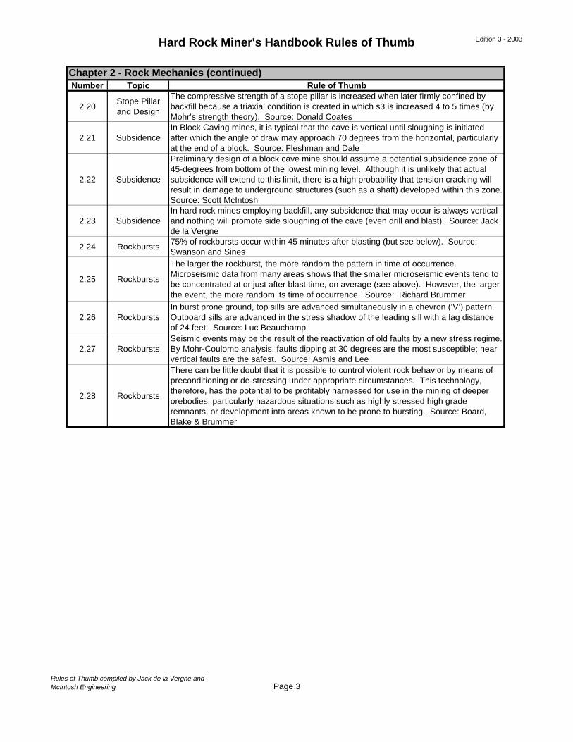
2.20Stope Pillar and Design
The compressive strength of a stope pillar is increased when later firmly confined by backfill because a triaxial condition is created in which s3 is increased 4 to 5 times (by Mohr’s strength theory). Source: Donald Coates
2.21 SubsidenceIn Block Caving mines, it is typical that the cave is vertical until sloughing is initiated after which the angle of draw may approach 70 degrees from the horizontal, particularly at the end of a block. Source: Fleshman and Dale
2.22 Subsidence
Preliminary design of a block cave mine should assume a potential subsidence zone of 45-degrees from bottom of the lowest mining level. Although it is unlikely that actual subsidence will extend to this limit, there is a high probability that tension cracking will result in damage to underground structures (such as a shaft) developed within this zone. Source: Scott McIntosh
2.23 SubsidenceIn hard rock mines employing backfill, any subsidence that may occur is always vertical and nothing will promote side sloughing of the cave (even drill and blast). Source: Jack de la Vergne
2.24 Rockbursts75% of rockbursts occur within 45 minutes after blasting (but see below). Source: Swanson and Sines
2.25 Rockbursts
The larger the rockburst, the more random the pattern in time of occurrence. Microseismic data from many areas shows that the smaller microseismic events tend to be concentrated at or just after blast time, on average (see above). However, the larger the event, the more random its time of occurrence. Source: Richard Brummer
2.26 RockburstsIn burst prone ground, top sills are advanced simultaneously in a chevron (‘V’) pattern. Outboard sills are advanced in the stress shadow of the leading sill with a lag distance of 24 feet. Source: Luc Beauchamp
2.27 RockburstsSeismic events may be the result of the reactivation of old faults by a new stress regime. By Mohr-Coulomb analysis, faults dipping at 30 degrees are the most susceptible; near vertical faults are the safest. Source: Asmis and Lee
2.28 Rockbursts
There can be little doubt that it is possible to control violent rock behavior by means of preconditioning or de-stressing under appropriate circumstances. This technology, therefore, has the potential to be profitably harnessed for use in the mining of deeper orebodies, particularly hazardous situations such as highly stressed high grade remnants, or development into areas known to be prone to bursting. Source: Board, Blake & Brummer
Chapter 2 - Rock Mechanics (continued)
Rules of Thumb compiled by Jack de la Vergne andMcIntosh Engineering Page 3
Hard Rock Miner's Handbook Rules of Thumb Edition 3 - 2003
Number Topic Rule of Thumb
3.01Method
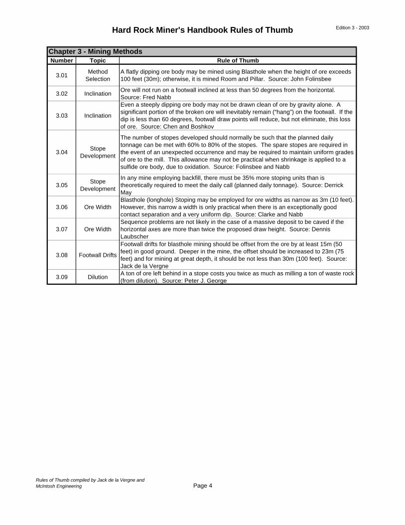
SelectionA flatly dipping ore body may be mined using Blasthole when the height of ore exceeds 100 feet (30m); otherwise, it is mined Room and Pillar. Source: John Folinsbee
3.02 InclinationOre will not run on a footwall inclined at less than 50 degrees from the horizontal. Source: Fred Nabb
3.03 Inclination
Even a steeply dipping ore body may not be drawn clean of ore by gravity alone. A significant portion of the broken ore will inevitably remain (“hang”) on the footwall. If the dip is less than 60 degrees, footwall draw points will reduce, but not eliminate, this loss of ore. Source: Chen and Boshkov
3.04Stope
Development
The number of stopes developed should normally be such that the planned daily tonnage can be met with 60% to 80% of the stopes. The spare stopes are required in the event of an unexpected occurrence and may be required to maintain uniform grades of ore to the mill. This allowance may not be practical when shrinkage is applied to a sulfide ore body, due to oxidation. Source: Folinsbee and Nabb
3.05Stope
Development
In any mine employing backfill, there must be 35% more stoping units than is theoretically required to meet the daily call (planned daily tonnage). Source: Derrick May
3.06 Ore WidthBlasthole (longhole) Stoping may be employed for ore widths as narrow as 3m (10 feet). However, this narrow a width is only practical when there is an exceptionally good contact separation and a very uniform dip. Source: Clarke and Nabb
3.07 Ore WidthSequence problems are not likely in the case of a massive deposit to be caved if the horizontal axes are more than twice the proposed draw height. Source: Dennis Laubscher
3.08 Footwall Drifts
Footwall drifts for blasthole mining should be offset from the ore by at least 15m (50 feet) in good ground. Deeper in the mine, the offset should be increased to 23m (75 feet) and for mining at great depth, it should be not less than 30m (100 feet). Source: Jack de la Vergne
3.09 DilutionA ton of ore left behind in a stope costs you twice as much as milling a ton of waste rock (from dilution). Source: Peter J. George
Chapter 3 - Mining Methods
Rules of Thumb compiled by Jack de la Vergne andMcIntosh Engineering Page 4
Hard Rock Miner's Handbook Rules of Thumb Edition 3 - 2003
Number Topic Rule of Thumb
4.01 Pit Layout
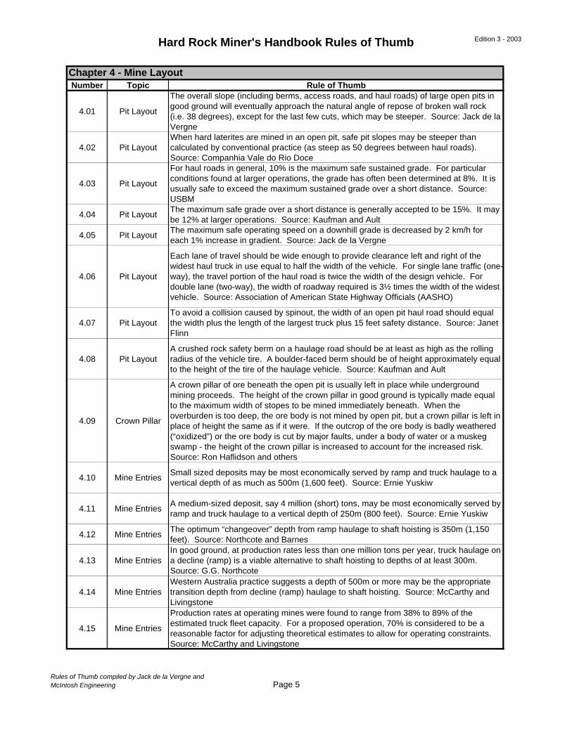
The overall slope (including berms, access roads, and haul roads) of large open pits in good ground will eventually approach the natural angle of repose of broken wall rock (i.e. 38 degrees), except for the last few cuts, which may be steeper. Source: Jack de la Vergne
4.02 Pit LayoutWhen hard laterites are mined in an open pit, safe pit slopes may be steeper than calculated by conventional practice (as steep as 50 degrees between haul roads). Source: Companhia Vale do Rio Doce
4.03 Pit Layout
For haul roads in general, 10% is the maximum safe sustained grade. For particular conditions found at larger operations, the grade has often been determined at 8%. It is usually safe to exceed the maximum sustained grade over a short distance. Source: USBM
4.04 Pit LayoutThe maximum safe grade over a short distance is generally accepted to be 15%. It may be 12% at larger operations. Source: Kaufman and Ault
4.05 Pit LayoutThe maximum safe operating speed on a downhill grade is decreased by 2 km/h for each 1% increase in gradient. Source: Jack de la Vergne
4.06 Pit Layout
Each lane of travel should be wide enough to provide clearance left and right of the widest haul truck in use equal to half the width of the vehicle. For single lane traffic (one-way), the travel portion of the haul road is twice the width of the design vehicle. For double lane (two-way), the width of roadway required is 3½ times the width of the widest vehicle. Source: Association of American State Highway Officials (AASHO)
4.07 Pit LayoutTo avoid a collision caused by spinout, the width of an open pit haul road should equal the width plus the length of the largest truck plus 15 feet safety distance. Source: Janet Flinn
4.08 Pit LayoutA crushed rock safety berm on a haulage road should be at least as high as the rolling radius of the vehicle tire. A boulder-faced berm should be of height approximately equal to the height of the tire of the haulage vehicle. Source: Kaufman and Ault
4.09 Crown Pillar
A crown pillar of ore beneath the open pit is usually left in place while underground mining proceeds. The height of the crown pillar in good ground is typically made equal to the maximum width of stopes to be mined immediately beneath. When the overburden is too deep, the ore body is not mined by open pit, but a crown pillar is left in place of height the same as if it were. If the outcrop of the ore body is badly weathered (“oxidized”) or the ore body is cut by major faults, under a body of water or a muskeg swamp - the height of the crown pillar is increased to account for the increased risk. Source: Ron Haflidson and others
4.10 Mine EntriesSmall sized deposits may be most economically served by ramp and truck haulage to a vertical depth of as much as 500m (1,600 feet). Source: Ernie Yuskiw
4.11 Mine EntriesA medium-sized deposit, say 4 million (short) tons, may be most economically served by ramp and truck haulage to a vertical depth of 250m (800 feet). Source: Ernie Yuskiw
4.12 Mine EntriesThe optimum “changeover” depth from ramp haulage to shaft hoisting is 350m (1,150 feet). Source: Northcote and Barnes
4.13 Mine EntriesIn good ground, at production rates less than one million tons per year, truck haulage on a decline (ramp) is a viable alternative to shaft hoisting to depths of at least 300m. Source: G.G. Northcote
4.14 Mine EntriesWestern Australia practice suggests a depth of 500m or more may be the appropriate transition depth from decline (ramp) haulage to shaft hoisting. Source: McCarthy and Livingstone
4.15 Mine Entries
Production rates at operating mines were found to range from 38% to 89% of the estimated truck fleet capacity. For a proposed operation, 70% is considered to be a reasonable factor for adjusting theoretical estimates to allow for operating constraints. Source: McCarthy and Livingstone
Chapter 4 - Mine Layout
Rules of Thumb compiled by Jack de la Vergne andMcIntosh Engineering Page 5
Hard Rock Miner's Handbook Rules of Thumb Edition 3 - 2003
Number Topic Rule of Thumb
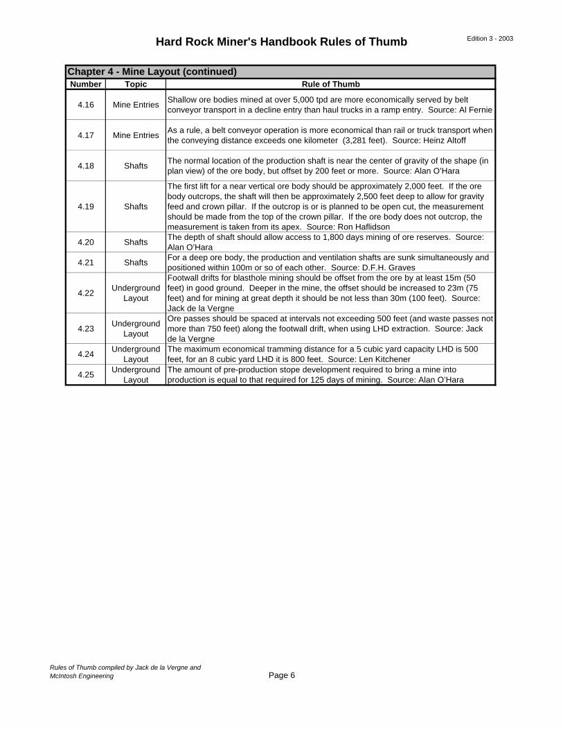
4.16 Mine EntriesShallow ore bodies mined at over 5,000 tpd are more economically served by belt conveyor transport in a decline entry than haul trucks in a ramp entry. Source: Al Fernie
4.17 Mine EntriesAs a rule, a belt conveyor operation is more economical than rail or truck transport when the conveying distance exceeds one kilometer (3,281 feet). Source: Heinz Altoff
4.18 ShaftsThe normal location of the production shaft is near the center of gravity of the shape (in plan view) of the ore body, but offset by 200 feet or more. Source: Alan O’Hara
4.19 Shafts
The first lift for a near vertical ore body should be approximately 2,000 feet. If the ore body outcrops, the shaft will then be approximately 2,500 feet deep to allow for gravity feed and crown pillar. If the outcrop is or is planned to be open cut, the measurement should be made from the top of the crown pillar. If the ore body does not outcrop, the measurement is taken from its apex. Source: Ron Haflidson
4.20 ShaftsThe depth of shaft should allow access to 1,800 days mining of ore reserves. Source: Alan O’Hara
4.21 ShaftsFor a deep ore body, the production and ventilation shafts are sunk simultaneously and positioned within 100m or so of each other. Source: D.F.H. Graves
4.22Underground
Layout
Footwall drifts for blasthole mining should be offset from the ore by at least 15m (50 feet) in good ground. Deeper in the mine, the offset should be increased to 23m (75 feet) and for mining at great depth it should be not less than 30m (100 feet). Source: Jack de la Vergne
4.23Underground
Layout
Ore passes should be spaced at intervals not exceeding 500 feet (and waste passes not more than 750 feet) along the footwall drift, when using LHD extraction. Source: Jack de la Vergne
4.24Underground
LayoutThe maximum economical tramming distance for a 5 cubic yard capacity LHD is 500 feet, for an 8 cubic yard LHD it is 800 feet. Source: Len Kitchener
4.25Underground
LayoutThe amount of pre-production stope development required to bring a mine into production is equal to that required for 125 days of mining. Source: Alan O’Hara
Chapter 4 - Mine Layout (continued)
Rules of Thumb compiled by Jack de la Vergne andMcIntosh Engineering Page 6
Hard Rock Miner's Handbook Rules of Thumb Edition 3 - 2003
Number Topic Rule of Thumb
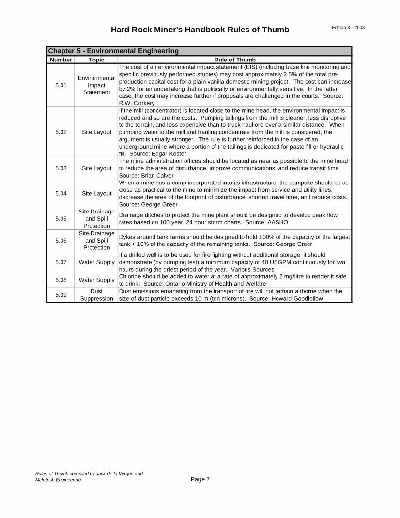
5.01Environmental
Impact Statement
The cost of an environmental impact statement (EIS) (including base line monitoring and specific previously performed studies) may cost approximately 2.5% of the total pre-production capital cost for a plain vanilla domestic mining project. The cost can increase by 2% for an undertaking that is politically or environmentally sensitive. In the latter case, the cost may increase further if proposals are challenged in the courts. Source: R.W. Corkery
5.02 Site Layout
If the mill (concentrator) is located close to the mine head, the environmental impact is reduced and so are the costs. Pumping tailings from the mill is cleaner, less disruptive to the terrain, and less expensive than to truck haul ore over a similar distance. When pumping water to the mill and hauling concentrate from the mill is considered, the argument is usually stronger. The rule is further reinforced in the case of an underground mine where a portion of the tailings is dedicated for paste fill or hydraulic fill. Source: Edgar Köster
5.03 Site LayoutThe mine administration offices should be located as near as possible to the mine head to reduce the area of disturbance, improve communications, and reduce transit time. Source: Brian Calver
5.04 Site Layout
When a mine has a camp incorporated into its infrastructure, the campsite should be as close as practical to the mine to minimize the impact from service and utility lines, decrease the area of the footprint of disturbance, shorten travel time, and reduce costs. Source: George Greer
5.05Site Drainage
and Spill Protection
Drainage ditches to protect the mine plant should be designed to develop peak flow rates based on 100 year, 24 hour storm charts. Source: AASHO
5.06Site Drainage
and Spill Protection
Dykes around tank farms should be designed to hold 100% of the capacity of the largest tank + 10% of the capacity of the remaining tanks. Source: George Greer
5.07 Water SupplyIf a drilled well is to be used for fire fighting without additional storage, it should demonstrate (by pumping test) a minimum capacity of 40 USGPM continuously for two hours during the driest period of the year. Various Sources
5.08 Water SupplyChlorine should be added to water at a rate of approximately 2 mg/litre to render it safe to drink. Source: Ontario Ministry of Health and Welfare
5.09Dust
SuppressionDust emissions emanating from the transport of ore will not remain airborne when the size of dust particle exceeds 10 m (ten microns). Source: Howard Goodfellow
Chapter 5 - Environmental Engineering
Rules of Thumb compiled by Jack de la Vergne andMcIntosh Engineering Page 7

Hard Rock Miner's Handbook Rules of Thumb Edition 3 - 2003
Number Topic Rule of Thumb
6.01 CostThe cost of a detailed feasibility study will be in a range from ½% to 1½% of the total estimated project cost. Source: Frohling and Lewis
6.02 Cost
The cost of a detailed or “bankable” feasibility study is typically in the range of 2% to 5% of the project, if the costs of additional (in-fill) drilling, assaying, metallurgical testing, geotechnical investigations, environmental scrutiny, etc. are added to the direct and indirect costs of the study itself. Source: R. S. Frew
6.03 Time
The definitive feasibility study for a small, simple mining project may be completed in as little as 6-8 weeks. For a medium-sized venture it may take 3-4 months, and a large mining project will take 6-9 months. A world-scale mining project may require more than one year. Source: Bob Rappolt and Mike Gray
6.04 Accuracy
±15% accuracy of capital costs in a detailed feasibility study may be obtained with 15% of the formal engineering completed; ±10% accuracy with 50% completed and ±5% accuracy may be obtained only after formal engineering is complete. Source: Frohling, Lewis and others
6.05Production
RateThe production rate (scale of operations) proposed in a feasibility study should be approximately equal to that given by applying Taylor’s Law. (Refer to Section 6.6)
6.06Production
RateAnnual production should be one-third of the tons per vertical foot times 365 days in a year for a steeply dipping ore body. Source: Ron Cook
6.07Production
Rate
In the case of an orebody that is more or less vertical, the daily tonnage rate may approximate 15% of the tonnes indicated or developed per vertical meter of depth. Source: Northern Miner Press
6.08Production
RateAt many mines, the annual production is equal to 30 vertical meters of ore. Others vary between 25 and 40 meters. Source: Wayne Romer
6.09Production
RateFor a steeply dipping orebody, annual production should not exceed 30 to 40 meters of mine depth. Source: Robin Oram
6.10Production
Rate
For a steeply dipping ore body, the production rate should not exceed 60 meters (vertical) for a small mine. At mines producing over two million tons per year, 30-35 meters per year represents observed practice. Source: McCarthy and Tatman
6.11 DevelopmentPreproduction development should be six months ahead of production. Source: METSInfo
6.12 DevelopmentSix months of production ore should be accessible at all times to ensure stope scheduling and blending. Source: Kirk Rodgers
Chapter 6 - Feasibility Studies
Rules of Thumb compiled by Jack de la Vergne andMcIntosh Engineering Page 8
Hard Rock Miner's Handbook Rules of Thumb Edition 3 - 2003
Number Topic Rule of Thumb
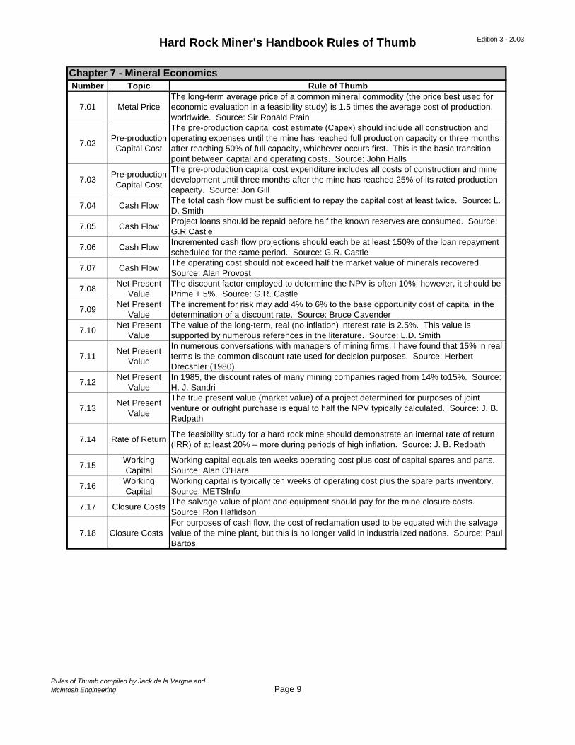
7.01 Metal PriceThe long-term average price of a common mineral commodity (the price best used for economic evaluation in a feasibility study) is 1.5 times the average cost of production, worldwide. Source: Sir Ronald Prain
7.02Pre-production
Capital Cost
The pre-production capital cost estimate (Capex) should include all construction and operating expenses until the mine has reached full production capacity or three months after reaching 50% of full capacity, whichever occurs first. This is the basic transition point between capital and operating costs. Source: John Halls
7.03Pre-production
Capital Cost
The pre-production capital cost expenditure includes all costs of construction and mine development until three months after the mine has reached 25% of its rated production capacity. Source: Jon Gill
7.04 Cash FlowThe total cash flow must be sufficient to repay the capital cost at least twice. Source: L. D. Smith
7.05 Cash FlowProject loans should be repaid before half the known reserves are consumed. Source: G.R Castle
7.06 Cash FlowIncremented cash flow projections should each be at least 150% of the loan repayment scheduled for the same period. Source: G.R. Castle
7.07 Cash FlowThe operating cost should not exceed half the market value of minerals recovered. Source: Alan Provost
7.08Net Present
ValueThe discount factor employed to determine the NPV is often 10%; however, it should be Prime + 5%. Source: G.R. Castle
7.09Net Present
ValueThe increment for risk may add 4% to 6% to the base opportunity cost of capital in the determination of a discount rate. Source: Bruce Cavender
7.10Net Present
ValueThe value of the long-term, real (no inflation) interest rate is 2.5%. This value is supported by numerous references in the literature. Source: L.D. Smith
7.11Net Present
Value
In numerous conversations with managers of mining firms, I have found that 15% in real terms is the common discount rate used for decision purposes. Source: Herbert Drecshler (1980)
7.12Net Present
ValueIn 1985, the discount rates of many mining companies raged from 14% to15%. Source: H. J. Sandri
7.13Net Present
Value
The true present value (market value) of a project determined for purposes of joint venture or outright purchase is equal to half the NPV typically calculated. Source: J. B. Redpath
7.14 Rate of ReturnThe feasibility study for a hard rock mine should demonstrate an internal rate of return (IRR) of at least 20% – more during periods of high inflation. Source: J. B. Redpath
7.15Working Capital
Working capital equals ten weeks operating cost plus cost of capital spares and parts. Source: Alan O’Hara
7.16Working Capital
Working capital is typically ten weeks of operating cost plus the spare parts inventory. Source: METSInfo
7.17 Closure CostsThe salvage value of plant and equipment should pay for the mine closure costs. Source: Ron Haflidson
7.18 Closure CostsFor purposes of cash flow, the cost of reclamation used to be equated with the salvage value of the mine plant, but this is no longer valid in industrialized nations. Source: Paul Bartos
Chapter 7 - Mineral Economics
Rules of Thumb compiled by Jack de la Vergne andMcIntosh Engineering Page 9
Hard Rock Miner's Handbook Rules of Thumb Edition 3 - 2003
Number Topic Rule of Thumb
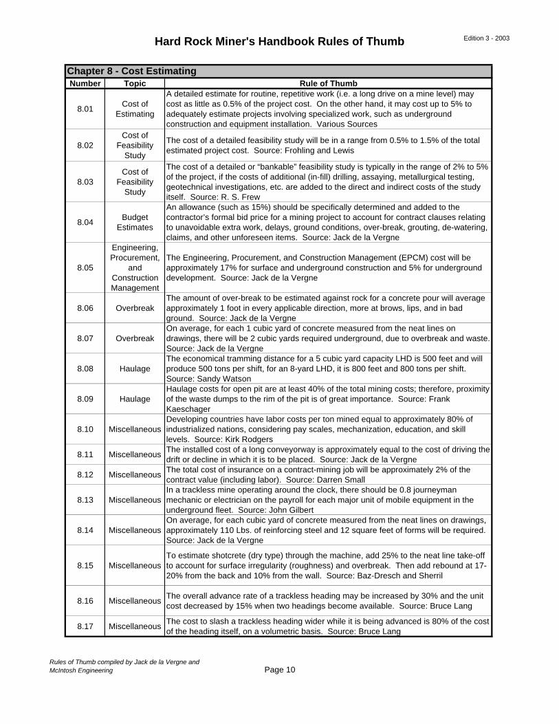
8.01Cost of
Estimating
A detailed estimate for routine, repetitive work (i.e. a long drive on a mine level) may cost as little as 0.5% of the project cost. On the other hand, it may cost up to 5% to adequately estimate projects involving specialized work, such as underground construction and equipment installation. Various Sources
8.02Cost of
Feasibility Study
The cost of a detailed feasibility study will be in a range from 0.5% to 1.5% of the total estimated project cost. Source: Frohling and Lewis
8.03Cost of
Feasibility Study
The cost of a detailed or “bankable” feasibility study is typically in the range of 2% to 5% of the project, if the costs of additional (in-fill) drilling, assaying, metallurgical testing, geotechnical investigations, etc. are added to the direct and indirect costs of the study itself. Source: R. S. Frew
8.04Budget
Estimates
An allowance (such as 15%) should be specifically determined and added to the contractor’s formal bid price for a mining project to account for contract clauses relating to unavoidable extra work, delays, ground conditions, over-break, grouting, de-watering, claims, and other unforeseen items. Source: Jack de la Vergne
8.05
Engineering, Procurement,
and Construction Management
The Engineering, Procurement, and Construction Management (EPCM) cost will be approximately 17% for surface and underground construction and 5% for underground development. Source: Jack de la Vergne
8.06 OverbreakThe amount of over-break to be estimated against rock for a concrete pour will average approximately 1 foot in every applicable direction, more at brows, lips, and in bad ground. Source: Jack de la Vergne
8.07 OverbreakOn average, for each 1 cubic yard of concrete measured from the neat lines on drawings, there will be 2 cubic yards required underground, due to overbreak and waste. Source: Jack de la Vergne
8.08 HaulageThe economical tramming distance for a 5 cubic yard capacity LHD is 500 feet and will produce 500 tons per shift, for an 8-yard LHD, it is 800 feet and 800 tons per shift. Source: Sandy Watson
8.09 HaulageHaulage costs for open pit are at least 40% of the total mining costs; therefore, proximity of the waste dumps to the rim of the pit is of great importance. Source: Frank Kaeschager
8.10 MiscellaneousDeveloping countries have labor costs per ton mined equal to approximately 80% of industrialized nations, considering pay scales, mechanization, education, and skill levels. Source: Kirk Rodgers
8.11 MiscellaneousThe installed cost of a long conveyorway is approximately equal to the cost of driving the drift or decline in which it is to be placed. Source: Jack de la Vergne
8.12 MiscellaneousThe total cost of insurance on a contract-mining job will be approximately 2% of the contract value (including labor). Source: Darren Small
8.13 MiscellaneousIn a trackless mine operating around the clock, there should be 0.8 journeyman mechanic or electrician on the payroll for each major unit of mobile equipment in the underground fleet. Source: John Gilbert
8.14 MiscellaneousOn average, for each cubic yard of concrete measured from the neat lines on drawings, approximately 110 Lbs. of reinforcing steel and 12 square feet of forms will be required. Source: Jack de la Vergne
8.15 MiscellaneousTo estimate shotcrete (dry type) through the machine, add 25% to the neat line take-off to account for surface irregularity (roughness) and overbreak. Then add rebound at 17-20% from the back and 10% from the wall. Source: Baz-Dresch and Sherril
8.16 MiscellaneousThe overall advance rate of a trackless heading may be increased by 30% and the unit cost decreased by 15% when two headings become available. Source: Bruce Lang
8.17 MiscellaneousThe cost to slash a trackless heading wider while it is being advanced is 80% of the cost of the heading itself, on a volumetric basis. Source: Bruce Lang
Chapter 8 - Cost Estimating
Rules of Thumb compiled by Jack de la Vergne andMcIntosh Engineering Page 10
Hard Rock Miner's Handbook Rules of Thumb Edition 3 - 2003
Number Topic Rule of Thumb
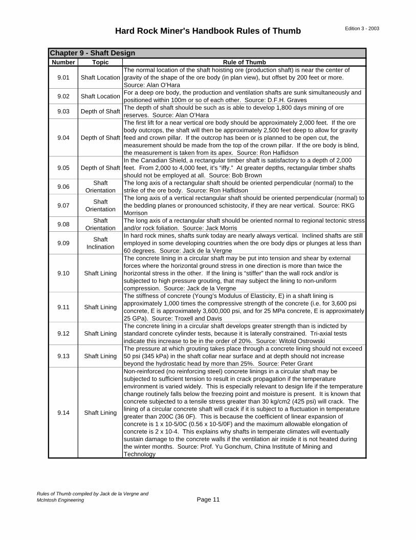
9.01 Shaft LocationThe normal location of the shaft hoisting ore (production shaft) is near the center of gravity of the shape of the ore body (in plan view), but offset by 200 feet or more. Source: Alan O’Hara
9.02 Shaft LocationFor a deep ore body, the production and ventilation shafts are sunk simultaneously and positioned within 100m or so of each other. Source: D.F.H. Graves
9.03 Depth of ShaftThe depth of shaft should be such as is able to develop 1,800 days mining of ore reserves. Source: Alan O’Hara
9.04 Depth of Shaft
The first lift for a near vertical ore body should be approximately 2,000 feet. If the ore body outcrops, the shaft will then be approximately 2,500 feet deep to allow for gravity feed and crown pillar. If the outcrop has been or is planned to be open cut, the measurement should be made from the top of the crown pillar. If the ore body is blind, the measurement is taken from its apex. Source: Ron Haflidson
9.05 Depth of ShaftIn the Canadian Shield, a rectangular timber shaft is satisfactory to a depth of 2,000 feet. From 2,000 to 4,000 feet, it’s “iffy.” At greater depths, rectangular timber shafts should not be employed at all. Source: Bob Brown
9.06Shaft
OrientationThe long axis of a rectangular shaft should be oriented perpendicular (normal) to the strike of the ore body. Source: Ron Haflidson
9.07Shaft
Orientation
The long axis of a vertical rectangular shaft should be oriented perpendicular (normal) to the bedding planes or pronounced schistocity, if they are near vertical. Source: RKG Morrison
9.08Shaft
OrientationThe long axis of a rectangular shaft should be oriented normal to regional tectonic stress and/or rock foliation. Source: Jack Morris
9.09Shaft
Inclination
In hard rock mines, shafts sunk today are nearly always vertical. Inclined shafts are still employed in some developing countries when the ore body dips or plunges at less than 60 degrees. Source: Jack de la Vergne
9.10 Shaft Lining
The concrete lining in a circular shaft may be put into tension and shear by external forces where the horizontal ground stress in one direction is more than twice the horizontal stress in the other. If the lining is “stiffer” than the wall rock and/or is subjected to high pressure grouting, that may subject the lining to non-uniform compression. Source: Jack de la Vergne
9.11 Shaft Lining
The stiffness of concrete (Young’s Modulus of Elasticity, E) in a shaft lining is approximately 1,000 times the compressive strength of the concrete (i.e. for 3,600 psi concrete, E is approximately 3,600,000 psi, and for 25 MPa concrete, E is approximately 25 GPa). Source: Troxell and Davis
9.12 Shaft LiningThe concrete lining in a circular shaft develops greater strength than is indicted by standard concrete cylinder tests, because it is laterally constrained. Tri-axial tests indicate this increase to be in the order of 20%. Source: Witold Ostrowski
9.13 Shaft LiningThe pressure at which grouting takes place through a concrete lining should not exceed 50 psi (345 kPa) in the shaft collar near surface and at depth should not increase beyond the hydrostatic head by more than 25%. Source: Peter Grant
9.14 Shaft Lining
Non-reinforced (no reinforcing steel) concrete linings in a circular shaft may be subjected to sufficient tension to result in crack propagation if the temperature environment is varied widely. This is especially relevant to design life if the temperature change routinely falls below the freezing point and moisture is present. It is known that concrete subjected to a tensile stress greater than 30 kg/cm2 (425 psi) will crack. The lining of a circular concrete shaft will crack if it is subject to a fluctuation in temperature greater than 200C (36 0F). This is because the coefficient of linear expansion of concrete is 1 x 10⁻⁵/0C (0.56 x 10⁻⁵/0F) and the maximum allowable elongation of concrete is 2 x 10⁻⁴. This explains why shafts in temperate climates will eventually sustain damage to the concrete walls if the ventilation air inside it is not heated during the winter months. Source: Prof. Yu Gonchum, China Institute of Mining and Technology
Chapter 9 - Shaft Design
Rules of Thumb compiled by Jack de la Vergne andMcIntosh Engineering Page 11
Hard Rock Miner's Handbook Rules of Thumb Edition 3 - 2003
Number Topic Rule of Thumb
9.15 Shaft Lining
A concrete lining may not be satisfactory in the long run for external pressures exceeding 500 psi (3.5 MPa). Concrete is not absolutely impermeable. When subjected to very high hydrostatic pressure, minute particles of water will eventually traverse the lining and as they approach the interior face (under high differential pressure) they will initiate spalling of small particles of the concrete wall. Eventually, over a period of years, repetitive spalling will destroy the integrity of the lining. Grouting through the lining may temporarily arrest this action, but it will eventually resume. Source: Fred Edwards
9.16 Shaft LiningA University of Texas study found that substituting 25 to 35% fly ash for Portland cement in high strength concrete could cut permeability by more than half, extending the life of the concrete. Source: Engineering-News Record, Jan/98
9.17 Shaft Lining
The mode of buckling failure (collapse) of a steel hydrostatic liner installed in a tunnel displays three nodes while a vertical shaft produces only two (figure 8). This means that a steel shaft or (shaft collar liner) designed to tunnel design standards is likely to collapse (and has). Source: Jack de la Vergne
9.18 Shaft Lining
A safety factor derived from building codes for a dead load (which may be 1.4) has proven inadequate by sorry experience when applied to steel hydrostatic shaft liners. For these, the minimum acceptable factor of safety is 1.7 for a temporary installation and 1.8 for a permanent structure that may be subject to corrosion (rust). Source: Jack de la Vergne
9.19Ventilation Capacity
The maximum practical velocity for ventilation air in a circular concrete production shaft equipped with fixed (rigid) guides is 2,500 fpm (12.7m/s). Source: Richard Masuda
9.20Ventilation Capacity
The economic velocity for ventilation air in a circular concrete production shaft equipped with fixed (rigid) guides is 2,400 fpm (12m/s). If the shaft incorporates a man-way compartment (ladder way), the economic velocity is reduced to about 1,400 fpm (7m/s). Source: A.W.T. Barenbrug
9.21Ventilation Capacity
The maximum velocity that should be contemplated for ventilation air in a circular concrete production shaft equipped with rope guides is 2,000 fpm and the recommended maximum relative velocity between skips and airflow is 6,000 fpm. Source: Malcom McPherson
9.22Ventilation Capacity
The “not-to-exceed” velocity for ventilation air in a bald circular concrete ventilation shaft is 4,000 fpm. Source: Malcom McPherson
9.23Ventilation Capacity
The typical velocity for ventilation air in a bald circular concrete ventilation shaft is in the order of 3,000 fpm to be economical. Source: Jack de la Vergne
9.24 Shaft GuidesThe single most important requirement of a guide string is to have near-perfect joints. Straightness is the second most important, and verticality probably the third. Source: Jim Redpath
9.25 Shaft Guides
The force exerted on a fixed guide from a moving conveyance due to imperfections in the guide string varies (1) in direct proportion to the mass of the conveyance, (2) in direct proportion to the square of the speed of the conveyance, and (3) in inverse proportion to the square of the distance over which the deflection takes place. Source: Lawrence O. Cooper
9.26 Shaft GuidesFor purposes of design, the equivalent static lateral force from a shaft conveyance to the guide string may be taken as 10% of the rope end load (conveyance + payload), provided the hoisting speed does not exceed 2,000 fpm (10m/s). Source: Steve Boyd
9.27 Shaft GuidesFor purposes of design, the calculated deflection of wood guides should not exceed 1/400 and that of steel guides 1/700 of the span between the sets supporting them. Source: German Technical Standards (TAS) 1977
9.28 Shaft GuidesAcceleration values of 8% -10% obtained from a decelerometer test are reasonable rates to expect from a new shaft in good alignment. Source: Keith Jones
Chapter 9 - Shaft Design (continued)
Rules of Thumb compiled by Jack de la Vergne andMcIntosh Engineering Page 12
Hard Rock Miner's Handbook Rules of Thumb Edition 3 - 2003
Number Topic Rule of Thumb
9.29 Shaft GuidesIn an inclined shaft, guides are required for the conveyance cars (to prevent derailing) when the inclination exceeds 70º from the horizontal. Source: Unknown
9.30 Shaft SetsTests initiated at McGill University indicate that a rectangular hollow structural section (HSS) shaft bunton will have 52% of the resistance (to ventilation air) of a standard structural member (I-beam). Source: Bart Thompson
9.31 Shaft StationsAt the mining horizon, the nominal interval for shaft stations is between 150 and 200 feet; however, with full ramp access to the ore body this interval can be higher, as much as 400 feet. Source: Jack de la Vergne
9.32 Shaft StationsAbove the mining horizons, shaft stations are not required for access, but stub stations should be cut at intervals of ±1,000 feet, because this is a good distance for safely supporting steel wire armored or riser teck power cables. Source: Jim Bernas
9.33 Shaft Stations
Above the mining horizons, full shaft stations are not required for access, but intermediate pumping stations are required at intervals not exceeding 2,500 feet (typically 2,000 feet) when shaft dewatering is carried out with centrifugal pumps. They may still be required for shaft sinking and initial development, even though the mine plans for using piston diaphragm pumps for permanent mine dewatering. Source: Andy Pitz
9.34 Shaft StationsThe minimum station depth at a development level to be cut during shaft sinking is at least 50 feet (15m). Source: Tom Goodell
9.35Shaft
Clearances
For a fixed guide system employing steel guides, the minimum clearance between a conveyance and a fixed obstruction (i.e. shaft dividers or shaft walling) is 1½ inches for small, square compartments; otherwise it is 2 inches. Source: Jack de la Vergne
9.36Shaft
Clearances
For a fixed guide system employing wood guides, the minimum clearance between a conveyance and a fixed obstruction (i.e. shaft dividers or shaft walling) is 2½ inches for small, square compartments; otherwise, it is 3 inches. Source: Jack de la Vergne
9.37Shaft
Clearances
For a rope guide system in a production shaft, the minimum clearance between a conveyance and a fixed obstruction is 12 inches and to another conveyance is 20 inches. These clearances may be reduced with the use of rub ropes. Source: George Delorme
9.38Shaft
Clearances
The side-to-side clearance between the skip shoes and guides should be designed ¼ inch and should not exceed 3/8 inch in operation. The total clearance face to face of guides should be ½ to 5/8 inches and not exceed ¾ inch. Source: Largo Albert
9.39 Shaft Spill
For a well-designed skip hoist installation, the amount of shaft spill will equal approximately ½% of the tonnage hoisted. (This rule of thumb is based on interpretation of field measurements carried out at eight separate mines, where the spill typically measured between ¼% and 1% of the tonnage hoisted.) Source: Jack de la Vergne
9.40 Timber ShaftThe classic three-compartment timber shaft employing one hoist for skip and cage service is normally satisfactory for production up to 1,000 tpd, although there are a few case histories with up to twice this rate of production. Source: Jack de la Vergne
9.41 Timber ShaftFor a timber shaft, the minimum dimension of the space between the shaft timber and the wall rock should be 6 inches. Source: Alan Provost
9.42 Timber Shaft For a timber shaft, set spacing should not exceed 8 feet. Source: J.C. McIsaac
9.43 Timber ShaftFor a timber shaft, catch pits are typically installed every six sets (intervals of approximately 50 feet). Source: Jim Redpath
Chapter 9 - Shaft Design (continued)
Rules of Thumb compiled by Jack de la Vergne andMcIntosh Engineering Page 13
Hard Rock Miner's Handbook Rules of Thumb Edition 3 - 2003
Number Topic Rule of Thumb
10.01 ScheduleFrom time of award to the start of sinking a timber shaft will be approximately five months. A circular concrete shaft may take three months longer unless the shaft collar and headframe are completed in advance. Source: Tom Anderson
10.02 ScheduleThe average rate of advance for shaft sinking will be two-thirds of the advance in the best month (the one everyone talks about). Source: Jim Redpath
10.03 HoistThe hoist required for shaft sinking needs approximately 30% more horsepower than for skipping the same payload at the same line speed. Source: Jack de la Vergne
10.04 Hoist
Without slowing the rate of advance, a single drum hoist is satisfactory to sink to a depth of 1,500 feet at five buckets per foot, 2,000 feet at four buckets per foot, and 2,500 feet at 3½ buckets per foot. For deeper shafts, a double-drum hoist is required to keep up with the shaft mucker. Source: Jack de la Vergne
10.05 BucketFor sinking a vertical shaft, the bucket size should be at least big enough to fill six for each foot of shaft to be sunk; five is better. Source: Marshall Hamilton
10.06 BucketFor the bucket to remain stable when detached on the shaft bottom, its height should not exceed its diameter by more than 50%. Source: Jim Redpath
10.07 BucketTall buckets can be used safely if the clam is used to dig a hole in the muck pile for the buckets. Source: Bill Shaver
10.08 BucketA bucket should not be higher than 7½ feet for filling with a standard Cryderman clam (which has an 11-foot stroke). Source: Bert Trenfield
10.09 BucketA bucket should not be higher than 6 feet when mucking with a 630, which has a 6-foot-6-inch discharge height. Source: Alan Provost
10.10 BucketYou can load a tall bucket using a 630 if you slope the muck pile so that the bucket sits at an angle from the vertical position. Source: Fern Larose
10.11 BucketIn a wet shaft, the contractor should be able to bail up to 10 buckets of water per shift without impeding his advance. Source: Paddy Harrison
10.12Water
Pressure
For any shaft, the water pressure reducing valves should be installed every 250 feet. “Toilet tank” reducers are more reliable than valves and may be spread further apart. Source: Peter van Schaayk
10.13Water
Pressure
Water pressure reducing valves may be eliminated for shaft sinking if the water line is slotted and the drill water is fed in batch quantities. Sources: Allan Widlake and Jannie Mostert
10.14Compressed
AirOne thousand cfm of compressed air is needed to blow the bench with a two-inch blowpipe. Source: Bill Shaver
10.15Compressed
AirTwelve hundred cfm of compressed air is needed to operate a standard Cryderman clam properly. Source: Bill Shaver
10.16 Shaft StationsThe minimum station depth at a development level to be cut during shaft sinking is 50 feet. Source: Tom Goodell
10.17 Shaft StationsA shaft station will not be cut faster than 2,000 cubic feet per day with slusher mucking. It may be cut at an average rate of 3,500 cubic feet per day with an LHD mucking unit. Source: Jim Redpath
10.18 Circular ShaftThe minimum (finished) diameter of a circular shaft for bottom mucking with a 630-crawler loader is 18 feet. Source: Tom Goodell
10.19 Circular ShaftWith innovation (use a tugger), a 15-foot diameter shaft can be mucked with a 630 crawler-loader. Source: Darrel Vliegenthart
10.20 Circular ShaftFor a circular concrete shaft, the minimum clearance between the sinking stage and the shaft walls is 10 inches. Source: Henry Lavigne
10.21 Circular ShaftA circular concrete lined shaft sunk in good ground will have an average overbreak of 10 inches or more, irrespective of the minimum concrete thickness. Source: Jim Redpath
Chapter 10 - Shaft Sinking
Rules of Thumb compiled by Jack de la Vergne andMcIntosh Engineering Page 14
Hard Rock Miner's Handbook Rules of Thumb Edition 3 - 2003
Number Topic Rule of Thumb
10.22 Circular Shaft
For a rope guide system in a shaft being sunk to a moderate depth, the minimum clearance between a conveyance (bucket and crosshead) and a fixed obstruction is 12 inches and to another bucket is 24 inches. At the shaft collar, the clearance to a fixed obstruction may be reduced to 6 inches due to slowdown, or less with the use of fairleads or skid plates. In a deep shaft, 18-24 inches is required to clear a fixed obstruction and 30-36 inches is required between buckets, depending on the actual hoisting speed. These clearances assume that the shaft stage hangs free and the guide ropes are fully tensioned when hoisting buckets. Various Sources
10.23 Circular ShaftWhen hoisting at speeds approaching 3,000 fpm (15m/s) on a rope guide system, the bonnet of the crosshead should be grilled instead of being constructed of steel plate to minimize aerodynamic sway. Source: Morris Medd
10.24 Circular ShaftThe maximum rate at which ready-mix concrete will be poured down a 6-inch diameter slick line is 60 cubic yards per hour. Source: Marshall Hamilton
10.25 Circular ShaftTo diminish wear and reduce vibration, the boot (“velocity killer”) at the bottom end of the concrete slick line should be extended in length by 6 inches and the impact plate thickened by one inch for each 1,000 feet of depth. Source: R. N. Lambert
10.26 Timber ShaftFor a timber shaft, the minimum clearance to the wall rock outside wall plates and end plates should be 6 inches; the average will be 14 inches in good ground. Source: Alan Provost
10.27 Timber ShaftFor a timber shaft that encounters squeezing ground, the minimum clearance outside wall plates and end plates should be 12 inches. Source: Dan Hinich
10.28 Timber ShaftFor a timber shaft, the blocking should not be longer than two feet without being pinned with rock bolts to the wall rock. Source: Jim Redpath
Chapter 10 - Shaft Sinking (continued)
Rules of Thumb compiled by Jack de la Vergne andMcIntosh Engineering Page 15
Hard Rock Miner's Handbook Rules of Thumb Edition 3 - 2003
Number Topic Rule of Thumb
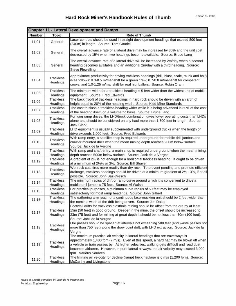
11.01 GeneralLaser controls should be used in straight development headings that exceed 800 feet (240m) in length. Source: Tom Goodell
11.02 GeneralThe overall advance rate of a lateral drive may be increased by 30% and the unit cost decreased by 15% when two headings become available. Source: Bruce Lang
11.03 GeneralThe overall advance rate of a lateral drive will be increased by 2m/day when a second heading becomes available and an additional 2m/day with a third heading. Source: Steve Flewelling
11.04Trackless Headings
Approximate productivity for driving trackless headings (drill, blast, scale, muck and bolt) is as follows: 0.3-0.5 m/manshift for a green crew; 0.7-0.8 m/manshift for competent crews; and 1.0-1.25 m/manshift for real highballers. Source: Robin Oram
11.05Trackless Headings
The minimum width for a trackless heading is 5 feet wider than the widest unit of mobile equipment. Source: Fred Edwards
11.06Trackless Headings
The back (roof) of trackless headings in hard rock should be driven with an arch of height equal to 20% of the heading width. Source: Kidd Mine Standards
11.07Trackless Headings
The cost to slash a trackless heading wider while it is being advanced is 80% of the cost of the heading itself, on a volumetric basis. Source: Bruce Lang
11.08Trackless Headings
For long ramp drives, the LHD/truck combination gives lower operating costs than LHDs alone and should be considered on any haul more than 1,500 feet in length. Source: Jack Clark
11.09Trackless Headings
LHD equipment is usually supplemented with underground trucks when the length of drive exceeds 1,000 feet. Source: Fred Edwards
11.10Trackless Headings
With ramp entry, a satellite shop is required underground for mobile drill jumbos and crawler mounted drills when the mean mining depth reaches 200m below surface. Source: Jack de la Vergne
11.11Trackless Headings
With ramp and shaft entry, a main shop is required underground when the mean mining depth reaches 500m below surface. Source: Jack de la Vergne
11.12Trackless Headings
A gradient of 2% is not enough for a horizontal trackless heading. It ought to be driven at a minimum of 2½% or 3%. Source: Bill Shaver
11.13Trackless Headings
Wet rock cuts tires more readily than dry rock. To prevent ponding and promote efficient drainage, trackless headings should be driven at a minimum gradient of 2½ - 3%, if at all possible. Source: John Baz-Dresch
11.14Trackless Headings
The minimum radius of drift or ramp curve around which it is convenient to drive a mobile drill jumbo is 75 feet. Source: Al Walsh
11.15Trackless Headings
For practical purposes, a minimum curve radius of 50 feet may be employed satisfactorily for most ramp headings. Source: John Gilbert
11.16Trackless Headings
The gathering arm reach of a continuous face-mucking unit should be 2 feet wider than the nominal width of the drift being driven. Source: Jim Dales
11.17Trackless Headings
Footwall drifts for trackless blasthole mining should be offset from the ore by at least 15m (50 feet) in good ground. Deeper in the mine, the offset should be increased to 23m (75 feet) and for mining at great depth it should be not less than 30m (100 feet). Source: Jack de la Vergne
11.18Trackless Headings
Ore passes should be spaced at intervals not exceeding 500 feet (and waste passes not more than 750 feet) along the draw point drift, with LHD extraction. Source: Jack de la Vergne
11.19Trackless Headings
The maximum practical air velocity in lateral headings that are travelways is approximately 1,400 fpm (7 m/s). Even at this speed, a hard hat may be blown off when a vehicle or train passes by. At higher velocities, walking gets difficult and road dust becomes airborne. However, in pure lateral airways, the air velocity may exceed 3,000 fpm. Various Sources
11.20Trackless Headings
The limiting air velocity for decline (ramp) truck haulage is 6 m/s (1,200 fpm). Source: McCarthy and Livingstone
Chapter 11 - Lateral Development and Ramps
Rules of Thumb compiled by Jack de la Vergne andMcIntosh Engineering Page 16
Hard Rock Miner's Handbook Rules of Thumb Edition 3 - 2003
Number Topic Rule of Thumb
11.21Trackless Headings
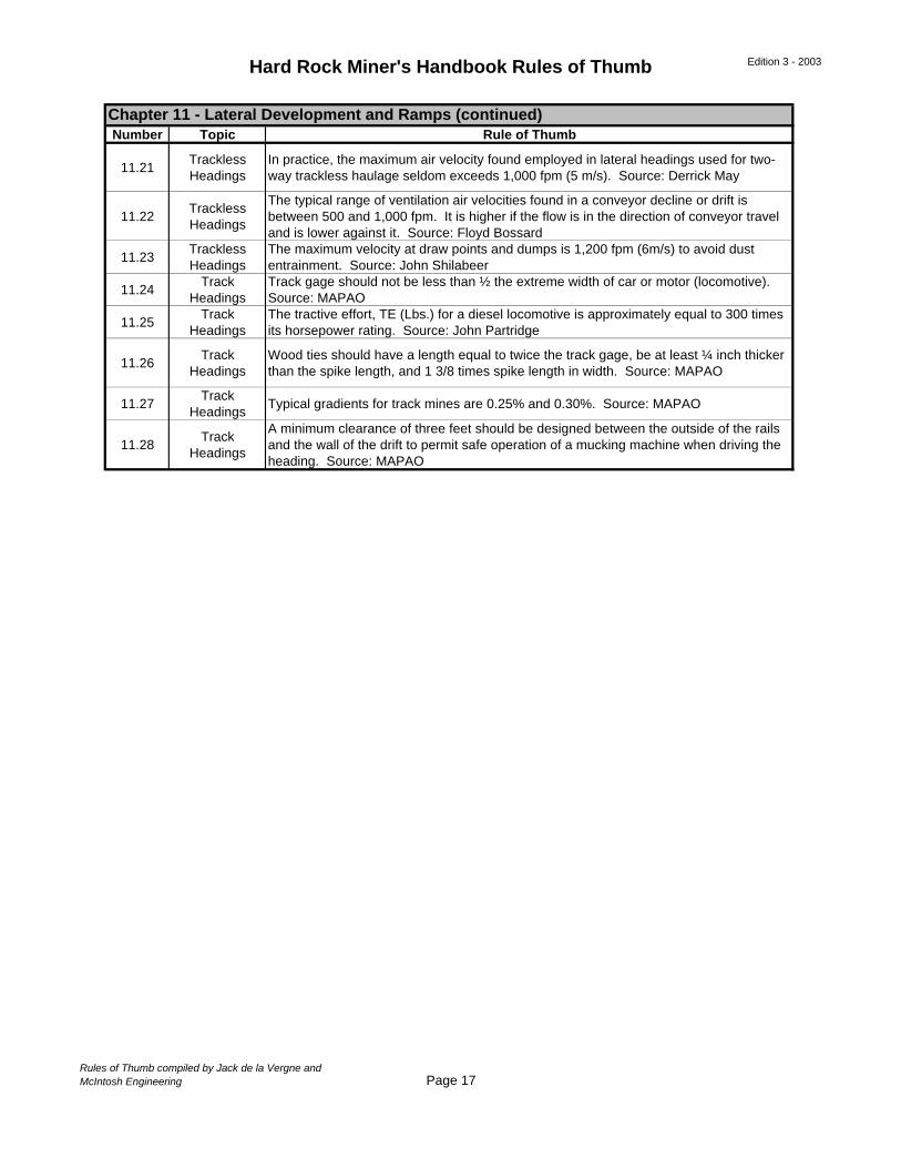
In practice, the maximum air velocity found employed in lateral headings used for two-way trackless haulage seldom exceeds 1,000 fpm (5 m/s). Source: Derrick May
11.22Trackless Headings
The typical range of ventilation air velocities found in a conveyor decline or drift is between 500 and 1,000 fpm. It is higher if the flow is in the direction of conveyor travel and is lower against it. Source: Floyd Bossard
11.23Trackless Headings
The maximum velocity at draw points and dumps is 1,200 fpm (6m/s) to avoid dust entrainment. Source: John Shilabeer
11.24Track
HeadingsTrack gage should not be less than ½ the extreme width of car or motor (locomotive). Source: MAPAO
11.25Track
HeadingsThe tractive effort, TE (Lbs.) for a diesel locomotive is approximately equal to 300 times its horsepower rating. Source: John Partridge
11.26Track
HeadingsWood ties should have a length equal to twice the track gage, be at least ¼ inch thicker than the spike length, and 1 3/8 times spike length in width. Source: MAPAO
11.27Track
HeadingsTypical gradients for track mines are 0.25% and 0.30%. Source: MAPAO
11.28Track
Headings
A minimum clearance of three feet should be designed between the outside of the rails and the wall of the drift to permit safe operation of a mucking machine when driving the heading. Source: MAPAO
Chapter 11 - Lateral Development and Ramps (continued)
Rules of Thumb compiled by Jack de la Vergne andMcIntosh Engineering Page 17
Hard Rock Miner's Handbook Rules of Thumb Edition 3 - 2003
Number Topic Rule of Thumb
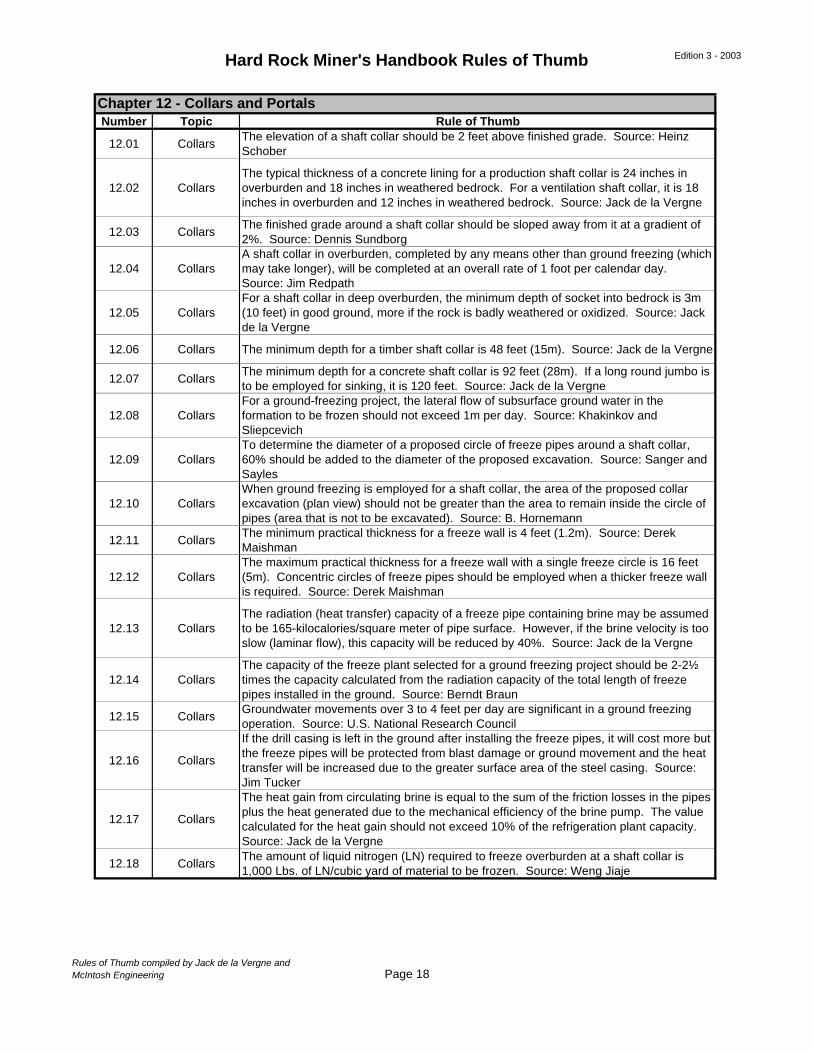
12.01 CollarsThe elevation of a shaft collar should be 2 feet above finished grade. Source: Heinz Schober
12.02 CollarsThe typical thickness of a concrete lining for a production shaft collar is 24 inches in overburden and 18 inches in weathered bedrock. For a ventilation shaft collar, it is 18 inches in overburden and 12 inches in weathered bedrock. Source: Jack de la Vergne
12.03 CollarsThe finished grade around a shaft collar should be sloped away from it at a gradient of 2%. Source: Dennis Sundborg
12.04 CollarsA shaft collar in overburden, completed by any means other than ground freezing (which may take longer), will be completed at an overall rate of 1 foot per calendar day. Source: Jim Redpath
12.05 CollarsFor a shaft collar in deep overburden, the minimum depth of socket into bedrock is 3m (10 feet) in good ground, more if the rock is badly weathered or oxidized. Source: Jack de la Vergne
12.06 Collars The minimum depth for a timber shaft collar is 48 feet (15m). Source: Jack de la Vergne
12.07 CollarsThe minimum depth for a concrete shaft collar is 92 feet (28m). If a long round jumbo is to be employed for sinking, it is 120 feet. Source: Jack de la Vergne
12.08 CollarsFor a ground-freezing project, the lateral flow of subsurface ground water in the formation to be frozen should not exceed 1m per day. Source: Khakinkov and Sliepcevich
12.09 CollarsTo determine the diameter of a proposed circle of freeze pipes around a shaft collar, 60% should be added to the diameter of the proposed excavation. Source: Sanger and Sayles
12.10 CollarsWhen ground freezing is employed for a shaft collar, the area of the proposed collar excavation (plan view) should not be greater than the area to remain inside the circle of pipes (area that is not to be excavated). Source: B. Hornemann
12.11 CollarsThe minimum practical thickness for a freeze wall is 4 feet (1.2m). Source: Derek Maishman
12.12 CollarsThe maximum practical thickness for a freeze wall with a single freeze circle is 16 feet (5m). Concentric circles of freeze pipes should be employed when a thicker freeze wall is required. Source: Derek Maishman
12.13 CollarsThe radiation (heat transfer) capacity of a freeze pipe containing brine may be assumed to be 165-kilocalories/square meter of pipe surface. However, if the brine velocity is too slow (laminar flow), this capacity will be reduced by 40%. Source: Jack de la Vergne
12.14 CollarsThe capacity of the freeze plant selected for a ground freezing project should be 2-2½ times the capacity calculated from the radiation capacity of the total length of freeze pipes installed in the ground. Source: Berndt Braun
12.15 CollarsGroundwater movements over 3 to 4 feet per day are significant in a ground freezing operation. Source: U.S. National Research Council
12.16 Collars
If the drill casing is left in the ground after installing the freeze pipes, it will cost more but the freeze pipes will be protected from blast damage or ground movement and the heat transfer will be increased due to the greater surface area of the steel casing. Source: Jim Tucker
12.17 Collars
The heat gain from circulating brine is equal to the sum of the friction losses in the pipes plus the heat generated due to the mechanical efficiency of the brine pump. The value calculated for the heat gain should not exceed 10% of the refrigeration plant capacity. Source: Jack de la Vergne
12.18 CollarsThe amount of liquid nitrogen (LN) required to freeze overburden at a shaft collar is 1,000 Lbs. of LN/cubic yard of material to be frozen. Source: Weng Jiaje
Chapter 12 - Collars and Portals
Rules of Thumb compiled by Jack de la Vergne andMcIntosh Engineering Page 18

Hard Rock Miner's Handbook Rules of Thumb Edition 3 - 2003
Number Topic Rule of Thumb
12.19 Collars
Due to the heat of hydration, the long-term strength of concrete poured against frozen ground will not be affected if the thickness exceeds 0.45m (18 inches). Below this thickness, designers will sometimes allow a skin of about 70-mm (2¾ inches). Source: Derek Maishman
12.20 Portals
The minimum brow for a portal in good ground (sound rock) is normally equal to the width of the decline or ramp entry. It may be reduced in steeply sloped terrain or leaving “shoulders” (instead of a vertical face) and/or by proper ground support with resin grouted rebar bolts. Various Sources
12.21 PortalsWhen slurry walls, freeze walls, or sheet piling are employed for portal entries in deep, saturated overburden, they should be placed to a depth 50% greater than the depth of the excavation to avoid uplift on the bottom. Source: Jacobs Engineering
12.22 PortalsThe maximum practical depth for sheet piling in cohesive soils approximately 60 feet (18m). In granular soils, it is usually little more than 40 feet (12m). Source: Jack de la Vergne
12.23 PortalsStandard well point systems are based on suction (vacuum) lift and the practical limit for lowering the groundwater is normally about 5m (16 feet). It is typical to provide a second stage of well points to lower it further. Source: Stang Dewatering Systems
12.24 PortalsWell point systems employing jet eductor pumps are capable of lowering the ground water by 12 to 15m (40 to 50 feet) in one lift. Source: Golder Associates
Chapter 12 - Collars and Portals (continued)
Rules of Thumb compiled by Jack de la Vergne andMcIntosh Engineering Page 19
Hard Rock Miner's Handbook Rules of Thumb Edition 3 - 2003
Number Topic Rule of Thumb
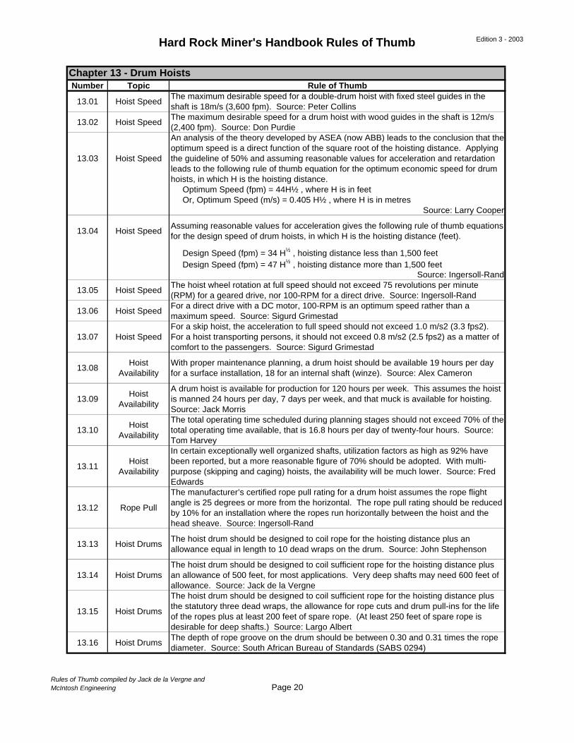
13.01 Hoist SpeedThe maximum desirable speed for a double-drum hoist with fixed steel guides in the shaft is 18m/s (3,600 fpm). Source: Peter Collins
13.02 Hoist SpeedThe maximum desirable speed for a drum hoist with wood guides in the shaft is 12m/s (2,400 fpm). Source: Don Purdie
13.03 Hoist Speed
An analysis of the theory developed by ASEA (now ABB) leads to the conclusion that the optimum speed is a direct function of the square root of the hoisting distance. Applying the guideline of 50% and assuming reasonable values for acceleration and retardation leads to the following rule of thumb equation for the optimum economic speed for drum hoists, in which H is the hoisting distance. Optimum Speed (fpm) = 44H½ , where H is in feet Or, Optimum Speed (m/s) = 0.405 H½ , where H is in metres
Source: Larry Cooper
13.04 Hoist SpeedAssuming reasonable values for acceleration gives the following rule of thumb equations for the design speed of drum hoists, in which H is the hoisting distance (feet).
Design Speed (fpm) = 34 H½ , hoisting distance less than 1,500 feet Design Speed (fpm) = 47 H½ , hoisting distance more than 1,500 feet
Source: Ingersoll-Rand
13.05 Hoist SpeedThe hoist wheel rotation at full speed should not exceed 75 revolutions per minute (RPM) for a geared drive, nor 100-RPM for a direct drive. Source: Ingersoll-Rand
13.06 Hoist SpeedFor a direct drive with a DC motor, 100-RPM is an optimum speed rather than a maximum speed. Source: Sigurd Grimestad
13.07 Hoist SpeedFor a skip hoist, the acceleration to full speed should not exceed 1.0 m/s2 (3.3 fps2). For a hoist transporting persons, it should not exceed 0.8 m/s2 (2.5 fps2) as a matter of comfort to the passengers. Source: Sigurd Grimestad
13.08Hoist
AvailabilityWith proper maintenance planning, a drum hoist should be available 19 hours per day for a surface installation, 18 for an internal shaft (winze). Source: Alex Cameron
13.09Hoist
Availability
A drum hoist is available for production for 120 hours per week. This assumes the hoist is manned 24 hours per day, 7 days per week, and that muck is available for hoisting. Source: Jack Morris
13.10Hoist
Availability
The total operating time scheduled during planning stages should not exceed 70% of the total operating time available, that is 16.8 hours per day of twenty-four hours. Source: Tom Harvey
13.11Hoist
Availability
In certain exceptionally well organized shafts, utilization factors as high as 92% have been reported, but a more reasonable figure of 70% should be adopted. With multi-purpose (skipping and caging) hoists, the availability will be much lower. Source: Fred Edwards
13.12 Rope Pull
The manufacturer’s certified rope pull rating for a drum hoist assumes the rope flight angle is 25 degrees or more from the horizontal. The rope pull rating should be reduced by 10% for an installation where the ropes run horizontally between the hoist and the head sheave. Source: Ingersoll-Rand
13.13 Hoist DrumsThe hoist drum should be designed to coil rope for the hoisting distance plus an allowance equal in length to 10 dead wraps on the drum. Source: John Stephenson
13.14 Hoist DrumsThe hoist drum should be designed to coil sufficient rope for the hoisting distance plus an allowance of 500 feet, for most applications. Very deep shafts may need 600 feet of allowance. Source: Jack de la Vergne
13.15 Hoist Drums
The hoist drum should be designed to coil sufficient rope for the hoisting distance plus the statutory three dead wraps, the allowance for rope cuts and drum pull-ins for the life of the ropes plus at least 200 feet of spare rope. (At least 250 feet of spare rope is desirable for deep shafts.) Source: Largo Albert
13.16 Hoist DrumsThe depth of rope groove on the drum should be between 0.30 and 0.31 times the rope diameter. Source: South African Bureau of Standards (SABS 0294)
Chapter 13 - Drum Hoists
Rules of Thumb compiled by Jack de la Vergne andMcIntosh Engineering Page 20
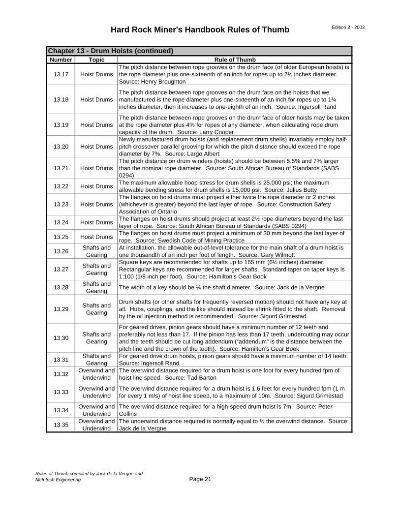
Hard Rock Miner's Handbook Rules of Thumb Edition 3 - 2003
Number Topic Rule of Thumb
13.17 Hoist DrumsThe pitch distance between rope grooves on the drum face (of older European hoists) is the rope diameter plus one-sixteenth of an inch for ropes up to 2½ inches diameter. Source: Henry Broughton
13.18 Hoist DrumsThe pitch distance between rope grooves on the drum face on the hoists that we manufactured is the rope diameter plus one-sixteenth of an inch for ropes up to 1¾ inches diameter, then it increases to one-eighth of an inch. Source: Ingersoll Rand
13.19 Hoist DrumsThe pitch distance between rope grooves on the drum face of older hoists may be taken at the rope diameter plus 4% for ropes of any diameter, when calculating rope drum capacity of the drum. Source: Larry Cooper
13.20 Hoist DrumsNewly manufactured drum hoists (and replacement drum shells) invariably employ half-pitch crossover parallel grooving for which the pitch distance should exceed the rope diameter by 7%. Source: Largo Albert
13.21 Hoist DrumsThe pitch distance on drum winders (hoists) should be between 5.5% and 7% larger than the nominal rope diameter. Source: South African Bureau of Standards (SABS 0294)
13.22 Hoist DrumsThe maximum allowable hoop stress for drum shells is 25,000 psi; the maximum allowable bending stress for drum shells is 15,000 psi. Source: Julius Butty
13.23 Hoist DrumsThe flanges on hoist drums must project either twice the rope diameter or 2 inches (whichever is greater) beyond the last layer of rope. Source: Construction Safety Association of Ontario
13.24 Hoist DrumsThe flanges on hoist drums should project at least 2½ rope diameters beyond the last layer of rope. Source: South African Bureau of Standards (SABS 0294)
13.25 Hoist DrumsThe flanges on hoist drums must project a minimum of 30 mm beyond the last layer of rope. Source: Swedish Code of Mining Practice
13.26Shafts and
GearingAt installation, the allowable out-of-level tolerance for the main shaft of a drum hoist is one thousandth of an inch per foot of length. Source: Gary Wilmott
13.27Shafts and
Gearing
Square keys are recommended for shafts up to 165 mm (6½ inches) diameter. Rectangular keys are recommended for larger shafts. Standard taper on taper keys is 1:100 (1/8 inch per foot). Source: Hamilton’s Gear Book
13.28Shafts and
GearingThe width of a key should be ¼ the shaft diameter. Source: Jack de la Vergne
13.29Shafts and
Gearing
Drum shafts (or other shafts for frequently reversed motion) should not have any key at all. Hubs, couplings, and the like should instead be shrink fitted to the shaft. Removal by the oil injection method is recommended. Source: Sigurd Grimestad
13.30Shafts and
Gearing
For geared drives, pinion gears should have a minimum number of 12 teeth and preferably not less than 17. If the pinion has less than 17 teeth, undercutting may occur and the teeth should be cut long addendum (“addendum” is the distance between the pitch line and the crown of the tooth). Source: Hamilton’s Gear Book
13.31Shafts and
GearingFor geared drive drum hoists, pinion gears should have a minimum number of 14 teeth. Source: Ingersoll Rand
13.32Overwind and
UnderwindThe overwind distance required for a drum hoist is one foot for every hundred fpm of hoist line speed. Source: Tad Barton
13.33Overwind and
UnderwindThe overwind distance required for a drum hoist is 1.6 feet for every hundred fpm (1 m for every 1 m/s) of hoist line speed, to a maximum of 10m. Source: Sigurd Grimestad
13.34Overwind and
UnderwindThe overwind distance required for a high-speed drum hoist is 7m. Source: Peter Collins
13.35Overwind and
UnderwindThe underwind distance required is normally equal to ½ the overwind distance. Source: Jack de la Vergne
Chapter 13 - Drum Hoists (continued)
Rules of Thumb compiled by Jack de la Vergne andMcIntosh Engineering Page 21
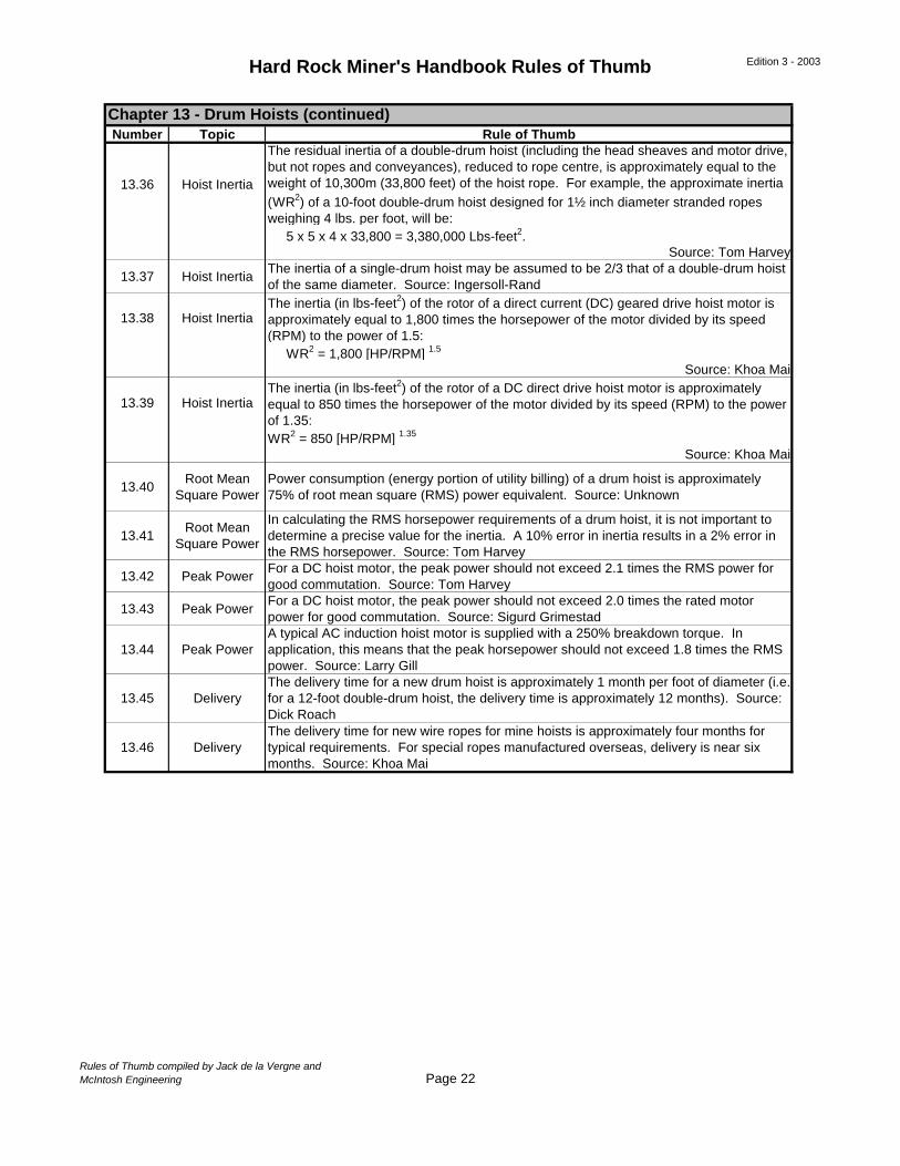
Hard Rock Miner's Handbook Rules of Thumb Edition 3 - 2003
Number Topic Rule of Thumb
13.36 Hoist Inertia
The residual inertia of a double-drum hoist (including the head sheaves and motor drive, but not ropes and conveyances), reduced to rope centre, is approximately equal to the weight of 10,300m (33,800 feet) of the hoist rope. For example, the approximate inertia (WR2) of a 10-foot double-drum hoist designed for 1½ inch diameter stranded ropes weighing 4 lbs. per foot, will be: 5 x 5 x 4 x 33,800 = 3,380,000 Lbs-feet2.
Source: Tom Harvey
13.37 Hoist InertiaThe inertia of a single-drum hoist may be assumed to be 2/3 that of a double-drum hoist of the same diameter. Source: Ingersoll-Rand
13.38 Hoist InertiaThe inertia (in lbs-feet2) of the rotor of a direct current (DC) geared drive hoist motor is approximately equal to 1,800 times the horsepower of the motor divided by its speed (RPM) to the power of 1.5: WR2 = 1,800 [HP/RPM] 1.5
Source: Khoa Mai
13.39 Hoist InertiaThe inertia (in lbs-feet2) of the rotor of a DC direct drive hoist motor is approximately equal to 850 times the horsepower of the motor divided by its speed (RPM) to the power of 1.35:WR2 = 850 [HP/RPM] 1.35
Source: Khoa Mai
13.40Root Mean
Square PowerPower consumption (energy portion of utility billing) of a drum hoist is approximately 75% of root mean square (RMS) power equivalent. Source: Unknown
13.41Root Mean
Square Power
In calculating the RMS horsepower requirements of a drum hoist, it is not important to determine a precise value for the inertia. A 10% error in inertia results in a 2% error in the RMS horsepower. Source: Tom Harvey
13.42 Peak PowerFor a DC hoist motor, the peak power should not exceed 2.1 times the RMS power for good commutation. Source: Tom Harvey
13.43 Peak PowerFor a DC hoist motor, the peak power should not exceed 2.0 times the rated motor power for good commutation. Source: Sigurd Grimestad
13.44 Peak PowerA typical AC induction hoist motor is supplied with a 250% breakdown torque. In application, this means that the peak horsepower should not exceed 1.8 times the RMS power. Source: Larry Gill
13.45 DeliveryThe delivery time for a new drum hoist is approximately 1 month per foot of diameter (i.e. for a 12-foot double-drum hoist, the delivery time is approximately 12 months). Source: Dick Roach
13.46 DeliveryThe delivery time for new wire ropes for mine hoists is approximately four months for typical requirements. For special ropes manufactured overseas, delivery is near six months. Source: Khoa Mai
Chapter 13 - Drum Hoists (continued)
Rules of Thumb compiled by Jack de la Vergne andMcIntosh Engineering Page 22
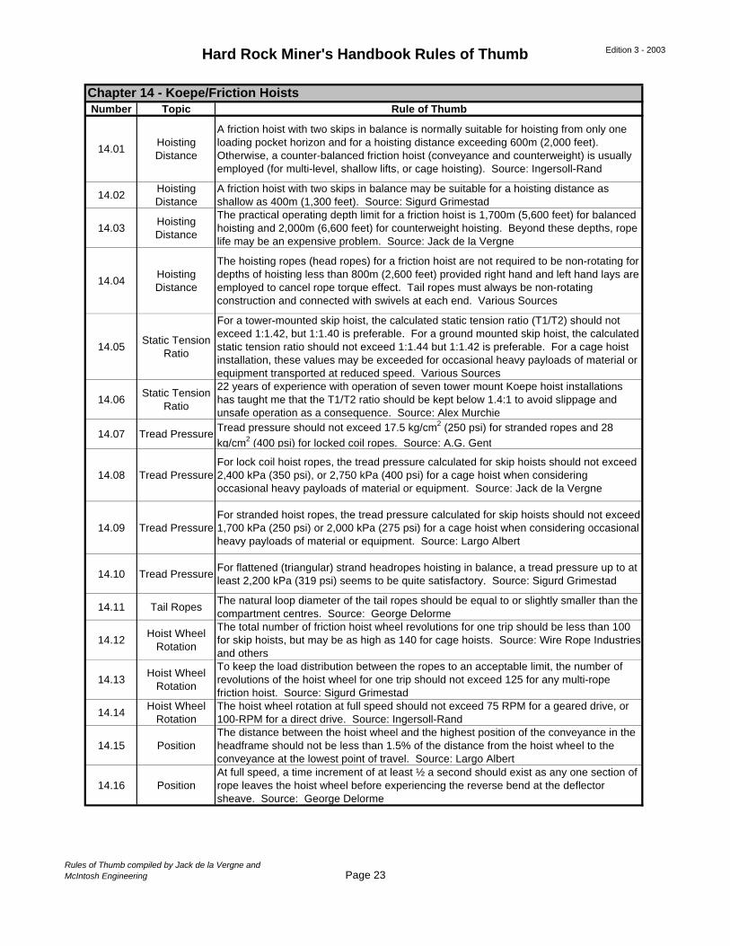
Hard Rock Miner's Handbook Rules of Thumb Edition 3 - 2003
Number Topic Rule of Thumb
14.01Hoisting Distance
A friction hoist with two skips in balance is normally suitable for hoisting from only one loading pocket horizon and for a hoisting distance exceeding 600m (2,000 feet). Otherwise, a counter-balanced friction hoist (conveyance and counterweight) is usually employed (for multi-level, shallow lifts, or cage hoisting). Source: Ingersoll-Rand
14.02Hoisting Distance
A friction hoist with two skips in balance may be suitable for a hoisting distance as shallow as 400m (1,300 feet). Source: Sigurd Grimestad
14.03Hoisting Distance
The practical operating depth limit for a friction hoist is 1,700m (5,600 feet) for balanced hoisting and 2,000m (6,600 feet) for counterweight hoisting. Beyond these depths, rope life may be an expensive problem. Source: Jack de la Vergne
14.04Hoisting Distance
The hoisting ropes (head ropes) for a friction hoist are not required to be non-rotating for depths of hoisting less than 800m (2,600 feet) provided right hand and left hand lays are employed to cancel rope torque effect. Tail ropes must always be non-rotating construction and connected with swivels at each end. Various Sources
14.05Static Tension
Ratio
For a tower-mounted skip hoist, the calculated static tension ratio (T1/T2) should not exceed 1:1.42, but 1:1.40 is preferable. For a ground mounted skip hoist, the calculated static tension ratio should not exceed 1:1.44 but 1:1.42 is preferable. For a cage hoist installation, these values may be exceeded for occasional heavy payloads of material or equipment transported at reduced speed. Various Sources
14.06Static Tension
Ratio
22 years of experience with operation of seven tower mount Koepe hoist installations has taught me that the T1/T2 ratio should be kept below 1.4:1 to avoid slippage and unsafe operation as a consequence. Source: Alex Murchie
14.07 Tread Pressure Tread pressure should not exceed 17.5 kg/cm2 (250 psi) for stranded ropes and 28 kg/cm2 (400 psi) for locked coil ropes. Source: A.G. Gent
14.08 Tread PressureFor lock coil hoist ropes, the tread pressure calculated for skip hoists should not exceed 2,400 kPa (350 psi), or 2,750 kPa (400 psi) for a cage hoist when considering occasional heavy payloads of material or equipment. Source: Jack de la Vergne
14.09 Tread PressureFor stranded hoist ropes, the tread pressure calculated for skip hoists should not exceed 1,700 kPa (250 psi) or 2,000 kPa (275 psi) for a cage hoist when considering occasional heavy payloads of material or equipment. Source: Largo Albert
14.10 Tread PressureFor flattened (triangular) strand headropes hoisting in balance, a tread pressure up to at least 2,200 kPa (319 psi) seems to be quite satisfactory. Source: Sigurd Grimestad
14.11 Tail RopesThe natural loop diameter of the tail ropes should be equal to or slightly smaller than the compartment centres. Source: George Delorme
14.12Hoist Wheel
Rotation
The total number of friction hoist wheel revolutions for one trip should be less than 100 for skip hoists, but may be as high as 140 for cage hoists. Source: Wire Rope Industries and others
14.13Hoist Wheel
Rotation
To keep the load distribution between the ropes to an acceptable limit, the number of revolutions of the hoist wheel for one trip should not exceed 125 for any multi-rope friction hoist. Source: Sigurd Grimestad
14.14Hoist Wheel
RotationThe hoist wheel rotation at full speed should not exceed 75 RPM for a geared drive, or 100-RPM for a direct drive. Source: Ingersoll-Rand
14.15 PositionThe distance between the hoist wheel and the highest position of the conveyance in the headframe should not be less than 1.5% of the distance from the hoist wheel to the conveyance at the lowest point of travel. Source: Largo Albert
14.16 PositionAt full speed, a time increment of at least ½ a second should exist as any one section of rope leaves the hoist wheel before experiencing the reverse bend at the deflector sheave. Source: George Delorme
Chapter 14 - Koepe/Friction Hoists
Rules of Thumb compiled by Jack de la Vergne andMcIntosh Engineering Page 23
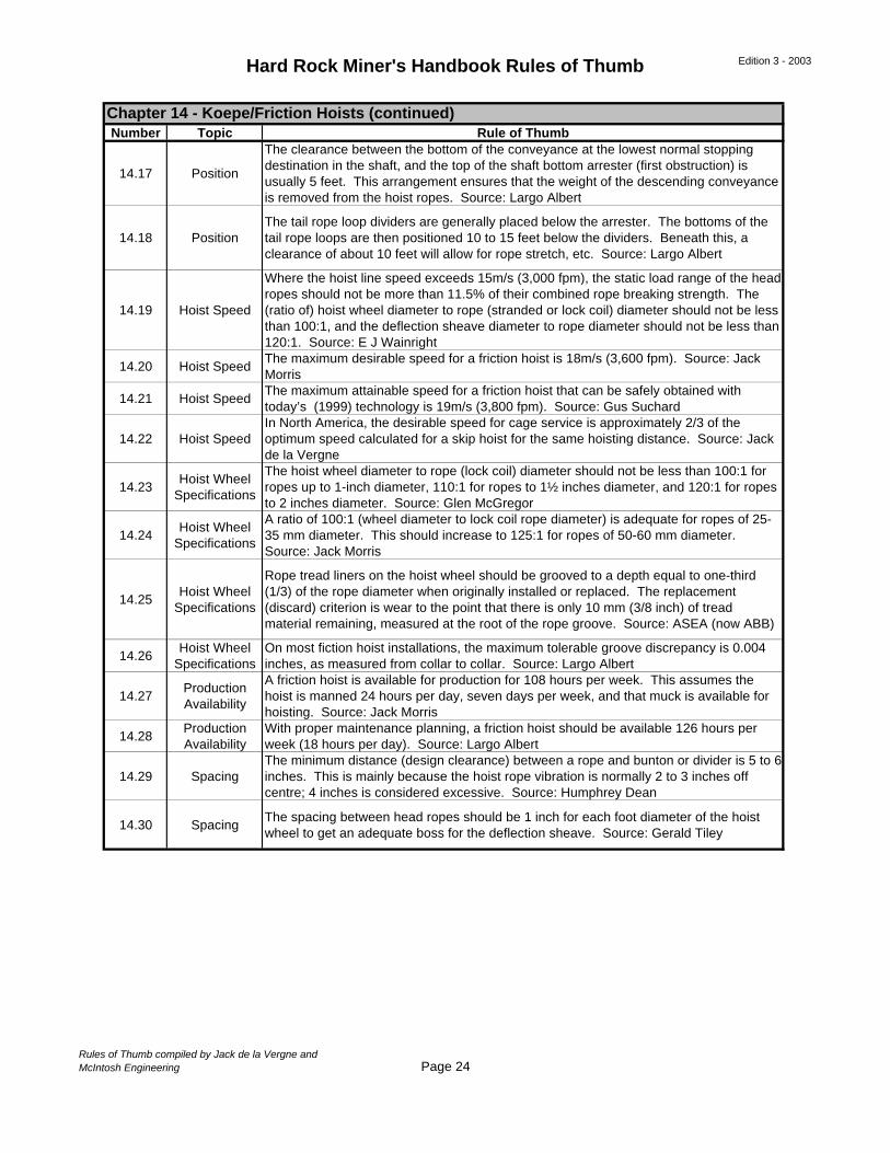
Hard Rock Miner's Handbook Rules of Thumb Edition 3 - 2003
Number Topic Rule of Thumb
14.17 Position
The clearance between the bottom of the conveyance at the lowest normal stopping destination in the shaft, and the top of the shaft bottom arrester (first obstruction) is usually 5 feet. This arrangement ensures that the weight of the descending conveyance is removed from the hoist ropes. Source: Largo Albert
14.18 PositionThe tail rope loop dividers are generally placed below the arrester. The bottoms of the tail rope loops are then positioned 10 to 15 feet below the dividers. Beneath this, a clearance of about 10 feet will allow for rope stretch, etc. Source: Largo Albert
14.19 Hoist Speed
Where the hoist line speed exceeds 15m/s (3,000 fpm), the static load range of the head ropes should not be more than 11.5% of their combined rope breaking strength. The (ratio of) hoist wheel diameter to rope (stranded or lock coil) diameter should not be less than 100:1, and the deflection sheave diameter to rope diameter should not be less than 120:1. Source: E J Wainright
14.20 Hoist SpeedThe maximum desirable speed for a friction hoist is 18m/s (3,600 fpm). Source: Jack Morris
14.21 Hoist SpeedThe maximum attainable speed for a friction hoist that can be safely obtained with today’s (1999) technology is 19m/s (3,800 fpm). Source: Gus Suchard
14.22 Hoist SpeedIn North America, the desirable speed for cage service is approximately 2/3 of the optimum speed calculated for a skip hoist for the same hoisting distance. Source: Jack de la Vergne
14.23Hoist Wheel
Specifications
The hoist wheel diameter to rope (lock coil) diameter should not be less than 100:1 for ropes up to 1-inch diameter, 110:1 for ropes to 1½ inches diameter, and 120:1 for ropes to 2 inches diameter. Source: Glen McGregor
14.24Hoist Wheel
Specifications
A ratio of 100:1 (wheel diameter to lock coil rope diameter) is adequate for ropes of 25-35 mm diameter. This should increase to 125:1 for ropes of 50-60 mm diameter. Source: Jack Morris
14.25Hoist Wheel
Specifications
Rope tread liners on the hoist wheel should be grooved to a depth equal to one-third (1/3) of the rope diameter when originally installed or replaced. The replacement (discard) criterion is wear to the point that there is only 10 mm (3/8 inch) of tread material remaining, measured at the root of the rope groove. Source: ASEA (now ABB)
14.26Hoist Wheel
SpecificationsOn most fiction hoist installations, the maximum tolerable groove discrepancy is 0.004 inches, as measured from collar to collar. Source: Largo Albert
14.27Production Availability
A friction hoist is available for production for 108 hours per week. This assumes the hoist is manned 24 hours per day, seven days per week, and that muck is available for hoisting. Source: Jack Morris
14.28Production Availability
With proper maintenance planning, a friction hoist should be available 126 hours per week (18 hours per day). Source: Largo Albert
14.29 SpacingThe minimum distance (design clearance) between a rope and bunton or divider is 5 to 6 inches. This is mainly because the hoist rope vibration is normally 2 to 3 inches off centre; 4 inches is considered excessive. Source: Humphrey Dean
14.30 SpacingThe spacing between head ropes should be 1 inch for each foot diameter of the hoist wheel to get an adequate boss for the deflection sheave. Source: Gerald Tiley
Chapter 14 - Koepe/Friction Hoists (continued)
Rules of Thumb compiled by Jack de la Vergne andMcIntosh Engineering Page 24
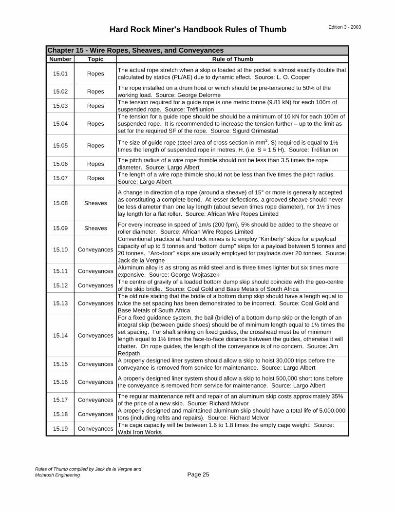
Hard Rock Miner's Handbook Rules of Thumb Edition 3 - 2003
Number Topic Rule of Thumb
15.01 Ropes The actual rope stretch when a skip is loaded at the pocket is almost exactly double that calculated by statics (PL/AE) due to dynamic effect. Source: L. O. Cooper
15.02 Ropes The rope installed on a drum hoist or winch should be pre-tensioned to 50% of the working load. Source: George Delorme
15.03 Ropes The tension required for a guide rope is one metric tonne (9.81 kN) for each 100m of suspended rope. Source: Tréfilunion
15.04 Ropes The tension for a guide rope should be should be a minimum of 10 kN for each 100m of suspended rope. It is recommended to increase the tension further – up to the limit as set for the required SF of the rope. Source: Sigurd Grimestad
15.05 Ropes The size of guide rope (steel area of cross section in mm2, S) required is equal to 1½ times the length of suspended rope in metres, H. (i.e. S = 1.5 H). Source: Tréfilunion
15.06 Ropes The pitch radius of a wire rope thimble should not be less than 3.5 times the rope diameter. Source: Largo Albert
15.07 Ropes The length of a wire rope thimble should not be less than five times the pitch radius. Source: Largo Albert
15.08 Sheaves
A change in direction of a rope (around a sheave) of 15° or more is generally accepted as constituting a complete bend. At lesser deflections, a grooved sheave should never be less diameter than one lay length (about seven times rope diameter), nor 1½ times lay length for a flat roller. Source: African Wire Ropes Limited
15.09 SheavesFor every increase in speed of 1m/s (200 fpm), 5% should be added to the sheave or roller diameter. Source: African Wire Ropes Limited
15.10 Conveyances
Conventional practice at hard rock mines is to employ “Kimberly” skips for a payload capacity of up to 5 tonnes and “bottom dump” skips for a payload between 5 tonnes and 20 tonnes. “Arc-door” skips are usually employed for payloads over 20 tonnes. Source: Jack de la Vergne
15.11 ConveyancesAluminum alloy is as strong as mild steel and is three times lighter but six times more expensive. Source: George Wojtaszek
15.12 ConveyancesThe centre of gravity of a loaded bottom dump skip should coincide with the geo-centre of the skip bridle. Source: Coal Gold and Base Metals of South Africa
15.13 ConveyancesThe old rule stating that the bridle of a bottom dump skip should have a length equal to twice the set spacing has been demonstrated to be incorrect. Source: Coal Gold and Base Metals of South Africa
15.14 Conveyances
For a fixed guidance system, the bail (bridle) of a bottom dump skip or the length of an integral skip (between guide shoes) should be of minimum length equal to 1½ times the set spacing. For shaft sinking on fixed guides, the crosshead must be of minimum length equal to 1½ times the face-to-face distance between the guides, otherwise it will chatter. On rope guides, the length of the conveyance is of no concern. Source: Jim Redpath
15.15 ConveyancesA properly designed liner system should allow a skip to hoist 30,000 trips before the conveyance is removed from service for maintenance. Source: Largo Albert
15.16 ConveyancesA properly designed liner system should allow a skip to hoist 500,000 short tons before the conveyance is removed from service for maintenance. Source: Largo Albert
15.17 ConveyancesThe regular maintenance refit and repair of an aluminum skip costs approximately 35% of the price of a new skip. Source: Richard McIvor
15.18 ConveyancesA properly designed and maintained aluminum skip should have a total life of 5,000,000 tons (including refits and repairs). Source: Richard McIvor
15.19 ConveyancesThe cage capacity will be between 1.6 to 1.8 times the empty cage weight. Source: Wabi Iron Works
Chapter 15 - Wire Ropes, Sheaves, and Conveyances
Rules of Thumb compiled by Jack de la Vergne andMcIntosh Engineering Page 25
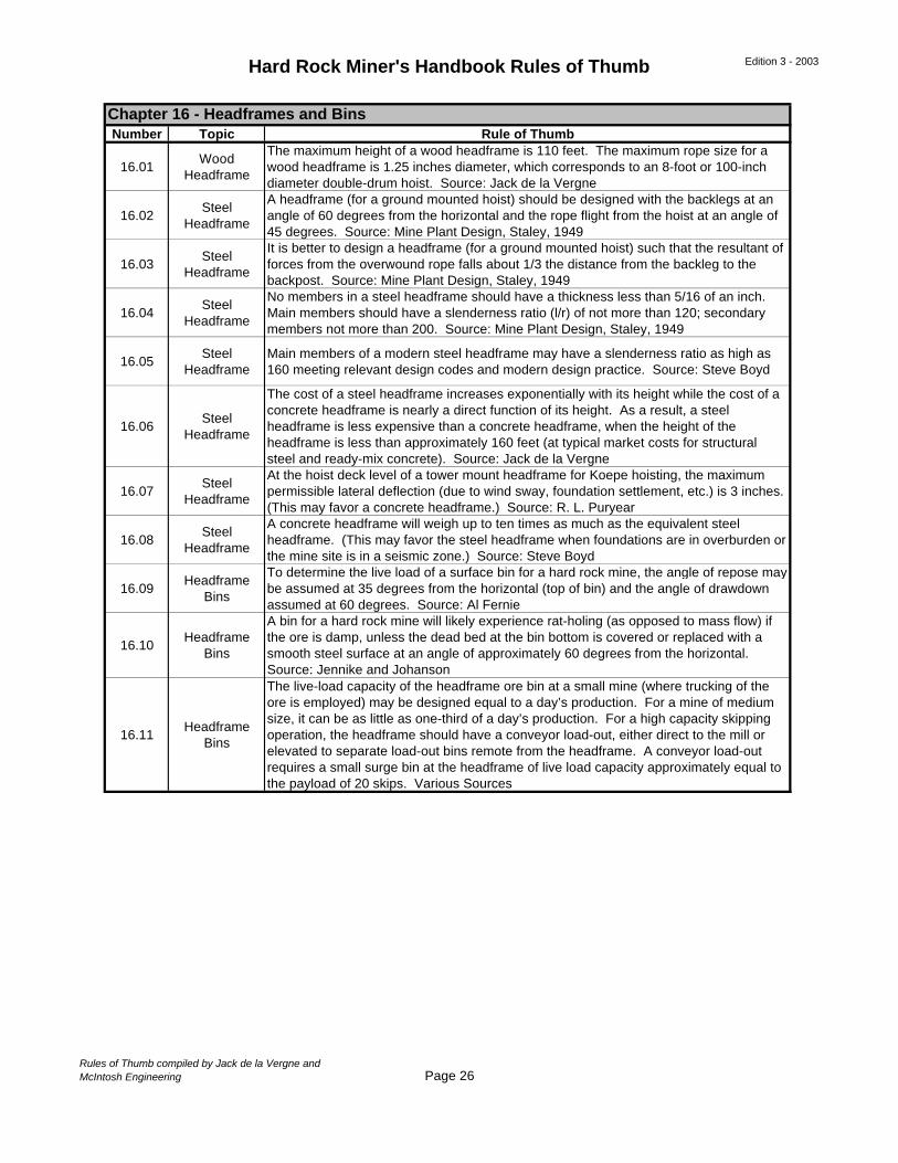
Hard Rock Miner's Handbook Rules of Thumb Edition 3 - 2003
Number Topic Rule of Thumb
16.01Wood
Headframe
The maximum height of a wood headframe is 110 feet. The maximum rope size for a wood headframe is 1.25 inches diameter, which corresponds to an 8-foot or 100-inch diameter double-drum hoist. Source: Jack de la Vergne
16.02Steel
Headframe
A headframe (for a ground mounted hoist) should be designed with the backlegs at an angle of 60 degrees from the horizontal and the rope flight from the hoist at an angle of 45 degrees. Source: Mine Plant Design, Staley, 1949
16.03Steel
Headframe
It is better to design a headframe (for a ground mounted hoist) such that the resultant of forces from the overwound rope falls about 1/3 the distance from the backleg to the backpost. Source: Mine Plant Design, Staley, 1949
16.04Steel
Headframe
No members in a steel headframe should have a thickness less than 5/16 of an inch. Main members should have a slenderness ratio (l/r) of not more than 120; secondary members not more than 200. Source: Mine Plant Design, Staley, 1949
16.05Steel
HeadframeMain members of a modern steel headframe may have a slenderness ratio as high as 160 meeting relevant design codes and modern design practice. Source: Steve Boyd
16.06Steel
Headframe
The cost of a steel headframe increases exponentially with its height while the cost of a concrete headframe is nearly a direct function of its height. As a result, a steel headframe is less expensive than a concrete headframe, when the height of the headframe is less than approximately 160 feet (at typical market costs for structural steel and ready-mix concrete). Source: Jack de la Vergne
16.07Steel
Headframe
At the hoist deck level of a tower mount headframe for Koepe hoisting, the maximum permissible lateral deflection (due to wind sway, foundation settlement, etc.) is 3 inches. (This may favor a concrete headframe.) Source: R. L. Puryear
16.08Steel
Headframe
A concrete headframe will weigh up to ten times as much as the equivalent steel headframe. (This may favor the steel headframe when foundations are in overburden or the mine site is in a seismic zone.) Source: Steve Boyd
16.09Headframe
Bins
To determine the live load of a surface bin for a hard rock mine, the angle of repose may be assumed at 35 degrees from the horizontal (top of bin) and the angle of drawdown assumed at 60 degrees. Source: Al Fernie
16.10Headframe
Bins
A bin for a hard rock mine will likely experience rat-holing (as opposed to mass flow) if the ore is damp, unless the dead bed at the bin bottom is covered or replaced with a smooth steel surface at an angle of approximately 60 degrees from the horizontal. Source: Jennike and Johanson
16.11Headframe
Bins
The live-load capacity of the headframe ore bin at a small mine (where trucking of the ore is employed) may be designed equal to a day’s production. For a mine of medium size, it can be as little as one-third of a day’s production. For a high capacity skipping operation, the headframe should have a conveyor load-out, either direct to the mill or elevated to separate load-out bins remote from the headframe. A conveyor load-out requires a small surge bin at the headframe of live load capacity approximately equal to the payload of 20 skips. Various Sources
Chapter 16 - Headframes and Bins
Rules of Thumb compiled by Jack de la Vergne andMcIntosh Engineering Page 26

Hard Rock Miner's Handbook Rules of Thumb Edition 3 - 2003
Number Topic Rule of Thumb
17.01 CostsAn underground mine is more economically served by a belt conveyor than railcars or trucks when the daily mine production exceeds 5,000 tons. Source: Al Fernie
17.02 CostsAs a rule, a belt conveyor operation is more economical than truck haulage if the conveying distance exceeds 1 kilometer (3,280 feet). Source: Heinz Altoff
17.03 CostsThe ton-mile cost of transport by belt conveyor may be as low as one-tenth the cost by haul truck. Source: Robert Schmidt
17.04 CostsThe installed capital cost of a long belt conveyor system to be put underground is approximately equal to the cost of driving the heading in which it is to be placed. Source: Jack de la Vergne
17.05 CostsOperating maintenance cost per year for a belt conveyor is 2% of the purchase cost of equipment plus 5% of the belt cost. To this should be added belt replacement every five to 15 years (five for underground hard rock mines). Source: Hans Nauman
17.06Feed and Feeders
In a hard rock mine, the product from a jaw crusher to feed a conveyor belt will have a size distribution such that the -80% fraction size is slightly less than the open side setting of the crusher. For example, if the open side setting of the underground jaw crusher is 6 inches, then the d80 product size = 5¾ inches. Source: Unknown
17.07Feed and Feeders
For an apron feeder, the bed depth of material fed should be uniform and equal to one-half the width of the feeder. Source: Dave Assinck
17.08Feed and Feeders
A vibratory feeder is best designed for a bed depth of about half its width. Source: Bill Potma
17.09Feed and Feeders
The free fall of crushed ore to a belt must not exceed 4 feet. Chutes, baffles, or rock boxes should be employed to reduce impact and save belt life. Source: Heinz Schober
17.10Feed and Feeders
The horsepower requirements for apron feeders listed by manufacturers are generally low. They should be increased by a factor of 30 to 50% to take into account considerations like starting torque, starting when cold, when the bearings are sticky, and when the bearings become worn. Source: Reisner and Rothe
17.11Feed and Feeders
Power requirements for apron feeders are about twice as high as for comparable belt feeders. Source: Reisner and Rothe
17.12Feed and Feeders
A well-designed jaw crusher installation has the lip of the chute overlapping the throat of the vibrating feeder by 400 mm (16 inches) to prevent spill resulting from the inevitable blowback of wayward fines. Source: Jean Beliveau
17.13Feed and Feeders
75-90% of belt wear occurs at the loading points. Source: Lawrence Adler
17.14Belt Conveyor
Design
On well-engineered systems, using appropriate controls to limit acceleration, the (static) factor of safety for belt tension can be reduced from 10:1 to 8:1 for fabric belts and from 7:1 to 6:1 for steel cord belts. Source: D. T. Price
17.15Belt Conveyor
Design
The standard troughing angles in North America are 20, 35, and 45 degrees. In Europe, they are 20, 30, and 40 degrees. A 20-degree troughing angle permits the use of the thickest belts, so the heaviest material and maximum lump size can be carried. A troughing angle of 35 degrees is typically employed for conveying crushed ore. Source: Unknown
17.16Belt Conveyor
Design
For conveying crushed ore, the cross-section of the material load on the belt can usually be accurately calculated using a 20-degree surcharge angle. It should be considered that when conveying over a long distance, the dynamic settling of the load could reduce the surcharge angle to 15 degrees. Source: Al Firnie
Chapter 17 - Conveyors and Feeders
Rules of Thumb compiled by Jack de la Vergne andMcIntosh Engineering Page 27
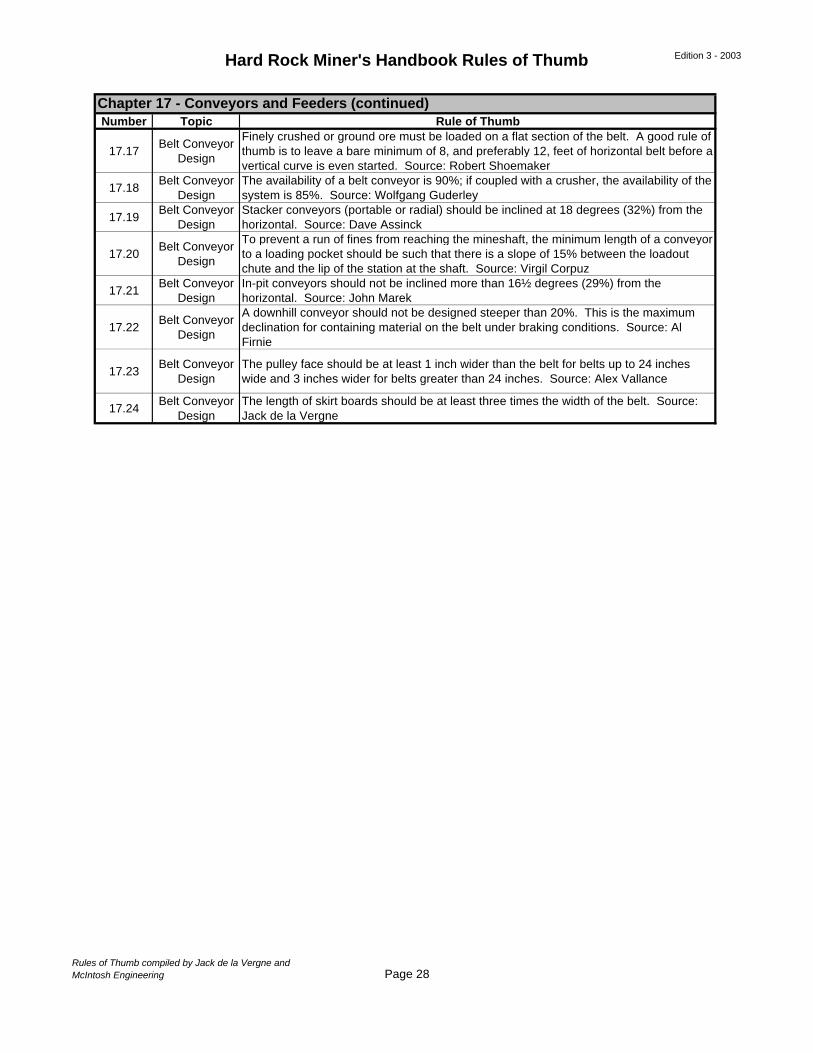
Hard Rock Miner's Handbook Rules of Thumb Edition 3 - 2003
Number Topic Rule of Thumb
17.17Belt Conveyor
Design
Finely crushed or ground ore must be loaded on a flat section of the belt. A good rule of thumb is to leave a bare minimum of 8, and preferably 12, feet of horizontal belt before a vertical curve is even started. Source: Robert Shoemaker
17.18Belt Conveyor
DesignThe availability of a belt conveyor is 90%; if coupled with a crusher, the availability of the system is 85%. Source: Wolfgang Guderley
17.19Belt Conveyor
DesignStacker conveyors (portable or radial) should be inclined at 18 degrees (32%) from the horizontal. Source: Dave Assinck
17.20Belt Conveyor
Design
To prevent a run of fines from reaching the mineshaft, the minimum length of a conveyor to a loading pocket should be such that there is a slope of 15% between the loadout chute and the lip of the station at the shaft. Source: Virgil Corpuz
17.21Belt Conveyor
DesignIn-pit conveyors should not be inclined more than 16½ degrees (29%) from the horizontal. Source: John Marek
17.22Belt Conveyor
Design
A downhill conveyor should not be designed steeper than 20%. This is the maximum declination for containing material on the belt under braking conditions. Source: Al Firnie
17.23Belt Conveyor
DesignThe pulley face should be at least 1 inch wider than the belt for belts up to 24 inches wide and 3 inches wider for belts greater than 24 inches. Source: Alex Vallance
17.24Belt Conveyor
DesignThe length of skirt boards should be at least three times the width of the belt. Source: Jack de la Vergne
Chapter 17 - Conveyors and Feeders (continued)
Rules of Thumb compiled by Jack de la Vergne andMcIntosh Engineering Page 28
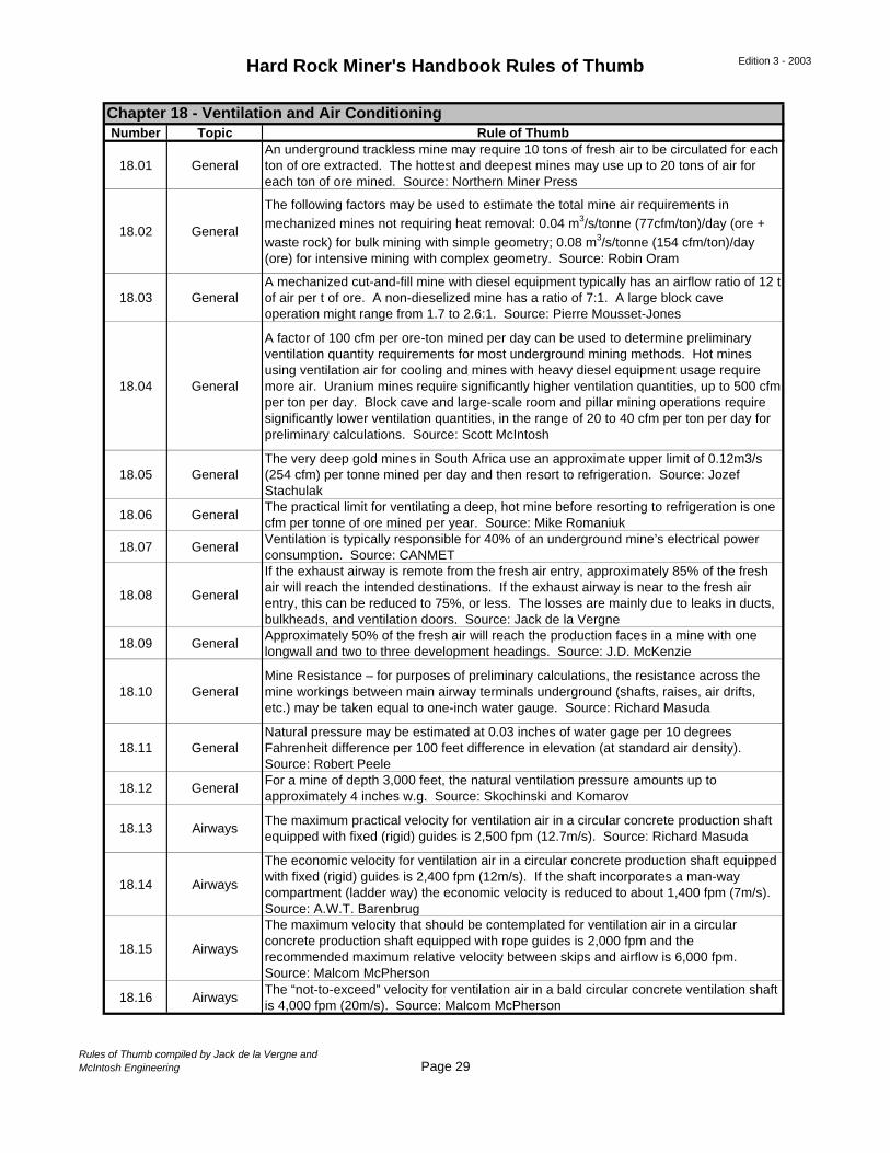
Hard Rock Miner's Handbook Rules of Thumb Edition 3 - 2003
Number Topic Rule of Thumb
18.01 GeneralAn underground trackless mine may require 10 tons of fresh air to be circulated for each ton of ore extracted. The hottest and deepest mines may use up to 20 tons of air for each ton of ore mined. Source: Northern Miner Press
18.02 General
The following factors may be used to estimate the total mine air requirements in mechanized mines not requiring heat removal: 0.04 m3/s/tonne (77cfm/ton)/day (ore + waste rock) for bulk mining with simple geometry; 0.08 m3/s/tonne (154 cfm/ton)/day (ore) for intensive mining with complex geometry. Source: Robin Oram
18.03 GeneralA mechanized cut-and-fill mine with diesel equipment typically has an airflow ratio of 12 t of air per t of ore. A non-dieselized mine has a ratio of 7:1. A large block cave operation might range from 1.7 to 2.6:1. Source: Pierre Mousset-Jones
18.04 General
A factor of 100 cfm per ore-ton mined per day can be used to determine preliminary ventilation quantity requirements for most underground mining methods. Hot mines using ventilation air for cooling and mines with heavy diesel equipment usage require more air. Uranium mines require significantly higher ventilation quantities, up to 500 cfm per ton per day. Block cave and large-scale room and pillar mining operations require significantly lower ventilation quantities, in the range of 20 to 40 cfm per ton per day for preliminary calculations. Source: Scott McIntosh
18.05 GeneralThe very deep gold mines in South Africa use an approximate upper limit of 0.12m3/s (254 cfm) per tonne mined per day and then resort to refrigeration. Source: Jozef Stachulak
18.06 GeneralThe practical limit for ventilating a deep, hot mine before resorting to refrigeration is one cfm per tonne of ore mined per year. Source: Mike Romaniuk
18.07 GeneralVentilation is typically responsible for 40% of an underground mine’s electrical power consumption. Source: CANMET
18.08 General
If the exhaust airway is remote from the fresh air entry, approximately 85% of the fresh air will reach the intended destinations. If the exhaust airway is near to the fresh air entry, this can be reduced to 75%, or less. The losses are mainly due to leaks in ducts, bulkheads, and ventilation doors. Source: Jack de la Vergne
18.09 GeneralApproximately 50% of the fresh air will reach the production faces in a mine with one longwall and two to three development headings. Source: J.D. McKenzie
18.10 GeneralMine Resistance – for purposes of preliminary calculations, the resistance across the mine workings between main airway terminals underground (shafts, raises, air drifts, etc.) may be taken equal to one-inch water gauge. Source: Richard Masuda
18.11 GeneralNatural pressure may be estimated at 0.03 inches of water gage per 10 degrees Fahrenheit difference per 100 feet difference in elevation (at standard air density). Source: Robert Peele
18.12 GeneralFor a mine of depth 3,000 feet, the natural ventilation pressure amounts up to approximately 4 inches w.g. Source: Skochinski and Komarov
18.13 AirwaysThe maximum practical velocity for ventilation air in a circular concrete production shaft equipped with fixed (rigid) guides is 2,500 fpm (12.7m/s). Source: Richard Masuda
18.14 Airways
The economic velocity for ventilation air in a circular concrete production shaft equipped with fixed (rigid) guides is 2,400 fpm (12m/s). If the shaft incorporates a man-way compartment (ladder way) the economic velocity is reduced to about 1,400 fpm (7m/s). Source: A.W.T. Barenbrug
18.15 Airways
The maximum velocity that should be contemplated for ventilation air in a circular concrete production shaft equipped with rope guides is 2,000 fpm and the recommended maximum relative velocity between skips and airflow is 6,000 fpm. Source: Malcom McPherson
18.16 AirwaysThe “not-to-exceed” velocity for ventilation air in a bald circular concrete ventilation shaft is 4,000 fpm (20m/s). Source: Malcom McPherson
Chapter 18 - Ventilation and Air Conditioning
Rules of Thumb compiled by Jack de la Vergne andMcIntosh Engineering Page 29
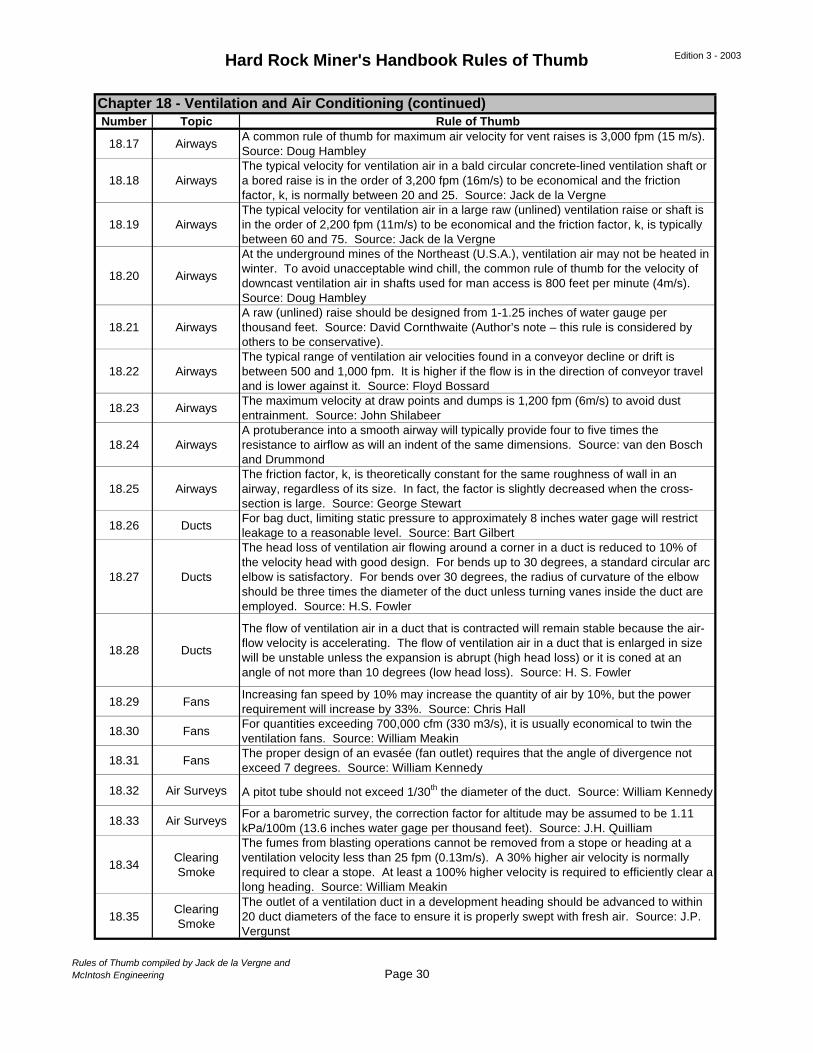
Hard Rock Miner's Handbook Rules of Thumb Edition 3 - 2003
Number Topic Rule of Thumb
18.17 AirwaysA common rule of thumb for maximum air velocity for vent raises is 3,000 fpm (15 m/s). Source: Doug Hambley
18.18 AirwaysThe typical velocity for ventilation air in a bald circular concrete-lined ventilation shaft or a bored raise is in the order of 3,200 fpm (16m/s) to be economical and the friction factor, k, is normally between 20 and 25. Source: Jack de la Vergne
18.19 AirwaysThe typical velocity for ventilation air in a large raw (unlined) ventilation raise or shaft is in the order of 2,200 fpm (11m/s) to be economical and the friction factor, k, is typically between 60 and 75. Source: Jack de la Vergne
18.20 Airways
At the underground mines of the Northeast (U.S.A.), ventilation air may not be heated in winter. To avoid unacceptable wind chill, the common rule of thumb for the velocity of downcast ventilation air in shafts used for man access is 800 feet per minute (4m/s). Source: Doug Hambley
18.21 AirwaysA raw (unlined) raise should be designed from 1-1.25 inches of water gauge per thousand feet. Source: David Cornthwaite (Author’s note – this rule is considered by others to be conservative).
18.22 AirwaysThe typical range of ventilation air velocities found in a conveyor decline or drift is between 500 and 1,000 fpm. It is higher if the flow is in the direction of conveyor travel and is lower against it. Source: Floyd Bossard
18.23 AirwaysThe maximum velocity at draw points and dumps is 1,200 fpm (6m/s) to avoid dust entrainment. Source: John Shilabeer
18.24 AirwaysA protuberance into a smooth airway will typically provide four to five times the resistance to airflow as will an indent of the same dimensions. Source: van den Bosch and Drummond
18.25 AirwaysThe friction factor, k, is theoretically constant for the same roughness of wall in an airway, regardless of its size. In fact, the factor is slightly decreased when the cross-section is large. Source: George Stewart
18.26 DuctsFor bag duct, limiting static pressure to approximately 8 inches water gage will restrict leakage to a reasonable level. Source: Bart Gilbert
18.27 Ducts
The head loss of ventilation air flowing around a corner in a duct is reduced to 10% of the velocity head with good design. For bends up to 30 degrees, a standard circular arc elbow is satisfactory. For bends over 30 degrees, the radius of curvature of the elbow should be three times the diameter of the duct unless turning vanes inside the duct are employed. Source: H.S. Fowler
18.28 Ducts
The flow of ventilation air in a duct that is contracted will remain stable because the air-flow velocity is accelerating. The flow of ventilation air in a duct that is enlarged in size will be unstable unless the expansion is abrupt (high head loss) or it is coned at an angle of not more than 10 degrees (low head loss). Source: H. S. Fowler
18.29 FansIncreasing fan speed by 10% may increase the quantity of air by 10%, but the power requirement will increase by 33%. Source: Chris Hall
18.30 FansFor quantities exceeding 700,000 cfm (330 m3/s), it is usually economical to twin the ventilation fans. Source: William Meakin
18.31 FansThe proper design of an evasée (fan outlet) requires that the angle of divergence not exceed 7 degrees. Source: William Kennedy
18.32 Air Surveys A pitot tube should not exceed 1/30th the diameter of the duct. Source: William Kennedy
18.33 Air SurveysFor a barometric survey, the correction factor for altitude may be assumed to be 1.11 kPa/100m (13.6 inches water gage per thousand feet). Source: J.H. Quilliam
18.34Clearing Smoke
The fumes from blasting operations cannot be removed from a stope or heading at a ventilation velocity less than 25 fpm (0.13m/s). A 30% higher air velocity is normally required to clear a stope. At least a 100% higher velocity is required to efficiently clear a long heading. Source: William Meakin
18.35Clearing Smoke
The outlet of a ventilation duct in a development heading should be advanced to within 20 duct diameters of the face to ensure it is properly swept with fresh air. Source: J.P. Vergunst
Chapter 18 - Ventilation and Air Conditioning (continued)
Rules of Thumb compiled by Jack de la Vergne andMcIntosh Engineering Page 30
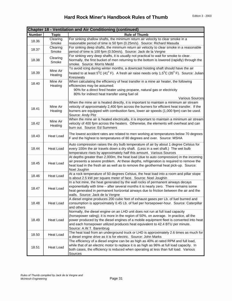
Hard Rock Miner's Handbook Rules of Thumb Edition 3 - 2003
Number Topic Rule of Thumb
18.36Clearing Smoke
For sinking shallow shafts, the minimum return air velocity to clear smoke in a reasonable period of time is 50 fpm (0.25m/s). Source: Richard Masuda
18.37Clearing Smoke
For sinking deep shafts, the minimum return air velocity to clear smoke in a reasonable period of time is 100 fpm (0.50m/s). Source: Jack de la Vergne
18.38Clearing Smoke
For sinking very deep shafts, it is usually not practical to wait for smoke to clear. Normally, the first bucket of men returning to the bottom is lowered (rapidly) through the smoke. Source: Morris Medd
18.39Mine Air Heating
To avoid icing during winter months, a downcast hoisting shaft should have the air heated to at least 50C (410 F). A fresh air raise needs only 1.50C (350 F). Source: Julian Kresowaty
18.40Mine Air Heating
When calculating the efficiency of heat transfer in a mine air heater, the following efficiencies may be assumed. 90% for a direct fired heater using propane, natural gas or electricity 80% for indirect heat transfer using fuel oil
Various Sources
18.41Mine Air Heating
When the mine air is heated directly, it is important to maintain a minimum air stream velocity of approximately 2,400 fpm across the burners for efficient heat transfer. If the burners are equipped with combustion fans, lower air speeds (1,000 fpm) can be used. Source: Andy Pitz
18.42Mine Air Heating
When the mine air is heated electrically, it is important to maintain a minimum air stream velocity of 400 fpm across the heaters. Otherwise, the elements will overheat and can burn out. Source: Ed Summers
18.43 Heat LoadThe lowest accident rates are related to men working at temperatures below 70 degrees F and the highest to temperatures of 80 degrees and over. Source: MSHA
18.44 Heat LoadAuto compression raises the dry bulb temperature of air by about 1 degree Celsius for every 100m the air travels down a dry shaft. (Less in a wet shaft.) The wet bulb temperature rises by approximately half this amount. Various Sources
18.45 Heat Load
At depths greater than 2,000m, the heat load (due to auto compression) in the incoming air presents a severe problem. At these depths, refrigeration is required to remove the heat load in the fresh air as well as to remove the geothermal heat pick-up. Source: Noel Joughin
18.46 Heat LoadAt a rock temperature of 50 degrees Celsius, the heat load into a room and pillar stope is about 2.5 kW per square meter of face. Source: Noel Joughin
18.47 Heat Load
In a hot mine, the heat generated by the wall rocks of permanent airways decays exponentially with time – after several months it is nearly zero. There remains some heat generated in permanent horizontal airways due to friction between the air and the walls. Source: Jack de la Vergne
18.48 Heat LoadA diesel engine produces 200 cubic feet of exhaust gases per Lb. of fuel burned and consumption is approximately 0.45 Lb. of fuel per horsepower-hour. Source: Caterpillar and others
18.49 Heat Load
Normally, the diesel engine on an LHD unit does not run at full load capacity (horsepower rating); it is more in the region of 50%, on average. In practice, all the power produced by the diesel engines of a mobile equipment fleet is converted into heat and each horsepower utilized produces heat equivalent to 42.4 BTU per minute. Source: A.W.T. Barenbrug
18.50 Heat LoadThe heat load from an underground truck or LHD is approximately 2.6 times as much for a diesel engine drive as it is for electric. Source: John Marks
18.51 Heat Load
The efficiency of a diesel engine can be as high as 40% at rated RPM and full load, while that of an electric motor to replace it is as high as 96% at full load capacity. In both cases, the efficiency is reduced when operating at less than full load. Various Sources
Chapter 18 - Ventilation and Air Conditioning (continued)
Rules of Thumb compiled by Jack de la Vergne andMcIntosh Engineering Page 31
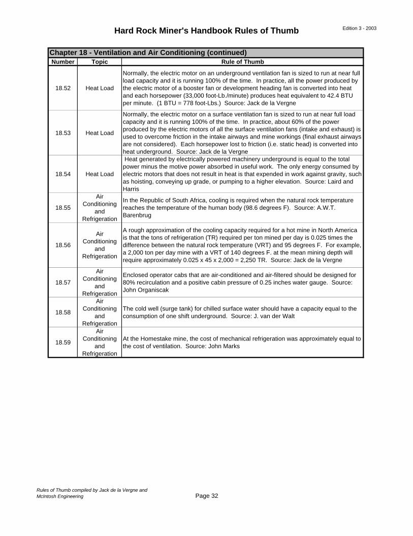
Hard Rock Miner's Handbook Rules of Thumb Edition 3 - 2003
Number Topic Rule of Thumb
18.52 Heat Load
Normally, the electric motor on an underground ventilation fan is sized to run at near full load capacity and it is running 100% of the time. In practice, all the power produced by the electric motor of a booster fan or development heading fan is converted into heat and each horsepower (33,000 foot-Lb./minute) produces heat equivalent to 42.4 BTU per minute. (1 BTU = 778 foot-Lbs.) Source: Jack de la Vergne
18.53 Heat Load
Normally, the electric motor on a surface ventilation fan is sized to run at near full load capacity and it is running 100% of the time. In practice, about 60% of the power produced by the electric motors of all the surface ventilation fans (intake and exhaust) is used to overcome friction in the intake airways and mine workings (final exhaust airways are not considered). Each horsepower lost to friction (i.e. static head) is converted into heat underground. Source: Jack de la Vergne
18.54 Heat Load
Heat generated by electrically powered machinery underground is equal to the total power minus the motive power absorbed in useful work. The only energy consumed by electric motors that does not result in heat is that expended in work against gravity, such as hoisting, conveying up grade, or pumping to a higher elevation. Source: Laird and Harris
18.55
Air Conditioning
and Refrigeration
In the Republic of South Africa, cooling is required when the natural rock temperature reaches the temperature of the human body (98.6 degrees F). Source: A.W.T. Barenbrug
18.56
Air Conditioning
and Refrigeration
A rough approximation of the cooling capacity required for a hot mine in North America is that the tons of refrigeration (TR) required per ton mined per day is 0.025 times the difference between the natural rock temperature (VRT) and 95 degrees F. For example, a 2,000 ton per day mine with a VRT of 140 degrees F. at the mean mining depth will require approximately 0.025 x 45 x 2,000 = 2,250 TR. Source: Jack de la Vergne
18.57
Air Conditioning
and Refrigeration
Enclosed operator cabs that are air-conditioned and air-filtered should be designed for 80% recirculation and a positive cabin pressure of 0.25 inches water gauge. Source: John Organiscak
18.58
Air Conditioning
and Refrigeration
The cold well (surge tank) for chilled surface water should have a capacity equal to the consumption of one shift underground. Source: J. van der Walt
18.59
Air Conditioning
and Refrigeration
At the Homestake mine, the cost of mechanical refrigeration was approximately equal to the cost of ventilation. Source: John Marks
Chapter 18 - Ventilation and Air Conditioning (continued)
Rules of Thumb compiled by Jack de la Vergne andMcIntosh Engineering Page 32
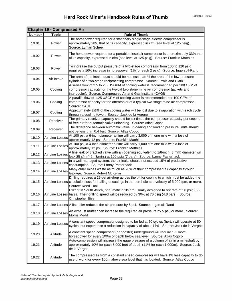
Hard Rock Miner's Handbook Rules of Thumb Edition 3 - 2003
Number Topic Rule of Thumb
19.01 PowerThe horsepower required for a stationary single-stage electric compressor is approximately 28% that of its capacity, expressed in cfm (sea level at 125 psig). Source: Lyman Scheel
19.02 PowerThe horsepower required for a portable diesel air compressor is approximately 33% that of its capacity, expressed in cfm (sea level at 125 psig). Source: Franklin Matthias
19.03 PowerTo increase the output pressure of a two-stage compressor from 100 to 120 psig requires a 10% increase in horsepower (1% for each 2 psig). Source: Ingersoll-Rand
19.04 Air IntakeThe area of the intake duct should be not less than ½ the area of the low-pressure cylinder of a two-stage reciprocating compressor. Source: Lewis and Clark
19.05 CoolingA series flow of 2.5 to 2.8 USGPM of cooling water is recommended per 100 CFM of compressor capacity for the typical two-stage mine air compressor (jackets and intercooler). Source: Compressed Air and Gas Institute (CAGI)
19.06 CoolingA parallel flow of 1.25 USGPM of cooling water is recommended per 100 CFM of compressor capacity for the aftercooler of a typical two-stage mine air compressor. Source: CAGI
19.07 CoolingApproximately 2½% of the cooling water will be lost due to evaporation with each cycle through a cooling tower. Source: Jack de la Vergne
19.08 ReceiverThe primary receiver capacity should be six times the compressor capacity per second of free air for automatic valve unloading. Source: Atlas Copco
19.09 ReceiverThe difference between automatic valve unloading and loading pressure limits should not be less than 0.4 bar. Source: Atlas Copco
19.10 Air Line LossesAt 100 psi, a 6-inch diameter airline will carry 3,000 cfm one mile with a loss of approximately 12 psi. Source: Franklin Matthias
19.11 Air Line LossesAt 100 psi, a 4-inch diameter airline will carry 1,000 cfm one mile with a loss of approximately 12 psi. Source: Franklin Matthias
19.12 Air Line LossesA line leak or cracked valve with an opening equivalent to 1/8-inch (3 mm) diameter will leak 25 cfm (42m3/min.) at 100 psig (7 bars). Source: Lanny Pasternack
19.13 Air Line LossesIn a well-managed system, the air leaks should not exceed 15% of productive consumption. Source: Lanny Pasternack
19.14 Air Line LossesMany older mines waste as much as 70% of their compressed air capacity through leakage. Source: Robert McKellar
19.15 Air Line LossesDrilling requires a 25-psi air-drop across the bit for cooling to which must be added the circulation loss for bailing of cuttings in the borehole at a velocity of 5,000 fpm, or more. Source: Reed Tool
19.16 Air Line LossesExcept in South Africa, pneumatic drills are usually designed to operate at 90 psig (6.2 bars). Their drilling speed will be reduced by 30% at 70 psig (4.8 bars). Source: Christopher Bise
19.17 Air Line Losses A line oiler reduces the air pressure by 5 psi. Source: Ingersoll-Rand
19.18 Air Line LossesAn exhaust muffler can increase the required air pressure by 5 psi, or more. Source: Morris Medd
19.19 Air Line LossesA constant speed compressor designed to be fed at 60 cycles (hertz) will operate at 50 cycles, but experience a reduction in capacity of about 17%. Source: Jack de la Vergne
19.20 AltitudeA constant speed compressor (or booster) underground will require 1% more horsepower for every 100m of depth below sea level. Source: Atlas Copco
19.21 AltitudeAuto-compression will increase the gage pressure of a column of air in a mineshaft by approximately 10% for each 3,000 feet of depth (11% for each 1,000m). Source: Jack de la Vergne
19.22 AltitudeThe compressed air from a constant speed compressor will have 1% less capacity to do useful work for every 100m above sea level that it is located. Source: Atlas Copco
Chapter 19 - Compressed Air
Rules of Thumb compiled by Jack de la Vergne andMcIntosh Engineering Page 33
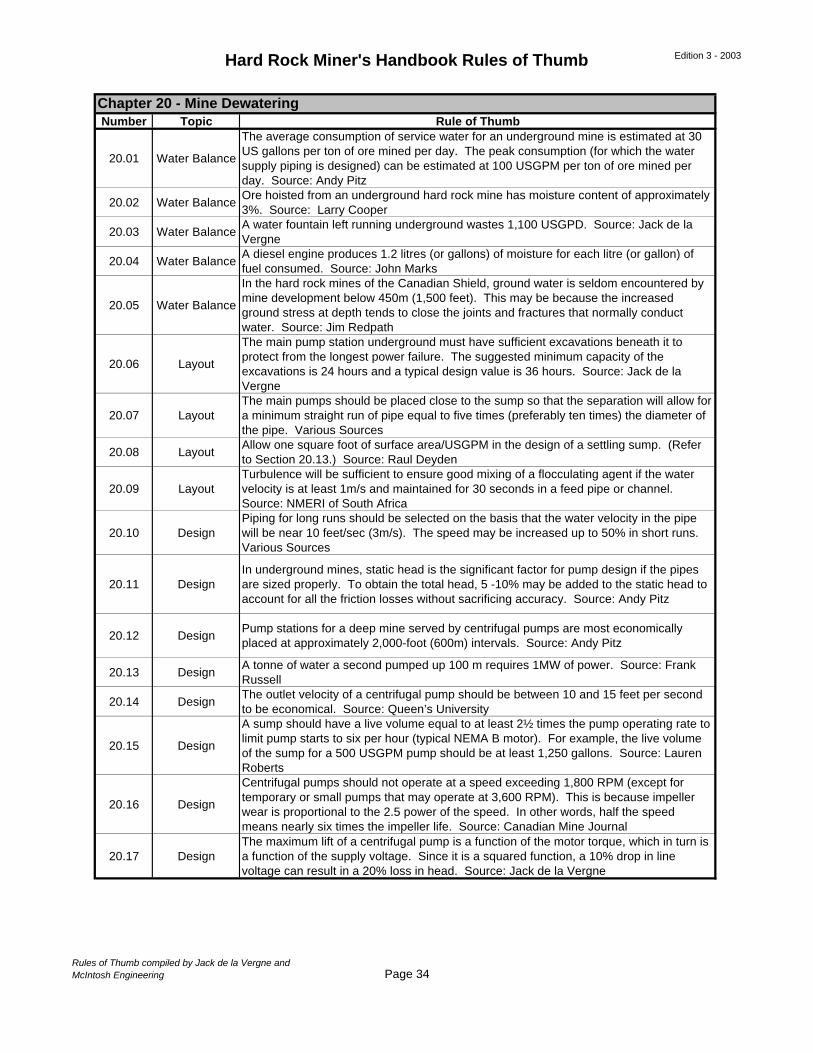
Hard Rock Miner's Handbook Rules of Thumb Edition 3 - 2003
Number Topic Rule of Thumb
20.01 Water Balance
The average consumption of service water for an underground mine is estimated at 30 US gallons per ton of ore mined per day. The peak consumption (for which the water supply piping is designed) can be estimated at 100 USGPM per ton of ore mined per day. Source: Andy Pitz
20.02 Water BalanceOre hoisted from an underground hard rock mine has moisture content of approximately 3%. Source: Larry Cooper
20.03 Water BalanceA water fountain left running underground wastes 1,100 USGPD. Source: Jack de la Vergne
20.04 Water BalanceA diesel engine produces 1.2 litres (or gallons) of moisture for each litre (or gallon) of fuel consumed. Source: John Marks
20.05 Water Balance
In the hard rock mines of the Canadian Shield, ground water is seldom encountered by mine development below 450m (1,500 feet). This may be because the increased ground stress at depth tends to close the joints and fractures that normally conduct water. Source: Jim Redpath
20.06 Layout
The main pump station underground must have sufficient excavations beneath it to protect from the longest power failure. The suggested minimum capacity of the excavations is 24 hours and a typical design value is 36 hours. Source: Jack de la Vergne
20.07 LayoutThe main pumps should be placed close to the sump so that the separation will allow for a minimum straight run of pipe equal to five times (preferably ten times) the diameter of the pipe. Various Sources
20.08 LayoutAllow one square foot of surface area/USGPM in the design of a settling sump. (Refer to Section 20.13.) Source: Raul Deyden
20.09 LayoutTurbulence will be sufficient to ensure good mixing of a flocculating agent if the water velocity is at least 1m/s and maintained for 30 seconds in a feed pipe or channel. Source: NMERI of South Africa
20.10 DesignPiping for long runs should be selected on the basis that the water velocity in the pipe will be near 10 feet/sec (3m/s). The speed may be increased up to 50% in short runs. Various Sources
20.11 DesignIn underground mines, static head is the significant factor for pump design if the pipes are sized properly. To obtain the total head, 5 -10% may be added to the static head to account for all the friction losses without sacrificing accuracy. Source: Andy Pitz
20.12 DesignPump stations for a deep mine served by centrifugal pumps are most economically placed at approximately 2,000-foot (600m) intervals. Source: Andy Pitz
20.13 DesignA tonne of water a second pumped up 100 m requires 1MW of power. Source: Frank Russell
20.14 DesignThe outlet velocity of a centrifugal pump should be between 10 and 15 feet per second to be economical. Source: Queen’s University
20.15 Design
A sump should have a live volume equal to at least 2½ times the pump operating rate to limit pump starts to six per hour (typical NEMA B motor). For example, the live volume of the sump for a 500 USGPM pump should be at least 1,250 gallons. Source: Lauren Roberts
20.16 Design
Centrifugal pumps should not operate at a speed exceeding 1,800 RPM (except for temporary or small pumps that may operate at 3,600 RPM). This is because impeller wear is proportional to the 2.5 power of the speed. In other words, half the speed means nearly six times the impeller life. Source: Canadian Mine Journal
20.17 DesignThe maximum lift of a centrifugal pump is a function of the motor torque, which in turn is a function of the supply voltage. Since it is a squared function, a 10% drop in line voltage can result in a 20% loss in head. Source: Jack de la Vergne
Chapter 20 - Mine Dewatering
Rules of Thumb compiled by Jack de la Vergne andMcIntosh Engineering Page 34

Hard Rock Miner's Handbook Rules of Thumb Edition 3 - 2003
Number Topic Rule of Thumb
20.18 DesignThe velocity of dirty water being pumped should be greater than 2 fps in vertical piping and 5 fps in horizontal piping. These speeds are recommended to inhibit solids from settling. Source: GEHO
20.19 DesignSlime particles less than 5m in diameter cannot be precipitated without use of a flocculating agent. Source: B. N. Soutar
Chapter 20 - Mine Dewatering (continued)
Rules of Thumb compiled by Jack de la Vergne andMcIntosh Engineering Page 35
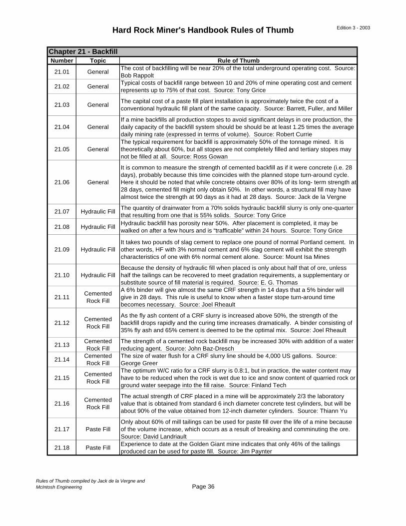
Hard Rock Miner's Handbook Rules of Thumb Edition 3 - 2003
Number Topic Rule of Thumb
21.01 GeneralThe cost of backfilling will be near 20% of the total underground operating cost. Source: Bob Rappolt
21.02 GeneralTypical costs of backfill range between 10 and 20% of mine operating cost and cement represents up to 75% of that cost. Source: Tony Grice
21.03 GeneralThe capital cost of a paste fill plant installation is approximately twice the cost of a conventional hydraulic fill plant of the same capacity. Source: Barrett, Fuller, and Miller
21.04 GeneralIf a mine backfills all production stopes to avoid significant delays in ore production, the daily capacity of the backfill system should be should be at least 1.25 times the average daily mining rate (expressed in terms of volume). Source: Robert Currie
21.05 GeneralThe typical requirement for backfill is approximately 50% of the tonnage mined. It is theoretically about 60%, but all stopes are not completely filled and tertiary stopes may not be filled at all. Source: Ross Gowan
21.06 General
It is common to measure the strength of cemented backfill as if it were concrete (i.e. 28 days), probably because this time coincides with the planned stope turn-around cycle. Here it should be noted that while concrete obtains over 80% of its long- term strength at 28 days, cemented fill might only obtain 50%. In other words, a structural fill may have almost twice the strength at 90 days as it had at 28 days. Source: Jack de la Vergne
21.07 Hydraulic FillThe quantity of drainwater from a 70% solids hydraulic backfill slurry is only one-quarter that resulting from one that is 55% solids. Source: Tony Grice
21.08 Hydraulic FillHydraulic backfill has porosity near 50%. After placement is completed, it may be walked on after a few hours and is “trafficable” within 24 hours. Source: Tony Grice
21.09 Hydraulic FillIt takes two pounds of slag cement to replace one pound of normal Portland cement. In other words, HF with 3% normal cement and 6% slag cement will exhibit the strength characteristics of one with 6% normal cement alone. Source: Mount Isa Mines
21.10 Hydraulic FillBecause the density of hydraulic fill when placed is only about half that of ore, unless half the tailings can be recovered to meet gradation requirements, a supplementary or substitute source of fill material is required. Source: E. G. Thomas
21.11Cemented Rock Fill
A 6% binder will give almost the same CRF strength in 14 days that a 5% binder will give in 28 days. This rule is useful to know when a faster stope turn-around time becomes necessary. Source: Joel Rheault
21.12Cemented Rock Fill
As the fly ash content of a CRF slurry is increased above 50%, the strength of the backfill drops rapidly and the curing time increases dramatically. A binder consisting of 35% fly ash and 65% cement is deemed to be the optimal mix. Source: Joel Rheault
21.13Cemented Rock Fill
The strength of a cemented rock backfill may be increased 30% with addition of a water reducing agent. Source: John Baz-Dresch
21.14Cemented Rock Fill
The size of water flush for a CRF slurry line should be 4,000 US gallons. Source: George Greer
21.15Cemented Rock Fill
The optimum W/C ratio for a CRF slurry is 0.8:1, but in practice, the water content may have to be reduced when the rock is wet due to ice and snow content of quarried rock or ground water seepage into the fill raise. Source: Finland Tech
21.16Cemented Rock Fill
The actual strength of CRF placed in a mine will be approximately 2/3 the laboratory value that is obtained from standard 6 inch diameter concrete test cylinders, but will be about 90% of the value obtained from 12-inch diameter cylinders. Source: Thiann Yu
21.17 Paste FillOnly about 60% of mill tailings can be used for paste fill over the life of a mine because of the volume increase, which occurs as a result of breaking and comminuting the ore. Source: David Landriault
21.18 Paste FillExperience to date at the Golden Giant mine indicates that only 46% of the tailings produced can be used for paste fill. Source: Jim Paynter
Chapter 21 - Backfill
Rules of Thumb compiled by Jack de la Vergne andMcIntosh Engineering Page 36
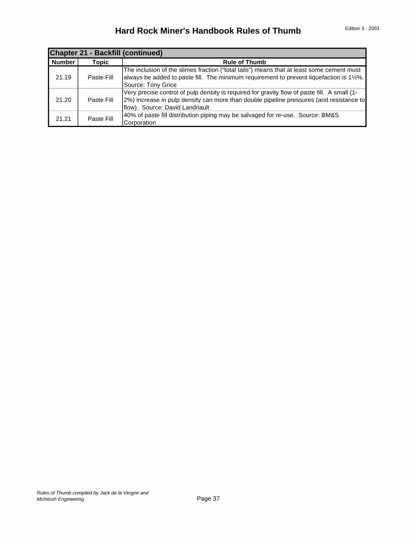
Hard Rock Miner's Handbook Rules of Thumb Edition 3 - 2003
Number Topic Rule of Thumb
21.19 Paste FillThe inclusion of the slimes fraction (“total tails”) means that at least some cement must always be added to paste fill. The minimum requirement to prevent liquefaction is 1½%. Source: Tony Grice
21.20 Paste FillVery precise control of pulp density is required for gravity flow of paste fill. A small (1-2%) increase in pulp density can more than double pipeline pressures (and resistance to flow). Source: David Landriault
21.21 Paste Fill40% of paste fill distribution piping may be salvaged for re-use. Source: BM&S Corporation
Chapter 21 - Backfill (continued)
Rules of Thumb compiled by Jack de la Vergne andMcIntosh Engineering Page 37
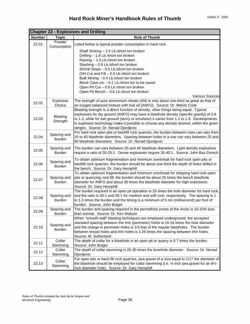
Hard Rock Miner's Handbook Rules of Thumb Edition 3 - 2003
Number Topic Rule of Thumb
22.01Powder
ConsumptionListed below is typical powder consumption in hard rock.
Shaft Sinking – 2.5 Lb./short ton broken Drifting – 1.8 Lb./short ton broken Raising – 1.5 Lb./short ton broken Slashing – 0.8 Lb./short ton broken Shrink Stope – 0.5 Lb./short ton broken O/H Cut and Fill – 0.5 Lb./short ton broken Bulk Mining – 0.4 Lb./short ton broken Block Cave u/c – 0.1 Lb./short ton to be caved Open Pit Cut – 0.9 Lb./short ton broken Open Pit Bench – 0.6 Lb./short ton broken
Various Sources
22.02Explosive
ChoiceThe strength of pure ammonium nitrate (AN) is only about one-third as great as that of an oxygen balanced mixture with fuel oil (ANFO). Source: Dr. Melvin Cook
22.03Blasting Strength
Blasting strength is a direct function of density, other things being equal. Typical explosives for dry ground (ANFO) may have a blasthole density (specific gravity) of 0.8 to 1.3, while for wet ground (slurry or emulsion) it varies from 1.1 to 1.3. Developments in explosive technology make it possible to choose any density desired, within the given ranges. Source: Dr. Nenad Djordjevic
22.04Spacing and
Burden
For hard rock open pits or backfill rock quarries, the burden between rows can vary from 25 to 40 blasthole diameters. Spacing between holes in a row can vary between 25 and 80 blasthole diameters. Source: Dr. Nenad Djordjevic
22.05Spacing and
BurdenThe burden can vary between 20 and 40 blasthole diameters. Light density explosives require a ratio of 20-25:1. Dense explosives require 35-40:1. Source: John Baz-Dresch
22.06Spacing and
Burden
To obtain optimum fragmentation and minimum overbreak for hard rock open pits or backfill rock quarries, the burden should be about one-third the depth of holes drilled in the bench. Source: Dr. Gary Hemphill
22.07Spacing and
Burden
To obtain optimum fragmentation and minimum overbreak for stripping hard rock open pits or quarrying rock fill, the burden should be about 25 times the bench blasthole diameter for ANFO and about 30 times the blasthole diameter for high explosives. Source: Dr. Gary Hemphill
22.08Spacing and
Burden
The burden required in an open pit operation is 25 times the hole diameter for hard rock, and the ratio is 30:1 and 35:1 for medium and soft rock, respectively. The spacing is 1 to 1.5 times the burden and the timing is a minimum of 5 ms (millisecond) per foot of burden. Source: John Bolger
22.09Spacing and
BurdenThe burden and spacing required in the permafrost zones of the Arctic is 10-15% less than normal. Source: Dr. Ken Watson
22.10Spacing and
Burden
When “smooth wall” blasting techniques are employed underground, the accepted standard spacing between the trim (perimeter) holes is 15-16 times the hole diameter and the charge in perimeter holes is 1/3 that of the regular blastholes. The burden between breast holes and trim holes is 1.25 times the spacing between trim holes. Source: M. Sutherland
22.11Collar
StemmingThe depth of collar for a blasthole in an open pit or quarry is 0.7 times the burden. Source: John Bolger
22.12Collar
StemmingThe depth of collar stemming is 20-30 times the borehole diameter. Source: Dr. Nenad Djordjevic
22.13Collar
Stemming
For open pits or back-fill rock quarries, pea gravel of a size equal to 1/17 the diameter of the blasthole should be employed for collar stemming (i.e. ½ inch pea gravel for an 8½-inch diameter hole). Source: Dr. Gary Hemphill
Chapter 22 - Explosives and Drilling
Rules of Thumb compiled by Jack de la Vergne andMcIntosh Engineering Page 38
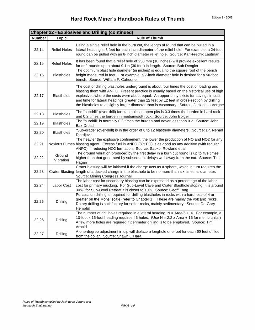
Hard Rock Miner's Handbook Rules of Thumb Edition 3 - 2003
Number Topic Rule of Thumb
22.14 Relief HolesUsing a single relief hole in the burn cut, the length of round that can be pulled in a lateral heading is 3 feet for each inch diameter of the relief hole. For example, a 24-foot round can be pulled with an 8-inch diameter relief hole. Source: Karl-Fredrik Lautman
22.15 Relief HolesIt has been found that a relief hole of 250 mm (10 inches) will provide excellent results for drift rounds up to about 9.1m (30 feet) in length. Source: Bob Dengler
22.16 BlastholesThe optimium blast hole diameter (in inches) is equal to the square root of the bench height measured in feet. For example, a 7-inch diameter hole is desired for a 50-foot bench. Source: William F. Cahoone
22.17 Blastholes
The cost of drilling blastholes underground is about four times the cost of loading and blasting them with ANFO. Present practice is usually based on the historical use of high explosives where the costs were about equal. An opportunity exists for savings in cost and time for lateral headings greater than 12 feet by 12 feet in cross-section by drilling the blastholes to a slightly larger diameter than is customary. Source: Jack de la Vergne
22.18 BlastholesThe “subdrill” (over-drill) for blastholes in open pits is 0.3 times the burden in hard rock and 0.2 times the burden in medium/soft rock. Source: John Bolger
22.19 BlastholesThe "subdrill" is normally 0.3 times the burden and never less than 0.2. Source: John Baz-Dresch
22.20 Blastholes“Sub-grade” (over-drill) is in the order of 8 to 12 blasthole diameters. Source: Dr. Nenad Djordjevic
22.21 Noxious FumesThe heavier the explosive confinement, the lower the production of NO and NO2 for any blasting agent. Excess fuel in ANFO (8% FO) is as good as any additive (with regular ANFO) in reducing NO2 formation. Source: Sapko, Rowland et al
22.22Ground
Vibration
The ground vibration produced by the first delay in a burn cut round is up to five times higher than that generated by subsequent delays well away from the cut. Source: Tim Hagan
22.23 Crater BlastingCrater blasting will be initiated if the charge acts as a sphere, which in turn requires the length of a decked charge in the blasthole to be no more than six times its diameter. Source: Mining Congress Journal
22.24 Labor CostThe labor cost for secondary blasting can be expressed as a percentage of the labor cost for primary mucking. For Sub-Level Cave and Crater Blasthole stoping, it is around 30%; for Sub-Level Retreat it is closer to 10%. Source: Geoff Fong
22.25 Drilling
Percussion drilling is required for drilling blastholes in rocks with a hardness of 4 or greater on the Mohs’ scale (refer to Chapter 1). These are mainly the volcanic rocks. Rotary drilling is satisfactory for softer rocks, mainly sedimentary. Source: Dr. Gary Hemphill
22.26 Drilling
The number of drill holes required in a lateral heading, N = Area/5 +16. For example, a 10-foot x 15-foot heading requires 46 holes. (Use N = 2.2 x Area + 16 for metric units.) A few more holes are required if perimeter drilling is to be employed. Source: Tim Arnold
22.27 DrillingA one-degree adjustment in dip will diplace a longhole one foot for each 60 feet drilled from the collar. Source: Shawn O'Hara
Chapter 22 - Explosives and Drilling (continued)
Rules of Thumb compiled by Jack de la Vergne andMcIntosh Engineering Page 39
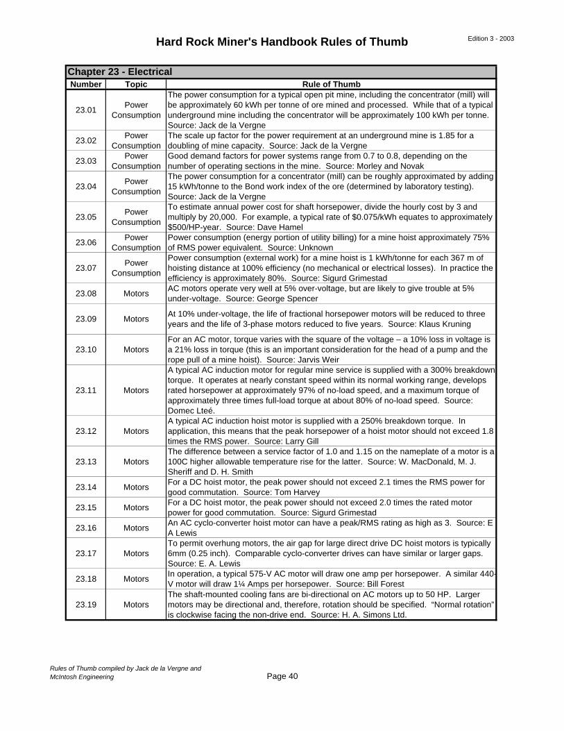
Hard Rock Miner's Handbook Rules of Thumb Edition 3 - 2003
Number Topic Rule of Thumb
23.01Power
Consumption
The power consumption for a typical open pit mine, including the concentrator (mill) will be approximately 60 kWh per tonne of ore mined and processed. While that of a typical underground mine including the concentrator will be approximately 100 kWh per tonne. Source: Jack de la Vergne
23.02Power
ConsumptionThe scale up factor for the power requirement at an underground mine is 1.85 for a doubling of mine capacity. Source: Jack de la Vergne
23.03Power
ConsumptionGood demand factors for power systems range from 0.7 to 0.8, depending on the number of operating sections in the mine. Source: Morley and Novak
23.04Power
Consumption
The power consumption for a concentrator (mill) can be roughly approximated by adding 15 kWh/tonne to the Bond work index of the ore (determined by laboratory testing). Source: Jack de la Vergne
23.05Power
Consumption
To estimate annual power cost for shaft horsepower, divide the hourly cost by 3 and multiply by 20,000. For example, a typical rate of $0.075/kWh equates to approximately $500/HP-year. Source: Dave Hamel
23.06Power
ConsumptionPower consumption (energy portion of utility billing) for a mine hoist approximately 75% of RMS power equivalent. Source: Unknown
23.07Power
Consumption
Power consumption (external work) for a mine hoist is 1 kWh/tonne for each 367 m of hoisting distance at 100% efficiency (no mechanical or electrical losses). In practice the efficiency is approximately 80%. Source: Sigurd Grimestad
23.08 MotorsAC motors operate very well at 5% over-voltage, but are likely to give trouble at 5% under-voltage. Source: George Spencer
23.09 MotorsAt 10% under-voltage, the life of fractional horsepower motors will be reduced to three years and the life of 3-phase motors reduced to five years. Source: Klaus Kruning
23.10 MotorsFor an AC motor, torque varies with the square of the voltage – a 10% loss in voltage is a 21% loss in torque (this is an important consideration for the head of a pump and the rope pull of a mine hoist). Source: Jarvis Weir
23.11 Motors
A typical AC induction motor for regular mine service is supplied with a 300% breakdown torque. It operates at nearly constant speed within its normal working range, develops rated horsepower at approximately 97% of no-load speed, and a maximum torque of approximately three times full-load torque at about 80% of no-load speed. Source: Domec Lteé.
23.12 MotorsA typical AC induction hoist motor is supplied with a 250% breakdown torque. In application, this means that the peak horsepower of a hoist motor should not exceed 1.8 times the RMS power. Source: Larry Gill
23.13 MotorsThe difference between a service factor of 1.0 and 1.15 on the nameplate of a motor is a 100C higher allowable temperature rise for the latter. Source: W. MacDonald, M. J. Sheriff and D. H. Smith
23.14 MotorsFor a DC hoist motor, the peak power should not exceed 2.1 times the RMS power for good commutation. Source: Tom Harvey
23.15 MotorsFor a DC hoist motor, the peak power should not exceed 2.0 times the rated motor power for good commutation. Source: Sigurd Grimestad
23.16 MotorsAn AC cyclo-converter hoist motor can have a peak/RMS rating as high as 3. Source: E A Lewis
23.17 MotorsTo permit overhung motors, the air gap for large direct drive DC hoist motors is typically 6mm (0.25 inch). Comparable cyclo-converter drives can have similar or larger gaps. Source: E. A. Lewis
23.18 MotorsIn operation, a typical 575-V AC motor will draw one amp per horsepower. A similar 440-V motor will draw 1¼ Amps per horsepower. Source: Bill Forest
23.19 MotorsThe shaft-mounted cooling fans are bi-directional on AC motors up to 50 HP. Larger motors may be directional and, therefore, rotation should be specified. “Normal rotation” is clockwise facing the non-drive end. Source: H. A. Simons Ltd.
Chapter 23 - Electrical
Rules of Thumb compiled by Jack de la Vergne andMcIntosh Engineering Page 40
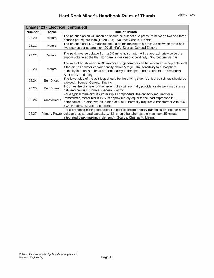
Hard Rock Miner's Handbook Rules of Thumb Edition 3 - 2003
Number Topic Rule of Thumb
23.20 MotorsThe brushes on an AC machine should be first set at a pressure between two and three pounds per square inch (15-20 kPa). Source: General Electric
23.21 MotorsThe brushes on a DC machine should be maintained at a pressure between three and five pounds per square inch (20-35 kPa). Source: General Electric
23.22 MotorsThe peak inverse voltage from a DC mine hoist motor will be approximately twice the supply voltage so the thyristor bank is designed accordingly. Source: Jim Bernas
23.23 Motors
The rate of brush wear on DC motors and generators can be kept to an acceptable level if the air has a water vapour density above 5 mg/l. The sensitivity to atmosphere humidity increases at least proportionately to the speed (of rotation of the armature). Source: Gerald Tiley
23.24 Belt DrivesThe lower side of the belt loop should be the driving side. Vertical belt drives should be avoided. Source: General Electric
23.25 Belt Drives2½ times the diameter of the larger pulley will normally provide a safe working distance between centers. Source: General Electric
23.26 Transformers
For a typical mine circuit with multiple components, the capacity required for a transformer, measured in kVA, is approximately equal to the load expressed in horsepower. In other words, a load of 500HP normally requires a transformer with 500-kVA capacity. Source: Bill Forest
23.27 Primary PowerFor a proposed mining operation it is best to design primary transmission lines for a 5% voltage drop at rated capacity, which should be taken as the maximum 15-minute integrated peak (maximum demand). Source: Charles M. Means
Chapter 23 - Electrical (continued)
Rules of Thumb compiled by Jack de la Vergne andMcIntosh Engineering Page 41
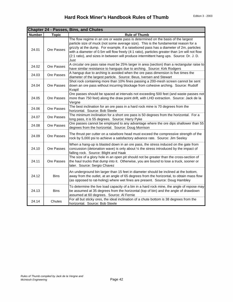
Hard Rock Miner's Handbook Rules of Thumb Edition 3 - 2003
Number Topic Rule of Thumb
24.01 Ore Passes
The flow regime in an ore or waste pass is determined on the basis of the largest particle size of muck (not some average size). This is the fundamental reason for a grizzly at the dump. For example, if a raisebored pass has a diameter of 2m, particles with a diameter of 0.5m will flow freely (4:1 ratio), particles greater than 1m will not flow (2:1 ratio), and sizes in between will produce intermittent hang ups. Source: Dr. J. D. Just
24.02 Ore PassesA circular ore pass raise must be 25% larger in area (section) than a rectangular raise to have similar resistance to hangups due to arching. Source: Kirk Rodgers
24.03 Ore PassesA hangup due to arching is avoided when the ore pass dimension is five times the diameter of the largest particle. Source: Beus, Iversen and Stewart
24.04 Ore PassesShot rock containing more than 10% fines passing a 200-mesh screen cannot be sent down an ore pass without incurring blockage from cohesive arching. Source: Rudolf Kvapil
24.05 Ore PassesOre passes should be spaced at intervals not exceeding 500 feet (and waste passes not more than 750 feet) along the draw point drift, with LHD extraction. Source: Jack de la Vergne
24.06 Ore PassesThe best inclination for an ore pass in a hard rock mine is 70 degrees from the horizontal. Source: Bob Steele
24.07 Ore PassesThe minimum inclination for a short ore pass is 50 degrees from the horizontal. For a long pass, it is 55 degrees. Source: Harry Pyke
24.08 Ore PassesOre passes cannot be employed to any advantage where the ore dips shallower than 55 degrees from the horizontal. Source: Doug Morrison
24.09 Ore PassesThe thrust per cutter on a raisebore head must exceed the compressive strength of the rock by 5,000 psi to achieve a satisfactory advance rate. Source: Jim Seeley
24.10 Ore PassesWhen a hang-up is blasted down in an ore pass, the stress induced on the gate from concussion (detonation wave) is only about ¼ the stress introduced by the impact of falling rock. Source: Blight and Haak
24.11 Ore PassesThe size of a glory hole in an open pit should not be greater than the cross-section of the haul trucks that dump into it. Otherwise, you are bound to lose a truck, sooner or later. Source: Sergio Chavez
24.12 BinsAn underground bin larger than 15 feet in diameter should be inclined at the bottom, away from the outlet, at an angle of 65 degrees from the horizontal, to obtain mass flow (as opposed to rat-holing) where wet fines are present. Source: Doug Hambley
24.13 BinsTo determine the live load capacity of a bin in a hard rock mine, the angle of repose may be assumed at 35 degrees from the horizontal (top of bin) and the angle of drawdown assumed at 60 degrees. Source: Al Fernie
24.14 ChutesFor all but sticky ores, the ideal inclination of a chute bottom is 38 degrees from the horizontal. Source: Bob Steele
Chapter 24 - Passes, Bins, and Chutes
Rules of Thumb compiled by Jack de la Vergne andMcIntosh Engineering Page 42
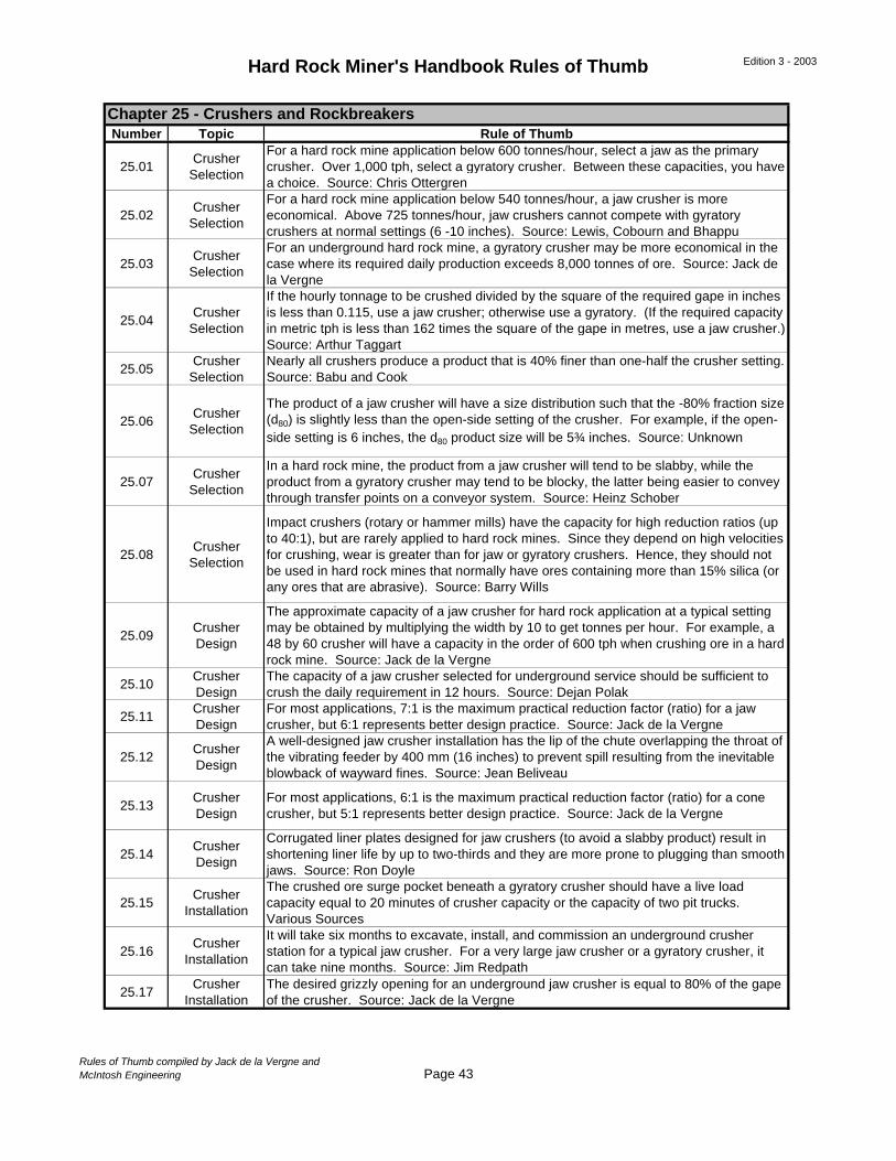
Hard Rock Miner's Handbook Rules of Thumb Edition 3 - 2003
Number Topic Rule of Thumb
25.01Crusher
Selection
For a hard rock mine application below 600 tonnes/hour, select a jaw as the primary crusher. Over 1,000 tph, select a gyratory crusher. Between these capacities, you have a choice. Source: Chris Ottergren
25.02Crusher
Selection
For a hard rock mine application below 540 tonnes/hour, a jaw crusher is more economical. Above 725 tonnes/hour, jaw crushers cannot compete with gyratory crushers at normal settings (6 -10 inches). Source: Lewis, Cobourn and Bhappu
25.03Crusher
Selection
For an underground hard rock mine, a gyratory crusher may be more economical in the case where its required daily production exceeds 8,000 tonnes of ore. Source: Jack de la Vergne
25.04Crusher
Selection
If the hourly tonnage to be crushed divided by the square of the required gape in inches is less than 0.115, use a jaw crusher; otherwise use a gyratory. (If the required capacity in metric tph is less than 162 times the square of the gape in metres, use a jaw crusher.) Source: Arthur Taggart
25.05Crusher
SelectionNearly all crushers produce a product that is 40% finer than one-half the crusher setting. Source: Babu and Cook
25.06Crusher
Selection
The product of a jaw crusher will have a size distribution such that the -80% fraction size (d80) is slightly less than the open-side setting of the crusher. For example, if the open-side setting is 6 inches, the d80 product size will be 5¾ inches. Source: Unknown
25.07Crusher
Selection
In a hard rock mine, the product from a jaw crusher will tend to be slabby, while the product from a gyratory crusher may tend to be blocky, the latter being easier to convey through transfer points on a conveyor system. Source: Heinz Schober
25.08Crusher
Selection
Impact crushers (rotary or hammer mills) have the capacity for high reduction ratios (up to 40:1), but are rarely applied to hard rock mines. Since they depend on high velocities for crushing, wear is greater than for jaw or gyratory crushers. Hence, they should not be used in hard rock mines that normally have ores containing more than 15% silica (or any ores that are abrasive). Source: Barry Wills
25.09Crusher Design
The approximate capacity of a jaw crusher for hard rock application at a typical setting may be obtained by multiplying the width by 10 to get tonnes per hour. For example, a 48 by 60 crusher will have a capacity in the order of 600 tph when crushing ore in a hard rock mine. Source: Jack de la Vergne
25.10Crusher Design
The capacity of a jaw crusher selected for underground service should be sufficient to crush the daily requirement in 12 hours. Source: Dejan Polak
25.11Crusher Design
For most applications, 7:1 is the maximum practical reduction factor (ratio) for a jaw crusher, but 6:1 represents better design practice. Source: Jack de la Vergne
25.12Crusher Design
A well-designed jaw crusher installation has the lip of the chute overlapping the throat of the vibrating feeder by 400 mm (16 inches) to prevent spill resulting from the inevitable blowback of wayward fines. Source: Jean Beliveau
25.13Crusher Design
For most applications, 6:1 is the maximum practical reduction factor (ratio) for a cone crusher, but 5:1 represents better design practice. Source: Jack de la Vergne
25.14Crusher Design
Corrugated liner plates designed for jaw crushers (to avoid a slabby product) result in shortening liner life by up to two-thirds and they are more prone to plugging than smooth jaws. Source: Ron Doyle
25.15Crusher
Installation
The crushed ore surge pocket beneath a gyratory crusher should have a live load capacity equal to 20 minutes of crusher capacity or the capacity of two pit trucks. Various Sources
25.16Crusher
Installation
It will take six months to excavate, install, and commission an underground crusher station for a typical jaw crusher. For a very large jaw crusher or a gyratory crusher, it can take nine months. Source: Jim Redpath
25.17Crusher
InstallationThe desired grizzly opening for an underground jaw crusher is equal to 80% of the gape of the crusher. Source: Jack de la Vergne
Chapter 25 - Crushers and Rockbreakers
Rules of Thumb compiled by Jack de la Vergne andMcIntosh Engineering Page 43
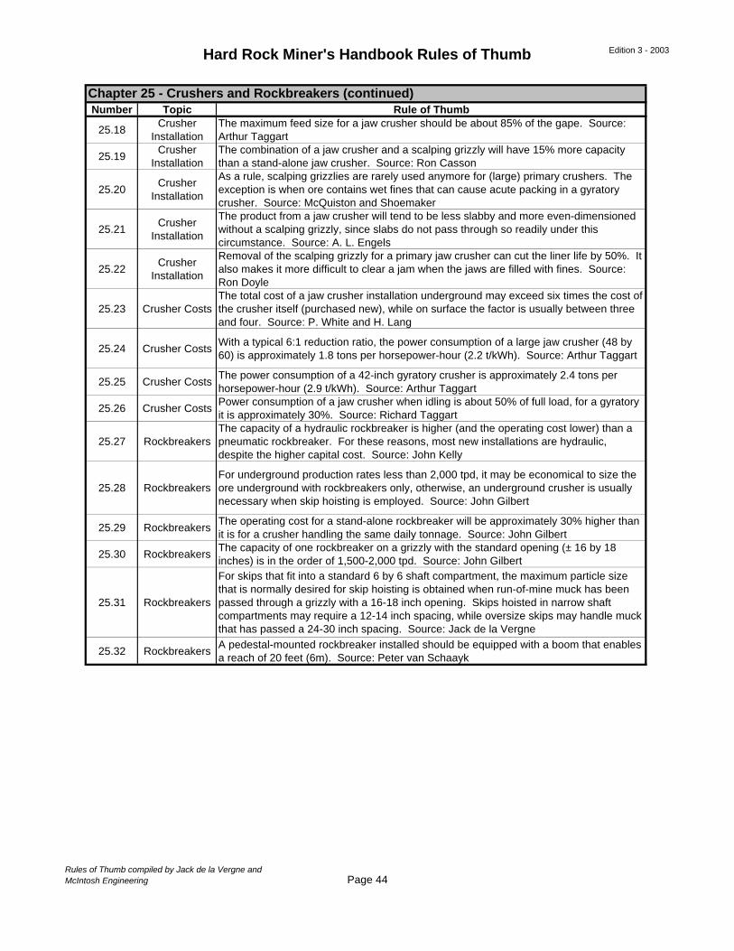
Hard Rock Miner's Handbook Rules of Thumb Edition 3 - 2003
Number Topic Rule of Thumb
25.18Crusher
InstallationThe maximum feed size for a jaw crusher should be about 85% of the gape. Source: Arthur Taggart
25.19Crusher
InstallationThe combination of a jaw crusher and a scalping grizzly will have 15% more capacity than a stand-alone jaw crusher. Source: Ron Casson
25.20Crusher
Installation
As a rule, scalping grizzlies are rarely used anymore for (large) primary crushers. The exception is when ore contains wet fines that can cause acute packing in a gyratory crusher. Source: McQuiston and Shoemaker
25.21Crusher
Installation
The product from a jaw crusher will tend to be less slabby and more even-dimensioned without a scalping grizzly, since slabs do not pass through so readily under this circumstance. Source: A. L. Engels
25.22Crusher
Installation
Removal of the scalping grizzly for a primary jaw crusher can cut the liner life by 50%. It also makes it more difficult to clear a jam when the jaws are filled with fines. Source: Ron Doyle
25.23 Crusher CostsThe total cost of a jaw crusher installation underground may exceed six times the cost of the crusher itself (purchased new), while on surface the factor is usually between three and four. Source: P. White and H. Lang
25.24 Crusher CostsWith a typical 6:1 reduction ratio, the power consumption of a large jaw crusher (48 by 60) is approximately 1.8 tons per horsepower-hour (2.2 t/kWh). Source: Arthur Taggart
25.25 Crusher CostsThe power consumption of a 42-inch gyratory crusher is approximately 2.4 tons per horsepower-hour (2.9 t/kWh). Source: Arthur Taggart
25.26 Crusher CostsPower consumption of a jaw crusher when idling is about 50% of full load, for a gyratory it is approximately 30%. Source: Richard Taggart
25.27 RockbreakersThe capacity of a hydraulic rockbreaker is higher (and the operating cost lower) than a pneumatic rockbreaker. For these reasons, most new installations are hydraulic, despite the higher capital cost. Source: John Kelly
25.28 RockbreakersFor underground production rates less than 2,000 tpd, it may be economical to size the ore underground with rockbreakers only, otherwise, an underground crusher is usually necessary when skip hoisting is employed. Source: John Gilbert
25.29 RockbreakersThe operating cost for a stand-alone rockbreaker will be approximately 30% higher than it is for a crusher handling the same daily tonnage. Source: John Gilbert
25.30 RockbreakersThe capacity of one rockbreaker on a grizzly with the standard opening (± 16 by 18 inches) is in the order of 1,500-2,000 tpd. Source: John Gilbert
25.31 Rockbreakers
For skips that fit into a standard 6 by 6 shaft compartment, the maximum particle size that is normally desired for skip hoisting is obtained when run-of-mine muck has been passed through a grizzly with a 16-18 inch opening. Skips hoisted in narrow shaft compartments may require a 12-14 inch spacing, while oversize skips may handle muck that has passed a 24-30 inch spacing. Source: Jack de la Vergne
25.32 RockbreakersA pedestal-mounted rockbreaker installed should be equipped with a boom that enables a reach of 20 feet (6m). Source: Peter van Schaayk
Chapter 25 - Crushers and Rockbreakers (continued)
Rules of Thumb compiled by Jack de la Vergne andMcIntosh Engineering Page 44
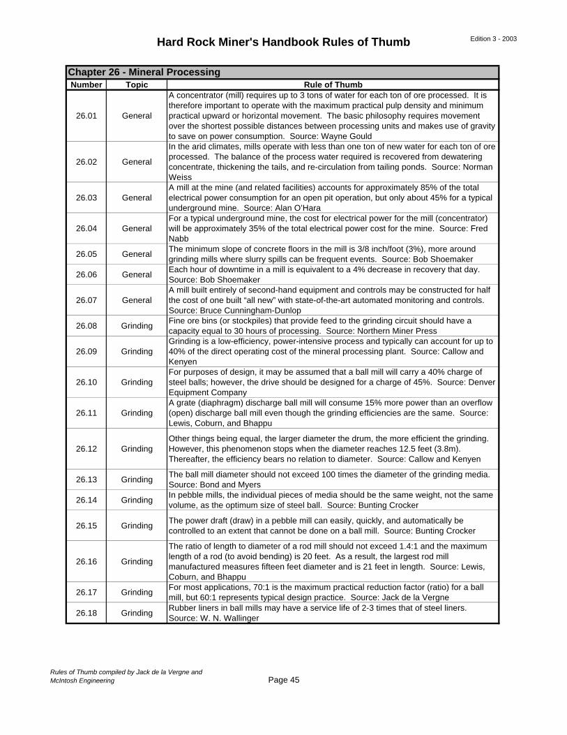
Hard Rock Miner's Handbook Rules of Thumb Edition 3 - 2003
Number Topic Rule of Thumb
26.01 General
A concentrator (mill) requires up to 3 tons of water for each ton of ore processed. It is therefore important to operate with the maximum practical pulp density and minimum practical upward or horizontal movement. The basic philosophy requires movement over the shortest possible distances between processing units and makes use of gravity to save on power consumption. Source: Wayne Gould
26.02 General
In the arid climates, mills operate with less than one ton of new water for each ton of ore processed. The balance of the process water required is recovered from dewatering concentrate, thickening the tails, and re-circulation from tailing ponds. Source: Norman Weiss
26.03 GeneralA mill at the mine (and related facilities) accounts for approximately 85% of the total electrical power consumption for an open pit operation, but only about 45% for a typical underground mine. Source: Alan O’Hara
26.04 GeneralFor a typical underground mine, the cost for electrical power for the mill (concentrator) will be approximately 35% of the total electrical power cost for the mine. Source: Fred Nabb
26.05 GeneralThe minimum slope of concrete floors in the mill is 3/8 inch/foot (3%), more around grinding mills where slurry spills can be frequent events. Source: Bob Shoemaker
26.06 GeneralEach hour of downtime in a mill is equivalent to a 4% decrease in recovery that day. Source: Bob Shoemaker
26.07 GeneralA mill built entirely of second-hand equipment and controls may be constructed for half the cost of one built “all new” with state-of-the-art automated monitoring and controls. Source: Bruce Cunningham-Dunlop
26.08 GrindingFine ore bins (or stockpiles) that provide feed to the grinding circuit should have a capacity equal to 30 hours of processing. Source: Northern Miner Press
26.09 GrindingGrinding is a low-efficiency, power-intensive process and typically can account for up to 40% of the direct operating cost of the mineral processing plant. Source: Callow and Kenyen
26.10 GrindingFor purposes of design, it may be assumed that a ball mill will carry a 40% charge of steel balls; however, the drive should be designed for a charge of 45%. Source: Denver Equipment Company
26.11 GrindingA grate (diaphragm) discharge ball mill will consume 15% more power than an overflow (open) discharge ball mill even though the grinding efficiencies are the same. Source: Lewis, Coburn, and Bhappu
26.12 GrindingOther things being equal, the larger diameter the drum, the more efficient the grinding. However, this phenomenon stops when the diameter reaches 12.5 feet (3.8m). Thereafter, the efficiency bears no relation to diameter. Source: Callow and Kenyen
26.13 GrindingThe ball mill diameter should not exceed 100 times the diameter of the grinding media. Source: Bond and Myers
26.14 GrindingIn pebble mills, the individual pieces of media should be the same weight, not the same volume, as the optimum size of steel ball. Source: Bunting Crocker
26.15 GrindingThe power draft (draw) in a pebble mill can easily, quickly, and automatically be controlled to an extent that cannot be done on a ball mill. Source: Bunting Crocker
26.16 Grinding
The ratio of length to diameter of a rod mill should not exceed 1.4:1 and the maximum length of a rod (to avoid bending) is 20 feet. As a result, the largest rod mill manufactured measures fifteen feet diameter and is 21 feet in length. Source: Lewis, Coburn, and Bhappu
26.17 GrindingFor most applications, 70:1 is the maximum practical reduction factor (ratio) for a ball mill, but 60:1 represents typical design practice. Source: Jack de la Vergne
26.18 GrindingRubber liners in ball mills may have a service life of 2-3 times that of steel liners. Source: W. N. Wallinger
Chapter 26 - Mineral Processing
Rules of Thumb compiled by Jack de la Vergne andMcIntosh Engineering Page 45

Hard Rock Miner's Handbook Rules of Thumb Edition 3 - 2003
Number Topic Rule of Thumb
26.19 GrindingThe capacity of a mill with synthetic rubber liners is approximately 90% that of the same unit with steel liners. Source: Yanko Tirado
26.20 GrindingThe capacity of a grinding mill for a given product operating in open circuit is only 80% that of the same unit operating in closed circuit. Source: Lewis, Coburn and Bhappu
26.21 GrindingA dual drive (i.e. twin motors and pinions driving a single ring gear) may be more economical than a single drive when the grinding mill is designed to draw more than 6,000 HP (4.5 Mw). Source: Rowland and Kjos
26.22 Grinding Geared drives are currently available up to 9,500HP. Source: Barrat and Pfiefer
26.23 GrindingA direct drive ring motor (gearless drive) is the only option for an autogenous mill rated over 20,000 HP. Source: Mac Brodie
26.24 ClassifiersThe ratio of diameters between the vortex finder (overflow exit) and the apex (underflow exit) of a hydrocyclone classifier must be kept greater than 2:1, otherwise operation may be unpredictable. Source: Chuck Lagergren and Gary Lubers
26.25Gravity
Separation
For gravity separation to be possible, the ratio of the difference in density of the heavy mineral and the medium and the difference between the light mineral and the medium must be greater than 1.25. Source: Arthur Taggart
26.26Gravity
Separation
Most all wet gravity separation equipment is sensitive to the presence of slimes (minus 400 mesh). Slimes in excess of 5% should be avoided. More than 10% causes serious separation problems. Source: Chris Mills
26.27 LeachingThe actual cyanide consumption at a heap leach operation will be no more than one-third the rate indicated by column leach tests. Source: Tim Arnold
26.28 FlotationClean metallic gold particles (free gold) finer than 200 microns (65 mesh) float readily with appropriate reagents. Gravity separation is desirable for larger particles. Source: Mining Chemicals Handbook (Cyanamid)
26.29 FlotationWhen designing the flotation circuit for a proposed mill, the scale-up factor for flotation retention times obtained from bench tests is approximately two. Source: Mining Chemicals Handbook (Cyanamid)
26.30 FlotationTo determine a preliminary water balance for a proposed flotation circuit, the pulp density may be assumed to be 30% solids (by weight). Source: Rex Bull
26.31 FlotationAs a rule, water-soluble collectors may be added anywhere in the circuit, but oily, insoluble promoters should always be added to the grinding mill. Source: Keith Suttill
26.32 FlotationFor roasting to be exothermic to the extent that no fuel is required to sustain reaction, the flotation product must contain at least 17% sulfur. Therefore, the target is 18%. Source: Dickson and Reid
26.33 FiltrationWhen designing the filters required for a proposed mill, the scale-up factor from bench tests is approximately 0.8. Source: Donald Dahlstrom
26.34 FiltrationWhen determining vacuum pumps for filter installations required for a proposed mill, the scale-up factor from bench tests is approximately 1.1. Source: Donald Dahlstrom
26.35 ConcentrateThe typical moisture content of concentrates shipped from the mine is often near 5%. If the moisture content is less than 4%, the potential for dust losses becomes significant. Source: Ken Kolthammer
26.36 ConcentrateThe moisture content of concentrate measured by a custom smelter will invariably be 1% higher than was correctly measured by the mine when it was shipped. Source: Edouardo Escala
Chapter 26 - Mineral Processing (continued)
Rules of Thumb compiled by Jack de la Vergne andMcIntosh Engineering Page 46
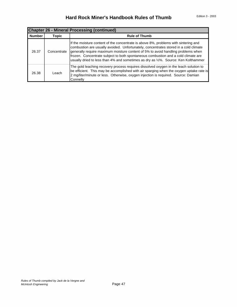
Hard Rock Miner's Handbook Rules of Thumb Edition 3 - 2003
Number Topic Rule of Thumb
26.37 Concentrate
If the moisture content of the concentrate is above 8%, problems with sintering and combustion are usually avoided. Unfortunately, concentrates stored in a cold climate generally require maximum moisture content of 5% to avoid handling problems when frozen. Concentrate subject to both spontaneous combustion and a cold climate are usually dried to less than 4% and sometimes as dry as ½%. Source: Ken Kolthammer
26.38 Leach
The gold leaching recovery process requires dissolved oxygen in the leach solution to be efficient. This may be accomplished with air sparging when the oxygen uptake rate is 2 mg/liter/minute or less. Otherwise, oxygen injection is required. Source: Damian Connelly
Chapter 26 - Mineral Processing (continued)
Rules of Thumb compiled by Jack de la Vergne andMcIntosh Engineering Page 47
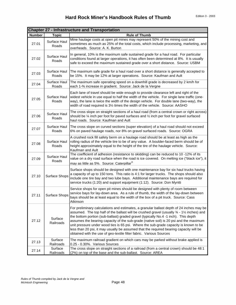
Hard Rock Miner's Handbook Rules of Thumb Edition 3 - 2003
Number Topic Rule of Thumb
27.01Surface Haul
Roads
Mine haulage costs at open pit mines may represent 50% of the mining cost and sometimes as much as 25% of the total costs, which include processing, marketing, and overheads. Source: A. K. Burton
27.02Surface Haul
Roads
In general, 10% is the maximum safe sustained grade for a haul road. For particular conditions found at larger operations, it has often been determined at 8%. It is usually safe to exceed the maximum sustained grade over a short distance. Source: USBM
27.03Surface Haul
RoadsThe maximum safe grade for a haul road over a short distance is generally accepted to be 15%. It may be 12% at larger operations. Source: Kaufman and Ault
27.04Surface Haul
RoadsThe maximum safe operating speed on a downhill grade is decreased by 2 km/h for each 1-% increase in gradient. Source: Jack de la Vergne
27.05Surface Haul
Roads
Each lane of travel should be wide enough to provide clearance left and right of the widest vehicle in use equal to half the width of the vehicle. For single lane traffic (one-way), the lane is twice the width of the design vehicle. For double lane (two-way), the width of road required is 3½ times the width of the vehicle. Source: AASHO
27.06Surface Haul
Roads
The cross slope on straight sections of a haul road (from a central crown or right across) should be ¼ inch per foot for paved surfaces and ½ inch per foot for gravel surfaced haul roads. Source: Kaufman and Ault
27.07Surface Haul
RoadsThe cross slope on curved sections (super elevation) of a haul road should not exceed 6% on paved haulage roads, nor 8% on gravel surfaced roads. Source: OGRA
27.08Surface Haul
Roads
A crushed rock fill safety berm on a haulage road should be at least as high as the rolling radius of the vehicle tire to be of any value. A boulder-faced berm should be of height approximately equal to the height of the tire of the haulage vehicle. Source: Kaufman and Ault
27.09Surface Haul
Roads
The coefficient of adhesion (resistance to skidding) can be reduced to 10 -12% of its value on a dry road surface when the road is ice covered. On melting ice (“black ice”), it may as little as 5%. Source: Caterpillar®
27.10 Surface Shops
Surface shops should be designed with one maintenance bay for six haul trucks having a capacity of up to 150 tons. This ratio is 4:1 for larger trucks. The shops should also include one tire bay and two lube bays. Additional maintenance bays are required for service trucks (1:20) and support equipment (1:12). Source: Don Myntti
27.11 Surface Shops
Service shops for open pit mines should be designed with plenty of room between service bays for lay-down area. As a rule of thumb, the width of the lay-down between bays should be at least equal to the width of the box of a pit truck. Source: Cass Atkinson
27.12Surface
Railroads
For preliminary calculations and estimates, a granular ballast depth of 24 inches may be assumed. The top half of the ballast will be crushed gravel (usually ¾ - 1½ inches) and the bottom portion (sub-ballast) graded gravel (typically No.4 -1 inch). This depth assumes the bearing capacity of the sub-grade (native soil) is 20 psi and the maximum unit pressure under wood ties is 65 psi. Where the sub-grade capacity is known to be less than 20 psi, it may usually be assumed that the required bearing capacity will be obtained with the use of geo-textile filter fabric. Various Sources
27.13Surface
RailroadsThe maximum railroad gradient on which cars may be parked without brake applied is 0.25 - 0.30%. Various Sources
27.14Surface
RailroadsThe cross slope on straight sections of a railroad (from a central crown) should be 48:1 (2%) on top of the base and the sub-ballast. Source: AREA
Chapter 27 - Infrastructure and Transportation
Rules of Thumb compiled by Jack de la Vergne andMcIntosh Engineering Page 48
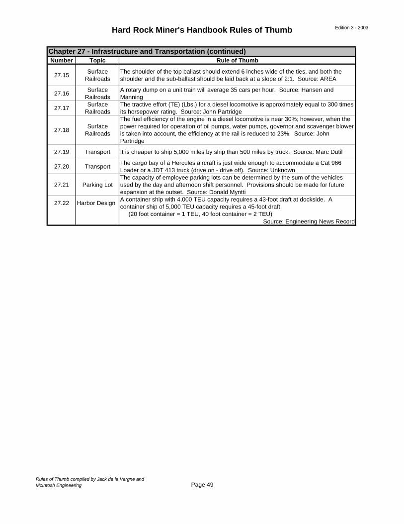
Hard Rock Miner's Handbook Rules of Thumb Edition 3 - 2003
Number Topic Rule of Thumb
27.15Surface
RailroadsThe shoulder of the top ballast should extend 6 inches wide of the ties, and both the shoulder and the sub-ballast should be laid back at a slope of 2:1. Source: AREA
27.16Surface
RailroadsA rotary dump on a unit train will average 35 cars per hour. Source: Hansen and Manning
27.17Surface
RailroadsThe tractive effort (TE) (Lbs.) for a diesel locomotive is approximately equal to 300 times its horsepower rating. Source: John Partridge
27.18Surface
Railroads
The fuel efficiency of the engine in a diesel locomotive is near 30%; however, when the power required for operation of oil pumps, water pumps, governor and scavenger blower is taken into account, the efficiency at the rail is reduced to 23%. Source: John Partridge
27.19 Transport It is cheaper to ship 5,000 miles by ship than 500 miles by truck. Source: Marc Dutil
27.20 TransportThe cargo bay of a Hercules aircraft is just wide enough to accommodate a Cat 966 Loader or a JDT 413 truck (drive on - drive off). Source: Unknown
27.21 Parking LotThe capacity of employee parking lots can be determined by the sum of the vehicles used by the day and afternoon shift personnel. Provisions should be made for future expansion at the outset. Source: Donald Myntti
27.22 Harbor DesignA container ship with 4,000 TEU capacity requires a 43-foot draft at dockside. A container ship of 5,000 TEU capacity requires a 45-foot draft. (20 foot container = 1 TEU, 40 foot container = 2 TEU)
Source: Engineering News Record
Chapter 27 - Infrastructure and Transportation (continued)
Rules of Thumb compiled by Jack de la Vergne andMcIntosh Engineering Page 49
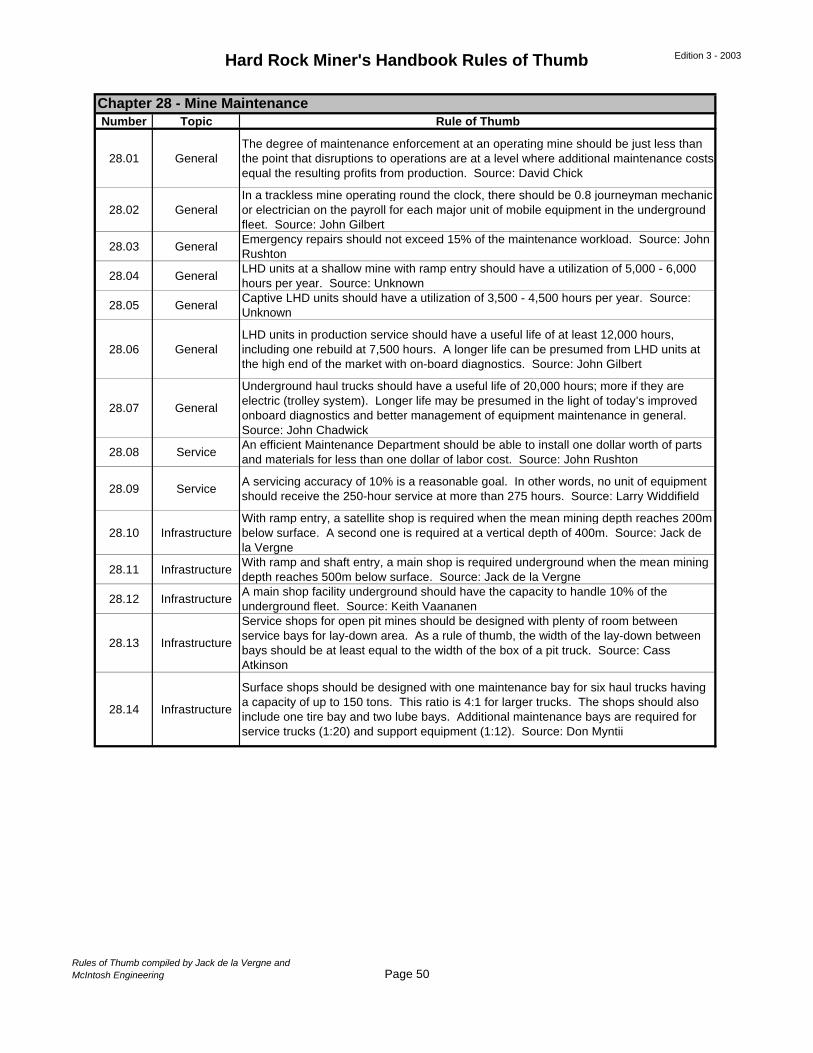
Hard Rock Miner's Handbook Rules of Thumb Edition 3 - 2003
Number Topic Rule of Thumb
28.01 GeneralThe degree of maintenance enforcement at an operating mine should be just less than the point that disruptions to operations are at a level where additional maintenance costs equal the resulting profits from production. Source: David Chick
28.02 GeneralIn a trackless mine operating round the clock, there should be 0.8 journeyman mechanic or electrician on the payroll for each major unit of mobile equipment in the underground fleet. Source: John Gilbert
28.03 GeneralEmergency repairs should not exceed 15% of the maintenance workload. Source: John Rushton
28.04 GeneralLHD units at a shallow mine with ramp entry should have a utilization of 5,000 - 6,000 hours per year. Source: Unknown
28.05 GeneralCaptive LHD units should have a utilization of 3,500 - 4,500 hours per year. Source: Unknown
28.06 GeneralLHD units in production service should have a useful life of at least 12,000 hours, including one rebuild at 7,500 hours. A longer life can be presumed from LHD units at the high end of the market with on-board diagnostics. Source: John Gilbert
28.07 General
Underground haul trucks should have a useful life of 20,000 hours; more if they are electric (trolley system). Longer life may be presumed in the light of today’s improved onboard diagnostics and better management of equipment maintenance in general. Source: John Chadwick
28.08 ServiceAn efficient Maintenance Department should be able to install one dollar worth of parts and materials for less than one dollar of labor cost. Source: John Rushton
28.09 ServiceA servicing accuracy of 10% is a reasonable goal. In other words, no unit of equipment should receive the 250-hour service at more than 275 hours. Source: Larry Widdifield
28.10 InfrastructureWith ramp entry, a satellite shop is required when the mean mining depth reaches 200m below surface. A second one is required at a vertical depth of 400m. Source: Jack de la Vergne
28.11 InfrastructureWith ramp and shaft entry, a main shop is required underground when the mean mining depth reaches 500m below surface. Source: Jack de la Vergne
28.12 InfrastructureA main shop facility underground should have the capacity to handle 10% of the underground fleet. Source: Keith Vaananen
28.13 Infrastructure
Service shops for open pit mines should be designed with plenty of room between service bays for lay-down area. As a rule of thumb, the width of the lay-down between bays should be at least equal to the width of the box of a pit truck. Source: Cass Atkinson
28.14 Infrastructure
Surface shops should be designed with one maintenance bay for six haul trucks having a capacity of up to 150 tons. This ratio is 4:1 for larger trucks. The shops should also include one tire bay and two lube bays. Additional maintenance bays are required for service trucks (1:20) and support equipment (1:12). Source: Don Myntii
Chapter 28 - Mine Maintenance
Rules of Thumb compiled by Jack de la Vergne andMcIntosh Engineering Page 50