Embed Size (px)
Citation preview
RULES FOR CLASSIFICATION
Ships
Edition July 2021
Part 4 Systems and components
Chapter 2 Rotating machinery, general
The content of this service document is the subject of intellectual property rights reserved by DNV AS (“DNV”). The useraccepts that it is prohibited by anyone else but DNV and/or its licensees to offer and/or perform classification, certificationand/or verification services, including the issuance of certificates and/or declarations of conformity, wholly or partly, on thebasis of and/or pursuant to this document whether free of charge or chargeable, without DNV’s prior written consent. DNVis not responsible for the consequences arising from any use of this document by others.
The PDF electronic version of this document available at the DNV website dnv.com is the official version. If thereare any inconsistencies between the PDF version and any other available version, the PDF version shall prevail.
DNV AS

FOREWORD
DNV rules for classification contain procedural and technical requirements related to obtaining andretaining a class certificate. The rules represent all requirements adopted by the Society as basisfor classification.
© DNV AS July 2021
Any comments may be sent by e-mail to [email protected]
This service document has been prepared based on available knowledge, technology and/or information at the time of issuance of thisdocument. The use of this document by other parties than DNV is at the user's sole risk. Unless otherwise stated in an applicable contract,or following from mandatory law, the liability of DNV AS, its parent companies and subsidiaries as well as their officers, directors andemployees (“DNV”) for proved loss or damage arising from or in connection with any act or omission of DNV, whether in contract or in tort(including negligence), shall be limited to direct losses and under any circumstance be limited to 300,000 USD.
CHANGES – CURRENT
This document supersedes the July 2020 edition of DNVGL-RU-SHIP Pt.4 Ch.2.The numbering and/or title of items containing changes is highlighted in red.
Changes July 2021, entering into force 1 January 2022
Topic Reference Description
Alignment tolerances inpropulsion shafting
Sec.4 [2.1.7] Guidance on relevant alignment tolerances is provided foraftmost bearing slope, bearing offset, gap/sag, as well as jackup loads.
Rebranding to DNV All This document has been revised due to the rebranding of DNVGL to DNV. The following have been updated: the companyname, material and certificate designations, and references toother documents in the DNV portfolio. Some of the documentsreferred to may not yet have been rebranded. If so, please seethe relevant DNV GL document.
Editorial correctionsIn addition to the above stated changes, editorial corrections may have been made. Pa
rt 4 Chapter 2 Changes - current
Rules for classification: Ships — DNV-RU-SHIP Pt.4 Ch.2. Edition July 2021 Page 3Rotating machinery, general
DNV AS
CONTENTS
Changes – current.................................................................................................. 3
Section 1 Introduction............................................................................................ 71 General................................................................................................ 71.1 Application and scope....................................................................... 7
2 Design principles................................................................................. 72.1 General........................................................................................... 7
3 Material and testing specifications...................................................... 83.1 General........................................................................................... 8
4 Welding specification...........................................................................95 Special materials and processes..........................................................95.1 General........................................................................................... 9
Section 2 Torsional vibrations...............................................................................101 General.............................................................................................. 101.1 Application..................................................................................... 101.2 Symbols and definitions...................................................................101.3 Ice class........................................................................................ 121.4 Documentation requirements............................................................12
2 Calculation......................................................................................... 142.1 General..........................................................................................142.2 Free vibration.................................................................................142.3 Forced vibration frequency domain....................................................152.4 Forced vibration time domain........................................................... 172.5 Acceptance criteria..........................................................................19
3 Shipboard testing.............................................................................. 233.1 Check of barred speed range........................................................... 233.2 Check of gear hammer....................................................................243.3 Check of stability for systems with flexible couplings by use ofmisfiring..............................................................................................243.4 Check of transients during clutching-in procedure............................... 253.5 Closed loop stability........................................................................ 25
4 Measurements....................................................................................254.1 General..........................................................................................254.2 Barred speed range........................................................................ 25
Section 3 Lateral and axial shafting vibrations..................................................... 28
Part 4 Chapter 2 Contents
Rules for classification: Ships — DNV-RU-SHIP Pt.4 Ch.2. Edition July 2021 Page 4Rotating machinery, general
DNV AS
1 General.............................................................................................. 281.1 Application..................................................................................... 281.2 Definitions......................................................................................281.3 Documentation requirements............................................................29
2 Lateral vibration................................................................................ 302.1 Analysis......................................................................................... 30
3 Axial vibration................................................................................... 303.1 Analysis......................................................................................... 30
4 Measurements....................................................................................314.1 Axial vibration................................................................................ 314.2 Measurement program.....................................................................314.3 Measurement results....................................................................... 31
Section 4 Shaft alignment.....................................................................................321 General.............................................................................................. 321.1 Application..................................................................................... 321.2 Definitions......................................................................................321.3 Documentation............................................................................... 33
2 Calculation......................................................................................... 342.1 General..........................................................................................34
3 Installation........................................................................................ 403.1 Inspection...................................................................................... 40
Section 5 Electric power generation..................................................................... 421 Prime mover driving electrical generators........................................421.1 Transient loads............................................................................... 421.2 Detrimental speed variation............................................................. 421.3 Speed recovery.............................................................................. 421.4 Load demand................................................................................. 421.5 Two step on-loading........................................................................421.6 Multistep on-loading........................................................................421.7 Emergency generator...................................................................... 441.8 Load sharing.................................................................................. 441.9 Reactive load..................................................................................441.10 Rated speed adjustment................................................................ 451.11 Synchronization.............................................................................451.12 Electric power supply system..........................................................451.13 Marking of AC generating sets........................................................45
Section 6 Foundation and mounting of machinery................................................ 46
Part 4 Chapter 2 Contents
Rules for classification: Ships — DNV-RU-SHIP Pt.4 Ch.2. Edition July 2021 Page 5Rotating machinery, general
DNV AS
1 General.............................................................................................. 461.1 Application..................................................................................... 461.2 Documentation requirements............................................................461.3 Required compliance documentation..................................................47
2 Design................................................................................................472.1 General..........................................................................................472.2 Rigid mounting............................................................................... 472.3 Resilient mounting.......................................................................... 49
3 Installation survey.............................................................................513.1 Installation.....................................................................................51
4 Shipboard testing.............................................................................. 514.1 Resilient mounting.......................................................................... 51
Changes – historic................................................................................................52 Part 4 Chapter 2 Contents
Rules for classification: Ships — DNV-RU-SHIP Pt.4 Ch.2. Edition July 2021 Page 6Rotating machinery, general
DNV AS
SECTION 1 INTRODUCTION
1 General
1.1 Application and scope
1.1.1 These rules apply to rotating machinery used for the main functions defined in Pt.1 Ch.1 Sec.1 Table 2.
1.1.2 The rules cover design and construction, and provide procedural requirements for:
— design assessment— survey at manufacturer— certification of components— survey during installation on board the vessel and on board testing.
2 Design principles
2.1 General
2.1.1 All machinery shall be designed so that expected deviations of influence parameters do not result inunacceptable reduction of the reliability or safety. Influence parameters can be for example:
— power and speed *— number of times passing through a barred speed range— machining notches in inaccessible areas— diesel engine misfiring— variation of elastic coupling characteristics— variation of damper characteristics— normal tear and wear— deviation between actual material properties of the component and the minimum specified properties (asverified by test specimen).
* Where requirements for dimensions in Ch.2, Ch.3, Ch.4 and Ch.5 are based on power and revolutions perminute, denoted by P and n0, the values applied are maximum continuous power (kW) measured on engineoutput shaft and corresponding revolutions per minute.However, for plants where overload occurs frequently (intermittent load), the scantling criteria shall, whendeemed necessary by the Society, be based on the overload, due to accumulated fatigue.
2.1.2 All parts shall be capable to withstand the stresses and loads peculiar to shipboard service, e.g.those due to movements of the ship, vibrations, intensified corrosive attack, temperature changes andwave impact, and shall be dimensioned in accordance with the requirements set out in this chapter. In theabsence of rules governing the dimensions of parts, a relevant international standard (to be stated) or themanufacturers standard shall be applied.Where connections exist between systems or plant items which are designed for different forces pressuresand/or temperatures (stresses), safety devices shall be fitted which prevent the over-stressing of the systemor plant item designed for the lower design parameters. To preclude damage, such systems shall be fittedwith devices affording protection against excessive pressures and temperatures and/or against overflow.
2.1.3 The manufacturer shall have a quality system in place that is suitable for the kind of certified product.The surveyor may check that the most important elements of this quality system are implemented and maycarry out random inspections at any time.
Part 4 Chapter 2 Section 1
Rules for classification: Ships — DNV-RU-SHIP Pt.4 Ch.2. Edition July 2021 Page 7Rotating machinery, general
DNV AS
The manufacturer (and designer, if producing under license) is committed to involve the Society in correctiveactions whenever failures occur to products certified by the Society and addressed in these rules, includingparts for which documents are submitted for information. The corrective actions include changes to designand/or quality control. Failing to involve the Society, or to carry out proper corrective actions, may resultin withdrawal of the unit certificate and/or type approval as well as restrictions of future approvals and/orcertification.
2.1.4 When the rules require calculations and/or analyses, this shall contain objectives, premises,assumptions and the conclusions.
2.1.5 The reliability and safety of components and complete units may also be documented by means ofapproved tests or service experience. The latter shall only be considered if a relevant load history can bedocumented. Acceptance of load history shall be decided case-by-case by the Society. Relevant load historymeans a suitable operation period (e.g. more than 2 500 hours for propulsion) under running conditionssimilar to the expected running conditions for the product to be approved.
3 Material and testing specifications
3.1 General
3.1.1 A material specification shall as a minimum contain the following:
— type of material— chemical composition— production method (cast, hot rolled, separately forged, blank cut out of a forged bar of specified size, etc.)— type of heat treatment— minimum mechanical properties (which normally includes impact energy Charpy-V for quenched andtempered steels).
3.1.2 An NDT specification shall as a minimum contain the following:
— method of Non Destructive Testing (NDT)— extent— acceptance criteria.
High stress areas shall be included in the NDT specification, in particular, zones with stress risers, such askeyways, holes, splines, teeth and shrinkage surfaces.For surfaces with specified hardness exceeding 400 HV, the extent of NDT shall be 100%.All NDT work shall be performed according to a written procedure. The procedure shall be in compliance withclass guideline DNV-CG-0051, or other recognized standards. The surveyor may require that the procedure isapproved or qualified for the work.Unless otherwise specified in these rules or in approved manufacturer's specification, acceptance criteria fromthe following documents can be used for NDT of machinery components:
— For forged components: IACS Recommendation no. 68.— For cast components: IACS Recommendation no. 69.— For welds: ISO 5817 Level B.
The extent of material testing and documentation thereof is specified for the various components dealt within Ch.3 to Ch.5.
3.1.3 Material specifications including material testing and documentation shall be in accordance with Pt.2.If a material standard that deviates from Pt.2 is used, it may be required that the deviation is documented inthe form of a gap analysis, and justified by use of the principle of equivalency.
Part 4 Chapter 2 Section 1
Rules for classification: Ships — DNV-RU-SHIP Pt.4 Ch.2. Edition July 2021 Page 8Rotating machinery, general
DNV AS
3.1.4 Blanks for gears and short shafts may be cut from forged bars without further forging.Such blanks are considered equivalent (regarding fatigue strength) to separate forgings (close to shape)provided that the forging process has been approved by the Society.Without this qualification the fatigue properties shall be assessed 20% below those of separate forgings.
4 Welding specificationFor welded connections in components dealt with in Ch.3 to Ch.5 the specification shall at least contain:
— welding procedure specification, see Pt.2 Ch.4 Sec.1 [3.2.1]— NDT specification containing:
— method of NDT— extent— acceptance criteria.
5 Special materials and processes
5.1 General
5.1.1 For materials which are more tolerant towards fatigue loading than ordinary materials for exampledue to high cleanliness (see Pt.2 Ch.2 Sec.6 [1.6.10]), and for processes which lead to improved fatigueproperties such as continuous grain flow forging, shot peening, cold rolling etc., special approval may begiven based on adequate testing and documentation.
Part 4 Chapter 2 Section 1
Rules for classification: Ships — DNV-RU-SHIP Pt.4 Ch.2. Edition July 2021 Page 9Rotating machinery, general
DNV AS
SECTION 2 TORSIONAL VIBRATIONS
1 General
1.1 Application1.1.1 ApplicationThe rules in this section apply to all shafting used in rotating machinery for propulsion, power production,steering and manoeuvring independent of type of driver except auxiliary plants with less than 200 kW ratedpower.
1.1.2 SimplificationOnly mechanical active systems shall be included in the analysis. De-clutched branches shall not be requiredin the model. Electric power transmission, hydrodynamic couplings and torque converters shall not be seenas components transferring torsional vibrations; consequently, systems in both ends can be handled asindependent mass elastic systems.
1.1.3 Acceptance criteriaAcceptance criteria are found in the respective rule chapters for the components.
1.1.4 Coupled vibrationsAxial vibrations initiated by torsional vibrations are handled in Sec.3.
1.1.5 Forced vibration analysisTime domain simulation can be requested in addition to conventional forced torsional vibration calculation.This is suitable for determination of vibration outside the engine itself, such as in nonlinear couplings andgear meshes. Relevant cases for simulation are presented in [2.4.3].
1.2 Symbols and definitionsTable 1 Symbols
Symbol Unit Explanation
n0 rpm rotational speed at maximum continuous power (MCR)
n rpm rotational speed at which vibration are considered
λ - speed ratio defined as n/n0
T0 kNm mean torque at maximum continuous power
T kNm mean torque at n
Tv kNm vibratory torque amplitude at n
tBSR s maximum allowed time passing barred speed range
τ N/mm2 torsional stress corresponding to T
τv N/mm2 torsional vibratory stress corresponding to Tv
Part 4 Chapter 2 Section 2
Rules for classification: Ships — DNV-RU-SHIP Pt.4 Ch.2. Edition July 2021 Page 10Rotating machinery, general
DNV AS
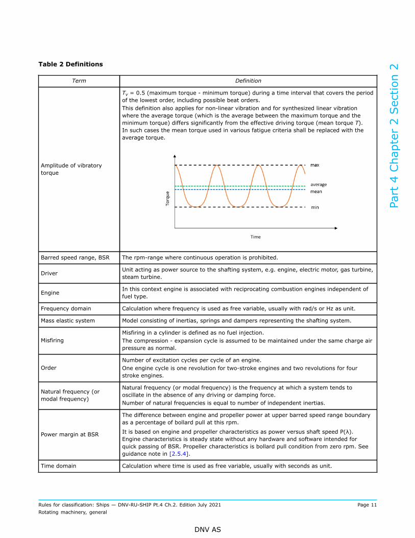
Table 2 Definitions
Term Definition
Amplitude of vibratorytorque
Tv = 0.5 (maximum torque - minimum torque) during a time interval that covers the periodof the lowest order, including possible beat orders.This definition also applies for non-linear vibration and for synthesized linear vibrationwhere the average torque (which is the average between the maximum torque and theminimum torque) differs significantly from the effective driving torque (mean torque T).In such cases the mean torque used in various fatigue criteria shall be replaced with theaverage torque.
Barred speed range, BSR The rpm-range where continuous operation is prohibited.
Driver Unit acting as power source to the shafting system, e.g. engine, electric motor, gas turbine,steam turbine.
Engine In this context engine is associated with reciprocating combustion engines independent offuel type.
Frequency domain Calculation where frequency is used as free variable, usually with rad/s or Hz as unit.
Mass elastic system Model consisting of inertias, springs and dampers representing the shafting system.
MisfiringMisfiring in a cylinder is defined as no fuel injection.The compression - expansion cycle is assumed to be maintained under the same charge airpressure as normal.
OrderNumber of excitation cycles per cycle of an engine.One engine cycle is one revolution for two-stroke engines and two revolutions for fourstroke engines.
Natural frequency (ormodal frequency)
Natural frequency (or modal frequency) is the frequency at which a system tends tooscillate in the absence of any driving or damping force.Number of natural frequencies is equal to number of independent inertias.
Power margin at BSR
The difference between engine and propeller power at upper barred speed range boundaryas a percentage of bollard pull at this rpm.
It is based on engine and propeller characteristics as power versus shaft speed P(λ).Engine characteristics is steady state without any hardware and software intended forquick passing of BSR. Propeller characteristics is bollard pull condition from zero rpm. Seeguidance note in [2.5.4].
Time domain Calculation where time is used as free variable, usually with seconds as unit.
Part 4 Chapter 2 Section 2
Rules for classification: Ships — DNV-RU-SHIP Pt.4 Ch.2. Edition July 2021 Page 11Rotating machinery, general
DNV AS
Term Definition
Transient torsional vibration
Non periodic external excitation of the system. In this context it is associated withoperations as:
— acceleration or deceleration through a barred speed range— starting and stopping operations, especially when driven inertia is multiple of drivers
inertia— clutching in— short circuit in PTO driven generators, especially when Kdyn/T0 > 10 in the PTO branch— propeller out of water and water jet aeration— ice impact dependent of ice class notation— system instability.
The latter condition is in principle a transient condition even if it occurs at constant speedbecause the excitation increases due to the feedback from the speed governor.
Vibration mode shape Pattern with non-dimensional angular displacements of inertias along the shafting for agiven natural frequency.
1.3 Ice class
1.3.1 Ice class notations are presented in Table 3:
Table 3 Ice class notations
Rule reference Class Notations
Pt.5 Ch.10 Sec.10 Icebreaker Icebreaker
Pt.6 Ch.6 Sec.2 Basic ice strengthening Ice(C), Ice(E)
Pt.6 Ch.6 Sec.3 Ice strengthening for theNorthern Baltic Ice(1A*), Ice(1A), Ice(1B), Ice(1C)
Pt.6 Ch.6 Sec.7 Polar class PC(1), PC(2), PC(3), PC(4), PC(5), PC(6), PC(7),
All ice class notations except basic ice strengthening require response torsional vibration analysis due topropeller ice impact excitations. Definition of loads and how to apply them are found in the respective ice rulechapters.
1.4 Documentation requirements
1.4.1 Documentation shall be submitted as required by Table 4.Part 4 Chapter 2 Section 2
Rules for classification: Ships — DNV-RU-SHIP Pt.4 Ch.2. Edition July 2021 Page 12Rotating machinery, general
DNV AS
Table 4 Documentation requirements
Object Document type Additional description Info
C040 – Design analysis Forced vibration calculation, see [2.3] AP
C040 – Design analysisSystems with large transients.Forced vibration in time domain, see [2.4]
AP, R
C040 – Design analysis Fatigue calculation AP, R
Conventional propulsionarrangement
Z266 – Measurement report Measurement of torsional vibrations ifrequested during approval AP, R
C040 – Design analysis Forced vibration calculation, see [2.3]***) AP
C040 – Design analysisSystems with large transients.Forced vibration in time domain, see [2.4]
AP, RPropulsion and steeringthruster arrangement
Z266 – Measurement report Measurement of torsional vibrations ifrequested during approval AP, R
C040 – Design analysis Tunnel thruster – hydraulic or electric driven.Free vibration calculation, see [2.2]*) AP
C040 – Design analysisAll other manoeuvring thrusters.Forced vibration calculation, see [2.3]*)
AP
C040 – Design analysisSystems with large transients.Forced vibration in time domain, see [2.4]*)
AP, R
Manoeuvring thrusterarrangement
Z266 – Measurement report Measurement of torsional vibrations ifrequested during approval *) AP, R
C040 – Design analysis Forced vibration calculation, see [2.3] **) AP
C040 – Design analysisSystems with large transients.Forced vibration in time domain, see [2.4] **)
AP, RElectric power generation
Z266 – Measurement report Measurement of torsional vibrations ifrequested during approval **) AP, R
C040 – Design analysis Forced vibration calculation, see [2.3] **) APEmergency electric powergeneration Z266 – Measurement report Measurement of torsional vibrations if
requested during approval **) AP, R
AP = For approval; FI = For information; R = On request
*) Not required for auxiliary thrusters of 300 kW or less as these have no certification requirements. Thrusters usedfor dynamic positioning is not auxiliary.
**) Generator set not used for propulsion is defined as auxiliary and not scope of approval if less than 200 kW.
***) Podded thrusters: Forced vibration calculation not required if lowest natural frequency is above 2nd blade orderpropeller excitation. Free vibration calculation to be presented.
1.4.2 For general requirements to documentation, including definition of the info codes, see DNV-CG-0550Sec.6.
1.4.3 For a full definition of the documentation types, see DNV-CG-0550 Sec.5.
Part 4 Chapter 2 Section 2
Rules for classification: Ships — DNV-RU-SHIP Pt.4 Ch.2. Edition July 2021 Page 13Rotating machinery, general
DNV AS
2 Calculation
2.1 General2.1.1 Analysis conclusionAll analysis reports shall have a conclusion. In case of forced vibration analysis the conclusion shall be basedon a comparison between calculated dynamic response and the permissible values for all the sensitive partsin the plant. Assumptions, conditions and restrictions shall be presented.
2.1.2 Input data quality
2.1.2.1 GeneralParameters of importance which are uncertain, varying or nonlinear are handled by use of extreme values.It is not required to perform calculations with all combinations of these extreme data, but as a minimum theinfluence shall be quantitatively considered and also addressed in the conclusions.
2.1.2.2 Uncertain parametersVariation of essential data such as dynamic characteristics of elastic couplings and dampers shall beconsidered. Especially rubber couplings and certain types of vibration dampers may have wide tolerances ofstiffness and damping.
2.1.2.3 Variation of parameter valuesFor components where the stiffeners is dependent on vibratory torque and/or temperature (as a consequenceof power los), calculation where these dependencies are included may be requested.
2.1.2.4 Nonlinear characteristicsSystems with components having a strong nonlinear characteristic within the operation range with largeinfluence on the system dynamics shall be simulated in time domain.
2.1.2.5 Source of dataThe source of all essential data shall be listed in the vibration calculation report. For data that cannot begiven as constant parameters, the assumed parameter dependency and tolerance range shall be specified.
2.2 Free vibration2.2.1 Analysis contentNatural frequency calculations of the complete system are required. These shall include tables of relativedisplacement amplitudes, relative inertia torques, vector sums and, if used later, also their phase angles.
2.2.1.1 Specification of input dataMass elastic system: Moments of inertia and inertia-less torsional elasticity/stiffness for each element in thecomplete system.
2.2.1.2 Presentation of results
— Tables: relative displacement amplitudes, relative inertia torques, vector sums and, if used later, also theirphase angles.
— Graphs: vibration mode shapes.
2.2.2 Calculation methodCalculation of relevant natural frequencies and their corresponding mode shapes shall be carried out byrecognised calculation methods.
Part 4 Chapter 2 Section 2
Rules for classification: Ships — DNV-RU-SHIP Pt.4 Ch.2. Edition July 2021 Page 14Rotating machinery, general
DNV AS
Guidance note:Examples of recognised methods obtaining natural frequencies and their mode shapes are methodologies for direct matrixsolutions calculating eigenvalues. Alternatively, approximate methods as the iterative Holzer’s method can be used. Damping hasvery little effect on natural frequency of the system, and hence the calculations for natural frequencies may be made on the basisof no damping.
---e-n-d---o-f---g-u-i-d-a-n-c-e---n-o-t-e---
2.3 Forced vibration frequency domain2.3.1 Analysis content
2.3.1.1 Free vibrationForced vibration shall include free vibration calculation see [2.2].
2.3.1.2 Specification of input dataData to be specified as applicable:
— Engine: engine maker including type designation, rated power, rated speed, cycles per revolution, design(in-line/V-type), number of cylinders, firing order, cylinder diameter, stroke, stroke to connecting rodratio, oscillating mass of one crank gear, excitation see [2.3.3].
— Vibration damper: type, damping coefficient, moments of inertia, dynamic stiffness.— Elastic couplings: type, damping coefficient, moments of inertia, dynamic stiffness.— Reduction/power take off (PTO) gears: type, moment of inertia for wheels and pinions, individual gear'sratios per mesh, effective stiffness.
— Shafting: shaft diameter of crankshafts, intermediate shafts, gear shafts, thrust shafts and propellershafts.
— Propeller: type, diameter, number of blades, pitch and expanded area ratio, moment of inertia in air,moment of inertia of entrained water (for zero and full pitch for CP propellers).
— Mass elastic system: values of all inertias, stiffnesses and damping values including propeller damping.
2.3.1.3 Presentation of outputThe analysis report shall include:
— The results of the forced torsional vibration calculations shall be presented as relevant for the variouscomponents in the system.
— The results shall be presented as synthesis, including amplitude from the orders representing the largestcontributions.
— The results shall be presented by graphs including acceptance values, see [2.5].— Barred speed range, as applicable— Where barred speed range is specified:
— maximum time for passing shall be specified, and within acceptance criteria [2.5.3]
— power margin value with associated engine and propeller curves.Guidance note:For propeller moment of inertia for entrained water, see requirements in Ch.5 Sec.1 [1.2.5].
---e-n-d---o-f---g-u-i-d-a-n-c-e---n-o-t-e---
2.3.2 Calculation method and model
2.3.2.1 Method and mass elastic systemThe forced torsional vibration shall be calculated by means of linear differential equations, one for eachlumped mass. Each mass shall be described by its inertia, connected by torsional springs to adjacent masses,
Part 4 Chapter 2 Section 2
Rules for classification: Ships — DNV-RU-SHIP Pt.4 Ch.2. Edition July 2021 Page 15Rotating machinery, general
DNV AS
damping described as absolute (mass) damping and relative (shaft) damping, and excitation applied onmass. Other recognized methods may be accepted upon request.
2.3.2.2 Representative parameter valuesThe parameters used in vibration calculations shall be representative for the actual speed, mean torque,frequency, temperature, and vibratory torque. The latter implies that if an element is strongly dependent onthe level of the vibratory torque and used in a linear vibration calculation, then the whole calculation may bemade by iteration.
2.3.2.3 Two-stroke engineEngine designer’s model and parameters shall be applied.
2.3.2.4 Propeller dampingIn order to best represent the damping properties of a propeller, the Archer’s or Frahm’s approach withtorque dependent damping coefficients should be used. Alternative methods using a dynamic magnifier orSchwanecke’s empirical approach or other approaches shall be subject to special consideration. For planingcrafts damping shall be based on derivation of the actual torque characteristics, see guidance note.
Guidance note:Propeller damping is a consequence of the propeller’s torque absorption characteristics, defined as C = dT/dω, where T is absorbed
torque and ω=(2πn/60). The torque characteristic for non-planning vessels can be formulated as T = nµ, where μ is 2 in steadystate condition, but is somewhat higher due to the superimposed vibratory torque.
The Archer number is defined as a= μ(60/2π). The corresponding Frahm number is Q ≈ a/9,545. Archer number is dependingon the actual propeller design and load, but is typically in the range 24-30 for conventional propellers. Dynamic magnifier forabsolute damping is defined as M = Jω/C, where J is propeller inertia and ω is actual vibration frequency. The correspondingrelative damping is ζ = (ω/ωn)/2M. Dynamic magnifier or relative damping should only be applied based on experience frommeasurements of similar plants.
---e-n-d---o-f---g-u-i-d-a-n-c-e---n-o-t-e---
2.3.3 Excitation
2.3.3.1 Two-stroke engineEngine excitation shall be based on harmonic tables of tangential crank pressure from engine designerrelevant for the actual engine with respect to type approval. Alternatively it can be based on measurementsof cylinder pressure for the actual engine.
2.3.3.2 Four stroke engineIn addition to the methods for two-stroke engines, simplified methods with generic predefined pressure-timecharacteristics based on main engine data may be accepted.
2.3.3.3 Propeller excitationPropeller excitation can be taken as a percentage of the actual mean torque according to Table 5 unless othervalues are substantiated by the propeller manufacturer. The values are representative for max continuousforward operation. Propeller excitation for extreme steering manoeuvres of azimuth thrusters shall be takenas three (3) times the excitation in Table 5, unless other figures can be documented.
Table 5 Propeller excitation as percent of mean torque
Number of blades Blade frequency Double blade frequency
3 8% 2%
4 6% 2%
5 4% 1.5%
6 4% 1.5%
Part 4 Chapter 2 Section 2
Rules for classification: Ships — DNV-RU-SHIP Pt.4 Ch.2. Edition July 2021 Page 16Rotating machinery, general
DNV AS
Systems where propeller phase is used actively in reducing response.If propeller excitation is used for partial compensation of the engine's excitation of same harmonic order (i.e.propeller phase optimization), this will require a specific computational fluid dynamics calculation (CFD) forthe actual project, alternatively use 50% the table values.
2.3.3.4 Other excitationsOther excitation sources as electric drive control system, water jet impeller pulses, universal joints (secondorder), etc., may be considered when it influences the system behaviour.
2.3.4 Conditions
— normal operation. For engines, this shall be applied as uniform pressure distribution over all cylinders— misfiring operation, only applicable for engines— where the installation allows various operation modes, the torsional vibration characteristics shall beinvestigated for all possible modes, see guidance note.Guidance note:Examples of designs to investigate are installations fitted with controllable pitch propellers for zero and full pitch, power takeoff gear integrated in the main gear or at the forward crankshaft end for loaded and idling generator, clutches for engaged anddisengaged branches.
---e-n-d---o-f---g-u-i-d-a-n-c-e---n-o-t-e---
2.3.4.1 Selection of misfiring cylinderFor calculation in misfiring condition the misfiring cylinder shall be selected as follows:
— for vibration modes and orders with vector sums almost equal zero, any cylinder may be selected— for vibration modes with significant vector sums (e.g. > 0.1 relative to maximum cylinder amplitude)either:
— the cylinder which has the opposite phase angle of the vector sum should be selected or— calculating all combinations and presenting the worst.
2.4 Forced vibration time domain2.4.1 Analysis content
2.4.1.1 Free vibrationForced vibration shall include free vibration calculation, see [2.2].
2.4.1.2 Specification of input dataEngine data to be specified as applicable; brand, model, bore, stroke, piston rod length, number of cylinders,V-angle, firing sequence and max rpm.
2.4.2 Calculation method and model
2.4.2.1 Method and mass elastic systemThe forced torsional vibration shall be calculated by numerical integration of differential equations as foundrelevant for the system modelled.
2.4.2.2 Simplified modelThe mass elastic system for numeric simulation can be simplified in order to remove high natural frequencies.It is required to verify by natural frequency calculations that the simplified system has approximately thesame lower (only the important) frequencies as the detailed system.
Part 4 Chapter 2 Section 2
Rules for classification: Ships — DNV-RU-SHIP Pt.4 Ch.2. Edition July 2021 Page 17Rotating machinery, general
DNV AS
2.4.2.3 Presentation of resultsSimulation results shall be presented by graphs. Resolution and choice of parameters shall reflect theintention of the simulation.
2.4.3 Relevant cases for simulation
2.4.3.1 GeneralThe result of transient vibration documentation shall contain the peak vibration level and an estimation of theequivalent number of cycles. The acceptance criterion is the peak torque (or stress) and the correspondingequivalent number of cycles that shall be used for the shaft calculations.The equivalent number of cycles is defined as the number that results in the same accumulated partialdamage (Miner’s theory) as the real load spectrum. A detailed method for evaluating the equivalent numberof cycles is presented in DNV-CG-0038.Examples of scenario which may be relevant for transient vibration simulations are given in [2.4.3.2] to[2.4.3.6] below.
2.4.3.2 Ice impact loadsDynamic response from ice impact loads shall be simulated in the time domain when:
— required by the ice class rules— ice load may result in reduced shaft speed, which may be harmful or impose severe operationallimitations.Guidance note:Polar class rules require transient torsional vibration analysis Pt.6 Ch.6 Sec.7 [11.6.2], which in practice means time domainsimulation. Baltic ice class rules open up for both time domain and frequency domain analysis, but states that the intention isestimation of extreme load Pt.6 Ch.6 Sec.3 [15.5.3.2]. Ice going vessels will also face an increased resistance which may besimilar to bollard pull condition. A drop in shaft speed into a barred speed range may limit operation, and also available power ifthe engine has to go below the barred speed range.
---e-n-d---o-f---g-u-i-d-a-n-c-e---n-o-t-e---
2.4.3.3 Large inertia loadsFor plants that have a major critical resonance below idling speed and a low ratio of engine inertia to drivenmachinery inertia, the transient vibration torque shall be considered. This applies e.g. to diesel generator setswith highly elastic couplings and similar propulsion plants without clutch.
2.4.3.4 Clutching-inThe calculation of the system shall determine:
— the peak torque in couplings and gears— the first decreasing torque amplitudes— the heat developed in the clutch— the flash power in the clutch.
The clutch parameters such as the actuation pressure-time characteristics and if necessary also the changingcoefficient of friction shall be used in the calculation.The results shall not exceed the permissible peak torques and amplitudes in couplings and gears in additionto the permissible heat (J) and flash power (W) in the clutch.Torque measurements during the clutching-in may be required. This applies when calculations indicate peaktorques or amplitudes near the approved limits.
2.4.3.5 Short circuit in PTO driven generatorsA possible short circuit in a generator shall not be detrimental for the power transmitting elements such ascouplings and gears. The purpose of the calculation shall determine the peak torques and amplitudes thatoccur before the safety system (circuit breaker) is in action. The duration to be considered is one (1) second.
Part 4 Chapter 2 Section 2
Rules for classification: Ships — DNV-RU-SHIP Pt.4 Ch.2. Edition July 2021 Page 18Rotating machinery, general
DNV AS
Guidance note:If the excitation torque (in the air gap between rotor and stator) is not specified, it can be assumed as:
T = T0 [10 e-t/0.4 sin(Ω t) – 5 e-t/0.4 sin(2Ω t)]
where:
Ω/2π = the electric net frequency (50 or 60 Hz)
t = time in s.
---e-n-d---o-f---g-u-i-d-a-n-c-e---n-o-t-e---
2.4.3.6 Influence of speed governorWhen the speed governor influence has been taken into account it shall be done in the time domain.
2.5 Acceptance criteriaIf any result is close to the acceptance limit and there are uncertainties in the calculations, vibrationmeasurements may be required, see [4].
2.5.1 Availability of main functionsIn specifying prohibited ranges of operation due consideration shall be given to ensure that the navigatingand manoeuvering functions are not severely restricted.
2.5.2 Determination of barred speed rangeSpeed ranges or operating conditions where the following acceptance criteria are exceeded, shall bebarred for continuous operation. Corresponding signboards shall be fitted at all manoeuvring stands and alltachometers marked with red. The tachometers shall be accurate within the tolerance +/-0.01 n0. A barredspeed range above λ=0.8 is not permitted.The width of a barred speed range shall be determined as follows:
— range where permissible values are exceeded— extend with tachometer tolerance in both ends— further extension in case of unstable engine operation at any end of the barred range.
Guidance note:For 2-stroke fixed pitch plants the width of the barred speed range should not be made unnecessary wide because this can resultin a too slow passage with the consequence of higher vibratory stress level and increased number of cycles with high stress level.
---e-n-d---o-f---g-u-i-d-a-n-c-e---n-o-t-e---
2.5.3 Time for passing barred speed rangeBarred speed range shall be passed rapidly and within the approved passing time tBSR. Unless otherwise issubstantiated by a detailed fatigue evaluation of the propulsion shafting system, tBSR shall not exceed:
Where:
τVmax is peak torsional (steady state) stress [N/mm2] in the intermediate shaft within barred speed range(calculated or measured, see also [3.1.2]).
τ T is maximum allowable transient stress [N/mm2], as calculated from relevant shafting rules (IACS UR M68or τ max in DNV-CG-0038).tMR is a passing time allowance [s] for intermediate shafts with design features ensuring a low stressconcentration factor, SCF ≤ 1.1. In such cases tMR may be taken as 10.0 [s]. For flanged shafts this requiresa multi radii fillet design (see also Ch.4 Sec.1 [2.2.7.3] and for further explanation DNV-CG-0038). In this
Part 4 Chapter 2 Section 2
Rules for classification: Ships — DNV-RU-SHIP Pt.4 Ch.2. Edition July 2021 Page 19Rotating machinery, general
DNV AS
respect, keyless shrink fit connections are also considered to have SCF ≤ 1.1. tMR shall be taken as 0.0 [s] forall other designs features.
The above is on the condition that the propeller shaft demonstrates the same or higher relative margin vs.the transient stress criterion as the intermediate shaft. Otherwise the ratio between τVmax and τT shall beadjusted accordingly, in the formula above.
Guidance note:The formulation for tBSR is outlined from IACS UR M68, considering the slope of the S-N curve as derived from the allowabletransient stress level within BSR, assumed to correspond to 104 load cycles and the allowable continuous stress amplitude levelconsidered for 3·106 load cycles. As the formulations for allowable stresses in M68 implicitly include assumptions related to
correlation between speed ratio ( λ) and number of accumulated cycles during a 'rapid' passing of BSR, an additional margin isbuilt into the formulation for tBSR, by means of increasing the slope of the initially constructed S-N curve with a factor of 1.5. Thisfacilitates a safe operation for installations with a longer passing time. For flanged intermediate shafts, the shaft feature designfactor (CK) in M68 equals 1.0, and the ratio between allowable transient and continuous stress amplitude becomes 1.7. The value7.2 is in line with material properties for typical steel qualities and shall be applied independent of CK value.Based on the M68 approach for shaft fatigue, the formulation for the exponent (slope of S-N curve) in the formula becomes:
For installations where the intermediate shaft peak stresses within BSR reach the maximum allowable transient stresses, DNVdefines 5 [s] as 'rapid passing' and this is taken as basis for the TBSR formulation.Compliance with the requirement in [2.5.3] is on this basis considered to be in line with corresponding requirements related to'rapid' passing of BSR in IACS UR M51 and M68.
---e-n-d---o-f---g-u-i-d-a-n-c-e---n-o-t-e---
2.5.4 Power margin at BSRPower margin at upper end of the barred speed range shall be sufficient to ensure a reasonable passing timeof BSR in all expected operating conditions.10% power margin is considered sufficient. However, if lower margin may be accepted, supported byexperience and/or extended analysis.It is not required to verify the power margin at ship board testing.
Guidance note:Main motivation for power margin is to have a requirement at design stage ensuring passing barred speed range within approvedtime tBSR, see [2.5.3].The predicted power margin (see Figure 1) is found comparing available engine power curve as provided by the engine maker tothe bollard pull curve for the designed propeller. The bollard pull curve is constructed according to the propeller law, with a bollardpull margin vs. the free running propeller curve (including light running margin, LRM).Bollard pull margin is to some extent design dependent. However, a default bollard pull margin of 17.5% is the basis for the powermargin requirement. Lower bollard pull margin may be applied when supported by more detailed propeller calculations and/orexperience data. In some cases, it is recommended to increase the bollard pull margin beyond the default value, in particular forships with relatively high service speed as these designs may have larger difference between bollard pull and free running propellercharacteristics.
---e-n-d---o-f---g-u-i-d-a-n-c-e---n-o-t-e---
Part 4 Chapter 2 Section 2
Rules for classification: Ships — DNV-RU-SHIP Pt.4 Ch.2. Edition July 2021 Page 20Rotating machinery, general
DNV AS
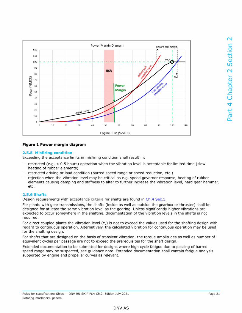
Figure 1 Power margin diagram
2.5.5 Misfiring conditionExceeding the acceptance limits in misfiring condition shall result in:
— restricted (e.g. < 0.5 hours) operation when the vibration level is acceptable for limited time (slowheating of rubber elements)
— restricted driving or load condition (barred speed range or speed reduction, etc.)— rejection when the vibration level may be critical as e.g. speed governor response, heating of rubberelements causing damping and stiffness to alter to further increase the vibration level, hard gear hammer,etc.
2.5.6 ShaftsDesign requirements with acceptance criteria for shafts are found in Ch.4 Sec.1.For plants with gear transmissions, the shafts (inside as well as outside the gearbox or thruster) shall bedesigned for at least the same vibration level as the gearing. Unless significantly higher vibrations areexpected to occur somewhere in the shafting, documentation of the vibration levels in the shafts is notrequired.For direct coupled plants the vibration level (τv) is not to exceed the values used for the shafting design withregard to continuous operation. Alternatively, the calculated vibration for continuous operation may be usedfor the shafting design.For shafts that are designed on the basis of transient vibration, the torque amplitudes as well as number ofequivalent cycles per passage are not to exceed the prerequisites for the shaft design.Extended documentation to be submitted for designs where high cycle fatigue due to passing of barredspeed range may be suspected, see guidance note. Extended documentation shall contain fatigue analysissupported by engine and propeller curves as relevant.
Part 4 Chapter 2 Section 2
Rules for classification: Ships — DNV-RU-SHIP Pt.4 Ch.2. Edition July 2021 Page 21Rotating machinery, general
DNV AS
Guidance note:In this context high cycle fatigue is expected when high transient stress amplitudes are combined with a large number of cycles.Total number of cycles is dependent of cycles for each passing of barred speed range (BSR) and the vessel's operation profile.DNV-CG-0038 Calculation of shafts in marine applications may be used for fatigue analysis. DNV-CG-0038 calculates fatiguecapacity based on Wöhler curve (S-N curve) and Miner sum.
---e-n-d---o-f---g-u-i-d-a-n-c-e---n-o-t-e---
2.5.7 CrankshaftsDesign requirements and acceptance criteria for crankshafts are found in Ch.3 Sec.1.The permissible vibration torque (or shear stresses) and peak torque (only applicable to semi-built shafts)are determined in connection with the engine approval. Other criteria may also apply, such as acceleration atmass for cam drive branch or journal movements in bearings.
2.5.8 Vibration dampersDesign requirements and acceptance criteria for dampers are found in Ch.3 Sec.1.Depending on the type of damper (viscous, rubber, steel spring) the following shall be considered:
— dissipated power (all kinds)— vibration torque (rubber type and some steel spring types)— vibration angle (some steel spring types).
The limits specified in the respective type approvals apply.
2.5.9 Torsional elastic couplingsDesign requirements and acceptance criteria for torsional elastic couplings are found in Ch.4 Sec.5.Torsional elastic couplings have design limitations with respect to:
— dissipated power— vibration torque.
These limits are for continuous operation. Higher values may be accepted for a limited time of operation iftwist amplitudes are monitored.Transient vibration which occur occasionally (i.e. less than 50 000 times) such as clutching-in is not to exceedneither TKmax1 nor ΔTKmax.Transient vibration which occur very infrequently indeed such as short circuit [2.4.3] are not to exceedTKmax2.Power loss need not be considered for transient operation.
2.5.10 Other couplingsDesign requirements and acceptance criteria for actual components are found in Ch.4 Sec.4.For other couplings and similar components such as membrane couplings, universal joints, link couplings,elements of composite materials, etc. the approved vibration torque shall not be exceeded.Tooth couplings are limited with regard to cyclic torque reversals. The negative torque is not to exceed 20%of T0 unless especially approved.
2.5.11 Gear transmissionsDesign requirements and acceptance criteria for gear transmissions are found in Ch.4 Sec.2.The permissible vibration torque in gear transmissions is limited as:
1) In the full speed and load range (> 90% of rated speed and load) the vibration torque is not to exceed(KA - 1)·T0 where KA is the application factor used in the gear transmission approval.
2) The vibration torque is limited to 35% of T0 throughout the entire operation range.3) Gear hammer (negative torque) is not permitted except in unloaded power take off branches, where
20% of T0 (referred to the subject shaft speed) and 25% short duration misfiring is permitted.4) Transient vibrations shall not cause negative torques of more than 25% of T0.
Part 4 Chapter 2 Section 2
Rules for classification: Ships — DNV-RU-SHIP Pt.4 Ch.2. Edition July 2021 Page 22Rotating machinery, general
DNV AS
5) Transient peak torques shall neither be higher than (1.5 T0) nor the approved value (KAP T0).
2.5.12 Shrink fits including propeller fittingDesign requirements and acceptance criteria for shrink fits are found in Ch.4 Sec.1.The estimated vibration torque shall not exceed the value used in the approval of the shrink fit connection.Permissible vibration torque in shrink fit connections shall be considered for direct coupled plants and whenthe peak torque in a barred speed range exceeds the peak torque at full load. Peak torque values duringmisfiring operation shall be subject to special consideration.
2.5.13 PropellersDesign requirements and acceptance criteria for propellers are found in Ch.5 Sec.1.No specific limitations apply unless specifically mentioned in connection with the propeller approval.
2.5.14 ThrustersSee Ch.5 Sec.3.
2.5.15 Electric rotating machines generators, pumps, compressors, etc.The vibration level shall not exceed any limitation specified by designer of the electric generator or motor.
2.5.16 Speed governorThe vibration levels at the sensor location of flexibly coupled propulsion engines shall not exceed the valuespecified by the engine manufacturer. If no value is specified and approved, tests and measurements shall bemade in order to verify that the governor response is insignificant.
3 Shipboard testing
3.1 Check of barred speed range3.1.1 Demonstration testWhere a barred speed range (BSR) is required, passages through this BSR, both accelerating anddecelerating, shall be demonstrated. This also includes when passing through the BSR in reverse rotationaldirection, especially during the stopping test. This applies both for manual and automatic passing-throughsystems.
3.1.2 Time recordingThe BSR passing time shall be recorded. Passing time for accelerating ahead shall be equal to or belowthe times specified in the approved documentation, see also [2.5.3]. Measurements shall be taken in trialcondition.
Guidance note:In cases where vibratory stresses are documented by strain gauge measurements and measured steady state stress values [4.2.5]are less than calculated in approved documentation [4.2.5], the maximum allowable passing time may be adjusted accordingly,according to the formulation in [2.5.3].
---e-n-d---o-f---g-u-i-d-a-n-c-e---n-o-t-e---
3.1.3 Border stabilityThe engine shall be checked for stable running (steady fuel index) at both upper and lower borders of thebarred speed range. Steady fuel index means an oscillation range less than 5% of the effective stroke (idle tofull index).
For controllable pitch propellers, this shall be tested with both zero and full pitch unless otherwise agreed.
Part 4 Chapter 2 Section 2
Rules for classification: Ships — DNV-RU-SHIP Pt.4 Ch.2. Edition July 2021 Page 23Rotating machinery, general
DNV AS
3.1.4 Quick pass throughPassing through a barred speed range shall be made in an optimum way. This means as quickly as possible.If a specific procedure is given in the torsional vibration calculations, this shall be verified under the foreseenoperational conditions.
3.1.5 MisfireAdditional speed restrictions specified for misfire condition shall be verified, see [3.1.3], [4.2.4] and [4.2.5].Only applicable for conditions within engine limitations.
3.1.6 SignboardWhen a barred speed range is required, signboards describing how to pass through shall be provided at allengine operating stands.
3.1.7 AlarmFor all installations where a barred speed range is introduced, an alarm shall be installed and initiated in theengine control room when passing time exceeds the approved value, see [2.5.3] and Ch.3 Sec.1 Table 10[pos.10].A reasonable delay time is accepted.
Guidance note:A delay time of 5 seconds or 50% of approved passing time, whichever is the highest is considered reasonable. The intention withthe alarm is to alert the crew members about undesirable operating conditions for the propulsion shafting, and by that facilitate amore favorable operation to the extent possible.
---e-n-d---o-f---g-u-i-d-a-n-c-e---n-o-t-e---
Guidance note:Requirements to procedure and measurements are found in [4]. Compliance with IACS UR-M51.4 is achieved by fulfilling [3.1] and[4].
---e-n-d---o-f---g-u-i-d-a-n-c-e---n-o-t-e---
3.2 Check of gear hammerReduction gears and power take off gears shall be detected for gear hammer in misfiring condition inranges specified in connection with the approval. Speed ranges where gear hammer occurs shall be barredfor continuous operation. However, in power take off gears light gear hammer in unloaded condition isacceptable.
3.3 Check of stability for systems with flexible couplings by use of misfiringEngines with elastic couplings shall be checked for stability of the speed governing system when provoked bymisfiring. For selection of misfiring cylinder, see approved torsional vibration calculations.Unless otherwise stated in the approved torsional vibration calculations, the following apply for each plant onboard:
— Single engine plant: the entire speed range with either full pitch or combination pitch shall be checked.This may be done by a slow sweep or stepwise speed increase.
— Two-engine plants (with common reduction gear): the same applies, but the misfiring of the enginesshall be combined. This may be done by keeping the selected misfiring for engine one, and first select acylinder at random for the second engine and afterwards select the adjacent cylinder, see guidance note.
— Plants with more than two engines: special considerations apply.— Diesel generator sets shall be checked at a minimum of 50% load and with another set operating inparallel. All sets shall be tested.
— Speed ranges where gear hammer occurs due to one misfiring cylinder shall be restricted for continuousoperation in that operation mode.
Part 4 Chapter 2 Section 2
Rules for classification: Ships — DNV-RU-SHIP Pt.4 Ch.2. Edition July 2021 Page 24Rotating machinery, general
DNV AS
Guidance note:
Explanation to the two engine plant test: This is a test of low order (typical 0.5 order) instability and not two independent failures.Hence, it is important that the two engines have different phase shift after a clutching in-out sequence, and that both enginesare misfiring in order to have enough imbalances to simulate worst case with 0.5 order resonance. Fuel rack oscillations peak topeak (with combined misfiring for twin engines) less than 20% of the effective stroke (idle to full) are normally considered asacceptable. For engines without fuel rack similar parameters are taken from engine monitoring system.
---e-n-d---o-f---g-u-i-d-a-n-c-e---n-o-t-e---
3.4 Check of transients during clutching-in procedureAfter the clutch characteristics (pressure - time) are checked, the clutching-in shall be checked at theminimum respectively the maximum permissible engine speed for clutching-in. The speed governing systemshall respond with quickly damped oscillations.
3.5 Closed loop stabilityThe following may be requested, see type of speed governor:
— type and position of speed sensor.Guidance note:Evaluation of the torsional vibration system should be considered in case of conditions with high vibration at the governor pick upposition.
---e-n-d---o-f---g-u-i-d-a-n-c-e---n-o-t-e---
4 Measurements
4.1 General4.1.1 InstrumentationWhen vibration measurements are required by the Society, the type of instrumentation, location of pickups,signal processing method, and the measurement procedure shall be approved by the Society.
4.1.2 Measurement reportWhen vibration measurements are required by the Society, a complete report containing results fromunfiltered signals (e.g. shaft stresses) as well as processed signals (e.g. frequency analyses) shall besubmitted for approval.
4.2 Barred speed range4.2.1 Measurements
— When a barred speed range is specified, the torsional vibrations shall be verified by means ofmeasurements, unless otherwise is specially agreed.
— Strain gauge measurements are required if calculated peak stress in approved TVC is higher than 85% ofallowed transient stress ( ), and upon request. For other installations encoder is accepted.
Guidance note:Measurements are only required for the first ship in a series, unless design modifications are carried out.
---e-n-d---o-f---g-u-i-d-a-n-c-e---n-o-t-e---
Part 4 Chapter 2 Section 2
Rules for classification: Ships — DNV-RU-SHIP Pt.4 Ch.2. Edition July 2021 Page 25Rotating machinery, general
DNV AS
4.2.2 System completionAll tuning of hardware and software shall be completed before verification measurements are carried out.
4.2.3 Parameters to measure
— torsional stress in shaft, alternatively vibratory angles when encoder is accepted— shaft speed [rpm]— pitch if CP-propeller, or alternatively to be noted.
Upon request:
— fuel index or "fuel command used for injection" for common rail engines.Guidance note:Fuel index: amplitude at BSR borders should be less than 5% of full fuel index (effective stroke idle to full stroke, or 'fuel commandused for injection'-effective range for common rail engines). Higher values may be accepted dependent of ship type, conditions andlambda value.
---e-n-d---o-f---g-u-i-d-a-n-c-e---n-o-t-e---
4.2.4 Parameters to register
— ship speed (STW)— wind speed or BF no. and wind direction— average wave height or sea state (approx.)— draft (Fwd and Aft)— sea depth— ship course (heading).
It is not required to implement the above parameters in measurement system. Parameters may be notedmanually and included in the report.
4.2.5 Measure steady state vibrations in ahead conditionEach measurement shall reach steady state condition with respect to ship speed and power/torque.Resolution of rpm at resonance shall be as high as possible from the ECU. Measurements can alternatively becarried out as a slow-ramp, where ramp speed is equivalent to a steady state condition. Points to be verified:
1) steady state vibration amplitude at lower BSR borders2) steady state vibration amplitude at resonance rpm3) steady state vibration amplitude at upper BSR borders.
If measured steady state stress amplitudes at resonance are higher than in the approved TVC, a report withmeasured values shall be submitted to the society for re-evaluation of stress level and passing time.
Guidance note:Scope of measurement programme in misfire condition is dependent of consequences. Main intention is to verify rpm boundaries,measurement of resonance in misfiring condition is not mandatory. Verification of peak values may be required.
---e-n-d---o-f---g-u-i-d-a-n-c-e---n-o-t-e---
4.2.6 Passing barred speed range accelerating ahead
1) Start at telegraph setting at the closest telegraph setting position below lower border of BSR, allow theship to accelerate to steady ship speed.
2) Accelerate through BSR as recommended or as programmed in ECU using software and hardwareintended for this operation.
3) Measure time used passing BSR from lower to upper rpm limits and check against approved maximumtime tBSR.
If time used to pass the BSR is longer than the approved time, a report with available measurement datashall be submitted to the Society for re-evaluation, see also [2.5.6]. In case transient stress levels have notbeen documented, additional measurements may be required.
Part 4 Chapter 2 Section 2
Rules for classification: Ships — DNV-RU-SHIP Pt.4 Ch.2. Edition July 2021 Page 26Rotating machinery, general
DNV AS
Guidance note:
Propulsion shaft line equipment potentially influencing on passing time, such as PTI, PTO, shaft generators, etc., shall be engagedas relevant for normal operation per design. It shall be specified in a procedure if equipment shall be engaged or disengaged inorder to satisfy passing time requirement tBSR. The requirements of this paragraph are not applicable for misfiring condition if BSRis in the upper rpm range and when the range up to max rpm is barred. Allowable time passing BSR will be evaluated case by casefor installations where it is relevant to operate above the BSR initiated by misfire.
---e-n-d---o-f---g-u-i-d-a-n-c-e---n-o-t-e---
Part 4 Chapter 2 Section 2
Rules for classification: Ships — DNV-RU-SHIP Pt.4 Ch.2. Edition July 2021 Page 27Rotating machinery, general
DNV AS
SECTION 3 LATERAL AND AXIAL SHAFTING VIBRATIONS
1 General
1.1 Application1.1.1 ScopeThe rules in this section apply to all shafting used in rotating machinery for propulsion, power production,steering and manoeuvring independent of type of driver except auxiliary plants with less than 200 kW ratedpower.
1.1.2 Vibration regimesThe following vibration regimes are covered within this section:
— lateral vibrations are handled as whirling, see [2]— axial vibration see [3].
The following regimes are covered in other rule chapters:
— torsional vibrations, see Sec.2— engine flexible mounting, see Ch.3 Sec.1— vibration level as environmental requirement, see Ch.1 Sec.3— class notations related to vibrations, see Pt.6 Ch.8 Sec.1 and Pt.6 Ch.8 Sec.2.
1.1.3 Acceptance criteriaAcceptance criteria for components are found in the respective rule chapters for the components.
1.1.4 Coupled vibrationsAxial vibrations initiated by torsional vibrations can be handled as independent, but with the radialcomponent of excitation from the cylinder forces.
1.1.5 Forced vibration analysisTime domain simulation may be requested in addition to forced vibration calculation in the frequency domainfor transient analysis.
1.2 DefinitionsTable 1 Definitions
Term Definition
axial vibration vibration in the direction of the centre line
counter whirl whirl vibration has opposite direction as the mean shaft rotation
forward whirl whirl vibration has equal direction as the mean shaft rotation
lateral vibration vibration in orthogonal direction to the centre line
order number of excitations per shaft revolution
whirling run out of shaft and shafting components with nodes in the shaft bearings
Part 4 Chapter 2 Section 3
Rules for classification: Ships — DNV-RU-SHIP Pt.4 Ch.2. Edition July 2021 Page 28Rotating machinery, general
DNV AS
1.3 Documentation requirements
1.3.1 Documentation shall be submitted as required by Table 2.
Table 2 Documentation requirements
Object Document type Additional description Info
C040 - Design analysis Lateral vibration *) AP, RConventional propulsion arrangement
C040 - Design analysis Axial vibration *) AP, R
C040 - Design analysis Lateral vibration *) AP, RPropulsion and steering thrusterarrangement C040 - Design analysis Axial vibration *) AP, R
C040 - Design analysis Lateral vibration *) AP, RManoeuvring thruster arrangement
C040 - Design analysis Axial vibration *) AP, R
AP = For approval; R = On request*) Default is free vibration calculation, but more extended calculations may be requested.
Guidance note 1:Lateral vibration calculation may be requested during approval of shaft arrangement. Examples of sensitive designs are shafts withlarge bearing span/shaft diameter ratio, propellers with large overhang from aft most bearing, flexible support of aft most bearingas typical for twin screw designs, large inertias without bearing support, tooth couplings without bending stiffness.
---e-n-d---o-f---g-u-i-d-a-n-c-e---n-o-t-e---
Guidance note 2:Axial vibration calculation may be requested during approval of shaft arrangement. Examples of sensitive designs are long stroketwo-stroke engines without axial damper, shafting with length above 40 m, flexible couplings with interaction between torque andaxial deflection, propeller designs where natural blade bending frequency is equal to natural axial shaft frequency.
---e-n-d---o-f---g-u-i-d-a-n-c-e---n-o-t-e---
1.3.2 For general requirements to documentation, including definition of the info codes, see DNV-CG-0550Sec.6.
1.3.3 For a full definition of the documentation types, see DNV-CG-0550 Sec.5.
1.3.4 Drawings of the complete shafting arrangement shall be included in the design analysis. Typedesignation of prime mover, gear, elastic couplings, driven unit, shaft seals etc. shall be stated on thedrawings. The drawings shall show all main dimensions as diameters and bearing spans, bearing supportsand any supported elements as e.g. oil distribution boxes.
1.3.5 The vibration calculations shall be accompanied by an analysis, which shall compare the result ofthe calculation with the acceptance levels for all components in the system as relevant, and conclude withrespect to possible restrictions. Assumptions, conditions and restrictions shall be presented.
Part 4 Chapter 2 Section 3
Rules for classification: Ships — DNV-RU-SHIP Pt.4 Ch.2. Edition July 2021 Page 29Rotating machinery, general
DNV AS
2 Lateral vibration
2.1 Analysis2.1.1 Extent and method of calculationAs a minimum, the calculations shall include the natural frequencies and mode shapes of the relevantvibration modes.
2.1.2 Uncertain and variable parametersA variation of parameters shall be included in the analysis in case of uncertain or variable importantparameters.
Guidance note:Important but uncertain parameters as stiffness of aft stern tube bearing, resulting bearing load position, bearing load distributionover length (if calculating with distributed bearing reaction), entrained water on propeller, etc. shall be varied within their probablerange and natural frequencies to be presented as corresponding graphs.
---e-n-d---o-f---g-u-i-d-a-n-c-e---n-o-t-e---
2.1.3 Entrained water to propellerCalculation of entrained water shall be presented.
2.1.4 First order acceptance criteriaResonance with the shaft speed (1st order forward whirl) shall have a separation margin of at least 20% tothe operating speed range, see guidance note.
Guidance note:Example: a system with idle at 20 rpm and MCR at 100 rpm shall not have a 1st order fwd whirl in the range 16 rpm to 120 rpm.
---e-n-d---o-f---g-u-i-d-a-n-c-e---n-o-t-e---
2.1.5 Higher order acceptance criteriaResonance caused by propeller blade passing (blade order) shall be avoided in the upper operating speedrange unless it is substantiated that resonance will not cause harmful response, see guidance note.
Guidance note:Approval is based on an over-all evaluation, and resonance should be avoided in the range 80 - 120% of MCR speed. Exceptionsmay be given: along shafting with many bearings is not found sensitive if the propeller is the main excitation source and the modeshape indicates resonance in forward end of shafting. Also bearing designs where good damping is expected, e.g. high bearinglength to diameter ratio combined with a bouncing vibration mode, may justify acceptable resonance response at high rpm.
---e-n-d---o-f---g-u-i-d-a-n-c-e---n-o-t-e---
2.1.6 Presentation of resultsResults shall be presented both in way of numerical values and graphical e.g. as a Campell diagram. Modeshapes of the natural frequencies shall be presented.
3 Axial vibration
3.1 Analysis3.1.1 Extent and method of calculationAs a minimum, the calculations shall include the natural frequencies and mode shapes of the relevantvibration modes.
Part 4 Chapter 2 Section 3
Rules for classification: Ships — DNV-RU-SHIP Pt.4 Ch.2. Edition July 2021 Page 30Rotating machinery, general
DNV AS
3.1.2 Uncertain and variable parametersIf the lowest vibration mode (with the node in the thrust bearing) is of significance to the conclusion, thecalculations shall be made with various thrust bearing stiffness in order to see the influence of an estimationerror.
3.1.3 Acceptance criteria free vibrationIf major critical resonance occurs near or in the operational speed range and no damper is foreseen, forcedaxial vibration calculations shall be required.
3.1.4 Acceptance criteria forced vibrationIn crankshafts, the stresses due to axial vibration shall not exceed the values used in connection with theengine approval. The amplitudes at the front end of the crankshaft shall be within the engine designer’sspecified limit.
3.1.5 Presentation of resultsResults shall be presented both in way of numerical values and graphical of the mode shapes of the naturalfrequencies.
4 Measurements
4.1 Axial vibrationMeasurements of axial vibrations shall be required if major critical resonance occurs near or in theoperational speed range and no damper is foreseen.
4.2 Measurement programWhen vibration measurements are required, the type of instrumentation, location of pick-ups, signalprocessing method, and the measurement procedure shall be approved by the Society.
4.3 Measurement resultsA complete report containing results from unfiltered signals (e.g. shaft stresses) as well as processed signals(e.g. frequency analyses) shall be submitted for approval.
Part 4 Chapter 2 Section 3
Rules for classification: Ships — DNV-RU-SHIP Pt.4 Ch.2. Edition July 2021 Page 31Rotating machinery, general
DNV AS
SECTION 4 SHAFT ALIGNMENT
1 General
1.1 Application
1.1.1 This subsection is only applicable for propulsion plants. For geared plants, the calculations in thissection are only applicable for the low speed shaft line, which shall include the output gear shaft with radialbearings. Vertical shaft alignment is always applicable, while horizontal alignment is applicable upon request.The rule requirements applies to fully submerged propellers.
1.1.2 Calculation versus specificationPropulsion plants as described in [1.3.2] require shaft alignment calculation.All other plants need a shaft alignment specification only, see [1.3.3].
1.1.3 Aft most bearingAcceptance criteria and modelling of aft most bearing are dependent of risk:
— White metal lined aft stern tube bearing which is either double sloped, or has a journal diameter 500 mmor greater, shall fulfil bearing lubrication criteria defined in [2.1.6].
— Stern tube arrangements incorporating a single stern tube bearing only and where alignment calculation isrequired, shall fulfil bearing lubrication criteria defined in [2.1.6].
— Other propulsion plants where alignment calculation is required shall fulfil requirements in [2.1.5].Guidance note:Aft most bearing is in most cases to be understood as aft stern tube bearing, but can also be other designs e.g. strut mountedbearings which are common in twin screw designs without skegs.
---e-n-d---o-f---g-u-i-d-a-n-c-e---n-o-t-e---
1.1.4 SurveyInstallation of propulsion plants requiring a shaft alignment calculation shall be verified by a surveyor.
1.2 DefinitionsTable 1 Definitions
Term Explanation
shaft alignmentspecification
description of the shaft alignment sufficient to carry out the installationIt shall contain a procedure, verification data and offset from a defined reference line.
shaft alignment calculationall information required to evaluate the shaft alignmentIt shall contain a shaft alignment specification in addition to calculations as described in[2].
reference line a straight virtual line defined by two chosen points in order to define vertical and horizontaloffsets
bearing reaction influencenumbers
bearing loads as a consequence of a unit offset of a bearingIt is described by a (N × ) sized table for a model with bearings.
Definitions and symbols used in oil film criteria only are presented in [2.1.6].
Part 4 Chapter 2 Section 4
Rules for classification: Ships — DNV-RU-SHIP Pt.4 Ch.2. Edition July 2021 Page 32Rotating machinery, general
DNV AS
1.3 Documentation1.3.1 Document requirementDocumentation shall be submitted as required by Table 2.
Table 2 Documentation requirements
Object Document type Additional description Info
C040 – Design analysis Shaft alignment calculation when required, see [1.3.2]. AP
C040 – Design analysis Supporting calculation of propeller loads, see [1.3.2]. R (FI)Conventionalpropulsionarrangement
Z170 – Installation manual Shaft alignment specification when calculation is notrequired, see [1.3.3]. FI
AP = For approval; FI = For information; R = On request
1.3.2 Systems requiring shaft alignment calculationShaft alignment calculation report shall be submitted for approval for propulsion plants with one out of thefollowing criteria:
— minimum shaft diameters (low speed side) of 400 mm or greater for single screw and 300 mm for twinscrew
— gear transmissions with more than one pinion driving the output gear wheel, even if there is only onesingle input shaft as for dual split paths
— shaft generator or electrical motor as an integral part of the low speed shaft in diesel engine propulsion— single stern tube bearing arrangement.
Upon request, shaft alignment calculations may also be required for unconventional hull forms, such asasymmetric aft ship, and/or novel propulsion arrangements, such as arrangements incorporating propulsionimprovement devices (PIDs). Alignment calculations may also be required for other plants when these areconsidered sensitive to alignment.Upon request, supporting analysis of propeller loads in normal and/or transient operation may be required,in cases where it is suspected that use of default propeller loads is not sufficient to ensure a robust aft sterntube bearing design.For required content of a shaft alignment calculation report, see [2].
1.3.3 Systems only requiring shaft alignment specificationFor all propulsion plants other than those listed in [1.3.2], a shaft alignment specification shall be submittedfor information. The shaft alignment specification shall include the following items:
— bearing offsets from the defined reference line— bearing slope relative to the defined reference line if different from zero— installation procedure and verification data with tolerances e.g. gap and sag and jacking loads (includingjack correction factors and jack positions) and verification conditions (cold or hot, propeller submersion,etc.).
1.3.4 For general requirements to documentation, including definition of the info codes, see DNV-CG-0550Sec.6.
1.3.5 For a full definition of the documentation types, see DNV-CG-0550 Sec.5.
Part 4 Chapter 2 Section 4
Rules for classification: Ships — DNV-RU-SHIP Pt.4 Ch.2. Edition July 2021 Page 33Rotating machinery, general
DNV AS
2 Calculation
2.1 General2.1.1 Calculation input dataThe shaft alignment calculations shall at minimum include the following input data:
— propulsion plant particulars, e.g. rated power of main engine and propeller shaft rpm— equipment list, i.e. manufacturer and type designation of prime mover, reduction gear (if applicable) andbearings
— geometry data of shafts, couplings and bearings, including reference to relevant drawings. For directcoupled plants, the crankshaft model shall be according to the engine designer's guidelines
— propeller data— bearing clearances.
2.1.2 Alignment conditionsThe shaft alignment calculations shall include the following conditions:
— alignment condition (during erection of shafting)— cold, static, afloat, fully submerged propeller— hot, static, afloat, fully submerged propeller— hot, running with hydrodynamic propeller loads.
For geared shafting systems:
— running conditions as required to verify gear acceptance criteria— all relevant combinations of prime mover operation— horizontal alignment is upon request.
2.1.3 Influence parametersThe shaft alignment calculations shall take into account the influence of:
— buoyancy of propeller— thermal rise of machinery components (including rise caused by heated tanks in double bottom and otherpossible heat sources)
— gear loads (horizontal and vertical forces and bending moments)— angular working position in gear bearings for gears sensitive to alignment, see guidance note 1— bearing wear (for bearings with high wear acceptance e.g. bearings with water or grease lubrication)— bearing stiffness (if substantiated by knowledge or evaluation, otherwise infinite)— hull and structure deflections, see guidance note 2— hydrodynamic propeller loads, see guidance note 3.
Guidance note 1:For sensitive geared systems (e.g. gears with large face width or gears with more than one pinion driving the output wheel) evensmall alignment offsets may have large influence on the gear face load distribution. In such systems, angular position of the shafthas to be found by iteration. Vertical and horizontal offsets may be assessed by means of the vertical and horizontal forces in theprevious iteration step. Bearing clearances have to be taken into account, but the oil film thickness can usually be disregarded(except for very light bearing loads). For fluid film bearings the angular working position may be estimated to 20 to 30° off thedirection of the force (except for very light bearing loads).
---e-n-d---o-f---g-u-i-d-a-n-c-e---n-o-t-e---
Part 4 Chapter 2 Section 4
Rules for classification: Ships — DNV-RU-SHIP Pt.4 Ch.2. Edition July 2021 Page 34Rotating machinery, general
DNV AS
Guidance note 2:Hull deflection is dependent of design, draught, trim, aft peak tank filling etc. Estimated deflections can be based on FEMcalculations, experience from similar designs etc. Larger safety margins should be applied when these deflections are unknown andare expected to have influence on the alignment.
---e-n-d---o-f---g-u-i-d-a-n-c-e---n-o-t-e---
Guidance note 3:[1.1.3] defines scope of aft most tail shaft bearing analysis dependent of risk. For propulsion plants where the aft mostbearing lubrication criteria are required, see [2.1.6]. For other plants, the hydrodynamic loads can be applied by either verifiedmeasurements on similar designs or a default bending moment. The default bending moment should not be less than 0.05·T0downward and 0.30·T0 upward, where T0 is propeller torque at MCR. For twin screw plants a range of ±0.3·T0 horizontally and±0.2·T0 vertical should be used.For unconventional hull forms or novel propulsion arrangements it may be necessary to extend the range of hydrodynamic loadsbeyond the default values given herein.
---e-n-d---o-f---g-u-i-d-a-n-c-e---n-o-t-e---
2.1.4 ResultsThe shaft alignment calculations shall at minimum include the following results:
— bearing offsets from the defined reference line— calculated bearing reaction loads and pressures— bearing reaction influence numbers— graphical and tabular presentation of the shaft deflections with respect to the defined reference line— graphical and tabular presentation of the shaft bending stresses as a result of the alignment— nominal relative slope between shaft and bearing centrelines in aft most propeller shaft bearing (see[2.1.5]) and if applicable, details of proposed slope-bore
— results from aft stern tube bearing lubrication criteria, see [2.1.6]— in cases where a consideration of transient operation is required (upon request), resulting local bearingpressures shall be reported and evaluated by means of a detailed contact analysis (Finite elementanalysis)
— a shaft alignment procedure with verification method and data with tolerances (e.g. aft bearing slopeand geometry, reference line, stern tube bearing offsets, calculated gap & sag values and jackingloads including jack correction factors). The procedure shall clearly state at which vessel condition thealignment verification shall be carried out (cold or hot, submersion of propeller, etc.). Positions of jacksand temporary supports shall be specified. The procedure shall be possible to use again when in service.
2.1.5 Acceptance criteriaThe shaft alignment shall fulfil the following acceptance criteria for all relevant operating conditions in[2.1.2]:
— acceptance criteria defined by manufacturer of the prime mover, e.g. limits for bearing loads, bendingmoment and shear force at flange
— acceptance criteria defined by the manufacturer of the reduction gear, e.g. limits for output shaft bearingloads and load distribution between bearings
— bearing load limits as defined by bearing manufacturer and Ch.4 Sec.1— zero or very low bearing loads are only acceptable if these have no adverse influence on whirling vibration— tolerances for gap and sag less than 5/100 mm are not accepted.
Acceptance criteria for aft most tail shaft bearing:
— in hot static and hot running conditions the relative nominal slope between shaft and aft most propellershaft bearing should not exceed 3·10-4 rad (0.3 mm/m) and 50% of minimum diametrical bearingclearance divided by the bearing length, whichever is less. For definition of relative nominal slope, seeFigure 1. This criterion is only applicable for single slope or no-slope bearings.
Part 4 Chapter 2 Section 4
Rules for classification: Ships — DNV-RU-SHIP Pt.4 Ch.2. Edition July 2021 Page 35Rotating machinery, general
DNV AS
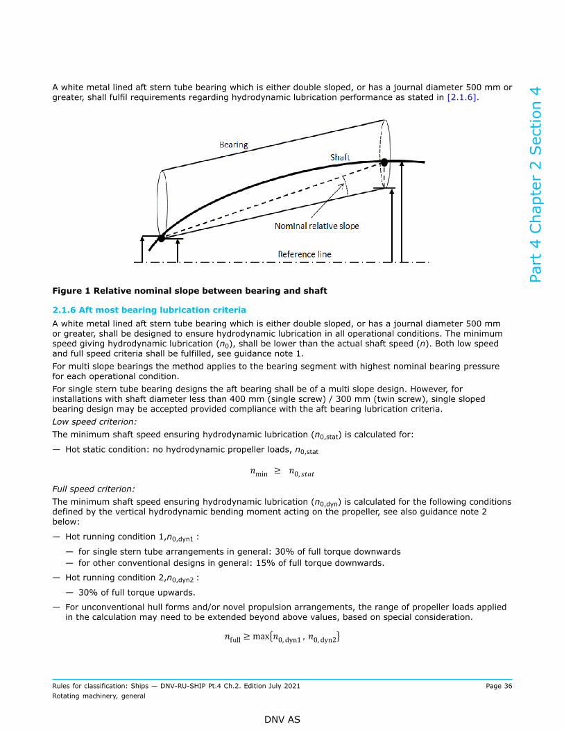
A white metal lined aft stern tube bearing which is either double sloped, or has a journal diameter 500 mm orgreater, shall fulfil requirements regarding hydrodynamic lubrication performance as stated in [2.1.6].
Figure 1 Relative nominal slope between bearing and shaft
2.1.6 Aft most bearing lubrication criteriaA white metal lined aft stern tube bearing which is either double sloped, or has a journal diameter 500 mmor greater, shall be designed to ensure hydrodynamic lubrication in all operational conditions. The minimumspeed giving hydrodynamic lubrication (n0), shall be lower than the actual shaft speed (n). Both low speedand full speed criteria shall be fulfilled, see guidance note 1.For multi slope bearings the method applies to the bearing segment with highest nominal bearing pressurefor each operational condition.For single stern tube bearing designs the aft bearing shall be of a multi slope design. However, forinstallations with shaft diameter less than 400 mm (single screw) / 300 mm (twin screw), single slopedbearing design may be accepted provided compliance with the aft bearing lubrication criteria.Low speed criterion:The minimum shaft speed ensuring hydrodynamic lubrication (n0,stat) is calculated for:
— Hot static condition: no hydrodynamic propeller loads, n0,stat
Full speed criterion:The minimum shaft speed ensuring hydrodynamic lubrication (n0,dyn) is calculated for the following conditionsdefined by the vertical hydrodynamic bending moment acting on the propeller, see also guidance note 2below:
— Hot running condition 1,n0,dyn1 :
— for single stern tube arrangements in general: 30% of full torque downwards— for other conventional designs in general: 15% of full torque downwards.
— Hot running condition 2,n0,dyn2 :
— 30% of full torque upwards.
— For unconventional hull forms and/or novel propulsion arrangements, the range of propeller loads appliedin the calculation may need to be extended beyond above values, based on special consideration.
Part 4 Chapter 2 Section 4
Rules for classification: Ships — DNV-RU-SHIP Pt.4 Ch.2. Edition July 2021 Page 36Rotating machinery, general
DNV AS
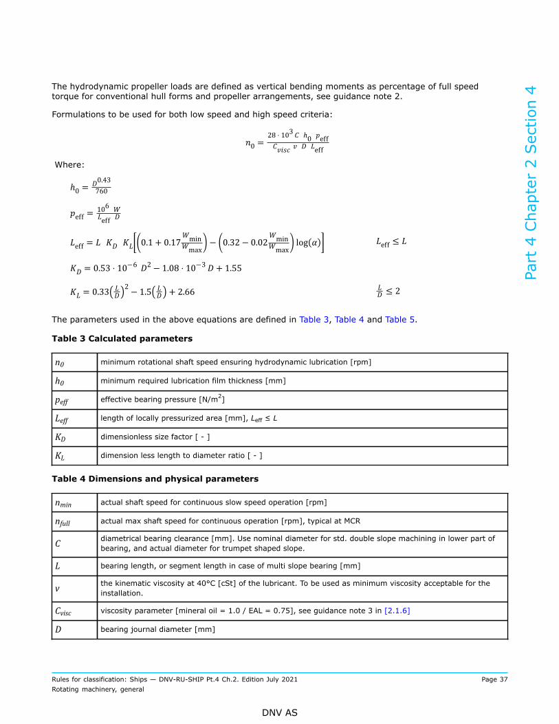
The hydrodynamic propeller loads are defined as vertical bending moments as percentage of full speedtorque for conventional hull forms and propeller arrangements, see guidance note 2.
Formulations to be used for both low speed and high speed criteria:
Where:
The parameters used in the above equations are defined in Table 3, Table 4 and Table 5.
Table 3 Calculated parameters
n0 minimum rotational shaft speed ensuring hydrodynamic lubrication [rpm]
h0 minimum required lubrication film thickness [mm]
peff effective bearing pressure [N/m2]
Leff length of locally pressurized area [mm], Leff ≤ L
KD dimensionless size factor [ - ]
KL dimension less length to diameter ratio [ - ]
Table 4 Dimensions and physical parameters
nmin actual shaft speed for continuous slow speed operation [rpm]
nfull actual max shaft speed for continuous operation [rpm], typical at MCR
C diametrical bearing clearance [mm]. Use nominal diameter for std. double slope machining in lower part ofbearing, and actual diameter for trumpet shaped slope.
L bearing length, or segment length in case of multi slope bearing [mm]
v the kinematic viscosity at 40°C [cSt] of the lubricant. To be used as minimum viscosity acceptable for theinstallation.
Cvisc viscosity parameter [mineral oil = 1.0 / EAL = 0.75], see guidance note 3 in [2.1.6]
D bearing journal diameter [mm]
Part 4 Chapter 2 Section 4
Rules for classification: Ships — DNV-RU-SHIP Pt.4 Ch.2. Edition July 2021 Page 37Rotating machinery, general
DNV AS
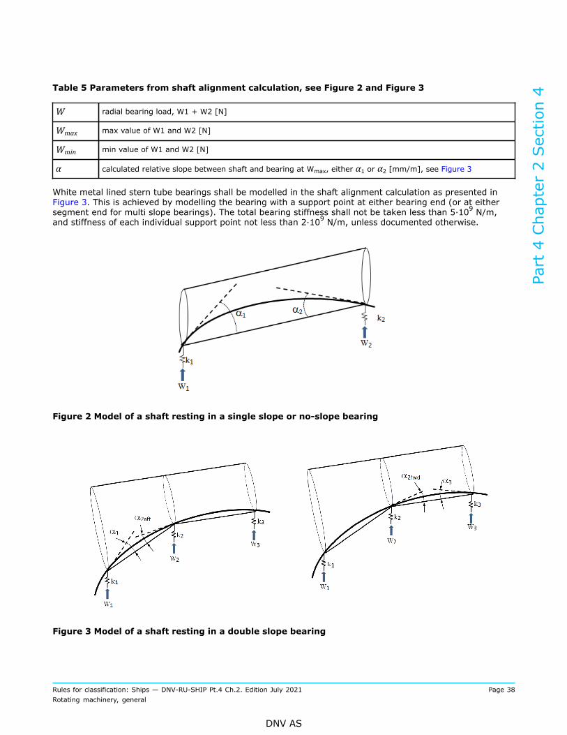
Table 5 Parameters from shaft alignment calculation, see Figure 2 and Figure 3
W radial bearing load, W1 + W2 [N]
Wmax max value of W1 and W2 [N]
Wmin min value of W1 and W2 [N]
α calculated relative slope between shaft and bearing at Wmax, either α1 or α2 [mm/m], see Figure 3
White metal lined stern tube bearings shall be modelled in the shaft alignment calculation as presented inFigure 3. This is achieved by modelling the bearing with a support point at either bearing end (or at eithersegment end for multi slope bearings). The total bearing stiffness shall not be taken less than 5·109 N/m,and stiffness of each individual support point not less than 2·109 N/m, unless documented otherwise.
Figure 2 Model of a shaft resting in a single slope or no-slope bearing
Figure 3 Model of a shaft resting in a double slope bearing
Part 4 Chapter 2 Section 4
Rules for classification: Ships — DNV-RU-SHIP Pt.4 Ch.2. Edition July 2021 Page 38Rotating machinery, general
DNV AS
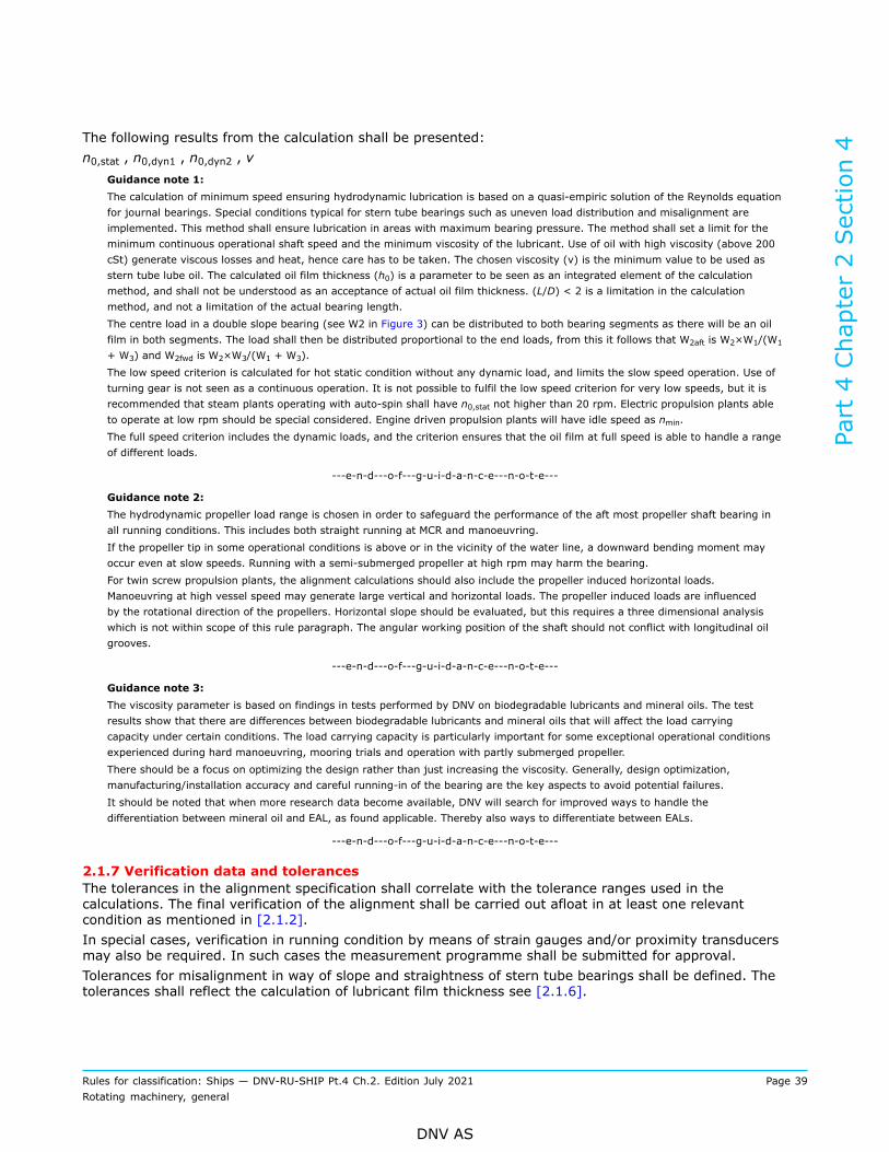
The following results from the calculation shall be presented:n0,stat , n0,dyn1 , n0,dyn2 , ν
Guidance note 1:The calculation of minimum speed ensuring hydrodynamic lubrication is based on a quasi-empiric solution of the Reynolds equationfor journal bearings. Special conditions typical for stern tube bearings such as uneven load distribution and misalignment areimplemented. This method shall ensure lubrication in areas with maximum bearing pressure. The method shall set a limit for theminimum continuous operational shaft speed and the minimum viscosity of the lubricant. Use of oil with high viscosity (above 200cSt) generate viscous losses and heat, hence care has to be taken. The chosen viscosity (ν) is the minimum value to be used asstern tube lube oil. The calculated oil film thickness (h0) is a parameter to be seen as an integrated element of the calculationmethod, and shall not be understood as an acceptance of actual oil film thickness. (L/D) < 2 is a limitation in the calculationmethod, and not a limitation of the actual bearing length.The centre load in a double slope bearing (see W2 in Figure 3) can be distributed to both bearing segments as there will be an oilfilm in both segments. The load shall then be distributed proportional to the end loads, from this it follows that W2aft is W2×W1/(W1
+ W3) and W2fwd is W2×W3/(W1 + W3).The low speed criterion is calculated for hot static condition without any dynamic load, and limits the slow speed operation. Use ofturning gear is not seen as a continuous operation. It is not possible to fulfil the low speed criterion for very low speeds, but it isrecommended that steam plants operating with auto-spin shall have n0,stat not higher than 20 rpm. Electric propulsion plants ableto operate at low rpm should be special considered. Engine driven propulsion plants will have idle speed as nmin.The full speed criterion includes the dynamic loads, and the criterion ensures that the oil film at full speed is able to handle a rangeof different loads.
---e-n-d---o-f---g-u-i-d-a-n-c-e---n-o-t-e---
Guidance note 2:The hydrodynamic propeller load range is chosen in order to safeguard the performance of the aft most propeller shaft bearing inall running conditions. This includes both straight running at MCR and manoeuvring.If the propeller tip in some operational conditions is above or in the vicinity of the water line, a downward bending moment mayoccur even at slow speeds. Running with a semi-submerged propeller at high rpm may harm the bearing.For twin screw propulsion plants, the alignment calculations should also include the propeller induced horizontal loads.Manoeuvring at high vessel speed may generate large vertical and horizontal loads. The propeller induced loads are influencedby the rotational direction of the propellers. Horizontal slope should be evaluated, but this requires a three dimensional analysiswhich is not within scope of this rule paragraph. The angular working position of the shaft should not conflict with longitudinal oilgrooves.
---e-n-d---o-f---g-u-i-d-a-n-c-e---n-o-t-e---
Guidance note 3:The viscosity parameter is based on findings in tests performed by DNV on biodegradable lubricants and mineral oils. The testresults show that there are differences between biodegradable lubricants and mineral oils that will affect the load carryingcapacity under certain conditions. The load carrying capacity is particularly important for some exceptional operational conditionsexperienced during hard manoeuvring, mooring trials and operation with partly submerged propeller.There should be a focus on optimizing the design rather than just increasing the viscosity. Generally, design optimization,manufacturing/installation accuracy and careful running-in of the bearing are the key aspects to avoid potential failures.It should be noted that when more research data become available, DNV will search for improved ways to handle thedifferentiation between mineral oil and EAL, as found applicable. Thereby also ways to differentiate between EALs.
---e-n-d---o-f---g-u-i-d-a-n-c-e---n-o-t-e---
2.1.7 Verification data and tolerancesThe tolerances in the alignment specification shall correlate with the tolerance ranges used in thecalculations. The final verification of the alignment shall be carried out afloat in at least one relevantcondition as mentioned in [2.1.2].In special cases, verification in running condition by means of strain gauges and/or proximity transducersmay also be required. In such cases the measurement programme shall be submitted for approval.Tolerances for misalignment in way of slope and straightness of stern tube bearings shall be defined. Thetolerances shall reflect the calculation of lubricant film thickness see [2.1.6].
Part 4 Chapter 2 Section 4
Rules for classification: Ships — DNV-RU-SHIP Pt.4 Ch.2. Edition July 2021 Page 39Rotating machinery, general
DNV AS
For single stern tube bearing designs the shaft alignment calculations shall consider the first inboard bearingload tolerance.
Guidance note:It is the designer's responsibility to ensure that relevant tolerances are provided in the shaft alignment report and/or specification.Such tolerances are closely related to the shafting system design and acceptance will be based on a complete evaluation of thedesign and calculations. The shaft alignment rules do not specify general requirements to tolerances, although the tolerancesshould be specified so that rule criteria are met within the tolerance ranges.The following tolerances will normally be acceptable unless the installation is very alignment sensitive or critical:
— Aftmost bearing slope: . For multi sloped bearings this applies to all bearing segments.
— If aftmost bearing slope is described by vertical offsets in each end of the bearing, the offset tolerance may be defined by the
following formula: .
— Gap and sag values: (see also [2.1.5]).
— Jack up loads: 20% of the design bearing load. Note that these default jack-up tolerances may need to be further limited. Suchlimitations may be due to:
— risk of exceeding maximum allowable bearing load
— risk of unloaded bearing
— large jack correction factors
— actual jack-up curve shows too large hysteresis or has a non-linear slope.
---e-n-d---o-f---g-u-i-d-a-n-c-e---n-o-t-e---
3 Installation
3.1 Inspection3.1.1 Work to be completed before inspectionAll large welding work in the vicinity of the shafting shall be completed before sighting process and insertionof propeller shaft. All large and heavy structure elements shall be in place before final verification of shaftalignment, see guidance note in [3.1.4].
3.1.2 Stern tube bearing validationWhen shaft alignment calculations are required (see [1.3.2]), the stern tube bearing geometry shall bemeasured and reported in presence of the surveyor after mounting of bearings, but prior to insertion ofthe propeller shaft. Straightness, slope and ovality shall be within the specified tolerances. Each stern tubebearing shall be checked at minimum three longitudinal positions covering the whole length of the bearing.Equal procedure shall be applied on each segment in case of multi slope bearing, see guidance note in[3.1.4].For single stern tube bearing designs, laser aided or similar sighting method of stern tube bearings shall beused. A minimum of two bearings shall be included in the sighting process.
3.1.3 Shaft alignment tolerancesThe shaft alignment shall be within the tolerances given in the shaft alignment specification, see guidancenote in [3.1.4].
3.1.4 Alignment verificationWhen shaft alignment calculations are required (see [1.3.2]), the measured values of gap and sag and/or jacking loads with force-displacement diagrams and/or alternative verification data shall be reported inpresence of the surveyor, see guidance note.
Part 4 Chapter 2 Section 4
Rules for classification: Ships — DNV-RU-SHIP Pt.4 Ch.2. Edition July 2021 Page 40Rotating machinery, general
DNV AS
Guidance note:Local effect verification: The designed geometry of stern tube bearings is based on the bearings ability to handle dynamic propellerloads and weight loads from propeller shaft and propeller. The condition inside stern tube bearings is dependent of accuracyboth in design and installation. It has to be verified that the bearing's slope(s), ovality and straightness are within the alignmentspecification with defined tolerances before propeller shaft is inserted. Global hull deflections should have limited influence to thealignment inside the stern tube, but welding in vicinity of the stern tube may disturb the alignment. Aftmost bearing mounted instruts should be evaluated case-by-case.Global effect verification: Mounting of large hull sections may introduce extra weight which should introduce global hull deflections.Large welding works and launching may also introduce hull deflections. Final verification of global shaft alignment such as gap andsag and/or jacking shall be carried out afloat with most of the hull completed.
---e-n-d---o-f---g-u-i-d-a-n-c-e---n-o-t-e---
For shafting installations not requiring approval, see [1.3.2], documentation of the installation of the shaftingin accordance with the alignment specifications shall be presented to the surveyor.
3.1.5 Stern tube lubricationPropeller shaft stern tube bearing lubricant type i.e. mineral oil/EAL, expected to be used in normal operationof the vessel shall be used during sea trials. Approved lubricant viscosity shall be confirmed during seatrials and documented. Suitable signboards shall be pasted at operating locations in machinery spaces andon the stern tube system tanks reflecting the minimum approved viscosity of the oil. The signboards shalldifferentiate between mineral oil and EAL.
Guidance note:Approved oil viscosity is included in the shaft alignment calculations for aft bearing lubrication criteria.
---e-n-d---o-f---g-u-i-d-a-n-c-e---n-o-t-e---
Part 4 Chapter 2 Section 4
Rules for classification: Ships — DNV-RU-SHIP Pt.4 Ch.2. Edition July 2021 Page 41Rotating machinery, general
DNV AS
SECTION 5 ELECTRIC POWER GENERATION
1 Prime mover driving electrical generators
1.1 Transient loadsEach prime mover used to drive main or emergency generator shall be fitted with a governor which shallprevent transient frequency variations in the electrical network in excess of ±10% of the rated frequencywith a recovery time to steady state conditions not exceeding five (5) seconds when the maximum electricalstep load is switched on or off.If a step load equivalent to the rated output of the generator is switched off, a transient speed variation inexcess of 10% of the rated speed may be acceptable, provided this does not cause the intervention of theoverspeed device as required by Ch.3 Sec.1 [5.3].
1.2 Detrimental speed variationAt all loads between no load and rated power, the permanent speed variation shall not deviate to a value thatmay be detrimental to the reliability of any electric consumer.
Guidance note:±5% of the rated speed is considered as a safe value.
---e-n-d---o-f---g-u-i-d-a-n-c-e---n-o-t-e---
1.3 Speed recoveryThe speed at the actual power after a load change shall be stabilized and in steady-state condition within fiveseconds, inside the permissible range for the permanent speed variation δr.The steady-state condition is considered reached when the permanent speed variation, δr, does not exceed ±1% of the speed associated with the set power.
1.4 Load demandPrime movers shall be selected in such a way that they shall meet the load demand within the ship’s mains.See Ch.3 Sec.1 [9.3.4] and Ch.3 Sec.1 [9.4] for load tests.
1.5 Two step on-loadingPrime movers driving electric generators, shall be able to accommodate sudden loading from no-load to 50%,followed by the remaining 50% of the rated generator power, duly observing requirements of [1.1] and [1.3].
1.6 Multistep on-loadingApplication of the load in more than two steps is acceptable on the condition that:
— the ship's electrical system is designed for the use of such generator sets— load application in more than two steps is considered in the design of the ship's electrical system and isapproved when the drawings are reviewed
— during shipboard trials the functional tests shall be carried out. Step loads caused by suddendisconnection of running generators shall be tested, and it shall be verified that the main source of electricpower is maintained at all time.
Part 4 Chapter 2 Section 5
Rules for classification: Ships — DNV-RU-SHIP Pt.4 Ch.2. Edition July 2021 Page 42Rotating machinery, general
DNV AS
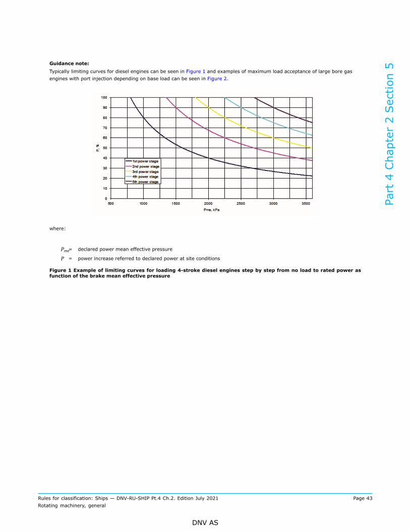
Guidance note:Typically limiting curves for diesel engines can be seen in Figure 1 and examples of maximum load acceptance of large bore gasengines with port injection depending on base load can be seen in Figure 2.
where:
Pme= declared power mean effective pressure
P = power increase referred to declared power at site conditions
Figure 1 Example of limiting curves for loading 4-stroke diesel engines step by step from no load to rated power asfunction of the brake mean effective pressure
Part 4 Chapter 2 Section 5
Rules for classification: Ships — DNV-RU-SHIP Pt.4 Ch.2. Edition July 2021 Page 43Rotating machinery, general
DNV AS
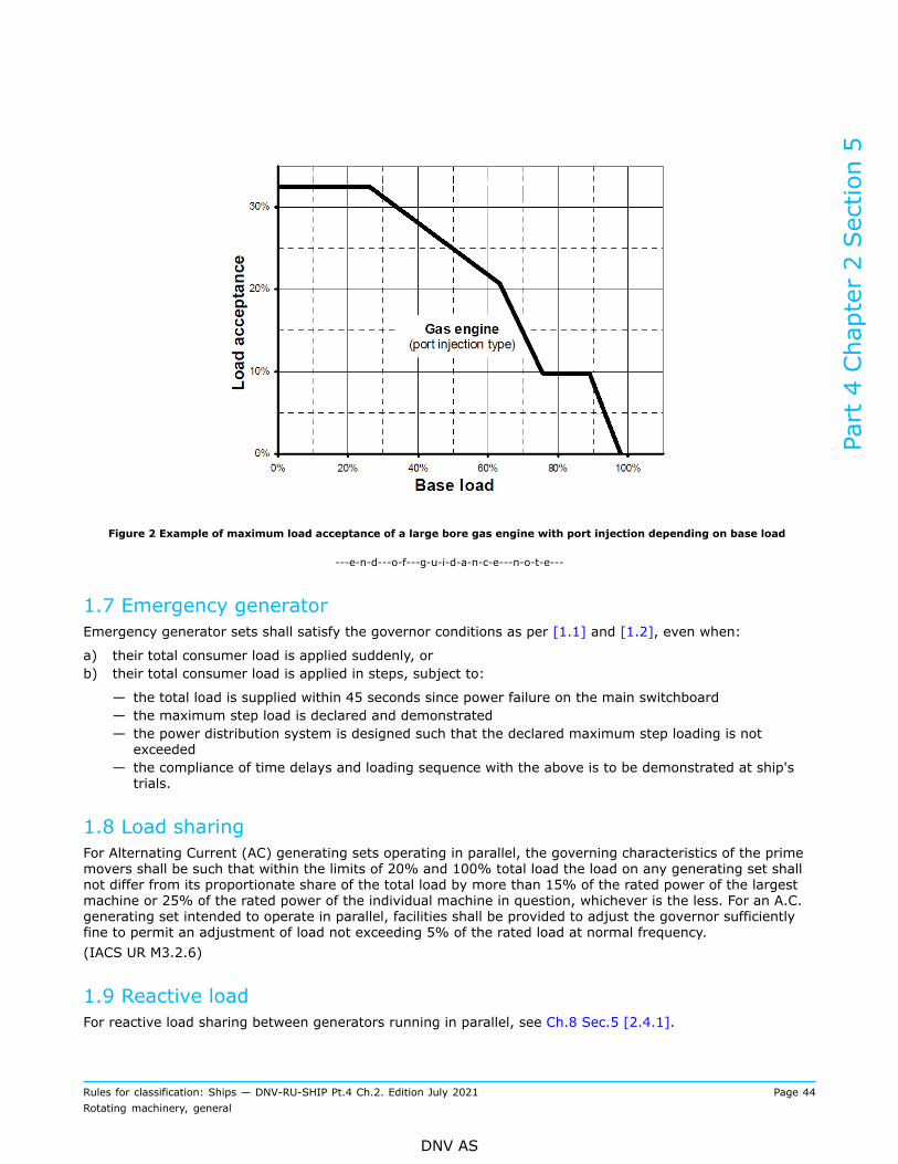
Figure 2 Example of maximum load acceptance of a large bore gas engine with port injection depending on base load
---e-n-d---o-f---g-u-i-d-a-n-c-e---n-o-t-e---
1.7 Emergency generatorEmergency generator sets shall satisfy the governor conditions as per [1.1] and [1.2], even when:
a) their total consumer load is applied suddenly, orb) their total consumer load is applied in steps, subject to:
— the total load is supplied within 45 seconds since power failure on the main switchboard— the maximum step load is declared and demonstrated— the power distribution system is designed such that the declared maximum step loading is notexceeded
— the compliance of time delays and loading sequence with the above is to be demonstrated at ship'strials.
1.8 Load sharingFor Alternating Current (AC) generating sets operating in parallel, the governing characteristics of the primemovers shall be such that within the limits of 20% and 100% total load the load on any generating set shallnot differ from its proportionate share of the total load by more than 15% of the rated power of the largestmachine or 25% of the rated power of the individual machine in question, whichever is the less. For an A.C.generating set intended to operate in parallel, facilities shall be provided to adjust the governor sufficientlyfine to permit an adjustment of load not exceeding 5% of the rated load at normal frequency.(IACS UR M3.2.6)
1.9 Reactive loadFor reactive load sharing between generators running in parallel, see Ch.8 Sec.5 [2.4.1].
Part 4 Chapter 2 Section 5
Rules for classification: Ships — DNV-RU-SHIP Pt.4 Ch.2. Edition July 2021 Page 44Rotating machinery, general
DNV AS
1.10 Rated speed adjustmentThe governors of the engines shall enable the rated speed to be adjusted over the entire power range with amaximum deviation of 5%.
1.11 SynchronizationThe rate of speed variation of the adjusting mechanisms shall permit satisfactory synchronization in a shorttime.
Guidance note:Relating to Ch.3 Sec.1 [5.2.1] and [1]:The rated power and the corresponding rated speed relate to the conditions under which the engines are operated in the systemconcerned.
---e-n-d---o-f---g-u-i-d-a-n-c-e---n-o-t-e---
1.12 Electric power supply systemFor further requirements related to main electric power supply system including the use of shaft generator,see Ch.8 Sec.2 [2] and for emergency power supply system, see Ch.8 Sec.2 [3].
1.13 Marking of AC generating setsAll generator sets shall be marked as listed in DNV-CG-0565 Sec.2 [1.4].
Part 4 Chapter 2 Section 5
Rules for classification: Ships — DNV-RU-SHIP Pt.4 Ch.2. Edition July 2021 Page 45Rotating machinery, general
DNV AS
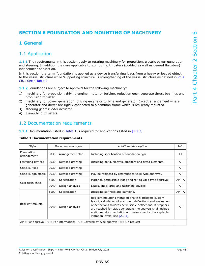
SECTION 6 FOUNDATION AND MOUNTING OF MACHINERY
1 General
1.1 Application
1.1.1 The requirements in this section apply to rotating machinery for propulsion, electric power generationand steering. In addition they are applicable to azimuthing thrusters (podded as well as geared thrusters)independent of function.In this section the term 'foundation' is applied as a device transferring loads from a heavy or loaded objectto the vessel structure while 'supporting structure' is strengthening of the vessel structure as defined in Pt.3Ch.1 Sec.4 Table 7.
1.1.2 Foundations are subject to approval for the following machinery:
1) machinery for propulsion: driving engine, motor or turbine, reduction gear, separate thrust bearings andpropulsion thruster
2) machinery for power generation: driving engine or turbine and generator. Except arrangement wheregenerator and driver are rigidly connected to a common frame which is resiliently mounted
3) steering gear: rudder actuator4) azimuthing thrusters.
1.2 Documentation requirements
1.2.1 Documentation listed in Table 1 is required for applications listed in [1.1.2].
Table 1 Documentation requirements
Object Documentation type Additional description Info
Foundationarrangement Z030 – Arrangement plan Including specification of foundation type. FI
Fastening devices C030 – Detailed drawing Including bolts, sleeves, stoppers and fitted elements. AP
Chocks, fixed C030 – Detailed drawing AP
Chocks, adjustable C030 – Detailed drawing May be replaced by reference to valid type approval. AP
Z100 – Specification Material, permissible loads and ref. to valid type approval. AP, TACast resin chock
C040 – Design analysis Loads, chock area and fastening devices. AP
Z100 – Specification Including stiffness and damping. AP, TA
Resilient mountsC040 – Design analysis
Resilient mounting vibration analysis including systemlayout, calculation of maximum deflections and evaluationof deflections towards permissible deflections. If stoppersare reached for static conditions the analysis shall includeadditional documentation or measurements of acceptablevibration levels, see [2.3.3].
AP
AP = For approval; FI = For information; TA = Covered by type approval; R= On request
Part 4 Chapter 2 Section 6
Rules for classification: Ships — DNV-RU-SHIP Pt.4 Ch.2. Edition July 2021 Page 46Rotating machinery, general
DNV AS
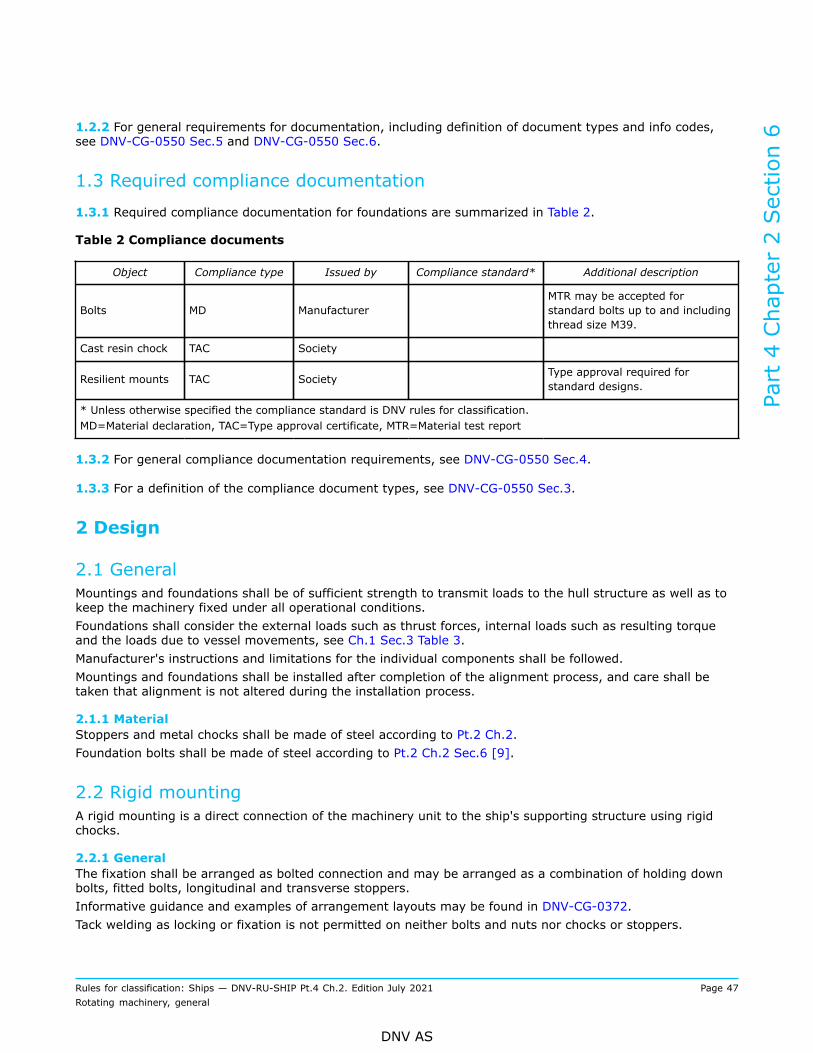
1.2.2 For general requirements for documentation, including definition of document types and info codes,see DNV-CG-0550 Sec.5 and DNV-CG-0550 Sec.6.
1.3 Required compliance documentation
1.3.1 Required compliance documentation for foundations are summarized in Table 2.
Table 2 Compliance documents
Object Compliance type Issued by Compliance standard* Additional description
Bolts MD ManufacturerMTR may be accepted forstandard bolts up to and includingthread size M39.
Cast resin chock TAC Society
Resilient mounts TAC Society Type approval required forstandard designs.
* Unless otherwise specified the compliance standard is DNV rules for classification.MD=Material declaration, TAC=Type approval certificate, MTR=Material test report
1.3.2 For general compliance documentation requirements, see DNV-CG-0550 Sec.4.
1.3.3 For a definition of the compliance document types, see DNV-CG-0550 Sec.3.
2 Design
2.1 GeneralMountings and foundations shall be of sufficient strength to transmit loads to the hull structure as well as tokeep the machinery fixed under all operational conditions.Foundations shall consider the external loads such as thrust forces, internal loads such as resulting torqueand the loads due to vessel movements, see Ch.1 Sec.3 Table 3.Manufacturer's instructions and limitations for the individual components shall be followed.Mountings and foundations shall be installed after completion of the alignment process, and care shall betaken that alignment is not altered during the installation process.
2.1.1 MaterialStoppers and metal chocks shall be made of steel according to Pt.2 Ch.2.Foundation bolts shall be made of steel according to Pt.2 Ch.2 Sec.6 [9].
2.2 Rigid mountingA rigid mounting is a direct connection of the machinery unit to the ship's supporting structure using rigidchocks.
2.2.1 GeneralThe fixation shall be arranged as bolted connection and may be arranged as a combination of holding downbolts, fitted bolts, longitudinal and transverse stoppers.Informative guidance and examples of arrangement layouts may be found in DNV-CG-0372.Tack welding as locking or fixation is not permitted on neither bolts and nuts nor chocks or stoppers.
Part 4 Chapter 2 Section 6
Rules for classification: Ships — DNV-RU-SHIP Pt.4 Ch.2. Edition July 2021 Page 47Rotating machinery, general
DNV AS
Foundation shall be arranged with easy access and inspection openings for maintenance activities andchecking of pre-tension in foundation bolts.Innovative or unconventional type of foundation will be subject to special consideration.
2.2.2 Foundation bolts
2.2.2.1 Holding down boltsHolding down bolts are bolts which take load in vertical direction, and by pre-tension and friction enable thebolted connection to take load in transverse and longitudinal direction.Bolts shall have sufficient pre-tension to prevent relative movement between machinery and chocks due todynamic load. Pre-tension should at least be 70% of yield strength. Additionally the holding down bolts shallhave sufficient elongation to maintain the pretension for the occurring load variation.
Guidance note:Following values of elongations are recommended unless otherwise is substantiated:
— 0.25 mm for mountings on metal chocks
— according to DNV-CG-0372 Sec.3 [2] for mounting on cast resin chocks. Additionally, possible creep of resin over time shall betaken into consideration.
---e-n-d---o-f---g-u-i-d-a-n-c-e---n-o-t-e---
2.2.2.2 Fitted boltsFoundation bolts are bolts mounted with a press fit and provide shear capacity to the bolted connectiontowards loads in longitudinal or transverse direction.Fitted bolts may be applied as alternative to stoppers. Bolts shall then have shear capacity equivalent to whatis required of stoppers.
2.2.2.3 Locking of boltsThe nuts for the foundation bolts shall be secured with locking nuts or equivalent solutions.
2.2.3 StoppersStoppers are fixed supports in longitudinal direction (end and front stoppers) or transverse direction (sidestoppers).Stoppers are required for all equipment exposed to external loads (such as thrust forces) and shall havecapacity to carry the external load independently from friction capacity in foundation bolts.Wedged or double wedged chocks shall be used between the stoppers and machinery bedplate. Wedges shallbe secured by welding the entire wedge length. Use of shims is not permitted.
2.2.4 Metal chocksMetal chocks in this context are considered the chocks used for vertical adjustment between the machinerybedplate and the supporting structure.Chocks shall be made of steel or cast iron and should have a minimum thickness of 20 mm. Use of shims isnot permitted, however a combination of up to 3 chocks may be accepted.The mating surfaces of steel chocks, bedplate and supporting structure landing surfaces shall be machined tohave good contact.
2.2.5 Cast resin chocksCast resin chocks in this context are considered the chocks used for vertical adjustment between themachinery bedplate and the supporting structure.Resin casting compounds shall be type approved according to DNV-CP-0432 Sec.1 Type approval according toEU RO Mutual Recognition Technical Requirements for Resin Chock may be accepted. Boundary conditions forpermissible loads and casting process shall be complied with.The height of resin chock should be in the range of 20 mm - 50 mm. Acceptance of chock heights outside thisrange will be pending on resin manufacturer's acceptance.
Part 4 Chapter 2 Section 6
Rules for classification: Ships — DNV-RU-SHIP Pt.4 Ch.2. Edition July 2021 Page 48Rotating machinery, general
DNV AS
2.2.6 Machinery component specific requirementsRequirements in [2.2.6] apply in addition to requirements in [2.2.1] to [2.2.5].
2.2.6.1 Reciprocating combustion enginesReciprocating engines are subject to vibratory forces in addition to the result torque, and in case of directcoupled propulsion plant, thrust forces.Foundation bolts for reciprocating engines shall have elongation according to [2.2.2.1].Engine foundation shall be arranged with front and end stoppers as well as side stoppers. Engines with morethan 6 cylinders in one line and a cylinder diameter ≥ 250 mm shall have an additional pair of stoppers intransverse direction located near the midpoint of engine length, close to a bearing stool.Arrangement with fitted bolts instead of stoppers may be accepted provided engine manufacturer'sacceptance.Top stays shall be fastened to a supporting hull structure with stiffness and strength dimensioned for themaximum transmittable load.
2.2.6.2 Gas turbines and steam turbinesTurbines shall be provided with end stoppers and side stoppers.Gas turbines supports (struts) shall have a safety factor of 2.5 towards buckling.
2.2.6.3 Gear transmissionsGear transmissions exposed to external forces such as thrust forces shall be provided with longitudinalstoppers. Arrangement with fitted bolts instead of stoppers may be accepted provided manufacturer'sacceptance.
2.2.6.4 Separate thrust bearingsThrust bearings shall be provided with stoppers in longitudinal direction.
2.2.6.5 Steering gearsSteering gears with integrated bearings are subject to axial and radial load as well as torque from steeringgear.The foundation arrangement shall be capable of transmitting the higher of 2 times rule rudder torque and 1.5times design torque delivered from steering gear.Steering gears mounted on resin chocks shall be arranged with stoppers. Arrangements with fitted boltsinstead of stoppers may be accepted provided manufacturer's acceptance, and an evaluation of stresses,including the additional bending stresses due to deflection of resin.Cast resin chocks supporting steering gear with integrated bearings shall be dimensioned to carry the weightof rudder and rudder stock in addition to the steering gear.
2.3 Resilient mounting2.3.1 GeneralA resilient mounting is a connection between machinery unit and the ship's supporting structure using elasticmounting components.The arrangement of flexible pipes and hoses shall allow maximum movements of the engine and minimisethe strain on the hoses, see also DNV-CG-0372 App.A Figure 24.Resilient mounts shall be type approved according to DNV-CP-0144.
2.3.2 Natural frequenciesResilient mountings of high speed and medium speed diesel engines are primarily used in order to reduceshock loads and reduce the transmission of vibrations and structure-borne sound into the ship's hull. Toachieve the desired insulation effect the natural frequencies of the resilient mounting shall be sufficientlyseparated from the dominating excitation frequencies.
Part 4 Chapter 2 Section 6
Rules for classification: Ships — DNV-RU-SHIP Pt.4 Ch.2. Edition July 2021 Page 49Rotating machinery, general
DNV AS
For ships, calculated natural frequencies and the excitation frequencies shall be separated by 20%.For high speed crafts and light crafts (HS, LC and NSC), calculated natural frequencies and the excitationfrequencies shall be separated by 30%.Arrangements where the separation limits above are not complied with may be accepted provided a forcedresponse calculation or vibration measurements showing acceptable results according to specific componentmanufacturers's recommendation.
Guidance note:1st order shaft rotating frequency may be considered as the main dominating frequency for normal operation, and in addition 0.5th
and 1.5th order for misfiring condition.
---e-n-d---o-f---g-u-i-d-a-n-c-e---n-o-t-e---
2.3.3 LoadsThe resilient mounts shall support the machinery system for all the following loads acting simultaneously,without exceeding the permissible values neither for the mounts nor the other components or connections inthe system:
— mass of the engine— reaction forces due to engine torque— maximum environmental conditions, see Ch.1 Sec.3 Table 3.
Resilient mounts should be arranged with even load distributions and deflections of the mounts. Unevenloading of mounts to compensate for tilting due to operation loads may be accepted.Excessive movements shall be prevented either by dual characteristic mounts or by stoppers. Excessivemovements are movements beyond those expected under normal running conditions and environmentalconditions specified in Ch.1 Sec.3 Table 3.For dual characteristics mounts the second stiffness level may be utilized if this is included in the model andforeseen in the analysis.If stoppers are reached during static loading conditions specified in environmental conditions in Ch.1Sec.3 Table 3, by default 15 degrees list or 5 degrees trim, the arrangement may be accepted providedan additional analysis (e.g. time domain vibration analysis) or measurements with stopper contact showacceptable vibration levels on engine and critical components.
Guidance note:Transient conditions with stopper contact due to dynamic ship movement are not considered critical.
---e-n-d---o-f---g-u-i-d-a-n-c-e---n-o-t-e---
2.3.4 Resilient mount vibration analysisThe analysis shall document that design requirements and limitations are complied with. The positions of theengine on the elastic mounts shall be calculated under consideration of the loads given in [2.3.3].
2.3.4.1 Uncertainty in parametersVariation of essential data such as dynamic characteristics of rubber elements shall be considered andpresented. Fabricated rubber may have tolerances of stiffness and damping, and may vary with regards toe.g. temperature.
2.3.4.2 Source of dataThe source of all essential data shall be listed in the vibration calculation report. For data that cannot begiven as constant parameters, the assumed parameter dependency and tolerance range shall be specified.
2.3.4.3 Report contentReports shall as a minimum contain the following:
— description of the complete spring-mass system— arrangement, number and securing measures for the resilient mounting components, vibration amplitudelimiters, and, where appropriate, locking devices
Part 4 Chapter 2 Section 6
Rules for classification: Ships — DNV-RU-SHIP Pt.4 Ch.2. Edition July 2021 Page 50Rotating machinery, general
DNV AS
— specification of data for the resilient mounting components:
— manufacturer— designation, type, dimensions, shore hardness— spring stiffness for the horizontal and vertical loading directions (static and dynamic)— damping coefficients— characteristic curves for the horizontal and vertical load direction with details concerning permissiblecontinuous load
— data concerning the time settling behaviour at ambient conditions, see Ch.1 Sec.3 Table 3.
— specification of data for the torsionally flexible coupling as well as for the essential flexible pipeconnections
— calculation of the natural frequencies of the total vibrational system for 6 degrees of freedom (x, y, z, dx,dy, dz), see definitions in Pt.3 Ch.1 Sec.4 [3.6]
— calculation of the displacements in the x, y, and z directions at the flexible system components, based onthe loads in [2.3.3]
— conclusion comparing calculated response and the permissible values for all the sensitive parts in theplant. Assumptions, conditions and restrictions shall be presented.
3 Installation survey
3.1 InstallationFoundations for machinery for propulsion, power generation and steering are subject to survey by theSociety.
3.1.1 Foundation boltsA work report of applied pre-tensioning of foundation bolts shall be presented to the Society upon request.
3.1.2 Metal chockClearances of metal chocks shall be less than 0.1 mm prior to bolt tightening.
3.1.3 Resin chockResin chocks shall be cast in the presence of the Society.
3.1.4 Resilient mountingAdjustment of the resilient mounts and stopper distances shall be performed in the presence of the Society.
4 Shipboard testing
4.1 Resilient mountingThe movement of resiliently mounted machinery shall be observed, with focus on full load and enginemisfiring condition. The stoppers or limiters of the resilient mounts shall not be reached. None of theconnections shall restrict the movement of the machinery, such as exhaust bellow, cooling water orlubrication pipe.
Part 4 Chapter 2 Section 6
Rules for classification: Ships — DNV-RU-SHIP Pt.4 Ch.2. Edition July 2021 Page 51Rotating machinery, general
DNV AS
CHANGES – HISTORIC
July 2020 edition
Changes July 2020, entering into force 1 January 2021Only editorial corrections have been made.
July 2019 edition
Changes July 2019, entering into force 1 January 2020Topic Reference Description
Alignment with IACS URM3 rev6 (Nov 2018)
Sec.5 Figure 1 Updated guidance note.
Improvement of requirementsfor foundation and mounting ofrotating machinery
Sec.6 New section replacing high level requirements from Sec.1[6](now deleted).
The requirements on foundation and mounting rotatingmachinery have been expanded to describing function andrequirements for the individual foundation elements and forfixation. In addition engine vibration calculation has beenadded.
Sec.4 [2.1.6] Introduced viscosity parameter differentiating between EAL andmineral oils.Added guidance note to explain the reasoning for theparameter.
Updated requirement on minimum oil viscosity for signboard.
Sec.6 [1.1.2] Foundation of generator set mounted on common frame isexempted from approval.
Sec.6 Table 2 Requirements on material certificate for bolts are reduced totest report for bolt size up to M39, and maker's certificate forlarger bolts.
Sec.6 [2.1.1] Added requirement for materials, with reference to Pt.2.
Differentiation between EALand mineral oil for shaftalignment/stern tube bearing
Sec.6 [2.3] Clarified load conditions and acceptance criteria for resilientmount.Clarified content of required calculations and analysis.
July 2018 edition
Changes July 2018, entering into force 1 January 2019Topic Reference Description of change
Barred speed range andfatigue of main shafting
Sec.2 [1.2] New symbol: tBSR.New definitions: Barred speed range, Power margin at BSR.
Part 4 Chapter 2 Changes – historic
Rules for classification: Ships — DNV-RU-SHIP Pt.4 Ch.2. Edition July 2021 Page 52Rotating machinery, general
DNV AS
Topic Reference Description of change
Sec.2 Table 4 New footnote ***) related to reduced requirements for poddedthrusters: forced vibration calculation not required if lowestnatural frequency is above 2nd blade order propeller excitation.Free vibration calculation to be presented.
Sec.2 [2.3.2] If propeller excitation is used as active damping for engineexcitations, it will require a specific CFD for the actual project,alternatively use 50% the table values.
Sec.2 [2.3] Presentation of results is revised and extended for case wherebarred speed range is specified. Maximum time shall be withinacceptance criteria and power margin with associated curvesshall be presented.
Sec.2 [2.4.3.2] Added guidance note in order to be compliant with new Balticice class rules.
Sec.2 [2.4] Passing through a barred speed range is removed from Sec.2[2.4.3].
Sec.2 [2.5.3] New: Sec.2 [2.5.3] time for passing barred speed range.Formula for allowable time passing barred speed range (tBSR)with explanation of input values. Extensive guidance noteexplaining background for formula as it is not self-explanatory.
Sec.2 [2.5.4] New: Sec.2 [2.5.4] with acceptance criterion for power margin,which shall be larger or equal to 10%, unless supported byexperience and/or extended analysis.
Sec.2 [2.5.11] Limits for gear hammer in unloaded PTO-branches areincreased: 10-->20% (normal), 15-->25% (misfiring).
Sec.2 [3] Sec.2 [3.1] revised.Previous Sec.2 [3.1.1] is split into Sec.2 [3.1.1] and Sec.2[3.1.2] and revised.
Parameters to measure and parameters to register are movedto Sec.2 [4.2.3] and Sec.2 [4.2.4].
Sec.2 [3.1.5]: new paragraph related to misfire.
Sec.2 [3.1.7]: new paragraph related to alarm if time passingbarred speed range exceeds approved value.
Sec.2 [4] New Sec.2 [4.2] with 6 paragraphs related to measurements ofbarred speed range.
Rule text editorial Sec.2 [1] Sec.2 [1.1.5]: time domain calculation changed fromalternative to additional upon request.Sec.2 [1.4]: document requirements open up for free vibrationcalculation only for pods with high natural frequencies.
Part 4 Chapter 2 Changes – historic
Rules for classification: Ships — DNV-RU-SHIP Pt.4 Ch.2. Edition July 2021 Page 53Rotating machinery, general
DNV AS
January 2018 edition
Changes January 2018, entering into force 1 July 2018Topic Reference Description
Sec.4 [1.1.1] Clarification that only fully submerged propellers are covered by theclass rules.
Sec.4 [1.1.3] Single stern tube bearings requiring alignment calculation shall fulfil thelubrication criteria of [2.1.6].
Update of shaftalignment rules.
Sec.4 [2.1.6] Lubrication criteria: Added requirement for single stern tube bearingsto be of multi slope design, and increasing the hydrodynamic bendingmoment downward to 30%, while reducing the upward bending momentfrom 40% to 30% for al arrangements.
July 2016 edition
Amendment January 2017
• Sec.1 Introduction— Sec.1 [6.1.5]: New paragraph added regarding resilient mounting.
Main changes July 2016, entering into force 1 January 2017
• Sec.2 Torsional vibrations— Sec.2 [2.3.1]: A new guidance note has been included regarding inertia of entrained water.
• Sec.4 Shaft alignment— Sec.4 [2.1.4]: Procedure from shaft alignment calculation shall include description of method and bepossible to re-use when in service.
• Sec.5 Electric power generation— Sec.5 [1.4]: A reference to Pt.4 Ch.3 for applicable load tests has been included.
January 2016 editionThis document supersedes the October 2015 edition.
Main changes January 2016, entering into force 1 July 2016
• Sec.2 Torsional vibrations— Table 4: Added documentation requirement fatigue calculation for conventional propulsion arrangement.— [2.3.1]: Where barred speed range is required, maximum time for passing shall be specified.
Part 4 Chapter 2 Changes – historic
Rules for classification: Ships — DNV-RU-SHIP Pt.4 Ch.2. Edition July 2021 Page 54Rotating machinery, general
DNV AS
— [2.5.4]: Extended documentation to be submitted where it is likely to expect high cycle fatigue due topassing of barred speed range including new guidance note.
— [3]: Requirements for check of barred speed range have been updated to align with new IACS UR M51[4.5].
October 2015 edition
GeneralThis is a new document.The rules enter into force 1 January 2016.
Part 4 Chapter 2 Changes – historic
Rules for classification: Ships — DNV-RU-SHIP Pt.4 Ch.2. Edition July 2021 Page 55Rotating machinery, general
DNV AS
About DNVDNV is the independent expert in risk management and assurance, operating in more than 100countries. Through its broad experience and deep expertise DNV advances safety and sustainableperformance, sets industry benchmarks, and inspires and invents solutions.
Whether assessing a new ship design, optimizing the performance of a wind farm, analyzing sensordata from a gas pipeline or certifying a food company’s supply chain, DNV enables its customers andtheir stakeholders to make critical decisions with confidence.
Driven by its purpose, to safeguard life, property, and the environment, DNV helps tackle thechallenges and global transformations facing its customers and the world today and is a trustedvoice for many of the world’s most successful and forward-thinking companies.
WHEN TRUST MATTERS