Embed Size (px)
Citation preview

Ulmer Informatik Berichte | Universität Ulm | Fakultät für Ingenieurwissenschaften, Informatik und Psychologie
Rule-based Monitoring Framework for Business Process Compliance
Ping Gong, David Knuplesch, and Manfred Reichert
Ulmer Informatik-Berichte Nr. 2016-03
März 2016

Rule-based Monitoring Framework for BusinessProcess Compliance
Ping Gong1?, David Knuplesch2, and Manfred Reichert2
1 Department of Computer ScienceFujian Normal University
Fuzhou 350007, P. R. [email protected]
2 Institute of Databases and Information Systems,Ulm University, Germany
{david.knuplesch,manfred.reichert}@uni-ulm.de
Abstract. Business processes compliance monitoring can be viewed as the taskof detecting and reacting to the compliance of running business processes withcompliance rules, which are the semantic constraints originated from norms,standards, and laws, etc. Normally, compliance rules not only refer to normalprocess perspectives, like control flow, data flow, and time, but also perspec-tives of data aggregation as well as their mixtures. Such characteristics as wellas potentially high number of concurrently running process instances, post chal-lenges for processes compliance monitoring from the aspects of specification andmonitoring efficiency. In this work, we address these challenges by proposing acompliance monitoring framework (bpCMon), which includes an event-basedcompliance language (ECL) and event reaction system (ERS). More specifi-cally, ECL is a formal language enabling specifying compliance rules of multi-perspective. ERS is a powerful rule-based system enriched with events indexingstructure, and fully supports the monitoring for compliance rules in ECL. Ex-periments on a real life datasets indicate the applicability of bpCMon; and thecomparisons with three related works over benchmarks demonstrate the effi-ciency of bpCMon.
Keywords: Business process compliance monitoring, runtime verification
1 Introduction
Business process compliance (BPC) essentially means that business processes are ex-ecuted in conformance with prescribed and agreed sets of compliance rules [1]. BPCcan be ensured and verified at different phases of process life cycle, e.g., a priori atdesign time or a posteriori based on logs of completed processes. However, in realisticsetting, the deviation of actual running from the process definition and the potentialimplicitness of process definition, highlight the necessary of compliance monitoring forBPC.
Compliance monitoring is the task of detecting and reacting to the compliance vi-olations of running business processes based on the monitoring mechanism, which isgenerated from prescribed compliance rule. Lion’s share of compliance monitoring re-search has been focusing on compliance rule language and monitoring mechanism. As
? The work was finished during the author visited Ulm univeristy.
2 Ping Gong, David Knuplesch, and Manfred Reichert
Running Examples
Fraud Prevention: Following compliance rules address the prevention of frauds in thebanking domain and source from [10, 14]:B1. Every executed transferring transaction of customer, who has within the last 30days been involved in a suspicious transaction (transferring with amount greater than10,000e), must be reported suspicious within 2 days.B2. The sum of withdraws of each user over the last 30 days does not exceed the limitof 10,000e.B3. For each user, the number of withdrawing peaks over the last 30 days does notexceed a threshold of 5, where a peak is a value at least twice the average over sometime window(30 days).
BPIC 2011: The Business Process Intelligence 2011 Contest (BPIC 2011) logs3 are real
life datasets stemmed from a Dutch hospital and are provided in XES format [22]. In [20],
16 rules referring to various process perspectives were mined from these logs by using De-
clare Miner tool. Out of these 16 rules, following R9 and R11 are listed as examples:
R9. If “administratief tarief -eerste pol” occurs in a trace, it is always preceded by “ver-
volgconsult poliklinisch” and it occurs at most 1030 days before “administratief tarief
-eerste pol”.
R11. If “natrium vlamfortometrisch” occurs in a trace and the condition “(Age≥71 &&
Treatment code ≥ 803&& Diagnosis Treatment Combination ID≤ 394,725) ‖ (Treatment
code==703 ‖ Treatment code ==803))” holds, then “natrium valmfotometrisch” is not
followed eventually by “calcium”.
opposed to a priori compliance checking, compliance monitoring does not require to ex-plore the whole state space of process model, and also enable handling the running dataof process in real-time manner. These characteristics make compliance monitoring tobe promising techniques which enable providing business practitioners with meaningfuland timely insights into their running processes.
Usually, the compliance requirements are sourced from norms, guidelines, and stan-dards. Additinal effort is needed to refine them operable through relevance methods,e.g., semantic parameterization [3]. In this work, the term of compliance rule refers tothe constraints which are yielded after compliance requirement refinement. Normally,compliance rules refer to different process perspectives, including activity, control flow,data flow, time, and resource as well as data aggregation. These perspectives are notsimply co-existed, but related each orther to associate with single activity or correlatedamong activities. This characteristic poses further requirements for compliance moni-toring:
More dedicated language is needed. Existing compliance languages [4–9] aredesigned base on the notions of activity and control flow. However, regarding to abovementioned characteristic, more dedicated constructs of compliance language are neededto specify the structure of activity as well as the correlations among activities. TakingR11 as an example, besides the control flow between two involved activities, the firstactivity also includes complicated data constraints, which implies the need for proper

Rule-based Monitoring Framework for Business Process Compliance 3
CRM System
Web Services
…
ECL
ECL
Peoples
BPM system
Compliance rules Compliance Monitors
events
Inner view ERS monitor
Rule System
Working Structure
#g() #w() #d() …
ERS monitor
translate
bpCMon
ERS monitor
Fig. 1. The applying environment for bpCMon and the inner strucutre of ERS monitor
construct to describe desired activity. Also considering B1, in addition to the apparentcontrol flow and time constraints among transferring and report, there also exist twodata correlations among these activities, i.e., one transferring is correlated by the sameuser to another suspicious transferring happened before, and also such transferring iscorrelated to report by given attribute, e.g., transactionID. Note that, without spec-ifying these correlations, the complance rules would not be correctly specified, whichwould further result in false reports during compliance monitoring. Furthermore, B2and B3, referring to the aggregations of withdraw amount over time periods, e.g., sum,max, and average, highlight the need for additional constructs to support data aggre-gation.
Powerful and efficient monitoring mechanism is required, to cope with com-plex compliance rules and potentially high volume of running process instances. Exist-ing monitoring techniques, e.g., temporal logic based [12–14], event calculus based [15],state-machine/marking based [16, 8, 9], rule sytem based [21], etc, have their own prosand cons. Considering the potential power and extensibility of underlying formalisms,as stated in [21], rule system based techniques have the potential of by the uniformformalism enabling to support compliance rules of full perspectives, especially data ag-gregation. However, as implied in the experiments [21], current rule-based systems, e.g.,LOGFIRE [21], Drools [18], etc, are not efficient enough since lack of effective indexingstructure as in MOP, which is known as fastest monitor for parametric properties, buthas limited support for data-aware properties [39]. Thereby, to make rule system basedtechnique really applicable in the compliance monitoring, besides the powerful reactionrules, effective indexing structure is needed to support efficiently manuplating runningdata during compliance monitoring.
To address these requirements, in this work we propose a business processes compli-ance monitoring framework (bpCMon), as Fig. 1, which includes event-based compliancelanguage (ECL) and event reaction system for compliance monitoring (ERS).

4 Ping Gong, David Knuplesch, and Manfred Reichert
The ECL is a formal compliance language, which is designed based on the centralnotions of event and event-relation pattern, and enables specifying data constraints,correlations among events, and aggregation. The event in ECL is an abstraction overa set of interesting event instances, and its defintion includes sets of constraints. Forexample, the withdraw event, defined as (1,′ withdraw ′, [amount > 10, 000]), describesall withdraw instances with the amount greater than 10,000 (e), where 1 is the uniqueidentifier of withdraw event. Note that, the difference exists between event and eventinstance in this work. The event-relation pattern, also the atomic formula in ECL, isoriginated from typical temporal orders as in classical temporal logic (e.g., LTL), butincludes and highlines in pattern form the correlations among events. As for the corre-lation, it is specified by the involved events and their correlating condition. Consideringbefore pattern, before([0, 10d), ta, tr, econ), given two events ta and tr, it means,“whentr instance happens, then correlated ta instance must have happened before within 10days”, where econ is the correlating condition for ta and tr. Note that, the involvedevents, tr and ta, play distinct roles within the correlation, i.e., the trigger for therelation and the target needed to happen. Currently, ECL supports 6 event-relationpatterns: before, after , when, beforeSince, and afterUntil and aggregate...with, whereaggregate...with is introduced to enable ECL to specify data aggregation. Based onthese event-relation patterns, by using logic connectives, ECL is capable of specifyingcomplex compliance rules.
To efficiently monitor compliance rules in ECL, we introduce event reaction sys-tem (ERS). Essentially, ERS is a rule system attached with a working structure, whichis the working memory of ERS and characterized by tree-like indexing structure. Atfirst glance, ERS seems to be similar to RETE algorithm [17] based rule systems likeDrools [18] and Jess [19]. However, ERS is a light-weight rule system, which differsfrom these systems not only in the aspect of rule form, but also in the structure ofworking memory. Within the ERS working memory, there is one essential component,instances indexed structure (IIS), which stores event instance as fact, and also makesuse of tree-like indexing to speed up the assessing of desired instances. The reactionrule of ERS is defined based on dedicated operations, which operate upon the workingstructure. By these operations, ERS is able to provide meaningful feedback for vio-lated compliance rules. Moreover, by introducing B-tree variant, the data aggregatingoperators is implemented effciently in ERS.
To investigate the applicability of bpCMon, we evaluted bpCMon in several ways.First, we discussed the fulfillment of bpCMon to meet the compliance monitoring func-tionalities (CMF) proposed in [20]. Second we showed that ECL is able to cover mostcompliance patterns [20][6] in order to evaluate the expressive of ECL. Furthermore, areal life logs from Dutch academic hospital, which stems from the Business ProcessesIntelligence Contest 2011 and consisted of 1143 traces and 150291 events, was appliedas case study for the bpCMon. The logs is run by bpCMon monitor to analysis itscompliance with 16 rules, which are mined from the logs. After seconds run, bpCMonmonitor discovered 10 rules out of 16 are incompliant, and also reported 4937 violationsin total and their root causes as well.
To evaluate the efficiency of bpCMon, the benchmark from [21] is adopted to com-pare with three related works: MOP, known as the fastest monitor for parametricproperty in runtime verification community, Drools, the state-of-art rule-based infer-ence engine, and the MonPoly which is a powerful facility supporting monitoring themetric linear temporal logic(MLTL) as well as its aggregation extension. The second

Rule-based Monitoring Framework for Business Process Compliance 5
test case is generated based on [10] and used to compare bpCMon to the MonPoly. Thecomparing data demonstrate that, thanks to the indexing structure and statistic tree,the bpCMon monitor is efficient no matter for compliance rules with or without dataaggregation.
Regarding to the contributions made in this work, they consist of three aspects:
– ECL: an event based compliance language and has rich expressive ability.
– ERS: a rules system with events indexing working structure for efficient monitoring.
– bpCMon: a business process compliance monitoring framework which is imple-mented in Java and also evaluated through real life logs and others test cases.
The remainder of this paper is structured as follows: section 2 is devoted to define theECL as well as its extension to the data aggregation; section 3 is for definition of ERS,including rule system and working structure; section 4 is the translating from ECL toERS and also includes translation soundness assurance theorem; The implementation ofbpCMon is included in section 5; and the evaluation of bpCMon is presented in section6 which includes the language and monitor evaluations; And then, section 7 is thecomparing related works concerning with the facts which are not included in [20][21],and also includes the discussion concerning with the specific relations between thebpCMon and existed works; the last section is the conclusion and future work.
2 Event-pattern based Compliance Language(ECL)
As mentioned above, the ECL is designed based on the notions of event-pattern andevents relation pattern. event-pattern is an abstraction over a set of interested eventinstances, which correspond to the events in BPM system or messages in SOA-enabledprocesses system. events relation pattern describes frequently occurred relation amongevents. In this section, event pattern and the ECL will be defined firstly and then theECL will be extended to include aggregation.
2.1 Event pattern
Before the formal definition, some notations are needed:Let VAR be the variables set; VALUE be the values domain, including all the basic datatype, and ENAME ⊆ VALUE is the event names set.
Definition 1. Event pattern e is 4-ary tuple (id, ename, attrscstr, ts), where id is theunique identifier for e, ename ∈ ENAME is the name of e, ts is the timestamp of e, andattrscstr is attributes constraints defined as :
attrscstr ::= [ items ]
items ::= item | items , itemitem ::= attr | constr
constr ::= attr ∼ c | attr1 ∼ attr2 | ! constr1 | constr1&&constr2,
where attr ∈ VAR, c ∈ VALUE, and ∼ ∈ { =, 6=, <, ≤, >, ≥ }

6 Ping Gong, David Knuplesch, and Manfred Reichert
From the definition, the event pattern is a structure which consists of three compulsoryattributes, id , ename, and ts, and a set of attributes patterns which are used for eventsmatching. Normally, ts attribute is just a placeholder requiring the time stamp neededfor each matched instance. Usually, it is ignored in the event patterns definitions if thereis not time constraint for the event pattern. Considering the event pattern of moneywithdrawing with the amount greater than 1000, e = (1,′ withdraw′, [amount > 1000]),where event pattern e contains, 1 as id, ‘withdraw’ as its name, and attribute amountwith related constraint. Note that, for the attribute values or constants, they will beenclosed by ′ ′ if their values are string. During the business processes executing, thereare two special types of events, start and end , which represent respectively the startingand end for the process instance execution.
For item, attrscstr, and e as defined above, let attr() be the attributes variablesgetting function and defined as:
– attr(item) = {attr}, if attr is the attribute variable of item;– attr(attrscstr ) =
⋃item∈attrscstr attr(item).
– attr(e) = {id, ename, ts} ∪ attr(attrscstrT ) ⊆ VAR is the attributes set for e ;
We use e.attr to denote the attribute attr of e, and notation EVENT to denote all theevents patterns, and also ATTR to denote all the attributes occurred in the events inEVENT.
The event instance is occurred instaneously and carrying relevant information.Hence, the instance inst is defined as a partial mapping ATTR⇁ VALUE, with {ename, ts} ⊆attr(inst), where attr(inst) = { attr | inst(attr) 6=⊥, for attr ∈ ATTR }. Let INS de-note event instances set, then the trace τ is a finite sequence in SEQ(INS)4. Then wehave event matching definition.
Definition 2. For event e ∈ EVENT and instance inst ∈ INS, e is matched by inst,denoted as inst �em e, iff the followings are hold:
– attr(e) ⊆ attr(inst);– e.ename=inst(ename);– inst �c constr 5, for each constr in e.
In the definition, the first condition assures that the instance should have enoughinformation and the others requires the instance should satisfy all the constraints inthe event.
For given even pattern e, the other event related to e, denoted as ors(e), is also anevent and e is the base of ors(e). In syntax, it defined as: ors(e) ∈ EVENT satisfyingthat, ors(e).id 6= e.id and attr(ors(e)) = attr(e). Semantically inst �em ors(e) iffinst 2em e. The other event of e is used to refer to all instances unmatched to e and isnecessary in dealing with the case of “ something should no happened”.
2.2 Definition of ECL
The event-pattern based compliance language(ECL) is a kind of pattern based logiclanguage. Syntactically, the ECL has a more abstract signature than classical logic’s ,
4 SEQ represents the mapping to get the set of all the finite sequences from related set.5 The notation �c means the semantical explanation as in classical propositional logic.
Rule-based Monitoring Framework for Business Process Compliance 7
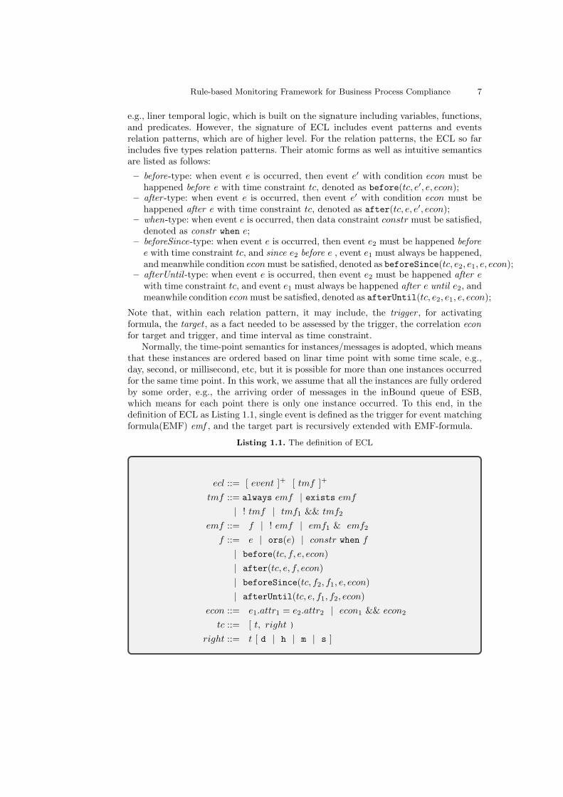
e.g., liner temporal logic, which is built on the signature including variables, functions,and predicates. However, the signature of ECL includes event patterns and eventsrelation patterns, which are of higher level. For the relation patterns, the ECL so farincludes five types relation patterns. Their atomic forms as well as intuitive semanticsare listed as follows:
– before-type: when event e is occurred, then event e′ with condition econ must behappened before e with time constraint tc, denoted as before(tc, e′, e, econ);
– after -type: when event e is occurred, then event e′ with condition econ must behappened after e with time constraint tc, denoted as after(tc, e, e′, econ);
– when-type: when event e is occurred, then data constraint constr must be satisfied,denoted as constr when e;
– beforeSince-type: when event e is occurred, then event e2 must be happened beforee with time constraint tc, and since e2 before e , event e1 must always be happened,and meanwhile condition econmust be satisfied, denoted as beforeSince(tc, e2, e1, e, econ);
– afterUntil -type: when event e is occurred, then event e2 must be happened after ewith time constraint tc, and event e1 must always be happened after e until e2, andmeanwhile condition econmust be satisfied, denoted as afterUntil(tc, e2, e1, e, econ);
Note that, within each relation pattern, it may include, the trigger , for activatingformula, the target , as a fact needed to be assessed by the trigger, the correlation econfor target and trigger, and time interval as time constraint.
Normally, the time-point semantics for instances/messages is adopted, which meansthat these instances are ordered based on linar time point with some time scale, e.g.,day, second, or millisecond, etc, but it is possible for more than one instances occurredfor the same time point. In this work, we assume that all the instances are fully orderedby some order, e.g., the arriving order of messages in the inBound queue of ESB,which means for each point there is only one instance occurred. To this end, in thedefinition of ECL as Listing 1.1, single event is defined as the trigger for event matchingformula(EMF) emf , and the target part is recursively extended with EMF-formula.
Listing 1.1. The definition of ECL
ecl ::= [ event ]+ [ tmf ]+
tmf ::= always emf | exists emf| ! tmf | tmf1 && tmf2
emf ::= f | ! emf | emf1 & emf2
f ::= e | ors(e) | constr when f| before(tc, f, e, econ)
| after(tc, e, f, econ)
| beforeSince(tc, f2, f1, e, econ)
| afterUntil(tc, e, f1, f2, econ)
econ ::= e1.attr1 = e2.attr2 | econ1 && econ2
tc ::= [ t, right )
right ::= t [ d | h | m | s ]
8 Ping Gong, David Knuplesch, and Manfred Reichert
From the synax definition, the structure of ECL is consisted of two parts, events partand rules part. Events part is for event patterns definitions which form the eventsalphabet for ECL formula, whereas within the rules part, rules are specified in tracematching formula tmf , which concerns with the properties of traces; TMF-formula tmfis defined by extending event matching formula emf from event point scope to the tracescope by always or exists qualifiers as well as negation and conjunction operators.Semantically, TMF-formula tmf corresponds to a set of traces which satisfy tmf ; EMF-formula emf is built on a set of atomic formulas, which correspond to the event relationspatterns as listed above, but with the structurally recursive extending which enableECL to describe more complicate rules, e.g., chain pattern [6] as listed in the evaluationsection. Semantically, EMF-formula emf is a set of event points/instances which satisfyemf within a given trace.
Note that, in ECL definition, two negations ! are placed both in TMF and EMF forthe clearity, although one of them can be deleted since the axiom of ! always(emf ) =exists (!emf ). Also, for the conjunction operators for EMF-formula and TMF-formula,′&′ plays the role of connecting two emf operands with the same trigger point andhence requires two operands should have the same trigger, whereas, ′&&′ has not suchrestriction. Furthermore, as classic formal logic, the disjunction“|” and implication“→”can be introduced for EMF formula based on negation and conjunction operators asusual way; so does the “||” and “=>” for TMF-formula.
Correlating condition econ is used to correlate target and trigger instances. In thiswork, econ is defined as equal-based conjunction and also it can be extended if needed.For the time constraint, similar to [14], the time interval [t , right) form is adoptedwhere the left t is a integer and right is another integer followed by a time measurementfrom day to millisecond, for instance, [2, 31d). Note that, usually, the time interval isused to represent a time period before given time point and when representing sometime period after given time point, then the contrary of time interval is needed. Lettc = [t1, t2◦), where ◦ represent the time measurement, then the contrary of tc is tcdefined as [t′2, t
′1◦), where t′2 = −(t2 − 1) and t′1 = −(t1 − 1).
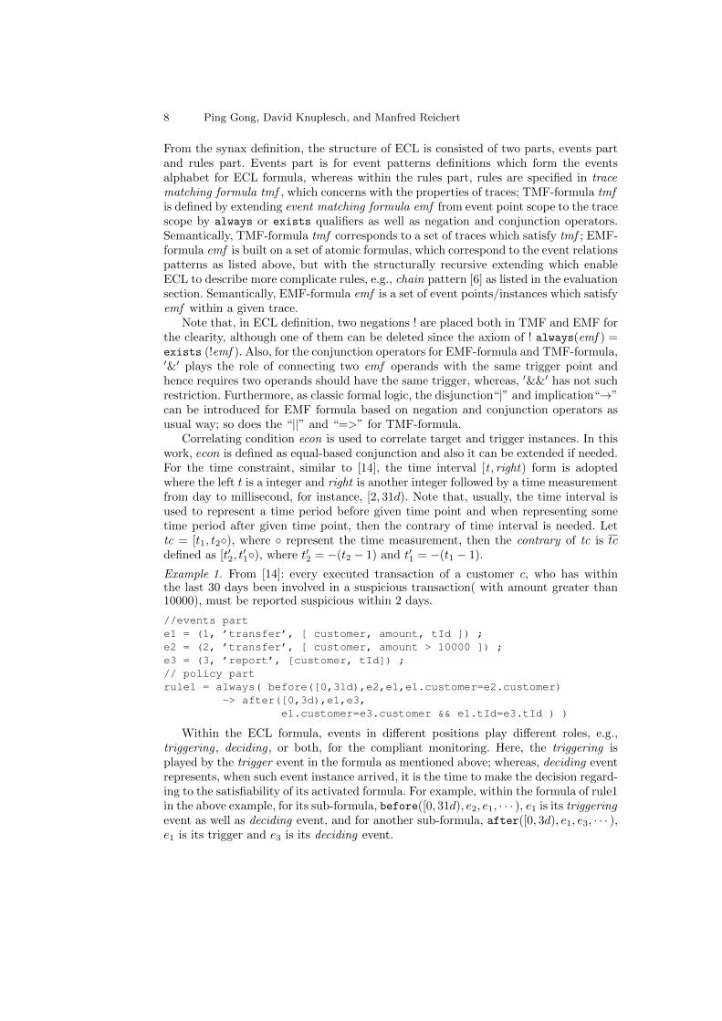
Example 1. From [14]: every executed transaction of a customer c, who has withinthe last 30 days been involved in a suspicious transaction( with amount greater than10000), must be reported suspicious within 2 days.
//events parte1 = (1, ’transfer’, [ customer, amount, tId ]) ;e2 = (2, ’transfer’, [ customer, amount > 10000 ]) ;e3 = (3, ’report’, [customer, tId]) ;// policy partrule1 = always( before([0,31d),e2,e1,e1.customer=e2.customer)
-> after([0,3d),e1,e3,e1.customer=e3.customer && e1.tId=e3.tId ) )
Within the ECL formula, events in different positions play different roles, e.g.,triggering , deciding , or both, for the compliant monitoring. Here, the triggering isplayed by the trigger event in the formula as mentioned above; whereas, deciding eventrepresents, when such event instance arrived, it is the time to make the decision regard-ing to the satisfiability of its activated formula. For example, within the formula of rule1in the above example, for its sub-formula, before([0, 31d), e2, e1, · · · ), e1 is its triggeringevent as well as deciding event, and for another sub-formula, after([0, 3d), e1, e3, · · · ),e1 is its trigger and e3 is its deciding event.

Rule-based Monitoring Framework for Business Process Compliance 9
For a given EMF-formula emf , it is overlapped if it is a before-type or beforeSince-type formula and meanwhile one of its sub-formula is of after -type or afterUntil -type.The overlapped is the relation between triggering and deciding events of given formulaand its sub-formula. For instance, the overlapped formula emf :
before( , after( , e1, e2, ), e, ),
event e is its trigger and also deciding event which requires desired e1 instance mustoccur before, but for its sub-formula, after( , e1, e2, ), e1 is the trigger and e2 is thedeciding event which decides whether desired e1 instance is occurred. The point, whichoverlapped targets at, is that e2 instance could be occurred after e instance for all validtraces of this formula. Then during monitoring, when event e instance was occurred,it would be impossible for the monitor to make decision about whether desired e1
instance was occurred before or not, if meanwhile e2 instance was not occurred yetbut might occurred after e instance. For the overlapped formula, the monitor wouldhave to delay to make its decision when deciding instance occurred. However, for theafter-type formula, even if there is a before-type sub-formula inside, it still belongsto non-overlapped, since the deciding instances of its sub-formula are not allowed tooccur after its deciding instances.
Definition 3. For event matching formula f, the triggering events set, deciding eventsset of f , denoted as tr(f) and de(f), are defined recursively based on formula type asfollows:
– tr(f) = de(f) = {e}, if f = e, or f = constr when e.– tr(f) = de(f) = {ors(e)}, if f = ors(e).– tr(f) = tr(f ′), and de(f) = de(f ′), if f= constr whenf ′.– tr(f) = de(f) = {e}, if f = before(tc, f1, e, econ) or beforeSince(tc, f1, f2,e, econ), and f is non-overlapped.
– tr(f) = {e} and de(f) = de(f1)∪{e}, if f = before(tc, f1, e, econ), or beforeSince(tc, f1, f2, e, econ)and f is overlapped.
– tr(f) = {e}, and de(f) = de(f2), if f = after(tc, e, f2, econ) or afterUntil
(tc, e, f1, f2, econ).– tr(f) = tr(f1) and de(f) = de(f1), if f = ! f1 and f1 6= e and f1 6= ors(e).– tr(f) = tr(f1) ∪ tr(f2) and de(f) = de(f1) ∪ de(f2), if f = f1& f2.
Within EMF-formula, there are two special atomic formulas, i.e.,e and ors(e), sincetheir unsatisfiable are not triggered by themselves but others, for instance, for e, thetrigger for its unsat is not e instance but other instance. Then for f , the set of triggeringevents for its unsatisfiable is, denoted as tr un(f), defined as
tr un(f) =
{ors(tr(f)), if f=e or ors(e);tr(f), o.w.
Based on tr() and de(), a restriction for EMF formula f is made as:
if f = f1 op f2, then tr(f1) = tr(f2),
where op ∈ { |, &, → }. Note that, the intuition behind the restriction is that, twoEMFs should have the same triggering event as connecting points before they wasconnected each other by relevant operators.
An EMF formula is well -formed , if it satisfies the restriction. Note that, for eachwell formed EMF formula f , there is only one triggering event for such formula, i.e.,|tr(f)| = 1. In the following, only well-formed EMF formula is considered.
10 Ping Gong, David Knuplesch, and Manfred Reichert
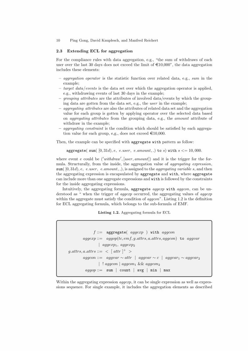
2.3 Extending ECL for aggregation
For the compliance rules with data aggregation, e.g., “the sum of withdraws of eachuser over the last 30 days does not exceed the limit of e10,000”, the data aggregationincludes these elements:
– aggregation operator is the statistic function over related data, e.g., sum in theexample;
– target data/events is the data set over which the aggregation operator is applied,e.g., withdrawing events of last 30 days in the example;
– grouping attributes are the attributes of involved data/events by which the group-ing data are gotten from the data set, e.g., the user in the example;
– aggregating attributes are also the attributes of related data set and the aggregationvalue for each group is gotten by applying operator over the selected data basedon aggregating attributes from the grouping data, e.g., the amount attribute ofwithdraw in the example;
– aggregating constraint is the condition which should be satisfied by each aggrega-tion value for each group, e,g., does not exceed e10,000.
Then, the example can be specified with aggregate with pattern as follow:
aggregate( sum( [0, 31d), e, e.user , e.amount , ) to s) with s <= 10, 000.
where event e could be (′withdraw ′, [user , amount ]) and it is the trigger for the for-mula. Structurally, from the inside, the aggregation value of aggregating expression,sum( [0, 31d), e, e.user , e.amount , ), is assigned to the aggregating variable s, and thenthe aggregating expression is encapsulated by aggregate and with, where aggregate
can include more than one aggregate expressions and with is followed by the constraintsfor the inside aggregating expressions.
Intuitively, the aggregating formula, aggregate aggexp with aggcon, can be un-derstood as “ when the trigger of aggexp occurred, the aggregating values of aggexpwithin the aggregate must satisfy the condition of aggcon”. Listing 1.2 is the definitionfor ECL aggregating formula, which belongs to the sub-formula of EMF.
Listing 1.2. Aggregating formula for ECL
f ::= aggregate( aggexp ) with aggcon
aggexp ::= aggop(tc, emf, g attrs, a attrs, aggcon) to aggvar
| aggexp1, aggexp2
g attrs, a attrs ::= < [ attr ]+ >
aggcon ::= aggvar ∼ attr | aggvar ∼ c | aggvar1 ∼ aggvar2
| ! aggcon | aggcon1 && aggcon2
aggop ::= sum | count | avg | min | max
Within the aggregating expression aggexp, it can be single expression as well as expres-sions sequence. For single example, it includes the aggregation elements as described

Rule-based Monitoring Framework for Business Process Compliance 11
above, where: g attrs, a attrs ∈ SEQ(ATTR) are the attributes sequences for the group-ing and aggregating; EMF-formula emf specifies the desired properties for the triggerevent, of which the target data set is created from the matched instance; aggvar is avariable name in syntax but semantically it is a mapping from group values to aggre-gating values.
For aggregating expression aggexp, it is well -formed if (1) g attrs and a attrs aredisjointed; (2) (g attrs ∪ a attrs) ⊆ attr(e), where e = tr(emf ). In addition, thetrigger and deciding event for aggexp are defined as the same to tr(emf ). Then forthe aggregating formula, it is well -formed , if (1) each of its aggregating expression iswell -formed ; (2) each of its aggregating expressions has the same trigger; (3) each ofits aggregating expressions has the same grouping attributes.
Example 2. From [10]: for each user, the number of withdrawing peaks over the last30 days does not exceed a threshold of 5, where a peak is a value at least twice theaverage over some time window(30 days).
//events parte1 = (’withdraw’, [ user, amount ]) ;// policy partpolicy = always ( aggregate(
avg ([0,31d), e1, <e1.user>, <e1.amount>, _) to ave,cnt ([0,31d), e1, <e1.user>, <e1.amount>,
e1.amount >= 2 * ave ) to c) with c < 5 )
In the example, two aggregating expressions are included in the aggregate and these twoexpressions have the same time interval, grouping and aggregating attributes. Withinthe aggregating constraint of cnt expression, the aggregating variable ave of avg ex-pression is referred to compare with the value of regular attribute. Semantically, thecomparing is finished by comparing each withdrawing amounts with the average valuefor the same user, through one user to another. In fact, such nest structure not onlycomplicates the implementation but also results in expensive running costs which shallbe seen from evaluation section.
2.4 Formal Semantics for ECL
In this section, the semantics of ECL will be defined based on the trace.
Notation: Let INS denote event instances set, then trace τ is a finite sequence inSEQ(INS). For trace τ , τ(i) denotes (i + 1)-th instance in the trace for integer i ≥ 0;|τ | is the length of trace; trace τ is well -formed , if it satisfies, τ(i).ts ≤ τ(j).ts, foreach two non-negative integers i and j with i < j. It means there is a full order overwell-formed trace based on the time stamp attribute, denoted as �. τ≤i denotes thesub trace of τ with the index of its instance not greater than i. We use TRACE to denoteall the well-formed traces of the discourse.
For two traces τ1 and τ2, τ1 is a sub-trace of τ2, denoted as τ1 v τ2, iff, (1) τ1 ⊆ τ2;(2) for instances ins1 , ins2 ∈ τ1, if ins1 � ins2 in τ1, then also ins1 � ins2 in τ2.
τt〈ins〉 denotes the trace after appending ins to the its tail; τ\(i) denotes the traceafter deleting first (i + 1) instances from τ , where i > 0; τ\{ins} denotes the trace
12 Ping Gong, David Knuplesch, and Manfred Reichert
after deleting the first instance ins nearest to the tail; For time interval tc = [t1, t2◦],the bound of tc is non-negative integer b = t2 −◦ t16.
τ ]b 〈ins〉 denotes bounded appending ins to τ , and formally defined as, (τ t〈ins〉)\(k), where k is maximal number of {j| ins.ts −◦ τ(j).ts > b}, i.e., all the out-of-date instances w.r.t. new added ins;
τ ⇑b 〈ins〉 denotes bounded updating τ by ins and defined as τ\(k), where k ismaximal number of (τ t 〈ins〉)\(k). Note that, both operators need to update the τby new instance, but with the difference regrading to whether the new ins needs to beadded.
For instance ins and its attributes attrs ⊆ attr(ins), ins ⇁〈attrs〉 denotes the valuerestriction from ins with respect to attrs;
τ �〈attrs〉 denote the value restrictions set satisfying that, for each value d in theset, there exists at least one instance ins ∈ τ with d = ins|〈attrs〉.
For instances set Ins and attributes set attrs, Ins|〈attrs〉 is a multi-set mt withVALUE〈attrs〉 ⇁ N, where VALUE〈attrs〉 represents the value restrictions domain for at-tributes sequence 〈attrs〉.
The event valuation υe is a binding of EVENT ⇁ INS; event e is satisfied by υe,denoted as υe �em e, iff e is matched by υe(e). For valuation υe, event e, and itsinstance ins, notation υe[e 7→ ins] denotes the updated from υe by e and ins, and [ ]denotes empty valuation. For two valuation υ1, υ2, υ1 is a sub-binding of υ2, denotedas υ1 v υ2, if var(υ1) ⊆ var(υ2) and υ1(x) = υ2(x) ;
Based on event matching notion, following we provide semantics for two eventoperators ors, representing others, and clone, as follows:
Definition 4. For event e, event set E, and event valuation υe, ors(e), ors(E), andclone(e) are events in EVENT, where clone(e).id 6= e.id.υe �em ors(e), iff υe 2em e; υe �em ors(E), iff υe 2em e′, for each e′ ∈ E.υe �em clone(e), iff υe �em e.
Note that, ors operator could be considered as some way of events abstraction, andthe use of operator clone is to distinguish one from another among the copies of sameevent, which will be useful in the creating correlating relations. In fact, based on theevent matching semantics, it is possible to define other composite events patterns ifnecessary.
Definition 5. For events correlating constraint econ, and event valuation υe, the re-lation υe �ec econ is defined as follows :
– υe �ec e1.attr1 = e2.attr2 ⇐⇒ υe �em e1, υe �em e2, and υe(e1)(attr1) =υe(e2)(attr2).
– υe �ec econ1 && econ2 ⇐⇒ υe �ec econ1 and υe �ec econ2.
For time interval [t1, t2◦), where t1, t2 are non-negative integers with t1 < t2, and◦ ∈ {d, h,m, s}, [t1, t2◦) is satisfied by the instances sequence 〈ins1, ins2〉 formed bytwo instances ins1 and ins2, denoted as 〈ins1, ins2〉 �t [t1, t2◦), iff, t1 ≤ ins2(ts) −◦ins1(ts) < t2 .
Semantics for ECL Formula
6 −◦ is the regular operator but calculated based on ◦ scale, hereafter, the notation wouldbe ignored.
Rule-based Monitoring Framework for Business Process Compliance 13
Definition 6. For event matching formula f, trace τ , and integer i ≥ 0, the relationτ(i) � f is defined recursively as follows, where e′ = tr(f1) and e′′ = tr(f2):
– τ(i) � e iff [e 7→ τ(i)] �em e.– τ(i) � ors(e) iff τ(i) 2 e.– τ(i) � constr when f1 iff if τ(i) � f1 and τ(i) � e′, then [e′ 7→ τ(i)] �c constr.– τ(i) � before(tc, f1, e, econ) iff if τ(i) � e, then there exists non-negative
integer j < i, s.t., τ(j) � f1, τ(j) � e′, 〈ins1, ins2〉 �t tc, and [e′ 7→ τ(j), e 7→τ(i)] �ec econ.
– τ(i) � after(tc, e, f1, econ) iff if τ(i) � e, then there exists a non-negativeinteger j > i, s.t., τ(j) � f , τ(j) � e′, 〈ins1, ins2〉 �t tc, and [e 7→ τ(i), e′ 7→τ(j)] �ec econ.
– τ(i) � beforeSince(tc, f1, f2, e, econ) iff if τ(i) � e, then there exists anon-negative integer j < i, s.t., for every integer j < k < i, τ(j) � f1, τ(j) � e′,τ(k) � f2, τ(k) � e′′, 〈ins1, ins2〉 �t tc, and [e′ 7→ τ(j), e′′ 7→ τ(k), e 7→ τ(i)] �ececon.
– τ(i) � afterUntil(tc, e, f1, f2, econ) iff if τ(i) � e, then there exists a non-negative integer j > i, s.t., for every integer i < k < j, τ(j) � f2, τ(j) � e′′,τ(k) � f1, τ(k) � e′, 〈ins1, ins2〉 �t tc, and [e 7→ τ(i), e′ 7→ τ(k), e′′ 7→ τ(j)] �ececon.
– τ(i) � ! f1 iff τ(i) 2 f1.– τ(i) � f1 & f2 iff τ(i) � f1 and τ(i) � f2.
For the TMF formula, its semantics is defined over trace as follows.
Definition 7. For TMF-formula f, f1, f2, EMF-formula emf, and trace τ , the relationτ � f is defined based on two types of f :(1) τ � always emf iff for every i ≥ 0, τ(i) � emf .(2) τ � exists emf iff there exists i ≥ 0, τ(i) � emf .(3) τ � ! f , iff τ 2 f .(4) τ � f1 && f2 iff τ � f1 and τ � f2.
Semantics for AggregationThe semantics of aggregation refers to sliding window model with respect to time
interval.For trace τ ∈ TRACE and time interval tc, the sliding window model with time inter-
val tc within τ up to i, denoted as Mτ≤i(tc), is the sub-trace of τ≤i with 〈ins, τ(i)〉 �t tc
for each its instance ins.For EMF-formula f , Mτ≤i(tc, f) is a sub-trace of Mτ≤i
(tc) with its instance satis-fying ins � f and ins �em e, where e ∈ tr(f). Formally, it is defined as follows:
Mτ≤i(tc, f) =
Mτ≤i−1
(tc, f) ]b 〈τ(i)〉, if τ(i) � fand ins �em e with e = tr(f);
Mτ≤i−1(tc, f) ⇑b 〈τ(i)〉, o.w.
(1)
, for i ≥ 0, and Mτ≤−1(tc, f) = ∅.
Aggregating variable: for aggregating variable aggvar , formally, aggvar is a 3-ary(aname, event , g attrs), where aname, event , and g attrs are the name, involved event,and grouping attributes of aggvar . Aggregating variable is well -formed , if aggvar .g attrs ⊆attr(aggvar .event). Semantically, it corresponds to the partial mapping of VALUE⇁ Q,

14 Ping Gong, David Knuplesch, and Manfred Reichert
which assign a statistic value (e.g., sum, average,etc.) to grouping value in VALUE. Weuse agVAR and agVALUE to denote all the aggregating variables and all aggregating val-ues respectively, meanwhile, agOPS to the aggregation operators set {sum, avg, cnt, min, max},where ω is used to refer the aggregation operator.
Definition 8. For instances sequence θ, two attributes sets g attrs and a attrs, andaggregating operator ω, the aggregating map λag : SEQ(INS)×SEQ(ATTR)×SEQ(ATTR)×agOPS→ (VALUE→ Q) is defined as:
λag(θ, g attrs, a attrs, ω) = χ, (2)
where
– Dom(χ) = θ �〈g attrs〉;– χ(d) = ω(Insd|〈a attrs〉), for each d ∈ Dom(χ);
– Insd = {ins | d = ins|〈g attrs〉, ins ∈ θ}
Within the definition, for the instances sequences, the first equation is to group in-stances based on grouping attributes g attrs; the second one is do the aggregation overgrouped instances set for given grouping value d; the last one is define related instancesgroup for given grouping value.
aggregating valuation υag is a binding of agVAR⇁ agVALUE. then the satisfiable foraggregating constraints could be provided as follow:
Definition 9. For aggregating constraint aggcon, event e, attribute attr, event valu-ation υe, and aggregating valuation υag, aggcon is satisfied by valuations υe and υag,denoted as (υe, υag) �ag aggcon, is defined as follows:
– (υe, υag) �ag aggvar ∼ e.attr, iff, υag(aggvar)(d) ∼ υe(e)(attr) for each d ∈Dom(υag(aggvar)).
– (υe, υag) �ag aggvar ∼ c, iff, υag(aggvar)(d) ∼ c for each d ∈ Dom(υag(aggvar)).
– (υe, υag) �ag aggvar1 ∼ aggvar2, iff, aggvar1.g attrs = aggvar2.g attrs, Dom(υag(aggvar1)) =Dom(υag(aggvar2)), and υag(aggvar1)(d) ∼ υag(aggvar2)(d) for each d ∈ Dom(υag(aggvar1)).
– (υe, υag) �ag !aggcon, aggcon1 && aggvar2, can be defined in standard way.
Then the semantics of aggregating expression can be defined as:
Definition 10. For aggregating expression aggexp, trace τ , and two aggregating valu-ations υag and υ′ag, the relation (τ(i), υag, υ
′ag) � aggexp is defined as follows:
(τ(i), υag, υ′ag) � aggop(f, g attrs, a attrs, aggcon)to aggvar, iff, τ(i) � f , ([e 7→
τ(i)], υag) �ag aggcon, and υag = υag[aggvar 7→ av], where e ∈ tr(f) and av =λag(Mτ≤i
(tc, f), g attrs, a attrs, aggop).
Definition 11. For aggregation event matching formula f and trace τ , τ(i) � f isdefined as follows:
τ(i) � aggregate(aggexp1, aggexp2) with aggcon, iff, there exist two aggregatingvaluations υag and υ′ag, s.t., (τ(i), [ ], υag) � aggexp1, (τ(i), υag, υ
′ag) � aggexp2, and
([e 7→ τ(i)], υ′ag) �ag aggcon, where e ∈ tr(f).

Rule-based Monitoring Framework for Business Process Compliance 15
3 Events indexed reaction system(ERS)
To monitor the full featured ECL, it is necessary to have a uniform and powerfulanalysis theory. In this section, Events Indexed Reaction System(ERS) is proposed,which in fact is the rules system plus working structure. More specifically, ERS is a2-ary(rs,ws), where:(1)rs is the rules system with reaction rules, where reaction is sequence of operationsover working structure;(2) rs is the working structure in charge of organizing instances for their efficientlystoring, consuming, and assessing.
Different to the net form of working memory in RETE algorithm [17] or other ruleengine, ERS working structure is of tree structure including indexing, bounded queue,and also statistics tree for aggregation computing.
3.1 The rules system of ERS
To define the definition of rules system, let notations of ATTR, ECON, TC, agOPS, agVAR ⊆VAR, CONSTR, and agCON, to denote the events attributes set, events correlating con-straints set, time constraints set, aggregating operators set, aggregating variables set,constraints set, and aggregating constraints, respectively; and notation agVALUE ⊆VALUE × VALUE is for aggregating values set; finally, notation BOOL ⊆ VALUE denotesboolean set, and VIOD is a special symbol denoting the fact of without returning inoperation definitions.
Definition 12. The rules system rs of ERS is a 3-ary (E ,OPS ,R), where:(1) E is the events set with E ⊆ EVENT;(2) OPS is the operations set, where each operation is of one of following types:
– delete-operation #d: {0, 1} × EVENT× EVENT −→ VIOD ;– get-operation #g: {0, 1} × EVENT× EVENT× TC −→ SEQ(INS);– write-operation #w: {0, 1} × EVENT× EVENT −→ VIOD;– failure/success-operation #fail, #succ: N× EVENT× EVENT× EVENT −→ VIOD;– next-operation #next: −→ VIOD;– existence-operation #ge: {0, 1} × EVENT× EVENT× TC −→ BOOL;– empty-operation #empty: {0, 1} × EVENT× EVENT −→ BOOL;– evaluation-operation #eval: CONSTR −→ BOOL;– time-comparing-operation #tcm: EVENT× EVENT −→ {−1, 0, 1};– aggop-operation #ω:{0, 1} × EVENT× SEQ(ATTR)× SEQ(ATTR)× agCON× agVAR −→ agVALUE;where ω ∈ {sum, avg, cnt, min, max};
– aggregate-operation #ag: SEQ(agOPS)× agCON −→ BOOL.
(3)R is the rules set and each rule r ∈ R is of the form r : lhs→ rhs, where lhs is theevent from E and rhs is defined as follows:
rhs ::= c reaction
c reaction ::= ops | c reaction ; ops
ops ::= op | op · ops | cond ? ops1 : ops2
op ::= #d | #g | #w | #fail | #succ | #ω
cond ::= #ag | #empty | #ge | #tcm ∼ 0 | #eval
| ! cond | cond1 && cond2

16 Ping Gong, David Knuplesch, and Manfred Reichert
In the definition, event set E is the alphabet for the operation as well as the righthand of rule. For each operations in OPS , most of them share common features: {0, 1},representing the related structure on which operations take effect on, i.e., beforeIIS orafterIIS instances indexed structure which is the main storing mechanism of workingstructure; pair of events EVENT×EVENT with the first one representing target event andthe second for trigger event.
For events e, ta, tr ∈ EVENT, integer i ∈ {0, 1}, and integer t ∈ N, the intuitivesemantics of each operations are briefed listed as follows:
– #d(i, ta, tr) : delete all the correlated ta instances from the related value structureof i instances indexed structure, when tr instance was occurred;
– #g(i, ta, tr, tc) : get all the correlated ta instances within time interval tc fromthe related value structure of i instances indexed structure, when tr instance wasoccurred;
– #w(i, ta, tr) : write the matched ta instances as a new fact into the related valuestructure of i instances indexed structure for the future occurrence of tr instance;
– #fail/succ(t, ta, e, tr) : create a new t-type failure/success information and add itinto the related container of working structure, when tr instance was occurred;
– #next() : terminate current operations executing and go to the next operations ifthere is, otherwise read the next instance;
– #ge(i, ta, tr, tc) : check whether there exists correlated ta instances within timeinterval tc in the related value structure of i instances indexed structure, when trinstance was occurred;
– #empty(i, ta, tr) : check whether it is empty for the value structures determinedby ta and tr in i instances indexed structure.
– #eval(constr) : check whether the constr is satisfiable in current moment.– #tcm(ta, tr) : comparing the time values of current matched ta instance and tr
instance. if ta instance is occurred after tr instance, then return 1; else if their timeis equal, then return 0; otherwise return -1;
– ω(i, e, g attrs, a attrs, aggcon, aggvar): aggregate the values, with g attrs as group-ing attributes and a attrs as aggregating attributes, for all the currently matchede instances which also satisfy aggcon constraints, and use aggvar to refer to suchaggregating values.
– #ag(agops, aggcon): sequentially execute aggregation operators as specified in agops,and then evaluate the aggcon by the aggregating values.
For each rule in rs, it is of the form, event → c reaction. Semantically, it means,when the trigger event is matched, then reaction c reaction is invoked and started toexecute the operations as specified in c reaction. The rule system rs is deterministic ifthere do not exist any two rules in R with same right hand, and ERS is deterministicif its rule system is deterministic. In this work, only deterministic rule system is con-sidered.
For the rule right hand, c reaction, it could be operations expression ops as well asthe compositional reaction, which composites ops with sequential operator “;”. For theops, it could be simple operation, conditional operations, or their connection by thechain operator “·”. Note that, the sequential operator is different to chain operators.The sequential operator is used in the merging of rule systems by connecting relatedreactions to form composite reactions, and during the running, each of these reactionswould be executed sequentially; whereas, chain operators is used to chain operations

Rule-based Monitoring Framework for Business Process Compliance 17
into composite operation and when rule triggered, these operations might not be ex-ecuted all, since if the final operation, #succ/fail , or next operation is included, thefollowed operations would not be executed.
Comparing to classic rule form, e.g., event-condition → action [21], ERS rule hasdistinct characteristics:(1) the left hand is only one event as rule trigger , by which find-ing triggered rule would be speeded up; (2) the conditional operation adopts the formof concise conditional expression, “? : ”, which could speed up conditions evaluationby avoiding repeated conditions evaluation; (3) two distinct connecting operators areused with different purposes.
Example 3. For TMF-formula always ( after( , e6, e7, e6.caseID = e7.caseID) ), thenits rules system can be specified as follows:
ERS :%% wrting e6 instance into the related value structure of e6 for e7e6 -> #w(1,e6,e7)
%% if there is related e6 instance in the structure for e7 instance,%% delete all such e6 instances and create success insances of type2%% for such e6 instances and e7 instance; otherwise, read the next.e7 -> #ge(1, e6, e7) ? #d(1,e6,e7).#succ(2,e6,e7 ):#next()
%% when end event occurred, if the structure of e6 for e7 is%% not empty, then create violation instances of type 3 for%% each such e6 instance; otherwise, read the next.end -> !#empty(1,e6,e7) ? #fail(3,e6,e7):#next()
3.2 Instances Indexed Structure(IIS)
From the above, it should be implied that, the value structure, as the mechanism forstoring instances, is the essential part for explaining and understanding operationsexecutions. Furthermore, to efficiently assess the stored instances, the value structureneeds to be equiped with indexing structure. In this work, we term the instances valuestructure with indexing as instances indexed structure(IIS) and its skeleton structureis a tree as Fig. 2, which is of four layers and with storing mechanism as leaf nodes.
Definition 13. Instances Indexed Structure iis is a 4-ary (Target, Trigger, VS, δ),where :
– Target, Trigger ⊆ EVENT are events sets ;– VS is the value structure set, and value structure vs is defined as
vs=(corr, b, θ),
where:• corr ∈ SEQ(ATTR) is correlating attributes;• b ∈ N ∪ {∞} is the bound of storing mechanism;• θ : VTuple→ SEQ(INS) is a partial one to one mapping assigning to vtuple with
instances storing mechanism.– δ : Target→ (Trigger→VS) is a mapping assign an value structure to target and
trigger.

18 Ping Gong, David Knuplesch, and Manfred Reichert
IIS
6 taID
… 7 trID
instance_1
… <01> vtuple
Storing : bounded/unbounded Queue for event instances
Correlating VTuples
….
instance_n
Target Events
Trigger Events
queue_6_7_01
…
vs : (corr, b, 𝜃)
…
….
…
…
….
…
Fig. 2. Instances indexed structure
Within the IIS, the basis element is value structure, where: corr ∈ SEQ(ATTR) is thecorrelating sequence and its value is a tuple represented as vtuple. Notation VTuple ⊆VALUE denotes all the value of vtuple. By the vtuple and mapping θ, the target in-stances are classified and stored in relevance place. As depicted with dashed rectanglein Fig.2, value structure (corr , b, θ) semantically corresponds to a set of the pair ofvtuple and storing mechanism. Note that, in this work the storing mechanism is thebounded/unbounded queue. For the correlated target and trigger events, the mappingδ not only decides the queue for target instances, but also defines the indexing, i.e.,corr , for storing and assessing target instances. Specifically, storing target instance isdone by first selecting relevance queue though its vtuple and θ; on the other hand,assessing target instance is also finished by first finding relevance queue based on thevtuple of trigger instance. To this end, it is clear that, corr plays the indexing role fortrigger instance finding target one.
As depicted in Fig.2, the queue finding is exactly like finding a path from the top tothe related leaf. Structurally, the IIS in fact is determined by the set of correlating tuples,i.e.,(target , trigger , corr , b), which corresponds set of paths from target and trigger toqueue. For instance in the figure, the path from root, node 6, node 7, < 01 >, toqueue 6 7 01 corresponds to correlating tuple (e6 , e7 , caseID , b), which means, fo eache7 instances, if their caseID is < 01 >, then the storing and assesing for related e6
instances are operated over queue 6 7 01.Intuitively, the IIS is built based on following two frequently and basis operations
during monitoring:
– GET: when trigger instance arrived, it needs to assess the target instance (or fact)occurred before with correlating condition and also might under time bound .
– WRITE: when a target instance arrived, it needs to be saved for behind triggerinstances to assess it with correlating condition and also might under time bound .
However, as for WRITE, after target instances stored, there are two subcases withsubtle differences regarding to whether the stored instance requires the desired trigger

Rule-based Monitoring Framework for Business Process Compliance 19
to be occurred after. Then, IIS is divided into two types: beforeIIS , wherein the storedtarget instance does not require some trigger instance must occur after, and afterIIS ,where each stored target instance requires desired trigger instance must occur after. Forexample, for the operation #w(1 , e6 , e7 ), it writes occurred e6 instance into afterIIS,and for each stored e6 instance, it requires desired e7 to be occurred; on the contrary,if changed 1 to 0 in the operation, e6 instance is stored in beforeIIS for e7 since e7
instance requires desired e6 instance needed to occur before.
Definition 14. For an indexed events reaction system, its working structure ws is a4-ary (beforeIIS, afterIIS, fCon,sCon), where:
– beforeIIS and afterIIS are instances indexed structures;– fCon ∈ SET(Failure) is the failures container, where the failures domain Failure ⊆N× INS× INS× INS.
– sCon ∈ SET(Success) is the success container, where the success domain Success ⊆N× INS× INS× INS.
In the definition, working structure includes not only two types IIS, but also failureand success containers. For convenience, we use ws(0) and ws(1) to denote beforeIISand afterIIS of ws. Currently, 8 types of failures and successes are considered, whichcorresponds to the current set of events relation patterns in ECL. They are createdrespectively by #fail and #succ operators as listed in Table 1, where: type-1 is thebasis; type-2 and type-3 are for before and after order; type-4 is for beforeSince andafterUntil ; type-5 and type-6 are for aggregation and when respectively; type-7 andtype-8 are for emf-composition and exists-tmf formula. For instance, the expression#succ(1, , , e1) would create a type-1 success instance for e1 instance happened, andthen add it into sCon container. Note that, the success and failure instances, createdby #succ and #fail , contain useful debugging information, especially for the failure.
Table 1. The success&failure models
No Success Failure
1#succ(1, , , e1) : #fail(1, , e1, e2): e1 should happene1 instance happened but e2 instance happened
2#succ(2, , e1, e2): #fail(2, , e1, e2):e1 instance happened before e2 instance no e1 happened before e2 instance
3#succ(3, , e1, e2): #fail(3, , e1, e2):e2 instance happened after e1 instance no e2 happened after e1 instance
4#succ(4, e0, e1, e2): e1 always #fail(4, e0, e1, e2): e1 instance happenedhappens after e0 instance and before e2 instance after e0 instance and before e2 instance
5#succ(5, , , e1): the aggcon #fail(5, , , e1): the aggconis satisfied for e1 instance occurring. is unsatisfied for e1 instance occurring.
6#succ(6, , , e1): when-constr #fail(6, , , e1): when-constris satisfied for e1 instance occurring. is unsatisfied for e1 instance occurring.
7#succ(7, , , e1): emf-composition #fail(7, , , e1): emf-compositionis satisfied for e1 instance occurring. is unsatisfied for e1 instance occurring.
8#succ(8, , , e1):exists-tmf #fail(8, , , e1): exists-tmfis satisfied for e1 instance occurring. is unsatisfied for e1 instance occurring.
Within the ERS, reaction rules and working structure are closed related since theassessing and storing operations are executed based on the working structure. Forinstance, when e2 instance occurred, to execute the operation #g(0, e1, e2, ) , findingthe queue, which stores e1 instances, is needed to be done first in such way: get the
20 Ping Gong, David Knuplesch, and Manfred Reichert
value structure (corr , b) by δ(e1)(e2) from beforeIIS; and then get the related queue byθ(vtuple), where vtuple is the correlating value of corr from e2 instance. Such relationis depicted as the coverable property of working structure for rule system as follow:
Definition 15. For working structure ws and rules system rs, ws is coverable for rs,iff for each op ∈ OPS, if the i, ta, and tr are the iis symbol, target, and trigger of oprespectively, then δ(ta)(tr) 6=⊥, where δ is the mapping of ws(i).
Based on the coverable notion, then for ERS ers = (rs,ws), it is well -formed , iff ws iscoverable for rs. In this work, only well-formed ERS is considered.
3.3 Operational semantics of ERS
In this section, the operational semantics of ERS will be defined in SOS-style. In fact,the core of semantics is how to interpret the rule in the system, i.e., how to activatethe rule and react on the read. Regarding to such reaction, it is essentially the statechange of working structure of ERS, i.e., the working structure is the abstract state ofERS.
Definition 16. For event reaction system ERS ers and working structure ws, the con-figuration of ERS is a 2-ary 〈S, υe〉, where S = (Siis, SfCon, SsCon), Siis : {0, 1} ×EVENT× EVENT× VTuple⇁ SEQ(INS) is the state of ws representing the instantaneouscontents of queues in the indexed instances structures in ws, SfCon represents the con-tent of fContainer at state S, and υe is an events valuation.
For simplicity, the subscript of Siis will be ignored when the context is clear. Forinstance sequence queue ∈ SEQ(INS), we use size(queue) to denote the size of queue.For working structure ws, its state S, two events ta and tr, attributes sequence corr ,and event instance ins, we introduce some operators for easy exhibition:
– vs-getting operator: vs(i, ta, tr) = ws(i).δ(ta)(tr);– queue-selecting-for-getting operator: Sqg(S, 0, ta, tr, ins) = queue, where queue =S(i, ta, tr, d) is a bounded queue with bound of vs.bound , where d = ins|vs.corr,vs = vs(i, ta, tr) and tr is matched by ins;
– queue-selecting-for-writing operator: Sqw(S, i, ta, ins, tr) = queue, where queue =S(i, ta, tr, d) is a bounded queue with bound of vs.bound , where d = ins|vs.corr,vs = vs(i, ta, tr) and ta is matched by ins;
– queues-getting operator: SQ(S, i, ta, tr)={q | ∃d ∈ VTuple, q = S(i, ta, tr, d), size(q) >0, and vs = vs(i, ta, tr)};
– queues-updating operator: UPQ(S, i, ta, tr, ins) is a queue set, SQ(S, i, ta, tr) in S, up-dated by ins, where tr is matched by ins. Formally, for each q ∈ UPQ(S, i, ta, tr, ins),let SQ = SQ(S, i, ta, tr), then q is defined based on cases:
q =
q′ ]b 〈ins〉, if ∃q′ ∈ SQ, q′ = Sqg(S, i, ta, tr, ins);〈ins〉, if Sqg(S, i, ta, tr, ins) =⊥;q′ ⇑b 〈ins〉, for all other q′ ∈ SQ.
(3)
– new failure/success operators:newf: N× EVENT× EVENT× EVENT× (EVENT→ INS) −→ SET(Failure).news: N× EVENT× EVENT× EVENT× (EVENT→ INS) −→ SET(Success).
Rule-based Monitoring Framework for Business Process Compliance 21
Based on the configuration of ERS, its dynamics is defined by the reaction of its rulessystem on working structure as follows.
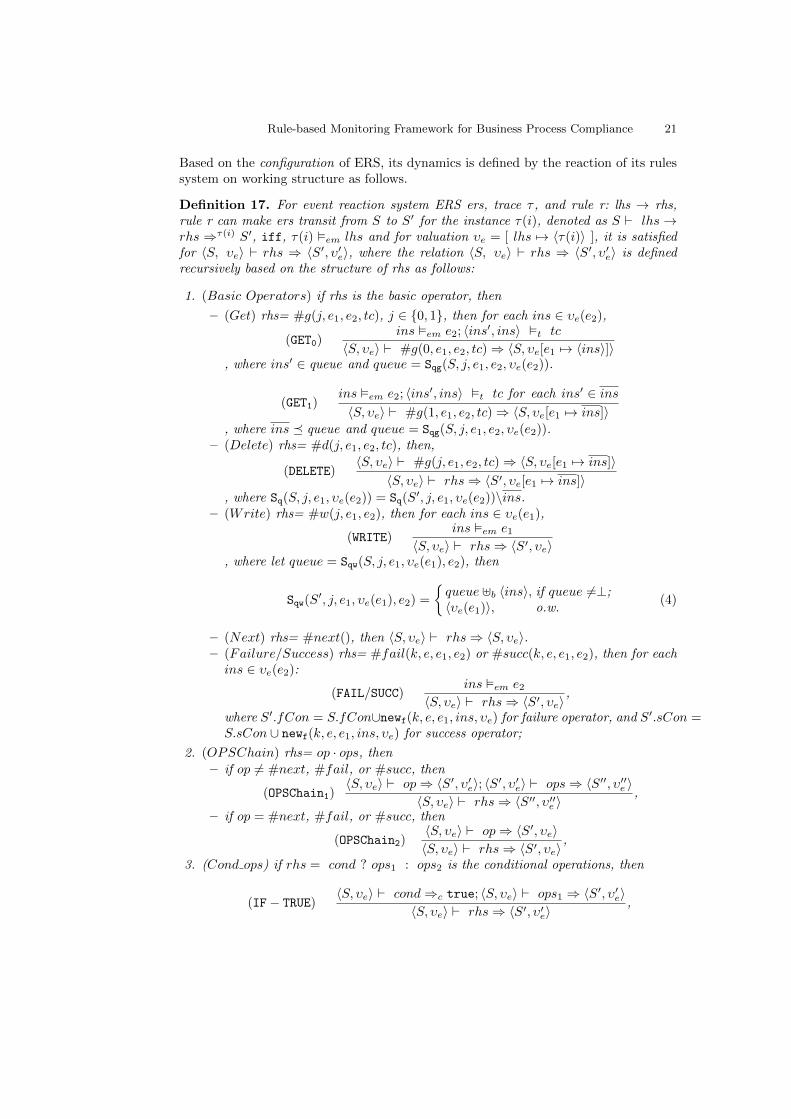
Definition 17. For event reaction system ERS ers, trace τ , and rule r: lhs → rhs,rule r can make ers transit from S to S′ for the instance τ(i), denoted as S ` lhs →rhs ⇒τ(i) S′, iff, τ(i) �em lhs and for valuation υe = [ lhs 7→ 〈τ(i)〉 ], it is satisfiedfor 〈S, υe〉 ` rhs ⇒ 〈S′, υ′e〉, where the relation 〈S, υe〉 ` rhs ⇒ 〈S′, υ′e〉 is definedrecursively based on the structure of rhs as follows:
1. (Basic Operators) if rhs is the basic operator, then
– (Get) rhs= #g(j, e1, e2, tc), j ∈ {0, 1}, then for each ins ∈ υe(e2),
(GET0)ins �em e2; 〈ins′, ins〉 �t tc
〈S, υe〉 ` #g(0, e1, e2, tc)⇒ 〈S, υe[e1 7→ 〈ins〉]〉, where ins′ ∈ queue and queue = Sqg(S, j, e1, e2, υe(e2)).
(GET1)ins �em e2; 〈ins′, ins〉 �t tc for each ins′ ∈ ins〈S, υe〉 ` #g(1, e1, e2, tc)⇒ 〈S, υe[e1 7→ ins]〉
, where ins � queue and queue = Sqg(S, j, e1, e2, υe(e2)).– (Delete) rhs= #d(j, e1, e2, tc), then,
(DELETE)〈S, υe〉 ` #g(j, e1, e2, tc)⇒ 〈S, υe[e1 7→ ins]〉
〈S, υe〉 ` rhs⇒ 〈S′, υe[e1 7→ ins]〉, where Sq(S, j, e1, υe(e2)) = Sq(S
′, j, e1, υe(e2))\ins.– (Write) rhs= #w(j, e1, e2), then for each ins ∈ υe(e1),
(WRITE)ins �em e1
〈S, υe〉 ` rhs⇒ 〈S′, υe〉, where let queue = Sqw(S, j, e1, υe(e1), e2), then
Sqw(S′, j, e1, υe(e1), e2) =
{queue ]b 〈ins〉, if queue 6=⊥;〈υe(e1)〉, o.w.
(4)
– (Next) rhs= #next(), then 〈S, υe〉 ` rhs⇒ 〈S, υe〉.– (Failure/Success) rhs= #fail(k, e, e1, e2) or #succ(k, e, e1, e2), then for eachins ∈ υe(e2):
(FAIL/SUCC)ins �em e2
〈S, υe〉 ` rhs⇒ 〈S′, υe〉,
where S′.fCon = S.fCon∪newf(k, e, e1, ins, υe) for failure operator, and S′.sCon =S.sCon ∪ newf(k, e, e1, ins, υe) for success operator;
2. (OPSChain) rhs= op · ops, then
– if op 6= #next, #fail, or #succ, then
(OPSChain1)〈S, υe〉 ` op⇒ 〈S′, υ′e〉; 〈S′, υ′e〉 ` ops⇒ 〈S′′, υ′′e 〉
〈S, υe〉 ` rhs⇒ 〈S′′, υ′′e 〉,
– if op = #next, #fail, or #succ, then
(OPSChain2)〈S, υe〉 ` op⇒ 〈S′, υe〉〈S, υe〉 ` rhs⇒ 〈S′, υe〉
,
3. (Cond ops) if rhs = cond ? ops1 : ops2 is the conditional operations, then
(IF− TRUE)〈S, υe〉 ` cond⇒c true; 〈S, υe〉 ` ops1 ⇒ 〈S′, υ′e〉
〈S, υe〉 ` rhs⇒ 〈S′, υ′e〉,

22 Ping Gong, David Knuplesch, and Manfred Reichert
(IF− FALSE)〈S, υe〉 ` cond⇒c false; 〈S, υe〉 ` ops2 ⇒ 〈S′, υ′e〉
〈S, υe〉 ` rhs⇒ 〈S, υe〉,
4. (OPSEQ) rhs = c reaction ; ops, then
(OPSEQ)〈S, υe〉 ` c reaction⇒ 〈S′, υ′e〉; 〈S′, υe〉 ` rhs2 ⇒ 〈S′′, υ′′e 〉
〈S, υe〉 ` rhs⇒ 〈S′′, υ′′e 〉,
Following is the definition of conditional expressions valuation.
Definition 18. For ERS configuration 〈S, υe〉 and conditional expression cond, thevaluation cond under configuration, 〈S, υe〉 ` cond⇒c, is defined as follows:
– (Get-Ex) if cond = #ge(j, e1, e2, tc), then
(GETEX− True)〈S, υe〉 ` #g(j, e1, e2, tc)⇒ 〈S, υ′e〉; υ′e(e1) 6=⊥
〈S, υe〉 ` cond⇒c true;
(GETEX− False)〈S, υe〉 ` #g(j, e1, e2, tc) ; 〈S, υ′e〉; υ′e(e1) =⊥
〈S, υe〉 ` cond⇒c false;
– (Empty) if cond = #empty(j, e1, e2), then
(EMPTY− True)queue = Sq(S, j, e1, υe(e2)); size(queue) = 0
〈S, υe〉 ` cond⇒c true;
(EMPTY− False)queue = Sq(S, j, e1, υe(e2)), size(queue) > 0
〈S, υe〉 ` cond⇒c false;
– (TCM) if cond = #tcm(e1, e2) ∼ 0, then
(TCM− True)υe �em e1, υe �em e2, υe(e1).ts ∼ υe(e2).ts
〈S, υe〉 ` cond⇒c true
(TCM− FALSE)υe �em e1, υe �em e2, υe(e1).ts � υe(e2).ts
〈S, υe〉 ` cond⇒c false;
– (EVAL) if cond = #eval(constr), then for ins ∈ υe(e),
(EVAL− True)ins �em e, ins �c constr〈S, υe〉 ` cond⇒c true
(EVAL− FALSE)ins �em e, ins 2c constr〈S, υe〉 ` cond⇒c false
, where e is the involved event in the constr.
Following is devoted to define the evaluations of aggregating operators and aggregatingexpression. To distinguish event and aggvar valuations, ERS configuration is extendedto 〈S, υe, υag〉;
For given state S, event ta, and instance ins, similar to Equation 2, the aggregatingmapping for ERS is defined as
λag(S, ta, ins, a attrs, ω) = χ, (5)
where

Rule-based Monitoring Framework for Business Process Compliance 23
– Dom(χ) =⋃q∈SQ
{q �vs.corr};– χ(d) = ω(q|〈a attrs〉), where d = q �vs.corr and q ∈ SQ;– SQ = UPQ(S, 0, ta, tr, ins), where tr = ta.
Comparting to the aggregating mapping λ in Equation 2 where all the related instancesare scattered in the trace, λ is basically the same except dealing with the relatedinstances in working structure which are classified and stored in the queue based oncorrelating values( or called grouping values in λ case). Also, note that, aggregatingcomputing only takes place over beforeIIS.
Definition 19. For ERS configuration 〈S, υe, υag〉 and aggregating operator#ω(0, e1, g attrs, a attrs, aggvar), the valuation of aggregating operator under config-uration, denoted as〈S, υe, υag〉`#ω(0, e1, g attrs, a attrs, aggvar) ⇒ υag[aggvar 7→ av], is defined as fol-lows:(AGGOP)
ins �em e1; ([e1 7→ ins], υag) �ag aggcon; av = λ(S, e1, ins, a attrs, ω)
〈S, υe, υag〉 ` #ω(e1, g attrs, a attrs, aggcon, aggvar)⇒ υag[aggvar 7→ av]
, where ins ∈ υee1.
Definition 20. For ERS configuration 〈S, υe, υag〉 and aggregation operator#ag(aggops, aggcon), where aggops = aggop; aggops′, the valuation of aggregation ex-pression is defined as follows:
(AGGCOND− TRUE)〈S, υe, υag〉 ` aggop⇒ υ′ag; 〈S, υe, υ′ag〉 ` aggops′ ⇒ υ′′ag; ([e1 7→ ins], υ′′ag) �ag aggcon
〈S, υe, υag〉 ` #ag(aggops, aggcon)⇒c true;
(AGGCOND− FALSE)〈S, υe, υag〉 ` aggop⇒ υ′ag; 〈S, υe, υ′ag〉 ` aggops′ ⇒ υ′′ag; ([e1 7→ ins], υ′′ag) 2ag aggcon
〈S, υe, υag〉 ` #ag(aggops, aggcon)⇒c false;
For ERS, its configuration is the basis notion for its execution semantics.
Definition 21. For events indexed reaction system ers and working structure ws, theconfiguration of ers is a 2-ary 〈S, υe〉, where S = (Siis, SfCon, SsCon), Siis : {0, 1} ×EVENT× EVENT× VTuple⇁ SEQ(INS) is the state of ws representing the instantaneouscontents of queues in the indexed instances structures in ws, SfCon/SsCon representsthe content of failure/success container at state S, and υe : EVENT ⇁ SEQ(INS) is theevents valuation at state S.
For given ERS ers, the initial configuration cg0 is a configuration with the initialstate S0 and intial event valuation υe0 , where υe0(e) =⊥ for each event e and S0(i, ta, tr, vt) =⊥,for each i ∈ {0, 1}, ta, tr ∈ EVENT and vt ∈ VTuple, S0.fCon = ∅, and S0.sCon = ∅;its violated configurations are the configurations with the violated state, which is thestate S with size(S.fCon) > 0; its partially compliant configurations are with thestates satisfying size(S.sCon) > 0 or size(S.fCon) = 0 .
Definition 22. For given ERS ers, its initial configuration cg0, and trace τ :
24 Ping Gong, David Knuplesch, and Manfred Reichert
– (fully compliant) τ is fully compliant with respect to ers up to n, denoted as τ≤n `fers, iff, there exists an executing sequence cg0τ(0)cg1τ(1)cg2, · · · , τ(n − 1)cgnsatisfying:• for each 0 ≤ i ≤ n, if there exists a rule r, such that, if τ(i) �em r.lhs, thencgi ` r.rhs⇒ cgi+1; otherwise cgi = cgi+1;
• for each 0 ≤ i ≤ n, cgi is not a violated configuration.– (partially compliant) τ is partially compliant with ers up to n, denoted as τ≤n `pers, iff, it satisfies the conditions of fully compliant, except for (2), cgn is partiallycompliant.
– τ is fully(partially) compliant with respect to ers, denoted as τ `f ers (τ `p ers),iff, τ≤n `f ers (τ≤n `p ers) and n = |τ |.
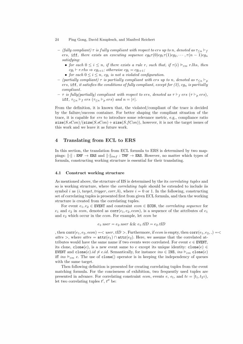
From the definition, it is known that, the violated/compliant of the trace is decidedby the failure/success container. For better shaping the compliant situation of thetrace, it is capable for ers to introduce some relevance metric, e.g., compliance ratiosize(S.sCon)/(size(S.sCon) + size(S.fCon)), however, it is not the target issues ofthis work and we leave it as future work.
4 Translating from ECL to ERS
In this section, the translation from ECL formula to ERS is determined by two map-pings: ‖·‖ : EMF → ERS and ‖·‖tmf : TMF → ERS. However, no matter which types offormula, constructing working structure is essential for their translating.
4.1 Construct working structure
As mentioned above, the structure of IIS is determined by the its correlating tuples andso is working structure, where the correlating tuple should be extended to include iissymbol i as (i, target , trigger , corr , b), where i = 0 or 1. In the following, constructingset of correlating tuples is presented first from given ECL formula, and then the workingstructure is created from the correlating tuples.
For event e1, e2 ∈ EVENT and constraint econ ∈ ECON, the correlating sequence fore1 and e2 in econ, denoted as corr(e1, e2, econ), is a sequence of the attributes of e1
and e2 which occur in the econ. For example, let econ be
e1.user = e2.user && e1.tID = e2.tID
, then corr(e1, e2, econ) =< user , tID >. Furthermore, if econ is empty, then corr(e1, e2, ) =<attrs >, where attrs = attr(e1) ∩ attr(e2). Here, we assume that the correlated at-tributes would have the same name if two events were correlated. For event e ∈ EVENT,its clone, clone(e), is a new event same to e except its unique identity: clone(e) ∈EVENT and clone(e).id 6= e.id. Semantically, for instance ins ∈ INS, ins �em clone(e)iff ins �em e. The use of clone() operator is in keeping the independency of queueswith the same target.
Then following definition is presented for creating correlating tuples from the eventmatching formula. For the conciseness of exhibition, two frequently used tuples arepresented in advance. For correlating constraint econ, events e, e1, and tc = [t1, t2◦),let two correlating tuples t′, t′′ be:
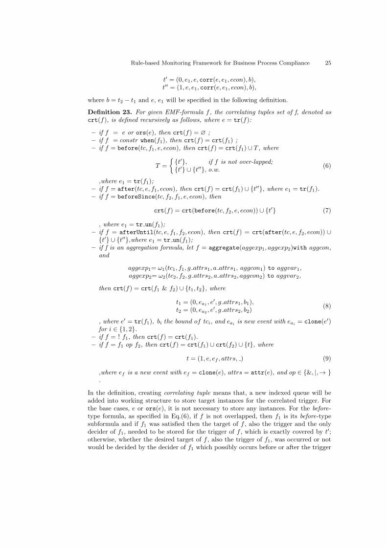
Rule-based Monitoring Framework for Business Process Compliance 25
t′ = (0, e1, e, corr(e, e1, econ), b),t′′ = (1, e, e1, corr(e, e1, econ), b),
where b = t2 − t1 and e, e1 will be specified in the following definition.
Definition 23. For given EMF-formula f , the correlating tuples set of f, denoted ascrt(f), is defined recursively as follows, where e = tr(f):
– if f = e or ors(e), then crt(f) = ∅ ;– if f = constr when(f1), then crt(f) = crt(f1) ;– if f = before(tc, f1, e, econ), then crt(f) = crt(f1) ∪ T , where
T =
{{t′}, if f is not over-lapped;{t′} ∪ {t′′}, o.w.
(6)
,where e1 = tr(f1);– if f = after(tc, e, f1, econ), then crt(f) = crt(f1) ∪ {t′′}, where e1 = tr(f1).– if f = beforeSince(tc, f2, f1, e, econ), then
crt(f) = crt(before(tc, f2, e, econ)) ∪ {t′} (7)
, where e1 = tr un(f1);– if f = afterUntil(tc, e, f1, f2, econ), then crt(f) = crt(after(tc, e, f2, econ)) ∪{t′} ∪ {t′′},where e1 = tr un(f1);
– if f is an aggregation formula, let f = aggregate(aggexp1, aggexp2)with aggcon,and
aggexp1= ω1(tc1, f1, g attrs1, a attrs1, aggcon1) to aggvar1,aggexp2= ω2(tc2, f2, g attrs2, a attrs2, aggcon2) to aggvar2,
then crt(f) = crt(f1 & f2) ∪ {t1, t2}, where
t1 = (0, ea1 , e′, g attrs1, b1),
t2 = (0, ea2 , e′, g attrs2, b2)
(8)
, where e′ = tr(f1), bi the bound of tci, and eai is new event with eai = clone(e′)for i ∈ {1, 2}.
– if f = ! f1, then crt(f) = crt(f1).– if f = f1 op f2, then crt(f) = crt(f1) ∪ crt(f2) ∪ {t}, where
t = (1, e, ef , attrs, ) (9)
,where ef is a new event with ef = clone(e), attrs = attr(e), and op ∈ {&, |,→ }.
In the definition, creating correlating tuple means that, a new indexed queue will beadded into working structure to store target instances for the correlated trigger. Forthe base cases, e or ors(e), it is not necessary to store any instances. For the before-type formula, as specified in Eq.(6), if f is not overlapped, then f1 is its before-typesubformula and if f1 was satisfied then the target of f , also the trigger and the onlydecider of f1, needed to be stored for the trigger of f , which is exactly covered by t′;otherwise, whether the desired target of f , also the trigger of f1, was occurred or notwould be decided by the decider of f1 which possibly occurs before or after the trigger

26 Ping Gong, David Knuplesch, and Manfred Reichert
of f , then both t′ and t′′ are needed to cover these two cases. For the beforeSince-typeformula, the Eq.(7) describes, the correlating tuples of f include the tuples from itsbefore-type formula and also the new tuple t′ which corresponds to the unmatchedinstances w.r.t. trigger of f1. For the aggregation-type fomrula, with two aggexp as inthe definition, the crt(f) should firstly include crt(f1&f2) to enable the generatedworking structure to cover the rule systems for f1 and f2. In addition, for supportingthe aggregating operators ω1 and ω2, t1 and t2 are needed to describe the independentqueues for storing the triggers of f1 and f2 respectively, where the grouping attributesare used as correlating sequences as specified in Eq.(8). For the compositional EMF-formula, besides including the correlating sequences set for its subformulas, the crt(f)also contains the new tuple t as Eq.(9), which characterizes an independent queue inafterIIS for storing the trigger of f and also for communicating the satisfiable situationsfor the subformulas.
Based on the correlating tuples, the working structure for event matching formulacan be constructed as follows.
Definition 24. For correlating tuples set crt, the working structure from crt, denotedas ws(crt), is constructed as:
– (fContainers/sContainters) sCon=fCon=∅ .– (beforeIIS/afterIIS ) for the IIS of ws(crt), where i ∈ {0, 1}:• (Target) Target = {e | for each t = (i, e, e′, corr, b) ∈ crt}.• (Trigger) Trigger = {e′ | for each t = (i, e, e′, corr, b) ∈ crt}.• (VStructure) VS = {(corr, b, ) | for each t = (i, e, e′, corr, b) ∈ crt)}, where
‘ ’ represents the empty mapping for θ.• (δ) δ(e)(e′) = (corr, b, ), if there exists a tuple (i, e, e′, corr, b) ∈ crt}.
Furthermore, for two working structure ws1 and ws2, then the merging of ws1 andws2, denoted as ws1 ]ws ws2, is ws = (beforeIIS , afterIIS , fCon, sCon) where:
– fCon = ws1 .fCon and fCon = ws1 .fCon.– (IIS ) let iis ∈ {beforeIIS , afterIIS} and it is created as follows(i ∈ {0, 1}):• Target = iis1 .Target ∪ iis2 .Target.• Trigger = iis1 .Trigger ∪ iis2 .Trigger.• VS = iis1 .VS ∪ iis2 .VS.• δ(e)(e′) = (corr, b), if (corr, b) = iis1.δ(e)(e
′) or (corr, b) = iis2.δ(e)(e′) for
each e ∈ iis.Target and e′ ∈ iis.Trigger.
For given EMF-formula f , its working structure ws(crt(f)) will be abbreviated as ws(f)for simplicity. Then based on above definitions, the working structure for TMF-formulacould be created as following definition.
Definition 25. For given TMF-formula f, its working structure, denoted as wstmf(f),is constructed based on the types of f as follows:
– wstmf(f) = ws(f1), if f = always(f1).– wstmf(f) = ws(f1) ]ws ws({t}), if f = exists(f1), where
t = (1, e1, end, corr(e1, end, ), 1) (10)
, and e1 = tr(f1).

Rule-based Monitoring Framework for Business Process Compliance 27
– wstmf(f) = ws(f1), if f =!f1.– wstmf(f) = ws(f1) ]ws ws(f2), if f = f1 op f2, where op ∈ { &&, ‖ }.
In the definition, correlating tuple t as Eq.(10) is used to specify the related queuefor storing the trigger instances which will be assessed to check whether f1 was satisfiedbefore the end of trace.
Note that, in the above when adding new correlating tuple, there might be the caseof two correlating tuples intersecting with each other, which corresponds to two tuplest1 and t2 ,
t1 = (i, e11, e12, < attr1 >, b1)t2 = (i, e21, e22, < attr2 >, b2),
with e11 = e21 and e12 = e22. For such intersecting case, there would result in sharingmemory for different rules in the rule system, however, if there exists some conflictedactions from different reactions over such sharing memory, e.g., writing and deletingoperators, then different execution orders of these actions would result in inconsistencyoutcomes. For such issue, it would be solvable by extending current δ mapping and/orusing clone operator to replicate the target event.
0
e16
e14
( caseID, _,_) Value Structures
Target Events
Trigger Events
WS
1
e14
e16 end
IIS symbols
( caseID, _,_) ( caseID, _,_)
Fig. 3. The working structure for formula f in Eq.(11).
Example 4. Considering the TMF-formula
f1 = always( afterUntil( , e14, ors(e16), end,e14.caseID = ors(e16).caseID &&e14.caseID = end.caseID ) )
(11)
, where events defintions are presented in following evaluation section, it specifies thatfor each running instances, after each e14 instances, e16 instances are not allowed tooccur. Its working structure is depicted as Fig. 3, where leaf nodes in left dashed partare created based on the Def.23 for afterUntil -type formula, and the right dashed partfollows the defintion for after -type formula. Note that, in the tree, one path from rootto the leaf node corresponds to one correlating tuple, and for the leaf node (caseID , , ),caseID is the correlating attribute and the first “ ” represents no boundness for thequeue.

28 Ping Gong, David Knuplesch, and Manfred Reichert
4.2 Translating to ERS
In this section, the rules system for the ECL formula will be presented recursively basedon the structure of formula.
Before diving into the translation, some operator over rules are needed. For rulesset R, a rule r, an event e, events set E, operations ops, and operation op, op1, theneeded rule operators are defined as follows:
– (rule selection) R † (e): select from R the rule with e as its left hand.
R † (e) =
{r, if ∃ r ∈ R, s.t., r.lhs = e,∅, o.w.
– (rule deleting) R\r(e): delete from R the rule with e as its left hand.
R\r(e) =
{R\{r}, if ∃ r ∈ R, s.t., r.lhs = e,∅, o.w.
– (rules merging in chain) R]c (r): add rule r into set R, if there was the other ruler′ in R sharing the same left hand of r, then right hand of r was chained to righthand of r′.
R ]c (r) =
(R\{r′}) ∪ {r′′}, if r′ = R † (r.lhs),
where r′′.lhs = r′.lhs andr′′.rhs = r′.rhs · r.rhs
R ∪ {r}, o.w.– (rules merging in sequence) R ]s {r}: add rule r into set R, if there was the other
rule r′ in R sharing the same left hand of r, then right hand of r was sequentiallyappended to right hand of r′.
R ]s {r} =
(R\{r′}) ∪ {r′′}, if r′ = R † (r.lhs),
where r′′.lhs = r′.lhs andr′′.rhs = r′.rhs ; r.rhs
R ∪ {r}, o.w.– (rule renaming) R[e : op1 � ops]: replace in R with ops for all the op1 occurred
in the right hand of e rule. Also, it is possibly extended to the events set caseR[E : op1 � ops].
– (operation deleting) R\o{op}: delete operation op occurred in rules of R.R\o{op} = R[E : op� #next], where E = { r.lhs | r.rhs ∩ op 6= ∅, r ∈ R}.
– (rule concreting for ors) R ⇓c E: for all the rules in R with ors event as left hand,replace the left hand of these rules for each events from E which are not the basefor the ors event.R ⇓c E = {r | r.lhs ∈ E\{e} and r.rhs = r′.rhs, for each r′ ∈ R with r′.lhs =ors(e)}.
Note that, for rules concerting operator, if there was no rules in R with ors event asleft hand, then the result would be empty set.
Based on above rule operators, the translating for given EMF formula is presentedin the following.
Definition 26. For given events set E and event matching formula f, the mapping‖ ‖ : EMF → ERS is the translation from EMF formula to ERS, where the workingstructure of ‖f‖ is ws(f) and the rules system (E,OPS , R) with the rules set R = (R′]c(R′ ⇓c E))\{ors}, where R′ is constructed recursively. Let e1 ∈ tr(f1), e2 ∈ tr(f2),and e′ ∈ tr un(f1), then:

Rule-based Monitoring Framework for Business Process Compliance 29
– if f = e, then
R′ = { e→ #succ(1, , , e), ors(e)→ #fail(1, , e, ors(e))}.
– if f = ors(e), then
R′ = { e→ #fail(1, , ors(e), e), ors(e)→ #succ(1, , , ors(e))}.
– if f = constr whenf1, then
R′ = (‖f1‖.R)\o{#fail}[de(f1) : #succ� ops)];ops = #eval(constr)?#succ(6, , , e1) : #fail(6, , , e1).
– if f = before(tc, f1, e, econ), then
R′ = R+ ]c R∗,
where R+ and R∗ are defined based on following cases and time interval tc is thecontrary of tc:• f is non-overlapped,
R+ = {e→ #ge(0, e1, e, tc)?#succ(2, , e1, e) : #fail(2, , e1, e)}R∗ = (‖f1‖.R)[de(f1) : #succ� #w(0, e1, e))]\o{#fail};
(12)
• f is overlapped,
R+ = { e→ #ge(0, e1, e, tc)?#succ(2, , e1, e) : #w(1, e, e1),end→!#empty(1, e, e1)?fail(2, , e1, e) }
R∗ = (‖f1‖.R)[de(f1) : #succ� ops]\o{#fail};ops = #ge(1, e, e1, tc)?#d(1, e, e1) ·#succ(2, , e1, e) : #w(0, e1, e)
(13)
– if f = after(tc, e, f1, econ), then
R′ = R+ ]c R∗,
,where
R+ = { e→ #w(1, e, e1),end→!#empty(1, e, e1)?#fail(3, , e, e1) }
R∗ = (‖f1‖.R)[de(f1) : #succ� ops)\o{#fail}.ops = #ge(1, e, e1, tc)?#d(1, e, e1) ·#succ(3, , e, e1).
– if f = beforeSince(tc, f2, f1, e, econ) and f1 is non-overlapped, then
R′ = R+ ]c (R∗\o{#succ})
, where
R+ = (‖before(tc, f2, e, econ)‖.R)[e : #succ� ops];R∗ = (‖f1‖.R)[e′ : #fail � #w(0, e′, e)]ops = con ? #fail(4, e2, e
′, e) : #succ(4, e2, e1, e)con = #ge(0, e′, e, tc)&&#tcm(e′, e2) > 0
– if f = afterUntil(tc, e, f1, f2, econ) and f1 is non-overlapped, then
R′ = R ]c R+ ]c (R∗\o{#succ})

30 Ping Gong, David Knuplesch, and Manfred Reichert
, where
R+ = { e→ #w(1, e, e′)}R∗ = (‖f1‖.R)[e′ : #fail � ops1]R = (‖after(tc, e, f2, econ)‖.R)[de(f2) : #succ� ops2]
ops1 = #ge(1, e, e′, tc)?#d(1, e, e′) ·#w(0, e′, e)ops2 = #ge(0, e′, e, tc) ? #fail(4, e, e′, e2) : #succ(4, e, e1, e2)
(14)
– if f =!f1, then
R′ = ‖f1‖.R[de(f1) : #succ� #fail,#fail � #succ].
– if f = f1 & f2, then
R′ = R∗1 ]c R∗2
, where
R∗1 = (‖f1‖)[de(f1) : #succ� ops]R∗2 = (‖f2‖)[de(f2) : #succ� ops]ops = #ge(1, ef , e, )?#d(1, ef , e) ·#succ(7, , , e) : #w(1, ef , e).
– if f = f1 | f2, then
R′ = R+ ]c R∗1 ]c R∗2
, whereR+ = { e→ #w(1, ef , e)
end→ !#empty(1, ef , e)?#fail(7, , , e)}R∗1 = (‖f1‖)\o{#fail}[de(f1) : #succ� ops]R∗2 = (‖f2‖)\o{#fail}[de(f2) : #succ� ops]ops = #ge(1, ef , e, )?#d(1, ef , e) ·#succ(7, , , e)
(15)
From above definition, it shall be seen that, the integral part of translation is creatingrule system, which should follow the semantics of ECL formula. Basically, for givenformula f , creating its rule system is to specify, how to decide at decisional time pointsthe compliant/violation state of the rule system, after instances of triggers from tr(f)and tr un(f) occur, where decisional time points refer to the arrivals of its decidersinstances.
For before-type formula f , the translation is devided into two cases based on whetherf is of overlapped or not. If f is not overlapped, then f1 would be non-overlapped beforesubformula of f , which means the decider of f1, also its trigger, is requried to occurbefore e. Thereby, as specified by e rule in R+ of Eq.(12), at time point of e instancearriving, it is decidable for e regarding to the compliant/violation of f by checkingwhether desired e1 instance was occurred before. However, if f is overlapped, its rulesystem is more complicated, since the decider e can not make full decision when thedecider instance of f1 occurs after certain e instance. Thereby, as specified in Eq.(13),e rule copes with the case of desired e1 instance as occurred before, end rule is to thecase of no desired e1 instances occurred, and operations ops in rules of f1 deciders dealwith the case of desired e1 instance occurred but decided at time points of f1 deciders,whose instances might occur after certain e instance. For afterUntil formula, firstly,the trigger e instance should be writted into the afterIIS to require desired outcomes

Rule-based Monitoring Framework for Business Process Compliance 31
happened after. R is used to decide whether e instance is followed by desired e2 at timepoints of f2 deciders arriving. If the desired e2 occurred for e instance, operations ops2
would decide for such instance the compliant/violation of f , by checking whether afterthe e instance there is e′ instance occurrence, which is corresponding to violation of f1
and determined by R∗. For the disjunction of two EMF formulas, one of rule systemsfor these formulas needs to be in compliant state for trigger instances. Thereby, asspecified in Eq.(15): firstly, the trigger e instance is written into afterIIS to requireone of rule systems for subformulas to be compliant; then two R∗ devote to decidethe compliant situation for each subformulas, and if one of them is compliant, the rulesystem for the disjunction is compliant and otherwise, end rule would be triggered laterto invoke the fail operation.
Following definition is the translation for aggregation formula.
Definition 27. For aggregation formula f = aggregate(aggexp1, aggexp2)with aggcon and let
aggexp1 = ω1(f1, g attrs1, a attrs1, aggcon1) to aggvar1,aggexp2 = ω2(f2, g attrs2, a attrs2, aggcon2) to aggvar2,
where f1 and f2 are of non-overlapped before type formulas, then the translation ‖ ‖ :EMF → ERS for aggregation formula f is ‖f‖, where ws(f) is its working structureand its the rules system is (E,OPS,R) with
E = ‖f1‖.E ∪ ‖f2‖.E,R = (‖f1 &f2 ‖.R)[e : #succ� c ops]\o{#fail}
, where e = tr(f1) and
c ops = w ops ·#ag(op1.op2, aggcon) ? #succ(5, , , e) : #fail(5, , , e)w ops = #w(0, ea1 , e) ·#w(0, ea2 , e)op1 = #ω1(0, ea1 , g attrs1, a attrs1, aggcon1, aggvar1)op2 = #ω2(0, ea2 , g attrs2, a attrs2, aggcon2, aggvar2)
(16)
From the definition, it shall be seen that, before invoking aggregation operations, rulesystem for the conjunction of f1 and f2 should be in compliant state which is decided bye instance, i.e. the trigger and also decider for f1 and f2; then as specified in Eq.(16), theinstance is written sequentially into two queues and also two aggregation operationsare invoked to do the aggregation over related data queues; finally, the success/failoperation is invoked based on the aggcon result evaluated by aggregation data.
Based on the translation for EMF formula, following is devoted to the TMF formula.
Definition 28. For given events set E and TMF f, the mapping ‖·‖tmf : TMF → ERSis the translation from TMF formula to ERS, where the working structure of ‖f‖tmfis wstmf(f) and its rules system is (E,OPS , R). Let e1 ∈ tr(f1), e2 ∈ tr(f2), ande′ ∈ tr un(f1) ), then its rule set R is constructed as follows:
– if f = alwaysf1, then R = ‖f1‖.R;– if f = existsf1, then
R = R∗ ]c R+,
where
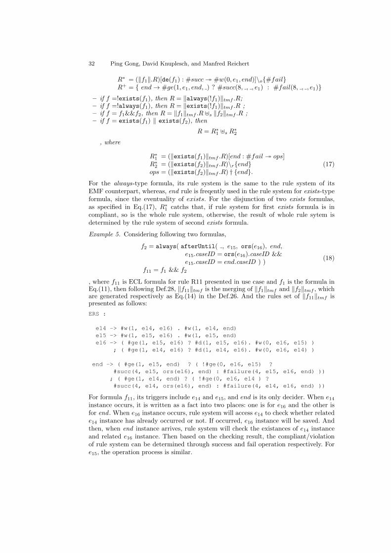
32 Ping Gong, David Knuplesch, and Manfred Reichert
R∗ = (‖f1‖.R)[de(f1) : #succ� #w(0, e1, end)]\o{#fail}R+ = { end→ #ge(1, e1, end, ) ? #succ(8, , , e1) : #fail(8, , , e1)}
– if f =!exists(f1), then R = ‖always(!f1)‖tmf .R;– if f =!always(f1), then R = ‖exists(!f1)‖tmf .R ;– if f = f1&&f2, then R = ‖f1‖tmf .R ]s ‖f2‖tmf .R ;– if f = exists(f1) ‖ exists(f2), then
R = R∗1 ]s R∗2, where
R∗1 = (‖exists(f1)‖tmf .R)[end : #fail � ops]R∗2 = (‖exists(f2)‖tmf .R)\r{end}ops = (‖exists(f2)‖tmf .R) † {end}.
(17)
For the always-type formula, its rule system is the same to the rule system of itsEMF counterpart, whereas, end rule is freqently used in the rule system for exists-typeformula, since the eventuality of exists. For the disjunction of two exists formulas,as specified in Eq.(17), R∗1 catchs that, if rule system for first exists formula is incompliant, so is the whole rule system, otherwise, the result of whole rule sytem isdetermined by the rule system of second exists formula.
Example 5. Considering following two formulas,
f2 = always( afterUntil( , e15, ors(e16), end,e15.caseID = ors(e16).caseID &&e15.caseID = end.caseID ) )
f11 = f1 && f2
(18)
, where f11 is ECL formula for rule R11 presented in use case and f1 is the formula inEq.(11), then following Def.28, ‖f11‖tmf is the merging of ‖f1‖tmf and ‖f2‖tmf , whichare generated respectively as Eq.(14) in the Def.26. And the rules set of ‖f11‖tmf ispresented as follows:
ERS :
e14 -> #w(1, e14, e16) . #w(1, e14, end)e15 -> #w(1, e15, e16) . #w(1, e15, end)e16 -> ( #ge(1, e15, e16) ? #d(1, e15, e16). #w(0, e16, e15) )
; ( #ge(1, e14, e16) ? #d(1, e14, e16). #w(0, e16, e14) )
end -> ( #ge(1, e15, end) ? ( !#ge(0, e16, e15) ?#succ(4, e15, ors(e16), end) : #failure(4, e15, e16, end) ))
; ( #ge(1, e14, end) ? ( !#ge(0, e16, e14 ) ?#succ(4, e14, ors(e16), end) : #failure(4, e14, e16, end) ))
For formula f11, its triggers include e14 and e15, and end is its only decider. When e14
instance occurs, it is written as a fact into two places: one is for e16 and the other isfor end . When e16 instance occurs, rule system will access e14 to check whether relatede14 instance has already occurred or not. If occurred, e16 instance will be saved. Andthen, when end instance arrives, rule system will check the existances of e14 instanceand related e16 instance. Then based on the checking result, the compliant/violationof rule system can be determined through success and fail operation respectively. Fore15, the operation process is similar.

Rule-based Monitoring Framework for Business Process Compliance 33
4.3 The soundness of translation
Now, it is the time to consider the soundness of the above translation. As known fromabove, the working structure plays essentially fundamental roles in the interpretationand execution of ERS. Then it is necessary to make sure firstly the coverable relationbetween working structure and rules system.
Lemma 1. For given TMF-formula f, the rule system of ‖f‖tmf is covered by theworking structure wstmf(f).
The proof can be completed by comparing the definitions for creating working structureand rule systems based on the type of formula.
Semantically, TMF formula is to specify the properties of running trace, while theEMF formula is for the properties of certain time-point. Based on Lemma 1, followinglemma is presented for the relation between EMF formula and its corresponded rulesystem generated by ‖ ‖. Also, without loss of generality, we assume that each runningtraces are ended with end instance.
Lemma 2. Let ‖·‖ : EMF → ERS be the translating mapping, then for EMF formulaf and trace τ , and integer i > 0, the follows hold:(1) if τ(i) 2 f , then:
– τ≤i 0f ‖f‖, if f is non-overlapped before-type formula.
– τ 0f ‖f‖, o.w.
(2) ifτ 0f ‖f‖, then τ(i) 2 f for some i < |τ |.
Proof. proof for statement(1) by the induction on formula structure.
– (base)f = e. if τ(i) 2 f , then τ(i) does not match e, then within the rule system of‖f‖, the rule for ors(e) would be triggered and make ‖f‖ transit to violated state,then τ≤i 0f ‖f‖. It also true for f = ors(e) by similar proof.
– f = constr whenf1. if τ(i) 2 f , then by the semantics of when-type formula,τ(i) � f1, τ(i) � e′, and [e′ 7→ τ(i)] 2c constr. Then τ `p ‖f1‖ and then based onthe rules system of ‖f‖, τ 0f ‖f‖.
– f = before(tc, f1, e, econ). if τ(i) 2 f , then τ(i) � e, and let
Trig = { τ(j) | 〈τ(j), τ(i)〉 �t tc, and [e′ 7→ τj , e 7→ τi] �ec econ}, (19)
, where e′ = tr(f1), then for each τ(j) ∈ Trig, τ(j) 2 f1. Following, we shouldprove that, for all such τ(j), it can lead ‖f1‖ to viloated state based on the typeof f1.
• f1 is non-overlapped before-type formula. By induction, τ≤j 0f ‖f1‖. Supposethat, τj does not lead ‖f1‖ to the violated state. Then, since τj � e′, then itwould fire and make the ‖f1‖ reach the success state, based on the rules in‖f1‖. It means, there would be desired event instances occurred before. Hence,τ(j) � f1. It is a contradiction. Then all such τ(j) would lead ‖f1‖ to violatedstates. Following the rules of ‖f‖, it can be inferred that, the τ≤i could lead‖f‖ to violated state. Then τ≤i 0f ‖f‖.

34 Ping Gong, David Knuplesch, and Manfred Reichert
• f1 is an after-type formula. By induction, τ 0 f1 is true. Suppose that, thereexists one τ(j) ∈ Trig which does not lead ‖f1‖ to the violated state. Sinceτ(j) � e′, then based on rules in R+ for after type formula, τ(j) would bestored and when end instance occurred, the τ(j) would already be deleted bythe related rules in R∗. It means that, after τ(j), there would be would be somedesired instance occurred and then for such τ(j) τ(j) � f1. It is a contraction.Then for each such τ(j), there do not exist desired instances occurred after.Based on rules of ‖f‖, τ would lead ‖f‖ to violated state, i.e., τ 0f ‖f‖.
• f1 is an overlapped before-type formula. By induction, τ 0 f1 is true. Similarto above cases, it is true that, for each τ(j) ∈ Trig there is a sub-trace τ ′ withτ(j) ∈ τ ′ which leads ‖f1‖ to violated state. Considering the rules of ‖f‖, it canbe inferred that, the sub-trace after combing event e’s instance would violate‖f‖, i.e., τ 0f ‖f‖.
– f = after(tc, e, f1, econ). if τ(i) 2 f , then τ(i) � e, and let
Resp = { τ(j) | 〈τ(i), τ(j)〉 �t tc, and [e′ 7→ τj , e 7→ τi] �ec econ} (20)
, then for all τ(j) ∈ Resp, τ(j) 2 f1 and then τ(j) � e′. By induction, τ(j) 0f f1 istrue. From the fact of τ(j) � e′, then τ(j) fire ‖f1‖ and then sub-trace τ≥j wouldlead it to violated state, otherwise there would be a contradiction as shown above.Based on rules of ‖f‖, then sub-trace τ≥i would violate ‖f‖.
– Case 4. f = beforeSince(tc, f2, f1, e, econ). if τ(i) 2 f , then τ(i) � e, and let
Trig = { τ(j) | 〈τ(j), τ(i)〉 �t tc, and τ(j) � f2}.
Then, for all the τ(j) ∈ Trig, there exists at least one t(k) with j < k < i and[e′ 7→ τ(j), e 7→ τ(k), e 7→ τ(i)] �ec econ, but τ(k) 2 f1.• if Trig = ∅. Then for all τ(j) with 〈τ(j), τ(i)〉 �t tc, τ(j) 2 f2 would be true.
then by induction, τ≤j 0 f2. From Case 2, τ≤i 0 before(tc, f2, e, econ′), where
econ′ is the part of econ only related to e′ and e. Then based on the rules of‖f‖, τ≤i 0 ‖f‖.
• if Trig 6= ∅. By the induction on τ(k) 2 f1, τ≤k 0 ‖f1‖, then based on the rulesof ‖f‖. the writing operator would be executed and then following the rule ofr(e) in ‖f‖, the condition would be true and then the violated state is reached,then τ≤i 0 ‖f‖.
– Case 5. f = afterUntil(tc, ef1, f2, e, econ). if τ(i) 2 f , then τ(i) � e, and let
Resp = { τ(j) | 〈τ(i), τ(j)〉 �t tc, and τ(j) � f2}.
Then, for all the τ(j) ∈ Resp, there exists at least one t(k) with i < k < j and[e′ 7→ τ(j), e 7→ τ(k), e 7→ τ(i)] �ec econ, but τ(k) 2 f1.• if Resp = ∅. Then for all τ(j) with 〈τ(j), τ(i)〉 �t tc, τ(j) 2 f2 would be true.
then by induction, τ≤j 0 f2. From Case 3, τ≤i 0 after(tc, e, f2, econ′), where
econ′ is the part of econ only related to e′ and e. Then based on the rules of‖f‖, τ≥i 0 ‖f‖.
• if Resp 6= ∅. By the induction on τ(k) 2 f1, τ≥i 0 ‖f1‖, then based on the rulesof ‖f‖. the deleting and writing operator would both be executed and thenfollowing the rule of r(e′) in ‖f2‖, the condition would be false and then theviolated state is reached, then τ≥i 0f ‖f‖.
– Case 6. f =!f1. if τ(i) 2 f , then τ(i) � f1, then τ `p f1. And then τ 0f !f1.

Rule-based Monitoring Framework for Business Process Compliance 35
– Case 7 f = f1&&f2. if τ(i) 2 f , then τ(i) 2 f1 or τ(i) 2 f1. Then by induction,τ(i) 0f f1 or τ(i) 0f f1. No matter which cases, based on rules of ‖f‖, it is correctfor τ 0f ‖f‖.
Proof for statement(2) by induction on formula structure. If τ 0f ‖f‖, based on therule system for ‖f‖:
– (base) f = e. There exists integer i < |τ |, τ(i) ` trun(f). Then τ(i) 2 f . Similarproof for f = ors(e).
– (when) f = constr when f1. Then there exist integer i and trace τ ′, s.t., τ(i) � e1,τ(i) ∈ τ ′, τ ′ `f ‖f1‖, and τ(i) 2 f1. Based on statement(1), τ(i) � f1. Thereby,following the semantics of when formula, then τ(i) 2 f .
– (before) f = before(tc, f1, e, econ). Then there would be integer i < ‖τ‖, s.t., τ(i)makes ‖f‖ transit to violated state. For each τ(j) ∈ Trig as Eq.19, we should proveτ(j) 2 f1 by types of f .
• f is non-overlapped formula. Then f1 would be of before type. Based on therule for event e in ‖f‖, it can be inferred that, for each τ(j) ∈ Trig, thereexist partial trace of τ , τ ′, such that, τ(j) ∈ τ ′, τ(j) � e′, and τ ′ 0f f1. Thenby induction, τ(i) 2 f1. Then for τ(i), each τ(j) ∈ Trig satisfies τ(j) 2 f1,thereby, τ(i) 2 f .• f1 is after type formula. Based on the rule for end event, there would at least
exist one e instance, say τ(i), which does not have desired instance in Trig.Then for each τ(j) ∈ Trig, based on the rules of ‖f1‖, there exists τ partialtrace τ ′, s.t., τ(j) � e′, τ(j) ∈ τ ′, and τ ′ 0f f1, then by induction, τ(j) 2 f1.Then τ(i) 2 f .
• f1 is overlapped before formula. similar to after type.
– (after)f = after(tc, e, f1, econ). Then from the rule for end event, it is inferredthat, there exists integer i ≤ |τ |, s.t., τ(i) � e, and also the set Resp as Eq.20,such that, for each τ(j) ∈ Resp, it can not trigger ‖f1‖ to transit to the successstate in τ . If Resp = ∅, then for τ(i), it does not have desired τ(j) for f1. By thesemantics of after type formula, τ(i) 2 f . On the other hand, if Resp 6= ∅, thenfor each τ(j) ∈ Resp, there would exist τ ’s partial sub-trace τ ′, s.t., τ(j) ∈ τ ′ andτ ′ 0f f1. By induction, it can be inferred that, τ(j) 2 f1. Also by the semantics offormula, τ(i) 2 f .
– (beforeSince)f = beforeSince(tc, f2, f1, e, econ), where f1 is non-overlapped beforeemf formula and let f ′ = before(tc, f2, e, econ
′). Since τ 0 f . Then the fail oper-ation would be invoked to execute at least one time. Based on rule system of ‖f‖,it could be known, there are two places enable invoking fail operations.
• Case 1. fail in ‖f ′‖. Then τ `f ‖f ′‖. By the induction, there exists τ(i), s.t.,τ(i) 2 f ′. Then τ(i) 2 f .• Case 2. fail in ops operations. Then it infers that, there exists event e instanceτ(i) triggering ‖f ′‖ to success state, and also event e′ instance τ(k) with k < iwhich triggers ‖f1‖ transit to violated state. Then for τ(i), since it makes ‖f ′‖transit to success state, it means, there exists τ partial sub-trace τ ′ and τ ′ `f f ′.By statement 1, then there exists event e2 instance τ(j) with τ(j) � f ′ and alsoj < k from the con condition in rule system. Furthermore, for τ(k), there wouldexist τ ′′s partial sub-trace τ ′′, such that, τ ′′ 0 f1. By induction, τ(k) 2 f1 istrue. Combing all these, τ(i) 2 f is true.

36 Ping Gong, David Knuplesch, and Manfred Reichert
– (afterUnitl) f = afterUnitl(tc, e, f1, f2, econ). where f1 is non-overlapped afteremf formula and let f ′ = after(tc, e, f2, econ
′). Since τ 0 f . Then the fail oper-ation would be invoked to execute at least one time. Similar to sinceBefore, it isalso true that, there exists integer i < |τ |, s.t., τ(i) 2 f .
– (!)f =!f1.if τ 0f ‖f‖, then based on the rule system of ‖f‖, by exchanging thesucc and fail operations in rule system of ‖f1‖, it infers that, there would exists τ ’spartial sub-trace τ ′, s.t., τ ′ ` ‖ff1‖. Then by statement 1, there would be integeri < |τ ′|, such that τ ′(i) � f1. Then τ ′(i) 2 f in τ ′. Thereby τ ′(i) 2 f in trace τ istrue since τ ′ is the partial sub trace of τ .
– (& ) f = f1&f2. If τ 0f f , then based on the rule system of ‖f‖, there would existtau’s partial sub-trace τ ′, such that, event e instance, say τ(i), with τ(i) ∈ τ ′ andfor τ(i), τ ′ 0f f1 or τ ′ 0f f2. Let τ ′ 0f f1, then by induction, τ(i) 2 f1. Thenτ(i) 2 f is true.
– (||) f = f1||f2. If τ 0f f , then also based on rule system of ‖f‖, there exists eventef instance τ(i), the clone of e, which triggers the fail operation. Then there wouldexist τ partial sub-trace τ ′, s.t., τ(i) ∈ τ ′, τ ′ 0f ‖f1‖ and τ ′ 0f ‖f2‖. By theinduction on τ ′, τ(i) 2 f1 and τ(i) 2 f2 would both be true. Then τ(i) 2 f for τ ,since τ ′ is the partial sub trace of τ .
– (aggregation)f = aggregate(aggexp1, aggexp2) with aggcon. If τ 0f ‖f‖, thenfrom the rule system, there exists event e instance τ(i) and τ ’s partial sub-trace τ ′,s.t., τ(i) ∈ τ ′ and τ ′ `f ‖f1&f2‖ for τ(i), which infers τ(i) � f1 and τ(i) � f2. Thenafter τ(i) was written into the working structure and two aggregating operationswere executed, there would be aggregating valuation υag, such that, υag 2ag aggcon.Then combing these, it infers that, τ(i) 2 f .
Within the lemma, statement(1) specifies the soundness for rule system and its EMFformula. For non-overlapped before formula, its violation could be timely reported bythe rule system; however for overlapped formula, it would be delayed to end time pointfor the violation report, if there is not time constraint for the future. Furthermore,statement(2) assures the completeness for EMF formula and its rule system. I
Based on Lemma 2, it is assured for the relation between TMF formula and itscorresponded rule system generated by ‖ ‖tmf by following theorem.
Theorem 1. Let ‖·‖tmf : TMF → ERS be the translating mapping, then for TMF -formula f and trace τ , it holds that
(1) if f is of always type, then τ � f iff τ `f ‖f‖;(2) if f is of exists type, then τ � f iff τ `p ‖f‖.
Proof. By induction on the TMF formula structure.
– for always-type formula.• (base) f = alwaysf1, where f1 is EMF formula.
(=>) if τ � f , then for each integer 0 ≤ i < |τ |, τ(i) � f1. Then by Lemma 2,τ `f ‖f1‖. Based on the definition for creating ‖f‖tmf , it is true for ‖f‖tmf =‖f1‖, then τ `f ‖f1‖tmf .(<=) if τ `f ‖f‖tmf , then τ `f ‖f1‖. By Lemma 2, then for each integeri < |τ |, τ(i) � f1. Then τ � f is true.
• (&&) f = f1&&f2, where f1, f2 are the always-type formula.By the induction, it is true for that, τ � fi iff τ `f ‖fi‖tmf for i ∈ {1, 2}.Then if τ � f , then τ `f ‖f1‖tmf and τ `f ‖f2‖tmf . Then based on the

Rule-based Monitoring Framework for Business Process Compliance 37
assumption of no intersecting between ws(f1) and ws(f2), it is true for ‖f‖tmf =‖f1‖tmf ]r ‖f2‖tmf . Thereby, it is true,τ � f iff τ `f ‖f‖tmf .
• (!) f =!exists(f1),if τ � f , then based on the definition, for each integer 0 ≤ i < |τ |, τ(i) �!f1, thenτ � always(!f1). Then based on above prove, it is true for that, τ � always(!f1)iff τ `f ‖always(!f1)‖emf .
– for exists-type formula.• (base)f = existsf1.
(=>) for trace τ , if τ � f , then there exists integer i < |τ |, s.t., τ(i) � f1,then based on Lemma 2, τ `p ‖f1‖. It means that, there is at least one timeof #succ is invoked. Based on the rule specified in R∗ and R+ of ‖f‖tmf , thesucc(8, , , e1) operation would be invoked and executed, which means τ couldlead ‖f‖tmf to partial compliant state, i.e., τ `p ‖f‖tmf .(<=) if τ `p ‖f‖tmf , then from the rule system, τ `p ‖f1‖tmf . then there existsi, s.t., τ(i) � f1. Then obviously, τ � f .
• (||)f = exists(f1)||exists(f2).(=>) if τ � f , then by the definition, τ � exists(f1) or τ � exists(f2). Bythe induction, τ `p ‖(fi)‖tmf , for i ∈ {1, 2}. If τ `p ‖(f1)‖tmf , Then by therules in R∗1 of ‖f‖tmf , τ `p ‖(f)‖tmf . Else if τ `p ‖(f2)‖tmf , then based onthe rule for end in R∗1 of ‖f‖tmf , when end instance occurred, if ops operationwould be invoked, then based on the reactions of ‖f2‖tmf , it would be true forτ `p ‖f‖tmf .
• (&&) f = f1&&f2, where f1, f2 are the exists-type formula.By the induction, it is true for that, τ � fi iff τ `f ‖fi‖tmf for i ∈ {1, 2}.Then if τ � f , then τ `p ‖f1‖tmf and τ `p ‖f2‖tmf . Then based on theassumption of no intersecting between ws(f1) and ws(f2), it is true for ‖f‖tmf =‖f1‖tmf ]r ‖f2‖tmf . Thereby, it is true,τ � f iff τ `p ‖f‖tmf .
• (!) f =!always(f1),if τ � f , then based on the definition, for there exists an integer 0 ≤ i < |τ |,τ(i) �!f1, then τ � exists(!f1). Then based on above prove, it is true for that,τ � exists(!f1) iff τ `p ‖exists(!f1)‖emf .
Note that, to make the theorem conciseness, always type is used to refers to alwaysformulas and their composition by connectives, as well as the negation of exists formula;exists type is similar and include the negation of always formula. In the theorem,statement(1) assures the soundness and completeness for always type formula and itsrule system from the translation; and statement(2) presents such relations for existstype formula and its rules system based on partial compliant sense.
5 Implementation
The bpCMon was implemented in Java. Here, the structure of bpCMon-monitor ispresented as well as basic monitoring procedure. Also, two algorithms are introducedfor the aggregation: reuse-based and statistic B+tree based.
5.1 The implementation of bpCMon-monitor
The basic structure of bpCMon-monitor consists of three parts, working interface,working structure, and rules system:

38 Ping Gong, David Knuplesch, and Manfred Reichert
– working interface: acts as data reader, in charge of reading, filtering and match-ing the outside data into the inner system. It is implemented as Java interfaceWorkingInterface, including the essential methods:• Instance next(): read the instance from the data source;• Event matchToEvent(Instance inst): match the instance to event;• void init() and void close(): initialize and close the working interface.
– working structure: it is implemented as Java class, which include two IIS and con-tainers as well as methods to deal with container. For the IIS, it is also implementedas Java class including an essential map and the methods for operations:• deltaMap : Map < Integer, Map < Integer, ValueStructure >>: corresponds
to the δ in IIS definition.• void add(Instance inst, Integer trID): add the instance into the right place
of value structure by vtuple and related event ids;• Instance get(Integer taID, Instance trigger, Constraint constr, TimeConstraint tc):
get desired taID instance for trigger.• List < Instance > getAll(Integer taID, Instance trigger,Constraint constr, TimeConstraint tc): get all the desired taID instancesfor trigger.
• void delete(Integer taID, Instance trigger, Constraintconstr, TimeConstraint tc): delete the desired taID instance for trigger.
• boolean isEmpty(Integer taID, Instance trigger): check whether the queueof taID for trigger is empty or not.
• void aggregate(String op, Instance trigger, AttrSEQ group,AttrSEQ aggre, Constraint aggcon, String aggVar, Assigment assign): addtrigger into the related queue and then do the op aggregation over all the aggrevalues for each group, and finally save the new value referred by aggvar in theassignment for further using, where Assignment is a class corresponding toevents evaluation in ERS configuration.
– rules system: it is also implemented as Java class including methods for manipu-lating rules:• Reactions getReaction(Integer trID): get the reaction for trID, where Reactions
is a interface including method void doReaction(WorkingStructure ws, Assignment assign) to execute the reaction.
• void replace(Integer trID, int sign, Operation op): replace the final op-erator, i.e., #succ/#fail in the reaction of trID with op, where final operatoris specified by sign;
• RuleMap rulesJoin(RuleMap other): merging two rule systems, wherein thesequential operator is used to connect reactions with the same trigger.
Obviously, the real implementation is far complicate than the above. But it is enoughfor presenting following basic monitoring procedure of bpCMon-monitor.
Listing 1.3. Basic monitoring procedure
1 PROCEDURE ers_monitoring( ers, workingInterface)2 Input: ers, workingInterface3 begin4 var inst, event, assign;5 var reaction ;6 while (true) {
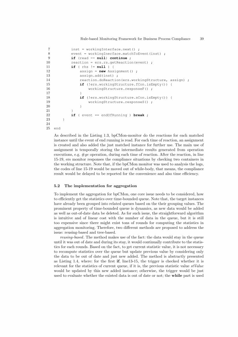
Rule-based Monitoring Framework for Business Process Compliance 39
7 inst = workingInterface.next() ;8 event = workingInerface.matchToEvent(inst) ;9 if (read == null) continue ;
10 reaction = ers.rs.getReaction(event) ;11 if ( rhs != null ) {12 assign = new Assignment() ;13 assign.add(inst) ;14 reaction.doReaction(ers.workingStructure, assign) ;15 if (!ers.workingStructure.fCon.isEmpty()) {16 workingStructure.responseF() ;17 }18 if (!ers.workingStructure.sCon.isEmpty()) {19 workingStructure.responseS() ;20 }21 }22 if ( event == endOfRunning ) break ;23 }2425 end
As described in the Listing 1.3, bpCMon-monitor do the reactions for each matchedinstance until the event of end running is read. For each time of reaction, an assignmentis created and also added the just matched instance for further use. The main use ofassignment is temporally storing the intermediate results generated from operationexecutions, e.g. #ge operation, during each time of reaction. After the reaction, in line15-19, ers monitor responses the compliance situations by checking two containers inthe working structure. Note that, if the bpCMon monitor was used to analysis the logs,the codes of line 15-19 would be moved out of while-body, that means, the complianceresult would be delayed to be reported for the convenience and also time efficiency.
5.2 The implementation for aggregation
To implement the aggregation for bpCMon, one core issue needs to be considered, howto efficiently get the statistics over time-bounded queue. Note that, the target instanceshave already been grouped into related queues based on the their grouping values. Theprominent property of time-bounded queue is dynamics, as new data would be addedas well as out-of-date data be deleted. As for such issue, the straightforward algorithmis intuitive and of linear cost with the number of data in the queue, but it is stilltoo expensive since there might exist tons of rounds for computing the statistics inaggregation monitoring. Therefore, two different methods are proposed to address theissue: reusing-based and tree-based.
reusing-based . The method makes use of the fact: the data would stay in the queueuntil it was out of date and during its stay, it would continually contribute to the statis-tics for each rounds. Based on the fact, to get current statistic value, it is not necessaryto recompute statistics over the queue but update previous value by considering onlythe data to be out of date and just new added. The method is abstractly presentedas Listing 1.4, where: for the first if, line13-15, the trigger is checked whether it isrelevant for the statistics of current queue, if it is, the previous statistic value stValuewould be updated by this new added instance; otherwise, the trigger would be justused to evaluate whether the existed data is out of date or not; the while part is used

40 Ping Gong, David Knuplesch, and Manfred Reichert
to update the stValue for the old data. Comparing to recompute the stValue for eachtime, reusing based one would be more efficient.
Listing 1.4. Reusing-based aggregating computing
1 PROCEDURE aggregate_reusing()2 Input: op , // aggregation operator3 trigger, // new added instance4 group, // grouping attributes5 aggre, // aggregating attributes6 aggcon, // constraint for data selecting7 stValue. // previous statistics value89 Output: stValue
10 begin11 var inst, value, it;1213 if (queue.isRelated(group, trigger) && aggcon.valueOf(trigger)) {14 value = inst.getValue(aggre) ;15 updateByNew(op, stValue, value) ;16 }17 inst = queue.getLast() ;18 while (queue.isOutOfDate(inst, trigger)) {19 if ( aggcon.valueOf(inst) ) {20 value = inst.getValue(aggre) ;21 aggop.updateByOld(op, stValue, value);22 }23 queue.removeLast() ;24 inst = queue.getLast() ;25 }26 return stValue ;27 end
However, the precondition for using reusing-based algorithm is that, the relationbetween the instances and the constraint aggcon is unchanged , which means, for the in-stance in the queue, if it satisfied aggcon in current round, then it would keep satisfyingthe constraint until it was out of date. For example, the constraint, e1.amount ≥ 1000,is of such sort. However, such precondition is not always true. Taking the constrainte1.amount ≥ 2 ∗ av as example, where av is the average amount for given period, con-sidering that, now a new instance with big amount is added into the queue, obviouslythe av would become greater, then in the queue some instances, which used to satisfythe constraint, would not be able to satisfy it again. Such changeability would be pos-sibly occurred if the constraint aggcon includes aggregating variables. For such case,the reusing-based method would not suitable.
tree-based . To address above changeability, we link the queue with a variant ofB+tree, named as statistics annotated B+tree, abbreviated as st-tree. The node typeof st-tree is defined as listing 1.5.
Listing 1.5. node type of st-tree
1 Node2 {3 keys: K[] ; // keys in the node

Rule-based Monitoring Framework for Business Process Compliance 41
4 left: Node ; // left sibling5 right : Node ; // right sibling6 parent : Node ; // parent of node7 statistics : V ; // statistics value8 keyAmount : int ; // the amount of keys9 size : int ; // size of node
10 }11 InnerNode extends Node12 {13 children : Node[] ; // the children of the node14 }15 LeafNode extends Node16 {17 values : V[] ; // the occurring numbers for keys18 }
where, K is aggregating values domain for the instances in the queue; V is the st-valuedomain. Within the queue, all the aggregating values of the instances are orderly storedas key in the leaf nodes of the st-tree as well as their occurring numbers as values sinceaggregating values might equal for different instances. For the inner node, it stores theordered keys which act as the index for searching the key in the leaf, and also includesstatistics value for all the keys stored its descendant leaves. When new instance isadded, its aggregating value is obtained and then as new key inserted into tree. Duringthe traverse for finding the right place to insert, the st-values of traversed node areupdated by this new key. On the other hand, when out of date instance is to be deletedfrom the queue, the aggregating value as key needs also to be deleted from the tree.Similar to insert key, the st-values for all traversed nodes are also updated by the key.Besides, the overflow and underflow of nodes need to be deal with for keys adding anddeleting. The basic operators of st-tree are listed as follows:
– insert(key): when new instance is added into the queue. the value of aggregatingproperty of new instance, as key, is insert into the linked st-tree. Then the methodtraverses the tree from root to leaf through ordered nodes, meanwhile, updates thestatistics of each traversed nodes by key, and then inserts the key to right positionof right leaf node and also updates the occurring value of this key.
– delete(key): when some instance in the queue is to be deleted since out of date,the key w.r.t the instance should also be deleted at same time. The method firsttraverse the tree to find the right leaf node, meanwhile, updates the statistics ofeach traversed nodes by key, and then deletes the key in the leaf node and reducethe occurring value of key.
– dealwithOverflow(node): after key is inserted, the size of the node might be equalto SIZE, then the method will split the node to two nodes and add the mid key upto the parent as standardly processing in B+tree. However, for st-tree, the statisticsof splitted node should also be updated and splitted.
– dealwithUnderflow(node): after key is deleted, the size of the node might be lessthan the half of SIZE, then the method will borrow to the node a key and childfrom its sibling, if one of its sibling has enough keys, i.e., greater than the half ofSIZE. If the node surrounds with poor siblings, the method would merge the nodewith one of its sibling. During borrowing or merging, the statistics of related nodesshould also be updated.
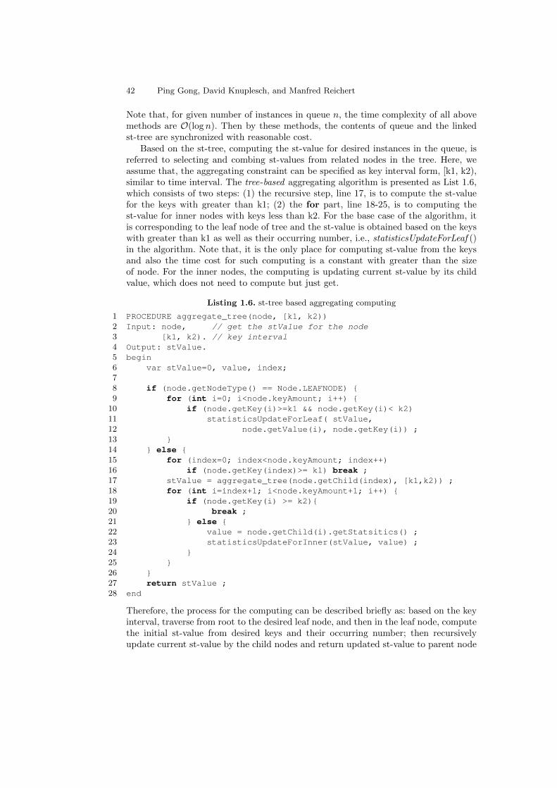
42 Ping Gong, David Knuplesch, and Manfred Reichert
Note that, for given number of instances in queue n, the time complexity of all abovemethods are O(log n). Then by these methods, the contents of queue and the linkedst-tree are synchronized with reasonable cost.
Based on the st-tree, computing the st-value for desired instances in the queue, isreferred to selecting and combing st-values from related nodes in the tree. Here, weassume that, the aggregating constraint can be specified as key interval form, [k1, k2),similar to time interval. The tree-based aggregating algorithm is presented as List 1.6,which consists of two steps: (1) the recursive step, line 17, is to compute the st-valuefor the keys with greater than k1; (2) the for part, line 18-25, is to computing thest-value for inner nodes with keys less than k2. For the base case of the algorithm, itis corresponding to the leaf node of tree and the st-value is obtained based on the keyswith greater than k1 as well as their occurring number, i.e., statisticsUpdateForLeaf ()in the algorithm. Note that, it is the only place for computing st-value from the keysand also the time cost for such computing is a constant with greater than the sizeof node. For the inner nodes, the computing is updating current st-value by its childvalue, which does not need to compute but just get.
Listing 1.6. st-tree based aggregating computing
1 PROCEDURE aggregate_tree(node, [k1, k2))2 Input: node, // get the stValue for the node3 [k1, k2). // key interval4 Output: stValue.5 begin6 var stValue=0, value, index;78 if (node.getNodeType() == Node.LEAFNODE) {9 for (int i=0; i<node.keyAmount; i++) {
10 if (node.getKey(i)>=k1 && node.getKey(i)< k2)11 statisticsUpdateForLeaf( stValue,12 node.getValue(i), node.getKey(i)) ;13 }14 } else {15 for (index=0; index<node.keyAmount; index++)16 if (node.getKey(index)>= k1) break ;17 stValue = aggregate_tree(node.getChild(index), [k1,k2)) ;18 for (int i=index+1; i<node.keyAmount+1; i++) {19 if (node.getKey(i) >= k2){20 break ;21 } else {22 value = node.getChild(i).getStatsitics() ;23 statisticsUpdateForInner(stValue, value) ;24 }25 }26 }27 return stValue ;28 end
Therefore, the process for the computing can be described briefly as: based on the keyinterval, traverse from root to the desired leaf node, and then in the leaf node, computethe initial st-value from desired keys and their occurring number; then recursivelyupdate current st-value by the child nodes and return updated st-value to parent node

Rule-based Monitoring Framework for Business Process Compliance 43
until root node is reached. Hence, the cost for computing st-value is determined by2× h× size × update, where h is the height of tree, size is the size of node, and updateis the cost for given values updating. Let the number of instances in the queue is n, thenthe time complexity for aggregating computing by tree-based algorithm is O(log n).
6 Evaluations
The functionals of bpCMon framework will be firstly evaluated by 10 CMFs [20] whichare the qualitative and suggestive requirements for the compliance monitoring frame-work. And then, to evaluate the expressiveness of language, ECL is used to specifyvarious perspectives of compliance rule patterns. For the applicability of bpCMon, thereal hospital logs is adopted and analysed by bpCMon. To evaluate the performanceof bpCMon monitor, it is compared with three other facilities over the benchmarkfrom [21]. Finally, bpCMon monitor is also evaluated for its aggregation functional bythe synthesized test case7. Note that, if without specifying, the tests are performed onLuna version of Eclipse IDE with jdk-1.8.0 40 in laptop with win7 64-bit OS, Intel(R)i5 CPU 2.4G, and 8G RAM.
6.1 The functionals of bpCMon
The compliance monitoring functionals(CMFs) are the suggestive requirements for thecompliance monitor framework, and they are divided into three categories: modelingrequirements, execution requirements, and user requirements. Regarding to these re-quirements, the situation of bpCMon is presented as follows:
– CMF 1. constraints referring to time. It requires that the modeling language ofmonitoring framework should support qualitative and quantitative temporal orders.In bpCMon, ECL satisfies such requirement thanks to the events relation patternsand time interval defined in ECL.
– CMF 2. constraints referring to data. In this CMF, the data is distinguished intounary data conditions and extended conditions, where unary data conditions refersto constraints involving just one data object and extended conditions relating mul-tiple data objects at same time. In ECL, there are several places embodying itscapability for supporting the unary/extended data conditions, i.e., event constraintsin event definition, events correlating constraints, and aggregating constraints.
– CMF 3. constraints referring to resources. Although resources constraints could beconsidered as a special case of data constraints, this prospective is still promotedas an independent standard since its important and prevailed in BPM. It requiresthat the modeling language should associate resources(e.g., agent, role, organi-zation)with activities, events or something. Also, ECL supports this requirementthanks to its data capability.
– CMF 4. supporting non-atomic activites. The non-atomic activity here means theactivity has time duration. Basically, to support such activities, there are two ways,explicit or implicit, wherein, the explicit way makes use of atomic life-cycles eventsof activities, e.g., start, ready, suspended, aborted, and completed events of activity;
7 The testing data, including logs, benchmarks, and rules specifying, are available at:https://github.com/PingFair/bpCMon

44 Ping Gong, David Knuplesch, and Manfred Reichert
while implicit one associate activities with their time duration. Obviously, this CMFcan be implemented in explicit way in bpCMon.
– CMF 5. supporting lifecycles activites. This CMF requires that the monitor frame-work should has correlating mechanism to link multi atomic events to one sameactivity. Also, this requirement can be supported by events correlation constraintsin ECL.
– CMF 6. supporting multiple-instances constraints. It requires that the frameworkshould support the case of multiple activations for compliance rules in one trace. InbpCMon, for each ECL formula, once its trigger was occurred, it would be activatedimmediately.
– CMF 7. reactively detect and manage violations. For bpCMon monitor, it is de-signed in reactive way and also capable of continuous monitoring even violationoccurred.
– CMF 8. pro-actively detect and manage violations. Comparing to CMF 7, thisCMF requires totally different monitoring mechanism. Obviously, bpCMon nowonly support CMF 7.
– CMF 9 and 10. ablity for root cause of violation and quantifying compliance. InbpCMon, once the success/violation was occurred, its information, including rootcauses for the results, would be created based on success/failure table and thenstored in the related containers. Thereby, the way is paved for further root causeanalysis and quantifying the compliance situation.
Table 2. Compliance patterns in ECL
Categories Patterns ECL description
Occurrence
Existence of A exists AAbsence of A !exists A
Limit A to Nalways(before( , · · · , before( , A,A, ), · · · , A)→afterUntil( , A, ors(A), end, ))
A requires B exists A→ exists BA coexists B (exists A→ exists B)&&(exists B → exists A)A mutex B (exists A→!exists B)&&(exists B →!exists A)Choose A or B exists A || exists B
Order
A followed by B after( , A,B, )A precedes B before( , B,A, )A block B afterUntil( , A, ors(B), end, )A block B until C afterUntil( , A, ors(B), C, )
(A1,· · · , An) chainLeadsTo (B1,· · · , Bm)before( , (· · · before( , A1, A2, ) · · · ), An, )→after( , An, after( , B1, (· · · after( , Bm−1, Bm, ) · · · ), ), )
(A1,· · · , An) chainPrecedes (B1,· · · , Bm)after( , B1, (· · · (after( , Bm−1, Bm, ) · · · ), ))→before( , (· · · before( , A1, A2, ) · · · , An), B1, ))
ResourceP PerformedBy r P.role = rwhen PP SegregatedFrom Q (P.role 6= Q.role)when(before( , Q, P, ) | after( , P,Q, ))P BondedWit Q (P.role = Q.role)when(before( , Q, P, ) | after( , P,Q, ))
TimeP leasTo Q within k after([0, k), P,Q, )P leadsTo Q AtleastAfter k after([k,∞), P,Q, )P precedes Q AtleastAfter k before([k,∞), P,Q, )
In addition, to evaluate the expressiveness of ECL, in Table2, we use ECL to specify thecompliance patterns which cover most part of patterns list proposed in [20][23] exceptsome advanced but rare occurred patterns. Note that, from the definition of ECL, itsexpressive capability is far beyond the expressing of above patterns, since other pow-erful properties has not yet used, e.g., event constraints, event correlating, aggregating
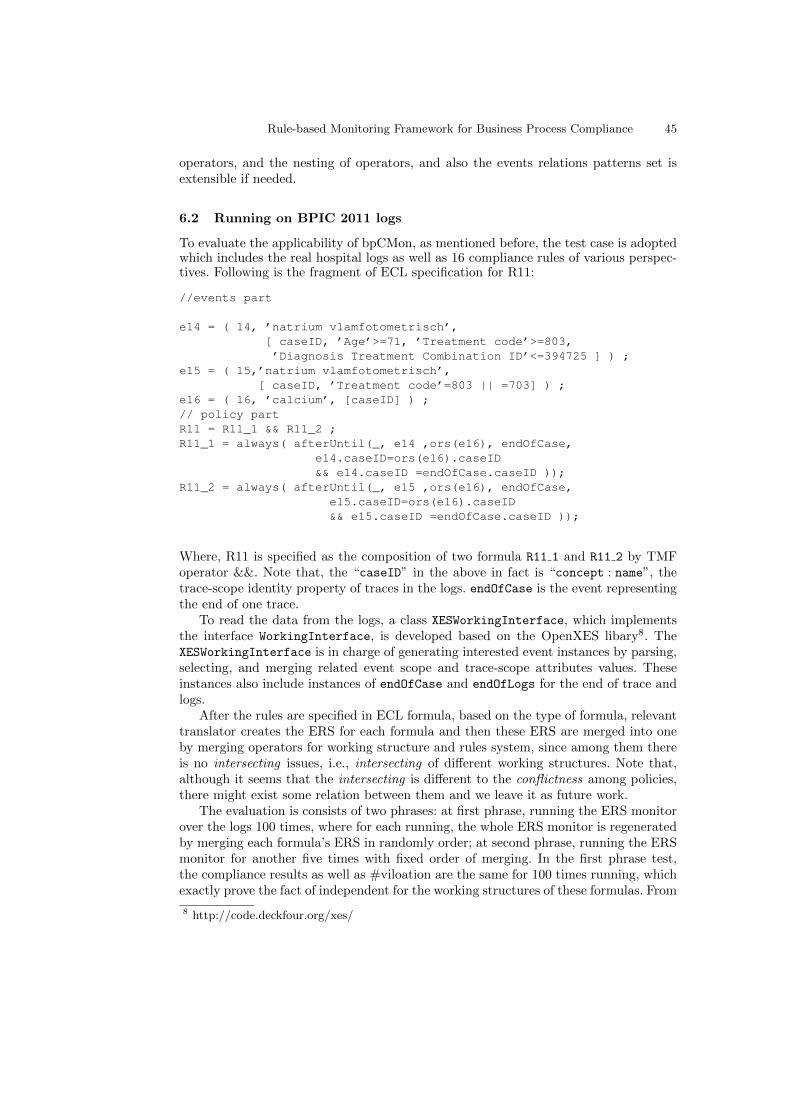
Rule-based Monitoring Framework for Business Process Compliance 45
operators, and the nesting of operators, and also the events relations patterns set isextensible if needed.
6.2 Running on BPIC 2011 logs
To evaluate the applicability of bpCMon, as mentioned before, the test case is adoptedwhich includes the real hospital logs as well as 16 compliance rules of various perspec-tives. Following is the fragment of ECL specification for R11:
//events part
e14 = ( 14, ’natrium vlamfotometrisch’,[ caseID, ’Age’>=71, ’Treatment code’>=803,’Diagnosis Treatment Combination ID’<=394725 ] ) ;
e15 = ( 15,’natrium vlamfotometrisch’,[ caseID, ’Treatment code’=803 || =703] ) ;
e16 = ( 16, ’calcium’, [caseID] ) ;// policy partR11 = R11_1 && R11_2 ;R11_1 = always( afterUntil(_, e14 ,ors(e16), endOfCase,
e14.caseID=ors(e16).caseID&& e14.caseID =endOfCase.caseID ));
R11_2 = always( afterUntil(_, e15 ,ors(e16), endOfCase,e15.caseID=ors(e16).caseID&& e15.caseID =endOfCase.caseID ));
Where, R11 is specified as the composition of two formula R11 1 and R11 2 by TMFoperator &&. Note that, the “caseID” in the above in fact is “concept : name”, thetrace-scope identity property of traces in the logs. endOfCase is the event representingthe end of one trace.
To read the data from the logs, a class XESWorkingInterface, which implementsthe interface WorkingInterface, is developed based on the OpenXES libary8. TheXESWorkingInterface is in charge of generating interested event instances by parsing,selecting, and merging related event scope and trace-scope attributes values. Theseinstances also include instances of endOfCase and endOfLogs for the end of trace andlogs.
After the rules are specified in ECL formula, based on the type of formula, relevanttranslator creates the ERS for each formula and then these ERS are merged into oneby merging operators for working structure and rules system, since among them thereis no intersecting issues, i.e., intersecting of different working structures. Note that,although it seems that the intersecting is different to the conflictness among policies,there might exist some relation between them and we leave it as future work.
The evaluation is consists of two phrases: at first phrase, running the ERS monitorover the logs 100 times, where for each running, the whole ERS monitor is regeneratedby merging each formula’s ERS in randomly order; at second phrase, running the ERSmonitor for another five times with fixed order of merging. In the first phrase test,the compliance results as well as #viloation are the same for 100 times running, whichexactly prove the fact of independent for the working structures of these formulas. From
8 http://code.deckfour.org/xes/

46 Ping Gong, David Knuplesch, and Manfred Reichert
Table 3, it is known that, among 16 rules, the logs is compliant with five rules, R4, R7,R13, R15, R16, and for other rules, there are various violations. For the violation, theERS monitor provides useful feedbacks as following two samples:BEFORE-VIOLATE-TYPE for policy 1: no event 5 is happened before event instance(caseid=00000388,
eID= 1, name= administratief tarief - eerste pol, pId= null, at=01:00:00 09/05/2005 ) in given time with
given condition !
AFTER-VIOLATE-TYPE for policy 3: no event 13 is happened after event instance(caseid=00000830, eID=
4, name= aanname laboratoriumonderzoek, at=00:00:00 03/03/2008 ) in given time with given condition !
For the running cost, it mainly consists of two parts: for ERS monitor running andfor OpenXES caching all the event instances. From Table 4, the number of involvedevent patterns is 21 and the total of violations is 4937, and for the running cost, ERSis of practical efficient. Note that, the symbol “/” in the table is used to delimit thecost for ERS monitor (at the front) and OpenXES file caching (at the behind).
As for the performances of ERS monitor, the event features and reaction ruleslength would be the main influencing factors. Event features here refer to the eventstructure property and the sub-event relation among events. If the event consists ofcomplex attributes constraints or there exist couples of events with sub-event relation,then the cost of event matching as well as reaction would be increased. In this testcase, there are three pairs of events with sub-event relation. As for the memory costof ERS monitor, it might be related to the working manner of OpenXES: loading allthe data from logs file into the memory and then the data available for use. After dataloaded, there is the overhead of memory for ERS ranged from 8% to 20%.
Table 3. Violations for incom-pliant rules
rule #violationR1 805R2 1R3 30R5 593R6 1833R8 1R9 798R11 8R12 45R14 823
Table 4. Performance of bpCMon monitor for theBPIC2011 hospital logs
rules #event #viol. time(sec) memory(mb)
R1-R16 21 4937
5.39/5.49 378.3/350.204.936/5.492 326.8/294.595.143/5.406 377.53/335.195.361/5.648 293.69/240.185.370/5.471 383.51/328.45
6.3 The efficiency of bpCMon-Monitor
In this subsection, the efficiency of bpCMon monitor will be evaluated by two testcases: one is adopted from [21], wherein, the compliance rules and logs are concerningwith resources granting and releasing for the tasks of planetary rover; the other is frombanking setting and created based on [10].
TestCase1. (Release) A resource granted to a task should eventually be releasedby that task ;(NoRelease) A resource can only be released by a task, if it has been granted to thattask, and not yet released;

Rule-based Monitoring Framework for Business Process Compliance 47
(NoGrant) As long as a resource is granted to a task, it can not be granted, neitherto that task nor to any other task.
Within these rules, there are mainly two events, grant(s, t , r) and release(s, t , r),which represent “task t is granted/released resource r at timestamp s” respectively. Thetesting logs is created exactly following the same procedure in [21]. The logs creating iscontrolled by three parameters (G, L, R): the head and tail part are the grant instanceswith the same number controlled by G, and the middle part is consisted of L groupsof R pairs of release and grant instances. Furthermore, the created logs has instancesnumber determined by 2×(G + L× R) and also satisfies that, if G ≥ R, the logs wouldbe compliant, otherwise, the violation number is determined by 2× (R −G).
0 4 8 1 2 1 60
2 0
4 0
6 0
8 0
1 0 0
1 2 0
1 4 0
1 6 0
time(s
ec)
l e n g t h ( m )
D r o o l s b p C M o n M o p
Fig. 4. The time costs for Drools, MOP, and bpCMon running over TestCase 1.
To compare bpCMon monitor, three related works 9 are adopted: the first is MOP,which is known as fastest monitor for Java programs in runtime verification community,and the second is Drools, which is the state-of-art rule-based inference engine, and thelast one is MonPoly, which supports monitoring the metric linar temporal logic and theaggregation extension as well. The comparing is separated into two groups since theirdifferent running requirements: (MOP, Drools, bpCMon) and (MonPoly, bpCMon).
For the first group, the comparing is performed over six logs with instances numberranged from 1 millon to 16 millon. Before starting the comparison, for MOP, themonitor should be generated by running rv -monitor over the .rvm file which specifiesabove rules as a finite state machine; for Drools, a kie-session should be gotten first fromthe .drl file which describe the above rules as drools rules; and for bpCMon, the monitoris generated from the ECL specification of above rules. After these preparations, foreach logs, each subject sequently runs three times over the logs by reacting on theevent instance one by one through the related logs reader, meanwhile, for each runningthe maximal memory is recorded as well as its spent time. Note that, the time costsfor logs reader initializing and closing are excluded from the spent time. The runningdata are listed in Table 5 and also the spent time comparing w.r.t. the length of logsis depicted as Figure4.
9 MOP with version 4.0.0, Drools with 6.3.0, and MonPoly with 1.1.6.

48 Ping Gong, David Knuplesch, and Manfred Reichert
Table 5. The performances of Drools, MOP, and bpCMon for running over TestCase 1.
NO 1 2 3 4 5 6
Type (5k, 5k, 100) (30, 100k, 10) (1, 1m, 1) (2, 1m, 2) (5, 1m, 5) (10, 1m, 8)Length 1,010,000 2,000,060 2,000,002 4,000,004 10,000,010 16,000,020
Drools(time sec)
10.492 16.845 17.081 33.226 85.285 145.20110.18 17.451 17.27 33.406 87.521 149.4910.274 18.271 17.06 34.69 86.578 152.249
MOP(time sec)
4.07 5.137 4.977 8.91 20.718 31.1734.093 5.299 4.77 8.95 19.858 31.854.341 5.308 4.84 8.714 19.676 32.467
bpCMon(time sec)
4.916 6.919 7.641 13.851 30.607 47.9475.014 7.679 7.944 13.482 30.948 47.8775.205 7.802 7.976 13.52 31.167 48.611
Drools(memory MB)
132.13 678.95 741.02 864.35 1155.7 1435.5420.53 740.88 629.25 800.52 1135.6 1420.9396.28 723.38 583.11 746.60 1097.8 1464.5
MOP(memory MB)
310.47 274.84 402.77 169.14 529.39 620.6392.52 425.8 441.25 194.50 542.9 617.0456.14 531.67 482.47 274.94 555.3 604.3
bpCMon(memory MB)
284.12 215.81 355.42 297.74 483.94 575.32419.67 406.07 503.31 517.47 515.07 612.8467.07 557.74 576.52 534.9 500.2 623.6
For the second group, five logs are used with lengths ranged from 1 million to 8millon. The testing is conducted over the same laptop but on its VMware workstationwith Fedora Linux 20 setting maximal memory to 3.8G, and bpCMon runs on theEclipse of Mars version 4.5.0 with JDK1.8. The comparing is performed similarly tothe first group, except the recorded running time including additional costs for fileintializing and closing. The running data are listed as Table 6 and their time costs aredrawed as Figure 5.
From Tables 5, 6 and Figures 4, 5, it shall be seen that, in this test case, bothof the MOP and bpCMon outperform the Drools; the bpCMon peforms better thanthe MonPoly based on the consumed time and memories; and also the bpCMon iscomparable to MOP, although there is some unstable in the memory consuption 10
might because of the garbage collecting of JVM.
Drools has its strength in finding fireable rules among large numbers of rules byusing of net-based working memory. However, in monitoring setting, the solution forthe issue, i.e., how to quickly find some target when some trigger occurs, is one ofessential factors influencing the efficiency of monitor. For MOP, the solution is byparameterized indexing and the target is related state machinethe for the trigger; andfor the bpCMon, thanks to the working structure which speeds up finding the storedtarget by the indexing relation between trigger and target. For the Drools, althoughthere are also indexes in different types of node memories, additional time and memorymight be needed because of its manner for dealing with the matched event instance:every matched instance needs to be stored firstly in related Alpha memory and thenprocessing its influence on other related nodes. Considering the release rule, whena release instance occurs, to check whether there is related grant instance occurredbefore, it would be enough to simply check the state of related state machines forMOP and the related queue for bpCMon by parameters of release instance. However,in Drools, the release instance would be stored first and then deleted after processed,
10 In the testing, the VisualVM 1.3.8 plugin is used to monitor and measure the memoryconsuming: https://visualvm.java.net/.

Rule-based Monitoring Framework for Business Process Compliance 49
which might undermine the efficiency no matter in time or memory consuming. For theMonPoly, its analysis is based on formula rewritting rules and its running performanceis very sensitive to the time points range, however, it is unclear whether there are someindexing structures for organizing related data or memory optimizing techniques.
Table 6. The performances of MonPoly and bpCMon for running over TestCase 1.
NO 1 2 3 4 5
Type (5k, 5k, 100) (1, 1m, 1) (2, 1m, 2) (2, 1m, 3) (2, 1m, 4)Length 1,010,000 2,000,002 4,000,004 6,000,004 8,000,004
MonPoly(time sec)
9.245 14.936 29.723 44.481 58.6448.865 14.557 28.828 43.541 58.5408.898 14.285 28.490 44.481 58.458
bpCMon(time sec)
5.308 8.084 15.426 21.744 27.7785.234 8.014 15.394 21.349 27.7164.945 7.759 14.713 21.744 27.338
MonPoly(memory MB)
433.072 442.260 826.980 904.480 1568.368
bpCMon(memory MB)
301.470 200.508 300.423 311.377 283.947303.764 266.052 303.355 321.671 302.657317.462 290.365 321.767 324.052 330.859
For the bpCMon, it is the indexing based working structure which enables bpCMonattain time efficiency; and for saving the memory consuption, each storing queues inbpCMon just keep the reference to the matched instance object, which is designed basedon the fact: for each occurred instance as a fact, it can be assessed but unchangable.Although in the test case, MOP is more efficient then bpCMon, however, it can not yetsupport the compliance rules with metric time and data aggregation, e.g., the followingtest case 2.
0 2 4 6 80
2 0
4 0
6 0
time(S
ec)
l e n g t h ( M )
M o n P o l y b p C M o n
Fig. 5. The time costs for MonPoly andbpCMon running over TestCase 1.
0 1 2 3 4 5 60
5 0
1 0 0
1 5 0
2 0 0
2 5 0
3 0 0
3 5 0
4 0 0
Time(s
ec)
L e n g t h ( M )
M o n P o l y b p C M o n
Fig. 6. The time costs for MonPoly andbpCMon running over TestCase 2.
TestCase2. For each user, the number of peaks over the last 30 days does notexceed a threshold of 5, where a peak is a value at least twice the average over sometime window(here 30 days).
The test logs is generated based on parameters, #U , the number of user, #EP ,the number of events for each user per time point, and #R, the time point range. The

50 Ping Gong, David Knuplesch, and Manfred Reichert
syntheising process is similar to [10]: setting #U to 100, #EP to 5, and #R from 800to 10000, then in each time point, for each user generate 5 withdraw event instances ofthe form: (ts,′ withdraw ′, userID , amount), where ts is the time stamp for the instance,userID orderly selected from [1, 100], and amount is set as a constant11, and then,write all of these instances into the given file with their generated order. Note that, thetime window(30 days) in the test case is set as 30 seconds. In this way, 7 test logs aregenerated with the length ranged from 400 thousand to 5 million.
The testing consists of 7 groups and within each group, the MonPoly and bpCMonrun sequencely for the same logs. For each running, the monitors react on the instancesparsed by relevant reader from the logs, and during the running the spent time wasrecorded and also the result was checked. For each group testing, the MonPloy doesnot response counter-example and also bpCMon reports compliant results. Their spenttimes are drawed as Figure 6. From the figure, it shall be seen that, such compliancerule is of expensive time consuming for both monitors, and their performances are notdistinct too much for the logs with length within 1 million, but after that, since thest+tree structure, bpCMon monitor attains minor better scalability than the MonPolywhich has the additional time overhead from 15% to 21% as the logs lengths increasedfrom 2 to 5 million.
7 Related works
Basically, no matter what kind of monitoring, it includes the contents of three aspects:the subject to be monitored, the objective for monitoring, and the technique used bymonitoring for making decision. Compliance monitoring aims at understanding therelation between behaviors of business processes and compliance rules. Currently, thereis a plethora of related works addressing similar objectives but with different subjects.
7.1 Business processes compliance monitoring
The works in this category share the same objective and subject with this work, butwith different compliance languages of various epxressive and monitoring mechanisms.
The work [24] proposed a metamodel REALEM for specifying compliance rules.The metamodel includes three parts: types model, three compliance rule patterns, andmeta information. Based on events model and events correlating, the compliance rulesare translated into executable rules on IBM infrastructures. As for the three patterns,e.g., x AtLeast(c) Before y , they are in fact corresponding to before and after patternsin ECL. In work [12], the graphic language Declare is used as compliance/processesconstraints specification language. After translated the Declare to LTL, the monitoris created based on colored automata. The weakness of this work is the limitationof Declare which only supports control-flow perspective. In work [15], Declare is ex-tended to support metric time and life-cycle for activity element and also providedwith monitoring semantics based on event calculus formalism. Although the formal-ism is powerful, the extended Declare still supports less for the data perspective. In
11 Such setting would make the logs compliant with the rule, which enables MonPoly andbpCMon compare the efficiency; Otherwise, if set the amount randomly, it would be unrea-sonable for the comparing, since their different ways to response the violation, i.e., MonPolyprints all the violations and bpCMon stores them in the container.

Rule-based Monitoring Framework for Business Process Compliance 51
work [13], it proposed the Linear Dynamics Logic(LDL), which the integration of LTLand regular expression, as well as its monitoring semantics. The LDL enable to spec-ify the compensation for some condition occurring. However, it is still theoretic workand without evaluation performance data. Works of [8][9] proposed compliance graphlanguages CRG and eCRG , where eCRG extended from CRG to support data and re-source perspectives. For the monitoring algorithm, both works adopted marking basedapproach, which is a natural way for the graph language to describe the state of com-pliance rule. In addition, by graph marking, it is also possible to provide root causesfor the violations. However, currently eCRG can not support data aggregation and alsolack of performance data.
7.2 Business process execution monitoring
Although the works in category share the same subject with our work, they havedifferent objectives as well as the used techniques. Process execution monitoring is closerelated to business activity monitoring(BAM), it typically includes filtering, correlating,aggregating, and reporting the data related to some PKIs [2] by proper CEP engine [25];
Work [26] proposes an approach which beak the activities into event trails and thentranslate compliance rules into CEP rules based on these event trails. By using theCEP engine, the compliance can be checked and responded. But it is not clear whatkind of compliance rule this method can address. Furthermore, their extending work [7]proposes a model-driven method, which includes an Domain-specific Language basedon control-flow occurrence patterns, and also the translations from DSLs to the codesused by specific CEP engine. The drawbacks are the limited expressive of DSLs andthe relative limited abilities of CEP to support stateful compliance monitoring.
The work [27] consider the compliance between business process execution withprocess profile by using CEP. Three basic casual constraints are considered, strict order,exclusive, and interleving, and further translated into CEP queries. By filtering andaggregating events, the violations are reported. Work [28] considers the business processmonitoring issue, where the events are related to activity life-cycle and business processis enriched with process event monitoring points. By process models decompositiontechnique, the process model is transformed into CEP queries. Work [29]propose aframework, named as aPro, which is by evaluating the KPI metrics to understand thebusiness and compliance situations. To evaluate such KPIs, related measure pointsshould be defined first and annotated into the process models. During the processesexecution, the related measures data are collected and correlated, and analysis byusing of CEP technique. Based on such measures, the regular KPIs and aggregatingKPIs are evaluated and then the goals fulfillments are valuated. The key challengesfor such methods are how to define relevent KPIs and their related measuring points.Furthermore, it is unclear about how to support temporal compliance rules.
7.3 Services-based system monitoring
The subject of this kind of monitoring is Services-based system and its first class citizenis the messages among services. Comparing to this work, this kind of monitorings havesimilar objective and also overlapped monitoring mechanisms.
The objective of the monitoring in [30] is to understand the relation between theinteractions specified in BPEL and the policies by proposing instance monitor and

52 Ping Gong, David Knuplesch, and Manfred Reichert
class monitor. The policy language is message-based and devised based on PastLTL,and also enables to specify properties of counting based aggregation and staying basedtime. However, this language still not powerful enough for supporting after-type andmetric time policies. Also, the monitor has no root-cause analysis for the violations.Work [31] proposed the method for detecting semantically-upgraded complex eventsby making use of semantic ontology during the execution of semantic web servicescomposition. However, the objective of this work is different to processes compliancemonitoring.
The work [32] proposed a multi-level monitoring framework, named as SERMON, toaddress the compliance of service agents behaviours with their commitment protocolswhich are specified with Communicative Act extended Object Constraint Language.The work is the extension of their prior work on requirement monitoring REQMON [33]and the facility used for monitoring is rule based engine Jess.
To enforce the data-aware message contracts for the web services, the work [34] pro-posed an specification language LTL-FO+, extending from LTL by introducing basedon quantifier and XPath an new construct to quantify the data inside the message. Themonitoring algorithm for LTL-FO+ formula is designed based on a finite state machinevariant, called watcher, which is created on the fly to avoid the huge state space andthe state transition is based on formula structure. Regrading to the data-aware con-tracts, the ECL is also enable to cope with based on event attributes as well as eventscorrelating, furthermore, ECL also support data aggregation which is out of scope ofLTL-FO+.
7.4 Runtime verification
The program is the main subject of runtime verification, but it has similar objectiveand monitoring mechanisms with process compliance monitoring.
The Java-MaC [35] is a prototype implementation of the monitoring and checkingarchitecture for Java programs. From the specification view, it consists of two levelslanguages, PEDL, for low level event definition and as well as high level events defini-tions based on low level ones; MEDL is used to describe the property based on highlevel events. From such two specifications, the filter, event regnizer, and checker can becreated automatically. The filter is probed into java codes and send related messagesto regnizer to import high level events for checking.
The work [36] compared three typical monitoring approaches regarding to finitestate properties, i.e., object-based, state-based, and symbol based, to investigate theirrelative strengths and weaknesses. By experiments, the object-based has little over-head for multi state changes in property comparing to the other, however, suffers muchoverhead when the loops within properties. The other two seems exactly converse tothe object-based. The work [37] extends the parametric trace slicing method to over-come the weakness of dealing with the operating data and universal of parameters,by proposing the quantified event automata. However, although automata is powerful,lots of works are still needed for specification language and evaluations.
The work [21] implements a rule system based runtime engine, i.e., LOGFIRE, byremifying RETE algorithm. The refimications include introducing the double-indexingamong related nodes for speeding up tokens’ matching. However, once some fact in thenode was updated, each related nodes as well as the indexing mappings would need tobe updated synchronizedly. It thereby might be the factor of undermining the efficiency.

Rule-based Monitoring Framework for Business Process Compliance 53
In this paper, the tree-like indexing structure is more simple, flexible, and independent.For each fact in value structure, after used, it can be deleted without any influences onothers. Besides, from the specification aspect, the supports in [21] for high level, e.g.,temporal order, is still limited to two basic patterns.
7.5 Discussions
From the views of the specification language and monitoring mechanism, the relationswith closely existed works need to be further clarified to promote the distinct featuresas well as behind designing principles for the bpCMon.
(1) the relation between MLTL/LTL and ECL.From the expressive aspect, except aggregating part, ECL formula could be de-
scribed in MLTL/LTL. However, ECL is more abstract than MLTL/LTL, and is specif-ically designed for compliance monitoring based on the signature including events andevent-relation patterns. Within the ECL formula, it includes the monitoring featuredelements: trigger , decider , and events correlating , which are essential and also prop-erly organized for creating ERS and efficient monitoring afterwards. These points arenot easy to be attained by directly using MLTL/LTL. Besides, MLTL/LTL does notdirectly support specifying the compliance rule of data aggregation.
(2) the distinct features of ERSERS is a light-weight rules engine and designed specifically for reactive monitoring.
Its distinct features come from two aspects: the rule form and working structure. For therule form ,as mentioned before, the rules of ERS are of the form, trigger → c reaction.Comparing to classic rule form, e.g., event-condition → action [21], the characters ofERS rule form could speed up finding fireable rules and condition evaluation, and alsoavoid the issue about fact staying around [21] for generic rule engine, e.g., Drools.For the working structure, it is a tree like structure distributed and equipped withindexing structure for each independent storing, which is different to the net like andnode sharing structure of RETE-based rules system. Such working memory has itsstrength for the case of numbers of rules overlapped their left hands. However, for themonitoring, as indicated in the experiment, ERS working structure is more efficient.
(3) dealing with memory consuming for ERSIn fact, in bpCMon, time interval plays an important role in reducing memory
consuming through the bounded data queue. More specifically, once the instance is outof date comparing the new added one, it would be deleted from the queue. Besides that,the principle, ”abandon it after it used”, is adopted to apply to each reaction. i.e., foreach instances in the afterIIS structures, after it was assessed and used, it would bedeleted at once from the queue. In addition, as mentioned before, each storing queuesin bpCMon just keep the reference, instead of the clones , of the matched instanceobject, which can also effectively save the memory consumption. Furthermore, fromthe programming technique view, garbage collecting and using weak reference objectinstead of strong reference object, are also some future options for further reducingmemory like [37].
8 Conclusion and future works
To target at specifying complex compliance rules as well as their monitoring, thiswork presents the business processes compliance monitoring framework, bpCMon. It

54 Ping Gong, David Knuplesch, and Manfred Reichert
mainly consists of: an event-pattern based compliance language(ECL) for specifyingcompliance rules, and events indexed reaction system (ERS) as engine for compliancemonitoring. The ECL is devised based on event-pattern and events relation patterns,and also featured with aggregating operators; ERS is a powerful rule based system anddesigned based on events indexing structure. Experiments on a real life hospital logsover 16 compliance rules indicate the applicability of bpCMon; and the comparisonswith two known related works, the MOP and Drools, over the benchmark demonstratethe efficiency of bpCMon; and furthermore the data aggregation functionals of bpCMonis also evaluated by test case.
As for the future works, from the practical view, a friendly interface is needed tosupport users specifying and managing their compliance rules; from the theoreticalview, it is also important to further devise the methods to resolve the rules conflictissue and the intersecting of working structures as well as their possible relations. Infact, such solutions would be the basis for targeting at the scalable issue of the bpCMonwhen considering huge number of rules. Finally, further evaluations are also needed forthe soundness of the bpCMon.
References
1. Sadiq, S.: A roadmap for research in business process compliance. In: W. Abramowicz, L.Maciaszek, K. Wecel (Eds.) BIS 2011 Workshps, LNBIP 97, pp. 1-4 (2011)
2. Rademakers, T.: Activiti in action. Manning publications(2012)3. Breaux, T.D., Antn, A. I., and Doyle, J.: Semantic parameterization:a process for modeling
domain descriptions. ACM Transations oon Software Enginnering and Methodology, Vol.18, No.2 (2008)
4. Pesic M. and Van der Aalst W.M.P.: A declarative approach for flexible business processesmanagement. In: J. Eder, S. Dustdar et al.(Eds. ): BPM 2006 Workshops, LNCS 4103,pp.169-180 (2006)
5. Awad A., Weidlich M., and Weske M.: Visually specifying compliance rules and explainingtheir violations for business processes. J. Visual Languages and Computing. 22(2011), pp.30–55 (2011)
6. Elgammal A., Turetken O., van den Heuvel W.: Formalizing and appling compliance pat-terns for business process compliance. Software & Systems Modeling, pp 1-28 (2014)
7. Mulo, E., Zdun, U., and Dustdar, S.: Damain-specific language for event-based compliancemonitoring in process-driven SOAs. In: SOCA (2013) 7: 59-73 (2013)
8. Ly L.T., Rinderle-Ma S., Knuplesch D., and Dadam P.: Monitoring business process com-pliance using compliance rule graphs, In: R. Meersman, T.Dillon, and P. Herrero(Eds.):OTM 2011, Part I, LNCS 7044, pp. 82-99 (2011)
9. Knuplesch D., Reichert M., and Kumar A.: Visually monitoring multiple perspectives ofbusiness process compliance. In: Hamid, R. M. N., Jan, R., and Matthias, W.(Eds.), BPM2015. LNCS 9253, pp. 263-279 (2015)
10. Basin D., Klaedtke F., Mller S, etc.: Monitoring of temporal first order properties withaggregations. In: proceeding of RV 2013, LNCS 8174, pp. 40-58 (2013)
11. Dwyer, M.B., Avrunin, G.S., Corbett, J.C.: Patterns property specifications for finite-stateverification. In: ICSE 99, Los Angeles CA, ACM, pp. 411-420 (1999)
12. Maggi F.M., Montali M., Westergaard M., Van der Aalst W.M.P.: Monitoring busi-ness constraints with linear temporal logic: An approach based on colored automata. In:S.Rinderle-Ma, F. Toumani, and K. Wolf(Eds.) BPM 2011, LNCS 6896, pp. 132–147 (2011)
13. Giacomo G., Masellis R.D., Grasso M., Maggi M.F., and Montali M.: Monitoring businessmetaconstraints based on LTL and LDL for finite traces. In: Shazia W. S., Pnina S., HagenV.(Eds.) BPM 2014. pp. 1–17 (2014)

Rule-based Monitoring Framework for Business Process Compliance 55
14. Basin D., Klaedtke F., Mller S., and Zlinescu E.: Monitoring metric first-order temporalproperties. In: Journal of ACM, 62(2), pp:1-38 (2015)
15. Montali M., Maggi M.F., Chesani F., Mello P., and Van der Aalst W.M.P.: Monitoringbusiness constraints with the event calculus. ACM Transactions on Embedded ComputingSystems, Vol.9, No. 4, 1-29 (2010)
16. Chen F., Jin D., Meredith P.O.N., and Rou G.: Efficient formalism-independent monitor-ing of parametric properties. In: ASE 2009, IEEE press, pp. 383-394 (2009)
17. Charles L. Forgy.: Rete: a fast algorithm for the many pattern/many object pattern matchproblem. In: Artificial Intelligence 19(1982), pp. 17-37 (1982)
18. Drools:http://docs.jboss.org/drools/release/6.3.0.Final/drools-docs/html_single/index.html (2015)
19. Friedman-Hill E.: Jess in action: Rule based systems in Java. Manning publications. (2003)20. Ly L.T., Maggi F.M., Montali M., Rinderle-Ma S., van der Aalst W.M.P.: Compliance
monitoring in business processes: functionalities, application, and tool-support. InformationSystems. 54, 209–234 (2015)
21. Havelund K.: Rule-based runtime verification revisited. In: Journal of Software ToolsTechnology Transfer, 17:143-170 (2015)
22. Gnther C.W., and Werbeek E.: XES standard definition. In http://www.xes-standard.org/_media/xes/xesstandarddefinition-2.0.pdf, March 28,version 2.0 (2014)
23. Turetken O., Elgammal, A., and van den Heuvel W.J.: Capturing compliance require-ments: a pattern-based approach. IEEE Software, IEEE Computer Society (2012)
24. Giblin, C., Muller, S., Pfitzmann, B.: From regulatory policies to event monitoring rules:towards model-driven compliance automation. Technical report RZ3662, IBM Research.(2006)
25. Esper: http://www.espertech.com/index.php (2015)26. Mulo, E., Zdun, U., and Dustdar, S.: Monitoring web service event trails for business
compliance. In: IEEE International Conference on Service-oriented Computing and Appli-cations(SOCA), IEEE, 2009.
27. Weidlich M., Ziekow H., Mendling J., Gunther O., Weske M., and Desai N.: Event-based monitoring of process execution violations. In: S. Rinderle-Ma, F. Toumani, andK. Wolf(Eds.) BPM 2011, LNCS 6896, pp.182-198 (2011)
28. Backmann, M., Baumgrass, A., and Herzberg, N.: Model-driven event query generationfor business process monitoring. In: A.R. Lomuscio et al. (Eds.): ICSOC 2013 Workshops,LNCS 8377, pp.406-418 (2014)
29. Koetter, F., and Kochanowski, M.: A model-driven approach for event-based business pro-cess monitoring. In: Information Systems and e-Business Managmement, Springer-Verlag,vol 13, issue 1, pp. 5-36 (2015)
30. Barbon, F., Traverso, P., Pistore, M., and Trainotti, M.: Run-time monitoring of in-stances and classes of web service compositions. In: IEEE Inernational Conference on WebServices(ICWS’06), IEEE computer society. (2006)
31. Vaculin, R., and Sycara, K.: Specifying and monitoring composite events for semantic webservices. In: Fifth European Conference on Web Services. (2007)
32. Robinson W.N., and Purao S.: Monitoring service systems from a language-action per-pective. In: IEEE transactions on services computing, Vol. 4, No, 1. pp. 17-30 (2011)
33. Robison W.N.: A requirements monitoring framework for enterprise systems.In: Require-ments Engineering, 11:17-41 (2006).
34. Hall S., and Villemaire R.: Runtime enforcement of web service message contracts withdata. In: IEEE transations on services computing, vol 5, vol 2. pp. 192-206 (2012)
35. Kim M., Kannan S., Lee I., and Sokolsky O.: Java-Mac: a run-time assurance approachfor java programs. In: Formal Methods in System Design. 24(2), pp 129-155 (2004)
36. Purandare R., Dwyer M.B., and Elbaum S.: Monitoring finite state properties: algorithmicapproaches and their relative strengths. In: S. Khurshid and K. Sen (Eds.): RV 2011, LNCS7186, pp. 381-395 (2012)

56 Ping Gong, David Knuplesch, and Manfred Reichert
37. Luo Q., Zhang Y., Lee C., Jin D., Rou G., et al.: RV-Monitor: efficient parametric runtimeverification with simultaneous properties. In: B. Bonakdarpour and S.A. Smolka(Eds.): RV2014, LNCS 8734, pp. 285-300 (2014)
38. Havelund K., and Joshi R.: Experience with rule-based anaysis of spacecraft logs. In: C.Artho and P.C.Olveczky(Eds.): FTSCS 2014, CCIS 476, pp. 1–16 (2015)
39. Barringer H., Falcone Y., Havelund K., etc.: Quantified event automata: towards expres-sive and efficent runtime monitors. In: D. Giannakopoulou, and D. Mery(Eds.): FM 2012,LNCS 7436, pp. 68-84 (2012)
40. Datar M., Gionis A., Indyk P., and Motwani R.: Maintaining stream statistics over slidingwindows. In: SIAM J. COMPUT. 31(6), pp. 1794-1813 (2002)
41. Basin, D., Klaedtke, F. and Zlinescu E.: Greedily computing associative aggregations onsliding windows. In: Information Processing Letters, elsvier, 115(2), pp. 186-192 (2015)


Ulmer Informatik-Berichte ISSN 0939-5091 Herausgeber: Universität Ulm Fakultät für Ingenieurwissenschaften, Informatik und Psychologie 89069 Ulm