Embed Size (px)
Citation preview
Conference Paper, Published Version
Ruggeri, F.; Watai, R. A.; Tannuri, E. A.Passing Ships Interaction in the Oil Terminal of SãoSebastião (Brazil): An Applied Study to Define theOperational LimitsZur Verfügung gestellt in Kooperation mit/Provided in Cooperation with:Flanders Hydraulics Research, Ghent University, Maritime Technology
Verfügbar unter/Available at: https://hdl.handle.net/20.500.11970/99864
Vorgeschlagene Zitierweise/Suggested citation:Ruggeri, F.; Watai, R. A.; Tannuri, E. A. (2016): Passing Ships Interaction in the Oil Terminalof São Sebastião (Brazil): An Applied Study to Define the Operational Limits. In: Uliczka,Klemens; Böttner, Carl-Uwe; Kastens, Marko; Eloot, Katrien; Delefortrie, Guillaume;Vantorre, Marc; Candries, Maxim; Lataire, Evert (Hg.): 4th MASHCON - InternationalConference on Ship Manoeuvring in Shallow and Confined Water with Special Focus on ShipBottom Interaction. Karlsruhe: Bundesanstalt für Wasserbau. S. 168-176.https://dx.doi.org/10.18451/978-3-939230-38-0_21.
Standardnutzungsbedingungen/Terms of Use:
Die Dokumente in HENRY stehen unter der Creative Commons Lizenz CC BY 4.0, sofern keine abweichendenNutzungsbedingungen getroffen wurden. Damit ist sowohl die kommerzielle Nutzung als auch das Teilen, dieWeiterbearbeitung und Speicherung erlaubt. Das Verwenden und das Bearbeiten stehen unter der Bedingung derNamensnennung. Im Einzelfall kann eine restriktivere Lizenz gelten; dann gelten abweichend von den obigenNutzungsbedingungen die in der dort genannten Lizenz gewährten Nutzungsrechte.
Documents in HENRY are made available under the Creative Commons License CC BY 4.0, if no other license isapplicable. Under CC BY 4.0 commercial use and sharing, remixing, transforming, and building upon the materialof the work is permitted. In some cases a different, more restrictive license may apply; if applicable the terms ofthe restrictive license will be binding.
PASSING SHIPS INTERACTION IN THE OIL TERMINAL OF SÃO SEBASTIÃO (BRAZIL): AN APPLIED STUDY TO DEFINE THE OPERATIONAL LIMITS
F Ruggeri and R A Watai, Argonáutica Engineering & Reseach, Brazil E A Tannuri, Numerical Offshore Tank of the University of São Paulo (TPN-USP), Brazil
SUMMARY
The passing ship effect in a moored vessel is a well-known problem discussed in the literature that involves harbour
operations. The consequences of these interactions are dynamic loads in the mooring system that can exceed the design
values and lead to severe accidents as, for example, the one occurred with the Yusho Regulus and Coal Hunter ships in
Santos port (Brazil). This paper presents the application of a numerical method for the evaluation of mooring loads due
to passing ship problems in São Sebastião port (TEBAR), which is one of the most important oil terminals in Brazil. The
specific operation studied is a Ship-to-Ship transfer considering several vessels (VLCC-VLCC, VLCC-Suezmax), a
condition where no simplified regressions is available to estimate the passing ship forces. Therefore a Rankine Panel
Method (RPM) is applied to evaluate these effects. The forces computed by means of the panel method are applied in the
mooring integrity analysis code (MeDuSa) to verify the maximum loads, which are then compared to design criteria so
as to define the maximum operational conditions. The mooring arrangement, cable properties, fender etc. are determined
by following OCIMF STS recommendations, as well as the Q88 form available for the design vessels.
1 INTRODUCTION
In a near future, the exploration and transportation of
Brazilian pre-salt layer petroleum will demand a large
number of support, transport and offloading vessels in
order to supply all operations, increasing waterway and
port traffic and consequently the chances of berthed ship-
passing-ship interaction events.
Consequently, the berthed ship -passing ship interaction
prediction is very important for the safety of waterways,
port facilities and open sea operations that can be critical
if the ships are sailing close to each other and/or through
a constrained channel, in which wall effects may increase
those interactions, justifying a specific study.
In the past, model scale tests were commonly performed
for estimating the hydrodynamic loads involved in such a
problem. The reference [1] presented an extensive
passing ship experimental campaign in which several
arrangements relating distance, ship size and speed were
investigated. Other experimental results may be found in
[2], [3] and [4], among others. However, this approach is
a very costly way to study the phenomena, especially if
the number of distinct setups/operations is large.
In this sense, some researchers were motivated to create
empirical regressions that can be extended for other
conditions as may be observed, for example, in [4] that
provides expressions for estimating forces and moments
based on model tests data with series 60 ships in shallow
water, which may be useful for simple hand calculations
or for use in spreadsheet predictions. Other empirical
regressions are also proposed in [5] and [6].
Another approach, based on mathematical models, is
presented in [7], which applied the slender body theory
for evaluating the interaction effects involved in the
passing ship problem. This method, however, is limited
to simple and slender hull forms and might not be
properly applied in situations involving large oil carriers,
such as the ones used in Oil & Gas operations.
The advances in computational capability and numerical
methods allowed the continuous improvement of
mathematical models for hydrodynamic problems. The
reference [8] presented calculations considering two
identical and parallel Wigley hulls using RANSE CFD
method (RNG k-ε turbulence model) and compared the
results with the potential flow boundary elements method
(BEM) proposed by [9], demonstrating a good agreement
between both solutions. The reference [10] presented
numerical solutions and validations for conditions
involving non-zero ship drift angle obtained via the CFD
code ReFRESCO and a 3D BEM, in which the authors
conclude that for drift angle higher than 7.5 degrees, the
CFD is a better option to be applied. For zero drift
angles, however, fortunately the 3D BEM is a sufficient
method for the problem, providing efficient solutions in
terms of computational time.
The present paper presents briefly the formulation of the
3D BEM code developed in the Numerical Offshore
Tank of the University of Sao Paulo (TPN-USP) used to
solve the passing ship problem. The code was compared
in [11] to empirical expressions proposed by [4], the strip
body theory method presented by [7] and experimental
data obtained by model tests carried out in the State of
São Paulo Institute for Technological Research (IPT),
presented in [12].
The numerical method is then applied to compute the
hydrodynamic forces in the case of a berthed ship-to-ship
operation in São Sebastião Port (Brazil), one of the most
important oil terminals in Brazil, illustrated in Figure 1.
For this specific operation, no simplified regression is
available considering 3 vessels (2 of them only separated
by pneumatic fenders), and a 3D BEM numerical model
4th MASHCON, Hamburg - Uliczka et al. (eds) - © 2016 Bundesanstalt für Wasserbau ISBN 978-3-939230-38-0 (Online)
DOI: 10.18451/978-3-939230-38-0_21
168
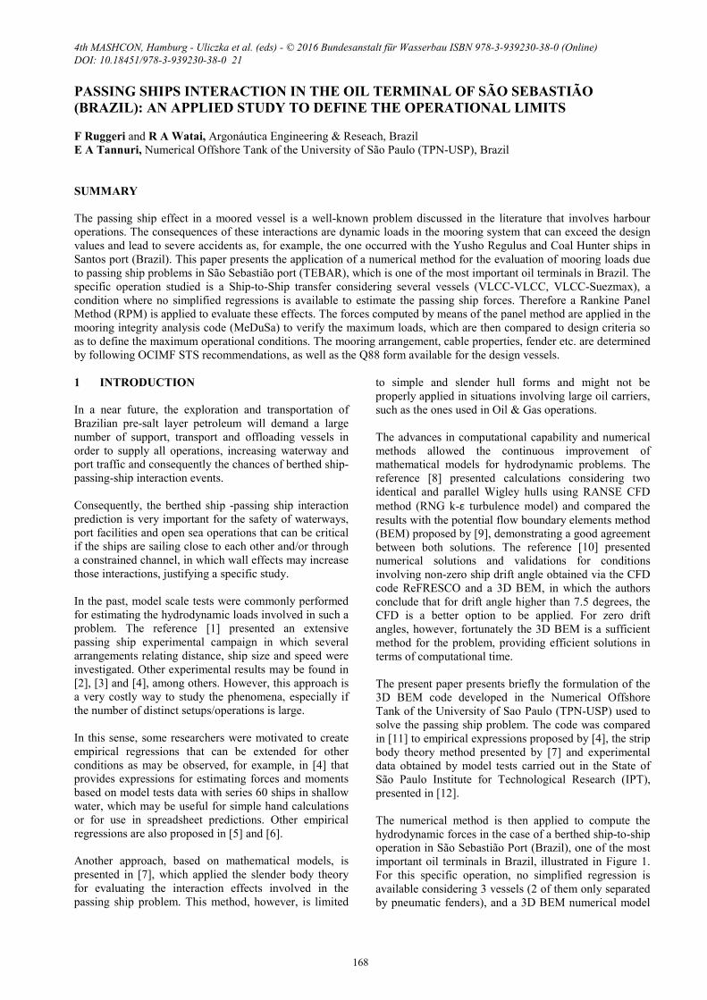
was applied to evaluate the berthed ships - passing ship
interaction forces.
Figure 1. STS operation in the berth and a passing
vessel along the channel
After the hydrodynamic loads are computed in each
vessel, the mooring integrity is evaluated using the
MeDuSa code, also presented, that considers the dynamic
loads due to passing ships, current and wind forces. The
last two forces (current and wind) are computed using
CFD, taking into account the "shadow effect" due to the
proximity of the STS vessels, and providing the forces in
each vessel independetly.
2 MATHEMATICAL MODEL
2.1 HYDRODYNAMIC MODEL FOR THE
CALCULATION OF THE PASSING SHIP
INTERACTION LOADS
The procedure used to estimate the forces and moments
originated by the problem of a ship passing on the side of
a berthed ship may be also treated by means of the
double body potential flow. Under the hypothesis of
incompressible and irrotational flow, and inviscid,
isotropic and homogeneous fluid, the velocity vector
fieldV
is assumed conservative and, therefore, may be
written as the gradient of a scalar potential functionϕ , as
presented in equation (1), therefore the continuous
equation is replaced by the Laplace equation (2) in
volumeΩ .
ϕ∇=V
(1)
02 =∇ ϕ in Ω (2)
Following [13] and [14], the free surface effects were not
considered, since its influence was assumed small upon
the low Froude number values evaluated.
Within this scope, the appropriate boundary conditions
for determining the potential flow are described by the
impermeability condition (3) and (4) on the lateral walls,
bottom and ships wetted surfaces, and a zero flux
equation (5) at the mean water level 0=z , as follows:
0=∂∂
n
ϕ on the captive ship surface, domain
bottom and lateral walls
(3)
nUn
⋅=
∂∂ϕ on the passing ship surface (4)
0=∂∂
z
ϕ at 0=z (5)
where n
and )0,0,( UU −=
are the normal vectors of the
ships wetted surfaces and the ship forward speed vector,
respectively.
Through the use of the Green’s Second Identity, the
volume problem may be rewritten in terms of a boundary
formulation expressed by the second type Fredholm
integral equation (6).
πϕϕϕ2
'
11
'
11=Ω∂
+
∂∂
−∂∂
+∫∫ Ω∂ d
rrnnrr (6)
in which r/1 is the Rankine source and Ω∂ is the
boundary surface. The source image is assumed in order
to avoid the above free surface discretization and
guarantee the no-flux condition in the z=0 plane.
A three-dimensional Boundary Element Method (BEM),
developed in TPN-USP, is then used to solve the
boundary value problem specified. By the use of this
method, the wetted surfaces of the ships, the lateral walls
and the bottom are subdivided into a set of N
quadrilateral panels with N collocation points.
Moreover, the velocity potential, normal vectors etc. are
assumed as constant values over each panel, leading to
the so called Low Order Boundary Elements Method,
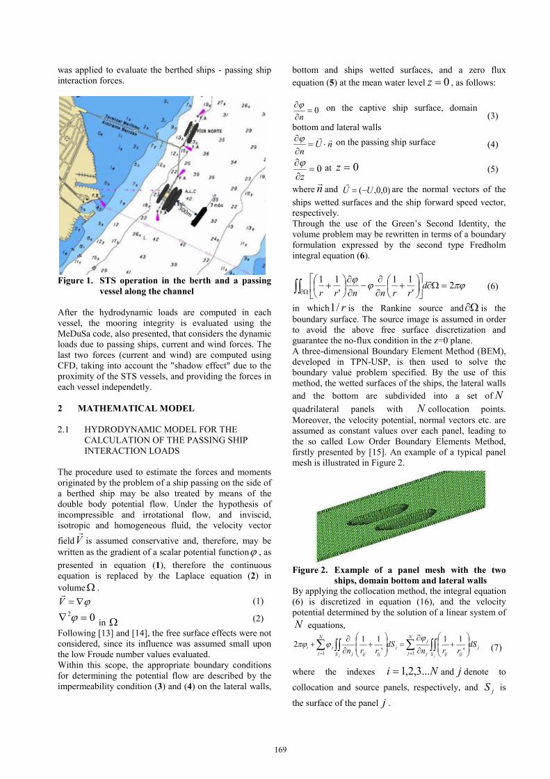
firstly presented by [15]. An example of a typical panel
mesh is illustrated in Figure 2.
Figure 2. Example of a panel mesh with the two
ships, domain bottom and lateral walls By applying the collocation method, the integral equation
(6) is discretized in equation (16), and the velocity
potential determined by the solution of a linear system of
N equations,
j
S ijij
N
j j
j
j
S ijijj
N
j
ji dSrrn
dSrrn
jj
∫∫∑∫∫∑
+
∂
∂=
+
∂∂
+== '
11
'
112
11
ϕϕπϕ
(7)
where the indexes Ni ...3,2,1= and j denote to
collocation and source panels, respectively, and jS is
the surface of the panel j .
169
Once the velocity potentials for each panel of the berthed
ship are determined, the hydrodynamic pressure is
evaluated through the use of the Bernoulli’s equation (8),
in which the time derivative term is evaluated by means
of a centered difference scheme. Notice that the quadratic
velocity term was neglected since the disturbance
velocities were assumed small. The hydrostatic
restoration term is neglected since it is assumed that the
induced roll, pitch and heave are small (which is also in
accordance to the double body model) and it is balanced
by the gravitational forces.
tp
∂∂
−=ϕr
(8)
in which r is the density of water.
Hence, the hydrodynamic forces and moments are
obtained by simply pressure summation over the panel
collection for each body, as presented in expressions (9)
and (10), respectively.
( )jj
N
J
t
j
tt
jt
t
Ant
Fc ∑=
∆+∆+
∆−
−=1
2ϕϕ
r
(9)
( )jjoj
N
J
t
j
tt
jt
t
o Arnt
Mc
∧∆−
−= ∑=
∆+∆+
1
2
ϕϕr
(10)
where jA is the area of the panel j , cN is the set of
panels which belong to the captive ship and the index O
is the pole from which the moment is calculated.
The linear system of equations resultant from equation
(7) is solved for discrete time steps t∆ as the passing
ship advances, since the relative positions between the
vessels change during the calculations. Consequently, the
coefficients that multiply the velocity potential and its
normal derivative, which are expressed by the two
surface integrals in equation (7), must also be
recalculated and the influence matrix inverted at each
instant of time t . This procedure is responsible for most
of the consumption of time and computational memory
during the simulations and, therefore, only the quantities
involving panels from different ships, in which the
relative distance changes, were updated.
The convergence of the meshes was checked by
comparing the forces in x and y directions, as well as the
moment in z using the results obtained with three
different meshes for the ships with an increasingly
number of panels (511, 1022 and 2044). Through this
analysis it was possible to set the number of panels of
each ship to 1022 , since the results obtained with the
two most dense meshes did not present significant
differences.
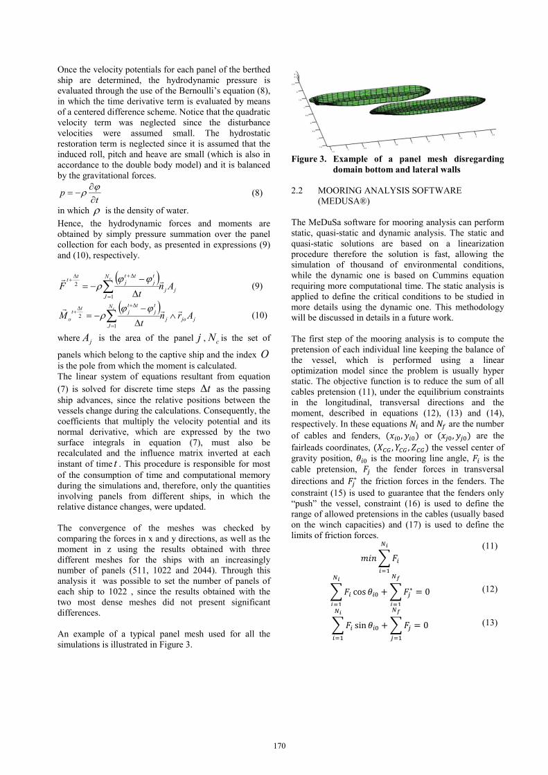
An example of a typical panel mesh used for all the
simulations is illustrated in Figure 3.
Figure 3. Example of a panel mesh disregarding
domain bottom and lateral walls
2.2 MOORING ANALYSIS SOFTWARE
(MEDUSA®)
The MeDuSa software for mooring analysis can perform
static, quasi-static and dynamic analysis. The static and
quasi-static solutions are based on a linearization
procedure therefore the solution is fast, allowing the
simulation of thousand of environmental conditions,
while the dynamic one is based on Cummins equation
requiring more computational time. The static analysis is
applied to define the critical conditions to be studied in
more details using the dynamic one. This methodology
will be discussed in details in a future work.
The first step of the mooring analysis is to compute the
pretension of each individual line keeping the balance of
the vessel, which is performed using a linear
optimization model since the problem is usually hyper
static. The objective function is to reduce the sum of all
cables pretension (11), under the equilibrium constraints
in the longitudinal, transversal directions and the
moment, described in equations (12), (13) and (14),
respectively. In these equations 𝑁𝑁𝑖𝑖 and 𝑁𝑁𝑒𝑒 are the number
of cables and fenders, (𝑥𝑥𝑖𝑖0, 𝑦𝑦𝑖𝑖0) or (𝑥𝑥𝑗𝑗0, 𝑦𝑦𝑗𝑗0) are the
fairleads coordinates, (𝑋𝑋𝐶𝐶𝐺𝐺 ,𝑌𝑌𝐶𝐶𝐺𝐺 ,𝑍𝑍𝐶𝐶𝐺𝐺) the vessel center of
gravity position, 𝜃𝜃𝑖𝑖0 is the mooring line angle, 𝐹𝐹𝑖𝑖 is the
cable pretension, 𝐹𝐹𝑗𝑗 the fender forces in transversal
directions and 𝐹𝐹𝑗𝑗∗ the friction forces in the fenders. The
constraint (15) is used to guarantee that the fenders only
“push” the vessel, constraint (16) is used to define the
range of allowed pretensions in the cables (usually based
on the winch capacities) and (17) is used to define the
limits of friction forces. 𝑚𝑚𝑖𝑖𝑐𝑐𝐹𝐹𝑖𝑖𝑁𝑁𝑐𝑐𝑖𝑖=1
(11)
𝐹𝐹𝑖𝑖 cos 𝜃𝜃𝑖𝑖0𝑁𝑁𝑐𝑐𝑖𝑖=1 +𝐹𝐹𝑗𝑗∗𝑁𝑁𝑓𝑓
𝑖𝑖=1 = 0
(12)
𝐹𝐹𝑖𝑖 sin𝜃𝜃𝑖𝑖0𝑁𝑁𝑐𝑐𝑖𝑖=1 +𝐹𝐹𝑗𝑗𝑁𝑁𝑓𝑓
𝑗𝑗=1 = 0
(13)
170
𝐹𝐹𝑖𝑖[sin𝜃𝜃𝑖𝑖0 (𝑥𝑥𝑖𝑖0 − 𝑋𝑋𝐶𝐶𝐶𝐶)− cos𝜃𝜃𝑖𝑖0(𝑦𝑦𝑖𝑖0 − 𝑌𝑌𝐶𝐶𝐶𝐶)
𝑁𝑁𝑖𝑖𝑖𝑖=1 −𝐹𝐹𝑗𝑗∗𝑁𝑁𝑓𝑓
𝑖𝑖=1 𝑦𝑦𝑗𝑗0 − 𝑌𝑌𝐶𝐶𝐶𝐶+ 𝐹𝐹𝑗𝑗𝑁𝑁𝑓𝑓
𝑖𝑖=1 𝑥𝑥𝑗𝑗0 − 𝑋𝑋𝐶𝐶𝐶𝐶 = 0
(14)
𝐹𝐹𝑗𝑗 > 0, 𝑗𝑗 = 1,2, …𝑁𝑁𝑓𝑓
(15) 𝐹𝐹𝑟𝑟𝑟𝑟𝑓𝑓𝑟𝑟𝑖𝑖𝑟𝑟 < 𝐹𝐹𝑖𝑖 < 𝐹𝐹𝑟𝑟𝑟𝑟𝑓𝑓𝑟𝑟𝑟𝑟𝑟𝑟, 𝑚𝑚 = 1,2, …𝑁𝑁𝑖𝑖
(16) −𝜇𝜇𝑟𝑟𝑟𝑟𝑟𝑟𝐹𝐹𝑗𝑗 ≤ 𝐹𝐹𝑗𝑗∗ ≤ 𝜇𝜇𝑟𝑟𝑟𝑟𝑟𝑟𝐹𝐹𝑗𝑗 , 𝑗𝑗 = 1,2, …𝑁𝑁𝑓𝑓 (17)
After the pretensions are computed the linear static
solution is computed based on Hooke’s law (18),
considering the linearized cable elongation (19), where
(Δ𝑥𝑥𝑖𝑖 ,Δ𝑦𝑦𝑖𝑖 ,Δ𝑧𝑧𝑖𝑖) are the fairlead motions, which can be
computed from the rigid body motions
(X1, X2, X3, X4, X5, X6)=(surge,sway,heave,roll,pitch,yaw)
using equation (20), assuming a linearization hypothesis.
𝐹𝐹𝑖𝑖 = 𝐾𝐾𝑖𝑖Δ𝑙𝑙𝑖𝑖 (18) Δ𝑙𝑙𝑖𝑖 =1𝑙𝑙0 (Δ𝑥𝑥𝑖𝑖0Δ𝑥𝑥𝑖𝑖 + Δ𝑦𝑦𝑖𝑖0Δ𝑦𝑦𝑖𝑖 + Δ𝑧𝑧𝑖𝑖0Δ𝑧𝑧𝑖𝑖),𝑚𝑚 = 1,2, …𝑁𝑁𝑖𝑖 +𝑁𝑁𝑓𝑓
(19)
Δ𝑥𝑥𝑖𝑖Δ𝑦𝑦𝑖𝑖Δ𝑧𝑧𝑖𝑖= X1X2
X3+ X5(zi0 − ZCG)− X6(yi0 − YCG)
X6(xi0 − XCG) − X4(zi0 − ZCG)
X4(ti0 − YCG)− X5(xi0 − XCG)
(20)
Therefore the additional cable forces (in relation to the
pretension) can be computed from the rigid body
motions, the 6 variables to be solved. The forces in each
cable or fender can be decomposed in forces and
moments in the 6 DoF. The sum of all cable forces
provides an equivalent stiffness matrix [𝐾𝐾𝑡𝑡]6𝑋𝑋6 and the
environmental forces acting in the vessel are defined by a
vector 𝐹𝐹6𝑋𝑋1. The linear system (21) is then solved to
compute body motions and after that the cables/fender
elongation. If the cable forces are negative or the fender
forces positive (considering the pretensions computed
previously) the cable/fender contribution to the stiffness
matrix is eliminated and the solution recomputed.
[𝐾𝐾𝑡𝑡]6𝑋𝑋6𝑋𝑋6𝑋𝑋1 = 𝐹𝐹6𝑋𝑋1
(21)
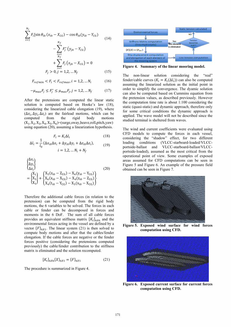
The procedure is summarized in Figure 4.
Figure 4. Summary of the linear mooring model.
The non-linear solution considering the “real”
fender/cable curves (𝐾𝐾𝑖𝑖 = 𝐾𝐾𝑖𝑖(Δ𝑙𝑙𝑖𝑖)) can also be computed
assuming the linearized solution as the initial point in
order to simplify the convergence. The dyamic solution
can also be computed based on Cummins equation from
the pretension values, as described previously. However
the computation time rate is about 1:100 considering the
static (quasi-static) and dynamic approach, therefore only
for some critical conditions the dynamic approach is
applied. The wave model will not be described since the
studied terminal is sheltered from waves.
The wind and current coefficients were evaluated using
CFD models to compute the forces in each vessel,
considering the “shadow” effect, for two different
loading conditions (VLCC-starboard-loaded/VLCC-
portside-ballast and VLCC-starboard-ballast/VLCC-
portside-loaded), assumed as the most critical from the
operational point of view. Some examples of exposed
areas assumed for CFD computations can be seen in
Figure 5 and Figure 6. An example of the pressure field
obtained can be seen in Figure 7.
Figure 5. Exposed wind surface for wind forces
computation using CFD.
Figure 6. Exposed current surface for current forces
computation using CFD.
Yes
This element
is eliminated
171
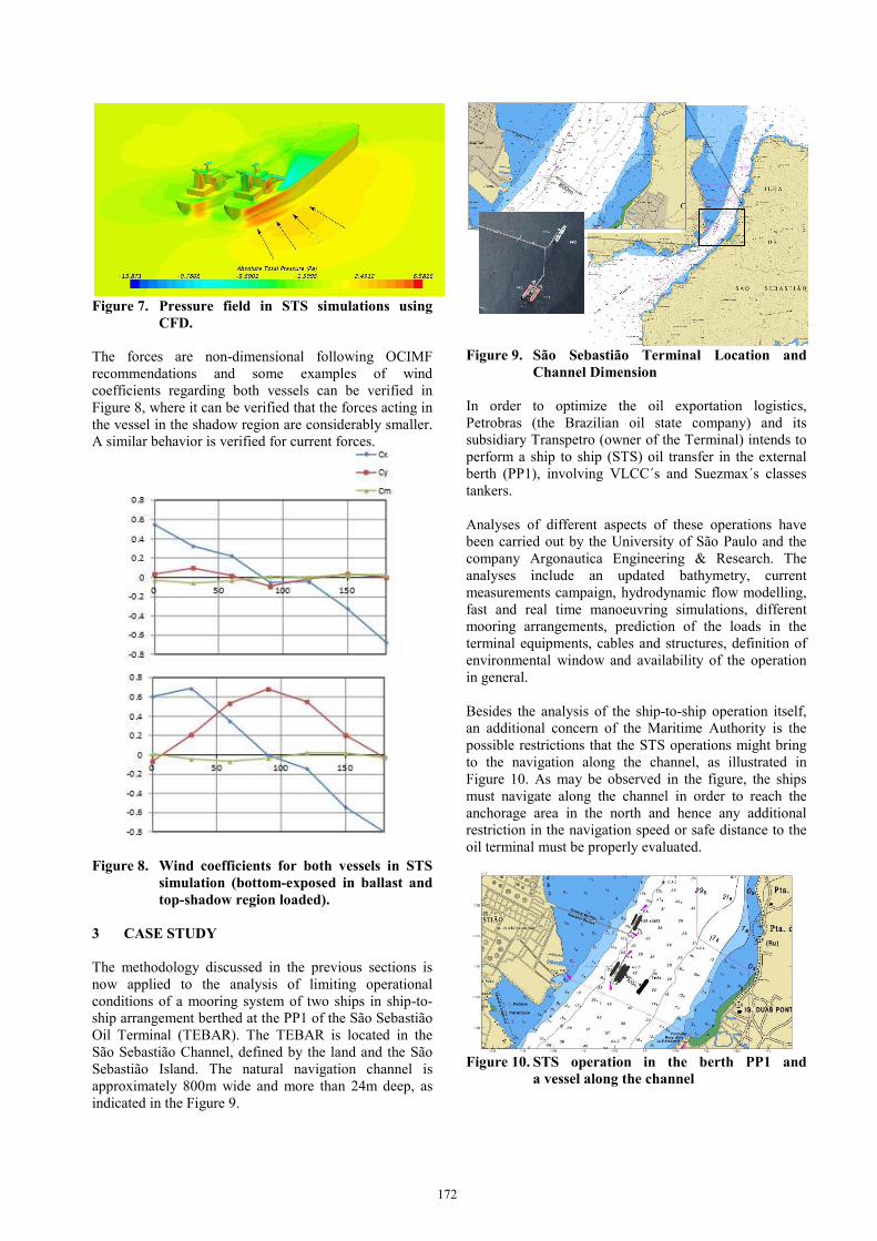
Figure 7. Pressure field in STS simulations using
CFD.
The forces are non-dimensional following OCIMF
recommendations and some examples of wind
coefficients regarding both vessels can be verified in
Figure 8, where it can be verified that the forces acting in
the vessel in the shadow region are considerably smaller.
A similar behavior is verified for current forces.
Figure 8. Wind coefficients for both vessels in STS
simulation (bottom-exposed in ballast and top-shadow region loaded).
3 CASE STUDY
The methodology discussed in the previous sections is
now applied to the analysis of limiting operational
conditions of a mooring system of two ships in ship-to-
ship arrangement berthed at the PP1 of the São Sebastião
Oil Terminal (TEBAR). The TEBAR is located in the
São Sebastião Channel, defined by the land and the São
Sebastião Island. The natural navigation channel is
approximately 800m wide and more than 24m deep, as
indicated in the Figure 9.
Figure 9. São Sebastião Terminal Location and
Channel Dimension
In order to optimize the oil exportation logistics,
Petrobras (the Brazilian oil state company) and its
subsidiary Transpetro (owner of the Terminal) intends to
perform a ship to ship (STS) oil transfer in the external
berth (PP1), involving VLCC´s and Suezmax´s classes
tankers.
Analyses of different aspects of these operations have
been carried out by the University of São Paulo and the
company Argonautica Engineering & Research. The
analyses include an updated bathymetry, current
measurements campaign, hydrodynamic flow modelling,
fast and real time manoeuvring simulations, different
mooring arrangements, prediction of the loads in the
terminal equipments, cables and structures, definition of
environmental window and availability of the operation
in general.
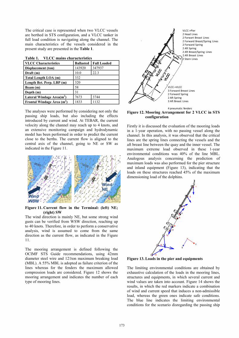
Besides the analysis of the ship-to-ship operation itself,
an additional concern of the Maritime Authority is the
possible restrictions that the STS operations might bring
to the navigation along the channel, as illustrated in
Figure 10. As may be observed in the figure, the ships
must navigate along the channel in order to reach the
anchorage area in the north and hence any additional
restriction in the navigation speed or safe distance to the
oil terminal must be properly evaluated.
Figure 10. STS operation in the berth PP1 and
a vessel along the channel
172
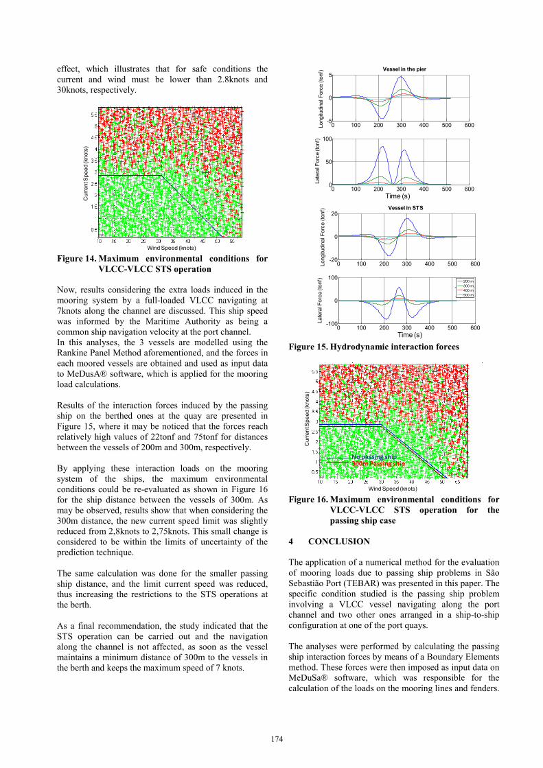
The critical case is represented when two VLCC vessels
are berthed in STS configuration, and a VLCC tanker in
full load condition is navigating along the channel. The
main characteristics of the vessels considered in the
present study are presented in the Table 1.
Table 1. VLCC mains characteristics VLCC Characteristics Ballasted Full Loaded Displacement (ton) 143920 347937
Draft (m) 10.0 22.3
Total Length LOA (m) 332
Length Bet. Perp. LBP (m) 320
Beam (m) 58
Depth (m) 31
Lateral Windage Area(m2) 7673 3744
Frontal Windage Área (m2) 1833 1132
The analyses were performed by considering not only the
passing ship loads, but also including the effects
introduced by current and wind. At TEBAR, the current
velocity along the channel may reach up to 4 knots, and
an extensive monitoring campaign and hydrodynamic
model has been performed in order to predict the current
close to the berths. The current flow is aligned to the
central axis of the channel, going to NE or SW as
indicated in the Figure 11.
Figure 11. Current flow in the Terminal: (left) NE; (right) SW
The wind direction is mainly NE, but some strong wind
gusts can be verified from WSW direction, reaching up
to 40 knots. Therefore, in order to perform a conservative
analysis, wind is assumed to come from the same
direction as the current flow, as indicated in the Figure
11.
The mooring arrangement is defined following the
OCIMF STS Guide recommendations, using 42mm
diameter steel wire and 121ton maximum breaking load
(MBL). A 55% MBL is adopted as failure criterion of the
lines whereas for the fenders the maximum allowed
compression loads are considered. Figure 12 shows the
mooring arrangement and indicates the number of each
type of mooring lines.
Figure 12. Mooring Arrangement for 2 VLCC in STS
configuration
Firstly it is discussed the evaluation of the mooring loads
in a 1-year operation, with no passing vessel along the
channel. In this analysis, it was observed that the critical
lines are the spring lines connecting the vessels and the
aft breast line between the quay and the inner vessel. The
maximum extreme load observed in these 1-year
environmental conditions was 40% of the line MBL.
Analogous analysis concerning the prediction of
maximum loads was also performed for the pier structure
and inland equipment (Figure 13), indicating that the
loads on these structures reached 45% of the maximum
dimensioning load of the dolphins.
Figure 13. Loads in the pier and equipments
The limiting environmental conditions are obtained by
exhaustive calculation of the loads in the mooring lines,
structures and equipments, in which several current and
wind values are taken into account. Figure 14 shows the
results, in which the red markers indicate a combination
of wind and current speed that induces a non-admissible
load, whereas the green ones indicate safe conditions.
The blue line indicates the limiting environmental
conditions for the scenario disregarding the passing ship
Wind WSW
Wind NE
VLCC->VLCC
3 Forward Breast Lines
2 Forward Spring
2 Aft Spring
3 Aft Breast Lines
4 pneumatic fenders
VLCC->Pier
2 Head Lines
2 Forwart Breast Lines
2 Forward Breast/Spring Lines
2 Forward Spring
2 Aft Spring
2 Aft Breast/Spring Lines
2 Aft Breast Lines
2 Stern Lines
173
effect, which illustrates that for safe conditions the
current and wind must be lower than 2.8knots and
30knots, respectively.
Figure 14. Maximum environmental conditions for
VLCC-VLCC STS operation
Now, results considering the extra loads induced in the
mooring system by a full-loaded VLCC navigating at
7knots along the channel are discussed. This ship speed
was informed by the Maritime Authority as being a
common ship navigation velocity at the port channel.
In this analyses, the 3 vessels are modelled using the
Rankine Panel Method aforementioned, and the forces in
each moored vessels are obtained and used as input data
to MeDusA® software, which is applied for the mooring
load calculations.
Results of the interaction forces induced by the passing
ship on the berthed ones at the quay are presented in
Figure 15, where it may be noticed that the forces reach
relatively high values of 22tonf and 75tonf for distances
between the vessels of 200m and 300m, respectively.
By applying these interaction loads on the mooring
system of the ships, the maximum environmental
conditions could be re-evaluated as shown in Figure 16
for the ship distance between the vessels of 300m. As
may be observed, results show that when considering the
300m distance, the new current speed limit was slightly
reduced from 2,8knots to 2,75knots. This small change is
considered to be within the limits of uncertainty of the
prediction technique.
The same calculation was done for the smaller passing
ship distance, and the limit current speed was reduced,
thus increasing the restrictions to the STS operations at
the berth.
As a final recommendation, the study indicated that the
STS operation can be carried out and the navigation
along the channel is not affected, as soon as the vessel
maintains a minimum distance of 300m to the vessels in
the berth and keeps the maximum speed of 7 knots.
Figure 15. Hydrodynamic interaction forces
Figure 16. Maximum environmental conditions for
VLCC-VLCC STS operation for the passing ship case
4 CONCLUSION
The application of a numerical method for the evaluation
of mooring loads due to passing ship problems in São
Sebastião Port (TEBAR) was presented in this paper. The
specific condition studied is the passing ship problem
involving a VLCC vessel navigating along the port
channel and two other ones arranged in a ship-to-ship
configuration at one of the port quays.
The analyses were performed by calculating the passing
ship interaction forces by means of a Boundary Elements
method. These forces were then imposed as input data on
MeDuSa® software, which was responsible for the
calculation of the loads on the mooring lines and fenders.
Wind Speed (knots)
Cu
rre
ntS
pe
ed
(kn
ots
)
Time (s)
0 100 200 300 400 500 600-5
0
5
Fx N
avio
píe
r (t
onf)
0 100 200 300 400 500 6000
50
100
Fy N
avio
píe
r (t
onf)
Longitu
din
al F
orc
e (
tonf)
Vessel in the pier
Late
ral F
orc
e (to
nf)
0 100 200 300 400 500 600-20
0
20
Fx N
avio
ST
S (
tonf)
0 100 200 300 400 500 600-100
0
100
Fy N
avio
ST
S (
tonf)
Vessel in STS
Longitu
din
al F
orc
e (
tonf)
Late
ral F
orc
e (to
nf)
Time (s)
200 m
300 m
400 m
500 m
Wind Speed (knots)
Cu
rre
ntS
pe
ed
(kn
ots
)
No passing ship300m Passing ship
174
Besides, current and wind loads were also taken into
account.
The results were focused on the definition of limiting
environmental conditions to the ship-to-ship operations
at the port quay, which were determined for scenarios
with and without the influence of the VLCC navigating
along the channel.
Results have shown that the VLCC navigating at the port
channel at 7 knots in a distance shorter than 300 m was
responsible for the imposition of a restrictive condition
of current speed for the STS operations. Moreover, the
results have also illustrated that as soon as the navigating
vessel maintains a minimum distance of 300m to the
vessels in the berth and keeps the maximum speed up to
7 knots the STS operations are not significant affected.
5 ACKNOWLEDGEMENTS Authors gratefully acknowledge Petrobras for allowing
the publication of the results. Third author acknowledge
the CNPq by the research grant (process 308645/2013-8).
6 REFERENCES 1. Remery, G.F.M. (1974). Mooring Forces Induced
by Passing Ships, Offshore Technology Conference.
2. Delefortrie, G. ; Vantorre, M. ; Cappelle, J. ; Ides,
S. (2012). The Effect of Shipping Traffic on Moored
Ships. 10th International Conference on Hydrodynamics,
October 1 - 4, St. Petersburg, Russia.
3. Duffy, J.T. ; Denehy, S. ; Ranmuthugala, D ;
Renilson, M.R. (2013). The effect of berth blockage on
berthed ship - passing ship interaction. Conference
Proceedings, 3rd International Conference on Ship
Manoeuvring in Shallow and Confined Water, 3-5 June,
Ghent, Belgium, pp. 237-247.
4. Kriebel, D. ; Seelig, W. ; Eskijian, M. (2005).
Mooring loads due to parallel passing ships. Naval
Facilities Engineering Service Center, Port Hueneme,
California, USA.
5. Flory, J. (2002). The Effect of Passing Ships on
Moored Ships, Prevention First 2002 Symposium,
California State Lands Commission, USA.
6. Varyani, K.S. ; Vantorre, M. (2006). New Generic
Equations for Interaction Effects on a Moored
Containership Due to a Passing Tanker. Journal of Ship
Research, Vol. 50, No. 3.
7. Wang, S. (1975). Dynamic effects of ships passage
on moored vessel, Journal of Waterways, Harbours and
Coastal Engineering Division.
8. Yang, H. ; Wu, B.S. ; Miao, Q.M. ; Xiang, X. ;
Berg, T.E. ; Kuang, X.F. (2011). Study on the Effects of
Unsteady Ship to Ship Interaction by CFD Method. 2nd
International Conference on Ship Manoeuvring and
Confined Water: Ship to Ship Interaction.
9. Xiang, X. ; O.M. Faltinsen. (2010). Manoeuvring of
two interacting ships in calm water, PRADS, Rio de
Janeiro, Brazil
10. Bunnik, T. ; Toxopeus, S. (2011). Viscous Flow
Effects of Passing Ships in Ports. Proceedings of the
ASME 2011 30th International Conference on Ocean,
Offshore and Arctic Engineering OMAE2011, Roterdam,
The Netherlands.
11. Watai, R.A. ; Ruggeri, F. ; Tannuri, E. A. ; Weiss, J.
(2013). Evaluation of empirical and numerical methods
on the prediction of hydrodynamic loads involved in the
passing ship problem, 3rd International Conference on
Ship Manoeuvring in Shallow and Confined Water, 3-5
June, Ghent, Belgium, p. 167-175.
12. Araujo, M.F.B.P. ; Pereira, A.A.P. ; Carmignotto,
M.A.P. ; Weiss, J.G.M. ; Gandara, M.A. (2011). Mooring
Loads Induced by other Ships in Navigation Channels.
XXII COPINAVAL – IPIN, Buenos Aires, Argentina.
13. Korshmeyer, F.T. ; Newman, J.N. (1993).
Computational of Ship Interaction Forces in Restricted
Waters, Journal of Ship Research.
14. Pinkster, J.A. (2004). The Influence of a Free
Surface on Passing Ship Effects, Int. Shipbuilding Prog.,
51, no. 4.
15. Hess, J.L. ; Smith, A.M.O. (1964). Calculation of
nonlifting potential flow about arbitrary three-
dimensional bodies, Journal of Ship Research.
16. Varyani, K.S. ; Krishnankutty, P. (2006).
Modification of ship hydrodynamic interaction forces
and moment by underwater ship geometry. Ocean
Engineering, Vol. 33, pp. 1090-1104.
7 AUTHORS’ BIOGRAPHIES
Felipe Ruggeri, M.Sc, Mr. Ruggeri has graduation and
M.Sc degrees from the Naval Architect and Ocean
Engineering Department of the University of São Paulo
(USP) in 2010 and 2012, respectively, and is a Ph.D
candidate developing the thesis entitled as “A Numerical
Method for Non Linear Analysis of the Dynamics of
Marine Systems under Gravity Waves and Current”.
From 2008 to 2015, he worked as a research engineer at
the Tanque de Provas Numérico of USP developing
projects on green ship designs, high speed vessels for
crew transportation and also design of logistic hubs for
the Pre-Salt layer in Brazil. Mr. Ruggeri is one of the
founders and director of ARGONAUTICA
175
ENGINEERING AND RESEARCHES where he has
been mainly involved in the conduction of fast-time
simulations for maneuvering analysis and development
of innovative numerical tools to improve operational
safety and efficiency of ports, which includes, for
example, the development of ReDRAFT® (Real Time
Draft) and MeDuSa® (Mooring Design Tool) software.
Rafael de Andrade Watai, Ph.D, Dr. Watai is
graduated (2010) and Doctor of Sciences (2014) in Naval
Architect and Ocean Engineering by the University of
São Paulo (USP). From 2006 to 2014 he worked as a
researcher at the Tanque de Provas Numérico of USP,
participating on research projects of marine structures for
oil exploration, mainly involved in mooring system
designs, development of hydrodynamic numerical tools
and model tests conduction and specification. Dr. Watai
is one of the founders and director of ARGONAUTICA
ENGINEERING AND RESEARCHES where he has
been actively involved in the implementation of
computational hydrodynamic tools for seakeeping
analysis of floating bodies, hydrodynamic interaction
problems induced by the passing ships effect and also for
breakwater efficiency predictions.
Eduardo Aoun Tannuri, Associate Professor at the
Department of Mechatronics Engineering, Escola
Politécnica, University of São Paulo (EPUSP), and one
of the coordinators of the Numerical Offshore Tank
(TPN). Member of ITTC Maneuvering Committee.
Works on Dynamic Positioning (DP) Systems applied to
offshore vessels and platforms, Maneuvering and Sea-
keeping time-domain simulation codes development and
application and Experimental analysis of floating
structures. He coordinates several R&D projects in the
area of offshore oils&gas exploration, maritime and river
navigation and port development.
176


![Kerrie Mengersen Fabrizio Ruggeri arXiv:1703.02151v3 [stat.CO] … · 2019. 10. 21. · Anthony Ebert, Paul Wu, Kerrie Mengersen, Fabrizio Ruggeri 3 then customers must wait in the](https://img.pdfslide.us/doc/110x75/60df293485441e5e500f3cb0/kerrie-mengersen-fabrizio-ruggeri-arxiv170302151v3-statco-2019-10-21-anthony.jpg)