Embed Size (px)
Citation preview
RuggedSwitch™ RS8000 / RS1600 / RS900
Product Family User Guide
RS1600TRS1600T
RS1600RS1600
RS8000RS8000 RS8000TRS8000T
RuggedCom Inc.64 Jardin Dr. (Unit 3G) Concord, Ontario Canada L4K 3P3 Web: www.ruggedcom.comTel: (905) 760-7799 Fax: (905) 760-9909 Toll Free: (888) 264 – 0006
RuggedSwitch™ User Guide
RUGGEDSWITCH™ USER GUIDE FOR USE WITH RS8000, RS1600, AND RS900 PRODUCTS
RUGGEDSWITCH™ OPERATING SYSTEM V1.5
Version 1.5.1 – Aug. 3, 2004
RuggedCom 64 Jardin Drive, Unit 3G
Concord, Ontario
Canada L4K 3P3
Voice: (905) 760-7799
1-(888) 264-0006
Fax: (905) 760-9909 [email protected] http://www.RuggedCom.com
Disclaimer
RuggedCom Inc. makes no warranty of any kind with regard to this material.
RuggedCom shall not be liable for errors contained herein or for consequential damages in connection with the furnishing, performance, or use of this material.
Warranty Five (5) years from date of purchase, return to factory. For warranty details, visit www.ruggedcom.com or contact your customer service representative. COPYRIGHT © Dec 2002 RuggedCom Inc.
ALL RIGHTS RESERVED
This document contains proprietary information, which is protected by copyright. All rights are reserved.
No part of this document may be photocopied, reproduced or translated to another language without the prior written consent of RuggedCom Inc.
2 RuggedCom
About this User Guide
ABOUT THIS USER GUIDE This guide is concerned with aiding the user in the configuration and operation of the RuggedSwitch™ using the RuggedCom User Interface. Specifically, this guide details aspects of: • Accessing the User Interface
• Security (passwords)
• Configuring the switch
• Status determination
• Performance measurement
• Uploading and downloading files
• Dealing with alarms This guide is intended solely for the purpose of familiarizing the reader with the ways that the RuggedSwitch™ can be used to support Ethernet switching applications.
Applicable Firmware Revision This guide is applicable to RuggedSwitch™ Operating System (ROS) software revision 1.5.x.
Who Should Use This User Guide This guide is to be used by network technical support personnel who are familiar with the operation of networks. Others who might find the book useful are network and system planners, system programmers and line technicians.
How To Use This User Guide
The index of this guide has been prepared with: • Entries to each of the “Features” sections of the manual,
• Entries to each of the “Troubleshooting” sections of the manual (located at the end of each chapter),
• Entries to each of the Menus, organized by name.
It is recommended that you use this guide along with the following applicable documents.
RuggedSwitch™ RS8000 Family Installation Guide
RuggedSwitch™ RS1600 Family Installation Guide
RuggedSwitch™ RS900 Family Installation Guide
RuggedCom 1
RuggedSwitch™ User Guide
Rugged MediaConverter™ Installation Guide RuggedCom Fiber Guide White paper: Rapid Spanning Tree in Industrial Networks
Document Conventions This publication uses the following conventions:
Note: Means reader take note. Notes contain helpful suggestions or references to materials not contained in this guide.
Quick Start Recommendations The following description is included to aid those users experienced with switches that may wish to attempt to configure the switch without fully reading the guide. Commands strings have been provided with their full path from the root menu. 1. Locate/mount the chassis in its final resting place. 2. Attach a PC running terminal emulation software to the RS232 port and apply
power to the chassis (default baud rate, data bits, parity - “57600 8 n”, no hardware/software flow control). Set the terminal type to VT100. Gain access to the UI (Type <CR>, the default password string is set to “admin”, see Chapter 1).
3. Configure the switch’s IP address (Administration, Configure IP Services, IP Address) and Subnet Mask (Administration, Configure IP Services, Subnet). If instead you wish the switch to load the address via DHCP, set the address type to dynamic (Administration, Configure IP Services, IP Address Type). See Chapter 1 for more details.
4. You may wish to change the default guest, operator and administration passwords (Administration, Configure IP Services, Configure Passwords). See Chapter 1 for more details.
5. The ports are already set up with sensible defaults and autoselects where possible. You may want to hard configure specific settings such as speed, duplex, flow control and far end fault detection. Broadcast filtering is activated. See Chapter 3 for more details.
6. RSTP is enabled for the bridge by default and can be disabled if desired (Spanning Tree, Configure Bridge RSTP Parameters, State). RSTP may also be forced to support only legacy STP (Spanning Tree, Configure Bridge RSTP Parameters, Version Support). Note that the switch deals with legacy STP pathcosts by default and can be set to deal with larger path costs (Spanning Tree, Configure Bridge RSTP Parameters, Cost Style). RSTP may also be set enabled/disabled on a per port basis (Spanning Tree, Configure Port RSTP Parameters, Enable). You may also want to identify controllers and IEDs by setting the Edge parameter to True for those ports (Spanning Tree, Configure Port RSTP Parameters, Edge). See Chapter 6 for more details.
2 RuggedCom
About this User Guide
7. At this point the switch will raise links, learn addresses and forward traffic. By default link alarms and SNMP linkUp/linkDown traps (See Chapter 1) are raised for all ports. The Port Configuration and Status, View Port Status command will indicate the current state of the ports in real time. The Ethernet Statistics, View Ethernet Statistics command will provide a useful indication of traffic on the switch. The Spanning Tree, View Port RSTP Statistics command will provide an indication of which ports have been blocked to prevent traffic loops.
8. By default the switch has VLAN 1 configured on all ports (VLAN 1 is always present for management purposes). IGMP is disabled for VLAN 1 by default and can be enabled by the Virtual LANs, Configure Static VLANs, IGMP command.
9. If remote SNMP management or traps are desired, configure the appropriate manage station (Administration, Configure SNMP Management Stations).
10. Ports that are not in use should be disabled (Port Configuration and Status, Configure Port Parameters Command) to improve security, increase performance, reduce power consumption and cause the switch to run cooler.
11. Further concerns such as configuring static MAC addresses, port security, VLANs and IGMP as well as ensuring robustness, measuring and optimizing performance are dealt with by reading the guide fully.
For Users Migrating From Revisions ROS 1.2 and Earlier.. 1. The “operator” access level has been created. The ability to configure, view and
operate product features has been aligned with the guest, operator and administration access levels. All passwords are now stored in the configuration file in an encrypted form.
2. The TFTP Server feature is now configurable. It may be configured to be disabled, to only allow files to be retrieved or to provide full access.
3. The CLI shell provides a TFTP client command that can be used to upload and download files from TFTP servers.
4. Port Mirroring has been moved from the Diagnostics menu to the Port Configuration and Status menu.
5. The system log may now be viewed and cleared from the Diagnostics menu.
RuggedCom 3
RuggedSwitch™ User Guide
Table Of ContentsAbout this User Guide............................................................................................................................ i
Applicable Firmware Revision .............................................................................................................. i Who Should Use This User Guide......................................................................................................... i How To Use This User Guide................................................................................................................ i Document Conventions......................................................................................................................... ii Quick Start Recommendations.............................................................................................................. ii For Users Migrating From Revisions ROS 1.2 and Earlier.. ............................................................... iii
Table Of Contents ................................................................................................................................ iv
Chapter 1– Setting Up And Administering The Switch ........................................................................1 Introduction............................................................................................................................................1 The RuggedSwitch™ User Interface......................................................................................................1
Using the RS232 Port to Access the User Interface ..............................................................................1 The Structure of the User Interface........................................................................................................3 Making Configuration Changes .............................................................................................................4 Updates Occur In Real Time..................................................................................................................4 Alarm Indications Are Provided ............................................................................................................4 The CLI Shell.........................................................................................................................................4
Administration Menu .............................................................................................................................5 Configure IP Services ............................................................................................................................5
IP Address Type.....................................................................................................................................5 IP Address ..............................................................................................................................................6 Subnet ....................................................................................................................................................6 Gateway .................................................................................................................................................6 Inactivity Timeout..................................................................................................................................6 Telnet Sessions.......................................................................................................................................6 TFTP Server...........................................................................................................................................7 SNMP Get Community..........................................................................................................................7
Configuring System Identification.........................................................................................................8 Configure Passwords..............................................................................................................................8 Configure Time and Date.......................................................................................................................8
Time .......................................................................................................................................................9 Date ........................................................................................................................................................9 Time Zone ..............................................................................................................................................9 NTP Server Address...............................................................................................................................9 NTP Update Period ................................................................................................................................9
Configure SNMP Management Stations..............................................................................................10 Community String................................................................................................................................10 Address.................................................................................................................................................10 Set Access ............................................................................................................................................10 Send Traps............................................................................................................................................11
Troubleshooting ...................................................................................................................................12
Chapter 2 - Configuring MAC Address Management .........................................................................13 Introduction..........................................................................................................................................13
MAC Address Management Features ..................................................................................................13 MAC Address Management Configuration .........................................................................................13
RuggedCom
Table Of Contents
MAC Address Management Parameter Ranges & Default Settings....................................................13 MAC Address Tables Management Menu...........................................................................................13 Viewing MAC Addresses ....................................................................................................................14 Purge MAC Address Table ..................................................................................................................15 Configure MAC Address Learning Options .......................................................................................15 Configure Static MAC Address Table .................................................................................................15
Chapter 3 – Configuring the Ports .......................................................................................................18 Introduction..........................................................................................................................................18
Port Features ........................................................................................................................................18 Port Applications..................................................................................................................................19
Port Security ........................................................................................................................................19 Broadcast Rate Limiting ......................................................................................................................20 Controller Protection Through Loss-of-Link Management .................................................................21
Using Port Mirroring............................................................................................................................22 Introduction..........................................................................................................................................22 Configuring Port Mirroring..................................................................................................................22
Port Configuration And Status.............................................................................................................23 Port Parameter Ranges & Default Settings ..........................................................................................23 Port Configuration Menu .....................................................................................................................24 Port Rate Limiting Menu .....................................................................................................................25 Port Security Menu ..............................................................................................................................26 Port Mirroring Menu............................................................................................................................28 Viewing Port Status .............................................................................................................................29 Resetting Ports .....................................................................................................................................29
Troubleshooting ...................................................................................................................................30
Chapter 4 – Configuring VLANs.........................................................................................................31 Introduction..........................................................................................................................................31
VLAN Features ....................................................................................................................................31 VLAN Concepts And Issues ................................................................................................................32
VLANs and Tags .................................................................................................................................32 Tagged vs. Untagged Frames...............................................................................................................32 Native VLAN.......................................................................................................................................32 Management VLAN.............................................................................................................................33 Edge And Trunk Port Types ................................................................................................................34 Forbidden Port Lists.............................................................................................................................34 VLAN Based Services ........................................................................................................................34
VLAN Applications .............................................................................................................................34 Traffic Domain Isolation......................................................................................................................34 Administrative Convenience................................................................................................................35 Reduced Hardware...............................................................................................................................35 Service Differentiation.........................................................................................................................36
VLAN Configuration ...........................................................................................................................36 VLAN Parameter Ranges & Default Settings......................................................................................36 Virtual LANs Menu .............................................................................................................................37 Static VLANs Menu.............................................................................................................................37 Port VLAN Parameters Menu..............................................................................................................39 VLAN Summary Menu .......................................................................................................................42
Troubleshooting ...................................................................................................................................43
RuggedCom 5
RuggedSwitch™ User Guide
Chapter 5 – Configuring Class of Service ...........................................................................................44 Introduction to CoS..............................................................................................................................44
CoS Features ........................................................................................................................................44 CoS Concepts And Issues ....................................................................................................................44
CoS Operation......................................................................................................................................44 CoS Configuration ...............................................................................................................................46
CoS Parameter Ranges & Default Settings..........................................................................................46 Classes Of Service Menu .....................................................................................................................46 Global CoS Parameters Menu..............................................................................................................47 Port CoS Parameters Menu..................................................................................................................47 Priority to CoS Mapping Menu............................................................................................................48 DSCP to CoS Mapping Menu..............................................................................................................48 CoS Access Priorities Menu ................................................................................................................49
Chapter 6 – Configuring Rapid Spanning Tree ...................................................................................50 Introduction .........................................................................................................................................50
RSTP Features......................................................................................................................................50 RSTP Concepts And Issues .................................................................................................................51
RSTP Operation ...................................................................................................................................51 RSTP Applications...............................................................................................................................58 RSTP Configuration.............................................................................................................................61
Bridge and Port Parameter Ranges & Default Settings .......................................................................61 Spanning Tree Menu............................................................................................................................62 Bridge RSTP Parameters Menu ...........................................................................................................62 Port RSTP Parameters Menu ...............................................................................................................64
RSTP Statistics ....................................................................................................................................66 Bridge RSTP Statistics Menu ..............................................................................................................66 Port RSTP Statistics Menu...................................................................................................................68
Troubleshooting ...................................................................................................................................71
Chapter 7 – Configuring Multicast Filtering........................................................................................75 Introduction to Multicast Filtering.......................................................................................................75
IGMP Features .....................................................................................................................................75 IGMP Concepts And Issues .................................................................................................................77
Router IGMP Operation.......................................................................................................................77 Switch IGMP Active and Passive Operation .......................................................................................78 Combined Router And Switch IGMP Operation .................................................................................79
Multicast Filtering Configuration ........................................................................................................82 Multicast Filtering Parameter Ranges & Default Settings...................................................................82 Multicast Filtering Menu .....................................................................................................................82 IGMP Parameters Menu......................................................................................................................82
Multicast Filtering Statistics ................................................................................................................83 IP Multicast Groups Menu...................................................................................................................83
Troubleshooting ...................................................................................................................................86
Chapter 8 – Diagnostics .......................................................................................................................89 Introduction..........................................................................................................................................89 Using The Alarm System.....................................................................................................................89
Alarm Concepts And Issues.................................................................................................................89 Viewing And Clearing Alarms ............................................................................................................91
Viewing Alarms ...................................................................................................................................91
RuggedCom
Table Of Contents
Clearing Alarms ...................................................................................................................................92 Viewing CPU Diagnostics ...................................................................................................................93 Viewing and Clearing the System Log ................................................................................................95 Viewing Product Identification............................................................................................................95 Load Factory Default Configuration....................................................................................................96 Resetting The Unit ...............................................................................................................................96
Chapter 9 – Using Ethernet And RMON Statistics..............................................................................97 Introduction..........................................................................................................................................97 View Ethernet Statistics .......................................................................................................................98 View Ethernet Port Statistics ...............................................................................................................98 Remote Monitoring (RMON) ............................................................................................................100 RMON Historical Statistics Concepts And Issues.............................................................................101
Configure RMON History Control Table Menu................................................................................102 RMON History Samples Table Menu................................................................................................103
RMON Alarms And Events Concepts And Issues.............................................................................104 The Alarm Process .............................................................................................................................104 Alarm Generation And Hysteresis .....................................................................................................105 Delta vs. Absolute Values..................................................................................................................105 Configure RMON Alarms..................................................................................................................106 Configure RMON Events...................................................................................................................108 RMON Event Logs ............................................................................................................................109 Troubleshooting .................................................................................................................................111
Chapter 10 - Using The CLI Shell .....................................................................................................112 Introduction........................................................................................................................................112 Entering And Leaving The Shell .......................................................................................................112 Summary Of Commands....................................................................................................................113 Viewing Files .....................................................................................................................................114
Dir command......................................................................................................................................114 Viewing And Clearing Log Files ......................................................................................................114
Running Loopback Tests ...................................................................................................................115 Pinging A Remote Device..................................................................................................................116 Tracing Events ...................................................................................................................................117
Enabling Tracing................................................................................................................................117 Starting The Trace..............................................................................................................................118
Viewing DHCP Learned Information Using Ipconfig.......................................................................119 Executing Commands Remotely Through RSH ................................................................................120 Resetting The Switch .........................................................................................................................120
Chapter 11 – Upgrading Firmware And Managing Configurations ..................................................121 Introduction........................................................................................................................................121 Upgrading Firmware ..........................................................................................................................121
Upgrading Firmware With Xmodem .................................................................................................122 Upgrading Firmware Using A TFTP Client On Your Workstation...................................................122 Upgrading Firmware Using The TFTP Client On Your RuggedSwitch™ ........................................124
Capturing Configurations...................................................................................................................125 Capturing Configurations With XModem .........................................................................................125 Capturing Configurations With TFTP ...............................................................................................125
Using SQL Commands ......................................................................................................................127 Getting Started ...................................................................................................................................127
RuggedCom 7
RuggedSwitch™ User Guide
Finding The Correct Table.................................................................................................................128 Retrieving Information.......................................................................................................................128 Changing Values In A Table..............................................................................................................129 Defaulting A Table.............................................................................................................................130 Using RSH And SQL.........................................................................................................................130
Appendix A - Menu Tree ...................................................................................................................131
Appendix B - SNMP MIB Support....................................................................................................132
Appendix C – SNMP Trap Summary ................................................................................................132
Appendix D – RMON Acceptable MIB Parameters..........................................................................133
Index...................................................................................................................................................137
RuggedCom
Table Of Figures
TABLE OF FIGURES
Figure 1: Main Menu With Screen Elements Identified ........................................................................3
Figure 2: Administration Menu .............................................................................................................5
Figure 3: IP Services Configuration Menu ............................................................................................5
Figure 4: Time and Date Menu..............................................................................................................8
Figure 5: SNMP Management Stations Menu .....................................................................................10
Figure 6: Using A Router As A Gateway ............................................................................................12
Figure 7: MAC Address Tables Menu.................................................................................................13
Figure 8: MAC Addresses Menu .........................................................................................................14
Figure 9: MAC Addresses Learning Options Menu ............................................................................15
Figure 10: Static MAC Address Table Menu ......................................................................................16
Figure 11: Controller Protection Through FEFI ..................................................................................21
Figure 12: Port Configuration And Status Menu.................................................................................23
Figure 13: Port Parameters Menu ........................................................................................................24
Figure 14: Port Rate Limiting Menu....................................................................................................26
Figure 15: Port Security Menu.............................................................................................................26
Figure 16: Port Mirroring Menu ..........................................................................................................28
Figure 17: Port Status Menu ................................................................................................................29
Figure 18: Multiple and Overlapping VLANs.....................................................................................35
Figure 19: Inter-VLAN Communications............................................................................................36
Figure 20: Virtual LANs Menu............................................................................................................37
Figure 21: Static VLANs Menu...........................................................................................................37
Figure 22: Port VLAN Parameters Menu ............................................................................................39
Figure 23: VLAN Summary Menu ......................................................................................................42
Figure 24: Determining The CoS Of A Received Frame ....................................................................45
Figure 25: Use of CoS When Forwarding Frames ..............................................................................46
Figure 26: Classes Of Service Menu....................................................................................................46
RuggedCom 9
RuggedSwitch™ User Guide
Figure 27: Global CoS Parameters Menu ............................................................................................47
Figure 28: Port CoS Parameters Menu ................................................................................................47
Figure 29: Priority to CoS Mapping Menu ..........................................................................................48
Figure 30: TOS DSCP to CoS Mapping ..............................................................................................48
Figure 31: CoS Access Priorities Menu...............................................................................................49
Figure 32: Bridge and Port States ........................................................................................................52
Figure 33: Bridge and Port Roles.........................................................................................................54
Figure 34: Example Of A Structured Wiring Configuration ...............................................................58
Figure 35: Example Of A Ring Backbone Configuration....................................................................59
Figure 36: Port Redundancy ................................................................................................................60
Figure 37: Spanning Tree Menu ..........................................................................................................62
Figure 38: Bridge RSTP Parameters Menu..........................................................................................62
Figure 39: Port RSTP Parameters Menu..............................................................................................64
Figure 40: Bridge RSTP Status Menu .................................................................................................66
Figure 41: Port RSTP Parameters Menu..............................................................................................68
Figure 42: IGMP Operation Example 1...............................................................................................77
Figure 43: IGMP Operation Example 2...............................................................................................79
Figure 44: Multicast Filtering Menu....................................................................................................82
Figure 45: IGMP Parameters Menu.....................................................................................................82
Figure 46: IP Multicast Groups Menu .................................................................................................83
Figure 47: Diagnostics Menu Showing Alarm Commands .................................................................89
Figure 48: Alarms Menu......................................................................................................................91
Figure 49: CPU Diagnostics Menu ......................................................................................................93
Figure 50: Viewing the System Log ....................................................................................................95
Figure 51: Ethernet Statistics Menu.....................................................................................................97
Figure 52: Ethernet Statistics Menu.....................................................................................................98
Figure 53: Port Statistics Menu............................................................................................................98
RuggedCom
Table Of Figures
Figure 54: The History Process..........................................................................................................101
Figure 55: History Control Table.......................................................................................................102
Figure 56: RMON History Samples Table ........................................................................................103
Figure 57: The Alarm Process ...........................................................................................................104
Figure 58: Applying Hysteresis to Alarm Generation .......................................................................105
Figure 59: RMON Alarm Configuration Table screens.....................................................................106
Figure 60: RMON Events Configuration Table screens....................................................................108
Figure 61: RMON Events Configuration Table screens....................................................................109
Figure 62: Running a Loopback Test ................................................................................................115
Figure 63: Displaying Trace settings ................................................................................................117
Figure 64: Changing Trace settings ...................................................................................................118
Figure 65: Starting A Trace ...............................................................................................................118
Figure 66 Example of an Upgrade using XModem ...........................................................................122
Figure 67 Example of an Upgrade using a TFTP client on your workstation ...................................124
Figure 68 Example of an Upgrade using the TFTP client on the RuggedSwitch™...........................125
Figure 69 The sql command and SQL help .......................................................................................127
Figure 70 The sql command and SQL help .......................................................................................128
Figure 71 Selecting a table.................................................................................................................128
Figure 72 Select a parameter with a table ..........................................................................................129
Figure 73 Selecting rows in a table based upon parameter values.....................................................129
Figure 74 Selecting rows in a table based upon multiple parameter values ......................................129
Figure 75 Changing Values In A Table .............................................................................................129
Figure 76 Defaulting A Table ............................................................................................................130
Figure 77 Bulk Inspections Using RSH and SQL .............................................................................130
RuggedCom 11

Chapter 1– Setting Up And Administering The Switch
Chapter 1– Setting Up And Administering The Switch
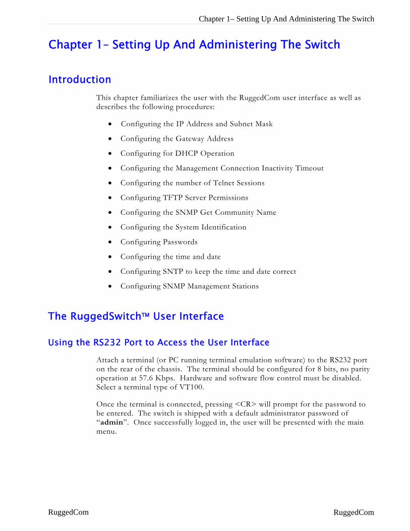
Introduction This chapter familiarizes the user with the RuggedCom user interface as well as describes the following procedures:
• Configuring the IP Address and Subnet Mask
• Configuring the Gateway Address
• Configuring for DHCP Operation
• Configuring the Management Connection Inactivity Timeout
• Configuring the number of Telnet Sessions
• Configuring TFTP Server Permissions
• Configuring the SNMP Get Community Name
• Configuring the System Identification
• Configuring Passwords
• Configuring the time and date
• Configuring SNTP to keep the time and date correct
• Configuring SNMP Management Stations
The RuggedSwitch™ User Interface
Using the RS232 Port to Access the User Interface
Attach a terminal (or PC running terminal emulation software) to the RS232 port on the rear of the chassis. The terminal should be configured for 8 bits, no parity operation at 57.6 Kbps. Hardware and software flow control must be disabled. Select a terminal type of VT100.
Once the terminal is connected, pressing <CR> will prompt for the password to be entered. The switch is shipped with a default administrator password of “admin”. Once successfully logged in, the user will be presented with the main menu.
RuggedCom RuggedCom
RuggedSwitch™ User Guide
The Structure of the User Interface
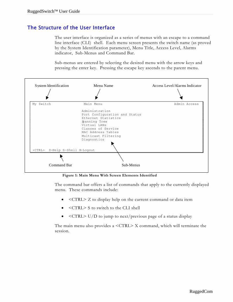
The user interface is organized as a series of menus with an escape to a command line interface (CLI) shell. Each menu screen presents the switch name (as proved by the System Identification parameter), Menu Title, Access Level, Alarms indicator, Sub-Menus and Command Bar.
Sub-menus are entered by selecting the desired menu with the arrow keys and pressing the enter key. Pressing the escape key ascends to the parent menu.
System Identification Menu Name Access Level/Alarms Indicator
Figure 1: Main Menu With Screen Elements Identified
The command bar offers a list of commands that apply to the currently displayed menu. These commands include:
My Switch Main Menu Admin Access Administration Port Configuration and Status Ethernet Statistics Spanning Tree Virtual LANs Classes of Service MAC Address Tables Multicast Filtering Diagnostics <CTRL> Z-Help S-Shell X-Logout
Command Bar Sub-Menus
• <CTRL> Z to display help on the current command or data item
• <CTRL> S to switch to the CLI shell
• <CTRL> U/D to jump to next/previous page of a status display
The main menu also provides a <CTRL> X command, which will terminate the session.
RuggedCom
Table Of Contents
Making Configuration Changes
When changing a data item the user selects the data item by the cursor keys and then pressing the enter key. The cursor will change position to allow editing of the data item.
Typing a new value after pressing enter always erases the old parameter value. The left and right cursor keys may be used to position the edit point without erasing the old parameter value. The up and down cursor keys may be used to cycle through the next higher and lower values for the parameter.
After the parameter has been edited, press enter again to change other parameters. When all desired parameters have been modified, press <CTRL> A to apply changes. The switch will automatically prompt you to save changes when you leave a menu in which changes have been made.
Some menus will require you to press <CTRL> I to insert a new record of information and <CTRL> L to delete a record.
Updates Occur In Real Time
All configuration and display menus present the values at the current instant, automatically updating if changed from other user interface sessions or SNMP. All statistics menus will display changes to statistics as they occur.
Alarm Indications Are Provided
Alarms are events for which the user is notified through the Diagnostics menu View Alarms command. All configuration and display menus present an indication of the number of alarms (in the upper right hand corner of the screen) as they occur, automatically updating as alarms are posted and cleared.
The CLI Shell
The user interface provides a shell for operations that are more easily performed at the command line. You may switch back and forth from the menu system and shell by pressing <CTRL> S. For more information on the capabilities of the shell consult Chapter 10 - Using The CLI Shell.
RuggedCom 3
RuggedSwitch™ User Guide
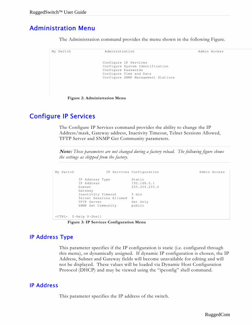
Administration Menu The Administration command provides the menu shown in the following Figure.
Configu
IP Addre
IP Addre
Figure 2: Administration Menu
My Switch Administration Admin Access Configure IP Services Configure System Identification Configure Passwords Configure Time and Date Configure SNMP Management Stations CTRL Z H l S Sh ll
re IP Services The Configure IP Services command provides the ability to change the IP Address/mask, Gateway address, Inactivity Timeout, Telnet Sessions Allowed, TFTP Server and SNMP Get Community parameters.
Note: These parameters are not changed during a factory reload. The following figure shows the settings as shipped from the factory.
Figure 3: IP Services Configuration Menu
My Switch IP Services Configuration Admin Access IP Address Type Static IP Address 192.168.0.1 Subnet 255.255.255.0 Gateway Inactivity Timeout 5 min Telnet Sessions Allowed 8 TFTP Server Get Only SNMP Get Community public <CTRL> Z-Help S-Shell
ss Type
This parameter specifies if the IP configuration is static (i.e. configured through this menu), or dynamically assigned. If dynamic IP configuration is chosen, the IP Address, Subnet and Gateway fields will become unavailable for editing and will not be displayed. These values will be loaded via Dynamic Host Configuration Protocol (DHCP) and may be viewed using the “ipconfig” shell command.
ss
This parameter specifies the IP address of the switch.
RuggedCom
Table Of Contents
Note: Changes to the IP Address take effect immediately upon being saved. Telnet connections in place at the time of an address change will be lost.
Subnet
This parameter specifies the subnet mask of the switch.
Gateway
This parameter specifies the gateway IP address. This is the address to use when forwarding packets to a network other than the one the switch belongs to. It is only required if you intend to manage the switch from a management station that is separated from the switch by a router.
Inactivity Timeout
This parameter specifies the amount of time after keystrokes have been pressed before a management connection will be automatically broken. A value of zero disables timeouts altogether.
Telnet Sessions
This parameter limits the number of Telnet sessions. A value of zero prevents any Telnet access.
Note: If you disable Inactivity Timeouts and reduce the number of Telnet sessions to one, you will not be able to connect via Telnet until your current connection closes.
TFTP Server
This parameter controls how a TFTP client can access the switches built-in TFTP server. A setting of “Disabled” prevents all access, “Get Only” allows retrieval of files and “Enabled” allows storing and retrieval of files.
SNMP Get Community
This string determines the community string that may be used by any management station for SNMP read-only access of settings. Delete this string if you wish to prevent read-only access.
RuggedCom 5
RuggedSwitch™ User Guide
Configuring System Identification The system identification is displayed in the sign-on screen and in the upper left hand corner of all RuggedSwitch™ menu screens. Setting the system identification can make it easier to identify the switches within your network.
Setting the location and contact fields can provide information about where the switch is located and who to contact in order to resolve problems.
Configure Passwords The guest, operator and admin passwords provide differing levels of access to the switch. Guest users can view most settings but may not change settings or run commands. Operators cannot change settings but can reset alarms, statistics and logs. Admin users can change settings and run commands.
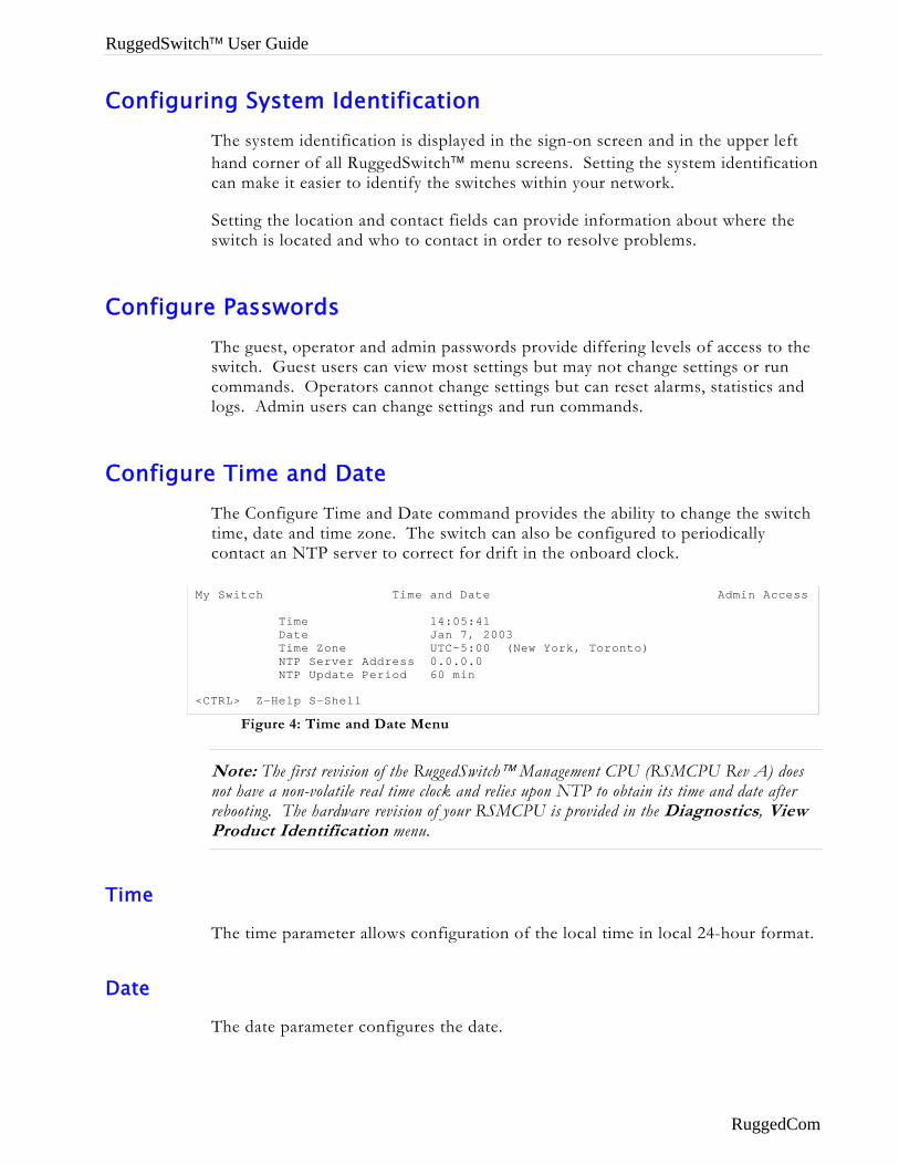
Configure Time and Date The Configure Time and Date command provides the ability to change the switch time, date and time zone. The switch can also be configured to periodically contact an NTP server to correct for drift in the onboard clock.
Figure 4: Time and Date Menu
Note: The first revision of the RuggedSwitch™ Management CPU (RSMCPU Rev A) does not have a non-volatile real time clock and relies upon NTP to obtain its time and date after rebooting. The hardware revision of your RSMCPU is provided in the Diagnostics, View Product Identification menu.
My Switch Time and Date Admin Access Time 14:05:41 Date Jan 7, 2003 Time Zone UTC-5:00 (New York, Toronto) NTP Server Address 0.0.0.0 NTP Update Period 60 min <CTRL> Z-Help S-Shell
Time
The time parameter allows configuration of the local time in local 24-hour format.
Date
The date parameter configures the date.
RuggedCom
Table Of Contents
Time Zone
The time zone setting allows for the conversion of UTC (Universal Coordinated Time) to local time.
NTP Server Address
This parameter specifies the IP address of the NTP (Network Time Protocol) server used to set the on-board real time clock. Programming an address of “0.0.0.0” disables the use of NTP. The current time setting will be overwritten at every NTP sync time interval, as specified by the NTP update period parameter.
Note: If your RuggedSwitch™ is not equipped with a real time clock, NTP is the only mechanism for obtaining the time after a start up.
NTP Update Period
This parameter determines how frequently the time is updated from the NTP server. If the update attempt fails the switch will make two more attempts (at one-minute intervals) after which an alarm is generated. The programmed update rate will then be resumed.
RuggedCom 7
RuggedSwitch™ User Guide
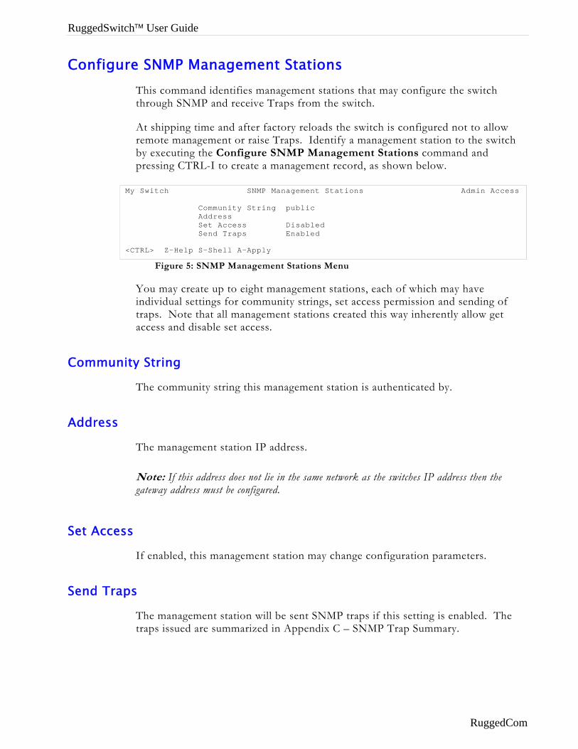
Configure SNMP Management Stations This command identifies management stations that may configure the switch through SNMP and receive Traps from the switch.
At shipping time and after factory reloads the switch is configured not to allow remote management or raise Traps. Identify a management station to the switch by executing the Configure SNMP Management Stations command and pressing CTRL-I to create a management record, as shown below.
Figure 5: SNMP Management Stations Menu
You may create up to eight management stations, each of which may have individual settings for community strings, set access permission and sending of traps. Note that all management stations created this way inherently allow get access and disable set access.
My Switch SNMP Management Stations Admin Access Community String public Address Set Access Disabled Send Traps Enabled <CTRL> Z-Help S-Shell A-Apply
Community String
The community string this management station is authenticated by.
Address
The management station IP address.
Note: If this address does not lie in the same network as the switches IP address then the gateway address must be configured.
Set Access
If enabled, this management station may change configuration parameters.
Send Traps
The management station will be sent SNMP traps if this setting is enabled. The traps issued are summarized in Appendix C – SNMP Trap Summary.
RuggedCom
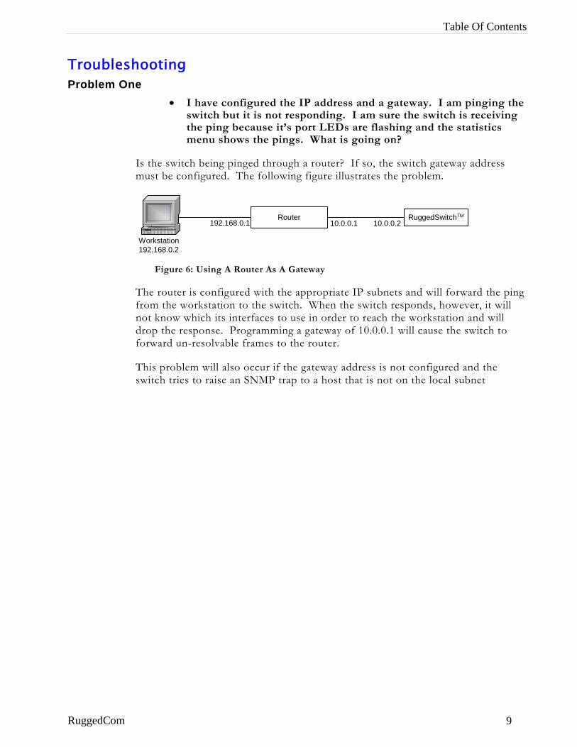
Table Of Contents
Troubleshooting Problem One
• I have configured the IP address and a gateway. I am pinging the switch but it is not responding. I am sure the switch is receiving the ping because it’s port LEDs are flashing and the statistics menu shows the pings. What is going on?
Is the switch being pinged through a router? If so, the switch gateway address must be configured. The following figure illustrates the problem.
Workstation192.168.0.2
Router RuggedSwitchTM
10.0.0.1 10.0.0.2192.168.0.1
Figure 6: Using A Router As A Gateway
The router is configured with the appropriate IP subnets and will forward the ping from the workstation to the switch. When the switch responds, however, it will not know which its interfaces to use in order to reach the workstation and will drop the response. Programming a gateway of 10.0.0.1 will cause the switch to forward un-resolvable frames to the router.
This problem will also occur if the gateway address is not configured and the switch tries to raise an SNMP trap to a host that is not on the local subnet
RuggedCom 9
RuggedSwitch™ User Guide
Chapter 2 - Configuring MAC Address Management
Introduction This chapter familiarizes the user with:
• Viewing learned MAC addresses
• Purging MAC Address Entries
• Configuring the switch MAC Address Aging time
• Configuring static MAC addresses
MAC Address Management Features
MAC Address management provides you with the following features:
• The ability to configure static MAC addresses.
• The ability to set the switch MAC address aging time
MAC Address Management Configuration
MAC Address Management Parameter Ranges & Default Settings Configuration Item Default Value Supported Values
Aging Time 300 seconds 15 to 800 seconds
MAC Address Tables Management Menu
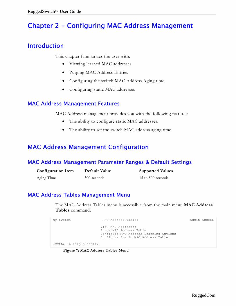
The MAC Address Tables menu is accessible from the main menu MAC Address Tables command.
Figure 7: MAC Address Tables Menu
My Switch MAC Address Tables Admin Access View MAC Addresses Purge MAC Address Table Configure MAC Address Learning Options Configure Static MAC Address Table <CTRL> Z-Help S-Shell>
RuggedCom
Chapter 2 - Configuring MAC Management
Viewing MAC Addresses
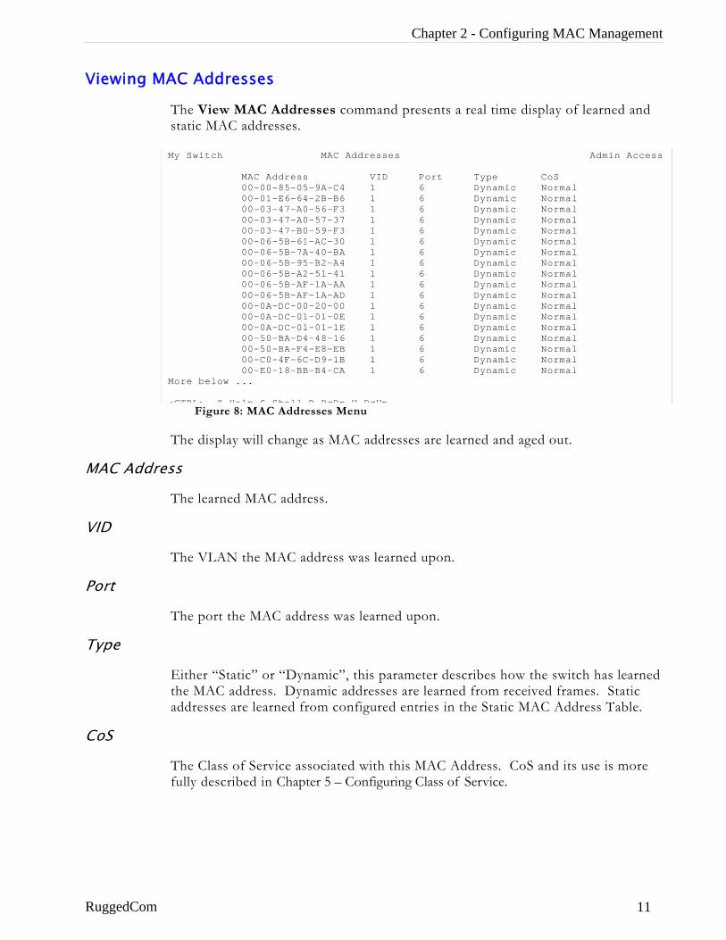
The View MAC Addresses command presents a real time display of learned and static MAC addresses.
M M <
MAC Addres
VID
Port
Type
CoS
RuggedCom
Figure 8: MAC Addresses Menu
y Switch MAC Addresses Admin Access
MAC Address VID Port Type CoS 00-00-85-05-9A-C4 1 6 Dynamic Normal 00-01-E6-64-2B-B6 1 6 Dynamic Normal 00-03-47-A0-56-F3 1 6 Dynamic Normal 00-03-47-A0-57-37 1 6 Dynamic Normal 00-03-47-B0-59-F3 1 6 Dynamic Normal 00-06-5B-61-AC-30 1 6 Dynamic Normal 00-06-5B-7A-40-BA 1 6 Dynamic Normal 00-06-5B-95-B2-A4 1 6 Dynamic Normal 00-06-5B-A2-51-41 1 6 Dynamic Normal 00-06-5B-AF-1A-AA 1 6 Dynamic Normal 00-06-5B-AF-1A-AD 1 6 Dynamic Normal 00-0A-DC-00-20-00 1 6 Dynamic Normal 00-0A-DC-01-01-0E 1 6 Dynamic Normal 00-0A-DC-01-01-1E 1 6 Dynamic Normal 00-50-BA-D4-48-16 1 6 Dynamic Normal 00-50-BA-F4-E8-EB 1 6 Dynamic Normal 00-C0-4F-6C-D9-1B 1 6 Dynamic Normal 00-E0-18-BB-B4-CA 1 6 Dynamic Normal ore below ...
CTRL> Z-Help S-Shell D-PgDn U-PgUp
The display will change as MAC addresses are learned and aged out.
s
The learned MAC address.
The VLAN the MAC address was learned upon.
The port the MAC address was learned upon.
Either “Static” or “Dynamic”, this parameter describes how the switch has learned the MAC address. Dynamic addresses are learned from received frames. Static addresses are learned from configured entries in the Static MAC Address Table.
The Class of Service associated with this MAC Address. CoS and its use is more fully described in Chapter 5 – Configuring Class of Service.
11
RuggedSwitch™ User Guide
Purge MAC Address Table
This command removes all dynamic entries from the MAC address table. The only negative impact of this operation is that it causes flooding while addresses are relearned.
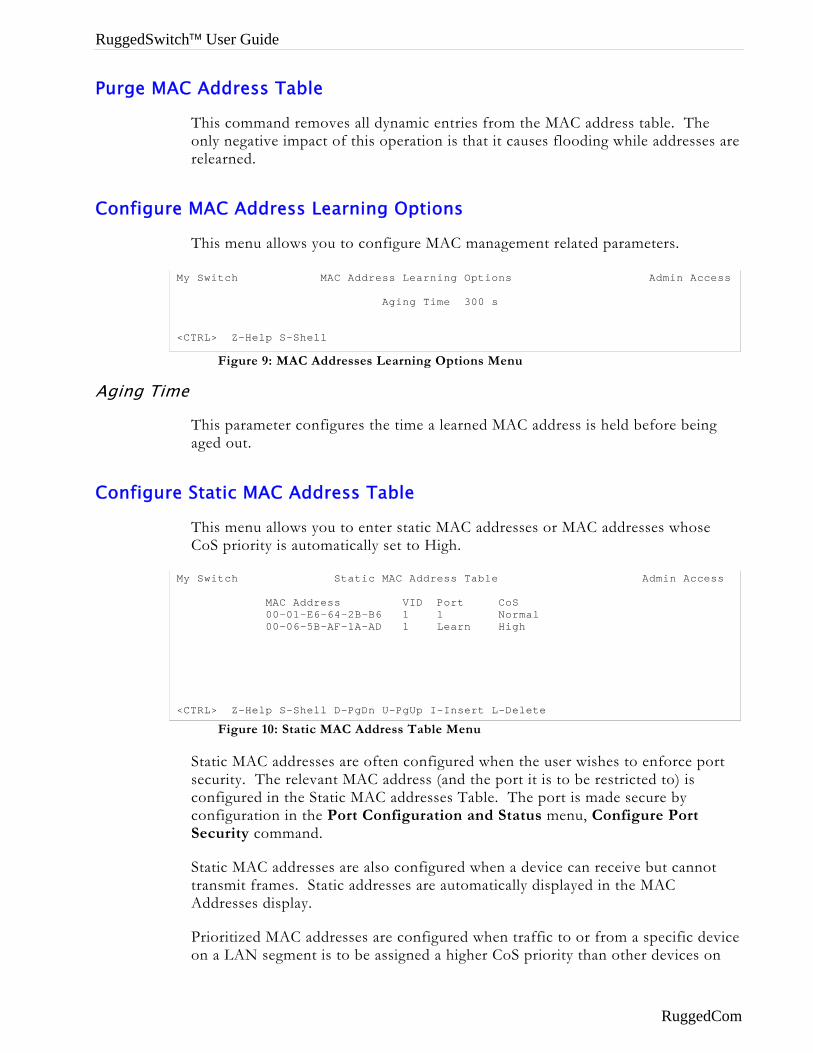
Configure MAC Address Learning Options
This menu allows you to configure MAC management related parameters.
Figure 9: MAC Addresses Learning Options Menu
Aging Time
This parameter configures the time a learned MAC address is held before being aged out.
Configure Static MAC Address Table
This menu allows you to enter static MAC addresses or MAC addresses whose CoS priority is automatically set to High.
Figure 10: Static MAC Address Table Menu
Static MAC addresses are often configured when the user wishes to enforce port security. The relevant MAC address (and the port it is to be restricted to) is configured in the Static MAC addresses Table. The port is made secure by configuration in the Port Configuration and Status menu, Configure Port Security command.
Static MAC addresses are also configured when a device can receive but cannot transmit frames. Static addresses are automatically displayed in the MAC Addresses display.
Prioritized MAC addresses are configured when traffic to or from a specific device on a LAN segment is to be assigned a higher CoS priority than other devices on
My Switch MAC Address Learning Options Admin Access Aging Time 300 s <CTRL> Z-Help S-Shell
My Switch Static MAC Address Table Admin Access MAC Address VID Port CoS 00-01-E6-64-2B-B6 1 1 Normal 00-06-5B-AF-1A-AD 1 Learn High <CTRL> Z-Help S-Shell D-PgDn U-PgUp I-Insert L-Delete
RuggedCom
Chapter 2 - Configuring MAC Management
that LAN segment. Prioritized addresses function much as regular dynamic addresses, appearing in the MAC Addresses display only while they are learned.
MAC Address
This parameter specifies the unicast address that is to be statically configured or prioritized.
VID
This parameter configures the VLAN upon which the MAC address operates.
Port
If a static MAC address is being constructed, enter the port number upon which the device with this address is located. If a prioritized address is being constructed set this parameter to “Learn”.
CoS (Class of Service)
Set this parameter to normal if you want the prioritized address to have a normal CoS priority or to high if you want the prioritized address to have a high CoS priority
RuggedCom 13
RuggedSwitch™ User Guide
Chapter 3 – Configuring the Ports
Introduction This chapter familiarizes the user with:
• Configuring port physical parameters
• Configuring link alarms/traps for the port
• Configuring rate limiting
• Configuring port security
• Using Port Mirroring
• Viewing the status of ports
• Resetting all or one port
• Using the Loss-of-Link Management feature
Port Features
10BaseT/100Base Interfaces • Uses RJ45 Connector
10BaseFL Interfaces • Multi-mode fiber (820nm) optical ports on 62.5µm cable, 2km distances
• Single-mode fiber (1310nm) optical ports on 9µm cable, 15km distances
• Uses ST Connector
• Support Far End Fault Indication (FEFI) through withholding of link pulses
100BaseFX Interfaces • Multi-mode fiber (1300nm) optical ports on 62.5µm cable, 2km distances
• Single-mode fiber (1310nm) optical ports on 9µm cable, 15km distances
• Multi-mode Uses MTRJ Connector, Single-mode Uses LC Connector
• Support Far End Fault Indication Through FEFI signal
All Interfaces • Port security
• Broadcast Rate Filtering
• Link based Alarms and Traps
RuggedCom
Chapter 3 – Configuring the Ports
• Port Latency: 10 Mbps - 16µs + frame time, 100 Mbps - 5µs + frame time
Port Applications
Port Security
Port Security provides the ability to filter or accept traffic from specific MAC addresses.
Port Security works by inspecting the source MAC addresses of received frames and validating them against the contents in the Static MAC Address Table (See Chapter 2 - Configuring MAC Address Management). Unauthorized frames will be filtered and, optionally, the port that receives the frame shutdown permanently or for a period of time. An alarm will be raised indicating the unauthorized MAC address (See Chapter 8 – Diagnostics).
Unicast frames to unknown destination addresses will not be flooded through secure ports.
The switch can also be programmed to learn and allow the first source MAC address encountered on the port. This feature provides a convenient means for network administrators to “capture” the appropriate secure addresses when turning up a port. The MAC address will be permanently added to the Static MAC Address Table.
Note: Port security is applied at the edge of the network in order to restrict admission to specific devices. Do not apply port security on core switch connections or where traffic types such as RSTP or IGMP are active.
Broadcast Rate Limiting
Broadcast rate filtering provides a means to limit the rate of broadcast frames accepted by each port.
Broadcast rate filtering limits the severity of broadcast storms.
RuggedCom 15
RuggedSwitch™ User Guide
Controller Protection Through Loss-of-Link Management
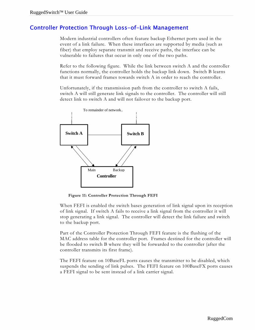
Modern industrial controllers often feature backup Ethernet ports used in the event of a link failure. When these interfaces are supported by media (such as fiber) that employ separate transmit and receive paths, the interface can be vulnerable to failures that occur in only one of the two paths.
Refer to the following figure. While the link between switch A and the controller functions normally, the controller holds the backup link down. Switch B learns that it must forward frames towards switch A in order to reach the controller.
Unfortunately, if the transmission path from the controller to switch A fails, switch A will still generate link signals to the controller. The controller will still detect link to switch A and will not failover to the backup port.
Controller
Switch A
Switch B
Main Backup
To remainder of network..
Figure 11: Controller Protection Through FEFI
When FEFI is enabled the switch bases generation of link signal upon its reception of link signal. If switch A fails to receive a link signal from the controller it will stop generating a link signal. The controller will detect the link failure and switch to the backup port.
Part of the Controller Protection Through FEFI feature is the flushing of the MAC address table for the controller port. Frames destined for the controller will be flooded to switch B where they will be forwarded to the controller (after the controller transmits its first frame).
The FEFI feature on 10BaseFL ports causes the transmitter to be disabled, which suspends the sending of link pulses. The FEFI feature on 100BaseFX ports causes a FEFI signal to be sent instead of a link carrier signal.
RuggedCom

Chapter 3 – Configuring the Ports
Using Port Mirroring
Introduction
Port mirroring is a management tool in which all traffic on a designated port is copied (or mirrored) to a target port. If a protocol analyzer is attached to the target port, the traffic stream of valid frames on any source port is made available for analysis.
Note: Invalid frames received on the source port will not be mirrored. These include CRC errors, oversize and undersize packets, fragments, jabbers, collisions, late collisions and dropped events).
Configuring Port Mirroring
Select a target port that has a higher speed than the source port. Mirroring a 100 Mbps port onto a 10 Mbps port may result in an improperly mirrored stream.
Frames will be dropped if the full duplex rate of frames on the source port exceeds the transmission speed of the target port. Since both transmitted and received frames on the source port are mirrored to the target port, frames will be discarded if the sum traffic exceeds the target port’s transmission rate. This problem reaches its extreme in the case where traffic on a 100 Mbps full duplex port is mirrored onto a 10 Mbps half duplex port.
A limitation of port mirroring occurs with multicast traffic. Multicast traffic will be mirrored onto the target port only if the target port is a member of the same VLANs as the source port.
Limitations of port mirroring occur with VLAN traffic. If the port selected as the source port receives an untagged frame that will be forwarded to a tagged port, the target port will incorrectly show the frame as having been received tagged.
If the port selected as the port mirroring target is configured as a tagged edge VLAN port, all untagged frames received by and copied from the source port will be sent tagged with the native VLAN for the source port. If the port selected as the target is configured as an untagged edge VLAN port, all tags in frames copied from the source port will be removed before transmission on the target port.
A further limitation of port mirroring is that traffic originated by the switch, such as ping requests, may not be mirrored.
Port Configuration And Status
RuggedCom 17
RuggedSwitch™ User Guide
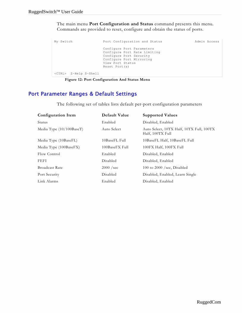
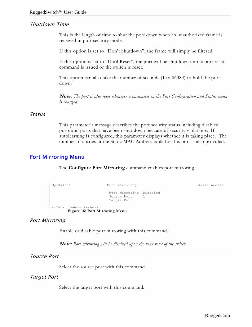
The main menu Port Configuration and Status command presents this menu. Commands are provided to reset, configure and obtain the status of ports.
Figure 12: Port Configuration And Status Menu
My Switch Port Configuration and Status Admin Access Configure Port Parameters Configure Port Rate Limiting Configure Port Security Configure Port Mirroring View Port Status Reset Port(s) <CTRL> Z-Help S-Shell
Port Parameter Ranges & Default Settings
The following set of tables lists default per-port configuration parameters
Configuration Item Default Value Supported Values
Status Enabled Disabled, Enabled
Media Type (10/100BaseT) Auto Select Auto Select, 10TX Half, 10TX Full, 100TX Half, 100TX Full
Media Type (10BaseFL) 10BaseFL Full 10BaseFL Half, 10BaseFL Full
Media Type (100BaseFX) 100BaseFX Full 100FX Half, 100FX Full
Flow Control Enabled Disabled, Enabled
FEFI Disabled Disabled, Enabled
Broadcast Rate 2000 /sec 100 to 2000 /sec, Disabled
Port Security Disabled Disabled, Enabled, Learn Single
Link Alarms Enabled Disabled, Enabled
RuggedCom
Chapter 3 – Configuring the Ports
Port Configuration Menu
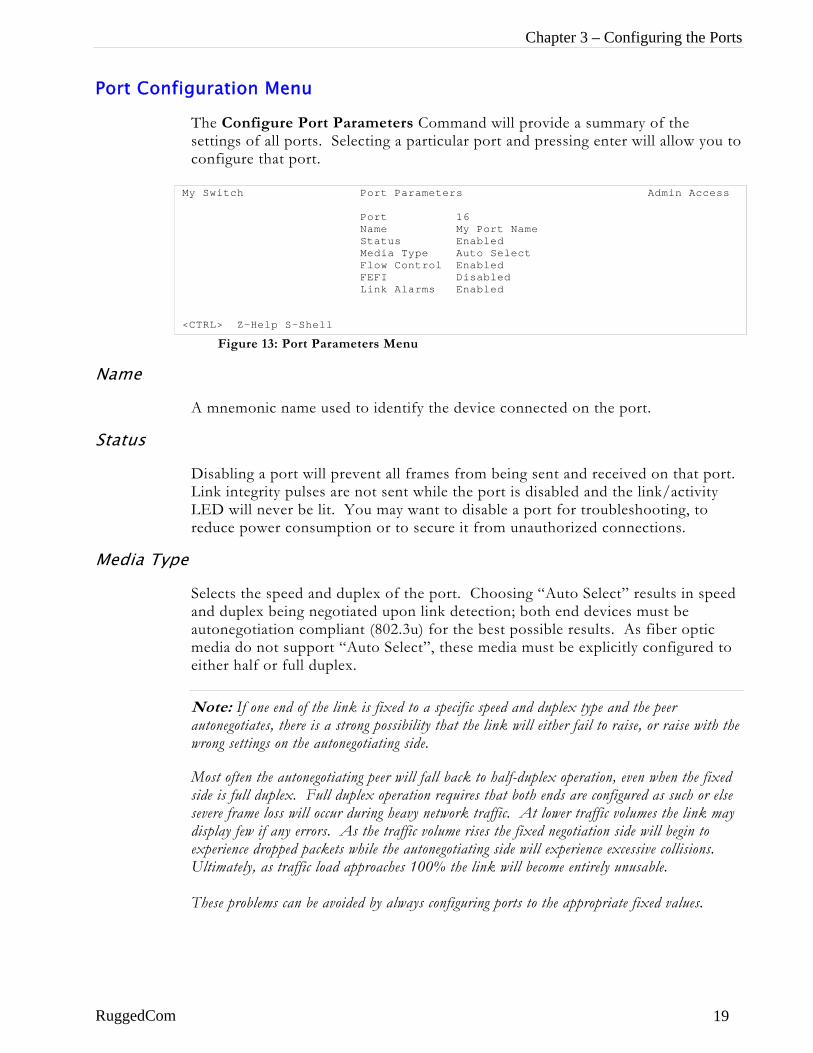
The Configure Port Parameters Command will provide a summary of the settings of all ports. Selecting a particular port and pressing enter will allow you to configure that port.
Figure 13: Port Parameters Menu
Name
A mnemonic name used to identify the device connected on the port.
Status
Disabling a port will prevent all frames from being sent and received on that port. Link integrity pulses are not sent while the port is disabled and the link/activity LED will never be lit. You may want to disable a port for troubleshooting, to reduce power consumption or to secure it from unauthorized connections.
Media Type
Selects the speed and duplex of the port. Choosing “Auto Select” results in speed and duplex being negotiated upon link detection; both end devices must be autonegotiation compliant (802.3u) for the best possible results. As fiber optic media do not support “Auto Select”, these media must be explicitly configured to either half or full duplex.
Note: If one end of the link is fixed to a specific speed and duplex type and the peer autonegotiates, there is a strong possibility that the link will either fail to raise, or raise with the wrong settings on the autonegotiating side.
Most often the autonegotiating peer will fall back to half-duplex operation, even when the fixed side is full duplex. Full duplex operation requires that both ends are configured as such or else severe frame loss will occur during heavy network traffic. At lower traffic volumes the link may display few if any errors. As the traffic volume rises the fixed negotiation side will begin to experience dropped packets while the autonegotiating side will experience excessive collisions. Ultimately, as traffic load approaches 100% the link will become entirely unusable. These problems can be avoided by always configuring ports to the appropriate fixed values.
My Switch Port Parameters Admin Access Port 16 Name My Port Name Status Enabled Media Type Auto Select Flow Control Enabled FEFI Disabled Link Alarms Enabled <CTRL> Z-Help S-Shell
RuggedCom 19
RuggedSwitch™ User Guide
Flow Control
Flow Control is useful for preventing frame loss during times of severe network traffic. Examples of this include multiple source ports concentrating to a single destination port or a higher speed port bursting to a lower speed port.
When the port is half-duplex it is accomplished using “backpressure” where the switch simulates collisions causing the sending device to retry transmissions according to the Ethernet backoff algorithm. When the port is full duplex it is accomplished using PAUSE frames which causes the sending device to stop transmitting for a period of time.
FEFI
Enabling Far End Fault Indication (FEFI) inhibits transmitting link integrity pulses when the receive link has failed. This allows the device at far end to detect link failure under all circumstances.
Note: This feature must not be enabled at both end of a link.
Link Alarms
Enabling link alarms will cause alarms and SNMP linkUp and linkDown traps to be sent for the port.
Port Rate Limiting Menu
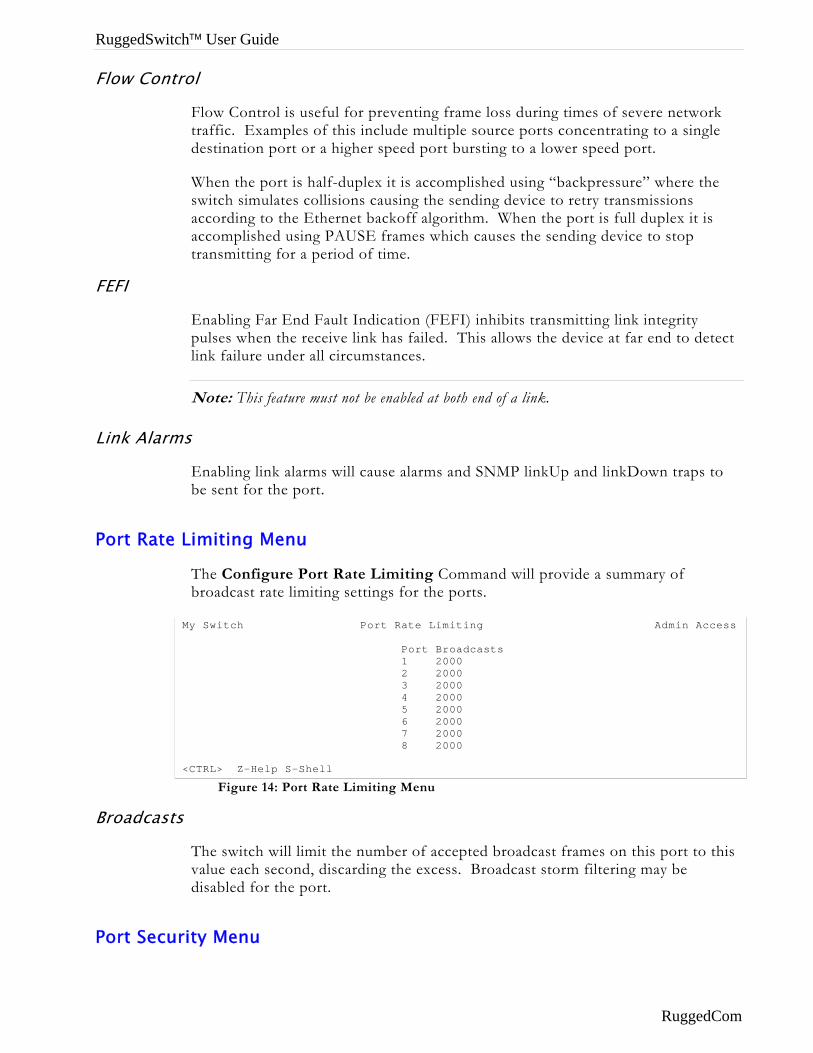
The Configure Port Rate Limiting Command will provide a summary of broadcast rate limiting settings for the ports.
Figure 14: Port Rate Limiting Menu
My Switch Port Rate Limiting Admin Access Port Broadcasts 1 2000 2 2000 3 2000 4 2000 5 2000 6 2000 7 2000 8 2000 <CTRL> Z-Help S-Shell
Broadcasts
The switch will limit the number of accepted broadcast frames on this port to this value each second, discarding the excess. Broadcast storm filtering may be disabled for the port.
Port Security Menu
RuggedCom
Chapter 3 – Configuring the Ports
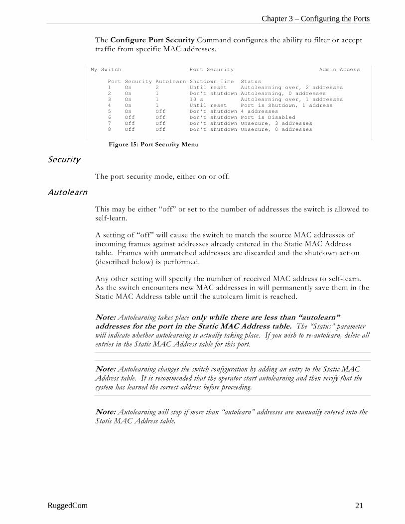
The Configure Port Security Command configures the ability to filter or accept traffic from specific MAC addresses.
M
Security
Autolearn
RuggedCom
Figure 15: Port Security Menu
y Switch Port Security Admin Access
Port Security Autolearn Shutdown Time Status 1 On 2 Until reset Autolearning over, 2 addresses 2 On 1 Don't shutdown Autolearning, 0 addresses 3 On 1 10 s Autolearning over, 1 addresses 4 On 1 Until reset Port is Shutdown, 1 address 5 On Off Don't shutdown 4 addresses 6 Off Off Don't shutdown Port is Disabled 7 Off Off Don't shutdown Unsecure, 3 addresses 8 Off Off Don't shutdown Unsecure, 0 addresses
CTRL Z H l S Sh ll
The port security mode, either on or off.
This may be either “off” or set to the number of addresses the switch is allowed to self-learn.
A setting of “off” will cause the switch to match the source MAC addresses of incoming frames against addresses already entered in the Static MAC Address table. Frames with unmatched addresses are discarded and the shutdown action (described below) is performed.
Any other setting will specify the number of received MAC address to self-learn. As the switch encounters new MAC addresses in will permanently save them in the Static MAC Address table until the autolearn limit is reached.
Note: Autolearning takes place only while there are less than “autolearn” addresses for the port in the S at c MAC Address table The “Status” parameter will indicate whether autolearning is actually taking place. If you wish to re-autolearn, delete all entries in the Static MAC Address table for this port.
t i .
Note: Autolearning changes the switch configuration by adding an entry to the Static MAC Address table. It is recommended that the operator start autolearning and then verify that the system has learned the correct address before proceeding. Note: Autolearning will stop if more than “autolearn” addresses are manually entered into the Static MAC Address table.
21
RuggedSwitch™ User Guide
Shutdown Time
This is the length of time to shut the port down when an unauthorized frame is received in port security mode.
If this option is set to “Don’t Shutdown”, the frame will simply be filtered.
If this option is set to “Until Reset”, the port will be shutdown until a port reset command is issued or the switch is reset.
This option can also take the number of seconds (1 to 86384) to hold the port down.
Note: The port is also reset whenever a parameter in the Port Configuration and Status menu is changed.
Status
This parameter’s message describes the port security status including disabled ports and ports that have been shut down because of security violations. If autolearning is configured, this parameter displays whether it is taking place. The number of entries in the Static MAC Address table for this port is also provided.
Port Mirroring Menu
The Configure Port Mirroring command enables port mirroring.
Figure 16: Port Mirroring Menu
My Switch Port Mirroring Admin Access Port Mirroring Disabled Source Port 1 Target Port 1 <CTRL> Z-Help S-Shell
Port Mirroring
Enable or disable port mirroring with this command.
Note: Port mirroring will be disabled upon the next reset of the switch.
Source Port
Select the source port with this command.
Target Port
Select the target port with this command.
RuggedCom
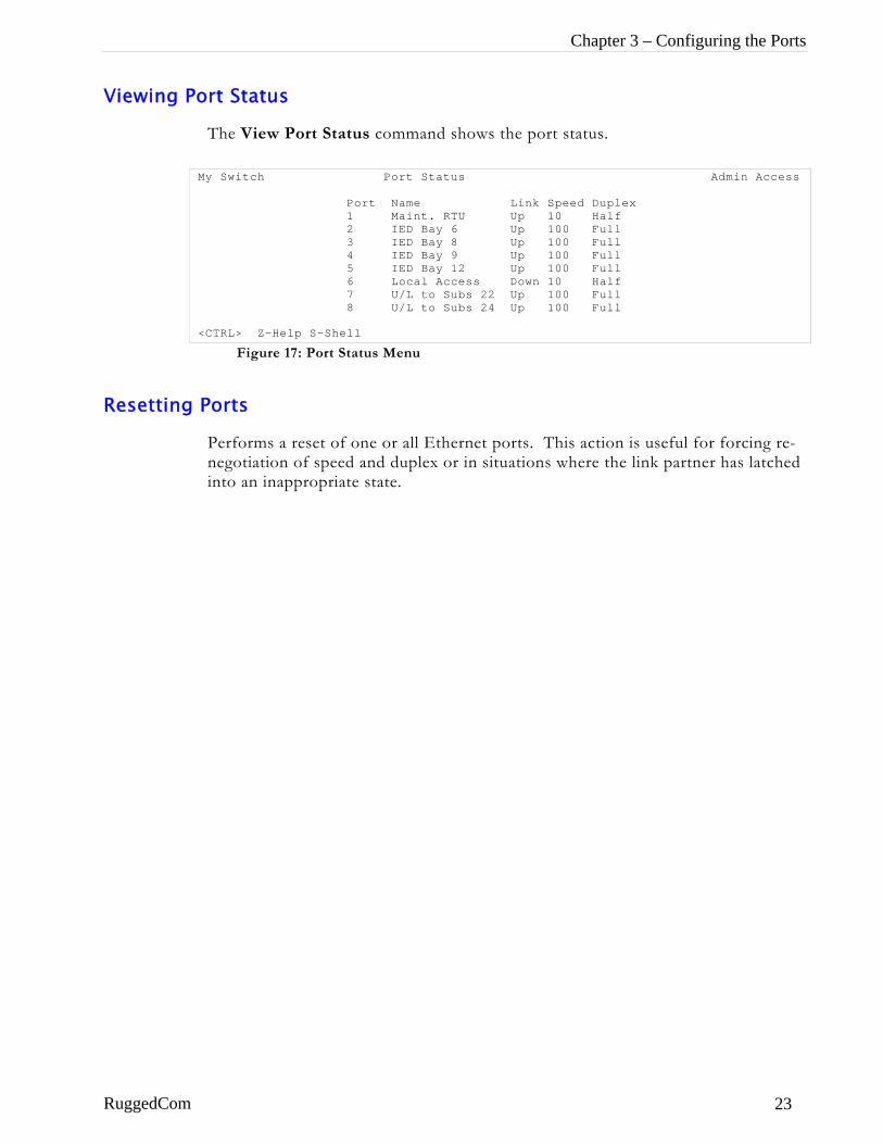
Chapter 3 – Configuring the Ports
Viewing Port Status
The View Port Status command shows the port status.
Figure 17: Port Status Menu
My Switch Port Status Admin Access Port Name Link Speed Duplex 1 Maint. RTU Up 10 Half 2 IED Bay 6 Up 100 Full 3 IED Bay 8 Up 100 Full 4 IED Bay 9 Up 100 Full 5 IED Bay 12 Up 100 Full 6 Local Access Down 10 Half 7 U/L to Subs 22 Up 100 Full 8 U/L to Subs 24 Up 100 Full <CTRL> Z-Help S-Shell
Resetting Ports
Performs a reset of one or all Ethernet ports. This action is useful for forcing re-negotiation of speed and duplex or in situations where the link partner has latched into an inappropriate state.
RuggedCom 23
RuggedSwitch™ User Guide
Troubleshooting Problem One
• One of my links seems to be fine at low traffic levels, but starts to fail as traffic rates increase.
• One of my links pings OK but has problems with FTP/SQL/HTTP/…
A possible cause of intermittent operation is that of an autonegotiation mismatch. If one end of the link is fixed to full duplex and the peer autonegotiates, the autonegotiating end falls back to half-duplex operation. At lower traffic volumes the link may display few if any errors. As the traffic volume rises the fixed negotiation side will begin to experience dropped packets while the autonegotiating side will experience collisions. Ultimately, as traffic loads approach 100% the link will become entirely unusable.
Note: The ping command with flood options is a useful tool for testing commissioned links. The command “ping 192.168.0.1 500 2” can be used to issue 500 pings each separated by 2 milliseconds to the next switch. If the link used is of high quality then no pings should be lost and the average round trip time should be small.
Problem Two • I am trying to use the FEFI protection feature but my links won’t
even come up.
Is it possible that the peer also has FEFI enabled? If both sides of the link have FEFI enabled then both sides will withhold link signal generation from each other.
Problem Three • I programmed the broadcast rate to 100 frames/sec on all my
ports. Why can I see more than 100 frames/sec coming out my ports?
The broadcast rate applies only to admission of frames. An eight-port switch with broadcast rate filtering set to 100 frames/sec could conceivably forward 700 broadcast frames/sec out a port.
RuggedCom
Chapter 4 – Configuring VLANs
Chapter 4 – Configuring VLANs
Introduction This chapter familiarizes the user with:
• VLAN Terminology and Issues
• VLANs and their relationship to protocols such as IGMP
• Planning VLAN networks
• Configuring VLANs
• Viewing VLAN status and statistics
• Troubleshooting VLANs
VLAN Features
RuggedCom VLANs provide you with the following features:
• Per Port :
• Native VLAN is configurable. • Modes of operation tailored to edge devices (such as a PC or IED) and to
network switch interconnections. • A default port setting that ensures configuration-free connectivity in certain
scenarios. • The ability to force either tagged or untagged operation on the native VLAN
• Per VLAN :
• VLAN Name, • IGMP • Ability to exclude ports from the VLAN.
• Per switch :
• Assignment of up to 64 VLANs (in the range of 1 to 1000).
RuggedCom 25
RuggedSwitch™ User Guide
VLAN Concepts And Issues
VLANs and Tags
A virtual LAN or VLAN is a group of devices on one or more LAN segments that communicate as if they were attached to the same physical LAN segment. VLANs are extremely flexible because they are based on logical instead of physical connections.
When VLANs are introduced, all traffic in the network must belong to one or another VLAN. Traffic on one VLAN cannot pass to another, except through an intranetwork router or layer 3 switch.
A VLAN tag is the identification information that is present in frames in order to support VLAN operation.
Tagged vs. Untagged Frames
Tagged frames are frames with 802.1q (VLAN) tags that specify a valid VLAN identifier (VID). Untagged frames are frames without tags or frames that carry 802.1p (Prioritization) tags having prioritization information.
When a switch receives a tagged frame it extracts the VID. If the VID is not allowed on the port the frame was received upon, the frame will be discarded. If the VID is acceptable the frame will be forwarded to other ports in the same VLAN.
Native VLAN
Each port is assigned a native VLAN number, the Port VLAN ID (PVID). When an untagged frame is received, it is tagged with the native VLAN.
By default, when the switch transmits a frame on the native VLAN it removes the tag before doing so. The switch can be configured to transmit frames on the native VLAN tagged.
Management VLAN
Management traffic, like all traffic on the network, must belong to a specific VLAN. RuggedCom switch management is always part of VLAN 1. This VLAN is the native VLAN by default.
RuggedCom

Chapter 4 – Configuring VLANs
Edge And Trunk Port Types
Each port can be configured to take on a type of Edge or Trunk.
An Edge port attaches to a single end device (such as a PC or IED) and carries traffic on a single pre-configured VLAN.
Trunk ports are part of the network and carry traffic for all VLANs between switches. Trunk ports must be manually programmed with the VLANs to be supported.
Forbidden Port Lists
Each VLAN can be configured to exclude ports from membership in the VLAN.
VLAN Based Services
IGMP Snooping
The Internet Group Management Protocol (IGMP) provides the ability for IP hosts and workstations to report their multicast group memberships to routers. The switch can “snoop” or monitor these messages in order to restrict multicast traffic streams to only the necessary parts of the network. IGMP snooping is activated on a per-VLAN basis. See “Chapter 7 – Configuring Multicast Filtering” for information on configuring IGMP snooping.
VLAN Applications
Traffic Domain Isolation
VLANs are most often used for their ability to restrict traffic flows between groups of devices.
Unnecessary broadcast traffic can be restricted to the VLAN that requires it. Broadcast storms in one VLAN need not affect users in other VLANs.
Hosts on one VLAN can be prevented from accidentally or deliberately assuming the IP address of a host on another VLAN.
The use of creative bridge filtering and multiple VLANs can carve seemingly unified IP subnets into multiple regions policed by different security/access policies.
Multi-VLAN hosts can assign different traffic types to different VLANs.
RuggedCom 27
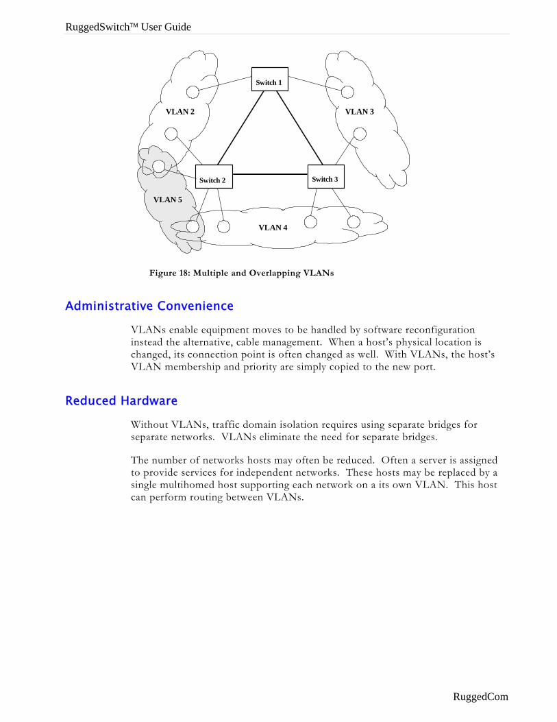
RuggedSwitch™ User Guide
Switch 2
Switch 3
VLAN 3
VLAN 4
VLAN 5
VLAN 2
Switch 1
Figure 18: Multiple and Overlapping VLANs
Administrative Convenience
VLANs enable equipment moves to be handled by software reconfiguration instead the alternative, cable management. When a host’s physical location is changed, its connection point is often changed as well. With VLANs, the host’s VLAN membership and priority are simply copied to the new port.
Reduced Hardware
Without VLANs, traffic domain isolation requires using separate bridges for separate networks. VLANs eliminate the need for separate bridges.
The number of networks hosts may often be reduced. Often a server is assigned to provide services for independent networks. These hosts may be replaced by a single multihomed host supporting each network on a its own VLAN. This host can perform routing between VLANs.
RuggedCom
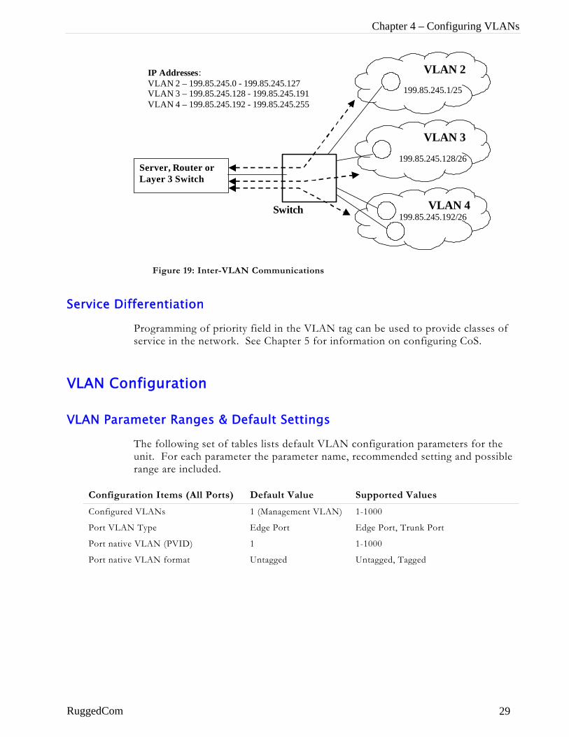
Chapter 4 – Configuring VLANs
VLAN 3
VLAN 4
VLAN 2
199.85.245.1/25
199.85.245.128/26
199.85.245.192/26
IP Addresses: VLAN 2 – 199.85.245.0 - 199.85.245.127 VLAN 3 – 199.85.245.128 - 199.85.245.191 VLAN 4 – 199.85.245.192 - 199.85.245.255
Server, Router or Layer 3 Switch
Switch
Figure 19: Inter-VLAN Communications
Service Differentiation
Programming of priority field in the VLAN tag can be used to provide classes of service in the network. See Chapter 5 for information on configuring CoS.
VLAN Configuration
VLAN Parameter Ranges & Default Settings
The following set of tables lists default VLAN configuration parameters for the unit. For each parameter the parameter name, recommended setting and possible range are included.
Configuration Items (All Ports) Default Value Supported Values
Configured VLANs 1 (Management VLAN) 1-1000
Port VLAN Type Edge Port Edge Port, Trunk Port
Port native VLAN (PVID) 1 1-1000
Port native VLAN format Untagged Untagged, Tagged
RuggedCom 29
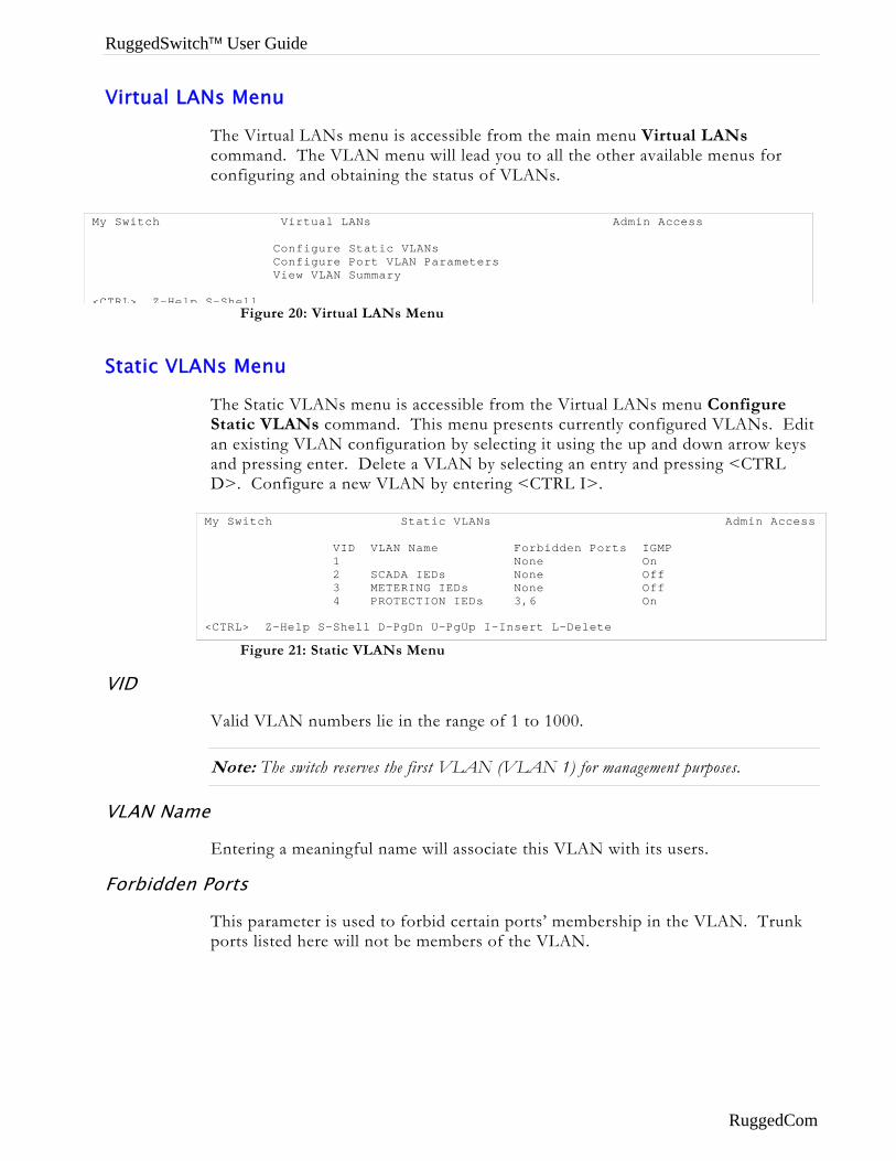
RuggedSwitch™ User Guide
Virtual LANs Menu
The Virtual LANs menu is accessible from the main menu Virtual LANs command. The VLAN menu will lead you to all the other available menus for configuring and obtaining the status of VLANs.
M <
Figure 20: Virtual LANs Menu
y Switch Virtual LANs Admin Access
Configure Static VLANs Configure Port VLAN Parameters View VLAN Summary
CTRL> Z-Help S-Shell
Static VLANs Menu
The Static VLANs menu is accessible from the Virtual LANs menu Configure Static VLANs command. This menu presents currently configured VLANs. Edit an existing VLAN configuration by selecting it using the up and down arrow keys and pressing enter. Delete a VLAN by selecting an entry and pressing <CTRL D>. Configure a new VLAN by entering <CTRL I>.
Figure 21: Static VLANs Menu
My Switch Static VLANs Admin Access VID VLAN Name Forbidden Ports IGMP 1 None On 2 SCADA IEDs None Off 3 METERING IEDs None Off 4 PROTECTION IEDs 3,6 On <CTRL> Z-Help S-Shell D-PgDn U-PgUp I-Insert L-Delete
VID
Valid VLAN numbers lie in the range of 1 to 1000.
Note: The switch reserves the first VLAN (VLAN 1) for management purposes.
VLAN Name
Entering a meaningful name will associate this VLAN with its users.
Forbidden Ports
This parameter is used to forbid certain ports’ membership in the VLAN. Trunk ports listed here will not be members of the VLAN.
RuggedCom
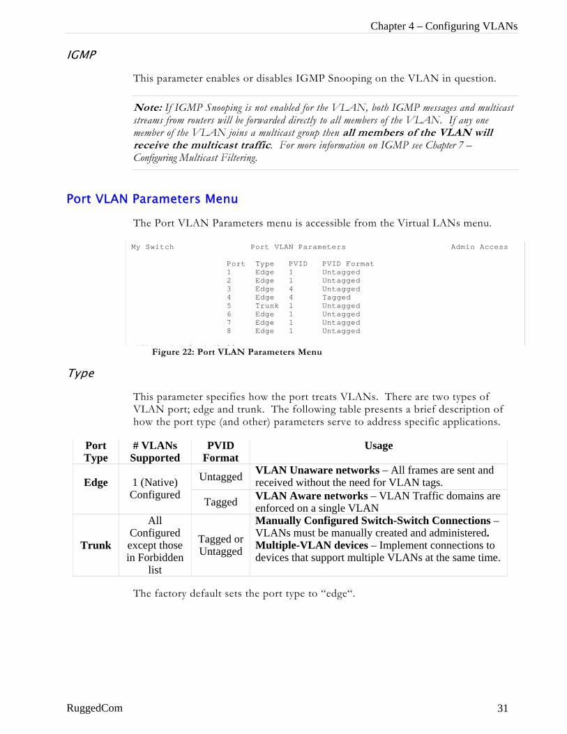
Chapter 4 – Configuring VLANs
IGMP
This parameter enables or disables IGMP Snooping on the VLAN in question.
Note: If IGMP Snooping is not enabled for the VLAN, both IGMP messages and multicast streams from routers will be forwarded directly to all members of the VLAN. If any one member of the VLAN joins a multicast group then all members of the VLAN will receive the multicast traffic. For more information on IGMP see Chapter 7 – Configuring Multicast Filtering.
Port VLAN Parameters Menu
The Port VLAN Parameters menu is accessible from the Virtual LANs menu.
M
Type
Port Type S
Edge C
Trunk Cein
RuggedCom
Figure 22: Port VLAN Parameters Menu
y Switch Port VLAN Parameters Admin Access
Port Type PVID PVID Format 1 Edge 1 Untagged 2 Edge 1 Untagged 3 Edge 4 Untagged 4 Edge 4 Tagged 5 Trunk 1 Untagged 6 Edge 1 Untagged 7 Edge 1 Untagged 8 Edge 1 Untagged
CTRL Z H l S Sh ll
This parameter specifies how the port treats VLANs. There are two types of VLAN port; edge and trunk. The following table presents a brief description of how the port type (and other) parameters serve to address specific applications.
# VLANs upported
PVID Format
Usage
Untagged VLAN Unaware networks – All frames are sent and received without the need for VLAN tags. 1 (Native)
onfigured Tagged VLAN Aware networks – VLAN Traffic domains are enforced on a single VLAN
All onfigured
xcept those Forbidden
list
Tagged or Untagged
Manually Configured Switch-Switch Connections – VLANs must be manually created and administered. Multiple-VLAN devices – Implement connections to devices that support multiple VLANs at the same time.
The factory default sets the port type to “edge“.
31
RuggedSwitch™ User Guide
Edge Type
An edge port is always a member of only one VLAN, the native VLAN (often called the port VLAN or PVID).
Use an edge port with PVID Format set to “tagged” when you need to service VLAN aware equipments and with PVID Format set to “untagged” when you need to service non-VLAN aware equipments.
Untagged frames received on edge ports will be forwarded to the network using the port's configured native VLAN.
Tagged frames received on edge ports will be forwarded to the network only if the tag is the same as the configured native VLAN (otherwise the frame will be discarded).
Frames transmitted out the port will be tagged with the native VLAN or sent untagged depending upon the PVID format parameter (see “PVID Format” below).
Trunk Type
Trunk ports are automatically members of all VLANs and implement switch-to-switch connections.
The switch can “pass through” traffic, forwarding frames received on one trunk port out another trunk port. The trunk ports must be members of all the VLANs the “pass through” traffic is part of, even if none of those VLANs are used on edge ports.
Untagged frames received on trunk ports will be forwarded using the port's native VLAN.
Frames transmitted out the port on the native VLAN will be tagged or untagged depending upon the PVID format (see below). Frames on other VLANs are always sent tagged.
Note: Sometimes it may be desirable to manually restrict the traffic on the trunk to a certain group of VLANs, for example when: the trunk connects to a device (such as a layer 3 router) that supports a subset of the available VLANs. Traffic may be manually restricted on trunk ports through the “Forbidden Ports” parameter (See “Static VLANs Menu” above).
RuggedCom
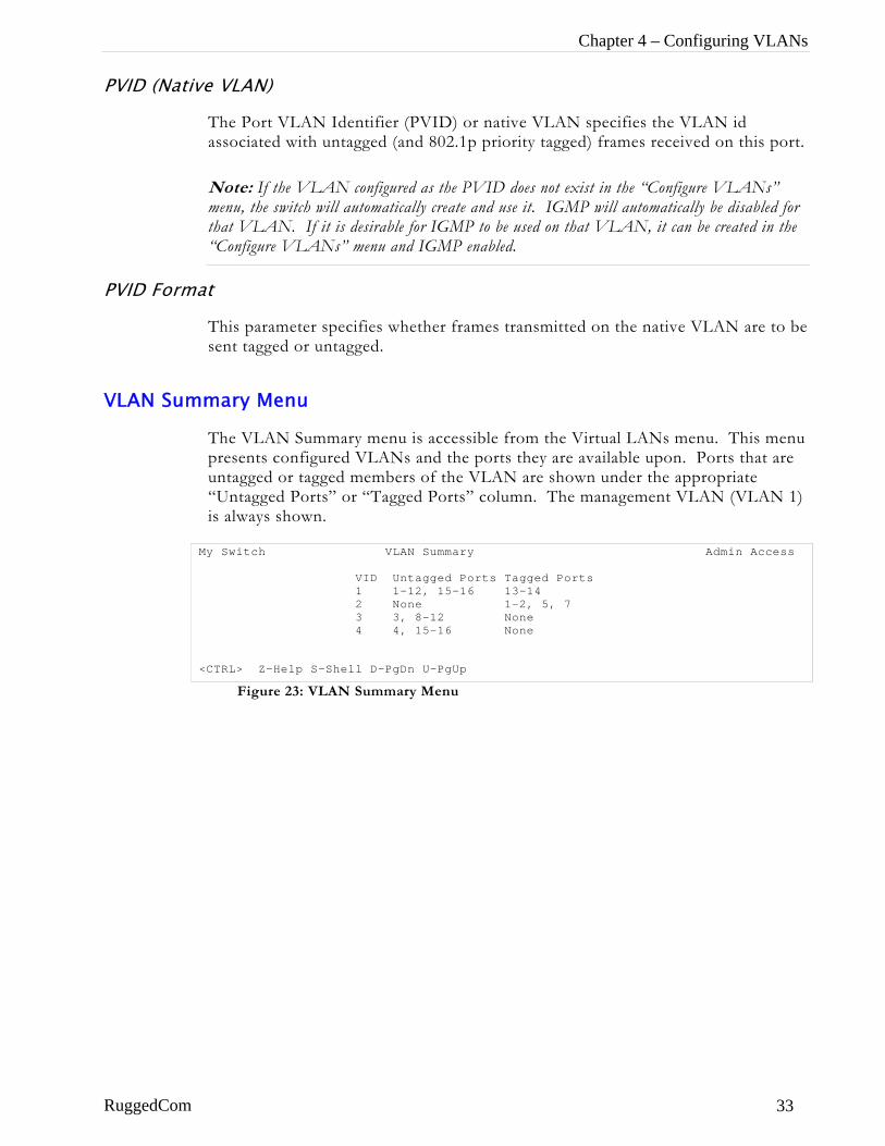
Chapter 4 – Configuring VLANs
PVID (Native VLAN)
The Port VLAN Identifier (PVID) or native VLAN specifies the VLAN id associated with untagged (and 802.1p priority tagged) frames received on this port.
Note: If the VLAN configured as the PVID does not exist in the “Configure VLANs” menu, the switch will automatically create and use it. IGMP will automatically be disabled for that VLAN. If it is desirable for IGMP to be used on that VLAN, it can be created in the “Configure VLANs” menu and IGMP enabled.
PVID Format
This parameter specifies whether frames transmitted on the native VLAN are to be sent tagged or untagged.
VLAN Summary Menu
The VLAN Summary menu is accessible from the Virtual LANs menu. This menu presents configured VLANs and the ports they are available upon. Ports that are untagged or tagged members of the VLAN are shown under the appropriate “Untagged Ports” or “Tagged Ports” column. The management VLAN (VLAN 1) is always shown.
Figure 23: VLAN Summary Menu
My Switch VLAN Summary Admin Access VID Untagged Ports Tagged Ports 1 1-12, 15-16 13-14 2 None 1-2, 5, 7 3 3, 8-12 None 4 4, 15-16 None <CTRL> Z-Help S-Shell D-PgDn U-PgUp
RuggedCom 33
RuggedSwitch™ User Guide
Troubleshooting Problem One
• I don’t need VLANs at all. How do I turn them off?
Simply leave all ports set to type “Edge” and leave the native VLAN set to 1. This is the default configuration for the switch.
Problem Two • I have added two VLANs 2 and 3. I made a number of ports
members of these VLANS. Now I need some of the devices in one VLAN send messages to some devices in the other VLAN.
If the devices need to communicate at the physical address layer, they must be members of the same VLAN. If they can communicate in a layer 3 fashion (i.e. using a protocol such as IP or IPX) you can use a router. The router will treat each VLAN as a separate interface, which will have its own associated IP address space.
RuggedCom
Chapter 5 – Configuring Class of Service
Chapter 5 – Configuring Class of Service
Introduction to CoS This chapter familiarizes the user with using the Class of Service feature.
CoS Features
RuggedSwitch™ CoS provide you with the following features:
• Ability to prioritize traffic statically by port.
• Ability to prioritize traffic by the priority field in 802.1p and 802.1q tags.
• Ability to prioritize traffic based on its source or destination MAC address.
• Ability to prioritize traffic by the TOS field in the IP header.
• Ability to set the 802.1Q access priority from an established CoS.
CoS Concepts And Issues
CoS Operation
CoS provides the ability to expedite the transmission of certain frames and port traffic over others. The CoS of a frame can take on one of two values, either normal or high. The default policies of the switch enforce a normal CoS for all traffic.
Note that CoS is only used internally by the switch, but may be conveyed externally by mapping the CoS to the priority field in the 802.1Q tags of outgoing frames.
The CoS feature has two main phases, inspection and forwarding.
Inspection Phase
In the inspection phase the CoS priority of a received frame is determined from:
• The priority field in 802.1P and 802.1Q tags
• The Differentiated Services Code Point (DSCP) component of the Type Of Service (TOS) field, if the frame is IP.
• The default CoS for the port.
• A specific CoS based upon the source and destination MAC address (as set in the Configure Static MAC Address Table menu).
RuggedCom 35
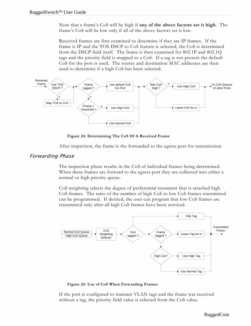
RuggedSwitch™ User Guide
Note that a frame’s CoS will be high if any of the above factors set it high. The frame’s CoS will be low only if all of the above factors set it low.
Received frames are first examined to determine if they are IP frames. If the frame is IP and the TOS DSCP to CoS feature is selected, the CoS is determined from the DSCP field itself. The frame is then examined for 802.1P and 802.1Q tags and the priority field is mapped to a CoS. If a tag is not present the default CoS for the port is used. The source and destination MAC addresses are then used to determine if a high CoS has been selected.
Use default CoSFor Port
Priority >Threshold ?
Use Normal CoS
Use High CoS
Frametagged ?
ReceivedFrame Mac CoS
High ? Use High CoS
Leave CoS As Is
To CoS Queuesof other Ports
Use TOSDSCP ?
Map TOS to CoS
Y
Y
Y
Y
Figure 24: Determining The CoS Of A Received Frame
After inspection, the frame is the forwarded to the egress port for transmission.
Forwarding Phase
The inspection phase results in the CoS of individual frames being determined. When these frames are forward to the egress port they are collected into either a normal or high priority queue.
CoS weighting selects the degree of preferential treatment that is attached high CoS frames. The ratio of the number of high CoS to low CoS frames transmitted can be programmed. If desired, the user can program that low CoS frames are transmitted only after all high CoS frames have been serviced.
CoSWeightingSelectorHigh CoS Queue
Normal CoS Queue Frametagged ?
High Cos?
Use Normal Tag
Use High Tag
Leave Tag As IsPorttagged ?
Srip Tag
TransmittedFrame
Figure 25: Use of CoS When Forwarding Frames
If the port is configured to transmit VLAN tags and the frame was received without a tag, the priority field value is selected from the CoS value.
RuggedCom
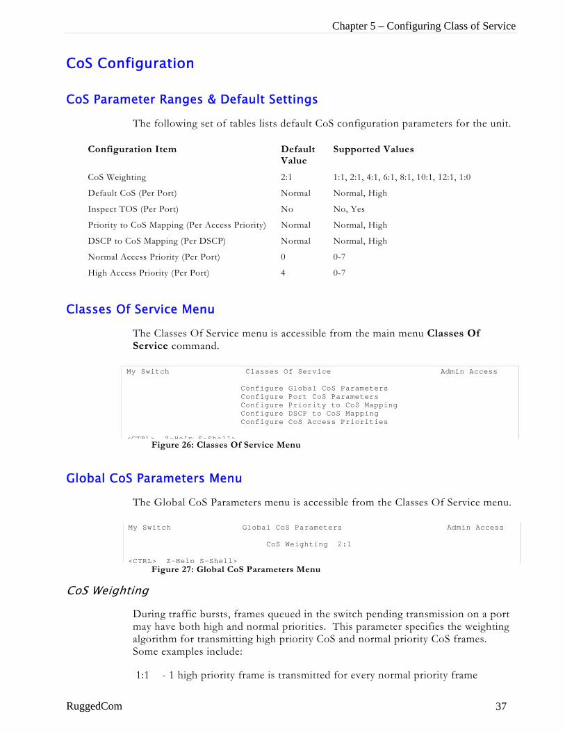
Chapter 5 – Configuring Class of Service
CoS Configuration
CoS Parameter Ranges & Default Settings
The following set of tables lists default CoS configuration parameters for the unit.
Configuration Item Default Value
Supported Values
CoS Weighting 2:1 1:1, 2:1, 4:1, 6:1, 8:1, 10:1, 12:1, 1:0
Default CoS (Per Port) Normal Normal, High
Inspect TOS (Per Port) No No, Yes
Priority to CoS Mapping (Per Access Priority) Normal Normal, High
DSCP to CoS Mapping (Per DSCP) Normal Normal, High
Normal Access Priority (Per Port) 0 0-7
High Access Priority (Per Port) 4 0-7
Classes Of Service Menu
The Classes Of Service menu is accessible from the main menu Classes Of Service command.
Global CoS
M <
CoS Weight
RuggedCom
Figure 26: Classes Of Service Menu
y Switch Classes Of Service Admin Access
Configure Global CoS Parameters Configure Port CoS Parameters Configure Priority to CoS Mapping Configure DSCP to CoS Mapping Configure CoS Access Priorities
CTRL> Z-Help S-Shell>
Parameters Menu
The Global CoS Parameters menu is accessible from the Classes Of Service menu.
M <
Figure 27: Global CoS Parameters Menu
y Switch Global CoS Parameters Admin Access
CoS Weighting 2:1
CTRL> Z-Help S-Shell>
ing
During traffic bursts, frames queued in the switch pending transmission on a port may have both high and normal priorities. This parameter specifies the weighting algorithm for transmitting high priority CoS and normal priority CoS frames. Some examples include:
1:1 - 1 high priority frame is transmitted for every normal priority frame
37
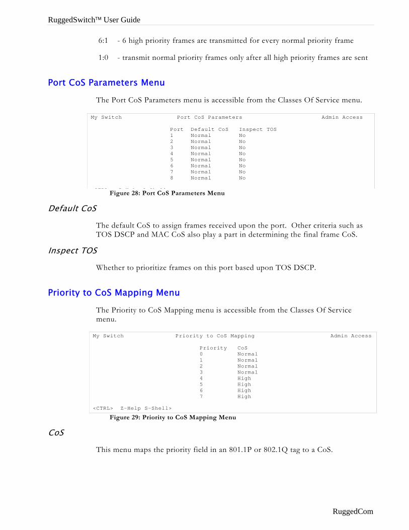
RuggedSwitch™ User Guide
6:1 - 6 high priority frames are transmitted for every normal priority frame
1:0 - transmit normal priority frames only after all high priority frames are sent
Port CoS Parameters Menu
The Port CoS Parameters menu is accessible from the Classes Of Service menu.
Figure 28: Port CoS Parameters Menu
Default CoS
The default CoS to assign frames received upon the port. Other criteria such as TOS DSCP and MAC CoS also play a part in determining the final frame CoS.
Inspect TOS
Whether to prioritize frames on this port based upon TOS DSCP.
Priority to CoS Mapping Menu
The Priority to CoS Mapping menu is accessible from the Classes Of Service menu.
Figure 29: Priority to CoS Mapping Menu
My Switch Port CoS Parameters Admin Access Port Default CoS Inspect TOS 1 Normal No 2 Normal No 3 Normal No 4 Normal No 5 Normal No 6 Normal No 7 Normal No 8 Normal No CTRL Z H l S Sh ll
My Switch Priority to CoS Mapping Admin Access Priority CoS 0 Normal 1 Normal 2 Normal 3 Normal 4 High 5 High 6 High 7 High <CTRL> Z-Help S-Shell>
CoS
This menu maps the priority field in an 801.1P or 802.1Q tag to a CoS.
RuggedCom
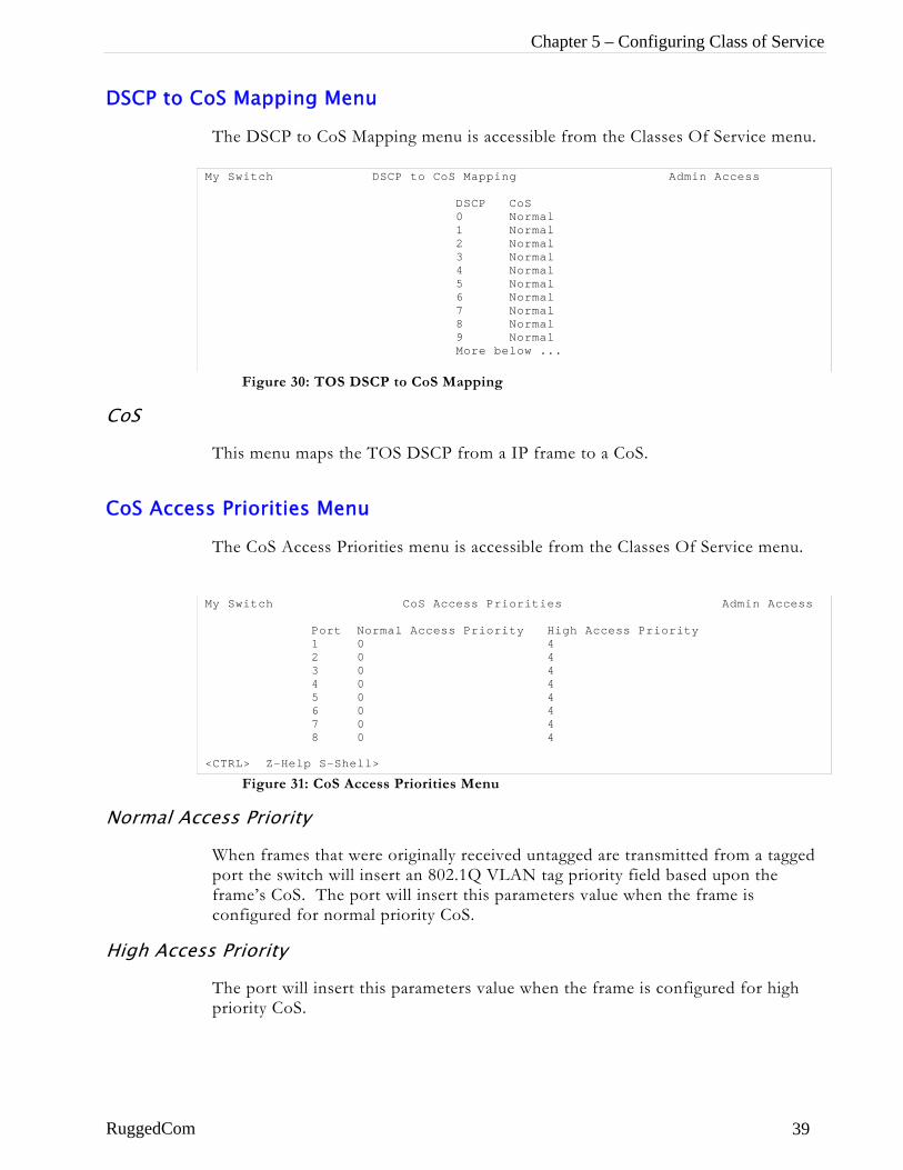
Chapter 5 – Configuring Class of Service
DSCP to CoS Mapping Menu
The DSCP to CoS Mapping menu is accessible from the Classes Of Service menu.
CoS
CoS Acces
M
M <
Normal Acc
High Acces
RuggedCom
Figure 30: TOS DSCP to CoS Mapping
y Switch DSCP to CoS Mapping Admin Access
DSCP CoS 0 Normal 1 Normal 2 Normal 3 Normal 4 Normal 5 Normal 6 Normal 7 Normal 8 Normal 9 Normal More below ...
This menu maps the TOS DSCP from a IP frame to a CoS.
s Priorities Menu
The CoS Access Priorities menu is accessible from the Classes Of Service menu.
Figure 31: CoS Access Priorities Menu
y Switch CoS Access Priorities Admin Access
Port Normal Access Priority High Access Priority 1 0 4 2 0 4 3 0 4 4 0 4 5 0 4 6 0 4 7 0 4 8 0 4
CTRL> Z-Help S-Shell>
ess Priority
When frames that were originally received untagged are transmitted from a tagged port the switch will insert an 802.1Q VLAN tag priority field based upon the frame’s CoS. The port will insert this parameters value when the frame is configured for normal priority CoS.
s Priority
The port will insert this parameters value when the frame is configured for high priority CoS.
39
RuggedSwitch™ User Guide
Chapter 6 – Configuring Rapid Spanning Tree
Introduction This chapter familiarizes the user with:
• RSTP Issues
• Planning RSTP networks
• Configuring RSTP
• Viewing the status and statistics of RSTP
• Troubleshooting RSTP
RSTP Features
RuggedSwitch™ RSTP provides you with the following features:
• Industry standard support of Rapid Spanning Tree (802.1w), which features a compatibility mode with legacy STP (802.1d).
• Superior performance. RuggedCom RSTP will recognize a link failure and put an alternate port into forwarding within milliseconds.
• Special support for ring architectures. RuggedCom RSTP features enhancements, which allow rapid recovery in rings.
• RSTP may be enabled on a per-port basis.
• Ports may be configured as edge ports, which allow rapid transitioning to the forwarding state for non-STP hosts.
• Path costs may be hard configured or determined by port speed negotiation, in either the STP or RSTP style.
• Full bridge1 and port status provide a rich set of tools for performance monitoring and debugging.
• SNMP manageable including newRoot and topologyChange traps.
1 Historically, a device implementing STP on its ports has been referred to as a bridge. RuggedCom uses the term bridge and switch synonymously.
RuggedCom
Chapter 6 – Configuring Rapid Spanning Tree
RSTP Concepts And Issues The 802.1d Spanning Tree Protocol was developed to allow the construction of robust networks that incorporate redundancy while pruning the active topology of the network to prevent loops. While STP is effective, it requires that frame transfer must halt after a link outage until all bridges in the network are sure to be aware of the new topology. Using the 802.1d recommended values, this period lasts 30 seconds.
Rapid Spanning Tree Protocol (IEEE 802.1w) is a further evolution of the 802.1d Spanning Tree Protocol. It replaces the settling period with an active handshake between bridges that guarantees topology information to be rapidly propagated through the network. RSTP also offers a number of other significant innovations, including:
• Topology changes in STP must be passed to the root bridge before they can be propagated to the network. Topology changes in RSTP can be originated from and acted upon by any designated bridges, leading to more rapid propagation of address information.
• STP recognizes one state, blocking, for ports that should not forward. RSTP explicitly recognizes two blocking roles, alternate and backup port roles, including them in computations of when to learn and forward.
• STP relays configuration messages received on the root port out its designated ports. If an STP bridge fails to receive a message from its neighbor it cannot be sure where along the path to the root a failure occurred. RSTP bridges generate their own configuration messages, even if they fail to receive one from the root bridge. This leads to quicker failure detection.
• RSTP offers edge port recognition, allowing ports at the edge of the network to forward frames immediately after activation while at the same time protecting them against loops.
• An improvement to age configuration messages more quickly to prevent them from “going around in circles” in the event of a loop.
RSTP Operation
RSTP States And Roles
RSTP Bridges have roles to play, being either root or designated. One bridge, the root bridge, is the practical center of the network. All other bridges in the network are designated bridges.
RSTP also assigns each port of the bridge a state and a role. The RSTP state describes what is happening at the port in relation to address learning and frame forwarding. The RSTP role basically describes whether the port is facing the center or edges of the network and whether it can currently be used or not.
State
RuggedCom 41

RuggedSwitch™ User Guide
There are three RSTP states: Discarding, Learning and Forwarding.
The discarding state is entered when the port is first taken into service. The port does not learn addresses in this state and does not participate in frame transfer. The port looks for STP traffic in order to determine its role in the network. When it is determined that the port will play an active part in the network, the state will change to Learning.
The learning state is entered when the port is preparing to play an active member of the network. The port learns addresses in this state but does not participate in frame transfer. In a network of RSTP bridges the time spent in this state is usually quite short. RSTP bridges operating in STP compatibility mode will spend 6 to 40 seconds in this state.
Afbo
NpuDilin
Figure 32: Bridge and Port States
ter “learning” the bridge will place the port in the forwarding state. The port th learns addresses and participates in frame transfer while in this state.
ote: RuggedSwitch™ introduces two more states, Disabled and Link Down. Introduced rely for purposes of management these states may be considered sub-classes of the RSTP scarding state. The Disabled state refers to links upon which RSTP has been disabled. The k down state refers to links upon which RSTP is enabled but are currently down.
Forwarding
Learning
Discarding
Disabled Link Down
Forwarding Timer ExpiresOr Active RSTP Handshake
Forwarding Timer ExpiresOr Active RSTP Handshake hasOccurred
Link rises or falls
RSTP Enabled
BPDUS indicateport should notbe active
RSTP Disabled in any state
RuggedCom
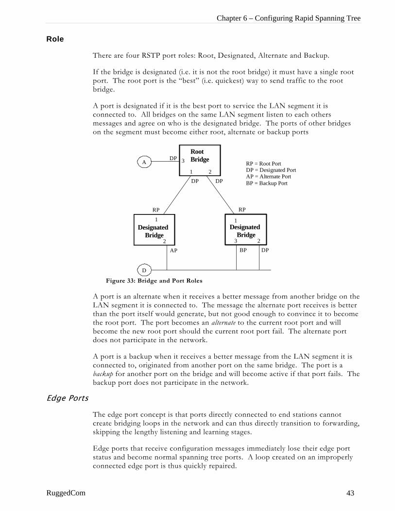
Chapter 6 – Configuring Rapid Spanning Tree
Role
There are four RSTP port roles: Root, Designated, Alternate and Backup.
If the bridge is designated (i.e. it is not the root bridge) it must have a single root port. The root port is the “best” (i.e. quickest) way to send traffic to the root bridge.
A port is designated if it is the best port to service the LAN segment it is connected to. All bridges on the same LAN segment listen to each others messages and agree on who is the designated bridge. The ports of other bridges on the segment must become either root, alternate or backup ports
Figure 33: Bridge and Port Roles
A port is an alternate when it receives a better message from another bridge on the LAN segment it is connected to. The message the alternate port receives is better than the port itself would generate, but not good enough to convince it to become the root port. The port becomes an alternate to the current root port and will become the new root port should the current root port fail. The alternate port does not participate in the network.
A port is a backup when it receives a better message from the LAN segment it is connected to, originated from another port on the same bridge. The port is a backup for another port on the bridge and will become active if that port fails. The backup port does not participate in the network.
D
Root Bridge
Designated Bridge
Designated Bridge
1 2
1
2
1
3 2
DP DP
RP RP
AP DPBP
A DP 3 RP = Root Port
DP = Designated Port AP = Alternate Port BP = Backup Port
Edge Ports
The edge port concept is that ports directly connected to end stations cannot create bridging loops in the network and can thus directly transition to forwarding, skipping the lengthy listening and learning stages.
Edge ports that receive configuration messages immediately lose their edge port status and become normal spanning tree ports. A loop created on an improperly connected edge port is thus quickly repaired.
RuggedCom 43
RuggedSwitch™ User Guide
Because an edge port services only end stations, topology change messages are not generated when its link toggles.
Point To Point and Multipoint Links
RSTP uses a peer-peer protocol called Proposing-Agreeing to ensure transitioning in the event of a link failure. This protocol is point to point and breaks down in multipoint situations, i.e. when more than two bridges operate on a shared media link.
If RSTP detects this circumstance (based upon the port’s half duplex state after link up) it will switch off Proposing-Agreeing. The port must transition through the learning and forwarding states spending the forward delay in each.
There are circumstances where RSTP will make an incorrect decision about the point-to-point state of the link simply by examining the half duplex status, namely:
• The port attaches only to a single partner, but through a half duplex link.
• The port attaches to a shared media hub through a full duplex link. The shared media link attaches to more than one RSTP enabled bridge.
In such cases the user may configure the bridge to override the half duplex determination mechanism and force the link to be treated in the proper fashion.
Path And Port Costs
The STP path cost is the main mechanism by which root and designated ports are chosen.2 The path cost for a designated bridge is the sum of the individual port costs on the links between the root bridge and that designated bridge. The port with the lowest path cost is the best route to the root bridge and is chosen as the root port.
How Port Costs Are Generated
Port costs can be generated either as a result of link autonegotiation or manual configuration.
When the link autonegotiation method is used the port cost is derived from the speed of the link. This method is useful when a well-connected network has been established. It can be used when the designer is not too concerned with the resultant topology as long as connectivity is assured.
Manual configuration is useful when the exact topology of the network must be predictable under all circumstances. The path cost can be used to establish the topology of the network exactly as the designer intends.
2 In actuality the primary determinant for root port selection is the root bridge ID. Bridge ID is important mainly at the network startup when the bridge with the lowest id is elected as the root bridge. After startup (when all bridges agree on the root bridge’s id) the path cost is used to select root ports. If the path costs of candidates for the root port are the same, the ID of the peer bridge is used to select the port. Finally, if candidate root ports have the same path cost and peer bridge ID, the port ID of the peer bridge is used to select the root port. In all cases the lower ID, path cost or port ID is selected as the best.
RuggedCom
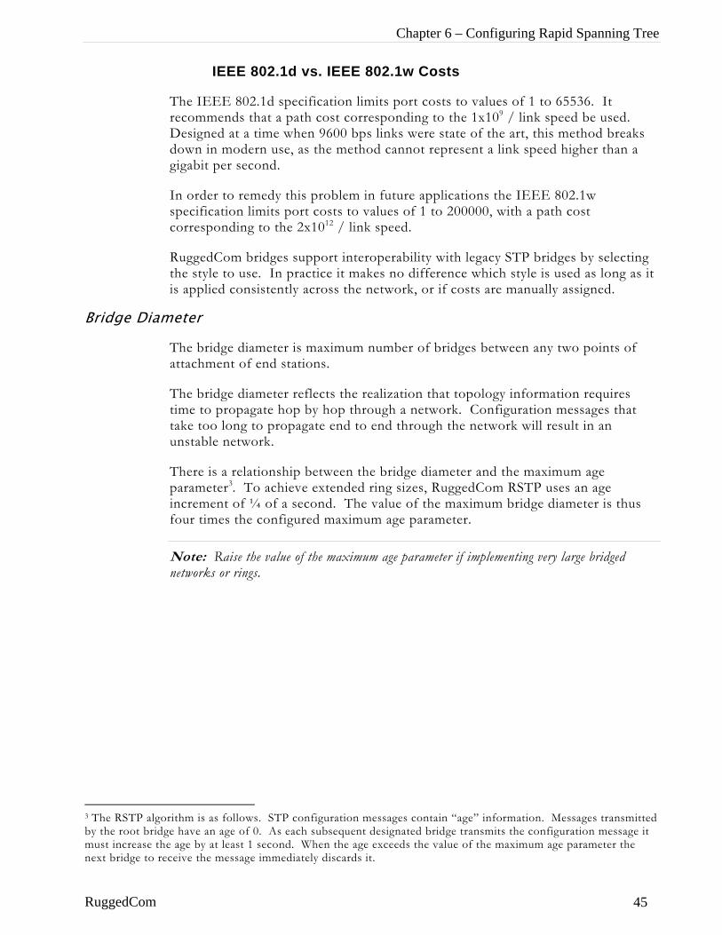
Chapter 6 – Configuring Rapid Spanning Tree
IEEE 802.1d vs. IEEE 802.1w Costs
The IEEE 802.1d specification limits port costs to values of 1 to 65536. It recommends that a path cost corresponding to the 1x10⁹ / link speed be used. Designed at a time when 9600 bps links were state of the art, this method breaks down in modern use, as the method cannot represent a link speed higher than a gigabit per second.
In order to remedy this problem in future applications the IEEE 802.1w specification limits port costs to values of 1 to 200000, with a path cost corresponding to the 2x10¹² / link speed.
RuggedCom bridges support interoperability with legacy STP bridges by selecting the style to use. In practice it makes no difference which style is used as long as it is applied consistently across the network, or if costs are manually assigned.
Bridge Diameter
The bridge diameter is maximum number of bridges between any two points of attachment of end stations.
The bridge diameter reflects the realization that topology information requires time to propagate hop by hop through a network. Configuration messages that take too long to propagate end to end through the network will result in an unstable network.
There is a relationship between the bridge diameter and the maximum age parameter3. To achieve extended ring sizes, RuggedCom RSTP uses an age increment of ¼ of a second. The value of the maximum bridge diameter is thus four times the configured maximum age parameter.
Note: Raise the value of the maximum age parameter if implementing very large bridged networks or rings.
3 The RSTP algorithm is as follows. STP configuration messages contain “age” information. Messages transmitted by the root bridge have an age of 0. As each subsequent designated bridge transmits the configuration message it must increase the age by at least 1 second. When the age exceeds the value of the maximum age parameter the next bridge to receive the message immediately discards it.
RuggedCom 45
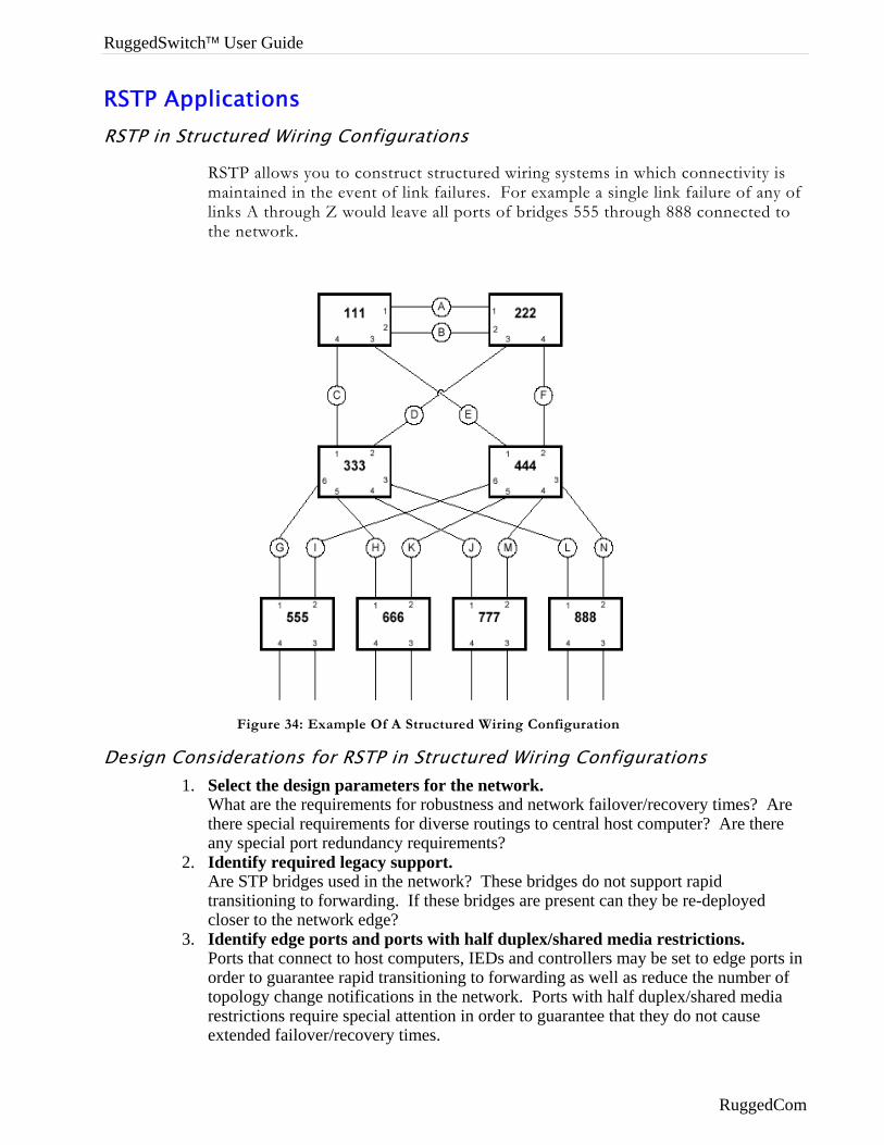
RuggedSwitch™ User Guide
RSTP Applications RSTP in Structured Wiring Configurations
RSTP allows you to construct structured wiring systems in which connectivity is maintained in the event of link failures. For example a single link failure of any of links A through Z would leave all ports of bridges 555 through 888 connected to the network.
Figure 34: Example Of A Structured Wiring Configuration
Design Considerations for RSTP in Structured Wiring Configurations 1. Select the design parameters for the network.
What are the requirements for robustness and network failover/recovery times? Are there special requirements for diverse routings to central host computer? Are there any special port redundancy requirements?
2. Identify required legacy support. Are STP bridges used in the network? These bridges do not support rapid transitioning to forwarding. If these bridges are present can they be re-deployed closer to the network edge?
3. Identify edge ports and ports with half duplex/shared media restrictions. Ports that connect to host computers, IEDs and controllers may be set to edge ports in order to guarantee rapid transitioning to forwarding as well as reduce the number of topology change notifications in the network. Ports with half duplex/shared media restrictions require special attention in order to guarantee that they do not cause extended failover/recovery times.
RuggedCom
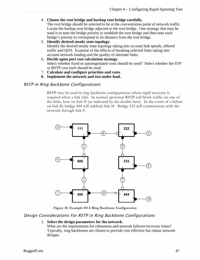
Chapter 6 – Configuring Rapid Spanning Tree
4. Choose the root bridge and backup root bridge carefully. The root bridge should be selected to be at the concentration point of network traffic. Locate the backup root bridge adjacent to the root bridge. One strategy that may be used is to tune the bridge priority to establish the root bridge and then tune each bridge’s priority to correspond to its distance from the root bridge.
5. Identify desired steady state topology. Identify the desired steady state topology taking into account link speeds, offered traffic and QOS. Examine of the effects of breaking selected links taking into account network loading and the quality of alternate links.
6. Decide upon port cost calculation strategy. Select whether fixed or autonegotiated costs should be used? Select whether the STP or RSTP cost style should be used.
7. Calculate and configure priorities and costs. 8. Implement the network and test under load.
RSTP in Ring Backbone Configurations
RSTP may be used in ring backbone configurations where rapid recovery is required when a link fails. In normal operation RSTP will block traffic on one of the links, here on link H (as indicated by the double bars). In the event of a failure on link D, bridge 444 will unblock link H. Bridge 333 will communicate with the network through link F.
Design Conside1. Sele
WhaTypdesi
RuggedCom
Figure 35: Example Of A Ring Backbone Configuration
rations For RSTP in Ring Backbone Configurations ct the design parameters for the network. t are the requirements for robustness and network failover/recovery times?
ically, ring backbones are chosen to provide cost effective but robust network gns.
47
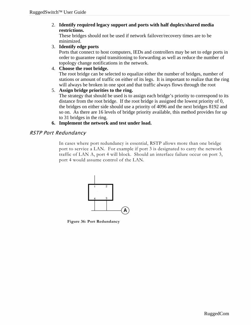
RuggedSwitch™ User Guide
2. Identify required legacy support and ports with half duplex/shared media restrictions. These bridges should not be used if network failover/recovery times are to be minimized.
3. Identify edge ports Ports that connect to host computers, IEDs and controllers may be set to edge ports in order to guarantee rapid transitioning to forwarding as well as reduce the number of topology change notifications in the network.
4. Choose the root bridge. The root bridge can be selected to equalize either the number of bridges, number of stations or amount of traffic on either of its legs. It is important to realize that the ring will always be broken in one spot and that traffic always flows through the root
5. Assign bridge priorities to the ring. The strategy that should be used is to assign each bridge’s priority to correspond to its distance from the root bridge. If the root bridge is assigned the lowest priority of 0, the bridges on either side should use a priority of 4096 and the next bridges 8192 and so on. As there are 16 levels of bridge priority available, this method provides for up to 31 bridges in the ring.
6. Implement the network and test under load.
RSTP Port Redundancy
In cases where port redundancy is essential, RSTP allows more than one bridge port to service a LAN. For example if port 3 is designated to carry the network traffic of LAN A, port 4 will block. Should an interface failure occur on port 3, port 4 would assume control of the LAN.
Figure 36: Port Redundancy
RuggedCom
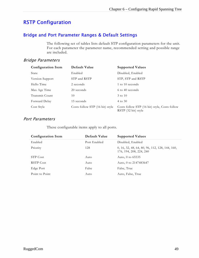
Chapter 6 – Configuring Rapid Spanning Tree
RSTP Configuration
Bridge and Port Parameter Ranges & Default Settings
The following set of tables lists default STP configuration parameters for the unit. For each parameter the parameter name, recommended setting and possible range are included.
Bridge Parameters Configuration Item Default Value Supported Values
State Enabled Disabled, Enabled
Version Support STP and RSTP STP, STP and RSTP
Hello Time 2 seconds 1 to 10 seconds
Max Age Time 20 seconds 6 to 40 seconds
Transmit Count 10 3 to 10
Forward Delay 15 seconds 4 to 30
Cost Style Costs follow STP (16 bit) style Costs follow STP (16 bit) style, Costs follow RSTP (32 bit) style
Port Parameters
These configurable items apply to all ports.
Configuration Item Default Value Supported Values
Enabled Port Enabled Disabled, Enabled
Priority 128 0, 16, 32, 48, 64, 80, 96, 112, 128, 144, 160, 176, 194, 208, 224, 240
STP Cost Auto Auto, 0 to 65535
RSTP Cost Auto Auto, 0 to 2147483647
Edge Port False False, True
Point to Point Auto Auto, False, True
RuggedCom 49
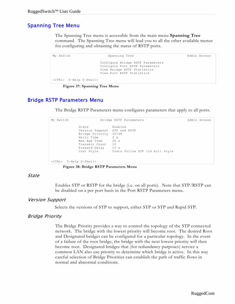
RuggedSwitch™ User Guide
Spanning Tree Menu
The Spanning Tree menu is accessible from the main menu Spanning Tree command. The Spanning Tree menu will lead you to all the other available menus for configuring and obtaining the status of RSTP ports.
Figure 37: Spanning Tree Menu
Bridge RSTP Parameters Menu
The Bridge RSTP Parameters menu configures parameters that apply to all ports.
Figure 38: Bridge RSTP Parameters Menu
My Switch Spanning Tree Admin Access Configure Bridge RSTP Parameters Configure Port RSTP Parameters View Bridge RSTP Statistics View Port RSTP Statistics <CTRL> Z-Help S-Shell>
My Switch Bridge RSTP Parameters Admin Access State Enabled Version Support STP and RSTP Bridge Priority 32768 Hello Time 2 s Max Age Time 20 s Transmit Count 10 Forward Delay 15 s Cost Style Costs follow STP (16 bit) style <CTRL> Z-Help S-Shell>
State
Enables STP or RSTP for the bridge (i.e. on all ports). Note that STP/RSTP can be disabled on a per port basis in the Port RSTP Parameters menu.
Version Support Selects the versions of STP to support, either STP or STP and Rapid STP.
Bridge Priority
The Bridge Priority provides a way to control the topology of the STP connected network. The bridge with the lowest priority will become root. The desired Root and Designated bridges can be configured for a particular topology. In the event of a failure of the root bridge, the bridge with the next lowest priority will then become root. Designated bridges that (for redundancy purposes) service a common LAN also use priority to determine which bridge is active. In this way careful selection of Bridge Priorities can establish the path of traffic flows in normal and abnormal conditions.
RuggedCom
Chapter 6 – Configuring Rapid Spanning Tree
Hello Time
This is the time between configuration messages issued by the root bridge. Shorter hello times may result in faster detection of topology changes at the expense of moderate increases in STP traffic.
Max Age Time
The time a configuration message remains valid after being issued by the root bridge. Configure this parameter with care when many tiers of bridges exist, or slow speed links (such as those used in WANs) are part of the network
Transmit Count
The maximum number of configuration messages on each port that may be sent in a special event (such as recovering from a failure or bringing up a new link). After the maximum number of messages is reached, STP will be limited to 1 message per second. Larger values allow the network to recover from failed links more quickly. If RSTP is being used in a ring architecture the transmit count should be larger than the number of switches in the ring. Specifying a large value for the transmit count renders RSTP recovery more robust in the presence of multiple link failures that occur in a short window of time.
Forward Delay
The amount of time the bridge spends learning MAC addresses on a rising port before beginning to forward traffic. Lower values allow the port to reach the forwarding state more quickly, but at the expense of flooding unlearned addresses to all ports.
Cost Style
This parameter selects the style of link costs to employ. STP uses 16-bit path costs based upon 1x10E9/link speed (19 for 100 Mbps and 100 for 10 Mbps) whereas RSTP uses 32 bit costs based upon 2x10E13/link speed (200,000 for 100 Mbps and 2,000,000 for 10 Mbps). Note that RSTP link costs are used only when the bridge version support is set to allow RSTP and the port does not migrate to STP.
RuggedCom 51
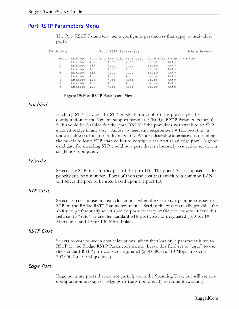
RuggedSwitch™ User Guide
Port RSTP Parameters Menu
The Port RSTP Parameters menu configures parameters that apply to individual ports.
Enabled
Priority
STP Cost
RSTP Cos
Edge Por
Figure 39: Port RSTP Parameters Menu
My Switch Port RSTP Parameters Admin Access Port Enabled Priority STP Cost RSTP Cost Edge Port Point to Point 1 Enabled 128 Auto Auto False Auto 2 Enabled 128 Auto Auto False Auto 3 Enabled 128 Auto Auto False Auto 4 Enabled 128 Auto Auto False Auto 5 Enabled 128 Auto Auto False Auto 6 Enabled 128 Auto Auto False Auto 7 Enabled 128 Auto Auto False Auto 8 Enabled 128 Auto Auto False Auto CTRL Z H l S Sh ll
Enabling STP activates the STP or RSTP protocol for this port as per the configuration of the Version support parameter (Bridge RSTP Parameters menu). STP should be disabled for the port ONLY if the port does not attach to an STP enabled bridge in any way. Failure to meet this requirement WILL result in an undetectable traffic loop in the network. A more desirable alternative is disabling the port is to leave STP enabled but to configure the port as an edge port. A good candidate for disabling STP would be a port that is absolutely assured to services a single host computer.
Selects the STP port priority part of the port ID. The port ID is composed of the priority and port number. Ports of the same cost that attach to a common LAN will select the port to be used based upon the port ID.
Selects to cost to use in cost calculations, when the Cost Style parameter is set to STP on the Bridge RSTP Parameters menu. Setting the cost manually provides the ability to preferentially select specific ports to carry traffic over others. Leave this field set to "auto" to use the standard STP port costs as negotiated (100 for 10 Mbps links and 19 for 100 Mbps links).
t
Selects to cost to use in cost calculations, when the Cost Style parameter is set to RSTP on the Bridge RSTP Parameters menu. Leave this field set to "auto" to use the standard RSTP port costs as negotiated (2,000,000 for 10 Mbps links and 200,000 for 100 Mbps links).
t
Edge ports are ports that do not participate in the Spanning Tree, but still are sent configuration messages. Edge ports transition directly to frame forwarding
RuggedCom
Chapter 6 – Configuring Rapid Spanning Tree
without any listening and learning delays. The MAC tables of Edge ports do not need to be flushed when topology changes occur in the STP network.
Unlike an STP disabled port, accidentally connecting an edge port to another port in the spanning tree will result in a detectable loop. The "edgeness" of the port will be switched off and the standard RSTP rules will apply (until the next link outage).
Point To Point
RSTP uses a peer-to-peer protocol that provides for rapid transitioning on point-to-point links. This protocol is automatically turned off in situations where multiple STP bridges communicate over a shared (non point to point) LAN.
The bridge will automatically take point to point to be true when the link is found to be operating full duplex. The point-to-point parameter allows this behaviour or overrides it, forcing point to point to be true or false. Force the parameter true when the port operates a point-to-point link but cannot run the link full duplex. Force the parameter false when the port operates the link full duplex, but is still not point to point (e.g. a full duplex link to an unmanaged bridge that concentrates two other STP bridges).
RuggedCom 53
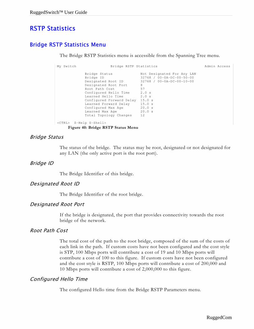
RuggedSwitch™ User Guide
RSTP Statistics
Bridge RSTP Statistics Menu
The Bridge RSTP Statistics menu is accessible from the Spanning Tree menu.
Bridge Stat
Bridge ID
Designated
Designated
Root Path C
Configured
Figure 40: Bridge RSTP Status Menu
My Switch Bridge RSTP Statistics Admin Access Bridge Status Not Designated For Any LAN Bridge ID 32768 / 00-0A-DC-00-50-00 Designated Root ID 32768 / 00-0A-DC-00-10-00 Designated Root Port 8 Root Path Cost 57 Configured Hello Time 2.0 s Learned Hello Time 2.0 s Configured Forward Delay 15.0 s Learned Forward Delay 15.0 s Configured Max Age 20.0 s Learned Max Age 20.0 s Total Topology Changes 12 <CTRL> Z-Help S-Shell>
us
The status of the bridge. The status may be root, designated or not designated for any LAN (the only active port is the root port).
The Bridge Identifier of this bridge.
Root ID
The Bridge Identifier of the root bridge.
Root Port
If the bridge is designated, the port that provides connectivity towards the root bridge of the network.
ost
The total cost of the path to the root bridge, composed of the sum of the costs of each link in the path. If custom costs have not been configured and the cost style is STP, 100 Mbps ports will contribute a cost of 19 and 10 Mbps ports will contribute a cost of 100 to this figure. If custom costs have not been configured and the cost style is RSTP, 100 Mbps ports will contribute a cost of 200,000 and 10 Mbps ports will contribute a cost of 2,000,000 to this figure.
Hello Time
The configured Hello time from the Bridge RSTP Parameters menu.
RuggedCom

Chapter 6 – Configuring Rapid Spanning Tree
Learned Hello Time
The actual Hello time provided by the root bridge as learned in configuration messages. This time is used in designated bridges.
Configured Forward Delay
The configured Forward Delay time from the Bridge RSTP Parameters menu.
Learned Forward Delay
The actual Forward Delay time provided by the root bridge as learned in configuration messages. This time is used in designated bridges.
Configured Max Age
The configured Maximum Age time from the Bridge RSTP Parameters menu.
Learned Max Age
The actual Maximum Age time provided by the root bridge as learned in configuration messages. This time is used in designated bridges.
Total Topology Changes
A count of topology changes in the network, as detected on this bridge through link failures or as signaled from other bridges. Excessively high or rapidly increasing counts signal network problems.
RuggedCom 55
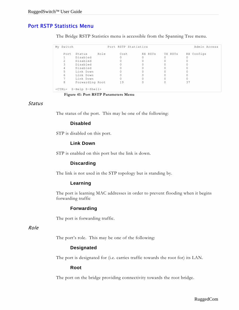
RuggedSwitch™ User Guide
Port RSTP Statistics Menu
The Bridge RSTP Statistics menu is accessible from the Spanning Tree menu.
Figure 41: Port RSTP Parameters Menu
My Switch Port RSTP Statistics Admin Access Port Status Role Cost RX RSTs TX RSTs RX Configs 1 Disabled 0 0 0 0 2 Disabled 0 0 0 0 3 Disabled 0 0 0 0 4 Disabled 0 0 0 0 5 Link Down 0 0 0 0 6 Link Down 0 0 0 0 7 Link Down 0 0 0 0 8 Forwarding Root 19 0 0 37 <CTRL> Z-Help S-Shell>
Status
The status of the port. This may be one of the following:
Disabled
STP is disabled on this port.
Link Down
STP is enabled on this port but the link is down.
Discarding
The link is not used in the STP topology but is standing by.
Learning
The port is learning MAC addresses in order to prevent flooding when it begins forwarding traffic
Forwarding
The port is forwarding traffic.
Role
The port’s role. This may be one of the following:
Designated
The port is designated for (i.e. carries traffic towards the root for) its LAN.
Root
The port on the bridge providing connectivity towards the root bridge.
RuggedCom
Chapter 6 – Configuring Rapid Spanning Tree
Backup
The port is attached to a LAN that is serviced by another port on the bridge. It is not used but is standing by. If a failure of the port that is currently designated for the LAN occurs the backup port will become designated for the LAN.
Alternate
The port is attached to a bridge that provides connectivity to the root bridge. It is not used but is standing by. If a failure of the current root port occurs this port will become the new root. If there are multiple alternate ports the best candidate (cost wise) will be elected root.
Cost
The cost of this port. If the Bridge RSTP Parameters Cost Style is set to STP, 100 Mbps ports will contribute a cost of 19 and 10 Mbps ports contribute a cost of 100. If the Cost Style is set to RSTP, 100 Mbps ports will contribute a cost of 200,000 and 10 Mbps ports contribute a cost of 2,000,000. Note that even if the Cost style is set to RSTP, a port that migrates to STP will have its cost limited to a maximum of 65535.
RX RSTs
The count of RSTP configuration messages received on this port.
TX RSTs
The count of RSTP configuration messages transmitted on this port.
RX Configs
The count of STP configuration messages received on this port.
TX Configs
The count of STP configuration messages transmitted on this port.
RX Tcns
The count of configuration change notification messages received on this port. Excessively high or rapidly increasing counts signal network problems.
TX Tcns
The count of configuration messages transmitted on this port.
Designated Root ID
Provided on the root ports of designated bridges, the Bridge Identifier of the bridge this port is connected to.
RuggedCom 57
RuggedSwitch™ User Guide
Troubleshooting Problem One
• When I connect up a new port the network locks up solid. The port status LEDs are flashing madly.
• Occasionally, the network seems to experience a lot of flooding. All the ports seem to experience significant traffic. The problem lasts a few seconds and then goes away.
• One of my switches displays a strange behaviour where the root port hops back and forth between two switch ports and never settles down.
Is it possible that one of the switches in the network or one of the ports on a switch in the network have STP disabled and accidentally connects to another switch? If this has occurred then a traffic loop has been formed.
If the problem appears to be transient in nature, it is possible that ports that are part of the spanning tree have been configured as edge ports. After the link layers have risen on edge ports, STP will directly transition them (perhaps improperly) to the forwarding state. If an RSTP configuration message is then received the port will be returned to blocking. A traffic loop may be formed for the length of time the port was in forwarding.
If one of the switches appears to flap the root from one port to another the problem may be one of traffic prioritization (See problem five).
Another possible cause of intermittent operation is that of an autonegotiation mismatch. If one end of the link is fixed to full duplex and the peer autonegotiates, the autonegotiating end will fallback to half-duplex operation. At lower traffic the volumes the link may display few if any errors. As the traffic volume rises the fixed negotiation side will begin to experience dropped packets while the autonegotiating side will experience collisions. Ultimately, as traffic loads approach 100% the link will become entirely unusable. At this point RSTP will not be able to transmit configuration messages over the link and the spanning tree topology will breakdown. If an alternate trunk exists RSTP will activate it in the place of the congested port. Since activation of the alternate port often relieves the congested port of its traffic, the congested port will once again become reliable. RSTP will promptly enter it back into service, beginning the cycle once again. The root port will flap back and forth between two ports on the switch.
Problem Two • My PC/IED/Device is on your switch. After I reset the switch, it
takes a long time before it comes up.
Is it possible that the RSTP edge setting for this port is set to false? If edge is set false the bridge will make the port go through two forward delay times before the port can send or receive frames. If edge is set true the bridge will transition the port directly to forwarding upon link up.
RuggedCom
Chapter 6 – Configuring Rapid Spanning Tree
Another possible explanation is that some links in the network run half duplex. RSTP uses a peer-peer protocol called Proposing-Agreeing to ensure transitioning in the event of a link failure. This protocol requires full duplex operation. When RSTP detects a non-half duplex port it cannot use the Proposing-Agreeing protocol and must make the port transition the slow (i.e. STP) way. If possible configure the port for full duplex operation otherwise configure the port’s Point to Point setting to true. Either will allow the Proposing-Agreeing protocol to be used.
Problem Three • When I test your switch by deliberately breaking a link, it takes a
long time before I can poll devices past the switch. I thought RSTP was supposed to be fast. What is happening?
Is it possible that ports participating in the topology have been configured to STP mode or that the port’s Point to Point parameter is set false? STP and multipoint ports converge slowly after failures occur.
Is it possible that the port has migrated to STP? If the port is connected to the LAN segment by shared media and STP bridges are connected to that media then convergence after link failure will be slow.
Delays on the order of tens or hundreds of milliseconds can result in circumstances where the link broken is the sole link to the root bridge and the secondary root bridge is poorly chosen. The worst of all possible designs occurs when the secondary root bridge is located at the farthest edge of the network from the root. In this case a configuration message will have to propagate out to the edge and then back in order to reestablish the topology.
Problem Four • My network is composed of ring of bridges of which two
(connected to each other) are managed and the rest of unmanaged. Why does the RSTP protocol work quickly when I break a link between the managed bridges but not in the unmanaged bridge part of the ring?
A properly operating unmanaged bridge is transparent to configuration messages. The managed bridges will exchange configuration messages through the unmanaged bridge part of the ring as if it is non-existent. When a link in the unmanaged part of the ring fails however, the managed bridges will only be able to detect the failure through timing out of hello messages. Full connectivity will require three hello times plus two forwarding times to be restored.
Problem Five • The switch is up and running and working fine. Then I start a
certain application and the network becomes unstable. After I stop the application the network goes back to running normally.
RSTP sends its configuration messages using the highest possible priority level. If QOS is configured to allow traffic flows at the high priority level and these traffic
RuggedCom 59
RuggedSwitch™ User Guide
flows burst continuously to 100% of the line bandwidth, STP can be disrupted. Restrict the traffic flows to below 100%.
Problem Six • After I bring up a new port the root moves on to that port, and I
don’t want it to.
• The port that I want to become root won’t do so.
Is it possible that the port cost is incorrectly programmed or that autonegotiation derives an undesired value? Inspect the port and path costs with each port active as root.
Problem Seven • My IED/Controller doesn’t work with your switch.
Certain low CPU bandwidth controllers have been found to behave less than perfectly when they receive unexpected traffic. Try disabling STP for the port.
If the controller fails around the time of a link outage then there is the remote possibility that frame misordering or duplication may be the cause of the problem. Try setting the root port of the failing controllers bridge to STP.
Problem Eight • My network runs fine with your switch but I occasionally lose
polls to my devices.
Inspect network statistics to determine if the root bridge is receiving TCNs around the time of frame loss. It may be possible that you have problems with intermittent links in your network.
Problem Nine • I’m getting lots of TCNs at the root, where are they coming from?
Examine the RSTP port statistics to determine the port from which the TCNs are arriving. Sign-on to the switch at the other end of the link attached to that port. Repeat this step until the switch generating the TCNs is found (i.e. the switch that is itself not receiving a large number of TCNs). Determine the problem at that switch.
RuggedCom
Chapter 7 – Configuring Multicast Filtering
Chapter 7 – Configuring MULTICAST FILTERING
Introduction to Multicast Filtering
RuggedSwitch™ accomplishes multicast Filtering through the use of the Internet Group Management Protocol (IGMP) snooping.
IGMP is used by IP hosts to report their host group memberships to multicast routers. As hosts join and leave specific multicast groups, streams of traffic are directed to or withheld from that host.
The IGMP protocol operates between multicast routers and IP hosts. When an unmanaged switch is placed between multicast routers and their hosts, the multicast streams will be distributed to all ports. This may introduce significant traffic onto ports that do not require it and receive no benefit from it.
RuggedCom switches with IGMP Snooping enabled will act upon IGMP messages sent from the router and the host, restricting traffic streams to the appropriate LAN segments.
This chapter familiarizes the user with:
• IGMP Terminology and Issues
• Configuring IGMP Snooping
• Viewing IGMP Snooping status and statistics
• Troubleshooting IGMP Snooping
IGMP Features
RuggedCom IGMP provides you with the following features:
• Industry standard support of IGMP (RFC 1112, RFC 2236) versions 1 and 2 in active and passive roles.
Note: RuggedSwitch™ IGMP Snooping supports multicast routers using IGMP version 2 and hosts using either IGMP version 1 and 2.
• IGMP may be enabled on a per VLAN basis.
• Multicast Routers may be statically configured or dynamically recognized.
• “Routerless” operation.
• Support of up to 256 multicast groups.
RuggedCom 61
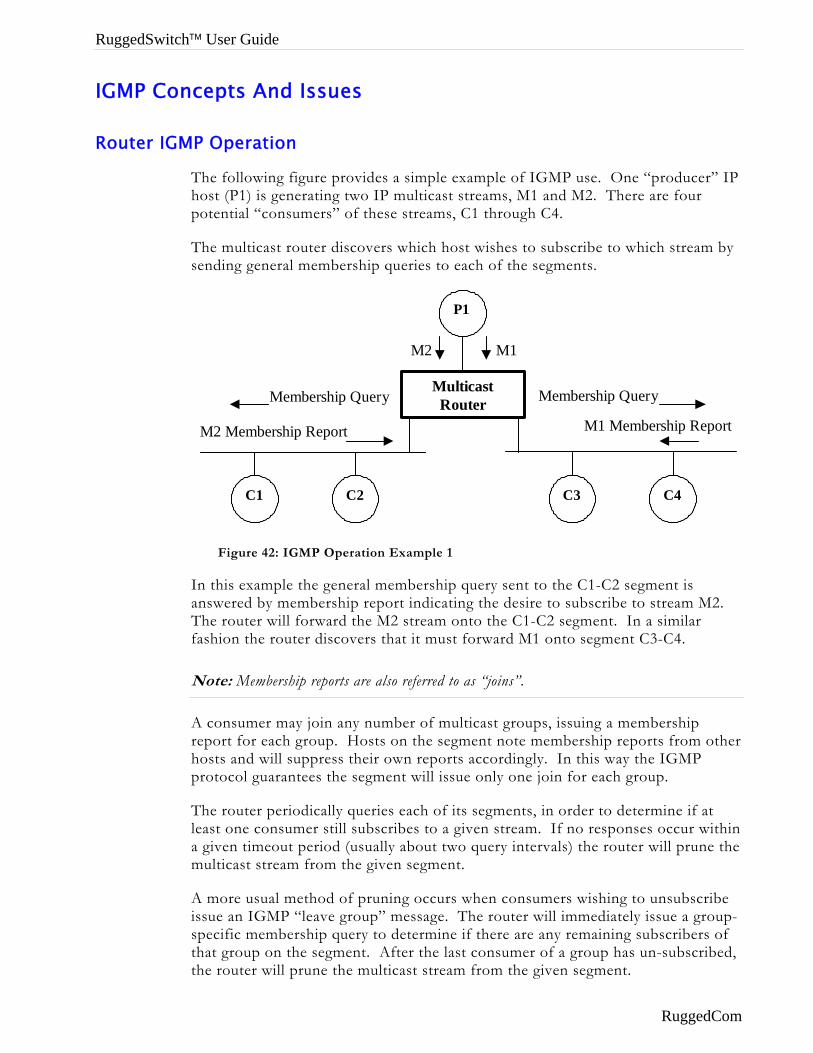
RuggedSwitch™ User Guide
IGMP Concepts And Issues
Router IGMP Operation
The following figure provides a simple example of IGMP use. One “producer” IP host (P1) is generating two IP multicast streams, M1 and M2. There are four potential “consumers” of these streams, C1 through C4.
The multicast router discovers which host wishes to subscribe to which stream by sending general membership queries to each of the segments.
Multicast Router
P1
C1 C2 C3 C4
M1 M2
Membership Query
M1 Membership Report
Membership Query
M2 Membership Report
Figure 42: IGMP Operation Example 1
In this example the general membership query sent to the C1-C2 segment is answered by membership report indicating the desire to subscribe to stream M2. The router will forward the M2 stream onto the C1-C2 segment. In a similar fashion the router discovers that it must forward M1 onto segment C3-C4.
Note: Membership reports are also referred to as “joins”.
A consumer may join any number of multicast groups, issuing a membership report for each group. Hosts on the segment note membership reports from other hosts and will suppress their own reports accordingly. In this way the IGMP protocol guarantees the segment will issue only one join for each group.
The router periodically queries each of its segments, in order to determine if at least one consumer still subscribes to a given stream. If no responses occur within a given timeout period (usually about two query intervals) the router will prune the multicast stream from the given segment.
A more usual method of pruning occurs when consumers wishing to unsubscribe issue an IGMP “leave group” message. The router will immediately issue a group-specific membership query to determine if there are any remaining subscribers of that group on the segment. After the last consumer of a group has un-subscribed, the router will prune the multicast stream from the given segment.
RuggedCom
Chapter 7 – Configuring Multicast Filtering
Switch IGMP Active and Passive Operation
The IGMP Snooping protocol provides a means for switches to snoop (i.e. watch) the operation of routers, respond with joins/leaves on the behalf of consumer ports and to prune multicast streams accordingly.
There are two modes of IGMP the switch can be configured to assume, active and passive.
Active Mode
When such a switch is used without a multicast router, it is able to function as if it is a multicast router. The switch acts as a multicast router, sending general/specific queries, processing leaves/joins and actively pruning the network.
When such a switch is used in a network with a multicast router, it is able to assist the multicast router. The switch relies upon the router to issue general queries, which it relays to consumers. The switch assists the router by issuing its own specific queries, responding to the router with leaves/joins and actively pruning the network.
Passive Mode
Some routers have problems with switches running IGMP and will mistakenly recognize them as routers. To enable operation with such broken and older routers, the RuggedSwitch™ can be configured to run Passive IGMP. This mode prevents the switch from sending the queries that can confuse the router, but at the cost of slower pruning.
Note: Active mode IGMP is much to be preferred to passive mode. In active mode the switch can issue specific queries to determine when the last member has left a multicast group. This leads to rapid pruning. Passive mode switches are not allowed to send queries of any kind. They must age out information gathered by router queries, which leads to much slower pruning.
Note: A switch running in passive mode requires the presence of a multicast router or it will not be able to forward multicast streams at all!
RuggedCom 63
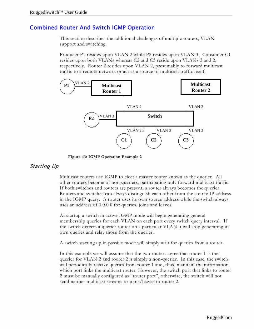
RuggedSwitch™ User Guide
Combined Router And Switch IGMP Operation
This section describes the additional challenges of multiple routers, VLAN support and switching.
Producer P1 resides upon VLAN 2 while P2 resides upon VLAN 3. Consumer C1 resides upon both VLANs whereas C2 and C3 reside upon VLANs 3 and 2, respectively. Router 2 resides upon VLAN 2, presumably to forward multicast traffic to a remote network or act as a source of multicast traffic itself.
Multicast Router 1
P1
C1 C2 C3
Switch
Multicast Router 2
VLAN 2,3 VLAN 3 VLAN 2
VLAN 2
VLAN 2
P2 VLAN 3
VLAN 2
Figure 43: IGMP Operation Example 2
Starting Up
Multicast routers use IGMP to elect a master router known as the querier. All other routers become of non-queriers, participating only forward multicast traffic. If both switches and routers are present, a router always becomes the querier. Routers and switches can always distinguish each other from the source IP address in the IGMP query. A router uses its own source address while the switch always uses an address of 0.0.0.0 for queries, joins and leaves.
At startup a switch in active IGMP mode will begin generating general membership queries for each VLAN on each port every switch query interval. If the switch detects a querier router on a particular VLAN it will stop generating its own queries and relay those from the querier.
A switch starting up in passive mode will simply wait for queries from a router.
In this example we will assume that the two routers agree that router 1 is the querier for VLAN 2 and router 2 is simply a non-querier. In this case, the switch will periodically receive queries from router 1 and, thus, maintain the information which port links the multicast router. However, the switch port that links to router 2 must be manually configured as “router port”, otherwise, the switch will not send neither multicast streams or joins/leaves to router 2.
RuggedCom
Chapter 7 – Configuring Multicast Filtering
Note that VLAN 3 does not have an external multicast router. The switch will operating in its “routerless” mode and issue general membership queries as if it is the router.
Processing Joins
If host C1 desires to subscribe to the multicast streams for both P1 and P2, it will generate two joins. The join from C1 on VLAN 2 will cause the switch to immediately initiate its own join to multicast router 1 (and to issue its own join as a response to queries).
The join from C1 for VLAN 3 will cause the switch to immediately begin forwarding multicast traffic from P2 to C2.
Processing Leaves
When host C1 decides to leave a multicast group it will issue a leave request to the switch. If the switch is in active mode it will specific poll the port to determine if C1 is the last member of the group on that port. If C1 is the last (or only) member, the switch will issue a leave to the router and the group will immediately be pruned from the port.
If the switch is configured to run in passive mode, it will age out the membership of C1 in the group before pruning.
Should host C1 leave the multicast group without issuing a leave group message and then fail to respond to a general membership query, the switch will stop forwarding traffic after two queries.
Multicast Sources
When a multicast source starts multicasting, the traffic stream will be immediately blocked on segments from which joins have not been received.
Should a multicast source stop issuing multicast traffic, the switch will age out knowledge of the multicast source after about two query intervals.
IGMP And RSTP
An RSTP change of topology can render the routes selected to carry multicast traffic as incorrect. This results in lost multicast traffic.
If RSTP detects change in the network topology, IGMP will take some actions to avoid loss of multicast connectivity:
• The switch will immediately issue IGMP queries (if in IGMP active mode) to obtain potential new group membership information.
• The switch will immediately begin to flood all multicast traffic through all the ports that are not configured as RSTP Edge Ports for about 2 switch query intervals.
RuggedCom 65
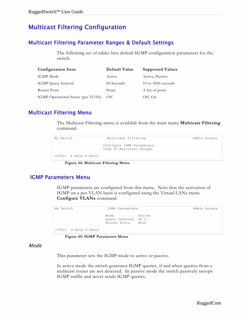
RuggedSwitch™ User Guide
Multicast Filtering Configuration
Multicast Filtering Parameter Ranges & Default Settings
The following set of tables lists default IGMP configuration parameters for the switch.
Configuration Item Default Value Supported Values
IGMP Mode Active Active, Passive
IGMP Query Interval 60 Seconds 10 to 3600 seconds
Router Ports None A list of ports
IGMP Operational Status (per VLAN) Off Off, On
Multicast Filtering Menu
The Multicast Filtering menu is available from the main menu Multicast Filtering command.
Figure 44: Multicast Filtering Menu
IGMP Parameters Menu
IGMP parameters are configured from this menu. Note that the activation of IGMP on a per-VLAN basis is configured using the Virtual LANs menu Configure VLANs command.
Figure 45: IGMP Parameters Menu
My Switch Multicast Filtering Admin Access Configure IGMP Parameters View IP Multicast Groups <CTRL> Z-Help S-Shell
My Switch IGMP Parameters Admin Access Mode Active Query Interval 60 s Router Ports None <CTRL> Z-Help S-Shell
Mode
This parameter sets the IGMP mode to active or passive.
In active mode the switch generates IGMP queries, if and when queries from a multicast router are not detected. In passive mode the switch passively snoops IGMP traffic and never sends IGMP queries.
RuggedCom
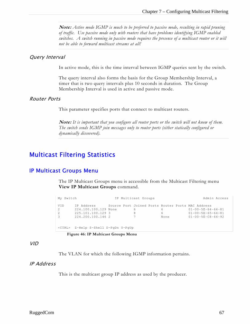
Chapter 7 – Configuring Multicast Filtering
Note: Active mode IGMP is much to be preferred to passive mode, resulting in rapid pruning of traffic. Use passive mode only with routers that have problems identifying IGMP enabled switches. A switch running in passive mode requires the presence of a multicast router or it will not be able to forward multicast streams at all!
Query Interval
In active mode, this is the time interval between IGMP queries sent by the switch.
The query interval also forms the basis for the Group Membership Interval, a timer that is two query intervals plus 10 seconds in duration. The Group Membership Interval is used in active and passive mode.
Router Ports
This parameter specifies ports that connect to multicast routers.
Note: It is important that you configure all router ports or the switch will not know of them. The switch sends IGMP join messages only to router ports (either statically configured or dynamically discovered).
Multicast Filtering Statistics
IP Multicast Groups Menu
The IP Multicast Groups menu is accessible from the Multicast Filtering menu View IP Multicast Groups command.
Figure 46: IP Multicast Groups Menu
My Switch IP Multicast Groups Admin Access VID IP Address Source Port Joined Ports Router Ports MAC Address 2 224.100.100.129 None 6 6 01-00-5E-64-64-81 2 225.101.100.129 3 8 6 01-00-5E-65-64-81 3 224.200.100.146 2 7 None 01-00-5E-C8-64-92 <CTRL> Z-Help S-Shell D-PgDn U-PgUp
VID
The VLAN for which the following IGMP information pertains.
IP Address
This is the multicast group IP address as used by the producer.
RuggedCom 67
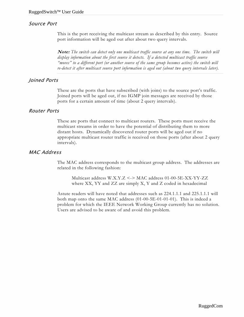
RuggedSwitch™ User Guide
Source Port
This is the port receiving the multicast stream as described by this entry. Source port information will be aged out after about two query intervals.
Note: The switch can detect only one multicast traffic source at any one time. The switch will display information about the first source it detects. If a detected multicast traffic source “moves” to a different port (or another source of the same group becomes active) the switch will re-detect it after multicast source port information is aged out (about two query intervals later).
Joined Ports
These are the ports that have subscribed (with joins) to the source port’s traffic. Joined ports will be aged out, if no IGMP join messages are received by those ports for a certain amount of time (about 2 query intervals).
Router Ports
These are ports that connect to multicast routers. These ports must receive the multicast streams in order to have the potential of distributing them to more distant hosts. Dynamically discovered router ports will be aged out if no appropriate multicast router traffic is received on those ports (after about 2 query intervals).
MAC Address
The MAC address corresponds to the multicast group address. The addresses are related in the following fashion:
Multicast address W.X.Y.Z <-> MAC address 01-00-5E-XX-YY-ZZ where XX, YY and ZZ are simply X, Y and Z coded in hexadecimal
Astute readers will have noted that addresses such as 224.1.1.1 and 225.1.1.1 will both map onto the same MAC address (01-00-5E-01-01-01). This is indeed a problem for which the IEEE Network Working Group currently has no solution. Users are advised to be aware of and avoid this problem.
RuggedCom
Chapter 7 – Configuring Multicast Filtering
Troubleshooting Problem One
• When I start a multicast traffic feed it is always distributed to all members of the VLAN.
Is IGMP enabled for the VLAN? Multicasts will be distributed to all members of the VLAN unless IGMP is enabled.
Problem Two • Computers on my switch receive the multicast traffic just fine, but
I can’t get the stream through a connected router.
Is the port used to connect the router included in the Router Ports parameter of the VLANs menu?
To determine whether the multicast stream is being delivered to the router, run the Ethernet Statistics menu View Ethernet Statistics command. Verify that the traffic count transmitted to the router is same as the traffic count received from the multicasting source.
Problem Three • The video stream at one of my end stations is of pretty poor
quality.
Video serving is a resource-intensive application. Because it uses isochronous workload, data must be fed at a prescribed rate or end users will see glitches in the video. Networks that carry data from the server to the client must be engineered to handle this heavy, isochronous workload.
Video streams can consume large amounts of bandwidth. Features and capacity of both server and network (including routers, bridges, switches, and interfaces) impact the streams.
You should not exceed 60% of the maximum interface bandwidth. For example, if using a 10 Mbps Ethernet, you should run a single multicasting source at no more than 6 Mbps, or two sources at 3 Mbps.
Router ports will carry the traffic of all multicast groups, so it is especially important to consider these ports in your design
Note that multicasting will definitely introduce latency in all traffic on the network. Plan your network carefully in order to account for capacity and latency concerns.
RuggedCom 69
RuggedSwitch™ User Guide
Problem Four • Multicast streams of some groups are not forwarded properly.
Some segments without subscribers receive the traffic while some segments with subscribers don’t.
Ensure there are you do have a situation where differing multicast groups have multicast IP addresses that map to the same multicast MAC Address. The switch forwarding operation is MAC Address based and will not work properly for several groups mapping to the same MAC Address.
Problem Five • Computers on my switch issue join requests but don’t receive
multicast streams from a router.
Is your multicast router running IGMP version 2? It must run IGMP version 2 in order for IGMP Snooping to operate properly.
Problem Six • I connect or disconnect some switch ports and multicast goes
everywhere. Is IGMP broken?
No, it’s a proper switch behaviour. When the switch detects a change in the network topology through RSTP it acts to avoid loss of multicast traffic. It immediately starts issuing its own IGMP queries to quickly obtain group membership information. It also starts forwarding all multicast traffic to all ports that are not Edge Ports (because they may potentially link to routers). This may result in some undesired flooding of multicast traffic, however, it guarantees that all devices interested in the traffic will keep receiving it with no break. The flooding will stop when the “false” router ports are aged out (about 2 switch query intervals). Note that the same behaviour will be observed when the switch resets or when IGMP Snooping is being enabled for the VLAN (in the latter case flooding will only be observed within the VLAN being configured).
RuggedCom
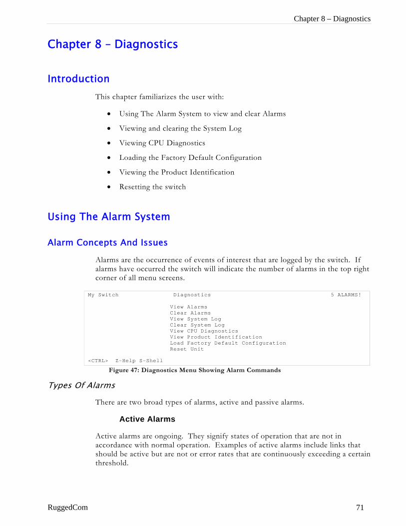
Chapter 8 – Diagnostics
Chapter 8 – Diagnostics
Introduction This chapter familiarizes the user with:
• Using The Alarm System to view and clear Alarms
• Viewing and clearing the System Log
• Viewing CPU Diagnostics
• Loading the Factory Default Configuration
• Viewing the Product Identification
• Resetting the switch
Using The Alarm System
Alarm Concepts And Issues
Alarms are the occurrence of events of interest that are logged by the switch. If alarms have occurred the switch will indicate the number of alarms in the top right corner of all menu screens.
Figure 47: Diagnostics Menu Showing Alarm Commands
My Switch Diagnostics 5 ALARMS! View Alarms Clear Alarms View System Log Clear System Log View CPU Diagnostics View Product Identification Load Factory Default Configuration Reset Unit <CTRL> Z-Help S-Shell
Types Of Alarms
There are two broad types of alarms, active and passive alarms.
Active Alarms
Active alarms are ongoing. They signify states of operation that are not in accordance with normal operation. Examples of active alarms include links that should be active but are not or error rates that are continuously exceeding a certain threshold.
RuggedCom 71
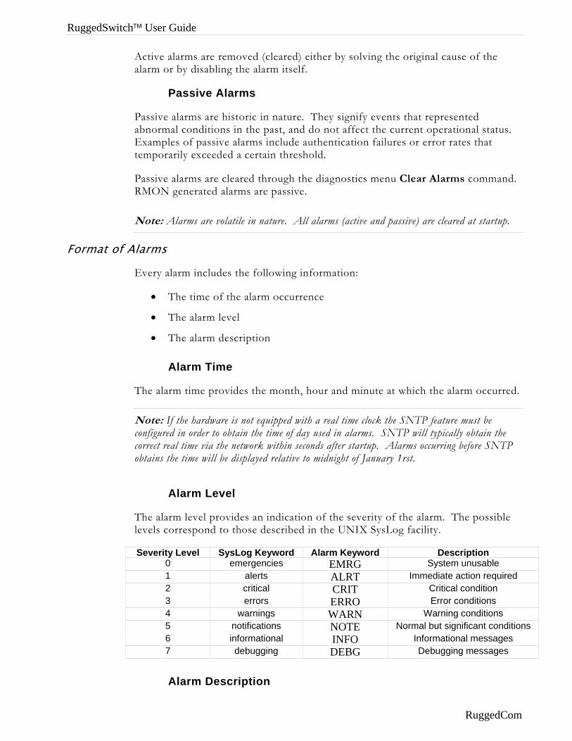
RuggedSwitch™ User Guide
Active alarms are removed (cleared) either by solving the original cause of the alarm or by disabling the alarm itself.
Passive Alarms
Passive alarms are historic in nature. They signify events that represented abnormal conditions in the past, and do not affect the current operational status. Examples of passive alarms include authentication failures or error rates that temporarily exceeded a certain threshold.
Passive alarms are cleared through the diagnostics menu Clear Alarms command. RMON generated alarms are passive.
Note: Alarms are volatile in nature. All alarms (active and passive) are cleared at startup.
Format of Alarms
Every alarm includes the following information:
• The time of the alarm occurrence
• The alarm level
• The alarm description
Alarm Time
The alarm time provides the month, hour and minute at which the alarm occurred.
Note: If the hardware is not equipped with a real time clock the SNTP feature must be configured in order to obtain the time of day used in alarms. SNTP will typically obtain the correct real time via the network within seconds after startup. Alarms occurring before SNTP obtains the time will be displayed relative to midnight of January 1rst.
Alarm Level
The alarm level provides an indication of the severity of the alarm. The possible levels correspond to those described in the UNIX SysLog facility.
Severity Level SysLog Keyword Alarm Keyword Description 0 emergencies EMRG System unusable 1 alerts ALRT Immediate action required 2 critical CRIT Critical condition 3 errors ERRO Error conditions 4 warnings WARN Warning conditions 5 notifications NOTE Normal but significant conditions 6 informational INFO Informational messages 7 debugging DEBG Debugging messages
Alarm Description
RuggedCom

Chapter 8 – Diagnostics
Each alarm has an associated description string. The string will include a port number if it is relevant. The description may also provide an indication of the recent rate at which this alarm is occurring (if the alarm has occurred previously).
Alarms And The Critical Failure Relay
All active alarms will immediately de-energize the critical fail relay (thus signifying a problem). The relay will be re-energized when the last outstanding active alarm is cleared.
Viewing And Clearing Alarms
Viewing Alarms
The Alarms Menu is available from the Diagnostics menu View Alarms command. Alarms are displayed in the order in which they occurred, even if the real time clock was incorrect at the time of the alarm.
Figure 48: Alarms Menu
My Switch Alarms 6 ALARMS! Level Time Description WARN Jan 5 17:55 Port 8 down is occurring (2 times in 192 sec) WARN Jan 5 18:30 Port 13 down has occurred (9 times in 19 hr) WARN Jan 5 19:10 Port 5 is down WARN Jan 6 13:44 Port 7 down has occurred (2 times in 23 hr) WARN Jan 6 17:40 Port 12 was down WARN Jan 6 23:02 Port 6 is down <CTRL> Z-Help S-Shell D-PgDn U-PgUp
Clearing Alarms
The Diagnostics menu Clear Alarms command will clear all alarms.
RuggedCom 73
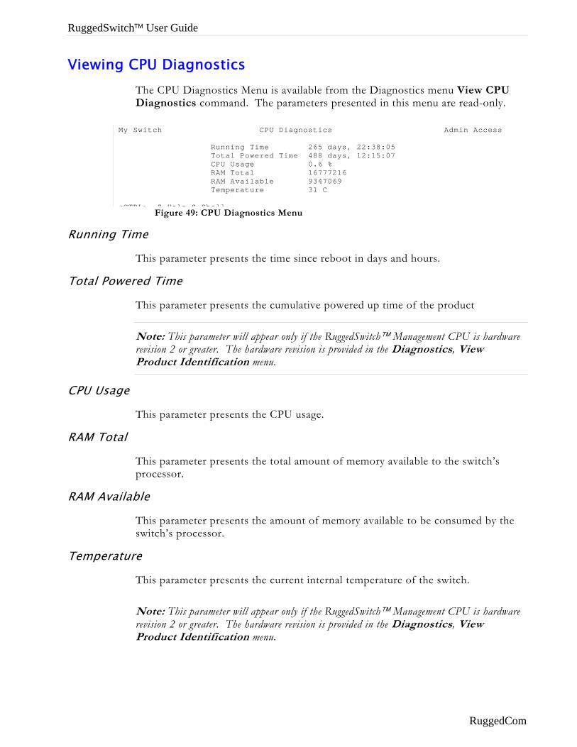
RuggedSwitch™ User Guide
Viewing CPU Diagnostics The CPU Diagnostics Menu is available from the Diagnostics menu View CPU Diagnostics command. The parameters presented in this menu are read-only.
Running
Total Pow
CPU Usag
RAM Tota
RAM Ava
Tempera
Figure 49: CPU Diagnostics Menu
My Switch CPU Diagnostics Admin Access Running Time 265 days, 22:38:05 Total Powered Time 488 days, 12:15:07 CPU Usage 0.6 % RAM Total 16777216 RAM Available 9347069 Temperature 31 C <CTRL> Z Help S Shell
Time
This parameter presents the time since reboot in days and hours.
ered Time
This parameter presents the cumulative powered up time of the product
Note: This parameter will appear only if the RuggedSwitch™ Management CPU is hardware revision 2 or greater. The hardware revision is provided in the Diagnostics, View Product Identification menu.
e
This parameter presents the CPU usage.
l
This parameter presents the total amount of memory available to the switch’s processor.
ilable
This parameter presents the amount of memory available to be consumed by the switch’s processor.
ture
This parameter presents the current internal temperature of the switch.
Note: This parameter will appear only if the RuggedSwitch™ Management CPU is hardware revision 2 or greater. The hardware revision is provided in the Diagnostics, View Product Identification menu.
RuggedCom
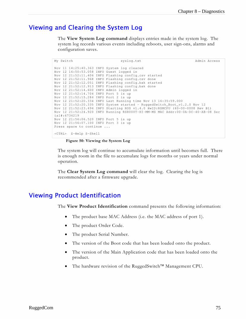
Chapter 8 – Diagnostics
Viewing and Clearing the System Log The View System Log command displays entries made in the system log. The system log records various events including reboots, user sign-ons, alarms and configuration saves.
Figure 50: Viewing the System Log
The system log will continue to accumulate information until becomes full. There is enough room in the file to accumulate logs for months or years under normal operation.
The Clear System Log command will clear the log. Clearing the log is recommended after a firmware upgrade.
My Switch syslog.txt Admin Access Nov 11 14:25:40.363 INFO System log cleared Nov 12 16:50:53.058 INFO Guest logged in Nov 12 21:52:11.406 INFO Flashing config.csv started Nov 12 21:52:11.968 INFO Flashing config.csv done Nov 12 21:52:12.051 INFO Flashing config.bak started Nov 12 21:52:12.913 INFO Flashing config.bak done Nov 12 21:52:14.600 INFO Admin logged in Nov 12 21:52:14.704 INFO Port 5 is up Nov 12 21:52:15.284 INFO Port 2 is up Nov 12 21:52:20.334 INFO Last Running time Nov 13 16:35:59.000 Nov 12 21:52:20.335 INFO System started - RuggedSwitch_Boot_v1.2.0 Nov 12 Nov 12 21:52:23.494 INFO Starting ROS v1.4.0 HwID:RSMCPU (40-00-0008 Rev B1) Nov 12 21:52:24.920 INFO Running RS8000T-HI-MM-MS MAC Addr:00-0A-DC-40-AB-08 Ser ial#:6734219 Nov 12 21:56:06.520 INFO Port 5 is up Nov 12 21:56:07.100 INFO Port 3 is up Press space to continue ... <CTRL> Z-Help S-Shell
Viewing Product Identification The View Product Identification command presents the following information:
• The product base MAC Address (i.e. the MAC address of port 1).
• The product Order Code.
• The product Serial Number.
• The version of the Boot code that has been loaded onto the product.
• The version of the Main Application code that has been loaded onto the product.
• The hardware revision of the RuggedSwitch™ Management CPU.
RuggedCom 75
RuggedSwitch™ User Guide
Load Factory Default Configuration The Load Factory Default Configuration command will re-load all configuration parameters to factory default values. Configuration parameters that affect the connection to the switch (as provided by the Configure IP Services menu) will not be modified. A prompt will be displayed requesting confirmation of this action.
Resetting The Unit The Reset Device command will close all open Telnet connections and warm start the unit.
RuggedCom
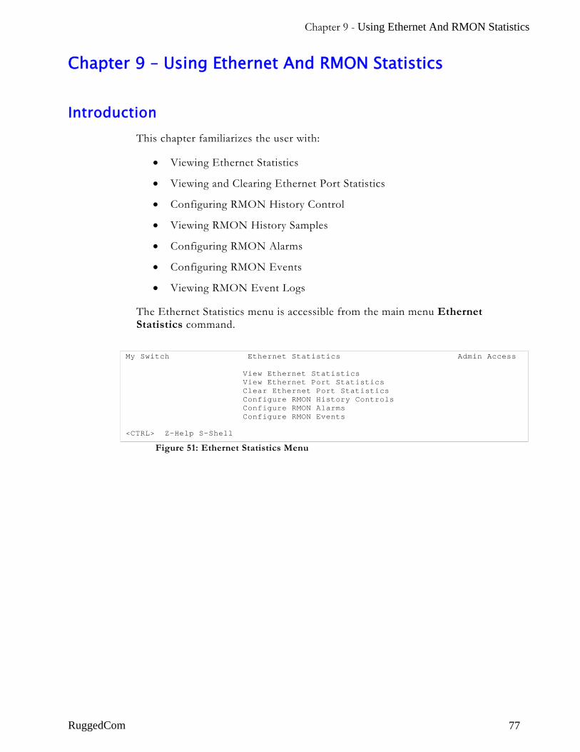
Chapter 9 - Using Ethernet And RMON Statistics
Chapter 9 – Using Ethernet And RMON Statistics
Introduction This chapter familiarizes the user with:
• Viewing Ethernet Statistics
• Viewing and Clearing Ethernet Port Statistics
• Configuring RMON History Control
• Viewing RMON History Samples
• Configuring RMON Alarms
• Configuring RMON Events
• Viewing RMON Event Logs
The Ethernet Statistics menu is accessible from the main menu Ethernet Statistics command.
Figure 51: Ethernet Statistics Menu
My Switch Ethernet Statistics Admin Access View Ethernet Statistics View Ethernet Port Statistics Clear Ethernet Port Statistics Configure RMON History Controls Configure RMON Alarms Configure RMON Events <CTRL> Z-Help S-Shell
RuggedCom 77
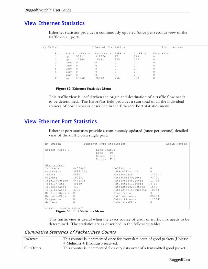
RuggedSwitch™ User Guide
View Ethernet Statistics Ethernet statistics provides a continuously updated (once per second) view of the traffic on all ports.
View Et
CumulatiInOctets
OutOctets
Figure 52: Ethernet Statistics Menu
My Switch Ethernet Statistics Admin Access Port State InOctets OutOctets InPkts OutPkts ErrorPkts 1 Up 53412 319576 47 519 0 2 Up 17600 15482 275 247 0 3 Down 0 0 0 0 0 4 Down 0 0 0 0 0 5 Down 0 0 0 0 0 6 Down 0 0 0 0 0 7 Down 0 0 0 0 0 8 Up 55068 70012 766 322 0
This traffic view is useful when the origin and destination of a traffic flow needs to be determined. The ErrorPkts field provides a sum total of all the individual sources of port errors as described in the Ethernet Port statistics menu.
hernet Port Statistics Ethernet port statistics provide a continuously updated (once per second) detailed view of the traffic on a single port.
v
M S SIOIOTTIICOFJ <
Figure 53: Port Statistics Menu
y Switch Ethernet Port Statistics Admin Access
elect Port: 3 Link Status: Link Up Speed 100 Duplex Full
tatistics: nOctets 8436846 Collisions 0 utOctets 38272361 LateCollisions 0 nPkts 40811 Pkt64Octets 137413 utPkts 190282 Pkt65to127Octets 53701 otalInOctets 8442416 Pkt128to255Octets 13792 otalInPkts 40860 Pkt256to511Octets 5737 nBroadcasts 439 Pkt512to1023Octets 1540 nMulticasts 3391 Pkt1024to1536Octets 18959 RCAlignErrors 0 DropEvents 0 versizePkts 0 OutBroadcasts 25259 ragments 0 OutMulticasts 119281 abbers 0 UndersizePkts 0
CTRL> Z-Help S-Shell
This traffic view is useful when the exact source of error or traffic mix needs to be determined. The statistics are as described in the following tables.
e Statistics of Packet/Byte Counts This counter is incremented once for every data octet of good packets (Unicast + Multicast + Broadcast) received. This counter is incremented for every data octet of a transmitted good packet.
RuggedCom
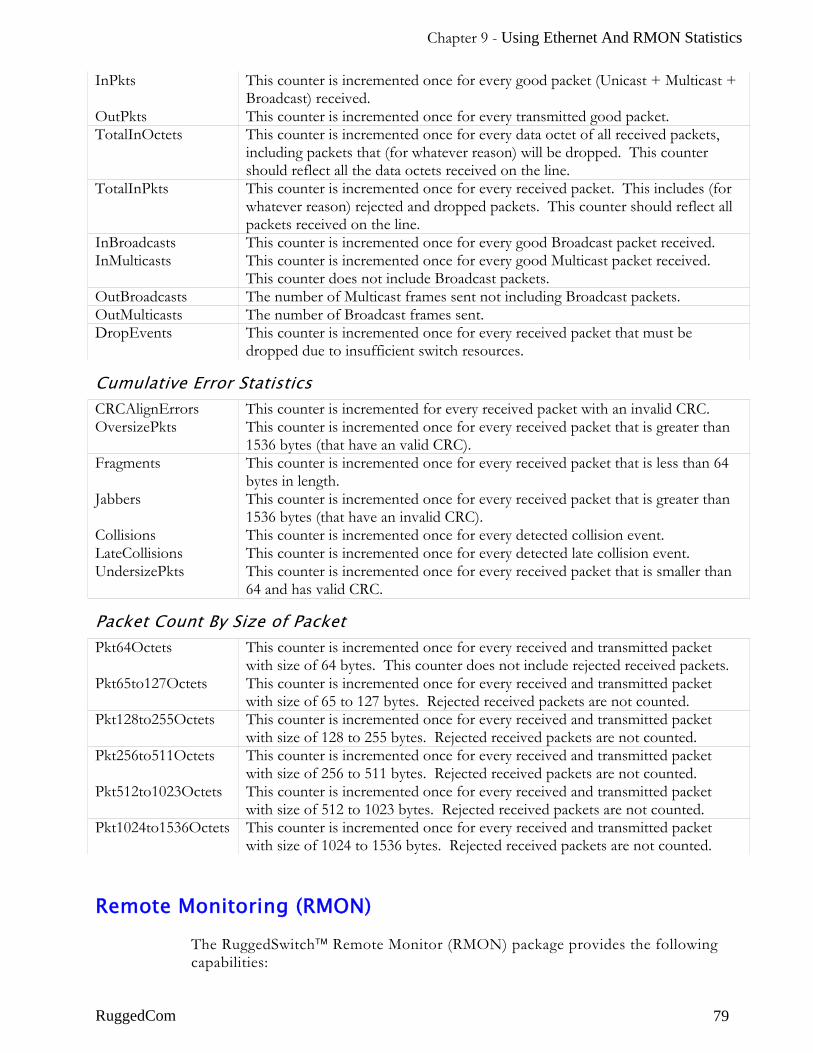
Chapter 9 - Using Ethernet And RMON Statistics
InPkts This counter is incremented once for every good packet (Unicast + Multicast + Broadcast) received.
OutPkts This counter is incremented once for every transmitted good packet. TotalInOctets This counter is incremented once for every data octet of all received packets,
including packets that (for whatever reason) will be dropped. This counter should reflect all the data octets received on the line.
TotalInPkts This counter is incremented once for every received packet. This includes (for whatever reason) rejected and dropped packets. This counter should reflect all packets received on the line.
InBroadcasts This counter is incremented once for every good Broadcast packet received. InMulticasts This counter is incremented once for every good Multicast packet received.
This counter does not include Broadcast packets. OutBroadcasts The number of Multicast frames sent not including Broadcast packets. OutMulticasts The number of Broadcast frames sent. DropEvents This counter is incremented once for every received packet that must be
dropped due to insufficient switch resources.
Cumulative Error Statistics CRCAlignErrors This counter is incremented for every received packet with an invalid CRC. OversizePkts This counter is incremented once for every received packet that is greater than
1536 bytes (that have an valid CRC). Fragments This counter is incremented once for every received packet that is less than 64
bytes in length. Jabbers This counter is incremented once for every received packet that is greater than
1536 bytes (that have an invalid CRC). Collisions This counter is incremented once for every detected collision event. LateCollisions This counter is incremented once for every detected late collision event. UndersizePkts This counter is incremented once for every received packet that is smaller than
64 and has valid CRC.
Packet Count By Size of Packet Pkt64Octets This counter is incremented once for every received and transmitted packet
with size of 64 bytes. This counter does not include rejected received packets. Pkt65to127Octets This counter is incremented once for every received and transmitted packet
with size of 65 to 127 bytes. Rejected received packets are not counted. Pkt128to255Octets This counter is incremented once for every received and transmitted packet
with size of 128 to 255 bytes. Rejected received packets are not counted. Pkt256to511Octets This counter is incremented once for every received and transmitted packet
with size of 256 to 511 bytes. Rejected received packets are not counted. Pkt512to1023Octets This counter is incremented once for every received and transmitted packet
with size of 512 to 1023 bytes. Rejected received packets are not counted. Pkt1024to1536Octets This counter is incremented once for every received and transmitted packet
with size of 1024 to 1536 bytes. Rejected received packets are not counted.
Remote Monitoring (RMON)
The RuggedSwitch™ Remote Monitor (RMON) package provides the following capabilities:
RuggedCom 79
RuggedSwitch™ User Guide
• The ability to collect historical statistics in order to review performance and operation of Ethernet ports.
• The ability to record a log entry and/or generate an SNMP trap when the rate of occurrence of a specified event is exceeded.
These capabilities are provided through the following menus:
• RMON History Control Table – This menu controls the periodic statistical sampling of data and corresponds to the RFC 2819 (RMON-MIB) History Group.
• RMON History Samples Table – Reached through the History control menu, this menu provides the ability to view collected history samples of statistics on the Ethernet interface. These samples corresponds to the RFC 2819 (RMON-MIB) Ethernet History Group.
• RMON Alarms Table – Monitors a specific management information base (MIB) object for a specified interval, generates an alarm at a specified value (rising threshold or falling threshold). Alarms are logged in the switch alarm menu and can be used to triggers RMON events.
• RMON Events Table – Determines the action to take when an event is triggered by an alarm. The action can be to generate a log entry and/or an SNMP trap.
• RMON Events Logs Table - Reached through the RMON Events Table menu, this menu provides the ability to view collected logs.
RuggedCom
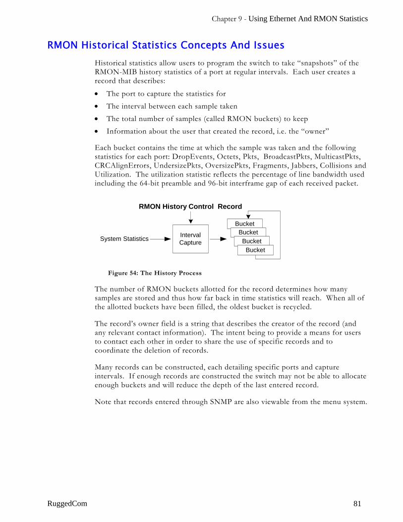
Chapter 9 - Using Ethernet And RMON Statistics
RMON Historical Statistics Concepts And Issues Historical statistics allow users to program the switch to take “snapshots” of the RMON-MIB history statistics of a port at regular intervals. Each user creates a record that describes:
• The port to capture the statistics for • The interval between each sample taken • The total number of samples (called RMON buckets) to keep • Information about the user that created the record, i.e. the “owner”
Each bucket contains the time at which the sample was taken and the following statistics for each port: DropEvents, Octets, Pkts, BroadcastPkts, MulticastPkts, CRCAlignErrors, UndersizePkts, OversizePkts, Fragments, Jabbers, Collisions and Utilization. The utilization statistic reflects the percentage of line bandwidth used including the 64-bit preamble and 96-bit interframe gap of each received packet.
System Statistics
RMON History Control Record
IntervalCapture
BucketBucketBucket
Bucket
Figure 54: The History Process
The number of RMON buckets allotted for the record determines how many samples are stored and thus how far back in time statistics will reach. When all of the allotted buckets have been filled, the oldest bucket is recycled.
The record’s owner field is a string that describes the creator of the record (and any relevant contact information). The intent being to provide a means for users to contact each other in order to share the use of specific records and to coordinate the deletion of records.
Many records can be constructed, each detailing specific ports and capture intervals. If enough records are constructed the switch may not be able to allocate enough buckets and will reduce the depth of the last entered record.
Note that records entered through SNMP are also viewable from the menu system.
RuggedCom 81
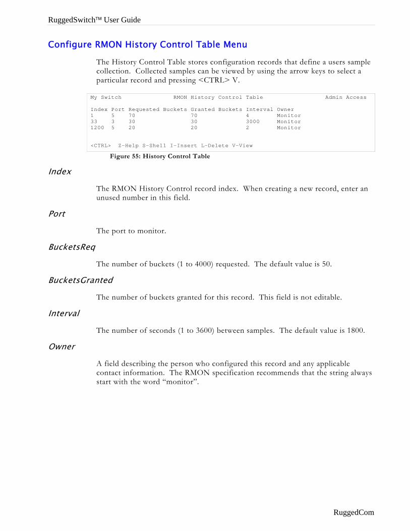
RuggedSwitch™ User Guide
Configure RMON History Control Table Menu
The History Control Table stores configuration records that define a users sample collection. Collected samples can be viewed by using the arrow keys to select a particular record and pressing <CTRL> V.
Figure 55: History Control Table
My Switch RMON History Control Table Admin Access Index Port Requested Buckets Granted Buckets Interval Owner 1 5 70 70 4 Monitor 33 3 30 30 3000 Monitor 1200 5 20 20 2 Monitor <CTRL> Z-Help S-Shell I-Insert L-Delete V-View
Index
The RMON History Control record index. When creating a new record, enter an unused number in this field.
Port
The port to monitor.
BucketsReq
The number of buckets (1 to 4000) requested. The default value is 50.
BucketsGranted
The number of buckets granted for this record. This field is not editable.
Interval
The number of seconds (1 to 3600) between samples. The default value is 1800.
Owner
A field describing the person who configured this record and any applicable contact information. The RMON specification recommends that the string always start with the word “monitor”.
RuggedCom
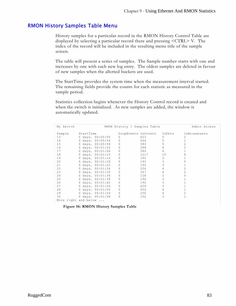
Chapter 9 - Using Ethernet And RMON Statistics
RMON History Samples Table Menu
History samples for a particular record in the RMON History Control Table are displayed by selecting a particular record there and pressing <CTRL> V. The index of the record will be included in the resulting menu title of the sample screen.
The table will present a series of samples. The Sample number starts with one and increases by one with each new log entry. The oldest samples are deleted in favour of new samples when the allotted buckets are used.
The StartTime provides the system time when the measurement interval started. The remaining fields provide the counts for each statistic as measured in the sample period.
Statistics collection begins whenever the History Control record is created and when the switch is initialized. As new samples are added, the window is automatically updated.
RuggedCom
Figure 56: RMON History Samples Table
My Switch RMON History 1 Samples Table Admin Access Sample StartTime DropEvents InOctets InPkts InBroadcasts 13 0 days, 00:00:50 0 623 5 2 14 0 days, 00:00:54 0 446 5 1 15 0 days, 00:00:58 0 383 5 2 16 0 days, 00:01:02 0 288 4 2 17 0 days, 00:01:06 0 384 6 1 18 0 days, 00:01:10 0 1217 10 8 19 0 days, 00:01:14 0 192 3 1 20 0 days, 00:01:18 0 193 3 0 21 0 days, 00:01:22 0 192 3 1 22 0 days, 00:01:26 0 256 4 2 23 0 days, 00:01:30 0 367 4 2 24 0 days, 00:01:34 0 128 2 0 25 0 days, 00:01:38 0 192 3 1 26 0 days, 00:01:42 0 192 3 1 27 0 days, 00:01:46 0 629 5 1 28 0 days, 00:01:50 0 502 4 1 29 0 days, 00:01:54 0 256 4 2 30 0 days, 00:01:58 0 192 3 1 More right and below ...
83
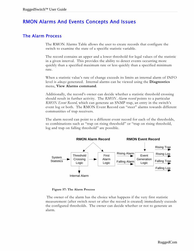
RuggedSwitch™ User Guide
RMON Alarms And Events Concepts And Issues
The Alarm Process
The RMON Alarms Table allows the user to create records that configure the switch to examine the state of a specific statistic variable.
The record contains an upper and a lower threshold for legal values of the statistic in a given interval. This provides the ability to detect events occurring more quickly than a specified maximum rate or less quickly than a specified minimum rate.
When a statistic value’s rate of change exceeds its limits an internal alarm of INFO level is always generated. Internal alarms can be viewed using the Diagnostics menu, View Alarms command.
Additionally, the record’s owner can decide whether a statistic threshold crossing should result in further activity. The RMON Alarm record points to a particular RMON Event Record, which can generate an SNMP trap, an entry in the switch’s event log or both. The RMON Event Record can “steer” alarms towards different communities of trap receivers.
The alarm record can point to a different event record for each of the thresholds, so combinations such as “trap on rising threshold” or “trap on rising threshold, log and trap on falling threshold” are possible.
SystemStatistics
Internal Alarm
RMON Alarm Record RMON Event Record
Rising Alarm
Falling Alarm
Rising Trap
Rising Log
Falling Trap
Falling Log
ThresholdCrossing
Logic
FirstAlarmLogic
EventGeneration
Logic
Figure 57: The Alarm Process
The owner of the alarm has the choice what happens if the very first statistic measurement (after switch reset or after the record is created) immediately exceeds the configured thresholds. The owner can decide whether or not to generate an alarm.
RuggedCom
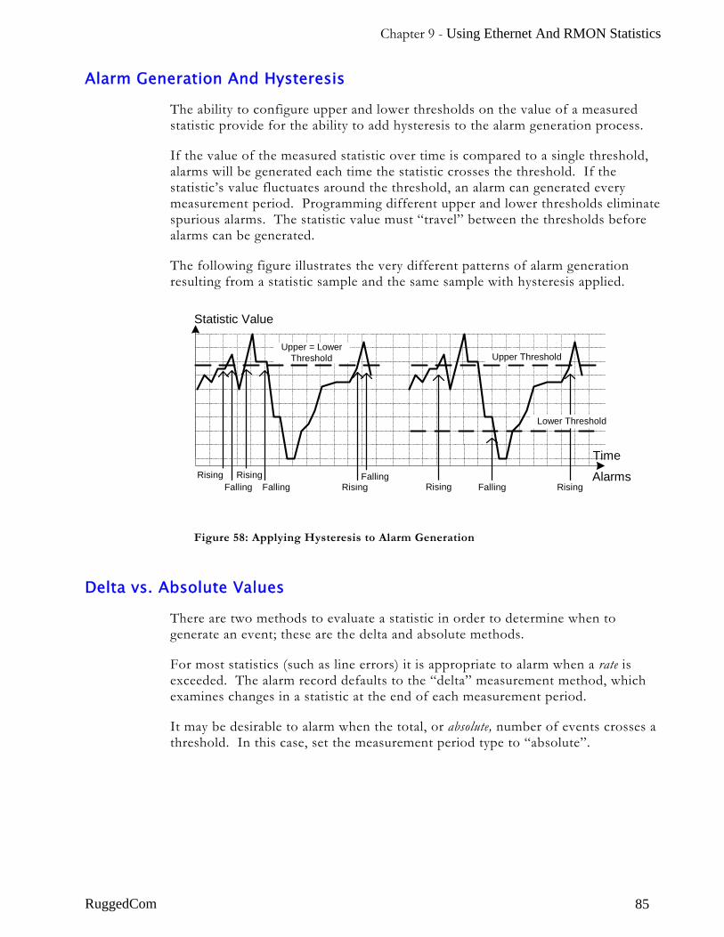
Chapter 9 - Using Ethernet And RMON Statistics
Alarm Generation And Hysteresis
The ability to configure upper and lower thresholds on the value of a measured statistic provide for the ability to add hysteresis to the alarm generation process.
If the value of the measured statistic over time is compared to a single threshold, alarms will be generated each time the statistic crosses the threshold. If the statistic’s value fluctuates around the threshold, an alarm can generated every measurement period. Programming different upper and lower thresholds eliminate spurious alarms. The statistic value must “travel” between the thresholds before alarms can be generated.
The following figure illustrates the very different patterns of alarm generation resulting from a statistic sample and the same sample with hysteresis applied.
Statistic Value
Time
Upper ThresholdUpper = Lower
Threshold
Lower Threshold
AlarmsRising RisingFalling
Rising RisingFalling Rising
FallingFalling
Figure 58: Applying Hysteresis to Alarm Generation
Delta vs. Absolute Values
There are two methods to evaluate a statistic in order to determine when to generate an event; these are the delta and absolute methods.
For most statistics (such as line errors) it is appropriate to alarm when a rate is exceeded. The alarm record defaults to the “delta” measurement method, which examines changes in a statistic at the end of each measurement period.
It may be desirable to alarm when the total, or absolute, number of events crosses a threshold. In this case, set the measurement period type to “absolute”.
RuggedCom 85
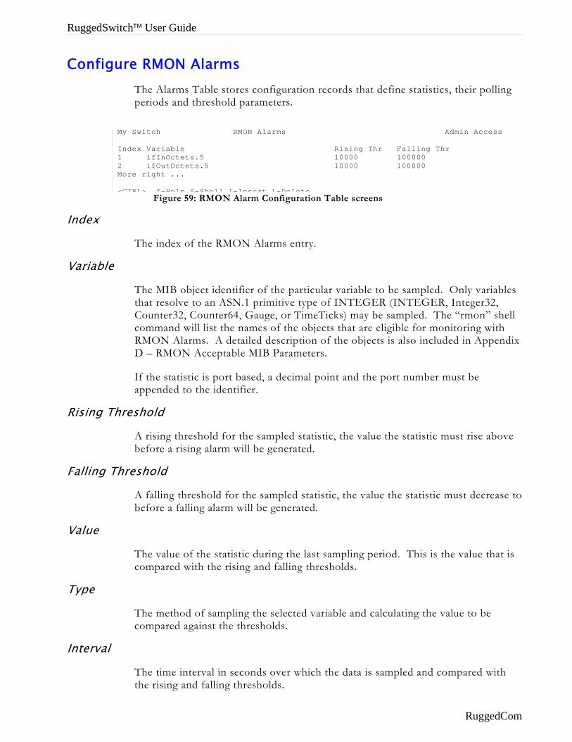
RuggedSwitch™ User Guide
Configure RMON Alarms The Alarms Table stores configuration records that define statistics, their polling periods and threshold parameters.
Index
Variable
Rising Th
Falling Th
Value
Type
Interval
Figure 59: RMON Alarm Configuration Table screens
My Switch RMON Alarms Admin Access Index Variable Rising Thr Falling Thr 1 ifInOctets.5 10000 100000 2 ifOutOctets.5 10000 100000 More right ... <CTRL> Z-Help S-Shell I-Insert L-Delete
The index of the RMON Alarms entry.
The MIB object identifier of the particular variable to be sampled. Only variables that resolve to an ASN.1 primitive type of INTEGER (INTEGER, Integer32, Counter32, Counter64, Gauge, or TimeTicks) may be sampled. The “rmon” shell command will list the names of the objects that are eligible for monitoring with RMON Alarms. A detailed description of the objects is also included in Appendix D – RMON Acceptable MIB Parameters.
If the statistic is port based, a decimal point and the port number must be appended to the identifier.
reshold
A rising threshold for the sampled statistic, the value the statistic must rise above before a rising alarm will be generated.
reshold
A falling threshold for the sampled statistic, the value the statistic must decrease to before a falling alarm will be generated.
The value of the statistic during the last sampling period. This is the value that is compared with the rising and falling thresholds.
The method of sampling the selected variable and calculating the value to be compared against the thresholds.
The time interval in seconds over which the data is sampled and compared with the rising and falling thresholds.
RuggedCom
Chapter 9 - Using Ethernet And RMON Statistics
Startup Alarm
The alarm that may be sent after the first measurement period. If the first sample is greater than or equal to the rising threshold and Startup Alarm is equal to “rising” or “risingOrFalling”, then a rising alarm will be generated. If the first is less than or equal to the falling threshold and Startup Alarm is equal to “falling” or “risingOrFalling”, then a falling alarm will be generated.
Rising Event
The index of the RMON Events Table entry that is used when a rising threshold is crossed. If this value is zero or if there is no corresponding entry in the RMON Events Table, then no alarm will be generated.
Falling Event
The index of the RMON Events Table entry that is used when a falling threshold is reached. If this value is zero or if there is no corresponding entry in the RMON Events Table, then no alarm will be generated.
Owner
A field describing the person who configured this record and any applicable contact information. The RMON specification recommends that the string always start with the word “monitor”.
RuggedCom 87
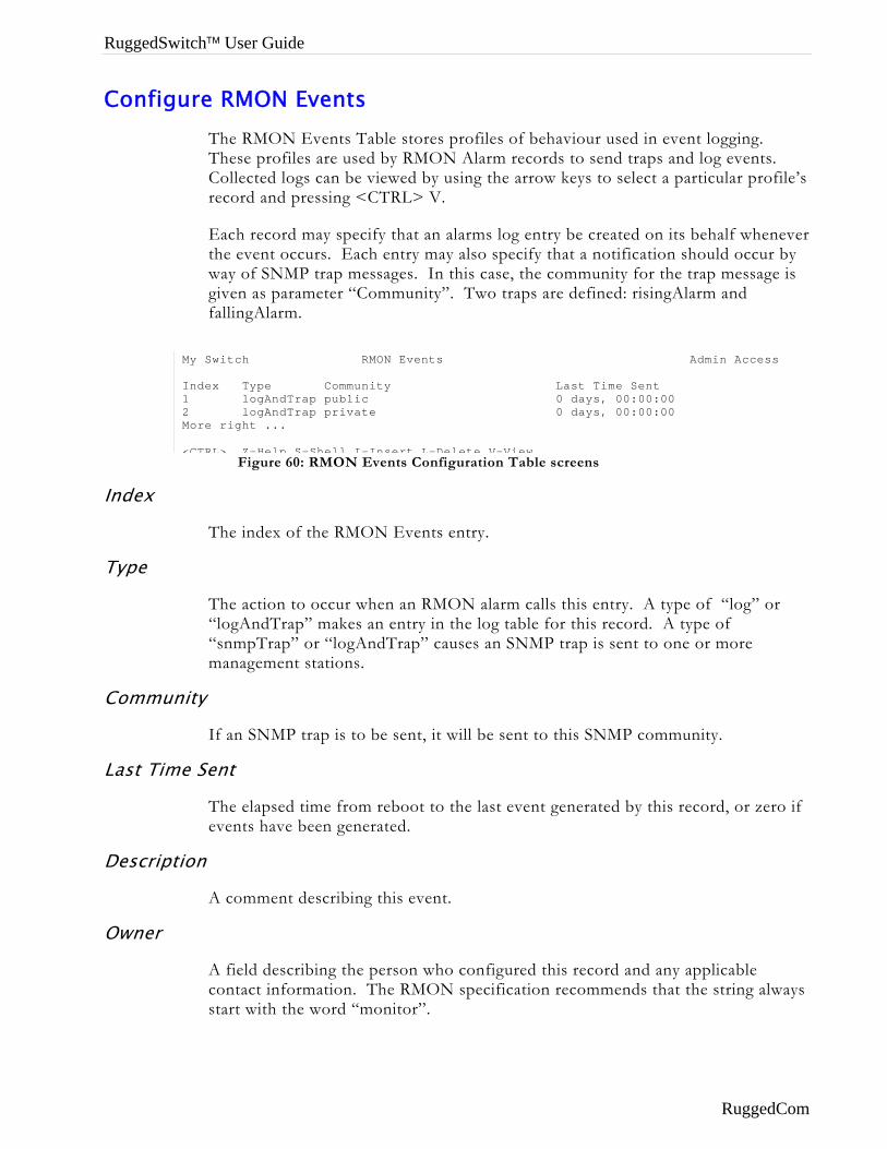
RuggedSwitch™ User Guide
Configure RMON Events The RMON Events Table stores profiles of behaviour used in event logging. These profiles are used by RMON Alarm records to send traps and log events. Collected logs can be viewed by using the arrow keys to select a particular profile’s record and pressing <CTRL> V.
Each record may specify that an alarms log entry be created on its behalf whenever the event occurs. Each entry may also specify that a notification should occur by way of SNMP trap messages. In this case, the community for the trap message is given as parameter “Community”. Two traps are defined: risingAlarm and fallingAlarm.
Index
Type
Commun
Last Time
Descripti
Owner
Figure 60: RMON Events Configuration Table screens
My Switch RMON Events Admin Access Index Type Community Last Time Sent 1 logAndTrap public 0 days, 00:00:00 2 logAndTrap private 0 days, 00:00:00 More right ... <CTRL> Z-Help S-Shell I-Insert L-Delete V-View
The index of the RMON Events entry.
The action to occur when an RMON alarm calls this entry. A type of “log” or “logAndTrap” makes an entry in the log table for this record. A type of “snmpTrap” or “logAndTrap” causes an SNMP trap is sent to one or more management stations.
ity
If an SNMP trap is to be sent, it will be sent to this SNMP community.
Sent
The elapsed time from reboot to the last event generated by this record, or zero if events have been generated.
on
A comment describing this event.
A field describing the person who configured this record and any applicable contact information. The RMON specification recommends that the string always start with the word “monitor”.
RuggedCom
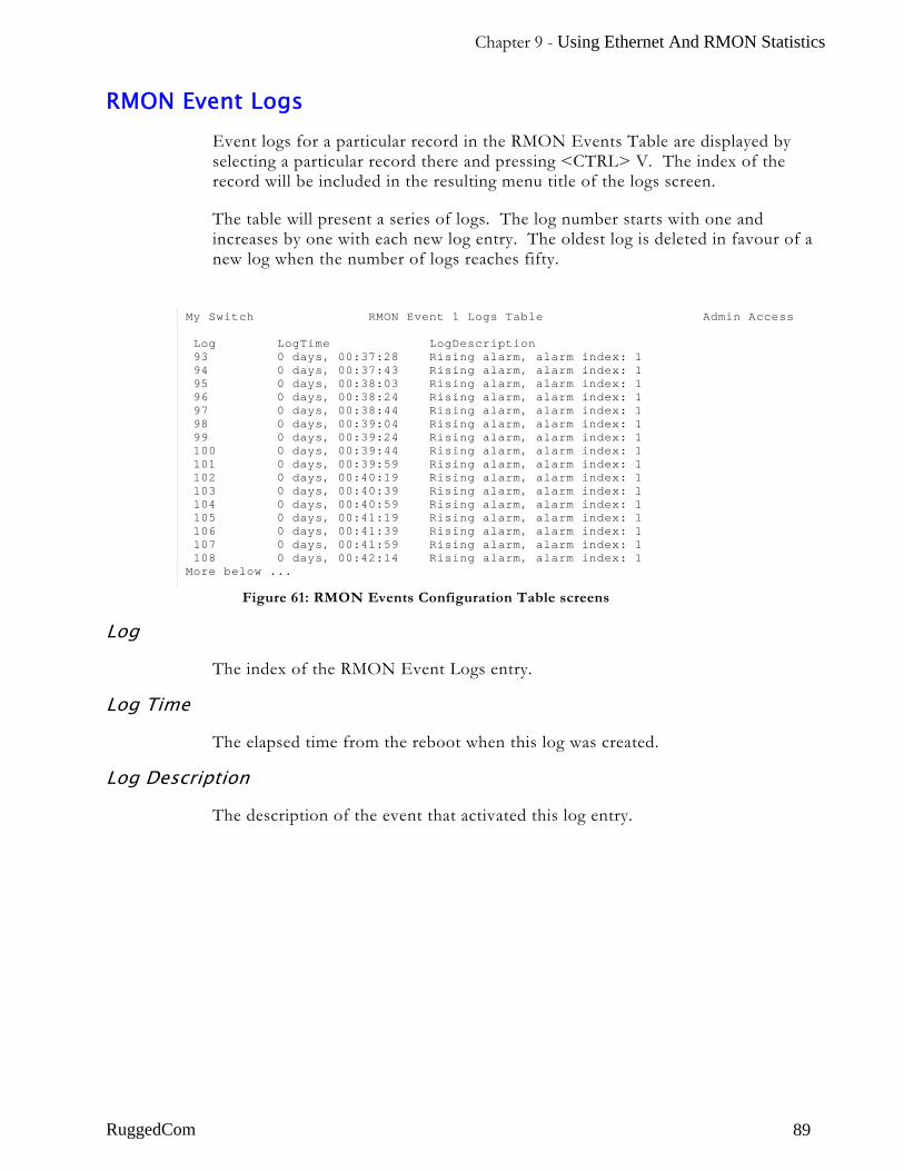
Chapter 9 - Using Ethernet And RMON Statistics
RMON Event Logs Event logs for a particular record in the RMON Events Table are displayed by selecting a particular record there and pressing <CTRL> V. The index of the record will be included in the resulting menu title of the logs screen.
The table will present a series of logs. The log number starts with one and increases by one with each new log entry. The oldest log is deleted in favour of a new log when the number of logs reaches fifty.
Figure 61: RMON Events Configuration Table screens
My Switch RMON Event 1 Logs Table Admin Access Log LogTime LogDescription 93 0 days, 00:37:28 Rising alarm, alarm index: 1 94 0 days, 00:37:43 Rising alarm, alarm index: 1 95 0 days, 00:38:03 Rising alarm, alarm index: 1 96 0 days, 00:38:24 Rising alarm, alarm index: 1 97 0 days, 00:38:44 Rising alarm, alarm index: 1 98 0 days, 00:39:04 Rising alarm, alarm index: 1 99 0 days, 00:39:24 Rising alarm, alarm index: 1 100 0 days, 00:39:44 Rising alarm, alarm index: 1 101 0 days, 00:39:59 Rising alarm, alarm index: 1 102 0 days, 00:40:19 Rising alarm, alarm index: 1 103 0 days, 00:40:39 Rising alarm, alarm index: 1 104 0 days, 00:40:59 Rising alarm, alarm index: 1 105 0 days, 00:41:19 Rising alarm, alarm index: 1 106 0 days, 00:41:39 Rising alarm, alarm index: 1 107 0 days, 00:41:59 Rising alarm, alarm index: 1 108 0 days, 00:42:14 Rising alarm, alarm index: 1 More below ...
Log
The index of the RMON Event Logs entry.
Log Time
The elapsed time from the reboot when this log was created.
Log Description
The description of the event that activated this log entry.
RuggedCom 89
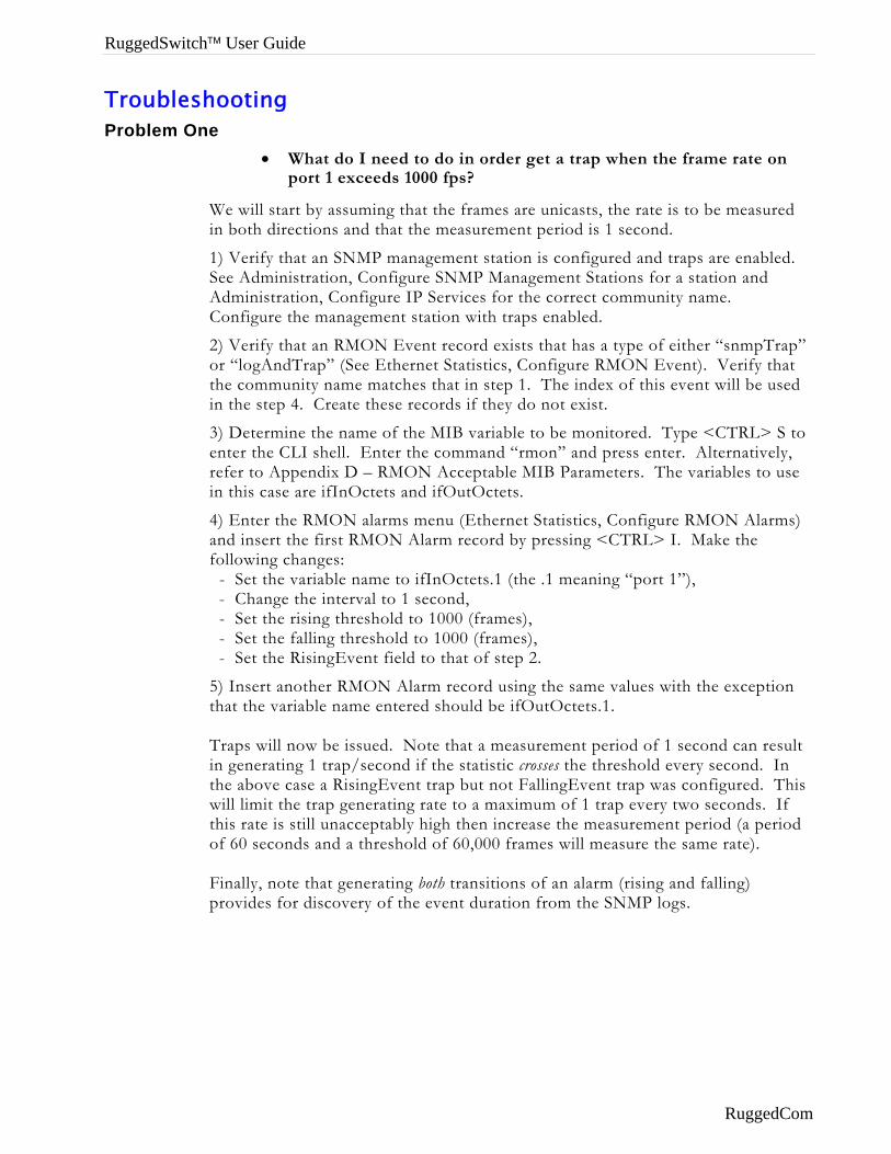
RuggedSwitch™ User Guide
Troubleshooting Problem One
• What do I need to do in order get a trap when the frame rate on port 1 exceeds 1000 fps?
We will start by assuming that the frames are unicasts, the rate is to be measured in both directions and that the measurement period is 1 second.
1) Verify that an SNMP management station is configured and traps are enabled. See Administration, Configure SNMP Management Stations for a station and Administration, Configure IP Services for the correct community name. Configure the management station with traps enabled.
2) Verify that an RMON Event record exists that has a type of either “snmpTrap” or “logAndTrap” (See Ethernet Statistics, Configure RMON Event). Verify that the community name matches that in step 1. The index of this event will be used in the step 4. Create these records if they do not exist.
3) Determine the name of the MIB variable to be monitored. Type <CTRL> S to enter the CLI shell. Enter the command “rmon” and press enter. Alternatively, refer to Appendix D – RMON Acceptable MIB Parameters. The variables to use in this case are ifInOctets and ifOutOctets.
4) Enter the RMON alarms menu (Ethernet Statistics, Configure RMON Alarms) and insert the first RMON Alarm record by pressing <CTRL> I. Make the following changes: - Set the variable name to ifInOctets.1 (the .1 meaning “port 1”), - Change the interval to 1 second, - Set the rising threshold to 1000 (frames), - Set the falling threshold to 1000 (frames), - Set the RisingEvent field to that of step 2.
5) Insert another RMON Alarm record using the same values with the exception that the variable name entered should be ifOutOctets.1. Traps will now be issued. Note that a measurement period of 1 second can result in generating 1 trap/second if the statistic crosses the threshold every second. In the above case a RisingEvent trap but not FallingEvent trap was configured. This will limit the trap generating rate to a maximum of 1 trap every two seconds. If this rate is still unacceptably high then increase the measurement period (a period of 60 seconds and a threshold of 60,000 frames will measure the same rate). Finally, note that generating both transitions of an alarm (rising and falling) provides for discovery of the event duration from the SNMP logs.
RuggedCom
Chapter 10 - Using The CLI Shell
Chapter 10 - Using The CLI Shell
Introduction This chapter familiarizes the user with:
• Entering and leaving the CLI shell
• Viewing files contained in the RuggedSwitch™ File System
• Viewing and clearing log files
• Running a Loopback test
• Pinging remote devices
• Tracing the operation of certain protocols
• Viewing DHCP Learned Information Using Ipconfig
• Executing Commands Remotely Through RSH
• Resetting the switch
Note: The operations described in this chapter are available to users at the guest, operator or administrator security level. The XModem and TFTP file transfer utilities are available only to operators and administrators and are described in the chapter “Upgrading Firmware And Managing Configurations”. The SQL command is available to users at the administrator level and is also described in “Upgrading Firmware And Managing Configurations”.
Entering And Leaving The Shell You may enter the Command Line Interface (CLI) shell from any and all menus by pressing <CTRL> S. Any menu operation in progress (such as changing a configuration parameter) will be terminated. You may return to the menu system by pressing <CTRL> S or entering “exit<CR>” at the shell prompt.
RuggedCom 91
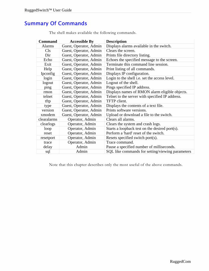
RuggedSwitch™ User Guide
Summary Of Commands The shell makes available the following commands.
Command Accessible By Description Alarms Guest, Operator, Admin Displays alarms available in the switch.
Cls Guest, Operator, Admin Clears the screen. Dir Guest, Operator, Admin Prints file directory listing.
Echo Guest, Operator, Admin Echoes the specified message to the screen. Exit Guest, Operator, Admin Terminate this command line session. Help Guest, Operator, Admin Print listing of all commands.
Ipconfig Guest, Operator, Admin Displays IP configuration. login Guest, Operator, Admin Login to the shell i.e. set the access level. logout Guest, Operator, Admin Logout of the shell. ping Guest, Operator, Admin Pings specified IP address. rmon Guest, Operator, Admin Displays names of RMON alarm eligible objects. telnet Guest, Operator, Admin Telnet to the server with specified IP address. tftp Guest, Operator, Admin TFTP client. type Guest, Operator, Admin Displays the contents of a text file.
version Guest, Operator, Admin Prints software versions. xmodem Guest, Operator, Admin Upload or download a file to the switch.
clearalarms Operator, Admin Clears all alarms. clearlogs Operator, Admin Clears the system and crash logs.
loop Operator, Admin Starts a loopback test on the desired port(s). reset Operator, Admin Perform a 'hard' reset of the switch.
resetport Operator, Admin Resets specified switch port(s). trace Operator, Admin Trace command. delay Admin Pause a specified number of milliseconds. sql Admin SQL like commands for setting/viewing parameters
Note that this chapter describes only the most useful of the above commands.
RuggedCom
Chapter 10 - Using The CLI Shell
Viewing Files
The RuggedSwitch™ maintains a number of volatile and nonvolatile files. These files can aid in the resolution of problems and serve as a useful gauge of the switch’s health.
Dir command
Enter “dir<CR>” to obtain a complete list of files and a description of each.
Note: Each file has associated attributes, as described under the Attr column. Files marked “R” are readable, i.e. may be uploaded by the user. Files marked “W” are writable, i.e. may be modified (downloaded) by the user. Files marked “B” are binary files, i.e. may be upgraded by the user.
The most useful files include config.csv, crashlog.txt and syslog.txt. These files may be viewed by using the “type” command, specifying the desired filename.
The config.csv file contains the current configuration settings. The use of this file is described in the chapter “Upgrading Firmware And Managing Configurations”.
Viewing And Clearing Log Files
The crashlog.txt and syslog.txt files contain historical information about events that have occurred.
The crashlog.txt file will contain debugging information relating to problems that have resulted in unplanned restarts of the switch. A file size of 0 bytes indicates that no untoward events have occurred.
The syslog.txt file contains a record of significant events including startups, configuration modifications, firmware upgrades and database re-initializations due to feature additions. The syslog will accumulate information until it fills, holding approximately 3 megabytes of characters.
The “clearlogs” command will reset these logs. It is recommended to run the clearlogs command after every firmware upgrade.
RuggedCom 93
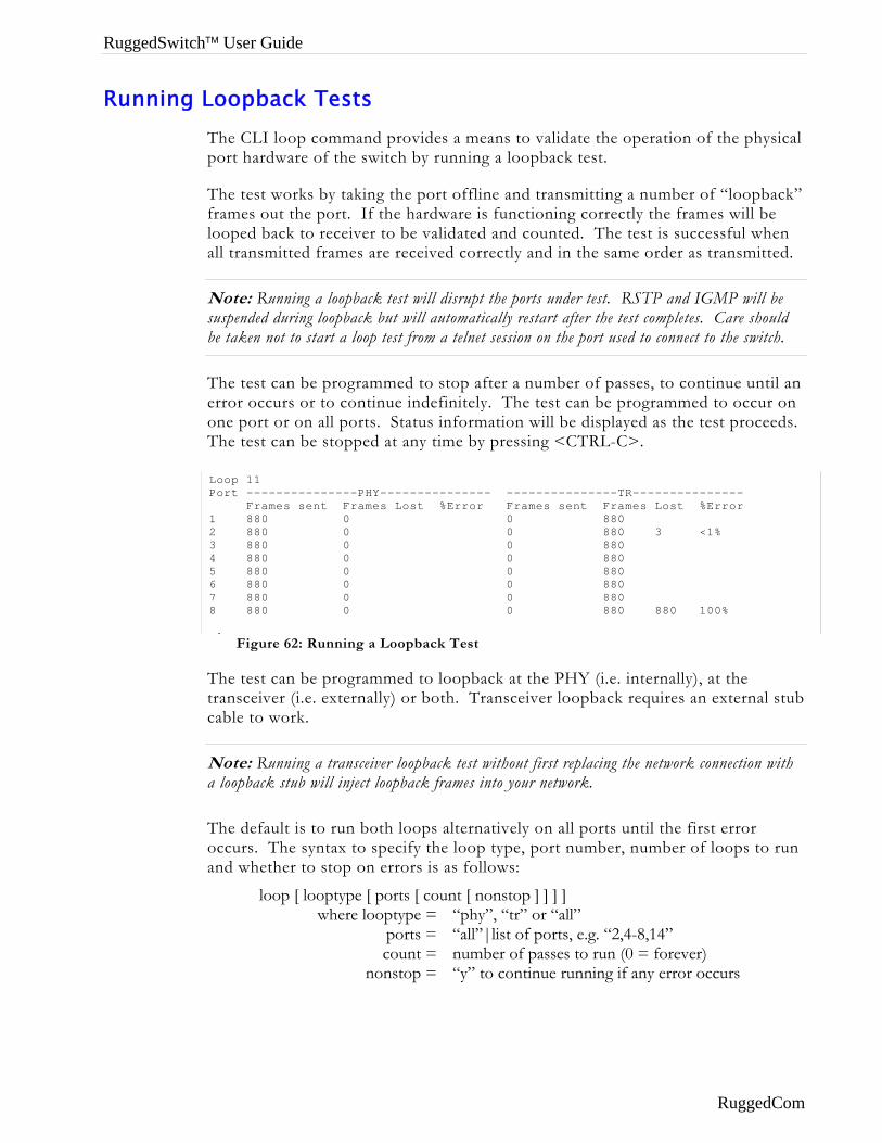
RuggedSwitch™ User Guide
Running Loopback Tests The CLI loop command provides a means to validate the operation of the physical port hardware of the switch by running a loopback test.
The test works by taking the port offline and transmitting a number of “loopback” frames out the port. If the hardware is functioning correctly the frames will be looped back to receiver to be validated and counted. The test is successful when all transmitted frames are received correctly and in the same order as transmitted.
Note: Running a loopback test will disrupt the ports under test. RSTP and IGMP will be suspended during loopback but will automatically restart after the test completes. Care should be taken not to start a loop test from a telnet session on the port used to connect to the switch.
The test can be programmed to stop after a number of passes, to continue until an error occurs or to continue indefinitely. The test can be programmed to occur on one port or on all ports. Status information will be displayed as the test proceeds. The test can be stopped at any time by pressing <CTRL-C>.
Ttc
Na
Toa
LP 12345678
Figure 62: Running a Loopback Test
oop 11 ort ---------------PHY--------------- ---------------TR--------------- Frames sent Frames Lost %Error Frames sent Frames Lost %Error 880 0 0 880 880 0 0 880 3 <1% 880 0 0 880 880 0 0 880 880 0 0 880 880 0 0 880 880 0 0 880 880 0 0 880 880 100%
l
he test can be programmed to loopback at the PHY (i.e. internally), at the ransceiver (i.e. externally) or both. Transceiver loopback requires an external stub able to work.
ote: Running a transceiver loopback test without first replacing the network connection with loopback stub will inject loopback frames into your network.
he default is to run both loops alternatively on all ports until the first error ccurs. The syntax to specify the loop type, port number, number of loops to run nd whether to stop on errors is as follows:
loop [ looptype [ ports [ count [ nonstop ] ] ] ] where looptype = “phy”, “tr” or “all”
ports = “all”|list of ports, e.g. “2,4-8,14” count = number of passes to run (0 = forever)
nonstop = “y” to continue running if any error occurs
RuggedCom

Chapter 10 - Using The CLI Shell
Pinging A Remote Device The ping command sends an ICMP echo request to a remotely connected device. For each reply received the round trip time is displayed.
The ping command can be used to ensure connectivity to the next connected device. The command “ping 192.168.0.1” will send a small number of pings to this device and display the results.
The ping command is a useful tool for testing commissioned links. The command also includes the ability to send a specific number of pings with specified time with which to wait for a response.
The specification of a large number of pings and a short response time can “flood” a link, stressing it more than a usual ping sequence. The command “ping 192.168.0.1 500 2” can be used to issue 500 pings each separated by 2 milliseconds to the next switch. If the link used is of high quality then no pings should be lost and the average round trip time should be small.
Note: The device to be pinged must support ICMP echo. Upon commencing the ping an ARP request for the MAC address of the device is issued. If the device is not on the same network as the switch the default gateway must be programmed.
RuggedCom 95
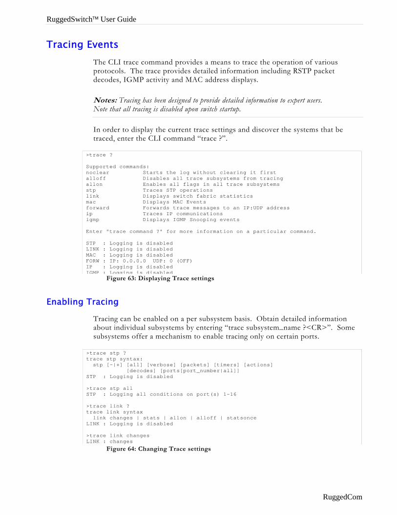
RuggedSwitch™ User Guide
Tracing Events The CLI trace command provides a means to trace the operation of various protocols. The trace provides detailed information including RSTP packet decodes, IGMP activity and MAC address displays.
Notes: Tracing has been designed to provide detailed information to expert users. Note that all tracing is disabled upon switch startup.
In order to display the current trace settings and discover the systems that be traced, enter the CLI command “trace ?”.
Enabling
> Snaaslmfii E SLMFII
>t S >S >t L >L
Figure 63: Displaying Trace settings
trace ?
upported commands: oclear Starts the log without clearing it first lloff Disables all trace subsystems from tracing llon Enables all flags in all trace subsystems tp Traces STP operations ink Displays switch fabric statistics ac Displays MAC Events orward Forwards trace messages to an IP:UDP address p Traces IP communications gmp Displays IGMP Snooping events
nter "trace command ?" for more information on a particular command.
TP : Logging is disabled INK : Logging is disabled AC : Logging is disabled ORW : IP: 0.0.0.0 UDP: 0 (OFF) P : Logging is disabled GMP : Logging is disabled
Tracing
Tracing can be enabled on a per subsystem basis. Obtain detailed information about individual subsystems by entering “trace subsystem_name ?<CR>”. Some subsystems offer a mechanism to enable tracing only on certain ports.
Figure 64: Changing Trace settings
trace stp ? race stp syntax: stp [-|+] [all] [verbose] [packets] [timers] [actions] [decodes] [ports[port_number|all]] TP : Logging is disabled
trace stp all TP : Logging all conditions on port(s) 1-16
trace link ? race link syntax link changes | stats | allon | alloff | statsonce INK : Logging is disabled
trace link changes INK : changes
RuggedCom
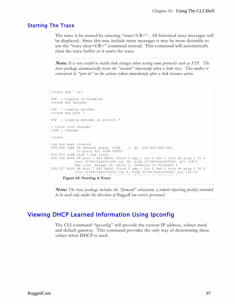
Chapter 10 - Using The CLI Shell
Starting The Trace
The trace is be started by entering “trace<CR>”. All historical trace messages will be displayed. Since this may include many messages it may be more desirable to use the “trace clear<CR>” command instead. This command will automatically clear the trace buffer as it starts the trace.
Note: It is very useful to enable link changes when testing some protocols such as STP. The trace package automatically resets the “seconds” timestamp when a link rises. This makes it convenient to “zero in” on the actions taken immediately after a link becomes active.
Figure 65: Starting A Trace
Note: The trace package includes the “forward” subsystem, a remote reporting facility intended to be used only under the direction of RuggedCom service personnel.
>trace stp - all STP : Logging is disabled >trace stp decodes STP : Logging decodes >trace stp port 7 STP : Logging decodes on port(s) 7 > trace link changes LINK : changes >trace Log has been cleared 009.445 IGMP TX General Query, VLAN 1, gr. 000.000.000.000, to ports ALL VLAN PORTS 010.543 LINK Link 7 has risen. 000.550 RSTP TX port 7 RST BPDU: TCack 0 agg 1 lrn 0 fwd 0 role DP prop 1 TC 0 root 32768/0adc001000 cst 38, brdg 32768/0adc005000, prt 128/7 age 2.00, maxage 20, hello 2, fwddelay 15 V1Length 0 000.557 RSTP RX port 7 RST BPDU: TCack 0 agg 1 lrn 0 fwd 0 role DP prop 1 TC 0 root 32768/0adc004000 cst 0, brdg 32768/0adc004000, prt 128/14
age 0 00 maxage 20 hello 2 fwddelay 15 V1Length 0
Viewing DHCP Learned Information Using Ipconfig The CLI command “ipconfig” will provide the current IP address, subnet mask and default gateway. This command provides the only way of determining these values when DHCP is used.
RuggedCom 97
RuggedSwitch™ User Guide
Executing Commands Remotely Through RSH The Unix/Dos Remote Shell Facility can be used at the workstation to cause the product to act upon commands as if they were entered at the CLI prompt. The syntax of the RSH command is usually of the form:
rsh ipadd –l password command_string where ipadd = The address or resolved name of the product
password = The password for the access level you wish to issue the command at
command_string = The command to execute
The access level selected must support the given command.
Any output from the command will be returned to the workstation submitting the command. Commands that start interactive dialogs (such as trace or loop) cannot be used.
Resetting The Switch The CLI command “reset” can be used to reset the switch.
RuggedCom
Chapter 11 – Upgrading Firmware And Managing Configurations
Chapter 11 – Upgrading Firmware And Managing Configurations
Introduction This chapter familiarizes the user with:
• Upgrading firmware using the XModem protocol and Trivial File Transfer Protocol (TFTP)
• Capturing and restoring the switch configuration using XModem and TFTP
• Using SQL commands to view/change configuration.
Upgrading Firmware You may be required to upgrade the switch firmware in order to take advantage of new features or bug fixes.
Your RuggedSwitch™ has two firmware components, the boot binary and the main application binary. In normal practice only the main application will have to be upgraded. Your RuggedCom representative will provide you with this file. It will be of the form RuggedSwitch_Main_v1.x.y.bin.
You may upgrade using either an XModem or TFTP protocol utility. If you will use XModem you upgrade from the RS232 port or through a Telnet session.
TFTP transfers may be performed in one of two ways. A TFTP client upon a Unix/Dos workstation can be used to contact the RuggedSwitch™ TFTP server. This method is very convenient, but will not provide control over who is allowed to upgrade the switch. Alternatively, the TFTP client in the RuggedSwitch™ CLI shell can be used to contact a Unix/Dos host supporting a TFTP server. You must set up a TFTP server on your network, but only admin level users can then perform upgrades.
Note: Security during file transfer by XModem and TFTP is established in the following ways. Transfers from the CLI shell XModem and TFTP clients are determined by the access level of the user. Downloads may only be performed by administrators while uploads may be performed by operators and administrators. TFTP transfers to the RuggedSwitch™ TFTP Server are controlled by the IP Services Configuration Menu, TFTP Server parameter.
RuggedCom 99
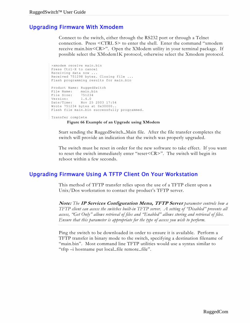
RuggedSwitch™ User Guide
Upgrading Firmware With Xmodem
Connect to the switch, either through the RS232 port or through a Telnet connection. Press <CTRL S> to enter the shell. Enter the command “xmodem receive main.bin<CR>”. Open the XModem utility in your terminal package. If possible select the XModem1K protocol, otherwise select the Xmodem protocol.
Modem
Upgradin
Figure 66 Example of an Upgrade using X
>xmodem receive main.bin Press Ctrl-X to cancel Receiving data now ... Received 751298 bytes. Closing file ... Flash programming results for main.bin Product Name: RuggedSwitch File Name: main.bin File Size: 751234 Version: 1.4.0 Date/Time: Nov 25 2003 17:54 Wrote 751234 bytes at 0x30000.. Flash file main.bin successfully programmed. Transfer complete
Start sending the RuggedSwitch_Main file. After the file transfer completes the switch will provide an indication that the switch was properly upgraded.
The switch must be reset in order for the new software to take effect. If you want to reset the switch immediately enter “reset<CR>”. The switch will begin its reboot within a few seconds.
g Firmware Using A TFTP Client On Your Workstation
This method of TFTP transfer relies upon the use of a TFTP client upon a Unix/Dos workstation to contact the product’s TFTP server.
Note: The IP Services Configuration Menu, TFTP Server parameter controls how a TFTP client can access the switches built-in TFTP server. A setting of “Disabled” prevents all access, “Get Only” allows retrieval of files and “Enabled” allows storing and retrieval of files. Ensure that this parameter is appropriate for the type of access you wish to perform.
Ping the switch to be downloaded in order to ensure it is available. Perform a TFTP transfer in binary mode to the switch, specifying a destination filename of “main.bin”. Most command line TFTP utilities would use a syntax similar to “tftp –i hostname put local_file remote_file”.
RuggedCom
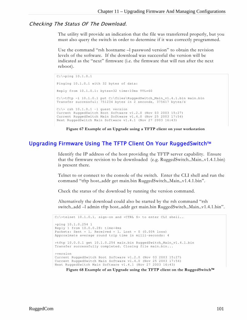
Chapter 11 – Upgrading Firmware And Managing Configurations
Checking The Status OF The Download.
The utility will provide an indication that the file was transferred properly, but you must also query the switch in order to determine if it was correctly programmed.
Use the command “rsh hostname –l password version” to obtain the revision levels of the software. If the download was successful the version will be indicated as the “next” firmware (i.e. the firmware that will run after the next reboot).
Figure 67 Example of an Upgrade using a TFTP client on your workstation
Upgrading Firmware Using The TFTP Client On Your RuggedSwitch™
Identify the IP address of the host providing the TFTP server capability. Ensure that the firmware revision to be downloaded (e.g. RuggedSwitch_Main_v1.4.1.bin) is present there.
Telnet to or connect to the console of the switch. Enter the CLI shell and run the command “tftp host_addr get main.bin RuggedSwitch_Main_v1.4.1.bin”.
Check the status of the download by running the version command.
Alternatively the download could also be started by the rsh command “rsh switch_add –l admin tftp host_addr get main.bin RuggedSwitch_Main_v1.4.1.bin”.
Figure 68 Example of an Upgrade using the TFTP client on the RuggedSwitch™
C:\>ping 10.1.0.1 Pinging 10.1.0.1 with 32 bytes of data: Reply from 10.1.0.1: bytes=32 time<10ms TTL=60 C:\>tftp -i 10.1.0.1 put C:\files\RuggedSwitch_Main_v1.4.1.bin main.bin Transfer successful: 751234 bytes in 2 seconds, 375617 bytes/s C:\> rsh 10.1.0.1 –l guest version Current RuggedSwitch Boot Software v1.2.0 (Nov 03 2003 15:27) Current RuggedSwitch Main Software v1.4.0 (Nov 25 2003 17:54) Next RuggedSwitch Main Software v1.4.1 (Nov 27 2003 16:43)
C:\>telnet 10.1.0.1, sign-on and <CTRL S> to enter CLI shell.. >ping 10.1.0.254 1 Reply 1 from 10.0.0.28: time<4ms Packets: Sent = 1, Received = 1, Lost = 0 (0.00% loss) Approximate average round trip time in milli-seconds: 4 >tftp 10.0.0.1 get 10.1.0.254 main.bin RuggedSwitch_Main_v1.4.1.bin Transfer successfully completed. Closing file main.bin... >version Current RuggedSwitch Boot Software v1.2.0 (Nov 03 2003 15:27) Current RuggedSwitch Main Software v1.4.0 (Nov 25 2003 17:54) Next RuggedSwitch Main Software v1.4.1 (Nov 27 2003 16:43)
RuggedCom 101
RuggedSwitch™ User Guide
Capturing Configurations
The RuggedSwitch™ provides a means to capture the configuration of the switch in an ASCII formatted text file.
The same file can be downloaded to the switch at a later date in order to restore the switch to its previous configuration.
Different versions of configuration file can be compared using an ASCII text difference tool, in order to pinpoint configuration changes.
Capturing Configurations With XModem
Connect to the switch, either through the RS232 port or through a Telnet connection. Press <CTRL S> to enter the shell. Enter the command “xmodem send config.csv<CR>”. Open the XModem utility in your terminal package and start an XModem receive to the desired local filename. Open the file to verify that it contains the appropriate configuration.
Note: You may wish to include date and node address/name information in the local filename.
Capturing Configurations With TFTP
Ping the switch to be uploaded in order to ensure it is available. Perform a TFTP transfer from the switch, specifying a remote filename of “config.csv” and a desired local filename. Most command line TFTP utilities would use syntax similar to “tftp hostname get config.csv local_file”.
Alternatively, sign-on to the product and use the CLI shell’s tftp command to send the configuration file to your TFTP server.
Open the file to verify that contains the appropriate configuration.
RuggedCom
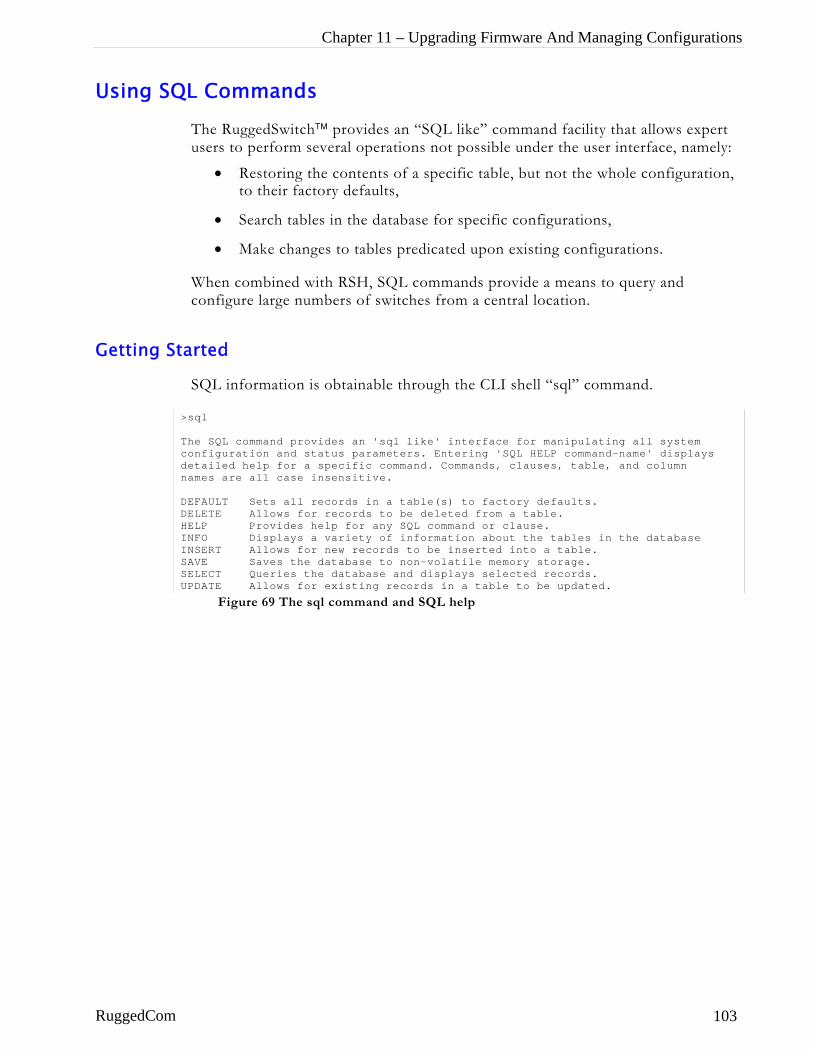
Chapter 11 – Upgrading Firmware And Managing Configurations
Using SQL Commands
The RuggedSwitch™ provides an “SQL like” command facility that allows expert users to perform several operations not possible under the user interface, namely:
• Restoring the contents of a specific table, but not the whole configuration, to their factory defaults,
• Search tables in the database for specific configurations,
• Make changes to tables predicated upon existing configurations.
When combined with RSH, SQL commands provide a means to query and configure large numbers of switches from a central location.
Getting Started
SQL information is obtainable through the CLI shell “sql” command.
> Tcdn DDHIISSU
RuggedCom
Figure 69 The sql command and SQL help
sql
he SQL command provides an 'sql like' interface for manipulating all system onfiguration and status parameters. Entering 'SQL HELP command-name' displays etailed help for a specific command. Commands, clauses, table, and column ames are all case insensitive.
EFAULT Sets all records in a table(s) to factory defaults. ELETE Allows for records to be deleted from a table. ELP Provides help for any SQL command or clause. NFO Displays a variety of information about the tables in the database NSERT Allows for new records to be inserted into a table. AVE Saves the database to non-volatile memory storage. ELECT Queries the database and displays selected records. PDATE Allows for existing records in a table to be updated.
103
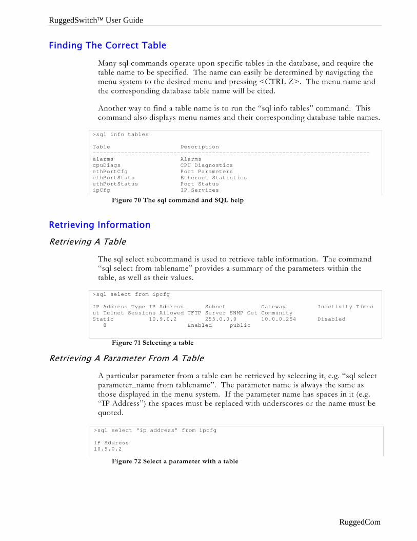
RuggedSwitch™ User Guide
Finding The Correct Table
Many sql commands operate upon specific tables in the database, and require the table name to be specified. The name can easily be determined by navigating the menu system to the desired menu and pressing <CTRL Z>. The menu name and the corresponding database table name will be cited.
Another way to find a table name is to run the “sql info tables” command. This command also displays menu names and their corresponding database table names.
Figure 70 The sql command and SQL help
Retrieving Information
Retrieving A Table
The sql select subcommand is used to retrieve table information. The command “sql select from tablename” provides a summary of the parameters within the table, as well as their values.
Figure 71 Selecting a table
Retrieving A Parameter From A Table
A particular parameter from a table can be retrieved by selecting it, e.g. “sql select parameter_name from tablename”. The parameter name is always the same as those displayed in the menu system. If the parameter name has spaces in it (e.g. “IP Address”) the spaces must be replaced with underscores or the name must be quoted.
Figure 72 Select a parameter with a table
>sql info tables Table Description ------------------------------------------------------------------------------- alarms Alarms cpuDiags CPU Diagnostics ethPortCfg Port Parameters ethPortStats Ethernet Statistics ethPortStatus Port Status ipCfg IP Services
>sql select from ipcfg IP Address Type IP Address Subnet Gateway Inactivity Timeo ut Telnet Sessions Allowed TFTP Server SNMP Get Community Static 10.9.0.2 255.0.0.0 10.0.0.254 Disabled 8 Enabled public
>sql select “ip address” from ipcfg IP Address 10.9.0.2
RuggedCom
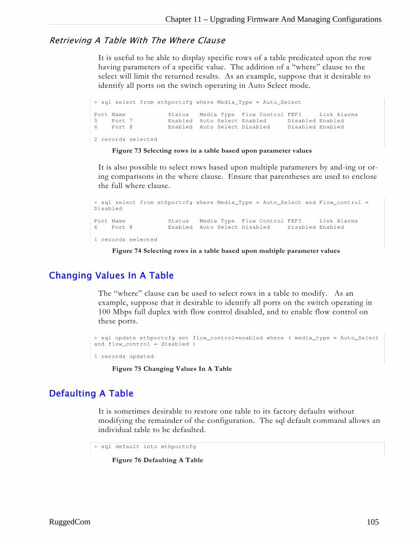
Chapter 11 – Upgrading Firmware And Managing Configurations
Retrieving A Table With The Where Clause
It is useful to be able to display specific rows of a table predicated upon the row having parameters of a specific value. The addition of a “where” clause to the select will limit the returned results. As an example, suppose that it desirable to identify all ports on the switch operating in Auto Select mode.
Changing
Defaulting
RuggedCom
> sql select from ethportcfg where Media_Type = Auto_Select Port Name Status Media Type Flow Control FEFI Link Alarms 5 Port 7 Enabled Auto Select Enabled Disabled Enabled 6 Port 8 Enabled Auto Select Disabled Disabled Enabled 2 records selected
Figure 73 Selecting rows in a table based upon parameter values
It is also possible to select rows based upon multiple parameters by and-ing or or-ing comparisons in the where clause. Ensure that parentheses are used to enclose the full where clause.
> sql select from ethportcfg where Media_Type = Auto_Select and Flow_control = Disabled
Figure 74 Selecting rows in a table based upon multiple parameter values
Port Name Status Media Type Flow Control FEFI Link Alarms 6 Port 8 Enabled Auto Select Disabled Disabled Enabled 1 records selected
Values In A Table
The “where” clause can be used to select rows in a table to modify. As an example, suppose that it desirable to identify all ports on the switch operating in 100 Mbps full duplex with flow control disabled, and to enable flow control on these ports.
> sql update ethportcfg set flow_control=enabled where ( media_type = Auto_Select and flow_control = disabled )
Figure 75 Changing Values In A Table
1 records updated
A Table
It is sometimes desirable to restore one table to its factory defaults without modifying the remainder of the configuration. The sql default command allows an individual table to be defaulted.
le
> sql default into ethportcfg
Figure 76 Defaulting A Tab
105
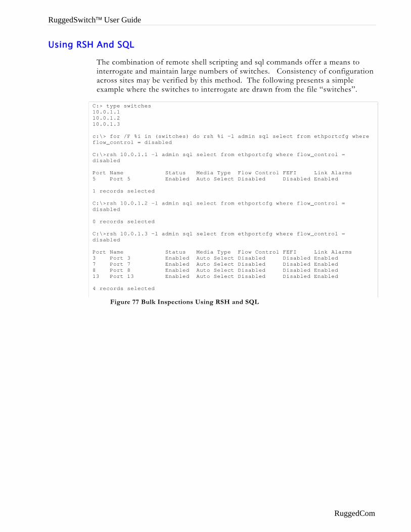
RuggedSwitch™ User Guide
Using RSH And SQL
The combination of remote shell scripting and sql commands offer a means to interrogate and maintain large numbers of switches. Consistency of configuration across sites may be verified by this method. The following presents a simple example where the switches to interrogate are drawn from the file “switches”.
Figure 77 Bulk Inspections Using RSH and SQL
C:> type switches 10.0.1.1 10.0.1.2 10.0.1.3 c:\> for /F %i in (switches) do rsh %i -l admin sql select from ethportcfg where flow_control = disabled C:\>rsh 10.0.1.1 -l admin sql select from ethportcfg where flow_control = disabled Port Name Status Media Type Flow Control FEFI Link Alarms 5 Port 5 Enabled Auto Select Disabled Disabled Enabled 1 records selected C:\>rsh 10.0.1.2 -l admin sql select from ethportcfg where flow_control = disabled 0 records selected C:\>rsh 10.0.1.3 -l admin sql select from ethportcfg where flow_control = disabled Port Name Status Media Type Flow Control FEFI Link Alarms 3 Port 3 Enabled Auto Select Disabled Disabled Enabled 7 Port 7 Enabled Auto Select Disabled Disabled Enabled 8 Port 8 Enabled Auto Select Disabled Disabled Enabled 13 Port 13 Enabled Auto Select Disabled Disabled Enabled 4 records selected
RuggedCom
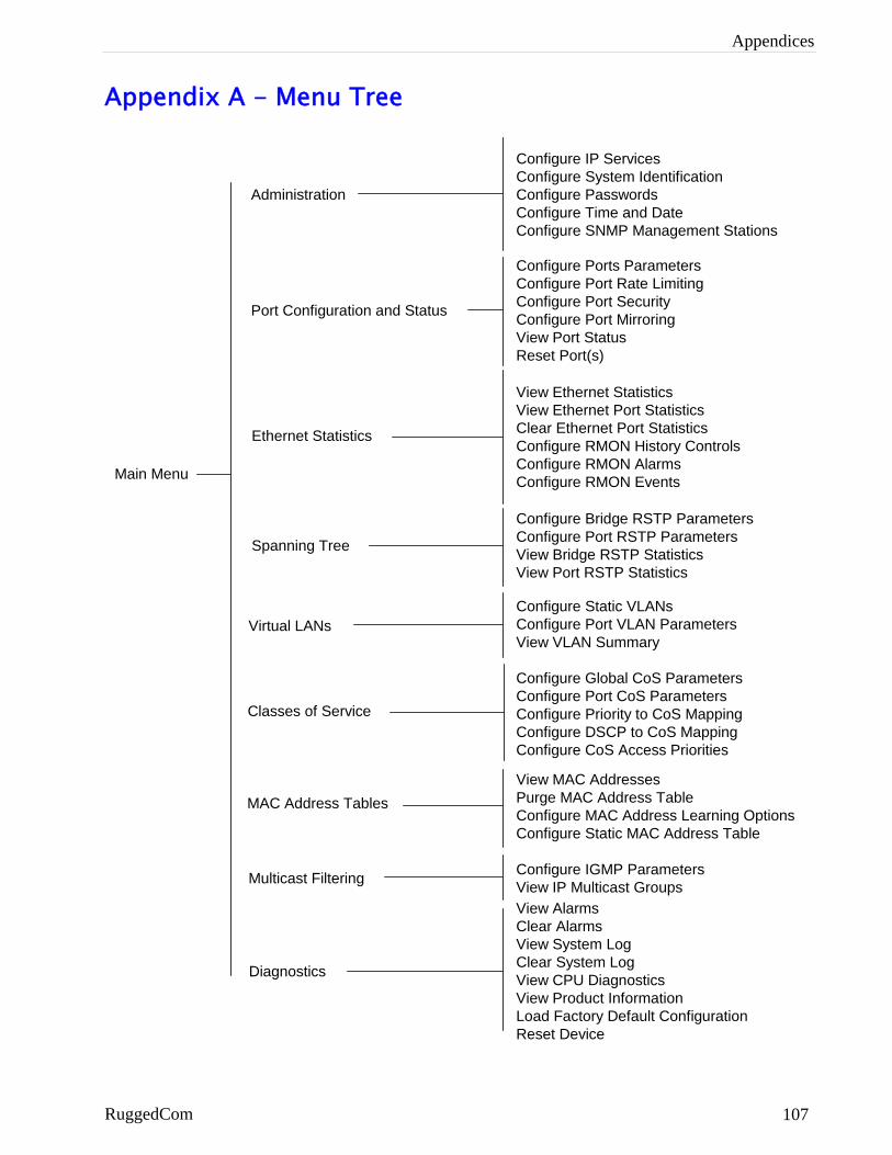
Appendices
Appendix A - Menu Tree
Main Menu
Administration
Configure IP ServicesConfigure System IdentificationConfigure PasswordsConfigure Time and DateConfigure SNMP Management Stations
Configure Ports ParametersConfigure Port Rate LimitingConfigure Port SecurityConfigure Port MirroringView Port StatusReset Port(s)
Port Configuration and Status
Ethernet Statistics
Spanning Tree
View Ethernet StatisticsView Ethernet Port StatisticsClear Ethernet Port StatisticsConfigure RMON History ControlsConfigure RMON AlarmsConfigure RMON Events
Configure Bridge RSTP ParametersConfigure Port RSTP ParametersView Bridge RSTP StatisticsView Port RSTP Statistics
Virtual LANs
Diagnostics
Configure Static VLANsConfigure Port VLAN ParametersView VLAN Summary
View AlarmsClear AlarmsView System LogClear System LogView CPU DiagnosticsView Product InformationLoad Factory Default ConfigurationReset Device
Classes of Service
Configure Global CoS ParametersConfigure Port CoS ParametersConfigure Priority to CoS MappingConfigure DSCP to CoS MappingConfigure CoS Access Priorities
MAC Address TablesView MAC AddressesPurge MAC Address TableConfigure MAC Address Learning OptionsConfigure Static MAC Address Table
Multicast Filtering Configure IGMP ParametersView IP Multicast Groups
RuggedCom 107
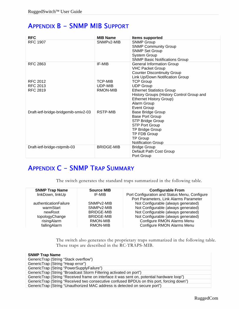
RuggedSwitch™ User Guide
APPENDIX B - SNMP MIB SUPPORT RFC MIB Name Items supported RFC 1907 SNMPv2-MIB SNMP Group
SNMP Community Group SNMP Set Group System Group SNMP Basic Notifications Group
RFC 2863 IF-MIB General Information Group VHC Packet Group Counter Discontinuity Group Link Up/Down Notification Group
RFC 2012 TCP-MIB TCP Group RFC 2013 UDP-MIB UDP Group RFC 2819 RMON-MIB Ethernet Statistics Group
History Groups (History Control Group and Ethernet History Group) Alarm Group Event Group
Draft-ietf-bridge-bridgemib-smiv2-03 RSTP-MIB Base Bridge Group Base Port Group STP Bridge Group STP Port Group TP Bridge Group TP FDB Group TP Group Notification Group
Draft-ietf-bridge-rstpmib-03 BRIDGE-MIB Bridge Group Default Path Cost Group Port Group
APPENDIX C – SNMP TRAP SUMMARY The switch generates the standard traps summarized in the following table.
SNMP Trap Name Source MIB Configurable From linkDown, linkUp IF-MIB Port Configuration and Status Menu, Configure
Port Parameters, Link Alarms Parameter authenticationFailure SNMPv2-MIB Not Configurable (always generated)
warmStart SNMPv2-MIB Not Configurable (always generated) newRoot BRIDGE-MIB Not Configurable (always generated)
topologyChange BRIDGE-MIB Not Configurable (always generated) risingAlarm RMON-MIB Configure RMON Alarms Menu fallingAlarm RMON-MIB Configure RMON Alarms Menu
The switch also generates the proprietary traps summarized in the following table. These traps are described in the RC-TRAPS-MIB.
SNMP Trap Name GenericTrap (String “Stack overflow”) GenericTrap (String “Heap error”) GenericTrap (String “PowerSupplyFailure”) GenericTrap (String “Broadcast Storm Filtering activated on port”) GenericTrap (String “Received frame on interface it was sent on, potential hardware loop”) GenericTrap (String “Received two consecutive confused BPDUs on this port, forcing down”) GenericTrap (String “Unauthorized MAC address is detected on secure port”)
RuggedCom
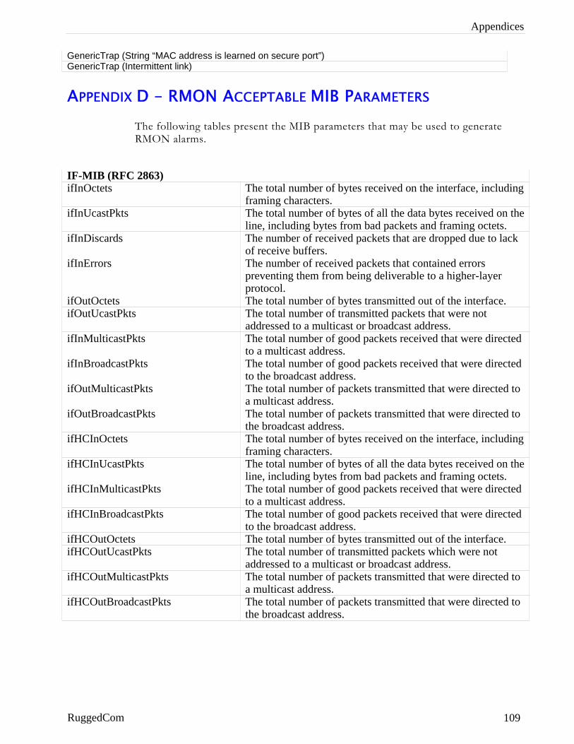
Appendices
GenericTrap (String “MAC address is learned on secure port”) GenericTrap (Intermittent link)
APPENDIX D – RMON ACCEPTABLE MIB PARAMETERS The following tables present the MIB parameters that may be used to generate RMON alarms.
IF-MIB (RFC 2863) ifInOctets The total number of bytes received on the interface, including
framing characters. ifInUcastPkts The total number of bytes of all the data bytes received on the
line, including bytes from bad packets and framing octets. ifInDiscards The number of received packets that are dropped due to lack
of receive buffers. ifInErrors The number of received packets that contained errors
preventing them from being deliverable to a higher-layer protocol.
ifOutOctets The total number of bytes transmitted out of the interface. ifOutUcastPkts The total number of transmitted packets that were not
addressed to a multicast or broadcast address. ifInMulticastPkts The total number of good packets received that were directed
to a multicast address. ifInBroadcastPkts The total number of good packets received that were directed
to the broadcast address. ifOutMulticastPkts The total number of packets transmitted that were directed to
a multicast address. ifOutBroadcastPkts The total number of packets transmitted that were directed to
the broadcast address. ifHCInOctets The total number of bytes received on the interface, including
framing characters. ifHCInUcastPkts The total number of bytes of all the data bytes received on the
line, including bytes from bad packets and framing octets. ifHCInMulticastPkts The total number of good packets received that were directed
to a multicast address. ifHCInBroadcastPkts The total number of good packets received that were directed
to the broadcast address. ifHCOutOctets The total number of bytes transmitted out of the interface. ifHCOutUcastPkts The total number of transmitted packets which were not
addressed to a multicast or broadcast address. ifHCOutMulticastPkts The total number of packets transmitted that were directed to
a multicast address. ifHCOutBroadcastPkts The total number of packets transmitted that were directed to
the broadcast address.
RuggedCom 109
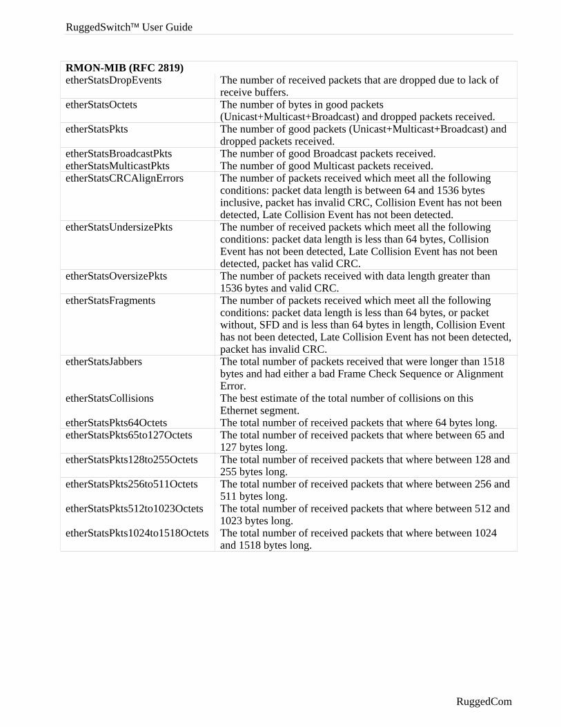
RuggedSwitch™ User Guide
RMON-MIB (RFC 2819) etherStatsDropEvents The number of received packets that are dropped due to lack of
receive buffers. etherStatsOctets The number of bytes in good packets
(Unicast+Multicast+Broadcast) and dropped packets received. etherStatsPkts The number of good packets (Unicast+Multicast+Broadcast) and
dropped packets received. etherStatsBroadcastPkts The number of good Broadcast packets received. etherStatsMulticastPkts The number of good Multicast packets received. etherStatsCRCAlignErrors The number of packets received which meet all the following
conditions: packet data length is between 64 and 1536 bytes inclusive, packet has invalid CRC, Collision Event has not been detected, Late Collision Event has not been detected.
etherStatsUndersizePkts The number of received packets which meet all the following conditions: packet data length is less than 64 bytes, Collision Event has not been detected, Late Collision Event has not been detected, packet has valid CRC.
etherStatsOversizePkts The number of packets received with data length greater than 1536 bytes and valid CRC.
etherStatsFragments The number of packets received which meet all the following conditions: packet data length is less than 64 bytes, or packet without, SFD and is less than 64 bytes in length, Collision Event has not been detected, Late Collision Event has not been detected, packet has invalid CRC.
etherStatsJabbers The total number of packets received that were longer than 1518 bytes and had either a bad Frame Check Sequence or Alignment Error.
etherStatsCollisions The best estimate of the total number of collisions on this Ethernet segment.
etherStatsPkts64Octets The total number of received packets that where 64 bytes long. etherStatsPkts65to127Octets The total number of received packets that where between 65 and
127 bytes long. etherStatsPkts128to255Octets The total number of received packets that where between 128 and
255 bytes long. etherStatsPkts256to511Octets The total number of received packets that where between 256 and
511 bytes long. etherStatsPkts512to1023Octets The total number of received packets that where between 512 and
1023 bytes long. etherStatsPkts1024to1518Octets The total number of received packets that where between 1024
and 1518 bytes long.
RuggedCom
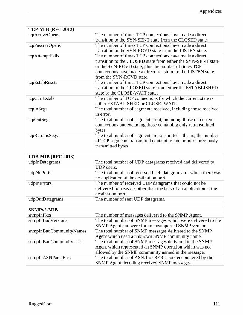
Appendices
TCP-MIB (RFC 2012) tcpActiveOpens The number of times TCP connections have made a direct
transition to the SYN-SENT state from the CLOSED state. tcpPassiveOpens The number of times TCP connections have made a direct
transition to the SYN-RCVD state from the LISTEN state. tcpAttemptFails The number of times TCP connections have made a direct
transition to the CLOSED state from either the SYN-SENT state or the SYN-RCVD state, plus the number of times TCP connections have made a direct transition to the LISTEN state from the SYN-RCVD state.
tcpEstabResets The number of times TCP connections have made a direct transition to the CLOSED state from either the ESTABLISHED state or the CLOSE-WAIT state.
tcpCurrEstab The number of TCP connections for which the current state is either ESTABLISHED or CLOSE- WAIT.
tcpInSegs The total number of segments received, including those received in error.
tcpOutSegs The total number of segments sent, including those on current connections but excluding those containing only retransmitted bytes.
tcpRetransSegs The total number of segments retransmitted - that is, the number of TCP segments transmitted containing one or more previously transmitted bytes.
UDB-MIB (RFC 2013) udpInDatagrams The total number of UDP datagrams received and delivered to
UDP users. udpNoPorts The total number of received UDP datagrams for which there was
no application at the destination port. udpInErrors The number of received UDP datagrams that could not be
delivered for reasons other than the lack of an application at the destination port.
udpOutDatagrams The number of sent UDP datagrams. SNMPv2-MIB snmpInPkts The number of messages delivered to the SNMP Agent. snmpInBadVersions The total number of SNMP messages which were delivered to the
SNMP Agent and were for an unsupported SNMP version. snmpInBadCommunityNames The total number of SNMP messages delivered to the SNMP
Agent which used a unknown SNMP community name. snmpInBadCommunityUses The total number of SNMP messages delivered to the SNMP
Agent which represented an SNMP operation which was not allowed by the SNMP community named in the message.
snmpInASNParseErrs The total number of ASN.1 or BER errors encountered by the SNMP Agent decoding received SNMP messages.
RuggedCom 111

RuggedSwitch™ User Guide
BRIDGE-MIB (draft-ietf-bridge-bridgemib-smiv2-03) dot1dBasePortDelayExceededDiscards The number of frames discarded by this port due to
excessive transit delay through the bridge. dot1dBasePortMtuExceededDiscards The number of frames discarded by this port due to an
excessive size. dot1dTpPortInFrames The number of frames that have been received by this
port from its segment. dot1dTpPortOutFrames The number of frames that have been transmitted by this
port to its segment.
RuggedCom
Index
INDEX Alarms Indicator 3 Features, Port 18 Features, VLAN 31 Gateway Address, Configuring 6 Loss-of-Link Management 21 MAC Table, Configuring 13 Password, Default 1 RS232 port 1 RSTP Ring Backbone Configurations 59 RSTP Structured Wiring Configurations 58 RSTP, Edge ports 55 VLAN, Management 33 Aging Time, Configuring 15 Alarms, Active 89 Alarms, Clearing 92 Alarms, Critical Failure Relay 91 Alarms, Level 90 Alarms, Passive 90 Alarms, Using 89 Alarms, Viewing 91 Broadcast Rate Limiting 20 Broadcast Rate Limiting, Configuring 26 CLI Shell 3 CLI Shell, CLEARLOGS command 114 CLI Shell, Command Summary 113 CLI Shell, DIR command 114 CLI Shell, Entering And Leaving 112 CLI Shell, LOOP command 115 CLI Shell, PING command 116 CLI Shell, RESET command 120 CLI Shell, TRACE command 117 CLI Shell, TYPE command 114 Configurations, Capturing 125 CoS Configuration 46 CoS Priority Weighting 47 CoS, High Access Priority 49 CoS, Inspecting TOS DSCP 48 CoS, Normal Access Priority 49 CoS, Port Default 47 DHCP, Configuring 5 Features, CoS 44 Features, IGMP 75 Features, RSTP 50 Features,MAC Management 13 FEFI, Configuring 25 Firmware, Upgrading 121 Firmware, Versions 95 Flow Control, Configuring 25 IGMP Active and Passive Mode 78
RuggedCom 113
RuggedSwitch™ User Guide
IGMP Configuration 82 IGMP Consumers and Producers 77 IGMP general membership queries 77 IGMP group specific membership queries 78 IGMP leave group message 78 IGMP membership reports 77 IGMP Operation 77 IGMP Query Interval, Configuring 83 IGMP Router Ports, Configuring 83 IGMP Snooping 34 IGMP, Statistics 83 IGMP, Troubleshooting 86 Inactivity Timeout, Configuring 6 IP Address, Configuring 6 Layer 3 switches, Using 32 Link Alarms, Configuring 25 Load Factory Default Configuration 96 MAC Addresses, Static, Configuring 15 MAC Addresses,Viewing 14 MAC Table, Purging 15 Media Type, Configuring 24 Menu Tree 131 Menu, Administration 5 Menu, Bridge RSTP Parameters 62 Menu, Configured and Learned VLANs 42 Menu, CoS Priorities 46 Menu, CPU Dignostics 93 Menu, Ethernet Port Statistics 98 Menu, Ethernet Statistics 97, 98 Menu, IGMP Parameters 82 Menu, IP Multicast Groups Menu 83 Menu, IP Services Configuration 5 Menu, MAC Address Tables 13 Menu, MAC Learning Options 15 Menu, Multicast Filtering 82 Menu, Port Configuration 24 Menu, Port Mirroring 28 Menu, Port Rate Limiting 25 Menu, Port RSTP Parameters 64 Menu, Port RSTP Statistics 68 Menu, Port Security 26 Menu, Port Status 29 Menu, Port VLAN Parameters 39 Menu, RMON Alarms 106 Menu, RMON Events Log Table 109 Menu, RMON Events Table 108 Menu, RMON History Control Table 102 Menu, RMON History Samples Table 103 Menu, RSTP Statistics 66 Menu, SNMP Management Stations 10 Menu, Spanning Tree Menu 62
114 RuggedCom
Index
Menu, Time and Date 8 Menu, Virtual LANs 37 Multicast Filtering 75 NTP Server Address, Configuring 9 NTP Update Period, Configuring 9 Password, Configuring 8 Port Mirroring 22 Port Mirroring, Configuring 28 Port Rate Limiting 25 Port Security 19, 26 Port Statistics, Viewing 98 Ports, Configuring 23 Ports, Resetting 29 Ports, Troubleshooting 30 Product Identification 95 Resetting, Device 96 RMON 100 RMON, Alarms And Events 104 RMON, Historical Statistics 101 RMON, Troubleshooting 111 RSH, Using 120 RSTP Bridge Priority, Configuring 62 RSTP Configuration 61 RSTP Cost Style, Configuring 63 RSTP Cost, Configuring 65 RSTP Edge Port, Configuring 65 RSTP Forward delay,Configuring 63 RSTP Hello Time, Configuring 63 RSTP Max Age Time, Configuring 63 RSTP Point to Point, Configuring 65 RSTP Port Enable, Configuring 64 RSTP Port Priority, Configuring 64 RSTP State, Configuring 62 RSTP Transmit Count, Configuring 63 RSTP Version Support, Configuring 62 RSTP, Bridge Diameter 56 RSTP, Operation 51 RSTP, Path Costs 55 RSTP, Point To Point Links 55 RSTP, Troubleshooting 71 RuggedSwitch( User Interface 1 SNMP Community String, Configuring 10 SNMP Get Community ,Configuring 7 SNMP Management Station Address, Configuring 10 SNMP Set Access, Configuring 10 SNMP Trap Sending, Configuring 11 SNMP, Mibs supported 132 SNMP, Trap Summary 132 SQL Commands, Using 127 SQL, “From” Clause 128 SQL, “Where” Clause 129
RuggedCom 115
RuggedSwitch™ User Guide
SQL, Default Command 130 SQL, Info Command 128 SQL, Select Command 128 SQL, Update Command 129 Statistics 66 Subnet, Configuring 6 System Identification, Configuring 8 System Log, Clearing 95 System Log, Viewing 95 Telnet Sessions, Configuring 6 TFTP Client, Upgrading Firmware With 124 TFTP Server ,Configuring 7 TFTP Server, Upgrading Firmware With 122 Time Zone, Configuring 9 Troubleshooting, Administration Settings 12 VLAN Configuration 36 VLAN Forbidden Ports, Configuring 38 VLAN Ranges & Default Settings 36 VLAN Tagging 32 VLAN Untagged Edge Port 40 VLAN, Native 32 VLANs, Edge Type 40 VLANs, Static, Configuring 37 VLANs, Trunk Type 40 VLANs,Troubleshooting 43 XModem, Upgrading Firware With 122
116 RuggedCom