Embed Size (px)
Citation preview

Volume 17.1 www.lannerinc.com
Intelligent TransportationRugged Platforms for Vehicles and Railway Computing
Singel 3 | B-2550 Kontich | Belgium | Tel. +32 (0)3 458 30 33 | [email protected] | www.alcom.be
Rivium 1e straat 52 | 2909 LE Capelle aan den Ijssel | The Netherlands | Tel. +31 (0)10 288 25 00 | [email protected] | www.alcom.nl
V. 7/17

2 www.lannerinc.com

www.lannerinc.com 3
Spencer ChouSenior Director, ITS BU
Innovating Transportation Solutions for a Connected World
Over the past ten years, Lanner has dedicated itself in supplying the state-of-
the-art hardware solutions for IoT applications and millions of Lanner hardware
platforms have been deployed worldwide. Strengthening this momentum,
Lanner is expanding its technological fields by innovating transportation
solutions for a connected world.
Built on our already established expertise and reliability in our vehicle
computing systems, including fleet management, in-vehicle surveillance and
infotainment, Lanner has founded its Intelligent Transportation Solution
Business Unit, a newly established division dedicating in rolling stock and rail
gateway systems. These systems will deliver robust operability to be deployed
for train, high-speed rail, MRT (Mass Rapid Transit), and other public transit
applications.
Lanner has rich expertise and experience through customization services for
our clients in China, Europe, North America and Asia. We focus on developing
intelligent platforms that can help our clients reduce their development efforts
and cost. Our sole mission is to deliver a wide selection of platforms and
gateways to meet your application demands.

4 www.lannerinc.com
Contents
Who is Lanner? ...................................................................... 4
Solution Overview ................................................................... 6
Feature Highlights ................................................................... 8
Vehicle Computers Comparison ..............................................12
Rolling Stock Computers Comparison .....................................17
Application Stories ..................................................................18
Global Manufacturing Capabilities
Taipei, Taiwan
• Area 30,000 m²
• 3 x SMT, DIP and assembly lines
• Production capacity: 30,000 system units/month
Beijing and Dongguang, China
• Area 15,200 m²
• 5 x Assembly lines
• Production capacity: 8,000 system units/month
Service Capabilities
• Custom design and production in board,
chassis and system
• High mix low volume manufacturing
• Quality assurance services
• Global order fulfillment services
Certifications
• ISO 9001:2008
• ISO 14001:2004
• ISO 28000:2007
• QC 080000:2012
• OHSAS 18001:2007
• TL 9000:R5.5
Who is Lanner?
Lanner Electronics Inc. (TAIEX 6245) is a world-leading hardware provider in design, engineering,
and manufacturing services for advanced network appliances and rugged industrial computers.
With 30-year experiences, Lanner provides reliable and cost-effective computing platforms
with high quality and performance. Today, Lanner has a large and dynamic manpower of
over 900 well-experienced employees worldwide with the headquarters in Taipei, Taiwan and
subsidiaries in the US, Canada, and China.
www.lannerinc.com 5
Why Lanner?
Lanner designs and manufactures a wide range of embedded computing systems
for diversified applications. Our vehicle computers feature compact form factor,
ruggedness, shock/vibration resistance, wireless connectivity and rich I/O connectors.
We are committed to bringing reliability and high-performance intelligent transportation
systems to meet today’s strict demands for IoT applications.
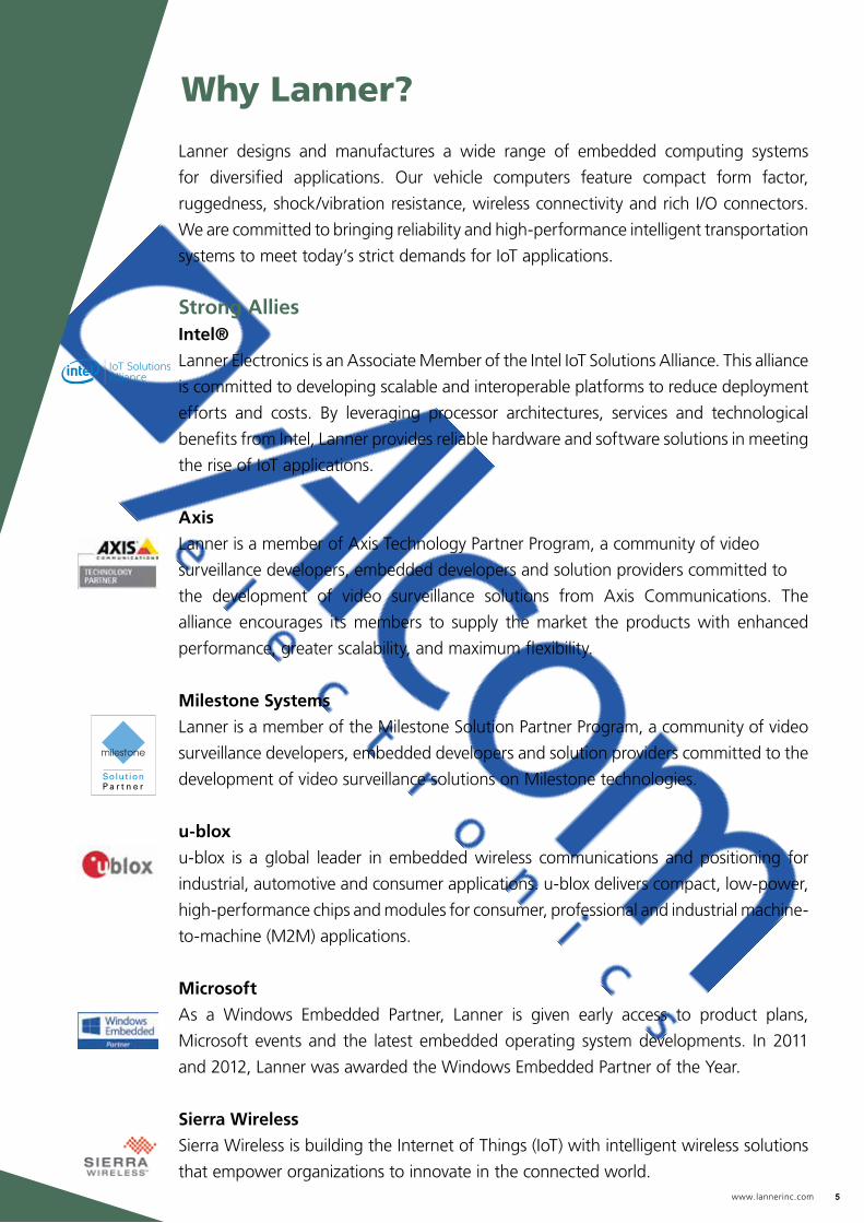
Strong AlliesIntel®
Lanner Electronics is an Associate Member of the Intel IoT Solutions Alliance. This alliance
is committed to developing scalable and interoperable platforms to reduce deployment
efforts and costs. By leveraging processor architectures, services and technological
benefits from Intel, Lanner provides reliable hardware and software solutions in meeting
the rise of IoT applications.
Axis
Lanner is a member of Axis Technology Partner Program, a community of video
surveillance developers, embedded developers and solution providers committed to
the development of video surveillance solutions from Axis Communications. The
alliance encourages its members to supply the market the products with enhanced
performance, greater scalability, and maximum flexibility.
Milestone Systems
Lanner is a member of the Milestone Solution Partner Program, a community of video
surveillance developers, embedded developers and solution providers committed to the
development of video surveillance solutions on Milestone technologies.
u-blox
u-blox is a global leader in embedded wireless communications and positioning for
industrial, automotive and consumer applications. u-blox delivers compact, low-power,
high-performance chips and modules for consumer, professional and industrial machine-
to-machine (M2M) applications.
Microsoft
As a Windows Embedded Partner, Lanner is given early access to product plans,
Microsoft events and the latest embedded operating system developments. In 2011
and 2012, Lanner was awarded the Windows Embedded Partner of the Year.
Sierra Wireless
Sierra Wireless is building the Internet of Things (IoT) with intelligent wireless solutions
that empower organizations to innovate in the connected world.
Solution P a r t n e r

6 www.lannerinc.com
Solution Overview
Taxi Fleet Management
Driver Behavior Management
e-Bus
Law Enforcement, see page 20
MRT Surveillance

www.lannerinc.com 7
Law Enforcement, see page 20
Ambulance Communication, see page 19
Rolling Stock Communication, see page 21
Waste Management
Fleet Management, see page 18

8 www.lannerinc.com
Vehicle & Rolling Stock Box PCs
Power Ignition ControlA user-friendly Power Ignition Control is
programmed to start and shut down
the vehicle computer when the engine
is started or turned off respectively.
Onboard GPS & G-sensorOffer an on-board GPS receiver for
location tracking and a G-Sensor for
driver alerts.
Wide Voltage Input RangeOffer compatibility with mostly adopted
voltages, including 9~36 VDC, +12 V and
24V, ensuring compatible operations and
reducing overheads.
Fanless DesignWithout the most frequently replaced
part, the systems can be widely
deployed in various environments.
Lanner’s vehicle and rolling stock computers are specifically designed
for versatile deployments in transportation vehicles, offering high levels
of stability and reliability, as well as well-rounded balance of size, cost,
performance and power consumption.
Lanner’s vehicle computer line is consisted of the LVC Series and the LVR
Series and their key features are listed below.
36VDC
9VDC
LVC-5000-B3LVR-6000
Vehicle Standards Certified All the LVC series vehicle
computers are designed to
meet the requirements of the
E-Mark Certification (E13).
www.lannerinc.com 9
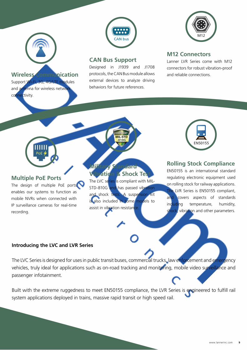
Military Standard Vibration & Shock Test The LVC series is compliant with MIL-
STD-810G and has passed vibration
and shock tests. A suspension kit
is also included in some models to
assist in vibration resistance.
Multiple PoE Ports The design of multiple PoE ports
enables our systems to function as
mobile NVRs when connected with
IP surveillance cameras for real-time
recording.
Wireless CommunicationSupport Wi-Fi, 3G, 4G/LTE modules
and antenna for wireless network
connectivity.
Rolling Stock ComplianceEN50155 is an international standard
regulating electronic equipment used
on rolling stock for railway applications.
The LVR Series is EN50155 compliant,
and covers aspects of standards
including temperature, humidity,
shock, vibration and other parameters.
CAN Bus SupportDesigned in J1939 and J1708
protocols, the CAN Bus module allows
external devices to analyze driving
behaviors for future references.
M12 ConnectorsLanner LVR Series come with M12
connectors for robust vibration-proof
and reliable connections.
Introducing the LVC and LVR Series
The LVC Series is designed for uses in public transit buses, commercial trucks, law enforcement and emergency
vehicles, truly ideal for applications such as on-road tracking and monitoring, mobile video surveillance and
passenger infotainment.
Built with the extreme ruggedness to meet EN50155 compliance, the LVR Series is engineered to fulfill rail
system applications deployed in trains, massive rapid transit or high speed rail.
CAN busM12
EN50155
PoE

10 www.lannerinc.com
In-vehicle Application Scenarios
To optimize transportation cost and secure driver’s safety, Lanner LVC-2000 Series provide total
solution for truck fleet management. As the center of truck applications, LVC-2000 Series provide
rich I/O and expansion capability to connect front/rear IP Camera, RFID scanner, temperature
sensor, monitor, TPMS receiver, anti-doze / alcohol detector and Wi-Fi/3G/4G interface cards.
The whole management system makes driver and the company HQ a more efficient and safe
work place.
Fleet Management
LVC-2000/2001
- Fanless Vehicle Gateway Controller
- Intel® Atom™ E3845 1.91 GHz CPU
- Support VGA/HDMI & 1 or 2 x RJ45 GbE Port(s)
- Optional CAN Bus Support
- E-Mark Certification
Target Applications:
- Digital Logistics / Fleet Management
- Dispatch / Route Optimization
- Audio Intercom
- GPS Tracking
- Emergency Alarm System
- Driver Advisor System
Coaxial Cable
Serial Cable
HDMI Cable
Ethernet Cable
Control Center
Rear CameraTPMS Emitter
TPMS Receiver
OBDII
Monitor
Front Camera
GPS Antenna
Driver ID Card Reader
LVC-2001

www.lannerinc.com 11
As a central control computer for buses, LVC-5000 connects various devices to form intelligent
services to driver, passengers and communicate with head office. Through LVC-5000’s rich
I/O connection, including it’s GPS/G-sensor, CAN bus, COM and multiple display capability,
it can perform digital signage infotainment, fleet management, surveillance, recording, Wi-Fi
hot spot, TPMS (Tire Pressure Measurement System) emitter, e-ticketing, audio intercom, door
control and people counting, to provide secure and comfortable journey for bus transportation
experience.
Intelligent Bus
LVC-5000
- Multi-purpose Vehicle Computer
- Intel® 847E or 1047UE CPU and HM65 Chipset
- Mobile NVR with 4 x PoE Ports
- 1 x Swappable 2.5” Drive Bay
- Suspension Kit
- E-Mark Certification
Target Applications:
- Passenger Information
- Digital Signage
- Wi-Fi Hot Spot
- Dispatch
- GPS Tracking
- Emergency Alarm System
- Driver Advisor System
- TPMS
- E-ticket
PoE Cable
Serial Cable
HDMI Cable
Coaxial Cable
DI/DO Cable
Digital Signage
Camera
AP
TPMS
Passenger Information
Door Sensor
Ticket Reader
GPS Antenna
Driver ID Reader
LVC-5000
12 www.lannerinc.com
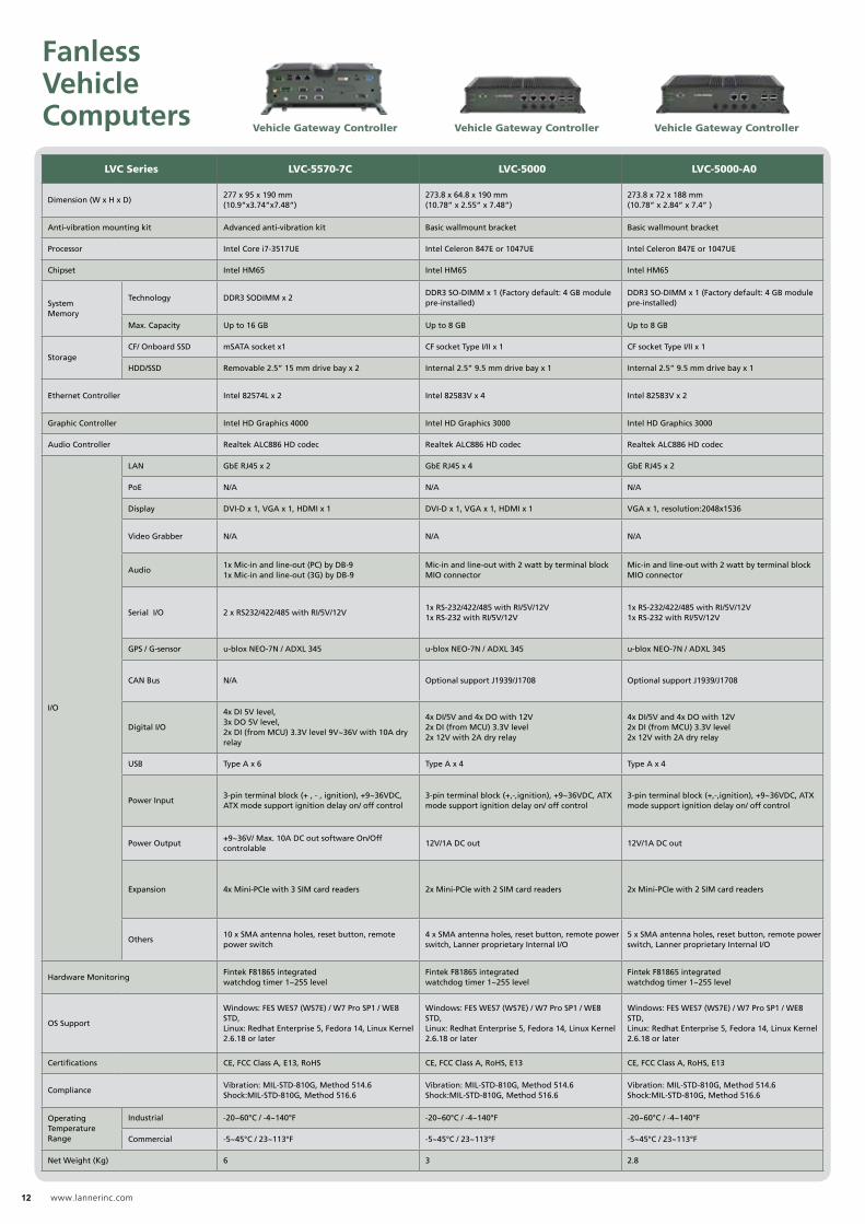
LVC Series LVC-5570-7C LVC-5000 LVC-5000-A0 LVC-2000 LVC-2001 LVC-5570D4-CA LVC-5000-A1
Dimension (W x H x D)277 x 95 x 190 mm (10.9”x3.74”x7.48”)
273.8 x 64.8 x 190 mm (10.78” x 2.55” x 7.48”)
273.8 x 72 x 188 mm (10.78” x 2.84” x 7.4” )
198 x 52 x 165 mm (7.8”x 2”x 6.5”)
198 x 52 x 185 mm (7.8”x 2”x 7.28”)
276.52 x 85.26 x 190 mm(10.86”x3.35”x 7.48”)
273.8 x 72 x 190 mm(10.78” x 2.83” x 7.48”)
Anti-vibration mounting kit Advanced anti-vibration kit Basic wallmount bracket Basic wallmount bracket Basic wallmount bracket Basic wallmount bracket Advanced anti-vibration kit Advanced anti-vibration kit
Processor Intel Core i7-3517UE Intel Celeron 847E or 1047UE Intel Celeron 847E or 1047UE Intel Atom E3845 1.91 GHz Intel Atom E3845 1.91 GHz Intel Celeron 1020E Intel Celeron 1047UE 1.4 GHz
Chipset Intel HM65 Intel HM65 Intel HM65 N/A N/A Intel HM65 Intel HM65
SystemMemory
Technology DDR3 SODIMM x 2DDR3 SO-DIMM x 1 (Factory default: 4 GB module pre-installed)
DDR3 SO-DIMM x 1 (Factory default: 4 GB module pre-installed)
DDR3L SO-DIMM x 1 DDR3L SO-DIMM x 1 DDR3 SO-DIMM x 2DDR3 SO-DIMM x 1 (Factory default: 4 GB module pre-installed)
Max. Capacity Up to 16 GB Up to 8 GB Up to 8 GB Up to 8 GB Up to 8 GB Up to 16 GB Up to 8 GB
StorageCF/ Onboard SSD mSATA socket x1 CF socket Type I/II x 1 CF socket Type I/II x 1 mSATA x 1 mSATA x 1 CF socket Type II x 1 CF socket Type I/II x 1
HDD/SSD Removable 2.5” 15 mm drive bay x 2 Internal 2.5” 9.5 mm drive bay x 1 Internal 2.5” 9.5 mm drive bay x 1 Internal 2.5” 15 mm drive bay x 1 Internal 2.5” 15 mm drive bay x 1 Removable 2.5” 9.5mm drive bay x 2 Removable 2.5” 15mm drive bay x 1
Ethernet Controller Intel 82574L x 2 Intel 82583V x 4 Intel 82583V x 2 Intel i210IT x1 Intel i210IT x 2 Intel 82574L x 2 Intel 82583V x 4
Graphic Controller Intel HD Graphics 4000 Intel HD Graphics 3000 Intel HD Graphics 3000 Intel HD Graphics Intel HD Graphics Intel HD Graphics 4000 Intel HD Graphics 4000
Audio Controller Realtek ALC886 HD codec Realtek ALC886 HD codec Realtek ALC886 HD codec Realtek ALC886 HD codec Realtek ALC886 HD codec Realtek ALC886 HD codec Realtek ALC886 HD codec
I/O
LAN GbE RJ45 x 2 GbE RJ45 x 4 GbE RJ45 x 2 GbE RJ45 x 1 GbE RJ45 x 2 GbE RJ45 x 2 GbE RJ45 x 4
PoE N/A N/A N/A N/A N/A N/A N/A
Display DVI-D x 1, VGA x 1, HDMI x 1 DVI-D x 1, VGA x 1, HDMI x 1 VGA x 1, resolution:2048x1536 VGA x 1, HDMI x 1 VGA x 1, HDMI x 1 DVI-D x 1, VGA x 1, HDMI x 1 DVI-D x 1, VGA x 1, HDMI x 1
Video Grabber N/A N/A N/A N/A N/AYUAN SC330N4 4ch analogueinput, video input 1~4
Techwell TW5866 8ch analogue inputs
Audio1x Mic-in and line-out (PC) by DB-91x Mic-in and line-out (3G) by DB-9
Mic-in and line-out with 2 watt by terminal block MIO connector
Mic-in and line-out with 2 watt by terminal block MIO connector
Internal Mic-in and line-out pin-header Mic-in x1 and line-out x1 3.5mm phone jack1x Mic-in and line-out (PC) 1x Mic-in and line-out (3G)
Mic-in and line-out with 2 watt by terminal block MIO connector
Serial I/O 2 x RS232/422/485 with RI/5V/12V1x RS-232/422/485 with RI/5V/12V1x RS-232 with RI/5V/12V
1x RS-232/422/485 with RI/5V/12V1x RS-232 with RI/5V/12V
COM1 : 1 x RS-232/422/485 with RI/5V/12V; COM2 and COM3 : 2 x RS-232 optional selection for 2 x CAN bus
COM1/COM2: 2x RS-232/422/485 with RI/5V/12VCOM3: RS-232 for one optional CAN Bus
2 x RS232/422/485 with RI/5V/12V1 x RS-232/422/485 with RI/5V/12V1 x RS-232 with RI/5V/12V
GPS / G-sensor u-blox NEO-7N / ADXL 345 u-blox NEO-7N / ADXL 345 u-blox NEO-7N / ADXL 345 u-blox NEO-7N / ADXL 345 u-blox NEO-7N / ADXL 345 u-blox NEO-7N / ADXL 345 u-blox NEO-7N / ADXL 345
CAN Bus N/A Optional support J1939/J1708 Optional support J1939/J1708Optional support 2x J1939 / J1708 on COM 2 and COM3 port
Optional support J1939/J1708 on COM3 port N/A N/A
Digital I/O
4x DI 5V level, 3x DO 5V level, 2x DI (from MCU) 3.3V level 9V~36V with 10A dry relay
4x DI/5V and 4x DO with 12V2x DI (from MCU) 3.3V level2x 12V with 2A dry relay
4x DI/5V and 4x DO with 12V2x DI (from MCU) 3.3V level2x 12V with 2A dry relay
4x DI/5V and 4x DO with 12V2x DI (from MCU) 3.3V level2x 12V with 2A dry relay
4x DI/5V and 4x DO with 12V2x DI (from MCU) 3.3V level
4x DI 5V level, 3x DO 5V level, 2x DI (from MCU) 3.3V level
4x DI and 4x DO with 12V level by jumper setting2x DI (from MCU) 3.3V level2x DO 12/24V with 2A relay
USB Type A x 6 Type A x 4 Type A x 4 USB 3.0 Type A x 1 USB 3.0 Type A x 1, USB 2.0 Type A x 1 Type A x 6 Type A x 4
Power Input3-pin terminal block (+ , - , ignition), +9~36VDC, ATX mode support ignition delay on/ off control
3-pin terminal block (+,-,ignition), +9~36VDC, ATX mode support ignition delay on/ off control
3-pin terminal block (+,-,ignition), +9~36VDC, ATX mode support ignition delay on/ off control
3-pin terminal block (+,-,ignition), +9~36VDC, ATX mode support ignition delay on/ off control
3-pin terminal block (+,-,ignition), +9~36VDC, ATX mode support ignition delay on/ off control
3-pin terminal block (+ , - , ignition), +9~36VDC, ATX mode support ignition delay on/ off control
3-pin terminal block (+,-,ignition), +9~36VDC, ATX mode support ignition delay on/ off control
Power Output+9~36V/ Max. 10A DC out software On/Off controlable
12V/1A DC out 12V/1A DC out 12V/1A DC out 12V/1A DC out9~36V/ Max. 10A DC out software on/off controlable
12V/1A DC out
Expansion 4x Mini-PCIe with 3 SIM card readers 2x Mini-PCIe with 2 SIM card readers 2x Mini-PCIe with 2 SIM card readers1x full-size Mini-PCIe socket with SIM card reader, 1x half-size Mini-PCIe socket
2x full-size mini-PCIe socket ( 1x USB+PCIe+2x SIM; 1x USB+2 x SIM )1x half-size mini-PCIe socket ( USB+PCIe) ;4x SIM card readers
4x Mini-PCIe with 3 SIM card readers 2x Mini-PCIe with 2 SIM card readers
Others10 x SMA antenna holes, reset button, remote power switch
4 x SMA antenna holes, reset button, remote power switch, Lanner proprietary Internal I/O
5 x SMA antenna holes, reset button, remote power switch, Lanner proprietary Internal I/O
4 x SMA antenna holes, reset button, remote power switch
4 x SMA antenna holes, reset button, remote power switch, Lanner proprietary Internal I/O
3 x SMA antenna holes, reset button, remote power switch
5 x SMA antenna holes, reset button, remote power switch
Hardware MonitoringFintek F81865 integrated watchdog timer 1~255 level
Fintek F81865 integrated watchdog timer 1~255 level
Fintek F81865 integrated watchdog timer 1~255 level
Fintek F81865 integrated watchdog timer 1~255 level
Fintek F81865 integrated watchdog timer 1~255 level
Fintek F81865 integrated watchdog timer 1~255 level
Fintek F81865 integrated watchdog timer 1~255 level
OS Support
Windows: FES WES7 (WS7E) / W7 Pro SP1 / WE8 STD, Linux: Redhat Enterprise 5, Fedora 14, Linux Kernel 2.6.18 or later
Windows: FES WES7 (WS7E) / W7 Pro SP1 / WE8 STD, Linux: Redhat Enterprise 5, Fedora 14, Linux Kernel 2.6.18 or later
Windows: FES WES7 (WS7E) / W7 Pro SP1 / WE8 STD, Linux: Redhat Enterprise 5, Fedora 14, Linux Kernel 2.6.18 or later
Windows: FES WES7 (WS7E) / W7 Pro SP1 / WE8 STD, Linux: Redhat Enterprise 5, Fedora 14, Linux Kernel 2.6.18 or later
Windows: FES WES7 (WS7E) / W7 Pro SP1 / WE8 STD, Linux: Redhat Enterprise 5, Fedora 14, Linux Kernel 2.6.18 or later
Windows: FES WES7 (WS7E) / W7 Pro SP1 / WE8 STD, Linux: Redhat Enterprise 5, Fedora 14, Linux Kernel 2.6.18 or later
Windows: FES WES7 (WS7E) / W7 Pro SP1 / WE8 STD, Linux: Redhat Enterprise 5, Fedora 14, Linux Kernel 2.6.18 or later
Certifications CE, FCC Class A, E13, RoHS CE, FCC Class A, RoHS, E13 CE, FCC Class A, RoHS, E13 CE, FCC Class A, RoHS, E13, SAE J1455 CE, FCC Class A, RoHS, E13 CE, FCC Class A, E13, RoHS CE, FCC Class A, RoHS, E13
ComplianceVibration: MIL-STD-810G, Method 514.6Shock:MIL-STD-810G, Method 516.6
Vibration: MIL-STD-810G, Method 514.6Shock:MIL-STD-810G, Method 516.6
Vibration: MIL-STD-810G, Method 514.6Shock:MIL-STD-810G, Method 516.6
Vibration: MIL-STD-810G, Method 514.6Shock:MIL-STD-810G, Method 516.6
Vibration: MIL-STD-810G, Method 514.6Shock:MIL-STD-810G, Method 516.6
Vibration: MIL-STD-810G, Method 514.6Shock:MIL-STD-810G, Method 516.6
Vibration: MIL-STD-810G, Method 514.6Shock:MIL-STD-810G, Method 516.6
Operating Temperature Range
Industrial -20~60°C / -4~140°F -20~60°C / -4~140°F -20~60°C / -4~140°F -20~60°C / -4~140°F -20~60°C / -4~140°F -20~55°C / -4~131°F -20~60°C / -4~140°F
Commercial -5~45°C / 23~113°F -5~45°C / 23~113°F -5~45°C / 23~113°F -5~45°C / 23~113°F -5~45°C / 23~113°F -5~45°C / 23~113°F -5~45°C / 23~113°F
Net Weight (Kg) 6 3 2.8 1.5 1.8 6 4.2
Fanless Vehicle Computers
Vehicle Gateway Controller Vehicle Gateway Controller Vehicle Gateway Controller

www.lannerinc.com 13
LVC Series LVC-5570-7C LVC-5000 LVC-5000-A0 LVC-2000 LVC-2001 LVC-5570D4-CA LVC-5000-A1
Dimension (W x H x D)277 x 95 x 190 mm (10.9”x3.74”x7.48”)
273.8 x 64.8 x 190 mm (10.78” x 2.55” x 7.48”)
273.8 x 72 x 188 mm (10.78” x 2.84” x 7.4” )
198 x 52 x 165 mm (7.8”x 2”x 6.5”)
198 x 52 x 185 mm (7.8”x 2”x 7.28”)
276.52 x 85.26 x 190 mm(10.86”x3.35”x 7.48”)
273.8 x 72 x 190 mm(10.78” x 2.83” x 7.48”)
Anti-vibration mounting kit Advanced anti-vibration kit Basic wallmount bracket Basic wallmount bracket Basic wallmount bracket Basic wallmount bracket Advanced anti-vibration kit Advanced anti-vibration kit
Processor Intel Core i7-3517UE Intel Celeron 847E or 1047UE Intel Celeron 847E or 1047UE Intel Atom E3845 1.91 GHz Intel Atom E3845 1.91 GHz Intel Celeron 1020E Intel Celeron 1047UE 1.4 GHz
Chipset Intel HM65 Intel HM65 Intel HM65 N/A N/A Intel HM65 Intel HM65
SystemMemory
Technology DDR3 SODIMM x 2DDR3 SO-DIMM x 1 (Factory default: 4 GB module pre-installed)
DDR3 SO-DIMM x 1 (Factory default: 4 GB module pre-installed)
DDR3L SO-DIMM x 1 DDR3L SO-DIMM x 1 DDR3 SO-DIMM x 2DDR3 SO-DIMM x 1 (Factory default: 4 GB module pre-installed)
Max. Capacity Up to 16 GB Up to 8 GB Up to 8 GB Up to 8 GB Up to 8 GB Up to 16 GB Up to 8 GB
StorageCF/ Onboard SSD mSATA socket x1 CF socket Type I/II x 1 CF socket Type I/II x 1 mSATA x 1 mSATA x 1 CF socket Type II x 1 CF socket Type I/II x 1
HDD/SSD Removable 2.5” 15 mm drive bay x 2 Internal 2.5” 9.5 mm drive bay x 1 Internal 2.5” 9.5 mm drive bay x 1 Internal 2.5” 15 mm drive bay x 1 Internal 2.5” 15 mm drive bay x 1 Removable 2.5” 9.5mm drive bay x 2 Removable 2.5” 15mm drive bay x 1
Ethernet Controller Intel 82574L x 2 Intel 82583V x 4 Intel 82583V x 2 Intel i210IT x1 Intel i210IT x 2 Intel 82574L x 2 Intel 82583V x 4
Graphic Controller Intel HD Graphics 4000 Intel HD Graphics 3000 Intel HD Graphics 3000 Intel HD Graphics Intel HD Graphics Intel HD Graphics 4000 Intel HD Graphics 4000
Audio Controller Realtek ALC886 HD codec Realtek ALC886 HD codec Realtek ALC886 HD codec Realtek ALC886 HD codec Realtek ALC886 HD codec Realtek ALC886 HD codec Realtek ALC886 HD codec
I/O
LAN GbE RJ45 x 2 GbE RJ45 x 4 GbE RJ45 x 2 GbE RJ45 x 1 GbE RJ45 x 2 GbE RJ45 x 2 GbE RJ45 x 4
PoE N/A N/A N/A N/A N/A N/A N/A
Display DVI-D x 1, VGA x 1, HDMI x 1 DVI-D x 1, VGA x 1, HDMI x 1 VGA x 1, resolution:2048x1536 VGA x 1, HDMI x 1 VGA x 1, HDMI x 1 DVI-D x 1, VGA x 1, HDMI x 1 DVI-D x 1, VGA x 1, HDMI x 1
Video Grabber N/A N/A N/A N/A N/AYUAN SC330N4 4ch analogueinput, video input 1~4
Techwell TW5866 8ch analogue inputs
Audio1x Mic-in and line-out (PC) by DB-91x Mic-in and line-out (3G) by DB-9
Mic-in and line-out with 2 watt by terminal block MIO connector
Mic-in and line-out with 2 watt by terminal block MIO connector
Internal Mic-in and line-out pin-header Mic-in x1 and line-out x1 3.5mm phone jack1x Mic-in and line-out (PC) 1x Mic-in and line-out (3G)
Mic-in and line-out with 2 watt by terminal block MIO connector
Serial I/O 2 x RS232/422/485 with RI/5V/12V1x RS-232/422/485 with RI/5V/12V1x RS-232 with RI/5V/12V
1x RS-232/422/485 with RI/5V/12V1x RS-232 with RI/5V/12V
COM1 : 1 x RS-232/422/485 with RI/5V/12V; COM2 and COM3 : 2 x RS-232 optional selection for 2 x CAN bus
COM1/COM2: 2x RS-232/422/485 with RI/5V/12VCOM3: RS-232 for one optional CAN Bus
2 x RS232/422/485 with RI/5V/12V1 x RS-232/422/485 with RI/5V/12V1 x RS-232 with RI/5V/12V
GPS / G-sensor u-blox NEO-7N / ADXL 345 u-blox NEO-7N / ADXL 345 u-blox NEO-7N / ADXL 345 u-blox NEO-7N / ADXL 345 u-blox NEO-7N / ADXL 345 u-blox NEO-7N / ADXL 345 u-blox NEO-7N / ADXL 345
CAN Bus N/A Optional support J1939/J1708 Optional support J1939/J1708Optional support 2x J1939 / J1708 on COM 2 and COM3 port
Optional support J1939/J1708 on COM3 port N/A N/A
Digital I/O
4x DI 5V level, 3x DO 5V level, 2x DI (from MCU) 3.3V level 9V~36V with 10A dry relay
4x DI/5V and 4x DO with 12V2x DI (from MCU) 3.3V level2x 12V with 2A dry relay
4x DI/5V and 4x DO with 12V2x DI (from MCU) 3.3V level2x 12V with 2A dry relay
4x DI/5V and 4x DO with 12V2x DI (from MCU) 3.3V level2x 12V with 2A dry relay
4x DI/5V and 4x DO with 12V2x DI (from MCU) 3.3V level
4x DI 5V level, 3x DO 5V level, 2x DI (from MCU) 3.3V level
4x DI and 4x DO with 12V level by jumper setting2x DI (from MCU) 3.3V level2x DO 12/24V with 2A relay
USB Type A x 6 Type A x 4 Type A x 4 USB 3.0 Type A x 1 USB 3.0 Type A x 1, USB 2.0 Type A x 1 Type A x 6 Type A x 4
Power Input3-pin terminal block (+ , - , ignition), +9~36VDC, ATX mode support ignition delay on/ off control
3-pin terminal block (+,-,ignition), +9~36VDC, ATX mode support ignition delay on/ off control
3-pin terminal block (+,-,ignition), +9~36VDC, ATX mode support ignition delay on/ off control
3-pin terminal block (+,-,ignition), +9~36VDC, ATX mode support ignition delay on/ off control
3-pin terminal block (+,-,ignition), +9~36VDC, ATX mode support ignition delay on/ off control
3-pin terminal block (+ , - , ignition), +9~36VDC, ATX mode support ignition delay on/ off control
3-pin terminal block (+,-,ignition), +9~36VDC, ATX mode support ignition delay on/ off control
Power Output+9~36V/ Max. 10A DC out software On/Off controlable
12V/1A DC out 12V/1A DC out 12V/1A DC out 12V/1A DC out9~36V/ Max. 10A DC out software on/off controlable
12V/1A DC out
Expansion 4x Mini-PCIe with 3 SIM card readers 2x Mini-PCIe with 2 SIM card readers 2x Mini-PCIe with 2 SIM card readers1x full-size Mini-PCIe socket with SIM card reader, 1x half-size Mini-PCIe socket
2x full-size mini-PCIe socket ( 1x USB+PCIe+2x SIM; 1x USB+2 x SIM )1x half-size mini-PCIe socket ( USB+PCIe) ;4x SIM card readers
4x Mini-PCIe with 3 SIM card readers 2x Mini-PCIe with 2 SIM card readers
Others10 x SMA antenna holes, reset button, remote power switch
4 x SMA antenna holes, reset button, remote power switch, Lanner proprietary Internal I/O
5 x SMA antenna holes, reset button, remote power switch, Lanner proprietary Internal I/O
4 x SMA antenna holes, reset button, remote power switch
4 x SMA antenna holes, reset button, remote power switch, Lanner proprietary Internal I/O
3 x SMA antenna holes, reset button, remote power switch
5 x SMA antenna holes, reset button, remote power switch
Hardware MonitoringFintek F81865 integrated watchdog timer 1~255 level
Fintek F81865 integrated watchdog timer 1~255 level
Fintek F81865 integrated watchdog timer 1~255 level
Fintek F81865 integrated watchdog timer 1~255 level
Fintek F81865 integrated watchdog timer 1~255 level
Fintek F81865 integrated watchdog timer 1~255 level
Fintek F81865 integrated watchdog timer 1~255 level
OS Support
Windows: FES WES7 (WS7E) / W7 Pro SP1 / WE8 STD, Linux: Redhat Enterprise 5, Fedora 14, Linux Kernel 2.6.18 or later
Windows: FES WES7 (WS7E) / W7 Pro SP1 / WE8 STD, Linux: Redhat Enterprise 5, Fedora 14, Linux Kernel 2.6.18 or later
Windows: FES WES7 (WS7E) / W7 Pro SP1 / WE8 STD, Linux: Redhat Enterprise 5, Fedora 14, Linux Kernel 2.6.18 or later
Windows: FES WES7 (WS7E) / W7 Pro SP1 / WE8 STD, Linux: Redhat Enterprise 5, Fedora 14, Linux Kernel 2.6.18 or later
Windows: FES WES7 (WS7E) / W7 Pro SP1 / WE8 STD, Linux: Redhat Enterprise 5, Fedora 14, Linux Kernel 2.6.18 or later
Windows: FES WES7 (WS7E) / W7 Pro SP1 / WE8 STD, Linux: Redhat Enterprise 5, Fedora 14, Linux Kernel 2.6.18 or later
Windows: FES WES7 (WS7E) / W7 Pro SP1 / WE8 STD, Linux: Redhat Enterprise 5, Fedora 14, Linux Kernel 2.6.18 or later
Certifications CE, FCC Class A, E13, RoHS CE, FCC Class A, RoHS, E13 CE, FCC Class A, RoHS, E13 CE, FCC Class A, RoHS, E13, SAE J1455 CE, FCC Class A, RoHS, E13 CE, FCC Class A, E13, RoHS CE, FCC Class A, RoHS, E13
ComplianceVibration: MIL-STD-810G, Method 514.6Shock:MIL-STD-810G, Method 516.6
Vibration: MIL-STD-810G, Method 514.6Shock:MIL-STD-810G, Method 516.6
Vibration: MIL-STD-810G, Method 514.6Shock:MIL-STD-810G, Method 516.6
Vibration: MIL-STD-810G, Method 514.6Shock:MIL-STD-810G, Method 516.6
Vibration: MIL-STD-810G, Method 514.6Shock:MIL-STD-810G, Method 516.6
Vibration: MIL-STD-810G, Method 514.6Shock:MIL-STD-810G, Method 516.6
Vibration: MIL-STD-810G, Method 514.6Shock:MIL-STD-810G, Method 516.6
Operating Temperature Range
Industrial -20~60°C / -4~140°F -20~60°C / -4~140°F -20~60°C / -4~140°F -20~60°C / -4~140°F -20~60°C / -4~140°F -20~55°C / -4~131°F -20~60°C / -4~140°F
Commercial -5~45°C / 23~113°F -5~45°C / 23~113°F -5~45°C / 23~113°F -5~45°C / 23~113°F -5~45°C / 23~113°F -5~45°C / 23~113°F -5~45°C / 23~113°F
Net Weight (Kg) 6 3 2.8 1.5 1.8 6 4.2
4ch Surveillance DVR 8ch Surveillance DVRVehicle Gateway Controller Vehicle Gateway Controller

14 www.lannerinc.com
LVC Series LVC-5000-A2 LVC-5000-A5 LVC-5000-A6 LVC-5770-7D LVC-5000-B1 LVC-5000-B2 LVC-5000-B3 LVC-7000-N10
Dimension (W x H x D)273.8 x 72 x 190 mm(10.78” x 2.83” x 7.48”)
273.8 x 72 x 190 mm(10.78” x 2.83” x 7.48”)
273.8 x 72 x 190 mm(10.78” x 2.83” x 7.48”)
276.4 x 95 x 190 mm (10.88” x 3.7” x 7.8” )
273.8 x 72 x 190 mm(10.78” x 2.83” x 7.48”)
273.8 x 72 x 190 mm(10.78” x 2.83” x 7.48”)
273.8 x 72 x 190 mm(10.78” x 2.83” x 7.48”)
273.8 x 92 x 219 mm(10.78” x 3.62” x 8.62”)
Anti-vibration mounting kit Advanced anti-vibration kit Advanced anti-vibration kit Advanced anti-vibration kit Advanced anti-vibration kit Advanced anti-vibration kit Advanced anti-vibration kit Advanced anti-vibration kit Advanced anti-vibration kit
Processor Intel Celeron 1047UE Intel Core i7-3517UE Intel Core i7-3517UE Intel Core i7-3517UE Intel Celeron 1047UE Intel Core i7-3517UE Intel Core i7-3517UE Intel Core i7-6600U
Chipset Intel HM65 Intel HM65 Intel HM65 Intel HM65 Intel HM65 Intel HM65 Intel HM65 N/A
System TechnologyDDR3 SO-DIMM x 1 (Factory default: 4 GB module pre-installed)
DDR3 SO-DIMM x 1 (Factory default: 4 GB module pre-installed)
DDR3 SO-DIMM x 1 (Factory default: 4 GB module pre-installed)
DDR3 SO-DIMM x 2DDR3 SO-DIMM x 1 (Factory default: 4 GB module pre-installed)
DDR3 SO-DIMM x 1 (Factory default: 4 GB module pre-installed)
DDR3 SO-DIMM x 1 (Factory default: 4 GB module pre-installed)
DDR3L SO-DIMM x 2
Memory Max. Capacity Up to 8 GB Up to 16 GB Up to 8 GB Up to 16 GB Up to 8 GB Up to 8 GB Up to 8 GB Up to 16 GB
Storage
CF/ Onboard SSD CF socket Type I/II x 1 CF socket type I/II x 1 CF socket Type I/II x 1 mSATA x 1 CF socket Type I/II x 1 CF socket Type I/II x 1 CF socket Type I/II x 1, mSATA x 1 mSATA x 1
HDD/SSDRemovable 2.5” 15mm drive bay x 1
Removable 2.5” 15mm drive bay x 1
Removable 2.5” 15mm drive bay x 1
Removable 2.5” 15mm drive bay x 2
Removable 2.5” 15mm drive bay x 1, Internal 2.5” 15mm drive bay x 1
Removable 2.5” 15mm drive bay x 1 Removable 2.5” 15mm drive bay x 1 Removable 2.5” 15mm drive bay x 2
Ethernet Controller Intel 82583V x 4 Intel 82583V x 4 Intel 82583V x 4 Intel 82574L x 2, 82583 x 8 Intel 82583V x 5 Intel 82583V x 5 Intel 82583V x 5 Intel I210IT x 10, i219LM x 1
Graphic Controller Intel HD Graphics 4000 Intel HD Graphics 4000 Intel HD Graphics 4000 Intel HD Graphics 4000 Intel HD Graphics 4000 Intel HD Graphics 4000 Intel HD Graphics 4000 Intel Integrated HD Graphics 520
Audio Controller Realtek ALC886 HD codec Realtek ALC886 HD codec Realtek ALC886 HD codec Realtek ALC886 HD codec Realtek ALC886 HD codec Realtek ALC886 HD codec Realtek ALC886 HD codec Realtek ALC886 HD codec
I/O
LAN GbE RJ45 x 4 GbE RJ45 x 4 with PoE GbE RJ45 x 4 with PoE GbE RJ45 x 2, GbE RJ45 x8 with PoE GbE RJ45 x 1, GbE RJ45 x 4 with PoE GbE RJ45 x 1, GbE RJ45 x 4 with PoE GbE RJ45 x 5 with PoE GbE RJ45 x 1, GbE RJ45 x8 with PoE
PoE N/AIEEE 802.3af PoE port x 4, internal PoE adapter
IEEE 802.3af PoE port x 4, internal PoE adapter
IEEE 802.3af PoE port x 8, external PoE adapter
IEEE 802.3af PoE port x 4, internal PoE adapter
IEEE 802.3af PoE port x 4, internal PoE adapter
IEEE 802.3af PoE port x 5, internal PoE adapter with on/off control
IEEE 802.3af PoE port x 10 for total 160W power output
Display DVI-D x 1, VGA x 1, HDMI x 1 DVI-D x 1, VGA x 1, HDMI x 1 DVI-D x 1, VGA x 1, HDMI x 1 DVI-D x 1, VGA x 1, HDMI x 1 DVI-D x 1, VGA x 1, HDMI x 1 DVI-D x 1, VGA x 1, HDMI x 1 DVI-D x 1, VGA x 1, HDMI x 1 DVI-D x 1, VGA x 1
Video Grabber Stretch S7100 16ch Analogue InputTechwell TW5866 8ch Analogue Inputs
Stretch S7100 16ch Analogue Input N/A N/A N/A N/A N/A
AudioMic-in and line-out with 2 watt by terminal block MIO connector
Mic-in and line-out with 2 watt by terminal block MIO connector
Mic-in and line-out with 2 watt by terminal block MIO connector
Mic-in and line-out with 2 watt by DB-9
Mic-in and line-out with 2 watt byterminal block MIO connector
Mic-in and line-out with 2 watt byterminal block MIO connector
Mic-in and line-out with 2 watt byterminal block MIO connector
Mic-in and line-out with 2 watt by DB-9
Serial I/O 1 x RS-232/422/485 with RI/5V/12V 1 x RS-232/422/485 with RI/5V/12V 1 x RS-232/422/485 with RI/5V/12V 2 x RS232/422/485 with RI/5V/12V1 x RS-232/422/485 with RI/5V/12V1 x RS-232 with RI/5V/12V
1 x RS-232/422/485 with RI/5V/12V1 x RS-232 with RI/5V/12V
1 x RS-232/422/485 with RI/5V/12V1 x RS-232 with RI/5V/12V
2 x RS232/422/485 with RI/5V/12V1 x RS-232 in MIO port
GPS / G-sensor u-blox NEO-7N / ADXL 345 u-blox NEO-7N / ADXL 345 u-blox NEO-7N / ADXL 345 u-blox NEO-7N / ADXL 345 u-blox NEO-7N / ADXL 345 u-blox NEO-7N / ADXL 345 u-blox NEO-7N / ADXL 345 u-blox NEO-M8L / ADXL 345
CAN Bus N/A N/A N/A N/A Optional support J1939 / J1708 CAN bus 2.0B support J1939 / J1708 Optional support J1939 / J1708 Optional support J1939 / J1708
Digital I/O
4x DI and 4x DO with 12V level by jumper setting2x DI (from MCU) 3.3V level2x DO 12/24V with 2A relay
4x DI and 4x DO with 12V level by jumper setting2x DI (from MCU) 3.3V level2x DO 12/24V with 2A relay
4x DI and 4x DO with 12V level by jumper setting2x DI (from MCU) 3.3V level2x DO 12/24V with 2A relay
4x DI 5V level3x DO 5V level2x DI (from MCU) 3.3V Level9V~36V with 10A dry relay
4x DI and 4x DO with 12V level by jumper setting2x DI (from MCU) 3.3V level2x DO 12/24V with 2A relay
4x DI and 4x DO with 12V level by jumper setting2x DI (from MCU) 3.3V level2x DO 12/24V with 2A relay
4x DI and 4x DO with 12V level by jumper setting2x DI (from MCU) 3.3V level2x DO 12/24V with 2A relay
7x DI 12V level7x DO 12V levelby by 1x 26-pin terminal block connector
USB Type A x 4 Type A x 4 Type A x 4 Type A x 6 Type A x 4 Type A x 4 Type A x 4USB 3.0 Type A x 4, internal USB 2.0 x2 with pin header
Power Input3-pin terminal block (+,-,ignition), +9~36VDC, ATX mode support ignition delay on/ off control
3-pin terminal block (+ , - , ignition), +9~36VDC, ATX mode support ignition delay on/ off control
3-pin terminal block (+,-,ignition), +9~36VDC, ATX mode support ignition delay on/ off control
3-pin terminal block (+,-,ignition), +9~36VDC, ATX mode support ignition delay on/ off control
3-pin terminal block (+,-,ignition), +9~36VDC, ATX mode support ignition delay on/ off control
3-pin terminal block (+,-,ignition), +9~36VDC, ATX mode support ignition delay on/ off control
3-pin terminal block (+,-,ignition), +9~36VDC, ATX mode support ignition delay on/ off control
4-pin terminal block (+,-,ignition), +9~36VDC, ATX mode support ignition delay on/ off control
Power Output 12V/1A DC out 12V/1A DC out 12V/1A DC out+9~36V/ max. 10A DC out software on/off controlable
12V/1A DC out 12V/1A DC out 12V/1A DC out +12V, 1A DC out software on/off controlable
Expansion2x Mini-PCIe with 2 SIM card readers
2x Mini-PCIe with 2 SIM card readers
2x Mini-PCIe with 2 SIM card readers
2x Mini-PCIe with 1 SIM card readers
3x Mini-PCIe with 3 SIM card readers 3x Mini-PCIe with 3 SIM card readers 2x Mini-PCIe with 2 SIM card readers
3x Mini-PCIe with 4 SIM card readers (1x removable bay for 1x mini-PCIe slot with two SIM card readers, 1x internal mini-PCIe slot with two SIM card readers)
Others5 x SMA antenna holes, reset button, remote power switch
5 x SMA antenna holes, reset button, remote power switch
5 x SMA antenna holes, reset button, remote power switch
6 x SMA antenna holes, reset button, remote power switch
5 x SMA antenna holes, reset button, remote power switch
5 x SMA antenna holes, reset button, remote power switch
5 x SMA antenna holes, reset button, remote power switch
7 x SMA antenna holes, reset button, remote power switch
Hardware MonitorFintek F81865 integrated watchdog timer 1~255 level
Fintek F81865 integrated watchdog timer 1~255 level
Fintek F81865 integrated watchdog timer 1~255 level
Fintek F81865 integrated watchdog timer 1~255 level
Fintek F81865 integrated watchdog timer 1~255 level
Fintek F81865 integrated watchdog timer 1~255 level
Fintek F81865 integrated watchdog timer 1~255 level
Fintek F81865 integrated watchdog timer 1~255 level
OS Support
Windows: FES WES7 (WS7E) / W7 Pro SP1 / WE8 STD, Linux: Redhat Enterprise 5, Fedora 14, Linux Kernel 2.6.18 or later
Windows: FES WES7 (WS7E) / W7 Pro SP1 / WE8 STD, Linux: Redhat Enterprise 5, Fedora 14, Linux Kernel 2.6.18 or later
Windows: FES WES7 (WS7E) / W7 Pro SP1 / WE8 STD, Linux: Redhat Enterprise 5, Fedora 14, Linux Kernel 2.6.18 or later
Windows: FES WES7 (WS7E) / W7 Pro SP1 / WE8 STD, Linux: Redhat Enterprise 5, Fedora 14, Linux Kernel 2.6.18 or later
Windows: FES WES7 (WS7E) / W7 Pro SP1 / WE8 STD, Linux: Redhat Enterprise 5, Fedora 14, Linux Kernel 2.6.18 or later
Windows: FES WES7 (WS7E) / W7 Pro SP1 / WE8 STD, Linux: Redhat Enterprise 5, Fedora 14, Linux Kernel 2.6.18 or later
Windows: FES WES7 (WS7E) / W7 Pro SP1 / WE8 STD, Linux: Redhat Enterprise 5, Fedora 14, Linux Kernel 2.6.18 or later
Windows: FES WES7 (WS7E) / W7 Pro SP1 / WE8 STD, Linux: Redhat Enterprise 5, Fedora 14, Linux Kernel 2.6.18 or later
Certifications CE, FCC Class A, RoHS, E13 CE, FCC Class A, E13, RoHS CE, FCC Class A, RoHS, E13 CE, FCC Class A, RoHS, E13 CE, FCC Class A, RoHS, E13 CE, FCC Class A, RoHS, E13 CE, FCC Class A, RoHS, E13 CE, FCC Class A, RoHS, E13
Compliance
Vibration: MIL-STD-810G, Method 514.6Shock:MIL-STD-810G, Method 516.6
Vibration: MIL-STD-810G, Method 514.6Shock:MIL-STD-810G, Method 516.6
Vibration: MIL-STD-810G, Method 514.6Shock:MIL-STD-810G, Method 516.6
Vibration: MIL-STD-810G, Method 514.6Shock:MIL-STD-810G, Method 516.6
Vibration: MIL-STD-810G, Method 514.6Shock:MIL-STD-810G, Method 516.6
Vibration: MIL-STD-810G, Method 514.6Shock:MIL-STD-810G, Method 516.6
Vibration: MIL-STD-810G, Method 514.6Shock:MIL-STD-810G, Method 516.6
Vibration: MIL-STD-810G, Method 514.6Shock:MIL-STD-810G, Method 516.6
Operating Temperature Range
with Industrial Components
-20~60°C / -4~140°F -20~60°C / -4~140°F -20~60°C / -4~140°F -20~60°C / -4~140°F -20~60°C / -4~140°F -20~60°C / -4~140°F -20~60°C / -4~140°F -20~60°C / -4~140°F
with Commercial Components
-5~45°C / 23~113°F -5~45°C / 23~113°F -5~45°C / 23~113°F -5~45°C / 23~113°F -5~45°C / 23~113°F -5~45°C / 23~113°F -5~45°C / 23~113°F -5~45°C / 23~113°F
Net Weight (Kg) 4.2 4.5 4.5 6 4 4 3.9 6
16ch Vehicle Surveillance DVR
8ch Vehicle SurveillanceDVR+NVR
16ch Vehicle Surveillance DVR+NVR
8ch Vehicle Surveillance NVR
Fanless Vehicle Computers

www.lannerinc.com 15
LVC Series LVC-5000-A2 LVC-5000-A5 LVC-5000-A6 LVC-5770-7D LVC-5000-B1 LVC-5000-B2 LVC-5000-B3 LVC-7000-N10
Dimension (W x H x D)273.8 x 72 x 190 mm(10.78” x 2.83” x 7.48”)
273.8 x 72 x 190 mm(10.78” x 2.83” x 7.48”)
273.8 x 72 x 190 mm(10.78” x 2.83” x 7.48”)
276.4 x 95 x 190 mm (10.88” x 3.7” x 7.8” )
273.8 x 72 x 190 mm(10.78” x 2.83” x 7.48”)
273.8 x 72 x 190 mm(10.78” x 2.83” x 7.48”)
273.8 x 72 x 190 mm(10.78” x 2.83” x 7.48”)
273.8 x 92 x 219 mm(10.78” x 3.62” x 8.62”)
Anti-vibration mounting kit Advanced anti-vibration kit Advanced anti-vibration kit Advanced anti-vibration kit Advanced anti-vibration kit Advanced anti-vibration kit Advanced anti-vibration kit Advanced anti-vibration kit Advanced anti-vibration kit
Processor Intel Celeron 1047UE Intel Core i7-3517UE Intel Core i7-3517UE Intel Core i7-3517UE Intel Celeron 1047UE Intel Core i7-3517UE Intel Core i7-3517UE Intel Core i7-6600U
Chipset Intel HM65 Intel HM65 Intel HM65 Intel HM65 Intel HM65 Intel HM65 Intel HM65 N/A
System TechnologyDDR3 SO-DIMM x 1 (Factory default: 4 GB module pre-installed)
DDR3 SO-DIMM x 1 (Factory default: 4 GB module pre-installed)
DDR3 SO-DIMM x 1 (Factory default: 4 GB module pre-installed)
DDR3 SO-DIMM x 2DDR3 SO-DIMM x 1 (Factory default: 4 GB module pre-installed)
DDR3 SO-DIMM x 1 (Factory default: 4 GB module pre-installed)
DDR3 SO-DIMM x 1 (Factory default: 4 GB module pre-installed)
DDR3L SO-DIMM x 2
Memory Max. Capacity Up to 8 GB Up to 16 GB Up to 8 GB Up to 16 GB Up to 8 GB Up to 8 GB Up to 8 GB Up to 16 GB
Storage
CF/ Onboard SSD CF socket Type I/II x 1 CF socket type I/II x 1 CF socket Type I/II x 1 mSATA x 1 CF socket Type I/II x 1 CF socket Type I/II x 1 CF socket Type I/II x 1, mSATA x 1 mSATA x 1
HDD/SSDRemovable 2.5” 15mm drive bay x 1
Removable 2.5” 15mm drive bay x 1
Removable 2.5” 15mm drive bay x 1
Removable 2.5” 15mm drive bay x 2
Removable 2.5” 15mm drive bay x 1, Internal 2.5” 15mm drive bay x 1
Removable 2.5” 15mm drive bay x 1 Removable 2.5” 15mm drive bay x 1 Removable 2.5” 15mm drive bay x 2
Ethernet Controller Intel 82583V x 4 Intel 82583V x 4 Intel 82583V x 4 Intel 82574L x 2, 82583 x 8 Intel 82583V x 5 Intel 82583V x 5 Intel 82583V x 5 Intel I210IT x 10, i219LM x 1
Graphic Controller Intel HD Graphics 4000 Intel HD Graphics 4000 Intel HD Graphics 4000 Intel HD Graphics 4000 Intel HD Graphics 4000 Intel HD Graphics 4000 Intel HD Graphics 4000 Intel Integrated HD Graphics 520
Audio Controller Realtek ALC886 HD codec Realtek ALC886 HD codec Realtek ALC886 HD codec Realtek ALC886 HD codec Realtek ALC886 HD codec Realtek ALC886 HD codec Realtek ALC886 HD codec Realtek ALC886 HD codec
I/O
LAN GbE RJ45 x 4 GbE RJ45 x 4 with PoE GbE RJ45 x 4 with PoE GbE RJ45 x 2, GbE RJ45 x8 with PoE GbE RJ45 x 1, GbE RJ45 x 4 with PoE GbE RJ45 x 1, GbE RJ45 x 4 with PoE GbE RJ45 x 5 with PoE GbE RJ45 x 1, GbE RJ45 x8 with PoE
PoE N/AIEEE 802.3af PoE port x 4, internal PoE adapter
IEEE 802.3af PoE port x 4, internal PoE adapter
IEEE 802.3af PoE port x 8, external PoE adapter
IEEE 802.3af PoE port x 4, internal PoE adapter
IEEE 802.3af PoE port x 4, internal PoE adapter
IEEE 802.3af PoE port x 5, internal PoE adapter with on/off control
IEEE 802.3af PoE port x 10 for total 160W power output
Display DVI-D x 1, VGA x 1, HDMI x 1 DVI-D x 1, VGA x 1, HDMI x 1 DVI-D x 1, VGA x 1, HDMI x 1 DVI-D x 1, VGA x 1, HDMI x 1 DVI-D x 1, VGA x 1, HDMI x 1 DVI-D x 1, VGA x 1, HDMI x 1 DVI-D x 1, VGA x 1, HDMI x 1 DVI-D x 1, VGA x 1
Video Grabber Stretch S7100 16ch Analogue InputTechwell TW5866 8ch Analogue Inputs
Stretch S7100 16ch Analogue Input N/A N/A N/A N/A N/A
AudioMic-in and line-out with 2 watt by terminal block MIO connector
Mic-in and line-out with 2 watt by terminal block MIO connector
Mic-in and line-out with 2 watt by terminal block MIO connector
Mic-in and line-out with 2 watt by DB-9
Mic-in and line-out with 2 watt byterminal block MIO connector
Mic-in and line-out with 2 watt byterminal block MIO connector
Mic-in and line-out with 2 watt byterminal block MIO connector
Mic-in and line-out with 2 watt by DB-9
Serial I/O 1 x RS-232/422/485 with RI/5V/12V 1 x RS-232/422/485 with RI/5V/12V 1 x RS-232/422/485 with RI/5V/12V 2 x RS232/422/485 with RI/5V/12V1 x RS-232/422/485 with RI/5V/12V1 x RS-232 with RI/5V/12V
1 x RS-232/422/485 with RI/5V/12V1 x RS-232 with RI/5V/12V
1 x RS-232/422/485 with RI/5V/12V1 x RS-232 with RI/5V/12V
2 x RS232/422/485 with RI/5V/12V1 x RS-232 in MIO port
GPS / G-sensor u-blox NEO-7N / ADXL 345 u-blox NEO-7N / ADXL 345 u-blox NEO-7N / ADXL 345 u-blox NEO-7N / ADXL 345 u-blox NEO-7N / ADXL 345 u-blox NEO-7N / ADXL 345 u-blox NEO-7N / ADXL 345 u-blox NEO-M8L / ADXL 345
CAN Bus N/A N/A N/A N/A Optional support J1939 / J1708 CAN bus 2.0B support J1939 / J1708 Optional support J1939 / J1708 Optional support J1939 / J1708
Digital I/O
4x DI and 4x DO with 12V level by jumper setting2x DI (from MCU) 3.3V level2x DO 12/24V with 2A relay
4x DI and 4x DO with 12V level by jumper setting2x DI (from MCU) 3.3V level2x DO 12/24V with 2A relay
4x DI and 4x DO with 12V level by jumper setting2x DI (from MCU) 3.3V level2x DO 12/24V with 2A relay
4x DI 5V level3x DO 5V level2x DI (from MCU) 3.3V Level9V~36V with 10A dry relay
4x DI and 4x DO with 12V level by jumper setting2x DI (from MCU) 3.3V level2x DO 12/24V with 2A relay
4x DI and 4x DO with 12V level by jumper setting2x DI (from MCU) 3.3V level2x DO 12/24V with 2A relay
4x DI and 4x DO with 12V level by jumper setting2x DI (from MCU) 3.3V level2x DO 12/24V with 2A relay
7x DI 12V level7x DO 12V levelby by 1x 26-pin terminal block connector
USB Type A x 4 Type A x 4 Type A x 4 Type A x 6 Type A x 4 Type A x 4 Type A x 4USB 3.0 Type A x 4, internal USB 2.0 x2 with pin header
Power Input3-pin terminal block (+,-,ignition), +9~36VDC, ATX mode support ignition delay on/ off control
3-pin terminal block (+ , - , ignition), +9~36VDC, ATX mode support ignition delay on/ off control
3-pin terminal block (+,-,ignition), +9~36VDC, ATX mode support ignition delay on/ off control
3-pin terminal block (+,-,ignition), +9~36VDC, ATX mode support ignition delay on/ off control
3-pin terminal block (+,-,ignition), +9~36VDC, ATX mode support ignition delay on/ off control
3-pin terminal block (+,-,ignition), +9~36VDC, ATX mode support ignition delay on/ off control
3-pin terminal block (+,-,ignition), +9~36VDC, ATX mode support ignition delay on/ off control
4-pin terminal block (+,-,ignition), +9~36VDC, ATX mode support ignition delay on/ off control
Power Output 12V/1A DC out 12V/1A DC out 12V/1A DC out+9~36V/ max. 10A DC out software on/off controlable
12V/1A DC out 12V/1A DC out 12V/1A DC out +12V, 1A DC out software on/off controlable
Expansion2x Mini-PCIe with 2 SIM card readers
2x Mini-PCIe with 2 SIM card readers
2x Mini-PCIe with 2 SIM card readers
2x Mini-PCIe with 1 SIM card readers
3x Mini-PCIe with 3 SIM card readers 3x Mini-PCIe with 3 SIM card readers 2x Mini-PCIe with 2 SIM card readers
3x Mini-PCIe with 4 SIM card readers (1x removable bay for 1x mini-PCIe slot with two SIM card readers, 1x internal mini-PCIe slot with two SIM card readers)
Others5 x SMA antenna holes, reset button, remote power switch
5 x SMA antenna holes, reset button, remote power switch
5 x SMA antenna holes, reset button, remote power switch
6 x SMA antenna holes, reset button, remote power switch
5 x SMA antenna holes, reset button, remote power switch
5 x SMA antenna holes, reset button, remote power switch
5 x SMA antenna holes, reset button, remote power switch
7 x SMA antenna holes, reset button, remote power switch
Hardware MonitorFintek F81865 integrated watchdog timer 1~255 level
Fintek F81865 integrated watchdog timer 1~255 level
Fintek F81865 integrated watchdog timer 1~255 level
Fintek F81865 integrated watchdog timer 1~255 level
Fintek F81865 integrated watchdog timer 1~255 level
Fintek F81865 integrated watchdog timer 1~255 level
Fintek F81865 integrated watchdog timer 1~255 level
Fintek F81865 integrated watchdog timer 1~255 level
OS Support
Windows: FES WES7 (WS7E) / W7 Pro SP1 / WE8 STD, Linux: Redhat Enterprise 5, Fedora 14, Linux Kernel 2.6.18 or later
Windows: FES WES7 (WS7E) / W7 Pro SP1 / WE8 STD, Linux: Redhat Enterprise 5, Fedora 14, Linux Kernel 2.6.18 or later
Windows: FES WES7 (WS7E) / W7 Pro SP1 / WE8 STD, Linux: Redhat Enterprise 5, Fedora 14, Linux Kernel 2.6.18 or later
Windows: FES WES7 (WS7E) / W7 Pro SP1 / WE8 STD, Linux: Redhat Enterprise 5, Fedora 14, Linux Kernel 2.6.18 or later
Windows: FES WES7 (WS7E) / W7 Pro SP1 / WE8 STD, Linux: Redhat Enterprise 5, Fedora 14, Linux Kernel 2.6.18 or later
Windows: FES WES7 (WS7E) / W7 Pro SP1 / WE8 STD, Linux: Redhat Enterprise 5, Fedora 14, Linux Kernel 2.6.18 or later
Windows: FES WES7 (WS7E) / W7 Pro SP1 / WE8 STD, Linux: Redhat Enterprise 5, Fedora 14, Linux Kernel 2.6.18 or later
Windows: FES WES7 (WS7E) / W7 Pro SP1 / WE8 STD, Linux: Redhat Enterprise 5, Fedora 14, Linux Kernel 2.6.18 or later
Certifications CE, FCC Class A, RoHS, E13 CE, FCC Class A, E13, RoHS CE, FCC Class A, RoHS, E13 CE, FCC Class A, RoHS, E13 CE, FCC Class A, RoHS, E13 CE, FCC Class A, RoHS, E13 CE, FCC Class A, RoHS, E13 CE, FCC Class A, RoHS, E13
Compliance
Vibration: MIL-STD-810G, Method 514.6Shock:MIL-STD-810G, Method 516.6
Vibration: MIL-STD-810G, Method 514.6Shock:MIL-STD-810G, Method 516.6
Vibration: MIL-STD-810G, Method 514.6Shock:MIL-STD-810G, Method 516.6
Vibration: MIL-STD-810G, Method 514.6Shock:MIL-STD-810G, Method 516.6
Vibration: MIL-STD-810G, Method 514.6Shock:MIL-STD-810G, Method 516.6
Vibration: MIL-STD-810G, Method 514.6Shock:MIL-STD-810G, Method 516.6
Vibration: MIL-STD-810G, Method 514.6Shock:MIL-STD-810G, Method 516.6
Vibration: MIL-STD-810G, Method 514.6Shock:MIL-STD-810G, Method 516.6
Operating Temperature Range
with Industrial Components
-20~60°C / -4~140°F -20~60°C / -4~140°F -20~60°C / -4~140°F -20~60°C / -4~140°F -20~60°C / -4~140°F -20~60°C / -4~140°F -20~60°C / -4~140°F -20~60°C / -4~140°F
with Commercial Components
-5~45°C / 23~113°F -5~45°C / 23~113°F -5~45°C / 23~113°F -5~45°C / 23~113°F -5~45°C / 23~113°F -5~45°C / 23~113°F -5~45°C / 23~113°F -5~45°C / 23~113°F
Net Weight (Kg) 4.2 4.5 4.5 6 4 4 3.9 6
4ch Vehicle Surveillance NVR
4ch Vehicle Surveillance NVR
4ch Vehicle Surveillance NVR
10ch Vehicle Surveillance NVR

16 www.lannerinc.com
Wireless AP
IP Camera
Intercom
Passenger Information
Wireless AP
IP Camera
Intercom
Monitor
PoE Cable
Serial Cable
HDMI Cable
Ethernet CableLVR-2010
LVR-8300
LVR-6000
Rolling Stock Application Scenarios
LVR-8300
- Rackmount Rolling Stock Computer
- Intel® Core™ i5-4422E Processor
- Support 16 x IEEE 802.11af PoE Ports
- Robust M12 I/O Ports
- Flexible I/O Module Design for Customization
- EN50155 Compliance
LVR-2010
- Fanless IP67 Vehicle Control Unit
- Intel® Atom™ E3845 1.91 GHz
- Robust M12 I/O Ports
- EN50155 Compliance -EN50155 Complian
Lanner’s newly launched rolling stock computing systems are purposely built for the increasing
demand of today’s digitalized and networked railway transportation systems. Through well-
experienced custom services, Lanner has innovated its LVR-series product line, all with EN50155
compliance and military standard endurance per request, ideal for data communication and
signal control, vehicle surveillance, and real-time information on railway environments.
Rolling Stock Computing
Target Applications:
- Onboard Video Surveillance
- Audio Intercom
- GPS Location-Based Service
- Digital Signage and Infotainment
- Emergency Alarm System
- Passenger Information System
- Driver Advisor System
- Wi-Fi Hot Spot
LVR-6000
- Fanless IP50 Surveillance Computer
- Intel® Core™ i7-6600U 2.6 GHz
- Support 10 x IEEE 802.11af PoE Ports
- Robust M12 I/O Ports
- EN50155 Compliance
16 www.lannerinc.com

www.lannerinc.com 17
LVR Series LVR-2010 LVR-6000 LVR-8300
Chassis
Dimensions (W x H x D) 268 x 210 x 86 mm(10.5” x 8.27” x 3.4” ) 268 x 110 x 190 mm (10.5” x 4.33” x 7.48”) 482.6 x 132 x 282 mm (19” x 5.2” x 15.7”)
IP Rated IP67 IP50 N/A
Processor Intel Atom E3845 1.91 GHz Intel Core i7-6600U 2.6 GHz Intel® Core™ i5-4422E Processor with QM87
Memory
Technology DDR3L 1333 SO-DIMM x 1 DDR4 1866/2133 SODIMM Socket x 1 DDR3L 1333/1600 SODIMM x 1
Max. CapacityUp to 4 GB (Factory default: 2 GB module pre-installed)
Up to 16 GB (Factory default: 8 GB module pre-installed)
Up to 8 GB (Factory default: 4 GB module pre-installed)
Storage
CF/ Onboard SSD mSATA socket x 1 mSATA socket x 1 mSATA socket x 1
HDD/SSD Internal 2.5” 15mm drive bay x 1 External 2.5” 15mm tray support 2 drive bays External 2.5” drive bay x4
Ethernet Controller Intel i210-IT x 2 Intel i210-IT x 11 Intel i217-LM x1 with AMT 9.5 support
Audio Controller Realtek ALC886 HD codec Realtek ALC886 HD codec Realtek ALC886 HD codec
I/O
LAN GbE RJ45 x 2 by M12 connectors GbE RJ45 x1 GbE LAN x1 by M12 connector
PoE N/A IEEE 802.3af standard PoE ports x10 IEEE 802.3af standard POE ports x16
DisplayVGA x 1, resolution up to 2048 x 1536HDMI/DP x 1, resolution up to 1920 x 1200
VGA x 1, resolution up to 2048 x 1536DVI-Ix 1, resolution up to 1920 x 1200
VGA x 1, resolution up to 2048 x 1536
Audio Mic-in and Line-out by HD Audio Mic-in and Line-out by HD Audio Mic-in and Line-out by HD Audio
Serial I/OCOM_A & B: RS232/422/485 x4COM_C: RS232 (TX-RX only) x6
RS-232/422/485 x2 with RI/5V/12V RS-232/422/485 x2 with RI/5V/12V
GPS / G-sensor u-blox NEO-7N / ADXL 345u-blox NEO-M8U UDR with Dead Reckoning & 3D Inertial Sensors
u-blox NEO-7N / ADXL 345
CAN CAN Bus J1939 & J1708 x1 CAN Bus J1939 & J1708 x1 CAN Bus J1939 & J1708 x1
Digital I/O 6x Digital Inputs & 6x Digital Outputs 8x Digital Inputs & 8x Digital Outputs 6x Digital Inputs & 6x Digital Outputs
USB 1 x USB 3.0, 2 x USB 2.0 by 2 x M12 connector2x USB 2.0 Type A; 2x USB 3.0 Type A; 1x additional M12 connector support 1x USB 2.0 & 1x USB 3.0
2x USB 2.0 Type A & 1x USB 3.0 Type A
Power InputDC 24V (+ , - , ignition) with option at DC 12/ 24/ 48/ 72/ 96/ 110V level
DC 24V (+ , - , ignition) with option at DC 12/ 24/ 48/ 72/ 96/ 110V level
DC 24V (+ , - , ignition) with option at DC 12/ 24/ 48/ 72/ 96/ 110V level
Power Output 12V/1A DC out 12V/2A DC out N/A
Expansion2 x Full-size Mini-PCIe socket with 2 SIM card readers, 1 x half-size Mini-PCIe socket
2 x Full-size Mini-PCIe Socket with 2 SIM card readers
3 x Mini-PCIe socket with 2 x SIM card readers per socket (total 6x) by optional LVK-MINIPCIE1 module
Antenna 4 x SMA antenna holes 6 x SMA antenna holes (includes GPS x1) 7x SMA antenna hole (includes GPS x1)
Hardware MonitoringFintek F81865 integrated watchdog timer 1~255 level
Fintek F81865 integrated watchdog timer 1~255 level
Fintek F81865 integrated watchdog timer 1~255 level
OS SupportWindows: FES WES7 (WS7E) / W7 Pro SP1 / WE8 STDLinux: Redhat Enterprise 5, Fedora 14, Linux Kernel 2.6.18 or later
Windows: FES WES7 (WS7E) / W7 Pro SP1 / WE8 STDLinux: Redhat Enterprise 5, Fedora 14, Linux Kernel 2.6.18 or later
Windows: FES WES7 (WS7E) / W7 Pro SP1 / WE8 STD / W8.1Linux: Redhat Enterprise 5, Fedora 14, Linux Kernel 2.6.18 or later
Certifications EMC CE, FCC Class A, RoHS CE, FCC Class A, RoHS CE, FCC Class A, RoHS
Compliance
Ambient Internal Temperature
EN 50155 Tx (-40 ~ 70°C) EN 50155 Tx (-40 ~ 70°C) EN 50155 Tx (-40 ~ 70°C)
Shock and Vibration EN 61373 EN 61373 EN 61373
Interruptions of Voltage Supply
EN 50155 Class S2 EN 50155 Class S1 EN 50155 Class S2
Supply Over Change EN 50155 Class C1 EN 50155 Class C2 EN 50155 Class C1
EMC EN 50121-3-2 EN 50121-3-2 EN 50121-3-2
Fire protection N/A EN 45545-2 N/A
Environmental
Operating Temperature -40~70°C / -40~158°F -40~70°C / -40~158°F -25~55°C / -13~131°F
Storage Temperature -40~85°C / -40~185°F -40~85°C / -40~185°F -40~85°C / -40~185°F
Humidity 5%~95% @ 40°C / 104°F (Storage Level) 5%~95% @ 40°C / 104°F (Storage Level) 5%~95% @ 40°C / 104°F (Storage Level)
Net Weight (kg) 4 6.8 7.5
Fanless Railway Computers Railway Surveillance Computer Rackmount Railway ComputerRugged IP67 Vehicle Control Unit

18 www.lannerinc.com
Lanner SolutionTo strengthen communications between dispatched fleets and operation centers, Lanner’s LVC- product lineups are designed with
multiple mini-PCIe sockets for Wi-Fi and Cellular (3G/4G/LTE) modules. In addition, Lanner’s LVC-2001 supports multiple SIM card
function so that service fleets can automatically switch to different regional network service providers/carriers when traveling to an-
other region/country. This will greatly save SIM roaming cost.
GPS is another necessary implementation in Lanner’s vehicle computing line. With this navigation feature, vehicles on missions can
optimize their traveling time with route planning, since time waste and fuel are the largest expense for fleet services.
Physical reliability is also taken into considerations. As vehicles are frequently on the road, sometimes unflat surfaces, Lanner’s LVC-
2000/2001 are all MIL-STD-810G certified for shock and vibration. In addition, all these models have passed E13 certifications.
For driving record analysis, Lanner offers optional CAN Bus design to connect OBDII (On-Board Diagnostic 2) for vehicle diagnose and
predictive maintenance. Aside from CAN Bus, Lanner’s LVC-2000/2001 (model dependent) are designed with G-sensor, providing
further recorded data for physical impact of a vehicle.
Lanner’s LVC-2000/2001 are all equipped with serial COM ports, with RS-232, RS-422 and/or RS-485 configurations for connections
with TPMS (Tire Pressure Monitoring System), driver advisory system, temperature sensor or other instruments.
As designed for networked vehicles, LVC-2000/2001 comes with multiple LAN ports, connectable with networking devices or NVR
for surveillance recording.
Regarding connections with extra sensors, Lanner’s vehicle computing systems offer Digital I/Os or GPIO, depending on model selec-
tions. For video display, LVC-2000 and LVC-2001 provide VGA and HDMI output ports so that display can be established around the
dashboard.
Networked Vehicles Improves Service Fleet Productivity
BackgroundNowadays, service fleet managers have put a strong emphasis
on vehicle-to-center networking and communications in order to
improve their productivity, cost-effectiveness and customer satis-
faction. They are mostly centered at driver safety, fuel-efficiency,
usage-optimizations, and asset monitoring. In other words, fleet
managers wish to establish more efficient communication and
job-dispatch mechanisms between service fleets and operation
centers. To optimize fleet-management serviceability, Lanner has
identified several technical requirements:
- Asset Monitoring - Networked Vehicles and Telematics
- Navigation - Shock and Vibration
Featured ProductsLVC-2000/2001
E-Mark Certified Fanless Vehicle Gateway Controller with CAN Bus support
Ap
plica
tion
Sto
ries

www.lannerinc.com 19
Enabling Intelligent Ambulances Through Mobile Cloud System
BackgroundToday, many hospitals and health-care institutions are searching
ways to improve survival rates for their emergency rooms. Most of
the facilities used by current ambulances are below ideal. In fact, it
has been reported that a considerable number of in-vehicle medical
staff is still relying on radio systems to communicate with their hospi-
tal colleagues, which often fails to provide detailed communications
so that hospital staff is frequently less-than-prepared when receiving
the victim/patient.
Some medical institutions have begun using off-the-shelf computer systems to try to solve this problem but the benefit is limited due
to their below-average performance and reliability in vehicle environments. Also the need for real-time unbroken communication with
bus control centers over the city-wide 3G network.
A rugged mobile platform with flexible and scalable Intel x86 microprocessors and multiple peripheral connectivity is the economical
solution to conduct emergent medical missions such as telemedicine, video-communication, treatment preparations and clinical image
transmissions. Critical functions include:
- Digitalized Measurement Results - Mobile Surveillance - Driver Behavior Data
- Peripheral Connectivity - GPS Route Management
Lanner SolutionLanner’s LVC-5000-B3 is a highly rugged and integrated vehicle computing platform built for mission critical applications. Built with
Intel® Core™ i7 CPU, LVC-5000-B3 is capable of delivering high processing power and graphic presence required for video-commu-
nication and telemedicine so that detailed information can be conveyed with very low system latency.
To enable wireless network, LVC-5000-B3 offers both 3G and WiFi connectivity so that patient data can be linked to a MCA and
enables the medical tablet to transfer data to hospital staff.
For in-vehicle monitoring purpose, LVC-5000-B3 is designed with 5 Ethernet LAN ports with PoE (Power-over-Ethernet) capability,
ideal for installations with IP cameras to enable real-time surveillance.
Regarding connections with external devices to conduct medical operations, LVC-5000-B3 delivers 2 serial COM ports, GPIO, GPS
sensor, and USB ports for purposes such as medical instruments and sensors, route and location tracking, and MCA connection.
Regarding audio support, LVC-5000-B3 provides Mic In/Line Out ports for sound transmitting devices like microphone and speaker
to conduct voice calls or recording tasks. In case of controversies, there is an ODB-II interface to retrieve data logs of driver behaviors.
Featured ProductLVC-5000-B3
E-Mark Certified Fanless Vehicle NVR with 5 PoE ports and CAN Bus
Ap
plica
tion
Sto
ries

20 www.lannerinc.com
Ap
plica
tion
Sto
ries
In-vehicle Recorder for Evidence Collecting Vans
BackgroundA well-known solution provider in North America, one with 75
years experience in providing turnkey solutions for criminal inves-
tigation and forensic products, came to Lanner for an in-vehicle
video recording solution intended for a fleet of evidence collecting
vans. The hardware solution must be shock and vibration resistant
in order to survive unfamiliar and unpredictable road conditions
when coming across over the course of crime scene investigation
and evidence collection. In addition, this in-vehicle computer must
be able to connect up to 6 cameras at one time and provide quick
data retrieval from computers to portable disks for submission, together with all collected evidence, at a speedy transmission.
Lanner SolutionLanner’s LVC-5770 was eventually selected as the ideal solution for these evidence collecting vans. The LVC-5770 features a
powerful Intel® Core i7 processor, 2 SSD drives and 8 LAN ports with PoE support, collectively enabling multi-channels real-time
video recording and data storage. The built-in suspension kit and E13 certification are a testament to the extensive vibration and
shock testing the LVC-5770 has undergone, demonstrating its reliability for continuous video recording on even the roughest
terrains. The LVC-5770’s functionality is enhanced by the custom USB 3.0 support, allowing plug-n-play function for fast data
retrieval from the SSD storage.
Featured Product
LVC-5770-7D
Fanless Vehicle NVR with 8 PoE Ports
• Intel® Core™ i7-3517UE
• Multiple PoE LAN ports to support transport surveillance
• Fanless design with corrugated aluminum
• Designed for MIL-STD-810G with extreme operating temperature and vibration resistance
• Vehicle ignition power management
• Convenient DC output
• Diversified digital input/output support

www.lannerinc.com 21
Enabling Intelligence in Train Control and Management
BackgroundMany governments and transportation companies in the world are
seeking intelligent and secure rolling stock solutions to reduce traffic
congestion, air pollution and commuting time between urban and
rural areas. In fact, today’s passengers and operators demand more
than just reliability and efficiency, but also comfort, infotainment and
environmental friendliness. To meet the ever complicated demands,
a more integrated system with high degree of modular flexibility and
scalability is required to integrate train-and-ground communication,
air conditioning, door sensing/warning, passenger information sys-
tem, and also surveillance and infotainment. A major Europe-based
rolling stock manufacturer and provider came to Lanner with the following system requirements:
- Exceptional Computing Capability - Modular Flexibility and Scalability
- EN50155 Certified - Convenient Maintenance
- Digitalized Serviceability
Lanner SolutionLanner’s LVR-8300 is a highly-integrated 3U rail system packing high-processing CPU, sixteen M12 PoE ports, EN50155 certified en-
durance and multiple modular expansions to operate as the brain of intelligent rail systems.
LVR-8300 is built with a high-processing, 4th Generation Intel® Core™ i5 4422E CPU (codenamed Haswell). The CPU is able to handle
high-volume data transmissions and information flow, and process multimedia contents efficiently. Built with Intel x86 open-stand-
ard, the system structure can be easily diagnosed and maintained.
LVR-8300 offers up to sixteen M12 PoE Ethernet ports for connections with networking devices like WiFi access points and/or IP sur-
veillance equipments. With M12 connectors, LVR-8300’s Ethernet ports can function reliably in rail environments.
LVR-8300 has been EN50155 certified for protections against shock, vibration, temperature, humidity and surge. Regarding hard-
ware component reliability, LVR-8300 is designed with open-standard architecture and hardware monitoring capability for conven-
ient diagnose and maintenance
LVR-8300 is a highly scalable system with multiple modular expansions providing I/O functions including serial COM ports, GPIO, DVR,
SATA/mSATA storage space, and the mini-PCIe sockets with SIM card readers for WiFi/3G/4G connectivity. This high-scalability nature
allows LVR-8300 to be adapted in various rolling stock environments, simply by applying function-specific modules.
Featured Product
LVR-8300
High Performance Fanless Rackmount Railway Computer with Intel Core i5-4422E CPU
Ap
plica
tion
Sto
ries

22 www.lannerinc.com
Accessories
0TAWHE910DZ01 Telit HE910-D
Telit Wireless HE910-D PCI Express Mini Card offers high performance to the user on 3G and Quad-band GSM/GPRS/EDGE/UMTS/HSPA networks- Coverage: 800/850, 900, AWS1700, 1900, 2100 MHz- Interface: PCI Express - Form Factor: Mini PCIe Card Full Size
0TAW0ZU202Z01 ublox ZU202
The ublox Wireless ZU202 PCI Express Mini Card with Integrated SIM holder slot offers high performance to the user on 3.75G and Quad-band GSM/GPRS/EDGE/UMTS/HSPA/WCDMA(UMTS) networks- Coverage: 800/850/900/1700/1900/2100 MHz- Interface: PCI Express - Form Factor: Mini PCIe Card Full Size
0TAWMC8705Z01 Sierra MC8705
SIERRA AirPrime MC8705 PCI Express Mini Card offers high performance to the user on 3.75G, Quad-band GSM/EDGE/UMTS/HSDPA networks- Coverage: 850/1900/2100 MHz - Interface: PCI Express - Form Factor: Mini PCIe Card Full Size
Wi-Fi/Bluetooth Modules
Dual band 802.11a/b/g/n 2.4G + 5GHz 2T2R Industrial-grade Mini PCIe module (-40~85ºC)
0TAWMC7304Z010TAWMC7354Z01
Sierra MC7304/MC7354
SIERRA 4G-LTE Mini PCIe Module with GPS+Glonass for LTE, DC-HSPA+, HSPA+, HSDPA, HSUPA, WCDMA, GSM, GPRS, EDGE, and GNSS for EMEA & APACSIERRA 4G/LTE PCI Express Mini Card for LTE, DC-HSPA+, HSPA+, HSDPA, HSUPA, WCDMA, GSM, GPRS, EDGE, and GNSS for North America/Multi operator
0TAW0PLS8EZD10TAWPLS8USZD1
Gemalto LM_PLS8-E/US
GEMALTO LM_PLS8-E PCI EXPRESS MNI CARD LTE/UMTS MODULE for EUGEMALTO Green LM_PLS8-E PCI EXPRESS MNI CARD LTE/UMTS MODULE for US
0TAW4GLTE9Z010TAWME9523Z01
Huawei ME909u-521/523
HUAWEI ME909u-521 4G/LTE PCI Express Mini Card offers high performance to the user on LTE, DC-HSPA+, HSPA+, HSDPA, HSUPA, WCDMA, GSM, GPRS, EDGE, and GNSS for EMEA & APAC HUAWEI ME909u-523 4G/LTE PCI Express Mini Card offers high performance to the user on LTE, DC-HSPA+, HSPA+, HSDPA, HSUPA, WCDMA, GSM, GPRS, EDGE, and GNSS for North America/Multi operator
4G-LTE Modules
3G Modules
0TAWMC8705Z01 Huawei MU709-2
Huawei MU709-2 Mini Card 3G module, support GSM/GPRS/EDGE/UMTS/HSPA, 800/850/900/AWS1700/1800/1900/2100 MHz Standard Commercial Temperature Range
0TAWWPEA27000 WPEA-252NI 802.11a/b/g/n Industrial-grade Mini Card

www.lannerinc.com 23
Dual band, 802.11a/b/g/n Half Mini Card, Atheros AR-9382, 2T2R with HMCE-101 (Half card extender)
0TAWWPER12Z01 WPEA-121N 802.11a/b/g/n Half Mini Card
External Antennas
0TZW000000039 WiFi External Antenna
For both Mini-PCIe and Mini-PCI interface WiFi modules:External Antenna: RP-SMA Female Body Female Inner Contact, Passive
Internal Antenna Cables10, 15, 20, 30, 35cm 3G/GPS/WiFi RP-SMA Antenna Cables
For Mini-PCIe interface WiFi/3G modules:• P/N: 080W0Q0001001 3G/GPS INTERNAL ANTENNA CABLE 10CM, RP-SMA Female Body Female Inner Contact• P/N: 080W0Q0001501 3G/GPS INTERNAL ANTENNA CABLE 15CM, RP-SMA Female Body Female Inner Contact• P/N: 080W0Q0002001 3G/GPS INTERNAL ANTENNA CABLE 20CM, RP-SMA Male Body Female Inner Contact• P/N: 080W0Q0003001 3G/GPS INTERNAL ANTENNA CABLE 30CM, RP-SMA Male Body Female Inner Contact• P/N: 080W1Q0001501 WiFi INTERNAL ANTENNA CABLE 15CM, RP-SMA Male Body Male Inner Contact• P/N: 080W1Q0002001 WiFi INTERNAL ANTENNA CABLE 20CM, RP-SMA Male Body Male Inner Contact• P/N: 080W1Q0003001 WiFi INTERNAL ANTENNA CABLE 30CM, RP-SMA Male Body Male Inner Contact• P/N: 080W1Q0003501 WiFi INTERNAL ANTENNA CABLE 35CM, RP-SMA Male Body Male Inner Contact
RP-SMA Female Body Male Inner Contact, Passive
0TZW000000072 3G External Antenna
4G External Antenna(Black),SMA PLUG for LTE(USA) 700MHz, 1710-2155MHz4G External Antenna(Black),SMA PLUG for LTE(EU) 800~2700MHz
0TZW000000136 0TZW000000137
4G External Antenna
0TAWWEPT23Z01 WPET-232ACN 802.11a/b/g/n Half Mini Card
Dual band, 802.11ac/b/g/n Half Mini Card, RealtekRTL8812AE, 2T2R with HMCE-101 (Half card extender)
0TAW000026000 WPEA-152GN(BT) 802.11/b/g/n Wi-Fi+BT Half Mini Card
Single band, 802.11b/g/n Wi-Fi + BT Half Mini Card, Atheros AR3012 + AR9485, 1T1R with HMCE-101 (Half card extender)

Please verify specifications before quoting. All product specifications are subject to change without
notice. No part of this publication may be reproduced in any form or by any means, electronic,
photocopying or otherwise without prior written permission of Lanner Electronics Inc. All brand
names and product names are the trademarks or registered trademarks of their respective companies.
© Lanner Electronics Inc., 2017
www.lannerinc.com
Lanner Website
立华科技
北京市海淀区农大南路33号
厢黄旗东路兴天海园一层
T: +86 010-82795600
F: +86 010-62963250
China
LEI Technology Canada Ltd
3160A Orlando Drive
Mississauga, ON L4V 1R5
Canada
T: +1 877-813-2132
F: +1 905-362-2369
Canada
Lanner Electronics Inc.
47790 Westinghouse Drive
Fremont, CA 94539
T: +1-855-852-6637
F: +1-510-979-0689
USA
立端科技股份有限公司
221新北市汐止區
大同路二段173號7樓
T: +886-2-8692-6060
F: +886-2-8692-6101
Taiwan
Lanner Electronics Inc.
7F, No.173, Sec.2, Datong Rd.
Xizhi District,
New Taipei City 221, Taiwan
T: +886-2-8692-6060
F: +886-2-8692-6101
Corporate
Singel 3 | B-2550 Kontich | Belgium | Tel. +32 (0)3 458 30 33 | [email protected] | www.alcom.be
Rivium 1e straat 52 | 2909 LE Capelle aan den Ijssel | The Netherlands | Tel. +31 (0)10 288 25 00 | [email protected] | www.alcom.nl