Embed Size (px)
Citation preview
cod. 20
017
904
rev.
20
09/2
016
RTQEN INSTALLATION, OPERATION, MAINTENANCE AND SYSTEM MANAGEMENT MANUAL
2
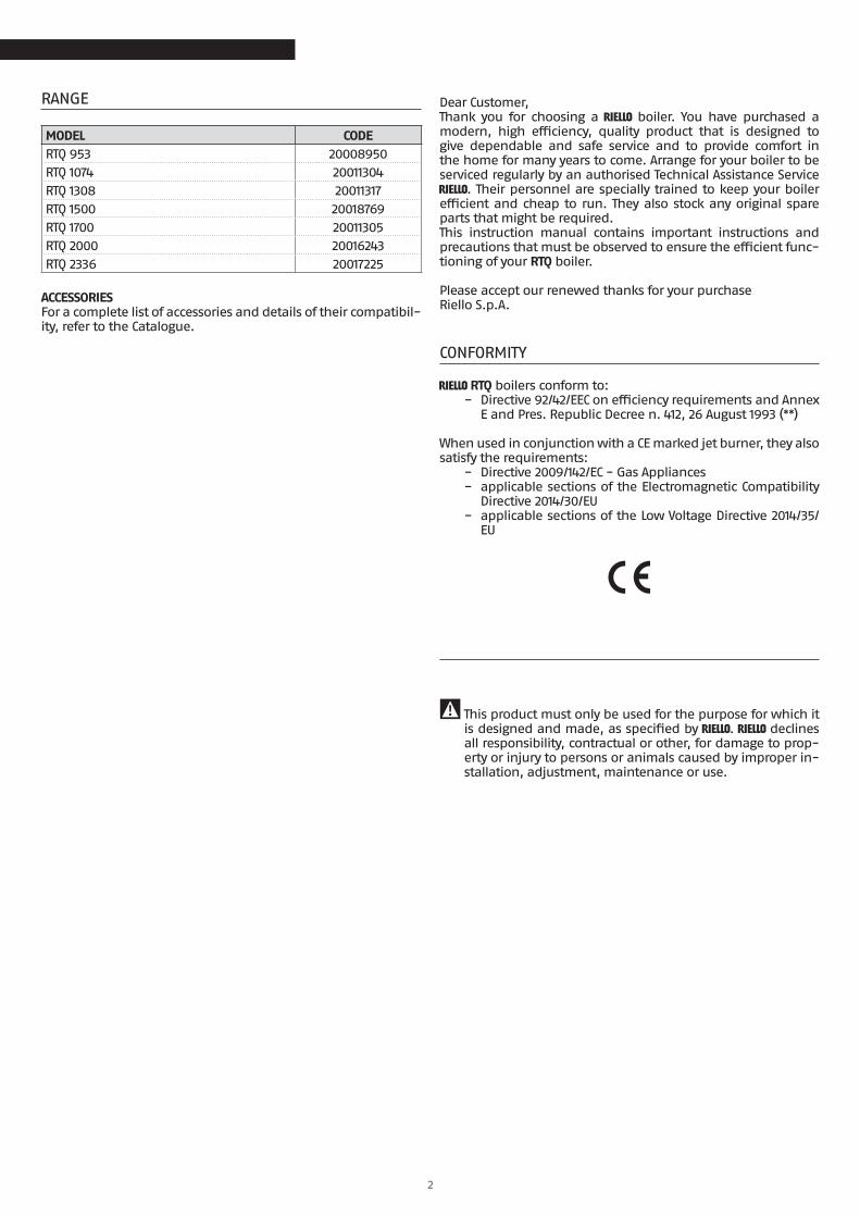
RANGE
MODEL CODERTQ 953 20008950RTQ 1074 20011304RTQ 1308 20011317RTQ 1500 20018769RTQ 1700 20011305RTQ 2000 20016243RTQ 2336 20017225
ACCESSORIESFor a complete list of accessories and details of their compatibil-ity, refer to the Catalogue.
ENGLISH
Dear Customer,Thank you for choosing a R boiler. You have purchased a modern, high efficiency, quality product that is designed to give dependable and safe service and to provide comfort in the home for many years to come. Arrange for your boiler to be serviced regularly by an authorised Technical Assistance Service R. Their personnel are specially trained to keep your boiler efficient and cheap to run. They also stock any original spare parts that might be required.This instruction manual contains important instructions and precautions that must be observed to ensure the efficient func-tioning of your RTQ boiler.
Please accept our renewed thanks for your purchaseRiello S.p.A.
CONFORMITY
R RTQ boilers conform to: − Directive 92/42/EEC on efficiency requirements and Annex
E and Pres. Republic Decree n. 412, 26 August 1993 (**)
When used in conjunction with a CE marked jet burner, they also satisfy the requirements:
− Directive 2009/142/EC - Gas Appliances − applicable sections of the Electromagnetic Compatibility
Directive 2014/30/EU − applicable sections of the Low Voltage Directive 2014/35/
EU
9 This product must only be used for the purpose for which it is designed and made, as specified by R. R declines all responsibility, contractual or other, for damage to prop-erty or injury to persons or animals caused by improper in-stallation, adjustment, maintenance or use.
3
This manual, Code 20017904 - Rev. 20 (09/2016) comprises 28 pages.
ContentsCONTENTS
The following symbols are used in this manual:
9 CAUTION! = Identifies actions that require caution and adequate preparation.
0 STOP! = Identifies actions that you MUST NOT do.
This manual, Code- Rev.comprisespages.
1 GENERAL INFORMATION . . . . . . . . . . . . . . . . . . . . . . . . . . . . 41.1 General Safety Information . . . . . . . . . . . . . . . . . . . . . . 41.2 Precautions. . . . . . . . . . . . . . . . . . . . . . . . . . . . . . . . . . 41.3 Description of the appliance . . . . . . . . . . . . . . . . . . . . . 41.4 Control panels. . . . . . . . . . . . . . . . . . . . . . . . . . . . . . . . 51.5 Recommended burners . . . . . . . . . . . . . . . . . . . . . . . .61.6 Identification . . . . . . . . . . . . . . . . . . . . . . . . . . . . . . . .81.7 Technical specifications. . . . . . . . . . . . . . . . . . . . . . . . .8
2 INSTALLATION . . . . . . . . . . . . . . . . . . . . . . . . . . . . . . . . . . . . . . 92.1 Unpacking the product . . . . . . . . . . . . . . . . . . . . . . . . .92.2 Overall dimensions and weights . . . . . . . . . . . . . . . . . 102.3 Handling. . . . . . . . . . . . . . . . . . . . . . . . . . . . . . . . . . . 102.4 Place of installation . . . . . . . . . . . . . . . . . . . . . . . . . . .112.6 Water connections . . . . . . . . . . . . . . . . . . . . . . . . . . . .112.5 Installation in older systems and systems requiring
modernisation . . . . . . . . . . . . . . . . . . . . . . . . . . . . . . .112.7 Anti-condensate pump. . . . . . . . . . . . . . . . . . . . . . . . 122.8 Hoses should also be fixed to the floor and suitably
protected whenever possible . . . . . . . . . . . . . . . . . . . 132.9 Door hinges . . . . . . . . . . . . . . . . . . . . . . . . . . . . . . . . 132.10 Changing the direction of door opening . . . . . . . . . . . 142.11 Fitting the insulation and turbulators . . . . . . . . . . . . . 162.12 Earth connection . . . . . . . . . . . . . . . . . . . . . . . . . . . . 182.13 Fitting the casing panels. . . . . . . . . . . . . . . . . . . . . . . 182.14 Preparing for initial startup. . . . . . . . . . . . . . . . . . . . . 192.15 Initial startup . . . . . . . . . . . . . . . . . . . . . . . . . . . . . . . 192.16 Checks during and after initial start-up . . . . . . . . . . . 202.17 Maintenance. . . . . . . . . . . . . . . . . . . . . . . . . . . . . . . . 212.18 Cleaning the boiler . . . . . . . . . . . . . . . . . . . . . . . . . . . 222.19 Troubleshooting . . . . . . . . . . . . . . . . . . . . . . . . . . . . . 23
3 USE . . . . . . . . . . . . . . . . . . . . . . . . . . . . . . . . . . . . . . . . . . . . . . . .243.1 Putting into service . . . . . . . . . . . . . . . . . . . . . . . . . . . 243.2 Temporary shutdown . . . . . . . . . . . . . . . . . . . . . . . . . 253.3 Preparing for extended periods of disuse . . . . . . . . . . 253.4 Cleaning . . . . . . . . . . . . . . . . . . . . . . . . . . . . . . . . . . . 253.5 Maintenance. . . . . . . . . . . . . . . . . . . . . . . . . . . . . . . . 263.6 Useful information . . . . . . . . . . . . . . . . . . . . . . . . . . . 27
4
GENERAL INFORMATION
GENERAL INFORMATION
1 GENERAL INFORMATION
1.1 General Safety Information
9 The boiler is delivered in separate crates. Check that it is complete, undamaged and as ordered as soon as you re-ceive it. Report any discrepancies or damage to the dealer who sold it.
9 This product must be installed by a legally qualified heat-ing engineer. On completion of the installation, the install-er must issue the owner with a declaration of conformity confirming that the installation has been completed to the highest standards in compliance with the instructions pro-vided by R in this instruction manual, and that it con-forms to all applicable laws and standards.
9 This product must only be used for the purpose for which it is designed and made, as specified by R. R declines all responsibility, contractual or other, for damage to prop-erty or injury to persons or animals caused by improper in-stallation, adjustment, maintenance or use.
9 If you notice any water leaking from the boiler, disconnect it immediately from the mains electricity supply, shut off the water supply, and notify your local R’s Technical Assis-tance Service or a qualified heating engineer immediately.
9 Periodically check that operating pressure in the water cir-cuit is over 1 bar but below the maximum limit specified for the boiler. If this is not the case, contact Technical Assistance Service R or a professionally qualified heating engineer.
9 If the boiler is not going to be used for an extended pe-riod of time, contact R’s Technical Assistance Service or a qualified heating engineer to have it prepared for shut-down as follows − Switch the boiler OFF at the control panel − Turn the main system switch "off" − Close the fuel cock and heating circuit water cock − Drain the central heating circuit if there is any risk of
freezing.
9 The boiler must be serviced at least once a year.
9 This instruction manual is an integral part of the boiler. It must be kept safe and must ALWAYS accompany the boiler, even if it is sold to another owner or transferred to another user or to another installation. If you damage or lose this manual, order a replacement immediately from your local R’s Technical Assistance Service.
1.2 Precautions
The operation of any appliance that uses fuel, electrical power and water demands that a number of fundamental safety pre-cautions be respected:
0 It is forbidden to use electrical devices or equipment, such as switches, appliances, etc. if there is a smell of gas or un-burnt products. If so: − Ventilate the room, opening doors and windows − Close the fuel shut-off cock − Report the fault immediately to the R's Technical As-
sistance Service or a professionally qualified heating en-gineer.
0 Do not touch the boiler while barefoot or wet.
0 Never clean or service the boiler without first disconnect-ing it from the mains electricity supply by turning the main power switch and the control panel switch OFF.
0 Do not tamper with or adjust the safety or control devices without prior authorisation and instructions from the man-ufacturer.
0 Do not plug or block the condensate drain outlet.
0 Never pull, disconnect, or twist the electrical cables coming from the appliance even if it is disconnected from the mains electricity supply.
0 Do not obstruct or restrict the vents in the room where the boiler is installed. Adequate ventilation is essential for cor-rect combustion.
0 Do not expose the boiler to the elements. It is designed to work indoors.
0 Do not switch the boiler off if outdoor temperature drops below ZERO (risk of freezing).
0 Do not store containers of flammable substances in the room where the boiler is installed.
0 Do not allow children or persons with reduced physical, sensorial or mental abilities or with insufficient experience and knowledge to operate this system without proper su-pervision from the person responsible for its safe use.
0 Do not dispose of packaging material into the environment, or leave it within the reach of children, since it can become a potential hazard. Dispose of packaging material in com-pliance with applicable legislation.
1.3 Description of the appliance
R RTQ steel boilers are high efficiency boilers with horizon-tal, flame reversal combustion chambers and concentrically arranged flue gas pipes. They are designed for central heating and, when used in conjunction with a suitable storage cylinder, for domestic hot water production too.Because they operate at low pressure, they provide a gradual heating action without thermal shock.
The most important technical features of these boilers are: − The combustion chamber and heat exchange system are
specially designed and shaped to achieve the best pos-sible volume ratio;
− Only top quality materials are used to ensure a long working life.
Stainless steel turbulators inside the flue gas pipes establish an ideal pressure inside the combustion chamber and an ideal flue gas temperature. Evenly distributed thermal load optimises the efficiency of the boiler-burner system.The boiler body is thoroughly insulated with a layer of high den-sity glass wool.The boiler’s front door and the flue gas box can be opened com-pletely to facilitate the inspection, maintenance and cleaning of internal parts and to speed up servicing in general.The front door can open in either direction, even without re-moving the burner.
General information
5
GENERAL INFORMATION
GENERAL INFORMATION
0
30
60 90
3
2
1
12
4 6 7 85
13
14
10
9
11
15
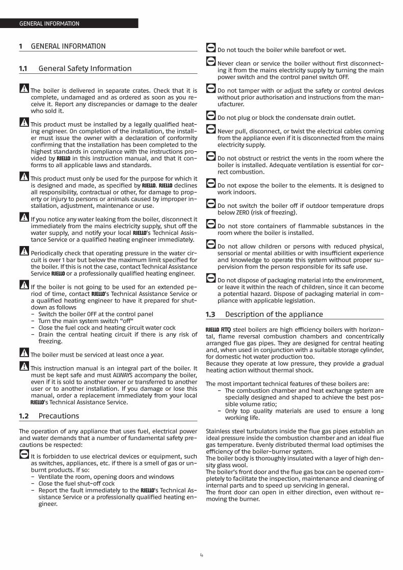
1 Burner2 Flame inspection window with pressure meas-
urement / cooling valve3 Door4 Casing5 Central heating return6 Safety device fitting7 Instrument bulb/sensor sockets8 Central heating flow9 Flue gas pipes
10 Turbulators11 Combustion chamber12 Flue gas exhaust13 Flue gas box14 Inspection window15 Condensate outlet
1.4 Control panels
The R control panels that can be used with R RTQ steel boilers are listed below. These control panels cater for all the needs of the heating system and of all the devices installed in it.
TECH CLIMA TOP for central heating (1 direct zone and 2 mixed zones) and domestic hot water production with a single stage, two stage, or modulating burner. Also for controlling solar heat-ing system and cascaded boiler systems.
TECH PRIME for central heating only (1 direct zone) with a single or two stage burner.
TECH CLIMA COMFORT for central heating (1 direct zone and 1 mixed zone) and domestic hot water production with a single stage burner. Also for controlling solar heating system and cas-caded boiler systems.
TECH PRIME ACS for central heating (1 direct zone) and domestic hot water production with a single or two stage burner.
0When a TECH CLIMA TOP or CLIMA COMFORT control panel is in-stalled, the boiler return (cold) line must be equipped with a temperature sensor socket. See the Catalogue for the nec-essary accessory part numbers.
6
GENERAL INFORMATION
GENERAL INFORMATION
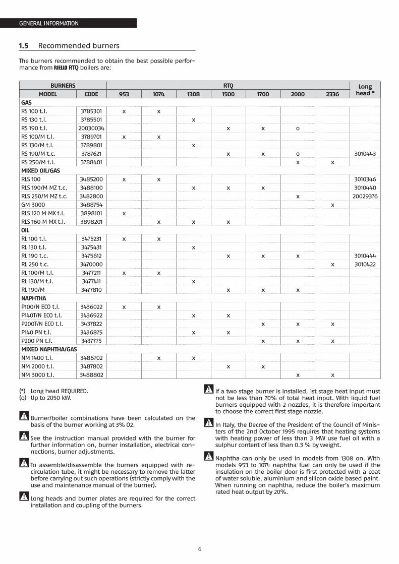
1.5 Recommended burners
The burners recommended to obtain the best possible perfor-mance from R RTQ boilers are:
BURNERS RTQ Long head *MODEL CODE 953 1074 1308 1500 1700 2000 2336
GASRS 100 t.l. 3785301 x xRS 130 t.l. 3785501 xRS 190 t.l. 20030034 x x oRS 100/M t.l. 3789701 x xRS 130/M t.l. 3789801 xRS 190/M t.c. 3787621 x x o 3010443RS 250/M t.l. 3788401 x xMIXED OIL/GASRLS 100 3485200 x x 3010346RLS 190/M MZ t.c. 3488100 x x x 3010440RLS 250/M MZ t.c. 3482800 x 20029376GM 3000 3488754 xRLS 120 M MX t.l. 3898101 xRLS 160 M MX t.l. 3898201 x x xOILRL 100 t.l. 3475231 x xRL 130 t.l. 3475431 xRL 190 t.c. 3475612 x x x 3010444RL 250 t.c. 3470000 x 3010422RL 100/M t.l. 3477211 x xRL 130/M t.l. 3477411 xRL 190/M 3477810 x x xNAPHTHAP100/N ECO t.l. 3436022 x xP140T/N ECO t.l. 3436922 x xP200T/N ECO t.l. 3437822 x x xP140 PN t.l. 3436875 x xP200 PN t.l. 3437775 x x xMIXED NAPHTHA/GASNM 1400 t.l. 3486702 x xNM 2000 t.l. 3487802 x xNM 3000 t.l. 3488802 x x
(*) Long head REQUIRED.(o) Up to 2050 kW.
9 Burner/boiler combinations have been calculated on the basis of the burner working at 3% O2.
9 See the instruction manual provided with the burner for further information on, burner installation, electrical con-nections, burner adjustments.
9 To assemble/disassemble the burners equipped with re-circulation tube, it might be necessary to remove the latter before carrying out such operations (strictly comply with the use and maintenance manual of the burner).
9 Long heads and burner plates are required for the correct installation and coupling of the burners.
9 If a two stage burner is installed, 1st stage heat input must not be less than 70% of total heat input. With liquid fuel burners equipped with 2 nozzles, it is therefore important to choose the correct first stage nozzle.
9 In Italy, the Decree of the President of the Council of Minis-ters of the 2nd October 1995 requires that heating systems with heating power of less than 3 MW use fuel oil with a sulphur content of less than 0.3 % by weight.
9 Naphtha can only be used in models from 1308 on. With models 953 to 1074 naphtha fuel can only be used if the insulation on the boiler door is first protected with a coat of water soluble, aluminium and silicon oxide based paint. When running on naphtha, reduce the boiler’s maximum rated heat output by 20%.
7
GENERAL INFORMATION
GENERAL INFORMATION
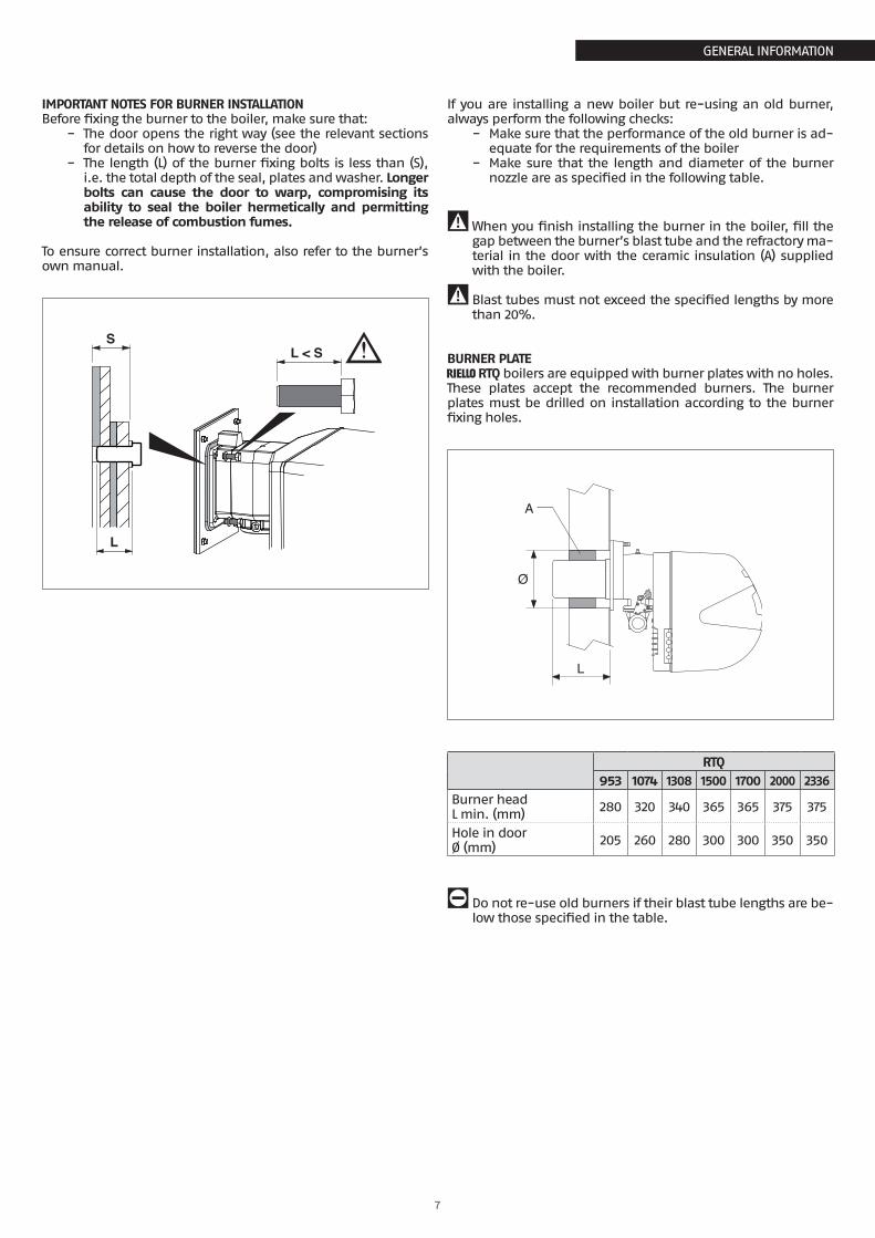
IMPORTANT NOTES FOR BURNER INSTALLATIONBefore fixing the burner to the boiler, make sure that:
− The door opens the right way (see the relevant sections for details on how to reverse the door)
− The length (L) of the burner fixing bolts is less than (S), i.e. the total depth of the seal, plates and washer. Longer bolts can cause the door to warp, compromising its ability to seal the boiler hermetically and permitting the release of combustion fumes.
To ensure correct burner installation, also refer to the burner’s own manual.
L < SS
L
If you are installing a new boiler but re-using an old burner, always perform the following checks:
− Make sure that the performance of the old burner is ad-equate for the requirements of the boiler
− Make sure that the length and diameter of the burner nozzle are as specified in the following table.
9When you finish installing the burner in the boiler, fill the gap between the burner’s blast tube and the refractory ma-terial in the door with the ceramic insulation (A) supplied with the boiler.
9 Blast tubes must not exceed the specified lengths by more than 20%.
BURNER PLATER RTQ boilers are equipped with burner plates with no holes. These plates accept the recommended burners. The burner plates must be drilled on installation according to the burner fixing holes.
A
Ø
L
RTQ953 1074 1308 1500 1700 2000 2336
Burner headL min. (mm) 280 320 340 365 365 375 375
Hole in doorØ (mm) 205 260 280 300 300 350 350
0 Do not re-use old burners if their blast tube lengths are be-low those specified in the table.
8
GENERAL INFORMATION
GENERAL INFORMATION
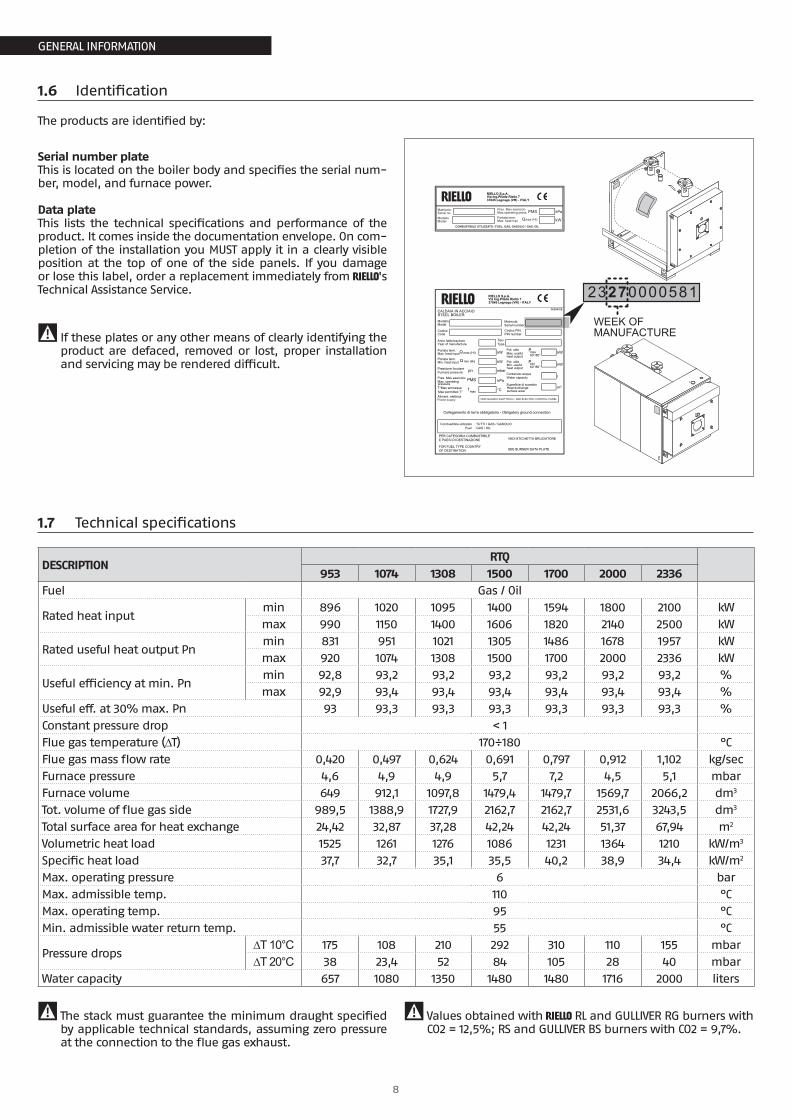
1.6 Identification
The products are identified by:
Serial number plateThis is located on the boiler body and specifies the serial num-ber, model, and furnace power.
Data plateThis lists the technical specifications and performance of the product. It comes inside the documentation envelope. On com-pletion of the installation you MUST apply it in a clearly visible position at the top of one of the side panels. If you damage or lose this label, order a replacement immediately from R's Technical Assistance Service.
9 If these plates or any other means of clearly identifying the product are defaced, removed or lost, proper installation and servicing may be rendered difficult.
CALDAIA IN ACCIAIO
Modello Matricola
CodiceCode
Anno fabbricazione TipoType
Portata term. Pot. utile
Pres. Max esercizio
Aliment. elettrica
kW
T°Max ammessa
Contenuto acqua
°C
l
Combustibile utilizzato : TUTTI I GAS / GASOLIO
max (Hi)Q max 60°/80°P
PMS
Pressione focolare
kW
pn
PER CATEGORIA COMBUSTIBILEE PAESI DI DESTINAZIONE VEDI ETICHETTA BRUCIATORE
Portata term.min (Hi)Q kW Pot. utile
kW
Tmaxm²
Superficie di scambio
mbar
RIELLO S.p.A.Via Ing.Pilade Riello 737045 Legnago (VR) - ITALY
066940IE
STEEL BOILER
Model Serial numberCodice PINPIN number
Year of manufacture
Max. heat input
Min. heat input
Furnace pressure
Max. operating pressure
T°Max permitted
Max. usefulheat output
60°/80°Pmin
heat outputMin. useful
Water capacity
Heat exchangesurface area
VEDI QUADRO ELETTRICO - SEE ELECTRIC CONTROL PANEL
Collegamento di terra obbligatorio - Obligatory ground connection
Fuel : GAS / OIL
FOR FUEL TYPE COUNTRYOF DESTINATION SEE BURNER DATA PLATE
Power supply
Pak
Matricola
Modello
Pres. Max esercizio
Portata term. Qmax (Hi)
PMS
kW
RIELLO S.p.A.Via Ing.Pilade Riello 737045 Legnago (VR) - ITALY
Serial no.
Model
Max.operating press.
Max. heat inpt
COMBUSTIBILE UTILIZZATO / FUEL: GAS, GASOLIO / GAS, OIL
Pak
23270000581
WEEK OFMANUFACTURE
1.7 Technical specifications
DESCRIPTIONRTQ
953 1074 1308 1500 1700 2000 2336Fuel Gas / Oil
Rated heat inputmin 896 1020 1095 1400 1594 1800 2100 kWmax 990 1150 1400 1606 1820 2140 2500 kW
Rated useful heat output Pnmin 831 951 1021 1305 1486 1678 1957 kWmax 920 1074 1308 1500 1700 2000 2336 kW
Useful efficiency at min. Pnmin 92,8 93,2 93,2 93,2 93,2 93,2 93,2 %max 92,9 93,4 93,4 93,4 93,4 93,4 93,4 %
Useful eff. at 30% max. Pn 93 93,3 93,3 93,3 93,3 93,3 93,3 %Constant pressure drop < 1Flue gas temperature (∆T) 170÷180 °CFlue gas mass flow rate 0,420 0,497 0,624 0,691 0,797 0,912 1,102 kg/secFurnace pressure 4,6 4,9 4,9 5,7 7,2 4,5 5,1 mbarFurnace volume 649 912,1 1097,8 1479,4 1479,7 1569,7 2066,2 dm3
Tot. volume of flue gas side 989,5 1388,9 1727,9 2162,7 2162,7 2531,6 3243,5 dm3
Total surface area for heat exchange 24,42 32,87 37,28 42,24 42,24 51,37 67,94 m2
Volumetric heat load 1525 1261 1276 1086 1231 1364 1210 kW/m3
Specific heat load 37,7 32,7 35,1 35,5 40,2 38,9 34,4 kW/m2
Max. operating pressure 6 barMax. admissible temp. 110 °CMax. operating temp. 95 °CMin. admissible water return temp. 55 °C
Pressure drops∆T 10°C 175 108 210 292 310 110 155 mbar∆T 20°C 38 23,4 52 84 105 28 40 mbar
Water capacity 657 1080 1350 1480 1480 1716 2000 liters
9 The stack must guarantee the minimum draught specified by applicable technical standards, assuming zero pressure at the connection to the flue gas exhaust.
9 Values obtained with R RL and GULLIVER RG burners with CO2 = 12,5%; RS and GULLIVER BS burners with CO2 = 9,7%.

9
INSTALLATION
INSTALLATION
2 INSTALLATION
2.1 Unpacking the product
R RTQ steel boilers come in 2 separate crates:1 BOILER BODY CRATE to which is attached the documentation
envelope (A) containing: − Instruction manual; − Data label (to be applied to the casing on completion of
the installation); − Certificate of Warranty and water test certificate; − Bar code labels; − Spare parts catalogue.
A
9 The following material, to be fitted by the installer, is locat-ed inside the combustion chamber: − turbulators and turbulator fixing clips (for installation in
the flue gas pipes); − water connection flanges; − boiler body insulation and fasteners.
For fitting instructions, see the section entitled "Fitting the insulation and turbulators" on page 16.
MATERIALSUPPLIED
9 The instruction manual is an integral part of the boiler. Once located, read it thoroughly and keep it safe.
2 THE CASING PANELS complete with assembly accessories (2 packs).
IMPORTANTFor the boiler to function correctly, it must be connected to a R TECH control panel and dedicated control accessories.
Installation
10
INSTALLATION
INSTALLATION
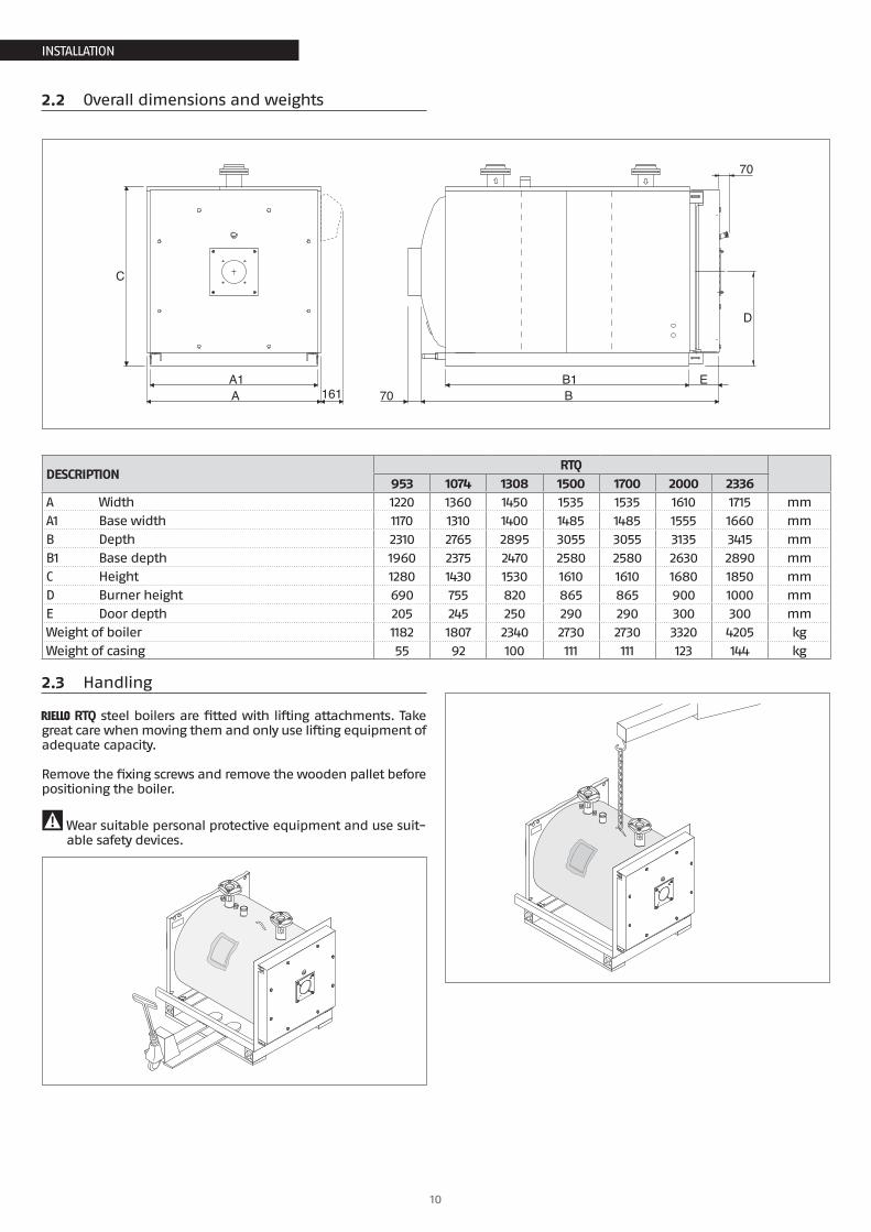
2.2 Overall dimensions and weights
C
AA1
BB1 E
D
70
70
161
DESCRIPTIONRTQ
953 1074 1308 1500 1700 2000 2336A Width 1220 1360 1450 1535 1535 1610 1715 mmA1 Base width 1170 1310 1400 1485 1485 1555 1660 mmB Depth 2310 2765 2895 3055 3055 3135 3415 mmB1 Base depth 1960 2375 2470 2580 2580 2630 2890 mmC Height 1280 1430 1530 1610 1610 1680 1850 mmD Burner height 690 755 820 865 865 900 1000 mmE Door depth 205 245 250 290 290 300 300 mmWeight of boiler 1182 1807 2340 2730 2730 3320 4205 kgWeight of casing 55 92 100 111 111 123 144 kg
2.3 Handling
R RTQ steel boilers are fitted with lifting attachments. Take great care when moving them and only use lifting equipment of adequate capacity.
Remove the fixing screws and remove the wooden pallet before positioning the boiler.
9Wear suitable personal protective equipment and use suit-able safety devices.
11
INSTALLATION
INSTALLATION
2.4 Place of installation
R RTQ steel boilers must be installed in a dedicated boiler room, with adequately sized vents, in compliance with applica-ble laws and standards.
If at all possible, the boiler should be installed on a raised base to prevent the burner fan sucking up dust.
9When installing the boiler, allow sufficient space around it to access all safety and control devices and to permit easy maintenance.
9 If the specific weight of the gas supply to the burner is greater than the specific weight of air, install all electrical parts at least 500 mm above floor level.
0 Do not install the boiler outdoors. It is not designed to work outdoors and is not fitted with the necessary automatic an-ti-frost systems to do so.
2.5 Installation in older systems and systems requiring modernisation
When installing these boilers in old systems or systems requiring modernisation, always perform the following checks:
− make sure that the stack is able to withstand the tempera-ture of the combustion gases and that it has been designed and made in compliance with applicable standards. The stack must also be as straight as possible, sealed, insulated and not blocked or choked;
− make sure that the electrical system has been installed by a qualified electrician in compliance with applicable stand-ards;
− make sure that the oil feed line and any oil storage tank are made and installed in compliance with applicable stand-ards;
− make sure that the expansion vessels are big enough to contain the volume generated by thermal expansion;
− make sure that flow rate, head and direction of flow of the pumps are suitable and correct;
− make sure that the circuit has been flushed out to remove all sludge and lime scale, and has been vented and seal tested.
− make sure that a suitable water treatment system is installed if the quality of the supply/recirculation water so demands.
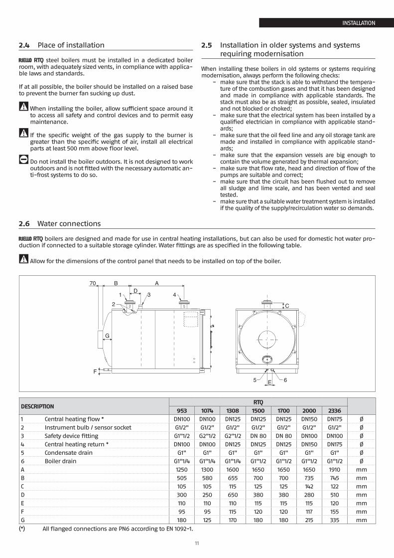
2.6 Water connections
R RTQ boilers are designed and made for use in central heating installations, but can also be used for domestic hot water pro-duction if connected to a suitable storage cylinder. Water fittings are as specified in the following table.
9 Allow for the dimensions of the control panel that needs to be installed on top of the boiler.
AB70
1 43
C2
5 6
D
F
E
G
DESCRIPTIONRTQ
953 1074 1308 1500 1700 2000 23361 Central heating flow * DN100 DN100 DN125 DN125 DN125 DN150 DN175 Ø2 Instrument bulb / sensor socket G1/2" G1/2" G1/2" G1/2" G1/2" G1/2" G1/2" Ø3 Safety device fitting G1"1/2 G2"1/2 G2"1/2 DN 80 DN 80 DN100 DN100 Ø4 Central heating return * DN100 DN100 DN125 DN125 DN125 DN150 DN175 Ø5 Condensate drain G1" G1" G1" G1" G1" G1" G1" Ø6 Boiler drain G1"1/4 G1"1/4 G1"1/4 G1"1/2 G1"1/2 G1"1/2 G1"1/2 ØA 1250 1300 1600 1650 1650 1650 1910 mmB 505 580 655 700 700 735 745 mmC 105 105 115 125 125 142 122 mmD 300 250 650 380 380 280 510 mmE 110 110 110 115 115 115 120 mmF 95 95 115 120 120 117 155 mmG 180 125 170 180 180 215 335 mm
(*) All flanged connections are PN6 according to EN 1092-1.
12
INSTALLATION
INSTALLATION
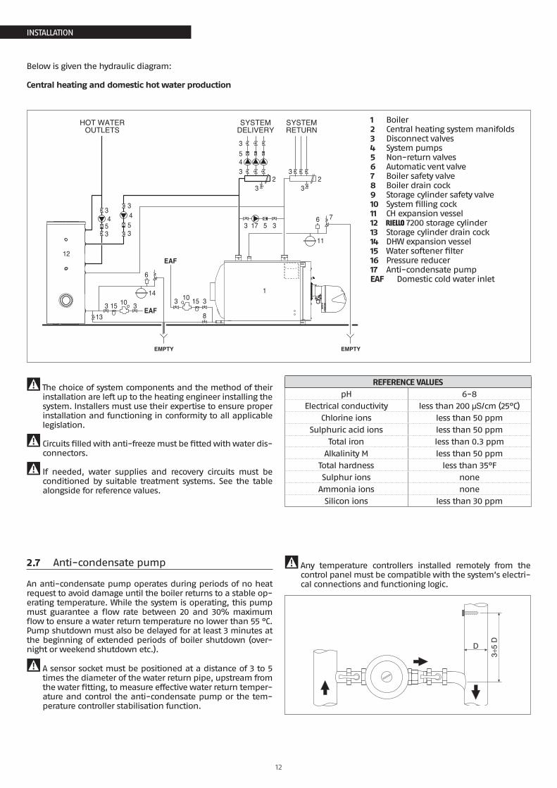
Below is given the hydraulic diagram:
Central heating and domestic hot water production
32 2
3
33453
8
10 1510
13
14
12
1
EAF
EAF15
6
33
3 3
11
6 717 5
33
35
34
35
34
HOT WATEROUTLETS
EMPTY EMPTY
SYSTEMDELIVERY
SYSTEMRETURN
1 Boiler2 Central heating system manifolds3 Disconnect valves4 System pumps5 Non-return valves6 Automatic vent valve7 Boiler safety valve8 Boiler drain cock9 Storage cylinder safety valve10 System filling cock11 CH expansion vessel12 R 7200 storage cylinder13 Storage cylinder drain cock14 DHW expansion vessel15 Water softener filter16 Pressure reducer17 Anti-condensate pumpEAF Domestic cold water inlet
9 The choice of system components and the method of their installation are left up to the heating engineer installing the system. Installers must use their expertise to ensure proper installation and functioning in conformity to all applicable legislation.
9 Circuits filled with anti-freeze must be fitted with water dis-connectors.
9 If needed, water supplies and recovery circuits must be conditioned by suitable treatment systems. See the table alongside for reference values.
REFERENCE VALUESpH 6-8
Electrical conductivity less than 200 μS/cm (25°C)Chlorine ions less than 50 ppm
Sulphuric acid ions less than 50 ppmTotal iron less than 0.3 ppm
Alkalinity M less than 50 ppmTotal hardness less than 35°FSulphur ions none
Ammonia ions noneSilicon ions less than 30 ppm
2.7 Anti-condensate pump
An anti-condensate pump operates during periods of no heat request to avoid damage until the boiler returns to a stable op-erating temperature. While the system is operating, this pump must guarantee a flow rate between 20 and 30% maximum flow to ensure a water return temperature no lower than 55 °C. Pump shutdown must also be delayed for at least 3 minutes at the beginning of extended periods of boiler shutdown (over-night or weekend shutdown etc.).
9 A sensor socket must be positioned at a distance of 3 to 5 times the diameter of the water return pipe, upstream from the water fitting, to measure effective water return temper-ature and control the anti-condensate pump or the tem-perature controller stabilisation function.
9 Any temperature controllers installed remotely from the control panel must be compatible with the system’s electri-cal connections and functioning logic.
D
3÷5
D
13
INSTALLATION
INSTALLATION
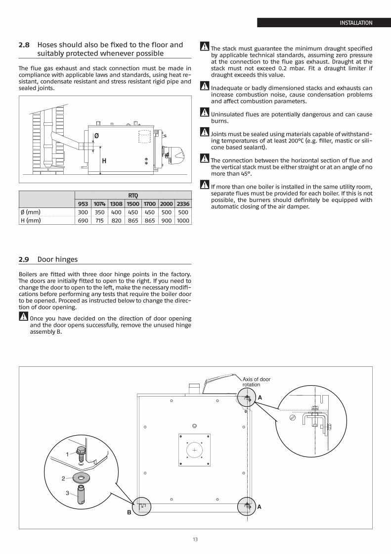
2.8 Hoses should also be fixed to the floor and suitably protected whenever possible
The flue gas exhaust and stack connection must be made in compliance with applicable laws and standards, using heat re-sistant, condensate resistant and stress resistant rigid pipe and sealed joints.
H0
30
6090
Ø
RTQ953 1074 1308 1500 1700 2000 2336
Ø (mm) 300 350 400 450 450 500 500H (mm) 690 715 820 865 865 900 1000
9 The stack must guarantee the minimum draught specified by applicable technical standards, assuming zero pressure at the connection to the flue gas exhaust. Draught at the stack must not exceed 0.2 mbar. Fit a draught limiter if draught exceeds this value.
9 Inadequate or badly dimensioned stacks and exhausts can increase combustion noise, cause condensation problems and affect combustion parameters.
9 Uninsulated flues are potentially dangerous and can cause burns.
9 Joints must be sealed using materials capable of withstand-ing temperatures of at least 200°C (e.g. filler, mastic or sili-cone based sealant).
9 The connection between the horizontal section of flue and the vertical stack must be either straight or at an angle of no more than 45°.
9 If more than one boiler is installed in the same utility room, separate flues must be provided for each boiler. If this is not possible, the burners should definitely be equipped with automatic closing of the air damper.
2.9 Door hinges
Boilers are fitted with three door hinge points in the factory. The doors are initially fitted to open to the right. If you need to change the door to open to the left, make the necessary modifi-cations before performing any tests that require the boiler door to be opened. Proceed as instructed below to change the direc-tion of door opening.
9 Once you have decided on the direction of door opening and the door opens successfully, remove the unused hinge assembly B.
Axis of doorrotation
A
AB
1
2
3
14
INSTALLATION
INSTALLATION
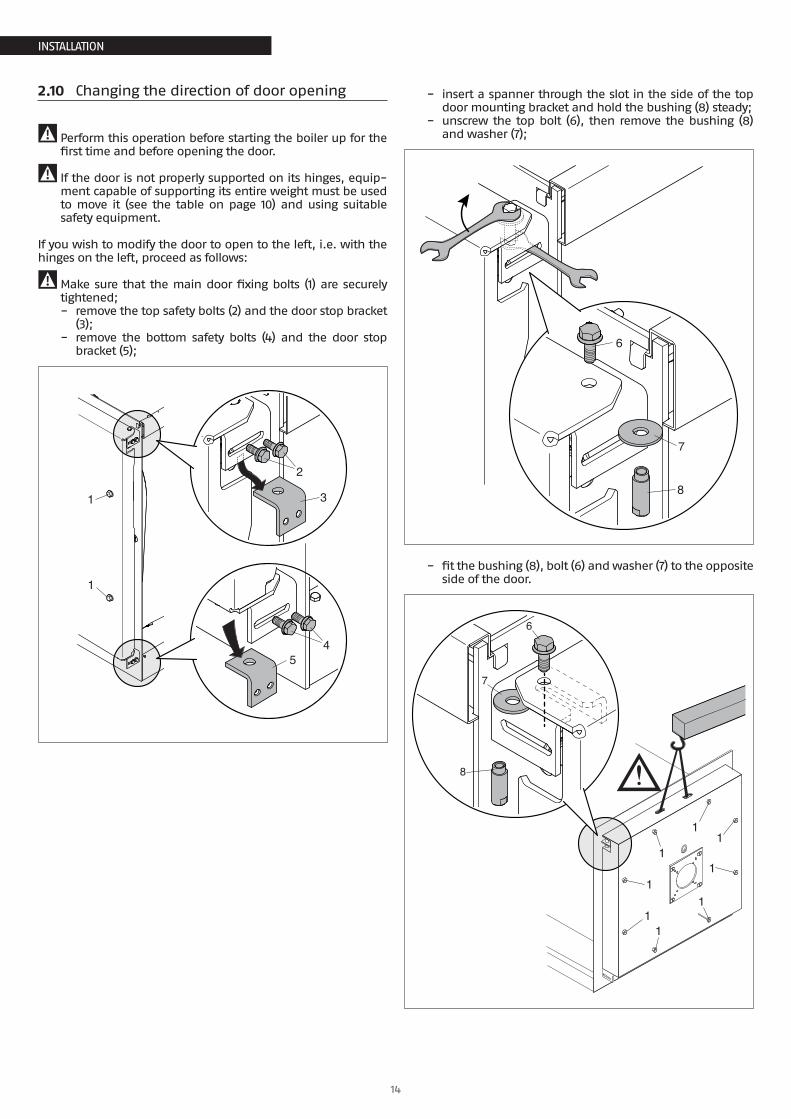
2.10 Changing the direction of door opening
9 Perform this operation before starting the boiler up for the first time and before opening the door.
9 If the door is not properly supported on its hinges, equip-ment capable of supporting its entire weight must be used to move it (see the table on page 10) and using suitable safety equipment.
If you wish to modify the door to open to the left, i.e. with the hinges on the left, proceed as follows:
9Make sure that the main door fixing bolts (1) are securely tightened; − remove the top safety bolts (2) and the door stop bracket
(3); − remove the bottom safety bolts (4) and the door stop
bracket (5);
1
2
45
3
1
− insert a spanner through the slot in the side of the top door mounting bracket and hold the bushing (8) steady;
− unscrew the top bolt (6), then remove the bushing (8) and washer (7);
6
8
7
− fit the bushing (8), bolt (6) and washer (7) to the opposite side of the door.
11
11
11
1
1
6
8
7
15
INSTALLATION
INSTALLATION
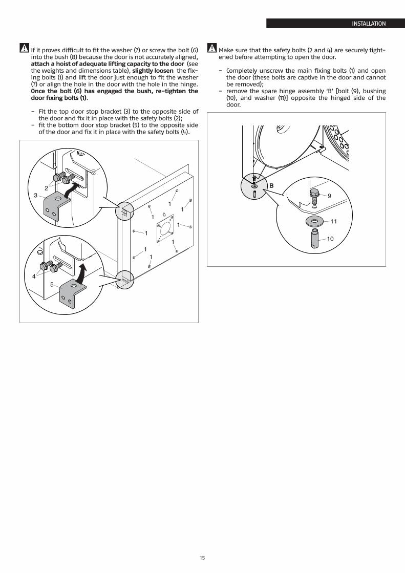
9 If it proves difficult to fit the washer (7) or screw the bolt (6) into the bush (8) because the door is not accurately aligned, attach a hoist of adequate lifting capacity to the door (see the weights and dimensions table), slightly loosen the fix-ing bolts (1) and lift the door just enough to fit the washer (7) or align the hole in the door with the hole in the hinge. Once the bolt (6) has engaged the bush, re-tighten the door fixing bolts (1).
− Fit the top door stop bracket (3) to the opposite side of the door and fix it in place with the safety bolts (2);
− fit the bottom door stop bracket (5) to the opposite side of the door and fix it in place with the safety bolts (4).
23
45
11
11
11
1
1
9Make sure that the safety bolts (2 and 4) are securely tight-ened before attempting to open the door.
− Completely unscrew the main fixing bolts (1) and open the door (these bolts are captive in the door and cannot be removed);
− remove the spare hinge assembly ‘B’ [bolt (9), bushing (10), and washer (11)] opposite the hinged side of the door.
9
11
10
B
16
INSTALLATION
INSTALLATION
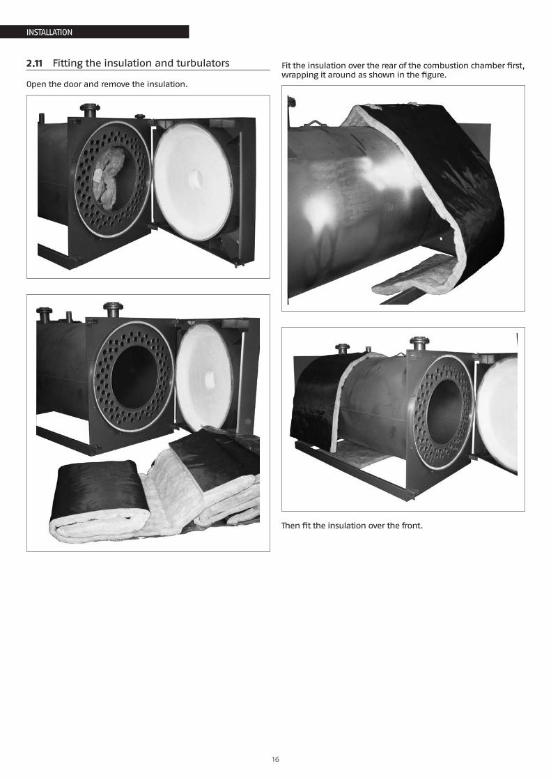
2.11 Fitting the insulation and turbulators
Open the door and remove the insulation.
Fit the insulation over the rear of the combustion chamber first, wrapping it around as shown in the figure.
Then fit the insulation over the front.
17
INSTALLATION
INSTALLATION
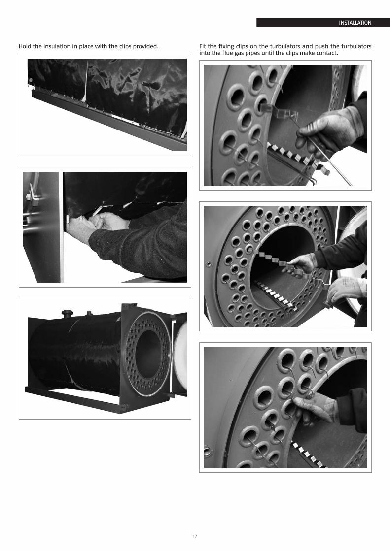
Hold the insulation in place with the clips provided. Fit the fixing clips on the turbulators and push the turbulators into the flue gas pipes until the clips make contact.
18
INSTALLATION
INSTALLATION
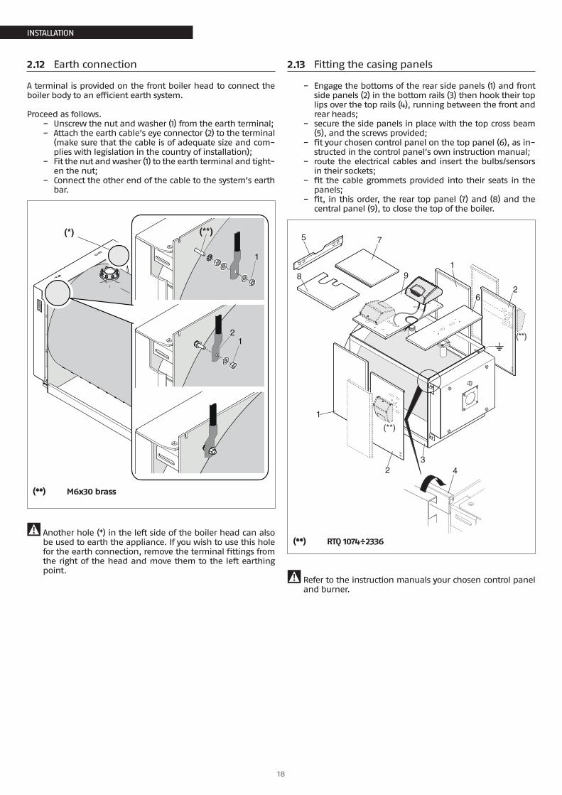
2.12 Earth connection
A terminal is provided on the front boiler head to connect the boiler body to an efficient earth system.
Proceed as follows. − Unscrew the nut and washer (1) from the earth terminal; − Attach the earth cable’s eye connector (2) to the terminal
(make sure that the cable is of adequate size and com-plies with legislation in the country of installation);
− Fit the nut and washer (1) to the earth terminal and tight-en the nut;
− Connect the other end of the cable to the system’s earth bar.
(*) (**)
1
21
(**) M6x30 brass
9 Another hole (*) in the left side of the boiler head can also be used to earth the appliance. If you wish to use this hole for the earth connection, remove the terminal fittings from the right of the head and move them to the left earthing point.
2.13 Fitting the casing panels
− Engage the bottoms of the rear side panels (1) and front side panels (2) in the bottom rails (3) then hook their top lips over the top rails (4), running between the front and rear heads;
− secure the side panels in place with the top cross beam (5), and the screws provided;
− fit your chosen control panel on the top panel (6), as in-structed in the control panel’s own instruction manual;
− route the electrical cables and insert the bulbs/sensors in their sockets;
− fit the cable grommets provided into their seats in the panels;
− fit, in this order, the rear top panel (7) and (8) and the central panel (9), to close the top of the boiler.
4
1
23
2
1
75
8
6
9
(**)
(**)
(**) RTQ 1074÷2336
9 Refer to the instruction manuals your chosen control panel and burner.
19
INSTALLATION
INSTALLATION
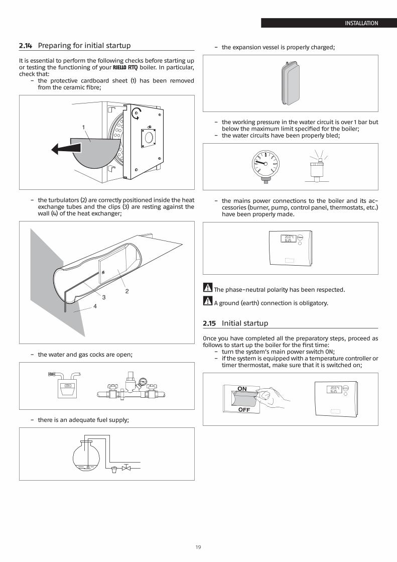
2.14 Preparing for initial startup
It is essential to perform the following checks before starting up or testing the functioning of your R RTQ boiler. In particular, check that:
− the protective cardboard sheet (1) has been removed from the ceramic fibre;
1
− the turbulators (2) are correctly positioned inside the heat exchange tubes and the clips (3) are resting against the wall (4) of the heat exchanger;
23
4
− the water and gas cocks are open;
− there is an adequate fuel supply;
− the expansion vessel is properly charged;
− the working pressure in the water circuit is over 1 bar but below the maximum limit specified for the boiler;
− the water circuits have been properly bled;
− the mains power connections to the boiler and its ac-cessories (burner, pump, control panel, thermostats, etc.) have been properly made.
9 The phase-neutral polarity has been respected.
9 A ground (earth) connection is obligatory.
2.15 Initial startup
Once you have completed all the preparatory steps, proceed as follows to start up the boiler for the first time:
− turn the system’s main power switch ON; − if the system is equipped with a temperature controller or
timer thermostat, make sure that it is switched on;
20
INSTALLATION
INSTALLATION
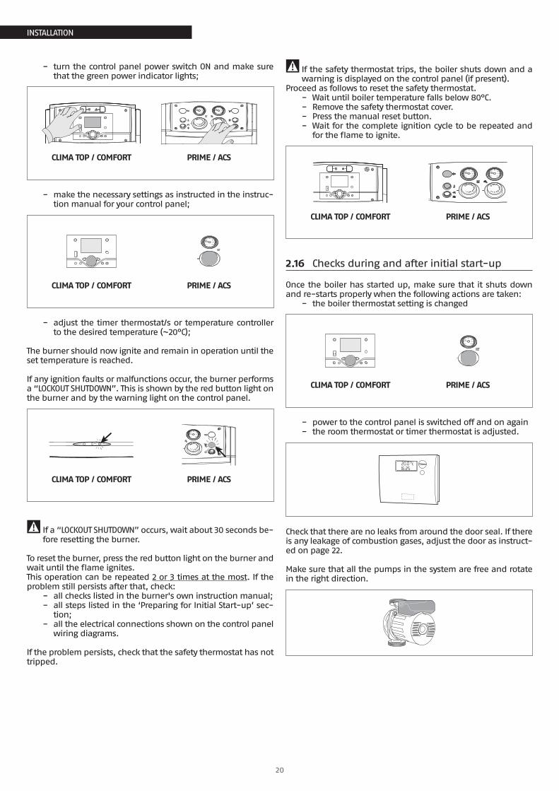
− turn the control panel power switch ON and make sure that the green power indicator lights;
20
4060
80
100
0 120
20
4060
80
100
0 120
CLIMA TOP / COMFORT PRIME / ACS
− make the necessary settings as instructed in the instruc-tion manual for your control panel;
20
4060
80
100
0 120
CLIMA TOP / COMFORT PRIME / ACS
− adjust the timer thermostat/s or temperature controller to the desired temperature (~20°C);
The burner should now ignite and remain in operation until the set temperature is reached.
If any ignition faults or malfunctions occur, the burner performs a “LOCKOUT SHUTDOWN”. This is shown by the red button light on the burner and by the warning light on the control panel.
20
4060
80
100
0 120
CLIMA TOP / COMFORT PRIME / ACS
9 If a “LOCKOUT SHUTDOWN” occurs, wait about 30 seconds be-fore resetting the burner.
To reset the burner, press the red button light on the burner and wait until the flame ignites.This operation can be repeated 2 or 3 times at the most. If the problem still persists after that, check:
− all checks listed in the burner's own instruction manual; − all steps listed in the ‘Preparing for Initial Start-up’ sec-
tion; − all the electrical connections shown on the control panel
wiring diagrams.
If the problem persists, check that the safety thermostat has not tripped.
9 If the safety thermostat trips, the boiler shuts down and a warning is displayed on the control panel (if present).
Proceed as follows to reset the safety thermostat. − Wait until boiler temperature falls below 80°C. − Remove the safety thermostat cover. − Press the manual reset button. − Wait for the complete ignition cycle to be repeated and
for the flame to ignite.
20
4060
80
100
0 120
20
4060
80
100
0 120
CLIMA TOP / COMFORT PRIME / ACS
2.16 Checks during and after initial start-up
Once the boiler has started up, make sure that it shuts down and re-starts properly when the following actions are taken:
− the boiler thermostat setting is changed
20
4060
80
100
0 120
CLIMA TOP / COMFORT PRIME / ACS
− power to the control panel is switched off and on again − the room thermostat or timer thermostat is adjusted.
Check that there are no leaks from around the door seal. If there is any leakage of combustion gases, adjust the door as instruct-ed on page 22.
Make sure that all the pumps in the system are free and rotate in the right direction.
21
INSTALLATION
INSTALLATION
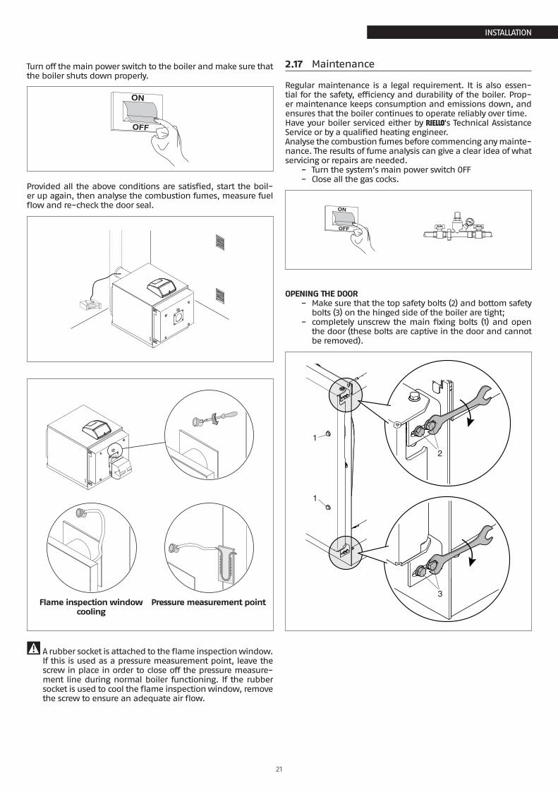
Turn off the main power switch to the boiler and make sure that the boiler shuts down properly.
Provided all the above conditions are satisfied, start the boil-er up again, then analyse the combustion fumes, measure fuel flow and re-check the door seal.
Flame inspection window cooling
Pressure measurement point
9 A rubber socket is attached to the flame inspection window. If this is used as a pressure measurement point, leave the screw in place in order to close off the pressure measure-ment line during normal boiler functioning. If the rubber socket is used to cool the flame inspection window, remove the screw to ensure an adequate air flow.
2.17 Maintenance
Regular maintenance is a legal requirement. It is also essen-tial for the safety, efficiency and durability of the boiler. Prop-er maintenance keeps consumption and emissions down, and ensures that the boiler continues to operate reliably over time.Have your boiler serviced either by R's Technical Assistance Service or by a qualified heating engineer.Analyse the combustion fumes before commencing any mainte-nance. The results of fume analysis can give a clear idea of what servicing or repairs are needed.
− Turn the system’s main power switch OFF − Close all the gas cocks.
OPENING THE DOOR − Make sure that the top safety bolts (2) and bottom safety
bolts (3) on the hinged side of the boiler are tight; − completely unscrew the main fixing bolts (1) and open
the door (these bolts are captive in the door and cannot be removed).
1
2
1
3
22
INSTALLATION
INSTALLATION
9Make sure that the door is properly adjusted after every maintenance operation.
ADJUSTING THE DOORMake quite sure that the door presses uniformly all around the double seal to prevent dangerous fumes escaping into the air from the pressurised furnace. Proceed as follows to adjust the door seals:
− push the door shut and tighten the main fixing bolts (1) until the seals start to compress;
− loosen the safety bolts (2 and 3) then fully tighten the main door fixing bolts (1);
− re-tighten the safety bolts (2 and 3).
9
11
10
B
9 The first time you open the door, remove the spare hinge assembly ‘B’ [bushing (10), bolt (9), and washer (11)] oppo-site the hinged side of the door.
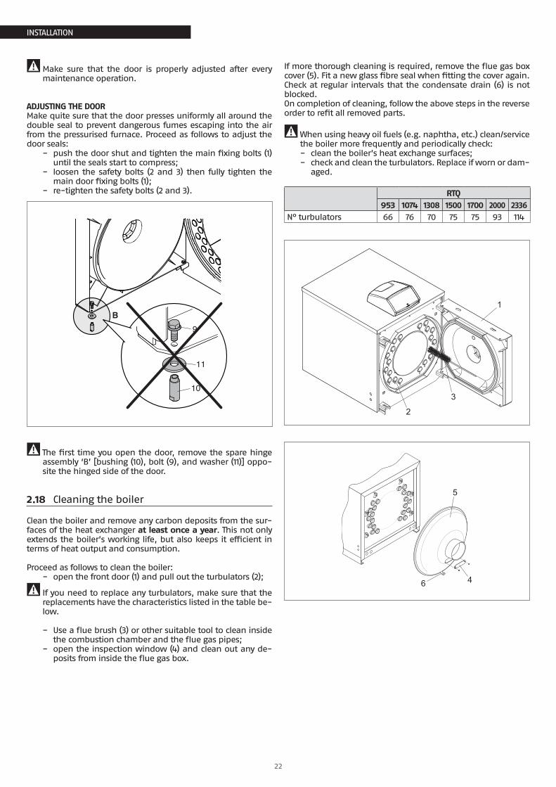
2.18 Cleaning the boiler
Clean the boiler and remove any carbon deposits from the sur-faces of the heat exchanger at least once a year. This not only extends the boiler’s working life, but also keeps it efficient in terms of heat output and consumption.
Proceed as follows to clean the boiler: − open the front door (1) and pull out the turbulators (2);
9 If you need to replace any turbulators, make sure that the replacements have the characteristics listed in the table be-low.
− Use a flue brush (3) or other suitable tool to clean inside the combustion chamber and the flue gas pipes;
− open the inspection window (4) and clean out any de-posits from inside the flue gas box.
If more thorough cleaning is required, remove the flue gas box cover (5). Fit a new glass fibre seal when fitting the cover again.Check at regular intervals that the condensate drain (6) is not blocked.On completion of cleaning, follow the above steps in the reverse order to refit all removed parts.
9When using heavy oil fuels (e.g. naphtha, etc.) clean/service the boiler more frequently and periodically check: − clean the boiler’s heat exchange surfaces; − check and clean the turbulators. Replace if worn or dam-
aged.
RTQ953 1074 1308 1500 1700 2000 2336
N° turbulators 66 76 70 75 75 93 114
1
2
3
5
6 4
23
INSTALLATION
INSTALLATION
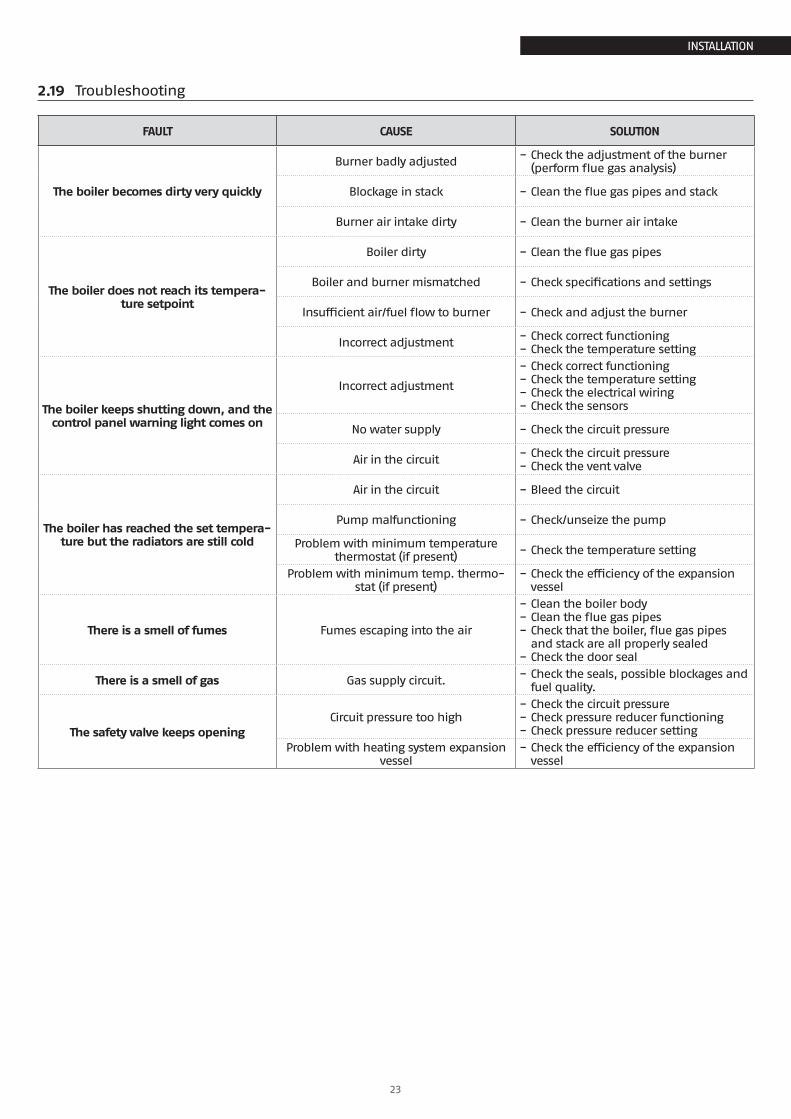
2.19 Troubleshooting
FAULT CAUSE SOLUTION
The boiler becomes dirty very quickly
Burner badly adjusted − Check the adjustment of the burner (perform flue gas analysis)
Blockage in stack − Clean the flue gas pipes and stack
Burner air intake dirty − Clean the burner air intake
The boiler does not reach its tempera-ture setpoint
Boiler dirty − Clean the flue gas pipes
Boiler and burner mismatched − Check specifications and settings
Insufficient air/fuel flow to burner − Check and adjust the burner
Incorrect adjustment − Check correct functioning − Check the temperature setting
The boiler keeps shutting down, and the control panel warning light comes on
Incorrect adjustment
− Check correct functioning − Check the temperature setting − Check the electrical wiring − Check the sensors
No water supply − Check the circuit pressure
Air in the circuit − Check the circuit pressure − Check the vent valve
The boiler has reached the set tempera-ture but the radiators are still cold
Air in the circuit − Bleed the circuit
Pump malfunctioning − Check/unseize the pump
Problem with minimum temperature thermostat (if present) − Check the temperature setting
Problem with minimum temp. thermo-stat (if present)
− Check the efficiency of the expansion vessel
There is a smell of fumes Fumes escaping into the air
− Clean the boiler body − Clean the flue gas pipes − Check that the boiler, flue gas pipes and stack are all properly sealed
− Check the door seal
There is a smell of gas Gas supply circuit. − Check the seals, possible blockages and fuel quality.
The safety valve keeps openingCircuit pressure too high
− Check the circuit pressure − Check pressure reducer functioning − Check pressure reducer setting
Problem with heating system expansion vessel
− Check the efficiency of the expansion vessel
24
USE
USE
3 USE
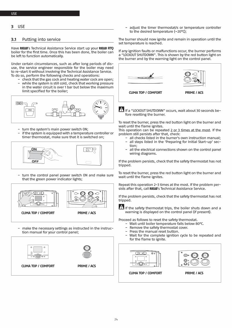
3.1 Putting into service
Have R’s Technical Assistance Service start up your R RTQ boiler for the first time. Once this has been done, the boiler can be left to function automatically.
Under certain circumstances, such as after long periods of dis-use, the service engineer responsible for the boiler may need to re-start it without involving the Technical Assistance Service.To do so, perform the following checks and operations:
− check that the gas cock and heating water cock are open; − while the system is still cold, check that working pressure
in the water circuit is over 1 bar but below the maximum limit specified for the boiler;
− turn the system’s main power switch ON; − if the system is equipped with a temperature controller or
timer thermostat, make sure that it is switched on;
− turn the control panel power switch ON and make sure that the green power indicator lights;
20
4060
80
100
0 120
20
4060
80
100
0 120
CLIMA TOP / COMFORT PRIME / ACS
− make the necessary settings as instructed in the instruc-tion manual for your control panel;
20
4060
80
100
0 120
CLIMA TOP / COMFORT PRIME / ACS
− adjust the timer thermostat/s or temperature controller to the desired temperature (~20°C);
The burner should now ignite and remain in operation until the set temperature is reached.
If any ignition faults or malfunctions occur, the burner performs a “LOCKOUT SHUTDOWN”. This is shown by the red button light on the burner and by the warning light on the control panel.
20
4060
80
100
0 120
CLIMA TOP / COMFORT PRIME / ACS
9 If a “LOCKOUT SHUTDOWN” occurs, wait about 30 seconds be-fore resetting the burner.
To reset the burner, press the red button light on the burner and wait until the flame ignites.This operation can be repeated 2 or 3 times at the most. If the problem still persists after that, check:
− all checks listed in the burner's own instruction manual; − all steps listed in the ‘Preparing for Initial Start-up’ sec-
tion; − all the electrical connections shown on the control panel
wiring diagrams.
If the problem persists, check that the safety thermostat has not tripped.
To reset the burner, press the red button light on the burner and wait until the flame ignites.
Repeat this operation 2-3 times at the most. If the problem per-sists after that, call R’s Technical Assistance Service.
If the problem persists, check that the safety thermostat has not tripped.
9 If the safety thermostat trips, the boiler shuts down and a warning is displayed on the control panel (if present).
Proceed as follows to reset the safety thermostat. − Wait until boiler temperature falls below 80°C. − Remove the safety thermostat cover. − Press the manual reset button. − Wait for the complete ignition cycle to be repeated and
for the flame to ignite.
20
4060
80
100
0 120
20
4060
80
100
0 120
CLIMA TOP / COMFORT PRIME / ACS
Use
25
USE
USE
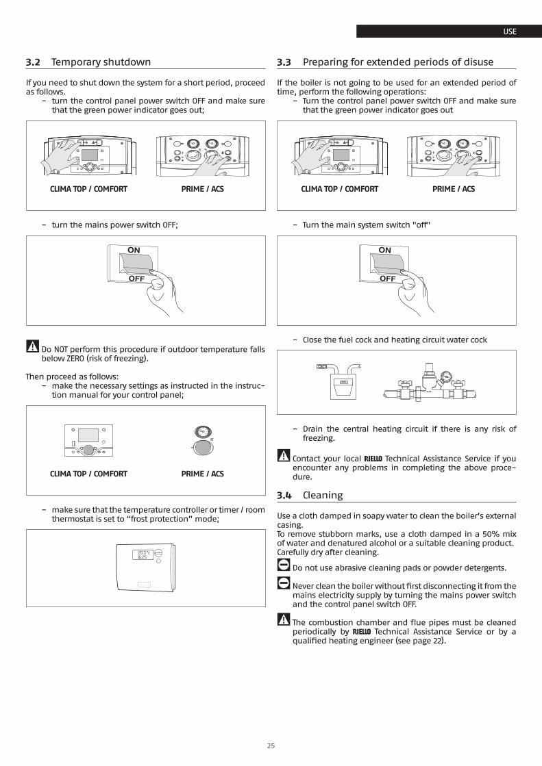
3.2 Temporary shutdown
If you need to shut down the system for a short period, proceed as follows.
− turn the control panel power switch OFF and make sure that the green power indicator goes out;
20
4060
80
100
0 120
20
4060
80
100
0 120
CLIMA TOP / COMFORT PRIME / ACS
− turn the mains power switch OFF;
9 Do NOT perform this procedure if outdoor temperature falls below ZERO (risk of freezing).
Then proceed as follows: − make the necessary settings as instructed in the instruc-
tion manual for your control panel;
20
4060
80
100
0 120
CLIMA TOP / COMFORT PRIME / ACS
− make sure that the temperature controller or timer / room thermostat is set to “frost protection” mode;
3.3 Preparing for extended periods of disuse
If the boiler is not going to be used for an extended period of time, perform the following operations:
− Turn the control panel power switch OFF and make sure that the green power indicator goes out
20
4060
80
100
0 120
20
4060
80
100
0 120
CLIMA TOP / COMFORT PRIME / ACS
− Turn the main system switch "off"
− Close the fuel cock and heating circuit water cock
− Drain the central heating circuit if there is any risk of freezing.
9 Contact your local R Technical Assistance Service if you encounter any problems in completing the above proce-dure.
3.4 Cleaning
Use a cloth damped in soapy water to clean the boiler’s external casing.To remove stubborn marks, use a cloth damped in a 50% mix of water and denatured alcohol or a suitable cleaning product.Carefully dry after cleaning.
0 Do not use abrasive cleaning pads or powder detergents.
0 Never clean the boiler without first disconnecting it from the mains electricity supply by turning the mains power switch and the control panel switch OFF.
9 The combustion chamber and flue pipes must be cleaned periodically by R Technical Assistance Service or by a qualified heating engineer (see page 22).

26
USE
USE
3.5 Maintenance
Please remember that THE PERSON RESPONSIBLE FOR SYSTEM MAN-AGEMENT MUST ENSURE THAT PROFESSIONALLY QUALIFIED HEATING ENGINEERS UNDERTAKE PERIODIC MAINTENANCE AND COMBUSTION EFFICIENCY MEASUREMENTS.
R’s Technical Assistance Service is qualified to satisfy these legal requirements and can also provide useful information on MAINTENANCE PROGRAMMES designed to guarantee:
− Greater safety − Compliance with applicable legislation − Freedom from the risk of fines in the event of spot checks.
Regular maintenance is essential for the safety, efficiency and durability of the boiler.Servicing is a legal requirement and must be performed at least once a year by a professionally qualified heating engineer.
27
USE
USE
3.6 Useful information
Seller: ...............................................................................
Mr.: ..................................................................................
Address: ...........................................................................
Tel.: ..................................................................................
Technical Assistance Service: ..............................................
Mr.: ..................................................................................
Address: ...........................................................................
Tel.: ..................................................................................
Installer: ...........................................................................
Mr.: ..................................................................................
Address: ...........................................................................
Tel.: ..................................................................................
Date Work done
Fuel oil supplier: ...............................................................
Mr.: ..................................................................................
Address: ...........................................................................
Tel.: ..................................................................................
Date Quantity sup-plied Date Quantity sup-
plied Date Quantity sup-plied Date Quantity sup-
plied

RIELLO S.p.A.37045 Legnago (VR) - ItalyTel. 0442630111 - Fax 044222378 - www.riello.it
The manufacturer strives to continuously improve all products. Appearance, dimensions, technical specifications, standard equipment and accessories are therefore liable to modification without notice.


![Bordetella Pertussis virulence factors in the continuing ... · Bordetella polysaccharides (Bps), and their significance in biofilm formation in vitro and in mice [26]. By func-tioning](https://img.pdfslide.us/doc/110x75/5ffe9ca82b08704ea77e4974/bordetella-pertussis-virulence-factors-in-the-continuing-bordetella-polysaccharides.jpg)