Embed Size (px)
Citation preview
TECHNICAL SPECIFICATIONS
Revision 0
March 21, 2018
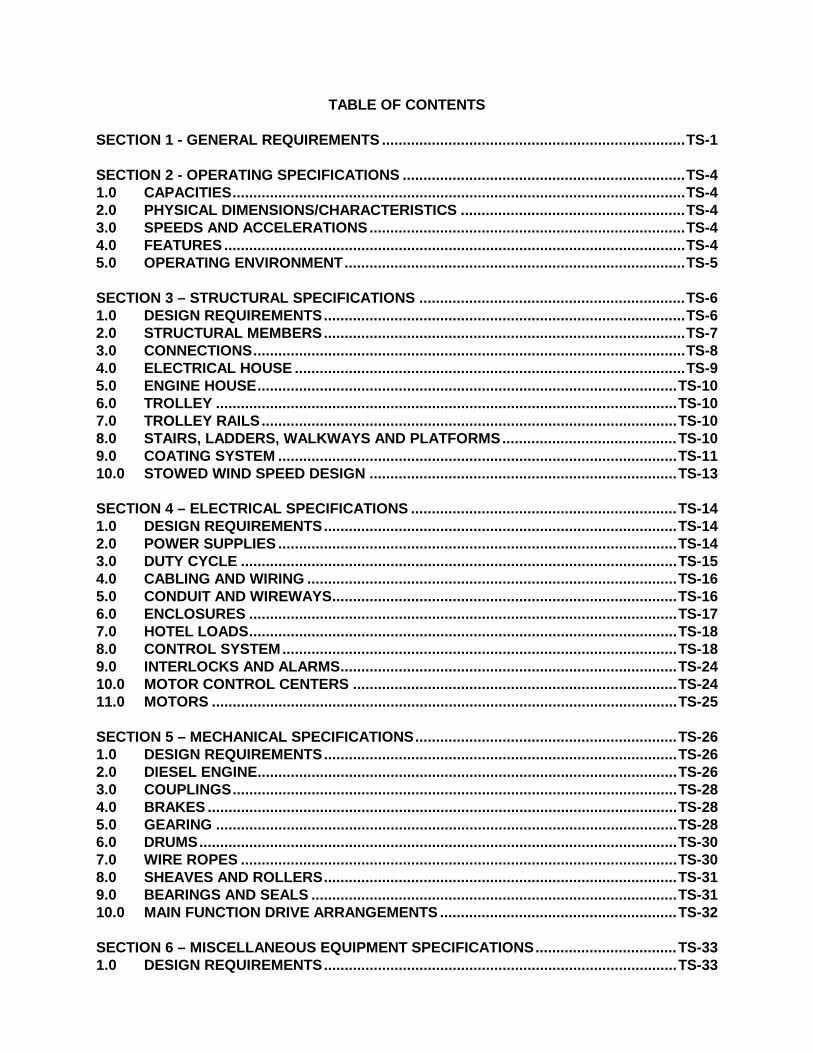
TABLE OF CONTENTS SECTION 1 - GENERAL REQUIREMENTS ......................................................................... TS-1
SECTION 2 - OPERATING SPECIFICATIONS .................................................................... TS-4 1.0 CAPACITIES ............................................................................................................. TS-4 2.0 PHYSICAL DIMENSIONS/CHARACTERISTICS ...................................................... TS-4 3.0 SPEEDS AND ACCELERATIONS ............................................................................ TS-4 4.0 FEATURES ............................................................................................................... TS-4 5.0 OPERATING ENVIRONMENT .................................................................................. TS-5
SECTION 3 – STRUCTURAL SPECIFICATIONS ................................................................ TS-6 1.0 DESIGN REQUIREMENTS ....................................................................................... TS-6 2.0 STRUCTURAL MEMBERS ....................................................................................... TS-7 3.0 CONNECTIONS ........................................................................................................ TS-8 4.0 ELECTRICAL HOUSE .............................................................................................. TS-9 5.0 ENGINE HOUSE ..................................................................................................... TS-10 6.0 TROLLEY ............................................................................................................... TS-10 7.0 TROLLEY RAILS .................................................................................................... TS-10 8.0 STAIRS, LADDERS, WALKWAYS AND PLATFORMS .......................................... TS-10 9.0 COATING SYSTEM ................................................................................................ TS-11 10.0 STOWED WIND SPEED DESIGN .......................................................................... TS-13
SECTION 4 – ELECTRICAL SPECIFICATIONS ................................................................ TS-14 1.0 DESIGN REQUIREMENTS ..................................................................................... TS-14 2.0 POWER SUPPLIES ................................................................................................ TS-14 3.0 DUTY CYCLE ......................................................................................................... TS-15 4.0 CABLING AND WIRING ......................................................................................... TS-16 5.0 CONDUIT AND WIREWAYS ................................................................................... TS-16 6.0 ENCLOSURES ....................................................................................................... TS-17 7.0 HOTEL LOADS ....................................................................................................... TS-18 8.0 CONTROL SYSTEM ............................................................................................... TS-18 9.0 INTERLOCKS AND ALARMS ................................................................................. TS-24 10.0 MOTOR CONTROL CENTERS .............................................................................. TS-24 11.0 MOTORS ................................................................................................................ TS-25
SECTION 5 – MECHANICAL SPECIFICATIONS ............................................................... TS-26 1.0 DESIGN REQUIREMENTS ..................................................................................... TS-26 2.0 DIESEL ENGINE ..................................................................................................... TS-26 3.0 COUPLINGS ........................................................................................................... TS-28 4.0 BRAKES ................................................................................................................. TS-28 5.0 GEARING ............................................................................................................... TS-28 6.0 DRUMS ................................................................................................................... TS-30 7.0 WIRE ROPES ......................................................................................................... TS-30 8.0 SHEAVES AND ROLLERS ..................................................................................... TS-31 9.0 BEARINGS AND SEALS ........................................................................................ TS-31 10.0 MAIN FUNCTION DRIVE ARRANGEMENTS ......................................................... TS-32
SECTION 6 – MISCELLANEOUS EQUIPMENT SPECIFICATIONS .................................. TS-33 1.0 DESIGN REQUIREMENTS ..................................................................................... TS-33
Rev 0 - March 21, 2018
2.0 OPERATOR’S CABIN ............................................................................................. TS-33 3.0 HEADFRAME .......................................................................................................... TS-34 4.0 SPREADER BAR .................................................................................................... TS-35 5.0 ANTISWAY SYSTEM .............................................................................................. TS-37 6.0 DAVIT ..................................................................................................................... TS-37 7.0 HYDRAULIC SYSTEMS ......................................................................................... TS-38 8.0 LUBRICATION SYSTEMS ...................................................................................... TS-39 9.0 COMMUNICATION SYSTEM .................................................................................. TS-40 10.0 EQUIPMENT ENCLOSURES ................................................................................. TS-40 11.0 SPREADER BAR POSITION CONTROL ................................................................ TS-40 12.0 ENERGY CHAIN SYSTEM ..................................................................................... TS-41 13.0 CCTV SYSTEM ....................................................................................................... TS-42 14.0 TRUCK PROTECTION SYSTEM ............................................................................ TS-42 15.0 AUTO STEERING ................................................................................................... TS-42 16.0 GANTRY ANTI COLLISION SYSTEM .................................................................... TS-43
SECTION 7 – PURCHASED COMPONENTS .................................................................... TS-44
SECTION 8 – QUALITY CONTROL, TESTING AND ACCEPTANCE ................................ TS-46 1.0 SCOPE ................................................................................................................... TS-46 2.0 GENERAL ............................................................................................................... TS-46 3.0 RECORD KEEPING ................................................................................................ TS-47 4.0 INSPECTION METHODS ........................................................................................ TS-48 5.0 FABRICATION INSPECTIONS AND TESTS .......................................................... TS-51 6.0 SHOP ERECTION INSPECTION AND SHOP TESTS ............................................ TS-54 7.0 DELIVERY INSPECTIONS ..................................................................................... TS-55 8.0 ACCEPTANCE/PERFORMANCE TESTS ............................................................... TS-55 9.0 CERTIFICATION ..................................................................................................... TS-61 10.0 FINAL INSPECTION AND PUNCH LIST ................................................................ TS-61
SECTION 9 – REQUIRED SUBMITTALS ........................................................................... TS-62 1.0 WITH PROPOSALS ................................................................................................ TS-62 2.0 AFTER AWARD ...................................................................................................... TS-63 3.0 DRAWING AND TECHNICAL DATA, SUBMITTAL LIST,
MINIMUM REQUIREMENTS .......................................................................................... TS-63
TS-1 Rev 0 - March 21, 2018
SECTION 1 – GENERAL REQUIREMENTS CAPACITY (Rated Load): 50 Long Tons under spreader bar with the
capability of handling eccentric loads.
LIFT HEIGHT: 1 over 5 (9.5-foot containers)
GAUGE: 75 feet
OVER-ALL LENGTH: 40 feet maximum
OVER-ALL SPAN: 80 feet maximum
CLEARANCE INSIDE SPAN: 70 feet minimum
HOIST SPEED (at rated load): 100 feet/min. minimum, Accel 1.5 sec., Decel 1.0 sec.
HOIST SPEED (spreader only): 200 feet/min. minimum, Accel 3.5 sec., Decel 2.5 sec.
TROLLEY SPEED (at rated load): 250 feet/min. minimum, Accel/Decel 2.5 sec.
GANTRY SPEED: 450 feet/min. minimum, Accel/Decel 5 sec.
GANTRY/TROLLEY GRADE REQUIREMENTS: 2% maximum grade at full load
NUMBER OF WHEELS: Four (4) wheels per corner (minimum 2 wheel per corner driven)
STEERING: Full steering in cross travel. Rotation about center axis (17 degrees steering).
ELECTRONIC DRIVE: Electronic drive shall be AC. All drive components shall be located in one enclosure above sill beam protected from truck traffic.
CONTROLS: Provide anti-sway equipment for both trolley and gantry directions. Hydraulic systems are not acceptable.
SPREADER AND HEAD-FRAME ASSEMBLY: Furnish one (1) assembly per crane. 20/40/45 all-
electric spreader interchangeable with existing SCPA cranes at the Wando Welch Terminal and Inland Port Greer shall be in the base proposal. Provide side shift, trim, and skew capability.
POWER SOURCE: Modular-frame genset. Alternator shall be machined to bolt directly to engine with self-alignment. Elevated air induction point to reduce dirt ingestion and eliminate water intake.
GROUND CLEARANCE: One foot minimum.
TS-2 Rev 0 - March 21, 2018
SERVICE RECEPTACLES: Provide service outlets (20 amp 110 VAC) on each side at ground level, on trolley deck, three in the Electrical House, and 6 duplex in cab (at least one on a separate 20 amp circuit and one switched).
EMERGENCY STOPS: Provide one at each of the following locations: each gantry leg facing out, truck lane gantry leg facing in, on trolley deck, in the Electrical House, on the local diesel engine control panel, and on the chair console in the operator’s cabin.
STAND-BY POWER: Provide circuitry and connections for auxiliary power (480VAC, 30 amp, 3-phase)
LIGHTING: 300 Lux at ground level within the Working Area
OPERATOR'S CABIN: Climate controlled, ergonomic, no visual obstructions
PAINT SYSTEM: Primer - Suitable Organic Zinc Rich Primer;
Second Coat - Suitable High-Build Epoxy; Third Coat – Suitable Aliphatic Polyurethane
SERVICE CRANE: Electric rope hoist davit crane of appropriate capacity (1 ton minimum) and location to handle removal of equipment located on or above the trolley.
ACCESS: All stairways, ladders, platforms, and walkways shall be OSHA-compliant.
STOWED WIND: The maximum out of service wind speed shall be submitted by the manufacturer based on stowed configuration of the RTG.
TRANSPORTATION METHOD WWT RTGs: The Cranes for Wando Welch Terminal shall be
delivered fully assembled, fully commissioned and pre-tested at the fabrication site before shipment. The proposal shall include a site schedule for offloading thru Substantial Completion of each RTG shipment to WWT and confirm that the working space required at WWT is one and a half times the width of the footprint of the RTGs in the shipment.
TRANSPORTATION METHOD IPG RTGs: The Cranes for IPG Terminal are required to be delivered to IPG by truck and then assembled and commissioned at site. These units shall be structurally pre-assembled at the fabrication site prior to shipment to expedite the on-site assembly at IPG. The proposal shall include a

TS-3 Rev 0 - March 21, 2018
site schedule for assembly and commissioning thru Substantial Completion of each RTG shipment to IPG and include the Work Area required for assembly and commissioning of the Cranes.
TS-4 Rev 0 - March 21, 2018
SECTION 2 – OPERATING SPECIFICATIONS 1.0 CAPACITIES
1.1 A rated load of 50 Long Tons (LT) under the spreader bar. 1.2 Eccentric loads: (RTG is designed for both single and twin twenty operation)
1.2.1 One 32.5 LT 20 ft. Container ± 10% longitudinally and 10 inches transversely with one empty 20 ft. container lifted together, with the maximum 5 ft. separation of the spreader bar.
1.2.2 One 45 ft. container with 50LT load at 55 inches longitudinal eccentricity and 10 in. transverse eccentricity.
2.0 PHYSICAL DIMENSIONS/CHARACTERISTICS 2.1 Lift height 1 over 5 (9.5 ft. containers) 2.2 Gauge 75 ft. 2.3 Overall length 40 ft.(maximum) 2.4 Overall span 80 ft. (maximum) 2.5 Clearance inside span 70 ft. (minimum) 2.6 Wheels per corner 4 (minimum 2 wheels driven)
3.0 SPEEDS AND ACCELERATIONS 3.1 Hoist speed at rated load 100 ft./min. (minimum) 3.2 Hoist acceleration at rated load 1.5 sec. (maximum) 3.3 Hoist deceleration at rated load 1.0 sec. (maximum) 3.4 Hoist speed at no load (spreader only) 200 ft./min. (minimum) 3.5 Hoist acceleration at no load (spreader only) 3.5 sec. (maximum) 3.6 Hoist deceleration at no load (spreader only) 2.5 sec. (maximum) 3.7 Trolley speed at rated load 250 ft./min. (minimum) 3.8 Trolley acceleration/deceleration at rated load 2.5 sec. (maximum) 3.9 Gantry speed 450ft./min. (minimum) 3.10 Gantry acceleration/deceleration 5 sec. (maximum)
4.0 FEATURES 4.1 Capable of traversing a maximum 2% grade at full load and speed. 4.2 Capable of full steering in cross travel. The proposal shall include full operational
description (with arrangement drawings) of the gantry drive, steering and wheel turning system(s).
4.3 Capable of rotating about center axis (17 degree steering). 4.4 Capable of gantrying to a secure location in a 40 mph wind. 4.5 Antisway capability for both trolley and gantry travel directions. Hydraulic antisway
systems are not acceptable. The proposal shall include full operational description (with arrangement drawings).
TS-5 Rev 0 - March 21, 2018
4.6 Capable of handling single 20 ft. or 40 ft. or 45 ft. containers. 4.7 Capable of handling two 20 ft. containers with a separation of up to 5 ft. and a height
difference of at least 6 inches. (RTG is supplied with a single 20/40/45 spreader, but also designed for twin 20 operation.)
4.8 Capable of side shifting, trimming, and skewing the spreader bar.
5.0 OPERATING ENVIRONMENT 5.1 Maximum ambient temperature 105oF 5.2 Minimum ambient temperature -5oF 5.3 Relative humidity 100%
TS-6 Rev 0 - March 21, 2018
SECTION 3 – STRUCTURAL SPECIFICATIONS 1.0 DESIGN REQUIREMENTS
1.1 All structural materials shall conform to ASTM standards for quality, strength, cleanliness, workmanship, and grades.
1.2 The RTG Crane structure: 1.2.1 Shall comply in all respects with the current legislation and relevant
regulation of the F.E.M. 1.001 (Latest Edition) and shall be designed according to the following classifications:
• Class of Utilization: U8
• State of Loading: Q3
• Group: A8 1.2.2 Shall be designed such that allowable stresses for operating conditions,
overload conditions, and fatigue shall be as specified by F.E.M.1.001 (Latest Edition).
1.2.3 Shall be designed to be stable under all conditions specified by F.E.M.1.001 (Latest Edition).
1.2.4 Under dynamic conditions of maximum deceleration, (including both normal E-stop and full regenerative gantry braking in combination with gantry brakes as applicable), with empty spreader at maximum elevation and with Rated Load at maximum elevation, the ratio of stabilizing moments due to all weights of the Crane (DL + TL + LL) to overturning moments due to dynamic inertial effects and simultaneous worst case operating wind shall be no less than 1.4.
1.2.5 The effective fatigue load shall be the load which hangs from the trolley including headblock and spreader, portions of the lifting ropes, sheaves, and the rated load (50LT). For design, the spreader weight shall be no less than 14 ST (28,000lbs)
1.3 Structural connections shall be welded rather than bolted except for erection joints. 1.4 Welded joint design shall conform to applicable provisions of AISC and AWS. 1.5 All bolts ½ inch or less shall be stainless steel. 1.6 All exposed equipment (motors, gearboxes, brakes, conduit, terminal boxes, etc.)
shall be heavily guarded against truck impact. 1.7 All structures shall have a minimum ground clearance of one foot accounting for the
maximum grade. 1.8 The crane shall be capable of traveling over occasional portions of runway
elevations that are 100% in excess of those specified in FEM 1.001 without buckling or yielding of any structural member.
1.9 The design features, all materials used, and the coating system shall be designed for the operating environment. Allowances shall be made for the heating effects of solar radiation.
1.10 The maximum operating wheel loads shall be provided as part of the proposal.
TS-7 Rev 0 - March 21, 2018
2.0 STRUCTURAL MEMBERS 2.1 All welding shall be performed by AWS certified welders, or SCPA approved equal,
certified for the processes and procedures used. 2.2 The Contractor shall maintain material traceability for all structural members and
fasteners from the prime mill source through all manufacturing processes to and including each finished part. Original mill test reports, showing conformance to all specified requirements, shall be furnished for all material. Certification papers shall be required from all sources who determine chemistry, cleanliness, mechanical properties and notch toughness properties. The Contractor shall provide all items in connection with these requirements at no additional cost to the Owner. Where material does not conform to a relevant current Standard Specification, sufficient information shall be provided for the Engineer to identify suitability of the material.
2.3 All major structural sections shall be erected at the fabricator’s facility to insure proper fit. Progress photographs of this procedure shall be submitted and approved prior to shipping.
2.3.1 This requirement also applies to the two (2) RTGs for IPG which will be re-assembled at IPG after transport.
2.4 Major structural members shall be box sections rather than “I-Beam” or compound structures.
2.5 All box members shall be made air tight by seal welding unless: 2.5.1 It is not practical and approved by the Owner or 2.5.2 Access is required for internal inspections.
2.6 Sealed members shall be pressure tested to 1.493 psi, using soap film to demonstrate air tightness.
2.7 Non-sealed members: 2.7.1 Shall be provided with piped drains. The drains shall be at the lowest point to
drain any accumulated moisture or condensation. 2.7.2 Shall include inspection access (manholes). 2.7.3 Shall be sealed adequately by means other than caulking to preclude water
intrusion. 2.8 Manholes shall:
2.8.1 Have edges of openings raised such as would result with doublers. 2.8.2 Have hinged manhole doors which do not collect water, use rubber gaskets,
and are lockable to prevent unauthorized entry. 2.8.3 Be vertically mounted and hinged with handles where possible. 2.8.4 Be outside of or at the end of normal walkways where vertical mounting is
not possible. 2.8.5 Be painted safety yellow if they may be a tripping hazard.
2.9 All structures shall be designed to prevent the retention of water and other debris. 2.10 Any piped drains shall be a minimum of 1.25-inches in diameter. 2.11 Shop and field erection lugs that will not interfere with the operation of the Crane(s)
TS-8 Rev 0 - March 21, 2018
or personnel and in the Engineer’s opinion, are not detrimental to the Crane(s)'s appearance shall be left on the crane for potential hangers of painting scaffolds. The structure shall have sufficient lugs for painting and maintenance purposes. All welding, including that required to install platforms, ladders, electrical wiring, terminal boxes, limit switches, etc. shall be completed prior to painting.
2.12 The design shall carefully consider fatigue and shall provide transition elements (corner gussets, sloped thickness changes, etc.) to minimize effect of stress concentrations.
2.13 The design shall avoid as much as possible welding in areas where high stresses and/or considerable fatigue stresses might occur.
2.14 The design of access platforms shall provide sufficient access for maintenance personnel to service all components, including the removal of the components.
2.15 Steel plate diaphragms shall be provided inside box-type members to back-up all concentrated loads and connections.
2.16 Material used for longitudinal structural stiffeners shall have the same yield stress as the plate to which it is attached.
3.0 CONNECTIONS 3.1 All connections shall be detailed so as to provide for a ductile frame structure
capable of withstanding yielding without brittle failure. The Engineer may require redesign of connections which, in his opinion, cause unnecessarily high stress concentrations and/or restraint.
3.2 Bolted splices of box members shall not be used unless necessary and approved by the Engineer. All splices shall be designed to prohibit entrance of water between plates by means other than caulking. Splice details are subject to review of the Engineer.
3.3 Connections shall be designed for member loads based on the average of the allowable and the calculated stress, but they shall be designed for not less than 75% of the allowable strength of the member. Notice that whenever calculated stresses are less than 0.5 times allowable stress, the 75% requirement applies.
3.4 Stress at weld throats shall be calculated as the vector sum of individual stresses applied to the weld throat. For fatigue design when calculating stress range, the vector difference of the greatest and least vector sum stress may be used instead of the algebraic difference.
3.5 Welded joint design shall conform to applicable provisions of AISC and AWS for dynamically loaded structures.
3.6 Intermittent welding shall not be permitted in areas exposed to the atmosphere, (including interiors of non-airtight structures and interiors of structures such as the Electrical House).
3.7 Bolted joints shall be provided in accordance with ASTM F3125 Standards. 150ksi bolts (also known as A490 bolts and 10.9 GB HS Bolts) may be used with approval of the Owner. The surface of all plates or members intended to be joined together shall be in contact over the whole area, and where stiffeners are necessary, they shall bear tightly both at the top and at the bottom. Prying action and bolt fluctuating stress shall be considered. The faying surfaces of all main structural friction-type bolted connections shall be machined. Bolt heads and nuts shall be marked with a
TS-9 Rev 0 - March 21, 2018
paint marker after final erection for subsequent structural inspections. 3.8 High strength bolts shall not be hot dip galvanized. All bolts shall have a maximum
of two to three threads remaining after tightening. 3.9 If A325 fasteners are used – they shall be hot dipped galvanized. 3.10 Pins shall not be used for connections subject to reversal of loads in the operating
condition. 3.11 Eyebars and pin connected members shall be designed in accordance with AISC
Specification using 0.9 times AISC allowable values, and shall be checked for fatigue using the allowable net section stress range for Class F details. If the net section is governed by fatigue, then all other proportions shall be increased on a basis consistent with the AISC requirements. Complete fabrication drawings for the pins and their bearings shall be included in the Maintenance and Inspection Manuals.
3.12 Longitudinal stiffeners must be welded on both sides. One-sided welding is not permitted unless specifically agreed in writing by the Engineer.
3.13 Fastener assembly bolt torque shall be indicated on the assembly drawings.
4.0 ELECTRICAL HOUSE 4.1 All electronic drive components shall be located in a single enclosure (the Electrical
House), if possible, above the sill beam to protect it from truck traffic. It should be flush with the inside of the gantry leg to reduce exposure to damage from container stacks. This enclosure shall be water tight, aesthetically appealing, and constructed of steel plate and structural shapes.
4.2 The Electrical House shall be accessed from the ground by a retractable ladder. 4.3 The Electrical House shall have an outward opening, waterproof, metal door with a
lock and a safety glass window in the upper panel. It should open away from the access ladder. A steel awning shall be provided over the door. An automatic closer with a latching device capable of withstanding high wind to hold the door open shall also be provided. All door hardware, including the closer, shall be stainless steel and Owner approved.
4.4 A continuous rubber carpet free of all metallic items and a minimum of 1/2 inch thick shall be provided on all floor areas of the Electrical House.
4.5 The Electrical House shall be equipped with a thermostatically controlled heater/air conditioner which will maintain conditions of 65-80oF and less than 50% relative humidity under all operating environment conditions.
4.6 The layout of electrical equipment shall provide adequate space and access to all required equipment.
4.7 If it is not possible to locate all drive components in the Electrical House, all enclosures containing drive components shall meet the above requirements.
4.8 A means of safely removing and replacing equipment in the Electrical House exceeding 50 lbs shall be provided.
TS-10 Rev 0 - March 21, 2018
5.0 ENGINE HOUSE 5.1 The main diesel-generator set shall be located in a single enclosure (the Engine
House) below the sill beam for easy access. It should be flush with the inside of the gantry leg to reduce exposure to damage from container stacks. This enclosure shall be water tight (except for air induction points), aesthetically appealing, and constructed of steel plate and structural shapes.
5.2 The Engine House shall have elevated air induction points to reduce dirt ingestion and eliminate water intake.
5.3 The Engine House shall be sound insulated to sufficiently reduce engine noise levels exterior to the Engine House below noise levels requiring the use of hearing protection.
5.4 The Engine House shall have hinged doors capable of being opened to fully expose and allow removal of equipment mounted inside. Latches shall be provided to secure all doors when opened for servicing; and such latches shall be adequate to secure doors in high winds.
6.0 TROLLEY 6.1 Trolley wheels, side rollers, bearings, axles and rails shall be sized in accordance
with AISE Standard No. 6. Wheels shall be double flanged, rolled steel and rim toughened, to standards of ASTM A504, Class C.
6.2 The trolley shall consist of a structural steel frame supported by at least four double flange wheels.
6.3 Side rollers shall be provided on the inside and outside of the trolley rail (welded bar stock). The basic arrangement of the side rollers shall be submitted with the proposal.
6.4 The trolley and operator’s cabin shall be fully accessible at any point in the trolley's travel and access shall be such that a disabled operator can be removed without special rigging.
6.5 The trolley shall be completely decked with checkered plate or grating and shall be enclosed with a hand railing with kick plates.
6.6 All components on the trolley shall be safely accessible for maintenance and replacement.
6.7 Drop blocks shall be provided to support the trolley if an axle breaks. 6.8 The trolley shall be equipped with at least five devices meeting OSHA requirements
for tying off fall protection equipment: one in each corner and one in the center.
7.0 TROLLEY RAILS 7.1 Bar-stock shall be used for the trolley rail. It shall be continuously welded to the rail
base and its upper surface shall be at least as hard as the trolley wheel surface.
8.0 STAIRS, LADDERS, WALKWAYS, AND PLATFORMS 8.1 All stairs, ladders, walkways, and platforms shall conform to OSHA requirements for
dimensions and loading and shall meet all local codes in all respects. They shall be designed to sustain a distributed load of at least 100 psf and a concentrated load of at least 250 lbs. They shall be constructed of hot-dipped galvanized steel.
8.2 Walkways and platforms shall have a toe plate with a minimum height of 4 in and a
TS-11 Rev 0 - March 21, 2018
minimum thickness of 5mm. 8.3 Stairs, ladders, walkways, and platforms shall be provided to make readily
accessible all parts and areas to which access is required for operation, lubrication, service, maintenance or inspection, including structural inspections for the structural maintenance program and servicing of floodlights.
8.4 Walkways, platforms, and stair treads shall be covered with hot-dipped galvanized steel bar grating. All grating and stair treads shall be connected to the frames by galvanized saddle clips and/or stainless steel bolts.
8.5 Tread noses on stairs shall be of a standard round nose anti-slip type. 8.6 All walkway hardware, for attaching lights, panels, and for gates, etc., shall be
stainless steel. 8.7 Hollow members (pipe or square tube) minimum 4mm wall thickness shall be used
for handrail. They shall be hot dip galvanized inside and out. Holes shall be oriented vertically downward. The height of stair handrail shall be between 35 and 36 in and meet the other requirements of OSHA 1917.12b(4).
8.8 All openings in handrails shall be equipped with hinged gate arranged to close safely by gravity.
8.9 Vertical ladders shall be avoided and used only if approved by the Owner. Ladders shall be double-rung, square-stock, oriented with one corner vertical, and equipped with safety cages as required by the appropriate codes. Platforms shall be furnished to limit the straight vertical run of a ladder to 20 ft. Rungs shall be spaced nominally at 1 ft. with a minimum of 7 in. toe clearance to the nearest obstruction.
8.10 All stair, ladders, walkways, and platforms shall be adequately braced to prevent sway and excessive vibration.
8.11 A service platform shall be provided and sized to permit washing of all operator’s cabin windows.
8.12 All service platforms shall be equipped with at least one device meeting OSHA requirements for tying off fall protection equipment.
8.13 All galvanized components shall be hot-dipped with a minimum coverage of 2-1/2 oz per sq. ft.
9.0 COATING SYSTEM 9.1 Walking surfaces of horizontal girders shall be covered with a paint type nonskid
surface after application of the coating system.
9.2 All coats shall be applied in accordance with the paint manufacturer's recommendations.
9.3 The coating system used shall be provided with a full five (5) year warranty by the Contractor with responsibility as defined below. The coating system shall be generally as follows, but the Contractor shall confirm with the paint supplier that the coating system meets the paint supplier’s requirements to be warranted for the full five years and confirmation shall be submitted to Owner for review.
TS-12 Rev 0 - March 21, 2018
9.4 Prior to the first coat all welds and areas damaged by welding shall be power tool cleaned to SSPC-SP3 or grade ST3 finish and the airtight testing shall be completed. (External surfaces damaged by welding may be primed prior to airtight testing. Weld damaged areas of internal surfaces of sealed sections shall be cleaned and primed prior to airtight testing).
9.5 Interior Sealed (Air-tight) Surfaces
Minimum Dry Film Type Coating Thickness (Microns)
Shop Primer Pre-Construction Primer 25
9.6 Interior Non-sealed Surfaces
Minimum Dry Film Type Coating Thickness (Microns)
Shop Primer Pre-Construction Primer 25
Prior to the first coat all welds and areas damaged by welding shall be power tool cleaned to SSPC-SP3 or grade ST3 finish.
First Coat Suitable Organic Zinc Rich Primer 80
Second Coat Suitable High-Build Epoxy 125
9.7 Exterior Surfaces
Minimum Dry Film Type Coating Thickness (Microns)
Shop Primer Pre-Construction Primer 25
Prior to painting, the surfaces shall be blasted to SSPC-SP10 finish.
First Coat Suitable Organic Zinc Rich Primer 80
Second Coat Suitable High-Build Epoxy 100
Third Coat Suitable Aliphatic Polyurethane 80
9.8 Each coat shall be of a contrasting color. Finish coat colors shall be as specified
by Owner and in compliance with applicable codes and regulations at the erection site.
9.9 The second and third coats shall be applied after all shop welding has been completed.
9.10 Not more than seventy-two (72) hours prior to the application of the second and

TS-13 Rev 0 - March 21, 2018
third coats, all surfaces shall be cleaned to remove all the surface contaminants. Coating abrasion from construction and welding shall be repaired as per original coating specifications before the second coat is applied.
9.11 Galvanized parts shall not be painted. 9.12 Exposed, purchased components (motors, gearboxes, cabins, houses, enclosures,
etc.) shall be top coated with the exterior coating system. 9.13 The Contractor shall paint the Owner’s logos at locations as directed by the Owner. 9.14 After final construction, shipping transportation and erection damaged areas shall be
repaired in accordance with the coating system manufacturer’s recommendations.
10.0 STOWED WIND SPEED DESIGN 10.1 The proposal shall include the maximum wind speed that the RTG is stable in the
stowed arrangement (alternate wheels turned) with the spreader secured to a 30LT container within the container stack.
TS-14 Rev 0 - March 21, 2018
SECTION 4 – ELECTRICAL SPECIFICATIONS 1.0 DESIGN REQUIREMENTS
1.1 Electrical work and equipment shall conform to the latest editions of NEMA, IEEE, NEC, UL, IEC, ANSI, and other applicable local codes, agencies or bodies having jurisdiction at the Installation Site.
1.2 All electrical equipment shall meet OSHA requirements for locking and tagging procedures to disable it for servicing.
1.3 All electrical equipment shall conform to guarding and servicing requirements of OSHA and NEC.
1.4 All electrical equipment and systems shall be adequately protected against radio frequency interference.
1.5 All major electrical equipment shall be furnished with lifting lugs for ease of attaching hoist gear.
1.6 All materials or combination of materials shall be selected for maximum corrosion resistance.
1.7 Aluminum or aluminum alloys shall not be used for housings, fans, blowers, motors, motor brakes, energy chain parts or other weather exposed parts or components unless otherwise indicated in these specifications.
1.8 Ferrous components not contained in weatherproof enclosures shall be galvanized after fabrication and before painting. Cadmium plating is not acceptable.
1.9 All screws, bolts, nuts, washers, pins, studs, springs, and other miscellaneous fastenings and fittings shall be of corrosion resistant materials such as monel or stainless steel.
1.10 The design features and all equipment and materials used shall be designed for the operating environment. Allowances shall be made for the heating effects of solar radiation. Space heaters shall be used and sized to protect de-energized equipment. Adequate consideration shall be given to temperatures within enclosures and to ventilation during operation.
1.11 To ensure proper set up and adjustment of the control system, which is essential to the achievement of full crane performance and efficiency, the Contractor shall furnish, at no additional cost to the Owner, a Control System Supplier field service representative to assist in the drive set-up and commissioning at the fabrication site, and at the erection site, and for thirty days after Substantial Completion of each RTG Crane. The representative must have full knowledge and experience with the drive system, a good command of the English language, and be Owner-approved.
1.12 Circuit breakers shall be used on any circuit when CBs can provide adequate protection for the circuit. Where fuses are required, they shall be of the fault indicating type if available.
2.0 POWER SUPPLIES 2.1 Normal power for all electrical loads shall be 480VAC, 3-phase, 60 Hz electrical
power. It shall be provided by a modular-frame diesel-generator set. The alternator shall be machined to bolt directly to the diesel engine with self-alignment.
2.2 The normal power supply circuit shall be monitored for under voltage, over voltage,

TS-15 Rev 0 - March 21, 2018
phase loss, phase sequence, and phase imbalance. 2.3 Circuitry and connections to the Owner’s auxiliary power supply (480VAC, 3-phase,
60 Hz, 30 amp) shall be provided for the following loads: 2.3.1 Equipment heaters. 2.3.2 Panel space heaters and lighting. 2.3.3 Davit hoist(s). 2.3.4 Electrical House lighting and climate control system. 2.3.5 Engine House lighting. 2.3.6 Operator’s cabin lighting. 2.3.7 All 120VAC service receptacles. 2.3.8 Stair, ladder, walkway, and platform lighting. 2.3.9 Floodlights. 2.3.10 Battery operated emergency lighting.
2.4 Provide an automatic transfer system (ATS) which seeks the normal power supply. The ATS shall automatically transfer power to the auxiliary power supply when the normal power supply fails. Upon restoration of the normal power supply, the ATS circuit shall transfer power to the normal power supply. The ATS shall have mechanical and electrical interlocks, and no key-switch interlocks.
3.0 DUTY CYCLE 3.1 The Crane(s) shall be capable of continuous and simultaneous hoisting and trolley
traveling or gantrying and trolley traveling with loaded containers in repetitive cycles in accordance with the aforementioned speed requirements. Mechanical and electrical equipment shall be selected for the critical cycle involved, plus torque ratings and thermal heating capacity. All motor specifications requirements for acceleration/deceleration rates apply with 50% operating wind from the worst-case direction.
3.2 The Contractor shall submit a theoretical duty cycle analysis for each drive prepared by the electrical control system supplier, which verifies the adequacy of the selected equipment and diesel generator for the specified cycle.
3.3 The theoretical duty cycle for use in calculating times and equipment ratings of the hoist and trolley drive systems shall be SCPA approved and consist of removing and replacing containers from chassis and from grounded stacks. The duty cycle shall be calculated based on removing and replacing the stacked containers (5 high x 6 wide) from the stacks and loading (and off-loading) onto chassis. For the purpose of this calculation, the truck lane will be adjacent to the sill beam without the diesel and the spacing between container stacks is 300mm. The equipment ratings shall also consider the various worst case container handling cycle paths encountered in container handling operations.
3.4 The Contractor shall submit for review, the theoretical duty cycle block diagram for the main hoist and trolley drive
3.5 The theoretical duty cycle for the sideshift/trim/skew system components shall consider the above main hoist and trolley duty cycle with the systems completing two operations per container cycle.

TS-16 Rev 0 - March 21, 2018
4.0 CABLING AND WIRING 4.1 All electrical cabling and wiring shall be:
4.1.1 Stranded copper with flame retardant, heat resistant, oil and moisture resistant, thermoplastic insulation with a nylon jacket
4.1.2 Sized in accordance with applicable Regulations and Codes of Practice, National Electric Code.
4.1.3 Suitably derated to suit ambient temperatures.
4.2 Minimum conduit wire size shall be 12 AWG. Minimum wire size in cable trays and cable ladders shall be 14 AWG
4.3 All cabling shall be protected from direct sunlight and be exterior rated tray cable with sunlight resistant insulation. SO chord is not acceptable.
4.4 All electrical cabling and wiring shall be labeled with heat shrink labels with stamped text at all terminations and identified on the schematics, including cable numbers and their individual wire numbers.
4.5 Heat shrink lugs shall be used on all terminations. Pin lugs shall be used in control wiring terminations. The heat shrink sleeve shall be continuous from the lug sleeve and overlap the wire insulation by at least one quarter (1/4) inch.
4.6 All spare wires shall be labeled, lugged, and terminated. 4.7 Wiring internal to junction boxes shall be MTW wire. 4.8 Wire bundles in junction boxes shall be bundled using wire ties that are UV rated
and utilize a metal tooth. These wire bundles shall be anchored to junction box terminal plates with straps and screws. Screw holes shall be tapped.
4.9 14 awg wire shall be 30 strand and 12 awg wire shall be 41 strand. 4.10 Fiber optic cable shall be used for all control system communications except for runs
within the same panel or within the Electrical House.
5.0 CONDUIT AND WIREWAYS 5.1 All conduit and wireways shall be:
5.1.1 Neatly arranged on the exterior of the structure and located so as to prevent any possible damage due to swinging loads or truck traffic.
5.1.2 Installed in accordance with the applicable Regulations and Codes of Practice, NEC.
5.2 All cabling and wiring shall run in cable tray type wireways whenever possible. 5.3 The electrical connection to the trolley shall be through an Owner approved energy
chain system. The proposed energy chain system type shall be identified in the proposal.
5.4 Cable tray shall be covered and constructed of 304 stainless steel. The covers shall not be installed until after erection or they shall be removed during erection and reinstalled after erection.
5.5 All cabling and wiring run in cable tray shall be secured with only plastic-coated stainless steel cable ties.
5.6 Conduit, where Owner approved shall be galvanized, seamless and all cut threads
TS-17 Rev 0 - March 21, 2018
will be cold galvanized. 5.7 Flexible conduit shall be:
5.7.1 Used only where required to accommodate relative motion and Owner approved.
5.7.2 UL approved. 5.7.3 Liquid tight flexible nonmetallic conduit. 5.7.4 Terminated in approved end fitting from the same manufacturer.
5.8 All AC power and control, DC power and Low Level digital and analog communication circuits shall be segregated to avoid inducement of noise. The Contractor shall strictly adhere to the installation guidelines, requirements and recommendations of the Control System manufacturer. The following guidelines shall apply as a minimum: 5.8.1 Cabling and/or wiring of different voltage levels shall be segregated in cable
tray with a minimum separation of six (6) inches and a metal barrier or in separate conduits.
5.8.2 Where low voltage/communication wiring must cross power wiring, it shall be at a right angle.
5.9 To provide optimum personnel safety, cabling and wiring for AC and DC power shall be run in segregated cable tray with a metal barrier or separate conduits.
5.10 All cable runs shall have 10% spares (minimum of two) for each type of cable in the run. The energy chain cables shall contain at least 15% spares.
6.0 ENCLOSURES 6.1 All enclosures (junction boxes, terminal boxes, pull boxes, outlet boxes, panels, etc.)
in locations exposed to the weather shall be of the hood latch type and comply with NEMA 4x (316 stainless steel) at a minimum. Cover screws shall not extend into any watertight enclosure.
6.2 Enclosures (junction boxes, terminal boxes, pull boxes, outlet boxes, etc.) in locations not exposed to the weather shall comply with NEMA 12 at a minimum.
6.3 Panels shall be accessible and removable from the front. Adequate access for service and maintenance shall be provided in front of all panels.
6.4 All enclosure covers shall be hinged and shall be capable of being opened to fully expose and allow removal of equipment mounted inside. Latches shall be provided to secure all covers when opened for servicing.
6.5 All enclosure penetrations shall use weather-proof bushings. All penetrations to enclosures exposed to the weather shall be from below.
6.6 All AC power and control, DC power and Low Level digital and analog communication circuits shall be segregated to avoid inducement of noise. The Contractor shall strictly adhere to the installation guidelines, requirements and recommendations of the Control System manufacturer. As a minimum, cabling and/or wiring of different voltage levels shall be in separate enclosures if possible.
6.7 To provide optimum personnel safety, cabling and wiring for AC and DC power shall be run in separate enclosures. Enclosures that must contain both AC and DC power supplies shall be appropriately labeled.
TS-18 Rev 0 - March 21, 2018
6.8 Terminal blocks shall be modular.
7.0 HOTEL LOADS 7.1 Duplex service outlets (120 VAC, 1 phase, 60 Hz, 20 amp, ground-fault type) shall
be provided at the following locations: 7.1.1 One on each gantry leg at ground level. 7.1.2 One on the trolley deck. 7.1.3 Three in the Electrical House. 7.1.4 Six in the operator’s cabin, with a minimum of one being on its own 20 amp
circuit and one being switched (for YMS). 7.2 Watertight LED floodlights (480 VAC, 3 phase, 60 Hz) shall provide 300 Lux at
ground level. The working area shall be 45ft wide the entire length from the outside of one sill beam to outside of the other at ground level. All floodlights shall be provided with external safety chains that connect the lamp fixture to the foundation.
7.3 Stair, ladder, walkway, and platform lighting shall provide a minimum illumination of 50 Lux. LED lights shall be used for this lighting.
7.4 Electrical House and Engine House lighting shall provide a minimum illumination of 300 Lux.
7.5 Operator’s cabin lighting shall be LED lighting, provide a minimum illumination of 100 Lux and shall be dimmable.
7.6 Electrical panel lighting shall provide a minimum illumination of 100 Lux inside the panel. This lighting shall be switched such that it is on when the panel door is open and off when the panel door is closed.
7.7 All interior lighting shall be 120 VAC wet and damp location LED fixtures wherever possible.
7.8 Battery powered emergency lighting with a minimum 3 hour duration shall be provided in the Electrical House and the operator’s cabin.
8.0 CONTROL SYSTEM 8.1 The control system shall include the following equipment:
8.1.1 AC digital electronic drive(s) for AC variable speed control for all RTG Crane functions.
8.1.2 Programmable logic controller(s) for electronic drive coordination and sequencing.
8.1.3 Operator chair consoles and operator interface panels for controlling or monitoring RTG Crane functions.
8.1.4 Control and feedback devices. 8.1.5 An integral Crane Monitoring and Diagnostic system (CMS). 8.1.6 All instruments, test devices, monitors, computers, software (with applicable
software licenses), and other devices required for control system diagnostics, troubleshooting, or maintenance including all devices necessary to upload, download, or change software or to configure or test I/O blocks. If the item is required for troubleshooting or diagnostics, one shall be provided for each
TS-19 Rev 0 - March 21, 2018
RTG Crane. Otherwise one item shall be provided for each terminal receiving RTG Cranes. If laptop computers are used solely for uploading, downloading, or changing software, then one laptop shall be provided for each terminal receiving RTG Cranes. Regardless of the number of laptop computers provided, an additional laptop computer shall be provided for the Owner’s Electrical Technical Specialist. In addition to the below requirements, this laptop shall have all operator interface/HMI programming software installed. Each laptop shall be provided with the following as a minimum:
• Intel i7 or better processor.
• 8GB RAM.
• CDRW drive.
• Windows 7 pro (certified) 64 bit operating system.
• PLC programming software installed.
• PLC network card and cable.
• All applicable software licenses. 8.1.7 Any other devices required to meet the intent of these specifications for the
safe, reliable, and efficient control of the RTG Cranes. 8.2 The control system shall provide reliable power for rapid, smooth, and precise
handling of containers. It shall be designed for maximum simplicity and maintainability and failsafe operation in the case of any one failure. It shall provide faster hoisting and lowering speeds for loads less than rated by maintaining constant horsepower and it shall safely regulate zero speed. The primary method of determining speed versus load characteristics shall be calculated by the drive using motor current feedback, not by using load cells.
8.3 The control system shall provide torque-proving circuits to prevent release of the motor brake(s) unless the motor develops adequate torque to control the load.
8.4 The control system shall be designed to use dynamic regenerative braking through the motor and electronic drive, dissipating the energy into a resistor load bank. Mechanical brakes shall not be used to slow normal operating functions.
8.5 All master switch controlled motions shall have a circuit which compares the motion drive reference to the motion feedback (tach or voltage feedback) - sometimes referred to as a "tach loss" circuit. If a preset error difference is exceeded, a fault shall occur and the motion stops.
8.6 Control of main hoist, trolley, and gantry motors shall be stepless, digitally regulated, and regenerative over the entire range of the equipment. The operator shall be able to increase or decrease the speed of the motors and alter their direction by moving a master switch in the appropriate manner. The acceleration and deceleration of the motors shall be under the control of the operator, except that if the operator moves the master switches rapidly, acceleration and deceleration shall be limited, automatically, to predetermined adjustable values. The linear time ramps for the trolley and gantry motions shall be symmetrical with equal acceleration and deceleration times in either direction. The linear time ramps for the main hoist may be asymmetrical. All ramps shall have the capabilities for adjustable rate of change of both acceleration and deceleration. When the operator moves the master switch
TS-20 Rev 0 - March 21, 2018
toward the "off" position, the load shall be slowed electrically. The speed of all motions shall be infinitely variable from full speed through zero to full speed in the opposite direction with no dead band.
8.7 Brakes for the main hoist, trolley, and gantry shall set and the loop contactors open after independently adjustable (adjustable in the PLC) time delays (0-30 seconds) when the master switches are returned to the off position. The control circuits shall be so designed that all brakes are delayed in setting during normal operation until the associated motor has been slowed to approximately 5% or less of rated speed, at which time the adjustable delay shall begin. The motor torque shall be maintained until the brakes have set. If control power has been removed for any reason, all brakes shall set immediately.
8.8 The time between the initial movement of the master switch and the start of rotation of the corresponding machinery for the main hoist shall not exceed seven tenths of a second. The time between the initial movement of the master switch and the start of rotation of the corresponding machinery for the trolley and gantry shall not exceed four tenths of a second.
8.9 The control system supplier shall have responsibility to review the design and installation of the entire electrical system, including the diesel-generator set, and certify to the Owner that the design and installation are in conformance to the control system requirements.
8.10 The control system supplier shall be required to attend at least the first two (2) design review meetings to facilitate communication and coordination.
8.11 Adequate protection against interfering radio frequency shall be provided throughout the control system.
8.12 All control system electric or electronic components shall be protected from electrical surges and transients and from lightning. The minimum requirements are as follows: 8.12.1 All power semi-conductors and electronic equipment must be equipped with
voltage surge protective devices. All power semi-conductors must also be protected from lightning induced transients on the output wiring connecting the variable speed drives to the motors.
8.12.2 All transient and surge protective devices (voltage clamping devices and resistive-capacitive snubbers) must be capable of continuous operation at +20% of rated supply voltage.
8.12.3 All power semi-conductors must have a minimum voltage rating of 1600 volts.
8.12.4 All control and communication inputs, outputs, and data ports must be equipped with adequate protective devices for protection against voltage transients entering the system via interface and remote wiring. Communication and data ports must be designed to comply with IEC 1000-4-5, Level 3, surge test. Control inputs and outputs must be designed to comply with IEC-4-5, Level 4, surge test. Communication and data ports must also be equipped with galvanic isolating devices (optical, etc.) capable of operating with ground potential differences of 500 volts rms.
8.12.5 Surge protection shall be provided across all relays and contactors. 8.13 The AC electronic drive(s) shall:
TS-21 Rev 0 - March 21, 2018
8.13.1 Have linear control from the master switches. This is defined as a proportional speed change from master switch to motor speed, independent of the load.
8.13.2 Use IGBT power devices. Bi-polar transistor-based drives are not acceptable.
8.13.3 Be equipped with AC input reactors or DC link reactors to improve harmonic input profile of drive input current.
8.14 The AC electronic drive cabinets shall: 8.14.1 Have master circuit breakers or isolation switches that will de-energize all
electrical components in the cabinet. 8.14.2 Be arranged to provide access to the IGBT assemblies without moving or
removing other components. 8.14.3 Have all power wiring termination brought to terminal studs mounted at the
bottom of the control panel. Control wiring terminations shall be mounted such that they are easily accessible and at a comfortable working height. In no case shall external power or control connections be made directly to drive control units.
8.14.4 Have at least fifteen percent (15%) spare terminal blocks. 8.14.5 Be equipped with panel heaters to prevent condensation when de-energized.
8.15 The PLC shall: 8.15.1 Control all electronic drive functions, interlocking, and sequencing except for
emergency stops and end of travel circuits. Emergency stop and end of travel circuits shall be hardwired to the electronic drive unless a safety PLC is used.
8.15.2 Have operating voltages not to exceed 50 volts except for the 120 VAC supply to the Regulated Power Supply that powers the PLC.
8.15.3 Have control wiring rated for 600 volts. 8.15.4 Have I/O rated for 24 VDC. 8.15.5 Have all control inputs wired to separate input devices. Control devices shall
not be wired in series before input to the PLC. 8.15.6 Allow register values to be changed and inputs and outputs to be forced on
or off without putting the PLC CPU in stop mode. 8.15.7 Have the PLC program contained in a single CPU utilizing remote I/O for the
remote circuits. The CPU shall be located in the Electrical House. 8.15.8 Retain a minimum of 25% of the PLC CPU capacity for the various device
elements and registers after the final program is commissioned. 8.15.9 Provide at least 25% spare PLC I/O in the Local PLC and Remote PLC
systems after the final commissioning. 8.15.10 Supply I/O and other PLC devices with regulated voltage. 8.15.11 Use remote I/O blocks to reduce electrical components and wiring where
applicable. For the operator’s cabin, remote I/O shall be located on the chair console.
TS-22 Rev 0 - March 21, 2018
8.15.12 Provide circuit protection for the remote PLC discrete outputs via circuit breakers located at remote PLC cabinet.
8.15.13 PLC CPU shall be powered by a UPS with a minimum of 30 minutes of reserve power supply.
8.15.14 PLC I/O shall have modular terminal blocks. 8.15.15 PLC I/O cards shall be “hot swappable”. 8.15.16 PLC I/O communications network shall operate at a minimum speed of 4
MBs. 8.16 The PLC cabinets shall:
8.16.1 Be separate from the electronic drive and other control cabinets. 8.16.2 Have the PLC CPU mounted in the primary rack.
8.17 The operator chair consoles shall provide the same controls in the same layout as the operator chair consoles in the existing SCPA RTG Cranes at the Wando Welch Terminal. The final mechanisms and layout used shall be approved by the Owner.
8.18 Operator interface panels shall be mounted in the operator’s cabin, the Electrical House, and at ground level. The controls and functions of these operator interface panels shall be the same as those in the most recent SCPA RTG Cranes (RTGs 50 – 61) at the Wando Welch Terminal. The operator interface station operating system shall be Window 2000.
8.19 Master switches shall be Owner-approved and shall be of the optical grey scale encoder type or Owner-approved similar model.
8.20 Absolute encoders shall be used for main hoist and trolley motion slowdowns, stops, and interlocks. These encoders shall have a minimum of three (3) recalibration points.
8.21 All switches shall be dustproof, watertight, and suitable for marine use. Proximity switches shall be used in exposed locations and in lieu of mechanical limit switches wherever possible. Proximity switches shall be rated for weather-proof operation (epoxy filled), have an indicator light to indicate their state (closed/open), have quick disconnect plugs, and be internally overload and short circuit protected. Lever operated limit switches shall be rated for the speed of the tripping cam and, where space permits, shall be heavy duty type. Fork lever switches shall not be used.
8.22 Emergency Stop switches shall be the large "mushroom" head type (momentary-on type) and shall trip control power and cause a fault message in the PLC. The switches shall be located at a height for convenient operation by a standing man except in the operator’s cabin. The switches shall be plainly marked "Emergency Stop". The emergency stop switches at the gantry level shall be guarded to prevent inadvertent operation. Emergency stops shall be provided at each of the following locations: 8.22.1 One on each gantry leg facing out. 8.22.2 One in the truck lane gantry leg next to the operator interface panel. 8.22.3 One on the trolley. 8.22.4 One in the Electrical House next to the operator interface panel. 8.22.5 One on the local diesel engine control panel.
TS-23 Rev 0 - March 21, 2018
8.22.6 One on the operator chair consoles in the operator’s cabin. 8.23 The minimum requirements for the Crane Monitoring and Diagnostic System
(CMDS) are as follows: 8.23.1 Override functions are defined as a circuit in the PLC ladder that bypasses
the control interlock for that override. Enabling overrides shall flag an associated message to the CMDS override page. Overrides are not forces in the PLC and forces shall not be used as overrides. All active Overrides shall be available for viewing on one screen at any operator interface panel via tunnel down method. The top and each subsequent screen shall indicate an active override until the screen is reached displaying the overridden device. A keyswitch shall be provided to restrict access to overrides, PLC programming software, and other technician level functions to qualified personnel. Administrator access shall be further limited by a password. Override capability for all control inputs shall be provided.
8.23.2 The CMDS shall be capable of resetting the regulator faults from any control station.
8.23.3 Any control device preventing the operation of the function shall be displayed as a fault on the CMDS and operator interfaces and shall have an associated override. Fault messages shall be displayed on all operator interface panels.
8.23.4 The CMDS shall provide for the following functions:
• Main Hoist: speed set point, display of current speed and position.
• Gantry: speed set point, display of current speed and position.
• Trolley: speed set point, display of current speed and position.
• Spreader: control of all functions.
• Sideshift, Trim, and Skew: display of position. Feature shall be provided to program 2 maintained trim positions simultaneously (one over the stack and one over the truck lane). The CMDS shall include indication of the set point(s) and actual position of the Sideshift, Trim, and Skew.
• Bogie Turning: control. 8.23.5 The CMDS shall provide screens to view current load (total, under the
headframe and under the spreader) and eccentric load conditions, current overload and eccentric overload status and set points
8.23.6 The CMDS shall provide display of drive parameters for all drives. The capability to load, edit, and read these drive parameters shall be provided. All drive parameter changes shall be keyswitch protected and cause an alarm.
8.23.7 The CMDS shall provide a graphical view of, and the keyswitch protected capability to adjust, motion slow downs and stops and encoder limits. It shall also provide the keyswitch protected capability to zero encoders.
8.23.8 The CMDS shall provide the keyswitch protected capability to set the CMDS PC time and date without exiting the CMDS program. The PLC and operator interfaces shall automatically synchronize their time with the CMDS PC time.
8.23.9 A graphical view of the control system communication devices shall be
TS-24 Rev 0 - March 21, 2018
provide with indication of faulted or dropped nodes. Each Node shall display the current total count of communication errors.
8.23.10 Maximum response time to CMDS screen updates and motion control inputs shall not exceed one (1) second.
8.23.11 The CMDS shall display a list all overrides to the system
8.24 Remote Crane Monitoring and Diagnostic System 8.24.1 A crane monitoring and diagnostic system, located remotely from the
Crane, (hereafter called RCMDS), shall be provided in addition to the CMDS described above. In addition to advanced control system faults, diagnostics and drive programming on the Crane(s), the system shall provide remote monitoring/programming of the CMDS at one (1) remote site. The Crane(s) shall be supplied with all required equipment for the RCMDS including the required connectivity to a location on the Crane(s) for an Owner-supplied RF communication system for connectivity to the remote site. The RCMDS shall be integrated with all Cranes(s) on this contract (per location – the Cranes for WWT and the Cranes for IPG).
8.24.2 All hardware and software required for the integration of the RCMDS and the Crane(s) shall be supplied, commissioned and tested by the Contractor with the exception of the wireless RF communication system between the remote site (maintenance office) and Crane(s) which shall be Owner-supplied and installed.
9.0 INTERLOCKS AND ALARMS 9.1 If the Electrical House ladder is not in its normal, retracted position, an interlock shall
prevent gantry motion. 9.2 A Trolley Safe Boarding Circuit shall be provided that functions and has components
similar to existing SCPA RTG Cranes at the Wando Welch Terminal. In general: 9.2.1 Trolley motion is stopped and prohibited when the gate on the boarding
platform is opened only when the trolley is in the vicinity of the boarding platform.
9.2.2 Trolley motion is stopped (a ramped stop) and prohibited whenever the gate on the trolley is open.
9.3 Gantry travel alarms (115 dB) and yellow flashing strobes shall be mounted on each of the four corners at the gantry level. They shall be activated anytime the gantry function is energized.
10.0 MOTOR CONTROL CENTERS 10.1 Motor control centers, if used, shall be a compartmented motor control center in
NEMA 1 gasketed enclosures. Each section shall have hinged front doors, open bottom, front access only, and space heaters. Feeder breakers shall be thermal-magnetic type molded case circuit breakers. All combination starters shall employ magnetic only molded circuit breakers. Integral motor starters shall include disconnect means, over-current protection and overload protection in a single device.
10.2 Multi-motor panels, if used, shall be installed in the Electrical House and shall
TS-25 Rev 0 - March 21, 2018
include, but not necessarily be limited to, the following: 10.2.1 A 3-phase main line circuit breaker. 10.2.2 Branch circuit breakers for control panel feeders and operator’s cabin
feeders. 10.2.3 Lighting circuit breaker and 30 amp, 3 phase lighting contactor. 10.2.4 Three (3) spare sets of overload relays and one (1) spare starter.
11.0 MOTORS 11.1 All motors shall:
11.1.1 Be AC motors meeting IP55 requirements. 11.1.2 Have insulation rated for variable frequency drives. 11.1.3 Be sized such that they operate at 175% or less of their rated capacity under
all operating conditions. 11.1.4 Be operated within the manufacturer’s design criteria. 11.1.5 Have heaters to prevent condensation when de-energized.
11.2 All motor connection box covers shall have at least four bolts. 11.3 All motors shall be equipped with sealed anti-friction bearings designed to meet the
requirements of thrust and radial loads and to provide a 50,000 hour minimum life expectancy. The use of motors with bearings requiring periodic lubrication shall be approved by the Owner for each specific case. Motors using pressure grease fittings shall have relief plugs so designed that grease cannot be forced into the motor windings. Motors shall be completely greased prior to shipment from their place of manufacture. Thrust bearings shall be provided as required and shaft end play shall be limited to the clearance in the bearing.
11.4 Motors shall be of the same type and rating as much as practical in order to facilitate maintenance and reduce spare parts requirements.
11.5 All drive motors shall be rated for continuous duty.
TS-26 Rev 0 - March 21, 2018
SECTION 5 – MECHANICAL SPECIFICATIONS 1.0 DESIGN REQUIREMENTS
1.1 All mechanical components shall be selected and installed to minimize maintenance requirements and maximize accessibility.
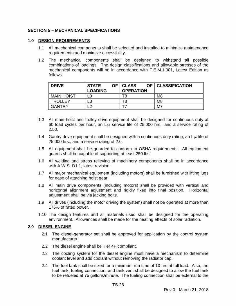
1.2 The mechanical components shall be designed to withstand all possible combinations of loadings. The design classifications and allowable stresses of the mechanical components will be in accordance with F.E.M.1.001, Latest Edition as follows:
DRIVE STATE OF
LOADING CLASS OF OPERATION
CLASSIFICATION
MAIN HOIST L3 T8 M8 TROLLEY L3 T8 M8 GANTRY L2 T7 M7
1.3 All main hoist and trolley drive equipment shall be designed for continuous duty at
60 load cycles per hour, an L10 service life of 25,000 hrs., and a service rating of 2.50.
1.4 Gantry drive equipment shall be designed with a continuous duty rating, an L10 life of 25,000 hrs., and a service rating of 2.0.
1.5 All equipment shall be guarded to conform to OSHA requirements. All equipment guards shall be capable of supporting at least 250 lbs.
1.6 All welding and stress relieving of machinery components shall be in accordance with A.W.S. D1.1, latest revision.
1.7 All major mechanical equipment (including motors) shall be furnished with lifting lugs for ease of attaching hoist gear.
1.8 All main drive components (including motors) shall be provided with vertical and horizontal alignment adjustment and rigidly fixed into final position. Horizontal adjustment shall be via jacking bolts.
1.9 All drives (including the motor driving the system) shall not be operated at more than 175% of rated power.
1.10 The design features and all materials used shall be designed for the operating environment. Allowances shall be made for the heating effects of solar radiation.
2.0 DIESEL ENGINE 2.1 The diesel-generator set shall be approved for application by the control system
manufacturer. 2.2 The diesel engine shall be Tier 4F compliant. 2.3 The cooling system for the diesel engine must have a mechanism to determine
coolant level and add coolant without removing the radiator cap. 2.4 The fuel tank shall be sized for a minimum run time of 10 hrs at full load. Also, the
fuel tank, fueling connection, and tank vent shall be designed to allow the fuel tank to be refueled at 75 gallons/minute. The fueling connection shall be external to the
TS-27 Rev 0 - March 21, 2018
engine house. 2.5 Diesel engine exhaust shall be ducted at least 2m above the top of the Crane.
The exhaust pipe shall run up the gantry leg to the maximum elevation. Pipe material shall be muffler grade stainless steel. The end on the exhaust pipe shall be horizontal. The exhaust pipe shall have a pocket at its lowest elbow into which condensation can collect. This pocket shall be provided with a drain. Maintenance access shall be provided around the silencer assembly. The exhaust pipe shall be insulated wherever it may be accidentally touched by personnel during crane operations or maintenance activities.
2.6 The silencer shall be of the heavy-duty, hospital rated with welded muffler grade stainless steel, spark-arresting type, with welded construction throughout.
2.7 A diesel engine kill switch shall be provided in an SCPA approved location outside of the diesel enclosure. A battery disconnect for OSHA lockout purposes shall be provided in the engine house.
2.8 The Crane shall include an adequately sized continuous duty controlled load bank to provide a regenerative load level as a function of regenerative load on the diesel engine-alternator. A solid-state controller shall be used to provide stepless control of regenerative power absorption without contactors. The load bank rating shall be a minimum of the amount of regenerative power (i.e., based on decelerating rated load while lowering and decelerating the trolley, both simultaneously at maximum speed and maximum deceleration rates) which exceeds 50% of the diesel engine friction power rating. Controls shall sense the load and connect the load bank to absorb regenerated power whenever that power exceeds 50% of the diesel engine friction power rating, and shall disconnect the load bank whenever the load is less than 50% of the diesel friction power rating.
2.9 The load bank shall be installed in a suitable well-ventilated, weather-protecting enclosure. The load bank shall be cooled by means of natural convection, and shall be suitable for outdoor service, and storage in environmental conditions including high humidity. The enclosure shall provide protection from rainfall, and shall not require opening of louvers for operation. All load bank housing and components shall be stainless steel; resistors shall be punched grid type corrosion resistant steel unless otherwise SCPA approved.
TS-28 Rev 0 - March 21, 2018
3.0 COUPLINGS 3.1 All couplings, except drum couplings, shall be flanged forged steel gear type
couplings with exposed bolts. Drum couplings shall transmit combined shear and torque loads. Elastomeric element couplings shall be restricted to small auxiliary power drives.
3.2 Couplings shall be fitted with fill and drain plugs for re-lubrication. 3.3 All couplings shall be covered with suitable removable cover guards with hinged
openings for lubrication and inspection. Hinged openings shall not be bolted, but shall be of the hood latch type.
4.0 BRAKES 4.1 All brakes shall be:
4.1.1 Spring-applied, hydraulic (thruster) or electrically released disc brakes. 4.1.2 Adjustable. 4.1.3 Furnished with automatic wear compensator with self-centering feature to
equalize pad to disc air gaps. 4.1.4 Furnished with incombustible linings not adversely affected by moisture.
4.2 All brakes shall engage if electrical power to the brake or its actuating device is lost. 4.3 All brakes shall have provisions for manual release. 4.4 All pins in the brake shall be of high strength bronze or stainless steel. 4.5 Electric brakes for motors exposed to the weather shall be fully enclosed in
waterproof housings with an easily removable access cover for adjustment and repair.
4.6 Electric brakes for motors shall be of sufficient capacity to decelerate design loads from full speed, independent of any regenerative braking.
4.7 All brakes shall have adequate thermal capacity for two successive emergency stops under worst case operating condition with operating wind from the most severe direction
4.8 As a minimum, there shall be two main hoist brakes, with each individual brake having torque rating no less than 100% of the torque required to raise full rated load at rated speed.
4.9 Each trolley motor shall have a brake with torque rating at least 125% of rated motor torque. If only one or two trolley motors, each shall have a brake with torque rating at least 200% of rated motor torque.
4.10 Each gantry motor shall have a brake with torque rating no less than 250% of rated motor torque.
4.11 Aluminum is not acceptable for disc material.
5.0 GEARING 5.1 All gearing shall be hobbed helical with an overlap ratio not less than 1.5 and shall
be contained in heavy rigid, totally enclosed oil-bath gear reducer cases. Spur

TS-29 Rev 0 - March 21, 2018
gearing shall not be used. 5.2 Gearing shall be suitably hardened for the intended service. 5.3 Gear reducer cases shall be:
5.3.1 Flanged and horizontally split on the common shaft centerlines. 5.3.2 Horizontally mounted. 5.3.3 Provided with lifting lugs on upper and lower sections. 5.3.4 Fabricated or cast steel. 5.3.5 Equipped with filtered vents, weatherproof vent caps, inspection covers, oil
level site glasses, thermometers, and drains with magnetic plugs (valves shall not be used).
5.4 Main hoist, trolley, and gantry drive gearing shall be designed and rated in accordance with the latest applicable standards issued by AGMA and design loads as per F.E.M. Factors contained in the F.E.M. standards shall be conservatively selected according to the prevailing conditions in RTG Crane operations.
5.5 Main hoist, trolley and gantry gearing, including gear strength and stress, shall be designed and rated in accordance with the latest applicable standards issued by ISO 6336 (SFS 4790) and AGMA and design loads as per F.E.M. 1.001, latest edition.
5.6 Gearing and bearing design loads will be based on F.E.M. 1.001 (latest edition) combined operating conditions which include inefficiency, 50% operating wind load, and specified speeds and acceleration/deceleration rates.
5.7 Maximum operating loads for main hoist motion will be calculated per F.E.M. 1.001, latest edition, section 2.6.4.1. Maximum loads for horizontal motions (gantry and trolley) will be calculated per F.E.M., section 2.6.4.2. Amplifying coefficient will be per F.E.M requirements for state of loading, class of operation, and classification specified in Section 5, Paragraph 1.2.
5.8 Mean load for calculating reducer gear and bearing life/size will be per F.E.M, section 4.2.1.2 calculated by modifying the appropriate maximum operating load by the cube root of the maximum load spectrum factor for the specified state of loading. The load spectrum factor will be per F.E.M. requirements for state of loading, class of operation, and classification specified in Section 5, Paragraph 1.2 (i.e., cube root of load spectrum factor .25 for state of loading L2, cube root of load spectrum factor .5 for state of loading L3).
5.9 Safe working load for maximum and operating load calculations will be based on continuous duty cycle rating of 50 LT.
5.10 Gear stress calculations and allowable stresses will be based on AGMA standards (AGMA 21.01 latest edition).
5.11 Allowable stresses at FEM combined operating loads will be per AGMA with service factors as below: Main hoist and trolley: Durability: 1.5
Bending: 1.5 * 1.5 or 2.25. Gantry: Durability: 1.0
Bending: 1.5 * 1.0 or 1.5.
TS-30 Rev 0 - March 21, 2018
5.12 Bearing life will be based on the appropriate mean operating load with design life
equal to the maximum value of the range specified by F.E.M. 1.001 for the class of utilization specified (i.e., 25,000 hours for T7).
6.0 DRUMS 6.1 Drums shall be:
6.1.1 Fabricated or centrifugally cast steel with stub shafts with double end diaphragms.
6.1.2 Stress relieved before machining. 6.1.3 Statically balanced with wire rope clamps in place after machining by adding
welded-on weights. 6.2 Wire rope grooves shall be surface hardened to HB 321 minimum. Drums shall
have a pitch diameter not less than 30 rope diameters. Wire rope grooves shall be machined. Groove depth shall be a minimum of 38% of wire rope diameter, with a slight radius on groove edges. Drum shell thickness beneath the grooves shall be determined by strength analysis, but not less than 0.75 as thick as the wire rope diameter unless otherwise approved by Engineer.
6.3 Wire rope shall be spooled in one layer, with three unclamped full wraps remaining in the grooves when the rope for normal operation lift or travel is payed out, with a minimum of one (1) extra full groove shall be provided to accommodate rope stretch
6.4 Wire rope shall be anchored to drums by at least three clips. All devices holding the wire rope to the drum shall be accessible and easily removed with the drum in one position.
7.0 WIRE ROPES 7.1 Wire rope shall be:
7.1.1 Extra improved plow steel with independent wire rope core. 7.1.2 Inspected and tested by an independent testing laboratory. 7.1.3 Internally and externally pre-lubricated at the factory by the wire rope
manufacturer prior to delivery. 7.1.4 6 x 37 bright construction for the main hoist. 7.1.5 In English-system dimensions, not metric. 7.1.6 Supplied with a safety factor of 6.0 for the main hoist and 5.0 for all other
applications. 7.1.6.1 Rope safety factors for twin twenty operation shall be considered
with twin twenty eccentric loads. A weight of 28,000 pounds (minimum) shall be assumed for the spreader.
7.2 Each rope is to be supplied with full test certification. 7.3 Rope lay shall be selected to minimize rotation under load. 7.4 Dead end wire rope terminations shall be by open swedged sockets with a 2 inch
pin.
TS-31 Rev 0 - March 21, 2018
7.5 UHMW buffers shall be provided for protection of wire rope at all points where contact with crane structure could occur.
7.6 All equipment necessary to perform wire rope changes shall be mounted on the trolley.
8.0 SHEAVES AND ROLLERS 8.1 Wire rope reeving shall avoid reverse bending and the development of kinks and
minimize the size and number of rub blocks and guide rollers. 8.2 Sheaves shall be:
8.2.1 Equipped with anti-friction bearings and properly sized and installed seals to prevent moisture or dust from entering the bearings.
8.2.2 Machined from rolled or forged steel or rolled steel welded construction with die forged rim per AISE No. 6.
8.2.3 Furnished with wire rope grooves surface hardened or hard faced to HB 321 minimum to a minimum depth of 5mm.
8.2.4 Furnished with a minimum sheave diameter of 30 rope diameters. 8.2.5 Furnished with substantial close-fitting continuous peripheral plate guards
around the rope contact area which prevent the rope from coming out of the sheave groove under any condition of slack or bouncing rope.
8.3 Fleeting sheaves shall not be used. 8.4 The fleet angles of wire ropes shall not exceed the following:
8.4.1 The angle to the axis of the drum grooving at the point of tangency: 2½ Degrees.
8.4.2 To sheaves with fleet angle or where the varying angle does not pass through zero degrees near midpoint of travel: 2½ Degrees.
8.4.3 To sheaves with fleet angle varying approximately equally either side of zero degrees during normal travel: 3 Degrees.
8.5 The fleet angle between trolley and headblock sheaves may exceed 3 degrees when the headblock is within 3 m of its highest position, but shall not exceed 3½ degrees.
9.0 BEARINGS AND SEALS 9.1 Bearings shall be:
9.1.1 Anti-friction type. 9.1.2 In millimeter sizes. 9.1.3 Conform to AFBMA/ISO for ratings and dimensions. 9.1.4 Designed for an L10 life of 25,000 hrs minimum. 9.1.5 Sealed by caps or spring loaded lip-garter type seals, except for gear reducer
bearings. 9.1.6 Supplied with pressure grease lubrication.
TS-32 Rev 0 - March 21, 2018
9.2 Where shafts or axles are fixed, bushings constructed of high strength bronze with annular lube passages in both pins and bushings shall be provided. Bushing pressures shall be limited to 4,000 psi.
9.3 Seals shall be in millimeter sizes. 9.4 All bearings and seals shall be manufactured as part of regularly scheduled
production runs and in stock at commercial distributors doing business in the vicinity of Charleston, South Carolina.
9.5 Cast iron pillow blocks or bearing cartridges shall not be used. 9.6 The base of each bearing pedestal shall be machined and shall bear against a
machined surface. 10.0 MAIN FUNCTION DRIVE ARRANGEMENTS
10.1 The proposal shall include arrangement drawings and operational descriptions of the main hoist and trolley drives, details to include capacities of the motors and brakes.
10.2 The proposal shall include arrangement drawings and operational descriptions of the gantry drive, details to include capacities of the motors and brakes, differential steering, cross travel and crane pivot (rotation about the crane center point).
TS-33 Rev 0 - March 21, 2018
SECTION 6 – MISCELLANEOUS EQUIPMENT SPECIFICATIONS 1.0 DESIGN REQUIREMENTS
1.1 The design features and all materials used shall be designed for the operating environment. Allowances shall be made for the heating effects of solar radiation.
2.0 OPERATOR’S CABIN 2.1 The prime consideration in the design of the operator’s cabin and the operator's
chair and consoles shall be the operator's safety, comfort, and efficiency. The operator’s cabin, the operator’s chair and control consoles, control devices, and their locations shall be subject to the Owner’s approval. An Operator’s Cab arrangement drawing shall be provided with the proposal.
2.2 The design and construction of the operator’s cabin shall meet the following as a minimum: 2.2.1 Adequate size and design strength for an operator and two (2)
observers/trainees. 2.2.2 Double walled steel construction that is fire resistant and weather proof under
all weather conditions. 2.2.3 All exterior welds shall be continuous. 2.2.4 The space between the double floor plates shall be used for electrical wiring.
The upper floor plate shall be vinyl covered and bolted to provide access to the electrical wiring.
2.2.5 Sound and thermal insulation shall be provided between the double layers of the walls and ceiling.
2.2.6 Framing shall be securely fastened to the trolley by means of high strength structural fasteners. Stop blocks shall be provided to hold the cabin if the bolts securing the cabin to the trolley fail.
2.2.7 Designed such that there are no penetrations through the roof. 2.2.8 A large sun shade/drip rail shall be provided over the main front and side
windows. Drip rails shall be provided over other windows. 2.2.9 Cab shall be well-ventilated.
2.3 The windows of the operator’s cabin shall meet the following as a minimum: 2.3.1 Provide the operator with full visibility of all crane operations. 2.3.2 Glazing shall be replaceable from inside the cab. 2.3.3 All vertical and sloping glass shall be tinted safety glass. 2.3.4 Windows on the front and sides of the cab shall be openable for ventilation. 2.3.5 A fixed full length and uninterrupted window shall be provided in the floor at
the operator's feet. This window shall be rated to support an operator’s weight. It shall have an interior metal grid guard which does not unduly limit the operator's visibility and is hinged at the front of the cabin to open inward to allow window cleaning.
2.3.6 One auxiliary window behind and to one side of the operator’s chair shall be provided for an observer. It shall have the same strength requirements as
TS-34 Rev 0 - March 21, 2018
the main window. It may be guarded on the exterior of the operator’s cabin. 2.4 The operator’s cabin shall be equipped with a thermostatically controlled heater/air
conditioner which will maintain conditions of 65-80oF and less than 50% relative humidity under the operating environment. A standard, heavy duty, wall mounted unit is preferred. The unit shall be controlled by a wall mounted thermostat – no remote control.
2.5 Owner-approved directional defrost/de-fog provisions shall be provided for the sighting windows.
2.6 Window wipers and washers shall be installed on all sighting windows. 2.7 The operator’s chair shall have the following features as a minimum:
2.7.1 A high-back heavy-duty fabric-covered seat with:
• a retractable seat belt
• lumbar support
• padded armrests
• adjustable back angle
• 6-inch fore and aft adjustment
• 6-inch height adjustment 2.7.2 Capable of pivoting under all adjusted seat and console positions
unobstructed with an operator in the seat. 2.7.3 Control consoles that have the following adjustments which are independent
of the seat adjustments:
• fore and aft over a 6-inch range
• vertically 3-inch 2.8 A shelf shall be provided close the operator’s chair, with a 110V outlet, so that the
owner may install a radio for port communications. 2.9 The Crane’s capabilities (load ratings, speeds, etc.) shall be on an etched or
engraved stainless steel plate permanently attached to a wall. This nameplate shall be easily readable by an operator while operating the Crane.
3.0 HEADFRAME 3.1 The headframe shall be equipped with at least two devices meeting OSHA
requirements for tying off fall protection equipment: one in the center of the far side and one in the center of the near side.
3.2 The headframe shall consist of a structural frame with two sets of hoist blocks and guarded sheaves that are permanently reeved into the hoist system. Headframe arrangement shall generally be in conformance with the existing Owner headframes.
3.3 The headframe shall be designed for quick manual connection to the spreader bar. The headframe twistlocks shall have a fail-safe mechanism that shall require the manual release of a pin before the twistlocks can be rotated.
3.4 The headframe shall meet all of the structural specifications of Section 3.
TS-35 Rev 0 - March 21, 2018
4.0 SPREADER BAR 4.1 One spreader bar shall be furnished for each RTG Crane. 4.2 The spreader bar shall meet the following general requirements as a minimum:
4.2.1 Capable of handling single 20 ft. or 40 ft. or 45 ft. containers. 4.2.2 Capable of handling two 20 ft. containers with a separation of up to 5 ft. and
a height difference of at least 6 inches. (Separating twin twenty spreader not included in the base proposal.)
4.2.3 Expand and retract between the 20 foot and 40 foot positions in no more than twenty (20) seconds.
4.2.4 Expand and retract between the 20 foot and 45 foot positions in no more than thirty (30) seconds.
4.2.5 Total weight not to exceed fourteen (14) short tons (28,000 pounds). 4.2.6 Minimum safe working load of 50 long tons. All proposals shall specify the
design fatigue cycle rating at the safe working load. 4.2.7 Capable of handling the following eccentric loads:
• One 32.5 LT 20 ft. Container ± 10% longitudinally and 10 inches transversely with one empty 20 ft. container lifted together, with and without the maximum 5 ft. separation of the spreader bar. (Separating twin twenty spreader not included in the base proposal.)
• One 45 ft. container with 50LT load at 55 inches longitudinal eccentricity and 10 inches transverse eccentricity.
4.2.8 A system to reduce or minimize impact shock while latching or landing containers is desirable. All proposals shall specify what type of system, if any, will be used and the cost differential to exclude the proposed system.
4.2.9 Lugs installed to accept and a means to automatically detect engagement of overheight attachments currently used by the Owner.
4.3 The spreader bar shall meet the following structural requirements as a minimum: 4.3.1 The spreader bar shall meet all of the structural specifications of Section 3. 4.3.2 The connection to the headframe shall be via twistlocks and shall be
compatible with existing SCPA RTG Cranes at the Wando Welch Terminal. 4.3.3 Cabling, switches, valve assemblies, coils, and relays shall have only the
manufacturer’s coating. These items shall not be painted with the spreader. 4.3.4 Ladders shall be mounted on the spreader for access to the headframe and
shall align with existing Owner headframe ladders and/or man baskets. The ladders shall be tapered or curved in at bottom to prevent snagging umbilical cable when it falls out of the basket and shall be welded to the spreader at both ends of the ladders.
4.4 The spreader bar shall meet the following electrical requirements as a minimum: 4.4.1 The spreader bar shall meet all of the electrical specifications of Section 4
except that the spreader bar I/O shall be 120 VAC. 4.4.2 The electrical/electronic connections to the headframe shall be compatible
TS-36 Rev 0 - March 21, 2018
with existing SCPA cranes at the Wando Welch Terminal. 4.4.3 Junction Boxes shall:
• Shall be 316 stainless steel, NEMA 4X with quick release latches
• Be mounted on shock absorbers.
• Have no finish other than the manufacturers finish.
• Be oriented such that the main door is not on the top horizontal surface.
• Not contain wireways. 4.4.4 Each twistlock shall have a separate lock and unlock proximity switch; both of
which shall be triggered by the twistlock. 4.4.5 Center Gap Detection with multiple sensors:
• Shall be a proven system. The proposal shall identify locations where the proposed system is installed and has been functioning for at least one (1) year. These locations will preferably be in the United States.
• Sensors shall be rated for weather proof operation (epoxy filled) and have quick disconnect plugs.
• The red corner seat light on the light bar shall flash to indicate a center gap has been detected.
4.4.6 The numbering sequence of cabling and wiring shall be consistent with current Owner spreader bar cabling and wiring schemes.
4.4.7 If provided, the hydraulic pump motor:
• Shall be compatible with the spreader hydraulic pump motor cabling and protective devices on existing SCPA cranes at the Wando Welch Terminal.
• Frame size shall be compatible with existing Owner spreader hydraulic pump motors.
4.4.8 The expand and retract system shall be self correcting and capable of regulating to within one quarter (1/4) inch of the selected position. If an encoder is used to perform this function, it shall have a backup system that utilizes proximity switches.
4.4.9 The spreader indicating light bar shall be from an Owner-approved manufacturer, use LEDs, and be oriented such that the green (unlock) light is on the operator’s left and the amber (lock) light is on the operator’s right as viewed from the operator’s seat in the cab.
4.5 The spreader bar shall meet the following mechanical requirements as a minimum: 4.5.1 The spreader bar shall meet all of the mechanical specifications of Section 5. 4.5.2 Each corner shall be equipped with an aligning arms meeting the following
requirements as a minimum:
• Capable of operation in far or near pairs or simultaneous operation of all four, at the operator's option.
• Provide a minimum of 6 in. of gather at each corner in each direction.
TS-37 Rev 0 - March 21, 2018
• Extend along the sides of the container a minimum of 9 in. in both directions in the down position.
• Rotate through the fully raised and fully lowered positions in not more than five (5) seconds.
• Be of a “break away” type. A safety chain shall be installed between the section of the aligning arm that breaks away and the section that remains. This safety chain shall not be attached to the splice plate bolts that join the two sections of the aligning arm.
• Actuation shall be by hydraulic roto motors or, if an all electric spreader is provided, by electric motors.
• The gearbox shall develop a minimum of 20790 in/lbs. 4.5.3 Full 90o rotation of twistlocks shall take no more than one (1) second. 4.5.4 Double action cylinders with rod support or, if an all electric spreader is
provided, electric motors shall be used for the twistlocks where ever practical. 4.5.5 If used, the hydraulic system:
• Shall be installed on the spreader.
• Operating pressures shall be specified in the proposal.
• Shall meet all of the hydraulic system specifications of Section 6. 4.5.6 The hose and cable guide:
• Shall be riveted, not snap in type.
• Shall mount on the side of the spreader and not the bottom rail.
• All hydraulic hoses in the guide shall have connections at either end of the guide.
4.5.7 The expand and retract mechanism:
• Shall be chain or belt driven. The use of hydraulic cylinders to expand from the 40 foot position to the 45 foot position will be considered. The proposal shall identify any hydraulic cylinders used to expand and retract the spreader.
• Shall have reinforced shock absorbers on the drive chain/belt.
• Shall use a hydraulic motor or, if an all electric spreader is provided, an electric motor. The cross port relief shall be mounted on this motor.
4.5.8 No ship cell Guide Rollers will be accepted.
5.0 ANTISWAY SYSTEM 5.1 The antisway system may be electrical or mechanical but cannot use hydraulics.
Functional description and arrangement drawings shall be provided with the proposal.
6.0 DAVIT 6.1 An electric rope hoist davit crane of appropriate capacity (1 ton minimum) and
location to handle routine removal of equipment located on or above the trolley shall be provided.

TS-38 Rev 0 - March 21, 2018
7.0 HYDRAULIC SYSTEMS 7.1 The use of hydraulics or hydraulic systems should be avoided – and may only be
used with Owner approval. Any proposed hydraulic systems shall be identified in the proposal.
7.2 Hydraulic systems shall conform to JIC Hydraulic and Electrical Standards for Industrial Equipment.
7.3 Hydraulic systems shall be rated for two and one half (2½) times the system operating pressure with no component used in excess of the original manufacturer's regular catalog rating. However, system pressure shall not exceed 2000psi in actual operation.
7.4 The use of accumulators shall be minimized. If used, accumulators shall have an isolation valve which can be locked.
7.5 All components shall have over-pressure protection, designed to relieve at least 110% of the hydraulic pump’s maximum flow capacity.
7.6 Piping shall not be used to support valves or equipment. Suitable supports shall be provided. Equipment and components shall be "through-bolt" and shock mounted with corrosion resistant fasteners. Blind tapped bolt holes shall be avoided.
7.7 Plastic hose shall not be used. Tapered pipe thread connections shall be avoided wherever possible.
7.8 Systems shall have adequate filtration to remove particles 10 micron or greater in size (main line) and 3 micron or greater in size (side stream). Filter elements shall be spin-on and readily accessible during system operation. Filters employing earth or clay are not acceptable. Automatically switched dual filters shall be used. Filters shall be sized for the maximum flow encountered in operating conditions at the highest viscosity and the lowest temperature. Indicators shall be provided on filters to indicate when the filter needs changing.
7.9 Reservoirs shall be made of 316 stainless steel, and shall be of sufficient capacity to allow for small losses of hydraulic fluid and for the differential capacity of the operating cylinders. They shall be provided with a suitable filler/air breather incorporating a filter (for both moisture and contaminants), a magnetic drain plug, an oil level site glass, a sample connection, a heater, a temperature indicating device, a low level alarm, and a removable cover, giving full access to any parts inside the tank. Hydraulic pumps and filters shall not be located inside reservoirs.
7.10 Exposed hydraulic equipment shall be suitable for the environmental conditions. Cylinder rods shall be retracted as much as possible when the system is not in use, and shall be chrome plated stainless steel, without boots.
7.11 Hose fittings, tube fittings, and hydraulic plumbing lines shall be 316 stainless steel. 7.12 Where movement is required, flexible hoses with swivel fitting terminations shall be
used. 7.13 Flexible hoses shall be of Wire Braid Reinforced Rubber Hose Type 2. Burst
pressure shall be at least 10,000 psi. Hoses shall be proof tested at 5,000 psi. When in position, the radii of flexible hoses shall not be less than the design bend radii given in JIC Standards. Hoses shall not be more than twenty four (24) inches in length. Stainless steel hydraulic lines and fittings and hydraulic hoses shall not be painted.
TS-39 Rev 0 - March 21, 2018
7.14 All hose connections shall be JIC type and stainless steel. 7.15 Hydraulic fluids suitable for use with all hydraulic systems shall be provided. The
use of hydraulic systems for which Shell Spirax S4 TXM 10Wx30 hydraulic fluid does not meet the original manufacturer’s recommendations shall be approved by the Owner.
7.16 Hydraulic pumps shall be horizontally mounted, piston or gear type, pressure compensated, and have variable displacement.
7.17 All components shall be of standard manufacture. 7.18 Valves shall be subplate mounted with a Viton "O" ring seal on the subplate. Valves
shall have the following stamped on the main body of valve or etched or engraved on an additional nameplate that is affixed to the valve: 7.18.1 Manufacturer's Name 7.18.2 Serial Number 7.18.3 Function Identified
7.19 Solenoid operated valves shall have the following features included: 7.19.1 A neon light or LED to indicate functioning of the solenoid. 7.19.2 Operable by external mechanical means (pencil, screwdriver, etc.) in order to
free sticky valve. 7.19.3 Closed Center Spring Centered. 7.19.4 Plug-in coils.
7.20 Hydraulic circuitry shall have load checks to prevent inadvertent movement should a hydraulic hose fail.
7.21 A schematic of each hydraulic system shall be permanently installed in the vicinity of its control unit. All components in the schematic shall be labeled with a permanently installed label adjacent to the component using the identical nomenclature in the schematic. All schematics and labels shall be made of etched or engraved stainless steel.
7.22 All hydraulic systems shall be provided with a hand pump for use in the event the main pump fails.
7.23 All hydraulic systems shall have a manual dump valve. This valve, when opened, shall depressurize the entire system. To prevent inadvertent operation, the valve’s operator shall be removed and stored adjacent to the valve.
7.24 All hydraulic systems and components shall be provided with adequate access systems to facilitate maintenance activities, in accordance with the requirements of these Specifications.
7.25 All operating parameters and alarms/faults (pressures, temperatures, low level alarm, over temperature, etc.) shall be fed to the PLC for diagnostic purposes.
8.0 LUBRICATION SYSTEMS 8.1 The grease fittings used for motor bearings shall be zirc type fittings made of monel
or stainless steel (Spring Straight Ball Check NAPA number 715-1073 (no substitutes)).

TS-40 Rev 0 - March 21, 2018
8.2 All other grease fittings shall be industrial buttonhead type grease fittings (Standard Type Ball Check NAPA part numbers 715-1115 for 1/8 PT and 715-1116 for 3/8 PT, or equivalent) made of monel or stainless steel.
8.3 Grease fittings shall be readily accessible or shall be remotely piped with stainless steel hydraulic tubing to convenient locations. Remote lubrication lines shall not exceed ten (10) feet in length. Each grease fitting, whether remote or local, shall service only one lubrication point. Each remote grease fitting shall be clearly labeled with a stamped or engraved stainless steel label to indicate which mechanism it serves.
8.4 The Contractor shall furnish lubricants in accordance with the original manufacturer's recommendations in sufficient quantities for initial lubrication of the Crane(s). The Contractor shall also perform the initial lubrication of all components in accordance with the original manufacturer’s recommendations
8.5 The following is a list of lubricants currently used by the Owner. Equipment or components for which these lubricants do not meet the original manufacturer’s recommendations shall be identified in the proposal. 8.5.1 Open gear lubricant: Lubrication Engineers Pyroshield 5180. 8.5.2 Gear reducer oil: Shell Omala S4 GX. 8.5.3 Grease: Mystic JT-6 Hi-Temp Red Grease 2. 8.5.4 Wire rope lubricant: Lubrication Engineers Wirelife Low Tox Penetrating
Lubricant 2011.
9.0 COMMUNICATION SYSTEM 9.1 A telephone systems with stations between the operator's cabin, ground level at
truck lane side, and Electrical House shall be provided. 9.2 A public address system and warning horn shall be provided in the operator’s cabin.
10.0 EQUIPMENT ENCLOSURES 10.1 All equipment enclosures shall be made of 316 stainless steel unless specifically
addressed in another section of these specifications. 10.2 Equipment enclosures shall have hinged doors capable of being opened to fully
expose and allow removal of equipment mounted inside. Latches shall be provided to secure all doors when opened for servicing; and such latches shall be adequate to secure doors in high winds.
11.0 SPREADER BAR POSITION CONTROL 11.1 A mechanism to adjust the skew of the spreader bar to plus or minus five degrees (±
5°) shall be provided. 11.2 A mechanism to adjust the trim of the spreader bar to plus or minus five degrees (±
5°) shall be provided. 11.3 A mechanism to side shift the spreader bar shall be provided with movement twelve
inches (12 inches) from center in both directions. 11.4 Each mechanism shall be provided with a brake or other positive means to maintain
the selected spreader position under all operating conditions. These mechanisms shall be independently powered and independently controlled from the operator's cabin.
TS-41 Rev 0 - March 21, 2018
11.5 The proposal shall include a full operational description (with arrangement drawings) of the spreader bar position control.
12.0 ENERGY CHAIN SYSTEM 12.1 The energy chain system shall be located well away from the hoist wire ropes to
prevent "cable slap." 12.2 Power and control wiring shall be run in Owner-approved flexible insulated cables,
via an Owner approved energy chain system to junction boxes on the trolley. The system shall be suitable for operation in high winds with operating speeds and accelerations specified. Energy chain cables shall include fiber optic cables if required by the control system manufacturer for communications.
12.3 The Energy Chain System shall be an Owner-approved supplier. The Cable trough, Energy Chain hardware, all wiring and supervision of installation shall be supplied by the Energy Chain System Manufacturer. The system shall be designed for RTG application; engineered and installed for ease of maintenance and repair of the cable troughs, links and cables. The system design and materials shall consider the stringent container crane operational requirements as well as the harsh environmental conditions of Charleston, South Carolina. Special attention shall be paid to UV resistance.
12.4 The system shall consist of a cable trough, cable carrier (energy chain) and cables. The trough system must be made 304 stainless steel or other Owner-approved material; resistant to the marine environment. All fasteners shall be stainless steel with all nuts being self-locking.
12.5 The trough joint joining kits must be heavy duty with reinforced installation support angles and trough must have UHMW glide bars for travel beyond the fixed bracket.
12.6 The chain radius must be double of the minimum bending radius of the biggest cable. (for example: cable diameter 20mm, minimum bending radius 5x outer diameter =100mm, minimum chain radius 200mm). The chain must not have glide shoes or removable pivoting pins. But, the system must have a floating tow-arm provided by the system manufacturer.
12.7 The side link of the chain and the cross-bar material must be of the same material and must have rollers integrated into the link. The bearings for the rollers must be stainless steel and pre-lubricated with an Owner-approved marine grade grease.
12.8 All power and control cables shall be run in flexible, insulated, cable conductors from junction boxes on the landside cables and of the main girder crane frame via an energy chain system to junction boxes on the trolley. The system shall consist of heavy-duty, high performance energy chain allowing the conductor length to collapse and expand.
12.9 The cables shall be designed for use in a cable carrier, rated for outdoor use, and shall be provided by the system manufacturer or Owner-approved equal. The complete energy chain/cable package shall be provided by the system manufacturer. All cables shall be blocked in place so as not to overlap or slip in the links.
12.10 The cables supplied shall include a minimum quantity of 15% spare conductors. 12.11 Spare conductors are required per cable. If the cable provided does not have
the required amount of minimum spare conductors, an additional cable shall be provided. (This requirement also applies to spare fiber optic cores/cables in the
TS-42 Rev 0 - March 21, 2018
energy chain.) 12.12 Cable separation requirements of Section 4.0 shall be met. 12.13 Any controls (faults, alarms, interlocks, etc) associated with the system shall be
fully integrated into the control system by the Control System Supplier in order to provide complete control and diagnostics. The Control System Supplier shall review and approve the design of the system to ensure communication problems are eliminated or reduced to an acceptable level and complete control and diagnostics are provided.
12.14 Fiber-Optic Cable and low power level shielded or twisted pairs shall run in separate UL listed cables and shall terminate at both ends of the system in separate junction boxes from the power and control circuits.
12.15 Service platforms shall be provided on the RTG to permit inspection, repair and/or replacement of the system components. Access shall be provided to the fixed bracket location on the trolley and on the girder.
13.0 CCTV SYSTEM 13.1 A CCTV system shall be provided and installed on the RTG for the operator to
monitor and check the ground level container handling operations and diesel side gantry travel runway in both directions. As a minimum cameras shall be mounted: one on each bogie (corner) and one or two on the truck lane – providing a view of the entire driver side of the container including the corner twistlocks..
13.2 The monitor (21 inch minimum) shall be a split screen type showing all camera views simultaneously. The monitor shall be in the operator’s cabin and positioned such that it does not obstruct the operator’s view of the truck lane yet is visible without having to look up and away from the truck lane.
13.3 The CCTV system shall consist of industrial color cameras with low light sensitivity, one color monitor, image splitters, manual and sequential video switcher, amplifiers, control console, etc.
13.4 Details of the proposed system shall be provided with the proposal.
14.0 TRUCK PROTECTION SYSTEM 14.1 An SCPA approved system shall be provided to protect the Crane and truck from
lifting a truck (chassis) during container handling operations. Details of the proposed system shall be provided with the proposal.
15.0 AUTO STEERING 15.1 A DGPS based auto steering system shall be provided which is capable of
accurately controlling gantry differential steering at any gantry speed with loaded or unloaded trolley at any position in its operating travel range. The system shall accommodate any changes in horizontal or lateral slope of the runways to maintain accurate auto steering (minimum accuracy of +/- 50mm). The price shall include
TS-43 Rev 0 - March 21, 2018
supply and installation of equipment for the Crane(s) plus the supply of any required facility-side equipment (base stations). SCPA will install any required facility side (base station) equipment. The system shall interface with the existing auto-steering/yard management system in use at SCPA.
15.2 While in manual steering mode the system shall monitor the position of the Crane and provide a warning alarm if the Crane is out of position (adjustable).
15.3 Details of the proposed system shall be provided with the proposal.
16.0 GANTRY ANTI COLLISION STSTEM 16.1 A gantry anti-collision system shall be provided which is capable of detecting any
obstacles in the gantry runways and potential stack collisions. The runway system shall be radar based.
16.2 Details and description of the system to be provided with the proposal.
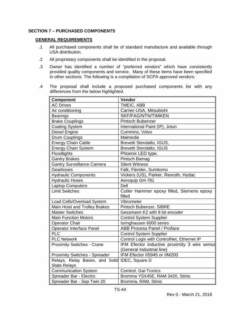
TS-44 Rev 0 - March 21, 2018
SECTION 7 – PURCHASED COMPONENTS
GENERAL REQUIREMENTS .1 All purchased components shall be of standard manufacture and available through
USA distribution. .2 All proprietary components shall be identified in the proposal. .3 Owner has identified a number of “preferred vendors” which have consistently
provided quality components and service. Many of these items have been specified in other sections. The following is a compilation of SCPA approved vendors:
.4 The proposal shall include a proposed purchased components list with any differences from the below highlighted.
Component Vendor AC Drives TMEIC, ABB Air conditioning Carrier-USA, Mitsubishi Bearings SKF/FAG/NTN/TIMKEN Brake Couplings Pintsch Bubenzer Coating System International Paint (IP), Jotun Diesel Engine Cummins, Volvo Drum Couplings Malmedie Energy Chain Cable Brevetti Stendalto, IGUS, Energy Chain System Brevetti Stendalto, IGUS Floodlights Phoenix LED type. Gantry Brakes Pintsch Bamag Gantry Surveillance Camera Silent Witness Gearboxes Falk, Flender, Sumitomo Hydraulic Components Vickers (US), Parker, Rexroth, Hydac Hydraulic Hoses Aeroquip GH-781 Laptop Computers Dell Limit Switches Cutler Hammer epoxy filled, Siemens epoxy
filled Load Cells/Overload System Vibrometer Main Hoist and Trolley Brakes Pintsch Bubenzer, SIBRE Master Switches Gessmann K2 with 8 bit encoder Main Function Motors Control System Supplier Operator Chair Isringhausen 6000 series Operator Interface Panel ABB Process Panel / Proface PLC Control System Supplier PLC Network Control Logix with ControlNet, Ethernet IP Proximity Switches - Crane IFM Efector inductive proximity 3 wire senso
(General Industrial line) Proximity Switches - Spreader IFM Efector II5945 or IIM200 Relays, Relay Bases, and Solid State Relays
IDEC, Square D
Communication System Comtrol, Gai-Tronics Spreader Bar - Electric Bromma YSX45E, RAM 3420, Stinis Spreader Bar - Sep Twin 20 Bromma, RAM, Stinis

TS-45 Rev 0 - March 21, 2018
Component Vendor Spreader Cable Prysmian Switchgear Control System Supplier Terminal Blocks Entelec UPS Units Powerware Walkway Lights Phoenix LED Cube type Wire Rope Wireco (Macwhyte), Bridon Gantry Warning Bell Federal Signal SelecTone 300GC-120

TS-46 Rev 0 - March 21, 2018
SECTION 8 – QUALITY CONTROL, TESTING AND ACCEPTANCE 1.0 SCOPE
1.1 It shall be the responsibility of the Contractor to establish a Quality control Program. This program shall follow the guidelines established hereinafter. The Quality control Program is to include, but is not limited to providing, a qualified supervisor, qualified inspectors, required inspections, and records. This program shall assure the Owner that all materials and/or work are supplied and/or conducted in accordance with the applicable codes, approved shop drawings, this Specification, and proper work practices for the various trades.
1.2 At least one of the Contractor's quality control employees shall be assigned
full time to each location where components are fabricated. Components such as electrical motors and gear reducers should be tested and accepted by the Contractor at the manufacturer's plant, or the location have a pre-qualified quality control system certified by SCPA.
1.3 All quality control shall be conducted at the Contractor's expense, including
testing, adjustment, and repair. 2.0 GENERAL
2.1 Upon the award of this Contract, the Contractor shall submit a detailed program proposal. This proposal shall include approach, schedule, and personnel resumes. Resumes are to include name, title, specialty, and ex-perience. Acceptance of quality control inspectors will be pending the review of resumes. Inspection of multiple trades will be allowed only if these qualifications are reflected in the resume.
2.2 All non-destructive testing, materials testing, and bolt torque testing shall be
conducted by an independent testing firm (Subcontractor), acceptable to the Engineer, or by an acceptable testing agency accredited by the certifying agency in the country of fabrication. The Contractor shall also be allowed the option of utilizing a Subcontractor for the entire Quality Control Program. Acceptance of Subcontractors will be subject to the same criteria stated above.
2.3 The Owner reserves the right to retain independent inspection laboratories
and/or engineers to insure strict compliance with the terms of the Contract Documents as well as local regulations required by Government laws. The Contractor shall keep the Owner and the Engineer fully informed as to the general progress of the work and shall notify the Owner and Engineer, well in advance, when any item of equipment, component, or subassembly is ready for testing. If any subassembly should be assembled by the Contractor without such notification, or without allowing the Owner or Engineer reasonable opportunity to inspect all of its components, the Owner will have the right to require the Contractor to remove or disassemble the assembly in whole or in part, so that proper inspection of its components can be made.

TS-47 Rev 0 - March 21, 2018
The Contractor shall bear the cost of such removal or disassembly and no extension of time to the Contract completion date for this work will be allowed.
2.4 The Owner’s inspectors shall have free access to the mills or shops of the
Contractor and his subcontractors or vendors, and shall be supplied with all drawings and specifications required to carry out the inspection. This independent inspection does not relieve the Contractor of his responsibility to carry out his own quality control.
2.5 Any work, materials, or equipment not conforming to these specifications will
be considered defective, whether in place or not, and will be rejected by the Owner’s representative. Work performed from drawings or revisions thereto which have not been signed or initialed by the Contractor's responsible Structural Engineer will not be inspected and will be considered rejected. Refusal of the Owner to exercise such authority shall not impose any responsibility on him, and the Contractor shall remain fully responsible for the completion of his work as specified. Defective work shall be repaired using recognized and established procedures.
2.6 No inspector is authorized to change any provision of the Specification
without written authorization of the Owner or Engineer, nor shall the inspection and approval by the Owner’s representative, or lack of inspection and approval, relieve the Contractor from any requirements of the Contract. Inspection by the Owner’s representative will be performed in such a manner as not to unnecessarily delay the work.
3.0 RECORD KEEPING
3.1 Written record of inspections shall be submitted to the Engineer as required by this Section. Typewritten copies of each required inspection record or report shall be submitted to the Engineer bi-weekly. All inspection forms and reports shall identify job title, contract number, crane number, type of test or inspection, location, comments, date of inspection, and the inspector's signature. Subcontractor's standardized forms will be accepted, if the above stated information is included on them.
3.2 The Contractor shall be required to submit all manufacturer's certificates and
welder certificates in accordance with the General Provisions of this Specification.
3.3 All radiographic film shall be submitted to Owner for review.
3.4 Digital progress photographs shall be taken and submitted to SCPA’s
Engineer each week for the duration of the project. The photographs shall reflect the work being conducted in that particular week. All photographs shall be dated and labeled and forwarded via e-mail to SCPA’s Engineer at least bi-weekly. Two (2) CDs of each submittal shall be required by SCPA’s Engineer.

TS-48 Rev 0 - March 21, 2018
4.0 INSPECTION METHODS
Acceptable inspection methods for this project are as follows:
4.1 Visual Inspection
This type of inspection shall be conducted with the human eye and measuring devices. Verification of proper dimensions, sizes, and work practices shall be accomplished by this type of inspection.
4.2 Non-Destructive Testing
This type of testing will be used to test welds and material for defects. Acceptable methods of non-destructive testing are as follows:
4.2.1 M.T. - Magnetic Particle Testing 4.2.2 Dye Penetrant Testing 4.2.3 U.T. - Ultrasonic Testing 4.2.4 Radiographic Testing (x-ray)
4.3 Electrical Testing
The acceptable instruments for testing electrical installations are as follows:
4.3.1 Calibrated Voltmeter 4.3.2 "Ground Resistance" Test Meter 4.3.3 Light Meter calibrated in footcandles or lux. 4.3.4 Ammeter 4.3.5 Oscilloscope 4.3.6 Control Diagnostic Instrument with Print Out 4.3.7 Megger 4.3.8 High Pot Tester 4.3.9 Sound Pressure Meter (decibels) 4.3.10 Fiber Optic Tester
4.4 Air Test
4.4.1 This test is a pressure test to determine the air and/or watertight integrity of a specified structural member or tank. This test is accomplished by filling a member or tank with air to a pressure of 0.105 kgf/cm2 (1.493 psi). Upon pressurization, a soap solution is applied to all welded joints, fittings and bolted covers. These joints shall then be visually inspected for evidence of leakage, (soap bubbles). If leaks are discovered in screwed or bolted joints, leakage shall be corrected by tightening until all evidence of soap bubbles disappears, but never beyond the allowable bolt torque. If leaks are discovered in welded joints, the pressure shall be released before repair is initiated. Leaking welds shall be corrected by removing the
TS-49 Rev 0 - March 21, 2018
defective portion of the weld by air arc gouging and rewelding. Peen-ing shall not be accepted as a means to correct leakage in welded joints. After the weld has been repaired, the member or tank shall again be pressurized and testing shall be repeated.
4.4.2 The testing rig shall include a calibrated pressure gauge, a positive
closing valve to shut off the air supply, and a relief valve set at a pressure not to exceed the specified test pressure (0.105 kgf/cm2). A calculated head of water to maintain the test pressure is recommended in lieu of a mechanical relief valve.
4.5 Water Hose Test (for cabins)
4.5.1 This test is used to determine the air and/or watertight integrity of
welded joints and fittings in structures which can not be air tested.
4.5.2 This test is accomplished by subjecting the test areas to a spray of water from a 38mm diameter hose at a pressure of 3.45 bar. The nozzle of this hose is to be held a maximum of 3 meters from the test area.
4.5.3 While the test areas are being subjected to the spray of water, the
inspector shall visually inspect the opposite side for evidence of leakage. If leakage is discovered, these shall be corrected by the methods specified under "Air Test" and the test repeated.
4.6 Chalk Test
4.6.1 This test is to serve as an alternative for testing manhole covers for
watertight integrity. This test is to be used on manhole covers where only the covers are required to be tested.
4.6.2 Chalk is applied to the entire sealing flange edge opposite the gasket.
The manhole cover will then be closed and then opened. Upon opening, the inspector shall visually inspect the gasket for a continuous chalk mark. A break in the chalk mark indicates an improper seal. This defect is to be corrected by adjustment.
4.7 Hydrostatic Test (Piping)
4.7.1 This test is to determine the tightness of piping systems. The piping
shall be pressurized with water to one hundred-fifty percent (150%) of the working pressure. Pumps and miscellaneous equipment in the system which are unable to withstand the test pressure are to be isolated using blanks.
4.7.2 Upon attaining the specified test pressure, all joints in the system are
to be visually inspected for evidence of leakage. If leakage is dis-covered, pressure shall be released from the system, and leakage
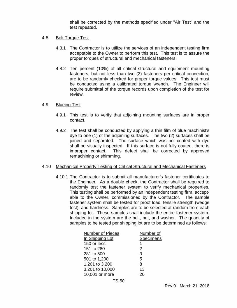
TS-50 Rev 0 - March 21, 2018
shall be corrected by the methods specified under "Air Test" and the test repeated.
4.8 Bolt Torque Test
4.8.1 The Contractor is to utilize the services of an independent testing firm
acceptable to the Owner to perform this test. This test is to assure the proper torques of structural and mechanical fasteners.
4.8.2 Ten percent (10%) of all critical structural and equipment mounting fasteners, but not less than two (2) fasteners per critical connection, are to be randomly checked for proper torque values. This test must be conducted using a calibrated torque wrench. The Engineer will require submittal of the torque records upon completion of the test for review.
4.9 Blueing Test
4.9.1 This test is to verify that adjoining mounting surfaces are in proper
contact.
4.9.2 The test shall be conducted by applying a thin film of blue machinist's dye to one (1) of the adjoining surfaces. The two (2) surfaces shall be joined and separated. The surface which was not coated with dye shall be visually inspected. If this surface is not fully coated, there is improper contact. This defect shall be corrected by approved remachining or shimming.
4.10 Mechanical Property Testing of Critical Structural and Mechanical Fasteners
4.10.1 The Contractor is to submit all manufacturer's fastener certificates to
the Engineer. As a double check, the Contractor shall be required to randomly test the fastener system to verify mechanical properties. This testing shall be performed by an independent testing firm, accept-able to the Owner, commissioned by the Contractor. The sample fastener system shall be tested for proof load, tensile strength (wedge test), and hardness. Samples are to be selected at random from each shipping lot. These samples shall include the entire fastener system. Included in the system are the bolt, nut, and washer. The quantity of samples to be tested per shipping lot are to be determined as follows:
Number of Pieces Number of
In Shipping Lot Specimens 150 or less 1
151 to 280 2 281 to 500 3 501 to 1,200 5 1,201 to 3,200 8
3,201 to 10,000 13 10,001 or more 20
TS-51 Rev 0 - March 21, 2018
4.10.2 If any fastener in a shipping lot is found to be defective, the entire lot is
to be rejected. Records of these tests shall be required by the Engineer for review.
4.11 Supplemental Hardness Testing of Critical Structural and Mechanical
Fastener Systems
In addition to the test specified by Paragraph 4.10 of this Section, the hardness of one random fastener per connection shall be checked. If the hardness is below tolerance for size and grade, hardness tests on the other fastener in the connection shall be performed. If any others are found to be below tolerance, the entire lot of fasteners shall be rejected, and all fasteners replaced.
4.12 Hydrostatic Testing (Tank)
4.12.1 This test is to determine the watertight or oil tight integrity of a tank.
4.12.2 The tank shall be filled with clean, fresh water until it overflows thru the
overflow pipe. This will simulate a full tank. The inspector shall inspect all welded joints of the tank for evidence of leakage. If leaks are discovered, these shall be corrected by the methods specified under "Air Test" and the test repeated. Prior to correcting any welded joint, the tank shall be completely drained of all water.
4.13 Kerosene Test
The roof of the electrical control house, and any cabin with electrical equipment shall be tested by applying a lime solution, which if no kerosene shows will prove the seal.
5.0 FABRICATION INSPECTIONS AND TESTS
5.1 Structural Materials
5.1.1 All structural materials are to be visually inspected for any apparent defects. Size of materials is to be inspected as required, for conformance to design drawings.
5.1.2 All critical structural fasteners are to be visually inspected upon
receipt. In addition to visual inspection, the Contractor shall be re-quired to test fastener systems to verify their mechanical properties as specified.
5.1.3 All welding electrode and flux container labels are to be inspected to
verify compliance.
5.2 Structural Fabrication
5.2.1 Structural members are to be periodically visually inspected throughout fabrication. Dimensional verification of all structural
TS-52 Rev 0 - March 21, 2018
components for compliance with the design drawings and specifications shall be made by the Contractor throughout the fabrication and erection process. All structural components shall be fitted together at ground pre-assembly prior to erection stages to insure proper fit-up of bolted connections, welded joints and pin connections. As the fabrication of individual members is completed, the Contractor shall conduct a final inspection, before releasing that member to be painted. This inspection shall include visual inspection and non-destructive testing (NDT).
5.2.2 All weld inspection shall be in accordance with AWS requirements for
dynamically loaded structures
5.2.3 All full penetration groove welds used shall be inspected by ultrasonic testing for 100%. Fracture critical material shall be radiographed for 10% of its length and 100% ultrasonically tested. The third party inspection firm will have the option to choose the 10%. In the event welding defects are discovered, the amount of radiographic examination may be increased at Owner’s Engineer’s direction to 100% of the length of the welds at no additional cost to Owner. Testing shall be done by or under the direct supervision of properly qualified personnel. All fillet welds in members subjected to a fatigue stress range exceeding 70% of the allowable stress range shall be inspected by magnetic particle testing. These areas shall be designated on the design drawings. In areas that cannot be reached properly with magnetic particle testing equipment, dye penetrant testing shall be used.
5.2.4 If a structural member is to be hermetically sealed, it shall first be air
tested in accordance with the “Air Test” requirements prior to applying any coating to the exterior of this structure or the interior welds unless approved by Owner’s Engineer. Records of air tests are required by Owner’s Engineer for review. These sections shall be retested after the covers are installed and painted, and Contractor shall seal weld around the plug when the air test is complete.
5.2.5 All primary structural members which are not hermetically sealed and
tested by the "Air Test" method are to be Water Hose tested prior to applying any coating to the interior or exterior of the structure. This testing shall be conducted as specified under "Inspection Methods." Records of this testing are required by the Engineer for review.
5.2.6 If any critical structural fastener systems are permanently installed
during fabrication, torque values shall be checked in accordance with "Bolt Torque Test" requirements. Records of this testing shall be required by the Engineer for review.
5.3 Mechanical Materials
TS-53 Rev 0 - March 21, 2018
5.3.1 Certificates for mechanical stock and wire rope proof loads shall be
submitted to the Engineer for review.
5.3.2 Purchased machinery is to be visually inspected for apparent defects or damage upon receipt.
5.3.3 All castings, forgings, pins, and axles shall be non-destructively tested
(NDT) by an independent testing firm, or by an acceptable testing agency accredited by the certifying agency in the country of fabrication. Acceptable test methods are "Ultrasonic Testing" (U.T.) and "Radiographic Testing" (x-ray). Records of these tests shall be maintained by the Contractor, and available to the Engineer for review. If more than a small number of problems are encountered, Contractor shall engage an independent testing firm/lab at Contractor expense.
5.3.4 Mechanical property testing shall be conducted on all critical
mechanical fastener systems. These tests shall be conducted in accordance with the mechanical property test requirements. The En-gineer shall require records of this testing for review.
5.4 Mechanical Fabrication
5.4.1 All fabricated machinery parts shall be inspected for compliance with the approved shop drawings, applicable codes, and proper machinist practices.
5.4.2 Measurements of critical machined surfaces shall be required to verify
compliance with the approved shop drawings. Records of these measurement inspections shall be submitted to the Engineer for review.
5.5 Painting Materials
5.5.1 Contractor's Inspector shall verify that all paint complies with the
Specifications upon receipt from the manufacturer.
5.5.2 Paint shall be certified as lead free to the standards of the Owner’s country.
5.6 Paint Application
5.6.1 All blasted surfaces are to be visually inspected prior to coating
applications.
5.6.2 Each coat of a paint system shall be visually inspected to verify application.
5.6.3 Dry film thickness readings shall be taken for each coat of a paint
system as per SSPC Paint Application Standard No. 2. Records of
TS-54 Rev 0 - March 21, 2018
these tests shall be maintained by the Contractor, and available to the Engineer for review. These records shall indicate the crane number, member, type of coating, and color.
5.7 Electrical Materials
Electrical components, such as wiring, conduit, motors, transformers, and generators, shall be inspected for damage and defects upon receipt from the manufacturer.
5.8 Electrical Wiring
Shop wiring shall be visually inspected for compliance with the electrical specifications, approved wiring diagrams, applicable codes, and proper wiring practices.
6.0 SHOP ERECTION INSPECTION AND SHOP TESTS
6.1 Structural
6.1.1 Supplemental hardness testing of critical structural connection fastener systems permanently installed in the shop shall be tested in accordance with "Supplemental Hardness Testing of Critical Structural and Mechanical Fastener Systems". Records of this testing are to be submitted to the Engineer for review.
6.2 Mechanical
6.2.1 Installation of all major machinery shall be inspected to verify proper
mounting and alignment. Record of machinery installation inspections shall be required by the Engineer for review.
6.2.2 Critical mechanical fasteners shall be torque tested in accordance with
"Torque Testing" requirements, after machinery installation. Records of the Torque Testing shall be required by the Engineer.
6.2.3 Supplemental hardness testing of critical mechanical connection
fastener systems permanently installed in the shop shall be tested in accordance with "Supplemental Hardness Testing of Critical Structural and Mechanical Fastener Systems". Records of this testing are to be submitted to the Engineer.
6.2.4 Prior to installation on the crane, all major mechanical components
and machinery shall be shop tested to demonstrate proper working order. Shop testing is to include, but is not limited, to all travel as-semblies and all hoist drives. Equipment will be allowed to be tested without the full reeving of drums and sheaves. All sheaves are to be moved by hand to determine proper free movement. Rope clearances
TS-55 Rev 0 - March 21, 2018
shall be inspected in the shop. Records of all shop testing shall be required by the Engineer.
6.3 Electrical
6.3.1 All motors are to be checked for proper rotation and wiring prior to
shop testing. Equipment shall be subjected to vibration testing to the standards of ISO 10816-3. Records of this testing shall be submitted to the Engineer for review. Lighting shall be shop tested prior to shipping for verification of proper working order.
6.3.2 During final acceptance testing, main hoist, trolley, and gantry brakes
shall be verified to meet the manufacturer’s specified brake capacities. The method and procedure for performing the testing shall be submitted to the Engineer for review. Testing shall be done after installation of the equipment on the Crane(s).
6.4 Painting
6.4.1 All painted surfaces are to be inspected prior to shipping. If any
damaged coatings are found, they shall be repaired prior to shipping. 7.0 DELIVERY INSPECTIONS
7.1 Structural
7.1.1 Upon delivery of the cranes to the erection site, structure and machinery shall be inspected for any damage incurred during shipping. These inspections shall be conducted in the presence of the Engineer. Reports of these inspections are to be submitted to the Engineer for review.
7.1.2 Bolt torque tests on structural joints, as described in these specifications, shall be performed at the delivery site after shipment. SCPA’s Engineer shall require records of the Torque Testing.
7.2 Electrical
All electrical equipment and wiring is to be inspected prior to the start of the operational tests.
7.3 Painting
After the application of the touch-up coat, an inspection of this coating shall be conducted. Total dry film thicknesses shall be taken and recorded as specified in this Section. Thicknesses are to comply with those specified. Records of the readings shall be submitted to the Engineer for review.
8.0 ACCEPTANCE/PERFORMANCE TESTS
Prior to fabrication site and erection site testing, all systems must be complete and

TS-56 Rev 0 - March 21, 2018
functional. All significant component/systems shall be commissioned at both the Fabrication Site and the Erection Site by the applicable component manufacturer's representative (including the energy chain, spreader, brakes, etc.).The Contractor shall prepare formal test procedures for all required tests and submit them to the En-gineer for review, ninety (90) days prior to scheduled tests. These test procedures will prove the compliance of the Crane(s) to the Specifications for all functions and requirements. The Contractor shall successfully complete Fabrication Site performance tests and provide the test reports to SCPA’s Engineer for review prior to shipment of the Crane. For all tests, the Contractor will provide all necessary equipment and test weights. At the Erection site, the Owner will make available to the Contractor test tanks used to certify the last set of 50LT RTGs. Contractor may use these tanks as long as their use is properly scheduled and coordinated with SCPA Heavy Lift Maintenance. The Contractor shall furnish operators and labor required for the tests.
8.1 Safety Test
The Contractor shall operate the Crane(s) without load in each mode at full rated speeds to establish integrity of all limit switches, back up limit switches, interlocks, lights, and controls to the satisfaction to the Engineer. These tests shall be completed at the Fabrication Site as part of the Acceptance/Performance Tests and shall be repeated at the Erection Site to insure proper operation of the Crane after shipping.
8.2 As-Built Testing and Verification
8.2.1 Wheel Load Testing
For one (1) of the Crane(s) in the first batch/shipment, the Contractor shall verify that the Crane(s) as-built wheel loads comply with the specified maximum yard/runway loads prior to shipment of the first batch/shipment of Crane(s) from the manufacturing site. As verification of contractor wheel load and stability calculations, wheel loads shall be measured at all four corners for each of the following conditions a minimum of three (3) times:
1) With trolley in normal stowed park position. 2) With trolley at maximum operating forward trolley travel. 3) With trolley at maximum operating back position.
4) If the results of this testing reveal that the as-built
condition of the Crane(s) do not comply with the specified structural, mechanical or electrical standards as set forth by these Specifications, or if the maximum yard/runway loadings are exceeded, it shall be the responsibility of the Contractor to make any necessary changes to the Crane(s) to bring it back into compliance.
TS-57 Rev 0 - March 21, 2018
Any proposed corrective action must be approved in writing by the Engineer prior to implementation.
8.2.2 Trolley Rail and Gantry Gage Measurements
These tests will be made at the Fabrication site prior to shipment and again at the Erection site prior to acceptance.
1) Trolley rail gage and trolley rail alignment. 2) Gantry wheel gage (of tires) shall be verified. 3) The Contractor shall establish the method of measuring
the deflections under “No Load” and “Rated Load” conditions and shall submit the method to SCPA’s Engineer for review.
8.2.3 Noise Test The drive manufacturer shall perform a power system field test and evaluation following initial energizing at the Erection Site prior to substantial completion. This test shall include all types of power system noise that would normally be associated with this type of installation. The test shall be performed at all major equipment including, but not limited to, the spreader control systems, drive system and all drive motors. This test shall confirm that the power system was designed and has been installed with noise levels that do not harm or interrupt the controls of the auxiliary systems or shorten the life of any equipment on the crane.
8.3 Speed and Power Test
The Contractor shall complete the following operations and record the measurements of voltage, amperage of the drive motors, and the operational speeds of the functions during these operations.
8.3.1 With an empty telescoping spreader, run all motions at full speeds to
the limits of their travel. Slowdown and end limit switches are to be checked by running each motion at full speed into its extremes of travel, depending solely on the limit switches to slow and stop that particular motion. At least two chart recordings shall be made of main hoist and trolley master switch reaction times.
8.3.2 With a 50LT load under spreader, repeat operation (8.3.1) above at full
speed and document the acceleration and speed.
8.3.3 With a 50LT load under spreader, document the trolley acceleration from zero to full speed, the full speed attained, and the deceleration time from full speed to zero for both trolley forward and trolley reverse directions. Also, document the maximum trim, list, and skew angles by operating the trim, list, and skew system.
TS-58 Rev 0 - March 21, 2018
8.3.4 Gantry the crane and document gantry acceleration from zero to full speed, the full speed attained, and the deceleration time from full speed to zero for both gantry left and gantry right directions. At least two chart recordings shall be made of gantry master switch reaction time.
8.3.5 Operate all spreader functions and record the expand and retract
times and twistlock and aligning arm rotation times. Verify the ability to compensate for container height differences. Check the operation of all limit/proximity switches and interlocks (including mechanical interlocks).
8.4 Cycle Time Test
The Crane(s) shall hoist a certified weight of the Rated Load simulating as closely as possible the theoretical duty cycle. Duration of this test shall be no less than one (1) hour. Should down time occur during this test, the test will be repeated until the one (1) hour duration is accomplished. No overrides are allowed during this test.
8.5 Endurance Test
8.5.1 The Crane(s) shall be operated through cycles of placing and
removing fully loaded containers. The Crane(s) shall be demonstrated to be able to hoist, lower, hold in any position, and transport the container at rated speed and accelerations. With a Rated Load test load, position and lower telescoping spreader to container position in the truck lane, lock spreader to container, hoist over the stack, travel trolley to position in the stack, lower load to stack and unlock. Lift empty spreader to clear container, lower to container, lock and carry load back to the truck lane. Unlock and lift empty spreader to clear container. This cycle is to be repeated continuously for twenty (20) hours, with the last eight (8) hours trouble free. This test shall be performed at both the fabrication and erection sites. The Contractor shall correct all malfunctions that develop and these corrections shall be made to the satisfaction of the Owner and without affecting the guarantee.
8.5.2 During the full load and overload testing, measurements are to be taken of speed, voltage and amperage at the drive motors as follows: (A report of these readings shall be furnished to the Engineer in a clear and easy to comprehend format prior to acceptance of the Crane.)
1) Main Hoist Motor
a) Raise empty spreader. b) Lower empty spreader. c) Raise at 100% load. d) Lower at 100% load.
TS-59 Rev 0 - March 21, 2018
e) Raise at overload. f) Lower at overload.
2) Trolley Motor(s)
a) Travel inboard-empty spreader. b) Travel outboard-empty spreader. c) Travel inboard at 100% load. d) Travel outboard at 100% load. e) Travel inboard at overload. f) Travel outboard at overload.
3) Gantry Motors
a) Travel right-empty spreader. b) Travel left-empty spreader. c) Travel right with 100% load. d) Travel left with 100% load. e) Travel right with overload. f) Travel left with overload.
4) Wind velocity and direction of the wind, as well as the mean ambient temperature, shall be taken and recorded at the time of test.
5) During the endurance tests, a chart recording of motor current,
voltage, frequency and speed at a chart speed of 5mm/second for one complete cycle shall be made for the main hoist and another for the trolley motor. The portion of the cycle shall be logged on the chart recording. The readings and chart recordings shall be submitted to the Engineer in a clear and easy to comprehend format prior to acceptance of the Crane. The charts shall include acceleration and deceleration.
6) For all tests, the Contractor will provide all necessary
equipment and test weights, (including an adequate quantity of test weights to allow simultaneous testing of the number of Cranes as required.)
7) The Contractor shall furnish operators and labor required for
the tests.
8.5.3 Electrical Systems Operational Test
Prior to the Acceptance/Performance Test, the following systems or equipment shall be tested and reported as herein specified.
TS-60 Rev 0 - March 21, 2018
1) Verify voltage drop levels of the diesel generator are within acceptable limits for both no load and full load operation.
2) All electrical systems (including control system) shall be tested
for compliance with the Specifications. 3) Equipment covers such as panelboards, trims, motor control
covers, device plates and junction box covers shall be removed for inspection of internal wiring. All circuits throughout the project shall be energized and tested for operation and equipment connections tested for compliance with Contract Documents.
4) Drive Test at drive manufacturer’s facility prior to shipment of
the drives to the fabrication site.
8.5.4 Additional Acceptance Tests
1) Illumination Tests
Illumination readings shall be taken and recorded in the work areas specified in the Lighting Section. These readings shall be taken with all machinery in operation and during the night time hours.
2) Climate Control Tests
All climate controls shall be demonstrated to verify proper operation. Temperature in climatically controlled spaces shall be measured and recorded.
3) Operations Test
Successfully complete minimum 8 hour loading/unloading work, with no downtime, to obtain Substantial Completion.
8.5.5 Functional Tests
The following equipment shall be tested to demonstrate proper operation.
1) Maintenance Lockouts 2) Communication Equipment 3) Signals, alarms, and by-passes 4) Safety systems (anti-collision, overload, etc.) and by-passes 5) Maintenance Crane
TS-61 Rev 0 - March 21, 2018
9.0 CERTIFICATION
9.1 The Contractor shall perform all actions necessary to obtain certification required by the Regulatory Bodies in order to place the Crane(s) in service.
9.2 The Crane(s) and spreaders shall be certified separately in accordance with
regulations of the local governing agency. It shall be the responsibility of the Contractor to have this certification made by an accredited individual or or-ganization. The tests and inspection made by the accredited individual or organization shall be combined with the above acceptance tests and it shall be the responsibility of the Contractor to furnish to the accredited individual or organization a copy of the test procedure at least two (2) weeks prior to the tests.
9.3 The Contractor shall furnish the Engineer with a copy of the certificate on all
wire ropes and twistlocks. 10.0 FINAL INSPECTION AND PUNCH LIST
10.1 Upon successful completion of the operational tests, an inspection shall be conducted by the Engineer. This inspection shall identify remaining work, missing parts and defects. The Contractor's Inspector is to accompany the Engineer during this inspection.
10.2 A punch list will be compiled by the Engineer indicating items found during the
inspection. This list will be distributed to both the Owner and the Contractor. Final acceptance will not be considered until all items noted in the punch list have been supplied or corrected to the Owner’s satisfaction. The Contractor's Inspector shall verify correction of all punch list items before requesting the Engineer for a subsequent inspection.
TS-62 Rev 0 - March 21, 2018
SECTION 9 –REQUIRED SUBMITTALS 1.0 WITH PROPOSALS
1.1 Cost and Delivery Proposal (Page A-11) 1.2 Summary of Technical Data (Page A-13) 1.3 Summary Of Deviations / Exceptions / Recommended Alternates - use format of
Page A-16 (Excel file format) 1.4 Affidavit of Non-Collusion (Page A-17) 1.5 Certification of Drug-Free Workplace (Page A-19) 1.6 Proposed Project schedule for 24 WWT RTGs 1.7 Proposed Work Area at WWT 1.8 Proposed Project schedule for 2 IPG RTGs 1.9 Proposed Work Area at IPG 1.10 General arrangement drawings showing principal dimensions and performance data 1.11 Main Hoist drive arrangement including motor/brake sizing/details and wire rope
details and reeving arrangement 1.12 Trolley drive arrangement including motor/brake sizing and details, side rollers, etc 1.13 Gantry system description/ arrangement – (tires, steering, wheel turn system) 1.14 Assembly drawings of the RTG Cranes with subassembly weights 1.15 Identification of all proprietary components and designs 1.16 Power calculations / Diesel generator sizing 1.17 Plan for Operator and Maintenance training 1.18 Anti-sway system description and arrangement 1.19 Sideshift/Trim/Skew description and arrangement 1.20 Operator’s Cab arrangement, chair/console layout/details 1.21 Maximum operating Wheel loads and Max Operating Wind Speed 1.22 Max stowed wind speed at which the RTG is stable and secure when in the stowed
configuration and the spreader secured to a 30LT container in the stack. 1.23 Spreader arrangement (both single pick all-electric and OPTIONAL separating twin
20 units). 1.24 Identify any hydraulic system(s) on the proposed RTGs. 1.25 Energy Chain arrangement / description 1.26 Complete the major component Vendor’s list (Page A-15) 1.27 Gantry Anti-Collision System description 1.28 Auto Steering system description 1.29 CCTV System description 1.30 Truck Protection System description
TS-63 Rev 0 - March 21, 2018
2.0 AFTER AWARD 2.1 Insurance certificates 2.2 Bonds
3.0 DRAWING AND TECHNICAL DATA, SUBMITTAL LIST, MINIMUM REQUIREMENTS
3.1 The Manufacturer shall submit “ALL” design drawings, calculations, technical data, purchased component information, shop drawings, etc. pertaining to the Cranes for review.
3.2 The following list of drawings and technical data establishes the “minimum” requirements for submittal of information to allow Owner/Engineer to perform a thorough technical review of the Cranes:
1. Calculations
1. Stability Analysis 1. Factor of safety criteria 2. All component dead weight calculations 3. Wind loading calculations (wind pressure, surface area, drag coefficients, etc...) 4. Trolley wheel loads 5. Gantry corner and wheel loads 6. Lifted load distribution calculations 7. Operating stability condition calculations 8. Stowed stability condition calculations 9. As-Built dead load calculations 10. As-Built operating and stowed stability calculations
2. Fatigue Calculations 1. Duty cycle calculations 2. Description of design and design code criteria 3. Stress calculations of all members, connections etc.
3. Design Criteria 1. Structural: All structural calculations used to design the
Crane(s) including governing specs, loads, load combinations with fatigue analysis, gantry frame buckling, plate buckling and computer output.
2. Mechanical / Electrical: Design life and load criteria calculations shall be for normal and overload conditions. Mat’l specs for all critical members
3. Electrical 4. Design Code(s)
4. Structural Calculations 1. Gantry Components (including articulation mechanisms, pins, and bushings, etc.) 2. Frame 3. Trolley
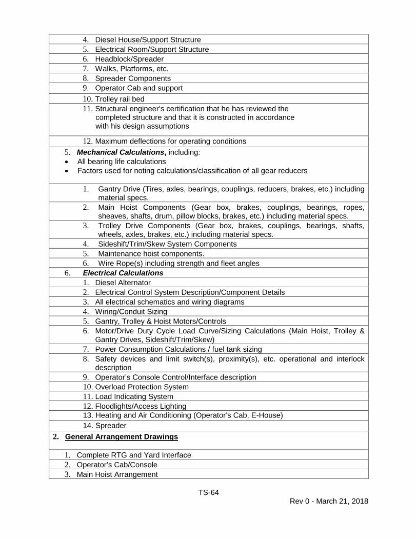
TS-64 Rev 0 - March 21, 2018
4. Diesel House/Support Structure 5. Electrical Room/Support Structure 6. Headblock/Spreader 7. Walks, Platforms, etc. 8. Spreader Components 9. Operator Cab and support 10. Trolley rail bed 11. Structural engineer’s certification that he has reviewed the completed structure and that it is constructed in accordance with his design assumptions
12. Maximum deflections for operating conditions 5. Mechanical Calculations, including: • All bearing life calculations • Factors used for noting calculations/classification of all gear reducers
1. Gantry Drive (Tires, axles, bearings, couplings, reducers, brakes, etc.) including
material specs. 2. Main Hoist Components (Gear box, brakes, couplings, bearings, ropes,
sheaves, shafts, drum, pillow blocks, brakes, etc.) including material specs. 3. Trolley Drive Components (Gear box, brakes, couplings, bearings, shafts,
wheels, axles, brakes, etc.) including material specs. 4. Sideshift/Trim/Skew System Components 5. Maintenance hoist components. 6. Wire Rope(s) including strength and fleet angles
6. Electrical Calculations 1. Diesel Alternator 2. Electrical Control System Description/Component Details 3. All electrical schematics and wiring diagrams 4. Wiring/Conduit Sizing 5. Gantry, Trolley & Hoist Motors/Controls 6. Motor/Drive Duty Cycle Load Curve/Sizing Calculations (Main Hoist, Trolley &
Gantry Drives, Sideshift/Trim/Skew) 7. Power Consumption Calculations / fuel tank sizing 8. Safety devices and limit switch(s), proximity(s), etc. operational and interlock
description 9. Operator’s Console Control/Interface description 10. Overload Protection System 11. Load Indicating System 12. Floodlights/Access Lighting 13. Heating and Air Conditioning (Operator’s Cab, E-House) 14. Spreader
2. General Arrangement Drawings
1. Complete RTG and Yard Interface 2. Operator’s Cab/Console 3. Main Hoist Arrangement
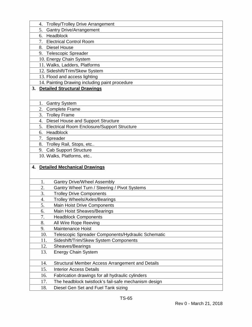
TS-65 Rev 0 - March 21, 2018
4. Trolley/Trolley Drive Arrangement 5. Gantry Drive/Arrangement 6. Headblock 7. Electrical Control Room 8. Diesel House 9. Telescopic Spreader 10. Energy Chain System 11. Walks, Ladders, Platforms 12. Sideshift/Trim/Skew System 13. Flood and access lighting 14. Painting Drawing including paint procedure
3. Detailed Structural Drawings
1. Gantry System 2. Complete Frame 3. Trolley Frame 4. Diesel House and Support Structure 5. Electrical Room Enclosure/Support Structure 6. Headblock 7. Spreader 8. Trolley Rail, Stops, etc.. 9. Cab Support Structure 10. Walks, Platforms, etc..
4. Detailed Mechanical Drawings
1. Gantry Drive/Wheel Assembly 2. Gantry Wheel Turn / Steering / Pivot Systems 3. Trolley Drive Components 4. Trolley Wheels/Axles/Bearings 5. Main Hoist Drive Components 6. Main Hoist Sheaves/Bearings 7. Headblock Components 8. All Wire Rope Reeving 9. Maintenance Hoist 10. Telescopic Spreader Components/Hydraulic Schematic 11. Sideshift/Trim/Skew System Components 12. Sheaves/Bearings 13. Energy Chain System
14. Structural Member Access Arrangement and Details 15. Interior Access Details 16. Fabrication drawings for all hydraulic cylinders 17. The headblock twistlock’s fail-safe mechanism design 18. Diesel Gen Set and Fuel Tank sizing
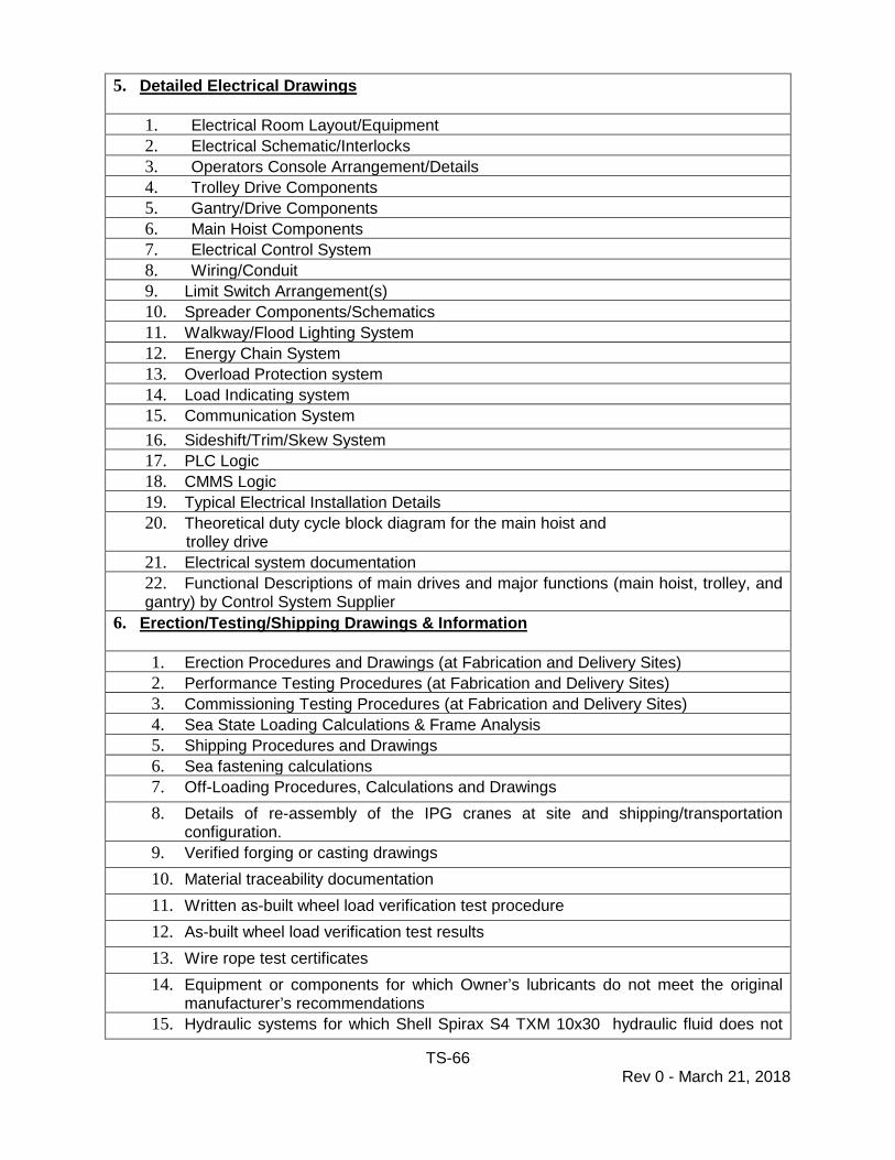
TS-66 Rev 0 - March 21, 2018
5. Detailed Electrical Drawings
1. Electrical Room Layout/Equipment 2. Electrical Schematic/Interlocks 3. Operators Console Arrangement/Details 4. Trolley Drive Components 5. Gantry/Drive Components 6. Main Hoist Components 7. Electrical Control System 8. Wiring/Conduit 9. Limit Switch Arrangement(s) 10. Spreader Components/Schematics 11. Walkway/Flood Lighting System 12. Energy Chain System 13. Overload Protection system 14. Load Indicating system 15. Communication System 16. Sideshift/Trim/Skew System 17. PLC Logic 18. CMMS Logic 19. Typical Electrical Installation Details 20. Theoretical duty cycle block diagram for the main hoist and trolley drive 21. Electrical system documentation 22. Functional Descriptions of main drives and major functions (main hoist, trolley, and gantry) by Control System Supplier
6. Erection/Testing/Shipping Drawings & Information
1. Erection Procedures and Drawings (at Fabrication and Delivery Sites) 2. Performance Testing Procedures (at Fabrication and Delivery Sites) 3. Commissioning Testing Procedures (at Fabrication and Delivery Sites) 4. Sea State Loading Calculations & Frame Analysis 5. Shipping Procedures and Drawings 6. Sea fastening calculations 7. Off-Loading Procedures, Calculations and Drawings 8. Details of re-assembly of the IPG cranes at site and shipping/transportation
configuration. 9. Verified forging or casting drawings 10. Material traceability documentation 11. Written as-built wheel load verification test procedure 12. As-built wheel load verification test results 13. Wire rope test certificates 14. Equipment or components for which Owner’s lubricants do not meet the original
manufacturer’s recommendations 15. Hydraulic systems for which Shell Spirax S4 TXM 10x30 hydraulic fluid does not

TS-67 Rev 0 - March 21, 2018
meet the original manufacturer’s recommendations
7. Operation and Maintenance Manuals
1. Operating Instructions Outline 2. Operating Instructions Final Draft 3. Operating Instructions Final 4. Maintenance and Inspection Manuals - Outline 5. Maintenance and Inspection Manual - Draft 6. Maintenance and Inspection Manual - Final 7. Structural engineer’s certification that he has reviewed the Structural Maintenance
Program and it meets the requirements of the Specifications 8. Maintenance Training Plan
8. As-Built(s)
1. All As-built drawings and calculations of items submitted in the design review.
9. Project Control 1. Project Schedule 2. QA/QC Program and schedule
10. Miscellaneous
1. Control system supplier certification to Owner that the entire cranes’ electrical system design and installation are in conformance to the drive requirements.
2. Detail nameplate requirements and method of marking conductors All information submitted for review, (including drawings and other submittals via email), shall have a cover letter listing all items submitted for review including drawing number & revision. The drawings shall be in the English language and include a description and notation of items revised from revision to revision. Drawings and calculations shall be submitted in a logical order and grouped by assemblies so that the review process can be expedited and all submittal data checked against previous information submitted.