Embed Size (px)
Citation preview

Level Plus®
– 3-IN-1 Measurement – Inherent Accuracy ±1 mm– API Temperature Corrected Volumes– No Scheduled Maintenance or Recalibration– Hazardous Area Certified
Data SheetTank SLAYER®
Magnetostrictive Liquid Level Transmitterswith Temposonics® Technology

I 2 I
Level Plus® Tank Slayer®
Data Sheet
TEMPOSONICS® TECHNOLOGY
Temposonics® Technology is the manner in which MTS applies the principles of magnetostriction to create a reliable position measure-ment system for use in industrial environments. Inside the sensor a torsional strain pulse is induced in a specially designed magnetostric-tive waveguide by the momentary interaction of two magnetic fields. One field comes from a moving magnet, which passes along the outside of the transducer tube, and the other field is generated from a current pulse which is applied to the waveguide. The interaction be-tween these two magnetic fields produces a strain pulse which travels at sonic speed along the sensor waveguide, until the pulse is detected at the head of the transducer. The position of the moving magnet is precisely determined by measuring the elapsed time between the application of the current pulse and the arrival of the strain pulse. As a result, MTS is able to create a reliable position measurement system that is capable of providing an accurate and repeatable measurement.
TANK SLAYER®
The Level Plus® Tank Slayer® liquid level transmitter satisfies the demand for an accurate and robust liquid-level sensor with unsurpassed flexibility to meet most process application conditions. The Tank Slayer® transmitter provides 3-in-1 measurement using one process opening for product level, interface level, and temperature measurements. Once the transmitter is installed and calibrated there is no requirement for scheduled maintenance or recalibration. Set it and forget it!
Features:– 3-in-1 Measurement – Product – Interface – Temperature– No Scheduled Maintenance or Recalibration– Inherent Accuracy ±1mm– Integral Display– Intrinsically Safe– API Temperature Corrected Volumes
Fig. 1: Time-based magnetostrictive position sensing principle
Fig. 2: Example of product and interface level measurement
Standard Rating
FM 3610ISA 60079-11:2014
Class I, Div. 1, Groups A, B, C, D T4Class I, Zone 0/1, AEx ia IIC T4Ta= -50 to 71°C: IP65
C22.2 No. 157C22.2 No. 60079-11:2014
Class I, Div. 1, Groups A, B, C, D T4Class I, Zone 0/1, Ex ia IIC T4Ta= -50 to 71°C: IP65
EN 60079-11:2012 FM14ATEX0068X II 1/2 G Ex ia IIC T4Ta= -50 to 71°C: IP65
IEC 60079-11:2011 IECEx FMG 14.0032XII 1/2 G Ex ia IIC T4 Ga/GbTa= -50 to 71°C: IP65
FM 3615ISA 60079-1
Class I, Div. 1, Groups A, B, C, D T6...T3Class I, Zone 0/1, AEx db IIB+H2 T6...T3 Ga/GbTa= -40 to 71°C: IP65
C22.2 No. 30C22.2 No. 60079-1
Class I, Div. 1, Groups B, C, D T6...T3Ex db IIB+H2 T6...T3 Ga/GbTa= -40 to 71°C: IP65
EN 60079-1:2014 FM16ATEX0068X II 1/2 G Ex db IIB+H2 T6...T3 Ga/GbTa= -40 to 71°C: IP65
IEC 60079-1:2011 IECEx FMG 16.0033XEx db IIB+H2 T6...T3 Ga/GbTa= -40 to 71°C: IP65
Applications:– Inventory Control– Bulk Storage– Custody Transfer
Markets:– Petroleum and Petrochemical– LPG terminals– Food and Beverage
4
5
3
1
Measurement cycle
1 Current pulse generates magnetic field
2 Interaction with position magnet field generates torsional strain pulse
3 Torsional strain pulse propagates
4 Strain pulse detected by converter
5 Time-of-flight converted into distance
Sensing element (Waveguide)
Position magnet (Magnetic field)
Torsional strain pulse converter
2
I 3 I
Level Plus® Tank Slayer®
Data Sheet
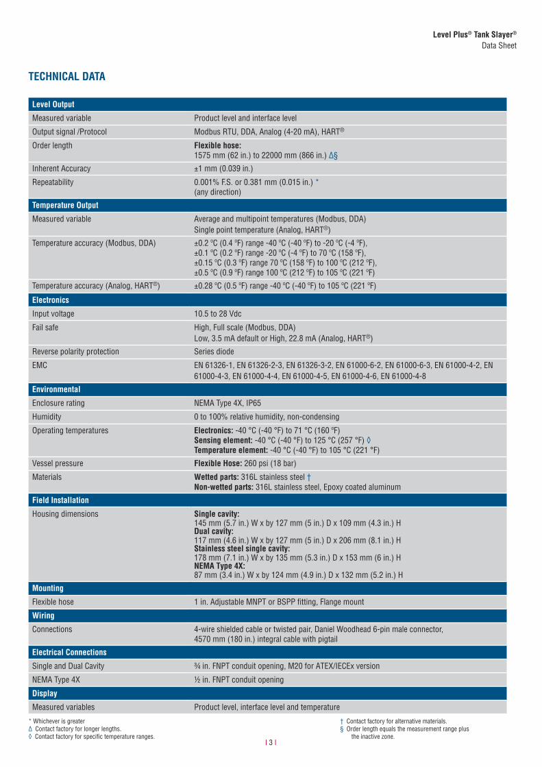
TECHNICAL DATA
Level Output
Measured variable Product level and interface level
Output signal /Protocol Modbus RTU, DDA, Analog (4-20 mA), HART®
Order length Flexible hose: 1575 mm (62 in.) to 22000 mm (866 in.) Ƥ
Inherent Accuracy ±1 mm (0.039 in.)
Repeatability 0.001% F.S. or 0.381 mm (0.015 in.) *(any direction)
Temperature Output
Measured variable Average and multipoint temperatures (Modbus, DDA)Single point temperature (Analog, HART®)
Temperature accuracy (Modbus, DDA) ±0.2 ºC (0.4 ºF) range -40 ºC (-40 ºF) to -20 ºC (-4 ºF),±0.1 ºC (0.2 ºF) range -20 ºC (-4 ºF) to 70 ºC (158 ºF),±0.15 ºC (0.3 ºF) range 70 ºC (158 ºF) to 100 ºC (212 ºF),±0.5 ºC (0.9 ºF) range 100 ºC (212 ºF) to 105 ºC (221 ºF)
Temperature accuracy (Analog, HART®) ±0.28 ºC (0.5 ºF) range -40 ºC (-40 ºF) to 105 ºC (221 ºF)
Electronics
Input voltage 10.5 to 28 Vdc
Fail safe High, Full scale (Modbus, DDA)Low, 3.5 mA default or High, 22.8 mA (Analog, HART®)
Reverse polarity protection Series diode
EMC EN 61326-1, EN 61326-2-3, EN 61326-3-2, EN 61000-6-2, EN 61000-6-3, EN 61000-4-2, EN 61000-4-3, EN 61000-4-4, EN 61000-4-5, EN 61000-4-6, EN 61000-4-8
Environmental
Enclosure rating NEMA Type 4X, IP65
Humidity 0 to 100% relative humidity, non-condensing
Operating temperatures Electronics: -40 °C (-40 °F) to 71 °C (160 ºF)Sensing element: -40 °C (-40 °F) to 125 °C (257 °F) ◊Temperature element: -40 °C (-40 °F) to 105 °C (221 °F)
Vessel pressure Flexible Hose: 260 psi (18 bar)
Materials Wetted parts: 316L stainless steel †Non-wetted parts: 316L stainless steel, Epoxy coated aluminum
Field Installation
Housing dimensions Single cavity:145 mm (5.7 in.) W x by 127 mm (5 in.) D x 109 mm (4.3 in.) H Dual cavity:117 mm (4.6 in.) W x by 127 mm (5 in.) D x 206 mm (8.1 in.) H Stainless steel single cavity:178 mm (7.1 in.) W x by 135 mm (5.3 in.) D x 153 mm (6 in.) H NEMA Type 4X:87 mm (3.4 in.) W x by 124 mm (4.9 in.) D x 132 mm (5.2 in.) H
Mounting
Flexible hose 1 in. Adjustable MNPT or BSPP fitting, Flange mount
Wiring
Connections 4-wire shielded cable or twisted pair, Daniel Woodhead 6-pin male connector,4570 mm (180 in.) integral cable with pigtail
Electrical Connections
Single and Dual Cavity ¾ in. FNPT conduit opening, M20 for ATEX/IECEx version
NEMA Type 4X 1/2 in. FNPT conduit opening
Display
Measured variables Product level, interface level and temperature
* Whichever is greater∆ Contact factory for longer lengths.◊ Contact factory for specific temperature ranges.
† Contact factory for alternative materials.§ Order length equals the measurement range plus the inactive zone.
I 4 I
Level Plus® Tank Slayer®
Data Sheet
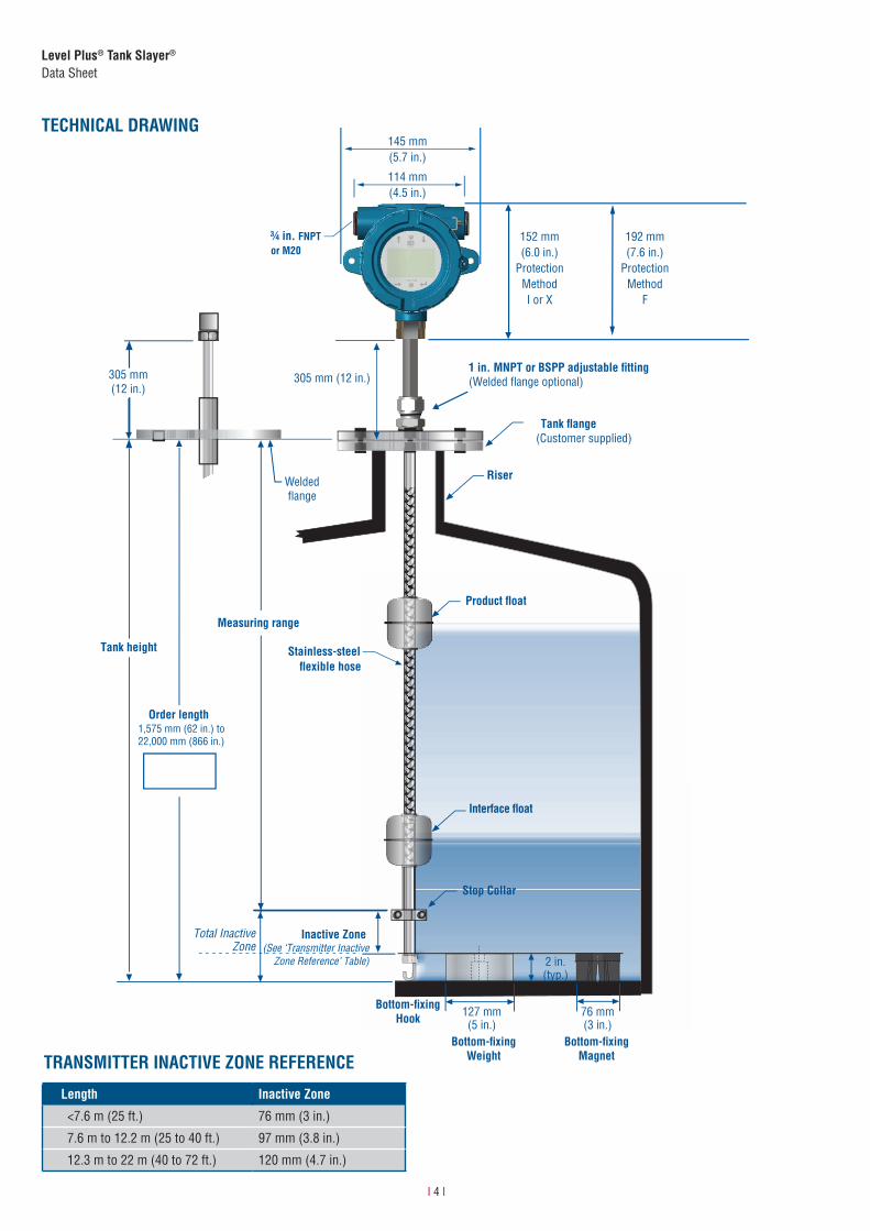
TECHNICAL DRAWING
Length Inactive Zone
<7.6 m (25 ft.) 76 mm (3 in.)
7.6 m to 12.2 m (25 to 40 ft.) 97 mm (3.8 in.)
12.3 m to 22 m (40 to 72 ft.) 120 mm (4.7 in.)
TRANSMITTER INACTIVE ZONE REFERENCE
305 mm(12 in.)
Weldedflange
FNPT
1 in. MNPT or BSPP adjustable �tting
114 mm(4.5 in.)
152 mm(6.0 in.)
Protection MethodI or X
192 mm(7.6 in.)
Protection Method
F
or M20
1,575 mm (62 in.) to 22,000 mm (866 in.)
145 mm(5.7 in.)
Bottom-fixingWeight
Bottom-fixingHook
Bottom-fixingMagnet
I 5 I
Level Plus® Tank Slayer®
Data Sheet
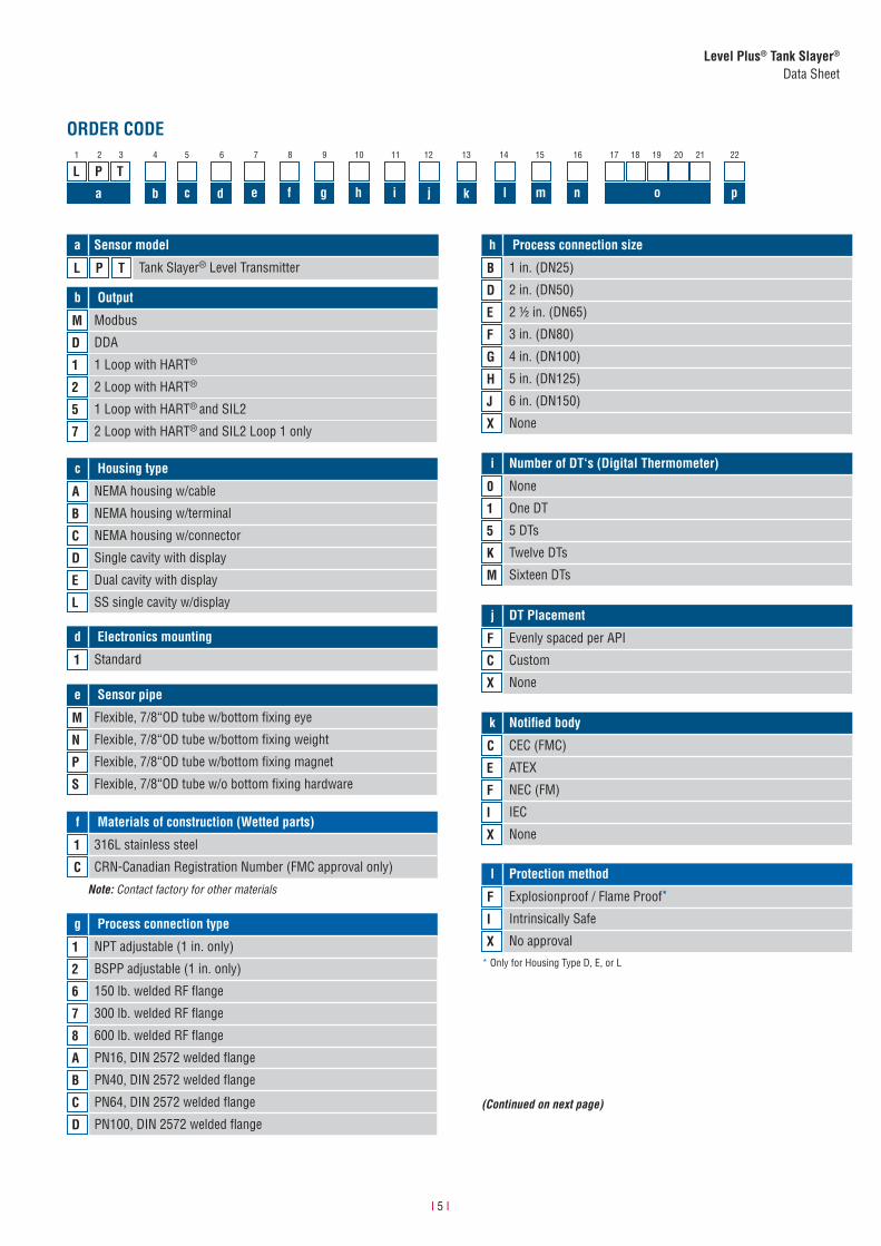
ORDER CODE
b Output
M Modbus
D DDA
1 1 Loop with HART®
2 2 Loop with HART®
5 1 Loop with HART® and SIL2
7 2 Loop with HART® and SIL2 Loop 1 only
j DT Placement
F Evenly spaced per API
C Custom
X None
1 2 3 4 5 6 7 8 9 10 11 12 13 14 15
a Sensor model
L P T Tank Slayer® Level Transmitter
L P T16 17 18 19 20 21 22
a b c d e k
d Electronics mounting
1 Standard
f g h i j l m n o p
c Housing type
A NEMA housing w/cable
B NEMA housing w/terminal
C NEMA housing w/connector
D Single cavity with display
E Dual cavity with display
L SS single cavity w/display
e Sensor pipe
M Flexible, 7/8“OD tube w/bottom fixing eye
N Flexible, 7/8“OD tube w/bottom fixing weight
P Flexible, 7/8“OD tube w/bottom fixing magnet
S Flexible, 7/8“OD tube w/o bottom fixing hardware
h Process connection size
B 1 in. (DN25)
D 2 in. (DN50)
E 2 1/2 in. (DN65)
F 3 in. (DN80)
G 4 in. (DN100)
H 5 in. (DN125)
J 6 in. (DN150)
X None
i Number of DT‘s (Digital Thermometer)
0 None
1 One DT
5 5 DTs
K Twelve DTs
M Sixteen DTs
k Notified body
C CEC (FMC)
E ATEX
F NEC (FM)
I IEC
X Nonef Materials of construction (Wetted parts)
1 316L stainless steel
C CRN-Canadian Registration Number (FMC approval only)
g Process connection type
1 NPT adjustable (1 in. only)
2 BSPP adjustable (1 in. only)
6 150 lb. welded RF flange
7 300 lb. welded RF flange
8 600 lb. welded RF flange
A PN16, DIN 2572 welded flange
B PN40, DIN 2572 welded flange
C PN64, DIN 2572 welded flange
D PN100, DIN 2572 welded flange
Note: Contact factory for other materials
(Continued on next page)
* Only for Housing Type D, E, or L
l Protection method
F Explosionproof / Flame Proof*
I Intrinsically Safe
X No approval
I 6 I
Level Plus® Tank Slayer®
Data Sheet
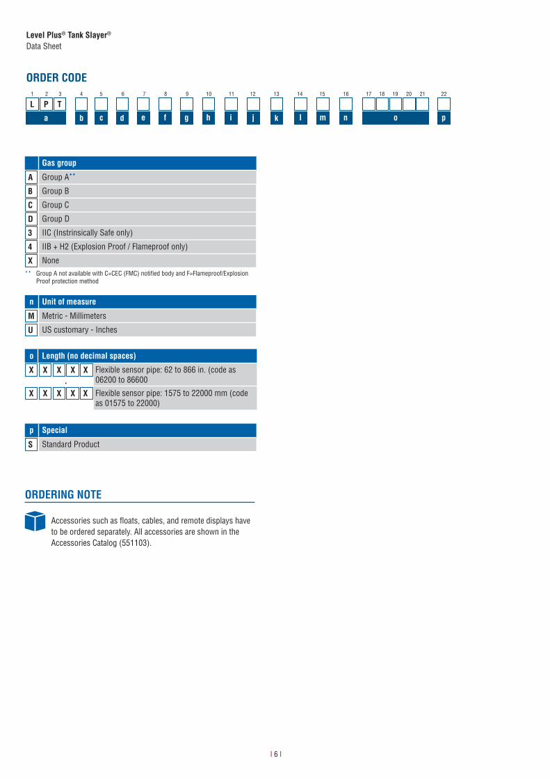
ORDER CODE1 2 3 4 5 6 7 8 9 10 11
L P T
a b c d e f g h i
12 13 14 15 16 17 18 19 20 21 22
kj l m n o p
n Unit of measure
M Metric - Millimeters
U US customary - Inches
ORDERING NOTE
Accessories such as floats, cables, and remote displays have to be ordered separately. All accessories are shown in the Accessories Catalog (551103).
Gas group
A Group A**
B Group B
C Group C
D Group D
3 IIC (Instrinsically Safe only)
4 IIB + H2 (Explosion Proof / Flameproof only)
X None
p Special
S Standard Product
o Length (no decimal spaces)
X X X X X Flexible sensor pipe: 62 to 866 in. (code as 06200 to 86600
X X X X X Flexible sensor pipe: 1575 to 22000 mm (code as 01575 to 22000)
** Group A not available with C=CEC (FMC) notified body and F=Flameproof/Explosion Proof protection method
.
I 7 I
Level Plus® Tank Slayer®
Data Sheet
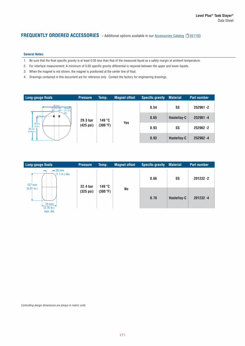
FREQUENTLY ORDERED ACCESSORIES – Additional options available in our Accessories Catalog 551103
Controlling design dimensions are always in metric units
Long-gauge floats Pressure Temp. Magnet offset Specific gravity Material Part number
L
92 mm(3.6 in.) dia.
76 mm(3 in.)
88 mm(3.44 in.)
C Magnet
28 mm(1.1 in.)dia.
29.3 bar(425 psi)
149 °C (300 ºF)
Yes
0.54 SS 252961 -2
0.65 Hastelloy-C 252961 -4
0.93 SS 252962 -2
0.93 Hastelloy-C 252962 -4
Long-gauge floats Pressure Temp. Magnet offset Specific gravity Material Part number
22.4 bar(325 psi)
149 °C (300 ºF)
No
0.66 SS 201232 -2
0.70 Hastelloy-C 201232 -4
General Notes:
1. Be sure that the float specific gravity is at least 0.05 less than that of the measured liquid as a safety margin at ambient temperature.
2. For interface measurement: A minimum of 0.05 specific gravity differential is required between the upper and lower liquids.
3. When the magnet is not shown, the magnet is positioned at the center line of float.
4. Drawings contained in this document are for reference only. Contact the factory for engineering drawings.
28 mm(1.1 in.) dia.
127 mm(5.01 in.)
70 mm(2.76 in.) max. dia.
Document Part Number: 551688 Revision C (EN) 03/2018
LOCA
TION
S
LEGA
L NO
TICE
SUSA MTS Systems CorporationSensors Division3001 Sheldon DriveCary, N.C. 27513, USATel. +1 919 677-0100Fax +1 919 [email protected]
JAPANMTS Sensors Technology Corp.737 Aihara-machi, Machida-shi, Tokyo 194-0211, JapanTel. + 81 42 775-3838Fax + 81 42 775- [email protected]
FRANCEMTS Systems SASZone EUROPARC Bâtiment EXA 1616/18, rue Eugène Dupuis94046 Creteil, FranceTel. + 33 1 58 4390-28Fax + 33 1 58 [email protected]
GERMANYMTS Sensor TechnologieGmbH & Co. KGAuf dem Schüffel 958513 Lüdenscheid, GermanyTel. + 49 2351 9587-0Fax + 49 2351 [email protected]
CHINAMTS Sensors Room 504, Huajing Commercial Center, No. 188, North Qinzhou Road200233 Shanghai, ChinaTel. +86 21 6485 5800 Fax +86 21 6495 [email protected]
ITALYMTS Systems Srl.Sensor DivisionVia Camillo Golgi, 5/725064 Gussago (BS), ItalyTel. + 39 030 988 3819Fax + 39 030 982 [email protected]
MTS, Temposonics and Level Plus are registered trademarks of MTS Systems Corporationin the United States; MTS SENSORS and the MTS SENSORS logo are trademarks of MTSSystems Corporation within the United States. These trademarks may be protected in othercountries. All other trademarks are the property of their respective owners.Copyright © 2018 MTS Systems Corporation. No license of any intellectual propertyrights is granted. MTS reserves the right to change the information within this document,change product designs, or withdraw products from availability for purchase withoutnotice. Typographic and graphics errors or omissions are unintentional and subject tocorrection. Visit www.mtssensors.com for the latest product information.
S a f e t y I n t e g r i t y L e v e lIEC 61508


![Gauge fixing and BRST formalism arXiv:0712.0876v1 [hep-th] 6 … · 2013-02-15 · arXiv:0712.0876v1 [hep-th] 6 Dec 2007 Gauge fixing and BRST formalism in non-Abelian gauge theories](https://img.pdfslide.us/doc/110x75/5f0483727e708231d40e57e5/gauge-ixing-and-brst-formalism-arxiv07120876v1-hep-th-6-2013-02-15-arxiv07120876v1.jpg)


![RT4-002 1700 RT4-009 C] RT4-016 D RT4-013 C] RT4-027 RT4](https://img.pdfslide.us/doc/110x75/6190ee7d3a956e77f659bddc/rt4-002-1700-rt4-009-c-rt4-016-d-rt4-013-c-rt4-027-rt4-.jpg)