Embed Size (px)
Citation preview
Packaged Rooftops
July 2006 RT-PRC023-EN
13 SEER R-22, R-410A Precedent™
3-5 Tons — 60 Hz
Packaged Cooling, Heat Pumps (T*C), (WSC)
Packaged Gas/Electric (Y*C)

Introduction
© 2006 American Standard Inc. All rights reserved RT-PRC023-EN
Packaged Rooftop Air Conditioners Through the years, Trane has designed and developed the most complete line of Packaged Rooftop products available in the market today. Trane was the first to introduce the Micro—microelectronic unit controls—and has continued to improve and revolutionize this design concept.
Electromechanical controls are available for simpler applications, and for the more sophisticated, ReliaTel™ microprocessor controls.
The ReliaTel control platform offers the same great features and functionality as the original Micro, with additional benefits for greater application flexibility.
With its sleek, compact cabinet, rounded corners and beveled top Precedent continues to provide the highest standards in quality and reliability, comfort, ease of service, and the performance of Trane light commercial products.
Trane customers demand products that provide exceptional reliability, meet stringent performance requirements, and are competitively priced. Trane delivers with Precedent.
Precedent features cutting edge technologies: reliable compressors, Trane engineered ReliaTel controls, computer-aided run testing, and Integrated Comfort™ Systems. So, whether you’re the contractor, the engineer, or the owner you can be certain Precedent Products are built to meet your needs.
It’s Hard To Stop A Trane.®
Packaged Cooling and Heat Pumps
Packaged Gas/Electric

RT-PRC023-EN 3
Features and Benefits . . . . . . . . . . . . . . . . . . . . . . . . . . 4Application Considerations . . . . . . . . . . . . . . . . . . . . 11
Selection Procedure . . . . . . . . . . . . . . . . . . . . . . . . . . 12
Model Number Description . . . . . . . . . . . . . . . . . . . . 14
General Data . . . . . . . . . . . . . . . . . . . . . . . . . . . . . . . . 16
Performance Data . . . . . . . . . . . . . . . . . . . . . . . . . . . . 24
Controls . . . . . . . . . . . . . . . . . . . . . . . . . . . . . . . . . . . . 70
Electrical Data . . . . . . . . . . . . . . . . . . . . . . . . . . . . . . . 72
Jobsite Connections . . . . . . . . . . . . . . . . . . . . . . . . . . 78
Dimensional Data . . . . . . . . . . . . . . . . . . . . . . . . . . . . 79
Weights . . . . . . . . . . . . . . . . . . . . . . . . . . . . . . . . . . . . 90
Mechanical Specifications . . . . . . . . . . . . . . . . . . . . . 92
Contents

4 RT-PRC023-EN
Standard Features
• 1” throwaway filters provided on 3-5 ton Cooling/Gas and 3-4 ton Heat Pump units
• 2” throwaway filters provided on 5 ton Heat Pump units
• 5-year Limited Compressor Warranty
• 5-year Limited Heat Exchanger Warranty
• 1-year Limited Parts Warranty
• Anti-Short Cycle Timer (Standard with ReliaTel™)
• Belt Drive Motors (Three-phase)
• Colored and Numbered Wiring
• Convertible Airflow
• Easy Access Low Voltage Terminal Board (LTB)
• Electromechanical or ReliaTel Microprocessor Controls1
• Foil-Faced and Edge Captured Insulation
• High Pressure Control
• IAQ Dual Sloped and Removable Drain Pans
• Liquid Line Refrigerant Drier
• Low Ambient Cooling to 0°F on Microprocessor Models
• Low Ambient Cooling to 40°F on Electromechanical Models
• Multispeed Direct Drive Motors (Single-phase)2
• Operating Charge of R-223
• Operating Charge of R-410A4
• Patented Hybrid Condenser Coil for easy cleaning
• Progressive Tubular Aluminized Steel Heat Exchanger
• Provisions for Through-the-Base Gas and Condensate Drain Connections
• Quick Access Panels
1 Not av ailab le for 3 -5 Tons, R-410A Heat Pumps2 Standard for 3 -5 Tons, R-410A units3 Av ailable for 3 -5 Tons, R-22 un its on ly4 Standard for 3 -5 Tons, R-410A units
• Quick Adjust Fan Motor Mounting Plate
• Single Point Power
• Single Side Service
• Standardized Components
• Thermal Expansion Valve
• Trane built Scroll Compressors
Options*
Factory Installed Options
• Black Epoxy Pre-Coated Coils
• CompleteCoat™ Condenser Coil
• Dehumidification Option5
• Hinged Access Doors
• Novar Return Air Sensor
• Novar Unit Controls
• Phase Monitor
• Powered or Unpowered Convenience Outlet
• Stainless Steel Heat Exchanger with 10-year warranty
• Supply and/or Return Air Smoke Detector
• Through the Base Electrical Access
• Through the Base Electrical with Circuit Breaker
• Through the Base Electrical with Disconnect Switch
• 2” Pleated Filters
Factory or Field Installed Options
• Barometric Relief
• Clogged Filter/Fan Failure Switch
• Crankcase Heaters
• Discharge Air Sensing Kit
• Economizer
• Electric Heaters
• Frostat
• LonTalk® Communications Interface (LCI)
• Reference or Comparative Enthalpy
5 Avai la ble for 3-5 Tons , R-22 un its only
• Tool-less Hail Guards
• Trane Communications Interface (TCI)
Field Installed Options
• CO2 Sensing
• Digital Display Zone Sensor
• Dual Thermistor Remote Zone Sensor
• High Altitude Kit
• High Static Drive
• Humidity Sensor
• LP Conversion Kit
• Manual Outside Air Damper
• Motorized Outside Air Dampers
• Powered Exhaust
• Quick Adapt Curbs
• Quick Start Kit
• Remote Potentiometer
• Roof Curb
• Thermostat
• Ventilation Override Accessory
• Zone Sensor
*Refer to Model Number Description for option availability.
Other Benefits
• Cabinet design ensures water integrity
• Ease of Service, Installation and Maintenance
• Mixed model build enables “fastest in the industry” ship cycle times
• Outstanding Airflow Distribution
• ReliaTel Controls
• Unmatched Product Support is one of our finest assets. Trane Sales Representatives are a Support Group that can assist you with:
Features and Benefits

RT-PRC023-EN 5
Features and Benefits
– Product
– Application
– Service
– Training
– Special Applications
– Specifications
– Computer Programs and much more
Standard Features
Anti-Short Cycle Timer (Standard with ReliaTel)
Provides a 3 minute minimum “ON” time and 3 minute “OFF” time for compressors to enhance compressor reliability by assuring proper oil return.
Belt Drive Motors (Three-phase)
For additional static requirements, Precedent 3-5 ton units offer an optional belt drive motor to meet a wide range of airflow needs.
Direct Drive Motors (Single-phase R-410A)
For additional static requirements, single-phase R-410A units offer multi-speed, direct drive motors.
Colored And Numbered Wiring
Save time and money tracing wires and diagnosing the unit.
Compressors
Precedent contains the best compressor technology available to achieve the highest possible performance. Our compressor line includes Trane built scrolls.
Condenser Coil
Precedent boasts a patent-pending 1+1+1 condenser coil, permanently gapped for easy cleaning.
Controls – ReliaTel or Electromechanical
ReliaTel microprocessor controls provide unit control for heating, cooling and ventilating utilizing input from sensors that measure indoor and outdoor temperature and other zone sensors. ReliaTel also provides outputs for building automation systems and expanded diagnostics. For a complete list of ReliaTel offerings, refer to the “Other Benefits” section within the Features and Benefits section of this catalog.
For the simpler job that does not require a building automation system, or expanded diagnostics capabilities, Precedent offers electromechanical controls. This 24-volt control includes the control transformer and contactor pressure lugs for power wiring.
Convertible Units
The units ship in a downflow configuration. They can be easily converted to horizontal by simply moving two panels.
Units come complete with horizontal duct flanges so the contractor doesn’t have to field fabricate them. These duct flanges are a time and cost saver.
Cooling
Standard or High Efficiency Cooling available.
Dual Sloped Drain Pans
Every Precedent unit has a non-corrosive, removable, double-sloped drain pan that’s easy to clean and reversible to allow installation of drain trap on either side of the unit.
Easy Access Low Voltage Terminal Board
Precedent’s Low Voltage Terminal Board is external to the electrical control cabinet. It is extremely easy to locate and attach the thermostat wire and test operation of all unit functions. This is another cost and time saving installation feature.
Foil Faced Insulation
All panels in the evaporator section of the unit have cleanable foil-faced insulation. All edges are either captured or sealed to ensure no insulation fibers get into the airstream.
Heat Exchanger
The compact cabinet features a progressive tubular heat exchanger in low, medium and high heat capacities.
The heat exchanger is fabricated using stainless steel burners and corrosion-resistant aluminized steel tubes as standard on all models. It has an induced draft blower to pull the gas mixture through the burner
6 RT-PRC023-EN
Features and Benefits
tubes. The heater has a direct spark ignition system which doubles as a safety device to prove the flame.
Gas/Electric Precedent models exceed all California seasonal efficiency requirements. They also perform better than required to meet the California NOx emission requirements.
High Pressure Control
All units include High Pressure Control as standard.
Low Ambient Cooling
All Precedent microprocessor units have cooling capabilities down to 0°F as standard. Electromechanical models have cooling capabilities to 40°F as built, or to 0°F by adding the optional low ambient control (frostat).
Low Voltage Connections
The wiring of the low voltage connections to the unit and the zone sensors is as simple as 1-1, 2-2, and 3-3. This simplified system makes it easy for the installer to wire.
Motors
Belt drive (three-phase) or multispeed direct drive6 (single-phase) motors are available.
Quick-Access Panels
Remove two screws for access to the standardized internal components and wiring.
Quick-Adjust Idler Arm
With the Quick-Adjust Idler Arm, the belt and sheaves can be quickly adjusted without moving the mounted fan motor. The result is a major savings in time and money.
6 Not av ailab le f or 3 -5 Tons, R-410A Heat Pumps
Single Point Power
A single electrical connection powers the unit.
Single Side Service
Single side service is standard on all units.
Standardized Components
Components are placed in the same location on all Precedent units. Familiarize yourself with one Precedent and you are familiar with every Precedent.
Due to standardized components throughout the Precedent line, contractors/owners can stock fewer parts.
Thermal Expansion Valve
Available for a wider range of applications. This feature is standard on all R-410A units.
Through the Base Condensate
Every unit includes provisions for through the base condensate drain connections. This allows the drain to be connected through the roof curb instead of a roof penetration.
Variety of Options*
Factory Installed Options
Black Epoxy Pre-Coated Coils
The pre-coated coils are an economical option for protection in mildly corrosive environments.
CompleteCoat™ Condenser Coil
These coils provide excellent corrosion resistance as well as uniformity of coverage and coating thickness.
Disconnect Switch (Required with Through-the-Base Electrical)
Factory installed 3-pole, molded case, disconnect switch with provisions for through the base electrical connections are available.
Codes require a method of assured unit shutdown for servicing. Field-installed disconnects sometimes interfere with service access. Factory installation of unit disconnects
reduces costs, assures proper mounting and provides the opportunity to upgrade to unit circuit breaker protection.
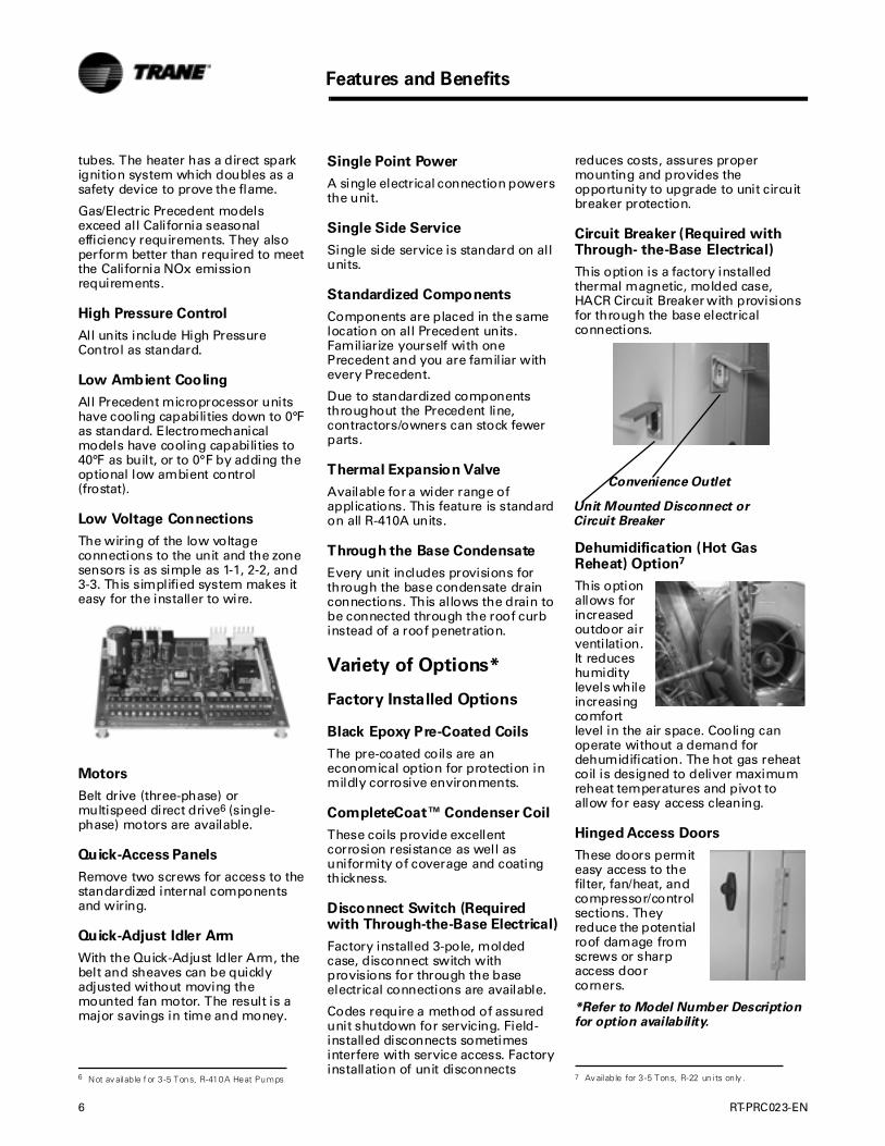
Circuit Breaker (Required with Through- the-Base Electrical)
This option is a factory installed thermal magnetic, molded case, HACR Circuit Breaker with provisions for through the base electrical connections.
Dehumidification (Hot Gas Reheat) Option7
This option allows for increased outdoor air ventilation. It reduces humidity levels while increasing comfort level in the air space. Cooling can operate without a demand for dehumidification. The hot gas reheat coil is designed to deliver maximum reheat temperatures and pivot to allow for easy access cleaning.
Hinged Access Doors
These doors permit easy access to the filter, fan/heat, and compressor/control sections. They reduce the potential roof damage from screws or sharp access door corners.
*Refer to Model Number Description for option availability.
7 Av ailab le for 3 -5 Tons, R-22 un i ts on ly .
Unit Mounted Disconnect or Circuit Breaker
Convenience Outlet

RT-PRC023-EN 7
Features and Benefits
Novar Unit Controls
Novar 3051 and 2024 are available for Precedent Gas and Electric Heat models.
Phase Monitor
Phase monitor shall provide 100% protection for motors and compressors against problems caused by phase loss, phase imbalance, and phase reversal. Phase monitor is equipped with an LED that provides an ON or FAULT indicator.
Powered or Unpowered Convenience Outlet
This option is a GFCI, 120v/15amp, 2 plug, convenience outlet, either powered or unpowered. This option can only be ordered when Through the Base Electrical with either the Disconnect Switch or Circuit Breaker option is ordered.
Stainless Steel Heat Exchanger
The optional stainless steel heat exchanger is constructed of 304 stainless steel. It is resistant to corrosion and oxidation and easy to clean.
The high strength to weight ratio allows for high ventilation rates with gas units. It is an excellent option to compliment the dehumidification option as a high outside air ventilation unit.
With this option, a 10-year stainless steel heat exchanger warranty is standard.
Supply and/or Return Air Smoke Detector
With this option installed, if smoke is detected, all unit operation will be shut down. Reset will be manual at the unit. Return Air Smoke Detectors require minimum allowable airflow when used with certain models.
Through-the-Base Electrical Utility Access
An electrical service entrance shall be provided allowing electrical access for both control and main power connections inside the curb and through the base of the unit. Option will allow for field installation of liquid-tight conduit and an external field installed disconnect switch.
Factory provided through the base openings simplify wiring and piping. Because these utility openings frequently minimize the number of roof penetrations, the integrity of roofing materials is enhanced.
Two-Inch Pleated Filters
2” pleated media filters are offered as an option on all Precedent units for jobs with enhanced Indoor Air Quality (IAQ) requirements.
Factory or Field Installed Options*
Barometric Relief
Designed to be used on downflow units, barometric relief is an unpowered means of relieving excess building pressure.
Clogged Filter/Fan Failure Switch
A dedicated differential pressure switch is available to achieve active fan failure indication and/or clogged filter indication.
These sensors allow a zone sensor service light or Integrated Comfort System to indicate a dirty filter or a fan that’s not working. The field installation charges for these valuable feedback devices often eliminate them from consideration. Factory installation can make such features a good investment.
Crankcase Heaters
These band or insertion heaters provide improved compressor reliability by warming the oil to prevent migration during off-cycles or low ambient conditions.
Discharge Air Sensing Kit
Provides true discharge air sensing in heating models. The kit is functional only with the ReliaTel Options Module.
Electric Heaters
Electric heat modules are available within the basic unit. If ordering the Through the Base Electrical option with an Electrical Heater, the heater must be factory installed.
Fresh Air Options – Dampers and Economizer
0 - 25% manual or 0 - 50% motorized outside air hoods are available.
Economizers are equipped with either dry bulb or reference or comparative enthalpy sensing. These economizers provide free cooling as the outdoor temperature and/or humidity decreases. Correctly installed, they offer a valuable energy savings. Factory-installed economizers save time and ensure proper installation.
The economizers come with three control options — dry bulb is standard, enthalpy and differential enthalpy are optional.
*Refer to Model Number Description for option availability.
8 RT-PRC023-EN
Features and Benefits
Frostat
This capillary bulb embedded in the face of the evaporator coil monitors coil temperature to prevent evaporator icing and protect the compressor. Recommended for applications with low leaving air temperatures, low airflow and or high latent load applications.
LonTalk® Communications Interface
The LonTalk communications interface allows the unit to communicate as a Tracer™LCI-V device or directly with generic LonTalkNetwork Building Automation System Controls.
Reference or Comparative Enthalpy
Measures and communicates humidity while maximizing comfort control.
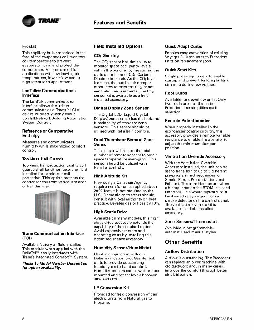
Tool-less Hail Guards
Tool-less, hail protection quality coil guards shall be either factory or field-installed for condenser coil protection. This option protects the condenser coil from vandalism and/or hail damage.
Trane Communication Interface (TCI)
Available factory or field installed. This module when applied with the ReliaTel™ easily interfaces with Trane’s Integrated Comfort™ System.
*Refer to Model Number Description for option availability.
Field Installed Options
CO2 Sensing
The CO2 sensor has the ability to monitor space occupancy levels within the building by measuring the parts per million of CO2 (Carbon Dioxide) in the air. As the CO2 levels increase, the outside air damper modulates to meet the CO2 space ventilation requirements. The CO2 sensor kit is available as a field installed accessory.
Digital Display Zone Sensor
The Digital LCD (Liquid Crystal Display) zone sensor has the look and functionality of standard zone sensors. This sensor should be utilized with ReliaTel™ controls.
Dual Thermistor Remote Zone Sensor
This sensor will reduce the total number of remote sensors to obtain space temperature averaging. This sensor should be utilized with ReliaTel controls.
High Altitude Kit
Previously a Canadian Agency requirement for units applied about 2000 feet, it is not required by the U.S. Domestic contractors should consult with local authority on best practice. Devates gas orifices by 10%.
High Static Drive
Available on many models, this high static drive accessory extends the capability of the standard motor. Avoid expensive motors and operating costs by installing this optimized sheave accessory.
Humidity Sensor/Humidistat
Used in conjunction with our Dehumidification (Hot Gas Reheat) units to provide outstanding humidity control and comfort. Humidity sensors can be wall or duct mounted and set for levels between 40% and 60%.
LP Conversion Kit
Provided for field conversion of gas/electric units from Natural gas to Propane.
Quick Adapt Curbs
Enables easy conversion of existing Voyager 3-10 ton units to Precedent units on replacement jobs.
Quick Start Kits
Single phase equipment to enable startup and prevent building lighting dimming during low voltage.
Roof Curbs
Available for downflow units. Only two roof curbs for the entire Precedent line simplifies curb selection.
Remote Potentiometer
When properly installed in the economizer control circuitry, this accessory provides a remote variable resistance to enable the operator to adjust the minimum damper position.
Ventilation Override Accessory
With the Ventilation Override Accessory installed, the unit can be set to transition to up to 3 different pre-programmed sequences for Smoke Purge, Pressurization, and Exhaust. The transition occurs when a binary input on the RTOM is closed (shorted). This would typically be a hard wired relay output from a smoke detector or fire control panel. The ventilation override kit is available as a field installed accessory.
Zone Sensors/Thermostats
Available in programmable, automatic and manual styles.
Other Benefits
Airflow Distribution
Airflow is outstanding. The Precedent can replace an older machine with old ductwork and, in many cases, improve the comfort through better air distribution.
RT-PRC023-EN 9
Features and Benefits
Cabinet Integrity
For added water integrity, Precedent has a raised 1 1/8" lip around the supply and return of the downflow units to prevent water from blowing into the ductwork.
Easy to Install, Service and Maintain
Because today’s owners are very cost-conscious when it comes to service and maintenance, the Trane Precedent was designed with direct input from service contractors. This valuable information helped to design a product that would get the serviceman off the job quicker and save the owner money. Precedent does this by offering outstanding standard features enhanced by a variety of factory and field installed options, multiple control options, rigorously tested proven designs and superior product and technical support.
Flexibility
Precedent offers ultimate flexibility. Units are built to order in our standard “shortest in the industry” ship cycle time.
Unit Cabinet
The compact cabinet with rounded corners takes up less room and is less costly to ship. The beveled and ribbed top is not only aesthetically pleasing, it is designed to prevent water from pooling.
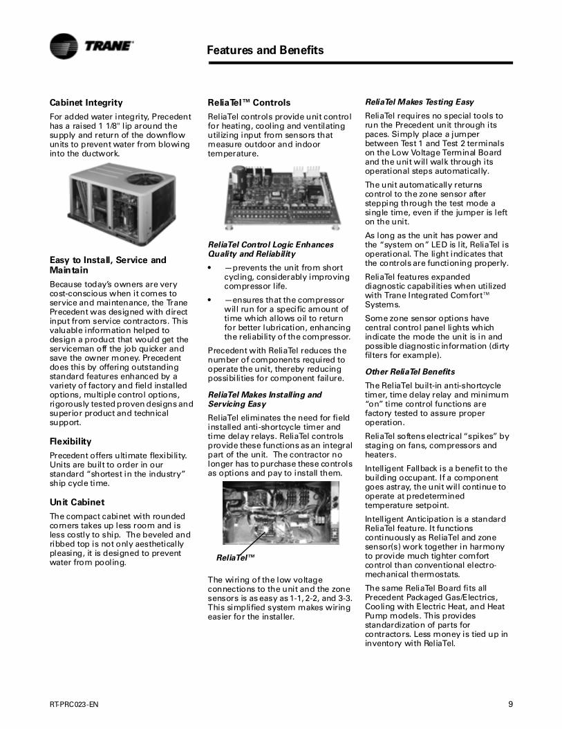
ReliaTel™ Controls
ReliaTel controls provide unit control for heating, cooling and ventilating utilizing input from sensors that measure outdoor and indoor temperature.
ReliaTel Control Logic Enhances Quality and Reliability
• —prevents the unit from short cycling, considerably improving compressor life.
• —ensures that the compressor will run for a specific amount of time which allows oil to return for better lubrication, enhancing the reliability of the compressor.
Precedent with ReliaTel reduces the number of components required to operate the unit, thereby reducing possibilities for component failure.
ReliaTel Makes Installing and Servicing Easy
ReliaTel eliminates the need for field installed anti-shortcycle timer and time delay relays. ReliaTel controls provide these functions as an integral part of the unit. The contractor no longer has to purchase these controls as options and pay to install them.
The wiring of the low voltage connections to the unit and the zone sensors is as easy as 1-1, 2-2, and 3-3. This simplified system makes wiring easier for the installer.
ReliaTel Makes Testing Easy
ReliaTel requires no special tools to run the Precedent unit through its paces. Simply place a jumper between Test 1 and Test 2 terminals on the Low Voltage Terminal Board and the unit will walk through its operational steps automatically.
The unit automatically returns control to the zone sensor after stepping through the test mode a single time, even if the jumper is left on the unit.
As long as the unit has power and the “system on” LED is lit, ReliaTel is operational. The light indicates that the controls are functioning properly.
ReliaTel features expanded diagnostic capabilities when utilized with Trane Integrated Comfort™ Systems.
Some zone sensor options have central control panel lights which indicate the mode the unit is in and possible diagnostic information (dirty filters for example).
Other ReliaTel Benefits
The ReliaTel built-in anti-shortcycle timer, time delay relay and minimum “on” time control functions are factory tested to assure proper operation.
ReliaTel softens electrical “spikes” by staging on fans, compressors and heaters.
Intelligent Fallback is a benefit to the building occupant. If a component goes astray, the unit will continue to operate at predetermined temperature setpoint.
Intelligent Anticipation is a standard ReliaTel feature. It functions continuously as ReliaTel and zone sensor(s) work together in harmony to provide much tighter comfort control than conventional electro-mechanical thermostats.
The same ReliaTel Board fits all Precedent Packaged Gas/Electrics, Cooling with Electric Heat, and Heat Pump models. This provides standardization of parts for contractors. Less money is tied up in inventory with ReliaTel.
ReliaTel™
10 RT-PRC023-EN
Features and Benefits
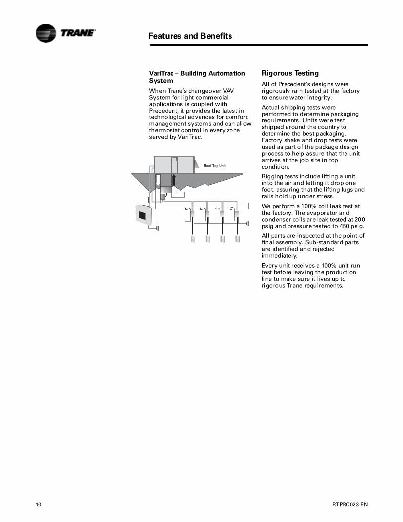
VariTrac – Building Automation System
When Trane’s changeover VAV System for light commercial applications is coupled with Precedent, it provides the latest in technological advances for comfort management systems and can allow thermostat control in every zone served by VariTrac.
Rigorous Testing
All of Precedent’s designs were rigorously rain tested at the factory to ensure water integrity.
Actual shipping tests were performed to determine packaging requirements. Units were test shipped around the country to determine the best packaging. Factory shake and drop tests were used as part of the package design process to help assure that the unit arrives at the job site in top condition.
Rigging tests include lifting a unit into the air and letting it drop one foot, assuring that the lifting lugs and rails hold up under stress.
We perform a 100% coil leak test at the factory. The evaporator and condenser coils are leak tested at 200 psig and pressure tested to 450 psig.
All parts are inspected at the point of final assembly. Sub-standard parts are identified and rejected immediately.
Every unit receives a 100% unit run test before leaving the production line to make sure it lives up to rigorous Trane requirements.
RT-PRC023-EN 11
Heating Operation
The heat exchanger is manufactured with aluminized steel. To prevent condensation within the heat exchanger, do not exceed 50% outside air or a minimum mixed air temperature of 40°F.
Low Ambient Cooling
The Precedent™ line features, with ReliaTel™ microprocessor controls, low ambient cooling down to 0°F. With electromechanical controls, Precedent features low ambient cooling to 40°F. The following options need to be included/considered when low ambient applications are required: continuous fan operation, crankcase heaters, thermal expansion valves, frostat.
Contact your local Trane Representative for more assistance with low ambient cooling applications.
Optional Stainless Steel Heat Exchanger
The optional stainless steel heat exchanger is manufactured with 304 stainless steel. To prevent corrosion and prolong heat exchanger reliability, the minimum mixed air temperature allowed across the heat exchanger is 20°F.
The stainless steel heat exchanger option is an excellent option that compliments the dehumidification package. Whenever high outside air or outside applications exist, these options should be utilized.
Unit Pitch
These units have reversible sloped condensate drain pans. Units must be installed level. Any unit slope must be toward the side of unit where condensate drain is connected.
Application of this product should be within the cataloged airflow and cooling considerations.
Barometric Relief
This product line offers an optional barometric relief damper for use in conjunction with economizer option. This accessory consists of gravity dampers which open with increased pressure. As the building air pressure increases, the pressure in the unit return air section also increases, opening the dampers and relieving the conditioned space.
Note: The effectiveness of barometric relief damper during economizing operation is system related.
Note: Pressure drop of the return air system should be considered to control building pressurization.
Black Epoxy Coil
The coils are manufactured with a thermoset, vinyl coating that is bonded to the aluminum fin stock prior to the fin stamping process. These coils are an economical option for protection in mildly corrosive environments.
Note: Not to be used where seacoast applications exist.
CompleteCoat™ Condenser Coil
The coils provide protection from corrosive environments and is ideal for seacoast applications.
Condensate Trap
The evaporator is a draw-thru configuration. A trap must be field provided prior to start-up on the cooling cycle.
Clearance Requirements
The recommended clearances identified with unit dimensions should be maintained to assure adequate service maximum capacity and peak operating efficiency. Actual clearances which appear inadequate should be reviewed with the local Trane sales personnel.
Application Considerations

12 RT-PRC023-EN
Cooling Capacity
Note: Cooling Capacity Procedure is the same for electric heat (T*C) and gas heat (Y*C).
Step 1.
Calculate the building’s total and sensible cooling loads at design conditions. Use the Trane calculation methods or any other standard accepted method.
Factors used in unit selection:
Packaged Cooling with Optional Electric HeatTotal Cooling Load: 59 MBh Sensible Cooling Load: 40 MBh Airflow: 2000 cfm Electrical Characteristics: 460/60/3Summer Design Conditions: Entering Evaporator Coil: 80 DB, 67 WB Outdoor Ambient: 95 External Static Pressure: 0.36 in. wgDownflow ConfigurationEfficiency: 13 SEEREconomizer
Step 2.
As a starting point, a rough determination must be made of the size of the unit. The final selection will be made after examining the performance at the given conditions. Divide the total cooling load by nominal BTUH per ton (12 MBh per ton); then round up to the nearest unit size.
59 MBh / 12 MBh = approx. 5 tons
Step 3.
Table 8 shows that a THC063A4 has a gross cooling capacity of 62.4 MBh and 47.3 MBh sensible capacity at 2000 cfm and 95 DB outdoor ambient with 80 DB, 67 WB air entering the evaporator.
To Find Capacity at Intermediate Conditions Not in the Table.
When the design conditions are between two numbers that are in the capacity table, interpolation is required to approximate the capacity.
Note: Extrapolation outside of the table conditions is not recommended.
Step 4.
In order to select the correct unit which meets the building’s requirements, the fan motor heat must be deducted from the gross cooling capacity. The amount of heat that the fan motor generates is dependent on the effort by the motor - cfm and static pressure. To determine the total unit static pressure:
Note: The Evaporator Fan Performance Table 33 has deducted the pressure drop for a 1 in. filter already in the unit (see note below Table 33). Therefore, the actual total static pressure is 0.66 -0.06 (from Table 72) = 0.60 wg.
With 2000 cfm and 0.60 wg.Table 33 shows .90 bhp for this unit. Note below the table gives a formula to calculate Fan Motor Heat, 2.829 x bhp + .4024 = MBh. 2.829 x .90 + .4024 = 2.9485 MBh.
Now subtract the fan motor heat from the gross cooling capacity of the unit: Net Total Cooling Capacity= 62.4 MBh - 2.95 = 59.45 MBh.
Net Sensible Cooling Capacity = 47.3 MBh - 2.95 = 44.35 MBh.
Subtracting Sensible from Total Capacity to find Latent Capacity
Net Latent Capacity
= 59.45 - 44.35 = 15.1 MBh
Step 5.
Compare your resulting capacities to the building load. If the performance will not meet the required load of the building’s total or sensible cooling load, try a selection at the next higher size unit.
External Static Duct System 0.36 wgStandard Filter 1 in. from Table 72
0.06 wg
Economizer from Table 72 (100% Outside Air) *worst case
0.18 wg
Electric Heater Size 6 kW from Table 72
0.056 wg
(reference "Heating Capacity" section on this page for determination of heater size)Total Static Pressure 0.66 wg
Heating Capacity
Note: Heating capacity procedure DIFFERS for electric heat (T*C) and gas heat (Y*C) units.)
Step 1.
Calculate the building heating load using the Trane calculation form or other standard accepted method.
Step 2.
Size the system heating capacity to match the calculated building heating load. The following are building heating requirements:Total heating load of 15 MBh 2000 cfm
T*C units with optional electric heat: 460 volt/3 phase Power Supply
The electric heat accessory capacities are listed in Table Table 74. From the table, a 6 kW heater will deliver 20.48 MBH at 480 volts. In order to determine capacity at 460 volts, the heater voltage correction factor from Table 75 must be used. Therefore, 20.48 MBH x .9118 (voltage correction factor) = 18.67 MBh.
Y*C units with gas heat: Fuel- natural gas.
60 MBh, 80 MBh and 130 MBh input models shown in Table 73. The output capacities of these furnaces are 48 MBh, 64 MBh and 104 MBh respectively. The low heat model with 48 MBh best matches the building requirements.
Air Delivery Selection
Note: Air Delivery procedure is the same for electric heat and gas heat units.)
External static pressure drop through the air distribution system has been calculated to be 0.60 inches of water. Enter Table 33 for a THC063A4 at 2000 cfm and 0.60 static pressure. The standard belt drive motor will give the desired airflow at a rated bhp of 0.90 and 998 rpm.
Selection Procedure
RT-PRC023-EN 13
Selection Procedure
Dehumidification Selection
Note: Dehumidification selection procedure is the same for both electric heat (THC) and gas heat (YHC) models).
Typical 5 ton THC063A
1000 cfm Total Supply airflow400 cfm Outside Air (40%)600 cfm Return Air0.34” External Static Pressure
OA Conditions Part load day and raining68°F db67°F wb95% RHRA conditions75°F db63°F wb
Step 1:
Determine the mixed/entering air condition (MA)
MA = (% outside air*outside air dry-bulb temperature) + (% return air*return air dry-bulb temperature)
MA = (0.40*68°F) + (0.60*75°F)
MA = 72.20°F db
Note: Repeat for wet-bulb temperature (wb).
Plot on psychrometric chart.
MA72.2°F db65°F wb
Step 2:
Determine the additional static pressure drop for a reheat unit
Table 72 shows a static pressure drop of 0.03” for the reheat coil and an additional 0.04 for the mandatory 2” pleated filters required when ordering the dehumidification option. Total static pressure =
.34 + 0.04 + 0.02= 0.41
Do not forget to also add any additional static from other accessories. This selection does not include additional accessories.
Table 33 (airflow table for 5 ton downflow unit) indicates that a standard motor and drive is needed for this airflow and static pressure range.
Step 3a:
Determine leaving evaporator temperature (SA’)
Leaving Evaporator Temperature = SA’
Utilizing the manual Cooling Capacity selection method as previously described, find the leaving evaporator temperatures with the formula:
Subtract your sensible Δ temp from the entering db and latent Δ temp from the entering wb to determine the leaving evaporator db & wb (temperatures without the addition of fan heat).
46.6 db46.0 wb45.4 dp
Connect MA and SA’ on psychrometric chart with cooling curve.
Step 3b:
Determine leaving unit temperature in standard cooling mode
Repeat Step 3a substituting net sensible or latent capacity for gross sensible or latent capacity to find the leaving unit temperature including fan heat.
48.9 db47.0 wb
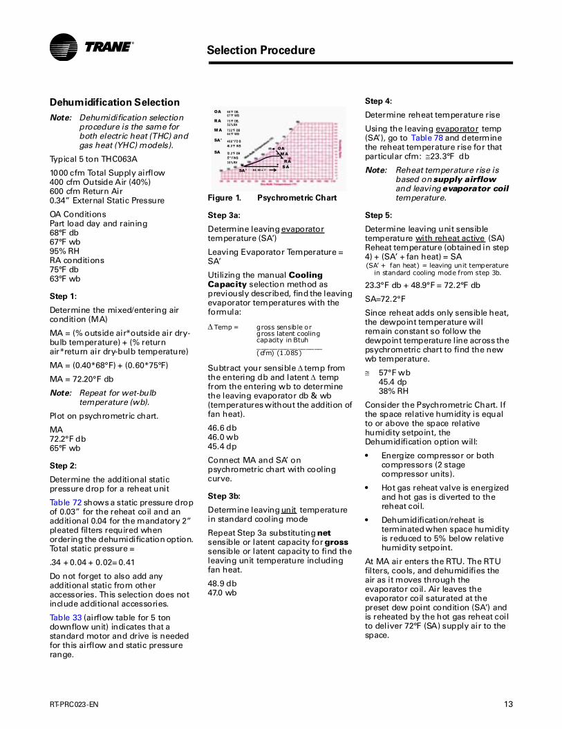
Figure 1. Psychrometric Chart
Δ Temp = gross sensible orgross latent coolingcapacity in Btuh________________(cfm) (1.085)
MA
SA'
RA
OA
OA
RA
68°F DB,67°F WB75°F DB,52% RH
MA 72 .2°F DB65°F WB
SA' 46 .6° F D B
SASARE HEA T
SA 72 .2°F DB57° F WB
46 .0°F WB
38% RH
Step 4:
Determine reheat temperature rise
Using the leaving evaporator temp (SA’), go to Table 78 and determine the reheat temperature rise for that particular cfm: ≅23.3°F db
Note: Reheat temperature rise is based on supply airflow and leaving evaporator coil temperature.
Step 5:
Determine leaving unit sensible temperature with reheat active (SA)Reheat temperature (obtained in step 4) + (SA’ + fan heat) = SA(SA’ + fan heat) = leaving unit temperature
in standard cooling mode from step 3b.
23.3°F db + 48.9°F = 72.2°F db
SA=72.2°F
Since reheat adds only sensible heat, the dewpoint temperature will remain constant so follow the dewpoint temperature line across the psychrometric chart to find the new wb temperature.
≅ 57°F wb45.4 dp38% RH
Consider the Psychrometric Chart. If the space relative humidity is equal to or above the space relative humidity setpoint, the Dehumidification option will:
• Energize compressor or both compressors (2 stage compressor units).
• Hot gas reheat valve is energized and hot gas is diverted to the reheat coil.
• Dehumidification/reheat is terminated when space humidity is reduced to 5% below relative humidity setpoint.
At MA air enters the RTU. The RTU filters, cools, and dehumidifies the air as it moves through the evaporator coil. Air leaves the evaporator coil saturated at the preset dew point condition (SA’) and is reheated by the hot gas reheat coil to deliver 72°F (SA) supply air to the space.
14 RT-PRC023-EN
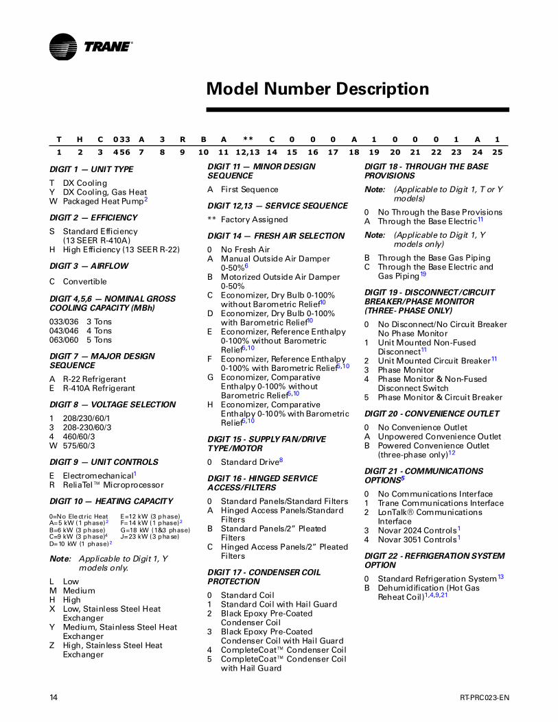
DIGIT 1 — UNIT TYPE
T DX CoolingY DX Cooling, Gas HeatW Packaged Heat Pump2
DIGIT 2 — EFFICIENCY
S Standard Efficiency (13 SEER R-410A)
H High Efficiency (13 SEER R-22)
DIGIT 3 — AIRFLOW
C Convertible
DIGIT 4,5,6 — NOMINAL GROSS COOLING CAPACITY (MBh)
033/036 3 Tons043/046 4 Tons063/060 5 Tons
DIGIT 7 — MAJOR DESIGN SEQUENCE
A R-22 RefrigerantE R-410A Refrigerant
DIGIT 8 — VOLTAGE SELECTION
1 208/230/60/13 208-230/60/34 460/60/3W 575/60/3
DIGIT 9 — UNIT CONTROLS
E Electromechanical1R ReliaTel™ Microprocessor
DIGIT 10 — HEATING CAPACITY
Note: Applicable to Digit 1, Y models only.
L LowM MediumH HighX Low, Stainless Steel Heat
ExchangerY Medium, Stainless Steel Heat
ExchangerZ High, Stainless Steel Heat
Exchanger
T H C 033 A 3 R B A ** C 0 0 0 A 1 0 0 0 1 A 1
1 2 3 456 7 8 9 10 11 12,13 14 15 16 17 18 19 20 21 22 23 24 25
0=No Ele ctric Heat E=12 kW (3 phase)A=5 kW (1 phase)2 F=14 kW (1 phase)2
B=6 kW (3 phase) G=18 kW (1&3 phase)C=9 kW (3 phase)4 J=23 kW (3 pha se)D=10 kW (1 phase)2
DIGIT 11 — MINOR DESIGN SEQUENCE
A First Sequence
DIGIT 12,13 — SERVICE SEQUENCE
** Factory Assigned
DIGIT 14 — FRESH AIR SELECTION
0 No Fresh AirA Manual Outside Air Damper
0-50%6
B Motorized Outside Air Damper 0-50%
C Economizer, Dry Bulb 0-100%without Barometric Relief10
D Economizer, Dry Bulb 0-100%with Barometric Relief10
E Economizer, Reference Enthalpy0-100% without BarometricRelief5,10
F Economizer, Reference Enthalpy0-100% with Barometric Relief5,10
G Economizer, ComparativeEnthalpy 0-100% withoutBarometric Relief5,10
H Economizer, ComparativeEnthalpy 0-100% with Barometric Relief5,10
DIGIT 15 - SUPPLY FAN/DRIVE TYPE/MOTOR
0 Standard Drive8
DIGIT 16 - HINGED SERVICE ACCESS/FILTERS
0 Standard Panels/Standard FiltersA Hinged Access Panels/Standard
FiltersB Standard Panels/2” Pleated
FiltersC Hinged Access Panels/2” Pleated
Filters
DIGIT 17 - CONDENSER COIL PROTECTION
0 Standard Coil1 Standard Coil with Hail Guard 2 Black Epoxy Pre-Coated
Condenser Coil3 Black Epoxy Pre-Coated
Condenser Coil with Hail Guard4 CompleteCoat™ Condenser Coil5 CompleteCoat™ Condenser Coil
with Hail Guard
DIGIT 18 - THROUGH THE BASE PROVISIONS
Note: (Applicable to Digit 1, T or Y models)
0 No Through the Base ProvisionsA Through the Base Electric11
Note: (Applicable to Digit 1, Y models only)
B Through the Base Gas PipingC Through the Base Electric and
Gas Piping19
DIGIT 19 - DISCONNECT/CIRCUIT BREAKER/PHASE MONITOR (THREE- PHASE ONLY)
0 No Disconnect/No Circuit BreakerNo Phase Monitor
1 Unit Mounted Non-Fused Disconnect11
2 Unit Mounted Circuit Breaker11
3 Phase Monitor4 Phase Monitor & Non-Fused
Disconnect Switch5 Phase Monitor & Circuit Breaker
DIGIT 20 - CONVENIENCE OUTLET
0 No Convenience OutletA Unpowered Convenience OutletB Powered Convenience Outlet
(three-phase only)12
DIGIT 21 - COMMUNICATIONS OPTIONS5
0 No Communications Interface1 Trane Communications Interface2 LonTalk® Communications
Interface3 Novar 2024 Controls1
4 Novar 3051 Controls1
DIGIT 22 - REFRIGERATION SYSTEM OPTION
0 Standard Refrigeration System13
B Dehumidification (Hot GasReheat Coil)1,4,9,21
Model Number Description

RT-PRC023-EN 15
Model Number Description
DIGIT 23 - REFRIGERATION CONTROLS
Note: Applicable to Digit 7 = A
0 No Refrigeration Control72 Frostat14
3 Crankcase Heater36 Frostat14 and Crankcase Heater3
Note: Applicable to Digit 7 = E
0 No Refrigeration Control71 Frostat14
2 Crankcase Heater33 Frostat14 and Crankcase Heater3
DIGIT 24 - SMOKE DETECTOR5,20
0 No Smoke DetectorA Return Air Smoke Detector15,16
B Supply Air Smoke DetectorC Supply and Return Air Smoke
Detectors15,16
DIGIT 25 - MONITORING CONTROLS5
0 No Monitoring Control17
1 Clogged Filter Switch17
2 Fan Failure Switch17
3 Discharge Air Sensing Tube17
4 Clogged Filter Switch and FanFail Switch17
5 Clogged Filter Switch andDischarge Air Sensing Tube17
6 Fan Fail Switch and Discharge AirSensing Tube17
7 Clogged Filter and Fan FailSwitches and Discharge AirSensing Tube17
8 Novar Return Air Sensor18
Model Number Notes
1. Not available for 3-5 tons, R-410A Heat Pumps.
2. Available for R-410A units only.
3. Standard on 4 tons, 3-phase Heat Pumps and 5 ton Heat Pumps.
4. Available for R-22 units only.
5. Not available with electromechanical controls.
6. Manual outside air damper will ship factory supplied within the unit, but must be field installed.
7. High pressure control is standard on all units.
8. Multispeed direct drive standard on single-phase. Belt drive standard on three-phase.
9. Requires the use of 2" pleated filters.
10. Economizer with Barometric Relief is for downflow configured units only. Order Economizer without Barometric Relief for horizontal configuration. Barometric Relief for horizontal configured units must be ordered as field installed accessory.
11. Through the base electric required when ordering disconnect/circuit breaker options.
12. Requires use of Disconnect or Circuit Breaker.
13. Standard metering devices are TXVs.
14. Frostat cannot be field installed in electro-mechanical units.
15. The return air smoke detector may not fit up or work properly on the Precedent units when used in conjunction with 3rd party accessories such as bolt on heat wheels, economizers and power exhaust. Do not order the return air smoke detectors when using this type of accessory.
16. Return Air Smoke Detector cannot be ordered with Novar Controls.
17. These options are standard when ordering Novar Controls.
18. This option is used when ordering Novar Controls.
19. Includes gas piping and shutoff (field assembly required).
20. Not available with high temperature stat accessory.
21. Requires hinged access panels.

16 RT-PRC023-EN
General Data
Table 1. General Data — 3-5 Tons — R-22 Refrigerant
3 Tons 4 Tons 5 Tons
T/YHC033A3,4,W T/YHC043A3,4,W T/YHC063A3,4,W
Cooling Performance(1)
Gross Cooling CapacitySEER(2)
Nominal CFM / ARI Rated CFMARI Net Cooling CapacitySystem Power (kW)
38,00013.0
1,200/1,20036,600
3.33
49,80013.0
1,600/1,60047,5004.48
62,40013.0
2,000/2,00059,500
5.56
Compressor
Number/Type 1/Scroll 1/Scroll 1/Scroll
Sound
Outdoor Sound Rating (dB)(3) 83 85 84
Outdoor Coil
TypeTube Size (in.)Face Area (sq. ft.)Rows/FPI
Lanced0.3125
7.192/17
Lanced0.31259.593/17
Lanced0.312510.963/17
Indoor Coil
TypeTube Size (in.)Face Area (sq. ft.)Rows/FPIRefrigerant ControlDrain Connection Number/Size (in.)
Lanced0.3125
6.683/16
Thermal Expansion Valve1¾ NPT
Lanced0.31256.684/16
Thermal Expansion Valve1¾ NPT
Lanced0.3125
7.714/16
Thermal Expansion Valve1¾ NPT
Outdoor Fan
TypeNumber Used/Diameter (in.)Drive Type/No. Speeds(4 )
CFMNumber Motors/HPMotor RPM
Propeller1/22
Direct/12,5501/0.201,115
Propeller1/22
Direct/13,0501/0.331,115
Propeller1/22
Direct/13,3701/0.331,115
Belt Drive Indoor Fan
TypeNumber Used/Diameter (in.)Drive Type/Number SpeedsNumber MotorsMotor HPStandard Motor RPMMotor Frame Size
FC Centrifugal1/11x11
Belt/Variable Sheave1
1.001,750
56
FC Centrifugal1/11x11
Belt/Variable Sheave1
1.001,750
56
FC Centrifugal1/11x11
Belt/Variable Sheave1
1.001,750
56
Filters(5),(6)
Type FurnishedNumber Size Recommended
Throwaway(2) 20x25x1
Throwaway(2) 20x25x1
Throwaway(2) 20x30x1(7)
Optional Hot Gas Reheat Coil
TypeTube Size (in.) ODFace Area (sq. ft.)Rows/FPI
Lanced0.3752.221/16
Lanced0.3752.221/16
Lanced0.3752.222/16
Refrigerant Charge(Lbs. of R-22)(8)
StandardOptional Hot Gas Reheat Coil
5.35.3
7.78.5
8.410.7
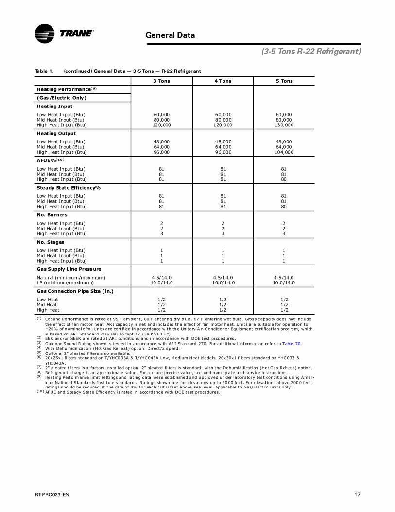
RT-PRC023-EN 17
General Data
Heating Performance( 9)
(Gas/Electric Only)
Heating Input
Low Heat Input (Btu)Mid Heat Input (Btu)High Heat Input (Btu)
60,00080,000120,000
60,00080,000
120,000
60,00080,000130,000
Heating Output
Low Heat Input (Btu)Mid Heat Input (Btu)High Heat Input (Btu)
48,00064,00096,000
48,00064,00096,000
48,00064,000104,000
AFUE%(10)
Low Heat Input (Btu)Mid Heat Input (Btu)High Heat Input (Btu)
818181
818181
818180
Steady State Efficiency%
Low Heat Input (Btu)Mid Heat Input (Btu)High Heat Input (Btu)
818181
818181
818180
No. Burners
Low Heat Input (Btu)Mid Heat Input (Btu)High Heat Input (Btu)
223
223
223
No. Stages
Low Heat Input (Btu)Mid Heat Input (Btu)High Heat Input (Btu)
111
111
111
Gas Supply Line Pressure
Natural (minimum/maximum)LP (minimum/maximum)
4.5/14.010.0/14.0
4.5/14.010.0/14.0
4.5/14.010.0/14.0
Gas Connection Pipe Size (in.)
Low HeatMid HeatHigh Heat
1/21/21/2
1/21/21/2
1/21/21/2
(1) Cooling Performance is rated at 95 F am bient, 80 F entering dry b ulb, 67 F entering wet bulb. Gross capacity does not include the ef fect of f an motor heat. ARI capacity is net and inc lu des the effec t of fan motor heat. Units are su itable for operation to ±20% of n ominal c fm. Units are certif ied in accordance with th e Unitary A ir-Conditioner Equipment certification prog ram, which is based on ARI Standard 210/240 except AK (380V/60 Hz).
(2) EER an d/or SEER are rated at ARI condit ions and in accordance with DOE test procedures .(3) Outdoor Sound Rating shown is tes ted in accordance with ARI Stan dard 270. For addit ional inform ation refer to Table 70.(4) With Dehumidification (Hot Gas Reheat) option: Direct/2 speed.(5) Optional 2” pleated filters also available.(6) 20x25x1 filters standard on T/YHC0 33A & T/YHC043A Low, Medium Heat Models. 20x30x1 f ilters s tandard on YHC033 &
YHC043A.(7) 2" pleated f ilters is a factory ins talled option. 2" pleated filters is standard with the Dehumidification (Hot Gas Reh eat) option.(8) Refrigerant charge is an approximate value. For a more prec ise value, see unit n am eplate and service ins truc tions.(9) Heating Perform ance limit sett ings and rating data were es tablished and approved un der laboratory tes t conditions using Amer-
ican National S tandards Ins titute s tandards. Ratings shown are for elevations up to 20 00 feet. For elevations above 200 0 feet, ratings should be reduced at the rate of 4% for each 100 0 feet above sea level. Applicable to Gas/Electric units only.
(10 ) AFUE and S teady S tate Effic iency is rated in accordance with DOE test procedures.
Table 1. (continued) General Data — 3-5 Tons — R-22 Refrigerant
3 Tons 4 Tons 5 Tons
(3-5 Tons R-22 Refrigerant)

18 RT-PRC023-EN
General Data
Table 2. General Data — 3-4Tons — R-410A Refrigerant
3 Tons 4 Tons
T/YSC036E1 T/YSC036E3,4,W T/YSC048E1 T/YSC048E3,4,W
Cooling Performance(1)
Gross Cooling CapacitySEER(2)
Nominal CFM / ARI Rated CFMARI Net Cooling CapacitySystem Power (kW)
35,62013.0
1,200/1,20035,000
3.04
37,15013.0
1,200/1,20035,800
3.20
49,21013.0
1,600/1,60048,000
4.32
49,45013.0
1,600/1,60048,000
4.39
Compressor
Number/Type 1/Scroll 1/Scroll 1/Scroll 1/Scroll
Sound
Outdoor Sound Rating (dB)(3) 81 81 82 82
Outdoor Coil
TypeTube Size (in.) ODFace Area (sq. ft.)Rows/FPI
Lanced0.312510.962/17
Lanced0.3125
9.592/17
Lanced0.312510.962/17
Lanced0.312510.962/17
Indoor Coil
TypeTube Size (in.)Face Area (sq. ft.)Rows/FPIRefrigerant ControlDrain Connection Number/Size (in.)
Lanced0.3125
7.713/16
Thermal Expansion Valve1¾ NPT
Lanced0.3125
7.713/16
Thermal Expansion Valve1¾ NPT
Lanced0.3125
7.714/16
Thermal Expansion Valve1¾ NPT
Lanced0.3125
7.714/16
Thermal Expansion Valve1¾ NPT
Outdoor Fan
TypeNumber Used/Diameter (in.)Drive Type/No. SpeedsCFMMotor HPMotor RPM
Propeller1/22
Direct/13,4660.331,075
Propeller1/22
Direct/13,3750.331,075
Propeller1/22
Direct/13,4110.331,075
Propeller1/22
Direct/13,4030.331,075
Indoor Fan
Type (Standard)Number Used/Diameter (in.)Drive Type/Number SpeedsNumber MotorsMotor HPMotor Frame Size
FC Centrifugal1/11x11Direct/5
10.7548
FC Centrifugal1/11x11
Belt/Variable1
1.056
FC Centrifugal1/11x11Direct/5
11.048
FC Centrifugal1/11x11
Belt/Variable1
1.056
Filters(4)
Type FurnishedNumber Size Recommended
Throwaway(2) 20x30x1
Throwaway(2) 20x30x1
Throwaway(2) 20x30x1
Throwaway(2) 20x30x1
Refrigerant Charge (Lbs. of R-410A)(5)
Pounds of R-410A 6.3 6.3 7.4 7.4
(3-4 Tons R-410A Refrigerant)

RT-PRC023-EN 19
General Data
(3-4 Tons R-410A Refrigerant)
Heating Performance( 6)
(Gas/Electric Only)
Heating Input
Low Heat Input (Btu)Mid Heat Input (Btu)High Heat Input (Btu)
60,00080,000120,000
60,00080,000120,000
60,00080,000120,000
60,00080,000120,000
Heating Output
Low Heat Input (Btu)Mid Heat Input (Btu)High Heat Input (Btu)
47,00065,00094,000
48,00064,00096,000
49,00065,00095,000
48,00064,00096,000
AFUE%(7)
Low Heat Input (Btu)Mid Heat Input (Btu)High Heat Input (Btu)
798079
808080
808079
808080
Steady State Efficiency%
Low Heat Input (Btu)Mid Heat Input (Btu)High Heat Input (Btu)
808180
808080
818180
808080
No. Burners
Low Heat Input (Btu)Mid Heat Input (Btu)High Heat Input (Btu)
223
223
223
223
No. Stages
Low Heat Input (Btu)Mid Heat Input (Btu)High Heat Input (Btu)
111
111
111
111
Gas Supply Line Pressure
Natural (minimum/maximum)LP (minimum/maximum)
4.5/10.510.0/13.0
4.5/10.510.0/13.0
4.5/10.510.0/13.0
4.5/10.510.0/13.0
Gas Connection Pipe Size (in)
Low Heat Mid HeatHigh Heat
1/21/21/2
1/21/21/2
1/21/21/2
1/21/21/2
(1) Cooling Perform ance is rated at 95 F am bien t, 80 F entering dry bulb, 6 7 F entering wet bulb. Gross capacity does not include the effect of fan motor heat. ARI capac ity is net and includes the effect of f an motor heat. Units are suitable for operation to ±20% of nominal c fm. Units are certif ied in accordan ce with the Unitary A ir-Conditioner Equipment certif ication p rogram, which is based on ARI S tandard 210/2 40 except AK (380V/60 Hz).
(2) EER an d/or SEER are rated at ARI condit ions and in accordance with DOE test procedures .(3) Outdoor Sound Rating shown is tes ted in accordance with ARI Stan dard 270. For addit ional inform ation refer to Table 70.(4) Optional 2” pleated filters also available.(5) Refrigerant charge is an approximate value. For a more prec ise value, see unit n am eplate and service ins truc tions.(6) Heating Performance limit settings and rating data were es tablished and ap proved und er laboratory test condit ions us ing American National Standards In-
stitute stan dards . Ratings show n are for elevations up to 2000 feet. For elevations ab ove 2 000 feet, ratin gs should be reduced a t the rate of 4% for each 1000 feet above sea level. Applicable to Gas/Elec tric u nits only.
(7) AFUE is rated in accordance with DOE test procedures.
Table 2. (continued) General Data — 3-4Tons — R-410A Refrigerant
3 Tons 4 Tons
20 RT-PRC023-EN
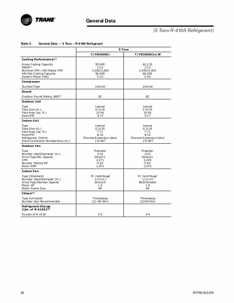
General Data
(5 Tons R-410A Refrigerant)
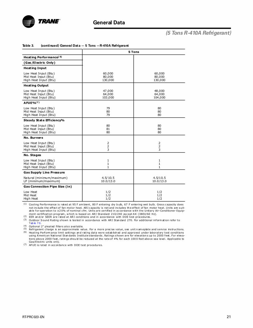
Table 3. General Data — 5 Tons —R-410A Refrigerant
5 Tons
T/YSC060E1 T/YSC060E3,4,W
Cooling Performance(1)
Gross Cooling CapacitySEER(2)
Nominal CFM / ARI Rated CFMARI Net Cooling CapacitySystem Power (kW)
59,90013.0
2,000/2,00058,0005.25
62,27013.0
2,000/2,00060,0005.46
Compressor
Number/Type 1/Scroll 1/Scroll
Sound
Outdoor Sound Rating (dB)(3) 82 82
Outdoor Coil
TypeTube Size (in.)Face Area (sq. ft.)Rows/FPI
Lanced0.312510.963/17
Lanced0.312510.963/17
Indoor Coil
TypeTube Size (in.)Face Area (sq. ft.)Rows/FPIRefrigerant ControlDrain Connection Number/Size (in.)
Lanced0.31257.714/16
Thermal Expansion Valve1¾ NPT
Lanced0.31257.714/16
Thermal Expansion Valve1¾ NPT
Outdoor Fan
TypeNumber Used/Diameter (in.)Drive Type/No. SpeedsCFMNumber Motors/HPMotor RPM
Propeller1/22
Direct/13,2710.401,075
Propeller1/22
Direct/13,2450.401,075
Indoor Fan
Type (Standard)Number Used/Diameter (in.)Drive Type/Number SpeedsMotor HPMotor Frame Size
FC Centrifugal1/11x11Direct/5
1.048
FC Centrifugal1/11x11
Belt/Variable1.056
Filters(4)
Type FurnishedNumber Size Recommended
Throwaway(2) 20x30x1
Throwaway(2)20x30x1
Refrigerant Charge (Lbs. of R-410A)(5)
Pounds of R-410A 9.5 9.4
RT-PRC023-EN 21
General Data
(5 Tons R-410A Refrigerant)
Heating Performance( 6)
(Gas/Electric Only)
Heating Input
Low Heat Input (Btu)Mid Heat Input (Btu)High Heat Input (Btu)
60,00080,000130,000
60,00080,000130,000
Heating Output
Low Heat Input (Btu)Mid Heat Input (Btu)High Heat Input (Btu)
47,00064,000103,000
48,00064,000104,000
AFUE%(7)
Low Heat Input (Btu)Mid Heat Input (Btu)High Heat Input (Btu)
798079
808080
Steady State Efficiency%
Low Heat Input (Btu)Mid Heat Input (Btu)High Heat Input (Btu)
808180
808080
No. Burners
Low Heat Input (Btu)Mid Heat Input (Btu)High Heat Input (Btu)
223
223
No. Stages
Low Heat Input (Btu)Mid Heat Input (Btu)High Heat Input (Btu)
111
111
Gas Supply Line Pressure
Natural (minimum/maximum)LP (minimum/maximum)
4.5/10.510.0/13.0
4.5/10.510.0/13.0
Gas Connection Pipe Size (in)
Low HeatMid HeatHigh Heat
1/21/21/2
1/21/21/2
(1) Cooling Performance is rated at 95 F am bient, 80 F entering dry b ulb, 67 F entering wet bulb. Gross capacity does not inc lude the effec t of fan motor heat. ARI capacity is net and inc ludes th e ef fect of fan motor heat. Units are suit-ab le for operation to ±2 0% of nominal c fm. Units are certif ied in accordance w ith the Unitary Air-Conditioner Equip-ment certification program , w hich is based on ARI Standard 210/240 except AK (380V/60 Hz).
(2) EER an d/or SEER are rated at ARI condit ions and in accordance with DOE test procedures .(3) Outdoor Sound Rating shown is tes ted in accordance with ARI Stan dard 270. For addit ional inform ation refer to
Tab le 7 0.(4) Optional 2” pleated filters also available.(5) Refrigerant charge is an approximate value. For a more prec ise value, see unit n am eplate and service ins truc tions.(6) Heating Perform ance limit sett ings an d rating data were estab lish ed and approved under laboratory test condit ions
using American National Stan dards Institute s tandards . Ratings shown are for elevation s up to 2000 feet. For eleva-tions above 2000 feet, ratin gs shou ld be reduced at the rate of 4% for each 100 0 feet above sea level. Applicable to Gas/Electric units only.
(7) AFUE is rated in accordance with DOE test procedures.
Table 3. (continued) General Data — 5 Tons —R-410A Refrigerant
5 Tons
22 RT-PRC023-EN
General Data
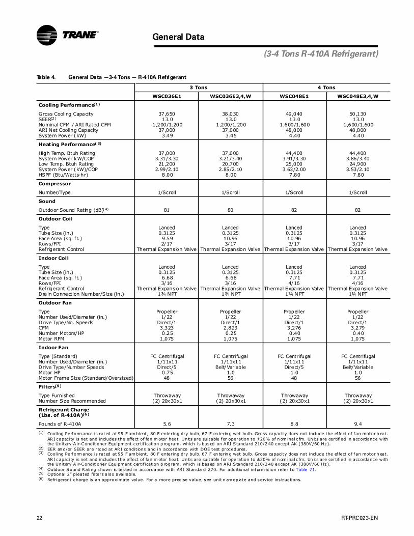
(3-4 Tons R-410A Refrigerant)
Table 4. General Data —3-4 Tons — R-410A Refrigerant
3 Tons 4 Tons
WSC036E1 WSC036E3,4,W WSC048E1 WSC048E3,4,W
Cooling Performance(1)
(1) Cooling Perform ance is rated at 95 F am bient, 80 F entering dry bulb, 67 F en terin g wet bulb. Gross capacity does not include the ef fect of f an motor h eat. ARI capac ity is net and includes the effect of fan m otor heat. Units are suitable for operation to ±20% of n om inal c fm. Un its are certified in accordance with the Unitary A ir-Conditioner Equipment certif ication p rogram, which is based on ARI S tandard 210/2 40 except AK (380V/60 Hz).
Gross Cooling CapacitySEER(2)
Nominal CFM / ARI Rated CFMARI Net Cooling Capacity System Power (kW)
(2) EER an d/or SEER are rated at ARI condit ions and in accordance with DOE test procedures .
37,65013.0
1,200/1,20037,000
3.49
38,03013.0
1,200/1,20037,000
3.45
49,04013.0
1,600/1,60048,000
4.40
50,13013.0
1,600/1,60048,800
4.40
Heating Performance( 3)
(3) Cooling Perform ance is rated at 95 F am bient, 80 F entering dry bulb, 67 F en terin g wet bulb. Gross capacity does not include the ef fect of f an motor h eat. ARI capac ity is net and includes the effect of fan m otor heat. Units are suitable for operation to ±20% of n om inal c fm. Un its are certified in accordance with the Unitary A ir-Conditioner Equipment certif ication p rogram, which is based on ARI S tandard 210/2 40 except AK (380V/60 Hz).
High Temp. Btuh RatingSystem Power kW/COPLow Temp. Btuh RatingSystem Power (kW)/COPHSPF (Btu/Watts-hr)
37,0003.31/3.30
21,2002.99/2.10
8.00
37,0003.21/3.40
20,7002.85/2.10
8.00
44,4003.91/3.30
25,0003.63/2.00
7.80
44,4003.86/3.40
24,9003.53/2.10
7.80
Compressor
Number/Type 1/Scroll 1/Scroll 1/Scroll 1/Scroll
Sound
Outdoor Sound Rating (dB)(4)
(4) Outdoor Sound Rating shown is tes ted in accordance with ARI Stan dard 270. For addit ional inform ation refer to Table 71.
81 80 82 82
Outdoor Coil
TypeTube Size (in.)Face Area (sq. ft.)Rows/FPIRefrigerant Control
Lanced0.3125
9.592/17
Thermal Expansion Valve
Lanced0.312510.963/17
Thermal Expansion Valve
Lanced0.312510.963/17
Thermal Expansion Valve
Lanced0.312510.963/17
Thermal Expansion Valve
Indoor Coil
TypeTube Size (in.)Face Area (sq. ft.)Rows/FPIRefrigerant ControlDrain Connection Number/Size (in.)
Lanced0.3125
6.683/16
Thermal Expansion Valve1¾ NPT
Lanced0.3125
6.683/16
Thermal Expansion Valve1¾ NPT
Lanced0.3125
7.714/16
Thermal Expansion Valve1¾ NPT
Lanced0.3125
7.714/16
Thermal Expansion Valve1¾ NPT
Outdoor Fan
TypeNumber Used/Diameter (in.)Drive Type/No. SpeedsCFMNumber Motors/HPMotor RPM
Propeller1/22
Direct/13,3230.25
1,075
Propeller1/22
Direct/12,8230.25
1,075
Propeller1/22
Direct/13,2760.40
1,075
Propeller1/22
Direct/13,2790.40
1,075
Indoor Fan
Type (Standard)Number Used/Diameter (in.)Drive Type/Number SpeedsMotor HPMotor Frame Size (Standard/Oversized)
FC Centrifugal1/11x11Direct/5
0.7548
FC Centrifugal1/11x11
Belt/Variable1.056
FC Centrifugal1/11x11Direct/5
1.048
FC Centrifugal1/11x11
Belt/Variable1.056
Filters(5)
(5) Optional 2” pleated filters also available.
Type FurnishedNumber Size Recommended
Throwaway(2) 20x30x1
Throwaway(2) 20x30x1
Throwaway(2) 20x30x1
Throwaway(2) 20x30x1
Refrigerant Charge (Lbs. of R-410A)(6)
(6) Refrigerant charge is an approximate value. For a more prec ise value, see unit n am eplate and service ins truc tions.
Pounds of R-410A 5.6 7.3 8.8 9.4

RT-PRC023-EN 23
General Data
(5 Tons R-410A Refrigerant)
Table 5. General Data —5 Tons —R-410A
5 Tons
WSC060E1 WSC060E3,4,W
Cooling Performance(1)
(1) Cooling Performance is rated at 95 F am bient, 80 F entering dry b ulb, 67 F entering wet bulb. Gross capacity does not inc lude the effec t of fan motor heat. ARI capacity is net and inc ludes th e ef fect of fan motor heat. Units are suit-ab le for operation to ±2 0% of nominal c fm. Units are certif ied in accordance w ith the Unitary Air-Conditioner Equip-ment certification program , w hich is based on ARI Standard 210/240 except AK (380V/60 Hz).
Gross Cooling CapacitySEER(2)
Nominal CFM / ARI Rated CFMARI Net Cooling CapacitySystem Power (kW)
(2) EER an d/or SEER are rated at ARI condit ions and in accordance with DOE test procedures .
58,36013.0
2,000/2,00057,0005.06
63,44013.0
2,000/2,00062,0005.13
Heating Performance( 3)
(3) Cooling Performance is rated at 95 F am bient, 80 F entering dry b ulb, 67 F entering wet bulb. Gross capacity does not inc lude the effec t of fan motor heat. ARI capacity is net and inc ludes th e ef fect of fan motor heat. Units are suit-ab le for operation to ±2 0% of nominal c fm. Units are certif ied in accordance w ith the Unitary Air-Conditioner Equip-ment certification program , w hich is based on ARI Standard 210/240 except AK (380V/60 Hz).
High Temp. Btuh RatingSystem Power kW/COPLow Temp. Btuh RatingSystem Power kW/COPHSPF (Btu/Watts-hr)
58,5004.86/3.50
34,5004.46/2.30
8.00
58,5004.94/3.50
34,4004.44/2.30
8.00
Compressor
Number/Type 1/Scroll 1/Scroll
Sound
Outdoor Sound Rating (dB)(4)
(4) Outdoor Sound Rating shown is tes ted in accordance with ARI Stan dard 270. For addit ional inform ation refer to Tab le 7 1.
87 87
Outdoor Coil
TypeTube Size (in.)Face Area (sq. ft.)Rows/FPIRefrigerant Control
Lanced0.312517.003/17
Thermal Expansion Valve
Lanced0.312517.003/17
Thermal Expansion Valve
Indoor Coil
TypeTube Size (in.)Face Area (sq. ft.)Rows/FPIRefrigerant ControlDrain Connection Number/Size (in.)
Lanced0.31259.273/16
Thermal Expansion Valve1¾ NPT
Lanced0.31259.273/16
Thermal Expansion Valve1¾ NPT
Outdoor Fan
TypeNumber Used/Diameter (in.)Drive Type/No. SpeedsCFMMotor HPMotor RPM
Propeller1/26
Direct/15,1450.401,075
Propeller1/26
Direct/15,1380.401,075
Indoor Fan
Type (Standard)Number Used/Diameter (in.)Drive Type/Number SpeedsMotor HPMotor Frame Size
FC Centrifugal1/11x11Direct/5
1.0048
FC Centrifugal1/11x11
Belt/Variable1.0056
Filters(5)
(5) Optional 2” pleated filters also available.
Type FurnishedNumber Size Recommended
Throwaway(2) 20x30x1
Throwaway(4) 16x25x2
Refrigerant Charge(Lbs. of R-410A)(6)
(6) Refrigerant charge is an approximate value. For a more prec ise value, see unit n am eplate and service ins truc tions.
Pounds of R-410A 10.0 10.6

24 RT-PRC023-EN
Table 6. Gross Cooling Capacit ies 3 Tons T/YHC033A3,4,W Standard Refrigerat ion or Dehumidification (Hot Gas Reheat)
Ambient Temperature
85 95 105 115
Air Ent Entering Wet Bulb
Flow DB 61 67 73 61 67 73 61 67 73 61 67 73
CFM (F) MBH SHC MBH SHC MBH SHC MBH SHC MBH SHC MBH SHC MBH SHC MBH SHC MBH SHC MBH SHC MBH SHC MBH SHC
600* 75 30.8 21.6 34.9 17.8 39.2 13.7 28.9 20.4 32.8 16.6 37.0 12.5 26.9 19.1 30.6 15.3 34.7 11.3 24.8 17.8 28.4 14.1 32.3 10.0
80 30.9 25.0 35.0 21.2 39.3 17.2 29.0 23.8 32.9 19.9 37.1 16.0 26.9 22.5 30.8 18.7 34.8 14.8 24.9 21.1 28.6 17.4 32.4 13.5
85 31.0 28.4 35.1 24.6 39.5 20.6 29.0 27.1 33.1 23.3 37.3 19.3 27.0 25.8 30.9 22.0 35.0 18.1 25.0 24.5 28.7 20.7 32.6 16.8
90 31.2 31.2 35.2 27.9 39.6 23.9 29.6 29.6 33.1 26.6 37.4 22.7 28.0 28.0 31.0 25.4 35.1 21.4 26.3 26.3 28.8 24.0 32.7 20.1
780* 75 33.1 24.8 37.3 19.7 41.8 14.5 30.9 23.5 35.0 18.5 39.3 13.2 28.8 22.2 32.6 17.1 36.7 12.0 26.5 20.8 30.2 15.8 34.1 10.7
80 33.2 29.2 37.4 24.1 41.9 18.9 31.1 27.9 35.1 22.8 39.5 17.6 29.0 26.6 32.8 21.5 36.9 16.3 26.7 25.2 30.4 20.1 34.3 15.0
85 33.4 33.4 37.5 28.4 42.1 23.2 31.6 31.6 35.3 27.1 39.6 21.9 29.8 29.8 32.9 25.8 37.0 20.6 27.9 27.9 30.5 24.4 34.4 19.3
90 35.4 35.4 37.7 32.7 42.2 27.5 33.6 33.6 35.5 31.4 39.8 26.2 31.8 31.8 33.1 30.1 37.2 24.9 29.8 29.8 30.8 28.7 34.6 23.6
960 75 34.6 27.8 38.9 21.5 43.4 15.1 32.4 26.5 36.5 20.2 40.9 13.8 30.1 25.1 34.0 18.9 38.1 12.6 27.7 23.7 31.4 17.5 35.3 11.2
80 35.0 33.2 39.0 26.8 43.5 20.4 32.8 31.9 36.6 25.5 41.0 19.2 30.6 30.5 34.1 24.1 38.3 17.8 28.3 28.3 31.6 22.7 35.5 16.5
85 36.4 36.4 39.2 32.0 43.7 25.6 34.5 34.5 36.8 30.7 41.2 24.4 32.5 32.5 34.4 29.4 38.5 23.0 30.4 30.4 31.9 28.0 35.7 21.7
90 38.6 38.6 39.6 37.3 43.9 30.8 36.7 36.7 37.3 36.0 41.4 29.5 34.6 34.6 34.9 34.7 38.6 28.2 32.5 32.5 32.5 32.5 35.9 26.8
1080 75 35.5 29.7 39.7 22.9 44.1 15.4 33.2 28.4 37.2 21.6 41.6 14.2 30.8 27.0 34.6 20.3 38.8 12.9 28.4 25.6 32.0 18.9 35.9 11.6
80 36.0 35.8 39.9 28.5 44.3 21.3 33.8 33.8 37.4 27.2 41.7 20.1 31.7 31.7 34.8 25.8 39.0 18.8 29.6 29.6 32.2 24.4 36.1 17.4
85 38.1 38.1 40.1 34.4 44.5 27.2 36.0 36.0 37.7 33.1 41.9 25.9 33.9 33.9 35.2 31.7 39.2 24.6 31.8 31.8 32.6 30.3 36.3 23.2
90 40.4 40.4 40.8 40.4 44.7 33.0 38.3 38.3 38.3 38.3 42.1 31.7 36.2 36.2 36.2 36.2 39.4 30.4 34.0 34.0 33.9 33.9 36.5 29.0
1200 75 36.2 31.6 40.4 23.7 44.8 15.7 33.8 30.2 37.8 22.4 42.2 14.5 31.4 28.8 35.2 21.0 39.4 13.2 29.0 27.4 32.5 19.6 36.4 11.9
80 37.1 37.1 40.6 30.2 45.0 22.3 35.0 35.0 38.0 28.8 42.3 21.0 32.9 32.9 35.4 27.5 39.6 19.7 30.7 30.7 32.7 26.1 36.6 18.3
85 39.5 39.5 41.0 36.7 45.1 28.7 37.4 37.4 38.4 35.4 42.5 27.4 35.2 35.2 35.9 34.0 39.8 26.1 33.0 33.0 33.3 32.7 36.8 24.7
90 42.0 42.0 42.0 42.0 45.4 35.1 39.8 39.8 39.8 39.8 42.8 33.8 37.5 37.5 37.5 37.5 40.1 32.5 35.2 35.2 35.2 35.2 37.1 31.1
1320 75 36.8 33.4 40.9 24.8 45.3 16.1 34.4 32.1 38.3 23.4 42.6 14.8 32.0 30.7 35.6 22.0 39.9 13.5 29.6 29.3 32.9 20.6 36.9 12.2
80 38.3 38.3 41.2 31.9 45.5 23.1 36.1 36.1 38.6 30.5 42.8 21.9 33.9 33.9 35.9 29.1 40.0 20.6 31.7 31.7 33.2 27.7 37.1 19.2
85 40.8 40.8 41.7 39.0 45.7 30.2 38.6 38.6 39.2 37.7 43.0 28.9 36.3 36.3 36.6 36.3 40.2 27.5 34.0 34.0 34.0 34.0 37.3 26.2
90 43.3 43.3 43.3 43.3 46.0 37.1 41.1 41.1 41.1 41.1 43.3 35.9 38.8 38.8 38.8 38.8 40.6 34.6 36.3 36.3 36.3 36.3 37.7 33.2
1440 75 37.4 35.2 41.4 25.8 45.8 16.4 35.0 33.9 38.7 24.4 43.0 15.1 32.6 32.5 36.0 23.0 40.2 13.8 30.1 30.1 33.2 21.6 37.2 12.5
80 39.3 39.3 41.7 33.5 46.0 24.0 37.1 37.1 39.1 32.1 43.2 22.7 34.8 34.8 36.4 30.7 40.4 21.4 32.5 32.5 33.6 29.3 37.4 20.0
85 41.9 41.9 42.4 41.3 46.1 31.6 39.7 39.7 39.6 39.6 43.4 30.3 37.3 37.3 37.3 37.3 40.6 29.0 34.9 34.9 34.9 34.9 37.7 27.6
90 44.4 44.4 44.4 44.4 46.5 39.2 42.2 42.2 42.2 42.2 43.8 37.9 39.8 39.8 39.8 39.8 41.1 36.6 37.3 37.3 37.3 37.3 38.2 35.3Notes:
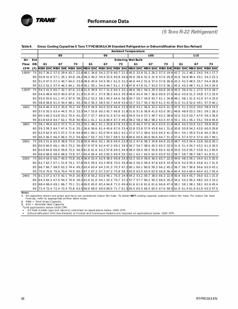
1. A ll capacities show n are gross an d have not considered indoor fan h eat. To obtain NET cooling capacity subtrac t indoor fan heat. For indoor fan heat form ula, refer to appropriate airflow table notes .
2. MBH = Total Gross Capacity3. SHC = Sens ible Heat Capac ity*Unit applications below 96 0 CFM• A ll heat m odels (gas and elec tric) restric ted on applications below 960 CFM.• Dehum idif ication (Hot Gas Reheat) or Frostat an d Crankcase Heaters are required on applications below 960 CFM.
Performance Data

RT-PRC023-EN 25
Performance Data
Table 7. Gross Cooling Capacit ies 4 Tons T/YHC043A3,4,W Standard Refrigerat ion or Dehumidification (Hot Gas Reheat)
Ambient Temperature
85 95 105 115
Air Ent Entering Wet Bulb
Flow DB 61 67 73 61 67 73 61 67 73 61 67 73
CFM (F) MBH SHC MBH SHC MBH SHC MBH SHC MBH SHC MBH SHC MBH SHC MBH SHC MBH SHC MBH SHC MBH SHC MBH SHC
800* 75 40.4 29.1 45.7 23.7 51.3 18.2 38.2 27.7 43.3 22.4 48.8 16.9 35.8 26.3 40.6 20.9 45.9 15.4 33.3 24.8 38.0 19.5 43.1 14.0
80 40.5 33.8 45.8 28.4 51.5 22.8 38.3 32.4 43.4 27.0 48.9 21.5 35.9 31.0 40.8 25.5 46.0 20.0 33.4 29.5 38.1 24.1 43.2 18.6
85 40.8 38.5 45.9 33.1 51.6 27.5 38.5 37.1 43.5 31.7 49.0 26.1 36.2 35.7 40.8 30.2 46.1 24.6 33.9 33.9 38.2 28.7 43.3 23.2
90 42.0 42.0 46.1 37.7 51.7 32.1 40.1 40.1 43.7 36.3 49.1 30.7 38.1 38.1 41.0 34.8 46.2 29.2 36.1 36.1 38.4 33.3 43.4 27.8
1040* 75 43.3 33.5 48.8 26.4 54.6 19.2 40.8 32.1 46.2 25.0 51.8 17.8 38.2 30.6 43.2 23.5 48.6 16.3 35.5 29.1 40.4 22.0 45.5 14.9
80 43.6 39.6 48.9 32.4 54.7 25.1 41.1 38.2 46.3 31.0 51.9 23.8 38.6 36.7 43.3 29.5 48.7 22.3 36.0 35.2 40.5 28.0 45.7 20.8
85 44.7 44.7 49.1 38.4 54.9 31.1 42.6 42.6 46.5 37.0 52.1 29.7 40.4 40.4 43.6 35.4 48.8 28.2 38.2 38.2 40.7 33.9 45.8 26.7
90 47.3 47.3 49.4 44.4 55.0 37.0 45.2 45.2 46.8 42.9 52.2 35.6 43.0 43.0 44.0 41.4 49.0 34.0 40.7 40.7 41.2 39.9 46.0 32.6
1280 75 45.3 37.7 50.8 28.9 56.7 20.0 42.7 36.2 48.0 27.5 53.8 18.6 40.0 34.7 44.9 25.9 50.3 17.0 37.2 33.1 41.9 24.4 47.1 15.6
80 46.0 45.1 51.0 36.2 56.9 27.3 43.4 43.4 48.2 34.7 53.9 25.9 41.1 41.1 45.1 33.1 50.5 24.3 38.7 38.7 42.1 31.6 47.3 22.9
85 48.5 48.5 51.3 43.5 57.0 34.5 46.2 46.2 48.6 42.0 54.1 33.1 43.9 43.9 45.5 40.4 50.6 31.5 41.4 41.4 42.6 38.9 47.5 30.0
90 51.4 51.4 52.1 50.8 57.3 41.7 49.1 49.1 49.5 49.4 54.3 40.3 46.7 46.7 46.7 46.7 50.9 38.7 44.2 44.2 44.2 44.2 47.7 37.2
1440 75 46.3 40.3 51.5 30.3 57.4 20.3 43.7 38.8 48.7 28.9 54.3 18.9 41.0 37.3 45.7 27.4 51.2 17.5 38.1 35.8 42.7 25.9 47.9 16.0
80 47.6 47.6 51.8 38.5 57.6 28.5 45.2 45.2 49.0 37.0 54.5 27.1 42.8 42.8 46.0 35.5 51.3 25.6 40.3 40.3 43.0 34.0 48.1 24.2
85 50.6 50.6 52.3 46.6 57.7 36.5 48.2 48.2 49.5 45.2 54.7 35.1 45.7 45.7 46.6 43.7 51.5 33.7 43.2 43.2 43.7 42.2 48.3 32.2
90 53.6 53.6 53.6 53.6 58.1 44.6 51.2 51.2 51.2 51.2 55.0 43.2 48.7 48.7 48.7 48.7 51.9 41.7 46.1 46.1 46.1 46.1 48.7 40.2
1600 75 47.3 42.9 52.4 31.8 58.2 20.7 44.6 41.4 49.4 30.4 55.1 19.3 41.8 39.9 46.4 28.9 51.9 17.9 39.0 38.4 43.3 27.4 48.6 16.4
80 49.2 49.2 52.7 40.9 58.4 29.8 46.8 46.8 49.8 39.4 55.3 28.4 44.3 44.3 46.8 37.9 52.0 26.9 41.7 41.7 43.7 36.4 48.7 25.4
85 52.4 52.4 53.4 49.9 58.6 38.7 49.9 49.9 50.6 48.5 55.5 37.3 47.4 47.4 47.7 47.0 52.3 35.8 44.7 44.7 44.7 44.7 49.0 34.3
90 55.6 55.6 55.6 55.6 59.1 47.6 53.1 53.1 53.1 53.1 56.0 46.2 50.4 50.4 50.4 50.4 52.8 44.7 47.7 47.7 47.7 47.7 49.5 43.2
1760 75 48.2 45.5 53.0 33.3 59.0 21.2 45.5 44.0 50.1 31.8 55.8 19.8 42.7 42.5 47.0 30.3 52.5 18.3 39.9 39.9 43.8 28.8 49.1 16.8
80 50.7 50.7 53.5 43.2 59.1 31.1 48.2 48.2 50.5 41.7 55.9 29.6 45.6 45.6 47.5 40.2 52.6 28.2 42.9 42.9 44.4 38.7 49.3 26.7
85 54.0 54.0 54.4 53.1 59.4 40.8 51.4 51.4 51.4 51.4 56.2 39.4 48.8 48.8 48.8 48.8 52.9 37.9 46.0 46.0 46.0 46.0 49.6 36.4
90 57.3 57.3 57.3 57.3 59.9 50.5 54.7 54.7 54.7 54.7 56.8 49.1 52.0 52.0 52.0 52.0 53.6 47.6 49.2 49.2 49.2 49.2 50.3 46.1
1920 75 49.0 48.1 53.6 34.7 59.6 21.6 46.1 46.1 50.6 33.3 56.3 20.2 43.6 43.6 47.5 31.8 53.0 18.7 40.9 40.9 44.3 30.2 49.5 17.2
80 52.0 52.0 54.2 45.4 59.7 32.3 49.4 49.4 51.2 44.0 56.5 30.9 46.8 46.8 48.1 42.5 53.2 29.4 44.0 44.0 45.0 41.0 49.7 27.9
85 55.4 55.4 55.3 55.3 60.0 42.9 52.7 52.7 52.7 52.7 56.9 41.5 50.0 50.0 50.0 50.0 53.5 40.0 47.2 47.2 47.2 47.2 50.1 38.5
90 58.8 58.8 58.8 58.8 60.7 53.4 56.1 56.1 56.1 56.1 57.6 52.0 53.3 53.3 53.3 53.3 54.4 50.6 50.4 50.4 50.4 50.4 51.0 49.1Notes:
1. A ll capacities show n are gross an d have not considered indoor fan h eat. To obtain NET cooling capacity subtrac t indoor fan heat. For indoor fan heat form ula, refer to appropriate airflow table notes .
2. MBH = Total Gross Capacity3. SHC = Sens ible Heat Capac ity*Unit applications below 12 80 CFM• A ll heat m odels (gas and elec tric) restric ted on applications below 1280 CFM.• Dehum idif ication (Hot Gas Reheat) or Frostat an d Crankcase Heaters are required on applications below 1280 CFM.
(4 Tons R-22 Refrigerant)
26 RT-PRC023-EN
Performance Data
(5 Tons R-22 Refrigerant)
Table 8. Gross Cooling Capacit ies 5 Tons T/YHC063A3,4,W Standard Refrigerat ion or Dehumidification (Hot Gas Reheat)
Ambient Temperature
85 95 105 115
Air Ent Entering Wet Bulb
Flow DB 61 67 73 61 67 73 61 67 73 61 67 73
CFM (F) MBH SHC MBH SHC MBH SHC MBH SHC MBH SHC MBH SHC MBH SHC MBH SHC MBH SHC MBH SHC MBH SHC MBH SHC
1000* 75 50.7 36.2 57.0 29.4 63.7 22.6 48.1 34.6 54.2 27.9 60.7 21.0 45.5 32.9 51.3 26.2 57.5 19.4 42.7 31.2 48.2 24.5 54.1 17.7
80 50.8 41.8 57.1 35.1 63.8 28.2 48.3 40.2 54.4 33.5 60.8 26.6 45.6 38.6 51.5 31.9 57.6 25.0 42.9 36.8 48.4 30.1 54.2 23.3
85 51.0 47.5 57.2 40.7 64.0 33.8 48.6 45.9 54.5 39.1 61.0 32.2 46.0 44.2 51.6 37.4 57.8 30.6 43.3 42.5 48.5 35.7 54.4 28.8
90 52.2 52.2 57.4 46.3 64.1 39.4 50.1 50.1 54.6 44.7 61.1 37.8 47.8 47.8 51.7 43.0 57.9 36.1 45.5 45.5 48.7 41.3 54.5 34.4
1300* 75 54.3 41.5 60.7 32.7 67.6 23.8 51.5 39.9 57.7 31.0 64.3 22.1 48.6 38.1 54.5 29.3 60.8 20.4 45.5 36.4 51.1 27.5 57.0 18.7
80 54.6 48.8 60.9 40.0 67.8 31.0 51.9 47.1 57.9 38.3 64.5 29.3 49.0 45.4 54.7 36.6 60.9 27.6 46.0 43.6 51.3 34.8 57.2 25.9
85 55.6 55.6 61.1 47.2 67.9 38.2 53.2 53.2 58.1 45.5 64.6 36.5 50.7 50.7 54.9 43.7 61.1 34.8 48.1 48.1 51.5 41.9 57.4 33.0
90 58.8 58.8 61.5 54.4 68.1 45.3 56.3 56.3 58.5 52.7 64.8 43.6 53.7 53.7 55.3 50.9 61.3 41.9 51.0 51.0 52.0 49.1 57.5 40.1
1600 75 56.8 46.5 63.2 35.6 70.2 24.7 53.9 44.9 60.0 33.9 66.6 23.0 50.8 43.1 56.6 32.2 62.9 21.3 47.5 41.3 53.0 30.4 58.9 19.5
80 57.6 55.5 63.4 44.5 70.3 33.5 54.7 53.8 60.2 42.7 66.8 31.8 51.6 51.6 56.8 41.0 63.0 30.1 48.8 48.8 53.2 39.1 59.1 28.3
85 60.3 60.3 63.8 53.2 70.5 42.2 57.7 57.7 60.6 51.5 67.0 40.5 54.9 54.9 57.3 49.7 63.2 38.8 52.0 52.0 53.7 47.9 59.3 36.9
90 63.8 63.8 64.7 62.1 70.8 50.9 61.1 61.1 61.6 60.4 67.3 49.2 58.2 58.2 58.2 58.2 63.5 47.4 55.1 55.1 55.1 55.1 59.6 45.6
1800 75 58.1 49.6 64.5 37.5 71.4 25.2 55.1 48.2 61.1 35.8 67.8 23.5 51.9 46.3 57.6 34.0 63.9 21.8 48.6 44.5 53.9 32.2 59.8 20.0
80 59.3 59.3 64.7 47.4 71.6 35.1 56.6 56.6 61.4 45.6 67.9 33.4 53.8 53.8 57.9 43.8 64.1 31.6 50.8 50.8 54.2 42.0 60.0 29.8
85 62.9 62.9 65.3 57.2 71.8 44.9 60.1 60.1 62.0 55.4 68.2 43.1 57.2 57.2 58.6 53.6 64.3 41.3 54.1 54.1 55.0 51.8 60.2 39.5
90 66.5 66.5 66.5 66.5 72.2 54.6 63.7 63.7 63.7 63.7 68.5 52.9 60.6 60.6 60.6 60.6 64.7 51.0 57.4 57.4 57.4 57.4 60.7 49.1
2000 75 59.3 51.6 65.9 38.8 73.0 25.8 55.9 49.6 62.1 36.9 69.0 23.9 52.3 47.6 58.3 34.8 64.9 22.0 48.7 45.5 54.4 32.8 60.8 20.1
80 60.9 60.9 66.1 49.3 73.2 36.4 57.9 57.9 62.4 47.3 69.2 34.5 54.7 54.7 58.6 45.3 65.2 32.5 51.4 51.4 54.7 43.2 61.0 30.5
85 64.8 64.8 66.9 59.8 73.5 46.9 61.6 61.6 63.2 57.8 69.5 44.9 58.4 58.4 59.5 55.8 65.4 42.9 55.0 55.0 55.7 53.8 61.3 40.9
90 68.6 68.6 68.6 68.6 73.8 57.1 65.4 65.4 65.3 65.3 69.9 55.1 62.1 62.1 62.0 62.0 65.9 53.2 58.7 58.7 58.7 58.7 61.8 51.2
2200 75 60.4 54.5 66.7 40.5 73.8 26.4 56.9 52.4 62.9 38.5 69.8 24.5 53.3 50.4 59.0 36.5 65.7 22.5 49.6 48.3 55.1 34.4 61.5 20.5
80 62.7 62.7 67.1 51.8 74.1 37.8 59.5 59.5 63.3 49.8 70.0 35.9 56.3 56.3 59.4 47.8 65.9 33.9 52.9 52.9 55.5 45.8 61.7 31.9
85 66.7 66.7 68.0 63.3 74.4 49.2 63.4 63.4 64.3 61.3 70.3 47.2 60.1 60.1 60.6 59.3 66.2 45.2 56.7 56.7 56.6 56.6 62.0 43.2
90 70.6 70.6 70.6 70.6 74.9 60.3 67.3 67.3 67.3 67.3 70.8 58.3 63.9 63.9 63.9 63.9 66.8 56.4 60.4 60.4 60.4 60.4 62.7 54.4
2400 75 61.3 57.2 67.5 42.1 74.6 26.9 57.8 55.2 63.6 40.1 70.5 24.9 54.2 53.2 59.7 38.0 66.3 22.9 50.4 50.4 55.7 36.0 62.1 21.0
80 64.3 64.3 67.9 54.3 74.9 39.2 61.0 61.0 64.1 52.3 70.7 37.2 57.7 57.7 60.2 50.3 66.6 35.2 54.2 54.2 56.2 48.2 62.3 33.2
85 68.4 68.4 69.1 66.7 75.1 51.4 65.0 65.0 65.4 64.8 71.0 49.4 61.6 61.6 61.6 61.6 66.8 47.4 58.1 58.1 58.1 58.1 62.6 45.4
90 72.4 72.4 72.4 72.4 75.8 63.5 69.0 69.0 69.0 69.0 71.7 61.5 65.5 65.5 65.5 65.5 67.6 59.5 61.9 61.9 61.9 61.9 63.5 57.5Notes:
1. A ll capacities show n are gross an d have not considered indoor fan h eat. To obtain NET cooling capacity subtrac t indoor fan heat. For indoor fan heat form ula, refer to appropriate airflow table notes .
2. MBH = Total Gross Capacity3. SHC = Sens ible Heat Capac ity*Unit applications below 16 00 CFM• A ll heat m odels (gas and elec tric) restric ted on applications below 1600 CFM.• Dehum idif ication (Hot Gas Reheat) or Frostat an d Crankcase Heaters are required on applications below 1600 CFM.

RT-PRC023-EN 27
Performance Data
(3 Tons R-410A Refrigerant)
Table 9. Gross Cooling Capacit ies 3 Tons Single Phase T/YSC036E1
Ambient Temperature
85 95 105 115
Air Ent Entering Wet Bulb
Flow DB 61 67 73 61 67 73 61 67 73 61 67 73
CFM (F) MBH SHC MBH SHC MBH SHC MBH SHC MBH SHC MBH SHC MBH SHC MBH SHC MBH SHC MBH SHC MBH SHC MBH SHC
1080 75 33.6 28.2 37.2 20.6 41.0 12.4 31.0 26.6 34.4 19.3 38.0 10.9 28.2 25.2 31.4 17.4 34.9 9.2 25.3 23.7 28.3 15.8 31.6 8.3
80 34.6 34.5 37.7 26.6 41.7 19.7 32.2 32.2 34.9 25.2 38.8 17.6 29.8 29.8 31.9 23.5 35.6 16.2 27.1 27.1 28.8 21.8 32.3 14.6
85 36.8 36.8 38.2 32.8 42.1 25.2 34.4 34.4 35.4 31.3 39.1 23.5 32.0 32.0 32.5 30.0 36.0 22.0 29.4 29.4 29.6 28.6 32.7 20.4
90 39.1 39.1 39.2 39.1 42.4 30.9 36.8 36.8 36.7 36.7 39.5 29.4 34.3 34.3 34.2 34.2 36.4 27.9 31.6 31.6 31.6 31.6 33.1 26.3
1200 75 34.4 30.2 38.0 21.7 41.8 12.5 31.7 28.7 35.1 20.2 38.7 11.6 28.9 27.3 32.0 18.4 35.5 9.5 26.0 25.5 28.8 16.7 32.1 8.5
80 35.8 35.8 38.5 28.2 42.6 20.0 33.4 33.4 35.6 26.9 39.5 18.6 30.9 30.9 32.6 25.1 36.2 16.9 28.2 28.2 29.4 23.5 32.8 15.6
85 38.2 38.2 39.0 35.3 42.8 26.4 35.8 35.8 36.2 34.0 39.8 24.9 33.2 33.2 33.4 32.5 36.6 23.5 30.5 30.5 30.5 30.4 33.2 21.8
90 40.6 40.6 40.6 40.6 43.2 33.1 38.2 38.2 38.1 38.1 40.2 31.5 35.6 35.6 35.5 35.5 37.1 29.9 32.8 32.8 32.8 32.8 33.8 28.5
1320 75 35.0 32.3 38.6 22.6 42.4 12.7 32.4 30.7 35.6 20.9 39.3 11.1 29.6 29.0 32.5 19.4 36.0 10.3 26.7 26.7 29.3 17.8 32.6 8.7
80 37.0 37.0 39.1 30.3 43.2 20.9 34.5 34.5 36.2 28.5 40.0 19.3 31.8 31.8 33.2 26.8 36.7 17.7 29.1 29.1 29.9 25.4 33.2 16.4
85 39.4 39.4 39.8 37.9 43.5 27.9 36.9 36.9 37.1 36.3 40.4 26.4 34.3 34.3 34.3 34.2 37.1 24.7 31.4 31.4 31.4 31.4 33.8 23.1
90 41.9 41.9 41.9 41.9 43.9 35.0 39.4 39.4 39.4 39.4 40.8 33.6 36.7 36.7 36.6 36.6 37.6 32.2 33.8 33.8 33.8 33.8 34.3 31.1
1440 75 35.7 34.2 39.1 23.7 43.0 13.6 33.0 32.4 36.1 22.2 39.8 11.4 30.2 30.2 33.0 20.4 36.5 10.6 27.4 27.4 29.7 18.6 32.9 8.9
80 38.0 38.0 39.7 31.6 43.7 21.7 35.4 35.4 36.7 30.1 40.5 20.4 32.7 32.7 33.7 28.8 37.1 18.4 29.9 29.9 30.4 27.3 33.6 16.7
85 40.5 40.5 40.6 40.0 44.0 29.3 37.9 37.9 37.9 37.9 40.9 27.8 35.2 35.2 35.2 35.2 37.6 26.2 32.3 32.3 32.3 32.3 34.2 24.7
90 43.1 43.1 43.1 43.1 44.5 37.2 40.5 40.5 40.4 40.4 41.5 36.1 37.7 37.7 37.7 37.7 38.3 34.8 34.7 34.7 34.7 34.7 35.0 33.5Notes:
1. A ll capacities show n are gross an d have not considered indoor fan h eat. To obtain NET cooling capacity subtrac t indoor fan heat. For indoor fan heat form ula, refer to appropriate airflow table notes .
2. MBH = Total Gross Capacity3. SHC = Sens ible Heat Capac ity
Table 10. Gross Cooling Capacit ies 3 Tons Three Phase T/YSC036E,3,4,W
Ambient Temperature
85 95 105 115
Air Ent Entering Wet Bulb
Flow DB 61 67 73 61 67 73 61 67 73 61 67 73
CFM (F) MBH SHC MBH SHC MBH SHC MBH SHC MBH SHC MBH SHC MBH SHC MBH SHC MBH SHC MBH SHC MBH SHC MBH SHC
1080 75 34.9 29.1 38.7 21.5 42.6 12.9 32.4 27.7 36.0 19.8 39.8 11.8 29.8 26.2 33.3 18.4 36.9 9.9 27.0 24.8 30.3 16.9 33.7 8.6
80 35.6 35.6 39.0 27.6 43.2 19.3 33.5 33.5 36.4 26.1 40.3 18.2 31.2 31.2 33.6 24.7 37.4 16.7 28.7 28.7 30.7 23.2 34.2 15.4
85 37.9 37.9 39.4 33.5 43.5 25.8 35.7 35.7 36.8 32.2 40.7 24.5 33.5 33.5 34.1 30.9 37.8 23.3 30.9 30.9 31.2 29.8 34.6 21.6
90 40.1 40.1 40.1 40.1 43.7 31.8 38.0 38.0 37.9 37.9 41.0 30.5 35.7 35.7 35.6 35.6 38.1 29.1 33.1 33.1 33.1 33.1 34.9 27.5
1200 75 35.6 31.1 39.4 22.3 43.4 13.3 33.2 29.7 36.7 21.0 40.5 11.2 30.5 28.3 33.9 19.3 37.5 10.1 27.7 27.0 30.8 18.0 34.3 8.7
80 36.9 36.9 39.8 29.2 43.9 19.6 34.7 34.7 37.2 27.8 41.1 18.7 32.4 32.4 34.4 26.3 38.1 17.9 29.8 29.8 31.3 24.8 34.8 15.9
85 39.3 39.3 40.2 36.1 44.3 27.3 37.1 37.1 37.6 34.8 41.5 26.0 34.7 34.7 35.0 33.8 38.5 24.6 32.1 32.1 32.1 32.1 35.2 23.0
90 41.7 41.7 41.6 41.6 44.5 33.9 39.4 39.4 39.4 39.4 41.7 32.6 37.0 37.0 37.0 37.0 38.8 31.2 34.4 34.4 34.3 34.3 35.6 29.8
1320 75 36.3 33.1 40.1 23.3 44.0 13.2 33.8 31.7 37.3 22.0 41.1 11.4 31.2 30.4 34.4 20.1 38.0 10.0 28.4 28.4 31.3 18.7 34.7 8.6
80 38.1 38.1 40.5 30.9 44.6 21.0 35.8 35.8 37.8 29.4 41.7 20.1 33.4 33.4 34.9 28.1 38.6 17.9 30.7 30.7 31.8 26.5 35.3 17.4
85 40.6 40.6 41.0 38.8 45.0 28.7 38.3 38.3 38.5 37.6 42.0 27.0 35.8 35.8 35.9 35.8 39.0 25.9 33.1 33.1 33.1 33.1 35.7 24.4
90 43.0 43.0 43.0 43.0 45.2 36.0 40.7 40.7 40.6 40.6 42.4 34.8 38.2 38.2 38.1 38.1 39.4 33.3 35.5 35.5 35.5 35.5 36.1 32.0
1440 75 37.0 35.1 40.6 24.3 44.6 13.4 34.5 33.8 37.8 22.8 41.6 12.0 31.8 31.8 34.9 21.5 38.5 10.7 29.1 29.1 31.7 19.8 35.1 9.2
80 39.1 39.1 41.1 32.6 45.2 22.3 36.8 36.8 38.3 31.1 42.2 21.2 34.3 34.3 35.4 29.8 39.1 19.6 31.6 31.6 32.3 28.4 35.7 18.3
85 41.7 41.7 41.8 41.3 45.5 30.2 39.3 39.3 39.3 39.3 42.5 28.7 36.8 36.8 36.8 36.8 39.5 27.1 34.0 34.0 34.0 34.0 36.2 25.9
90 44.2 44.2 44.2 44.2 45.8 38.1 41.8 41.8 41.7 41.7 43.0 36.7 39.2 39.2 39.2 39.2 39.9 35.6 36.4 36.4 36.4 36.4 36.7 34.6
Notes:
1. A ll capacities show n are gross an d have not considered indoor fan h eat. To obtain NET cooling capacity subtrac t indoor fan heat. For indoor fan heat form ula, refer to appropriate airflow table notes .
2. MBH = Total Gross Capacity3. SHC = Sens ible Heat Capac ity

28 RT-PRC023-EN
Performance Data
(4 Tons R-410A Refrigerant)
Table 11. Gross Cooling Capacities 4 Tons Single Phase T/YSC048E1
Ambient Temperature
85 95 105 115
Air Ent Entering Wet Bulb
Flow DB 61 67 73 61 67 73 61 67 73 61 67 73
CFM (F) M BH SHC M BH SHC MBH SHC MBH SHC MBH SHC MBH SHC MBH SHC MBH SHC MBH SHC MBH SHC MBH SHC MBH SHC
1440 75.0 46.2 38.6 51.6 28.3 57.2 17.8 42.8 36.7 48.0 26.4 53.4 15.6 39.1 34.6 44.1 24.4 49.3 15.6 35.3 32.6 40.0 22.3 44.9 11.9
80.0 46.9 46.9 51.9 36.5 57.6 26.2 44.0 44.0 48.3 34.6 53.9 24.3 40.8 40.8 44.4 32.6 49.7 22.0 37.4 37.4 40.3 30.6 45.5 20.3
85.0 49.9 49.9 52.2 44.8 57.9 34.2 47.0 47.0 48.6 42.9 54.1 32.3 43.8 43.8 44.9 41.1 50.1 30.4 40.4 40.4 40.9 39.1 45.8 28.5
90.0 53.0 53.0 52.9 52.9 58.2 42.3 50.0 50.0 49.9 49.9 54.4 40.5 46.8 46.8 46.7 46.7 50.3 38.7 43.3 43.3 43.3 43.3 46.2 36.7
1600 75.0 47.2 41.3 52.6 29.7 58.3 18.0 43.8 39.3 48.9 27.8 54.3 18.1 40.0 37.4 44.9 25.8 50.2 14.1 36.1 35.2 40.7 23.7 45.6 12.5
80.0 48.7 48.7 52.9 38.8 58.8 27.2 45.7 45.7 49.2 36.9 54.8 25.4 42.4 42.4 45.3 35.0 50.6 23.5 38.9 38.9 41.2 33.0 46.3 21.4
85.0 51.9 51.9 53.3 48.2 59.0 36.2 48.8 48.8 49.7 46.4 55.1 34.4 45.5 45.5 45.9 44.4 51.0 32.5 41.9 41.9 42.0 42.0 46.6 30.6
90.0 55.0 55.0 55.0 55.0 59.2 45.3 51.9 51.9 51.9 51.9 55.4 43.5 48.6 48.6 48.6 48.6 51.4 41.8 45.0 45.0 45.0 45.0 47.0 39.8
1760 75.0 48.2 44.0 53.5 31.1 59.1 18.2 44.6 42.0 49.7 29.2 55.1 16.2 40.8 40.0 45.6 27.1 50.8 14.8 37.0 37.0 41.3 25.2 46.3 12.6
80.0 50.3 50.3 53.8 41.2 59.6 28.3 47.1 47.1 50.1 39.3 55.6 26.5 43.8 43.8 46.0 37.3 51.4 24.6 40.2 40.2 41.8 35.3 46.8 22.6
85.0 53.6 53.6 54.2 51.5 59.9 38.3 50.4 50.4 50.7 49.7 56.0 36.4 47.0 47.0 46.9 46.9 51.7 34.6 43.4 43.4 43.3 43.3 47.2 32.6
90.0 56.8 56.8 56.8 56.8 60.1 48.3 53.7 53.7 53.6 53.6 56.3 46.5 50.2 50.2 50.2 50.2 52.1 44.7 46.5 46.5 46.4 46.4 47.7 42.8
1920 75.0 48.9 46.6 54.2 32.5 59.9 20.1 45.3 44.7 50.3 30.6 55.7 17.1 41.7 41.7 46.2 28.7 51.4 14.4 38.1 38.1 41.8 26.5 46.8 12.4
80.0 51.7 51.7 54.5 43.5 60.4 29.4 48.5 48.5 50.8 41.7 56.3 27.7 45.0 45.0 46.7 39.7 52.0 25.8 41.3 41.3 42.4 37.7 47.4 23.7
85.0 55.0 55.0 55.3 54.9 60.6 40.3 51.8 51.8 51.8 51.8 56.6 38.5 48.3 48.3 48.3 48.3 52.4 36.6 44.6 44.6 44.6 44.6 47.9 34.7
90.0 58.4 58.4 58.3 58.3 60.9 51.3 55.2 55.2 55.1 55.1 57.0 49.6 51.7 51.7 51.6 51.6 52.9 47.8 47.8 47.8 47.8 47.8 48.3 45.8Notes:
1. All capac it ies shown are gross and have not cons idered indoor fan heat. To obtain NET coolin g capacity subtrac t in door fan heat. For indoor fan heat formula, refer to appropriate airflow table notes.
2. MBH = Total Gross Capac ity3. SHC = Sensible Heat Capacity
Table 12. Gross Cooling Capacities 4 Tons Three Phase T/YSC048E,3,4,W
Ambient Temperature
85 95 105 115
Air Ent Entering Wet Bulb
Flow DB 61 67 73 61 67 73 61 67 73 61 67 73
CFM (F) MBH SHC MBH SHC MBH SHC MBH SHC MBH SHC MBH SHC MBH SHC MBH SHC MBH SHC MBH SHC MBH SHC MBH SHC
1440 75.0 46.2 38.9 51.7 28.6 57.3 17.6 42.8 37.0 48.0 26.6 53.5 16.0 39.2 35.0 44.1 24.5 49.3 14.0 35.3 32.9 39.9 22.7 44.8 11.5
80.0 47.2 47.2 52.0 36.8 57.9 25.5 44.2 44.2 48.4 34.9 54.0 24.4 41.1 41.1 44.6 33.1 49.9 22.8 37.7 37.7 40.5 31.1 45.5 20.6
85.0 50.4 50.4 52.5 45.3 58.3 34.5 47.4 47.4 48.9 43.4 54.4 32.7 44.2 44.2 45.2 41.5 50.3 31.0 40.8 40.8 41.0 39.5 46.0 28.8
90.0 53.5 53.5 53.5 53.5 58.7 42.8 50.5 50.5 50.4 50.4 54.8 40.9 47.3 47.3 47.2 47.2 50.8 39.2 43.8 43.8 43.7 43.7 46.4 37.2
1600 75.0 47.3 41.6 52.7 29.9 58.3 17.6 43.8 39.7 48.9 27.9 54.4 16.2 40.1 37.6 44.9 25.9 50.1 14.1 36.2 35.7 40.7 23.7 45.5 11.5
80.0 49.1 49.1 53.1 39.2 59.0 27.8 46.0 46.0 49.4 37.3 55.0 25.6 42.7 42.7 45.5 35.5 50.8 23.8 39.2 39.2 41.3 33.4 46.3 21.7
85.0 52.3 52.3 53.7 48.6 59.4 36.5 49.3 49.3 50.0 46.6 55.4 35.0 46.0 46.0 46.2 44.9 51.2 32.9 42.4 42.4 42.3 42.3 46.8 30.9
90.0 55.6 55.6 55.6 55.6 59.8 45.8 52.5 52.5 52.4 52.4 55.9 44.1 49.2 49.2 49.1 49.1 51.8 42.3 45.5 45.5 45.5 45.5 47.4 40.5
1760 75.0 48.3 44.3 53.5 31.3 59.3 18.4 44.7 42.3 49.7 29.3 55.2 16.2 41.0 40.5 45.6 27.7 50.8 14.5 37.2 37.2 41.3 25.7 46.2 12.5
80.0 50.7 50.7 54.1 41.6 59.9 28.9 47.6 47.6 50.3 39.7 55.9 27.0 44.1 44.1 46.3 37.8 51.5 24.7 40.5 40.5 42.0 35.8 46.9 23.0
85.0 54.1 54.1 54.7 51.9 60.3 38.6 50.9 50.9 51.1 50.2 56.3 36.8 47.5 47.5 47.4 47.4 52.0 34.8 43.8 43.8 43.8 43.8 47.5 32.9
90.0 57.5 57.5 57.5 57.5 60.8 48.9 54.3 54.3 54.3 54.3 56.9 47.2 50.8 50.8 50.7 50.7 52.6 45.2 47.0 47.0 46.9 46.9 48.1 43.4
1920 75.0 49.1 46.9 54.3 32.9 59.9 18.3 45.5 45.0 50.4 30.8 55.8 16.6 42.0 42.0 46.2 29.0 51.3 15.3 38.3 38.3 41.8 26.9 46.8 13.0
80.0 52.1 52.1 54.8 44.1 60.7 30.0 48.9 48.9 51.1 42.1 56.5 27.3 45.4 45.4 46.9 40.1 52.1 26.2 41.7 41.7 42.6 38.1 47.5 24.1
85.0 55.6 55.6 55.7 55.3 61.1 40.8 52.3 52.3 52.3 52.3 57.0 38.9 48.8 48.8 48.8 48.8 52.7 37.1 45.0 45.0 44.9 44.9 48.0 35.0
90.0 59.2 59.2 59.2 59.2 61.6 52.0 55.8 55.8 55.8 55.8 57.6 50.1 52.3 52.3 52.2 52.2 53.4 48.1 48.4 48.4 48.4 48.4 48.8 46.4
Notes:
1. All capac it ies sh ow n are gross and have not considered in door fan heat. To obtain NET cooling capacity subtract indoor fan heat. For indoor fan heat form ula, refer to appropriate airf low table notes.
2. MBH = Total Gross Capacity3. SHC = Sens ible Heat Capacity
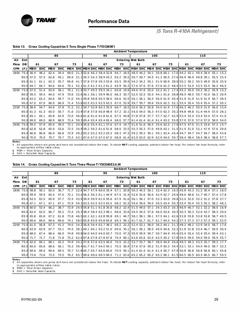
RT-PRC023-EN 29
Performance Data
(5 Tons R-410A Refrigerant)
Table 13. Gross Cooling Capacit ies 5 Tons Single Phase T/YSC060E1
Ambient Temperature
85 95 105 115
Air Ent Entering Wet Bulb
Flow DB 61 67 73 61 67 73 61 67 73 61 67 73
CFM (F) MBH SHC MBH SHC MBH SHC MBH SHC MBH SHC MBH SHC MBH SHC MBH SHC MBH SHC MBH SHC MBH SHC MBH SHC
1800 75.0 56.4 48.2 62.4 34.4 69.0 21.3 52.6 46.3 58.4 32.8 64.7 18.5 48.5 44.2 54.1 30.8 60.1 17.6 44.2 42.1 49.4 28.4 55.1 15.2
80.0 57.5 57.5 62.8 45.1 69.4 31.1 54.3 54.3 58.9 43.2 65.2 29.5 50.7 50.7 54.5 41.2 60.5 27.6 46.9 46.9 49.8 39.1 55.5 25.5
85.0 61.1 61.1 63.3 55.7 69.8 41.7 57.8 57.8 59.3 53.8 65.5 39.9 54.2 54.2 55.1 51.9 60.9 38.0 50.2 50.2 50.5 49.9 55.8 35.9
90.0 64.7 64.7 64.6 64.6 70.1 52.1 61.3 61.3 61.2 61.2 65.9 50.3 57.6 57.6 57.6 57.6 61.3 48.4 53.5 53.5 53.5 53.5 56.2 46.5
2000 75.0 57.5 51.4 63.6 36.1 70.1 21.4 53.7 49.5 59.5 34.1 65.8 19.9 49.6 47.6 55.0 32.2 61.1 17.4 45.2 45.0 50.2 30.2 55.9 15.2
80.0 59.5 59.5 64.0 47.9 70.6 32.6 56.1 56.1 59.9 46.0 66.3 30.7 52.5 52.5 55.5 44.1 61.6 28.8 48.5 48.5 50.7 42.0 56.3 26.9
85.0 63.2 63.2 64.6 59.7 71.0 44.1 59.8 59.8 60.5 58.0 66.6 42.5 56.1 56.1 56.4 56.0 61.9 40.4 51.9 51.9 51.9 51.9 56.7 38.5
90.0 67.0 67.0 66.9 66.9 71.4 55.8 63.5 63.5 63.5 63.5 67.0 53.9 59.7 59.7 59.6 59.6 62.3 52.1 55.4 55.4 55.4 55.4 57.2 50.2
2200 75.0 58.6 54.7 64.6 37.8 71.2 22.1 54.7 52.8 60.3 35.9 66.7 18.5 50.6 50.3 55.8 34.0 61.9 17.6 46.3 46.3 50.9 31.9 56.6 15.6
80.0 61.3 61.3 65.0 50.7 71.6 33.9 57.8 57.8 60.8 48.9 67.2 32.1 54.0 54.0 56.3 47.0 62.3 30.2 49.8 49.8 51.4 44.9 57.0 28.2
85.0 65.1 65.1 65.8 63.9 72.0 46.6 61.6 61.6 61.8 61.6 67.5 44.8 57.8 57.8 57.7 57.7 62.7 42.9 53.4 53.4 53.4 53.4 57.4 41.0
90.0 69.0 69.0 68.9 68.9 72.4 59.3 65.4 65.4 65.4 65.4 68.0 57.7 61.4 61.4 61.4 61.4 63.2 55.8 57.0 57.0 57.0 57.0 58.0 54.0
2400 75.0 59.5 57.9 65.4 39.5 72.1 20.4 55.6 55.4 61.1 37.6 67.4 19.7 51.6 51.6 56.5 35.6 62.5 17.6 47.5 47.5 51.5 33.6 57.2 15.7
80.0 62.8 62.8 65.9 53.6 72.5 34.9 59.2 59.2 61.6 51.8 68.0 33.5 55.3 55.3 57.0 49.8 63.1 31.5 51.0 51.0 52.1 47.9 57.6 29.6
85.0 66.8 66.8 66.9 66.8 72.9 49.2 63.2 63.2 63.2 63.2 68.3 47.3 59.2 59.2 59.1 59.1 63.4 45.4 54.7 54.7 54.7 54.7 58.0 43.6
90.0 70.9 70.9 70.7 70.7 73.3 63.1 67.0 67.0 67.0 67.0 68.8 61.4 63.0 63.0 62.9 62.9 64.0 59.7 58.4 58.4 58.4 58.4 58.8 57.7Notes:
1. A ll capacit ies show n are gross an d have not considered indoor fan h eat. To obtain NET cooling capacity subtrac t indoor fan heat. For indoor fan heat formula, refer to appropriate airf low tab le n otes.
2. MBH = Total Gross Capacity3. SHC = Sens ible Heat Cap ac ity
Table 14. Gross Cooling Capacit ies 5 Tons Three Phase T/YSC060E3,4,W
Ambient Temperature
85 95 105 115
Air Ent Entering Wet Bulb
Flow DB 61 67 73 61 67 73 61 67 73 61 67 73
CFM (F) MBH SHC MBH SHC MBH SHC MBH SHC MBH SHC MBH SHC MBH SHC MBH SHC MBH SHC MBH SHC MBH SHC MBH SHC
1800 75.0 58.8 50.1 65.0 36.7 71.7 22.6 54.7 47.9 60.6 35.4 67.1 20.8 50.3 45.5 56.1 32.4 62.3 19.5 45.8 43.3 51.2 30.4 57.1 18.0
80.0 59.9 59.9 65.4 47.0 72.1 33.4 56.3 56.3 61.1 44.9 67.5 31.4 52.6 52.6 56.6 42.9 62.7 29.6 48.6 48.6 51.7 40.7 57.4 27.8
85.0 63.5 63.5 65.9 57.7 72.5 43.9 59.9 59.9 61.6 55.6 67.9 41.6 56.1 56.1 57.0 53.3 63.0 39.8 52.0 52.0 52.2 51.2 57.8 37.7
90.0 67.1 67.1 67.1 67.1 72.9 54.1 63.5 63.5 63.5 63.5 68.2 52.3 59.6 59.6 59.5 59.5 63.4 50.3 55.4 55.4 55.3 55.3 58.2 48.2
2000 75.0 60.0 53.4 66.2 38.7 72.9 24.5 55.8 51.1 61.8 35.8 68.2 22.4 51.5 49.0 57.1 34.3 63.3 20.3 46.9 46.7 52.1 32.2 58.0 16.9
80.0 62.0 62.0 66.7 50.2 73.4 35.3 58.4 58.4 62.3 48.1 68.6 33.6 54.5 54.5 57.6 46.0 63.6 30.5 50.3 50.3 52.6 43.7 58.3 29.6
85.0 65.8 65.8 67.2 61.8 73.8 46.5 62.1 62.1 62.8 59.8 69.1 44.7 58.1 58.1 58.1 57.5 64.1 42.6 53.8 53.8 53.8 53.8 58.7 40.5
90.0 69.6 69.6 69.6 69.6 74.1 58.0 65.8 65.8 65.8 65.8 69.3 56.1 61.7 61.7 61.7 61.7 64.5 54.2 57.3 57.3 57.3 57.3 59.1 52.0
2200 75.0 61.0 56.8 67.3 41.3 74.0 24.2 56.8 54.4 62.7 38.2 69.2 22.2 52.4 52.1 58.0 36.2 64.1 21.3 48.2 48.2 52.9 34.0 58.7 17.6
80.0 63.9 63.9 67.7 53.1 74.5 38.1 60.1 60.1 63.2 51.0 69.6 35.1 56.1 56.1 58.5 49.0 64.6 32.2 51.8 51.8 53.4 46.7 59.0 30.4
85.0 68.0 67.4 68.4 66.0 74.8 49.8 64.0 64.0 64.0 63.7 70.0 47.3 59.9 59.9 59.7 59.7 64.9 45.4 55.4 55.4 55.4 55.4 59.4 43.1
90.0 71.7 71.7 71.8 71.8 75.2 62.0 67.8 67.8 67.8 67.8 70.4 60.1 63.6 63.6 63.5 63.5 65.2 57.8 59.0 59.0 59.0 59.0 59.9 55.7
2400 75.0 62.0 60.1 68.1 42.2 74.9 24.2 57.8 57.6 63.5 40.0 70.0 22.2 53.7 53.7 58.7 38.0 64.9 20.6 49.3 49.3 53.5 35.7 59.3 17.7
80.0 65.6 65.6 68.6 56.1 75.2 39.4 61.7 61.7 64.0 54.1 70.5 36.4 57.6 57.6 59.2 51.9 65.3 34.4 53.1 53.1 54.0 49.5 59.7 32.2
85.0 69.6 69.6 69.6 69.5 75.7 51.8 65.7 65.7 65.6 65.6 70.9 50.1 61.4 61.4 61.4 61.4 65.7 47.9 56.8 56.8 56.8 56.8 60.1 45.8
90.0 73.6 73.6 73.5 73.5 76.2 65.7 69.6 69.6 69.5 69.5 71.2 63.6 65.2 65.2 65.2 65.2 66.1 61.5 60.5 60.5 60.5 60.5 60.7 59.5
Notes:
1. A ll capacit ies show n are gross an d have not considered indoor fan h eat. To obtain NET cooling capacity subtrac t indoor fan heat. For indoor fan heat formula, refer to appropriate airf low tab le n otes.
2. MBH = Total Gross Capacity3. SHC = Sens ible Heat Cap ac ity

30 RT-PRC023-EN
Performance Data
(3 Tons R-410A Refrigerant)
Table 15. Gross Cooling Capacit ies 3 Tons Single Phase WSC036E1
Ambient Temperature
85 95 105 115
Air Ent Entering Wet Bulb
Flow DB 61 67 73 61 67 73 61 67 73 61 67 73
CFM (F) MBH SHC MBH SHC MBH SHC MBH SHC MBH SHC MBH SHC MBH SHC MBH SHC MBH SHC MBH SHC MBH SHC MBH SHC
1080 75.0 35.7 28.7 39.4 20.8 43.3 12.2 32.9 27.1 36.4 19.2 40.1 10.9 30.0 25.5 33.2 17.7 36.8 9.3 27.0 24.1 29.9 16.1 33.3 7.8
80.0 36.7 35.8 39.9 27.0 43.9 19.0 34.0 34.0 36.9 25.5 40.7 17.6 31.4 31.4 33.8 23.9 37.3 16.1 28.6 28.6 30.5 22.3 33.8 14.6
85.0 38.9 38.9 40.5 33.1 44.3 25.1 36.3 36.3 37.5 31.6 41.1 23.6 33.7 33.7 34.4 30.1 37.7 22.1 30.8 30.8 31.3 28.9 34.2 20.5
90.0 41.3 41.3 41.6 40.4 44.9 31.3 38.7 38.7 38.7 38.6 41.7 29.7 36.0 36.0 36.0 36.0 38.3 28.1 33.1 33.1 33.1 33.1 34.7 26.3
1200 75.0 36.5 30.6 40.2 21.9 44.1 12.5 33.7 29.0 37.0 20.2 40.8 11.0 30.8 27.7 33.8 18.5 37.4 9.5 27.7 26.3 30.5 16.9 33.8 8.0
80.0 37.8 37.8 40.8 28.7 44.6 19.9 35.3 35.3 37.6 27.1 41.4 18.5 32.6 32.6 34.5 25.4 37.9 17.0 29.7 29.7 31.1 23.7 34.3 15.3
85.0 40.4 40.4 41.5 35.5 45.1 26.5 37.7 37.7 38.4 34.2 41.9 25.0 35.0 35.0 35.3 33.0 38.4 23.4 32.0 32.0 32.1 31.7 34.8 22.1
90.0 42.9 42.9 42.9 42.9 45.8 33.1 40.2 40.2 40.1 40.1 42.4 31.5 37.3 37.3 37.3 37.3 39.0 29.9 34.3 34.3 34.3 34.3 35.4 28.5
1320 75.0 37.3 32.5 40.8 22.7 44.7 12.6 34.4 31.2 37.6 21.0 41.4 11.0 31.5 29.9 34.4 19.5 37.9 9.8 28.4 28.3 30.9 18.0 34.2 8.1
80.0 39.1 39.1 41.4 30.2 45.3 20.7 36.4 36.4 38.2 28.5 41.9 19.3 33.6 33.6 35.0 27.0 38.4 17.7 30.7 30.7 31.6 25.4 34.7 15.8
85.0 41.7 41.7 42.3 38.2 45.9 27.9 38.9 38.9 39.3 37.0 42.5 26.3 36.0 36.0 36.2 35.7 39.0 24.8 33.0 33.0 33.0 33.0 35.3 23.3
90.0 44.3 44.3 44.3 44.3 46.5 35.0 41.5 41.5 41.4 41.4 43.2 33.5 38.5 38.5 38.5 38.5 39.7 32.1 35.3 35.3 35.3 35.3 36.1 30.9
1440 75.0 38.0 34.7 41.3 23.6 45.2 12.8 35.1 33.4 38.1 22.0 41.9 11.4 32.1 31.8 34.8 20.6 38.3 9.8 29.0 29.0 31.3 18.9 34.6 8.1
80.0 40.1 40.1 42.0 31.7 45.9 21.6 37.4 37.4 38.9 30.2 42.4 20.0 34.5 34.5 35.5 28.7 38.8 18.1 31.4 31.4 32.1 27.3 35.1 16.5
85.0 42.8 42.8 43.2 41.0 46.5 29.1 40.0 40.0 40.0 39.6 43.1 27.8 37.0 37.0 37.0 37.0 39.5 26.2 33.9 33.9 33.8 33.8 35.7 24.5
90.0 45.5 45.5 45.5 45.5 47.2 37.1 42.6 42.6 42.6 42.6 43.8 35.7 39.5 39.5 39.5 39.5 40.3 34.6 36.3 36.3 36.2 36.2 36.7 33.6Notes:
1. A ll capacit ies show n are gross an d have not considered indoor fan h eat. To obtain NET cooling capacity subtrac t indoor fan heat. For indoor fan heat formula, refer to appropriate airf low tab le n otes.
2. MBH = Total Gross Capacity3. SHC = Sens ible Heat Cap ac ity
Table 16. Gross Cooling Capacit ies 3 Tons Three Phase WSC036E3,4,W
Ambient Temperature
85 95 105 115
Air Ent Entering Wet Bulb
Flow DB 61 67 73 61 67 73 61 67 73 61 67 73
CFM (F) MBH SHC MBH SHC MBH SHC MBH SHC MBH SHC MBH SHC MBH SHC MBH SHC MBH SHC MBH SHC MBH SHC MBH SHC
1080 75.0 36.1 28.9 39.8 21.0 43.6 12.3 33.3 27.4 36.8 19.2 40.4 10.7 30.4 25.8 33.6 17.9 37.1 9.1 27.3 24.4 30.4 16.3 33.6 7.6
80.0 36.9 35.9 40.2 27.0 44.2 19.2 34.2 34.1 37.3 25.5 41.0 17.6 31.6 31.6 34.1 23.9 37.6 15.8 28.8 28.8 30.7 22.3 34.0 14.3
85.0 38.9 38.9 40.7 33.3 44.6 25.0 36.4 36.4 37.8 31.8 41.4 23.8 33.8 33.8 34.6 30.3 38.0 22.2 31.0 31.0 31.4 29.1 34.4 20.3
90.0 41.3 41.3 41.6 40.5 45.1 31.1 38.7 38.7 38.8 38.6 41.9 29.7 36.0 36.0 36.0 36.0 38.4 28.0 33.1 33.1 33.1 33.1 34.8 26.4
1200 75.0 36.9 30.9 40.6 21.8 44.4 12.4 34.1 29.4 37.5 20.3 41.2 10.8 31.1 28.0 34.3 18.8 37.7 9.3 28.0 26.6 30.9 17.1 34.1 7.8
80.0 38.0 37.9 41.1 28.7 45.0 19.7 35.4 35.4 38.0 27.3 41.7 18.3 32.7 32.7 34.7 25.6 38.2 16.8 29.9 29.9 31.4 24.0 34.6 15.0
85.0 40.4 40.4 41.7 35.7 45.5 26.8 37.8 37.8 38.7 34.5 42.1 24.9 35.0 35.0 35.5 33.2 38.6 23.4 32.1 32.1 32.2 31.8 35.0 21.7
90.0 42.9 42.9 42.9 42.9 46.0 33.3 40.3 40.3 40.2 40.2 42.6 31.7 37.3 37.3 37.3 37.3 39.1 30.1 34.3 34.3 34.3 34.3 35.5 28.5
1320 75.0 37.6 32.9 41.3 22.9 45.1 12.5 34.8 31.6 38.1 21.3 41.8 11.0 31.7 30.1 34.8 19.7 38.2 9.4 28.7 28.3 31.4 18.0 34.6 8.0
80.0 39.2 39.2 41.9 30.4 45.7 20.8 36.6 36.6 38.7 28.9 42.3 19.2 33.7 33.7 35.4 27.2 38.7 17.4 30.8 30.8 31.9 25.7 35.0 15.8
85.0 41.8 41.8 42.5 38.5 46.2 27.9 39.0 39.0 39.4 37.2 42.8 26.4 36.1 36.1 36.3 35.8 39.2 24.8 33.1 33.1 33.1 33.0 35.5 23.2
90.0 44.4 44.4 44.3 44.3 46.7 35.2 41.5 41.5 41.5 41.5 43.3 33.7 38.5 38.5 38.5 38.5 39.8 32.3 35.3 35.3 35.3 35.3 36.1 31.1
1440 75.0 38.4 35.1 41.9 23.9 45.7 12.7 35.4 33.7 38.6 22.3 42.3 11.2 32.4 31.9 35.2 20.6 38.7 9.3 29.3 29.2 31.8 19.0 34.9 7.9
80.0 40.3 40.3 42.5 32.1 46.3 21.6 37.6 37.6 39.2 30.4 42.8 20.0 34.6 34.6 35.8 29.0 39.1 18.3 31.6 31.6 32.4 27.6 35.4 16.5
85.0 42.9 42.9 43.3 41.2 46.9 29.3 40.1 40.1 40.3 39.7 43.3 27.8 37.1 37.1 37.1 37.0 39.7 26.4 33.9 33.9 33.9 33.9 35.9 24.6
90.0 45.6 45.6 45.5 45.5 47.5 37.3 42.6 42.6 42.6 42.6 44.0 35.9 39.5 39.5 39.5 39.5 40.4 34.9 36.2 36.2 36.2 36.2 36.6 33.8
Notes:
1. A ll capacit ies show n are gross an d have not considered indoor fan h eat. To obtain NET cooling capacity subtrac t indoor fan heat. For indoor fan heat formula, refer to appropriate airf low tab le n otes.
2. MBH = Total Gross Capacity3. SHC = Sens ible Heat Cap ac ity

RT-PRC023-EN 31
Performance Data
(4 Tons R-410A Refrigerant)
Table 17. Gross Cooling Capacit ies 4 Tons Single Phase WSC048E1
Ambient Temperature
85 95 105 115
Air Ent Entering Wet Bulb
Flow DB 61 67 73 61 67 73 61 67 73 61 67 73
CFM (F) MBH SHC MBH SHC MBH SHC MBH SHC MBH SHC MBH SHC MBH SHC MBH SHC MBH SHC MBH SHC MBH SHC MBH SHC
1440 75.0 46.3 39.0 51.1 28.2 56.2 16.8 43.0 37.1 47.6 26.3 52.4 14.6 39.5 35.1 43.8 24.7 48.4 13.0 35.8 33.0 39.8 22.8 44.3 12.2
80.0 47.1 45.9 51.6 36.7 56.8 25.8 44.0 43.5 48.1 34.8 53.0 24.1 40.7 40.7 44.3 33.0 49.0 22.3 37.5 37.5 40.3 31.2 44.7 20.5
85.0 49.6 49.6 52.2 45.0 57.3 34.3 46.7 46.7 48.7 43.2 53.4 32.1 43.6 43.6 44.9 41.3 49.4 30.7 40.2 40.2 41.0 39.0 45.1 28.8
90.0 52.7 52.7 53.2 51.9 57.8 42.4 49.7 49.7 49.8 49.4 54.0 40.6 46.5 46.5 46.4 46.4 49.8 38.9 43.0 43.0 43.0 43.0 45.5 37.1
1600 75.0 47.3 41.6 52.1 29.5 57.3 17.3 43.9 39.6 48.5 27.9 53.3 14.9 40.4 37.4 44.6 26.1 49.2 12.1 36.6 34.8 40.5 24.1 44.9 13.4
80.0 48.5 48.2 52.7 39.0 57.9 26.9 45.3 45.3 49.0 37.2 53.9 25.2 42.2 42.2 45.2 35.3 49.8 23.4 38.8 38.8 41.1 33.5 45.4 21.7
85.0 51.5 51.5 53.3 48.2 58.3 36.2 48.4 48.4 49.8 46.2 54.4 34.4 45.2 45.2 46.0 43.8 50.3 32.7 41.7 41.7 42.1 41.0 45.8 30.9
90.0 54.7 54.7 54.8 54.6 58.9 45.4 51.5 51.5 51.5 51.5 54.9 43.6 48.2 48.2 48.2 48.2 50.7 41.8 44.6 44.6 44.6 44.6 46.3 40.1
1760 75.0 48.2 43.8 53.0 31.0 58.1 17.0 44.8 41.7 49.2 29.3 54.2 16.4 41.1 39.2 45.3 27.5 50.0 14.1 37.4 36.4 41.1 25.6 45.5 12.6
80.0 49.9 49.9 53.6 41.4 58.7 28.0 46.8 46.8 49.9 39.6 54.7 26.3 43.5 43.5 45.9 37.7 50.5 24.7 40.0 40.0 41.7 35.8 46.0 22.9
85.0 53.2 53.2 54.4 50.9 59.2 38.1 50.0 50.0 50.8 48.5 55.2 36.5 46.6 46.6 47.0 45.7 50.9 34.8 42.9 42.9 43.0 42.8 46.4 33.0
90.0 56.4 56.4 56.4 56.4 59.8 48.4 53.2 53.2 53.1 53.1 55.7 46.5 49.6 49.6 49.6 49.6 51.5 44.9 45.9 45.9 45.9 45.9 47.1 42.8
1920 75.0 49.0 45.9 53.7 32.6 58.9 18.0 45.6 43.4 49.9 30.8 54.8 16.3 41.9 40.7 45.8 28.9 50.5 14.6 38.1 37.8 41.6 27.1 46.0 12.8
80.0 51.2 51.2 54.4 43.6 59.5 29.1 48.0 48.0 50.5 41.9 55.4 27.4 44.6 44.6 46.5 39.9 51.0 25.9 41.0 41.0 42.3 37.8 46.5 23.9
85.0 54.6 54.6 55.4 53.1 60.0 40.2 51.3 51.3 51.7 50.4 55.9 38.6 47.8 47.8 47.9 47.6 51.5 36.9 44.1 44.1 44.0 44.0 47.0 35.0
90.0 58.0 58.0 58.0 58.0 60.6 51.3 54.6 54.6 54.5 54.5 56.6 49.5 51.0 51.0 50.9 50.9 52.2 47.4 47.1 47.1 47.1 47.1 47.8 44.9Notes:
1. A ll capacit ies show n are gross an d have not considered indoor fan h eat. To obtain NET cooling capacity subtrac t indoor fan heat. For indoor fan heat formula, refer to appropriate airf low tab le n otes.
2. MBH = Total Gross Capacity3. SHC = Sens ible Heat Cap ac ity
Table 18. Gross Cooling Capacities 4 Tons Three Phase WSC048E3,4,W
Ambient Temperature
85 95 105 115
Air Ent Entering Wet Bulb
Flow DB 61 67 73 61 67 73 61 67 73 61 67 73
CFM (F) MBH SHC MBH SHC MBH SHC MBH SHC MBH SHC MBH SHC MBH SHC MBH SHC MBH SHC MBH SHC MBH SHC MBH SHC
1440 75.0 47.2 39.3 52.1 28.6 57.4 17.1 43.8 37.4 48.6 26.7 53.6 15.3 40.3 35.5 44.8 24.9 49.6 13.9 36.6 33.5 40.8 23.0 45.4 12.1
80.0 48.1 46.7 52.7 37.0 57.9 25.7 44.8 44.2 49.1 35.2 54.2 24.1 41.5 41.5 45.3 33.4 50.1 22.3 38.3 38.3 41.3 31.4 45.9 20.6
85.0 50.6 50.6 53.3 45.5 58.5 34.0 47.6 47.6 49.7 43.6 54.7 32.5 44.4 44.4 45.9 41.8 50.7 30.7 41.1 41.1 42.0 39.6 46.4 29.0
90.0 53.7 53.7 54.3 52.7 59.0 42.4 50.6 50.6 50.9 50.2 55.2 41.0 47.4 47.4 47.4 47.4 51.2 39.3 44.0 44.0 44.0 44.0 46.9 37.4
1600 75.0 48.3 42.0 53.2 29.9 58.5 18.1 44.8 40.0 49.5 28.2 54.6 16.3 41.2 37.9 45.6 26.1 50.5 14.7 37.4 35.5 41.5 24.4 46.1 12.9
80.0 49.5 49.0 53.8 39.4 59.0 26.3 46.2 46.2 50.1 37.6 55.1 24.4 43.0 43.0 46.3 35.8 51.1 23.6 39.7 39.7 42.1 33.8 46.7 21.6
85.0 52.5 52.5 54.5 48.8 59.6 36.1 49.4 49.4 50.8 46.8 55.7 34.5 46.1 46.1 47.0 44.5 51.6 32.8 42.7 42.7 43.1 41.7 47.2 31.1
90.0 55.8 55.8 55.8 55.4 60.2 45.6 52.5 52.5 52.5 52.5 56.2 44.0 49.2 49.2 49.2 49.2 52.0 42.2 45.7 45.7 45.6 45.6 47.7 40.4
1760 75.0 49.3 44.5 54.1 31.1 59.4 19.0 45.7 42.3 50.3 29.6 55.4 16.5 42.0 39.9 46.3 27.5 51.2 14.5 38.3 37.1 42.2 25.9 46.8 13.0
80.0 50.8 50.8 54.7 41.8 60.0 28.4 47.7 47.7 51.0 39.9 55.9 26.5 44.4 44.4 47.0 38.0 51.8 24.5 40.9 40.9 42.8 36.1 47.3 22.8
85.0 54.2 54.2 55.5 51.7 60.5 38.3 51.0 51.0 51.9 49.3 56.5 36.7 47.6 47.6 48.0 46.5 52.4 35.0 44.0 44.0 44.1 43.7 47.9 33.0
90.0 57.6 57.6 57.5 57.5 61.2 48.7 54.2 54.2 54.2 54.2 57.1 46.9 50.8 50.8 50.8 50.8 52.9 45.3 47.1 47.1 47.1 47.1 48.6 43.5
1920 75.0 50.1 46.6 54.9 32.7 60.2 19.3 46.5 44.2 51.0 31.0 56.1 18.2 42.8 41.4 46.9 29.0 51.9 14.7 39.1 38.6 42.7 27.2 47.3 13.0
80.0 52.2 52.2 55.5 44.1 60.8 29.6 49.0 49.0 51.7 42.3 56.6 27.4 45.6 45.6 47.6 40.3 52.4 25.6 42.0 42.0 43.4 38.4 47.9 24.0
85.0 55.7 55.7 56.5 53.9 61.3 40.3 52.4 52.4 52.8 51.2 57.2 38.9 48.9 48.9 49.1 48.5 53.0 37.1 45.2 45.2 45.2 45.2 48.4 35.3
90.0 59.2 59.2 59.1 59.1 62.0 51.7 55.7 55.7 55.7 55.7 58.0 50.0 52.2 52.2 52.1 52.1 53.7 48.1 48.4 48.4 48.4 48.4 49.3 45.9
Notes:
1. All capac it ies shown are gross and have not cons idered indoor fan heat. To obtain NET coolin g capacity subtrac t in door fan heat. For indoor fan heat formula, refer to appropriate airflow table notes .
2. MBH = Total Gross Capac ity3. SHC = Sensible Heat Capacity
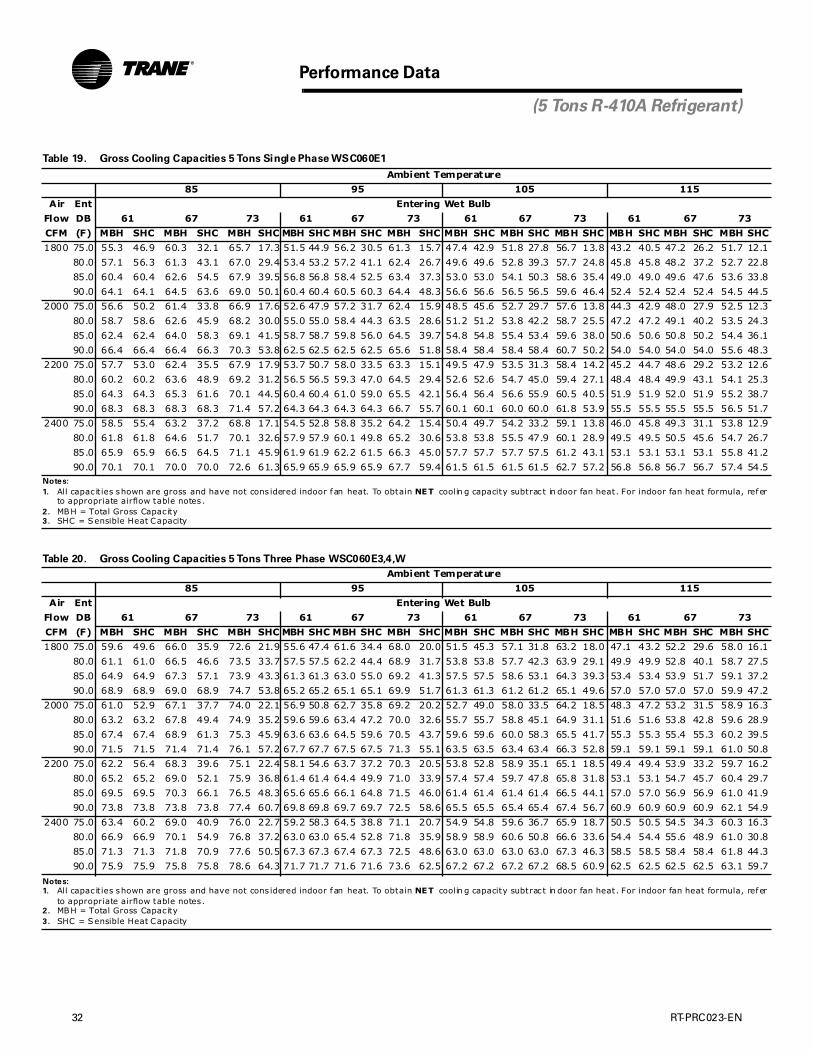
32 RT-PRC023-EN
Performance Data
(5 Tons R-410A Refrigerant)
Table 19. Gross Cooling Capacities 5 Tons Single Phase WSC060E1
Ambient Temperature
85 95 105 115
Air Ent Entering Wet Bulb
Flow DB 61 67 73 61 67 73 61 67 73 61 67 73
CFM (F) MBH SHC MBH SHC MBH SHC MBH SHC MBH SHC MBH SHC MBH SHC MBH SHC MBH SHC MBH SHC MBH SHC MBH SHC
1800 75.0 55.3 46.9 60.3 32.1 65.7 17.3 51.5 44.9 56.2 30.5 61.3 15.7 47.4 42.9 51.8 27.8 56.7 13.8 43.2 40.5 47.2 26.2 51.7 12.1
80.0 57.1 56.3 61.3 43.1 67.0 29.4 53.4 53.2 57.2 41.1 62.4 26.7 49.6 49.6 52.8 39.3 57.7 24.8 45.8 45.8 48.2 37.2 52.7 22.8
85.0 60.4 60.4 62.6 54.5 67.9 39.5 56.8 56.8 58.4 52.5 63.4 37.3 53.0 53.0 54.1 50.3 58.6 35.4 49.0 49.0 49.6 47.6 53.6 33.8
90.0 64.1 64.1 64.5 63.6 69.0 50.1 60.4 60.4 60.5 60.3 64.4 48.3 56.6 56.6 56.5 56.5 59.6 46.4 52.4 52.4 52.4 52.4 54.5 44.5
2000 75.0 56.6 50.2 61.4 33.8 66.9 17.6 52.6 47.9 57.2 31.7 62.4 15.9 48.5 45.6 52.7 29.7 57.6 13.8 44.3 42.9 48.0 27.9 52.5 12.3
80.0 58.7 58.6 62.6 45.9 68.2 30.0 55.0 55.0 58.4 44.3 63.5 28.6 51.2 51.2 53.8 42.2 58.7 25.5 47.2 47.2 49.1 40.2 53.5 24.3
85.0 62.4 62.4 64.0 58.3 69.1 41.5 58.7 58.7 59.8 56.0 64.5 39.7 54.8 54.8 55.4 53.4 59.6 38.0 50.6 50.6 50.8 50.2 54.4 36.1
90.0 66.4 66.4 66.4 66.3 70.3 53.8 62.5 62.5 62.5 62.5 65.6 51.8 58.4 58.4 58.4 58.4 60.7 50.2 54.0 54.0 54.0 54.0 55.6 48.3
2200 75.0 57.7 53.0 62.4 35.5 67.9 17.9 53.7 50.7 58.0 33.5 63.3 15.1 49.5 47.9 53.5 31.3 58.4 14.2 45.2 44.7 48.6 29.2 53.2 12.6
80.0 60.2 60.2 63.6 48.9 69.2 31.2 56.5 56.5 59.3 47.0 64.5 29.4 52.6 52.6 54.7 45.0 59.4 27.1 48.4 48.4 49.9 43.1 54.1 25.3
85.0 64.3 64.3 65.3 61.6 70.1 44.5 60.4 60.4 61.0 59.0 65.5 42.1 56.4 56.4 56.6 55.9 60.5 40.5 51.9 51.9 52.0 51.9 55.2 38.7
90.0 68.3 68.3 68.3 68.3 71.4 57.2 64.3 64.3 64.3 64.3 66.7 55.7 60.1 60.1 60.0 60.0 61.8 53.9 55.5 55.5 55.5 55.5 56.5 51.7
2400 75.0 58.5 55.4 63.2 37.2 68.8 17.1 54.5 52.8 58.8 35.2 64.2 15.4 50.4 49.7 54.2 33.2 59.1 13.8 46.0 45.8 49.3 31.1 53.8 12.9
80.0 61.8 61.8 64.6 51.7 70.1 32.6 57.9 57.9 60.1 49.8 65.2 30.6 53.8 53.8 55.5 47.9 60.1 28.9 49.5 49.5 50.5 45.6 54.7 26.7
85.0 65.9 65.9 66.5 64.5 71.1 45.9 61.9 61.9 62.2 61.5 66.3 45.0 57.7 57.7 57.7 57.5 61.2 43.1 53.1 53.1 53.1 53.1 55.8 41.2
90.0 70.1 70.1 70.0 70.0 72.6 61.3 65.9 65.9 65.9 65.9 67.7 59.4 61.5 61.5 61.5 61.5 62.7 57.2 56.8 56.8 56.7 56.7 57.4 54.5Notes:
1. All capac it ies shown are gross and have not cons idered indoor fan heat. To obtain NET coolin g capacity subtrac t in door fan heat. For indoor fan heat formula, refer to appropriate airflow table notes .
2. MBH = Total Gross Capac ity3. SHC = Sensible Heat Capacity
Table 20. Gross Cooling Capacities 5 Tons Three Phase WSC060E3,4,W
Ambient Temperature
85 95 105 115
Air Ent Entering Wet Bulb
Flow DB 61 67 73 61 67 73 61 67 73 61 67 73
CFM (F) MBH SHC MBH SHC MBH SHC MBH SHC MBH SHC MBH SHC MBH SHC MBH SHC MBH SHC MBH SHC MBH SHC MBH SHC
1800 75.0 59.6 49.6 66.0 35.9 72.6 21.9 55.6 47.4 61.6 34.4 68.0 20.0 51.5 45.3 57.1 31.8 63.2 18.0 47.1 43.2 52.2 29.6 58.0 16.1
80.0 61.1 61.0 66.5 46.6 73.5 33.7 57.5 57.5 62.2 44.4 68.9 31.7 53.8 53.8 57.7 42.3 63.9 29.1 49.9 49.9 52.8 40.1 58.7 27.5
85.0 64.9 64.9 67.3 57.1 73.9 43.3 61.3 61.3 63.0 55.0 69.2 41.3 57.5 57.5 58.6 53.1 64.3 39.3 53.4 53.4 53.9 51.7 59.1 37.2
90.0 68.9 68.9 69.0 68.9 74.7 53.8 65.2 65.2 65.1 65.1 69.9 51.7 61.3 61.3 61.2 61.2 65.1 49.6 57.0 57.0 57.0 57.0 59.9 47.2
2000 75.0 61.0 52.9 67.1 37.7 74.0 22.1 56.9 50.8 62.7 35.8 69.2 20.2 52.7 49.0 58.0 33.5 64.2 18.5 48.3 47.2 53.2 31.5 58.9 16.3
80.0 63.2 63.2 67.8 49.4 74.9 35.2 59.6 59.6 63.4 47.2 70.0 32.6 55.7 55.7 58.8 45.1 64.9 31.1 51.6 51.6 53.8 42.8 59.6 28.9
85.0 67.4 67.4 68.9 61.3 75.3 45.9 63.6 63.6 64.5 59.6 70.5 43.7 59.6 59.6 60.0 58.3 65.5 41.7 55.3 55.3 55.4 55.3 60.2 39.5
90.0 71.5 71.5 71.4 71.4 76.1 57.2 67.7 67.7 67.5 67.5 71.3 55.1 63.5 63.5 63.4 63.4 66.3 52.8 59.1 59.1 59.1 59.1 61.0 50.8
2200 75.0 62.2 56.4 68.3 39.6 75.1 22.4 58.1 54.6 63.7 37.2 70.3 20.5 53.8 52.8 58.9 35.1 65.1 18.5 49.4 49.4 53.9 33.2 59.7 16.2
80.0 65.2 65.2 69.0 52.1 75.9 36.8 61.4 61.4 64.4 49.9 71.0 33.9 57.4 57.4 59.7 47.8 65.8 31.8 53.1 53.1 54.7 45.7 60.4 29.7
85.0 69.5 69.5 70.3 66.1 76.5 48.3 65.6 65.6 66.1 64.8 71.5 46.0 61.4 61.4 61.4 61.4 66.5 44.1 57.0 57.0 56.9 56.9 61.0 41.9
90.0 73.8 73.8 73.8 73.8 77.4 60.7 69.8 69.8 69.7 69.7 72.5 58.6 65.5 65.5 65.4 65.4 67.4 56.7 60.9 60.9 60.9 60.9 62.1 54.9
2400 75.0 63.4 60.2 69.0 40.9 76.0 22.7 59.2 58.3 64.5 38.8 71.1 20.7 54.9 54.8 59.6 36.7 65.9 18.7 50.5 50.5 54.5 34.3 60.3 16.3
80.0 66.9 66.9 70.1 54.9 76.8 37.2 63.0 63.0 65.4 52.8 71.8 35.9 58.9 58.9 60.6 50.8 66.6 33.6 54.4 54.4 55.6 48.9 61.0 30.8
85.0 71.3 71.3 71.8 70.9 77.6 50.5 67.3 67.3 67.4 67.3 72.5 48.6 63.0 63.0 63.0 63.0 67.3 46.3 58.5 58.5 58.4 58.4 61.8 44.3
90.0 75.9 75.9 75.8 75.8 78.6 64.3 71.7 71.7 71.6 71.6 73.6 62.5 67.2 67.2 67.2 67.2 68.5 60.9 62.5 62.5 62.5 62.5 63.1 59.7
Notes:
1. All capac it ies shown are gross and have not cons idered indoor fan heat. To obtain NET coolin g capacity subtrac t in door fan heat. For indoor fan heat formula, refer to appropriate airflow table notes .
2. MBH = Total Gross Capac ity3. SHC = Sensible Heat Capacity
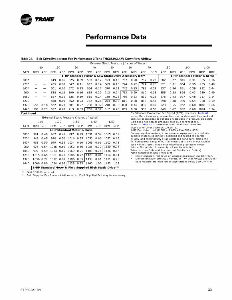
RT-PRC023-EN 33
.
Table 21. Belt Drive Evaporator Fan Performance 3 Tons THC033A3,4,W Downflow Airflow
External Static Pressure (Inches of Water)
.10 .20 .30 .40 .50 .60 .70 .80 .90 1.00
CFM RPM BHP RPM BHP RPM BHP RPM BHP RPM RPM BHP RPM BHP RPM BHP RPM BHP RPM BHP BHP
1-HP Standard Motor & Low Static Drive Accessory Kit(i)
(i) BAYLSDR006 required.
1-HP Standard Motor & Drive
600* — — 449 0.06 525 0.09 593 0.12 653 0.16 707 0.20 757 0.23 802 0.27 845 0.31 885 0.36
720* — — 475 0.08 547 0.11 612 0.14 669 0.18 724 0.22 774 0.26 821 0.31 864 0.35 905 0.40
840* — — 501 0.10 572 0.13 634 0.17 690 0.21 742 0.25 791 0.29 837 0.34 881 0.39 922 0.44
960 — — 528 0.12 599 0.16 658 0.20 713 0.24 763 0.29 810 0.33 855 0.38 898 0.43 939 0.49
1080 — — 557 0.15 625 0.19 685 0.24 738 0.28 786 0.33 832 0.38 876 0.43 917 0.48 957 0.54
1200 — — 588 0.19 652 0.23 712 0.28 764 0.33 811 0.38 856 0.43 898 0.48 939 0.54 978 0.59
1320 552 0.18 622 0.23 681 0.27 738 0.32 790 0.38 838 0.44 882 0.49 923 0.55 962 0.60 1000 0.66
1440 588 0.23 657 0.28 713 0.33 765 0.37 817 0.43 865 0.50 909 0.56 949 0.62 987 0.68 1024 0.74
Continued For S tandard Evaporator Fan Speed (RPM), reference Table 67.Notes: Data includes pressure drop due to s tandard f ilters and w etcoils . No accessories or options are inc luded in pressure drop data.Data does not inc lude pressure drop du e to reheat coil.Refer to Table 72 to determine addit ional static pressuredrop due to other option s/accessories .1-HP Fan Motor Heat (MBH) = 2.829 x Fan BHP+.4024.Fac tory supplied m otors, in com merc ial eq uipm ent, are definitepurpose motors , specifically designed and tested to operate reliably an d continuously at all cataloged conditions. Using thefull horsepower range of ou r fan motors as show n in our tabulardata w ill not result in nuisance tripping or premature motor failure. Our product’s warranty will n ot be af fected.Table inc lu des Dehumidification (Hot Gas Reheat Option).*Un it applications below 960 CFM• E lec tric heaters restric ted on applications b elow 960 CFM/Ton.• Dehu midif ication (Hot Gas Reh eat) or TXV with Frostat and Crank-
case Heaters are required on applications below 9 60 CFM/Ton.
External Static Pressure (Inches of Water)
1.10 1.20 1.30 1.40 1.50
CFM RPM BHP RPM BHP RPM BHP RPM BHP RPM BHP
1-HP Standard Motor & Drive
600* 924 0.40 962 0.45 997 0.49 1031 0.54 1065 0.59
720* 943 0.45 980 0.50 1016 0.55 1050 0.60 1082 0.65
840* 962 0.50 999 0.55 1034 0.60 1068 0.66 1103 0.71
960 978 0.54 1016 0.60 1052 0.66 1086 0.72 1120 0.78
1080 995 0.59 1033 0.65 1069 0.71 1103 0.78 1136 0.84
1200 1015 0.65 1051 0.71 1086 0.77 1120 0.84 1154 0.91
1320 1036 0.72 1072 0.78 1106 0.85 1138 0.91 1171 0.98
1440 1060 0.80 1094 0.86 1128 0.93 1160 1.00 1192 1.07
1-HP Standard Motor & Field Supplied High Static Drive(ii)
(ii ) Field Su pplied Fan Sheave AK41 required. Field Supplied Belt may be necessary.
Performance Data

34 RT-PRC023-EN
Performance Data
Table 22. Belt Drive Evaporator Fan Performance 3 Tons THC033A3,4,W Horizontal Airflow
External Static Pressure (Inches of Water)
.10 .20 .30 .40 .50 .60 .70 .80 .90 1.00
CFM RPM BHP RPM BHP RPM BHP RPM BHP RPM RPM BHP RPM BHP RPM BHP RPM BHP RPM BHP BHP
1-HP Standard Motor & Low Static Drive Accessory Kit(i)
(i) BAYLSDR006 required.
1-HP Standard Motor & Drive
600* — — 493 0.07 567 0.11 628 0.14 683 0.18 737 0.22 786 0.26 832 0.30 876 0.35 918 0.40
720* 427 0.06 523 0.09 599 0.13 662 0.17 716 0.21 766 0.25 811 0.29 856 0.34 899 0.39 940 0.44
840* 460 0.08 555 0.12 631 0.16 694 0.21 750 0.25 799 0.30 844 0.35 886 0.39 925 0.44 965 0.49
960 493 0.10 588 0.15 661 0.19 725 0.24 782 0.29 832 0.35 878 0.40 919 0.46 958 0.51 996 0.56
1080 531 0.13 622 0.18 694 0.24 756 0.29 813 0.34 864 0.40 910 0.46 954 0.52 993 0.59 1031 0.65
1200 570 0.17 654 0.23 727 0.28 787 0.34 843 0.40 895 0.46 942 0.52 986 0.59 1026 0.66 1064 0.73
1320 610 0.22 687 0.28 760 0.34 821 0.40 875 0.46 925 0.53 973 0.59 1017 0.66 1058 0.73 1095 0.81
1440 651 0.27 723 0.33 793 0.40 855 0.47 908 0.53 956 0.60 1003 0.67 1047 0.75 1088 0.82 1127 0.89
1-HP Standard Motor & Field Supplied High Static Drive(ii)
(ii ) Field Su pplied Fan Sheave AK41 required. Field Supplied Belt may be necessary.
Continued For S tandard Evaporator Fan Speed (RPM), reference Table 67.Notes: Data includes pressure drop due to s tandard f ilters and w etcoils . No accessories or options are inc luded in pressure drop data.Data does not inc lude pressure drop du e to reheat coil.Refer to Table 72 to determine addit ional static pressuredrop due to other option s/accessories .1-HP Fan Motor Heat (MBH) = 2.829 x Fan BHP+.4024.Fac tory supplied m otors, in com merc ial eq uipm ent, are definitepurpose motors , specifically designed and tested to operate reliably an d continuously at all cataloged conditions. Using thefull horsepower range of ou r fan motors as show n in our tabulardata w ill not result in nuisance tripping or premature motor failure. Our product’s warranty will n ot be af fected.Table inc lu des Dehumidification (Hot Gas Reheat Option).*Un it applications below 960 CFM• E lec tric heaters restric ted on applications b elow 960 CFM/Ton.• Dehu midif ication (Hot Gas Reh eat) or TXV with Frostat and Crank-
case Heaters are required on applications below 9 60 CFM/Ton.
External Static Pressure (Inches of Water)
1.10 1.20 1.30 1.40 1.50
CFM RPM BHP RPM BHP RPM BHP RPM BHP RPM BHP
1-HP Standard Motor & Drive
600* 958 0.45 996 0.50 1032 0.55 1068 0.60 1102 0.66
720* 978 0.49 1016 0.55 1053 0.61 1087 0.66 1121 0.72
840* 1002 0.55 1039 0.60 1076 0.67 1109 0.72 1143 0.79
960 1032 0.62 1066 0.67 1101 0.73 1133 0.79 1166 0.86
1080 1065 0.70 1099 0.76 1132 0.82 1164 0.89 1194 0.95
1200 1099 0.80 1133 0.86 1166 0.93 1197 0.99 1227 1.06
1320 1132 0.88 1167 0.96 1200 1.04 1230 1.11 1261 1.19
1440 1164 0.97 1199 1.05 1232 1.14 1263 1.22 1294 1.30
1-HP Standard Motor & Field Supplied High Static Drive(iii)
(ii i) Field Su pplied Fan Sheave AK41 required. Field Supplied Belt may be necessary.
(3 Tons R-22 Refrigerant)

RT-PRC023-EN 35
Performance Data
(3 Tons R-22 Refrigerant)
Table 23. Belt Drive Evaporator Fan Performance 3 Tons YHC033A3,4,W*L,M Low & Medium Heat Downflow Airflow
External Static Pressure (Inches of Water)
.10 .20 .30 .40 .50 .60 .70 .80 .90 1.00
CFM RPM BHP RPM BHP RPM BHP RPM BHP RPM RPM BHP RPM BHP RPM BHP RPM BHP RPM BHP BHP
1-HP Standard Motor & Field Supplied Low Static Drive(i)
(i) Field Su pplied Fan Sheave AK69 required. Field Supplied Belt may be necessary.
1-HP Standard Motor & Drive
960 — — 570 0.14 634 0.18 690 0.22 741 0.27 791 0.31 836 0.36 879 0.41 922 0.46 961 0.52
1080 537 0.14 606 0.18 669 0.23 724 0.27 773 0.32 819 0.36 864 0.41 906 0.47 946 0.52 985 0.58
1200 581 0.18 645 0.22 705 0.27 759 0.33 807 0.38 851 0.42 894 0.48 935 0.53 973 0.59 1011 0.65
1320 627 0.23 686 0.28 742 0.33 795 0.39 842 0.44 885 0.50 927 0.55 966 0.61 1003 0.67 1040 0.73
1440 673 0.29 728 0.34 780 0.39 831 0.45 878 0.52 921 0.58 960 0.64 998 0.69 1034 0.76 1070 0.82
Continued For S tandard Evaporator Fan Speed (RPM), reference Table 67.Notes: Data includes pressure drop due to s tandard f ilters and w etcoils . No accessories or options are inc luded in pressure drop data.Data does not inc lude pressure drop du e to reheat coil.Refer to Table 72 to determine addit ional static pressuredrop due to other option s/accessories .1-HP Fan Motor Heat (MBH) = 2.829 x Fan BHP+.4024.Fac tory supplied m otors, in com merc ial eq uipm ent, are definitepurpose motors , specifically designed and tested to operate reliably an d continuously at all cataloged conditions. Using thefull horsepower range of ou r fan motors as show n in our tabulardata w ill not result in nuisance tripping or premature motor failure. Our product’s warranty will n ot be af fected.
External Static Pressure (Inches of Water)
1.10 1.20 1.30 1.40 1.50
CFM RPM BHP RPM BHP RPM BHP RPM BHP RPM BHP
1-HP Standard Motor & Drive
960 1000 0.57 1037 0.63 1072 0.69 1106 0.75 1139 0.81
1080 1022 0.64 1058 0.70 1093 0.76 1127 0.82 1161 0.89
1200 1047 0.71 1083 0.77 1117 0.83 1150 0.90 1183 0.97
1320 1075 0.79 1108 0.85 1141 0.92 1174 0.99 1206 1.06
1440 1104 0.88 1137 0.95 1170 1.02 1201 1.09 1231 1.16
1-HP Standard Motor & Field Supplied High Static Drive(ii)
(ii ) Field Su pplied Fan Sheave AK41 required. Field Supplied Belt may be necessary.
Table 24. Belt Drive Evaporator Fan Performance 3 Tons YHC033A3,4,W*H High Heat Downflow Airflow
External Static Pressure (Inches of Water)
.10 .20 .30 .40 .50 .60 .70 .80 .90 1.00
CFM RPM BHP RPM BHP RPM BHP RPM BHP RPM RPM BHP RPM BHP RPM BHP RPM BHP RPM BHP BHP
1-HP Standard Motor & Field Supplied Low Static Drive(i)
(i) Field Su pplied Fan Sheave AK69 required. Field Supplied Belt may be necessary.
1-HP Standard Motor & Drive
960 503 0.11 578 0.15 641 0.19 696 0.23 747 0.27 796 0.32 841 0.36 884 0.42 926 0.47 966 0.52
1080 548 0.15 616 0.19 678 0.23 731 0.28 780 0.32 826 0.37 870 0.42 912 0.47 952 0.53 991 0.59
1200 593 0.19 657 0.23 716 0.28 768 0.33 815 0.38 859 0.43 901 0.49 942 0.54 980 0.60 1017 0.66
1320 640 0.24 698 0.29 754 0.34 806 0.40 852 0.45 895 0.51 935 0.56 974 0.62 1012 0.68 1048 0.74
1440 688 0.31 742 0.35 794 0.41 844 0.47 890 0.53 931 0.59 970 0.65 1009 0.71 1045 0.77 1080 0.84
Continued For S tandard Evaporator Fan Speed (RPM), reference Table 67.Notes: Data includes pressure drop due to s tandard f ilters and w etcoils . No accessories or options are inc luded in pressure drop data.Data does not inc lude pressure drop du e to reheat coil.Refer to Table 72 to determine addit ional static pressuredrop due to other option s/accessories .1-HP Fan Motor Heat (MBH) = 2.829 x Fan BHP+.4024.Fac tory supplied m otors, in com merc ial eq uipm ent, are definitepurpose motors , specifically designed and tested to operate reliably an d continuously at all cataloged conditions. Using thefull horsepower range of ou r fan motors as show n in our tabulardata w ill not result in nuisance tripping or premature motor failure. Our product’s warranty will n ot be af fected.
External Static Pressure (Inches of Water)
1.10 1.20 1.30 1.40 1.50
CFM RPM BHP RPM BHP RPM BHP RPM BHP RPM BHP
1-HP Standard Motor & Drive
960 1005 0.58 1041 0.64 1076 0.70 1110 0.76 1142 0.82
1080 1029 0.65 1064 0.71 1099 0.77 1133 0.83 1166 0.90
1200 1053 0.72 1089 0.78 1123 0.85 1156 0.91 1189 0.98
1320 1082 0.80 1116 0.87 1150 0.93 1182 1.00 1214 1.07
1440 1113 0.90 1146 0.97 1178 1.04 1209 1.11 1240 1.18
1-HP Standard Motor & Field Supplied High Static Drive(ii)
(ii ) Field Su pplied Fan Sheave AK41 required. Field Supplied Belt may be necessary.

36 RT-PRC023-EN
Performance Data
(3 Tons R-22 Refrigerant)
Table 25. Belt Drive Evaporator Fan Performance 3 Tons YHC033A3,4,W*L,M Low & Medium Heat Horizontal Airflow
External Static Pressure (Inches of Water)
.10 .20 .30 .40 .50 .60 .70 .80 .90 1.00
CFM RPM BHP RPM BHP RPM BHP RPM BHP RPM RPM BHP RPM BHP RPM BHP RPM BHP RPM BHP BHP
1-HP Standard Motor & Field Supplied Low Static Drive(i)
(i) Field Su pplied Fan Sheave AK69 required. Field Supplied Belt may be necessary.
1-HP Standard Motor & Drive
960 552 0.13 631 0.17 699 0.22 759 0.27 811 0.33 858 0.38 902 0.44 943 0.49 980 0.54 1017 0.60
1080 598 0.17 675 0.22 739 0.27 798 0.33 850 0.38 898 0.44 941 0.50 982 0.57 1020 0.63 1056 0.69
1200 645 0.22 720 0.28 781 0.33 837 0.39 889 0.45 937 0.51 981 0.58 1021 0.65 1059 0.72 1095 0.79
1320 693 0.28 766 0.34 825 0.40 879 0.47 929 0.53 976 0.60 1020 0.67 1061 0.74 1099 0.81 1135 0.89
1440 743 0.35 811 0.42 871 0.49 922 0.55 970 0.62 1016 0.69 1059 0.77 1099 0.84 1138 0.92 1174 1.00
1-HP Standard Motor & Field Supplied High Static Drive(ii)
(ii ) Field Su pplied Fan Sheave AK41 required. Field Supplied Belt may be necessary.
Continued For S tandard Evaporator Fan Speed (RPM), reference Table 67.Notes: Data includes pressure drop due to s tandard f ilters and w etcoils . No accessories or options are inc luded in pressure drop data.Data does not inc lude pressure drop du e to reheat coil.Refer to Table 72 to determine addit ional static pressuredrop due to other option s/accessories .1-HP Fan Motor Heat (MBH) = 2.829 x Fan BHP+.4024.Fac tory supplied m otors, in com merc ial eq uipm ent, are definitepurpose motors , specifically designed and tested to operate reliably an d continuously at all cataloged conditions. Using thefull horsepower range of ou r fan motors as show n in our tabulardata w ill not result in nuisance tripping or premature motor failure. Our product’s warranty will n ot be af fected.
External Static Pressure (Inches of Water)
1.10 1.20 1.30 1.40 1.50
CFM RPM BHP RPM BHP RPM BHP RPM BHP RPM BHP
1-HP Standard Motor & Drive
960 1052 0.65 1086 0.71 1120 0.77 1152 0.83 1185 0.90
1080 1090 0.75 1123 0.81 1154 0.87 1185 0.93 1215 0.99
1200 1130 0.86 1162 0.92 1193 0.99 1224 1.05 1253 1.12
1320 1169 0.96 1203 1.04 1233 1.12 1263 1.19 1292 1.26
1440 1208 1.08 1241 1.16 1273 1.25 1303 1.33 1332 1.41
1-HP Standard Motor & Field Supplied High Static Drive(iii)
(ii i) Field Su pplied Fan Sheave AK41 required. Field Supplied Belt may be necessary.
Table 26. Belt Drive Evaporator Fan Performance 3 Tons YHC033A3,4,W*H High Heat Horizontal Airflow
External Static Pressure (Inches of Water)
.10 .20 .30 .40 .50 .60 .70 .80 .90 1.00
CFM RPM BHP RPM BHP RPM BHP RPM BHP RPM RPM BHP RPM BHP RPM BHP RPM BHP RPM BHP BHP
1-HP Standard Motor & Field Supplied Low Static Drive(i)
(i) Field Su pplied Fan Sheave AK69 required. Field Supplied Belt may be necessary.
1-HP Standard Motor & Drive
960 563 0.13 639 0.18 707 0.23 766 0.28 817 0.33 864 0.39 908 0.44 947 0.49 985 0.55 1020 0.60
1080 611 0.18 685 0.23 748 0.28 806 0.34 858 0.39 905 0.45 947 0.51 988 0.58 1026 0.64 1061 0.70
1200 660 0.23 732 0.29 792 0.34 847 0.40 899 0.46 945 0.53 989 0.59 1029 0.66 1066 0.73 1102 0.80
1320 711 0.29 781 0.36 838 0.42 890 0.48 940 0.55 986 0.61 1029 0.68 1070 0.76 1106 0.83 1142 0.90
1440 762 0.37 829 0.44 885 0.51 935 0.57 983 0.64 1028 0.71 1070 0.79 1111 0.86 1148 0.94 1183 1.02
1-HP Standard Motor & Field Supplied High Static Drive(ii)
(ii ) Field Su pplied Fan Sheave AK41 required. Field Supplied Belt may be necessary.
Continued For S tandard Evaporator Fan Speed (RPM), reference Table 67.Notes: Data includes pressure drop due to s tandard f ilters and w etcoils . No accessories or options are inc luded in pressure drop data.Data does not inc lude pressure drop du e to reheat coil.Refer to Table 72 to determine addit ional static pressuredrop due to other option s/accessories .1-HP Fan Motor Heat (MBH) = 2.829 x Fan BHP+.4024.Fac tory supplied m otors, in com merc ial eq uipm ent, are definitepurpose motors , specifically designed and tested to operate reliably an d continuously at all cataloged conditions. Using thefull horsepower range of ou r fan motors as show n in our tabulardata w ill not result in nuisance tripping or premature motor failure. Our product’s warranty will n ot be af fected.
External Static Pressure (Inches of Water)
1.10 1.20 1.30 1.40 1.50
CFM RPM BHP RPM BHP RPM BHP RPM BHP RPM BHP
1-HP Standard Motor & Drive
960 1056 0.66 1090 0.71 1123 0.78 1156 0.84 1188 0.90
1080 1096 0.76 1128 0.82 1159 0.88 1190 0.94 1220 1.00
1200 1135 0.87 1168 0.93 1199 1.00 1229 1.07 1259 1.13
1320 1177 0.98 1209 1.06 1241 1.14 1270 1.21 1299 1.28
1440 1217 1.10 1250 1.18 1281 1.27 1311 1.35 1339 1.43
1-HP Standard Motor & Field Supplied High Static Drive(iii)
(ii i) Field Su pplied Fan Sheave AK41 required. Field Supplied Belt may be necessary.

RT-PRC023-EN 37
Performance Data
(4 Tons R-22 Refrigerant)
Table 27. Belt Drive Evaporator Fan Performance 4 Tons THC043A3,4,W Downflow Airflow
External Static Pressure (Inches of Water)
.10 .20 .30 .40 .50 .60 .70 .80 .90 1.00
CFM RPM BHP RPM BHP RPM BHP RPM BHP RPM RPM BHP RPM BHP RPM BHP RPM BHP RPM BHP BHP
1-HP Standard Motor & Low Static Drive Accessory Kit(i)
(i) BAYLSDR007A required.
1-HP Standard Motor & Drive
800* — — 501 0.09 571 0.13 633 0.16 690 0.20 742 0.25 792 0.29 838 0.34 882 0.39 923 0.44
960* 459 0.09 539 0.13 609 0.17 668 0.21 721 0.25 771 0.29 819 0.34 864 0.39 906 0.44 947 0.50
1120* 509 0.13 580 0.17 646 0.21 706 0.26 758 0.31 805 0.36 850 0.41 893 0.46 934 0.51 973 0.57
1280 559 0.18 626 0.23 686 0.27 744 0.32 796 0.38 843 0.43 885 0.49 927 0.54 967 0.60 1005 0.66
1440 609 0.24 674 0.30 730 0.34 783 0.39 834 0.45 882 0.52 924 0.58 964 0.64 1002 0.70 1038 0.76
1600 661 0.32 724 0.38 776 0.44 825 0.49 872 0.54 919 0.61 962 0.68 1002 0.75 1039 0.82 1076 0.89
1760 716 0.42 775 0.48 825 0.54 870 0.60 915 0.66 958 0.72 999 0.79 1040 0.87 1078 0.95 1113 1.03
1920 771 0.53 825 0.59 875 0.66 918 0.73 959 0.79 1000 0.86 1039 0.92 1078 1.00 1116 1.09 1151 1.17
Continued For S tandard Evaporator Fan Speed (RPM), reference Table 67.Notes: Data includes pressure drop due to s tandard f ilters and w etcoils . No accessories or options are inc luded in pressure drop data.Data does not inc lude pressure drop du e to reheat coil.Refer to Table 72 to determine addit ional static pressuredrop due to other option s/accessories .1-HP Fan Motor Heat (MBH) = 2.829 x Fan BHP+.4024.Fac tory supplied m otors, in com merc ial eq uipm ent, are definitepurpose motors , specifically designed and tested to operate reliably an d continuously at all cataloged conditions. Using thefull horsepower range of ou r fan motors as show n in our tabulardata w ill not result in nuisance tripping or premature motor failure. Our product’s warranty will n ot be af fected.Table inc lu des Dehumidification (Hot Gas Reheat Option).*Un it applications below 128 0 CFM• E lec tric heaters restric ted on applications b elow 1280 CFM/Ton.• Dehu midif ication (Hot Gas Reh eat) or TXV with Frostat and Crank-
case Heaters are required on applications below 1 280 CFM/Ton.
External Static Pressure (Inches of Water)
1.10 1.20 1.30 1.40 1.50
CFM RPM BHP RPM BHP RPM BHP RPM BHP RPM BHP
1-HP Standard Motor & Drive
800* 963 0.49 999 0.54 1034 0.59 1068 0.65 1101 0.70
960* 986 0.55 1023 0.61 1060 0.67 1095 0.73 1127 0.79
1120* 1012 0.63 1048 0.69 1084 0.75 1118 0.81 1151 0.88
1280 1041 0.72 1076 0.78 1110 0.84 1143 0.91 1176 0.98
1440 1074 0.83 1108 0.89 1141 0.96 1174 1.03 1205 1.10
1600 1109 0.95 1142 1.02 1175 1.09 1207 1.17 1236 1.24
1760 1147 1.10 1179 1.17 1211 1.25 1241 1.32 — —
1920 1186 1.26 1218 1.34 1249 1.42 — — — —
Table 28. Belt Drive Evaporator Fan Performance 4 Tons THC043A3,4,W Horizontal Airflow
External Static Pressure (Inches of Water)
.10 .20 .30 .40 .50 .60 .70 .80 .90 1.00
CFM RPM BHP RPM BHP RPM BHP RPM BHP RPM RPM BHP RPM BHP RPM BHP RPM BHP RPM BHP BHP
1-HP Standard Motor & Low Static Drive Accessory Kit(i)
(i) BAYLSDR007A required.
1-HP Standard Motor & Drive
800* 461 0.08 553 0.11 629 0.16 692 0.20 745 0.25 794 0.29 838 0.34 881 0.38 922 0.43 962 0.48
960* 509 0.11 600 0.16 672 0.20 736 0.25 791 0.30 841 0.36 887 0.42 927 0.47 966 0.52 1004 0.58
1120* 561 0.16 649 0.21 719 0.26 779 0.32 836 0.37 886 0.43 932 0.50 975 0.56 1014 0.63 1052 0.69
1280 617 0.21 696 0.27 767 0.34 826 0.40 879 0.46 930 0.52 976 0.59 1020 0.66 1060 0.73 1098 0.80
1440 674 0.29 745 0.35 815 0.42 874 0.49 925 0.56 974 0.63 1020 0.70 1064 0.77 1104 0.85 1142 0.92
1600 733 0.38 799 0.45 862 0.53 922 0.60 975 0.68 1020 0.75 1065 0.83 1107 0.91 1147 0.99 1186 1.07
1760 793 0.49 854 0.56 911 0.65 969 0.73 1023 0.82 1069 0.90 1112 0.98 1152 1.07 1191 1.15 1230 1.24
1920 853 0.62 911 0.70 964 0.79 1018 0.88 1069 0.97 1118 1.06 1161 1.15 1201 1.25 1239 1.34 1275 1.43
1-HP Standard Motor & Field Supplied High Static Drive(ii)
(ii ) Field Su pplied Fan Sheave AK41 required. Field Supplied Belt may be necessary.
Continued For S tandard Evaporator Fan Speed (RPM), reference Table 67.Notes: Data includes pressure drop due to s tandard f ilters and w etcoils . No accessories or options are inc luded in pressure drop data.Data does not inc lude pressure drop du e to reheat coil.Refer to Table 72 to determine addit ional static pressuredrop due to other option s/accessories .1-HP Fan Motor Heat (MBH) = 2.829 x Fan BHP+.4024.Fac tory supplied m otors, in com merc ial eq uipm ent, are definitepurpose motors , specifically designed and tested to operate reliably an d continuously at all cataloged conditions. Using thefull horsepower range of ou r fan motors as show n in our tabulardata w ill not result in nuisance tripping or premature motor failure. Our product’s warranty will n ot be af fected.Table inc lu des Dehumidification (Hot Gas Reheat Option).*Un it applications below 128 0 CFM• E lec tric heaters restric ted on applications b elow 1280 CFM/Ton.• Dehu midif ication (Hot Gas Reh eat) or TXV with Frostat and Crank-
case Heaters are required on applications below 1 280 CFM/Ton.
External Static Pressure (Inches of Water)
1.10 1.20 1.30 1.40 1.50
CFM RPM BHP RPM BHP RPM BHP RPM BHP RPM BHP
1-HP Standard Motor
800* 1001 0.54 1038 0.60 1072 0.65 1108 0.71 1142 0.78
960* 1040 0.63 1073 0.68 1108 0.75 1141 0.81 1175 0.88
1120* 1087 0.75 1119 0.81 1152 0.88 1183 0.94 1213 1.00
1280 1132 0.88 1167 0.95 1199 1.03 1231 1.10 1260 1.17
1440 1179 1.01 1213 1.09 1245 1.17 1277 1.26 1307 1.34
1600 1223 1.15 1258 1.24 1291 1.33 1322 1.42 — —
1760 1267 1.33 1301 1.42 — — — — — —
1920 — — — — — — — — — —
1-HP Standard Motor & Field Supplied High Static Drive(iii)
(ii i) Field Su pplied Fan Sheave AK41 required. Field Supplied Belt may be necessary.

38 RT-PRC023-EN
Performance Data
(4 Tons R-22 Refrigerant)
Table 29. Belt Drive Evaporator Fan Performance 4 Tons YHC043A3,4,W*L,M Low & Medium Heat Downflow Airflow
External Static Pressure (Inches of Water)
.10 .20 .30 .40 .50 .60 .70 .80 .90 1.00
CFM RPM BHP RPM BHP RPM BHP RPM BHP RPM RPM BHP RPM BHP RPM BHP RPM BHP RPM BHP BHP
1-HP Standard Motor & Low Static Drive Accessory Kit(i)
(i) Field Su pplied Fan Sheave AK61 required. Field Supplied Belt may be necessary.
1-HP Standard Motor & Drive
1280 614 0.22 675 0.26 733 0.31 787 0.37 834 0.42 878 0.48 919 0.53 959 0.59 997 0.65 1034 0.71
1440 676 0.30 731 0.34 784 0.39 835 0.46 883 0.52 925 0.58 965 0.64 1003 0.70 1039 0.76 1075 0.83
1600 739 0.40 789 0.45 838 0.50 885 0.56 931 0.63 973 0.70 1012 0.77 1049 0.84 1085 0.91 1118 0.97
1760 803 0.51 850 0.57 894 0.63 938 0.69 981 0.76 1021 0.83 1061 0.92 1097 0.99 1131 1.07 1164 1.14
1920 867 0.65 911 0.72 952 0.78 993 0.84 1033 0.91 1071 0.99 1110 1.07 1145 1.16 1180 1.25 1213 1.33
Continued For S tandard Evaporator Fan Speed (RPM), reference Table 67.Notes: Data includes pressure drop due to s tandard f ilters and w etcoils . No accessories or options are inc luded in pressure drop data.Data does not inc lude pressure drop du e to reheat coil.Refer to Table 72 to determine addit ional static pressuredrop due to other option s/accessories .1-HP Fan Motor Heat (MBH) = 2.829 x Fan BHP+.4024.Fac tory supplied m otors, in com merc ial eq uipm ent, are definitepurpose motors , specifically designed and tested to operate reliably an d continuously at all cataloged conditions. Using thefull horsepower range of ou r fan motors as show n in our tabulardata w ill not result in nuisance tripping or premature motor failure. Our product’s warranty will n ot be af fected.
External Static Pressure (Inches of Water)
1.10 1.20 1.30 1.40 1.50
CFM RPM BHP RPM BHP RPM BHP RPM BHP RPM BHP
1-HP Standard Motor & Drive
1280 1069 0.77 1104 0.83 1138 0.90 1170 0.97 1203 1.04
1440 1109 0.89 1141 0.96 1175 1.03 1205 1.10 1236 1.17
1600 1151 1.04 1183 1.11 1215 1.19 1246 1.26 1275 1.33
1760 1197 1.21 1227 1.29 1258 1.36 1287 1.44 — —
1920 1243 1.41 1274 1.49 — — — — — —
1-HP Standard Motor & Field Supplied High Static Drive(ii)
(ii ) Field Su pplied Fan Sheave AK41 required. Field Supplied Belt may be necessary.
Table 30. Belt Drive Evaporator Fan Performance 4 Tons YHC043A3,4,W*H High Heat Downflow Airflow
External Static Pressure (Inches of Water)
.10 .20 .30 .40 .50 .60 .70 .80 .90 1.00
CFM RPM BHP RPM BHP RPM BHP RPM BHP RPM RPM BHP RPM BHP RPM BHP RPM BHP RPM BHP BHP
1-HP Standard Motor & Field Supplied Low Static Drive(i)
(i) Field Su pplied Fan Sheave AK61 required. Field Supplied Belt may be necessary.
1-HP Standard Motor & Drive
1280 627 0.23 688 0.27 745 0.32 797 0.38 844 0.43 887 0.49 928 0.54 967 0.60 1006 0.66 1042 0.72
1440 691 0.31 746 0.36 798 0.41 848 0.47 894 0.54 936 0.60 975 0.66 1012 0.72 1049 0.78 1085 0.85
1600 756 0.41 806 0.47 854 0.52 901 0.58 945 0.66 987 0.73 1025 0.79 1061 0.86 1096 0.93 1129 1.00
1760 822 0.54 868 0.60 912 0.65 955 0.71 997 0.79 1038 0.87 1076 0.95 1111 1.02 1145 1.10 1178 1.17
1920 889 0.69 931 0.75 972 0.81 1012 0.88 1051 0.95 1090 1.03 1127 1.11 1162 1.20 1196 1.29 1228 1.37
Continued For S tandard Evaporator Fan Speed (RPM), reference Table 67.Notes: Data includes pressure drop due to s tandard f ilters and w etcoils . No accessories or options are inc luded in pressure drop data.Data does not inc lude pressure drop du e to reheat coil.Refer to Table 72 to determine addit ional static pressuredrop due to other option s/accessories .1-HP Fan Motor Heat (MBH) = 2.829 x Fan BHP+.4024.Fac tory supplied m otors, in com merc ial eq uipm ent, are definitepurpose motors , specifically designed and tested to operate reliably an d continuously at all cataloged conditions. Using thefull horsepower range of ou r fan motors as show n in our tabulardata w ill not result in nuisance tripping or premature motor failure. Our product’s warranty will n ot be af fected.
External Static Pressure (Inches of Water)
1.10 1.20 1.30 1.40 1.50
CFM RPM BHP RPM BHP RPM BHP RPM BHP RPM BHP
1-HP Standard Motor & Drive
1280 1077 0.78 1112 0.85 1145 0.91 1178 0.98 1210 1.05
1440 1118 0.91 1150 0.98 1183 1.05 1214 1.12 1244 1.19
1600 1162 1.06 1193 1.13 1225 1.21 1255 1.28 1285 1.36
1760 1208 1.24 1239 1.32 1268 1.39 1297 1.47 — —
1920 1258 1.45 — — — — — — — —
1-HP Standard Motor & Field Supplied High Static Drive(ii)
(ii ) Field Su pplied Fan Sheave AK41 required. Field Supplied Belt may be necessary.

RT-PRC023-EN 39
Performance Data
(4 Tons R-22 Refrigerant)
Table 31. Belt Drive Evaporator Fan Performance 4 Tons YHC043A3,4,W*L,M Low & Medium Heat Horizontal Airflow
External Static Pressure (Inches of Water)
.10 .20 .30 .40 .50 .60 .70 .80 .90 1.00
CFM RPM BHP RPM BHP RPM BHP RPM BHP RPM RPM BHP RPM BHP RPM BHP RPM BHP RPM BHP BHP
1-HP Standard Motor & Field Supplied Low Static Drive(i)
(i) Field Su pplied Fan Sheave AK61 required. Field Supplied Belt may be necessary.
1-HP Standard Motor & Drive
1280 681 0.26 755 0.32 816 0.38 870 0.45 921 0.51 968 0.58 1013 0.65 1053 0.72 1091 0.79 1127 0.86
1440 748 0.36 817 0.43 876 0.49 927 0.56 976 0.63 1022 0.70 1065 0.78 1106 0.85 1144 0.93 1180 1.01
1600 816 0.47 879 0.55 937 0.62 987 0.70 1033 0.78 1076 0.85 1119 0.93 1158 1.01 1197 1.10 1233 1.18
1760 885 0.61 943 0.69 999 0.78 1049 0.86 1093 0.94 1135 1.03 1174 1.11 1213 1.20 1250 1.29 1286 1.38
1920 956 0.77 1009 0.86 1062 0.96 1110 1.05 1154 1.14 1195 1.23 1232 1.32 1269 1.41 1304 1.50 — —
1-HP Standard Motor & Field Supplied High Static Drive(ii)
(ii ) Field Su pplied Fan Sheave AK41 required. Field Supplied Belt may be necessary.
Continued For S tandard Evaporator Fan Speed (RPM), reference Table 67.Notes: Data includes pressure drop due to s tandard f ilters and w etcoils . No accessories or options are inc luded in pressure drop data.Data does not inc lude pressure drop du e to reheat coil.Refer to Table 72 to determine addit ional static pressuredrop due to other option s/accessories .1-HP Fan Motor Heat (MBH) = 2.829 x Fan BHP+.4024.Fac tory supplied m otors, in com merc ial eq uipm ent, are definitepurpose motors , specifically designed and tested to operate reliably an d continuously at all cataloged conditions. Using thefull horsepower range of ou r fan motors as show n in our tabulardata w ill not result in nuisance tripping or premature motor failure. Our product’s warranty will n ot be af fected.
External Static Pressure (Inches of Water)
1.10 1.20 1.30 1.40 1.50
CFM RPM BHP RPM BHP RPM BHP RPM BHP RPM BHP
1-HP Standard Motor & Drive
1280 1162 0.94 1193 1.01 1225 1.09 1255 1.16 1284 1.23
1440 1214 1.09 1247 1.18 1278 1.26 1309 1.35 1337 1.43
1600 1268 1.27 1300 1.35 1332 1.45 — — — —
1760 1320 1.47 — — — — — — — —
1920 — — — — — — — — — —
1-HP Standard Motor & Field Supplied High Static Drive(iii)
(ii i) Field Su pplied Fan Sheave AK41 required. Field Supplied Belt may be necessary.
Table 32. Belt Drive Evaporator Fan Performance 4 Tons YHC043A3,4,W*H High Heat Horizontal Airflow
External Static Pressure (Inches of Water)
.10 .20 .30 .40 .50 .60 .70 .80 .90 1.00
CFM RPM BHP RPM BHP RPM BHP RPM BHP RPM RPM BHP RPM BHP RPM BHP RPM BHP RPM BHP BHP
1-HP Standard Motor & Field Supplied Low Static Drive(i)
(i) Field Su pplied Fan Sheave AK61 required. Field Supplied Belt may be necessary.
1-HP Standard Motor & Drive
1280 698 0.28 769 0.34 828 0.40 881 0.46 932 0.52 978 0.59 1021 0.66 1061 0.73 1099 0.81 1134 0.88
1440 767 0.37 834 0.44 890 0.51 941 0.58 988 0.65 1034 0.72 1077 0.80 1116 0.87 1153 0.95 1190 1.03
1600 837 0.50 899 0.57 955 0.65 1003 0.72 1048 0.80 1091 0.88 1132 0.96 1171 1.04 1209 1.12 1245 1.21
1760 908 0.64 966 0.73 1020 0.81 1067 0.89 1110 0.98 1151 1.06 1190 1.15 1228 1.23 1264 1.32 1300 1.41
1920 981 0.82 1035 0.91 1085 1.00 1133 1.09 1174 1.18 1213 1.27 1250 1.37 1286 1.46 — — — —
1-HP Standard Motor & Field Supplied High Static Drive(ii)
(ii ) Field Su pplied Fan Sheave AK41 required. Field Supplied Belt may be necessary.
Continued For S tandard Evaporator Fan Speed (RPM), reference Table 67.Notes: Data includes pressure drop due to s tandard f ilters and w etcoils . No accessories or options are inc luded in pressure drop data.Data does not inc lude pressure drop du e to reheat coil.Refer to Table 72 to determine addit ional static pressuredrop due to other option s/accessories .1-HP Fan Motor Heat (MBH) = 2.829 x Fan BHP+.4024.Fac tory supplied m otors, in com merc ial eq uipm ent, are definitepurpose motors , specifically designed and tested to operate reliably an d continuously at all cataloged conditions. Using thefull horsepower range of ou r fan motors as show n in our tabulardata w ill not result in nuisance tripping or premature motor failure. Our product’s warranty will n ot be af fected.
External Static Pressure (Inches of Water)
1.10 1.20 1.30 1.40 1.50
CFM RPM BHP RPM BHP RPM BHP RPM BHP RPM BHP
1-HP Standard Motor & Drive
1280 1169 0.96 1201 1.03 1231 1.10 1262 1.17 1290 1.24
1440 1222 1.11 1256 1.20 1286 1.28 1317 1.37 1346 1.45
1600 1278 1.29 1311 1.38 1342 1.48 — — — —
1760 — — — — — — — — — —
1920 — — — — — — — — — —
1-HP Standard Motor & Field Supplied High Static Drive(iii)
(ii i) Field Su pplied Fan Sheave AK41 required. Field Supplied Belt may be necessary.
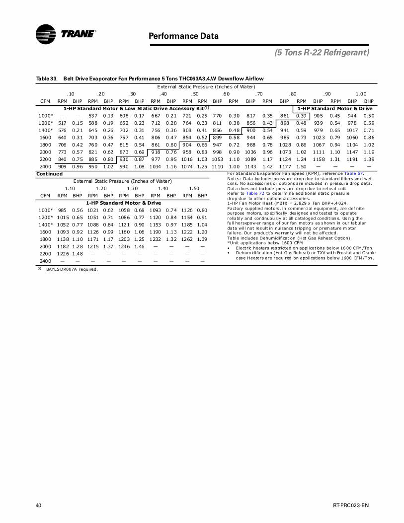
40 RT-PRC023-EN
Performance Data
(5 Tons R-22 Refrigerant)
Table 33. Belt Drive Evaporator Fan Performance 5 Tons THC063A3,4,W Downflow Airflow
External Static Pressure (Inches of Water)
.10 .20 .30 .40 .50 .60 .70 .80 .90 1.00
CFM RPM BHP RPM BHP RPM BHP RPM BHP RPM RPM BHP RPM BHP RPM BHP RPM BHP RPM BHP BHP
1-HP Standard Motor & Low Static Drive Accessory Kit(i)
(i) BAYLSDR007A required.
1-HP Standard Motor & Drive
1000* — — 537 0.13 608 0.17 667 0.21 721 0.25 770 0.30 817 0.35 861 0.39 905 0.45 944 0.50
1200* 517 0.15 588 0.19 652 0.23 712 0.28 764 0.33 811 0.38 856 0.43 898 0.48 939 0.54 978 0.59
1400* 576 0.21 645 0.26 702 0.31 756 0.36 808 0.41 856 0.48 900 0.54 941 0.59 979 0.65 1017 0.71
1600 640 0.31 703 0.36 757 0.41 806 0.47 854 0.52 899 0.58 944 0.65 985 0.73 1023 0.79 1060 0.86
1800 706 0.42 760 0.47 815 0.54 861 0.60 904 0.66 947 0.72 988 0.78 1028 0.86 1067 0.94 1104 1.02
2000 773 0.57 821 0.62 873 0.69 918 0.76 958 0.83 998 0.90 1036 0.96 1073 1.02 1111 1.10 1147 1.19
2200 840 0.75 885 0.80 930 0.87 977 0.95 1016 1.03 1053 1.10 1089 1.17 1124 1.24 1158 1.31 1191 1.39
2400 909 0.96 950 1.02 990 1.08 1034 1.16 1074 1.25 1110 1.00 1143 1.42 1177 1.50 — — — —
Continued For Standard Evaporator Fan Speed (RPM), reference Table 67.Notes: Data inc ludes pressure drop due to standard filters an d wetcoils. No accessories or options are included in pressure drop data.Data does not include pressure drop due to reheat coil.Refer to Table 72 to determine additional s tatic pressu redrop due to other options/accessories.1-HP Fan Motor Heat (MBH) = 2.829 x Fan BHP+.4 024.Factory supplied motors , in commercial equipment, are def initepurpose motors, sp ec ifically des igned and tested to operate reliably and continuou sly at all cataloged condit ion s. Us in g th efu ll horsepow er range of our fan motors as shown in our tabulardata will not result in nuisance tripping or prem ature m otor failure. Our produc t’s warran ty will not be affected.Table includes Dehumidification (Hot Gas Reheat Option).*Unit applications below 1600 CFM• Electric heaters res tricted on applications below 16 00 CFM/Ton.• Dehum idification (Hot Gas Reheat) or TXV w ith Fros tat and Crank-
case Heaters are required on applications below 1600 CFM/Ton .
External Static Pressure (Inches of Water)
1.10 1.20 1.30 1.40 1.50
CFM RPM BHP RPM BHP RPM BHP RPM BHP RPM BHP
1-HP Standard Motor & Drive
1000* 985 0.56 1021 0.62 1058 0.68 1093 0.74 1126 0.80
1200* 1015 0.65 1051 0.71 1086 0.77 1120 0.84 1154 0.91
1400* 1052 0.77 1088 0.84 1121 0.90 1153 0.97 1185 1.04
1600 1093 0.92 1126 0.99 1160 1.06 1190 1.13 1222 1.20
1800 1138 1.10 1171 1.17 1203 1.25 1232 1.32 1262 1.39
2000 1182 1.28 1215 1.37 1246 1.46 — — — —
2200 1226 1.48 — — — — — — — —
2400 — — — — — — — — — —

RT-PRC023-EN 41
Performance Data
(5 Tons R-22 Refrigerant)
Table 34. Belt Drive Evaporator Fan Performance 5 Tons THC063A3,4,W Horizontal Airflow
External Static Pressure (Inches of Water)
.10 .20 .30 .40 .50 .60 .70 .80 .90 1.00
CFM RPM BHP RPM BHP RPM BHP RPM BHP RPM RPM BHP RPM BHP RPM BHP RPM BHP RPM BHP BHP
1-HP Standard Motor & Low Static Drive Accessory Kit(i)
(i) BAYLSDR008A required.
1-HP Standard Motor & Drive
1000* 507 0.11 599 0.16 671 0.21 735 0.26 792 0.31 843 0.37 889 0.42 931 0.48 971 0.54 1007 0.59
1200* 570 0.17 654 0.23 727 0.28 787 0.34 843 0.40 895 0.46 942 0.52 986 0.59 1026 0.66 1064 0.73
1400* 638 0.25 711 0.31 782 0.38 844 0.44 896 0.51 946 0.58 993 0.65 1037 0.72 1078 0.79 1117 0.86
1600 707 0.35 774 0.42 837 0.50 898 0.57 953 0.65 1001 0.72 1045 0.80 1087 0.87 1129 0.95 1168 1.03
1800 778 0.48 840 0.56 897 0.64 953 0.72 1008 0.81 1058 0.89 1102 0.98 1143 1.06 1181 1.15 1219 1.23
2000 850 0.65 908 0.73 961 0.81 1012 0.90 1062 1.00 1111 1.09 1157 1.19 1198 1.28 1237 1.37 1274 1.47
2200 923 0.84 978 0.93 1028 1.02 1075 1.12 1120 1.22 1166 1.32 1211 1.43 — — — — — —
2400 997 1.07 1049 1.17 1096 1.27 1140 1.37 1183 1.48 — — — — — — — — — —
Continued For Standard Evaporator Fan Speed (RPM), reference Table 67.Notes: Data inc ludes pressure drop due to standard filters an d wetcoils. No accessories or options are included in pressure drop data.Data does not include pressure drop due to reheat coil.Refer to Table 72 to determine additional s tatic pressu redrop due to other options/accessories.1-HP Fan Motor Heat (MBH) = 2.829 x Fan BHP+.4 024.Factory supplied motors , in commercial equipment, are def initepurpose motors, sp ec ifically des igned and tested to operate reliably and continuou sly at all cataloged condit ion s. Us in g th efu ll horsepow er range of our fan motors as shown in our tabulardata will not result in nuisance tripping or prem ature m otor failure. Our produc t’s warran ty will not be affected.Table includes Dehumidification (Hot Gas Reheat Option).*Unit applications below 1600 CFM• Electric heaters res tricted on applications below 16 00 CFM/Ton.• Dehum idification (Hot Gas Reheat) or TXV w ith Fros tat and Crank-
case Heaters are required on applications below 1600 CFM/Ton .
External Static Pressure (Inches of Water)
1.10 1.20 1.30 1.40 1.50
CFM RPM BHP RPM BHP RPM BHP RPM BHP RPM BHP
1-HP Standard Motor & Drive
1000* 1042 0.65 1078 0.70 1110 0.76 1142 0.82 1175 0.89
1200* 1099 0.80 1133 0.86 1166 0.93 1197 0.99 1227 1.06
1400* 1153 0.94 1188 1.02 1221 1.10 1253 1.18 1284 1.27
1600 1206 1.12 1241 1.20 1275 1.28 1306 1.37 1338 1.46
1800 1256 1.32 1291 1.41 1326 1.50 — — — —
2000 — — — — — — — — — —
2200 — — — — — — — — — —
2400 — — — — — — — — — —
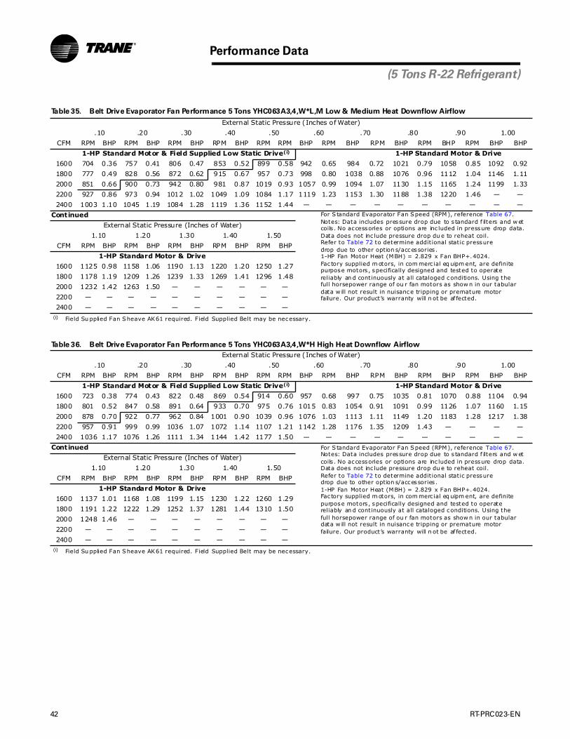
42 RT-PRC023-EN
Performance Data
(5 Tons R-22 Refrigerant)
Table 35. Belt Drive Evaporator Fan Performance 5 Tons YHC063A3,4,W*L,M Low & Medium Heat Downflow Airflow
External Static Pressure (Inches of Water)
.10 .20 .30 .40 .50 .60 .70 .80 .90 1.00
CFM RPM BHP RPM BHP RPM BHP RPM BHP RPM RPM BHP RPM BHP RPM BHP RPM BHP RPM BHP BHP
1-HP Standard Motor & Field Supplied Low Static Drive(i)
(i) Field Su pplied Fan Sheave AK61 required. Field Supplied Belt may be necessary.
1-HP Standard Motor & Drive
1600 704 0.36 757 0.41 806 0.47 853 0.52 899 0.58 942 0.65 984 0.72 1021 0.79 1058 0.85 1092 0.92
1800 777 0.49 828 0.56 872 0.62 915 0.67 957 0.73 998 0.80 1038 0.88 1076 0.96 1112 1.04 1146 1.11
2000 851 0.66 900 0.73 942 0.80 981 0.87 1019 0.93 1057 0.99 1094 1.07 1130 1.15 1165 1.24 1199 1.33
2200 927 0.86 973 0.94 1012 1.02 1049 1.09 1084 1.17 1119 1.23 1153 1.30 1188 1.38 1220 1.46 — —
2400 1003 1.10 1045 1.19 1084 1.28 1119 1.36 1152 1.44 — — — — — — — — — —
Continued For S tandard Evaporator Fan Speed (RPM), reference Table 67.Notes: Data includes pressure drop due to s tandard f ilters and w etcoils . No accessories or options are inc luded in pressure drop data.Data does not inc lude pressure drop du e to reheat coil.Refer to Table 72 to determine addit ional static pressuredrop due to other option s/accessories .1-HP Fan Motor Heat (MBH) = 2.829 x Fan BHP+.4024.Fac tory supplied m otors, in com merc ial eq uipm ent, are definitepurpose motors , specifically designed and tested to operate reliably an d continuously at all cataloged conditions. Using thefull horsepower range of ou r fan motors as show n in our tabulardata w ill not result in nuisance tripping or premature motor failure. Our product’s warranty will n ot be af fected.
External Static Pressure (Inches of Water)
1.10 1.20 1.30 1.40 1.50
CFM RPM BHP RPM BHP RPM BHP RPM BHP RPM BHP
1-HP Standard Motor & Drive
1600 1125 0.98 1158 1.06 1190 1.13 1220 1.20 1250 1.27
1800 1178 1.19 1209 1.26 1239 1.33 1269 1.41 1296 1.48
2000 1232 1.42 1263 1.50 — — — — — —
2200 — — — — — — — — — —
2400 — — — — — — — — — —
Table 36. Belt Drive Evaporator Fan Performance 5 Tons YHC063A3,4,W*H High Heat Downflow Airflow
External Static Pressure (Inches of Water)
.10 .20 .30 .40 .50 .60 .70 .80 .90 1.00
CFM RPM BHP RPM BHP RPM BHP RPM BHP RPM RPM BHP RPM BHP RPM BHP RPM BHP RPM BHP BHP
1-HP Standard Motor & Field Supplied Low Static Drive(i)
(i) Field Su pplied Fan Sheave AK61 required. Field Supplied Belt may be necessary.
1-HP Standard Motor & Drive
1600 723 0.38 774 0.43 822 0.48 869 0.54 914 0.60 957 0.68 997 0.75 1035 0.81 1070 0.88 1104 0.94
1800 801 0.52 847 0.58 891 0.64 933 0.70 975 0.76 1015 0.83 1054 0.91 1091 0.99 1126 1.07 1160 1.15
2000 878 0.70 922 0.77 962 0.84 1001 0.90 1039 0.96 1076 1.03 1113 1.11 1149 1.20 1183 1.28 1217 1.38
2200 957 0.91 999 0.99 1036 1.07 1072 1.14 1107 1.21 1142 1.28 1176 1.35 1209 1.43 — — — —
2400 1036 1.17 1076 1.26 1111 1.34 1144 1.42 1177 1.50 — — — — — — — — — —
Continued For S tandard Evaporator Fan Speed (RPM), reference Table 67.Notes: Data includes pressure drop due to s tandard f ilters and w etcoils . No accessories or options are inc luded in pressure drop data.Data does not inc lude pressure drop du e to reheat coil.Refer to Table 72 to determine addit ional static pressuredrop due to other option s/accessories .1-HP Fan Motor Heat (MBH) = 2.829 x Fan BHP+.4024.Fac tory supplied m otors, in com merc ial eq uipm ent, are definitepurpose motors , specifically designed and tested to operate reliably an d continuously at all cataloged conditions. Using thefull horsepower range of ou r fan motors as show n in our tabulardata w ill not result in nuisance tripping or premature motor failure. Our product’s warranty will n ot be af fected.
External Static Pressure (Inches of Water)
1.10 1.20 1.30 1.40 1.50
CFM RPM BHP RPM BHP RPM BHP RPM BHP RPM BHP
1-HP Standard Motor & Drive
1600 1137 1.01 1168 1.08 1199 1.15 1230 1.22 1260 1.29
1800 1191 1.22 1222 1.29 1252 1.37 1281 1.44 1310 1.50
2000 1248 1.46 — — — — — — — —
2200 — — — — — — — — — —
2400 — — — — — — — — — —

RT-PRC023-EN 43
Performance Data
(5 Tons R-22 Refrigerant)
Table 37. Belt Drive Evaporator Fan Performance 5 Tons YHC063A3,4,W*L,M Low & Medium Heat Horizontal Airflow
External Static Pressure (Inches of Water)
.10 .20 .30 .40 .50 .60 .70 .80 .90 1.00
CFM RPM BHP RPM BHP RPM BHP RPM BHP RPM RPM BHP RPM BHP RPM BHP RPM BHP RPM BHP BHP
1-HP Standard Motor & Field Supplied Low Static Drive(i)
(i) Field Su pplied Fan Sheave AK61 required. Field Supplied Belt may be necessary.
1-HP Standard Motor & Drive
1600 775 0.42 837 0.50 898 0.57 952 0.65 1000 0.72 1044 0.79 1086 0.87 1127 0.95 1166 1.03 1203 1.11
1800 856 0.58 912 0.66 967 0.74 1020 0.83 1069 0.91 1112 1.00 1152 1.08 1189 1.16 1227 1.25 1263 1.34
2000 939 0.77 990 0.86 1040 0.96 1089 1.05 1136 1.14 1180 1.24 1219 1.33 1256 1.42 1292 1.50 — —
2200 1023 1.01 1070 1.11 1115 1.21 1160 1.31 1205 1.41 — — — — — — — — — —
2400 1108 1.29 1151 1.39 1193 1.50 — — — — — — — — — — — — — —
Continued For S tandard Evaporator Fan Speed (RPM), reference Table 67.Notes: Data includes pressure drop due to s tandard f ilters and w etcoils . No accessories or options are inc luded in pressure drop data.Data does not inc lude pressure drop du e to reheat coil.Refer to Table 72 to determine addit ional static pressuredrop due to other option s/accessories .1-HP Fan Motor Heat (MBH) = 2.829 x Fan BHP+.4024.Fac tory supplied m otors, in com merc ial eq uipm ent, are definitepurpose motors , specifically designed and tested to operate reliably an d continuously at all cataloged conditions. Using thefull horsepower range of ou r fan motors as show n in our tabulardata w ill not result in nuisance tripping or premature motor failure. Our product’s warranty will n ot be af fected.
External Static Pressure (Inches of Water)
1.10 1.20 1.30 1.40
CFM RPM BHP RPM BHP RPM BHP RPM BHP
1-HP Standard Motor & Drive
1600 1239 1.19 1272 1.28 1304 1.37 1336 1.46
1800 1299 1.43 — — — — — —
2000 — — — — — — — —
2200 — — — — — — — —
2400 — — — — — — — —
Table 38. Belt Drive Evaporator Fan Performance 5 Tons YHC063A3,4,W*H High Heat Horizontal Airflow
External Static Pressure (Inches of Water)
.10 .20 .30 .40 .50 .60 .70 .80 .90 1.00
CFM RPM BHP RPM BHP RPM BHP RPM BHP RPM RPM BHP RPM BHP RPM BHP RPM BHP RPM BHP BHP
1-HP Standard Motor & Field Supplied Low Static Drive(i)
(i) Field Su pplied Fan Sheave AK61 required. Field Supplied Belt may be necessary.
1-HP Standard Motor & Drive
1600 796 0.45 858 0.52 917 0.60 969 0.67 1015 0.75 1059 0.82 1100 0.90 1141 0.98 1178 1.06 1216 1.14
1800 881 0.61 935 0.70 991 0.78 1042 0.87 1087 0.95 1129 1.03 1168 1.12 1206 1.20 1244 1.29 1279 1.38
2000 967 0.82 1016 0.91 1066 1.01 1115 1.10 1160 1.19 1201 1.28 1239 1.38 1275 1.47 — — — —
2200 1054 1.07 1099 1.17 1144 1.27 1189 1.38 1233 1.48 — — — — — — — — — —
2400 1141 1.37 1183 1.48 — — — — — — — — — — — — — — — —
Continued For Standard Evap orator Fan Speed (RPM), reference Table 67.Notes: Data inc lu des pressu re drop due to stan dard filters and wetcoils. No accessories or options are included in pressure drop data.Data does not include pressure drop due to reh eat coil.Refer to Table 72 to determine additional static pressuredrop due to other op tions/accessories.1-HP Fan Motor Heat (MBH) = 2.829 x Fan BHP+.402 4.Factory supplied motors, in commercial equipment, are definitepurpose m otors, spec if ically des ign ed and tes ted to operate reliably and continuous ly at all cataloged conditions . Using thefull horsepower range of our fan motors as shown in ou r tabulardata will not resu lt in nuisance tripping or prem ature motor failure. Our produc t’s warranty will not be affec ted.
External Static Pressure (Inches of Water)
1.10 1.20 1.30 1.40
CFM RPM BHP RPM BHP RPM BHP RPM BHP
1-HP Standard Motor & Drive
1600 1251 1.22 1283 1.31 1315 1.40 1345 1.49
1800 1313 1.47 — — — — — —
2000 — — — — — — — —
2200 — — — — — — — —
2400 — — — — — — — —

44 RT-PRC023-EN
Table 39. Multispeed Direct Drive Evaporator Fan Performance 3 – 5 Tons — No Electric Heat — TSC036E1, TSC048E1, TSC060E1
External Static Pressure (Inches of Water) & Motor Pow er (Bhp)(i)
(i) Data includes pressure drop du e to wet coil and filters.
Unit ModelRated
Speed Set 1Standard Low Speed
Speed Set 2Mid Speed
Speed Set 3Standard High Speed
Speed Set 4OS High Speed
Speed Set 5Tons Nu mber CFM ESP RPM BHP ESP RPM BHP ESP RPM BHP ESP RPM BHP ESP RPM BHP
3 TSC036E1 960 0.45 715 0.21 0.74 851 0.31 0.92 929 0.38 1.07 993 0.44 1.25 1053 0.52Downflow 1020 0.39 695 0.20 0.66 826 0.30 0.84 905 0.37 0.99 969 0.43 1.17 1030 0.50
Airflow 1080 0.33 675 0.20 0.59 800 0.29 0.77 880 0.36 0.91 945 0.42 1.08 1007 0.491140 0.27 654 0.19 0.51 774 0.28 0.69 855 0.35 0.83 921 0.41 1.00 985 0.481200 0.21 634 0.18 0.43 749 0.27 0.61 831 0.34 0.75 898 0.40 0.91 962 0.471260 0.15 614 0.18 0.35 723 0.26 0.53 806 0.33 0.67 874 0.39 0.83 939 0.461320 0.09 593 0.17 0.28 697 0.25 0.45 782 0.32 0.59 850 0.38 0.74 916 0.451380 0.03 573 0.17 0.20 671 0.24 0.37 757 0.31 0.51 826 0.37 0.66 893 0.441440 — — — 0.12 646 0.23 0.29 732 0.30 0.43 802 0.36 0.57 871 0.43
TSC036E1 960 0.45 711 0.21 0.70 835 0.30 0.89 913 0.37 1.04 978 0.44 1.21 1037 0.51Horizontal 1020 0.39 689 0.20 0.63 811 0.29 0.81 890 0.36 0.96 957 0.43 1.13 1016 0.50
Airflow 1080 0.32 667 0.19 0.56 787 0.28 0.73 868 0.35 0.88 935 0.42 1.04 996 0.491140 0.26 644 0.19 0.48 763 0.28 0.65 845 0.34 0.80 913 0.41 0.95 975 0.481200 0.20 622 0.18 0.41 739 0.27 0.57 823 0.33 0.72 892 0.40 0.87 955 0.471260 0.13 599 0.17 0.33 715 0.26 0.50 800 0.32 0.64 870 0.39 0.78 934 0.461320 0.07 577 0.17 0.26 691 0.25 0.42 777 0.32 0.56 848 0.38 0.69 913 0.451380 0.01 555 0.16 0.18 667 0.24 0.34 755 0.31 0.48 826 0.37 0.61 893 0.441440 — — — 0.11 642 0.23 0.26 732 0.30 0.40 805 0.36 0.52 872 0.43
4 TSC048E1 1280 0.60 865 0.36 0.84 977 0.47 1.02 1044 0.55 1.17 1090 0.63 — — —Downflow 1360 0.48 833 0.35 0.72 944 0.45 0.90 1012 0.54 1.04 1062 0.61 — — —
Airflow 1440 0.37 802 0.34 0.60 912 0.44 0.77 980 0.52 0.92 1033 0.60 — — —1520 0.25 770 0.32 0.48 879 0.42 0.65 948 0.50 0.80 1005 0.58 1.06 1100 0.691600 0.14 739 0.31 0.36 846 0.41 0.52 915 0.49 0.68 976 0.56 0.92 1069 0.671680 0.02 707 0.30 0.24 814 0.39 0.39 883 0.47 0.56 948 0.55 0.78 1038 0.651760 — — — 0.13 781 0.38 0.27 851 0.45 0.43 920 0.53 0.64 1006 0.631840 — — — 0.01 748 0.36 0.14 819 0.43 0.31 891 0.52 0.50 975 0.621920 — — — — — — 0.02 787 0.42 0.19 863 0.50 0.37 944 0.60
TSC048E1 1280 0.61 864 0.36 0.84 967 0.47 1.00 1038 0.55 1.16 1115 0.65 — — —Horizontal 1360 0.51 831 0.35 0.73 935 0.45 0.88 1006 0.53 1.05 1084 0.63 — — —
Airflow 1440 0.40 798 0.33 0.62 904 0.44 0.77 974 0.52 0.94 1052 0.61 1.10 1114 0.701520 0.30 766 0.32 0.51 873 0.42 0.66 943 0.50 0.82 1020 0.59 0.99 1084 0.681600 0.19 733 0.31 0.40 842 0.41 0.55 911 0.48 0.71 989 0.57 0.87 1054 0.661680 0.09 701 0.29 0.29 810 0.39 0.44 879 0.47 0.60 957 0.55 0.75 1023 0.651760 — — — 0.18 779 0.38 0.32 848 0.45 0.48 925 0.54 0.64 993 0.631840 — — — 0.08 748 0.36 0.21 816 0.43 0.37 893 0.52 0.52 963 0.611920 — — — — — — 0.10 784 0.42 0.26 861 0.50 0.40 932 0.59
5 TSC060E1 1600 0.75 1006 0.60 0.91 1065 0.69 — — — — — — — — —Downflow 1700 0.60 969 0.58 0.75 1024 0.66 0.96 1101 0.77 — — — — — —
Airflow 1800 0.45 933 0.56 0.58 982 0.63 0.78 1059 0.74 — — — — — —1900 0.30 896 0.54 0.42 941 0.61 0.61 1017 0.71 0.82 1105 0.83 — — —2000 0.14 860 0.52 0.25 899 0.58 0.43 975 0.68 0.64 1062 0.80 0.70 1083 0.852100 0.00 826 0.50 0.09 858 0.55 0.25 933 0.65 0.46 1019 0.77 0.54 1045 0.822200 — — — — — — 0.08 891 0.62 0.28 975 0.74 0.37 1007 0.792300 — — — — — — — — — 0.10 932 0.70 0.20 969 0.762400 — — — — — — — — — — — — 0.03 931 0.73
TSC060E1 1600 0.73 1003 0.60 0.90 1075 0.69 — — — — — — — — —Horizontal 1700 0.60 968 0.58 0.74 1034 0.67 0.89 1104 0.77 — — — — — —
Airflow 1800 0.46 934 0.56 0.59 993 0.64 0.74 1064 0.74 — — — — — —1900 0.33 899 0.54 0.44 952 0.62 0.59 1023 0.71 0.75 1095 0.83 — — —2000 0.19 864 0.52 0.28 911 0.59 0.43 983 0.69 0.60 1053 0.79 0.69 1090 0.862100 0.05 829 0.50 0.13 870 0.56 0.28 942 0.66 0.44 1012 0.76 0.53 1051 0.832200 — — — 0.00 837 0.54 0.13 902 0.63 0.28 971 0.73 0.37 1012 0.802300 — — — — — — 0.00 868 0.61 0.12 930 0.70 0.21 972 0.772400 — — — — — — — — — 0.00 897 0.68 0.06 933 0.74
For 036 Models, fan m otor heat (MBH) = 2 .72 x Fan Bhp + 0.16.For 048 & 060 Models , fan motor heat (MBH) = 2.87 x Fan Bhp + 0.15.Factory supplied motors, in comm erc ial equipm en t, are def inite purpose motors, spec ifically des igned and tested to op erate reliably and con tinuously atall cataloged conditions . Using the full horsepower range of our fan motors as shown in our tabular data will not resu lt in nuisan ce tripping or prematurem otor failure. Our produc t’s warran ty w ill not be affected.
Performance Data

RT-PRC023-EN 45
Performance Data
Table 40. Multispeed Direct Drive Evaporator Fan Performance 3 – 5 Tons — Low & Medium Gas Heat — YSC036E1, YSC048E1,
YSC060E1
E xternal Static Pressure (In ches of Water) & Motor Power (Bhp)(i)
(i) Data includes pressure drop du e to wet coil and filters.
Unit ModelRated
Speed Set 1Standard Low Speed
Speed Set 2Mid Speed
Speed Set 3Standard High Speed
Speed Set 4OS High Speed
Speed Set 5Tons Nu mber CFM ESP RPM BHP ESP RPM BHP E SP RPM BHP E SP RPM BHP E SP RPM BHP
3 YSC036E1**L,M 960 0.43 718 0.19 0.64 825 0.27 0.88 923 0.35 1.12 1017 0.46 1.28 1074 0.52Downflow 1020 0.37 696 0.18 0.57 800 0.26 0.80 900 0.35 1.04 997 0.45 1.20 1053 0.51
Airflow 1080 0.30 675 0.18 0.49 775 0.26 0.72 877 0.34 0.96 977 0.44 1.11 1033 0.501140 0.24 654 0.17 0.42 749 0.25 0.64 854 0.33 0.87 957 0.43 1.03 1013 0.491200 0.18 633 0.17 0.34 724 0.24 0.56 832 0.32 0.79 938 0.42 0.94 992 0.481260 0.11 612 0.16 0.26 698 0.23 0.48 809 0.31 0.71 918 0.41 0.86 972 0.471320 0.05 590 0.16 0.19 673 0.22 0.39 786 0.30 0.63 898 0.40 0.77 951 0.461380 — — — 0.11 647 0.21 0.31 763 0.29 0.55 878 0.39 0.68 931 0.451440 — — — 0.03 622 0.21 0.23 740 0.28 0.47 859 0.38 0.60 910 0.44
YSC036E1**L,M 960 0.42 715 0.19 0.67 842 0.28 0.90 937 0.36 1.15 1037 0.46 1.25 1062 0.51Horizontal 1020 0.37 695 0.18 0.61 819 0.27 0.83 916 0.35 1.07 1014 0.45 1.18 1047 0.50
Airflow 1080 0.31 675 0.18 0.54 796 0.26 0.75 895 0.34 0.99 992 0.44 1.11 1032 0.501140 0.26 654 0.17 0.47 772 0.26 0.68 874 0.34 0.91 970 0.43 1.04 1017 0.491200 0.20 634 0.17 0.41 749 0.25 0.61 853 0.33 0.83 948 0.42 0.97 1002 0.481260 0.14 614 0.16 0.34 725 0.24 0.54 832 0.32 0.75 926 0.41 0.90 987 0.481320 0.09 594 0.16 0.27 702 0.23 0.47 811 0.31 0.67 903 0.40 0.83 972 0.471380 0.03 574 0.15 0.20 678 0.22 0.40 789 0.30 0.59 881 0.39 0.76 957 0.461440 — — — 0.14 654 0.22 0.33 768 0.29 0.51 859 0.38 0.69 942 0.45
4 YSC048E1**L,M 1280 0.71 933 0.42 0.89 1003 0.49 1.11 1094 0.59 — — — — — —Downflow 1360 0.59 903 0.41 0.76 973 0.48 0.97 1061 0.57 1.14 1116 0.64 — — —
Airflow 1440 0.47 874 0.39 0.63 943 0.46 0.84 1027 0.56 1.00 1085 0.62 — — —1520 0.34 845 0.38 0.50 913 0.45 0.70 993 0.54 0.86 1053 0.61 1.05 1122 0.701600 0.22 815 0.37 0.38 883 0.43 0.56 959 0.52 0.72 1021 0.59 0.90 1089 0.681680 0.10 786 0.36 0.25 852 0.42 0.42 926 0.50 0.58 990 0.57 0.76 1057 0.661760 — — — 0.12 822 0.41 0.28 892 0.48 0.45 958 0.55 0.61 1024 0.641840 — — — — — — 0.15 858 0.46 0.31 926 0.53 0.47 992 0.621920 — — — — — — 0.01 824 0.45 0.17 895 0.51 0.32 960 0.60
YSC048E1**L,M 1280 0.66 894 0.40 0.81 967 0.48 1.01 1051 0.57 1.14 1101 0.63 — — —Horizontal 1360 0.54 863 0.39 0.70 935 0.46 0.88 1016 0.55 1.01 1069 0.61 — — —
Airflow 1440 0.43 831 0.38 0.58 904 0.45 0.76 982 0.53 0.89 1037 0.60 1.05 1101 0.691520 0.31 799 0.36 0.47 872 0.43 0.63 947 0.51 0.77 1006 0.58 0.93 1069 0.671600 0.20 768 0.35 0.35 840 0.41 0.51 912 0.49 0.64 974 0.56 0.80 1037 0.651680 0.08 736 0.33 0.24 809 0.40 0.38 877 0.47 0.52 942 0.54 0.67 1005 0.631760 — — — 0.12 777 0.38 0.26 842 0.46 0.40 911 0.52 0.55 973 0.611840 — — — 0.01 745 0.37 0.13 807 0.44 0.28 879 0.51 0.42 941 0.591920 — — — — — — 0.00 773 0.42 0.15 847 0.49 0.29 909 0.57
5 YSC060E1**L,M 1600 0.97 1110 0.71 — — — — — — — — — — — —Downflow 1700 0.79 1068 0.68 0.91 1120 0.77 — — — — — — — — —
Airflow 1800 0.60 1026 0.66 0.73 1079 0.74 — — — — — — — — —1900 0.42 984 0.63 0.54 1038 0.71 0.69 1093 0.78 — — — — — —2000 0.24 942 0.60 0.36 997 0.68 0.50 1050 0.74 0.60 1079 0.82 — — —2100 0.06 900 0.57 0.18 956 0.65 0.31 1006 0.71 0.42 1040 0.79 0.52 1078 0.862200 — — — 0.00 916 0.63 0.12 963 0.68 0.24 1001 0.76 0.32 1036 0.832300 — — — — — — 0.00 936 0.66 0.05 962 0.73 0.13 994 0.792400 — — — — — — — — — — — — 0.00 965 0.77
YSC060E1**L,M 1600 0.83 1054 0.67 — — — — — — — — — — — —Horizontal 1700 0.67 1013 0.65 0.83 1084 0.74 — — — — — — — — —
Airflow 1800 0.51 971 0.62 0.65 1039 0.71 0.75 1075 0.76 — — — — — —1900 0.36 930 0.59 0.48 995 0.68 0.57 1031 0.73 0.72 1086 0.82 — — —2000 0.20 888 0.57 0.30 951 0.65 0.39 987 0.70 0.54 1045 0.79 0.67 1092 0.872100 0.04 847 0.54 0.12 907 0.62 0.21 942 0.67 0.36 1004 0.76 0.48 1051 0.842200 — — — 0.00 877 0.60 0.02 898 0.64 0.17 963 0.73 0.29 1010 0.812300 — — — — — — — — — 0.00 924 0.70 0.10 968 0.772400 — — — — — — — — — — — — 0.00 946 0.76
For 036 Models, fan m otor heat (MBH) = 2 .72 x Fan Bhp + 0.16.For 048 & 060 Models , fan motor heat (MBH) = 2.87 x Fan Bhp + 0.15.Factory supplied motors, in comm erc ial equipm en t, are def inite purpose motors, spec ifically des igned and tested to op erate reliably and con tinuously atall cataloged condit ions . Us ing the full horsepower range of our fan m otors as shown in our tabular data will n ot result in nuisan ce tripping or p rematurem otor failure. Our produc t’s warran ty w ill not be affected.
(3-5 Tons R-410A Refrigerant)
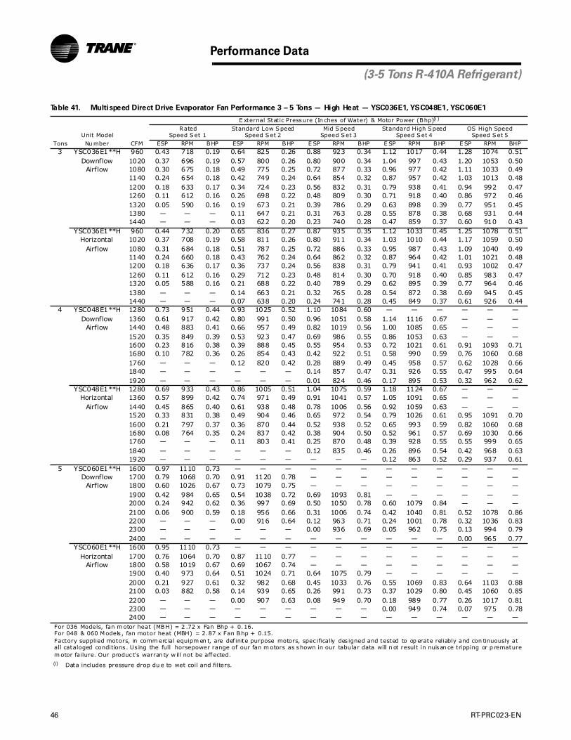
46 RT-PRC023-EN
Performance Data
(3-5 Tons R-410A Refrigerant)
Table 41. Multispeed Direct Drive Evaporator Fan Performance 3 – 5 Tons — High Heat — YSC036E1, YSC048E1, YSC060E1
E xternal Static Pressure (In ches of Water) & Motor Power (Bhp)(i)
(i) Data includes pressure drop du e to wet coil and filters.
Unit ModelRated
Speed Set 1Standard Low Speed
Speed Set 2Mid Speed
Speed Set 3Standard High Speed
Speed Set 4OS High Speed
Speed Set 5Tons Nu mber CFM ESP RPM BHP ESP RPM BHP E SP RPM BHP E SP RPM BHP E SP RPM BHP
3 YSC036E1**H 960 0.43 718 0.19 0.64 825 0.26 0.88 923 0.34 1.12 1017 0.44 1.28 1074 0.51Downflow 1020 0.37 696 0.19 0.57 800 0.26 0.80 900 0.34 1.04 997 0.43 1.20 1053 0.50
Airflow 1080 0.30 675 0.18 0.49 775 0.25 0.72 877 0.33 0.96 977 0.42 1.11 1033 0.491140 0.24 654 0.18 0.42 749 0.24 0.64 854 0.32 0.87 957 0.42 1.03 1013 0.481200 0.18 633 0.17 0.34 724 0.23 0.56 832 0.31 0.79 938 0.41 0.94 992 0.471260 0.11 612 0.16 0.26 698 0.22 0.48 809 0.30 0.71 918 0.40 0.86 972 0.461320 0.05 590 0.16 0.19 673 0.21 0.39 786 0.29 0.63 898 0.39 0.77 951 0.451380 — — — 0.11 647 0.21 0.31 763 0.28 0.55 878 0.38 0.68 931 0.441440 — — — 0.03 622 0.20 0.23 740 0.28 0.47 859 0.37 0.60 910 0.43
YSC036E1**H 960 0.44 732 0.20 0.65 836 0.27 0.87 935 0.35 1.12 1033 0.45 1.25 1078 0.51Horizontal 1020 0.37 708 0.19 0.58 811 0.26 0.80 911 0.34 1.03 1010 0.44 1.17 1059 0.50
Airflow 1080 0.31 684 0.18 0.51 787 0.25 0.72 886 0.33 0.95 987 0.43 1.09 1040 0.491140 0.24 660 0.18 0.43 762 0.24 0.64 862 0.32 0.87 964 0.42 1.01 1021 0.481200 0.18 636 0.17 0.36 737 0.24 0.56 838 0.31 0.79 941 0.41 0.93 1002 0.471260 0.11 612 0.16 0.29 712 0.23 0.48 814 0.30 0.70 918 0.40 0.85 983 0.471320 0.05 588 0.16 0.21 688 0.22 0.40 789 0.29 0.62 895 0.39 0.77 964 0.461380 — — — 0.14 663 0.21 0.32 765 0.28 0.54 872 0.38 0.69 945 0.451440 — — — 0.07 638 0.20 0.24 741 0.28 0.45 849 0.37 0.61 926 0.44
4 YSC048E1**H 1280 0.73 951 0.44 0.93 1025 0.52 1.10 1084 0.60 — — — — — —Downflow 1360 0.61 917 0.42 0.80 991 0.50 0.96 1051 0.58 1.14 1116 0.67 — — —
Airflow 1440 0.48 883 0.41 0.66 957 0.49 0.82 1019 0.56 1.00 1085 0.65 — — —1520 0.35 849 0.39 0.53 923 0.47 0.69 986 0.55 0.86 1053 0.63 — — —1600 0.23 816 0.38 0.39 888 0.45 0.55 954 0.53 0.72 1021 0.61 0.91 1093 0.711680 0.10 782 0.36 0.26 854 0.43 0.42 922 0.51 0.58 990 0.59 0.76 1060 0.681760 — — — 0.12 820 0.42 0.28 889 0.49 0.45 958 0.57 0.62 1028 0.661840 — — — — — — 0.14 857 0.47 0.31 926 0.55 0.47 995 0.641920 — — — — — — 0.01 824 0.46 0.17 895 0.53 0.32 962 0.62
YSC048E1**H 1280 0.69 933 0.43 0.86 1005 0.51 1.04 1075 0.59 1.18 1124 0.67 — — —Horizontal 1360 0.57 899 0.42 0.74 971 0.49 0.91 1041 0.57 1.05 1091 0.65 — — —
Airflow 1440 0.45 865 0.40 0.61 938 0.48 0.78 1006 0.56 0.92 1059 0.63 — — —1520 0.33 831 0.38 0.49 904 0.46 0.65 972 0.54 0.79 1026 0.61 0.95 1091 0.701600 0.21 797 0.37 0.36 870 0.44 0.52 938 0.52 0.65 993 0.59 0.82 1060 0.681680 0.08 764 0.35 0.24 837 0.42 0.38 904 0.50 0.52 961 0.57 0.69 1030 0.661760 — — — 0.11 803 0.41 0.25 870 0.48 0.39 928 0.55 0.55 999 0.651840 — — — — — — 0.12 835 0.46 0.26 896 0.54 0.42 968 0.631920 — — — — — — — — — 0.12 863 0.52 0.29 937 0.61
5 YSC060E1**H 1600 0.97 1110 0.73 — — — — — — — — — — — —Downflow 1700 0.79 1068 0.70 0.91 1120 0.78 — — — — — — — — —
Airflow 1800 0.60 1026 0.67 0.73 1079 0.75 — — — — — — — — —1900 0.42 984 0.65 0.54 1038 0.72 0.69 1093 0.81 — — — — — —2000 0.24 942 0.62 0.36 997 0.69 0.50 1050 0.78 0.60 1079 0.84 — — —2100 0.06 900 0.59 0.18 956 0.66 0.31 1006 0.74 0.42 1040 0.81 0.52 1078 0.862200 — — — 0.00 916 0.64 0.12 963 0.71 0.24 1001 0.78 0.32 1036 0.832300 — — — — — — 0.00 936 0.69 0.05 962 0.75 0.13 994 0.792400 — — — — — — — — — — — — 0.00 965 0.77
YSC060E1**H 1600 0.95 1110 0.73 — — — — — — — — — — — —Horizontal 1700 0.76 1064 0.70 0.87 1110 0.77 — — — — — — — — —
Airflow 1800 0.58 1019 0.67 0.69 1067 0.74 — — — — — — — — —1900 0.40 973 0.64 0.51 1024 0.71 0.64 1075 0.79 — — — — — —2000 0.21 927 0.61 0.32 982 0.68 0.45 1033 0.76 0.55 1069 0.83 0.64 1103 0.882100 0.03 882 0.58 0.14 939 0.65 0.26 991 0.73 0.37 1029 0.80 0.45 1060 0.852200 — — — 0.00 907 0.63 0.08 949 0.70 0.18 989 0.77 0.26 1017 0.812300 — — — — — — — — — 0.00 949 0.74 0.07 975 0.782400 — — — — — — — — — — — — — — —
For 036 Models, fan m otor heat (MBH) = 2 .72 x Fan Bhp + 0.16.For 048 & 060 Models , fan motor heat (MBH) = 2.87 x Fan Bhp + 0.15.Factory supplied motors, in comm erc ial equipm en t, are def inite purpose motors, spec ifically des igned and tested to op erate reliably and con tinuously atall cataloged condit ions . Us ing the full horsepower range of our fan m otors as shown in our tabular data will n ot result in nuisan ce tripping or p rematurem otor failure. Our produc t’s warran ty w ill not be affected.

RT-PRC023-EN 47
Performance Data
(3-5 Tons R-410A Refrigerant)
Table 42. Multispeed Direct Drive Evaporator Fan Performance 3 – 5 Tons — WSC036E1, WSC048E1, WSC060E1
E xternal Static Pressure (In ches of Water) & Motor Power (Bhp)(i)
(i) Data includes pressure drop du e to wet coil and filters.
Unit ModelRated
Speed Set 1Standard Low Speed
Speed Set 2Mid Speed
Speed Set 3Standard High Speed
Speed Set 4OS High Speed
Speed Set 5Tons Nu mber CFM ESP RPM BHP ESP RPM BHP E SP RPM BHP E SP RPM BHP E SP RPM BHP
3 WSC036E1 960 0.43 707 0.21 0.70 843 0.38 0.88 919 0.38 1.02 979 0.36 1.15 1027 0.50Downflow 1020 0.37 687 0.20 0.62 818 0.37 0.80 896 0.37 0.94 956 0.35 1.07 1006 0.49
Airflow 1080 0.31 668 0.19 0.55 792 0.36 0.73 872 0.36 0.87 933 0.34 0.99 985 0.481140 0.25 648 0.19 0.47 766 0.35 0.65 849 0.35 0.79 911 0.33 0.91 964 0.471200 0.19 628 0.18 0.39 740 0.34 0.57 826 0.34 0.71 888 0.32 0.83 943 0.461260 0.13 609 0.18 0.31 715 0.32 0.50 803 0.33 0.63 866 0.32 0.75 922 0.451320 0.07 589 0.17 0.24 689 0.31 0.42 780 0.32 0.56 843 0.31 0.68 901 0.441380 0.01 569 0.17 0.16 663 0.30 0.34 757 0.31 0.48 820 0.30 0.60 880 0.431440 — — — 0.08 637 0.29 0.26 734 0.30 0.40 798 0.29 0.52 859 0.42
WSC036E1 960 0.40 707 0.21 0.69 856 0.31 0.88 941 0.39 1.03 987 0.45 1.16 1034 0.50Horizontal 1020 0.35 688 0.20 0.62 831 0.30 0.80 916 0.38 0.95 967 0.44 1.08 1011 0.49
Airflow 1080 0.30 669 0.19 0.55 806 0.29 0.73 891 0.37 0.87 947 0.43 1.00 989 0.481140 0.24 650 0.19 0.48 781 0.28 0.65 866 0.36 0.79 927 0.42 0.92 966 0.471200 0.19 631 0.18 0.41 756 0.28 0.58 841 0.35 0.71 906 0.41 0.84 943 0.461260 0.14 612 0.18 0.34 731 0.27 0.50 816 0.34 0.63 886 0.40 0.76 920 0.451320 0.09 593 0.17 0.26 706 0.26 0.43 791 0.33 0.55 866 0.39 0.68 898 0.441380 0.04 574 0.17 0.19 681 0.25 0.35 766 0.32 0.47 846 0.38 0.60 875 0.431440 — — — 0.12 655 0.24 0.28 741 0.30 0.40 826 0.37 0.52 852 0.42
4 WSC048E1 1280 0.60 865 0.36 0.84 977 0.47 1.02 1044 0.55 1.17 1090 0.63 — — —Downflow 1360 0.48 833 0.35 0.72 944 0.45 0.90 1012 0.54 1.04 1062 0.61 — — —
Airflow 1440 0.37 802 0.34 0.60 912 0.44 0.77 980 0.52 0.92 1033 0.60 — — —1520 0.25 770 0.32 0.48 879 0.42 0.65 948 0.50 0.80 1005 0.58 1.06 1100 0.691600 0.14 739 0.31 0.36 846 0.41 0.52 915 0.49 0.68 976 0.56 0.92 1069 0.671680 0.02 707 0.30 0.24 814 0.39 0.39 883 0.47 0.56 948 0.55 0.78 1038 0.651760 — — — 0.13 781 0.38 0.27 851 0.45 0.43 920 0.53 0.64 1006 0.631840 — — — 0.01 748 0.36 0.14 819 0.43 0.31 891 0.52 0.50 975 0.621920 — — — — — — 0.02 787 0.42 0.19 863 0.50 0.37 944 0.60
WSC048E1 1280 0.61 864 0.36 0.84 967 0.47 1.00 1038 0.55 1.16 1115 0.65 — — —Horizontal 1360 0.51 831 0.35 0.73 935 0.45 0.88 1006 0.53 1.05 1084 0.63 — — —
Airflow 1440 0.40 798 0.33 0.62 904 0.44 0.77 974 0.52 0.94 1052 0.61 1.10 1114 0.701520 0.30 766 0.32 0.51 873 0.42 0.66 943 0.50 0.82 1020 0.59 0.99 1084 0.681600 0.19 733 0.31 0.40 842 0.41 0.55 911 0.48 0.71 989 0.57 0.87 1054 0.661680 0.09 701 0.29 0.29 810 0.39 0.44 879 0.47 0.60 957 0.55 0.75 1023 0.651760 — — — 0.18 779 0.38 0.32 848 0.45 0.48 925 0.54 0.64 993 0.631840 — — — 0.08 748 0.36 0.21 816 0.43 0.37 893 0.52 0.52 963 0.611920 — — — — — — 0.10 784 0.42 0.26 861 0.50 0.40 932 0.59
5 WSC060E1 1600 0.83 888 0.49 0.95 948 0.56 1.19 1048 0.67 — — — — — —Downflow 1700 0.69 847 0.46 0.82 908 0.53 1.04 1004 0.64 1.33 1110 0.78 — — —
Airflow 1800 0.56 806 0.44 0.69 867 0.51 0.90 959 0.62 1.18 1063 0.75 — — —1900 0.43 764 0.42 0.56 826 0.48 0.76 915 0.59 1.02 1016 0.71 — — —2000 0.30 723 0.40 0.43 785 0.46 0.62 870 0.56 0.87 969 0.68 1.18 1089 0.882100 0.16 681 0.37 0.30 744 0.44 0.47 826 0.53 0.71 922 0.65 1.03 1044 0.842200 0.03 640 0.35 0.17 703 0.41 0.33 781 0.50 0.56 876 0.61 0.87 999 0.812300 — — — 0.04 663 0.39 0.19 737 0.47 0.41 829 0.58 0.72 954 0.772400 — — — — — — 0.05 693 0.44 0.25 782 0.55 0.56 909 0.73
WSC060E1 1600 0.76 884 0.48 0.82 932 0.55 0.98 1022 0.66 1.13 1104 0.77 — — —Horizontal 1700 0.63 842 0.46 0.69 893 0.52 0.85 981 0.63 1.00 1061 0.74 — — —
Airflow 1800 0.50 801 0.44 0.57 854 0.50 0.72 941 0.60 0.87 1018 0.71 — — —1900 0.36 759 0.42 0.45 815 0.48 0.60 900 0.58 0.74 975 0.68 — — —2000 0.23 718 0.39 0.32 776 0.46 0.47 859 0.55 0.61 932 0.65 0.87 1069 0.862100 0.10 676 0.37 0.20 737 0.43 0.34 818 0.53 0.49 890 0.62 0.74 1025 0.832200 — — — 0.07 699 0.41 0.22 778 0.50 0.36 847 0.59 0.61 980 0.792300 — — — — — — 0.09 737 0.47 0.23 804 0.56 0.48 936 0.752400 — — — — — — — — — 0.10 761 0.53 0.35 892 0.72
For 036 Models, fan m otor heat (MBH) = 2 .72 x Fan Bhp + 0.16.For 048 & 060 Models , fan motor heat (MBH) = 2.87 x Fan Bhp + 0.15.Factory supplied motors, in comm erc ial equipm en t, are def inite purpose motors, spec ifically des igned and tested to op erate reliably and con tinuously atall cataloged condit ions . Us ing the full horsepower range of our fan m otors as shown in our tabular data will n ot result in nuisan ce tripping or p rematurem otor failure. Our produc t’s warran ty w ill not be affected.

48 RT-PRC023-EN
.
Table 43. Belt Drive Evaporator Fan Performance — 3 Tons — TSC036E3,E4,EW No Electric Heat Downflow Airflow
External Static Pressure (Inches of Water)
.10 .20 .30 .40 .50 .60 .70 .80 .90 1.00
CFM RPM BHP RPM BHP RPM BHP RPM BHP RPM RPM BHP RPM BHP RPM BHP RPM BHP RPM BHP BHP
1-HP Standard Motor & Field Supplied Low Static Drive(i)
(i) Field Su pplied Fan Sheave AK71x3/4" required. Field Supplied Belt may be necessary.
1-HP Standard Motor & Drive
960 — — — — 608 0.17 676 0.22 734 0.27 785 0.32 833 0.37 878 0.42 922 0.47 963 0.53
1080 — — 557 0.15 629 0.20 697 0.25 757 0.30 809 0.36 857 0.42 901 0.47 944 0.53 983 0.59
1200 — — 588 0.18 653 0.23 718 0.29 777 0.35 832 0.41 881 0.47 925 0.53 967 0.59 1006 0.66
1320 553 0.17 621 0.22 681 0.27 741 0.33 799 0.39 854 0.46 903 0.53 948 0.59 990 0.66 1030 0.73
1440 591 0.21 655 0.27 712 0.32 766 0.38 821 0.44 873 0.51 923 0.58 970 0.66 1014 0.73 1053 0.80
Continued For S tandard Evaporator Fan Speed (RPM), reference Table 67.Notes: Data includes pressure drop due to s tandard f ilters and w etcoils . No accessories or options are inc luded in pressure drop data.Data does not inc lude pressure drop du e to reheat coil.Refer to Table 72 to determine addit ional static pressuredrop due to other option s/accessories .1-HP Fan Motor Heat (MBH) = 2.767 2 x Fan BHP+ 0.4705 .Fac tory supplied m otors, in com merc ial eq uipm ent, are definitepurpose motors , specifically designed and tested to operate reliably an d continuously at all cataloged conditions. Using thefull horsepower range of ou r fan motors as show n in our tabulardata w ill not result in nuisance tripping or premature motor failure. Our product’s warranty will n ot be af fected.
External Static Pressure (Inches of Water)
1.10 1.20 1.30 1.40 1.50
CFM RPM BHP RPM BHP RPM BHP RPM BHP RPM BHP
1-HP Standard Motor & Drive
960 1002 0.59 1039 0.65 1073 0.70 1107 0.76 1138 0.82
1080 1022 0.65 1059 0.71 1095 0.78 1129 0.84 1162 0.91
1200 1044 0.72 1081 0.79 1115 0.85 1149 0.92 1183 0.99
1320 1068 0.80 1104 0.87 1138 0.94 1172 1.01 1205 1.08
1440 1091 0.88 1127 0.95 1161 1.03 1195 1.10 1227 1.18
1-HP Standard Motor & Field Supplied High Static Drive(ii)
(ii ) Field Su pplied Fan Sheave AK41x3/4" required. Field Supplied Belt may be necessary.
Table 44. Belt Drive Evaporator Fan Performance — 3 Tons — TSC036E3,E4,EW No Electric Heat Horizontal Airflow
External Static Pressure (Inches of Water)
.10 .20 .30 .40 .50 .60 .70 .80 .90 1.00
CFM RPM BHP RPM BHP RPM BHP RPM BHP RPM RPM BHP RPM BHP RPM BHP RPM BHP RPM BHP BHP
1-HP Standard Motor & Field Supplied Low Static Drive(i)
(i) Field Su pplied Fan Sheave AK71x3/4" required. Field Supplied Belt may be necessary.
1-HP Standard Motor & Drive
960 — — — — 619 0.16 680 0.20 738 0.25 791 0.30 840 0.35 885 0.39 927 0.44 968 0.49
1080 — — 570 0.14 647 0.19 708 0.24 762 0.29 814 0.34 863 0.39 908 0.45 950 0.50 991 0.55
1200 — — 595 0.17 674 0.23 736 0.28 789 0.33 839 0.39 885 0.44 931 0.50 973 0.56 1013 0.62
1320 551 0.16 622 0.20 698 0.26 764 0.33 817 0.38 866 0.44 911 0.50 954 0.56 997 0.62 1036 0.68
1440 588 0.20 653 0.24 722 0.30 789 0.37 846 0.44 894 0.50 938 0.56 980 0.63 1020 0.69 1060 0.76
Continued For S tandard Evaporator Fan Speed (RPM), reference Table 67.Notes: Data includes pressure drop due to s tandard f ilters and w etcoils . No accessories or options are inc luded in pressure drop data.Data does not inc lude pressure drop du e to reheat coil.Refer to Table 72 to determine addit ional static pressuredrop due to other option s/accessories .1-HP Fan Motor Heat (MBH) = 2.767 2 x Fan BHP+ 0.4705 .Fac tory supplied m otors, in com merc ial eq uipm ent, are definitepurpose motors , specifically designed and tested to operate reliably an d continuously at all cataloged conditions. Using thefull horsepower range of ou r fan motors as show n in our tabulardata w ill not result in nuisance tripping or premature motor failure. Our product’s warranty will n ot be af fected.
External Static Pressure (Inches of Water)
1.10 1.20 1.30 1.40 1.50
CFM RPM BHP RPM BHP RPM BHP RPM BHP RPM BHP
1-HP Standard Motor & Drive
960 1005 0.54 1040 0.59 1074 0.64 1107 0.69 1139 0.74
1080 1029 0.61 1066 0.67 1100 0.72 1134 0.77 1165 0.83
1200 1052 0.68 1088 0.74 1124 0.80 1157 0.86 1190 0.92
1320 1074 0.75 1112 0.82 1147 0.88 1181 0.95 1213 1.02
1440 1098 0.83 1134 0.90 1169 0.97 1203 1.04 1237 1.11
1-HP Standard Motor & Field Supplied High Static Drive(ii)
(ii ) Field Su pplied Fan Sheave AK41x3/4" required. Field Supplied Belt may be necessary.
Performance Data
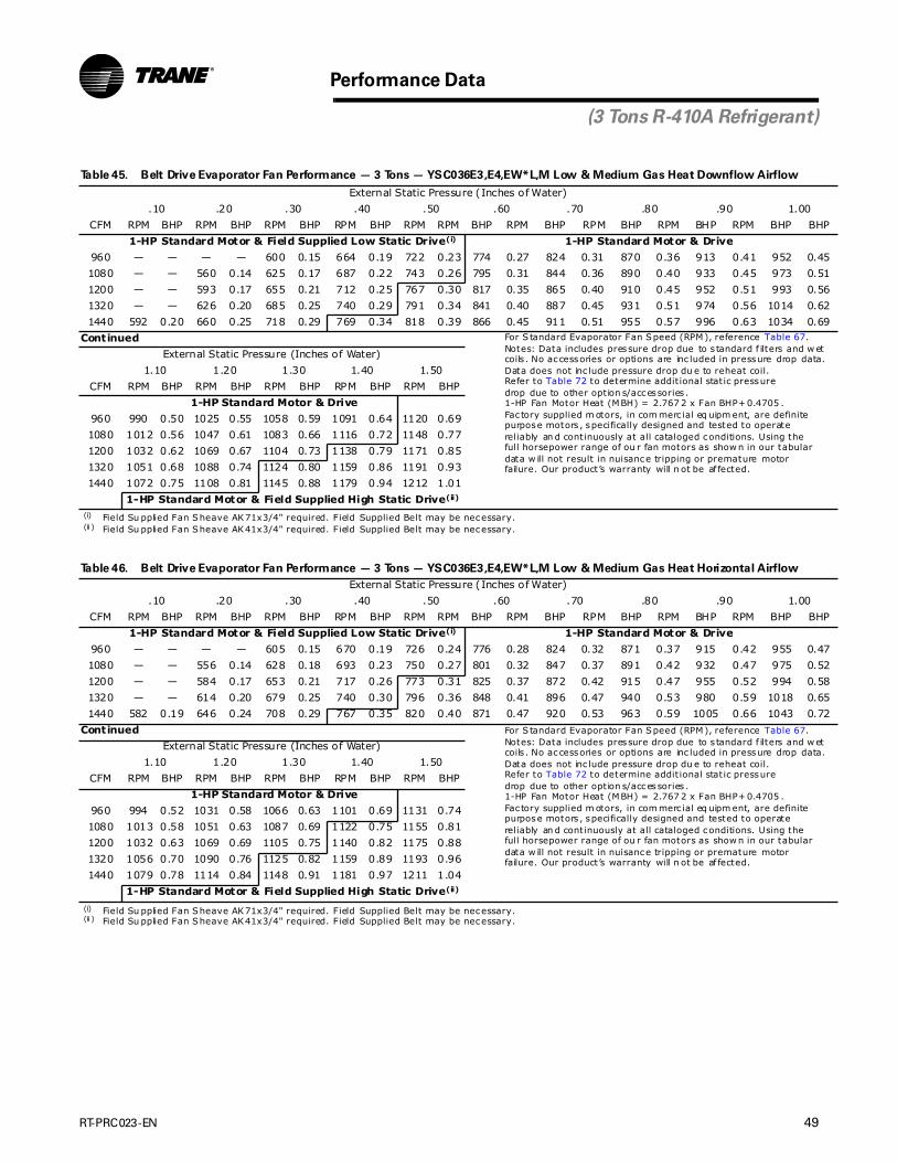
RT-PRC023-EN 49
Performance Data
Table 45. Belt Drive Evaporator Fan Performance — 3 Tons — YSC036E3,E4,EW*L,M Low & Medium Gas Heat Downflow Airflow
External Static Pressure (Inches of Water)
.10 .20 .30 .40 .50 .60 .70 .80 .90 1.00
CFM RPM BHP RPM BHP RPM BHP RPM BHP RPM RPM BHP RPM BHP RPM BHP RPM BHP RPM BHP BHP
1-HP Standard Motor & Field Supplied Low Static Drive(i)
(i) Field Su pplied Fan Sheave AK71x3/4" required. Field Supplied Belt may be necessary.
1-HP Standard Motor & Drive
960 — — — — 600 0.15 664 0.19 722 0.23 774 0.27 824 0.31 870 0.36 913 0.41 952 0.45
1080 — — 560 0.14 625 0.17 687 0.22 743 0.26 795 0.31 844 0.36 890 0.40 933 0.45 973 0.51
1200 — — 593 0.17 655 0.21 712 0.25 767 0.30 817 0.35 865 0.40 910 0.45 952 0.51 993 0.56
1320 — — 626 0.20 685 0.25 740 0.29 791 0.34 841 0.40 887 0.45 931 0.51 974 0.56 1014 0.62
1440 592 0.20 660 0.25 718 0.29 769 0.34 818 0.39 866 0.45 911 0.51 955 0.57 996 0.63 1034 0.69
Continued For S tandard Evaporator Fan Speed (RPM), reference Table 67.Notes: Data includes pressure drop due to s tandard f ilters and w etcoils . No accessories or options are inc luded in pressure drop data.Data does not inc lude pressure drop du e to reheat coil.Refer to Table 72 to determine addit ional static pressuredrop due to other option s/accessories .1-HP Fan Motor Heat (MBH) = 2.767 2 x Fan BHP+ 0.4705 .Fac tory supplied m otors, in com merc ial eq uipm ent, are definitepurpose motors , specifically designed and tested to operate reliably an d continuously at all cataloged conditions. Using thefull horsepower range of ou r fan motors as show n in our tabulardata w ill not result in nuisance tripping or premature motor failure. Our product’s warranty will n ot be af fected.
External Static Pressure (Inches of Water)
1.10 1.20 1.30 1.40 1.50
CFM RPM BHP RPM BHP RPM BHP RPM BHP RPM BHP
1-HP Standard Motor & Drive
960 990 0.50 1025 0.55 1058 0.59 1091 0.64 1120 0.69
1080 1012 0.56 1047 0.61 1083 0.66 1116 0.72 1148 0.77
1200 1032 0.62 1069 0.67 1104 0.73 1138 0.79 1171 0.85
1320 1051 0.68 1088 0.74 1124 0.80 1159 0.86 1191 0.93
1440 1072 0.75 1108 0.81 1145 0.88 1179 0.94 1212 1.01
1-HP Standard Motor & Field Supplied High Static Drive(ii)
(ii ) Field Su pplied Fan Sheave AK41x3/4" required. Field Supplied Belt may be necessary.
Table 46. Belt Drive Evaporator Fan Performance — 3 Tons — YSC036E3,E4,EW*L,M Low & Medium Gas Heat Horizontal Airflow
External Static Pressure (Inches of Water)
.10 .20 .30 .40 .50 .60 .70 .80 .90 1.00
CFM RPM BHP RPM BHP RPM BHP RPM BHP RPM RPM BHP RPM BHP RPM BHP RPM BHP RPM BHP BHP
1-HP Standard Motor & Field Supplied Low Static Drive(i)
(i) Field Su pplied Fan Sheave AK71x3/4" required. Field Supplied Belt may be necessary.
1-HP Standard Motor & Drive
960 — — — — 605 0.15 670 0.19 726 0.24 776 0.28 824 0.32 871 0.37 915 0.42 955 0.47
1080 — — 556 0.14 628 0.18 693 0.23 750 0.27 801 0.32 847 0.37 891 0.42 932 0.47 975 0.52
1200 — — 584 0.17 653 0.21 717 0.26 773 0.31 825 0.37 872 0.42 915 0.47 955 0.52 994 0.58
1320 — — 614 0.20 679 0.25 740 0.30 796 0.36 848 0.41 896 0.47 940 0.53 980 0.59 1018 0.65
1440 582 0.19 646 0.24 708 0.29 767 0.35 820 0.40 871 0.47 920 0.53 963 0.59 1005 0.66 1043 0.72
Continued For S tandard Evaporator Fan Speed (RPM), reference Table 67.Notes: Data includes pressure drop due to s tandard f ilters and w etcoils . No accessories or options are inc luded in pressure drop data.Data does not inc lude pressure drop du e to reheat coil.Refer to Table 72 to determine addit ional static pressuredrop due to other option s/accessories .1-HP Fan Motor Heat (MBH) = 2.767 2 x Fan BHP+ 0.4705 .Fac tory supplied m otors, in com merc ial eq uipm ent, are definitepurpose motors , specifically designed and tested to operate reliably an d continuously at all cataloged conditions. Using thefull horsepower range of ou r fan motors as show n in our tabulardata w ill not result in nuisance tripping or premature motor failure. Our product’s warranty will n ot be af fected.
External Static Pressure (Inches of Water)
1.10 1.20 1.30 1.40 1.50
CFM RPM BHP RPM BHP RPM BHP RPM BHP RPM BHP
1-HP Standard Motor & Drive
960 994 0.52 1031 0.58 1066 0.63 1101 0.69 1131 0.74
1080 1013 0.58 1051 0.63 1087 0.69 1122 0.75 1155 0.81
1200 1032 0.63 1069 0.69 1105 0.75 1140 0.82 1175 0.88
1320 1056 0.70 1090 0.76 1125 0.82 1159 0.89 1193 0.96
1440 1079 0.78 1114 0.84 1148 0.91 1181 0.97 1211 1.04
1-HP Standard Motor & Field Supplied High Static Drive(ii)
(ii ) Field Su pplied Fan Sheave AK41x3/4" required. Field Supplied Belt may be necessary.
(3 Tons R-410A Refrigerant)

50 RT-PRC023-EN
Performance Data
(3 Tons R-410A Refrigerant)
Table 47. Belt Drive Evaporator Fan Performance — 3 Tons — YSC036E3,E4,EW*HH High Gas Heat Downflow Airflow
External Static Pressure (Inches of Water)
.10 .20 .30 .40 .50 .60 .70 .80 .90 1.00
CFM RPM BHP RPM BHP RPM BHP RPM BHP RPM RPM BHP RPM BHP RPM BHP RPM BHP RPM BHP BHP
1-HP Standard Motor & Field Supplied Low Static Drive(i)
(i) Field Su pplied Fan Sheave AK71x3/4" required. Field Supplied Belt may be necessary.
1-HP Standard Motor & Drive
960 — — — — 603 0.15 664 0.19 722 0.24 775 0.28 824 0.33 869 0.37 912 0.42 953 0.47
1080 — — 568 0.14 632 0.18 690 0.23 744 0.27 796 0.32 844 0.37 889 0.42 933 0.47 973 0.53
1200 — — 602 0.18 663 0.22 718 0.27 770 0.31 819 0.36 865 0.42 911 0.47 953 0.53 993 0.58
1320 572 0.17 638 0.22 695 0.26 748 0.31 798 0.36 845 0.41 889 0.47 932 0.53 974 0.58 1015 0.65
1440 611 0.21 674 0.27 729 0.31 779 0.36 827 0.42 872 0.47 915 0.53 957 0.59 997 0.65 1036 0.72
Continued For S tandard Evaporator Fan Speed (RPM), reference Table 67.Notes: Data includes pressure drop due to s tandard f ilters and w etcoils . No accessories or options are inc luded in pressure drop data.Data does not inc lude pressure drop du e to reheat coil.Refer to Table 72 to determine addit ional static pressuredrop due to other option s/accessories .1-HP Fan Motor Heat (MBH) = 2.767 2 x Fan BHP+ 0.4705 .Fac tory supplied m otors, in com merc ial eq uipm ent, are definitepurpose motors , specifically designed and tested to operate reliably an d continuously at all cataloged conditions. Using thefull horsepower range of ou r fan motors as show n in our tabulardata w ill not result in nuisance tripping or premature motor failure. Our product’s warranty will n ot be af fected.
External Static Pressure (Inches of Water)
1.10 1.20 1.30 1.40 1.50
CFM RPM BHP RPM BHP RPM BHP RPM BHP RPM BHP
1-HP Standard Motor & Drive
960 990 0.52 1026 0.58 1060 0.63 1092 0.68 1123 0.73
1080 1011 0.58 1047 0.63 1083 0.69 1115 0.75 1148 0.81
1200 1033 0.64 1069 0.70 1105 0.76 1138 0.82 1170 0.88
1320 1053 0.71 1089 0.77 1124 0.83 1159 0.90 1191 0.96
1440 1074 0.78 1109 0.84 1145 0.91 1178 0.98 1212 1.05
1-HP Standard Motor & Field Supplied High Static Drive(ii)
(ii ) Field Su pplied Fan Sheave AK41x3/4" required. Field Supplied Belt may be necessary.
Table 48. Belt Drive Evaporator Fan Performance — 3 Tons — YSC036E3,E4,EW*HH High Gas Heat Horizontal Airflow
External Static Pressure (Inches of Water)
.10 .20 .30 .40 .50 .60 .70 .80 .90 1.00
CFM RPM BHP RPM BHP RPM BHP RPM BHP RPM RPM BHP RPM BHP RPM BHP RPM BHP RPM BHP BHP
1-HP Standard Motor & Field Supplied Low Static Drive(i)
(i) Field Su pplied Fan Sheave AK71x3/4" required. Field Supplied Belt may be necessary.
1-HP Standard Motor & Drive
960 — — — — 615 0.16 678 0.20 737 0.24 789 0.29 838 0.33 883 0.38 923 0.42 962 0.47
1080 — — 576 0.14 643 0.19 704 0.23 760 0.28 812 0.32 861 0.38 906 0.43 949 0.48 988 0.53
1200 — — 608 0.18 673 0.22 732 0.27 785 0.32 836 0.37 883 0.42 928 0.48 971 0.53 1012 0.59
1320 571 0.17 642 0.22 705 0.26 761 0.31 813 0.37 862 0.42 908 0.48 952 0.53 995 0.59 1034 0.66
1440 609 0.21 677 0.26 737 0.31 791 0.37 841 0.42 889 0.48 934 0.54 977 0.60 1017 0.66 1057 0.72
Continued For S tandard Evaporator Fan Speed (RPM), reference Table 67.Notes: Data includes pressure drop due to s tandard f ilters and w etcoils . No accessories or options are inc luded in pressure drop data.Data does not inc lude pressure drop du e to reheat coil.Refer to Table 72 to determine addit ional static pressuredrop due to other option s/accessories .1-HP Fan Motor Heat (MBH) = 2.767 2 x Fan BHP+ 0.4705 .Fac tory supplied m otors, in com merc ial eq uipm ent, are definitepurpose motors , specifically designed and tested to operate reliably an d continuously at all cataloged conditions. Using thefull horsepower range of ou r fan motors as show n in our tabulardata w ill not result in nuisance tripping or premature motor failure. Our product’s warranty will n ot be af fected.
External Static Pressure (Inches of Water)
1.10 1.20 1.30 1.40 1.50
CFM RPM BHP RPM BHP RPM BHP RPM BHP RPM BHP
1-HP Standard Motor & Drive
960 999 0.52 1034 0.57 1068 0.62 1100 0.67 1132 0.72
1080 1024 0.58 1061 0.64 1094 0.69 1126 0.74 1156 0.79
1200 1050 0.65 1086 0.71 1120 0.77 1153 0.83 1183 0.88
1320 1072 0.72 1109 0.78 1145 0.85 1177 0.91 1209 0.98
1440 1095 0.79 1132 0.86 1167 0.93 1201 1.00 1234 1.07
1-HP Standard Motor & Field Supplied High Static Drive(ii)
(ii ) Field Su pplied Fan Sheave AK41x3/4" required. Field Supplied Belt may be necessary.
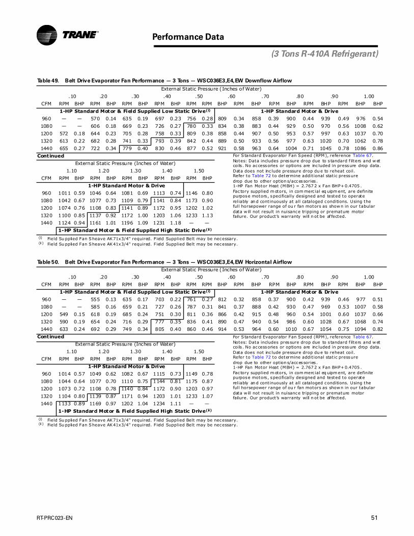
RT-PRC023-EN 51
Performance Data
(3 Tons R-410A Refrigerant)
Table 49. Belt Drive Evaporator Fan Performance — 3 Tons — WSC036E3,E4,EW Downflow Airflow
External Static Pressure (Inches of Water)
.10 .20 .30 .40 .50 .60 .70 .80 .90 1.00
CFM RPM BHP RPM BHP RPM BHP RPM BHP RPM RPM BHP RPM BHP RPM BHP RPM BHP RPM BHP BHP
1-HP Standard Motor & Field Supplied Low Static Drive(i)
(i) Field Su pplied Fan Sheave AK71x3/4" required. Field Supplied Belt may be necessary.
1-HP Standard Motor & Drive
960 — — 570 0.14 635 0.19 697 0.23 756 0.28 809 0.34 858 0.39 900 0.44 939 0.49 976 0.54
1080 — — 606 0.18 669 0.23 726 0.27 780 0.33 834 0.38 883 0.44 929 0.50 970 0.56 1008 0.62
1200 572 0.18 644 0.23 705 0.28 758 0.33 809 0.38 858 0.44 907 0.50 953 0.57 997 0.63 1037 0.70
1320 613 0.22 682 0.28 741 0.33 793 0.39 842 0.44 889 0.50 933 0.56 977 0.63 1020 0.70 1062 0.78
1440 655 0.27 722 0.34 779 0.40 830 0.46 877 0.52 921 0.58 963 0.64 1004 0.71 1045 0.78 1086 0.86
Continued For S tandard Evaporator Fan Speed (RPM), reference Table 67.Notes: Data includes pressure drop due to s tandard f ilters and w etcoils . No accessories or options are inc luded in pressure drop data.Data does not inc lude pressure drop du e to reheat coil.Refer to Table 72 to determine addit ional static pressuredrop due to other option s/accessories .1-HP Fan Motor Heat (MBH) = 2.767 2 x Fan BHP+ 0.4705 .Fac tory supplied m otors, in com merc ial eq uipm ent, are definitepurpose motors , specifically designed and tested to operate reliably an d continuously at all cataloged conditions. Using thefull horsepower range of ou r fan motors as show n in our tabulardata w ill not result in nuisance tripping or premature motor failure. Our product’s warranty will n ot be af fected.
External Static Pressure (Inches of Water)
1.10 1.20 1.30 1.40 1.50
CFM RPM BHP RPM BHP RPM BHP RPM BHP RPM BHP
1-HP Standard Motor & Drive
960 1011 0.59 1046 0.64 1081 0.69 1113 0.74 1146 0.80
1080 1042 0.67 1077 0.73 1109 0.79 1141 0.84 1173 0.90
1200 1074 0.76 1108 0.83 1141 0.89 1172 0.95 1202 1.02
1320 1100 0.85 1137 0.92 1172 1.00 1203 1.06 1233 1.13
1440 1124 0.94 1161 1.01 1196 1.09 1231 1.18 — —
1-HP Standard Motor & Field Supplied High Static Drive(ii)
(ii ) Field Su pplied Fan Sheave AK41x3/4" required. Field Supplied Belt may be necessary.
Table 50. Belt Drive Evaporator Fan Performance — 3 Tons — WSC036E3,E4,EW Horizontal Airflow
External Static Pressure (Inches of Water)
.10 .20 .30 .40 .50 .60 .70 .80 .90 1.00
CFM RPM BHP RPM BHP RPM BHP RPM BHP RPM RPM BHP RPM BHP RPM BHP RPM BHP RPM BHP BHP
1-HP Standard Motor & Field Supplied Low Static Drive(i)
(i) Field Su pplied Fan Sheave AK71x3/4" required. Field Supplied Belt may be necessary.
1-HP Standard Motor & Drive
960 — — 555 0.13 635 0.17 703 0.22 761 0.27 812 0.32 858 0.37 900 0.42 939 0.46 977 0.51
1080 — — 585 0.16 659 0.21 727 0.26 787 0.31 841 0.37 888 0.42 930 0.47 969 0.53 1007 0.58
1200 549 0.15 618 0.19 685 0.24 751 0.30 811 0.36 866 0.42 915 0.48 960 0.54 1001 0.60 1037 0.66
1320 590 0.19 654 0.24 716 0.29 777 0.35 836 0.41 890 0.47 940 0.54 986 0.60 1028 0.67 1068 0.74
1440 633 0.24 692 0.29 749 0.34 805 0.40 860 0.46 914 0.53 964 0.60 1010 0.67 1054 0.75 1094 0.82
Continued For S tandard Evaporator Fan Speed (RPM), reference Table 67.Notes: Data includes pressure drop due to s tandard f ilters and w etcoils . No accessories or options are inc luded in pressure drop data.Data does not inc lude pressure drop du e to reheat coil.Refer to Table 72 to determine addit ional static pressuredrop due to other option s/accessories .1-HP Fan Motor Heat (MBH) = 2.767 2 x Fan BHP+ 0.4705 .Fac tory supplied m otors, in com merc ial eq uipm ent, are definitepurpose motors , specifically designed and tested to operate reliably an d continuously at all cataloged conditions. Using thefull horsepower range of ou r fan motors as show n in our tabulardata w ill not result in nuisance tripping or premature motor failure. Our product’s warranty will n ot be af fected.
External Static Pressure (Inches of Water)
1.10 1.20 1.30 1.40 1.50
CFM RPM BHP RPM BHP RPM BHP RPM BHP RPM BHP
1-HP Standard Motor & Drive
960 1014 0.57 1049 0.62 1082 0.67 1115 0.73 1149 0.78
1080 1044 0.64 1077 0.70 1110 0.75 1144 0.81 1175 0.87
1200 1073 0.72 1108 0.78 1140 0.84 1172 0.90 1203 0.97
1320 1104 0.80 1139 0.87 1171 0.94 1203 1.01 1233 1.07
1440 1133 0.89 1169 0.97 1202 1.04 1234 1.11 — —
1-HP Standard Motor & Field Supplied High Static Drive(ii)
(ii ) Field Su pplied Fan Sheave AK41x3/4" required. Field Supplied Belt may be necessary.
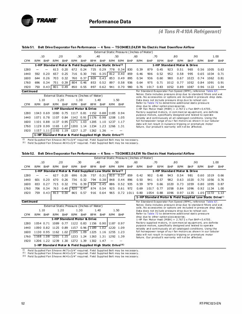
52 RT-PRC023-EN
Performance Data
(4 Tons R-410A Refrigerant)
Table 51. Belt Drive Evaporator Fan Performance — 4 Tons — TSC048E3,E4,EW No Electric Heat Downflow Airflow
External Static Pressure (Inches of Water)
.10 .20 .30 .40 .50 .60 .70 .80 .90 1.00
CFM RPM BHP RPM BHP RPM BHP RPM BHP RPM RPM BHP RPM BHP RPM BHP RPM BHP RPM BHP BHP
1-HP Standard Motor & Field Supplied Low Static Drive(i)
(i) Field Su pplied Fan Sheave AK71x3/4" required. Field Supplied Belt may be necessary.
1-HP Standard Motor & Drive
1280 — — 613 0.20 672 0.24 725 0.29 778 0.34 830 0.39 879 0.45 923 0.51 965 0.56 1005 0.63
1440 592 0.20 657 0.25 716 0.30 765 0.35 812 0.40 859 0.46 906 0.52 952 0.58 995 0.65 1034 0.71
1600 644 0.26 703 0.32 760 0.37 809 0.43 853 0.49 895 0.54 936 0.60 980 0.67 1023 0.74 1062 0.81
1760 696 0.34 751 0.39 804 0.46 853 0.52 897 0.58 936 0.64 975 0.71 1012 0.77 1052 0.84 1091 0.91
1920 750 0.43 801 0.49 850 0.55 897 0.62 941 0.70 980 0.76 1017 0.83 1052 0.89 1087 0.96 1122 1.04
Continued For S tandard Evaporator Fan Speed (RPM), reference Table 67.Notes: Data includes pressure drop due to s tandard f ilters and w etcoils . No accessories or options are inc luded in pressure drop data.Data does not inc lude pressure drop du e to reheat coil.Refer to Table 72 to determine addit ional static pressuredrop due to other option s/accessories .1-HP Fan Motor Heat (MBH) = 2.767 2 x Fan BHP+ 0.4705 .Fac tory supplied m otors, in com merc ial eq uipm ent, are definitepurpose motors , specifically designed and tested to operate reliably an d continuously at all cataloged conditions. Using thefull horsepower range of ou r fan motors as show n in our tabulardata w ill not result in nuisance tripping or premature motor failure. Our product’s warranty will n ot be af fected.
External Static Pressure (Inches of Water)
1.10 1.20 1.30 1.40 1.50
CFM RPM BHP RPM BHP RPM BHP RPM BHP RPM BHP
1-HP Standard Motor & Drive
1280 1043 0.69 1080 0.75 1117 0.81 1152 0.88 1185 0.94
1440 1071 0.78 1107 0.84 1142 0.91 1176 0.98 1208 1.05
1600 1101 0.88 1137 0.95 1171 1.03 1205 1.10 1237 1.17
1760 1129 0.99 1165 1.07 1200 1.14 1234 1.23 1266 1.31
1920 1157 1.11 1193 1.19 1227 1.27 1262 1.36 — —
1-HP Standard Motor & Field Supplied High Static Drive(ii)
(ii ) Field Su pplied Fan Sheave AK41x3/4" required. Field Supplied Belt may be necessary.
Table 52. Belt Drive Evaporator Fan Performance — 4 Tons — TSC048E3,E4,EW No Electric Heat Horizontal Airflow
External Static Pressure (Inches of Water)
.10 .20 .30 .40 .50 .60 .70 .80 .90 1.00
CFM RPM BHP RPM BHP RPM BHP RPM BHP RPM RPM BHP RPM BHP RPM BHP RPM BHP RPM BHP BHP
1-HP Standard Motor & Field Supplied Low Static Drive(i)
(i) Field Su pplied Fan Sheave AK71x3/4" required. Field Supplied Belt may be necessary.
1-HP Standard Motor & Drive
1280 — — 627 0.20 696 0.26 757 0.31 810 0.37 859 0.42 902 0.48 943 0.54 981 0.60 1019 0.66
1440 601 0.20 670 0.26 736 0.32 794 0.38 848 0.44 896 0.50 941 0.57 982 0.63 1020 0.70 1056 0.76
1600 653 0.27 715 0.32 776 0.39 834 0.45 886 0.52 935 0.59 979 0.66 1020 0.73 1059 0.80 1095 0.87
1760 706 0.34 763 0.40 820 0.47 874 0.54 925 0.61 972 0.69 1017 0.77 1058 0.84 1096 0.92 1134 1.00
1920 759 0.43 813 0.50 865 0.57 916 0.64 965 0.72 1011 0.80 1054 0.88 1096 0.97 1135 1.05 1172 1.13
1-HP Standard Motor & Field Supplied Low Static Drive(i i)
(ii ) Field Su pplied Fan Sheave AK41x3/4" required. Field Supplied Belt may be necessary.
Continued For S tandard Evaporator Fan Speed (RPM), reference Table 67.Notes: Data includes pressure drop due to s tandard f ilters and w etcoils . No accessories or options are inc luded in pressure drop data.Data does not inc lude pressure drop du e to reheat coil.Refer to Table 72 to determine addit ional static pressuredrop due to other option s/accessories .1-HP Fan Motor Heat (MBH) = 2.767 2 x Fan BHP+ 0.4705 .Fac tory supplied m otors, in com merc ial eq uipm ent, are definitepurpose motors , specifically designed and tested to operate reliably an d continuously at all cataloged conditions. Using thefull horsepower range of ou r fan motors as show n in our tabulardata w ill not result in nuisance tripping or premature motor failure. Our product’s warranty will n ot be af fected.
External Static Pressure (Inches of Water)
1.10 1.20 1.30 1.40 1.50
CFM RPM BHP RPM BHP RPM BHP RPM BHP RPM BHP
1-HP Standard Motor & Drive
1280 1054 0.71 1089 0.77 1122 0.83 1156 0.90 1187 0.97
1440 1090 0.82 1125 0.89 1157 0.96 1189 1.02 1220 1.09
1600 1130 0.95 1162 1.02 1195 1.09 1225 1.16 1255 1.23
1760 1168 1.08 1201 1.15 1233 1.24 1263 1.31 1292 1.39
1920 1206 1.22 1239 1.30 1272 1.39 1302 1.47 — —
1-HP Standard Motor & Field Supplied High Static Drive(iii)
(ii i) Field Su pplied Fan Sheave AK41x3/4" required. Field Supplied Belt may be necessary.
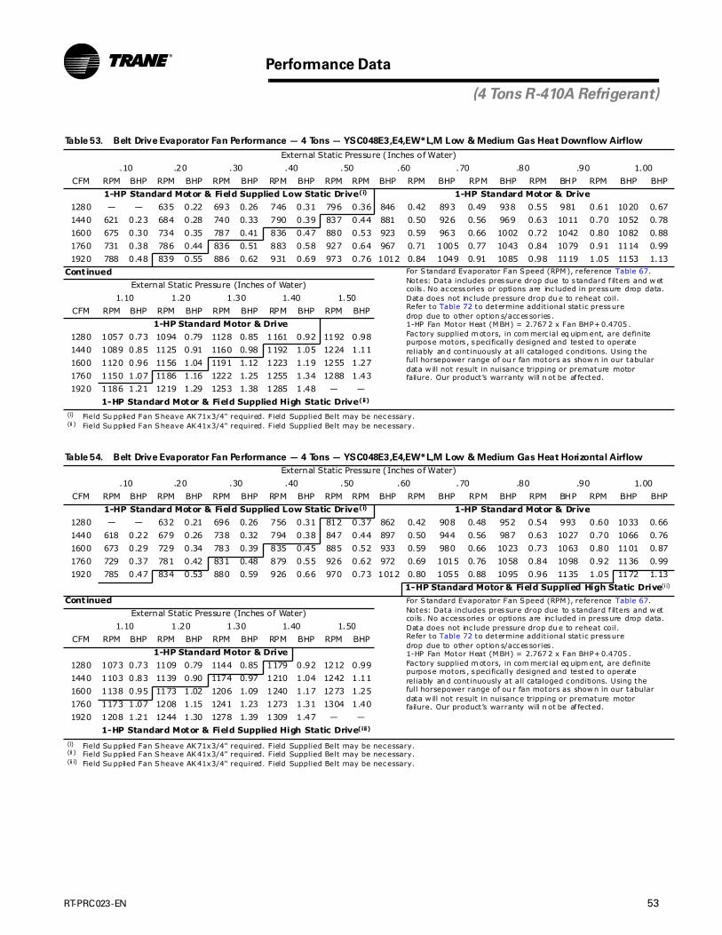
RT-PRC023-EN 53
Performance Data
(4 Tons R-410A Refrigerant)
Table 53. Belt Drive Evaporator Fan Performance — 4 Tons — YSC048E3,E4,EW*L,M Low & Medium Gas Heat Downflow Airflow
External Static Pressure (Inches of Water)
.10 .20 .30 .40 .50 .60 .70 .80 .90 1.00
CFM RPM BHP RPM BHP RPM BHP RPM BHP RPM RPM BHP RPM BHP RPM BHP RPM BHP RPM BHP BHP
1-HP Standard Motor & Field Supplied Low Static Drive(i)
(i) Field Su pplied Fan Sheave AK71x3/4" required. Field Supplied Belt may be necessary.
1-HP Standard Motor & Drive
1280 — — 635 0.22 693 0.26 746 0.31 796 0.36 846 0.42 893 0.49 938 0.55 981 0.61 1020 0.67
1440 621 0.23 684 0.28 740 0.33 790 0.39 837 0.44 881 0.50 926 0.56 969 0.63 1011 0.70 1052 0.78
1600 675 0.30 734 0.35 787 0.41 836 0.47 880 0.53 923 0.59 963 0.66 1002 0.72 1042 0.80 1082 0.88
1760 731 0.38 786 0.44 836 0.51 883 0.58 927 0.64 967 0.71 1005 0.77 1043 0.84 1079 0.91 1114 0.99
1920 788 0.48 839 0.55 886 0.62 931 0.69 973 0.76 1012 0.84 1049 0.91 1085 0.98 1119 1.05 1153 1.13
Continued For S tandard Evaporator Fan Speed (RPM), reference Table 67.Notes: Data includes pressure drop due to s tandard f ilters and w etcoils . No accessories or options are inc luded in pressure drop data.Data does not inc lude pressure drop du e to reheat coil.Refer to Table 72 to determine addit ional static pressuredrop due to other option s/accessories .1-HP Fan Motor Heat (MBH) = 2.767 2 x Fan BHP+ 0.4705 .Fac tory supplied m otors, in com merc ial eq uipm ent, are definitepurpose motors , specifically designed and tested to operate reliably an d continuously at all cataloged conditions. Using thefull horsepower range of ou r fan motors as show n in our tabulardata w ill not result in nuisance tripping or premature motor failure. Our product’s warranty will n ot be af fected.
External Static Pressure (Inches of Water)
1.10 1.20 1.30 1.40 1.50
CFM RPM BHP RPM BHP RPM BHP RPM BHP RPM BHP
1-HP Standard Motor & Drive
1280 1057 0.73 1094 0.79 1128 0.85 1161 0.92 1192 0.98
1440 1089 0.85 1125 0.91 1160 0.98 1192 1.05 1224 1.11
1600 1120 0.96 1156 1.04 1191 1.12 1223 1.19 1255 1.27
1760 1150 1.07 1186 1.16 1222 1.25 1255 1.34 1288 1.43
1920 1186 1.21 1219 1.29 1253 1.38 1285 1.48 — —
1-HP Standard Motor & Field Supplied High Static Drive(ii)
(ii ) Field Su pplied Fan Sheave AK41x3/4" required. Field Supplied Belt may be necessary.
Table 54. Belt Drive Evaporator Fan Performance — 4 Tons — YSC048E3,E4,EW*L,M Low & Medium Gas Heat Horizontal Airflow
External Static Pressure (Inches of Water)
.10 .20 .30 .40 .50 .60 .70 .80 .90 1.00
CFM RPM BHP RPM BHP RPM BHP RPM BHP RPM RPM BHP RPM BHP RPM BHP RPM BHP RPM BHP BHP
1-HP Standard Motor & Field Supplied Low Static Drive(i)
(i) Field Su pplied Fan Sheave AK71x3/4" required. Field Supplied Belt may be necessary.
1-HP Standard Motor & Drive
1280 — — 632 0.21 696 0.26 756 0.31 812 0.37 862 0.42 908 0.48 952 0.54 993 0.60 1033 0.66
1440 618 0.22 679 0.26 738 0.32 794 0.38 847 0.44 897 0.50 944 0.56 987 0.63 1027 0.70 1066 0.76
1600 673 0.29 729 0.34 783 0.39 835 0.45 885 0.52 933 0.59 980 0.66 1023 0.73 1063 0.80 1101 0.87
1760 729 0.37 781 0.42 831 0.48 879 0.55 926 0.62 972 0.69 1015 0.76 1058 0.84 1098 0.92 1136 0.99
1920 785 0.47 834 0.53 880 0.59 926 0.66 970 0.73 1012 0.80 1055 0.88 1095 0.96 1135 1.05 1172 1.13
1-HP Standard Motor & Field Supplied High Static Drive(i i)
(ii ) Field Su pplied Fan Sheave AK41x3/4" required. Field Supplied Belt may be necessary.
Continued For S tandard Evaporator Fan Speed (RPM), reference Table 67.Notes: Data includes pressure drop due to s tandard f ilters and w etcoils . No accessories or options are inc luded in pressure drop data.Data does not inc lude pressure drop du e to reheat coil.Refer to Table 72 to determine addit ional static pressuredrop due to other option s/accessories .1-HP Fan Motor Heat (MBH) = 2.767 2 x Fan BHP+ 0.4705 .Fac tory supplied m otors, in com merc ial eq uipm ent, are definitepurpose motors , specifically designed and tested to operate reliably an d continuously at all cataloged conditions. Using thefull horsepower range of ou r fan motors as show n in our tabulardata w ill not result in nuisance tripping or premature motor failure. Our product’s warranty will n ot be af fected.
External Static Pressure (Inches of Water)
1.10 1.20 1.30 1.40 1.50
CFM RPM BHP RPM BHP RPM BHP RPM BHP RPM BHP
1-HP Standard Motor & Drive
1280 1073 0.73 1109 0.79 1144 0.85 1179 0.92 1212 0.99
1440 1103 0.83 1139 0.90 1174 0.97 1210 1.04 1242 1.11
1600 1138 0.95 1173 1.02 1206 1.09 1240 1.17 1273 1.25
1760 1173 1.07 1208 1.15 1241 1.23 1273 1.31 1304 1.40
1920 1208 1.21 1244 1.30 1278 1.39 1309 1.47 — —
1-HP Standard Motor & Field Supplied High Static Drive(iii)
(ii i) Field Su pplied Fan Sheave AK41x3/4" required. Field Supplied Belt may be necessary.

54 RT-PRC023-EN
Performance Data
(4 Tons R-410A Refrigerant)
Table 55. Belt Drive Evaporator Fan Performance — 4 Tons — YSC048E3,E4,EW*HH High Gas Heat Downflow Airflow
External Static Pressure (Inches of Water)
.10 .20 .30 .40 .50 .60 .70 .80 .90 1.00
CFM RPM BHP RPM BHP RPM BHP RPM BHP RPM RPM BHP RPM BHP RPM BHP RPM BHP RPM BHP BHP
1-HP Standard Motor & Field Supplied Low Static Drive(i)
(i) Field Su pplied Fan Sheave AK71x3/4" required. Field Supplied Belt may be necessary.
1-HP Standard Motor & Drive
1280 583 0.17 647 0.21 705 0.26 758 0.31 809 0.36 859 0.41 907 0.47 951 0.53 993 0.59 1033 0.65
1440 639 0.23 699 0.28 753 0.33 803 0.38 851 0.43 895 0.49 940 0.55 983 0.61 1025 0.68 1064 0.74
1600 696 0.30 752 0.36 803 0.41 850 0.47 895 0.53 937 0.58 979 0.65 1019 0.71 1058 0.78 1097 0.85
1760 754 0.39 807 0.45 855 0.51 900 0.57 942 0.63 982 0.70 1021 0.76 1059 0.83 1096 0.90 1132 0.97
1920 813 0.49 862 0.56 908 0.63 951 0.69 991 0.76 1029 0.82 1067 0.89 1102 0.96 1138 1.04 1172 1.11
1-HP Standard Motor & Field Supplied High Static Drive(i i)
(ii ) Field Su pplied Fan Sheave AK41x3/4" required. Field Supplied Belt may be necessary.
Continued For S tandard Evaporator Fan Speed (RPM), reference Table 67.Notes: Data includes pressure drop due to s tandard f ilters and w etcoils . No accessories or options are inc luded in pressure drop data.Data does not inc lude pressure drop du e to reheat coil.Refer to Table 72 to determine addit ional static pressuredrop due to other option s/accessories .1-HP Fan Motor Heat (MBH) = 2.767 2 x Fan BHP+ 0.4705 .Fac tory supplied m otors, in com merc ial eq uipm ent, are definitepurpose motors , specifically designed and tested to operate reliably an d continuously at all cataloged conditions. Using thefull horsepower range of ou r fan motors as show n in our tabulardata w ill not result in nuisance tripping or premature motor failure. Our product’s warranty will n ot be af fected.
External Static Pressure (Inches of Water)
1.10 1.20 1.30 1.40 1.50
CFM RPM BHP RPM BHP RPM BHP RPM BHP RPM BHP
1-HP Standard Motor & Drive
1280 1071 0.71 1105 0.77 1139 0.83 1173 0.89 1202 0.94
1440 1103 0.81 1139 0.88 1174 0.94 1207 1.01 1238 1.08
1600 1135 0.92 1171 0.99 1207 1.07 1239 1.14 1271 1.21
1760 1167 1.04 1203 1.12 1238 1.20 1271 1.28 1303 1.36
1920 1204 1.19 1238 1.27 1271 1.35 1303 1.43 — —
1-HP Standard Motor & Field Supplied High Static Drive(iii)
(ii i) Field Su pplied Fan Sheave AK41x3/4" required. Field Supplied Belt may be necessary.
Table 56. Belt Drive Evaporator Fan Performance — 4 Tons — YSC048E3,E4,EW*HH High Gas Heat Horizontal Airflow
External Static Pressure (Inches of Water)
.10 .20 .30 .40 .50 .60 .70 .80 .90 1.00
CFM RPM BHP RPM BHP RPM BHP RPM BHP RPM RPM BHP RPM BHP RPM BHP RPM BHP RPM BHP BHP
1-HP Standard Motor & Field Supplied Low Static Drive(i)
(i) Field Su pplied Fan Sheave AK71x3/4" required. Field Supplied Belt may be necessary.
1-HP Standard Motor & Drive
1280 583 0.18 653 0.23 715 0.28 772 0.33 825 0.39 874 0.45 919 0.51 962 0.57 1002 0.64 1041 0.70
1440 637 0.24 703 0.29 762 0.35 815 0.41 866 0.47 913 0.53 958 0.60 1000 0.67 1040 0.74 1077 0.81
1600 693 0.31 755 0.37 810 0.44 861 0.50 909 0.56 955 0.63 998 0.70 1039 0.78 1078 0.85 1115 0.92
1760 749 0.40 808 0.47 861 0.54 909 0.61 954 0.68 997 0.75 1039 0.82 1079 0.90 1117 0.98 1154 1.06
1920 807 0.50 861 0.58 912 0.66 959 0.73 1002 0.81 1043 0.88 1083 0.96 1121 1.04 1158 1.12 1194 1.21
1-HP Standard Motor & Field Supplied High Static Drive(i i)
(ii ) Field Su pplied Fan Sheave AK41x3/4" required. Field Supplied Belt may be necessary.
Continued For S tandard Evaporator Fan Speed (RPM), reference Table 67.Notes: Data includes pressure drop due to s tandard f ilters and w etcoils . No accessories or options are inc luded in pressure drop data.Data does not inc lude pressure drop du e to reheat coil.Refer to Table 72 to determine addit ional static pressuredrop due to other option s/accessories .1-HP Fan Motor Heat (MBH) = 2.767 2 x Fan BHP+ 0.4705 .Fac tory supplied m otors, in com merc ial eq uipm ent, are definitepurpose motors , specifically designed and tested to operate reliably an d continuously at all cataloged conditions. Using thefull horsepower range of ou r fan motors as show n in our tabulardata w ill not result in nuisance tripping or premature motor failure. Our product’s warranty will n ot be af fected.
External Static Pressure (Inches of Water)
1.10 1.20 1.30 1.40 1.50
CFM RPM BHP RPM BHP RPM BHP RPM BHP RPM BHP
1-HP Standard Motor & Drive
1280 1079 0.76 1114 0.83 1149 0.89 1181 0.95 1213 1.02
1440 1114 0.88 1148 0.95 1182 1.02 1216 1.09 1248 1.16
1600 1151 1.00 1186 1.08 1218 1.16 1251 1.24 1281 1.31
1760 1189 1.14 1224 1.22 1256 1.31 1287 1.39 1319 1.48
1920 1229 1.29 1263 1.38 1295 1.47 — — — —
1-HP Standard Motor & Field Supplied High Static Drive(iii)
(ii i) Field Su pplied Fan Sheave AK41x3/4" required. Field Supplied Belt may be necessary.

RT-PRC023-EN 55
Performance Data
(4 Tons R-410A Refrigerant)
Table 57. Belt Drive Evaporator Fan Performance — 4 Tons — WSC048E3,E4,EW Downflow Airflow
External Static Pressure (Inches of Water)
.10 .20 .30 .40 .50 .60 .70 .80 .90 1.00
CFM RPM BHP RPM BHP RPM BHP RPM BHP RPM RPM BHP RPM BHP RPM BHP RPM BHP RPM BHP BHP
1-HP Standard Motor & Field Supplied Low Static Drive(i)
(i) Field Su pplied Fan Sheave AK71x3/4" required. Field Supplied Belt may be necessary.
1-HP Standard Motor & Drive
1280 — — 613 0.20 672 0.24 725 0.29 778 0.34 830 0.39 879 0.45 923 0.51 965 0.56 1005 0.63
1440 592 0.20 657 0.25 716 0.30 765 0.35 812 0.40 859 0.46 906 0.52 952 0.58 995 0.65 1034 0.71
1600 644 0.26 703 0.32 760 0.37 809 0.43 853 0.49 895 0.54 936 0.60 980 0.67 1023 0.74 1062 0.81
1760 696 0.34 751 0.39 804 0.46 853 0.52 897 0.58 936 0.64 975 0.71 1012 0.77 1052 0.84 1091 0.91
1920 750 0.43 801 0.49 850 0.55 897 0.62 941 0.70 980 0.76 1017 0.83 1052 0.89 1087 0.96 1122 1.04
Continued For Standard Evaporator Fan Speed (RPM), reference Table 67.Notes: Data inc ludes pressure drop due to standard filters an d wetcoils. No accessories or options are included in pressure drop data.Data does not include pressure drop due to reheat coil.Refer to Table 72 to determine additional s tatic pressu redrop due to other options/accessories.1-HP Fan Motor Heat (MBH) = 2.7672 x Fan BHP+0.4705.Factory supplied motors , in commercial equipment, are def initepurpose motors, sp ec ifically des igned and tested to operate reliably and continuou sly at all cataloged condit ion s. Us in g th efu ll horsepow er range of our fan motors as shown in our tabulardata will not result in nuisance tripping or prem ature m otor failure. Our produc t’s warran ty will not be affected.
External Static Pressure (Inches of Water)
1.10 1.20 1.30 1.40 1.50
CFM RPM BHP RPM BHP RPM BHP RPM BHP RPM BHP
1-HP Standard Motor & Drive
1280 1043 0.69 1080 0.75 1117 0.81 1152 0.88 1185 0.94
1440 1071 0.78 1107 0.84 1142 0.91 1176 0.98 1208 1.05
1600 1101 0.88 1137 0.95 1171 1.03 1205 1.10 1237 1.17
1760 1129 0.99 1165 1.07 1200 1.14 1234 1.23 1266 1.31
1920 1157 1.11 1193 1.19 1227 1.27 1262 1.36 — —
1-HP Standard Motor & Field Supplied High Static Drive(ii)
(ii ) Field Su pplied Fan Sheave AK41x3/4" required. Field Supplied Belt may be necessary.
Table 58. Belt Drive Evaporator Fan Performance — 4 Tons — WSC048E3,E4,EW Horizontal Airflow
External Static Pressure (Inches of Water)
.10 .20 .30 .40 .50 .60 .70 .80 .90 1.00
CFM RPM BHP RPM BHP RPM BHP RPM BHP RPM RPM BHP RPM BHP RPM BHP RPM BHP RPM BHP BHP
1-HP Standard Motor & Field Supplied Low Static Drive(i)
(i) Field Su pplied Fan Sheave AK71x3/4" required. Field Supplied Belt may be necessary.
1-HP Standard Motor & Drive
1280 — — 627 0.20 696 0.26 757 0.31 810 0.37 859 0.42 902 0.48 943 0.54 981 0.60 1019 0.66
1440 601 0.20 670 0.26 736 0.32 794 0.38 848 0.44 896 0.50 941 0.57 982 0.63 1020 0.70 1056 0.76
1600 653 0.27 715 0.32 776 0.39 834 0.45 886 0.52 935 0.59 979 0.66 1020 0.73 1059 0.80 1095 0.87
1760 706 0.34 763 0.40 820 0.47 874 0.54 925 0.61 972 0.69 1017 0.77 1058 0.84 1096 0.92 1134 1.00
1920 759 0.43 813 0.50 865 0.57 916 0.64 965 0.72 1011 0.80 1054 0.88 1096 0.97 1135 1.05 1172 1.13
1-HP Standard Motor & Field Supplied High Static Drive( ii )
(ii ) Field Su pplied Fan Sheave AK41x3/4" required. Field Supplied Belt may be necessary.
Continued For Standard Evaporator Fan Speed (RPM), reference Table 67.Notes: Data inc ludes pressure drop due to standard filters an d wetcoils. No accessories or options are included in pressure drop data.Data does not include pressure drop due to reheat coil.Refer to Table 72 to determine additional s tatic pressu redrop due to other options/accessories.1-HP Fan Motor Heat (MBH) = 2.7672 x Fan BHP+0.4705.Factory supplied motors , in commercial equipment, are def initepurpose motors, sp ec ifically des igned and tested to operate reliably and continuou sly at all cataloged condit ion s. Us in g th efu ll horsepow er range of our fan motors as shown in our tabulardata will not result in nuisance tripping or prem ature m otor failure. Our produc t’s warran ty will not be affected.
External Static Pressure (Inches of Water)
1.10 1.20 1.30 1.40 1.50
CFM RPM BHP RPM BHP RPM BHP RPM BHP RPM BHP
1-HP Standard Motor & Drive
1280 1054 0.71 1089 0.77 1122 0.83 1156 0.90 1187 0.97
1440 1090 0.82 1125 0.89 1157 0.96 1189 1.02 1220 1.09
1600 1130 0.95 1162 1.02 1195 1.09 1225 1.16 1255 1.23
1760 1168 1.08 1201 1.15 1233 1.24 1263 1.31 1292 1.39
1920 1206 1.22 1239 1.30 1272 1.39 1302 1.47 — —
1-HP Standard Motor & Field Supplied High Static Drive(iii)
(ii i) Field Su pplied Fan Sheave AK41x3/4" required. Field Supplied Belt may be necessary.

56 RT-PRC023-EN
Performance Data
(5 Tons R-410A Refrigerant)
Table 59. Belt Drive Evaporator Fan Performance — 5 Tons — TSC060E3,E4,EW No Electric Heat Downflow Airflow
External Static Pressure (Inches of Water)
.10 .20 .30 .40 .50 .60 .70 .80 .90 1.00
CFM RPM BHP RPM BHP RPM BHP RPM BHP RPM RPM BHP RPM BHP RPM BHP RPM BHP RPM BHP BHP
1-HP Standard Motor & Field Supplied Low Static Drive(i)
(i) Field Su pplied Fan Sheave AK71x3/4" required. Field Supplied Belt may be necessary.
1-HP Standard Motor & Drive
1600 — — 697 0.31 751 0.37 800 0.42 846 0.48 888 0.53 929 0.59 967 0.64 1005 0.71 1041 0.77
1800 704 0.35 758 0.41 808 0.47 854 0.53 898 0.59 938 0.66 977 0.72 1015 0.78 1050 0.85 1085 0.91
2000 771 0.46 820 0.53 866 0.60 910 0.67 951 0.73 991 0.80 1028 0.87 1064 0.94 1098 1.01 1131 1.08
2200 838 0.60 883 0.68 926 0.75 968 0.83 1007 0.90 1044 0.97 1081 1.05 1115 1.12 1148 1.20 1180 1.28
2400 906 0.77 948 0.85 989 0.93 1027 1.01 1065 1.09 1101 1.17 1135 1.25 1168 1.34 1200 1.42 1232 1.50
Continued For Standard Evaporator Fan Speed (RPM), reference Table 101.Notes: Data inc ludes pressure drop due to standard filters an d wetcoils. No accessories or options are included in pressure drop data.Data does not include pressure drop due to reheat coil.Refer to Table 10 6 to determine addit ional s tatic pressuredrop due to other options/accessories.1-HP Fan Motor Heat (MBH) = 2.7672 x Fan BHP+0.4705.Factory supplied motors , in commercial equipment, are def initepurpose motors, sp ec ifically des igned and tested to operate reliably and continuou sly at all cataloged condit ion s. Us in g th efu ll horsepow er range of our fan motors as shown in our tabulardata will not result in nuisance tripping or prem ature m otor failure. Our produc t’s warran ty will not be affected.
External Static Pressure (Inches of Water)
1.10 1.20 1.30 1.40 1.50
CFM RPM BHP RPM BHP RPM BHP RPM BHP RPM BHP
1-HP Standard Motor & Drive
1600 1075 0.83 1110 0.90 1142 0.96 1176 1.03 1208 1.10
1800 1118 0.98 1151 1.05 1182 1.12 1212 1.19 1243 1.26
2000 1163 1.15 1194 1.22 1225 1.30 1255 1.37 1283 1.45
2200 1211 1.35 1241 1.43 — — — — — —
2400 — — — — — — — — — —
1-HP Standard Motor & Field Supplied High Static Drive(ii)
(ii ) Field Su pplied Fan Sheave AK41x3/4" required. Field Supplied Belt may be necessary.
Table 60. Belt Drive Evaporator Fan Performance — 5 Tons — TSC060E3,E4,EW No Electric Heat Horizontal Airflow
External Static Pressure (Inches of Water)
.10 .20 .30 .40 .50 .60 .70 .80 .90 1.00
CFM RPM BHP RPM BHP RPM BHP RPM BHP RPM RPM BHP RPM BHP RPM BHP RPM BHP RPM BHP BHP
1-HP Standard Motor & Field Supplied Low Static Drive(i)
(i) Field Su pplied Fan Sheave AK71x3/4" required. Field Supplied Belt may be necessary.
1-HP Standard Motor & Drive
1600 — — 707 0.31 763 0.37 815 0.42 862 0.48 905 0.54 946 0.60 984 0.65 1020 0.71 1056 0.78
1800 715 0.36 768 0.41 819 0.47 868 0.54 914 0.60 957 0.67 996 0.73 1034 0.79 1068 0.86 1103 0.92
2000 783 0.47 831 0.54 878 0.60 924 0.67 967 0.74 1009 0.81 1049 0.89 1085 0.96 1119 1.03 1152 1.10
2200 852 0.61 896 0.68 939 0.75 982 0.83 1023 0.90 1063 0.98 1100 1.06 1137 1.14 1172 1.22 1203 1.30
2400 921 0.78 963 0.86 1002 0.94 1041 1.01 1080 1.09 1118 1.18 1153 1.26 1189 1.35 1222 1.43 — —
Continued For Standard Evaporator Fan Speed (RPM), reference Table 67.Notes: Data inc ludes pressure drop due to standard filters an d wetcoils. No accessories or options are included in pressure drop data.Data does not include pressure drop due to reheat coil.Refer to Table 72 to determine additional s tatic pressu redrop due to other options/accessories.1-HP Fan Motor Heat (MBH) = 2.7672 x Fan BHP+0.4705.Factory supplied motors , in commercial equipment, are def initepurpose motors, sp ec ifically des igned and tested to operate reliably and continuou sly at all cataloged condit ion s. Us in g th efu ll horsepow er range of our fan motors as shown in our tabulardata will not result in nuisance tripping or prem ature m otor failure. Our produc t’s warran ty will not be affected.
External Static Pressure (Inches of Water)
1.10 1.20 1.30 1.40 1.50
CFM RPM BHP RPM BHP RPM BHP RPM BHP RPM BHP
1-HP Standard Motor & Drive
1600 1091 0.84 1124 0.90 1156 0.97 1189 1.04 1220 1.11
1800 1135 0.99 1168 1.06 1199 1.13 1230 1.20 1260 1.27
2000 1184 1.17 1215 1.24 1245 1.32 1273 1.39 1302 1.47
2200 1235 1.38 1264 1.45 — — — — — —
2400 — — — — — — — — — —

RT-PRC023-EN 57
Performance Data
(5 Tons R-410A Refrigerant)
Table 61. Belt Drive Evaporator Fan Performance — 5 Tons — YSC060E3,E4,EW*L,M Low & Medium Gas Heat Downflow Airflow
External Static Pressure (Inches of Water)
.10 .20 .30 .40 .50 .60 .70 .80 .90 1.00
CFM RPM BHP RPM BHP RPM BHP RPM BHP RPM RPM BHP RPM BHP RPM BHP RPM BHP RPM BHP BHP
1-HP Standard Motor & Field Supplied Low Static Drive(i)
(i) Field Su pplied Fan Sheave AK71x3/4" required. Field Supplied Belt may be necessary.
1-HP Standard Motor & Drive
1600 699 0.31 755 0.36 805 0.42 849 0.47 891 0.53 932 0.58 971 0.64 1008 0.70 1046 0.76 1081 0.82
1800 773 0.42 823 0.48 871 0.54 914 0.60 953 0.67 991 0.73 1027 0.79 1063 0.86 1097 0.92 1131 0.98
2000 847 0.56 894 0.63 938 0.70 979 0.77 1018 0.83 1053 0.90 1087 0.97 1120 1.04 1153 1.11 1185 1.18
2200 923 0.73 966 0.81 1007 0.88 1046 0.96 1083 1.03 1118 1.10 1151 1.18 1182 1.26 1212 1.34 1242 1.41
2400 999 0.93 1039 1.01 1077 1.10 1114 1.18 1150 1.26 1183 1.34 1215 1.42 1245 1.50 — — — —
Continued For Standard Evaporator Fan Speed (RPM), reference Table 67.Notes: Data inc ludes pressure drop due to standard filters an d wetcoils. No accessories or options are included in pressure drop data.Data does not include pressure drop due to reheat coil.Refer to Table 72 to determine additional s tatic pressu redrop due to other options/accessories.1-HP Fan Motor Heat (MBH) = 2.7672 x Fan BHP+0.4705.Factory supplied motors , in commercial equipment, are def initepurpose motors, sp ec ifically des igned and tested to operate reliably and continuou sly at all cataloged condit ion s. Us in g th efu ll horsepow er range of our fan motors as shown in our tabulardata will not result in nuisance tripping or prem ature m otor failure. Our produc t’s warran ty will not be affected.
External Static Pressure (Inches of Water)
1.10 1.20 1.30 1.40 1.50
CFM RPM BHP RPM BHP RPM BHP RPM BHP RPM BHP
1-HP Standard Motor & Drive
1600 1115 0.88 1149 0.95 1182 1.01 1213 1.08 1246 1.15
1800 1163 1.05 1196 1.12 1228 1.19 1257 1.26 1288 1.33
2000 1215 1.25 1246 1.32 1276 1.40 — — — —
2200 1271 1.49 — — — — — — — —
2400 — — — — — — — — — —
Table 62. Belt Drive Evaporator Fan Performance — 5 Tons — YSC060E3,E4,EW*L,M Low & Medium Gas Heat Horizontal Airflow
External Static Pressure (Inches of Water)
.10 .20 .30 .40 .50 .60 .70 .80 .90 1.00
CFM RPM BHP RPM BHP RPM BHP RPM BHP RPM RPM BHP RPM BHP RPM BHP RPM BHP RPM BHP BHP
1-HP Standard Motor & Field Supplied Low Static Drive(i)
(i) Field Su pplied Fan Sheave AK71x3/4" required. Field Supplied Belt may be necessary.
1-HP Standard Motor & Drive
1600 667 0.27 724 0.33 778 0.38 829 0.43 877 0.49 923 0.55 966 0.61 1006 0.68 1046 0.74 1082 0.80
1800 737 0.38 788 0.43 837 0.49 885 0.55 930 0.61 973 0.68 1014 0.74 1054 0.81 1092 0.88 1127 0.95
2000 807 0.50 854 0.57 900 0.63 943 0.69 986 0.76 1026 0.83 1066 0.90 1103 0.97 1140 1.05 1174 1.12
2200 879 0.65 922 0.72 963 0.79 1004 0.86 1044 0.94 1083 1.01 1119 1.08 1155 1.16 1191 1.24 1225 1.32
2400 951 0.83 991 0.91 1029 0.99 1067 1.06 1104 1.14 1141 1.22 1176 1.30 1210 1.38 1243 1.46 — —
Continued For Standard Evaporator Fan Speed (RPM), reference Table 67.Notes: Data inc ludes pressure drop due to standard filters an d wetcoils. No accessories or options are included in pressure drop data.Data does not include pressure drop due to reheat coil.Refer to Table 72 to determine additional s tatic pressu redrop due to other options/accessories.1-HP Fan Motor Heat (MBH) = 2.7672 x Fan BHP+0.4705.Factory supplied motors , in commercial equipment, are def initepurpose motors, sp ec ifically des igned and tested to operate reliably and continuou sly at all cataloged condit ion s. Us in g th efu ll horsepow er range of our fan motors as shown in our tabulardata will not result in nuisance tripping or prem ature m otor failure. Our produc t’s warran ty will not be affected.
External Static Pressure (Inches of Water)
1.10 1.20 1.30 1.40 1.50
CFM RPM BHP RPM BHP RPM BHP RPM BHP RPM BHP
1-HP Standard Motor & Drive
1600 1117 0.87 1152 0.94 1185 1.00 1218 1.07 1247 1.14
1800 1162 1.02 1196 1.10 1228 1.17 1259 1.24 1290 1.32
2000 1209 1.20 1242 1.28 1274 1.36 — — — —
2200 1257 1.40 1290 1.49 — — — — — —
2400 — — — — — — — — — —
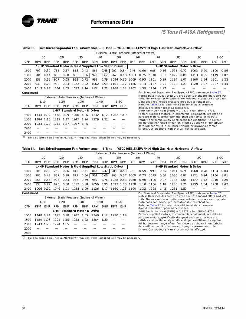
58 RT-PRC023-EN
Performance Data
(5 Tons R-410A Refrigerant)
Table 63. Belt Drive Evaporator Fan Performance — 5 Tons — YSC060E3,E4,EW*HH High Gas Heat Downflow Airflow
External Static Pressure (Inches of Water)
.10 .20 .30 .40 .50 .60 .70 .80 .90 1.00
CFM RPM BHP RPM BHP RPM BHP RPM BHP RPM RPM BHP RPM BHP RPM BHP RPM BHP RPM BHP BHP
1-HP Standard Motor & Field Supplied Low Static Drive(i)
(i) Field Su pplied Fan Sheave AK71x3/4" required. Field Supplied Belt may be necessary.
1-HP Standard Motor & Drive
1600 709 0.32 766 0.37 818 0.43 862 0.48 902 0.54 944 0.60 985 0.66 1025 0.72 1063 0.79 1100 0.86
1800 784 0.44 835 0.50 885 0.56 928 0.62 967 0.68 1003 0.75 1040 0.81 1077 0.88 1113 0.95 1149 1.02
2000 859 0.58 907 0.65 952 0.72 995 0.79 1034 0.86 1069 0.93 1101 0.99 1134 1.07 1168 1.14 1201 1.22
2200 936 0.76 980 0.84 1022 0.92 1062 0.99 1101 1.07 1136 1.14 1167 1.21 1198 1.29 1228 1.37 1257 1.44
2400 1013 0.97 1054 1.05 1093 1.14 1131 1.22 1168 1.31 1202 1.39 1234 1.47 — — — — — —
Continued For Standard Evaporator Fan Speed (RPM), reference Table 67.Notes: Data inc ludes pressure drop due to standard filters an d wetcoils. No accessories or options are included in pressure drop data.Data does not include pressure drop due to reheat coil.Refer to Table 72 to determine additional s tatic pressu redrop due to other options/accessories.1-HP Fan Motor Heat (MBH) = 2.7672 x Fan BHP+0.4705.Factory supplied motors , in commercial equipment, are def initepurpose motors, sp ec ifically des igned and tested to operate reliably and continuou sly at all cataloged condit ion s. Us in g th efu ll horsepow er range of our fan motors as shown in our tabulardata will not result in nuisance tripping or prem ature m otor failure. Our produc t’s warran ty will not be affected.
External Static Pressure (Inches of Water)
1.10 1.20 1.30 1.40 1.50
CFM RPM BHP RPM BHP RPM BHP RPM BHP RPM BHP
1-HP Standard Motor & Drive
1600 1134 0.92 1168 0.99 1200 1.06 1232 1.12 1262 1.19
1800 1184 1.10 1217 1.17 1247 1.24 1279 1.32 — —
2000 1233 1.29 1265 1.37 1297 1.46 — — — —
2200 — — — — — — — — — —
2400 — — — — — — — — — —
Table 64. Belt Drive Evaporator Fan Performance — 5 Tons — YSC060E3,E4,EW*H,H High Gas Heat Horizontal Airflow
External Static Pressure (Inches of Water)
.10 .20 .30 .40 .50 .60 .70 .80 .90 1.00
CFM RPM BHP RPM BHP RPM BHP RPM BHP RPM RPM BHP RPM BHP RPM BHP RPM BHP RPM BHP BHP
1-HP Standard Motor & Field Supplied Low Static Drive(i)
(i) Field Su pplied Fan Sheave AK71x3/4" required. Field Supplied Belt may be necessary.
1-HP Standard Motor & Drive
1600 706 0.30 762 0.36 813 0.41 862 0.47 908 0.53 951 0.59 993 0.65 1031 0.71 1068 0.78 1104 0.84
1800 780 0.42 832 0.48 879 0.54 924 0.60 968 0.67 1009 0.73 1049 0.80 1086 0.87 1121 0.94 1156 1.01
2000 855 0.56 903 0.63 947 0.69 989 0.76 1028 0.83 1068 0.90 1106 0.97 1143 1.05 1177 1.12 1210 1.20
2200 930 0.72 976 0.80 1017 0.88 1056 0.95 1093 1.03 1130 1.10 1166 1.18 1200 1.26 1235 1.34 1268 1.42
2400 1006 0.92 1049 1.01 1088 1.09 1126 1.17 1160 1.25 1194 1.33 1228 1.42 1261 1.50 — — — —
Continued For Standard Evaporator Fan Speed (RPM), reference Table 67.Notes: Data inc ludes pressure drop due to standard filters an d wetcoils. No accessories or options are included in pressure drop data.Data does not include pressure drop due to reheat coil.Refer to Table 72 to determine additional s tatic pressu redrop due to other options/accessories.1-HP Fan Motor Heat (MBH) = 2.7672 x Fan BHP+0.4705.Factory supplied motors , in commercial equipment, are def initepurpose motors, sp ec ifically des igned and tested to operate reliably and continuou sly at all cataloged condit ion s. Us in g th efu ll horsepow er range of our fan motors as shown in our tabulardata will not result in nuisance tripping or prem ature m otor failure. Our produc t’s warran ty will not be affected.
External Static Pressure (Inches of Water)
1.10 1.20 1.30 1.40 1.50
CFM RPM BHP RPM BHP RPM BHP RPM BHP RPM BHP
1-HP Standard Motor & Drive
1600 1140 0.91 1173 0.98 1207 1.05 1240 1.12 1270 1.19
1800 1189 1.08 1221 1.15 1253 1.22 1284 1.30 — —
2000 1243 1.28 1274 1.35 — — — — — —
2200 — — — — — — — — — —
2400 — — — — — — — — — —

RT-PRC023-EN 59
Performance Data
(5 Tons R-410A Refrigerant)
Table 65. Belt Drive Evaporator Fan Performance — 5 Tons — WSC060E3,E4,EW Downflow Airflow
External Static Pressure (Inches of Water)
.10 .20 .30 .40 .50 .60 .70 .80 .90 1.00
CFM RPM BHP RPM BHP RPM BHP RPM BHP RPM RPM BHP RPM BHP RPM BHP RPM BHP RPM BHP BHP
1-HP Standard Motor & Field Supplied Low Static Drive(i)
(i) Field Su pplied Fan Sheave AK71x3/4" required. Field Supplied Belt may be necessary.
1-HP Standard Motor & Drive
1600 — — — — 606 0.26 660 0.31 710 0.36 757 0.41 802 0.46 846 0.52 889 0.58 930 0.65
1800 — — 582 0.27 640 0.32 692 0.38 740 0.43 785 0.49 827 0.55 868 0.60 908 0.67 947 0.73
2000 564 0.28 622 0.34 675 0.40 725 0.46 772 0.52 815 0.58 856 0.64 895 0.71 933 0.77 969 0.84
2200 608 0.36 663 0.42 712 0.49 760 0.55 805 0.62 847 0.69 886 0.76 924 0.82 961 0.89 995 0.96
2400 653 0.45 705 0.52 752 0.59 796 0.66 839 0.74 880 0.81 919 0.88 955 0.96 990 1.03 1024 1.11
Continued For Standard Evaporator Fan Speed (RPM), reference Table 67.Notes: Data inc ludes pressure drop due to standard filters an d wetcoils. No accessories or options are included in pressure drop data.Data does not include pressure drop due to reheat coil.Refer to Table 72 to determine additional s tatic pressu redrop due to other options/accessories.1-HP Fan Motor Heat (MBH) = 2.7672 x Fan BHP+0.4705.Factory supplied motors , in commercial equipment, are def initepurpose motors, sp ec ifically des igned and tested to operate reliably and continuou sly at all cataloged condit ion s. Us in g th efu ll horsepow er range of our fan motors as shown in our tabulardata will not result in nuisance tripping or prem ature m otor failure. Our produc t’s warran ty will not be affected.
External Static Pressure (Inches of Water)
1.10 1.20 1.30 1.40 1.50
CFM RPM BHP RPM BHP RPM BHP RPM BHP RPM BHP
1-HP Standard Motor & Drive
1600 968 0.71 1005 0.78 1040 0.84 1076 0.91 1108 0.98
1800 986 0.80 1022 0.87 1058 0.94 1092 1.02 1124 1.09
2000 1005 0.91 1041 0.98 1075 1.05 1110 1.13 1142 1.21
2200 1030 1.03 1063 1.11 1095 1.18 1127 1.26 1160 1.34
2400 1057 1.18 1089 1.26 1120 1.34 1151 1.42 1180 1.49
1-HP Standard Motor & Field Supplied Low Static Drive(ii)
(ii ) Field Su pplied Fan Sheave AK41x3/4" required. Field Supplied Belt may be necessary.
Table 66. Belt Drive Evaporator Fan Performance — 5 Tons — WSC060E3,E4,EW Horizontal Airflow
External Static Pressure (Inches of Water)
.10 .20 .30 .40 .50 .60 .70 .80 .90 1.00
CFM RPM BHP RPM BHP RPM BHP RPM BHP RPM RPM BHP RPM BHP RPM BHP RPM BHP RPM BHP BHP
1-HP Standard Motor & Field Supplied Low Static Drive(i)
(i) Field Su pplied Fan Sheave AK71x3/4" required. Field Supplied Belt may be necessary.
1-HP Standard Motor & Drive
1600 — — 573 0.23 642 0.29 705 0.35 764 0.42 821 0.49 873 0.56 919 0.64 963 0.71 1004 0.79
1800 — — 611 0.29 674 0.36 733 0.43 790 0.49 843 0.57 894 0.65 943 0.73 988 0.81 1030 0.90
2000 593 0.31 651 0.37 710 0.44 766 0.52 819 0.59 869 0.66 917 0.74 965 0.83 1010 0.92 1053 1.01
2200 641 0.40 694 0.46 747 0.54 799 0.62 850 0.70 898 0.78 945 0.86 988 0.95 1032 1.04 1075 1.14
2400 690 0.50 738 0.57 787 0.65 836 0.74 884 0.82 929 0.91 974 1.00 1016 1.09 1057 1.18 1096 1.27
Continued For Standard Evaporator Fan Speed (RPM), reference Table 67.Notes: Data inc ludes pressure drop due to standard filters an d wetcoils. No accessories or options are included in pressure drop data.Data does not include pressure drop due to reheat coil.Refer to Table 72 to determine additional s tatic pressu redrop due to other options/accessories.1-HP Fan Motor Heat (MBH) = 2.7672 x Fan BHP+0.4705.Factory supplied motors , in commercial equipment, are def initepurpose motors, sp ec ifically des igned and tested to operate reliably and continuou sly at all cataloged condit ion s. Us in g th efu ll horsepow er range of our fan motors as shown in our tabulardata will not result in nuisance tripping or prem ature m otor failure. Our produc t’s warran ty will not be affected.
External Static Pressure (Inches of Water)
1.10 1.20 1.30 1.40 1.50
CFM RPM BHP RPM BHP RPM BHP RPM BHP RPM BHP
1-HP Standard Motor & Drive
1600 1042 0.86 1076 0.93 1109 1.01 1141 1.08 1171 1.16
1800 1069 0.98 1106 1.06 1140 1.15 1173 1.23 1205 1.31
2000 1094 1.10 1131 1.20 1168 1.29 1203 1.38 1235 1.48
2200 1116 1.24 1154 1.34 1191 1.44 — — — —
2400 1136 1.38 1175 1.48 — — — — — —
1-HP Standard Motor & Field Supplied Low Static Drive(ii)
(ii ) Field Su pplied Fan Sheave AK41x3/4" required. Field Supplied Belt may be necessary.

60 RT-PRC023-EN
Table 67. Standard Motor & Sheave/Fan Speed (Rpm)
Unit Model Fan 6 Turns 5 Turns 4 Turns 3 Turns 2 Turns 1 Turn
Tons Number Sheave Open Open Open Open Open Open Closed
R-22 Refrigerant
3 T/YHC033A N/A N/A 745 819 894 968 1043 1117
4 T/YHC043A N/A N/A 833 916 1000 1083 1167 1250
5 T/YHC063A N/A N/A 897 987 1077 1166 1256 1346
R-410A Refrigerant
3 T/YSC036E3 AK51x3/4" N/A 765 835 905 975 1045 1115
4 T/YSC048E3 AK49x3/4" N/A 804 876 948 1020 1091 1163
5 T/YSC060E3 AK44x3/4" N/A 885 966 1049 1131 1212 1295
3 WSC036E3 AK51x3/4" N/A 761 835 909 982 1057 1125
4 WSC048E3 AK49x3/4" N/A 801 874 946 1019 1091 1164
5 WSC060E3 AK49X3/4" N/A 798 868 939 1010 1081 1152
Fac tory set at 3 turns open.
Table 68. Standard Motor & Low Static Drive Accessory Sheave/Fan Speed (Rpm)
Unit Model Fan 6 Turns 5 Turns 4 Turns 3 Turns 2 Turns 1 Turn
Tons Number Sheave Open Open Open Open Open Open Closed
R-22 Refrigerant
3 T/YHC033A AK84x3/4" N/A 427 470 512 555 597 640
AK69x3/4" N/A 522 574 627 679 732 784
4 T/YHC043A AK79x3/4" N/A 455 500 546 591 637 682
AK61x3/4" N/A 593 652 712 771 831 890
5 T/YHC063A AK71x3/4" N/A 507 558 609 659 710 761
AK59x3/4" N/A 614 675 737 798 860 921
R-410A Refrigerant
3 T/YSC036E3 AK71x3/4" N/A 556 606 657 707 757 808
4 T/YSC048E3 AK69x3/4" N/A N/A 624 675 727 779 832
5 T/YSC060E3 AK61x3/4" N/A N/A 708 765 823 880 938
3 WSC036E3 AK71x3/4" N/A 549 600 650 701 751 802
4 WSC048E3 AK69x3/4" N/A 567 619 671 723 775 828
5 WSC060E3 AK69x3/4" N/A 566 617 668 719 770 821
Fac tory set at 3 turns open.
Table 69. Standard Motor & High Static Drive Accessory Sheave/Fan Speed (Rpm)
Unit Model 6 Turns 5 Turns 4 Turns 3 Turns 2 Turns 1 Turn
Tons Number Open Open Open Open Open Open Closed
R-410A Refrigerant
3 T/YSC036E3 AK41x3/4" N/A 967 1040 1113 1187 N/A
4 T/YSC048E3 AK41x3/4" N/A 957 1033 1110 1187 1263
5 T/YSC060E3 N/A N/A N/A N/A N/A N/A N/A
3 WSC036E3 AK41 x 3/4" N/A 966 1041 1115 1190 N/A
4 WSC048E3 AK41 x 3/4" N/A 958 1034 1110 1186 1261
5 WSC060E3 AK41 x 3/4" N/A 970 1034 1097 1161 1224
Fac tory set at 3 turns open.
Performance Data
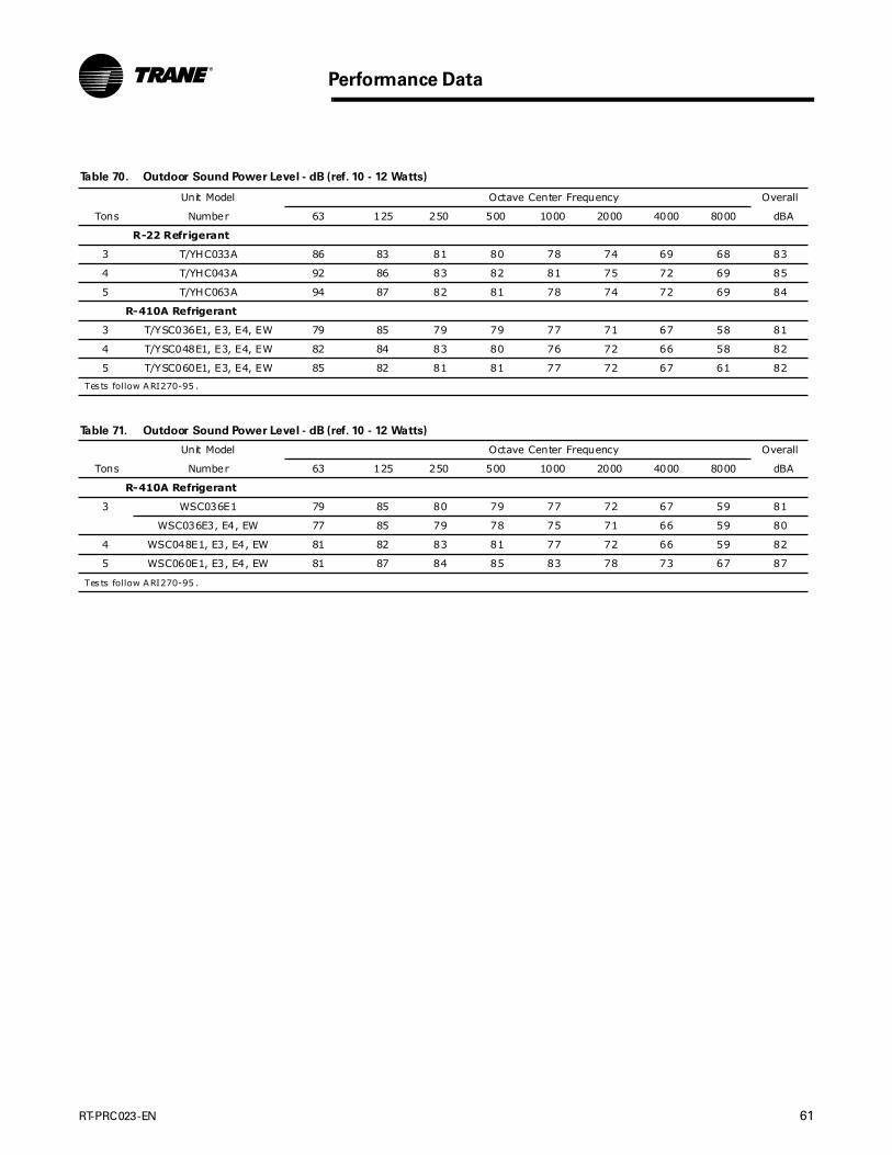
RT-PRC023-EN 61
Performance Data
Table 70. Outdoor Sound Power Level - dB (ref. 10 - 12 Watts)
Unit Model Octave Center Frequency Overall
Tons Number 63 125 250 500 1000 2000 4000 8000 dBA
R-22 Refrigerant
3 T/YHC033A 86 83 81 80 78 74 69 68 83
4 T/YHC043A 92 86 83 82 81 75 72 69 85
5 T/YHC063A 94 87 82 81 78 74 72 69 84
R-410A Refrigerant
3 T/YSC036E1, E3, E4, EW 79 85 79 79 77 71 67 58 81
4 T/YSC048E1, E3, E4, EW 82 84 83 80 76 72 66 58 82
5 T/YSC060E1, E3, E4, EW 85 82 81 81 77 72 67 61 82
Tests follow ARI270-95 .
Table 71. Outdoor Sound Power Level - dB (ref. 10 - 12 Watts)
Unit Model Octave Center Frequency Overall
Tons Number 63 125 250 500 1000 2000 4000 8000 dBA
R-410A Refrigerant
3 WSC036E1 79 85 80 79 77 72 67 59 81
WSC036E3, E4, EW 77 85 79 78 75 71 66 59 80
4 WSC048E1, E3, E4, EW 81 82 83 81 77 72 66 59 82
5 WSC060E1, E3, E4, EW 81 87 84 85 83 78 73 67 87
Tests follow ARI270-95 .
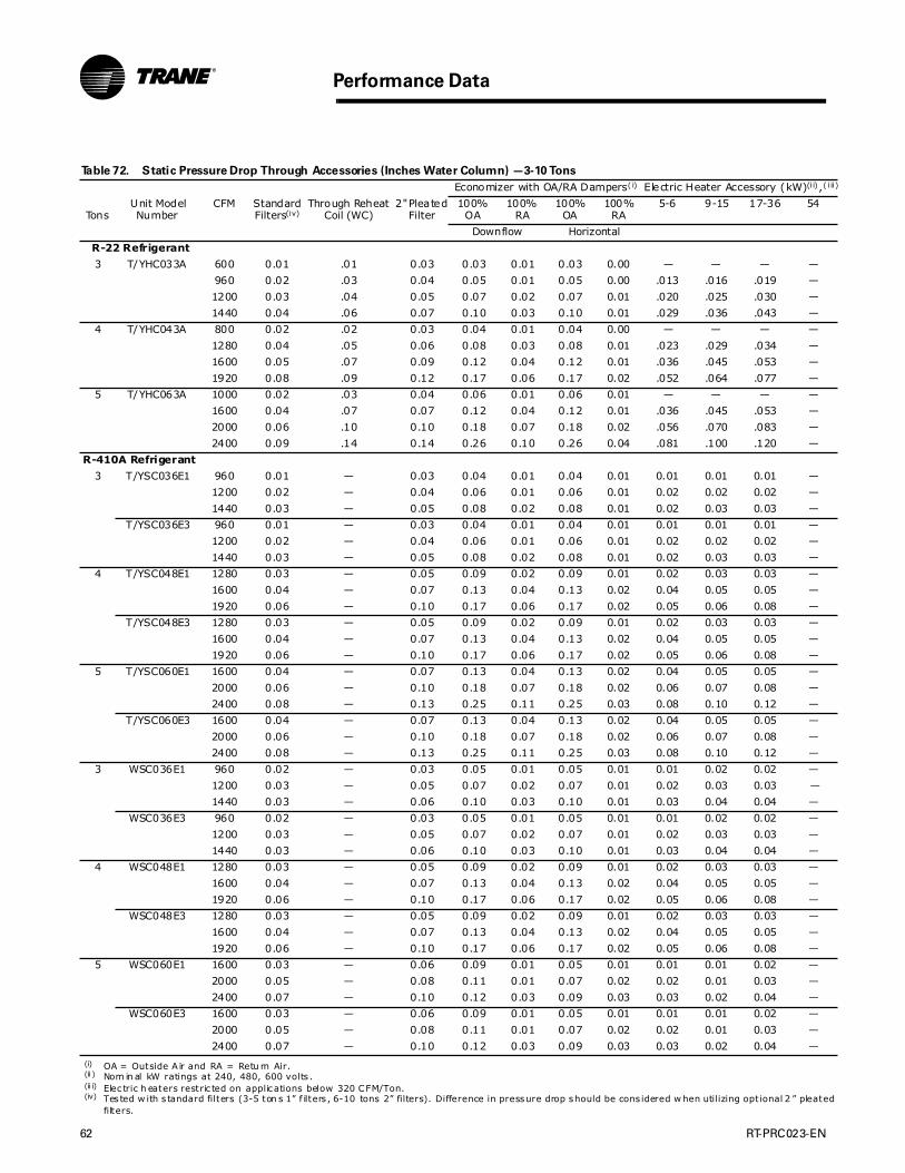
62 RT-PRC023-EN
Performance Data
Table 72. Static Pressure Drop Through Accessories (Inches Water Column) —3-10 Tons
Economizer with OA/RA Dampers( i)
(i) OA = Outside A ir and RA = Retu rn Air.
Electric Heater Accessory (kW)(i i) ,( i ii )
(ii ) Nom in al kW ratings at 240, 480, 600 volts .(ii i) Elec tric h eaters restric ted on applications below 320 CFM/Ton.
TonsUnit ModelNumber
CFM StandardFilters(iv)
(iv) Tes ted w ith s tandard filters (3-5 ton s 1” f ilters , 6-10 tons 2” filters). Difference in pressure drop should be cons idered w hen utilizing optional 2 ” pleated filters.
Through Reheat Coil (WC)
2" Pleated Filter
100% OA
100% RA
100% OA
100% RA
5-6 9-15 17-36 54
Downflow Horizontal
R-22 Refrigerant
3 T/YHC033A 600 0.01 .01 0.03 0.03 0.01 0.03 0.00 — — — —
960 0.02 .03 0.04 0.05 0.01 0.05 0.00 .013 .016 .019 —
1200 0.03 .04 0.05 0.07 0.02 0.07 0.01 .020 .025 .030 —
1440 0.04 .06 0.07 0.10 0.03 0.10 0.01 .029 .036 .043 —
4 T/YHC043A 800 0.02 .02 0.03 0.04 0.01 0.04 0.00 — — — —
1280 0.04 .05 0.06 0.08 0.03 0.08 0.01 .023 .029 .034 —
1600 0.05 .07 0.09 0.12 0.04 0.12 0.01 .036 .045 .053 —
1920 0.08 .09 0.12 0.17 0.06 0.17 0.02 .052 .064 .077 —
5 T/YHC063A 1000 0.02 .03 0.04 0.06 0.01 0.06 0.01 — — — —
1600 0.04 .07 0.07 0.12 0.04 0.12 0.01 .036 .045 .053 —
2000 0.06 .10 0.10 0.18 0.07 0.18 0.02 .056 .070 .083 —
2400 0.09 .14 0.14 0.26 0.10 0.26 0.04 .081 .100 .120 —
R-410A Refrigerant
3 T/YSC036E1 960 0.01 — 0.03 0.04 0.01 0.04 0.01 0.01 0.01 0.01 —
1200 0.02 — 0.04 0.06 0.01 0.06 0.01 0.02 0.02 0.02 —
1440 0.03 — 0.05 0.08 0.02 0.08 0.01 0.02 0.03 0.03 —
T/YSC036E3 960 0.01 — 0.03 0.04 0.01 0.04 0.01 0.01 0.01 0.01 —
1200 0.02 — 0.04 0.06 0.01 0.06 0.01 0.02 0.02 0.02 —
1440 0.03 — 0.05 0.08 0.02 0.08 0.01 0.02 0.03 0.03 —
4 T/YSC048E1 1280 0.03 — 0.05 0.09 0.02 0.09 0.01 0.02 0.03 0.03 —
1600 0.04 — 0.07 0.13 0.04 0.13 0.02 0.04 0.05 0.05 —
1920 0.06 — 0.10 0.17 0.06 0.17 0.02 0.05 0.06 0.08 —
T/YSC048E3 1280 0.03 — 0.05 0.09 0.02 0.09 0.01 0.02 0.03 0.03 —
1600 0.04 — 0.07 0.13 0.04 0.13 0.02 0.04 0.05 0.05 —
1920 0.06 — 0.10 0.17 0.06 0.17 0.02 0.05 0.06 0.08 —
5 T/YSC060E1 1600 0.04 — 0.07 0.13 0.04 0.13 0.02 0.04 0.05 0.05 —
2000 0.06 — 0.10 0.18 0.07 0.18 0.02 0.06 0.07 0.08 —
2400 0.08 — 0.13 0.25 0.11 0.25 0.03 0.08 0.10 0.12 —
T/YSC060E3 1600 0.04 — 0.07 0.13 0.04 0.13 0.02 0.04 0.05 0.05 —
2000 0.06 — 0.10 0.18 0.07 0.18 0.02 0.06 0.07 0.08 —
2400 0.08 — 0.13 0.25 0.11 0.25 0.03 0.08 0.10 0.12 —
3 WSC036E1 960 0.02 — 0.03 0.05 0.01 0.05 0.01 0.01 0.02 0.02 —
1200 0.03 — 0.05 0.07 0.02 0.07 0.01 0.02 0.03 0.03 —
1440 0.03 — 0.06 0.10 0.03 0.10 0.01 0.03 0.04 0.04 —
WSC036E3 960 0.02 — 0.03 0.05 0.01 0.05 0.01 0.01 0.02 0.02 —
1200 0.03 — 0.05 0.07 0.02 0.07 0.01 0.02 0.03 0.03 —
1440 0.03 — 0.06 0.10 0.03 0.10 0.01 0.03 0.04 0.04 —
4 WSC048E1 1280 0.03 — 0.05 0.09 0.02 0.09 0.01 0.02 0.03 0.03 —
1600 0.04 — 0.07 0.13 0.04 0.13 0.02 0.04 0.05 0.05 —
1920 0.06 — 0.10 0.17 0.06 0.17 0.02 0.05 0.06 0.08 —
WSC048E3 1280 0.03 — 0.05 0.09 0.02 0.09 0.01 0.02 0.03 0.03 —
1600 0.04 — 0.07 0.13 0.04 0.13 0.02 0.04 0.05 0.05 —
1920 0.06 — 0.10 0.17 0.06 0.17 0.02 0.05 0.06 0.08 —
5 WSC060E1 1600 0.03 — 0.06 0.09 0.01 0.05 0.01 0.01 0.01 0.02 —
2000 0.05 — 0.08 0.11 0.01 0.07 0.02 0.02 0.01 0.03 —
2400 0.07 — 0.10 0.12 0.03 0.09 0.03 0.03 0.02 0.04 —
WSC060E3 1600 0.03 — 0.06 0.09 0.01 0.05 0.01 0.01 0.01 0.02 —
2000 0.05 — 0.08 0.11 0.01 0.07 0.02 0.02 0.01 0.03 —
2400 0.07 — 0.10 0.12 0.03 0.09 0.03 0.03 0.02 0.04 —
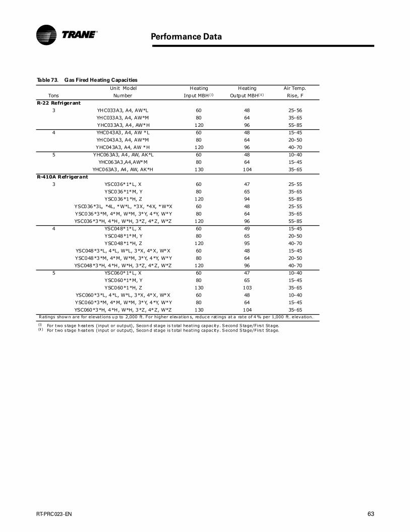
RT-PRC023-EN 63
Performance Data
Table 73. Gas Fired Heating Capacities
Unit Model Heating Heating Air Temp.
Tons Number Input MBH(i)
(i) For two s tage h eaters (input or output), Secon d stage is total heating capac ity. Second S tage/Firs t Stage.
Output MBH(ii)
(ii ) For two s tage h eaters (input or output), Secon d stage is total heating capac ity. Second S tage/Firs t Stage.
Rise, F
R-22 Refrigerant
3 YHC033A3, A4, AW*L 60 48 25-56
YHC033A3, A4, AW*M 80 64 35-65
YHC033A3, A4, AW*H 120 96 55-85
4 YHC043A3, A4, AW *L 60 48 15-45
YHC043A3, A4, AW*M 80 64 20-50
YHC043A3, A4, AW *H 120 96 40-70
5 YHC063A3, A4, AW, AK*L 60 48 10-40
YHC063A3,A4,AW*M 80 64 15-45
YHC063A3, A4, AW, AK*H 130 104 35-65
R-410A Refrigerant
3 YSC036*1*L, X 60 47 25-55
YSC036*1*M, Y 80 65 35-65
YSC036*1*H, Z 120 94 55-85
YSC036*3L, *4L, *W*L, *3X, *4X, *W*X 60 48 25-55
YSC036*3*M, 4*M, W*M, 3*Y, 4*Y, W*Y 80 64 35-65
YSC036*3*H, 4*H, W*H, 3*Z, 4*Z, W*Z 120 96 55-85
4 YSC048*1*L, X 60 49 15-45
YSC048*1*M, Y 80 65 20-50
YSC048*1*H, Z 120 95 40-70
YSC048*3*L, 4*L, W*L, 3*X, 4*X, W*X 60 48 15-45
YSC048*3*M, 4*M, W*M, 3*Y, 4*Y, W*Y 80 64 20-50
YSC048*3*H, 4*H, W*H, 3*Z, 4*Z, W*Z 120 96 40-70
5 YSC060*1*L, X 60 47 10-40
YSC060*1*M, Y 80 65 15-45
YSC060*1*H, Z 130 103 35-65
YSC060*3*L, 4*L, W*L, 3*X, 4*X, W*X 60 48 10-40
YSC060*3*M, 4*M, W*M, 3*Y, 4*Y, W*Y 80 64 15-45
YSC060*3*H, 4*H, W*H, 3*Z, 4*Z, W*Z 130 104 35-65Ratings show n are for elevations u p to 2,000 ft. For higher elevation s, reduce ratings at a rate of 4 % per 1,000 ft. elevation.
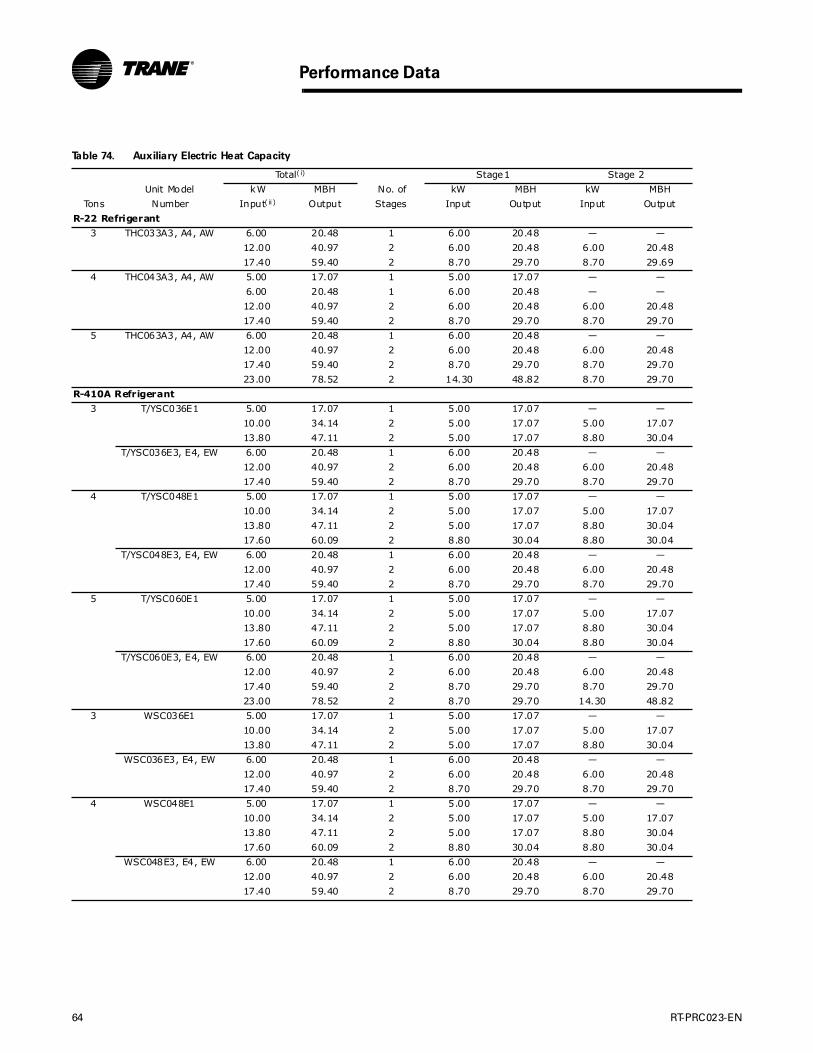
64 RT-PRC023-EN
Performance Data
Table 74. Auxiliary Electric Heat Capacity
Total( i) Stage1 Stage 2
Unit Model kW MBH No. of kW MBH kW MBH
Tons Number Input( ii ) Output Stages Input Output Input Output
R-22 Refrigerant
3 THC033A3, A4, AW 6.00 20.48 1 6.00 20.48 — —
12.00 40.97 2 6.00 20.48 6.00 20.48
17.40 59.40 2 8.70 29.70 8.70 29.69
4 THC043A3, A4, AW 5.00 17.07 1 5.00 17.07 — —
6.00 20.48 1 6.00 20.48 — —
12.00 40.97 2 6.00 20.48 6.00 20.48
17.40 59.40 2 8.70 29.70 8.70 29.70
5 THC063A3, A4, AW 6.00 20.48 1 6.00 20.48 — —
12.00 40.97 2 6.00 20.48 6.00 20.48
17.40 59.40 2 8.70 29.70 8.70 29.70
23.00 78.52 2 14.30 48.82 8.70 29.70
R-410A Refrigerant
3 T/YSC036E1 5.00 17.07 1 5.00 17.07 — —
10.00 34.14 2 5.00 17.07 5.00 17.07
13.80 47.11 2 5.00 17.07 8.80 30.04
T/YSC036E3, E4, EW 6.00 20.48 1 6.00 20.48 — —
12.00 40.97 2 6.00 20.48 6.00 20.48
17.40 59.40 2 8.70 29.70 8.70 29.70
4 T/YSC048E1 5.00 17.07 1 5.00 17.07 — —
10.00 34.14 2 5.00 17.07 5.00 17.07
13.80 47.11 2 5.00 17.07 8.80 30.04
17.60 60.09 2 8.80 30.04 8.80 30.04
T/YSC048E3, E4, EW 6.00 20.48 1 6.00 20.48 — —
12.00 40.97 2 6.00 20.48 6.00 20.48
17.40 59.40 2 8.70 29.70 8.70 29.70
5 T/YSC060E1 5.00 17.07 1 5.00 17.07 — —
10.00 34.14 2 5.00 17.07 5.00 17.07
13.80 47.11 2 5.00 17.07 8.80 30.04
17.60 60.09 2 8.80 30.04 8.80 30.04
T/YSC060E3, E4, EW 6.00 20.48 1 6.00 20.48 — —
12.00 40.97 2 6.00 20.48 6.00 20.48
17.40 59.40 2 8.70 29.70 8.70 29.70
23.00 78.52 2 8.70 29.70 14.30 48.82
3 WSC036E1 5.00 17.07 1 5.00 17.07 — —
10.00 34.14 2 5.00 17.07 5.00 17.07
13.80 47.11 2 5.00 17.07 8.80 30.04
WSC036E3, E4, EW 6.00 20.48 1 6.00 20.48 — —
12.00 40.97 2 6.00 20.48 6.00 20.48
17.40 59.40 2 8.70 29.70 8.70 29.70
4 WSC048E1 5.00 17.07 1 5.00 17.07 — —
10.00 34.14 2 5.00 17.07 5.00 17.07
13.80 47.11 2 5.00 17.07 8.80 30.04
17.60 60.09 2 8.80 30.04 8.80 30.04
WSC048E3, E4, EW 6.00 20.48 1 6.00 20.48 — —
12.00 40.97 2 6.00 20.48 6.00 20.48
17.40 59.40 2 8.70 29.70 8.70 29.70
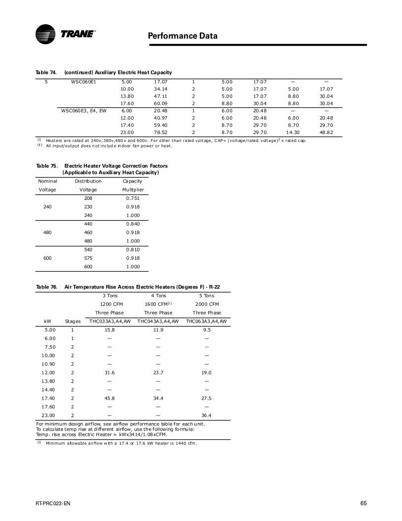
RT-PRC023-EN 65
Performance Data
5 WSC060E1 5.00 17.07 1 5.00 17.07 — —
10.00 34.14 2 5.00 17.07 5.00 17.07
13.80 47.11 2 5.00 17.07 8.80 30.04
17.60 60.09 2 8.80 30.04 8.80 30.04
WSC060E3, E4, EW 6.00 20.48 1 6.00 20.48 — —
12.00 40.97 2 6.00 20.48 6.00 20.48
17.40 59.40 2 8.70 29.70 8.70 29.70
23.00 78.52 2 8.70 29.70 14.30 48.82(i) Heaters are rated at 240v,380v,480 v and 600v. For other than rated voltage, CAP= (voltage/rated voltage)2 x rated cap.(ii ) All input/output does n ot inc lud e in door fan power or heat.
Table 75. Electric Heater Voltage Correction Factors
(Applicable to Auxiliary Heat Capacity)
Nominal Distribution Capacity
Voltage Voltage Multiplier
208 0.751
240 230 0.918
240 1.000
440 0.840
480 460 0.918
480 1.000
540 0.810
600 575 0.918
600 1.000
Table 76. Air Temperature Rise Across Electric Heaters (Degrees F) - R-22
3 Tons 4 Tons 5 Tons
1200 CFM 1600 CFM(i)
(i) Minimum allowable airflow w ith a 17.4 or 17.6 kW heater is 1440 cfm .
2000 CFM
Three Phase Three Phase Three Phase
kW Stages THC033A3,A4,AW THC043A3,A4,AW THC063A3,A4,AW
5.00 1 15.8 11.9 9.5
6.00 1 — — —
7.50 2 — — —
10.00 2 — — —
10.90 2 — — —
12.00 2 31.6 23.7 19.0
13.80 2 — — —
14.40 2 — — —
17.40 2 45.8 34.4 27.5
17.60 2 — — —
23.00 2 — — 36.4
For minimum design airflow, see airflow performance table for each unit.To calculate temp rise at different airflow, use the following formula: Temp. rise across Electric Heater = kWx3414/1.08xCFM.
Table 74. (continued) Auxil iary Electric Heat Capacity

66 RT-PRC023-EN
Performance Data
Table 77. Air Temperature Rise Across Electric Heaters (Degrees F) - R-410A
3 Tons(i)
(i) The minimum allow able airflow for a 3 ton with a 17 .4 kW heater is 1080 CFM.
4 Tons 5 Tons(i i)
(ii ) The minimum allow able airflow for a 5 ton unit with a 23.0 kW heater is 1 900 CFM.
1200 CFM 1600 CFM 2000 CFM
Single Phase Single Phase Single Phase Single Phase Single Phase Single Phase
kW Stages T/WSC036WE1 T/WSC036WE3,E4,EW T/WSC048WE1 T/WSC048WE3,E4,EW T/WSC060WE1 T/WSC060WE3,E4,EW
5.00 1 13.8 — 10.5 — 8.5 —
6.00 1 — 18.5 — 10.5 — 11.4
10.00 2 26.8 — 20.3 — 16.3 —
12.00 2 — 36.2 — 22.3 — 21.5
13.80 2 36.9 — 27.8 — 22.3 —
17.40 2 — 48.2 — 33.0 — 30.0
17.60 2 — — 35.5 — 28.3 —
23.0 2 — — — — — 38.8
For minimum design airflow, see airflow performance table for each unit. To calculate temp rise at different airflow, use the following formula: Temp. rise across Electric Heater = kWx3414/1.08xCFM.
Table 78. Hot Gas Reheat Temperature Rise(i),(ii), ( iii) - R-22
(i) Tem perature rise does n ot account for indoor fan heat.(ii ) 70 deg OD Amb ient Temperatu re.(ii i) For un its with the Dehum idif ication (Hot Gas Reheat) option.
Leaving Evaporator Dry Bulb [F]
Tons SCFM 35 40 45 50 55 60 65
3 600 20.3 20.0 19.6 19.2 18.8 18.4 18.0
720 19.4 19.1 18.7 18.3 17.9 17.6 17.2
840 18.5 18.2 17.9 17.5 17.1 16.7 16.3
960 17.6 17.3 17.0 16.6 16.2 15.8 15.5
1080 16.7 16.4 16.1 15.7 15.4 15.0 14.6
1200 15.8 15.5 15.2 14.9 14.5 14.1 13.8
1320 14.9 14.6 14.3 14.0 13.6 13.3 12.9
1440 14.0 13.8 13.5 13.1 12.8 12.4 12.0
4 800 22.0 21.8 21.5 21.2 20.9 20.6 20.3
960 21.0 20.7 20.5 20.2 19.9 19.6 19.3
1120 20.0 19.7 19.5 19.2 18.9 18.6 18.2
1280 19.0 18.7 18.4 18.1 17.9 17.5 17.2
1440 17.9 17.7 17.4 17.1 16.9 16.5 16.2
1600 16.9 16.6 16.4 16.1 15.8 15.5 15.2
1760 15.9 15.6 15.4 15.1 14.8 14.5 14.2
1920 14.8 14.6 14.4 14.1 13.8 13.5 13.2
5 1000 23.7 23.6 23.4 23.2 23.0 22.8 22.5
1200 22.6 22.4 22.2 22.0 21.8 21.6 21.3
1400 21.4 21.2 21.0 20.9 20.7 20.4 20.2
1600 20.3 20.1 19.9 19.7 19.5 19.3 19.0
1800 19.1 18.9 18.7 18.5 18.4 18.1 17.8
2000 17.9 17.8 17.6 17.4 17.2 16.9 16.6
2200 16.8 16.6 16.4 16.2 16.0 15.7 15.4
2400 15.6 15.4 15.2 15.1 14.9 14.6 14.3
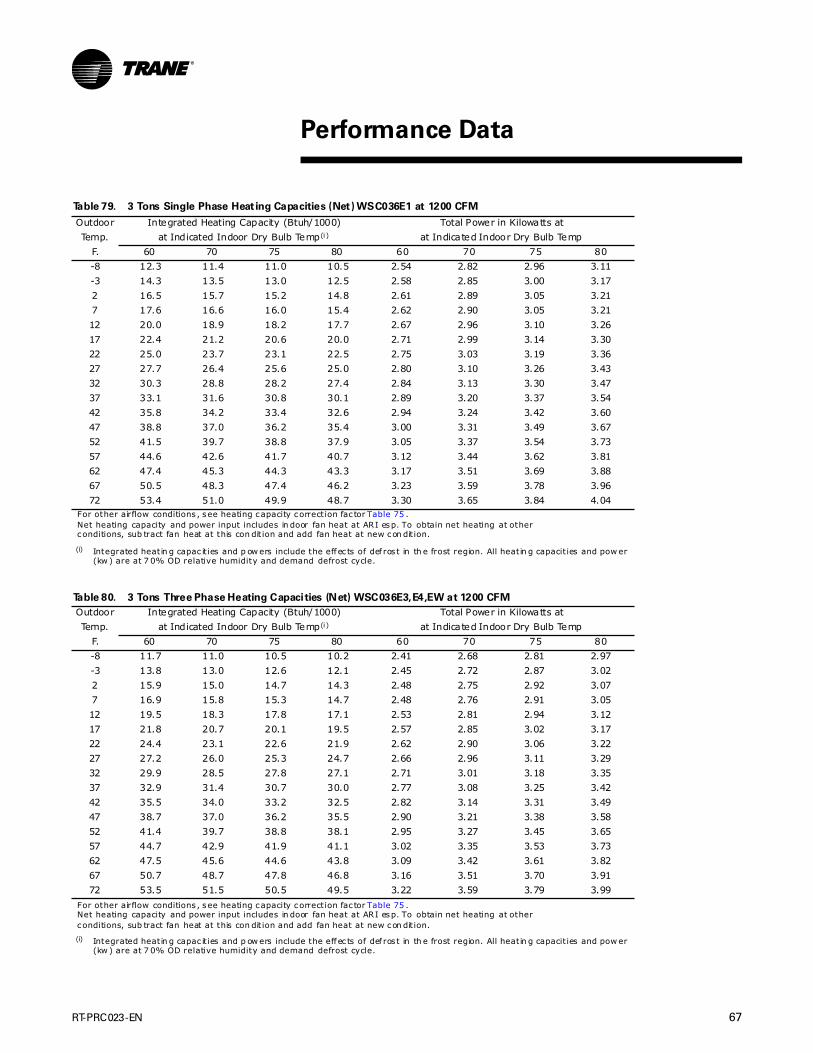
RT-PRC023-EN 67
Table 79. 3 Tons Single Phase Heating Capacities (Net) WSC036E1 at 1200 CFM
Outdoor Integrated Heating Capacity (Btuh/1000) Total Power in Kilowatts at
Temp. at Indicated Indoor Dry Bulb Temp(i)
(i) Integrated heatin g capac it ies and p ow ers include the effec ts of def ros t in th e frost region. All heatin g capacit ies and pow er (kw ) are at 7 0% OD relative humidity and demand defrost cycle.
at Indicated Indoor Dry Bulb Temp
F. 60 70 75 80 60 70 75 80
-8 12.3 11.4 11.0 10.5 2.54 2.82 2.96 3.11
-3 14.3 13.5 13.0 12.5 2.58 2.85 3.00 3.17
2 16.5 15.7 15.2 14.8 2.61 2.89 3.05 3.21
7 17.6 16.6 16.0 15.4 2.62 2.90 3.05 3.21
12 20.0 18.9 18.2 17.7 2.67 2.96 3.10 3.26
17 22.4 21.2 20.6 20.0 2.71 2.99 3.14 3.30
22 25.0 23.7 23.1 22.5 2.75 3.03 3.19 3.36
27 27.7 26.4 25.6 25.0 2.80 3.10 3.26 3.43
32 30.3 28.8 28.2 27.4 2.84 3.13 3.30 3.47
37 33.1 31.6 30.8 30.1 2.89 3.20 3.37 3.54
42 35.8 34.2 33.4 32.6 2.94 3.24 3.42 3.60
47 38.8 37.0 36.2 35.4 3.00 3.31 3.49 3.67
52 41.5 39.7 38.8 37.9 3.05 3.37 3.54 3.73
57 44.6 42.6 41.7 40.7 3.12 3.44 3.62 3.81
62 47.4 45.3 44.3 43.3 3.17 3.51 3.69 3.88
67 50.5 48.3 47.4 46.2 3.23 3.59 3.78 3.96
72 53.4 51.0 49.9 48.7 3.30 3.65 3.84 4.04For other airflow conditions , see heating capacity correction fac tor Table 75 .Net heating capacity and power input includes in door fan heat at ARI esp. To obtain net heating at other conditions, sub tract fan heat at this con dit ion and add fan heat at new con dit ion.
Table 80. 3 Tons Three Phase Heating Capacities (Net) WSC036E3,E4,EW at 1200 CFM
Outdoor Integrated Heating Capacity (Btuh/1000) Total Power in Kilowatts at
Temp. at Indicated Indoor Dry Bulb Temp(i)
(i) Integrated heatin g capac it ies and p ow ers include the effec ts of def ros t in th e frost region. All heatin g capacit ies and pow er (kw ) are at 7 0% OD relative humidity and demand defrost cycle.
at Indicated Indoor Dry Bulb Temp
F. 60 70 75 80 60 70 75 80
-8 11.7 11.0 10.5 10.2 2.41 2.68 2.81 2.97
-3 13.8 13.0 12.6 12.1 2.45 2.72 2.87 3.02
2 15.9 15.0 14.7 14.3 2.48 2.75 2.92 3.07
7 16.9 15.8 15.3 14.7 2.48 2.76 2.91 3.05
12 19.5 18.3 17.8 17.1 2.53 2.81 2.94 3.12
17 21.8 20.7 20.1 19.5 2.57 2.85 3.02 3.17
22 24.4 23.1 22.6 21.9 2.62 2.90 3.06 3.22
27 27.2 26.0 25.3 24.7 2.66 2.96 3.11 3.29
32 29.9 28.5 27.8 27.1 2.71 3.01 3.18 3.35
37 32.9 31.4 30.7 30.0 2.77 3.08 3.25 3.42
42 35.5 34.0 33.2 32.5 2.82 3.14 3.31 3.49
47 38.7 37.0 36.2 35.5 2.90 3.21 3.38 3.58
52 41.4 39.7 38.8 38.1 2.95 3.27 3.45 3.65
57 44.7 42.9 41.9 41.1 3.02 3.35 3.53 3.73
62 47.5 45.6 44.6 43.8 3.09 3.42 3.61 3.82
67 50.7 48.7 47.8 46.8 3.16 3.51 3.70 3.91
72 53.5 51.5 50.5 49.5 3.22 3.59 3.79 3.99
For other airflow conditions , see heating capacity correction fac tor Table 75 .Net heating capacity and power input includes in door fan heat at ARI esp. To obtain net heating at other conditions, sub tract fan heat at this con dit ion and add fan heat at new con dit ion.
Performance Data

68 RT-PRC023-EN
Performance Data
(4 Tons)
Table 81. 4 Tons Single Phase Heating Capacities (Net) WSC048E1 at 1200 CFM
Outdoor Integrated Heating Capacity (Btuh/1000) Total Power in Kilowatts at
Temp. at Indicated Indoor Dry Bulb Temp(i)
(i) Integrated heatin g capac it ies and p ow ers include the effec ts of def ros t in th e frost region. All heatin g capacit ies and pow er (kw ) are at 7 0% OD relative humidity and demand defrost cycle.
at Indicated Indoor Dry Bulb Temp
F. 60 70 75 80 60 70 75 80
-8 15.2 14.0 13.4 12.8 3.23 3.60 3.81 4.02
-3 17.6 16.5 15.8 15.2 3.24 3.61 3.81 4.03
2 20.3 19.0 18.5 17.8 3.28 3.62 3.83 4.07
7 20.8 19.2 18.3 17.6 3.24 3.59 3.77 3.97
12 23.9 22.2 21.4 20.6 3.27 3.61 3.80 4.01
17 26.6 25.0 24.2 23.4 3.28 3.63 3.82 4.03
22 29.8 28.2 27.3 26.4 3.33 3.68 3.88 4.08
27 33.2 31.5 30.6 29.8 3.37 3.72 3.91 4.13
32 36.2 34.5 33.5 32.6 3.41 3.77 3.95 4.17
37 39.8 37.9 36.9 36.0 3.46 3.81 4.01 4.22
42 42.9 40.9 39.9 38.9 3.50 3.86 4.06 4.27
47 46.6 44.4 43.3 42.3 3.56 3.91 4.11 4.34
52 49.9 47.6 46.4 45.5 3.61 3.97 4.17 4.39
57 53.8 51.2 50.2 49.1 3.67 4.02 4.24 4.46
62 57.3 54.6 53.4 52.2 3.72 4.09 4.30 4.52
67 61.4 58.5 57.1 55.8 3.79 4.16 4.37 4.59
72 64.9 61.9 60.4 59.0 3.85 4.22 4.44 4.67For other airflow conditions , see heating capacity correction fac tor Table 75 .Net heating capacity and power input includes in door fan heat at ARI esp. To obtain net heating at other conditions, sub tract fan heat at this con dit ion and add fan heat at new con dit ion.
Table 82. 4 Tons Three Phase Heating Capacities (Net) WSC048E3,E4,EW at 1200 CFM
Outdoor Integrated Heating Capacity (Btuh/1000) Total Power in Kilowatts at
Temp. at Indicated Indoor Dry Bulb Temp(i)
(i) Integrated heatin g capac it ies and p ow ers include the effec ts of def ros t in th e frost region. All heatin g capacit ies and pow er (kw ) are at 7 0% OD relative humidity and demand defrost cycle.
at Indicated Indoor Dry Bulb Temp
F. 60 70 75 80 60 70 75 80
-8 13.9 12.3 11.4 10.4 3.02 3.33 3.51 3.69
-3 16.7 15.0 14.1 13.2 3.06 3.38 3.55 3.74
2 19.5 17.8 17.1 16.1 3.11 3.44 3.61 3.81
7 20.7 19.0 17.9 16.9 3.11 3.44 3.61 3.80
12 23.8 22.0 21.1 20.0 3.16 3.49 3.67 3.85
17 26.6 24.9 23.9 22.9 3.20 3.53 3.71 3.90
22 29.9 28.1 27.1 26.1 3.24 3.59 3.77 3.96
27 33.3 31.4 30.4 29.3 3.29 3.65 3.82 4.02
32 36.2 34.3 33.3 32.3 3.33 3.69 3.88 4.07
37 39.8 37.8 36.8 35.8 3.39 3.74 3.94 4.15
42 42.9 40.8 39.8 38.7 3.44 3.79 3.99 4.20
47 46.6 44.4 43.3 42.1 3.50 3.86 4.05 4.26
52 50.0 47.6 46.5 45.3 3.55 3.92 4.12 4.33
57 53.9 51.3 50.3 49.0 3.62 3.98 4.19 4.41
62 57.5 54.7 53.4 52.2 3.69 4.05 4.25 4.48
67 61.5 58.7 57.4 56.0 3.75 4.13 4.34 4.56
72 65.0 62.3 60.8 59.3 3.82 4.21 4.42 4.64
For other airflow conditions , see heating capacity correction fac tor Table 75 .Net heating capacity and power input includes in door fan heat at ARI esp. To obtain net heating at other conditions, sub tract fan heat at this con dit ion and add fan heat at new con dit ion.
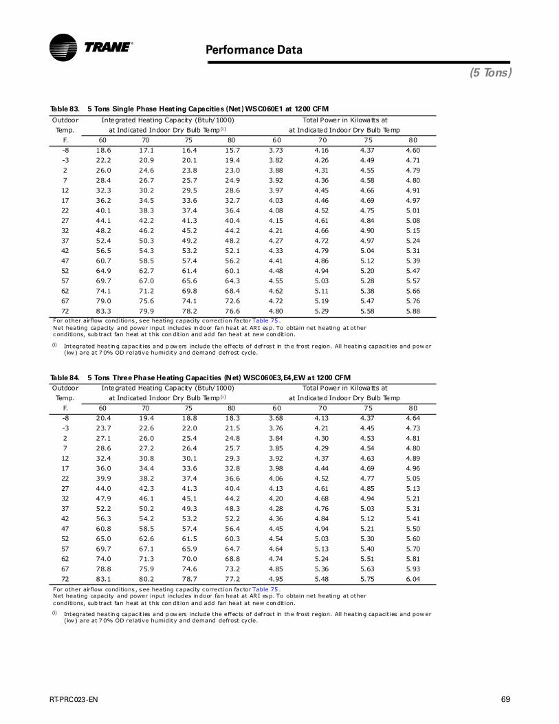
RT-PRC023-EN 69
Performance Data
(5 Tons)
Table 83. 5 Tons Single Phase Heating Capacities (Net) WSC060E1 at 1200 CFM
Outdoor Integrated Heating Capacity (Btuh/1000) Total Power in Kilowatts at
Temp. at Indicated Indoor Dry Bulb Temp(i)
(i) Integrated heatin g capac it ies and p ow ers include the effec ts of def ros t in th e frost region. All heatin g capacit ies and pow er (kw ) are at 7 0% OD relative humidity and demand defrost cycle.
at Indicated Indoor Dry Bulb Temp
F. 60 70 75 80 60 70 75 80
-8 18.6 17.1 16.4 15.7 3.73 4.16 4.37 4.60
-3 22.2 20.9 20.1 19.4 3.82 4.26 4.49 4.71
2 26.0 24.6 23.8 23.0 3.88 4.31 4.55 4.79
7 28.4 26.7 25.7 24.9 3.92 4.36 4.58 4.80
12 32.3 30.2 29.5 28.6 3.97 4.45 4.66 4.91
17 36.2 34.5 33.6 32.7 4.03 4.46 4.69 4.97
22 40.1 38.3 37.4 36.4 4.08 4.52 4.75 5.01
27 44.1 42.2 41.3 40.4 4.15 4.61 4.84 5.08
32 48.2 46.2 45.2 44.2 4.21 4.66 4.90 5.15
37 52.4 50.3 49.2 48.2 4.27 4.72 4.97 5.24
42 56.5 54.3 53.2 52.1 4.33 4.79 5.04 5.31
47 60.7 58.5 57.4 56.2 4.41 4.86 5.12 5.39
52 64.9 62.7 61.4 60.1 4.48 4.94 5.20 5.47
57 69.7 67.0 65.6 64.3 4.55 5.03 5.28 5.57
62 74.1 71.2 69.8 68.4 4.62 5.11 5.38 5.66
67 79.0 75.6 74.1 72.6 4.72 5.19 5.47 5.76
72 83.3 79.9 78.2 76.6 4.80 5.29 5.58 5.88For other airflow conditions , see heating capacity correction fac tor Table 75 .Net heating capacity and power input includes in door fan heat at ARI esp. To obtain net heating at other conditions, sub tract fan heat at this con dit ion and add fan heat at new con dit ion.
Table 84. 5 Tons Three Phase Heating Capacities (Net) WSC060E3,E4,EW at 1200 CFM
Outdoor Integrated Heating Capacity (Btuh/1000) Total Power in Kilowatts at
Temp. at Indicated Indoor Dry Bulb Temp(i)
(i) Integrated heatin g capac it ies and p ow ers include the effec ts of def ros t in th e frost region. All heatin g capacit ies and pow er (kw ) are at 7 0% OD relative humidity and demand defrost cycle.
at Indicated Indoor Dry Bulb Temp
F. 60 70 75 80 60 70 75 80
-8 20.4 19.4 18.8 18.3 3.68 4.13 4.37 4.64
-3 23.7 22.6 22.0 21.5 3.76 4.21 4.45 4.73
2 27.1 26.0 25.4 24.8 3.84 4.30 4.53 4.81
7 28.6 27.2 26.4 25.7 3.85 4.29 4.54 4.80
12 32.4 30.8 30.1 29.3 3.92 4.37 4.63 4.89
17 36.0 34.4 33.6 32.8 3.98 4.44 4.69 4.96
22 39.9 38.2 37.4 36.6 4.06 4.52 4.77 5.05
27 44.0 42.3 41.3 40.4 4.13 4.61 4.85 5.13
32 47.9 46.1 45.1 44.2 4.20 4.68 4.94 5.21
37 52.2 50.2 49.3 48.3 4.28 4.76 5.03 5.31
42 56.3 54.2 53.2 52.2 4.36 4.84 5.12 5.41
47 60.8 58.5 57.4 56.4 4.45 4.94 5.21 5.50
52 65.0 62.6 61.5 60.3 4.54 5.03 5.30 5.60
57 69.7 67.1 65.9 64.7 4.64 5.13 5.40 5.70
62 74.0 71.3 70.0 68.8 4.74 5.24 5.51 5.81
67 78.8 75.9 74.6 73.2 4.85 5.36 5.63 5.93
72 83.1 80.2 78.7 77.2 4.95 5.48 5.75 6.04
For other airflow conditions , see heating capacity correction fac tor Table 75 .Net heating capacity and power input includes in door fan heat at ARI esp. To obtain net heating at other conditions, sub tract fan heat at this con dit ion and add fan heat at new con dit ion.
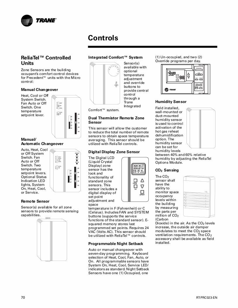
70 RT-PRC023-EN
ReliaTel™ Controlled Units
Zone Sensors are the building occupant’s comfort control devices for Precedent™ units with the Micro control:
Manual Changeover
Heat, Cool or Off System Switch. Fan Auto or Off Switch. One temperature setpoint lever.
Manual/Automatic Changeover
Auto, Heat, Cool or Off System Switch. Fan Auto or Off Switch. Two temperature setpoint levers. Optional Status Indication LED lights, System On, Heat, Cool, or Service.
Remote Sensor
Sensor(s) available for all zone sensors to provide remote sensing capabilities.
Integrated Comfort™ System
Sensor(s) available with optional temperature adjustment and override buttons to provide central control through a Trane Integrated
Comfort™ system.
Dual Thermistor Remote Zone Sensor
This sensor will allow the customer to reduce the total number of remote sensors to obtain space temperature averaging. This sensor should be utilized with ReliaTel controls.
Digital Display Zone Sensor
The Digital LCD (Liquid Crystal Display) zone sensor has the look and functionality of standard zone sensors. This sensor includes a digital display of set point adjustment and space temperature in F (Fahrenheit) or C (Celsius). Includes FAN and SYSTEM buttons (supports the service functions of the standard sensor). E-squared memory stores last programmed set points. Requires 24 VAC (Volts AC). This sensor should be utilized with ReliaTel™ controls.
Programmable Night Setback
Auto or manual changeover with seven-day programming. Keyboard selection of Heat, Cool, Fan, Auto, or On. All programmable sensors have System On, Heat, Cool, Service LED/indicators as standard. Night Setback Sensors have one (1) Occupied, one
(1) Un-occupied, and two (2) Override programs per day.
Humidity Sensor
Field installed, wall-mounted or duct-mounted humidity sensor is used to control activation of the hot gas reheat dehumidification option. The humidity sensor can be set for humidity levels between 40% and 60% relative humidity by adjusting the ReliaTel Options Module.
CO2 Sensing
The CO2 sensor shall have the ability to monitor space occupancy levels within the building by measuring the parts per million of CO2 (Carbon Dioxide) in the air. As the CO2 levels increase, the outside air damper modulates to meet the CO2 space ventilation requirements. The CO2 accessory shall be available as field installed.
MODE
MoMo
PMPM
OCCUPIEDOCCUPIED MODE
AUTO
FAN
AUTO
Controls
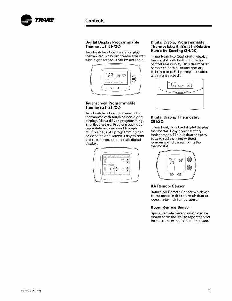
RT-PRC023-EN 71
Controls
Digital Display Programmable Thermostat (2H/2C)
Two Heat/Two Cool digital display thermostat. 7-day programmable stat with night setback shall be available.
Touchscreen Programmable Thermostat (2H/2C)
Two Heat/Two Cool programmable thermostat with touch screen digital display. Menu-driven programming. Effortless set-up. Program each day separately with no need to copy multiple days. All programming can be done on one screen. Easy to read and use. Large, clear backlit digital display.
System & Fan Override More
Tue
Heat Auto
Hold Until
DONE WAKE LEAVE RETURN SLEEPEDIT CANCEL
MON TUE WED THU FRI SAT SUN
PM
FANON
AUTOCIRC
SYSTEMEM HEAT
HEATOFF
COOLAUTO
RESET
HEAT
COOL
DEHUMIDIFIERCANCELPERIOD
Digital Display Programmable Thermostat with Built-In Relative Humidity Sensing (3H/2C)
Three Heat/Two Cool digital display thermostat with built-in humidity control and display. This thermostat combines both humidity and dry bulb into one. Fully programmable with night setback.
Digital Display Thermostat (3H/2C)
Three Heat, Two Cool digital display thermostat. Easy access battery replacement. Flip-out door for easy battery replacement without removing or disassembling the thermostat.
RA Remote Sensor
Return Air Remote Sensor which can be mounted in the return air duct to report return air temperature.
Room Remote Sensor
Space Remote Sensor which can be mounted on the wall to report/control from a remote location in the space.
Tue
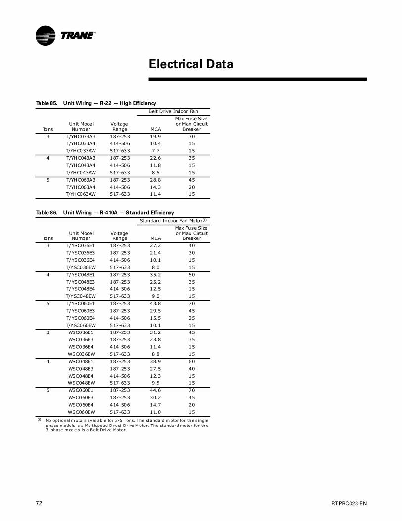
72 RT-PRC023-EN
Table 85. Unit Wiring — R-22 — High Efficiency
Belt Drive Indoor Fan
TonsUnit ModelNumber
VoltageRange MCA
Max Fuse Size or Max Circuit
Breaker
3 T/YHC033A3 187-253 19.9 30
T/YHC033A4 414-506 10.4 15
T/YHC033AW 517-633 7.7 15
4 T/YHC043A3 187-253 22.6 35
T/YHC043A4 414-506 11.8 15
T/YHC043AW 517-633 8.5 15
5 T/YHC063A3 187-253 28.8 45
T/YHC063A4 414-506 14.3 20
T/YHC063AW 517-633 11.4 15
Table 86. Unit Wiring — R-410A — Standard Efficiency
Standard Indoor Fan Motor(i)
(i) No optional m otors available for 3-5 Tons . The standard m otor for th e s ingle phase models is a Mult ispeed Direct Drive Motor. The standard motor for th e 3-phase m od els is a Belt Drive Motor.
TonsUnit ModelNumber
VoltageRange MCA
Max Fuse Size or Max Circuit
Breaker
3 T/YSC036E1 187-253 27.2 40
T/YSC036E3 187-253 21.4 30
T/YSC036E4 414-506 10.1 15
T/YSC036EW 517-633 8.0 15
4 T/YSC048E1 187-253 35.2 50
T/YSC048E3 187-253 25.2 35
T/YSC048E4 414-506 12.5 15
T/YSC048EW 517-633 9.0 15
5 T/YSC060E1 187-253 43.8 70
T/YSC060E3 187-253 29.5 45
T/YSC060E4 414-506 15.5 25
T/YSC060EW 517-633 10.1 15
3 WSC036E1 187-253 31.2 45
WSC036E3 187-253 23.8 35
WSC036E4 414-506 11.4 15
WSC036EW 517-633 8.8 15
4 WSC048E1 187-253 38.9 60
WSC048E3 187-253 27.5 40
WSC048E4 414-506 12.3 15
WSC048EW 517-633 9.5 15
5 WSC060E1 187-253 44.6 70
WSC060E3 187-253 30.2 45
WSC060E4 414-506 14.7 20
WSC060EW 517-633 11.0 15
Electrical Data
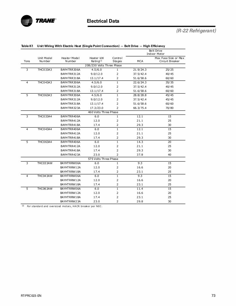
RT-PRC023-EN 73
Electrical Data
(R-22 Refrigerant)
Table 87. Unit Wiring With Electric Heat (Single Point Connection) — Belt Drive — High Efficiency
Belt DriveIndoor Motor
TonsUnit ModelNumber
Heater Model Number
Heater kW Rating( i)
(i) For s tandard and oversized motors , HACR breaker per NEC.
Control Stages MCA
Max Fuse Size or Max Circuit Breaker
208/230 Volts Three Phase
3 THC033A3 BAYHTRR306A 4.5/6.0 1 21.9/24.3 25/25
BAYHTRR312A 9.0/12.0 2 37.5/42.4 40/45
BAYHTRR318A 13.1/17.4 2 51.6/58.6 60/60
4 THC043A3 BAYHTRR306A 4.5/6.0 1 22.6/24.3 35/35
BAYHTRR312A 9.0/12.0 2 37.5/42.4 40/45
BAYHTRR318A 13.1/17.4 2 51.6/58.6 60/60
5 THC063A3 BAYHTRR306A 4.5/6.0 1 28.8/28.8 45/45
BAYHTRR312A 9.0/12.0 2 37.5/42.4 45/45
BAYHTRR318A 13.1/17.4 2 51.6/58.6 60/60
BAYHTRR323A 17.3/23.0 2 66.3/75.4 70/80
460 Volts Three Phase
3 THC033A4 BAYHTRR406A 6.0 1 12.1 15
BAYHTRR412A 12.0 2 21.1 25
BAYHTRR418A 17.4 2 29.3 30
4 THC043A4 BAYHTRR406A 6.0 1 12.1 15
BAYHTRR412A 12.0 2 21.1 25
BAYHTRR418A 17.4 2 29.3 30
5 THC063A4 BAYHTRR406A 6.0 1 14.3 20
BAYHTRR412A 12.0 2 21.1 25
BAYHTRR418A 17.4 2 29.3 30
BAYHTRR423A 23.0 2 37.8 40
575 Volts Three Phase
3 THC033AW BAYHTRRW06A 6.0 1 9.3 15
BAYHTRRW12A 12.0 2 16.6 20
BAYHTRRW18A 17.4 2 23.1 25
4 THC043AW BAYHTRRW06A 6.0 1 9.3 15
BAYHTRRW12A 12.0 2 16.6 20
BAYHTRRW18A 17.4 2 23.1 25
5 THC063AW BAYHTRRW06A 6.0 1 11.4 15
BAYHTRRW12A 12.0 2 16.6 20
BAYHTRRW18A 17.4 2 23.1 25
BAYHTRRW23A 23.0 2 29.8 30
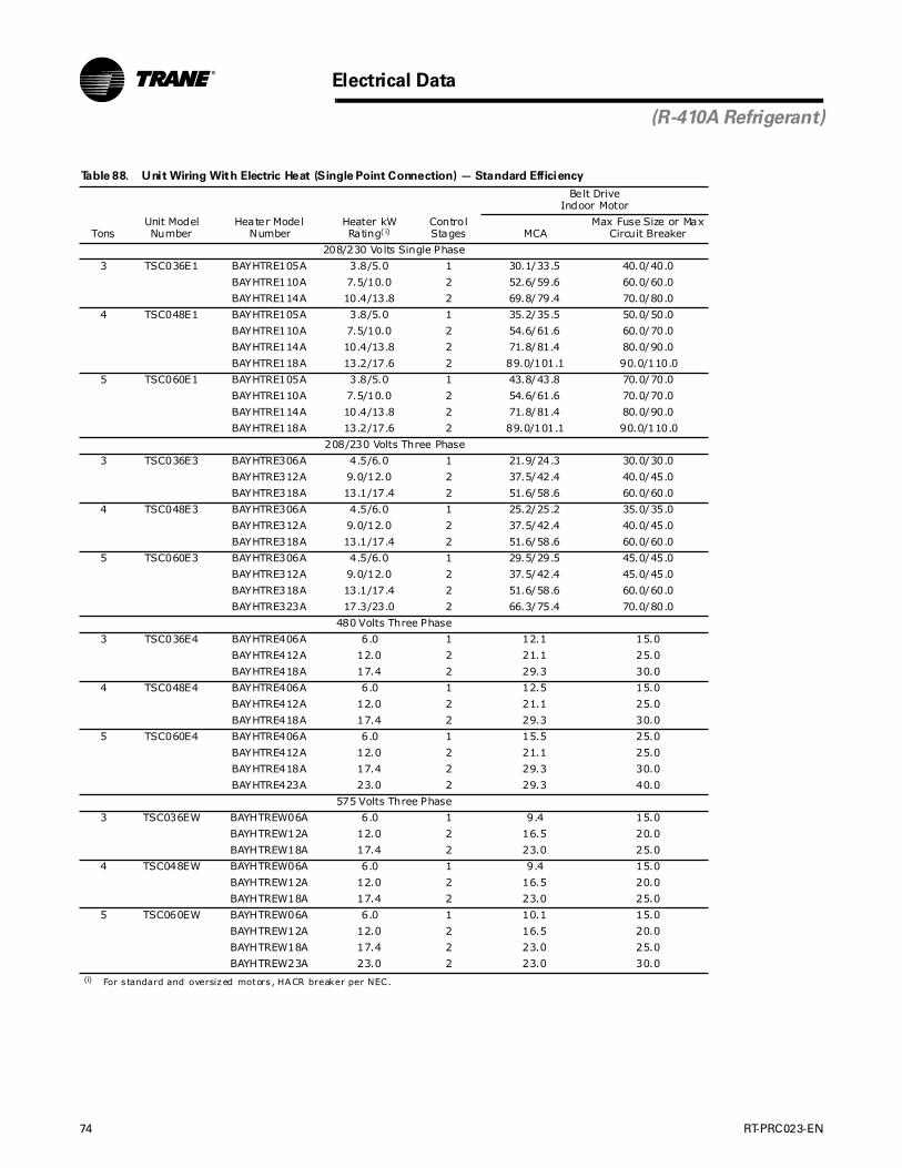
74 RT-PRC023-EN
Electrical Data
(R-410A Refrigerant)
Table 88. Unit Wiring With Electric Heat (Single Point Connection) — Standard Efficiency
Belt DriveIndoor Motor
TonsUnit ModelNumber
Heater Model Number
Heater kW Rating( i)
(i) For s tandard and oversized motors , HACR breaker per NEC.
Control Stages MCA
Max Fuse Size or Max Circuit Breaker
208/230 Volts Single Phase
3 TSC036E1 BAYHTRE105A 3.8/5.0 1 30.1/33.5 40.0/40.0
BAYHTRE110A 7.5/10.0 2 52.6/59.6 60.0/60.0
BAYHTRE114A 10.4/13.8 2 69.8/79.4 70.0/80.0
4 TSC048E1 BAYHTRE105A 3.8/5.0 1 35.2/35.5 50.0/50.0
BAYHTRE110A 7.5/10.0 2 54.6/61.6 60.0/70.0
BAYHTRE114A 10.4/13.8 2 71.8/81.4 80.0/90.0
BAYHTRE118A 13.2/17.6 2 89.0/101.1 90.0/110.0
5 TSC060E1 BAYHTRE105A 3.8/5.0 1 43.8/43.8 70.0/70.0
BAYHTRE110A 7.5/10.0 2 54.6/61.6 70.0/70.0
BAYHTRE114A 10.4/13.8 2 71.8/81.4 80.0/90.0
BAYHTRE118A 13.2/17.6 2 89.0/101.1 90.0/110.0
208/230 Volts Three Phase
3 TSC036E3 BAYHTRE306A 4.5/6.0 1 21.9/24.3 30.0/30.0
BAYHTRE312A 9.0/12.0 2 37.5/42.4 40.0/45.0
BAYHTRE318A 13.1/17.4 2 51.6/58.6 60.0/60.0
4 TSC048E3 BAYHTRE306A 4.5/6.0 1 25.2/25.2 35.0/35.0
BAYHTRE312A 9.0/12.0 2 37.5/42.4 40.0/45.0
BAYHTRE318A 13.1/17.4 2 51.6/58.6 60.0/60.0
5 TSC060E3 BAYHTRE306A 4.5/6.0 1 29.5/29.5 45.0/45.0
BAYHTRE312A 9.0/12.0 2 37.5/42.4 45.0/45.0
BAYHTRE318A 13.1/17.4 2 51.6/58.6 60.0/60.0
BAYHTRE323A 17.3/23.0 2 66.3/75.4 70.0/80.0
480 Volts Three Phase
3 TSC036E4 BAYHTRE406A 6.0 1 12.1 15.0
BAYHTRE412A 12.0 2 21.1 25.0
BAYHTRE418A 17.4 2 29.3 30.0
4 TSC048E4 BAYHTRE406A 6.0 1 12.5 15.0
BAYHTRE412A 12.0 2 21.1 25.0
BAYHTRE418A 17.4 2 29.3 30.0
5 TSC060E4 BAYHTRE406A 6.0 1 15.5 25.0
BAYHTRE412A 12.0 2 21.1 25.0
BAYHTRE418A 17.4 2 29.3 30.0
BAYHTRE423A 23.0 2 29.3 40.0
575 Volts Three Phase
3 TSC036EW BAYHTREW06A 6.0 1 9.4 15.0
BAYHTREW12A 12.0 2 16.5 20.0
BAYHTREW18A 17.4 2 23.0 25.0
4 TSC048EW BAYHTREW06A 6.0 1 9.4 15.0
BAYHTREW12A 12.0 2 16.5 20.0
BAYHTREW18A 17.4 2 23.0 25.0
5 TSC060EW BAYHTREW06A 6.0 1 10.1 15.0
BAYHTREW12A 12.0 2 16.5 20.0
BAYHTREW18A 17.4 2 23.0 25.0
BAYHTREW23A 23.0 2 23.0 30.0
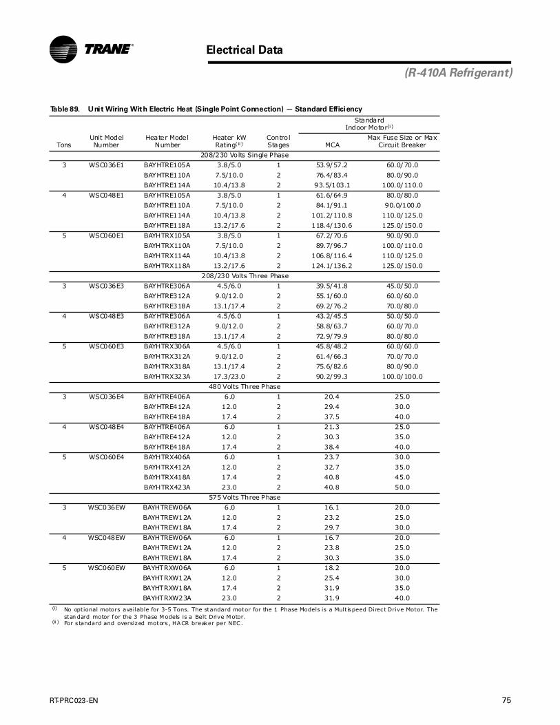
RT-PRC023-EN 75
Electrical Data
(R-410A Refrigerant)
Table 89. Unit Wiring With Electric Heat (Single Point Connection) — Standard Efficiency
StandardIndoor Motor(i)
(i) No optional motors available for 3-5 Tons. The standard motor for the 1 Phase Models is a Mult ispeed Direc t Drive Motor. The stan dard motor for the 3 Phase Models is a Belt Drive Motor.
TonsUnit ModelNumber
Heater Model Number
Heater kW Rating( ii )
(ii ) For s tandard and oversized motors , HACR breaker per NEC.
Control Stages MCA
Max Fuse Size or Max Circuit Breaker
208/230 Volts Single Phase
3 WSC036E1 BAYHTRE105A 3.8/5.0 1 53.9/57.2 60.0/70.0
BAYHTRE110A 7.5/10.0 2 76.4/83.4 80.0/90.0
BAYHTRE114A 10.4/13.8 2 93.5/103.1 100.0/110.0
4 WSC048E1 BAYHTRE105A 3.8/5.0 1 61.6/64.9 80.0/80.0
BAYHTRE110A 7.5/10.0 2 84.1/91.1 90.0/100.0
BAYHTRE114A 10.4/13.8 2 101.2/110.8 110.0/125.0
BAYHTRE118A 13.2/17.6 2 118.4/130.6 125.0/150.0
5 WSC060E1 BAYHTRX105A 3.8/5.0 1 67.2/70.6 90.0/90.0
BAYHTRX110A 7.5/10.0 2 89.7/96.7 100.0/110.0
BAYHTRX114A 10.4/13.8 2 106.8/116.4 110.0/125.0
BAYHTRX118A 13.2/17.6 2 124.1/136.2 125.0/150.0
208/230 Volts Three Phase
3 WSC036E3 BAYHTRE306A 4.5/6.0 1 39.5/41.8 45.0/50.0
BAYHTRE312A 9.0/12.0 2 55.1/60.0 60.0/60.0
BAYHTRE318A 13.1/17.4 2 69.2/76.2 70.0/80.0
4 WSC048E3 BAYHTRE306A 4.5/6.0 1 43.2/45.5 50.0/50.0
BAYHTRE312A 9.0/12.0 2 58.8/63.7 60.0/70.0
BAYHTRE318A 13.1/17.4 2 72.9/79.9 80.0/80.0
5 WSC060E3 BAYHTRX306A 4.5/6.0 1 45.8/48.2 60.0/60.0
BAYHTRX312A 9.0/12.0 2 61.4/66.3 70.0/70.0
BAYHTRX318A 13.1/17.4 2 75.6/82.6 80.0/90.0
BAYHTRX323A 17.3/23.0 2 90.2/99.3 100.0/100.0
480 Volts Three Phase
3 WSC036E4 BAYHTRE406A 6.0 1 20.4 25.0
BAYHTRE412A 12.0 2 29.4 30.0
BAYHTRE418A 17.4 2 37.5 40.0
4 WSC048E4 BAYHTRE406A 6.0 1 21.3 25.0
BAYHTRE412A 12.0 2 30.3 35.0
BAYHTRE418A 17.4 2 38.4 40.0
5 WSC060E4 BAYHTRX406A 6.0 1 23.7 30.0
BAYHTRX412A 12.0 2 32.7 35.0
BAYHTRX418A 17.4 2 40.8 45.0
BAYHTRX423A 23.0 2 40.8 50.0
575 Volts Three Phase
3 WSC036EW BAYHTREW06A 6.0 1 16.1 20.0
BAYHTREW12A 12.0 2 23.2 25.0
BAYHTREW18A 17.4 2 29.7 30.0
4 WSC048EW BAYHTREW06A 6.0 1 16.7 20.0
BAYHTREW12A 12.0 2 23.8 25.0
BAYHTREW18A 17.4 2 30.3 35.0
5 WSC060EW BAYHTRXW06A 6.0 1 18.2 20.0
BAYHTRXW12A 12.0 2 25.4 30.0
BAYHTRXW18A 17.4 2 31.9 35.0
BAYHTRXW23A 23.0 2 31.9 40.0
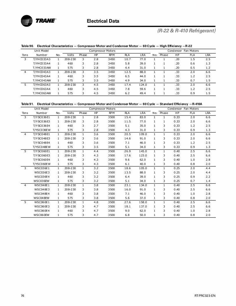
76 RT-PRC023-EN
Electrical Data
(R-22 & R-410 Refrigerant)
Table 90. Electrical Characteristics — Compressor Motor and Condenser Motor — 60 Cycle — High Efficiency —R-22
Unit Model Compressor Motors Condenser Fan Motors
Tons Number No. Volts Phase HP RPM RLA LRA No. Phase HP FLA LRA
3 T/YHC033A3 1 208-230 3 2.8 3450 10.7 77.0 1 1 .20 1.5 2.5
T/YHC033A4 1 460 3 2.8 3450 5.8 39.0 1 1 .20 0.6 1.3
T/YHC033AW 1 575 3 2.8 3450 4.4 31.0 1 1 .20 0.5 1.2
4 T/YHC043A3 1 208-230 3 3.5 3450 12.5 88.0 1 1 .33 2.0 6.6
T/YHC043A4 1 460 3 3.5 3450 6.5 44.0 1 1 .33 1.2 2.5
T/YHC043AW 1 575 3 3.5 3450 4.9 34.0 1 1 .33 0.7 1.5
5 T/YHC063A3 1 208-230 3 4.5 3450 17.4 124.0 1 1 .33 2.0 6.6
T/YHC063A4 1 460 3 4.5 3450 7.8 59.6 1 1 .33 1.2 2.5
T/YHC063AW 1 575 3 4.5 3450 6.2 49.4 1 1 .33 0.9 1.5
Table 91. Electrical Characteristics — Compressor Motor and Condenser Motor — 60 Cycle — Standard Efficiency —R-410A
Unit Model Compressor Motors Condenser Fan Motors
Tons Number No. Volts Phase HP RPM RLA LRA No. Phase HP FLA LRA
3 T/YSC036E1 1 208-230 1 2.8 3500 15.4 83.0 1 1 0.33 2.0 6.6
T/YSC036E3 1 208-230 3 2.8 3500 11.5 77.0 1 1 0.33 2.0 6.6
T/YSC036E4 1 460 3 2.7 3500 5.1 35.0 1 3 0.33 1.2 2.5
T/YSC036EW 1 575 3 2.8 3500 4.3 31.0 1 3 0.33 0.9 1.3
4 T/YSC048E1 1 208-230 1 3.6 3500 20.5 109.0 1 1 0.33 2.0 6.6
T/YSC048E3 1 208-230 3 3.6 3500 14.6 91.0 1 3 0.33 2.0 6.6
T/YSC048E4 1 460 3 3.6 3500 7.1 46.0 1 3 0.33 1.2 2.5
T/YSC048EW 1 575 3 3.5 3500 5.1 34.0 1 3 0.33 0.9 1.3
5 T/YSC060E1 1 208-230 1 4.4 3500 26.9 145.0 1 1 0.40 2.5 6.6
T/YSC060E3 1 208-230 3 4.3 3500 17.6 123.0 1 3 0.40 2.5 6.6
T/YSC060E4 1 460 3 4.3 3500 9.6 62.0 1 3 0.40 1.0 2.8
T/YSC060EW 1 575 3 4.3 3500 6.1 40.0 1 3 0.40 0.8 2.0
3 WSC036E1 1 208-230 1 3.2 3500 18.6 105.0 1 1 0.25 2.0 4.4
WSC036E3 1 208-230 3 3.2 3500 13.5 88.0 1 3 0.25 2.0 4.4
WSC036E4 1 460 3 3.2 3500 6.4 39.0 1 3 0.25 0.9 2.2
WSC036EW 1 575 3 3.2 3500 5.1 34.0 1 3 0.25 0.7 1.4
4 WSC048E1 1 208-230 1 3.8 3500 23.1 134.0 1 1 0.40 2.5 6.6
WSC048E3 1 208-230 3 3.8 3500 16.0 91.0 1 3 0.40 2.5 6.6
WSC048E4 1 460 3 3.8 3500 7.1 46.0 1 3 0.40 1.0 2.8
WSC048EW 1 575 3 3.8 3500 5.6 37.0 1 3 0.40 0.8 2.0
5 WSC060E1 1 208-230 1 4.8 3500 27.6 158.0 1 1 0.40 2.5 6.6
WSC060E3 1 208-230 3 4.7 3500 18.1 137.0 1 3 0.40 2.5 6.6
WSC060E4 1 460 3 4.7 3500 9.0 62.0 1 3 0.40 1.0 2.8
WSC060EW 1 575 3 4.7 3500 6.8 50.0 1 3 0.40 0.8 2.0

RT-PRC023-EN 77
Electrical Data
(R-22 & R-410A Refrigerant)
Table 92. Electrical Characteristics — Evaporator Fan Motor — 60 Cycle — Belt Drive — R-22
Unit Model Amps
Tons Number Volts Hz. Phase No. HP FLA RLA
3 T/YHC033A3 208-230 60 3 1 1.00 5.00 32.20
T/YHC033A4 460 60 3 1 1.00 2.50 16.10
T/YHC033AW 575 60 3 1 1.00 1.70 13.20
4 T/YHC043A3 208-230 60 3 1 1.00 5.00 32.20
T/YHC043A4 460 60 3 1 1.00 2.50 16.10
T/YHC043AW 575 60 3 1 1.00 1.70 13.20
5 T/YHC063A3 208-230 60 3 1 1.00 5.00 32.20
T/YHC063A4 460 60 3 1 1.00 2.50 16.10
T/YHC063AW 575 60 3 1 1.00 1.70 13.20
Table 93. Electrical Characteristics — Evaporator Fan Motor — 60 Cycle — Belt Drive — R-410A
Unit Model Amps
Tons Number Volts Hz. Phase No. HP FLA RLA
3 T/YSC036E1 208-230 60 1 1 0.75 6.0 —
T/YSC036E3 208-230 60 3 1 1.00 5.0 32.2
T/YSC036E4 460 60 3 1 1.00 2.5 16.1
T/YSC036EW 575 60 3 1 1.00 1.7 13.2
4 T/YSC048E1 208-230 60 1 1 1.00 7.6 —
T/YSC048E3 208-230 60 3 1 1.00 5.0 32.2
T/YSC048E4 460 60 3 1 1.00 2.5 16.1
T/YSC048EW 575 60 3 1 1.00 1.7 13.2
5 T/YSC060E1 208-230 60 1 1 1.00 7.6 —
T/YSC060E3 208-230 60 3 1 1.00 5.0 32.2
T/YSC060E4 460 60 3 1 1.00 2.5 16.1
T/YSC060EW 575 60 3 1 1.00 1.7 13.2
3 WSC036E1 208-230 60 1 1 0.75 6.0 —
WSC036E3 208-230 60 3 1 1.00 5.0 32.2
WSC036E4 460 60 3 1 1.00 2.5 16.1
WSC036EW 575 60 3 1 1.00 1.7 13.2
4 WSC048E1 208-230 60 1 1 1.00 7.6 —
WSC048E3 208-230 60 3 1 1.00 5.0 32.2
WSC048E4 460 60 3 1 1.00 2.5 16.1
WSC048EW 575 60 3 1 1.00 1.7 13.2
5 WSC060E1 208-230 60 1 1 1.00 7.6 —
WSC060E3 208-230 60 3 1 1.00 5.0 32.2
WSC060E4 460 60 3 1 1.00 2.5 16.1
WSC060EW 575 60 3 1 1.00 1.7 13.2
Table 94. Electrical Characteristics — Inducer Motor
Unit Model Number Stages HP RPM Volts Phase LRA
YSC036-060A 1 1/35 3000 208-230 1 0.6
YSC072A*L,M 1 1/35 3000/3000 208-230 1 0.6
YSC090,092,102A*L
YSC072A*H 2 1/15 3500 208-230 1 0.42
YSC090, 092,102A*M,H
YSC120A*L,M,H
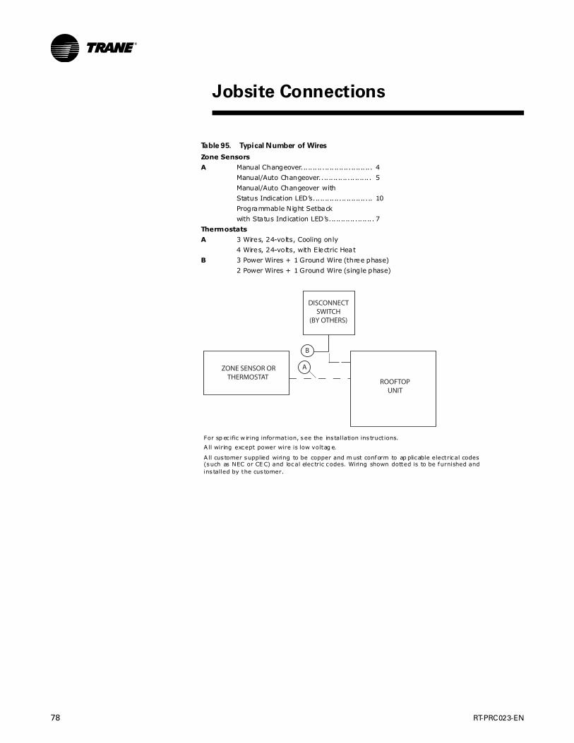
78 RT-PRC023-EN
Table 95. Typical Number of Wires
Zone Sensors
A Manual Changeover.............................. 4
Manual/Auto Changeover...................... 5
Manual/Auto Changeover with
Status Indication LED’s......................... 10
Programmable Night Setback
with Status Indication LED’s................... 7
Thermostats
A 3 Wires, 24-volts, Cooling only
4 Wires, 24-volts, with Electric Heat
B 3 Power Wires + 1 Ground Wire (three phase)
2 Power Wires + 1 Ground Wire (single phase)
For sp ec ific w iring information, see the ins tallation ins tructions.
A ll wiring except power wire is low voltag e.
A ll cus tomer supplied wiring to be copper and m ust conform to ap plicable electrical codes(such as NEC or CE C) and local elec tric codes. Wiring shown dotted is to be furnished andins talled by the cus tomer.
DISCONNECT SWITCH
(BY OTHERS)
ZONE SENSOR OR THERMOSTAT
ROOFTOPUNIT
A
B
Jobsite Connections
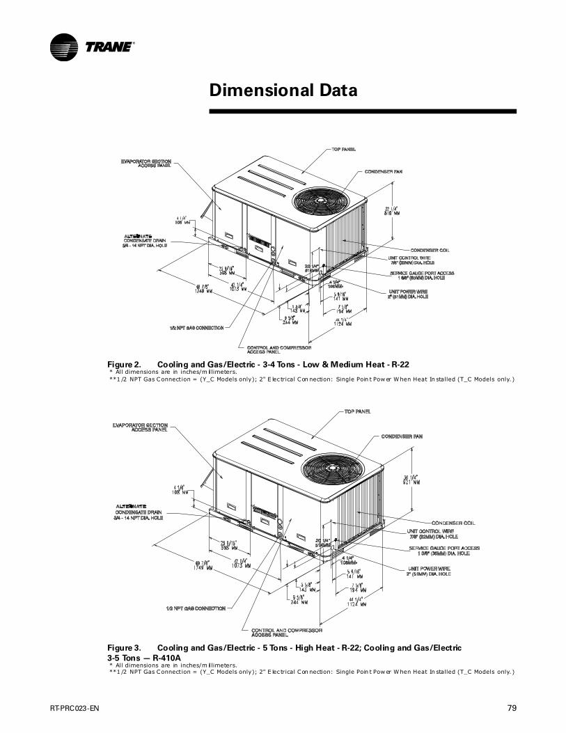
RT-PRC023-EN 79
Figure 2. Cooling and Gas/Electric - 3-4 Tons - Low & Medium Heat - R-22* All dimensions are in inches/m illimeters.**1 /2 NPT Gas Connection = (Y_C Models only); 2" E lec trical Con nection: Single Poin t Pow er W hen Heat In stalled (T_C Models only. )
Figure 3. Cooling and Gas/Electric - 5 Tons - High Heat - R-22; Cooling and Gas/Electric
3-5 Tons — R-410A* All dimensions are in inches/m illimeters.**1 /2 NPT Gas Connection = (Y_C Models only); 2" E lec trical Con nection: Single Poin t Pow er W hen Heat In stalled (T_C Models only. )
Dimensional Data

80 RT-PRC023-EN
Dimensional Data
(3-5 Tons)
Figure 4. Cooling and Gas/Electric Models 3-5 Tons
Downflow Airflow Supply/Return - Through the Base Utilities * All dimens ion s are in inches/millim eters.
Figure 5. Cooling and Gas/Electric Models 3-5 Tons - Horizontal Airflow
Supply/Return * All dimens ion s are in inches/millim eters.
Figure 6. Cooling and Gas/Electric Models 3-5 Tons - Unit Clearance
and Roof Opening* All dimens ion s are in inches/millim eters.
THROUGH THE BASE GAS(Y_C MODELS
ONLY)
THROUGH THE BASE
ELECTRICAL
SUPPLY
RETURN
TBU CONDENSATE
3 5/8”92 MM
14”356 MM
9 1/4”235 MM
15 1/2”394 MM
4”102 MM
24”610 MM
16”457 MM
27 9/16”701 MM
4 3/16”106 MM
4 9/16”116 MM
23 1/2”597 MM
2 13/16”71 MM 6 1/2”
165 MM3 11/16”94 MM
4 7/8”124 MM
5 1/16”128 MM
9 15/16”253 MM

RT-PRC023-EN 81
Dimensional Data
(3-5 Tons)
Figure 7. Cooling and Gas/Electric Models - 3-5 Tons - Roof Curb * A ll dim ensions are in inches/millim eters.
Figure 8. Cooling and Gas/Electric Models - 3-5 Tons - Downflow Duct
Connections - Field Fabricated* A ll dim ensions are in inches/millim eters.
7
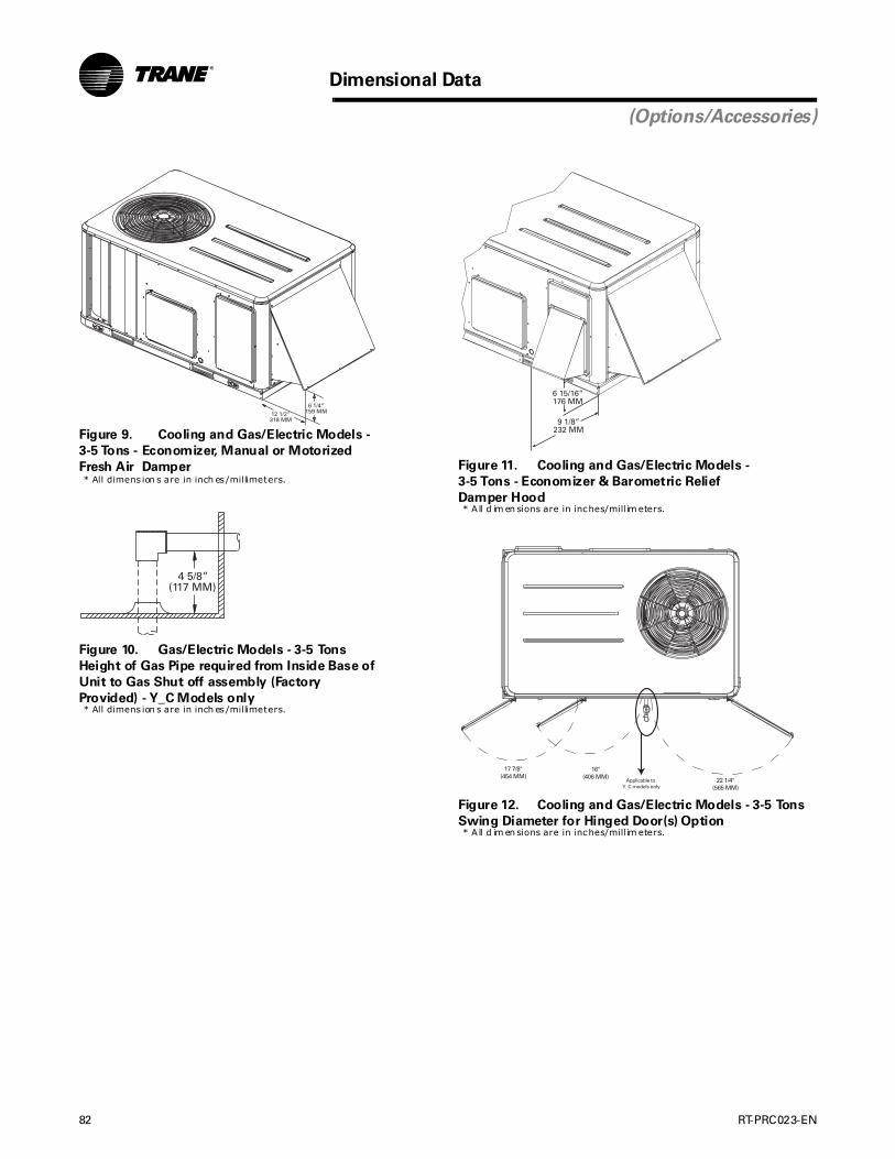
82 RT-PRC023-EN
Dimensional Data
(Options/Accessories)
Figure 9. Cooling and Gas/Electric Models -
3-5 Tons - Economizer, Manual or Motorized
Fresh Air Damper* All dimens ion s are in inch es/millimeters.
Figure 10. Gas/Electric Models - 3-5 Tons
Height of Gas Pipe required from Inside Base of
Unit to Gas Shut off assembly (Factory
Provided) - Y_C Models only* All dimens ion s are in inch es/millimeters.
Figure 11. Cooling and Gas/Electric Models -
3-5 Tons - Economizer & Barometric Relief
Damper Hood* A ll d im en sions are in inches/millim eters.
Figure 12. Cooling and Gas/Electric Models - 3-5 Tons
Swing Diameter for Hinged Door(s) Option* A ll d im en sions are in inches/millim eters.
17 7/8"(454 MM)
16"(406 MM) 22 1/4"
(565 MM)Applicable to
Y_C models only

RT-PRC023-EN 83
Dimensional Data
(3-4 Tons)
Figure 13. Heat Pumps - 3-4 Tons* All dimens ions are in inches/millimeters .
Figure 14. Heat Pump Models 3-4 Tons - Downflow Airflow Supply/Return
Through the Base Utilities* All dimens ions are in inches/millimeters .

84 RT-PRC023-EN
Dimensional Data
(3-4 Tons)
Figure 15. Heat Pump Models 3-4 Tons - Horizontal Airflow
Supply and Return* All dimens ion s are in inches/millim eters.
\
Figure 16. Heat Pump Models 3-4 Tons - Unit Clearance and Roof
Opening* All dimens ion s are in inches/millim eters.
Figure 17. Heat Pump Models - 3-4 Tons Roof Curb * All dimens ion s are in inches/millim eters.

RT-PRC023-EN 85
Dimensional Data
(3-4 Tons)
Figure 18. Heat Pump Models 3-4 Tons - Downflow
Duct Connections Field Fabricated* All dimens ion s are in inch es/millimeters.
Figure 19. Heat Pump Models - 3-4 Tons
Economizer, Manual or Motorized Fresh Air Damper* All dimens ion s are in inch es/millimeters.
7
Figure 20. Heat Pump Models - 3-4 Tons
Barometric Relief Damper Hood* All dimens ions are in inches/millimeters .
Figure 21. Heat Pump Models - 3-4 Tons Swing
Diameter for Hinged Door(s) Option* All dimens ions are in inches/millimeters .
17 7/8"(448 MM)
16"(406 MM)
22 1/4"(565 MM)

86 RT-PRC023-EN
Dimensional Data
(5 Tons)
Figure 22. Heat Pumps - 5 Tons* A ll dim ensions are in inches/millim eters.
Figure 23. Heat Pumps - 5 Tons - Downflow Airflow Supply/Return
Through the Base Utilities * A ll dim ensions are in inches/millim eters.

RT-PRC023-EN 87
Dimensional Data
Figure 24. Heat Pumps - 5 Tons - Horizontal Airflow Supply and Return* All dimens ion s are in inches/millim eters.
\
Figure 25. Heat Pumps - 5 Tons - Unit Clearance and Roof Opening* All dimens ion s are in inches/millim eters.
Supply
Return

88 RT-PRC023-EN
Dimensional Data
(5 Tons)
Figure 26. Heat Pumps - 5 Tons - Roof Curb * All dimensions are in inches/m illimeters.
Figure 27. Heat Pumps - 5 Tons - Downflow Duct Connections
Field Fabricated* All dimensions are in inches/m illimeters.
SUPP
LYRETU
RN
ALL FLANGES 1 1/4" (31 MM)
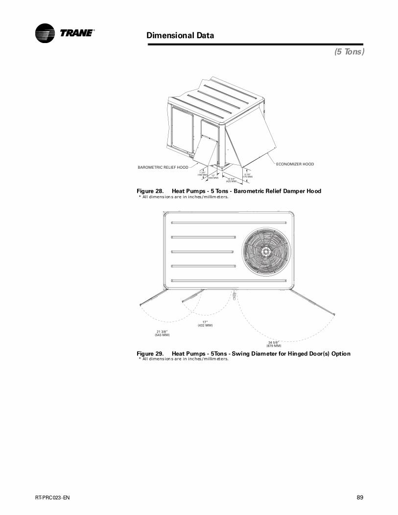
RT-PRC023-EN 89
Dimensional Data
(5 Tons)
Figure 28. Heat Pumps - 5 Tons - Barometric Relief Damper Hood* All dimens ion s are in inches/millim eters.
Figure 29. Heat Pumps - 5Tons - Swing Diameter for Hinged Door(s) Option* All dimens ion s are in inches/millim eters.
21 3/8”(543 MM)
17”(432 MM)
34 5/8”(879 MM)
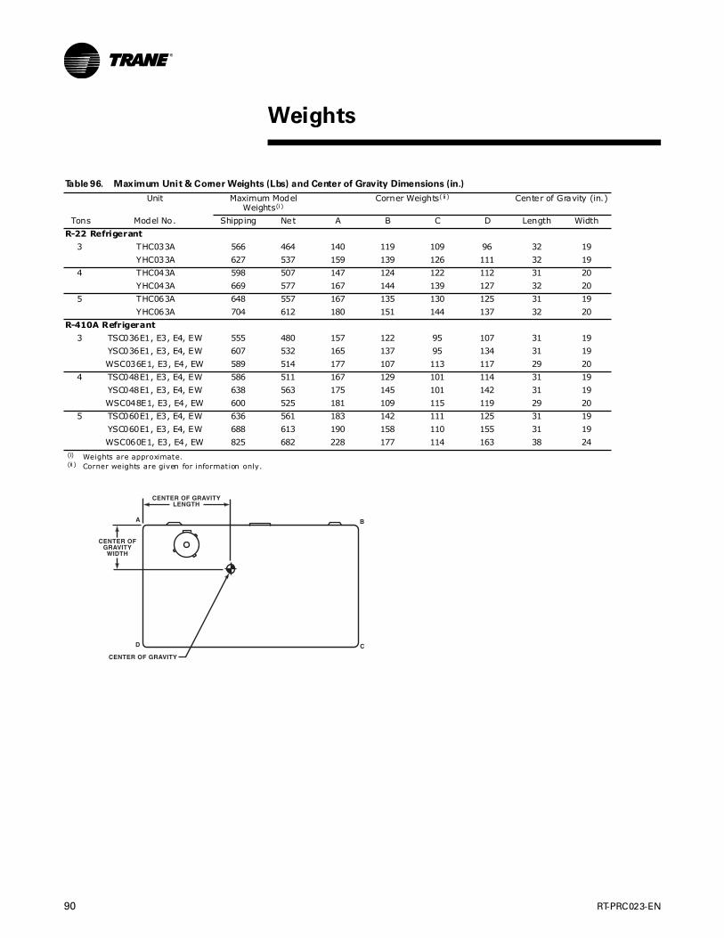
90 RT-PRC023-EN
Table 96. Maximum Unit & Corner Weights (Lbs) and Center of Gravity Dimensions (in.)
Unit Maximum Model Weights(i)
(i) Weights are approximate.
Corner Weights( ii )
(ii ) Corner weights are given for information only.
Center of Gravity (in.)
Tons Model No. Shipping Net A B C D Length Width
R-22 Refrigerant
3 THC033A 566 464 140 119 109 96 32 19
YHC033A 627 537 159 139 126 111 32 19
4 THC043A 598 507 147 124 122 112 31 20
YHC043A 669 577 167 144 139 127 32 20
5 THC063A 648 557 167 135 130 125 31 19
YHC063A 704 612 180 151 144 137 32 20
R-410A Refrigerant
3 TSC036E1, E3, E4, EW 555 480 157 122 95 107 31 19
YSC036E1, E3, E4, EW 607 532 165 137 95 134 31 19
WSC036E1, E3, E4, EW 589 514 177 107 113 117 29 20
4 TSC048E1, E3, E4, EW 586 511 167 129 101 114 31 19
YSC048E1, E3, E4, EW 638 563 175 145 101 142 31 19
WSC048E1, E3, E4, EW 600 525 181 109 115 119 29 20
5 TSC060E1, E3, E4, EW 636 561 183 142 111 125 31 19
YSC060E1, E3, E4, EW 688 613 190 158 110 155 31 19
WSC060E1, E3, E4, EW 825 682 228 177 114 163 38 24
Weights

RT-PRC023-EN 91
Weights
Table 97. Factory Installed Options (FIOPS)/Accessory Net Weights (Lbs)( i),(ii)
(i) Weights for options not listed are <5 lbs .(ii ) Net weight sh ou ld be added to unit weight when orderin g factory-ins talled accessories.
T/YSC & T/YHC WSC***E 3-5 Tons
Net Weight Net Weight
Accessory 3-5 Tons 3-4 Tons 5 Tons
Economizer 26 26 36
Barometric Relief 7 7 10
Powered Exhaust — — —
Motorized Outside Air Damper 20 20 30
Manual Outside Air Damper 16 16 26
Roof Curb 70 70 115
Oversized Motor — 5 8
Belt Drive Motor(i ii )
(ii i) Applicable to Gas/Electric units only.
38 38 —
Smoke Detector, Return 7 7 7
Smoke Detector, Supply 5 5 5
Coil Guards 12 12 20
Hinged Doors 10 10 12
Powered Convenience Outlet 38 38 38
Stainless Steel Heat Exchanger( iv )
(iv) Applicable to R-22 T/Y units only.
4 — —
Through the Base Electrical 8 8 13
Through the Base Gas 5 — —
Electric Heaters(v)
(v) Applicable to Cooling and Heat Pump u nits only.
15 15 `30
Unit Mounted Circuit Breaker 5 5 5
Unit Mounted Disconnect 5 5 5
Novar Control 8 5 5
Dehumidification (Hot Gas Reheat) Coil(vi)
(vi) Applicable to Gas/Electric units only.
15 — —

92 RT-PRC023-EN
General
The units shall be convertible airflow. The operating range shall be between 115°F and 0°F in cooling as standard from the factory for units with microprocessor controls. Operating range for units with electromechanical controls shall be between 115°F and 40°F. Cooling performance shall be rated in accordance with ARI testing procedures. All units shall be factory assembled, internally wired, fully charged with R-22 (T/YHC*) and R-410A (T/Y/WSC*), and 100 percent run tested to check cooling operation, fan and blower rotation, and control sequence before leaving the factory. Wiring internal to the unit shall be colored and numbered for simplified identification. Units shall be UL listed and labeled, classified in accordance to UL 1995/CAN/CSA No. 236-M90 for Central Cooling Air Conditioners. Canadian units shall be CSA Certified.
Casing
Unit casing shall be constructed of zinc coated, heavy gauge, galvanized steel. Exterior surfaces shall be cleaned, phosphatized, and finished with a weather-resistant baked enamel finish. Unit’s surface shall be tested 1000 hours in a salt spray test in compliance with ASTM B117. Cabinet construction shall allow for all maintenance on one side of the unit. Service panels shall have lifting handles and be removed and reinstalled by removing two fasteners while providing a water and air tight seal. All exposed vertical panels and top covers in the indoor air section shall be insulated with a cleanable foil-faced, fire-retardant permanent, odorless glass fiber material. The base of the unit shall be insulated with 1/8 inch, 1 pound density foil-faced, closed-cell material. All insulation edges shall be either captured or sealed. The unit’s base pan shall have no penetrations within the perimeter of the curb other than the raised 11/8 inch high downflow supply/return openings to provide an added water integrity precaution, if the condensate drain backs up. The base
of the unit shall have provisions for forklift and crane lifting, with forklift capabilities on three sides of the unit.
Compressors
All units shall have direct-drive, hermetic, scroll type compressors with centrifugal type oil pumps. Motor shall be suction gas-cooled and shall have a voltage utilization range of plus or minus 10 percent of unit nameplate voltage. Internal overloads shall be provided with the scroll compressors.
Controls
Unit shall be completely factory-wired with necessary controls and contactor pressure lugs or terminal block for power wiring. Unit shall provide an external location for mounting a fused disconnect device.
A choice of microprocessor or electromechanical controls shall be available.
Microprocessor controls provide for all 24 volt control functions. The resident control algorithms shall make all heating, cooling, and/or ventilating decisions in response to electronic signals from sensors measuring indoor and outdoor temperatures. The control algorithm maintains accurate temperature control, minimizes drift from set point, and provides better building comfort. A centralized microprocessor shall provide anti-short cycle timing and time delay between compressors to provide a higher level of machine protection.
24-volt electromechanical control circuit shall include control transformer and contactor pressure lugs for power wiring. Units shall have single point power entry as standard.
Evaporator and Condenser Coils
Internally finned, 5/16” copper tubes mechanically bonded to a configured aluminum plate fin shall be standard. Coils shall be leak tested at the factory to ensure the pressure integrity. The evaporator coil and condenser coil shall be leak tested to 200 psig and pressure tested to 450 psig. The condenser coil shall have a patent pending 1+1+1 hybrid coil designed with slight gaps for ease of cleaning. A removable, reversible, double-sloped condensate drain pan with provision for through the base condensate drain is standard.
Filters
One inch, throwaway filters shall be standard on all 3-5 ton units. The filter rack can be converted to two inch capability.
Gas Heating Section
The heating section shall have a progressive tubular heat exchanger design using stainless steel burners and corrosion resistant steel throughout. An induced draft combustion blower shall be used to pull the combustion products through the firing tubes. The heater shall use a direct spark ignition (DSI) system. On initial call for heat, the combustion blower shall purge the heat exchanger for 20 seconds before ignition After three unsuccessful ignition attempts, the entire heating system shall be locked out until manually reset at the thermostat/zone sensor. Units shall be suitable for use with natural gas or propane (field-installed kit) and also comply with the California requirement for low NOx emissions (Gas/Electric Only).
High Pressure Control
All units include High Pressure Cutout as standard.
Mechanical Specifications

RT-PRC023-EN 93
Mechanical Specifications
Indoor Fan
All 3-5 ton 3-phase units are belt driven, FC centrifugal fans with adjustable motor sheaves. 3-5 ton single phase R-410A units have multispeed, direct drive motors. All motors shall be thermally protected. All indoor fan motors meet the U.S. Energy Policy Act of 1992 (EPACT).
Outdoor Fans
The outdoor fan shall be direct-drive, statically and dynamically balanced, draw-through in the vertical discharge position. The fan motor shall be permanently lubricated and shall have built-in thermal overload protection.
Refrigerant Circuits
Each refrigerant circuit offer thermal expansion valve as standard. Service pressure ports, and refrigerant line filter driers are factory-installed as standard. An area shall be provided for replacement suction line driers.
Unit Top
The top cover shall be one piece construction or where seams exist, it shall be double-hemmed and gasket-sealed. The ribbed top adds extra strength and prevents water from pooling on unit top.
Factory Installed Options
Black Epoxy Pre-Coated Coils
The black epoxy coils have a thermoset vinyl coating that is bonded to the aluminum fin stock prior to the fin-stamping process. The pre-coated coils are an economical option for protection in mildly corrosive environments.
CompleteCoat™ Coils
The cathodic epoxy type electrodisposition coating is formulated for high edge build to plate fin and tube heat exchangers. The coating is selected to provide excellent resistance and durability to corrosive effects of alkalies, acids, alcohols, petroleum, seawater, salt air and corrosive environments.
Dehumidification Option (Available for R-22 units only)
The dehumidification (hot gas reheat) option shall provide increased dehumidification. The option shall consist of a hot-gas reheat coil located on the leaving air side of the evaporator coil prepiped and circuited.
The option shall be equipped with crankcase heater(s), low pressure switch(es), Frostat™, and a thermostatic expansion valve(s) (TXV) as standard.
Heat Exchanger
The compact cabinet features a tubular heat exchanger in low, medium and high heat capacities.
The heat exchanger is fabricated using stainless steel burners and corrosion-resistant aluminized steel tubes as standard on all models. It has an induced draft blower to pull the gas mixture through the burner tubes. The heater has a direct spark ignition system which doubles as a safety device to prove the flame.
Gas/Electric Precedent models exceed all California seasonal efficiency requirements. They also perform better than required to meet the California NOx emission requirements.
Hinged Access Doors
Sheet metal hinges are available on the Filter/Evaporator, Supply Fan/Heat, and the Compressor/Control Access Doors.
Novar Return Air Sensor
This option, when used in conjunction with Novar Controls, will contain a factory provided and wired zone temperature sensor located in the return air stream.
Novar Unit Controls
Optional Novar rooftop unit controls shall be installed and tested. The Novar electronic thermostat module will interface to the unit microprocessor and will control the unit to the desired stage of cooling or heating.
Phase Monitor
Phase monitor shall provide 100% protection for motors and compressors against problems caused by phase loss, phase imbalance, and phase reversal. Phase monitor is equipped with an LED that provides an ON or FAULT indicator.
Powered or Unpowered Convenience Outlet
This is a GFCI, 120v/15amp, 2 plug, convenience outlet, either powered or unpowered. When the convenience outlet is powered, a service receptacle disconnect will be available. The convenience outlet is powered from the line side of the disconnect or circuit breaker, and therefore will not be affected by the position of the disconnect or circuit breaker. This option can only be ordered when the Through the Base Electrical with either the Disconnect Switch or Circuit Breaker option is ordered.
Stainless Steel Heat Exchanger
The optional stainless steel heat exchanger is constructed of 304 stainless steel. It is resistant to corrosion and oxidation and easy to clean.
The high strength to weight ratio allows for high ventilation rates with gas units. It is an excellent option to compliment the dehumidification option as a high outside air ventilation unit.
With this option, a 10-year stainless steel heat exchanger warranty is standard.
Supply and/or Return Air Smoke Detector
With this option, if smoke is detected, all unit operation will be shut down. Reset will be manual at the unit. Return Air Smoke Detectors require minimum allowable airflow when used with certain models. See the Installation, Operation, and Maintenance (IOM) manual for the models affected and the minimum allowable airflow required. This option is available for microprocessor controlled units.
94 RT-PRC023-EN
Mechanical Specifications
Through the Base Electrical Access
An electrical service entrance shall be provided allowing electrical access for both control and main power connections inside the curb and through the base of the unit. Option will allow for field installation of liquid-tight conduit and an external field-installed disconnect switch.
Through the Base Electrical with Circuit Breaker
This option is a thermal magnetic, molded case, HACR Circuit Breaker with provisions for through the base electrical connections. The circuit breaker will be installed in a water tight enclosure in the unit with access through a swinging door. Wiring will be provided from the switch to the unit high voltage terminal block. The circuit breaker will provide overcurrent protection, be sized per NEC and UL guidelines, and be agency recognized by UL/CSA.
Through the Base Electrical with Disconnect Switch
This 3-pole, molded case, disconnect switch with provisions for through the base electrical connections are available. The disconnect switch will be installed in the unit in a water tight enclosure with access through a swinging door. Wiring will be provided from the switch to the unit high voltage terminal block. The switch will be UL/CSA agency recognized. Note: The disconnect switch will be sized per NEC and UL guidelines but will not be used in place of unit overcurrent protection.
Through the Base Gas Piping
The unit shall include a standard through the base gas provision. This option shall have all piping necessary including, black steel, manual gas shut-off valve, elbows, and union. The manual shut-off valve shall include a 1/8” NPT pressure tap. This assembly will require minor field labor to install (Gas/Electric Only).
Two-Inch Pleated Filters
Two inch pleated media filters shall be available on all models.
Factory or Field Installed Options
Clogged Filter/Fan Failure Switch
A dedicated differential pressure switch is available to achieve active fan failure indication and/or clogged filter indication. These indications will be registered with either a zone sensor with status indication lights or an Integrated Comfort™ System. This option is available for microprocessor controlled units.
Differential Pressure Switches
These sensors allow individual fan failure and dirty filter indication for microprocessor controlled units. The fan failure switch will disable all unit functions and “flash” the Service LED on the zone sensor. The dirty filter switch will light the Service LED on the zone sensor and will allow continued unit operation.
Discharge Air Sensing
This option provides true discharge air sensing in heating models. This sensor is a status indicator readable through Tracer™ or Tracker™. This option is available for microprocessor controlled units.
Economizer
This accessory shall be available with or without barometric relief. The assembly includes fully modulating 0-100 percent motor and dampers, minimum position setting, preset linkage, wiring harness with plug, spring return actuator and fixed dry bulb control. The barometric relief shall provide a pressure operated damper that shall be gravity closing and shall prohibit entrance of outside air during the equipment “off” cycle. Optional solid state or differential enthalpy control shall be available for either factory or field installation. The economizer arrives in the shipping position and shall be moved to the operating position by the installing contractor.
Electric Heaters
Electric heat modules shall be available for installation within basic unit. Electric heater elements shall be constructed of heavy-duty nickel chromium elements internally delta connected for 240 volt, wye
connected for 480 and 600 volt. Staging shall be achieved through ReliaTel™. Each heater package shall have automatically reset high limit control operating through heating element contactors. All heaters shall be individually fused from the factory, where required, and shall meet all NEC and CEC requirements when properly installed. Power assemblies shall provide single-point connection. Electric heat modules shall be UL listed or CSA certified.
Frostat
This option is to be utilized as a safety device. The Frostat opens when temperatures on the evaporator coil fall below 10°F. The temperature will need to rise to 50°F before closing. This option should be utilized in low airflow or high outside air applications (Cooling Only).
LonTalk® Communication Interface
This option shall be provided to allow the unit to communicate as a Tracer™LCI-R device or directly with generic LonTalk Network Building Automation System Controls.
Reference or Comparative Enthalpy
Reference Enthalpy is used to measure and communicate outdoor humidity. The unit receives and uses this information to provide improved comfort cooling while using the economizer. Comparative Enthalpy measures and communicates humidity for both outdoor and return air conditions, and return air temperature. The unit receives and uses this information to maximize use of economizer cooling, and to provide maximum occupant comfort control. Reference or Comparative Enthalpy option shall be available when a factory or field installed Downflow Economizer is ordered. This option is available on all downflow models.
Tool-less Hail Guards
Tool-less, hail protection quality coil guards are available for condenser coil protection.
RT-PRC023-EN 95
Mechanical Specifications
Trane Communication Interface
This option shall be provided to interface ReliaTel™ controlled units with the Trane Integrated Comfort™ systems.
Field Installed Options
CO2 Sensing
The CO2 sensor shall have the ability to monitor space occupancy levels within the building by measuring the parts per million of CO2 (Carbon Dioxide) in the air. As the CO2 levels increase, the outside air damper modulates to meet the CO2 space ventilation requirements.
Digital Display Zone Sensor
The Digital LCD (Liquid Crystal Display) zone sensor has the look and functionality of standard zone sensors. This sensor includes a digital display of set point adjustment and space temperature in F (Fahrenheit) or C (Celsius). Includes FAN and SYSTEM buttons (supports the service functions of the standard sensor). E-squared memory stores last programmed set points. Requires 24 VAC (Volts AC). This sensor should be utilized with ReliaTel™ controls.
Dual Thermistor Remote Zone Sensor
This sensor will allow the customer to reduce the total number of remote sensors to obtain space temperature averaging. This sensor should be utilized with ReliaTel controls.
High Static Drive
The high static drive option shall allow the standard motor to operate with improved external static capabilities.
Humidity Sensor
This wall-mounted humidity sensor is used to control activation of the hot gas reheat dehumidification option. The humidity sensor can be set for humidity levels between 40% and 60% relative humidity by adjusting the ReliaTel Options Module.
Humidity Sensor
This duct-mounted humidity sensor is used to control activation of the hot gas reheat dehumidification option. The humidity sensor can be set for humidity levels between 40% and 60% relative humidity by adjusting the ReliaTel Options Module.
Manual Outside Air Damper
This rain hood and screen shall provide up to 50 percent outside air.
Motorized Outside Air Damper
Manually set outdoor air dampers shall provide up to 50 percent outside air. Once set, outdoor air dampers shall open to set position when indoor fan starts. The damper shall close to the full closed position when indoor fan shuts down.
Remote Potentiometer
The minimum position setting of the economizer shall be adjusted with this accessory.
Roof Curb
The roof curb shall be designed to mate with the unit’s downflow supply and return and provide support and a water tight installation when installed properly. The roof curb design shall allow field-fabricated rectangular supply/return ductwork to be connected directly to the curb. Curb design shall comply with NRCA requirements. Curb shall be shipped knocked down for field assembly and shall include wood nailer strips.
Thermostat
Two stage heating and cooling operation or one stage heating and cooling shall be available in either manual or automatic changeover. Automatic programmable electronic with night set back shall also be available.
Ventilation Override Accessory
With the Ventilation Override Accessory installed, the unit can be set to transition up to 3 different pre-programmed sequences for Smoke Purge, Pressurization, and Exhaust. The transition occurs when a binary input on the RTOM is closed (shorted). This would typically be a hard wired relay output from a smoke detector or fire control panel. The ventilation override accessory shall be available as field installed.
Zone Sensor
This control shall be provided to interface with the Micro equipped units and shall be available in either manual, automatic programmable with night setback, with system malfunction lights, or remote sensor options.

TraneA business of American Standard Companieswww.trane.com
For more information, contact your local Trane office or e-mail us at [email protected]
Literature Order Number RT-PRC023-EN
Date 07/10/06
Supersedes RT-PRC023-EN (05/06 - Electronic Only)
Stocking Location Electronic Only
Trane has a policy of continuous product and product data improvement and reserves the right to change design and specifications without notice.