Embed Size (px)
Citation preview
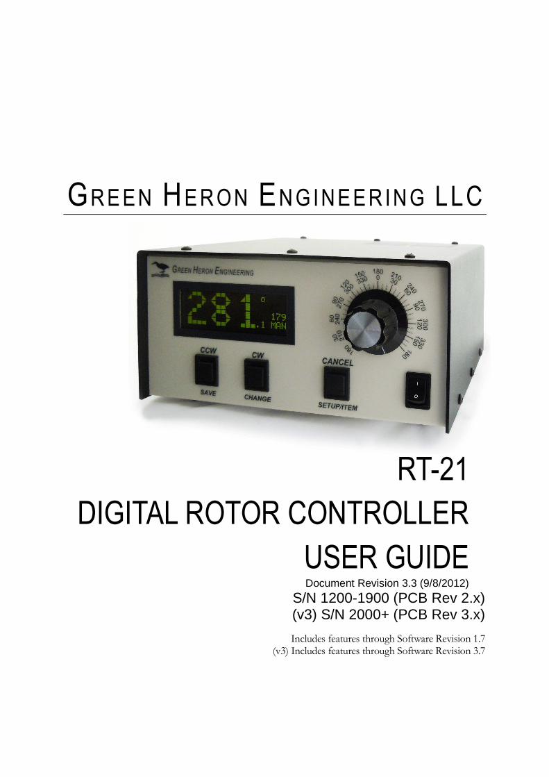
GREEN HERON ENGINEERING LLC
RT-21
DIGITAL ROTOR CONTROLLER
USER GUIDE Document Revision 3.3 (9/8/2012)
S/N 1200-1900 (PCB Rev 2.x) (v3) S/N 2000+ (PCB Rev 3.x)
Includes features through Software Revision 1.7
(v3) Includes features through Software Revision 3.7
2012Green Heron Engineering LLC
1107 Salt Road, Webster, NY 14580 Phone 585.217.9093
www.GreenHeronEngineering.com
RADIO AND TELEVISION INTERFERENCE
This equipment has been tested and found to comply with the limits for a Class B digital device, pursuant to Part 15 of the FCC rules. These limits are designed to provide reasonable protection against harmful interference in a residential installation. This equipment generates, uses and can radiate radio frequency energy and, if not installed and used in accordance with the instructions, may cause harmful interference to radio communications. However, there is no guarantee that interference will not occur in a particular installation. If this equipment does cause harmful interference to radio or television reception, which can be determined by turning the equipment off and on, the user is encouraged to try to correct the interference by one or more of the following measures:
Reorient or relocate the receiving antenna.
Increase the separation between the equipment and the receiver.
Connect the equipment into an outlet on a circuit different from that to which the receiver is connected.
Consult the dealer or an experienced radio/TV technician for help.
You may also find helpful the following booklet, prepared by the FCC: "How to Identify and Resolve Radio-TV Interference Problems." This booklet is available from the U.S. Government Printing Office, Washington D.C. 20402.
Changes and Modifications not expressly approved by the manufacturer or registrant of this equipment can void your authority to operate this equipment under Federal Communications Commissions rules.
NOTICE
The RT-21 may not be certified or recommended by some rotor manufacturers for use with their products. Use of this device may void the warranty of these devices and Green Heron Engineering LLC is not responsible for any damage, direct or incidental, that might occur through such use.
Green Heron Engineering reserves the right to make changes for product improvement or manufacturing, without notice or any obligation to update units already sold.
WARRANTY
This product is warranted to be free of defects in materials and workmanship for 1 year. We will repair or replace, at our option, any equipment proven to be defective within the warranty period. All warranty work is F.O.B. Webster, NY, USA. This warranty is exclusive of abuse, misuse, accidental damage, acts of God or consequential damages, etc. Green Heron Engineering LLC liability shall not exceed the original purchase price of the equipment.
TRADEMARKS
M2 Orion is a trademark of M2 Antenna Systems, Inc.
TIC RingRotor is a registered trademark of TIC General, Inc.
Hy-Gain is a trademark of Hy-Gain Corporation
Yaesu is a trademark of Yaesu/Vertex Standard USA
All other products, company names, brand names, and trademarks are the property of their respective owners.
This unit is normally supplied with a 3 Amp 5x20 mm fuse in the rear panel fuse holder.
If it is necessary, replace only with: 115 VAC – 3 amp max 230 VAC – 1.5 amp max
Table of Contents
IDENTIFYING A V3 – RT-21 .................................................................................................................................................. III 1.0 QUICK START GUIDE ................................. ................................................................................................................ 1
1.1 JUMPERS AND SETTINGS ....................................................................................................................................... 3 1.2 SET THE OFFSET VALUE ....................................................................................................................................... 4 1.3 CONNECT THE RT-21 TO YOUR ROTOR .............................................................................................................. 5 1.4 CALIBRATE YOUR ROTOR ..................................................................................................................................... 5
2.0 FRONT PANEL CONTROLS & DISPLAY .................... .............................................................................................. 6 2.1 FRONT PANEL CONTROLS .................................................................................................................................... 6 2.2 FRONT PANEL DISPLAY ......................................................................................................................................... 9
3.0 SETUP MODE ............................................................................................................................................................ 10 3.1 OPTION PARAMETER ........................................................................................................................................... 10 3.2 SETTING OTHER PARAMETERS ......................................................................................................................... 11
4.0 CALIBRATION ....................................... .................................................................................................................... 15 4.1 POTENTIOMETER SYSTEMS ............................................................................................................................... 15 4.2 PULSE COUNTER SYSTEMS ............................................................................................................................... 16
5.0 OPERATING HINTS & ADVANCED FEATURES ............... ..................................................................................... 17 5.1 OPERATING HINTS 17
5.2 COMPUTER CONTROL OF RT-21 ........................................................................................................................ 18 5.3 CALIBRATION OF SIDEARM INSTALLATION ..................................................................................................... 19 5.4 MASTER/SLAVE (M/S) MODE ............................................................................................................................... 19 5.5 M/C AND S/C MODES .............................................................................................................................................. 20 5.6 DEBUG MODE ......................................................................................................................................................... 21 5.7 FIRMWARE UPDATES (SEE PAGE III FOR RT-21 V3 INFORMATION) ....................................................................... 21 5.8 CHANGING THE VANITY DISPLAY, MOTION TIMEOUT, SECURITY LOCK .................................................... 22 5.9 ALTERNATE OFFSETS (FIRMWARE 1.6 AND LATER) ............................................................................................. 22 5.10 ADVANCED OPTIONS (FIRMWARE 1.6 AND LATER) ........................................................................................... 22
APPENDIX A.1 - TIC RINGROTOR ...................... ............................................................................................................... 24 APPENDIX A.2 – ORION 2300 (ORIGINAL) .............. ......................................................................................................... 25 APPENDIX A.3 – ORION 2800 (AC) .................... ................................................................................................................ 26 APPENDIX A.4 – ORION 2800 DC ...................... ................................................................................................................ 27 APPENDIX A.5 – CREATE RC5 SERIES .................. .......................................................................................................... 28 APPENDIX A.6 – HY-GAIN HAMX, T 2X .............................................................................................................................. 29 APPENDIX A.7 – YAESU G800S, DXA, 1000S, DXA, 2700SD X, 2800DXA ETC. ........................................................... 30 APPENDIX A.8 - SPID ............................... ........................................................................................................................... 31 APPENDIX A.9 - HY-GAIN HDR-300 .................... ............................................................................................................... 32 APPENDIX A.10 – ALLIANCE HD-73 .................... ............................................................................................................. 33 APPENDIX A.11 – ROTOR DOCTOR RD-1800 .............. .................................................................................................... 34 APPENDIX A.12 – YAESU G-450/650XL ................. ........................................................................................................... 35 APPENDIX A.13 – PROSISTEL ‘D’ ..................... ................................................................................................................ 36 APPENDIX A.14 – DIAWA MR-750/MR-300 ............... ........................................................................................................ 37 APPENDIX B – UNIVERSAL ROTOR SETUP INFORMATION .... ..................................................................................... 38 APPENDIX C – EXTERNAL RELAY CONTROL ............... ................................................................................................. 39 APPENDIX D – RT-21 SCHEMATIC ...................... .............................................................................................................. 40 APPENDIX E – ERROR MESSAGES ....................... ........................................................................................................... 41 APPENDIX F – COMMUNICATIONS PROTOCOL .............. ............................................................................................... 42 APPENDIX G – SETUP UTILITY......................... ................................................................................................................. 43
V E R S I O N 3 I N F 0 R M A T I O N :
iii
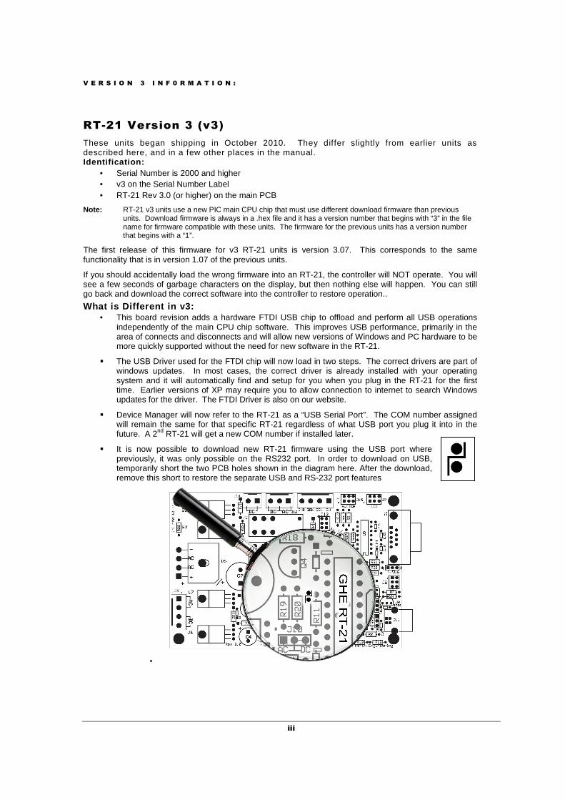
RT-21 Version 3 (v3)
These units began shipping in October 2010. They differ slightly from earlier units as described here, and in a few other places in the manual. Identification:
• Serial Number is 2000 and higher • v3 on the Serial Number Label • RT-21 Rev 3.0 (or higher) on the main PCB
Note: RT-21 v3 units use a new PIC main CPU chip that must use different download firmware than previous units. Download firmware is always in a .hex file and it has a version number that begins with “3” in the file name for firmware compatible with these units. The firmware for the previous units has a version number that begins with a “1”.
The first release of this firmware for v3 RT-21 units is version 3.07. This corresponds to the same functionality that is in version 1.07 of the previous units.
If you should accidentally load the wrong firmware into an RT-21, the controller will NOT operate. You will see a few seconds of garbage characters on the display, but then nothing else will happen. You can still go back and download the correct software into the controller to restore operation..
What is Different in v3: • This board revision adds a hardware FTDI USB chip to offload and perform all USB operations
independently of the main CPU chip software. This improves USB performance, primarily in the area of connects and disconnects and will allow new versions of Windows and PC hardware to be more quickly supported without the need for new software in the RT-21.
� The USB Driver used for the FTDI chip will now load in two steps. The correct drivers are part of windows updates. In most cases, the correct driver is already installed with your operating system and it will automatically find and setup for you when you plug in the RT-21 for the first time. Earlier versions of XP may require you to allow connection to internet to search Windows updates for the driver. The FTDI Driver is also on our website.
� Device Manager will now refer to the RT-21 as a “USB Serial Port”. The COM number assigned will remain the same for that specific RT-21 regardless of what USB port you plug it into in the future. A 2nd RT-21 will get a new COM number if installed later.
� It is now possible to download new RT-21 firmware using the USB port where previously, it was only possible on the RS232 port. In order to download on USB, temporarily short the two PCB holes shown in the diagram here. After the download, remove this short to restore the separate USB and RS-232 port features
•
R T – 2 1 Q U I C K S T A R T G U I D E
1
1.0 QUICK START GUIDE
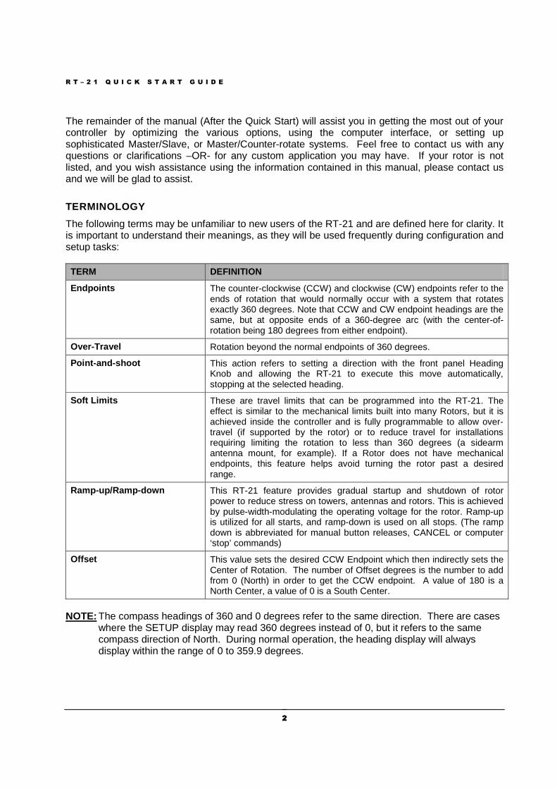
I f your rotor does not have mechanical l imi ts, DO N OT attempt rotat ion other than wi th the CW and CCW pushbuttons before cal ibrat ion has been completed, and the sof t l imi ts are proven to be working as desi red.
NOTE: Additional documentation and optional software are available on our website at www.greenheronengineering,com/support .
Sect ion
1 IMPORTANT - Please Read This! This Section of the manual will assist you in getting your new controller running as fast as possible. Everything you need to know to get your unit setup and running is contained in this QUICK START GUIDE along with the single page in the APPENDIX A that corresponds to your particular Rotor. The current version of SETUP UTILITY program can be found on our webstite and can be used to test your rotor, operate it, or optionally provide a quick calibration for many rotor types. See Appendix ‘H’ for SETUP UTILITY capabilities and instructions.
If Green Heron Engineering DID NOT configure your controller OR you are changing to a different type of rotor perform the steps in Section 1.1 Jumpers and Settings (page 2)
If Green Heron Engineering configured your controller for your rotor type, skip the steps in Section 1.1. They have been completed for you.
Next perform the following steps as defined in this guide.
• Section 1.2 Set the Offset Value (page 4) Set your OFFSET (only if you do not want a North Center which is the default)
• Section 1.3 Connect the RT-21 to Your Rotor (page 5) Hook your rotor to the rear terminal strip per the instructions for your rotor type.
• Section 1.4 Calibrate Your Rotor (page 5)
As a quick alternative, you may use the Auto-Cal facility of the SETUP UTILITY described in appendix G. The Pot Auto-Cal, although considered an estimate, may be accurate enough for most needs. The Orion Auto-Cal is recommended and accurate for Orion rotors.
R T – 2 1 Q U I C K S T A R T G U I D E
2 2
The remainder of the manual (After the Quick Start) will assist you in getting the most out of your controller by optimizing the various options, using the computer interface, or setting up sophisticated Master/Slave, or Master/Counter-rotate systems. Feel free to contact us with any questions or clarifications –OR- for any custom application you may have. If your rotor is not listed, and you wish assistance using the information contained in this manual, please contact us and we will be glad to assist.
TERMINOLOGY
The following terms may be unfamiliar to new users of the RT-21 and are defined here for clarity. It is important to understand their meanings, as they will be used frequently during configuration and setup tasks:
TERM DEFINITION
Endpoints The counter-clockwise (CCW) and clockwise (CW) endpoints refer to the ends of rotation that would normally occur with a system that rotates exactly 360 degrees. Note that CCW and CW endpoint headings are the same, but at opposite ends of a 360-degree arc (with the center-of-rotation being 180 degrees from either endpoint).
Over-Travel Rotation beyond the normal endpoints of 360 degrees.
Point-and-shoot This action refers to setting a direction with the front panel Heading Knob and allowing the RT-21 to execute this move automatically, stopping at the selected heading.
Soft Limits These are travel limits that can be programmed into the RT-21. The effect is similar to the mechanical limits built into many Rotors, but it is achieved inside the controller and is fully programmable to allow over-travel (if supported by the rotor) or to reduce travel for installations requiring limiting the rotation to less than 360 degrees (a sidearm antenna mount, for example). If a Rotor does not have mechanical endpoints, this feature helps avoid turning the rotor past a desired range.
Ramp-up/Ramp-down This RT-21 feature provides gradual startup and shutdown of rotor power to reduce stress on towers, antennas and rotors. This is achieved by pulse-width-modulating the operating voltage for the rotor. Ramp-up is utilized for all starts, and ramp-down is used on all stops. (The ramp down is abbreviated for manual button releases, CANCEL or computer ‘stop’ commands)
Offset This value sets the desired CCW Endpoint which then indirectly sets the Center of Rotation. The number of Offset degrees is the number to add from 0 (North) in order to get the CCW endpoint. A value of 180 is a North Center, a value of 0 is a South Center.
NOTE: The compass headings of 360 and 0 degrees refer to the same direction. There are cases where the SETUP display may read 360 degrees instead of 0, but it refers to the same compass direction of North. During normal operation, the heading display will always display within the range of 0 to 359.9 degrees.
R T – 2 1 Q U I C K S T A R T G U I D E
3 3
1.1 JUMPERS and SETTINGS
(YOU MAY SKIP to paragraph 1.2 ONLY if we’ve pre-configured your unit)
1.1.1 RT-21 Hardware Configuration (Internal Jumper s and Wiring Options) 1. Ensure that the power cable is disconnected from the rear panel of the RT-21. 2. Remove the twelve Phillips head screws securing the top cover and remove the
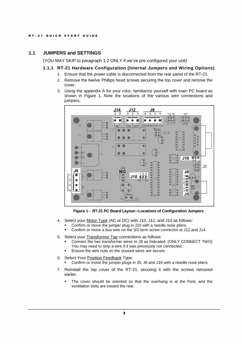
cover. 3. Using the appendix A for your rotor, familiarize yourself with main PC board as
shown in Figure 1. Note the locations of the various wire connections and jumpers.
Figure 1 - RT-21 PC Board Layout—Locations of Conf iguration Jumpers
4. Select your Motor Type (AC or DC) with J10, J12, and J14 as follows: � Confirm or move the jumper plug in J10 with a needle nose pliers. � Confirm or move a bus wire on the 3/2 term screw connector at J12 and J14.
5. Select your Transformer Tap connections as follows: � Connect the two transformer wires to J9 as indicated. (ONLY CONNECT TWO)
You may need to strip a wire if it was previously not connected. � Ensure the wire nuts on the unused wires are secure.
6. Select Your Position Feedback Type: � Confirm or move the jumper plugs in J5, J6 and J16 with a needle nose pliers.
7. Reinstall the top cover of the RT-21, securing it with the screws removed earlier.
� The cover should be oriented so that the overhang is at the front, and the ventilation slots are toward the rear.
R T – 2 1 Q U I C K S T A R T G U I D E
4 4
8. Verify that the 115/230 VAC switch on the rear panel is set properly. � This switch MUST be set to the choice that is correct for the primary (mains)
voltage that will power your RT-21. A small screwdriver may be used to move the switch, if necessary.
� If the position of the 115/230 VAC switch is moved, check the rear panel fuse for proper value. The fuse is an International Standard GMA 5mm x 20mm type, and should normally be a 3A fuse for 115 VAC line, or a 1.5A fuse for 230 VAC line.
9. Connect the power cord to the rear panel receptacle and set the front panel power switch to ON. You should first see the user vanity message, then the software version number, followed by the operating display.
1.1.2 RT-21 Software Configuration (Software SETTIN GS)
This procedure assumes that the SETUP parameters are all at factory default. If you wish to assure this condition, press and hold CANCEL + CCW + CW as described in 2.1.5 until the display indicates RESET EE. (Or use SETUP Utility)
The correct OPTION for your Rotor must be selected and saved prior to changing any other items in SETUP.
Before making this selection, ensure that all hardw are jumpers have been made as described above
1. Go into SETUP Mode as follows: � Press and hold the SETUP/ITEM button until SETUP appears on the display. � Choose the OPTION parameter by repeatedly pressing and releasing the
SETUP/ITEM button until the display shows OPTION.
2. Choose the correct OPTION by rotating the heading knob until the “New Value = “ the correct option for your rotor, as defined in the Appendix A., is displayed. � POT – 2 or 3-wire potentiometer or variable resistor - generic � COUNTER – Pulse Counter - generic � HAMx – HAM-X Hy-Gain® Rotor with separate wedge brake control � T2X – T2X Hy-Gain® Rotor with separate wedge brake control* � TIC-PST – TIC RingRotors or Prosistel � ORION – M2 Orion rotor, DC motor type with 3960 Pulse/360 degrees � SPID – Alfa Spid types with 1 pulse/degree
3. When the correct option for your Rotor is displayed, save it as follows: � Press the CHANGE button to change it. � Press the SAVE button to store the change and exit.
1.2 SET THE OFFSET VALUE
The offset value is the number of degrees that your counter-clockwise (CCW) endpoint is from true North. It is normally equal to the compass heading of your CCW endpoint. This might be a different value than your CCW mechanical stop if your rotor has wider rotation than 360 degrees.
Offset can also be viewed as the desired center-of-rotation (180°) clockwise from North.
R T – 2 1 Q U I C K S T A R T G U I D E
5 5
For example: If your center-of-rotation were South (with the CCW endpoint at North) then your offset would be 0. If your center-of-rotation were North (with your CCW endpoint at South) then your offset would be 180 degrees (Default).
1.2.1 Configure the desired Offset value 1. Enter SETUP mode
• Press and hold down the SETUP/ITEM button for 2 seconds • Release the SETUP/ITEM button when SETUP appears on the display.
2. Choose the OFFSET parameter • Repeatedly press and release the SETUP ITEM button until Offset is displayed
o The currently set offset will be displayed after the equals sign (=). o The bottom line on the display will indicate NEW VALUE = XXX .
3. Set the OFFSET parameter for your rotor • Rotate the heading knob until the desired OFFSET is displayed after NEW VALUE
= on the display.
NOTE: For North Center – OFFSET = 180 degrees (Default) For South Center – OFFSET = 0 degrees
• Press the CHANGE button to store the New OPTION. • Press the SAVE button to save the option and exit the SETUP menu.
1.3 CONNECT THE RT-21 TO YOUR ROTOR
R e m o v e p o w e r f r o m t h e u n i t b e f o r e m a k i n g r o t o r c o n n e c t i o n s
1.3.1 Connect your Rotor to the rear panel terminal strip of the RT-21 using the chart labeled “Rotor Connections” in the appendix ‘A’ for your rotor. The first column of terminal numbers refers to the terminal numbers of the rotor’s factory controller or the rotor itself. The terminal numbers under the RT-21 column are the correct RT-21 terminals for the same wire.
1.4 CALIBRATE YOUR ROTOR
DO NOT use the Point-and-Shoot knob before your rotor is fully calibrated .
Rotors without mechanical limits may be damaged or rotor loops may be exceeded if unintended over-travel occurs.
If your rotor does not have mechanical stops at 360 degrees of rotation, insure that you or a helper is positioned to watch antenna travel during calibration
1.4.1 Calibrate according to the specific instructions in the Appendix ‘A’ for your rotor. The heading directions when referred to (North or South) in these procedures assume a North center (the default offset). If you have changed the OFFSET from the default for a South center, then the directions in (parentheses) should be used instead
F R O N T P A N E L C O N T R O L S & D I S P L A Y
6
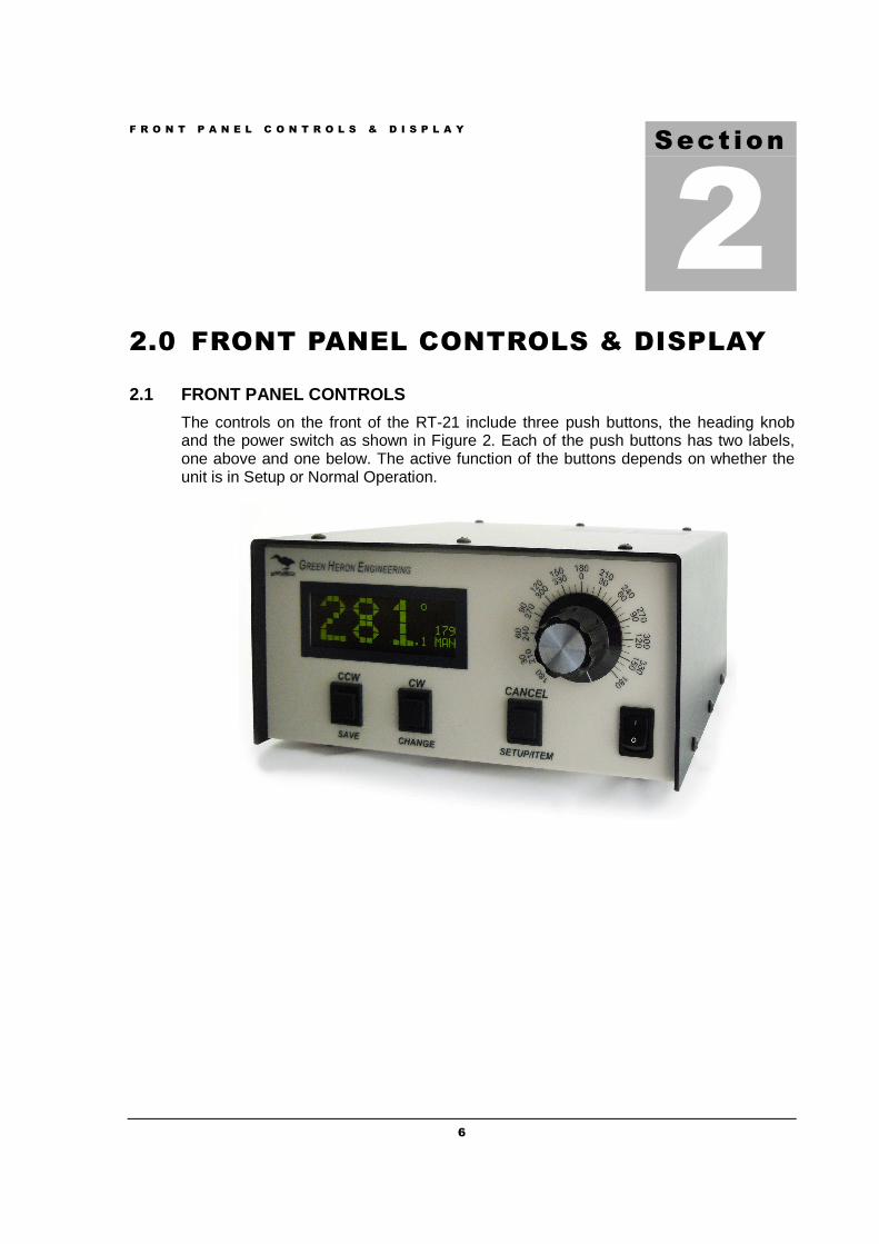
2.0 FRONT PANEL CONTROLS & DISPLAY
2.1 FRONT PANEL CONTROLS
The controls on the front of the RT-21 include three push buttons, the heading knob and the power switch as shown in Figure 2. Each of the push buttons has two labels, one above and one below. The active function of the buttons depends on whether the unit is in Setup or Normal Operation.
Sect ion
2
F R O N T P A N E L C O N T R O L S A N D D I S P L A Y
7
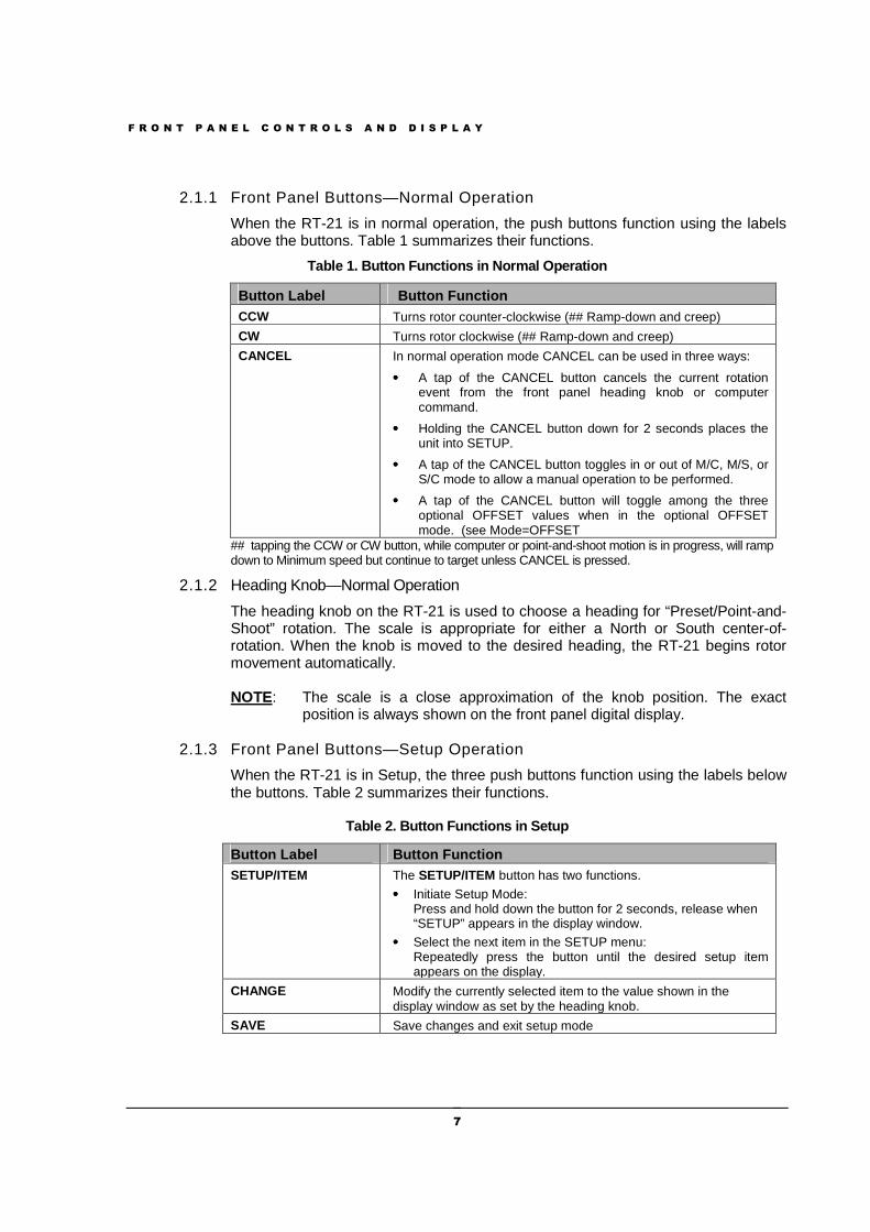
2.1.1 Front Panel Buttons—Normal Operation
When the RT-21 is in normal operation, the push buttons function using the labels above the buttons. Table 1 summarizes their functions.
Table 1. Button Functions in Normal Operation
Button Label Button Function CCW Turns rotor counter-clockwise (## Ramp-down and creep)
CW Turns rotor clockwise (## Ramp-down and creep)
CANCEL In normal operation mode CANCEL can be used in three ways:
•••• A tap of the CANCEL button cancels the current rotation event from the front panel heading knob or computer command.
•••• Holding the CANCEL button down for 2 seconds places the unit into SETUP.
•••• A tap of the CANCEL button toggles in or out of M/C, M/S, or S/C mode to allow a manual operation to be performed.
•••• A tap of the CANCEL button will toggle among the three optional OFFSET values when in the optional OFFSET mode. (see Mode=OFFSET
## tapping the CCW or CW button, while computer or point-and-shoot motion is in progress, will ramp down to Minimum speed but continue to target unless CANCEL is pressed.
2.1.2 Heading Knob—Normal Operation
The heading knob on the RT-21 is used to choose a heading for “Preset/Point-and-Shoot” rotation. The scale is appropriate for either a North or South center-of-rotation. When the knob is moved to the desired heading, the RT-21 begins rotor movement automatically.
NOTE: The scale is a close approximation of the knob position. The exact position is always shown on the front panel digital display.
2.1.3 Front Panel Buttons—Setup Operation
When the RT-21 is in Setup, the three push buttons function using the labels below the buttons. Table 2 summarizes their functions.
Table 2. Button Functions in Setup
Button Label Button Function SETUP/ITEM The SETUP/ITEM button has two functions.
•••• Initiate Setup Mode: Press and hold down the button for 2 seconds, release when “SETUP” appears in the display window.
•••• Select the next item in the SETUP menu: Repeatedly press the button until the desired setup item appears on the display.
CHANGE Modify the currently selected item to the value shown in the display window as set by the heading knob.
SAVE Save changes and exit setup mode
F R O N T P A N E L C O N T R O L S A N D D I S P L A Y
8
2.1.4 Heading Knob—Setup Operation
When in SETUP, the Heading Knob is used to select desired values on the display.
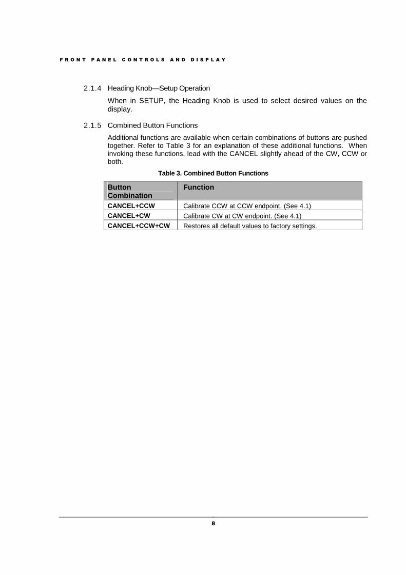
2.1.5 Combined Button Functions
Additional functions are available when certain combinations of buttons are pushed together. Refer to Table 3 for an explanation of these additional functions. When invoking these functions, lead with the CANCEL slightly ahead of the CW, CCW or both.
Table 3. Combined Button Functions
Button Combination
Function
CANCEL+CCW Calibrate CCW at CCW endpoint. (See 4.1)
CANCEL+CW Calibrate CW at CW endpoint. (See 4.1)
CANCEL+CCW+CW Restores all default values to factory settings.
F R O N T P A N E L C O N T R O L S A N D D I S P L A Y
9
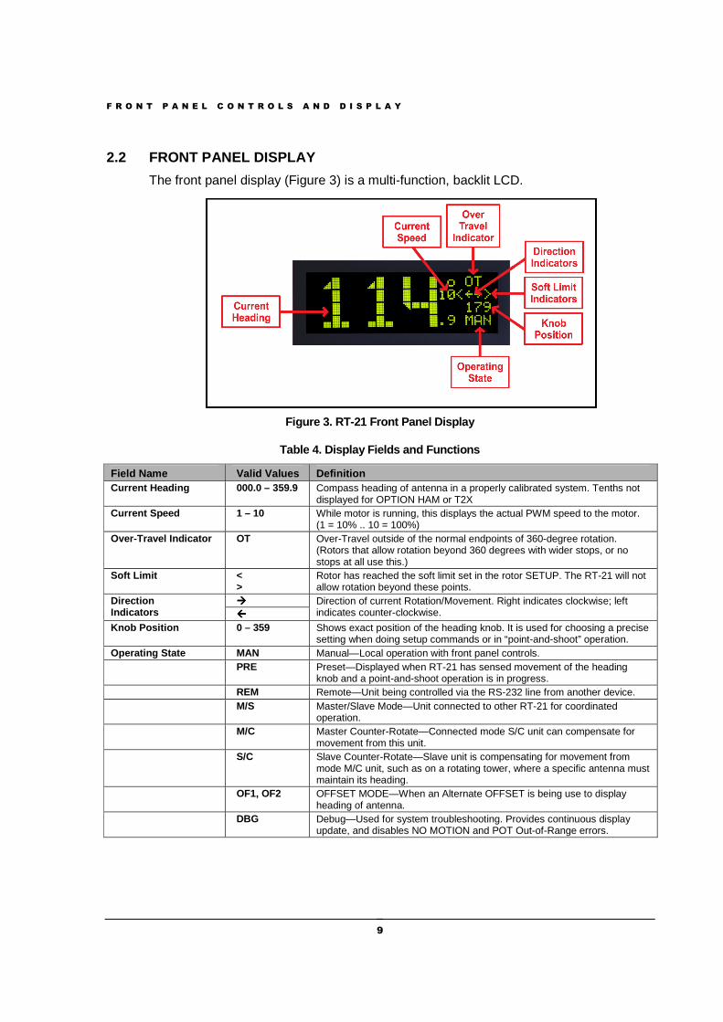
2.2 FRONT PANEL DISPLAY
The front panel display (Figure 3) is a multi-function, backlit LCD.
Figure 3. RT-21 Front Panel Display
Table 4. Display Fields and Functions
Field Name Valid Values Definition Current Heading 000.0 – 359.9 Compass heading of antenna in a properly calibrated system. Tenths not
displayed for OPTION HAM or T2X Current Speed 1 – 10 While motor is running, this displays the actual PWM speed to the motor.
(1 = 10% .. 10 = 100%) Over-Travel Indicator OT Over-Travel outside of the normal endpoints of 360-degree rotation.
(Rotors that allow rotation beyond 360 degrees with wider stops, or no stops at all use this.)
Soft Limit < >
Rotor has reached the soft limit set in the rotor SETUP. The RT-21 will not allow rotation beyond these points.
Direction Indicators
���� Direction of current Rotation/Movement. Right indicates clockwise; left indicates counter-clockwise.
Knob Position 0 – 359 Shows exact position of the heading knob. It is used for choosing a precise setting when doing setup commands or in “point-and-shoot” operation.
Operating State MAN Manual—Local operation with front panel controls. PRE Preset—Displayed when RT-21 has sensed movement of the heading
knob and a point-and-shoot operation is in progress. REM Remote—Unit being controlled via the RS-232 line from another device. M/S Master/Slave Mode—Unit connected to other RT-21 for coordinated
operation. M/C Master Counter-Rotate—Connected mode S/C unit can compensate for
movement from this unit. S/C Slave Counter-Rotate—Slave unit is compensating for movement from
mode M/C unit, such as on a rotating tower, where a specific antenna must maintain its heading.
OF1, OF2 OFFSET MODE—When an Alternate OFFSET is being use to display heading of antenna.
DBG Debug—Used for system troubleshooting. Provides continuous display update, and disables NO MOTION and POT Out-of-Range errors.
S E T U P M O D E
10
3.0 SETUP MODE
The RT-21 rotor controller allows you to program virtually every aspect of your rotor’s operation. The controller’s SETUP menu is used to set all operating parameters.
The first setup task is to select the OPTION parameter. This prepares the controller for the requirements of your rotor system.
The correct OPTION for your Rotor must be selected and saved prior to changing any other items in SETUP
3.1 OPTION PARAMETER
The OPTION parameter setting provides the correct startup conditions for your system and makes items that pertain to your rotor accessible in the SETUP menu.
The RT-21 supports the following OPTION values:
POT – 2 or 3-wire potentiometer or variable resistor. The POT option uses the potentiometer method of determining the position of the rotor. The RT-21 reads the voltage on the wiper of the potentiometer using a precision A/D converter and displays the result in degrees.
COUNTER – Pulse Counter The COUNTER option uses the “pulse counter” method of determining the position of the rotor. A reed or proximity switch generates pulses, which are read and counted by the RT-21. This count is used to calculate the current position of the Rotor in degrees.
HAMx – HAM-X Hy-Gain® Rotor with separate wedge brake control. The RT-21 uses half the potentiometer in these rotors because the wiper is grounded. The software smoothes out the readings during A/D conversion for HAM-style rotors.
T2X – Tailtwister (T2X) Hy-Gain® Rotor with separate wedge brake control. This OPTION is very similar to the HAMx option EXCEPT that it adds automatic motor reversals to help eliminate the inherent “brake stick” problem in these units. Prior to starting a Point and Shoot or a computer generated motion, the RT-21 will momentarily run the unit in the opposite of the intended direction to relieve any back tension on the BRAKE in order to help it release properly. Also, the RT-21 will try to
Sect ion
3
S E T U P M O D E
11
prevent the T2X rotor from going all the way to the end stop so that the limit switch won’t disable this reversal.
TIC-PST TIC RingRotor or Prosistel This OPTION is the same as the POT option EXCEPT that it adds an additional safety mechanism to prevent these rotors from running beyond their pot limits and causing motor damage. These rotors have no mechanical limiting switches and their POT arrangement is such that they never need to run near either end of the POT. The RT-21 limits the operation of these rotors to the middle 88% of the POT range and will display a POT OUT-OF-RANGE error if it gets near either end. This error can be overridden by using MODE = DEBUG.
ORION – M2 Orion (Pulse System units) This OPTION is the same as the COUNTER option EXCEPT that it sets the Pulse Divider HI and LO to the correct 3960 value automatically. Also sets the Soft Limits to +/- 14 degrees of over-travel that this unit allows.
SPID – Alfa Spid Rotors This OPTION is the same as the COUNTER option EXCEPT that it sets the Pulse Divider HI and LO to the correct 360 value automatically.
To setup the OPTION parameter, perform the followin g steps: 1. Enter SETUP mode
• Press and hold down the SETUP/ITEM button for 2 seconds • Release the SETUP/ITEM button when SETUP appears on the display.
2. Choose the OPTION parameter • Repeatedly press and release the SETUP ITEM button until SETUP-OPTION =
is displayed o The currently set option will be displayed after the equals sign (=). o The bottom line on the display will indicate NEW VALUE = XXX .
3. Set the OPTION parameter for your rotor • Rotate the heading knob until the desired OPTION is displayed after NEW
VALUE = on the display. • Press the CHANGE button to store the New OPTION. • Press the SAVE button to save the option and exit the SETUP menu.
3.2 SETTING OTHER PARAMETERS
This same sequence that was used to set up the OPTION parameter is used to modify any setup parameter (SELECT, CHANGE, SAVE).
It is important to remember that if you change an OPTION parameter, you must SAVE and reenter the SETUP menu to make any other changes
TIP: Some menu items can change calculations and affect related options, so it’s a good idea to only change one item at a time until you become familiar with the RT-21. For example, changing the CTR divide ratios will change the CALIBRATE , the OFFSET will change the SOFT LIMITS to match, etc.
S E T U P M O D E
12
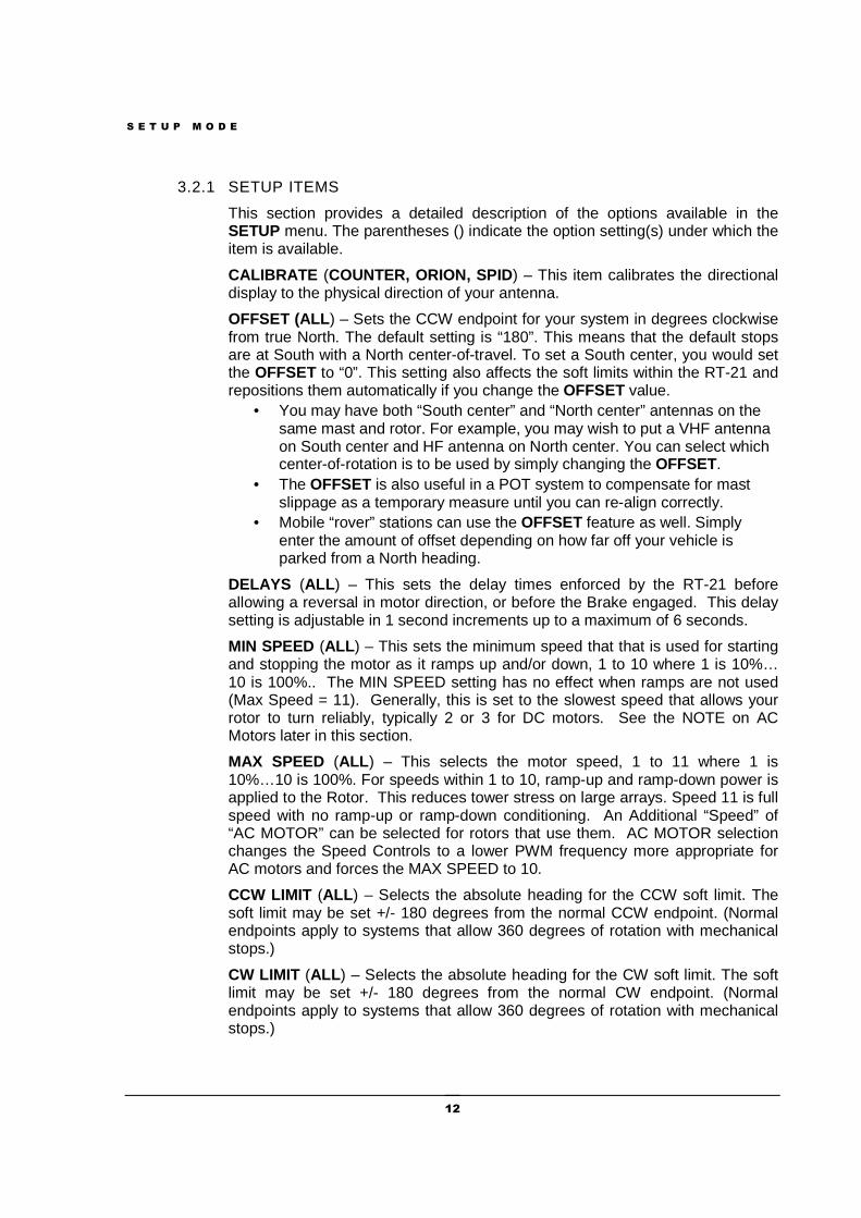
3.2.1 SETUP ITEMS
This section provides a detailed description of the options available in the SETUP menu. The parentheses () indicate the option setting(s) under which the item is available.
CALIBRATE (COUNTER, ORION, SPID) – This item calibrates the directional display to the physical direction of your antenna.
OFFSET (ALL ) – Sets the CCW endpoint for your system in degrees clockwise from true North. The default setting is “180”. This means that the default stops are at South with a North center-of-travel. To set a South center, you would set the OFFSET to “0”. This setting also affects the soft limits within the RT-21 and repositions them automatically if you change the OFFSET value.
• You may have both “South center” and “North center” antennas on the same mast and rotor. For example, you may wish to put a VHF antenna on South center and HF antenna on North center. You can select which center-of-rotation is to be used by simply changing the OFFSET.
• The OFFSET is also useful in a POT system to compensate for mast slippage as a temporary measure until you can re-align correctly.
• Mobile “rover” stations can use the OFFSET feature as well. Simply enter the amount of offset depending on how far off your vehicle is parked from a North heading.
DELAYS (ALL ) – This sets the delay times enforced by the RT-21 before allowing a reversal in motor direction, or before the Brake engaged. This delay setting is adjustable in 1 second increments up to a maximum of 6 seconds.
MIN SPEED (ALL ) – This sets the minimum speed that that is used for starting and stopping the motor as it ramps up and/or down, 1 to 10 where 1 is 10%… 10 is 100%.. The MIN SPEED setting has no effect when ramps are not used (Max Speed = 11). Generally, this is set to the slowest speed that allows your rotor to turn reliably, typically 2 or 3 for DC motors. See the NOTE on AC Motors later in this section.
MAX SPEED (ALL ) – This selects the motor speed, 1 to 11 where 1 is 10%…10 is 100%. For speeds within 1 to 10, ramp-up and ramp-down power is applied to the Rotor. This reduces tower stress on large arrays. Speed 11 is full speed with no ramp-up or ramp-down conditioning. An Additional “Speed” of “AC MOTOR” can be selected for rotors that use them. AC MOTOR selection changes the Speed Controls to a lower PWM frequency more appropriate for AC motors and forces the MAX SPEED to 10.
CCW LIMIT (ALL ) – Selects the absolute heading for the CCW soft limit. The soft limit may be set +/- 180 degrees from the normal CCW endpoint. (Normal endpoints apply to systems that allow 360 degrees of rotation with mechanical stops.)
CW LIMIT (ALL ) – Selects the absolute heading for the CW soft limit. The soft limit may be set +/- 180 degrees from the normal CW endpoint. (Normal endpoints apply to systems that allow 360 degrees of rotation with mechanical stops.)
S E T U P M O D E
13
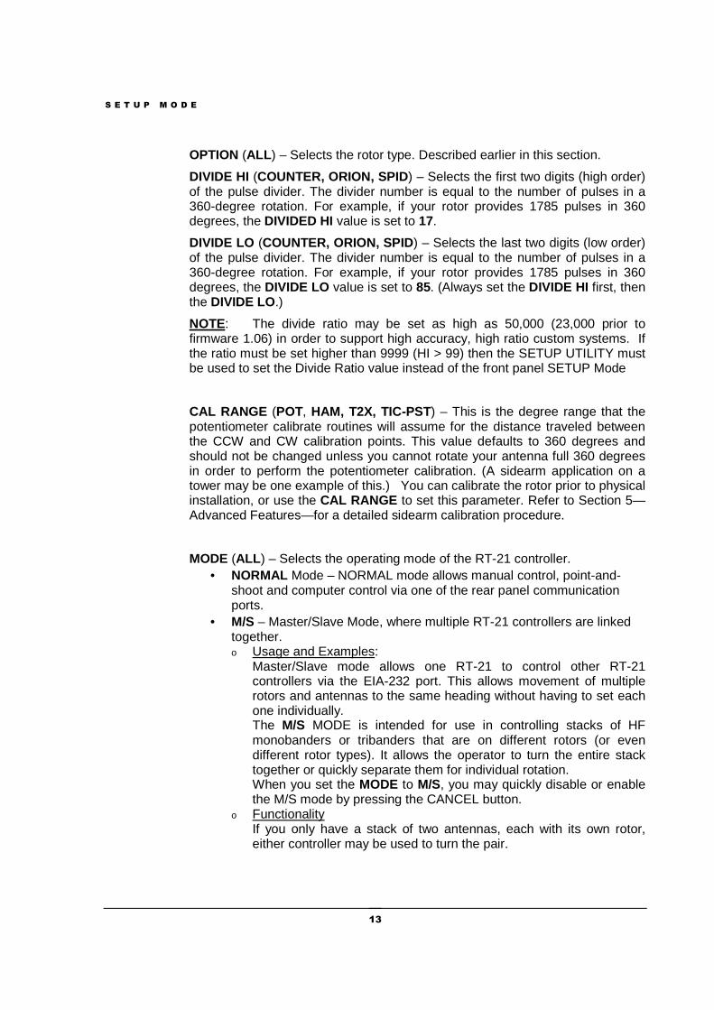
OPTION (ALL ) – Selects the rotor type. Described earlier in this section.
DIVIDE HI (COUNTER, ORION, SPID) – Selects the first two digits (high order) of the pulse divider. The divider number is equal to the number of pulses in a 360-degree rotation. For example, if your rotor provides 1785 pulses in 360 degrees, the DIVIDED HI value is set to 17.
DIVIDE LO (COUNTER, ORION, SPID) – Selects the last two digits (low order) of the pulse divider. The divider number is equal to the number of pulses in a 360-degree rotation. For example, if your rotor provides 1785 pulses in 360 degrees, the DIVIDE LO value is set to 85. (Always set the DIVIDE HI first, then the DIVIDE LO.)
NOTE: The divide ratio may be set as high as 50,000 (23,000 prior to firmware 1.06) in order to support high accuracy, high ratio custom systems. If the ratio must be set higher than 9999 (HI > 99) then the SETUP UTILITY must be used to set the Divide Ratio value instead of the front panel SETUP Mode
CAL RANGE (POT, HAM, T2X, TIC-PST) – This is the degree range that the potentiometer calibrate routines will assume for the distance traveled between the CCW and CW calibration points. This value defaults to 360 degrees and should not be changed unless you cannot rotate your antenna full 360 degrees in order to perform the potentiometer calibration. (A sidearm application on a tower may be one example of this.) You can calibrate the rotor prior to physical installation, or use the CAL RANGE to set this parameter. Refer to Section 5—Advanced Features—for a detailed sidearm calibration procedure.
MODE (ALL ) – Selects the operating mode of the RT-21 controller. • NORMAL Mode – NORMAL mode allows manual control, point-and-
shoot and computer control via one of the rear panel communication ports.
• M/S – Master/Slave Mode, where multiple RT-21 controllers are linked together. o Usage and Examples:
Master/Slave mode allows one RT-21 to control other RT-21 controllers via the EIA-232 port. This allows movement of multiple rotors and antennas to the same heading without having to set each one individually. The M/S MODE is intended for use in controlling stacks of HF monobanders or tribanders that are on different rotors (or even different rotor types). It allows the operator to turn the entire stack together or quickly separate them for individual rotation. When you set the MODE to M/S, you may quickly disable or enable the M/S mode by pressing the CANCEL button.
o Functionality If you only have a stack of two antennas, each with its own rotor, either controller may be used to turn the pair.
S E T U P M O D E
14
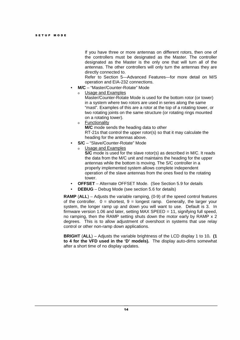
If you have three or more antennas on different rotors, then one of the controllers must be designated as the Master. The controller designated as the Master is the only one that will turn all of the antennas. The other controllers will only turn the antennas they are directly connected to. Refer to Section 5—Advanced Features—for more detail on M/S operation and EIA-232 connections.
• M/C – “Master/Counter-Rotate” Mode o Usage and Examples
Master/Counter-Rotate Mode is used for the bottom rotor (or tower) in a system where two rotors are used in series along the same “mast”. Examples of this are a rotor at the top of a rotating tower, or two rotating joints on the same structure (or rotating rings mounted on a rotating tower).
o Functionality M/C mode sends the heading data to other RT-21s that control the upper rotor(s) so that it may calculate the heading for the antennas above.
• S/C – “Slave/Counter-Rotate” Mode o Usage and Examples
S/C mode is used for the slave rotor(s) as described in M/C. It reads the data from the M/C unit and maintains the heading for the upper antennas while the bottom is moving. The S/C controller in a properly implemented system allows complete independent operation of the slave antennas from the ones fixed to the rotating tower.
• OFFSET – Alternate OFFSET Mode. (See Section 5.9 for details • DEBUG – Debug Mode (see section 5.6 for details)
RAMP (ALL ) – Adjusts the variable ramping, (0-9) of the speed control features of the controller. 0 = shortest, 9 = longest ramp. Generally, the larger your system, the longer ramp up and down you will want to use. Default is 3. In firmware version 1.06 and later, setting MAX SPEED = 11, signifying full speed, no ramping, then the RAMP setting shuts down the motor early by RAMP x 2 degrees. This is to allow adjustment of overshoot in systems that use relay control or other non-ramp down applications.
BRIGHT (ALL ) – Adjusts the variable brightness of the LCD display 1 to 10. (1 to 4 for the VFD used in the ‘D’ models). The display auto-dims somewhat after a short time of no display updates.
C A L I B R A T I O N
15
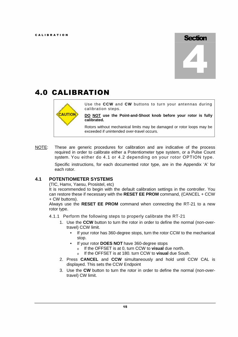
4.0 CALIBRATION
Use the CCW and CW but tons to turn your antennas dur ing ca l ibrat ion steps.
DO NOT use the Point-and-Shoot knob before your rotor is fully calibrated.
Rotors without mechanical limits may be damaged or rotor loops may be exceeded if unintended over-travel occurs.
NOTE: These are generic procedures for calibration and are indicative of the process required in order to calibrate either a Potentiometer type system, or a Pulse Count system. You either do 4.1 or 4.2 depending on your rotor OPTION type.
Specific instructions, for each documented rotor type, are in the Appendix ‘A’ for each rotor.
4.1 POTENTIOMETER SYSTEMS (TIC, Hamx, Yaesu, Prosistel, etc) It is recommended to begin with the default calibration settings in the controller. You can restore these if necessary with the RESET EE PROM command, (CANCEL + CCW + CW buttons). Always use the RESET EE PROM command when connecting the RT-21 to a new rotor type.
4.1.1 Perform the following steps to properly calibrate the RT-21 1. Use the CCW button to turn the rotor in order to define the normal (non-over-
travel) CCW limit. • If your rotor has 360-degree stops, turn the rotor CCW to the mechanical
stop. • If your rotor DOES NOT have 360-degree stops
o If the OFFSET is at 0, turn CCW to visual due north. o If the OFFSET is at 180. turn CCW to visual due South.
2. Press CANCEL and CCW simultaneously and hold until CCW CAL is displayed. This sets the CCW Endpoint
3. Use the CW button to turn the rotor in order to define the normal (non-over-travel) CW limit.
Section
4
C A L I B R A T I O N
16
• If your rotor has 360-degree stops, turn the rotor CW to the mechanical stop.
• If your rotor DOES NOT have 360-degree stops o Use the CW button to turn the rotor exactly 360 degrees until the
antennas are positioned back in the same visual direction as in Step 1 above. This is the CW endpoint.
4. Press CANCEL and CW simultaneously and hold until CW CAL is displayed.
The numbers displayed are the results of the analog-to-digital (A/D) conversion of the voltage read on the potentiometer. They will vary depending on the amount of travel the indicator potentiometer actually moves, but the CCW value should be fairly low and the CW value should be significantly higher. The larger the difference between the two numbers, the higher the resolution of the heading display will be.
A system that only uses 2 turns of a 10- turn pot will not have nearly the resolution of one that uses 8 or 9 turns of the same pot. The accuracy and resolution of the RT-21 controller depends entirely on the amount of change of this A/D reading and the linearity of the potentiometer used. The maximum resolution is about 1/3 degree with this option.
4.2 PULSE COUNTER SYSTEMS
(Orion, SPID)
Ensure that the correct divider value is set with DIVIDE HI and DIVIDE LOW based on the number of pulses in a 360-degree rotation.
Simply turn your antenna to a known direction visually, and then set the OFFSET value to yield the desired end or center-of-rotation headings. Finally, set the CALIBRATE value to the same heading as the antennas are physically pointed.
NOTE: The RT-21 cannot adjust the actual position of your antenna in relation to the physical endstops OR in relation to your coax rotor loops as installed.
O P E R A T I N G H I N T S & A D V A N C E D F E A T U R E S
17
5.0 OPERATING HINTS & ADVANCED FEATURES
5.1 OPERATING HINTS
A review of the Operating Hints below will help you get the most out of your RT-21 and resolve minor difficulties that may be encountered. In addition, Green Heron Engineering is available to assist with any questions you may have about your controller. Use the contact information at the front of this manual to reach us.
1. The voltage taps listed in the configuration charts (Appendix A) are normal settings for short-to-moderate cable runs. If you find that your rotor turns more slowly than usual, or the ramp-down function does not operate correctly, try using the next higher voltage tap on the transformer (i.e., use violet wire instead of orange). Any two wires may be used to connect to J9. e.g. If you connect the Yellow to term 3 and the Orange to term 4, you will get approximately 14 VDC for the motor. The transformer voltage taps are approximately 0, 18, 28, and 38 VAC.
2. Some rotors work better under pulse width-modulated (PWM) speed control than others. In general, DC motors appear to operate better than AC motors in this regard. Also, lightly loaded rotors and heavily loaded rotors behave differently as they are ramped down. Experimentation may be needed with the speed controls, ramp setting and voltage setting to optimize your system. We run the PWM frequency at 1.2 KHz for DC motors, and much lower when the Max Speed is set to “AC MOTOR”.
3. When evaluated with the RT-21, HAMx and T2X rotors exhibited the least effective speed control. For these rotors, we recommend setting the RT-21 to SPEED= 11 to eliminate the PWM control.
4. We recommend that the RT-21 soft limits be set to values that will prevent your rotor from turning into (or possibly through) its mechanical limits. Setting the soft limits to 5 degrees “early” is a good practice and will help avoid this problem. The OPTION = T2X setting does this for you to ensure there is room to reverse the motor prior to running in the correct direction.
5. Rotors without mechanical limits must depend entirely on the controller to prevent rotation beyond the desired range and to prevent damage to your coax and/or potentiometer. The RT-21 incorporates extra protection for these rotors by shutting down the motor Power Supply when the motor should not be turning. This was a user option in older units. (See Appendix ‘D’)
Section
5
O P E R A T I N G H I N T S & A D V A N C E D F E A T U R E S
18
6. Your RT-21 comes set for your rotor type from the factory. (if we know it) If not, the factory defaults are for a 36 VDC motor (mid-voltage) and a potentiometer-positioning indicator system. The offset value is 180, which needs a CCW & CW endpoint of South, and a North center-of-rotation. You can return to these default settings at any time by pressing the CANCEL, CW, and CCW buttons at the same time and holding until the unit resets.
7. The RT-21 is protected by a fuse on the rear panel. If the controller shows no sign of power, the fuse may be blown. The fuse is an International Standard GMA 5mm x 20mm type, and should be replaced with a 3A fuse for 115 VAC operation, or a 1.5A fuse for 230 VAC operation. Replacement fuses are available at most electronics parts distributors, including Radio Shack.
5.2 COMPUTER CONTROL OF RT-21
The RT-21 is equipped with a fully operational RS-232 port and a USB ‘B’ connection. Virtually all programs that support rotor control via a COM port can be used with the RT-21 on either port. The RT-21 USB port implements the standard COM port emulation that works with standard Windows drivers. See 5.2.2 for installation instructions.
The protocol implemented in the RT-21 is based on the Hy-Gain® DCU-1 protocol and runs at 4800 8N1 using a straight through serial cable with at least pins 2-2, 3-3 and 5-5 wired. It reports headings and turns to headings with the same commands implemented in DCU-1. Set your software to use DCU-1 protocol at 4800 8N1 if your program does not have a Green Heron setting. Many additional commands are provided for the advanced features that only your RT-21 can perform. These include the ability to computer track to 1/10th degree using GH Tracker, or operate your controller as part of an IP network using GH Everyware software from Green Heron.
5.2.1 USB Functionality is limited to computer control. You cannot use the USB to interconnect RT-21s for the purpose of Master/Slave, or Counter-rotate functions.
NOTE: The EIA-232 Port (dB-9) MUST be used for interconnection to other RT-20, or RT-21 controllers AND for loading new software updates from Green Heron. (RT-21 v3 allows USB software updates, see page iii)
5.2.2 USB INSTALLATION (Prior to Rt-21v3 ONLY)
The RT-21 requires a driver settings file (INF) file to be installed on your system. When your system first sees an RT-21 connected to a USB port on your computer, the New Hardware Wizard will appear. Although the exact procedure will vary depending on your operating system, Windows will ask you for the location of the Driver for an RT-21 controller. You browse to the driver info file, “RT21usb0.inf”, and then install the driver. You may ignore the “digital signature” error if you get one.
NOTE: RT-21 v3 uses drivers that are standard on most versions of windows. Do not browse for the inf file described above. USB installation is typically completely automatic on v3 units. See page iii for more info.
O P E R A T I N G H I N T S & A D V A N C E D F E A T U R E S
19
5.3 CALIBRATION OF SIDEARM INSTALLATION
If your rotor uses a COUNTER position type indicator, sidearm calibration is easy. Simply calibrate as specified earlier, and set the soft limits to ensure that your antenna does not turn far enough to hit the tower.
If your rotor uses a POT or is a HAM/T2X type indicator, the calibration is slightly more involved, as the antenna cannot be turned through a complete 360 degrees in order to set the A/D values. Although it can be done while maintaining OFFSET at a nominal 0 or 180 degrees, we suggest you start with the method below:
1. Using SETUP menu, change the value of CAL RANGE to 180. (Allowable options are 90, 180, 270, and 360.)
2. Turn the rotor CCW to the most CCW heading you want to allow, keeping in mind that the antenna must not be allowed to strike the tower.
3. Perform the CCW Calibration by pressing the CANCEL + CCW buttons.
4. Turn the antenna CW until it is visually 180 degrees from the position noted in Step 2 (or to CAL RANGE setting). Perform the CW Calibration by pressing the CANCEL + CW buttons.
5. Turn the antenna to a known heading visually and subtract this “real” heading from the indicated heading on the display. Set the OFFSET value to this difference.
6. Set the soft limits to values that prevent the antenna from striking the tower.
NOTE: For new installations you could calibrate before you mount the antenna, or calibrate the rotor on the ground, then mechanically set the antenna to match a 0 or 180 degree OFFSET. In any event, you must make sure the mechanical stops of the rotor are outside the intended range of rotation.
5.4 MASTER/SLAVE (M/S) MODE
M/S mode allows multiple antennas to be rotated as if they were on the same mast, even if in fact they are on separate towers, masts or rotor types. Primarily intended for stacked arrays of similar antennas, this mode could be useful in other ways. One might be the VHF operator with antennas for different bands on different rotors or towers. You could turn the SHF array to a desired heading as you work a distant station on the lower bands on a different tower.
A controller in the M/S mode sends commands to other controllers using the EIA-232 port. Controllers in NRM mode or M/S mode will “read” these commands and turn their motors to match. If you wish to momentarily disable the commands from being sent from the Master unit, simply press the CANCEL button and the MODE will change to MAN on the display. Pressing CANCEL again will return to M/S mode.
An M/S unit will send commands for point-and-shoot and computer-generated events, but not for manual button presses. If you have only two controllers, both units may be set to M/S and then either one will turn the stack, unless momentarily disabled with CANCEL. With three or more rotors in the stack, only one unit may be designated as M/S. In addition, computer control may still be used on the stack. The computer must be connected to the unit that will be the M/S mode unit, if a computer is used with a two-unit setup, then only one RT-21 (the one connected to the computer) can be the Master unit. A computer port may be directly connected to any or all unit in a stack if
O P E R A T I N G H I N T S & A D V A N C E D F E A T U R E S
20
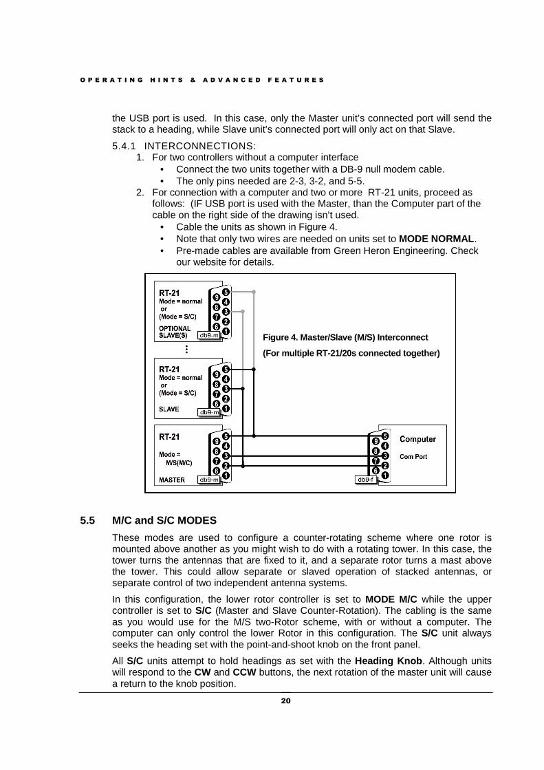
the USB port is used. In this case, only the Master unit’s connected port will send the stack to a heading, while Slave unit’s connected port will only act on that Slave.
5.4.1 INTERCONNECTIONS: 1. For two controllers without a computer interface
• Connect the two units together with a DB-9 null modem cable. • The only pins needed are 2-3, 3-2, and 5-5.
2. For connection with a computer and two or more RT-21 units, proceed as follows: (IF USB port is used with the Master, than the Computer part of the cable on the right side of the drawing isn’t used.
• Cable the units as shown in Figure 4. • Note that only two wires are needed on units set to MODE NORMAL . • Pre-made cables are available from Green Heron Engineering. Check
our website for details.
Figure 4. Master/Slave (M/S) Interconnect
(For multiple RT-21/20s connected together)
5.5 M/C and S/C MODES
These modes are used to configure a counter-rotating scheme where one rotor is mounted above another as you might wish to do with a rotating tower. In this case, the tower turns the antennas that are fixed to it, and a separate rotor turns a mast above the tower. This could allow separate or slaved operation of stacked antennas, or separate control of two independent antenna systems.
In this configuration, the lower rotor controller is set to MODE M/C while the upper controller is set to S/C (Master and Slave Counter-Rotation). The cabling is the same as you would use for the M/S two-Rotor scheme, with or without a computer. The computer can only control the lower Rotor in this configuration. The S/C unit always seeks the heading set with the point-and-shoot knob on the front panel.
All S/C units attempt to hold headings as set with the Heading Knob . Although units will respond to the CW and CCW buttons, the next rotation of the master unit will cause a return to the knob position.
O P E R A T I N G H I N T S & A D V A N C E D F E A T U R E S
21
The lower unit will turn as commanded, either manually, point-and-shoot, or by software command, and the upper unit will compensate and hold the desired, indicated heading by turning in the opposite direction. When beyond an endpoint (soft limits), the upper unit “flops over” and turns 360 degrees in the other direction.
It is important to calibrate the slave units after the master one. Set the master one to the center-of-rotation (normally North or South) and then calibrate the slaves to the same heading.
There is an internal setting that allows you to customize the time delay between Counter-Rotation commands sent from the Master. This will act to slow down or speed up the reaction of the slave to the master and reduce or increase the number of slave turn commands that occur for any motion from the Master. The default value for this is 10 seconds, contact the factory if you need to adjust this value.
Use M/C for your main rotating tower base or rotating joint. Use S/C for the upper rotor (above the tower) and/or Ring Rotor or sidearm installations above the rotating joint. The master unit may be turned by any allowable method (manual, preset, computer). The slave units will track their current heading as set with the heading knob. S/C headings may be changed using the heading knob only. A slave unit counter-rotates beyond the soft limit, the unit “flops over” and turns 360 degrees in the other direction.
5.6 DEBUG Mode
5.6.1 This mode enables troubleshooting of the system by allowing continuous rotation regardless of detected errors:
1. It enables continuous updating of position data on the display. 2. It disables the NO MOTION, POT RANGE, and (v3) COUNTER RANGE
ERRORS from resetting the controller so that you may determine the cause of these errors. Naturally, with MODE = DEBUG, caution to prevent ov er-rotation should be exercised if your system has no mechanical limit switches.
5.7 FIRMWARE UPDATES (see page iii for RT-21 v3 in formation)
Firmware updates, should one ever be desired or needed, are easy and fast to field install. The process requires only a straight through serial cable (the same one you may be using for computer control), the loader program (tinybldWin.exe), and the program file (RT-21 n_nn.hex) that you wish to load. The firmware and loader are available on our website under Technical Support. Updates cannot be done using the USB port on the RT-21.
To use the loader:
1. Place the tinybldWIN.exe and the firmware file (.hex) in a folder and go to that folder.
2. Double click the program and “Browse” and select the hex file you want to load. Set the Comm window to 57600 and the COM port you are going to use.
3. With the RT-21 switched ON, connect the serial cable. Click on Write Flash and then quickly turn the controller OFF and then back ON before the loader times out.
O P E R A T I N G H I N T S & A D V A N C E D F E A T U R E S
22
NOTE: v3 RT-21 units download easier if you first turn the controller off, then click on Write Flash, then turn the controller ON before the loader times out..
The loading process should take just a few seconds. Stored SETUP values are not changed so your calibration should remain intact. If the new load adds new SETUP values or features, you may need to go and set these new values before using your RT-21 with the new software. Green Heron will provide these instructions if needed.
5.8 CHANGING THE VANITY DISPLAY, MOTION TIMEOUT, SE CURITY LOCK
There are some SETUP items that are not accessible from the front panel SETUP menus. These items are designed to add security or items that should not normally need to be accessed except on rare occasion. To access or change these items, use SETUP UTILITY (Appendix G).
5.9 ALTERNATE OFFSETS (Firmware 1.6 and later)
Allows user to set two alternate beam OFFSET values and to then quickly and easily toggle heading displays to them sequentially by tapping the CANCEL button. This is useful for stacking antennas on the same mast that have different orientations, or pattern directions. Eliminates the need to mentally add or subtract headings for different antennas that are mounted 90 or 180 degrees off of the main antenna, or for use with a rotary dipole or other antenna that is bi-directional. You use SETUP UTILITY to set one or two alternate OFFSET values and MODE=OFFSET in order to enable the feature. The status display indicates MAN, OF1 or OF2 to show selected OFFSET.
5.10 ADVANCED OPTIONS (Firmware 1.6 and later)
These Advanced Options are only accessible via the SETUP Utility software’s Advanced Options Tab.
5.10.1 Un-Freeze Display – This option allows the display to always track the Heading feedback at a slow rate as opposed to freezing the display to prevent digit rolling.
5.10.2 Fast Brake Release – This option ignores the DELAY setting for the Brake Release feature to allow the use of the Brake Relay for Contact Closure applications. For RT-21r units, this changes the behavior of the switched +24V terminal 6 as well.
5.10.3 Auto Go-Back – Allows automatic compensating for long ramp downs when using manual CW and CCW Buttons. After releasing a button, if you tap it again while the rotor is ramping down, the unit will reverse after the stop, and go back to the heading at the time of the initial button release. An extra arrow indicator will show you that it will reverse after the delay.
5.10.4 Elevation Mode – This option will change the display to show negative numbers for below the horizon when controlling an elevation rotator. Headings between 261.1 and 359.9 will display as –99.9 through –00.1.
O P E R A T I N G H I N T S & A D V A N C E D F E A T U R E S
23
5.10.5 Analog Out – The controller will provide a 0 ~4 VDC output on pin 9 of the DB-9 RS-232 connector for PCB versions 2.2 and later. The voltage will track the HEADING value in a linear fashion, intended to drive the VBI-360 LED display. Earlier units may be modified to gain access to this output. Pin 6 (DTR) is pulled up through a 10k resistor whenever the controller is on.
5.10.6 EME Mode – This option disables the pulse counter after the motor has stopped after the DELAYS time. Intended to eliminate extra counts on very large EME arrays that are caused by the sensor rocking back and forth in the wind. This is only possible for large arrays that move very slowly so that the sensor always stops near the switch, and the array is large enough that the wind can move back through the gears and wiggle the motor shaft.
5.10.7 Point & Shoot Shortest Route – This option extends the Shortest Route logic to the Point-and-Shoot knob. Shortest Route turns the rotator the shortest way to get to a heading for rotators that allow rotation more than 360 degrees. This will not work properly if your Soft Limits are not set correctly. Shortest Route is always enabled for computer generated commands.
5.10.8 Port 9600 – Sets the baud rate on the EIA-232 DB-9 port to 9600 baud. 4800 Baud is the DCU-1 standard but some programs allow this to be run faster.
A P P E N D I X A
24
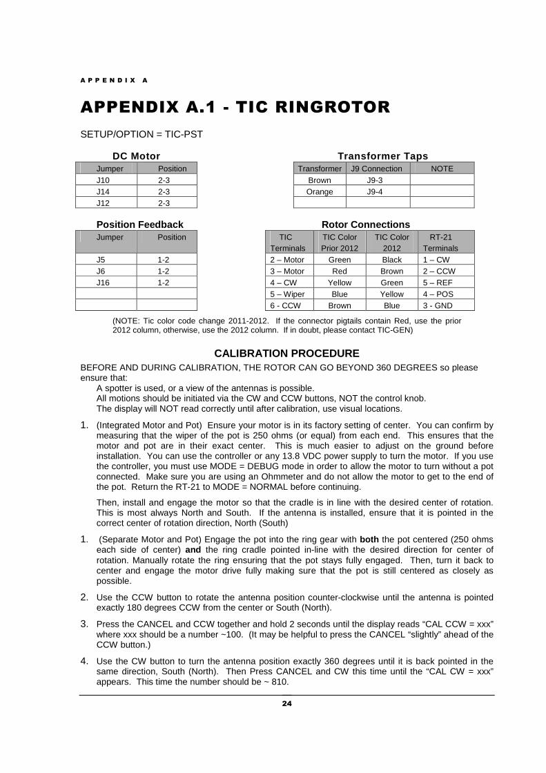
APPENDIX A.1 - TIC RINGROTOR
SETUP/OPTION = TIC-PST
DC Motor Transformer Taps Jumper Position Transformer J9 Connection NOTE J10 2-3 Brown J9-3 J14 2-3 Orange J9-4 J12 2-3
Position Feedback Rotor Connections Jumper Position TIC
Terminals TIC Color Prior 2012
TIC Color 2012
RT-21 Terminals
J5 1-2 2 – Motor Green Black 1 – CW J6 1-2 3 – Motor Red Brown 2 – CCW J16 1-2 4 – CW Yellow Green 5 – REF 5 – Wiper Blue Yellow 4 – POS 6 - CCW Brown Blue 3 - GND
(NOTE: Tic color code change 2011-2012. If the connector pigtails contain Red, use the prior 2012 column, otherwise, use the 2012 column. If in doubt, please contact TIC-GEN)
CALIBRATION PROCEDURE BEFORE AND DURING CALIBRATION, THE ROTOR CAN GO BEYOND 360 DEGREES so please ensure that: A spotter is used, or a view of the antennas is possible. All motions should be initiated via the CW and CCW buttons, NOT the control knob. The display will NOT read correctly until after calibration, use visual locations.
1. (Integrated Motor and Pot) Ensure your motor is in its factory setting of center. You can confirm by measuring that the wiper of the pot is 250 ohms (or equal) from each end. This ensures that the motor and pot are in their exact center. This is much easier to adjust on the ground before installation. You can use the controller or any 13.8 VDC power supply to turn the motor. If you use the controller, you must use MODE = DEBUG mode in order to allow the motor to turn without a pot connected. Make sure you are using an Ohmmeter and do not allow the motor to get to the end of the pot. Return the RT-21 to MODE = NORMAL before continuing.
Then, install and engage the motor so that the cradle is in line with the desired center of rotation. This is most always North and South. If the antenna is installed, ensure that it is pointed in the correct center of rotation direction, North (South)
1. (Separate Motor and Pot) Engage the pot into the ring gear with both the pot centered (250 ohms each side of center) and the ring cradle pointed in-line with the desired direction for center of rotation. Manually rotate the ring ensuring that the pot stays fully engaged. Then, turn it back to center and engage the motor drive fully making sure that the pot is still centered as closely as possible.
2. Use the CCW button to rotate the antenna position counter-clockwise until the antenna is pointed exactly 180 degrees CCW from the center or South (North).
3. Press the CANCEL and CCW together and hold 2 seconds until the display reads “CAL CCW = xxx” where xxx should be a number ~100. (It may be helpful to press the CANCEL “slightly” ahead of the CCW button.)
4. Use the CW button to turn the antenna position exactly 360 degrees until it is back pointed in the same direction, South (North). Then Press CANCEL and CW this time until the “CAL CW = xxx” appears. This time the number should be ~ 810.
A P P E N D I X A
25
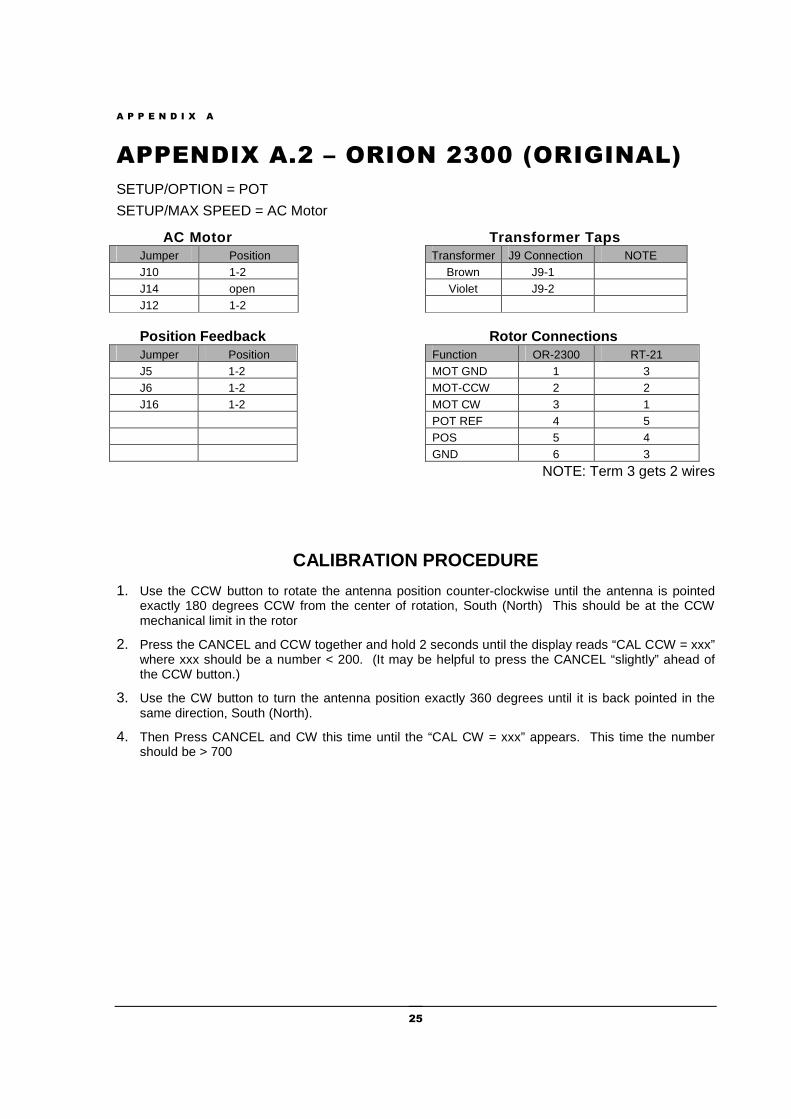
APPENDIX A.2 – ORION 2300 (ORIGINAL)
SETUP/OPTION = POT
SETUP/MAX SPEED = AC Motor
AC Motor Transformer Taps Jumper Position Transformer J9 Connection NOTE J10 1-2 Brown J9-1 J14 open Violet J9-2 J12 1-2
Position Feedback Rotor Connections Jumper Position Function OR-2300 RT-21 J5 1-2 MOT GND 1 3 J6 1-2 MOT-CCW 2 2 J16 1-2 MOT CW 3 1 POT REF 4 5 POS 5 4 GND 6 3
NOTE: Term 3 gets 2 wires
CALIBRATION PROCEDURE
1. Use the CCW button to rotate the antenna position counter-clockwise until the antenna is pointed exactly 180 degrees CCW from the center of rotation, South (North) This should be at the CCW mechanical limit in the rotor
2. Press the CANCEL and CCW together and hold 2 seconds until the display reads “CAL CCW = xxx” where xxx should be a number < 200. (It may be helpful to press the CANCEL “slightly” ahead of the CCW button.)
3. Use the CW button to turn the antenna position exactly 360 degrees until it is back pointed in the same direction, South (North).
4. Then Press CANCEL and CW this time until the “CAL CW = xxx” appears. This time the number should be > 700
A P P E N D I X A
26
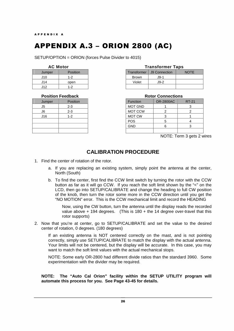
APPENDIX A.3 – ORION 2800 (AC)
SETUP/OPTION = ORION (forces Pulse Divider to 4015)
AC Motor Transformer Taps Jumper Position Transformer J9 Connection NOTE J10 1-2 Brown J9-1 J14 open Violet J9-2 J12 1-2
Position Feedback Rotor Connections Jumper Position Function OR-2800AC RT-21 J5 2-3 MOT GND 1 3 J6 2-3 MOT CCW 2 2 J16 1-2 MOT CW 3 1 POS 5 4 GND 6 3
NOTE: Term 3 gets 2 wires
CALIBRATION PROCEDURE
1. Find the center of rotation of the rotor.
a. If you are replacing an existing system, simply point the antenna at the center, North (South)
b. To find the center, first find the CCW limit switch by turning the rotor with the CCW button as far as it will go CCW. If you reach the soft limit shown by the “<” on the LCD, then go into SETUP/CALIBRATE and change the heading to full CW position of the knob, then turn the rotor some more in the CCW direction until you get the “NO MOTION” error. This is the CCW mechanical limit and record the HEADING
Now, using the CW button, turn the antenna until the display reads the recorded value above + 194 degrees. (This is 180 + the 14 degree over-travel that this rotor supports)
2. Now that you’re at center, go to SETUP/CALIBRATE and set the value to the desired center of rotation, 0 degrees. (180 degrees)
If an existing antenna is NOT centered correctly on the mast, and is not pointing correctly, simply use SETUP/CALIBRATE to match the display with the actual antenna. Your limits will not be centered, but the display will be accurate. In this case, you may want to match the soft limit values with the actual mechanical stops.
NOTE: Some early OR-2800 had different divide ratios than the standard 3960. Some experimentation with the divider may be required.
NOTE: The “Auto Cal Orion” facility within the SET UP UTILITY program will automate this process for you. See Page 43-45 for details.
A P P E N D I X A
27
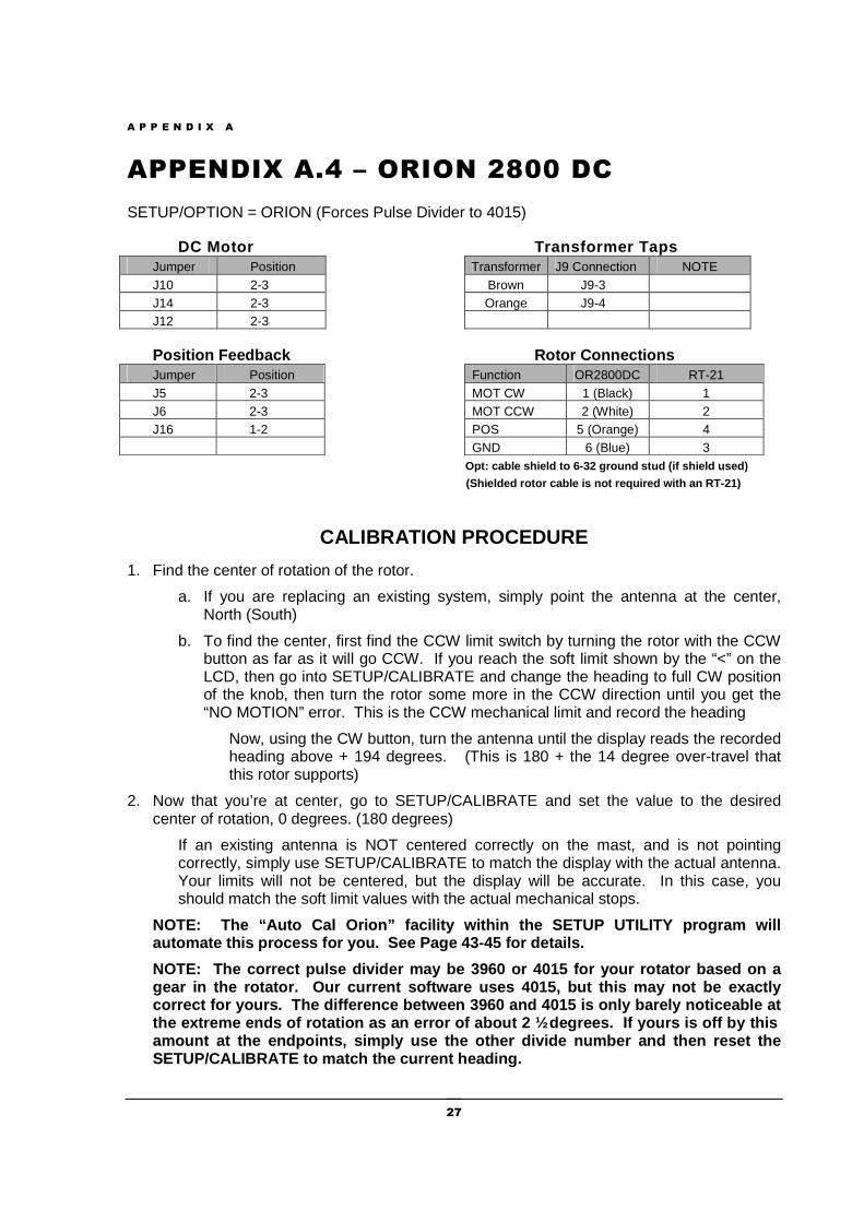
APPENDIX A.4 – ORION 2800 DC
SETUP/OPTION = ORION (Forces Pulse Divider to 4015)
DC Motor Transformer Taps Jumper Position Transformer J9 Connection NOTE J10 2-3 Brown J9-3 J14 2-3 Orange J9-4 J12 2-3
Position Feedback Rotor Connections Jumper Position Function OR2800DC RT-21 J5 2-3 MOT CW 1 (Black) 1 J6 2-3 MOT CCW 2 (White) 2 J16 1-2 POS 5 (Orange) 4 GND 6 (Blue) 3
Opt: cable shield to 6-32 ground stud (if shield used)
(Shielded rotor cable is not required with a n RT-21)
CALIBRATION PROCEDURE
1. Find the center of rotation of the rotor.
a. If you are replacing an existing system, simply point the antenna at the center, North (South)
b. To find the center, first find the CCW limit switch by turning the rotor with the CCW button as far as it will go CCW. If you reach the soft limit shown by the “<” on the LCD, then go into SETUP/CALIBRATE and change the heading to full CW position of the knob, then turn the rotor some more in the CCW direction until you get the “NO MOTION” error. This is the CCW mechanical limit and record the heading
Now, using the CW button, turn the antenna until the display reads the recorded heading above + 194 degrees. (This is 180 + the 14 degree over-travel that this rotor supports)
2. Now that you’re at center, go to SETUP/CALIBRATE and set the value to the desired center of rotation, 0 degrees. (180 degrees)
If an existing antenna is NOT centered correctly on the mast, and is not pointing correctly, simply use SETUP/CALIBRATE to match the display with the actual antenna. Your limits will not be centered, but the display will be accurate. In this case, you should match the soft limit values with the actual mechanical stops.
NOTE: The “Auto Cal Orion” facility within the SET UP UTILITY program will automate this process for you. See Page 43-45 for details.
NOTE: The correct pulse divider may be 3960 or 401 5 for your rotator based on a gear in the rotator. Our current software uses 401 5, but this may not be exactly correct for yours. The difference between 3960 and 4015 is only barely noticeable at the extreme ends of rotation as an error of about 2 ½ degrees. If yours is off by this amount at the endpoints, simply use the other divid e number and then reset the SETUP/CALIBRATE to match the current heading.
A P P E N D I X A
28
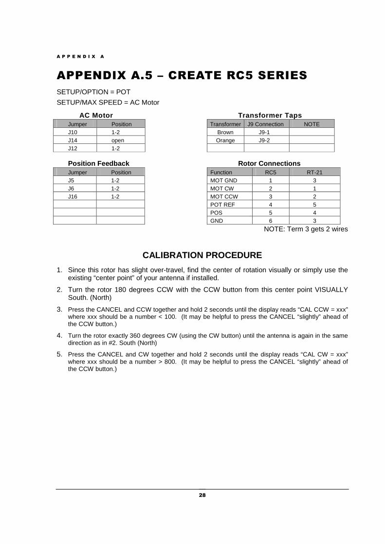
APPENDIX A.5 – CREATE RC5 SERIES
SETUP/OPTION = POT
SETUP/MAX SPEED = AC Motor
AC Motor Transformer Taps Jumper Position Transformer J9 Connection NOTE J10 1-2 Brown J9-1 J14 open Orange J9-2 J12 1-2
Position Feedback Rotor Connections Jumper Position Function RC5 RT-21 J5 1-2 MOT GND 1 3 J6 1-2 MOT CW 2 1 J16 1-2 MOT CCW 3 2 POT REF 4 5 POS 5 4 GND 6 3
NOTE: Term 3 gets 2 wires
CALIBRATION PROCEDURE
1. Since this rotor has slight over-travel, find the center of rotation visually or simply use the existing “center point” of your antenna if installed.
2. Turn the rotor 180 degrees CCW with the CCW button from this center point VISUALLY South. (North)
3. Press the CANCEL and CCW together and hold 2 seconds until the display reads “CAL CCW = xxx” where xxx should be a number < 100. (It may be helpful to press the CANCEL “slightly” ahead of the CCW button.)
4. Turn the rotor exactly 360 degrees CW (using the CW button) until the antenna is again in the same direction as in #2. South (North)
5. Press the CANCEL and CW together and hold 2 seconds until the display reads “CAL CW = xxx” where xxx should be a number > 800. (It may be helpful to press the CANCEL “slightly” ahead of the CCW button.)
A P P E N D I X A
29
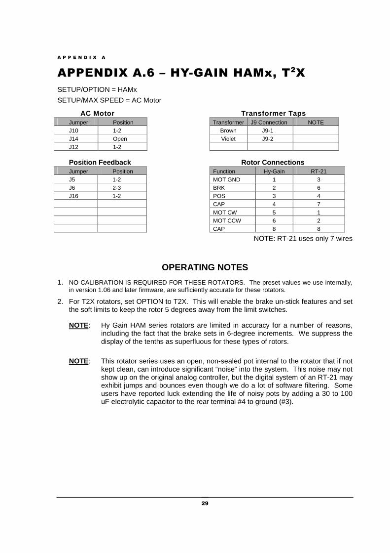
APPENDIX A.6 – HY-GAIN HAMx, T2X
SETUP/OPTION = HAMx
SETUP/MAX SPEED = AC Motor
AC Motor Transformer Taps Jumper Position Transformer J9 Connection NOTE J10 1-2 Brown J9-1 J14 Open Violet J9-2 J12 1-2
Position Feedback Rotor Connections Jumper Position Function Hy-Gain RT-21 J5 1-2 MOT GND 1 3 J6 2-3 BRK 2 6 J16 1-2 POS 3 4 CAP 4 7 MOT CW 5 1 MOT CCW 6 2 CAP 8 8
NOTE: RT-21 uses only 7 wires
OPERATING NOTES
1. NO CALIBRATION IS REQUIRED FOR THESE ROTATORS. The preset values we use internally, in version 1.06 and later firmware, are sufficiently accurate for these rotators.
2. For T2X rotators, set OPTION to T2X. This will enable the brake un-stick features and set the soft limits to keep the rotor 5 degrees away from the limit switches.
NOTE: Hy Gain HAM series rotators are limited in accuracy for a number of reasons, including the fact that the brake sets in 6-degree increments. We suppress the display of the tenths as superfluous for these types of rotors.
NOTE: This rotator series uses an open, non-sealed pot internal to the rotator that if not kept clean, can introduce significant “noise” into the system. This noise may not show up on the original analog controller, but the digital system of an RT-21 may exhibit jumps and bounces even though we do a lot of software filtering. Some users have reported luck extending the life of noisy pots by adding a 30 to 100 uF electrolytic capacitor to the rear terminal #4 to ground (#3).
A P P E N D I X A
30
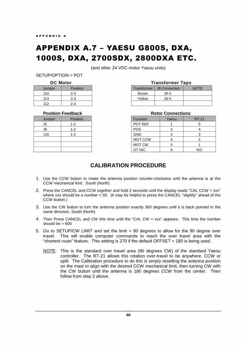
APPENDIX A.7 – YAESU G800S, DXA,
1000S, DXA, 2700SDX, 2800DXA ETC.
(and other 24 VDC motor Yaesu units)
SETUP/OPTION = POT
DC Motor Transformer Taps Jumper Position Transformer J9 Connection NOTE J10 2-3 Brown J9-3 J14 2-3 Yellow J9-4 J12 2-3
Position Feedback Rotor Connections Jumper Position Function Yaesu RT-21 J5 1-2 POT REF 1 5 J6 1-2 POS 2 4 J16 1-2 GND 3 3 MOT CCW 4 2 MOT CW 5 1 OT N/C 6 N/C
CALIBRATION PROCEDURE
1. Use the CCW button to rotate the antenna position counter-clockwise until the antenna is at the CCW mechanical limit. South (North)
2. Press the CANCEL and CCW together and hold 2 seconds until the display reads “CAL CCW = xxx” where xxx should be a number < 50. (It may be helpful to press the CANCEL “slightly” ahead of the CCW button.)
3. Use the CW button to turn the antenna position exactly 360 degrees until it is back pointed in the same direction. South (North)
4. Then Press CANCEL and CW this time until the “CAL CW = xxx” appears. This time the number should be > 600
5. Go to SETUP/CW LIMIT and set the limit + 90 degrees to allow for the 90 degree over travel. This will enable computer commands to reach the over travel area with the “shortest route” feature. This setting is 270 if the default OFFSET = 180 is being used.
NOTE: This is the standard over travel area (90 degrees CW) of the standard Yaesu controller. The RT-21 allows this rotation over-travel to be anywhere, CCW or split. The Calibration procedure to do this is simply resetting the antenna position on the mast to align with the desired CCW mechanical limit, then turning CW with the CW button until the antenna is 180 degrees CCW from the center. Then follow from step 2 above.
A P P E N D I X A
31
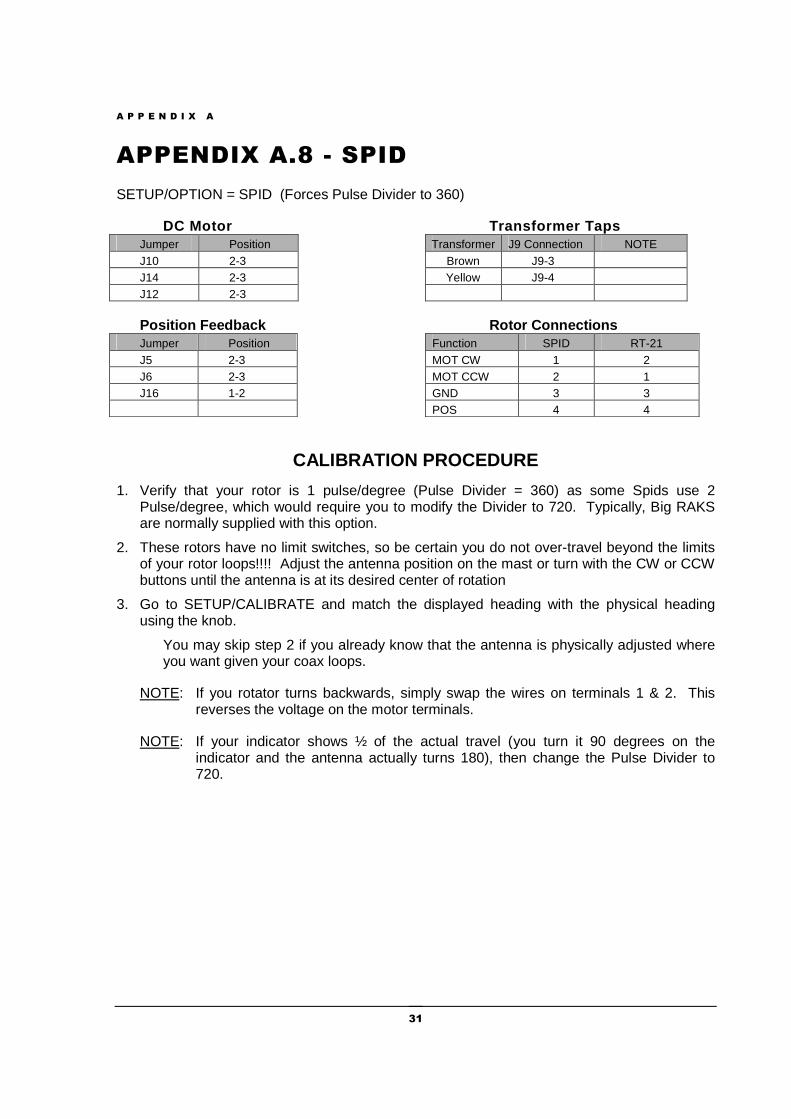
APPENDIX A.8 - SPID
SETUP/OPTION = SPID (Forces Pulse Divider to 360)
DC Motor Transformer Taps Jumper Position Transformer J9 Connection NOTE J10 2-3 Brown J9-3 J14 2-3 Yellow J9-4 J12 2-3
Position Feedback Rotor Connections Jumper Position Function SPID RT-21 J5 2-3 MOT CW 1 2 J6 2-3 MOT CCW 2 1 J16 1-2 GND 3 3 POS 4 4
CALIBRATION PROCEDURE
1. Verify that your rotor is 1 pulse/degree (Pulse Divider = 360) as some Spids use 2 Pulse/degree, which would require you to modify the Divider to 720. Typically, Big RAKS are normally supplied with this option.
2. These rotors have no limit switches, so be certain you do not over-travel beyond the limits of your rotor loops!!!! Adjust the antenna position on the mast or turn with the CW or CCW buttons until the antenna is at its desired center of rotation
3. Go to SETUP/CALIBRATE and match the displayed heading with the physical heading using the knob.
You may skip step 2 if you already know that the antenna is physically adjusted where you want given your coax loops.
NOTE: If you rotator turns backwards, simply swap the wires on terminals 1 & 2. This reverses the voltage on the motor terminals.
NOTE: If your indicator shows ½ of the actual travel (you turn it 90 degrees on the indicator and the antenna actually turns 180), then change the Pulse Divider to 720.
A P P E N D I X A
32
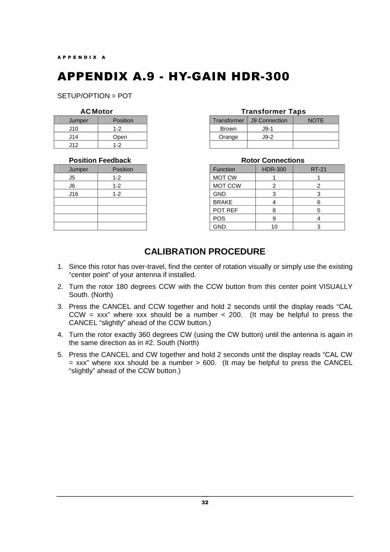
APPENDIX A.9 - HY-GAIN HDR-300
SETUP/OPTION = POT
AC Motor Transformer Taps Jumper Position Transformer J9 Connection NOTE J10 1-2 Brown J9-1 J14 Open Orange J9-2 J12 1-2
Position Feedback Rotor Connections Jumper Position Function HDR-300 RT-21 J5 1-2 MOT CW 1 1 J6 1-2 MOT CCW 2 2 J16 1-2 GND 3 3 BRAKE 4 6 POT REF 8 5 POS 9 4 GND 10 3
CALIBRATION PROCEDURE
1. Since this rotor has over-travel, find the center of rotation visually or simply use the existing “center point” of your antenna if installed.
2. Turn the rotor 180 degrees CCW with the CCW button from this center point VISUALLY South. (North)
3. Press the CANCEL and CCW together and hold 2 seconds until the display reads “CAL CCW = xxx” where xxx should be a number < 200. (It may be helpful to press the CANCEL “slightly” ahead of the CCW button.)
4. Turn the rotor exactly 360 degrees CW (using the CW button) until the antenna is again in the same direction as in #2. South (North)
5. Press the CANCEL and CW together and hold 2 seconds until the display reads “CAL CW = xxx” where xxx should be a number > 600. (It may be helpful to press the CANCEL “slightly” ahead of the CCW button.)
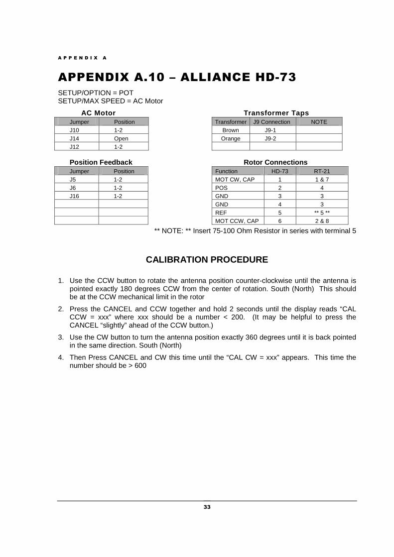
A P P E N D I X A
33
APPENDIX A.10 – ALLIANCE HD-73
SETUP/OPTION = POT SETUP/MAX SPEED = AC Motor
AC Motor Transformer Taps Jumper Position Transformer J9 Connection NOTE J10 1-2 Brown J9-1 J14 Open Orange J9-2 J12 1-2
Position Feedback Rotor Connections Jumper Position Function HD-73 RT-21 J5 1-2 MOT CW, CAP 1 1 & 7 J6 1-2 POS 2 4 J16 1-2 GND 3 3 GND 4 3 REF 5 ** 5 ** MOT CCW, CAP 6 2 & 8
** NOTE: ** Insert 75-100 Ohm Resistor in series with terminal 5
CALIBRATION PROCEDURE
1. Use the CCW button to rotate the antenna position counter-clockwise until the antenna is pointed exactly 180 degrees CCW from the center of rotation. South (North) This should be at the CCW mechanical limit in the rotor
2. Press the CANCEL and CCW together and hold 2 seconds until the display reads “CAL CCW = xxx” where xxx should be a number < 200. (It may be helpful to press the CANCEL “slightly” ahead of the CCW button.)
3. Use the CW button to turn the antenna position exactly 360 degrees until it is back pointed in the same direction. South (North)
4. Then Press CANCEL and CW this time until the “CAL CW = xxx” appears. This time the number should be > 600
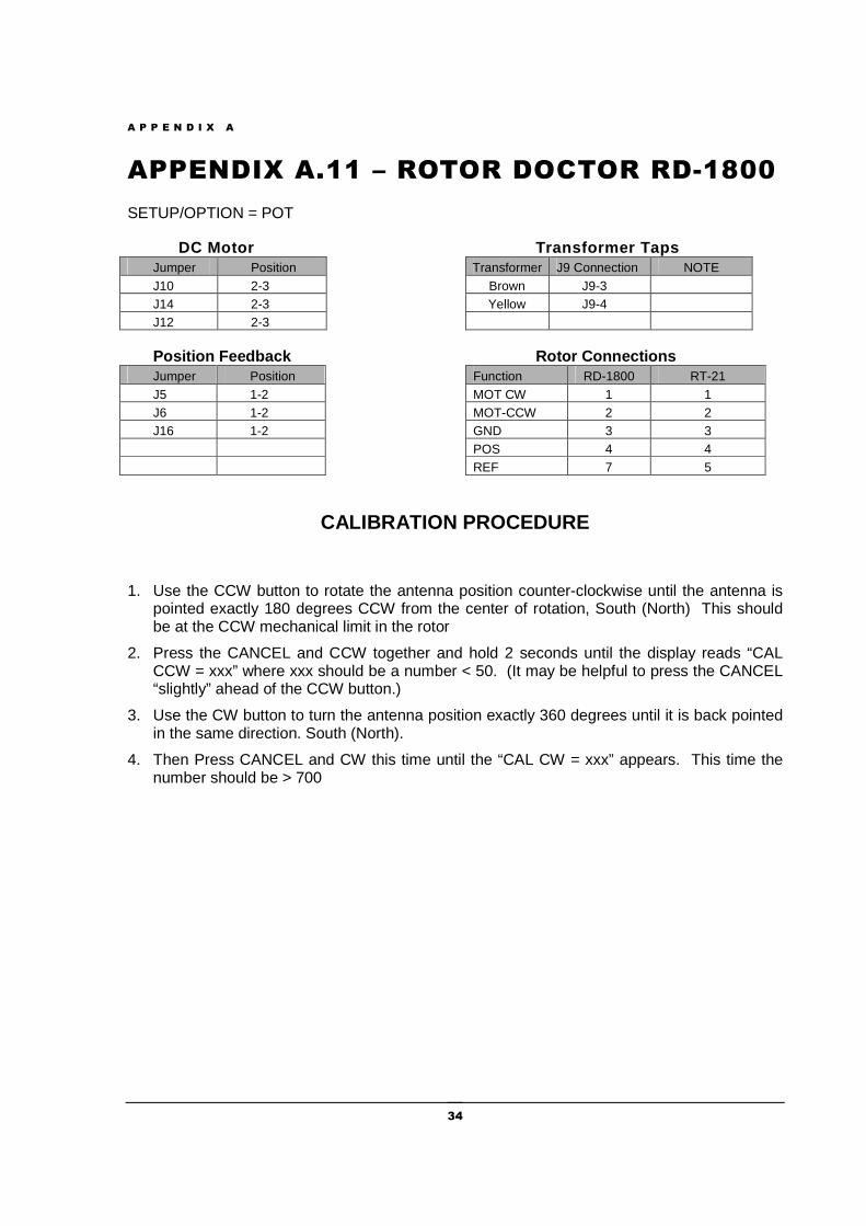
A P P E N D I X A
34
APPENDIX A.11 – ROTOR DOCTOR RD-1800
SETUP/OPTION = POT
DC Motor Transformer Taps Jumper Position Transformer J9 Connection NOTE J10 2-3 Brown J9-3 J14 2-3 Yellow J9-4 J12 2-3
Position Feedback Rotor Connections Jumper Position Function RD-1800 RT-21 J5 1-2 MOT CW 1 1 J6 1-2 MOT-CCW 2 2 J16 1-2 GND 3 3 POS 4 4 REF 7 5
CALIBRATION PROCEDURE
1. Use the CCW button to rotate the antenna position counter-clockwise until the antenna is pointed exactly 180 degrees CCW from the center of rotation, South (North) This should be at the CCW mechanical limit in the rotor
2. Press the CANCEL and CCW together and hold 2 seconds until the display reads “CAL CCW = xxx” where xxx should be a number < 50. (It may be helpful to press the CANCEL “slightly” ahead of the CCW button.)
3. Use the CW button to turn the antenna position exactly 360 degrees until it is back pointed in the same direction. South (North).
4. Then Press CANCEL and CW this time until the “CAL CW = xxx” appears. This time the number should be > 700
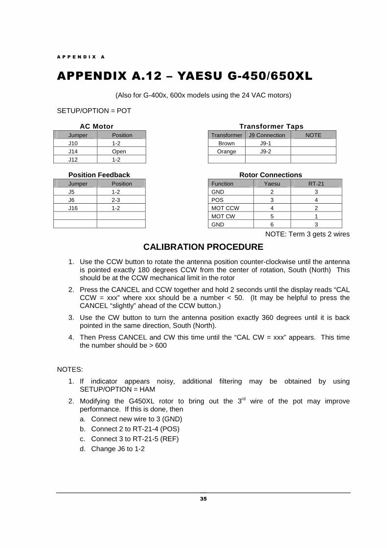
A P P E N D I X A
35
APPENDIX A.12 – YAESU G-450/650XL
(Also for G-400x, 600x models using the 24 VAC motors)
SETUP/OPTION = POT
AC Motor Transformer Taps Jumper Position Transformer J9 Connection NOTE J10 1-2 Brown J9-1 J14 Open Orange J9-2 J12 1-2
Position Feedback Rotor Connections Jumper Position Function Yaesu RT-21 J5 1-2 GND 2 3 J6 2-3 POS 3 4 J16 1-2 MOT CCW 4 2 MOT CW 5 1 GND 6 3
NOTE: Term 3 gets 2 wires
CALIBRATION PROCEDURE
1. Use the CCW button to rotate the antenna position counter-clockwise until the antenna is pointed exactly 180 degrees CCW from the center of rotation, South (North) This should be at the CCW mechanical limit in the rotor
2. Press the CANCEL and CCW together and hold 2 seconds until the display reads “CAL CCW = xxx” where xxx should be a number < 50. (It may be helpful to press the CANCEL “slightly” ahead of the CCW button.)
3. Use the CW button to turn the antenna position exactly 360 degrees until it is back pointed in the same direction, South (North).
4. Then Press CANCEL and CW this time until the “CAL CW = xxx” appears. This time the number should be > 600
NOTES:
1. If indicator appears noisy, additional filtering may be obtained by using SETUP/OPTION = HAM
2. Modifying the G450XL rotor to bring out the 3rd wire of the pot may improve performance. If this is done, then a. Connect new wire to 3 (GND) b. Connect 2 to RT-21-4 (POS) c. Connect 3 to RT-21-5 (REF) d. Change J6 to 1-2
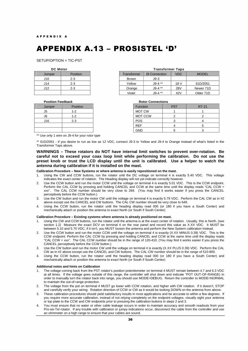
A P P E N D I X A
36
APPENDIX A.13 – PROSISTEL ‘D’
SETUP/OPTION = TIC-PST
DC Motor Transformer Taps
Jumper Position Transformer J9 Connection VDC MODEL J10 2-3 Brown J9-3
J14 2-3 Yellow J9-4 ** 18 V 61D/2051 J12 2-3 Orange J9-4 ** 28V Newer 71D
Violet J9-4 ** 42V Older 71D
Position Feedback Rotor Connections
Jumper Position Function PST RT-21
J5 1-2 MOT CW 1 1
J6 1-2 MOT CCW 2 2
J16 2-3 POS 3 4
REF 4 5
GND 5 3
** Use only 1 wire on J9-4 for your rotor type
** 61D/2051 - if you desire to run as low as 12 VDC, connect J9-3 to Yellow and J9-4 to Orange instead of what’s listed in the Transformer Taps above.
WARNINGS – These rotators do NOT have internal limi t switches to prevent over-rotation. Be careful not to exceed your coax loop limit while pe rforming the calibration. Do not use the preset knob or trust the LCD display until the unit is calibrated. Use a helper to watch the antenna during calibration if it is installed on th e mast. Calibration Procedure – New Systems or where antenn a is easily repositioned on the mast. 1. Using the CW and CCW buttons, run the rotator until the DC voltage on terminal 4 is exactly 5.40 VDC. This voltage
indicates the exact center of rotation. The Heading display will not yet indicate correctly however. 2. Use the CCW button and run the motor CCW until the voltage on terminal 4 is exactly 5.01 VDC. This is the CCW endpoint.
Perform the CAL CCW by pressing and holding CANCEL and CCW at the same time until the display reads “CAL CCW = xxx”. The CAL CCW number should be very close to 269. (You may find it works easier if you press the CANCEL perceptively before the CCW button.)
3. Use the CW button and run the motor CW until the voltage on terminal 4 is exactly 5.79 VDC. Perform the CAL CW as in #2 above except use the CANCEL and CW buttons. The CAL CW number should be very close to 649.
4. Using the CCW button, run the rotator until the heading display read 000 (or 180 if you have a South Center) and mechanically attach or position the antenna to exact North (or South if South Center)
Calibration Procedure – Existing systems where ante nna is already positioned on mast. 1. Using the CW and CCW buttons, run the rotator until the antenna is at the exact center of rotation. Usually, this is North. (see
section 1.2) Measure the exact DCV on terminal 4 on the rear panel and record this value as X.XX VDC. It MUST be between 5.10 and 5.70 VDC, if it isn’t, you MUST loosen the antenna and perform the New System calibration instead.
2. Use the CCW button and run the motor CCW until the voltage on terminal 4 is exactly (X.XX MINUS 0.39) VDC. This is the CCW endpoint. Perform the CAL CCW by pressing and holding CANCEL and CCW at the same time until the display reads “CAL CCW = xxx”. The CAL CCW number should be in the range of 120-410. (You may find it works easier if you press the CANCEL perceptively before the CCW button.)
3. Use the CW button and run the motor CW until the voltage on terminal 4 is exactly (X.XX PLUS 0.39) VDC. Perform the CAL CW as in #2 above except use the CANCEL and CW buttons. The CAL CW number should be in the range of 510-800.
4. Using the CCW button, run the rotator until the heading display read 000 (or 180 if you have a South Center) and mechanically attach or position the antenna to exact North (or South if South Center)
Additional notes and hints on Calibration 1. The voltage coming back from the PST rotator’s position potentiometer on terminal 4 MUST remain between 4.7 and 6.3 VDC
at all times. If the voltage goes outside of this range, the controller will shut down and indicate “POT OUT-OF-RANGE) In order to manually turn the rotator back into range, you should use MODE=DEBUG. Return the controller to MODE=NORMAL to maintain the out-of-range protection.
2. The voltage from the pot on terminal 4 MUST go lower with CCW rotation, and higher with CW rotation. If it doesn’t, STOP and carefully verify your wiring. Rotation direction of CCW or CW as it would be looking DOWN on the antenna from above.
3. These calibration procedures should yield satisfactory results in most applications and be accurate to within a few degrees. If you require more accurate calibration, instead of not relying completely on the endpoint voltages, visually sight your antenna or top plate to the CCW and CW endpoints prior to pressing the calibration buttons in steps 2 and 3.
4. You must ensure that no water or other cable leakage occurs in order to maintain accuracy and smooth readouts from your Pro-sis-Tel rotator. If any trouble with calibration or jumpy indications occur, disconnect the cable from the controller and use an ohmmeter on a high range to ensure that your cables are sound.
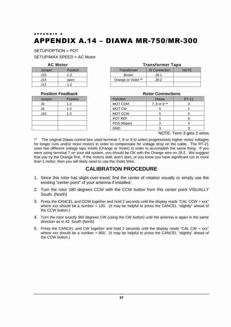
A P P E N D I X A
37
APPENDIX A.14 – DIAWA MR-750/MR-300
SETUP/OPTION = POT
SETUP/MAX SPEED = AC Motor
AC Motor Transformer Taps Jumper Position Transformer J9 Connection NOTE J10 1-2 Brown J9-1 J14 open Orange or Violet ** J9-2 J12 1-2
Position Feedback Rotor Connections Jumper Position Function Diawa RT-21 J5 1-2 MOT COM 7, 8 or 9 ** 3 J6 1-2 MOT CW 6 1 J16 1-2 MOT CCW 5 2 POT REF 1 5 POS (Wiper) 2 4 GND 3 3
NOTE: Term 3 gets 2 wires
** The original Diawa control box used terminal 7, 8 or 9 to select progressively higher motor voltages for longer runs and/or more motors in order to compensate for voltage drop on the cable. The RT-21 uses two different voltage taps inside (Orange or Violet) in order to accomplish the same thing. If you were using terminal 7 on your old system, you should be OK with the Orange wire on J9-2. We suggest that you try the Orange first. If the motors stall, won’t start, or you know you have significant run or more than 1 motor, then you will likely need to use the Violet Wire.
CALIBRATION PROCEDURE
1. Since this rotor has slight over-travel, find the center of rotation visually or simply use the existing “center point” of your antenna if installed.
2. Turn the rotor 180 degrees CCW with the CCW button from this center point VISUALLY South. (North)
3. Press the CANCEL and CCW together and hold 2 seconds until the display reads “CAL CCW = xxx” where xxx should be a number < 100. (It may be helpful to press the CANCEL “slightly” ahead of the CCW button.)
4. Turn the rotor exactly 360 degrees CW (using the CW button) until the antenna is again in the same direction as in #2. South (North)
5. Press the CANCEL and CW together and hold 2 seconds until the display reads “CAL CW = xxx” where xxx should be a number > 800. (It may be helpful to press the CANCEL “slightly” ahead of the CCW button.)
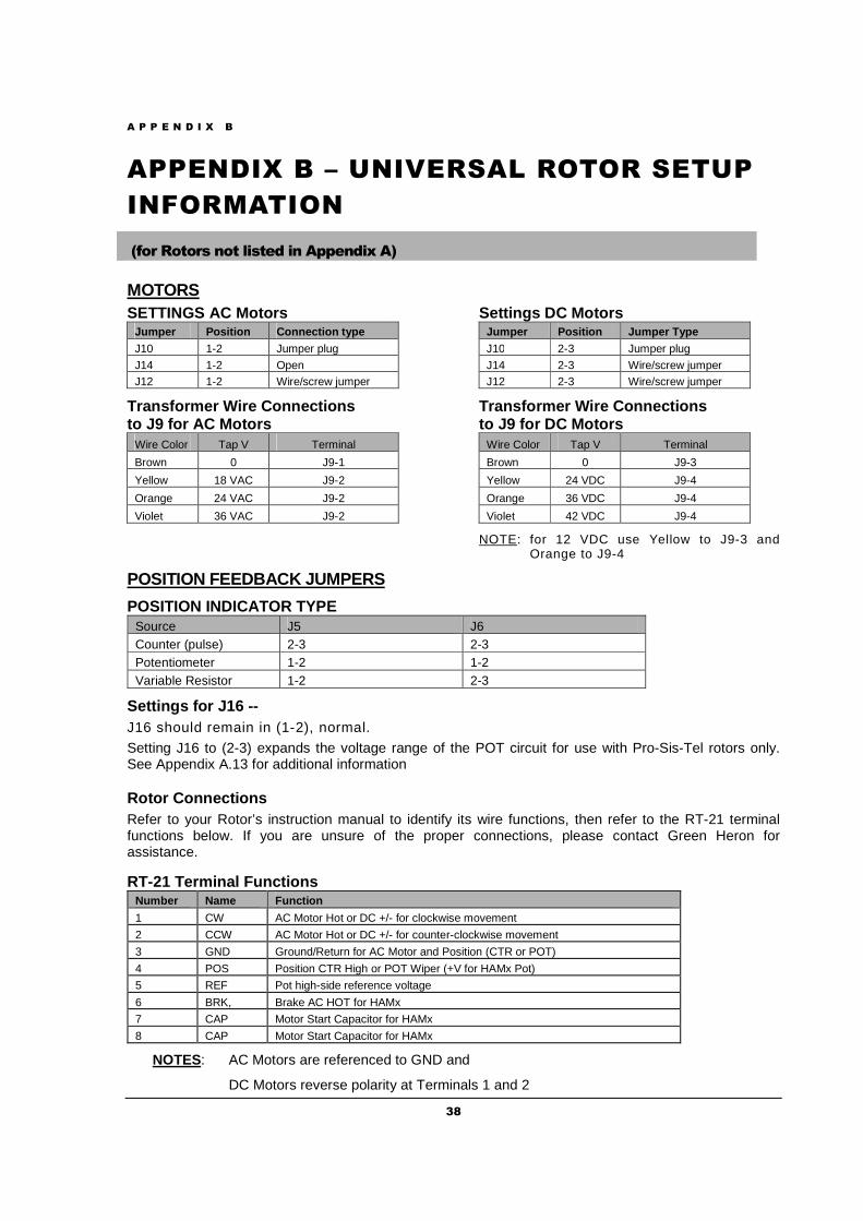
A P P E N D I X B
38
APPENDIX B – UNIVERSAL ROTOR SETUP
INFORMATION
(for Rotors not listed in Appendix A)
MOTORS SETTINGS AC Motors
Jumper Position Connection type J10 1-2 Jumper plug
J14 1-2 Open J12 1-2 Wire/screw jumper
Transformer Wire Connections to J9 for AC Motors
Wire Color Tap V Terminal
Brown 0 J9-1
Yellow 18 VAC J9-2
Orange 24 VAC J9-2
Violet 36 VAC J9-2
Settings DC Motors Jumper Position Jumper Type J10 2-3 Jumper plug
J14 2-3 Wire/screw jumper J12 2-3 Wire/screw jumper
Transformer Wire Connections to J9 for DC Motors
Wire Color Tap V Terminal
Brown 0 J9-3
Yellow 24 VDC J9-4
Orange 36 VDC J9-4
Violet 42 VDC J9-4
NOTE: for 12 VDC use Yellow to J9-3 and Orange to J9-4
POSITION FEEDBACK JUMPERS
POSITION INDICATOR TYPE Source J5 J6 Counter (pulse) 2-3 2-3 Potentiometer 1-2 1-2 Variable Resistor 1-2 2-3
Settings for J16 -- J16 should remain in (1-2), normal.
Setting J16 to (2-3) expands the voltage range of the POT circuit for use with Pro-Sis-Tel rotors only. See Appendix A.13 for additional information
Rotor Connections Refer to your Rotor’s instruction manual to identify its wire functions, then refer to the RT-21 terminal functions below. If you are unsure of the proper connections, please contact Green Heron for assistance.
RT-21 Terminal Functions Number Name Function
1 CW AC Motor Hot or DC +/- for clockwise movement
2 CCW AC Motor Hot or DC +/- for counter-clockwise movement
3 GND Ground/Return for AC Motor and Position (CTR or POT)
4 POS Position CTR High or POT Wiper (+V for HAMx Pot)
5 REF Pot high-side reference voltage
6 BRK, Brake AC HOT for HAMx
7 CAP Motor Start Capacitor for HAMx
8 CAP Motor Start Capacitor for HAMx
NOTES: AC Motors are referenced to GND and
DC Motors reverse polarity at Terminals 1 and 2
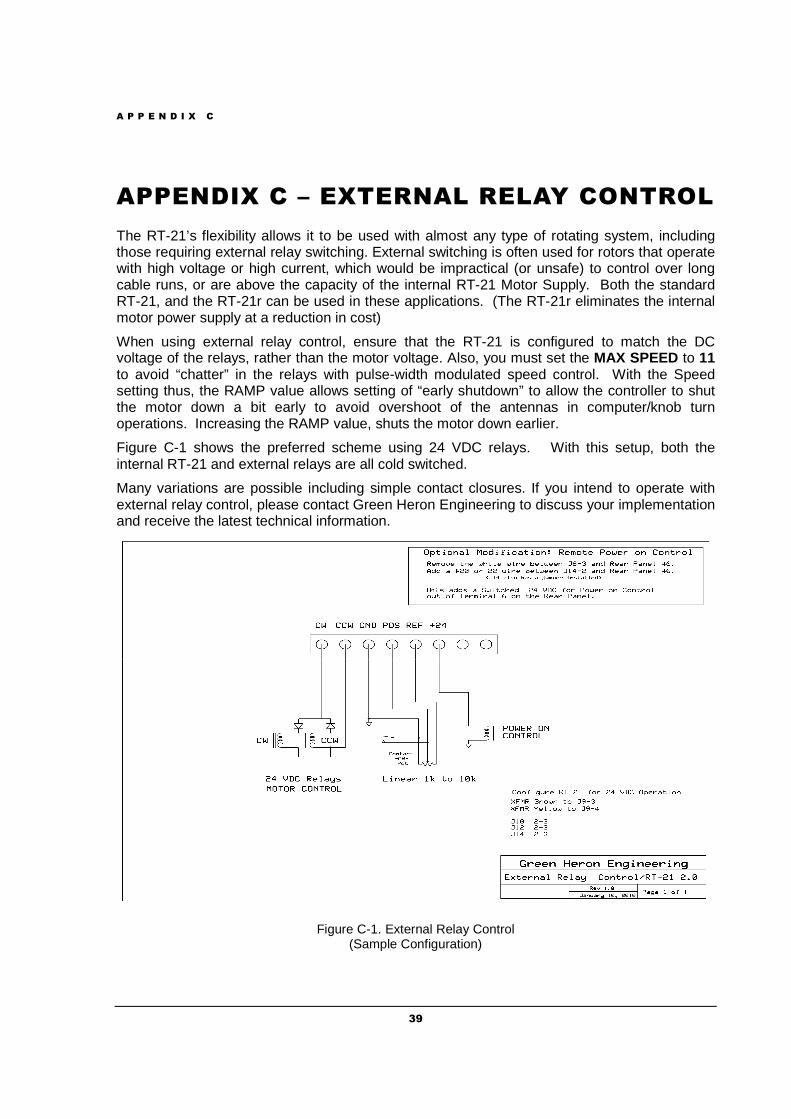
A P P E N D I X C
39
APPENDIX C – EXTERNAL RELAY CONTROL
The RT-21’s flexibility allows it to be used with almost any type of rotating system, including those requiring external relay switching. External switching is often used for rotors that operate with high voltage or high current, which would be impractical (or unsafe) to control over long cable runs, or are above the capacity of the internal RT-21 Motor Supply. Both the standard RT-21, and the RT-21r can be used in these applications. (The RT-21r eliminates the internal motor power supply at a reduction in cost)
When using external relay control, ensure that the RT-21 is configured to match the DC voltage of the relays, rather than the motor voltage. Also, you must set the MAX SPEED to 11 to avoid “chatter” in the relays with pulse-width modulated speed control. With the Speed setting thus, the RAMP value allows setting of “early shutdown” to allow the controller to shut the motor down a bit early to avoid overshoot of the antennas in computer/knob turn operations. Increasing the RAMP value, shuts the motor down earlier.
Figure C-1 shows the preferred scheme using 24 VDC relays. With this setup, both the internal RT-21 and external relays are all cold switched.
Many variations are possible including simple contact closures. If you intend to operate with external relay control, please contact Green Heron Engineering to discuss your implementation and receive the latest technical information.
Figure C-1. External Relay Control (Sample Configuration)
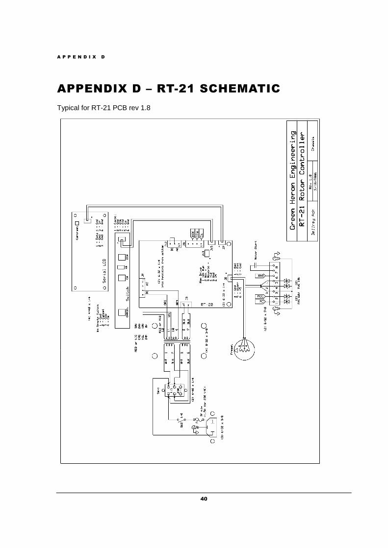
A P P E N D I X D
40
APPENDIX D – RT-21 SCHEMATIC
Typical for RT-21 PCB rev 1.8
A P P E N D I X E
41
APPENDIX E – ERROR MESSAGES ERROR NO MOTION
No Motion errors occur if your rotor attempts a rotation but does not detect a heading change of at least 2 degree in the allotted time, typically 2 or 4 seconds. This could indicate either that the rotor is not turning, OR, it is turning but the feedback mechanism is not working. In either event, the RT-21 stops the attempted motion to allow you to diagnose the problem without possibly damaging your coax or antennas. The Motor Timeout may be increased or decreased using SETUP Utility.
You will get No Motion error if you have your soft limits set outside (or beyond) your limit switches as the rotor attempts to keep turning. This, of course, is not a failure and you can prevent it by simply bringing the RT-21 soft limits to, or inside the limit switch positions.
TROUBLESHOOTING Rotor not turning: DC Motors – Disconnect wires from terminals 1 and 2, you should be able to read the rotor motor resistance (a few ohms) across the wires removed with an Ohmmeter. Consult your rotor documentation if you can’t. Be sure you aren’t up against a limit switch somehow. Check the RT-21 by setting, SPEED = 11 and, MODE = DEBUG. Push the CW or CCW buttons and read the motor voltage across the terminals 1 and 2. Voltage switches polarity with the other button.
AC Motors – Similar except separate wires CW or CCW read voltage to ground (3). Check your rotor and cable following the instructions in your manual. Rotor turning, no feedback : POT systems – Connect a 500 Ohm to 10k Ohm linear pot to terminals 3,4 and 5 with the wiper on 4. With the controller in DEBUG mode, you should be able to see the Heading display track the pot setting. You can even check the A/D endpoints by calibrating the controller to this pot at one end, then the other. You can read the position of the rotor’s pot back through the wires you removed.
HAM systems – similar except just hook up one end and the wiper of a 500 Ohm (must be this value) pot to terms 3 and 4. Check your Hy-Gain manual for specifics on testing your cable and rotor from the cable end with a meter.
COUNTER Systems – With MODE = DEBUG, use a clip lead to tap across terms 3 and 4. You should be able to see the display move CW or CCW depending on the last direction you attempted to rotate. If this works, you have a problem with you cabling or rotor sending switch.
ERROR POT OUT-OF-RANGE xxxx (OPTION = TIC-PST only)
This error indicates that the value being read by the A/D converter of the controller is below or above the normal operating range of the potentiometer in the rotor. The actual A/D value (xxxx) is displayed to let you know if it’s high or low. The controller will NOT function when this condition exists unless the controller is in MODE = DEBUG. A short circuit or open circuit in the pot wiring would cause this error. This error is independent of your calibration to yield the best protection. Correct Range: (Terminal 4 (POS) on rear panel)
TIC = 0.5 to 7.2 VDC (PCB Jumper J16 = 1-2) PST = 4.7 to 6.3 VDC (PCB Jumper J16 = 2-3)
COUNTER RANGE ERROR xxxx (New in 1.07/3.07) (OPTION = ORION, SPID, COUNTER only)
This error indicates that the value contained in the internal pulse counter is beyond the range allowed for your rotator as determined by the Pulse Divider setting. The controller allows +/- 90 degrees over-travel from 360 as default. The controller will remain inoperative until corrected by either a re-calibration, EE Reset, or turning it back into range by using MODE=DEBUG to ignore the error. Contact the factory if you desire to change the 90 degree OT Limit.
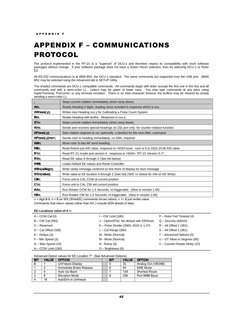
A P P E N D I X F
42
APPENDIX F – COMMUNICATIONS
PROTOCOL The protocol implemented in the RT-21 is a "superset" of DCU-1 and therefore retains its compatibility with most software packages without change. If your software package does not have a Green Heron selection, then try selecting DCU-1 or Rotor EZ.
All RS-232 communications is at 4800 8N1, the DCU-1 standard. The same commands are supported over the USB port. (9600 8N1 may be selected using the Advanced tab in SETUP Utility
The shaded commands are DCU-1 compatible commands. All commands begin with letter (except the first one in the list) and all commands end with a semi-colon (;). Letters may be upper or lower case. You may type commands at any pace using HyperTerminal, ProComm, or any terminal emulator. There is no inter-character timeout, the buffers may be cleared by simply sending a semi-colon (;).
���� Stops current rotation immediately (short ramp down)
���������������� Reads Heading 3 digits, leading zeros included in response which is xxx;
������������������������������������ Writes new Heading xxx.y for Calibrating a Pulse Count System
���������������� Reads Heading with tenths. Response is xxx.y;
��� ��� ��� ��� Stops current rotation immediately (short ramp down)
���������������� Sends and receives special headings on 232 port only for counter-rotation function.
������������������������������������ Sets rotation degrees to xxx optionally .y (tenths) for the next AMn; command
���������������������������������������������������� Sends rotor to heading immediately, no AMn; required
���������������� Move rotor to last AP send heading
���������������� Read Rotors pot A/D value, response is <SOH>xxxx; xxxx is 0 to 1023 10 bit A/D value
���������������� Read RT-21 model and version #. response is <SOH> "RT-21 Version X.Y";
���������������� Read EE value A through Z (See list below)
���������������� Loads Default EE values and Reset Controller
�������������������������������������������������������� Write vanity message centered on line three of display for boot message
������� !��������� !��������� !��������� !�� Write value to EE location A through Z (See list) (SEE n= below for info on EE Write)
"���"���"���"��� Force unit to CAL CCW at current position
"���"���"���"��� Force unit to CAL CW ant current position
���������������� Run Rotator CCW for 1.5 Seconds, re-triggerable. (New in version 1.06)
���������������� Run Rotator CW for 1.5 Seconds, re-triggerable. (New in version 1.06) � # $���% �&'( � # � )� �� ����%!**� �)++��$� ,)��!� �!-))%( � �� � . �% /��%!� ��� !
")++��$� %0�% �!% �� ��� !� �)%0!� %0�� ����� ���� $! 12 �0!�$ ), $�%�
EE Locations value of X =:
A – CCW Cal (0) I – CW Limit (180) P – Rotor Fail Timeout (4)
B – CW Cal (950) J – Option(Pot) No default with EEReset Q – Security (Admin)
C – Reserved K – Pulse Divider (3960, 4015 in 1.07) R – Alt Offset 1 (361)
D – Cal Offset (180) L – Cal Range (360) S – Alt Offset 2 (361)
E – Delays (3) M - Mode (Normal) T – Advanced Options (0)
F – Min Speed (3) M - Mode (Normal) U – OT Allow in Degrees (90)
G – Max Speed (10) N - Ramp (3) V – Counter-Rotate Delay (10)
H – CCW Limit (180) O – Brightness (8)
�$����!$ 13%�)� ��� !� ,)� ** 4)��%�)� 5�5 � !! �$����!$ 13%�)���
������������ ��46*��46*��46*��46* 1���171���171���171���17 ������������ ��46*��46*��46*��46* 1���171���171���171���17
� � 6�8�!!9! :��3�� ; <= ����)� 1 % ����<>��
� = �++!$��%! ���?! �!�!��! > >@ *�* �)$!
= @ � %) A)&���? B �=C 0)�%!�% �) %!
< C *�!��%�)� �)$! C =;> �)�% '>�� �� $
@ �> � %):�+ �� 6�,�!!9!
A P P E N D I X G
43
APPENDIX G – SETUP UTILITY
Introduction
SETUP UTILITY is a Java program and is distributed without the Java Runtime needed for operation. If your computer does not have the correct Java platform installed, you will be directed to the proper web location for download. SETUP is an easy to use utility that can be used with the Green Heron RT-21 controller to allow computer access to all of the SETUP items that can be done from the front panel SETUP menus. In addition, the SETUP UTILITY additionally provides for:
• Connecting to a controller via RS-232 or USB. • Rotor control and display of current heading. • Computer access to the front panel SETUP parameters. • Access to parameters that are hidden from the front panel.
o MOTOR TIMEOUT in seconds. o Security Setting to allow User lockout of SETUP and Resets. o Vanity Display changes for the LCD/VFD at start-up. o Direct setting of POT Calibration values
• Additional Calibration features for easy quick setup of new rotors o AUTO CAL for Orion o AUTO CAL for some POT style rotors
• Ability to Save and Recall calibration parameters for your specific rotor installations
Connecting
Select a COM port. Only ports that are really available are shown in the drop down Port box. Click To Connect – If a controller is on that COM port, Connected will be displayed in the Port section, and all of the various parameters will be read along with the Current Heading. NOTE: An older RT-20 can display and move to a new heading, but the rest of the window will remain grayed out as no functions, other than Rotor Control, work remotely on the RT-20. An upgrade kit, RT-20 to RT-21, is available that will yield full SETUP UTILITY functionality less the USB connection.
Rotor Control
The lower right corner of the window shows the Current Heading (yellow on black window) with a text box available to select a new heading. You can double click the New Heading box to type in a heading. Then click on Go. Stop will send the stop command to the rotor.
Computer Access to SETUP parameters
Rotor Type is the OPTION setting in front panel SETUP. Mode, Pulse Divisor, Motor Settings, Offset, Cal Range, Soft Limits and the Display Brightness all mimic the Front Panel SETUP parameters. If you have selected a Counter type of rotor, the Pulse Cal will be available too. See the manual for detailed descriptions of these settings. Some settings are with radio buttons. Some with sliders, and others require you to click on a Change button and type in a value.
Limits
The color bar in the Limits window gives you nice visual representation of the soft limits as read from the controller, or changed in the SETUP UTILITY. This bar takes into account both the OFFSET value and the Soft Limit values to graphically represent the rotational range. The center of the Limits window IS ALWAYS the center of rotation. This may not always be coincident with the center of the red bar if the limits are not equally set away from their centers.
A P P E N D I X G
44
Do CCW Cal & Do CW Cal These buttons mimic the front panel CANCEL + CCW and CANCEL + CW buttons that set the actual pot calibration A/D values into the controller. You must first have turned the rotor to the visual CCW and CW 360 degree endpoints by using the front panel buttons. Please refer to the manual for information on calibrating a POT system. Use the Read Settings and Write Settings buttons near the bottom of the Utility window, .to read and write from and to the controller. Reset button will mimic the CANCEL+CCW+CW buttons that cause a complete RESET EE function back to factory defaults.
Computer Access to “Hidden” parameters
Security If set to User, will disable access to SETUP, RESET EE and Pot Calibration from the front panel.
Motor Timeout Set this value higher than 2 seconds if your rotor is slow or you use very long ramping and may exceed the 2 seconds from time to time.
Set Vanity Will change the boot-up message on the display. You can enter up to 14 characters and they will be centered on the 3rd line of the display at start up. You must restart the controller after using this button. Close the SETUP UTILITY first if connected via USB.
Pot Cal You may also directly set the A/D values in the CW and CCW calibration locations without actually doing the pot calibration. If you know what the values are for your installation, you can put them back using this facility. You can also make small changes to the stored values, or set them full wide (0 and 960) prior to recalibrating. (as a substitute for doing a full Reset EE prior to calibration.) The A/D values (Analog to Digital Converter) is the voltage returned from the wiper of the indicator pot inside the rotor. It can range in value from 0 to around 960 which correspond to 0 VDC, to around 9.8 VDC.
Advanced Options Tab (Upper Left) Access to the Advanced Options is only allowed on controllers that read Firmware version 1.6 or later. These options are described in detail in Section 5.10 and are only turned on/off with the Advanced Options tab of SETUP UTILITY.
Auto Calibration
Pot Auto Cal Click this button to see the rotors that can be Preset Calibrated from standard values that will normally provide pretty close calibration. Different rotors can be added by editing the file RotorPresets.ini (located in the install directory). The values provided in this file are set into the A/D values that would normally be set using the normal calibration procedures. You can edit this file to put in different values
A P P E N D I X G
45
for different rotors of the same type. TIC 20, TIC 15 could be examples. You may calibrate each rotor normally, then you can edit the RotorPresets.ini to put the values in so they can be recalled at anytime from the Pot Auto Cal facility.
Auto Cal Orion Click this button to run the Orion Auto Calibration facility. This is quite different from the Pot Auto Cal that simply stuffs preset values into the controller memory. An Orion uses a pulse count system and has +/- 14 degrees of over-travel (360 + 28 degrees of rotation). It can sometimes be difficult to find the mechanical center of these rotors in order to set the direction of the antenna/mast in the rotor to the desired center. When you run the Auto Cal Orion, SETUP UTILITY will apply settings to the controller that allow bypassing of soft limits in order to find the mechanical CCW endstop limit switch. Then, it will turn the rotor back to the center by turning 180 plus 14 degrees and then setting the rotor calibrate to the desired center of rotation. SETUP knows that the center is always 180 degrees CW from the OFFSET value. When Auto Cal Orion is finished, the Orion rotor is run to the mechanical center of rotation and the Calibration value is set there too. You can then either mechanically turn the antenna on the mast to match your desired center, or if it’s close, simply reset the Calibrate Heading value to the actual antenna position. If you do change this value, the rotor will no longer be exactly centered. This will limit the amount of overtravel in one or the other direction, but the headings will be accurate.
Save and Recall Settings
You may save and recall complete sets of parameters that are stored in your controllers. This may be useful if you have multiple rotors and controllers and want backup settings in case you need to replace a controller, or accidentally erase settings. You may also use this facility to re-use one controller on different rotors in your stations(s) and quickly setup from one to another without having to reset a bunch of parameters and without having to perform the normal calibrations. After connecting to a controller that you wish to save, verify the settings and then press Save to File. In order to recall, do a Read from File . The currently connected controller will be restored automatically.

GREEN HERON ENGINEER ING LLC
2012 Green Heron Engineering LLC
1107 Salt Road, Webster, NY 14580 Phone 585.217.9093
www.GreenHeronEngineering.com


![[XLS]s446aec1b0de51350.jimcontent.coms446aec1b0de51350.jimcontent.com/download/version/... · Web viewCQ 0765 RT CQ 0965 RT CQ 1265 RT CQ 1465 RT CQ 1565 RT CVA 2411 ORI CX 065 CX](https://img.pdfslide.us/doc/110x75/5af8be3d7f8b9ae92b8b7689/xls-viewcq-0765-rt-cq-0965-rt-cq-1265-rt-cq-1465-rt-cq-1565-rt-cva-2411-ori-cx.jpg)