Embed Size (px)
Citation preview
Te
st &
Mea
sure
men
t
Prod
uct B
roch
ure
| 01.
00R&S®ZVH Cable and Antenna AnalyzerWhere mobility counts
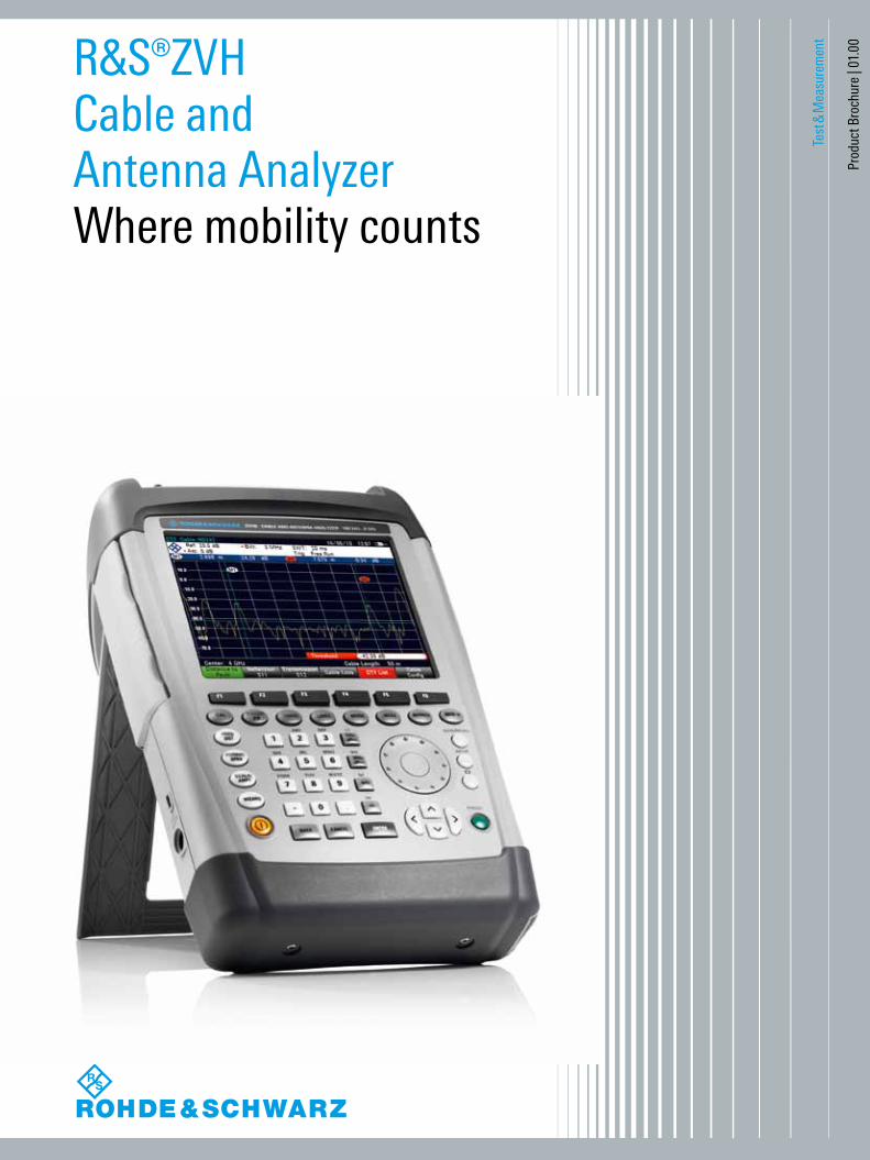
Distance-to-fault measurement at a mobile radio antenna system
with the R&S®ZVH.
2
When it comes to the installation or maintenance of antenna systems for mobile radio, broadcasting or radiocommunications, the R&S®ZVH cable and antenna analyzer performs fast, reliable and highly accurate mea-surements. Even in its basic configuration, the R&S®ZVH detects cable faults, measures the matching of filters and amplifiers and checks the loss of cable connections – the three most important tasks involved in setting up transmit-ter systems and putting them into operation. For further measurements such as the isolation between transmit and receive antennas or the output power of output amplifiers, suitable options are available to the RF service engineer or maintenance team.
Weighing only 3 kg, the R&S®ZVH is a handy instrument. Frequently used functions have their own function keys and are within reach of your fingertips. The built-in wizard lets users perform even extended test sequences fast and flawlessly. The R&S®ZVHView software makes it easy to generate test reports in just a few operating steps.
The brilliant color display is easy to read even under poor lighting conditions, and it has a monochrome mode for extreme conditions. The capacity of the R&S®ZVH battery enables uninterrupted operation for up to 4.5 hours. The battery is changed within seconds. And if it rains? No problem – all connectors are splash-proof.
Key facts Frequency range from 100 kHz to 3.6 GHz or 8 GHz 100 dB (typ.) dynamic range for filter and antenna isolation measurements
Built-in DC voltage supply (bias) for active components such as amplifiers
Power meter option Saving of measurement results on SD memory card or USB memory stick
Easy operation with user-configurable test sequences (wizard)
Easy-to-replace Li-ion battery for up to 4.5 h of operation Rugged, splash-proof housing for rough work in the field Easy handling due to low weight (3 kg with battery) and easy-to-reach function keys
The R&S®ZVH cable and antenna analyzer is rugged, handy and designed for use in the field. Its low weight and simple operation make it indispensable for anyone who needs an efficient measuring instrument outdoors for the installation and maintenance of antenna systems.
R&S®ZVH Cable and Antenna AnalyzerAt a glance
Rohde & Schwarz R&S®ZVH Cable and Antenna Analyzer 3
R&S®ZVH Cable and Antenna AnalyzerBenefits and key features
Installation and maintenance of antenna systems Distance-to-fault measurements One-port cable loss measurements Reflection measurements Transmission measurements Built-in DC voltage supply Terminating power measurements Directional power measurements Position finding using GPS receiver ▷ page 4
Easy operation Test report in just a few steps using the R&S®ZVH wizard Channel tables for frequency setting Optimal reading of measurement results in any situation Operation in different languages Easy-to-access, well-protected connectors ▷ page 8
Documentation and remote control R&S®ZVHView software for documenting measurement results
Remote control via LAN or USB ▷ page 12
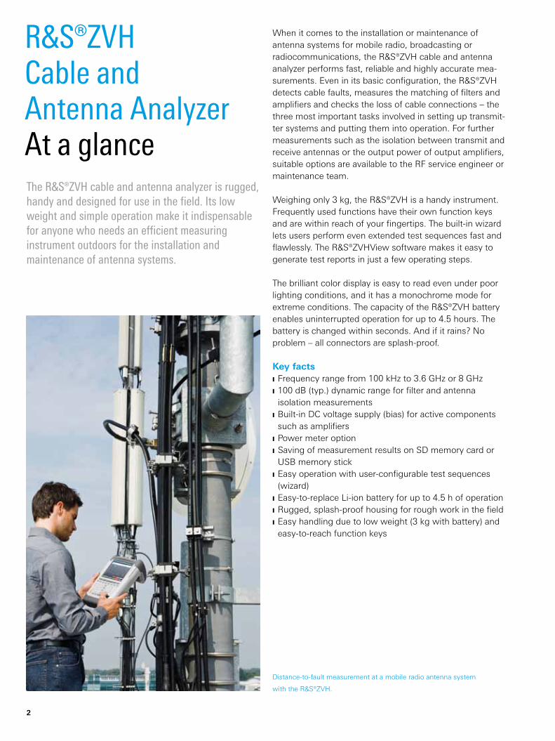
Easy-to-replace Li-ion battery for up to 4.5 h of operation.
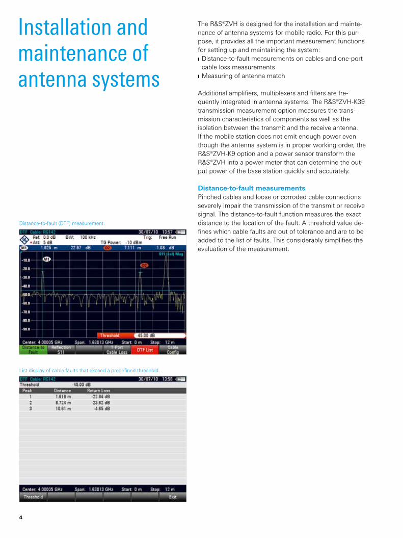
Distance-to-fault (DTF) measurement.
List display of cable faults that exceed a predefined threshold.
4
The R&S®ZVH is designed for the installation and mainte-nance of antenna systems for mobile radio. For this pur-pose, it provides all the important measurement functions for setting up and maintaining the system: Distance-to-fault measurements on cables and one-port cable loss measurements
Measuring of antenna match
Additional amplifiers, multiplexers and filters are fre-quently integrated in antenna systems. The R&S®ZVH-K39 transmission measurement option measures the trans-mission characteristics of components as well as the isolation between the transmit and the receive antenna. If the mobile station does not emit enough power even though the antenna system is in proper working order, the R&S®ZVH-K9 option and a power sensor transform the R&S®ZVH into a power meter that can determine the out-put power of the base station quickly and accurately.
Distance-to-fault measurementsPinched cables and loose or corroded cable connections severely impair the transmission of the transmit or receive signal. The distance-to-fault function measures the exact distance to the location of the fault. A threshold value de-fines which cable faults are out of tolerance and are to be added to the list of faults. This considerably simplifies the evaluation of the measurement.
Installation and maintenance of antenna systems
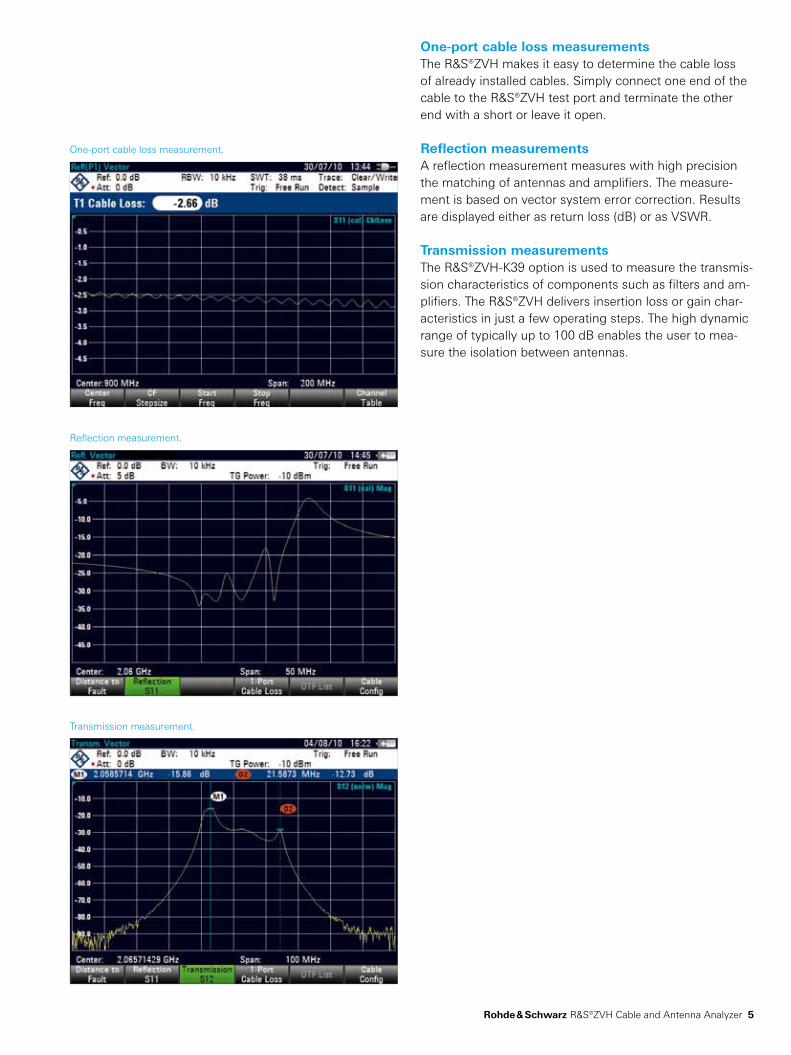
One-port cable loss measurement.
Reflection measurement.
Transmission measurement.
Rohde & Schwarz R&S®ZVH Cable and Antenna Analyzer 5
One-port cable loss measurementsThe R&S®ZVH makes it easy to determine the cable loss of already installed cables. Simply connect one end of the cable to the R&S®ZVH test port and terminate the other end with a short or leave it open.
Reflection measurements A reflection measurement measures with high precision the matching of antennas and amplifiers. The measure-ment is based on vector system error correction. Results are displayed either as return loss (dB) or as VSWR.
Transmission measurements The R&S®ZVH-K39 option is used to measure the transmis-sion characteristics of components such as filters and am-plifiers. The R&S®ZVH delivers insertion loss or gain char-acteristics in just a few operating steps. The high dynamic range of typically up to 100 dB enables the user to mea-sure the isolation between antennas.
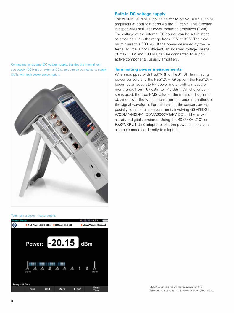
Terminating power measurement.
Connectors for external DC voltage supply: Besides the internal volt-
age supply (DC bias), an external DC source can be connected to supply
DUTs with high power consumption.
6
Built-in DC voltage supplyThe built-in DC bias supplies power to active DUTs such as amplifiers at both test ports via the RF cable. This function is especially useful for tower-mounted amplifiers (TMA). The voltage of the internal DC source can be set in steps as small as 1 V in the range from 12 V to 32 V. The maxi-mum current is 500 mA. If the power delivered by the in-ternal source is not sufficient, an external voltage source of max. 50 V and 600 mA can be connected to supply active components, usually amplifiers.
Terminating power measurementsWhen equipped with R&S®NRP or R&S®FSH terminating power sensors and the R&S®ZVH-K9 option, the R&S®ZVH becomes an accurate RF power meter with a measure-ment range from –67 dBm to +45 dBm. Whichever sen-sor is used, the true RMS value of the measured signal is obtained over the whole measurement range regardless of the signal waveform. For this reason, the sensors are es-pecially suitable for measurements involving GSM/EDGE, WCDMA/HSDPA, CDMA2000®/1xEV-DO or LTE as well as future digital standards. Using the R&S®FSH-Z101 or R&S®NRP-Z4 USB adapter cable, the power sensors can also be connected directly to a laptop.
CDMA2000® is a registered trademark of the Telecommunications Industry Association (TIA - USA).
The R&S®ZVH with terminating power sensor.
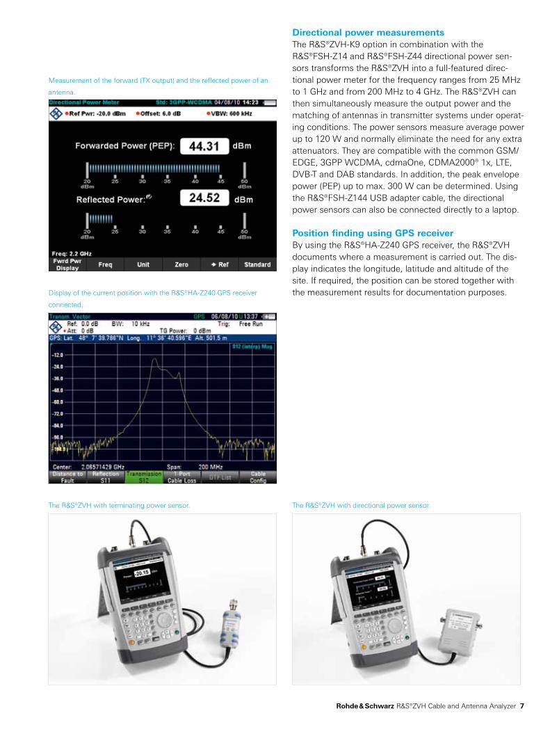
Measurement of the forward (TX output) and the reflected power of an
antenna.
The R&S®ZVH with directional power sensor.
Display of the current position with the R&S®HA-Z240 GPS receiver
connected.
Rohde & Schwarz R&S®ZVH Cable and Antenna Analyzer 7
Directional power measurements The R&S®ZVH-K9 option in combination with the R&S®FSH-Z14 and R&S®FSH-Z44 directional power sen-sors transforms the R&S®ZVH into a full-featured direc-tional power meter for the frequency ranges from 25 MHz to 1 GHz and from 200 MHz to 4 GHz. The R&S®ZVH can then simultaneously measure the output power and the matching of antennas in transmitter systems under operat-ing conditions. The power sensors measure average power up to 120 W and normally eliminate the need for any extra attenuators. They are compatible with the common GSM/EDGE, 3GPP WCDMA, cdmaOne, CDMA2000® 1x, LTE, DVB-T and DAB standards. In addition, the peak envelope power (PEP) up to max. 300 W can be determined. Using the R&S®FSH-Z144 USB adapter cable, the directional power sensors can also be connected directly to a laptop.
Position finding using GPS receiver By using the R&S®HA-Z240 GPS receiver, the R&S®ZVH documents where a measurement is carried out. The dis-play indicates the longitude, latitude and altitude of the site. If required, the position can be stored together with the measurement results for documentation purposes.
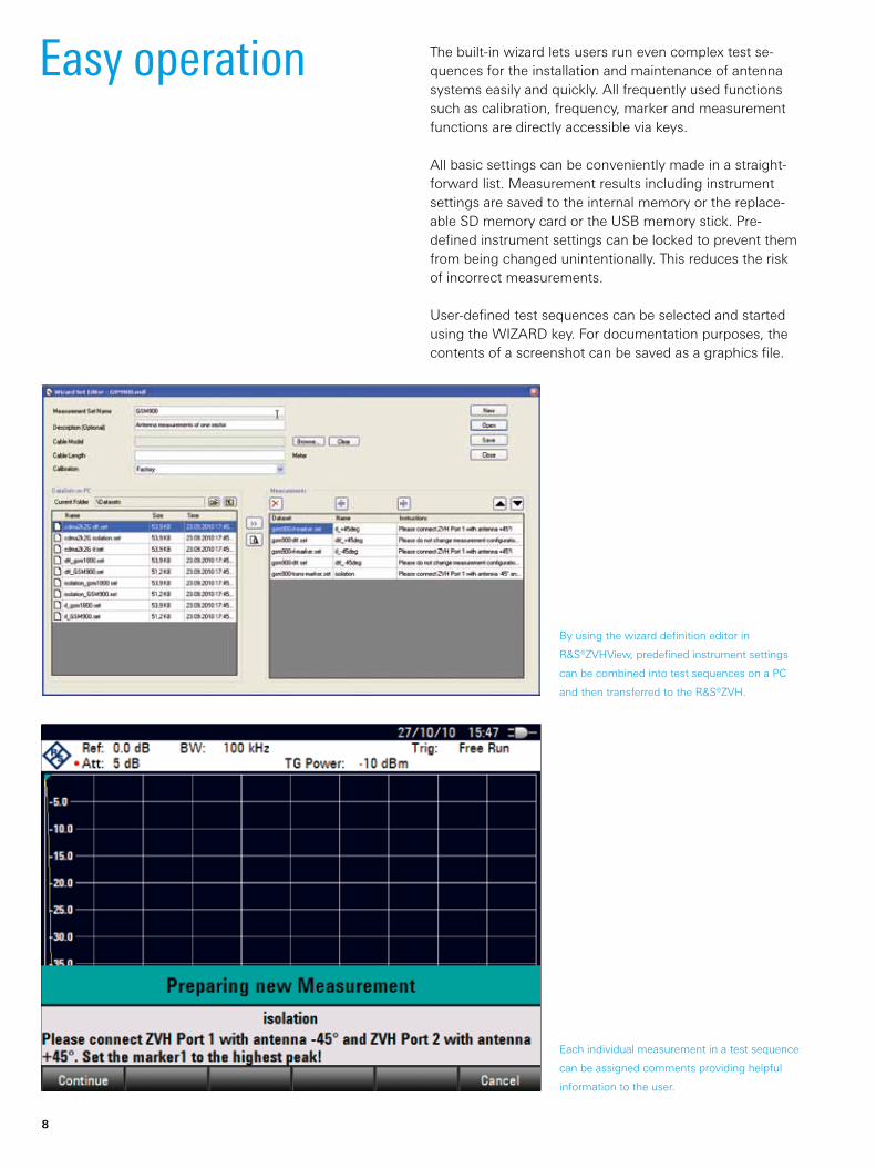
By using the wizard definition editor in
R&S®ZVHView, predefined instrument settings
can be combined into test sequences on a PC
and then transferred to the R&S®ZVH.
Each individual measurement in a test sequence
can be assigned comments providing helpful
information to the user.
8
The built-in wizard lets users run even complex test se-quences for the installation and maintenance of antenna systems easily and quickly. All frequently used functions such as calibration, frequency, marker and measurement functions are directly accessible via keys.
All basic settings can be conveniently made in a straight-forward list. Measurement results including instrument settings are saved to the internal memory or the replace-able SD memory card or the USB memory stick. Pre-defined instrument settings can be locked to prevent them from being changed unintentionally. This reduces the risk of incorrect measurements.
User-defined test sequences can be selected and started using the WIZARD key. For documentation purposes, the contents of a screenshot can be saved as a graphics file.
Easy operation
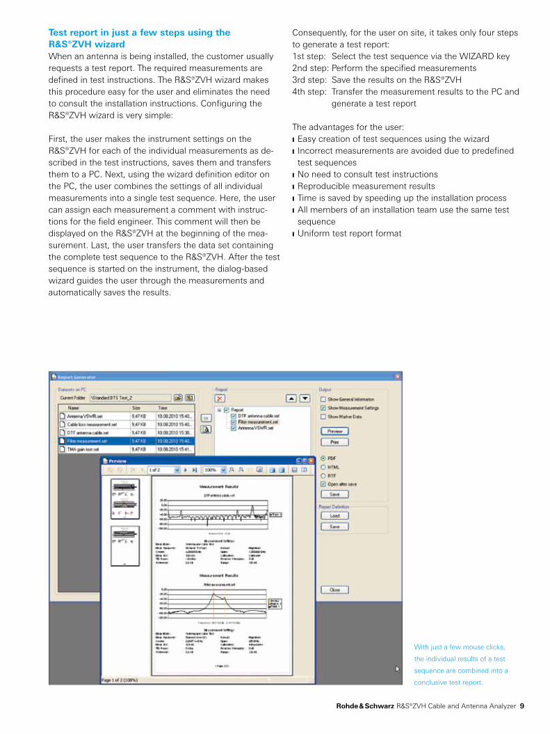
With just a few mouse clicks,
the individual results of a test
sequence are combined into a
conclusive test report.
Rohde & Schwarz R&S®ZVH Cable and Antenna Analyzer 9
Consequently, for the user on site, it takes only four steps to generate a test report:1st step: Select the test sequence via the WIZARD key2nd step: Perform the specified measurements3rd step: Save the results on the R&S®ZVH4th step: Transfer the measurement results to the PC and
generate a test report
The advantages for the user: Easy creation of test sequences using the wizard Incorrect measurements are avoided due to predefined test sequences
No need to consult test instructions Reproducible measurement results Time is saved by speeding up the installation process All members of an installation team use the same test sequence
Uniform test report format
Test report in just a few steps using the R&S®ZVH wizardWhen an antenna is being installed, the customer usually requests a test report. The required measurements are defined in test instructions. The R&S®ZVH wizard makes this procedure easy for the user and eliminates the need to consult the installation instructions. Configuring the R&S®ZVH wizard is very simple:
First, the user makes the instrument settings on the R&S®ZVH for each of the individual measurements as de-scribed in the test instructions, saves them and transfers them to a PC. Next, using the wizard definition editor on the PC, the user combines the settings of all individual measurements into a single test sequence. Here, the user can assign each measurement a comment with instruc-tions for the field engineer. This comment will then be displayed on the R&S®ZVH at the beginning of the mea-surement. Last, the user transfers the data set containing the complete test sequence to the R&S®ZVH. After the test sequence is started on the instrument, the dialog-based wizard guides the user through the measurements and automatically saves the results.
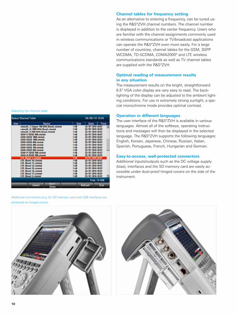
Additional connectors (e.g. for SD memory card and USB interface) are
protected by hinged covers.
Selecting the channel table.
10
Channel tables for frequency settingAs an alternative to entering a frequency, can be tuned us-ing the R&S®ZVH channel numbers. The channel number is displayed in addition to the center frequency. Users who are familiar with the channel assignments commonly used in wireless communications or TV/broadcast applications can operate the R&S®ZVH even more easily. For a large number of countries, channel tables for the GSM, 3GPP WCDMA, TD-SCDMA, CDMA2000® and LTE wireless communications standards as well as TV channel tables are supplied with the R&S®ZVH.
Optimal reading of measurement results in any situationThe measurement results on the bright, straightforward 6.5" VGA color display are very easy to read. The back-lighting of the display can be adjusted to the ambient light-ing conditions. For use in extremely strong sunlight, a spe-cial monochrome mode provides optimal contrast.
Operation in different languagesThe user interface of the R&S®ZVH is available in various languages. Almost all of the softkeys, operating instruc-tions and messages will then be displayed in the selected language. The R&S®ZVH supports the following languages: English, Korean, Japanese, Chinese, Russian, Italian, Spanish, Portuguese, French, Hungarian and German.
Easy-to-access, well-protected connectorsAdditional inputs/outputs such as the DC voltage supply (bias), interfaces and the SD memory card are easily ac-cessible under dust-proof hinged covers on the side of the instrument.
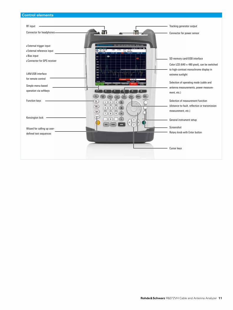
Control elements
RF input
Connector for headphones
J External trigger input
J External reference input
J Bias input
J Connector for GPS receiver
LAN/USB interface
for remote control
Simple menu-based
operation via softkeys
Function keys
Kensington lock
Wizard for calling up user-
defined test sequences
Connector for power sensor
Tracking generator output
SD memory card/USB interface
Color LCD (640 × 480 pixel), can be switched
to high-contrast monochrome display in
extreme sunlight
Selection of operating mode (cable and
antenna measurements, power measure-
ment, etc.)
Selection of measurement function
( distance-to-fault, reflection or transmission
measurement, etc.)
General instrument setup
Screenshot
Rotary knob with Enter button
Cursor keys
Rohde & Schwarz R&S®ZVH Cable and Antenna Analyzer 11
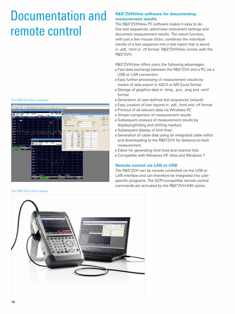
The R&S®ZVHView software.
The R&S®ZVH with a laptop.
12
Documentation and remote control
R&S®ZVHView software for documenting measurement resultsThe R&S®ZVHView PC software makes it easy to de-fine test sequences, administer instrument settings and document measurement results. The report function, with just a few mouse clicks, combines the individual results of a test sequence into a test report that is saved in .pdf, .html or .rtf format. R&S®ZVHView comes with the R&S®ZVH.
R&S®ZVHView offers users the following advantages: Fast data exchange between the R&S®ZVH and a PC via a USB or LAN connection
Easy further processing of measurement results by means of data export in ASCII or MS Excel format
Storage of graphics data in .bmp, .pcx, .png and .wmf format
Generation of user-defined test sequences (wizard) Easy creation of test reports in. pdf, .html and .rtf format Printout of all relevant data via Windows PC Simple comparison of measurement results Subsequent analysis of measurement results by displaying/hiding and shifting markers
Subsequent display of limit lines Generation of cable data using an integrated cable editor and downloading to the R&S®ZVH for distance-to-fault measurement
Editor for generating limit lines and channel lists Compatible with Windows XP, Vista and Windows 7
Remote control via LAN or USBThe R&S®ZVH can be remote controlled via the USB or LAN interface and can therefore be integrated into user-specific programs. The SCPI-compatible remote control commands are activated by the R&S®ZVH-K40 option.
Rohde & Schwarz R&S®ZVH Cable and Antenna Analyzer 13
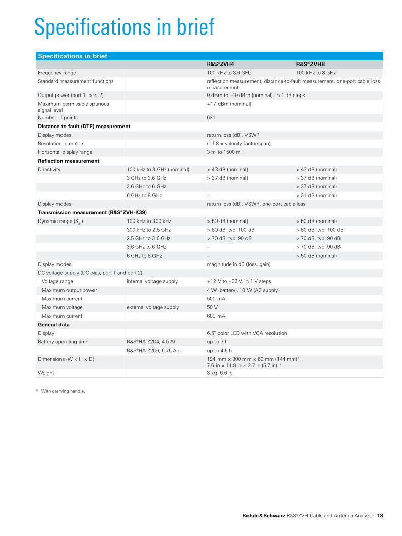
Specifications in briefSpecifications in brief
R&S®ZVH4 R&S®ZVH8
Frequency range 100 kHz to 3.6 GHz 100 kHz to 8 GHz
Standard measurement functions reflection measurement, distance-to-fault measurement, one-port cable loss measurement
Output power (port 1, port 2) 0 dBm to –40 dBm (nominal), in 1 dB steps
Maximum permissible spurious signal level
+17 dBm (nominal)
Number of points 631
Distance-to-fault (DTF) measurement
Display modes return loss (dB), VSWR
Resolution in meters (1.58 × velocity factor/span)
Horizontal display range 3 m to 1500 m
Reflection measurement
Directivity 100 kHz to 3 GHz (nominal) > 43 dB (nominal) > 43 dB (nominal)
3 GHz to 3.6 GHz > 37 dB (nominal) > 37 dB (nominal)
3.6 GHz to 6 GHz – > 37 dB (nominal)
6 GHz to 8 GHz – > 31 dB (nominal)
Display modes return loss (dB), VSWR, one-port cable loss
Transmission measurement (R&S®ZVH-K39)
Dynamic range (S21) 100 kHz to 300 kHz > 50 dB (nominal) > 50 dB (nominal)
300 kHz to 2.5 GHz > 80 dB, typ. 100 dB > 80 dB, typ. 100 dB
2.5 GHz to 3.6 GHz > 70 dB, typ. 90 dB > 70 dB, typ. 90 dB
3.6 GHz to 6 GHz – > 70 dB, typ. 90 dB
6 GHz to 8 GHz – > 50 dB (nominal)
Display modes magnitude in dB (loss, gain)
DC voltage supply (DC bias, port 1 and port 2)
Voltage range internal voltage supply +12 V to +32 V, in 1 V steps
Maximum output power 4 W (battery), 10 W (AC supply)
Maximum current 500 mA
Maximum voltage external voltage supply 50 V
Maximum current 600 mA
General data
Display 6.5" color LCD with VGA resolution
Battery operating time R&S®HA-Z204, 4.5 Ah up to 3 h
R&S®HA-Z206, 6.75 Ah up to 4.5 h
Dimensions (W × H × D) 194 mm × 300 mm × 69 mm (144 mm) 1),7.6 in × 11.8 in × 2.7 in (5.7 in) 1)
Weight 3 kg, 6.6 lb
1) With carrying handle.
14
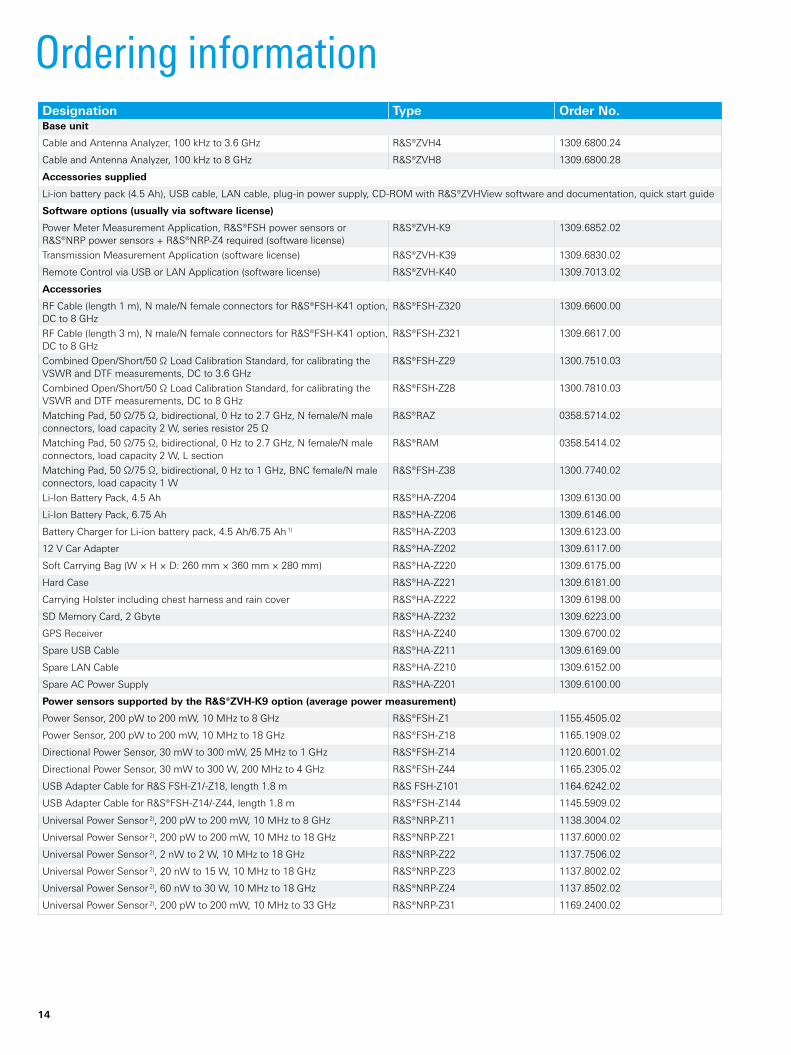
Ordering informationDesignation Type Order No.Base unit
Cable and Antenna Analyzer, 100 kHz to 3.6 GHz R&S®ZVH4 1309.6800.24
Cable and Antenna Analyzer, 100 kHz to 8 GHz R&S®ZVH8 1309.6800.28
Accessories supplied
Li-ion battery pack (4.5 Ah), USB cable, LAN cable, plug-in power supply, CD-ROM with R&S®ZVHView software and documentation, quick start guide
Software options (usually via software license)
Power Meter Measurement Application, R&S®FSH power sensors or R&S®NRP power sensors + R&S®NRP-Z4 required (software license)
R&S®ZVH-K9 1309.6852.02
Transmission Measurement Application (software license) R&S®ZVH-K39 1309.6830.02
Remote Control via USB or LAN Application (software license) R&S®ZVH-K40 1309.7013.02
Accessories
RF Cable (length 1 m), N male/N female connectors for R&S®FSH-K41 option, DC to 8 GHz
R&S®FSH-Z320 1309.6600.00
RF Cable (length 3 m), N male/N female connectors for R&S®FSH-K41 option, DC to 8 GHz
R&S®FSH-Z321 1309.6617.00
Combined Open/Short/50 Ω Load Calibration Standard, for calibrating the VSWR and DTF measurements, DC to 3.6 GHz
R&S®FSH-Z29 1300.7510.03
Combined Open/Short/50 Ω Load Calibration Standard, for calibrating the VSWR and DTF measurements, DC to 8 GHz
R&S®FSH-Z28 1300.7810.03
Matching Pad, 50 Ω/75 Ω, bidirectional, 0 Hz to 2.7 GHz, N female/N male connectors, load capacity 2 W, series resistor 25 Ω
R&S®RAZ 0358.5714.02
Matching Pad, 50 Ω/75 Ω, bidirectional, 0 Hz to 2.7 GHz, N female/N male connectors, load capacity 2 W, L section
R&S®RAM 0358.5414.02
Matching Pad, 50 Ω/75 Ω, bidirectional, 0 Hz to 1 GHz, BNC female/N male connectors, load capacity 1 W
R&S®FSH-Z38 1300.7740.02
Li-Ion Battery Pack, 4.5 Ah R&S®HA-Z204 1309.6130.00
Li-Ion Battery Pack, 6.75 Ah R&S®HA-Z206 1309.6146.00
Battery Charger for Li-ion battery pack, 4.5 Ah/6.75 Ah 1) R&S®HA-Z203 1309.6123.00
12 V Car Adapter R&S®HA-Z202 1309.6117.00
Soft Carrying Bag (W × H × D: 260 mm × 360 mm × 280 mm) R&S®HA-Z220 1309.6175.00
Hard Case R&S®HA-Z221 1309.6181.00
Carrying Holster including chest harness and rain cover R&S®HA-Z222 1309.6198.00
SD Memory Card, 2 Gbyte R&S®HA-Z232 1309.6223.00
GPS Receiver R&S®HA-Z240 1309.6700.02
Spare USB Cable R&S®HA-Z211 1309.6169.00
Spare LAN Cable R&S®HA-Z210 1309.6152.00
Spare AC Power Supply R&S®HA-Z201 1309.6100.00
Power sensors supported by the R&S®ZVH-K9 option (average power measurement)
Power Sensor, 200 pW to 200 mW, 10 MHz to 8 GHz R&S®FSH-Z1 1155.4505.02
Power Sensor, 200 pW to 200 mW, 10 MHz to 18 GHz R&S®FSH-Z18 1165.1909.02
Directional Power Sensor, 30 mW to 300 mW, 25 MHz to 1 GHz R&S®FSH-Z14 1120.6001.02
Directional Power Sensor, 30 mW to 300 W, 200 MHz to 4 GHz R&S®FSH-Z44 1165.2305.02
USB Adapter Cable for R&S FSH-Z1/-Z18, length 1.8 m R&S FSH-Z101 1164.6242.02
USB Adapter Cable for R&S®FSH-Z14/-Z44, length 1.8 m R&S®FSH-Z144 1145.5909.02
Universal Power Sensor 2), 200 pW to 200 mW, 10 MHz to 8 GHz R&S®NRP-Z11 1138.3004.02
Universal Power Sensor 2), 200 pW to 200 mW, 10 MHz to 18 GHz R&S®NRP-Z21 1137.6000.02
Universal Power Sensor 2), 2 nW to 2 W, 10 MHz to 18 GHz R&S®NRP-Z22 1137.7506.02
Universal Power Sensor 2), 20 nW to 15 W, 10 MHz to 18 GHz R&S®NRP-Z23 1137.8002.02
Universal Power Sensor 2), 60 nW to 30 W, 10 MHz to 18 GHz R&S®NRP-Z24 1137.8502.02
Universal Power Sensor 2), 200 pW to 200 mW, 10 MHz to 33 GHz R&S®NRP-Z31 1169.2400.02
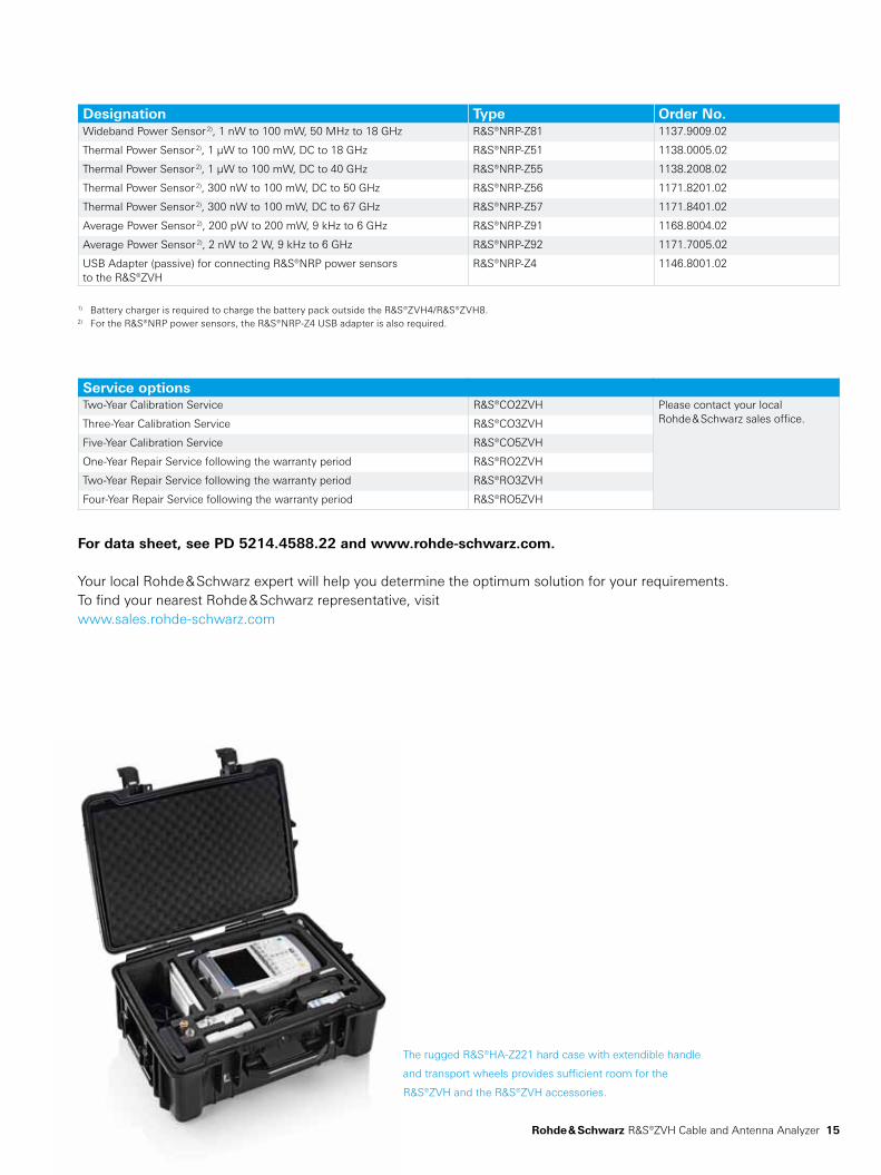
The rugged R&S®HA-Z221 hard case with extendible handle
and transport wheels provides sufficient room for the
R&S®ZVH and the R&S®ZVH accessories.
Rohde & Schwarz R&S®ZVH Cable and Antenna Analyzer 15
Designation Type Order No.Wideband Power Sensor 2), 1 nW to 100 mW, 50 MHz to 18 GHz R&S®NRP-Z81 1137.9009.02
Thermal Power Sensor 2), 1 µW to 100 mW, DC to 18 GHz R&S®NRP-Z51 1138.0005.02
Thermal Power Sensor 2), 1 µW to 100 mW, DC to 40 GHz R&S®NRP-Z55 1138.2008.02
Thermal Power Sensor 2), 300 nW to 100 mW, DC to 50 GHz R&S®NRP-Z56 1171.8201.02
Thermal Power Sensor 2), 300 nW to 100 mW, DC to 67 GHz R&S®NRP-Z57 1171.8401.02
Average Power Sensor 2), 200 pW to 200 mW, 9 kHz to 6 GHz R&S®NRP-Z91 1168.8004.02
Average Power Sensor 2), 2 nW to 2 W, 9 kHz to 6 GHz R&S®NRP-Z92 1171.7005.02
USB Adapter (passive) for connecting R&S®NRP power sensors to the R&S®ZVH
R&S®NRP-Z4 1146.8001.02
1) Battery charger is required to charge the battery pack outside the R&S®ZVH4/R&S®ZVH8.2) For the R&S®NRP power sensors, the R&S®NRP-Z4 USB adapter is also required.
Service optionsTwo-Year Calibration Service R&S®CO2ZVH Please contact your local
Rohde & Schwarz sales office.Three-Year Calibration Service R&S®CO3ZVH
Five-Year Calibration Service R&S®CO5ZVH
One-Year Repair Service following the warranty period R&S®RO2ZVH
Two-Year Repair Service following the warranty period R&S®RO3ZVH
Four-Year Repair Service following the warranty period R&S®RO5ZVH
For data sheet, see PD 5214.4588.22 and www.rohde-schwarz.com.
Your local Rohde & Schwarz expert will help you determine the optimum solution for your requirements.To find your nearest Rohde & Schwarz representative, visitwww.sales.rohde-schwarz.com
R&S® is a registered trademark of Rohde & Schwarz GmbH & Co. KG
Trade names are trademarks of the owners | Printed in Germany (ch)
PD 5214.4588.12 | Version 01.00 | October 2010 | R&S®ZVH
Data without tolerance limits is not binding | Subject to change
© 2010 Rohde & Schwarz GmbH & Co. KG | 81671 München, Germany
About Rohde & SchwarzRohde & Schwarz is an independent group of companies specializing in electronics. It is a leading supplier of solu-tions in the fields of test and measurement, broadcast-ing, radiomonitoring and radiolocation, as well as secure communications. Established more than 75 years ago, Rohde & Schwarz has a global presence and a dedicated service network in over 70 countries. Company headquar-ters are in Munich, Germany.
Environmental commitment Energy-efficient products Continuous improvement in environmental sustainability ISO 14001-certified environmental management system
Certified Quality System
ISO 9001
Rohde & Schwarz GmbH & Co. KGwww.rohde-schwarz.com
Regional contact Europe, Africa, Middle East +49 89 4129 123 45 [email protected]
North America 1 888 TEST RSA (1 888 837 87 72) [email protected]
Latin America +1 410 910 79 88 [email protected]
Asia/Pacific +65 65 13 04 88 [email protected]
Service you can rely onJ Worldwide J Local and personalizedJ Customized and flexibleJ Uncompromising qualityJ Long-term dependability
5214458812