Embed Size (px)
Citation preview

121
LAB
OBJECTIVES The objective of this lab is to study the Resource Reservation Protocol (RSVP) as part of the integrated services approach that provides quality of service (QoS) to individual applications or fl ows.
OVERVIEW For many years, packet-switched networks have offered the promise of supporting multime-dia applications. Multimedia applications combine audio, video, and data. Audio and video applications are examples of real-time applications. In the best-effort model, the network tries to deliver your data but makes no promises and leaves the “cleanup operation” to the edges. This model is not suffi cient for real-time applications. What we need is a new service model—one in which applications that need better assurances can request such service from the network. The network may then respond by providing an assurance that it will do better or perhaps by saying that it cannot promise anything better at the moment. A network that can provide different levels of service is often said to support QoS.
Two approaches have been developed to provide a range of QoS: integrated services and differentiated services. The Resource Reservation Protocol (RSVP) follows the integrated services approach, whereby QoS is provided to individual applications or fl ows. The differentiated services approach provides QoS to large classes of data or aggregated traffi c.
Although connection-oriented networks have always needed some sort of setup protocol to establish the necessary virtual circuit state in the routers, connectionless networks, like the Internet, have had no such protocols. One of the key assumptions underlying RSVP is that it should not detract from the robustness that we fi nd in the Internet. Therefore, RSVP uses the idea of soft state in the routers. Soft state—in contrast to the hard state found in connection-oriented networks—does not need to be explicitly deleted when it is no longer needed. Instead, it times out after some fairly short period if it is not periodically refreshed. RSVP adopts the receiver-oriented approach, where the receivers keep track of their own resource requirements, and they periodically send refresh messages to keep the soft state in place.
RSVP: Resource Reservation Protocol Providing QoS by Reserving Resources in the Network
12

Network Simulation Experiments Manual
122
In this lab, you will set up a network that carries real-time applications and that utilizes RSVP to provide QoS to one of these applications. You will study how RSVP contributes to the performance of the application that makes use of it.
PRE-LAB ACTIVITIES & Read Section 6.5.2 from Computer Networks: A Systems Approach, 5th Edition .
: Go to www.net-seal.net and play the following animation: ❍ TCP Flow Control
PROCEDURE Create the Project 1. Start OPNET IT Guru Academic Edition · Choose Open from the menu. 2. Select the project you created in the “Queuing Disciplines” lab: <your initials>_Queues ·
Click OK . 3. From the File menu, choose Save As · Rename the project to <your initials>_RSVP ·
Click OK . 4. From the Scenarios menu, choose Manage Scenarios · Click on FIFO · Click Delete ·
Click on PQ · Click Delete .
5. Click on WFQ , and rename it to QoS_RSVP · Click OK . 6. Make sure that you have only the QoS_RSVP scenario in your project. The following
fi gure shows one way to check the available scenarios in the project. 7. Save your project.
Confi gure the Network Add more VoIP nodes:
In this project, we will set up the two VoIP nodes so that one will always be the Caller party and the other will be the Called party. In addition, we will add two new VoIP Caller and Called nodes. These new nodes will utilize RSVP to reserve their required resources through the network.
The idea of the FQ (fair queuing) discipline is to maintain a separate queue for each fl ow currently being handled by the router . The router then services these queues in a round-robin manner. WFQ allows a weight to be assigned to each fl ow (queue). This weight effectively controls the percentage of the link’s bandwidth each fl ow receives. We could use the ToS (Type of Service) fi eld in the IP header to identify that weight.

LAB 12 RSVP: Resource Reser vation Protocol
123
1. Right-click on the VoIP East node · Edit Attributes · Rename the node to Voice Called · Assign None to the Application: Supported Profi les attribute · Assign Voice Called to the Client Address attribute · Click OK .
2. Right-click on the VoIP West node · Edit Attributes . a. Rename the node to Voice Caller . b. Assign None to the Application: Supported Services attribute. c. Edit the value of the Application: Destination Preferences attribute · Set Rows to 1 ·
Assign Voice Destination to the Symbolic Name of the new row · Edit the Actual Name attribute · Set Rows to 1 · Assign Voice Called to the Name attribute of the new row as shown.
3. Click OK three times, and Save your project.
4. Click on the Voice Called node to select it · From the Edit menu, select Copy · From the Edit menu, select Paste (alternatively, use the standard keyboard shortcuts, Ctrl + C and Ctrl + V ). a. Locate the new node somewhere below the Voice Called node on the screen ·
Connect the new node to the East Router using a 10BaseT link. b. Right - click on the new node · Edit Attributes . c. Click on the ethernet_wkstn value of the model attribute · Select Edit · Select the
ethernet_wkstn_adv model. d. Rename it to Voice_RSVP Called · Assign Voice_RSVP Called to its Client Address
attribute. e. Click OK .
5. Copy and paste the Voice Caller node: a. Locate the new node somewhere below the Voice Caller node · Connect the new
node to the West Router using a 10BaseT link. b. Right-click on the new node · Edit Attributes · Click on the ethernet_wkstn value
of the model attribute · Select Edit · Select the ethernet_wkstn_adv model. c. Rename it to Voice_RSVP Caller . d. Edit the Application: Destination Preferences attribute · Open the Actual Name
table by clicking in the value fi eld of Actual Name · Assign Voice_RSVP Called to the Name attribute (this is to replace the current value, which is Voice Called ).
e. Click OK three times.

Network Simulation Experiments Manual
124
6. Rename the Queues node in the project to QoS . Your project should look like the dia-gram shown.
7. Save your project.
Defi ne the data fl ow:
Here we will defi ne the data fl ow characteristics of the voice traffi c in the network. The sender’s RSVP module periodically sends RSVP Path messages that use the data fl ow characteristics to describe the traffi c generated by the sender. When the receiver’s RSVP module receives the Path message, the receiver host application checks the characteristics of the requested data fl ow and decides whether resources should be reserved. Once a decision is made, the receiver host application sends a request to the host RSVP module to assist in the reservation setup. The receiver’s RSVP module then carries the request as Resv messages to all nodes along the reverse data path to the sender.
The fl ow is defi ned by its required bandwidth and buffer size. Bandwidth is set to be the token bucket rate in the fl ow specifi cation of the Path and Resv messages. The buffer size repre-sents the amount of the application “bursty” data to be buffered. It specifi es the token bucket size that will be set in the Path or Resv messages for the session.

LAB 12 RSVP: Resource Reser vation Protocol
125
1. Right-click on the QoS node · Edit Attributes . a. Expand the RSVP Flow Specifi cation hierarchy and its row 0 hierarchy · Set Name to
RSVP_Flow · Assign 50,000 to the Bandwidth (bytes/sec) attribute · Assign 10,000 to the Buffer Size (bytes) attribute.
b. Expand the RSVP Profi les hierarchy and its row 0 hierarchy · Set Profi le Name to RSVP_Profi le · Click OK , and Save your project.
RSVP Flow defi nes traffi c requirements (bandwidth and requested buffer size) for which RSVP reservation will be attempted.
Confi gure the application:
Here we will create a VoIP application that utilizes the RSVP fl ow specifi cations we confi gured.
1. Right-click on the Applications node · Edit Attributes · Expand the Applications Defi nitions hierarchy · Set rows to 4 (to add a fourth row to the Application Defi nitions attribute).

Network Simulation Experiments Manual
126
a. Name and set the attributes of row 3 as shown.
b. Click on the PCM Quality Speech value (shown in the previous fi gure) · Select Edit · Edit the value of the RSVP Parameters attribute · Assign the following values (recall that we defi ned the RSVP_Flow in the QoS node) · Click OK three times.

LAB 12 RSVP: Resource Reser vation Protocol
127
Note that the characteristics of the Outbound Flow are carried in the Path messages to be sent from sender to receiver, and the characteristics of the Inbound Flow parameters are carried in the Resv messages to be sent from the receiver to the sender.
Confi gure the profi le:
1. Right-click on the Profi les node · Edit Attributes · Expand the Profi le Confi guration hierarchy · Set rows to 4 · Name and set the attributes of row 0 as shown:
2. Click OK , and Save your project.
Confi gure the interfaces:
OPNET IT Guru supports RSVP on a per-interface basis; RSVP can be enabled or disabled for each node’s interface.

Network Simulation Experiments Manual
128
1. Simultaneously select (Shift + left-click) the three links shown:
2. From the Protocols menu, select RSVP · Select Confi gure Interface Status · Make the selections shown in the Confi gure dialog box · Click OK , and then Save your project.

LAB 12 RSVP: Resource Reser vation Protocol
129
This process enables RSVP on all interfaces along the path between the two voice parties that need to utilize RSVP.
Confi gure the hosts and routers:
In OPNET IT Guru, the RSVP process runs only in IP-enabled nodes. The advanced versions ( *_adv ) of those node models must be used, as we did already, to confi gure RSVP-related parameters. In addition, the RSVP model in OPNET IT Guru requires either WFQ or custom queuing schemes.
1. Right-click on the Voice_RSVP Caller node · Edit Attributes . a. Expand the Application: Supported Profi les hierarchy and its row 0 hierarchy ·
Assign VoIP_RSVP Profi le to the Profi le Name attribute. b. Expand the Application: RSVP Parameters hierarchy · Expand its Voice hierarchy ·
Enable the RSVP Status · Expand the Profi le List hierarchy · Assign to the Profi le attribute of row 0 the value RSVP_Profi le as shown.
c. Expand the IP Host Parameters hierarchy · Expand its Interface Information hierarchy · Expand the QoS Information hierarchy · Assign WFQ to the Queuing Scheme attribute · Assign ToS Based to the Queuing Profi le attribute · Assign RSVP Enabled to the RSVP Info attribute as shown.
Type of Service (ToS) is assigned to the IP packets. It represents a session attribute that allows packets to be provided the appropriate service in the IP queues.
Network Simulation Experiments Manual
130
e. Click OK . 2. Right-click on the Voice_RSVP Called node · Edit Attributes .
a. Edit the Application: Supported Services attribute. The Application: Supported Services Table will pop up · In that table, replace the VoIP Application with VoIP_RSVP and click OK .
b. Expand the Application: RSVP Parameters hierarchy · Expand its Voice hierarchy · Enable the RSVP Status · Expand the Profi le List hierarchy · Edit the value of the Profi le attribute of row 0 and enter RSVP_Profi le .
c. Expand the IP Host Parameters hierarchy · Expand its Interface Information hierarchy · Expand the QoS Information hierarchy · Assign WFQ to the Queuing Scheme attribute · Assign ToS Based to the Queuing Profi le attribute · Assign RSVP Enabled to the RSVP Info attribute.
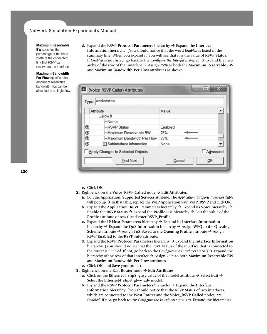
d. Expand the RSVP Protocol Parameters hierarchy · Expand the Interface Information hierarchy. (You should notice that the RSVP Status of the interface that is connected to the router is Enabled . If not, go back to the Confi gure the Interfaces steps.) · Expand the hierarchy of the row of that interface · Assign 75% to both Maximum Reservable BW and Maximum Bandwidth Per Flow attributes.
e. Click OK , and Save your project. 3. Right-click on the East Router node · Edit Attributes .
a. Click on the Ethernet4_slip8_gtwy value of the model attribute · Select Edit · Select the Ethernet4_slip8_gtwy_adv model.
b. Expand the RSVP Protocol Parameters hierarchy · Expand the Interface Information hierarchy. (You should notice that the RSVP Status of two interfaces, which are connected to the West Router and the Voice_RSVP Called nodes, are Enabled . If not, go back to the Confi gure the Interfaces steps.) · Expand the hierarchies
d. Expand the RSVP Protocol Parameters hierarchy · Expand the Interface Information hierarchy. (You should notice that the word Enabled is listed in the summary line. When you expand it, you will see that it is the value of RSVP Status . If Enabled is not listed, go back to the Confi gure the Interfaces steps.) · Expand the hier-archy of the row of that interface · Assign 75% to both the Maximum Reservable BW and Maximum Bandwidth Per Flow attributes as shown:
Maximum Reservable BW specifi es the percentage of the band-width of the connected link that RSVP can reserve on the interface.
Maximum Bandwidth Per Flow specifi es the amount of reservable bandwidth that can be allocated to a single fl ow.

LAB 12 RSVP: Resource Reser vation Protocol
131
of the rows of these two enabled interfaces · Assign 75% to both Maximum Reservable BW and Maximum Bandwidth Per Flow attributes.
c. Expand the IP Routing Parameters hierarchy · Expand the Interface Information hierarchy · Expand the hierarchies of the rows of the same two interfaces you con-fi gured in the previous step (step b) · Expand the QoS Information hierarchy for both · Set Queuing Scheme to WFQ and Queuing Profi le to ToS Based for both.
d. Click OK , and Save your project. 4. Right-click on the West Router node · Edit Attributes .
a. Click on the Ethernet4_slip8_gtwy value of the model attribute · Select Edit · Select the Ethernet4_slip8_gtwy_adv model.
b. Expand the RSVP Protocol Parameters hierarchy · Expand the Interface Information hierarchy. (You should notice that the RSVP Status of two interfaces, which are connected to the East Router and the Voice_RSVP Caller nodes, are Enabled . If not, go back to the Confi gure the Interfaces steps.) · Expand the hierar-chies of the rows of these two enabled interfaces · Assign 75% to both Maximum Reservable BW and Maximum Bandwidth Per Flow attributes.
c. Expand the IP Routing Parameters hierarchy · Expand the Interface Information hierarchy · Expand the hierarchies of the rows of the same two interfaces you con-fi gured in the previous step (step b) · Expand the QoS Information hierarchy for both · Set Queuing Scheme to WFQ and Queuing Profi le to ToS Based for both.
d. Click OK , and Save your project.
Choose the Statistics We will select statistics from three different nodes:
Voice_RSVP caller statistics:
1. Right-click on the Voice_ RSVP Caller node and select Choose Individual Statistics from the pop up menu.
2. Expand the RSVP hierarchy and select Number of Path States . 3. Right-click on the Number of Path States statistic · Select Change Draw Style from the
pop up menu · Choose bar chart . 4. Right-click on the Number of Path States statistic · Select Change Collection Mode
from the pop up menu · Check the Advanced checkbox · From the Capture mode drop-down menu, select all values, as shown · Click OK .
5. Expand the Voice Calling Party hierarchy and select the following statistics: Packet Delay Variation and Packet End-to-End Delay (sec) .
6. Click OK .
Voice_RSVP called statistics:
1. Right-click on the Voice_ RSVP Called node and select Choose Individual Statistics from the pop up menu.
2. Expand the RSVP hierarchy and select Number of Resv States . 3. Right-click on the Number of Resv States statistic · Select Change Draw Style from the
pop up menu · Choose bar chart . 4. Right-click on the Number of Resv States statistic · Select Change Collection Mode
from the pop up menu · Check the Advanced checkbox · From the Capture mode drop-down menu, select all values · Click OK twice.
Voice caller statistics:
1. Right-click on the Voice Caller node and select Choose Individual Statistics from the pop up menu.
2. Expand the Voice Calling Party hierarchy and select the following statistics: Packet Delay Variation and Packet End-to-End Delay (sec) ·Click OK .
Packet Delay Variation is the variance among end-to-end delays for voice packets received by this node.
Packet End-to-End Delay for a voice packet is measured from the time it is created to the time it is received.

Network Simulation Experiments Manual
132
Confi gure the Simulation Here we need to confi gure the duration of the simulation:
1. Click on and the Confi gure Simulation window should appear. 2. Make sure that the duration is set to 150 seconds . 3. Click on the Global Attributes tab and make sure that the following attribute
is enabled: a. RSVP Sim Effi ciency = Enabled . This decreases the simulation time and memory
requirements by not sending refresh messages (i.e., Path and Resv refreshes). 4. Click OK , and Save your project.
Run the Simulation To run the simulation:
1. Click on , and then click the Run button. Depending on the speed of your processor, this may take several seconds to complete.
2. After the simulation completes, click Close , and Save your project.
View the Results To view and analyze the results:
1. Select View Results from the Results menu. 2. As shown in the following fi gure, choose the Packet End-to-End Delay for both
the Voice Caller and Voice_RSVP Caller nodes. Choose Overlaid Statistics and time_average .
3. Click Show to get the following graph. ( Note: To zoom in on the graph, click and drag your mouse to draw a rectangle around the area of interest and release the mouse button.)

LAB 12 RSVP: Resource Reser vation Protocol
133 4. Similarly, you can get the following graph that compares the Packet Delay Variation for
both the Voice Caller and Voice_RSVP Caller nodes. ( Note: Make sure to “unselect” the statistics you chose for the previous graph.)

Network Simulation Experiments Manual
134
5. Finally, prepare the graph that displays the number of Path and Resv states by selecting the following statistics. Make sure to select Stacked Statistics and As Is as shown.
6. Click Show and Right-click on the resulting graph and choose Edit Panel Properties · Change the assigned values to the Horizontal Min and Horizontal Max fi elds as shown here:

LAB 12 RSVP: Resource Reser vation Protocol
135
7. Click OK . The resulting graph should resemble the one shown.
FURTHER READING OPNET RSVP Model Description: From the Protocols menu, select RSVP · Model Usage
Guide .
EXERCISES 1. Analyze the graphs we obtained in this lab. Show the effect of RSVP on the voice applica-
tion and explain the obtained numbers of Path and Resv states. 2. How does the data rate of the link connecting the East and West routers affect the perfor-
mance (e.g., Packet End-to-End Delay) of the voice and video conference applications? To answer this question, create a new scenario as a duplicate of the QoS_RSVP scenario. Name the new scenario Q2_HighRate . In the Q2_HighRate scenario, replace the current PPP_DS1 link (data rate 1.544 Mbps) with a PPP_DS3 link (data rate 44.736 Mbps).
LAB REPORT Prepare a report that follows the guidelines explained in the Introduction Lab. The report should include the answers to the preceding exercises as well as the graphs you generated from the simulation scenarios. Discuss the results you obtained, and compare these results with your expectations. Mention any anomalies or unexplained behaviors.


![IMS QoS title page - UPM · 2008-05-06 · DIAMETER, QoS signalling protocols like RSVP (Resource Reservation Protocol) and the recent NSIS [13] (Next Step in Signalling), IntServ](https://img.pdfslide.us/doc/110x75/5e6ee574403f2804f40a285e/ims-qos-title-page-2008-05-06-diameter-qos-signalling-protocols-like-rsvp-resource.jpg)