Embed Size (px)
Citation preview

Te
st &
Mea
sure
men
t
Prod
uct B
roch
ure
| 10.
00
R&S®TSMWUniversal Radio Network AnalyzerScanner for drive testsand I/Q streaming
TSMW_bro_en_5213-9934-12.indd 1 24.06.2014 15:05:21
2
R&S®TSMW Universal Radio Network AnalyzerAt a glanceThe R&S®TSMW universal radio network analyzer is a platform for optimizing all conventional wireless communications networks. Two frontends for any input frequency from 30 MHz to 6 GHz, preselection and software-defined architecture offer unsurpassed performance while providing maximum flexibility. In addition to functioning as a scanner for wireless communications networks, the R&S®TSMW is also an ideal digital I/Q baseband receiver.
Owing to its hardware platform, the R&S®TSMW universal radio network analyzer offers maximum flexibility. For example, the R&S®TSMW comes in handy as an LTE scanner, and it can be utilized together with the R&S®ROMES4 drive test software to roll out and optimize 3GPP EUTRA networks. In addition to LTE, other wireless communications technologies such as GSM, WCDMA,CDMA2000® 1xEV-DO,TETRAandWiMAX™are supported simultaneously.
Moreover, the R&S®TSMW can be used as a realtime scannerforI/Qbasebanddata.TheR&S®TSMW-K1option offers a MATLAB® and a C++ interface via which I/Q measurement data can be captured and evaluated.
Key facts ❙ User-definableinputfrequencyrangefrom30 MHzto6 GHz
❙ Two independent RF and signal processing paths, each withabandwidthofupto20 MHz
❙ Integrated preselection for high intermodulation suppression while dynamic range is high
❙ Support of LTEFDD and TDLTE ❙ Support of TDSCDMA ❙ Parallel measurements in GSM, WCDMA, LTE, CDMA2000®,1xEV-DO,TETRAandWiMAX™networkswith the R&S®ROMES4 drive test software
❙ Spectrum measurements with the RF power scan option ❙ I/Q baseband streaming and capturing ❙ Integrated GPS
TSMW_bro_en_5213-9934-12.indd 2 24.06.2014 15:05:22

Rohde & Schwarz R&S®TSMW Universal Radio Network Analyzer 3
R&S®TSMW Universal Radio Network AnalyzerBenefits and key features
LTE and MIMO network rollout and network optimization ❙ Automatic detection and measurement of all available cells
❙ MIMO-specificmeasurementsshowMIMOgain ❙ Intersymbol interference analysis with multipath measurements
❙ Narrowband and wideband measurements ❙ Support of LTEFDD and TDLTE ❙ Support of LTEA ❙ LTE downlink allocation analyzer ❙ Automatic channel detection ▷ page 4
All-in-one drive test solution with R&S®ROMES4 ❙ Network optimization with scanner and test terminal ❙ Improvement of QoS ▷ page 9
Parallel support of multiple wireless communications technologies ❙ Simultaneous measurements in GSM, LTE, WCDMA, CDMA2000®,1xEV-DO,TETRAandWiMAX™
❙ Simple scanner setup ❙ Flexible assignment of the two receivers for maximum measurement speed
❙ Everything in one instrument ▷ page10
Maximum flexibility when evaluating I/Q data ❙ Seamless streaming of I/Q data in realtime ❙ I/Q streaming via LAN ❙ I/Q streaming via Rohde & Schwarz I/Q interface ❙ Data access via MATLAB® or C++ interface ❙ Fast integration due to included example application based on MATLAB® ▷ page12
Unsurpassed hardware platform performance and flexibility ❙ Broadbandwith20 MHzbandwidthandmaximumfrequencyrangefrom30 MHzto6 GHz
❙ Maximumconfigurationflexibility ❙ Top dynamic range and measurement accuracy owing to adaptive preselection
❙ Update of hardware platform via software ❙ Integrated SuperSense GPS with PPS ❙ R&S®TSMF special solution ▷ page14
Supported by many drive test tools ❙ Open interfaces for integration into individual software solutions
❙ Flexibility in choice of drive test software ▷ page16
TSMW_bro_en_5213-9934-12.indd 3 24.06.2014 15:05:22

4
LTE and MIMO network rollout and network optimization
Using the R&S®TSMW together with the R&S®ROMES4 drive test software opens the door to numerous measurement and analysis capabilities for LTE field tests.
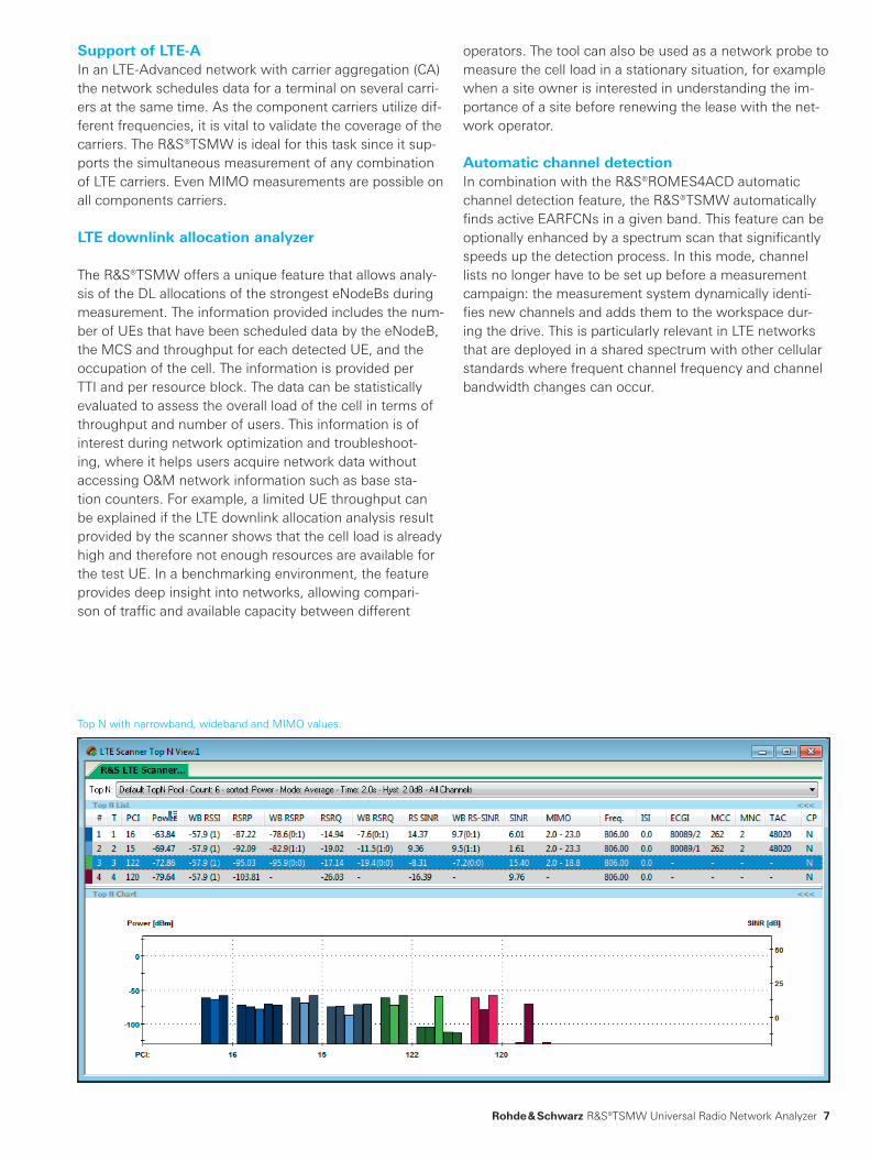
Automatic detection and measurement of all available cellsAll that the R&S®ROMES4 software needs to “know” is the centerfrequencyofanLTEsignal.TheR&S®TSMWcanfindallfurtherinformationthatisrequired,e.g.thebandwidth used, the physical cell ID, the eNodeB cell ID, the cyclicprefixlengthorthesynchronizationchannels(P-SCHandS-SCH)andRSRP/RSRQ/RS-SINRvalues.Thisisparticularly relevant when a wireless communications network is growing both in size and complexity. The user does notrequireanydetailedknowledgeabouttheLTEnetworkand its structure when carrying out measurements.
Immediately after the measurement is started, the power values of the physical cell IDs are displayed in a Top N chart.
In addition to these values, the RSRP, RSRQ and the narrowband and wideband signaltointerferenceplusnoise ratio(SINR)areoutput.Thesevaluesindicatewhetherinterference is present on a signal. The syncsignal measurement results can be output at a maximum rate of 200 measurements/s.
Condition number per resource block.
TSMW_bro_en_5213-9934-12.indd 4 24.06.2014 15:05:22

MIMO configuration
TX1
TX2
RX1TX1
TX2
TX1
TX2
TX1:RX1 TX1:RX2TX2:RX1 TX2:RX2
RX2
Subc
arrie
rs
Symbols
Subc
arrie
rs
Symbols
R1
R1
R1
R1
R1
R1
R1
R1
R1
R1
R1
R1
R1
R1
R1
R1
Rohde & Schwarz R&S®TSMW Universal Radio Network Analyzer 5
MIMO-specific measurements show MIMO gainA special MIMO measurement using the two internal R&S®TSMW receivers measures the true MIMO gain under realworld conditions. Two antennas simultaneously measure the LTE signal, making it possible to determine the degree of correlation of the MIMO channel. This indicates whether MIMO can profitably be used in the measured area and whether investments to expand the infrastructure will pay off.
The MIMO measurement function can be used for 4x2 and 2x2 systems. All measurements are based on the channel matrixHwiththecomplexamplitudeandphasevalues.The matrix is output for each measured cell and resource block. The condition number calculated from the matrices obtained gives a good idea of the degree of correlation of aMIMOchannel.Avalueintherangeof0 dBto15 dB,forexample,indicatesgoodconditionsforLTE MIMO.
R&S®ROMES allows the measurement data to be output to a text file for further processing. MIMOspecific measurements are useful for the following applications: ❙ DetermininginwhatareasMIMOcanprofitablybeused ❙ Determining whether additional investments for MIMO will pay off
❙ Optimizing MIMO performance ❙ Reproducing LTE signal channels in the lab under realworld conditions
Intersymbol interference analysis with multipath measurementsBy means of the channel impulse response measurement, the R&S®TSMW can measure multipath propagation and reflections and then display the results by using the R&S®ROMES4 software. Reflections can be measured in a timeframeof–6 µsto+34 µs.Thismeansthattheeight-fold length of a normal cyclic prefix can be measured. As a result, the user can detect violations of the guard interval (intersymbolinterference,ISI).
A further interference factor may be excessively high base station phase noise. The R&S®TSMW’s low inherent phase noise allows users to also detect problems in the base station.
TSMW_bro_en_5213-9934-12.indd 5 24.06.2014 15:05:22

6
Support of LTE-FDD and TD-LTEThe R&S®TSMW can also perform FDD and TDD measurements. Measurements can be carried out in parallel in the TDDfrequencybands33to44andtheFDDfrequencybands1to31.
There are no additional costs for TDLTE and other frequencybands,makingtheR&S®TSMWaninvestmentforthe future – with maximum flexibility.
Typical configuration of an LTE drive test system consisting of an
R&S®TSMW and the R&S®ROMES4 software.
Equipment required for LTE drive tests
❙ R&S®TSMW universal radio network analyzer
❙ R&S®TSMWK29 LTE scanner option
❙ R&S®TSMWK30 LTE MIMO scanner option
❙ R&S®TSMW-Z1powersupply ❙ R&S®ROMES4 drive test software
❙ R&S®ROMES4T1WR&S®TSMWall-technologydriverforR&S®ROMES
❙ R&S®ROMES4LTS LTE Samsung driver
❙ R&S®ROMES4LTQ LTE Qualcomm driver
Wideband RSSINR per resource block and per antenna.
Narrowband and wideband measurementsThe R&S®TSMW automatically recognizes the bandwidth of the LTE signal. Based on this information, both narrowband measurements and wideband measurements are output simultaneously. Wideband measurements are especially important to detect any interference caused by externalsourcessuchasTVtransmitters,repeaters,jammersand narrowband interferers.
Of particular interest is the SINR of the reference signal (RS-SINR),whichismeasuredforeachresourceblock,celland antenna. This measurement shows interference and itsspectralposition,makingitpossibletoquicklytracethecauses of interference. The figure to the right shows the paths of a 2x2 or 4x2 LTE system as a waterfall diagram, making changes over time visible. A marker allows the usertoquicklyfindtheresourceblockandfrequencyfromwhich interference originates, as well as the associated RSSINR and time stamp.
Narrowband WidebandReceived power
Power RSRP
BasedonSCH(62SC1)) Based on full RS 2) bandwidth
Quality RSRQ RSRQ
BasedonPBCH(72SC) Based on full RS bandwidth
SNR SINR RS-SINR
BasedonSCH(62SC) Based on full RS bandwidth
Total power Ptotal RSSI
BasedonSCH(62SC) Based on full RS bandwidth
1) SC: synchronization channel.2) RS: reference signal.
TSMW_bro_en_5213-9934-12.indd 6 24.06.2014 15:05:23
Rohde & Schwarz R&S®TSMW Universal Radio Network Analyzer 7
operators. The tool can also be used as a network probe to measure the cell load in a stationary situation, for example when a site owner is interested in understanding the importance of a site before renewing the lease with the network operator.
Automatic channel detectionIn combination with the R&S®ROMES4ACD automatic channel detection feature, the R&S®TSMW automatically finds active EARFCNs in a given band. This feature can be optionally enhanced by a spectrum scan that significantly speeds up the detection process. In this mode, channel lists no longer have to be set up before a measurement campaign: the measurement system dynamically identifies new channels and adds them to the workspace during the drive. This is particularly relevant in LTE networks that are deployed in a shared spectrum with other cellular standardswherefrequentchannelfrequencyandchannelbandwidth changes can occur.
Top N with narrowband, wideband and MIMO values.
Support of LTE-AInanLTE-Advancednetworkwithcarrieraggregation(CA)the network schedules data for a terminal on several carriers at the same time. As the component carriers utilize differentfrequencies,itisvitaltovalidatethecoverageofthecarriers. The R&S®TSMW is ideal for this task since it supports the simultaneous measurement of any combination of LTE carriers. Even MIMO measurements are possible on all components carriers.
LTE downlink allocation analyzer
TheR&S®TSMWoffersauniquefeaturethatallowsanalysis of the DL allocations of the strongest eNodeBs during measurement. The information provided includes the number of UEs that have been scheduled data by the eNodeB, the MCS and throughput for each detected UE, and the occupation of the cell. The information is provided per TTI and per resource block. The data can be statistically evaluated to assess the overall load of the cell in terms of throughput and number of users. This information is of interest during network optimization and troubleshooting,whereithelpsusersacquirenetworkdatawithoutaccessing O&M network information such as base station counters. For example, a limited UE throughput can be explained if the LTE downlink allocation analysis result provided by the scanner shows that the cell load is already high and therefore not enough resources are available for the test UE. In a benchmarking environment, the feature provides deep insight into networks, allowing comparison of traffic and available capacity between different
TSMW_bro_en_5213-9934-12.indd 7 24.06.2014 15:05:23
8
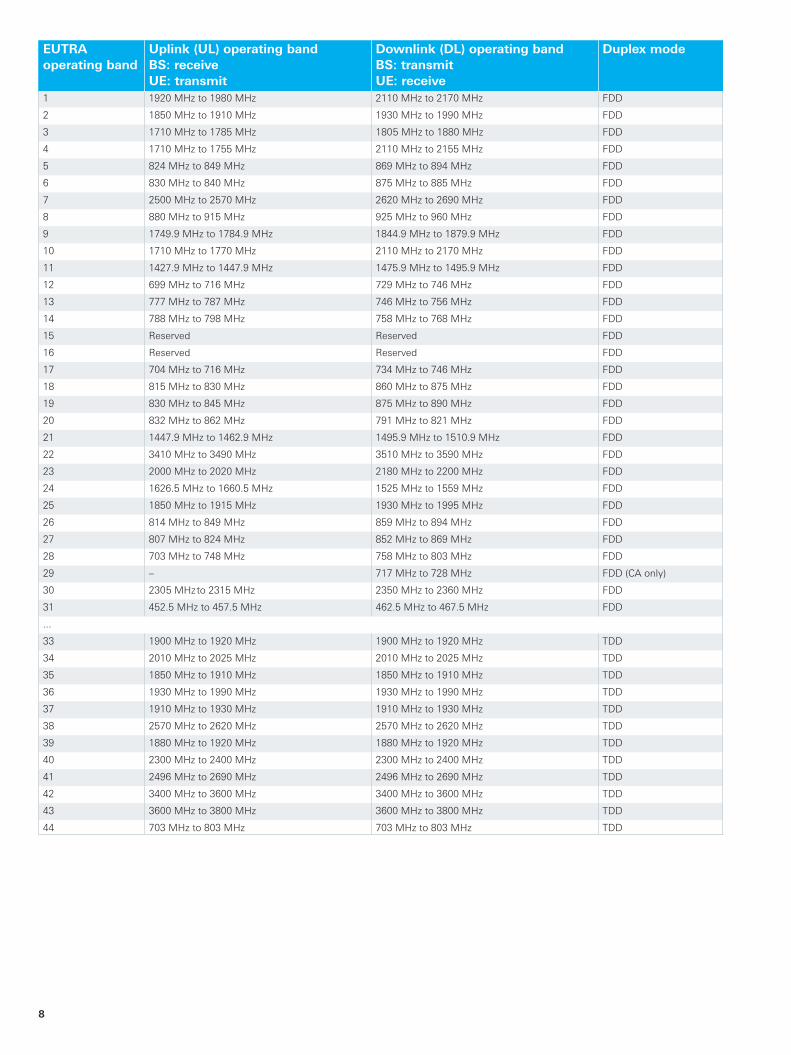
EUTRA operating band
Uplink (UL) operating bandBS: receiveUE: transmit
Downlink (DL) operating bandBS: transmitUE: receive
Duplex mode
1 1920 MHzto1980 MHz 2110 MHzto2170 MHz FDD
2 1850 MHzto1910 MHz 1930 MHzto1990 MHz FDD
3 1710 MHzto1785 MHz 1805 MHzto1880 MHz FDD
4 1710 MHzto1755 MHz 2110 MHzto2155 MHz FDD
5 824 MHzto849 MHz 869 MHzto894 MHz FDD
6 830 MHzto840 MHz 875 MHzto885 MHz FDD
7 2500 MHzto2570 MHz 2620 MHzto2690 MHz FDD
8 880 MHzto915 MHz 925 MHzto960 MHz FDD
9 1749.9 MHzto1784.9 MHz 1844.9 MHzto1879.9 MHz FDD
10 1710 MHzto1770 MHz 2110 MHzto2170 MHz FDD
11 1427.9 MHzto1447.9 MHz 1475.9 MHzto1495.9 MHz FDD
12 699 MHzto716 MHz 729 MHzto746 MHz FDD
13 777 MHzto787 MHz 746 MHzto756 MHz FDD
14 788 MHzto798 MHz 758 MHzto768 MHz FDD
15 Reserved Reserved FDD
16 Reserved Reserved FDD
17 704 MHzto716 MHz 734 MHzto746 MHz FDD
18 815 MHzto830 MHz 860 MHzto875 MHz FDD
19 830 MHzto845 MHz 875 MHzto890 MHz FDD
20 832 MHzto862 MHz 791 MHzto821 MHz FDD
21 1447.9 MHzto1462.9 MHz 1495.9 MHzto1510.9 MHz FDD
22 3410 MHzto3490 MHz 3510 MHzto3590 MHz FDD
23 2000 MHzto2020 MHz 2180 MHzto2200 MHz FDD
24 1626.5 MHzto1660.5 MHz 1525 MHzto1559 MHz FDD
25 1850 MHzto1915 MHz 1930 MHzto1995 MHz FDD
26 814 MHzto849 MHz 859 MHzto894 MHz FDD
27 807 MHzto824 MHz 852 MHzto869 MHz FDD
28 703 MHzto748 MHz 758 MHzto803 MHz FDD
29 – 717 MHzto728 MHz FDD(CAonly)
30 2305 MHzto2315 MHz 2350 MHzto2360 MHz FDD
31 452.5 MHzto457.5 MHz 462.5 MHzto467.5 MHz FDD
...
33 1900 MHzto1920 MHz 1900 MHzto1920 MHz TDD
34 2010 MHzto2025 MHz 2010 MHzto2025 MHz TDD
35 1850 MHzto1910 MHz 1850 MHzto1910 MHz TDD
36 1930 MHzto1990 MHz 1930 MHzto1990 MHz TDD
37 1910 MHzto1930 MHz 1910 MHzto1930 MHz TDD
38 2570 MHzto2620 MHz 2570 MHzto2620 MHz TDD
39 1880 MHzto1920 MHz 1880 MHzto1920 MHz TDD
40 2300 MHzto2400 MHz 2300 MHzto2400 MHz TDD
41 2496 MHzto2690 MHz 2496 MHzto2690 MHz TDD
42 3400 MHzto3600 MHz 3400 MHzto3600 MHz TDD
43 3600 MHzto3800 MHz 3600 MHzto3800 MHz TDD
44 703 MHzto803 MHz 703 MHzto803 MHz TDD
TSMW_bro_en_5213-9934-12.indd 8 24.06.2014 15:05:24

Typical drive test configuration
Test terminal R&S®ROMES software
Rohde & Schwarz R&S®TSMW Universal Radio Network Analyzer 9
All-in-one drive test solution with R&S®ROMES4
Technology Option3GPP LTE MIMO R&S®TSMWK30
3GPP LTE R&S®TSMWK29
WiMAX™IEEE802.16e R&S®TSMW-K28
GSM/WCDMA R&S®TSMW-K21
CDMA2000®,1xEV-DORev.B R&S®TSMWK22
TETRA R&S®TSMWK26
TETRARel.2(TEDS) R&S®TSMWK26Q
TETRA DMO R&S®TSMWK26D
RF power scan R&S®TSMW-K27
When combined with R&S®ROMES4, the R&S®TSMW can be used with
the technologies listed in the table.
When used together with the R&S®TSMW, the R&S®ROMES4 drive test software also supports test terminals. The R&S®TSMW can be used to detect and eliminate mobile radio network errors indicated by a terminal.
Network optimization with scanner and test terminal The R&S®ROMES4 drive test software not only evaluates measurement data from Rohde & Schwarz scanners, it also covers test terminals. These terminals establish either a voice or a data link. For example, a voice connection enablestheusertomeasurespeechqualityortogeneratea statistical evaluation about dropped calls. In the case of data links, the maximum possible transmission rate must be achieved. This is verified by means of data services such as an FTP download.
Improvement of QoSExample: LTEDuring an FTP download, a test terminal displays the maximum current data transmission rate. If this rate is too low with regard to the wireless communications technology beingused,thechannelqualityindicator(CQI)measuredby the test terminal can be used to trace the cause of the problem.
If the CQI is too low, either the received signal may be too weak or the measured SINR may be very low. In this case, the test terminal will not be able to use any higherorder modulation types such as 64QAM. The R&S®TSMW can detect and identify such trouble spots independently of the terminal. If the received signals are too weak, this may indicate that the test terminal did not find a neighbor cell. The R&S®TSMW is networkindependent because it does not rely on neighbor lists. Unknown neighbor cells can therefore be detected without any problem. Even automaticneighborrelation(ANR)algorithmsthatareusedbyself-organizingnetworks(SON)canbeverified.
TSMW_bro_en_5213-9934-12.indd 9 24.06.2014 15:05:24

10
Parallel support of multiple wireless communications technologies
The R&S®TSMW can be adapted to the customer's application by using various options. Together with the R&S®ROMES4 software, up to seven different technologies can be measured and displayed at the same time, while the hardware resources can be scaled as needed.
Simultaneous measurements in GSM, LTE, WCDMA, CDMA2000®, 1xEV-DO, TETRA and WiMAX™Multiple wireless communications technologies are often used simultaneously. Particularly during the rolloutoftechnologiessuchas3GPPLTEorWiMAX™IEEE802.16e,wirelesscommunicationsnetworkssuchasGSM/WCDMA,CDMA2000®,1xEV-DOorTETRAare already present. To keep the T & M effort and the related costs low, an allinone solution should be used. Rohde & Schwarz offers the perfect solution with its R&S®TSMW and the R&S®ROMES4 software.
Simple scanner setupTheusergenerallydoesnotrequireexpertknowledgeabout the wireless communications network to be tested. The R&S®TSMW detects all important information automatically. For example, the user only has to enter the following parameters: the UARFCN number in a WCDMA network,thebandinaGSMnetwork,thecenterfrequencyinaWiMAX™orLTEnetworkandthechannelnumberinaCDMA2000®,1xEV-DOnetwork.TheR&S®TSMWthenautomatically detects and measures all detectable scrambling codes, channels, preamble indices and physical cell IDs.Themeasurementspeedisnotaffectedbythequantity of measured signals. Similarly for TETRA, all active channelsina15 MHzdownlinkbandaredetectedand decoded automatically.
TSMW_bro_en_5213-9934-12.indd 10 24.06.2014 15:05:24

Rohde & Schwarz R&S®TSMW Universal Radio Network Analyzer 11
Flexible assignment of the two receivers for maximum measurement speedTechnologies to be measured can flexibly be distributed to two RF and signal paths. Measuring two techno logies in parallel does not cause any reduction in measurement speed. If further technologies are added, they are timedistributed to the hardware resources. This feature enables the R&S®TSMW to offer maximum performance in multipletechnology measurements. Up to seven wireless communications technologies can be measured at the same time.
Everything in one instrumentWireless communications scanners such as the R&S®TSMW are primarily used when measurements must be performed independently of a test terminal. The R&S®ROMES4 software offers a Top N evaluation of all available signals for each technology. The user receives an overview of the strongest signals and can sort them by provider. Especially in CDMA2000® and WCDMA networks, this evaluation plays a crucial role in reducing pilot pollution.
Furthermore, neighbor cells that may not be found by a test terminal can be detected. Missing neighbor cells can be detected independently of the technology. This enables the user to identify coverage gaps or interference. The capability to demodulate the broadcast information of the broadcastchannel(BCH)offersinsightintothenetworkconfiguration. Applications such as automatic neighborhood analysis or automatic interference detection can easily be carried out by applying this functionality.
The RF spectrum scan running in parallel additionally supports finding external interferences. Moreover, this function is very useful in spectrum clearing, in refarming and in using the digital dividend.
The R&S®TSMW can also be used for benchmark purposes. Multiple technologies and multiple providers can be scanned simultaneously. Even when a new technology is being rolled out, already present networks can be monitored as well.
Technologies supported by the R&S®TSMW
SIB decoding
GSM ● ●
WCDMA ● ●
CDMA2000® ● ●
1xEV-DO(Rel.0/Rev.A/Rev.B) ● ●
WiMAX™IEEE802.16e ● ●
TDLTE ● ●
LTE FDD ● ●
TETRA,TETRA 2,TETRADMO ● ●
TDSCDMA ● ●
TSMW_bro_en_5213-9934-12.indd 11 24.06.2014 15:05:24

12
Maximum flexibility when evaluating I/Q data
Seamless streaming of I/Q data in realtimeAspecialassetoftheR&S®TSMWisitsR&S®TSMW-K1digital I/Q data interface. Users of this option can, for example, perform technologyindependent channel measurements. These measurements can be used to simulate realistic fading scenarios in a lab environment. The recorded I/Q data can either be replayed in the lab using a Rohde & Schwarz signal generator or analyzed using the MATLAB®/C++ interface. I/Q data can be recorded in two ways. One, the R&S®TSMW can be connected with a PC via a LAN interface. Two, the data can be recorded with the R&S®IQR via the Rohde & Schwarz I/Q interface. The higher data rate of the Rohde & Schwarz I/Q interface makes it possible to record both frontends of the R&S®TSMWwithupto2×20 MHzinsteadofusinga20 MHzI/Qmeasurementbandwidth.
To facilitate I/Q data analysis, the GPS data is saved together with the I/Q data. The R&S®TSMW offers a truly mobile solution for recording all types of RF signals.
I/Q streaming via LAN (1)For this application, the R&S®TSMW and a highperformance PC are connected via Gigabit Ethernet. This interface allows a maximum streaming bandwidth of 20 MHzwith8/12/16or20-bitdatacompression.Themeasured data is stored on a fast hard disk. It can be replayed as a waveform on a Rohde & Schwarz signal generator or analyzed via MATLAB®. In addition to offering a MATLAB®based GUI for controlling the recording, the R&S®TSMW-K1optionalsoincludesaMATLAB®andaC++ interface.Theseinterfacespermitsimpleaccesstothe I/Q data after the measurement or in realtime. The recording time is limited only by the size of the hard disk. Aharddiskwithawritespeedofatleast80Mbyte/sisrecommended to avoid any problems.
I/Q streaming via Rohde & Schwarz I/Q interface (2)Due to its higher transmission bandwidth, the Rohde & Schwarz I/Q interface enables I/Q streaming with 2×20 MHzbandwidth.TheR&S®TSMWisdirectlyconnected with the R&S®IQR and is operated via the R&S®IQR touchscreen.
The I/Q data stored on the removable hard disks of the R&S®IQR can be output to a host PC via Gigabit Ethernet for offline analysis. All Rohde & Schwarz instruments with a Rohde & Schwarz I/Q interface, e.g. a signal generator, can be connected via the digital I/Q interface.
The R&S®IQR enables a recording time of one to three hoursdependingonthedigitalwordlength(8/12/16or20 bit).
TSMW_bro_en_5213-9934-12.indd 12 24.06.2014 15:05:24

Two ways to record I/Q data: I/Q data can be analyzed on a PC or replayed on a signal generator
1) Record I/Q data with up to 20 MHz bandwidth
¸TSMW PC
I/Q data
Gbit LAN I/Q interface
2) Record and replay I/Q data with 2 × 20 MHz bandwidth
R&S®TSMW with two RF frontends
Multiplexing of two I/Q data streamsR&S®IQR-K105
R&S®IQR
Export (offline)¸IQR-K101
2 ×
I/Q
USB
2.0
LAN
1 G
bit
I/Q data stream 1
I/Q data stream 2R&S®IQR-K107
Recording PlayingGeneratore.g. R&S®SMBV, R&S®SFC
PC, networkUSB storage
GPS(optional)
Rohde & Schwarz R&S®TSMW Universal Radio Network Analyzer 13
Equipment required for I/Q recording (1) ❙ R&S®TSMW universal radio network analyzer ❙ R&S®TSMW-K1digitalI/Qsoftwareoption ❙ R&S®TSMW-Z1ACpowersupply ❙ PCwithGigabitLANinterfaceandsupportofjumboframes
❙ HarddiskwithSATAinterfaceandmin.datawriterateof80Mbyte/s
Equipment required for I/Q recording (2) ❙ R&S®TSMW universal radio network analyzer ❙ R&S®TSMW-K1digitalI/Qsoftwareoption ❙ R&S®TSMW-B1Rohde&SchwarzI/Qinterface ❙ R&S®TSMW-Z1ACpowersupply ❙ R&S®IQR100I/Qdatarecorder ❙ R&S®IQR-B119Fmemorypack ❙ R&S®IQR-K1softwaretoconfigureR&S®TSMW
For additional options, see R&S®IQR brochure and datasheet.
The automatic gain control feature can be used to prevent RFleveloverdrivesandmaintaingoodsignalqualityincase of low signal strength. It is described in the R&S®IQR manual.TheR&S®IQR-K104optionisrequiredtousethisfeature.
Application examples ❙ Navigation: Recording of GPS/Glonass/Galileo/Compass (BeiDou)signalsindifferentregions.Recordedsignalscan be replayed under controlled conditions in the lab. This results in faster timetomarket for GPS receivers and mobile phones
❙ Broadcasting:RecordingofTV/FMsignalsduringadrive test. Recorded signals can be replayed under lab conditionstotestTV/FMreceivers
❙ LTE MIMO and LTEAdvanced: Channel measurements for4x2MIMOscenariosandsubsequentanalysis,e.g.using MATLAB®
TSMW_bro_en_5213-9934-12.indd 13 24.06.2014 15:05:26

Architecture of the dual-channel ¸TSMW universal radio network analyzer
Signal processing unit
Signal processing unit
Processor board
GbitPreselection and antenna switch
Frontend 1
Frontend 2
Power board GPS
DMA
GPS
14
Unsurpassed hardware platform performance and flexibility
Broadband with 20 MHz bandwidth and maximum frequency range from 30 MHz to 6 GHz The R&S®TSMW universal radio network analyzer offers a hardware platform with maximum flexibility. The two integratedbroadbandreceivers(30 MHzto6 GHz)withabandwidthof20 MHzeachandaseparatepreselectionopen the door to a variety of applications.
These features allow the R&S®TSMW to cover all existing andfuturefrequencybandswithoutanyadditionalup-grade costs.
Maximum configuration flexibilityThe R&S®TSMW contains two independent receivers withabandwidthof20 MHzeach.Thetworeceiverscan be used for different technologies or they can share the measurement tasks for a single technology, such as scanning and demodulating system information blocks (SIBs).Thiscaseisparticularlyinterestingwhenthemaxi-mum scan rate needs to be achieved. For LTE MIMOspecific measurements, the two receivers are controlled simultaneously.
Insomecases,onlyonereceiverisrequired,whichiswhy the R&S®TSMW is also available as a singlechannel model. A software option allows the second receiver to bequicklyandeasilyactivatedatalaterpointintime.Al-though it consumes 30 % less power, the singlechannel R&S®TSMW provides the full range of functions.
TSMW_bro_en_5213-9934-12.indd 14 24.06.2014 15:05:26

Rohde & Schwarz R&S®TSMW Universal Radio Network Analyzer 15
Integrated SuperSense GPS with PPSAnintegratedSuperSenseGPSreceiverwith50channelsandarefreshrateof4 Hzallowstheanalyzertoalsobeused in areas with weak GPS signals. The R&S®TSMW does not need a GPS signal to perform indoor measurements. GPS position fix can improve synchronization, but it is not absolutely necessary. The hardware also supports Glonass.
R&S®TSMF special solutionThe R&S®TSMF is a special model of the R&S®TSMW that does not permit any I/Q measurements with the R&S®TSMW-K1option.Allotherfunctionsarefully available.
Top dynamic range and measurement accuracy owing to adaptive preselectionTo achieve top measurement accuracy and dynamic range, the R&S®TSMW has an integrated preselection. Thus, multipleadjustablefiltersreduceintermodulationinadvance.The analyzer can therefore detect signals with a sensitivity that is considerably below the noise level (noise figure of 7 dBat3.5 GHz).
Update of hardware platform via softwareThe hardware platform can be updated and its functionality enhanced by means of software. This allows the R&S®TSMW to be expanded in the field to handle additional technologies without having to be sent in for an upgrade.Onlythespecificoptionsrequiredareadded,forexample when the user wants to add LTE or LTE MIMO to the existing GSM/WCDMA function.
TSMW_bro_en_5213-9934-12.indd 15 24.06.2014 15:05:27

16
Supported by many drive test tools
The R&S®TSMW universal radio retwork analyzer is supported by a multitude of professional drive test tools, and can be used by any specialized measurement software. UsingtheopenViCominterface,developerscaneasilyintegrate the R&S®TSMW and other R&S®TSMx scanner family members into their own coverage measurement software applications as an OEM receiver.
Open interfaces for integration into individual software solutionsTheViComAPIprovidesfullaccesstoGSM,WCDMA,LTE(FDD/TDD),TD-SCDMA,CDMA2000®,1xEV-DOandWiMAXTM measurements as well as the scanner’s L3 decoding results. The RF power scan capability of the R&S®TSMW and the data from the builtin GPS module can also be used.
See www.rohdeschwarz.com forViCominterfacedescription.
Flexibility in choice of drive test softwareThe listed commercially available software tools support the R&S®TSMW.
Software product Supported functionality
R&S®ROMESNetwork Problem Analyzer
GSM,WCDMA,LTE(FDD/TDD),LTEMIMO,CDMA2000®,1xEV-DO,WiMAXTM, RF power scan
Diversity OptimizerDiversity Benchmarker
GSM,WCDMA,LTE(FDD/TDD),LTEMIMO,CDMA2000®,1xEV-DO,RFpowerscan
XCALXCAP
WCDMA,CDMA2000®,1xEV-DO,LTE(FDD/TDD)
Nemo OutdoorNemo Invex
GSM,WCDMA,LTE(FDD/TDD),LTEMIMO,CDMA2000®,1xEV-DO,RFpowerscan
TEMS Investigation GSM,WCDMA,LTE(FDD/TDD),LTEMIMO,CDMA2000®,1xEV-DO
Pilot PioneerPilot Navigator
GSM,WCDMA,LTE(FDD/TDD),CDMA2000®,1xEV-DO,RF powerscan
TSMW_bro_en_5213-9934-12.indd 16 24.06.2014 15:05:27

Rohde & Schwarz R&S®TSMW Universal Radio Network Analyzer 17
SpecificationsSpecificationsRF characteristics
Frequencyrange 30 MHzto6 GHz
Level measurement uncertainty S/N>16 dB,30 MHzto3 GHz <1 dB
S/N>16 dB,3 GHzto6 GHz <1.5 dB
Maximum permissible input level 5 dBm/0 VDC
Noise figure900 MHz,2100 MHz,3500 MHz,6000 MHz
typical with preamplifier on6 dB,8 dB,7 dB,10 dB
Intermodulationfree dynamic range level2×–45 dBm,3.5 GHz,preamplifieron –65 dBc(typ.)(–12.5 dBmTOI)
level2×–35 dBm,3.5 GHz,preamplifieroff 70 dBc(typ.)(0 dBmTOI)
RF receive paths independent 2
VSWR 30 MHz≤f≤2.5 GHz 1.5(typ.)
2.5 GHz≤f≤6 GHz 1.7(typ.)
Preselection channels 5perRFpath,3usedastrackingfilters
LTE characteristics
Frequencybandssupported automatic detection of carrier bandwidth no restrictions
Measurement modes LTEFDD and TDLTE
Measurement speed automaticdetectionofall504physicalcellIDswith SIB decoding active
max. 200 measurements/s
Physical decoding accuracy
Sensitivity for initial physical cell ID decoding SYNC signal powerSYNC signal RE power
–123 dBm –140.9 dBm
Sensitivity after successful physical cell ID decoding
SYNC signal powerSYNC signal RE power
–127 dBm –144.9 dBm
RS SINR dynamic range –20 dBto+42 dB
SYNC SINR dynamic range –20 dBto+42 dB
PCIfalsedetection(ghostcode) <10–8
WiMAX™ characteristics
Frequencybandssupported no restrictions
Measurement speed automaticdetectionofall114preambleindices 5measurements/s
Preamble decoding accuracy frameduration5 ms,FFTsize1024,10 MHzbandwidth,2.5 GHz
±1 dB(–30 dBmto–109 dBm)
Sensitivity for initial preamble decoding RSSI <–97 dBm
Sensitivity after successful preamble decoding RSSI <–112 dBm
SINR 1) dynamic range –20 dBto+26 dB
GSM characteristics
Frequencybandssupported no restrictions
Measurement modes in parallel DB/TCH/SCHcodepower,TCHtotalin-bandpower, timeslot power, GSM spectrum, BCH demodulationforallsysteminformationtypes
Measurement speed with SI decoding active 500channels/s
Sensitivity –118 dBm
Measurement accuracy ±1 dB(typ.)
BSIC decoding accuracy 98%forC/I>+2 dB
BSIC decoding dynamic range
Sensitivity for initial BSIC detection C/I>–2 dB
Sensitivity after successful BSIC detection C/I>–11 dB
BCCHdecodingdynamicrange C/I>0 dB
1) Derived measurement value.
TSMW_bro_en_5213-9934-12.indd 17 24.06.2014 15:05:28

18
SpecificationsWCDMA characteristics
Frequencybandssupported no restrictions
NumberofRFcarrierfrequencies max. 32
Measurement speed high speed/high dynamic rangeautomaticdetectionofall512scramblingcodes
200 Hz/12 Hz,withBCHdemodulation
Scramblingcodedetectionsensitivity(RSCP)
Sensitivity for initial SC detection high speed/high dynamic range –112 dBm/–121 dBm
Sensitivity after successful SC detection high speed/high dynamic range –118 dBm/–123 dBm
Scramblingcodedetectionaccuracy(RSCP) Ec/I0>–12 dB <1 dB(typ.)
Ec/I0<–12 dB <1.5 dB(typ.)
Scramblingcodefalsedetection(ghostcode) <10–9
Dynamic range Ec/I0 high speed/high dynamic range –22 dB/–30 dB
Min.BCHdemodulationthresholdEc/I0 >–17 dB
TD-SCDMA characteristics
Frequencybandssupported no restrictions
NumberofRFcarrierfrequencies max. 32
Measurement speed high speed, high sensitivity
20 Hz,withBCHdemodulation, 8 Hz,withBCHdemodulation
Automaticdetectionofall128scramblingcodes
Scrambling code detection sensitivity
SensitivityforinitialBTSdetection(DwPTS) high speed/high sensitivity –114 dBm/–113 dBm
SensitivityforinitialSCdetection(midamble) high speed/high sensitivity –115 dBm/–114 dBm
Sensitivity after successful BTS detection high speed/high sensitivity –115 dBm/–117 dBm
Scrambling code detection accuracy RSCP typ.<1 dB
Dynamic range Ec/I0(DwPTSinitialdetection) high speed, high sensitivity
–7 dB, –7 dB
CDMA2000® characteristics
Frequencybandssupported no restrictions
NumberofRFcarrierfrequencies max. 32
Measurement speed automaticdetectionofall512PNcodes 80 Hz,withBCHdemodulation
PN detection sensitivity –119 dBm
Dynamic range Ec/I0 –29 dB
1xEV-DO characteristics (Rel.0/Rev.A/Rev.B)
Frequencybandssupported no restrictions
NumberofRFcarrierfrequencies max. 32
Measurement speed 30 Hz,withBCHdemodulation
PN detection sensitivity –120 dBm
Dynamic range Ec/I0 –15 dB
TETRA characteristics
TETRA bands supported no restrictions
NumberofRFcarrierfrequencies withina10 MHzdownlinkband max. 400
Channel resolution 25 kHz(QPSK)
Measurement speed max.8000channels/s,20/sfora10 MHzblock
Sensitivity(RSSI) RSSI measurements –126 dBm
TETRABSCHdecoding(BSCHdecodingforchannelswithanSNR>9.5 dB)
–120 dBm
BER measurements –126 dBm
TSMW_bro_en_5213-9934-12.indd 18 24.06.2014 15:05:28

Rohde & Schwarz R&S®TSMW Universal Radio Network Analyzer 19
SpecificationsTETRA2 (TEDS) characteristics
TETRA bands supported no restrictions
NumberofRFcarrierfrequencies withina10 MHzband max. 400
Channel resolution 25 kHz(QAM)
Channel bandwidths autodetection 25 kHz,50 kHz,100 kHz,150 kHz
Code rates autodetection 1/2,2/3,1
Modulation autodetect 4QAM,16QAM,64QAM
Sensitivity RSSI measurements –120 dBm(for25 kHzchannelbandwidth)
TETRABSCHdecoding(BSCHdecodingforchannelswithanSNR>9.5 dB)
–115 dBm
BER measurements4QAM, code rate 2/3, 4QAM,coderate1/2, 16QAM,coderate1/2, 16QAM,coderate2/3, 64QAM,coderate1/2, 64QAM, code rate 2/3
–115 dBm, 4QAMcoderate2/3–1.8 dB, 4QAMcoderate2/3+4 dB, 4QAMcoderate2/3+6.1 dB, 4QAMcoderate2/3+8.5 dB, 4QAMcoderate2/3+11.4 dB
Measurement speed max.8000channels/s,20/sfora10 MHzblock
I/Q characteristics (requires R&S®TSMW-K1)
Digital filter bandwidth, burst 800 kHzto20 MHz
Digital filter bandwidth, streaming hardwarerequirements:GbitLANlink,jumboframes,harddisktransferrate80 Mbyte/s
max. 22 Msample/s
Resampling rate 1Msample/sto23Msample/s
Demodulation bandwidth 20 MHz
I/Q buffer size 200 Mbyte
Software support R&S®ROMES4drivetestsoftwarenotrequired;MATLAB® or customerspecific software must be installed
Gbit LAN I/Q interface
Data format 14-bitADCresolution 8/12/16bitor20bit
Digital I/Q interface (additionally requires R&S®TSMW-B1) 2)
Interface direction output
level LVDS
connector 26pin MDR
Standard protocol sample rate up to 23 Msample/supto2×23Msample/s(multiplexmode)
resolution 20 bit for I and Q, 18bitforIandQ(multiplexmode)
general purpose signals unused
Transfer mode enable mode supported
Channel multiplex transmission of several I/Q data streams in time division multiplex
upto8channels
Source interfacemode1(enablemode) frontend1and2
Automaticgaincontrol(AGC) requiresR&S®IQRwithR&S®IQR-K1andR&S®IQR-K104
target signal range –30 dBmto–60 dBm
adjustmentsteps ±4 dB
RF power scan
Frequencyrange 30 MHzto6 GHz
Frequencyresolution 140 Hzto1.438 MHz
Sensitivity 22.4 kHzRBW,RMS,at900 MHz
preamplifier off –112 dBm
preamplifier on –121 dBm
140 HzRBW,RMS,at900 MHz
preamplifier off –134 dBm
preamplifier on –141 dBm
2) Suitable cable included with R&S®IQR I/Q data recorder.
TSMW_bro_en_5213-9934-12.indd 19 24.06.2014 15:05:28

20
SpecificationsScan speed 180 kHzresolution,100 MHzspan,
20 MHzbandwidth130 Hz
11.23 kHzresolution,10 MHzspan, 10 MHzbandwidth
690 Hz
140 Hzresolution,1 MHzspan, 1 MHzbandwidth
64 Hz
RSSI scan speed 20 MHzspan,20 MHzbandwidth 99GSMchannels:600 Hz(59400channels/s)
20 MHzspan,20 MHzbandwidth 4WCDMAchannels:600 Hz(2400channels/s)
20 MHzspan,20 MHzbandwidth 1LTEchannel(100RB):600 Hz(600channels/s)
Max.numberoffrequencyranges 20
Detectors max., min., RMS, auto
Reference frequency
Aging 1×10⁻⁶ aging per year
Output for internal reference signal frequency(approx.sinewave) 10 MHz
level 0 dBm(typ.)
source impedance 50 Ω
Input for external reference signal frequency 10 MHz
max.deviation 3×10⁻⁶
input level limits >–6 dBm,<19 dBm
recommended 0 dBmto19 dBm
input impedance 50 Ω
Physical characteristics
RF inputs SnapN connector 50 Ω
Data interface RJ-45 10/100/1000BaseTEthernet3)
Reference input/output BNC female 50 Ω
Pulse input/output 2 × BNC female 5 V,TTL
GPS antenna SMA female/active GPS antenna 50 Ω/3 V,max.100 mA
GPSUSBinterface(standalone) type B USB connector
GPS receiver
Sensitivity cold start, tracking
–148 dBm,–162 dBm
Acquisition cold start, hot start
26 s,<1 s
Channels 50
System requirements controller(PentiumIV,2GbyteRAM,GigabitEthernet(jumbopacketsofatleast4 kbyte, flowcontrolenabled),USB1.0,USBrequiredonlyifGPSisusedasstandaloneapplication)
3) JumboframesarerecommendedformeasurementswithR&S®TSMW-K1.AllmeasurementspeedspecificationscanvarydependingonthespeedofthePCused.
TSMW_bro_en_5213-9934-12.indd 20 24.06.2014 15:05:28

Rohde & Schwarz R&S®TSMW Universal Radio Network Analyzer 21
General dataEnvironmental conditions
Temperature operating temperature range +5°Cto+40°C
permissible temperature range 0°Cto+50°C
storage temperature range –25°Cto+85°C
Damp heat +40°C,95%,relativehumidity,cyclic inlinewithEN60068-2-30
Mechanical resistance
Vibration sinusoidal 5 Hzto55 Hz,0.15 mmconstantamplitude, 55 Hzto150 Hz,0.5gconstantinlinewithEN60068-2-6
random 10 Hzto300 Hz,acceleration1.2gRMSinlinewithEN60068-2-64
Shock 40 g shock spectrumMIL-STD-810E,methodno.516.4,procedureI
Power rating
Rated voltage 9 Vto18 VDC
Rated current max.10 A
usewithR&S®TSMW-Z1externalpowersupply 100 Vto240 VAC,47 Hzto63 Hz,2.5 A
Dimensions W×H×D 180 mm×130 mm×270 mm(7.1in×5.12in×10.63in)
Weight approx.5.1 kg(11.26lb)
Product conformity
Electromagnetic compatibility EU inlinewithEMCdirective2004/108/ECand72/245/EEC applied harmonized standard:EN61326-1(industrialenvironment), EN61326-2-1,EN55011(classB),EN61000-3-2,EN61000-3-3,72/245/EECchapter3.2.9applied
Electrical safety EU inlinewithLowVoltageDirective2006/95/EC applied harmonized standardEN61010-1
Korea KC mark
USA UL61010-1
Canada CAN/CSAC22.2No.61010.1-04
International safety approvals VDE–AssociationforElectrical,ElectronicandInformation Technologies
VDE-GSmark,certificateno.40023750
CSA – Canadian Standards Association cCSAusmark,certificateno.1986837
TSMW_bro_en_5213-9934-12.indd 21 24.06.2014 15:05:28

22
Ordering informationDesignation Type Order No.Base unit
Universal Radio Network Analyzer(scopeofdelivery:R&S®TSMW,LANcable,2×antennas(820 MHzto960 MHz,1700 MHzto2170 MHz),GPSantenna,12 VDCpowercable (cigarettelighterconnector),CD)
R&S®TSMW 1503.3001.03
Universal Radio Network Analyzer, without I/Q streaming capabilities R&S®TSMF 1503.3001.04
R&S®TSMW options
TDSCDMA Scanner Option R&S®TSMWK20 1515.7320.02
GSM/WCDMA Scanner Option R&S®TSMW-K21 1503.4514.02
CDMA2000®,1xEV-DORev.AScannerOption R&S®TSMWK22 1503.4520.02
TETRAScannerOption(forR&S®ROMES4) R&S®TSMWK26 1510.8792.02
TETRARel.2(TEDS)ScannerOption(forR&S®ROMES4) R&S®TSMWK26Q 1510.8792.03
TETRADMOScannerOption(forR&S®ROMES4) R&S®TSMWK26D 1510.8792.04
RF Power Scanner Option R&S®TSMW-K27 1503.4537.02
WiMAX™ScannerOption R&S®TSMW-K28 1503.4543.02
LTE Scanner Option R&S®TSMWK29 1503.4550.02
LTE MIMO Scanner Option R&S®TSMWK30 1514.4085.02
LTE DL Allocation Analyzer Scanner Option R&S®TSMW-K31 3590.6813.02
Gigabit LAN I/Q Interface R&S®TSMW-K1 1503.3960.02
R&S®DigitalI/QInterface(hardwareoption) R&S®TSMW-B1 1514.4004.02
Single Receiver Option R&S®TSMW-K71 1514.4027.02
Software options
R&S®TSMW Scanner Driver for R&S®ROMES4 Drive Test Software R&S®ROMES4T1W 1117.6885.02
Additional software
Drive Test Software R&S®ROMES4 1117.6885.04
R&S®TSMW Driver for R&S®ROMES4 Drive Test Software R&S®ROMES4T1W 1117.6885.02
R&S®ROMES4 Option, Base Station Position Estimation R&S®ROMES4LOC 1117.6885.32
R&S®ROMES4 Driver, Automatic Channel Detection R&S®ROMES4ACD 1506.9869.02
System components
Power Supply R&S®TSMW-Z1 1503.4608.02
19"RackAdapter R&S®TSMWZ2 1503.3901.02
Backpack System R&S®TSMWZ3N 1514.4091.02
Battery for Backpack System R&S®TSME-Z3B1 1519.0913.02
DualCharger for Backpack System R&S®TSMEZ3BC2 1519.0920.02
Transit Case with Rollers R&S®TSMW-Z5 1117.9955.02
Soft Carrying Bag R&S®HA-Z220 1309.6175.00
Portable System Suitcase R&S®TS51GA30 1090.7993.12
Magnetic Antenna Mount without GPS R&S®TSMW-ZA1 1145.6705.00
Fixed Antenna Mount without GPS R&S®TSMWZA2 1145.6711.00
Magnetic Antenna Mount with GPS R&S®TSMWZA3 1145.6728.00
Fixed Antenna Mount with GPS R&S®TSMWZA4 1145.6734.00
Antenna,400 MHzto440 MHz(requiresantennamount) R&S®TSMWZE2 1117.8165.00
Antenna,360 MHzto410 MHz(requiresantennamount) R&S®TSMWZE3 1117.8159.00
Antenna,698 MHzto2700 MHz(requiresantennamount) R&S®TSMW-ZE8 1506.9852.02
MIMOAntenna,700 MHz R&S®TSMW-Z7 1518.1845.02
MIMO Antenna, Multiband R&S®TSMW-Z8 1518.1851.02
GPS RF Recording Kit for the R&S®TSMW R&S®TSMWZ20 1506.9775.02
TSMW_bro_en_5213-9934-12.indd 22 24.06.2014 15:05:28

Rohde & Schwarz R&S®TSMW Universal Radio Network Analyzer 23
Service optionsExtended Warranty, one year R&S®WE1 Please contact your local
Rohde & Schwarz sales office.Extended Warranty, two years R&S®WE2
Extended Warranty, three years R&S®WE3
Extended Warranty, four years R&S®WE4
Extended Warranty with Calibration Coverage, one year R&S®CW1
Extended Warranty with Calibration Coverage, two years R&S®CW2
Extended Warranty with Calibration Coverage, three years R&S®CW3
Extended Warranty with Calibration Coverage, four years R&S®CW4
YourlocalRohde&Schwarzexpertwillhelpyoudeterminetheoptimumsolutionforyourrequirements.To find your nearest Rohde & Schwarz representative, visit www.sales.rohdeschwarz.com
CDMA2000®isaregisteredtrademarkoftheTelecommunicationsIndustryAssociation(TIA-USA).WiMAXForumisaregisteredtrademarkoftheWiMAXForum.WiMAX,theWiMAXForumlogo,WiMAXForumCertified,andtheWiMAXForumCertifiedlogoaretrademarksoftheWiMAXForum.
TSMW_bro_en_5213-9934-12.indd 23 24.06.2014 15:05:28

R&S®isaregisteredtrademarkofRohde&SchwarzGmbH&Co.KG
Trade names are trademarks of the owners
PD5213.9934.12|Version10.00|June2014(as)
R&S®TSMW Universal Radio Network Analyzer
Datawithouttolerancelimitsisnotbinding|Subjecttochange
©2009-2014Rohde&SchwarzGmbH&Co.KG|81671Munich,Germany
Service that adds value❙ Worldwide ❙ Local and personalized❙ Customized and flexible❙ Uncompromising quality ❙ Long-term dependability
5213.9934.1210.00PDP1en
About Rohde & SchwarzThe Rohde & Schwarz electronics group is a leading supplier of solutions in the fields of test and measurement, broadcasting, secure communications, and radiomonitoring and radiolocation. Founded more than 80 years ago, this independent global company has an extensive sales network and is present in more than 70 countries. The company is headquartered in Munich, Germany.
Regional contact ❙ Europe, Africa, Middle East | +49 89 4129 12345 customersupport@rohdeschwarz.com
❙ North America | 1 888 TEST RSA (1 888 837 87 72) [email protected]schwarz.com
❙ Latin America | +1 410 910 79 88 customersupport.la@rohdeschwarz.com
❙ Asia/Pacific | +65 65 13 04 88 customersupport.asia@rohdeschwarz.com
❙ China | +86 800 810 8228/+86 400 650 5896 customersupport.china@rohdeschwarz.com
Rohde & Schwarz GmbH & Co. KGwww.rohdeschwarz.com
Sustainable product design ❙ Environmental compatibility and ecofootprint ❙ Energy efficiency and low emissions ❙ Longevity and optimized total cost of ownership
Certified Environmental Management
ISO 14001Certified Quality Management
ISO 9001
5213993412
TSMW_bro_en_5213-9934-12.indd 24 24.06.2014 15:05:28