Embed Size (px)
Citation preview
4 www.hapco.comProven Performance
Handhole
B Wall Thickness Round Straight Steel TubeASTM A500 Grade B Steel
Handhole
4-Bolt BaseWith Cover
C Butt Diameter
A M
ount
ing
Heig
ht
D Top Diameter1'
-6"
Removable Pole Cap (Tenon Option Available)
Dimensions in Inches
C D F G H I Butt Dia. top Dia. Bolt Cir. Dia. Base sq. Bolt proj. Bolt size 3 3 7.5-8.5 8 3.75 .75 x 17 x 3 4 4 7.5-8.5 8 3.75 .75 x 17 x 3 4.5 4.5 7.5-8.5 8 3.75 .75 x 17 x 3 5 (11 Gauge) 5 7.5-8.5 8 3.75 .75 x 17 x 3 5 (7 Gauge) 5 8-9 8.75 4.875 1 x 36 x 4
Pole shaft shall be weldable-grade, cold-rolled, commercial quality carbon steel tubing conforming to ASTM A500 Grade B. Options include 11 gauge and 7 gauge. All welds shall conform to AWS D1.1 using ER70S-6 electrodes.
Pole
Anchorage
Vibration Damper
Base Style
Base Cover
Anchorage Kit will include four (4) L-shaped Steel Anchor Bolts conforming to AASHTO M314-90 Grade 55. Ten inches (10”) of threaded end will be galvanized per ASTM A153. Kits will contain eight (8) Hex Nuts, four (4) Lock Washers, and eight (8) Flat Washers (all components Galvanized Steel). A paper bolt circle template will be provided.
IIf determined necessary by Hapco, or if specified by the customer, a first and/or second mode vibration damper will be provided.
Round Straight Steel PoleNo Arm — 4-Bolt BaseRSS
Powder Coated, Galvanized or Powder Coated over Galvanized Finish Per Customer Specification.
WARNING: Do not install light pole without luminaire.
Handhole - 0°
180°|
I
0°
- 90° 270° -
GBase
Square
FBolt
Circle
H Bolt Proj. IBoltSize
3" Butt Diameter - Reinforced, 2" x 4" Handhole with cover and stainless steel screws. A grounding provision incorporating a tapped 1/2"-13NC hole will be provided.
4"+ Butt Diameters -Reinforced, 3" x 5" Handhole with cover, stainless steel screw and backbar. A grounding provision incorporating a tapped 1/2"-13NC hole will be provided.
4-Bolt Steel Base Plate of fabricated hot rolled carbon steel conforming to ASTM A36 or equivalent (36 ksi minimum yield) with 2-piece Base Cover and attaching hardware.
Round ABS plastic Base Covers are standard in all 11 Gauge RSS poles specified in powder coat finishes BA-Black, BM-Dark Bronze and BH-White. Square metal powder coated Base Covers are standard in all 11 Gauge RSS poles that are specified in colors other than BA, BM, and BH and in all 7 Gauge poles in ALL COLORS. Custom specification of RSS Square Metal style Base Covers in BA, BM and BH powder coated finishes is available.
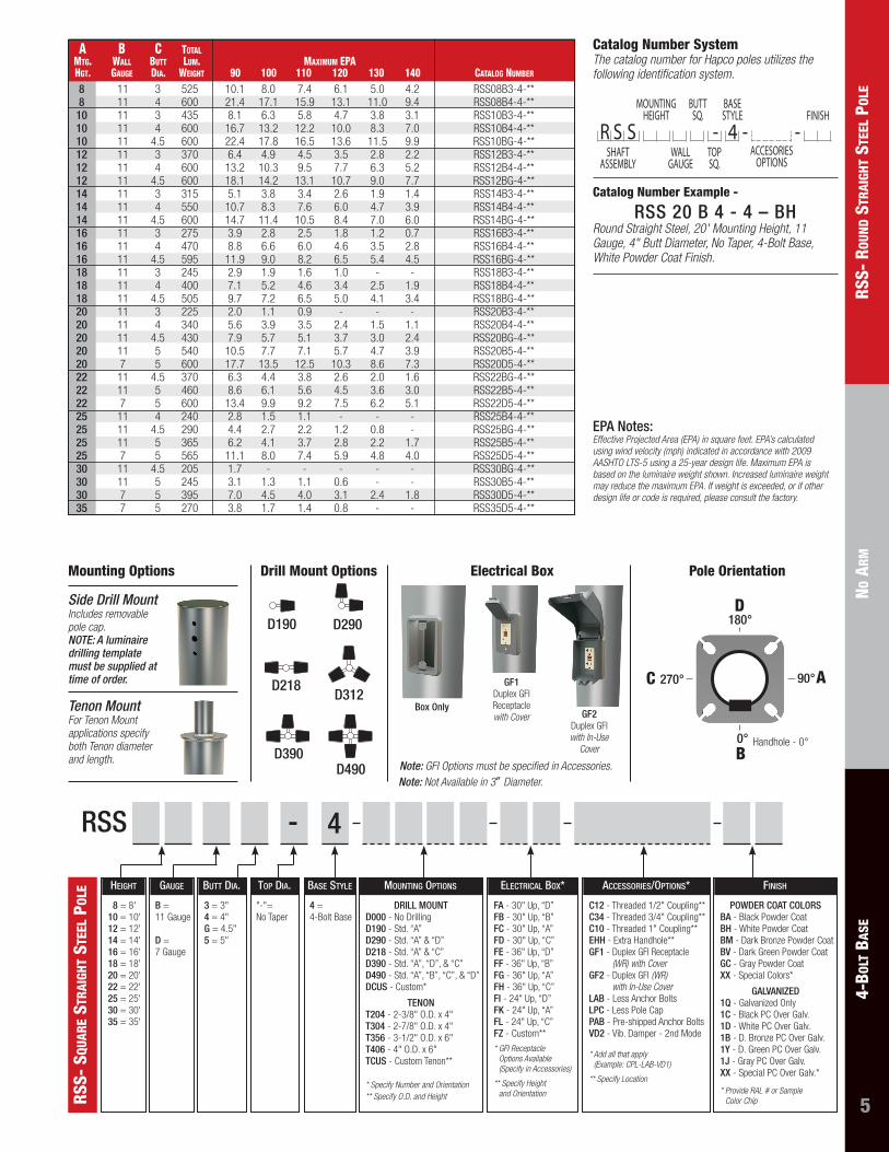
5
rss-
rou
nD s
trai
ght
stee
l po
leno
arm
4-Bo
lt B
ase
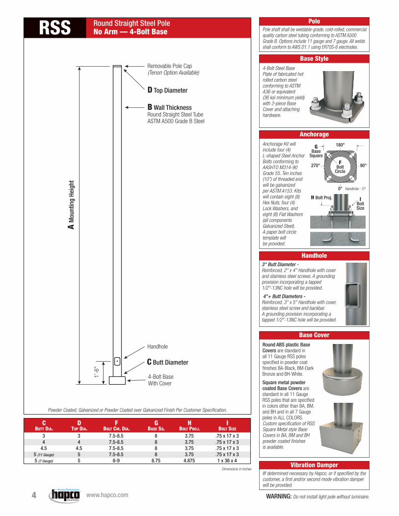
EPA Notes: Effective Projected Area (EPA) in square feet. EPA’s calculated using wind velocity (mph) indicated in accordance with 2009 AASHTO LTS-5 using a 25-year design life. Maximum EPA is based on the luminaire weight shown. Increased luminaire weight may reduce the maximum EPA. If weight is exceeded, or if other design life or code is required, please consult the factory.
a B C total mtg. Wall Butt lum. maximum epa hgt. gauge Dia. Weight 90 100 110 120 130 140 Catalog numBer
11 3 525 10.1 8.0 7.4 6.1 5.0 4.2 RSS08B3-4-** 11 4 600 21.4 17.1 15.9 13.1 11.0 9.4 RSS08B4-4-** 11 3 435 8.1 6.3 5.8 4.7 3.8 3.1 RSS10B3-4-** 11 4 600 16.7 13.2 12.2 10.0 8.3 7.0 RSS10B4-4-** 11 4.5 600 22.4 17.8 16.5 13.6 11.5 9.9 RSS10BG-4-** 11 3 370 6.4 4.9 4.5 3.5 2.8 2.2 RSS12B3-4-** 11 4 600 13.2 10.3 9.5 7.7 6.3 5.2 RSS12B4-4-** 11 4.5 600 18.1 14.2 13.1 10.7 9.0 7.7 RSS12BG-4-** 11 3 315 5.1 3.8 3.4 2.6 1.9 1.4 RSS14B3-4-** 11 4 550 10.7 8.3 7.6 6.0 4.7 3.9 RSS14B4-4-** 11 4.5 600 14.7 11.4 10.5 8.4 7.0 6.0 RSS14BG-4-** 11 3 275 3.9 2.8 2.5 1.8 1.2 0.7 RSS16B3-4-** 11 4 470 8.8 6.6 6.0 4.6 3.5 2.8 RSS16B4-4-** 11 4.5 595 11.9 9.0 8.2 6.5 5.4 4.5 RSS16BG-4-** 11 3 245 2.9 1.9 1.6 1.0 - - RSS18B3-4-** 11 4 400 7.1 5.2 4.6 3.4 2.5 1.9 RSS18B4-4-** 11 4.5 505 9.7 7.2 6.5 5.0 4.1 3.4 RSS18BG-4-** 11 3 225 2.0 1.1 0.9 - - - RSS20B3-4-** 11 4 340 5.6 3.9 3.5 2.4 1.5 1.1 RSS20B4-4-** 11 4.5 430 7.9 5.7 5.1 3.7 3.0 2.4 RSS20BG-4-** 11 5 540 10.5 7.7 7.1 5.7 4.7 3.9 RSS20B5-4-** 7 5 600 17.7 13.5 12.5 10.3 8.6 7.3 RSS20D5-4-** 11 4.5 370 6.3 4.4 3.8 2.6 2.0 1.6 RSS22BG-4-** 11 5 460 8.6 6.1 5.6 4.5 3.6 3.0 RSS22B5-4-** 7 5 600 13.4 9.9 9.2 7.5 6.2 5.1 RSS22D5-4-** 11 4 240 2.8 1.5 1.1 - - - RSS25B4-4-** 11 4.5 290 4.4 2.7 2.2 1.2 0.8 - RSS25BG-4-** 11 5 365 6.2 4.1 3.7 2.8 2.2 1.7 RSS25B5-4-** 7 5 565 11.1 8.0 7.4 5.9 4.8 4.0 RSS25D5-4-** 11 4.5 205 1.7 - - - - - RSS30BG-4-** 11 5 245 3.1 1.3 1.1 0.6 - - RSS30B5-4-** 7 5 395 7.0 4.5 4.0 3.1 2.4 1.8 RSS30D5-4-** 7 5 270 3.8 1.7 1.4 0.8 - - RSS35D5-4-**
88
10101012121214141416161618181820202020202222222525252530303035
Handhole - 0°
180°
0°
90° 270°
D
AC
B
R S S - 4 - -MOUNTING
HEIGHT
WALLGAUGE
SHAFTASSEMBLY
BUTTSQ.
TOPSQ.
BASESTYLE FINISH
ACCESORIESOPTIONS
Catalog Number System The catalog number for Hapco poles utilizes the following identification system.
Catalog Number Example -
RSS 20 B 4 - 4 – BHRound Straight Steel, 20' Mounting Height, 11 Gauge, 4" Butt Diameter, No Taper, 4-Bolt Base, White Powder Coat Finish.
Tenon MountFor Tenon Mount applications specify both Tenon diameter and length.
Side Drill MountIncludes removable pole cap. NOTE: A luminaire drilling template must be supplied at time of order.
Mounting Options Pole Orientation
D490
D312
D390
D190 D290
D218
Drill Mount Options
Note: GFI Options must be specified in Accessories. Note: Not Available in 3″ Diameter.
Box Only
GF1Duplex GFI Receptacle with Cover GF2
Duplex GFI with In-Use
Cover
Electrical Box
8 = 8' 10 = 10' 12 = 12' 14 = 14' 16 = 16' 18 = 18' 20 = 20' 22 = 22' 25 = 25' 30 = 30' 35 = 35'
3 = 3" 4 = 4" G = 4.5" 5 = 5"
"-"= No Taper
4 = 4-Bolt Base
DRILL MOUNT D000 - No Drilling D190 - Std. “A” D290 - Std. “A” & “D” D218 - Std. “A” & “C” D390 - Std. “A”, “D”, & “C” D490 - Std. “A”, “B”, “C”, & “D” DCUS - Custom*
TENON T204 - 2-3/8" O.D. x 4" T304 - 2-7/8" O.D. x 4" T356 - 3-1/2" O.D. x 6" T406 - 4" O.D. x 6" TCUS - Custom Tenon**
* Specify Number and Orientation ** Specify O.D. and Height
FA - 30" Up, “D” FB - 30" Up, “B” FC - 30" Up, “A” FD - 30" Up, “C” FE - 36" Up, “D” FF - 36" Up, “B” FG - 36" Up, “A” FH - 36" Up, “C” FI - 24" Up, “D” FK - 24" Up, “A” FL - 24" Up, “C” FZ - Custom**
* GFI Receptacle Options Available (Specify in Accessories)
* * Specify Height and Orientation
C12 - Threaded 1/2" Coupling** C34 - Threaded 3/4" Coupling** C10 - Threaded 1" Coupling** EHH - Extra Handhole** GF1 - Duplex GFI Receptacle
(WR) with Cover GF2 - Duplex GFI (WR)
with In-Use Cover LAB - Less Anchor Bolts LPC - Less Pole Cap PAB - Pre-shipped Anchor Bolts VD2 - Vib. Damper - 2nd Mode * Add all that apply
(Example: CPL-LAB-VD1)
** Specify Location
B = 11 Gauge
D = 7 Gauge
HeigHt Butt Dia. top Dia. Base style Mounting options electrical Box* accessories/options*gauge
rss-
squ
are
stra
ight
ste
el p
ole
RSS - 4
POWDER COAT COLORS BA - Black Powder Coat BH - White Powder Coat BM - Dark Bronze Powder Coat BV - Dark Green Powder Coat GC - Gray Powder Coat XX - Special Colors*
GALVANIZED 1Q - Galvanized Only 1C - Black PC Over Galv. 1D - White PC Over Galv. 1B - D. Bronze PC Over Galv. 1Y - D. Green PC Over Galv. 1J - Gray PC Over Galv. XX - Special PC Over Galv.*
* Provide RAL # or Sample Color Chip
FinisH