Embed Size (px)
Citation preview
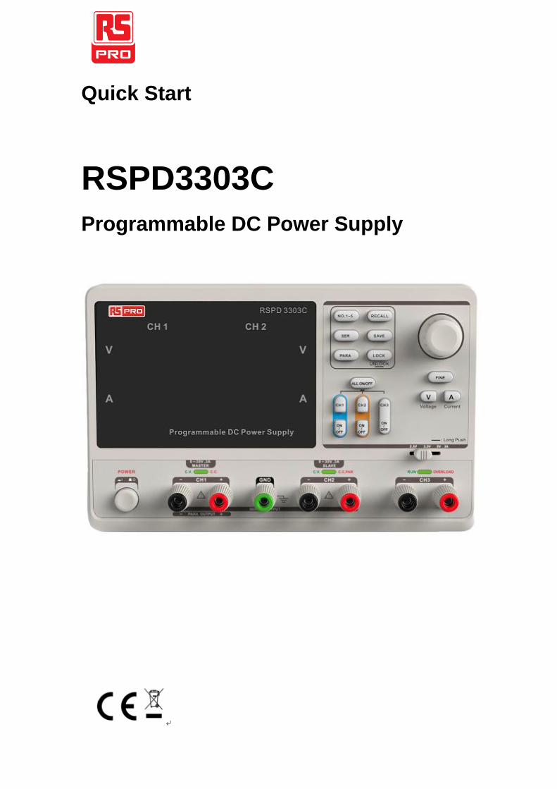
Quick Start
RSPD3303C
Programmable DC Power Supply
2
General Safety Summary
Please review the following safety precautions carefully to avoid
personal injury or damage to this product or any product connected
to it. To prevent potential danger, please use the instrument as
specified.
Use proper power cord
Only the power cord designed for the instrument and authorized by
local country could be used.
Power supply
AC Input Voltages: 100V/110V/220V/230V ±10%, 50/60Hz.
Use proper fuse
The fuse types: 100V/110V(T6.3A/250V) 220V/230V
(T3.15A/250V)
Make sure to use the correct type of fuse before turning on the
instrument.
Do not connect the power cord before replacing the fuse.
Find out the reason why the fuse burned out before replacing the
fuse.
Ground the instrument
The instrument is grounded through the protective terra conductor
of the power cord. To avoid electric shock, the grounding conductor
must be connected to the earth. Make sure that the instrument is
properly grounded before any inputs or outputs.
Observe all terminal ratings
To avoid fire or electric shock, please observe all ratings and
symbols on the instrument. Read this guide carefully to know more
details about the ratings before connection.
3
Keep proper ventilation
Inadequate ventilation may cause an increase of temperature,
which will lead to further damage. Please keep proper ventilation
and check the fan and air-vents regularly when using the
instrument.
Operate condition
Location: indoor, no strong light, almost no Interfering pollution
Comparative humidity: <80%
Altitude: <2000m
Temperature: 0℃ to 40℃
Do not operate in an explosive atmosphere
To avoid personal injury or damage to instrument, please do not
operate in an explosive atmosphere.
Keep surface of the product clean and dry
To avoid dust or moisture in the air, which may influence the
performance of the instrument, please keep surface of
the product clean and dry.
4
Safety Terms and Symbols
Terms may appear on the product:
DANGER: Indicates direct injury or hazard that may happen.
WARNING: Indicates potential injury or hazard that may happen.
CAUTION: Indicates potential damage to the instrument or other
property that may happen.
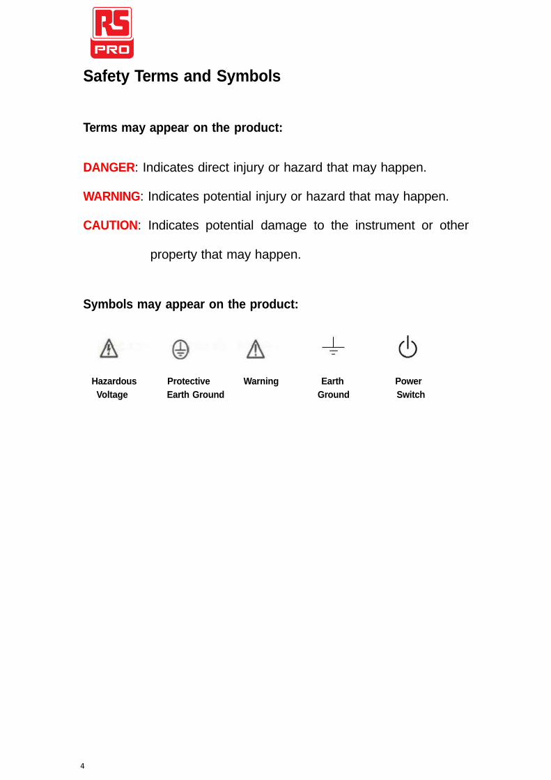
Symbols may appear on the product:
Hazardous Protective Warning Earth Power
Voltage Earth Ground Ground Switch
5
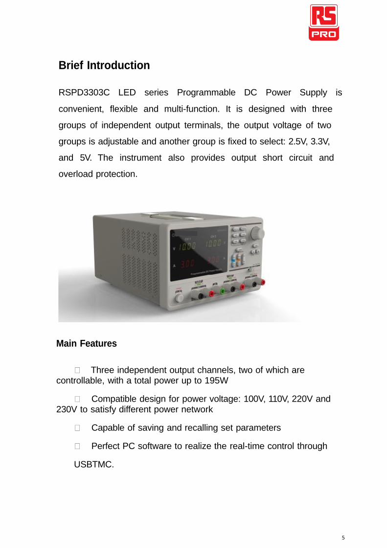
Brief Introduction
RSPD3303C LED series Programmable DC Power Supply is
convenient, flexible and multi-function. It is designed with three
groups of independent output terminals, the output voltage of two
groups is adjustable and another group is fixed to select: 2.5V, 3.3V,
and 5V. The instrument also provides output short circuit and
overload protection.
Main Features
Three independent output channels, two of which are
controllable, with a total power up to 195W
Compatible design for power voltage: 100V, 110V, 220V and
230V to satisfy different power network
Capable of saving and recalling set parameters
Perfect PC software to realize the real-time control through
USBTMC.
6
Chapter 1 Quick Guide
In this chapter, we mainly introduce the panel display interface
and inspecting the new machine. Reading the following steps will give you a quick understanding on operation.
General Inspection
1. Inspect the shipping container.
Keep the damaged shipping container or cushioning material
until the contents of the shipment have been completely
checked and the instrument has passed both electrical and
mechanical tests.
2. Inspect the instrument.
If there are instruments found damaged, defective or failure in
electrical and mechanical tests, please contact us.
3. Check the accessories.
Please check the accessories according to the packing list. If the
accessories are incomplete or damaged, please contact us .
7
Safety Considerations
To ensure that the instrument can work normally, please conduct
necessary inspection before using the RSPD3303C.
Input Power Requirement
The RSPD3303C allows a 50Hz/60Hz frequency, and four levels of
AC power: 100V/120V/220V/230V. You can select required power
voltage with the “DIP Switch ” at the rear panel according to the
actual demand.
Warning
To switch to the required power voltage, please disconnect the
power cord first.
Electrical Check
Please use the power cord provided and connect the
instrument to AC power. Check the power as follows.
1. Connect the power supply
Warning
To avoid electric shock, please make sure that the instrument is
grounded correctly.
2. Turn on the power switch
Press the button POWER to enter boot interface, the system
then returns to the default setting.
8
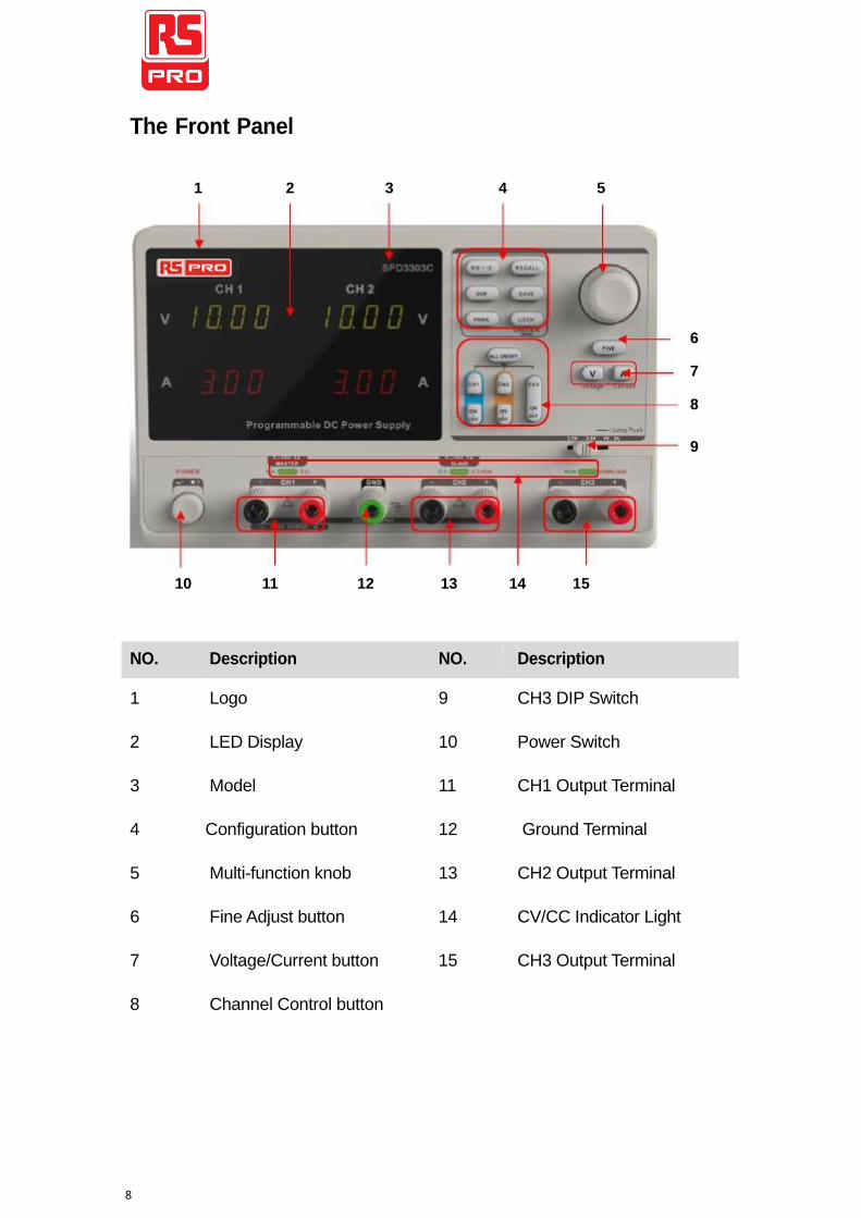
The Front Panel
1 2 3 4 5
6 7 8
9
10 11 12 13 14 15
NO. Description NO. Description
1 Logo 9 CH3 DIP Switch
2 LED Display 10 Power Switch
3 Model 11 CH1 Output Terminal
4 Configuration button 12 Ground Terminal
5 Multi-function knob 13 CH2 Output Terminal
6 Fine Adjust button 14 CV/CC Indicator Light
7 Voltage/Current button 15 CH3 Output Terminal
8 Channel Control button
9
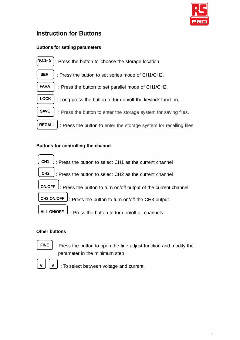
Instruction for Buttons
Buttons for setting parameters
NO.1- 5 : Press the button to choose the storage location
SER
PARA
LOCK
SAVE
: Press the button to set series mode of CH1/CH2.
: Press the button to set parallel mode of CH1/CH2.
: Long press the button to turn on/off the keylock function.
: Press the button to enter the storage system for saving files.
RECALL : Press the button to enter the storage system for recalling files.
Buttons for controlling the channel
CH1
CH2
: Press the button to select CH1 as the current channel
: Press the button to select CH2 as the current channel
ON/OFF : Press the button to turn on/off output of the current channel
CH3 ON/OFF : Press the button to turn on/off the CH3 output.
ALL ON/OFF
Other buttons
: Press the button to turn on/off all channels
FINE
V A
: Press the button to open the fine adjust function and modify the
parameter in the minimum step
: To select between voltage and current.
10
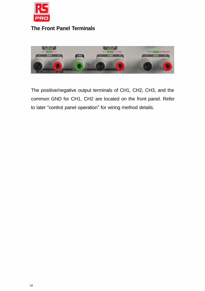
The Front Panel Terminals
The positive/negative output terminals of CH1, CH2, CH3, and the
common GND for CH1, CH2 are located on the front panel. Refer
to later “control panel operation” for wiring method details.
11
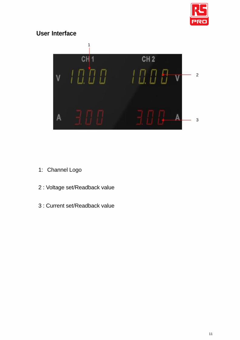
User Interface
1
2
3
1: Channel Logo
2 : Voltage set/Readback value
3 : Current set/Readback value
12
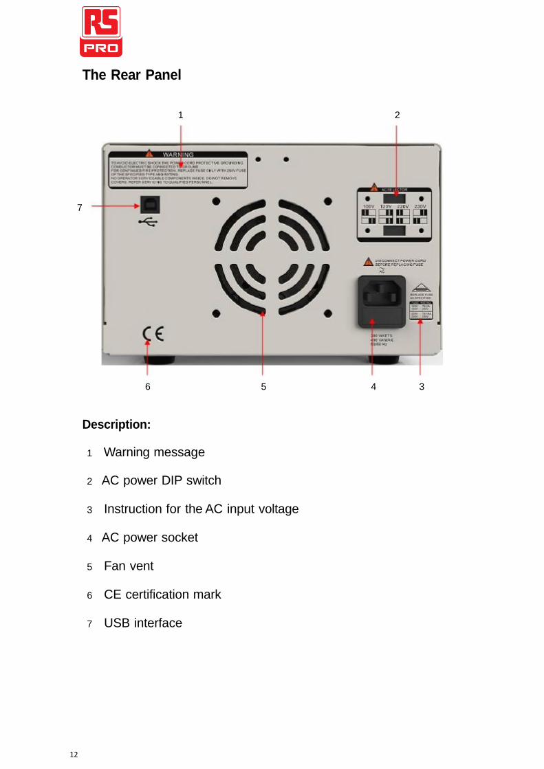
The Rear Panel
1 2
7
6 5 4 3
Description:
1 Warning message
2 AC power DIP switch
3 Instruction for the AC input voltage
4 AC power socket
5 Fan vent
6 CE certification mark
7 USB interface
13
Output Checking
To ensure the instrument is operating correctly, please check the output voltage and current before load is connected.
1. Output voltage checking
(1) With the instrument no load, turn on the power, and make
sure the current value displaying is not zero
(2) Check the output voltage of CH1/CH2
Turn on CH1/CH2 channel and the instrument will work
in CV mode. Check whether the voltage value is
adjustable from 0V to 32V.
2. Current output check
(1) Turn on the power.
(2) Check the output current of CH1/CH2.
Use an insulated wire to connect the positive and negative
terminal of CH1/CH2
(3) Turn on CH1/CH2
Select voltage and revolve the knob to set the value to 32V
Select current and revolve the knob to set the value to 0A
Check whether the current value is adjustable from 0A to
3.2A.
14
Chapter 2 Control Panel Operation
In this chapter,the function and operation of RSPD3303C control
panel will be introduced in detail to give you an all-around
understanding of it.
Brief introduction
Output Summary
CH1/CH2 Independent Output
CH3 Independent Output
Parallel Output
Series Output
Save and Recall
15
Output Summary
RSPD3303C is designed with three independent outputs, two of
which are adjustable in voltage value and the other includes a set of
selectable voltage values: 2.5V, 3.3V or 5.0V.
Independent/Parallel/Series
RSPD3303C has three output modes: independent, parallel and
series that could be selected through the track switch on the front
panel. In independent mode, the output current and voltage are
controlled respectively. In parallel mode, the current value is twice
that of single channel. In the series mode, the voltage value is twice
that of single channel.
Constant Current/Voltage
In constant current mode (series/track mode), the current value is rated. When the voltage value are under its rating, the indicator light displays red. The instrument will automatically return to constant voltage mode when the current value is under rated. In parallel 1 mode, the accessory channel remains in constant current mode neglecting shift of the current value. In constant voltage mode, the voltage value is rated. When the current value are under its rating, the indicator light dispays green. The instrument will turn to constant current mode when the current value returns to its rating.
16
CH1/CH2 Independent Output
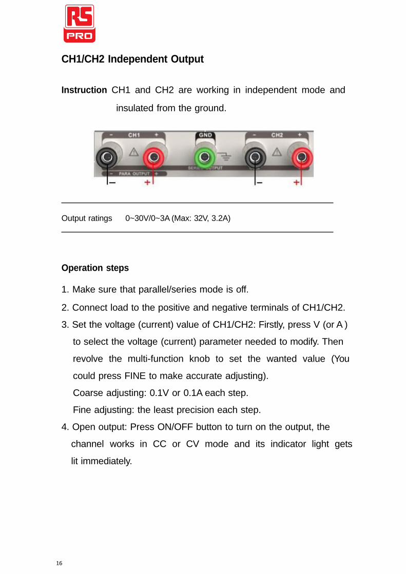
Instruction CH1 and CH2 are working in independent mode and
insulated from the ground.
Output ratings 0~30V/0~3A (Max: 32V, 3.2A)
Operation steps
1. Make sure that parallel/series mode is off.
2. Connect load to the positive and negative terminals of CH1/CH2.
3. Set the voltage (current) value of CH1/CH2: Firstly, press V (or A )
to select the voltage (current) parameter needed to modify. Then
revolve the multi-function knob to set the wanted value (You
could press FINE to make accurate adjusting).
Coarse adjusting: 0.1V or 0.1A each step.
Fine adjusting: the least precision each step.
4. Open output: Press ON/OFF button to turn on the output, the
channel works in CC or CV mode and its indicator light gets
lit immediately.
17
CH3 Independent mode
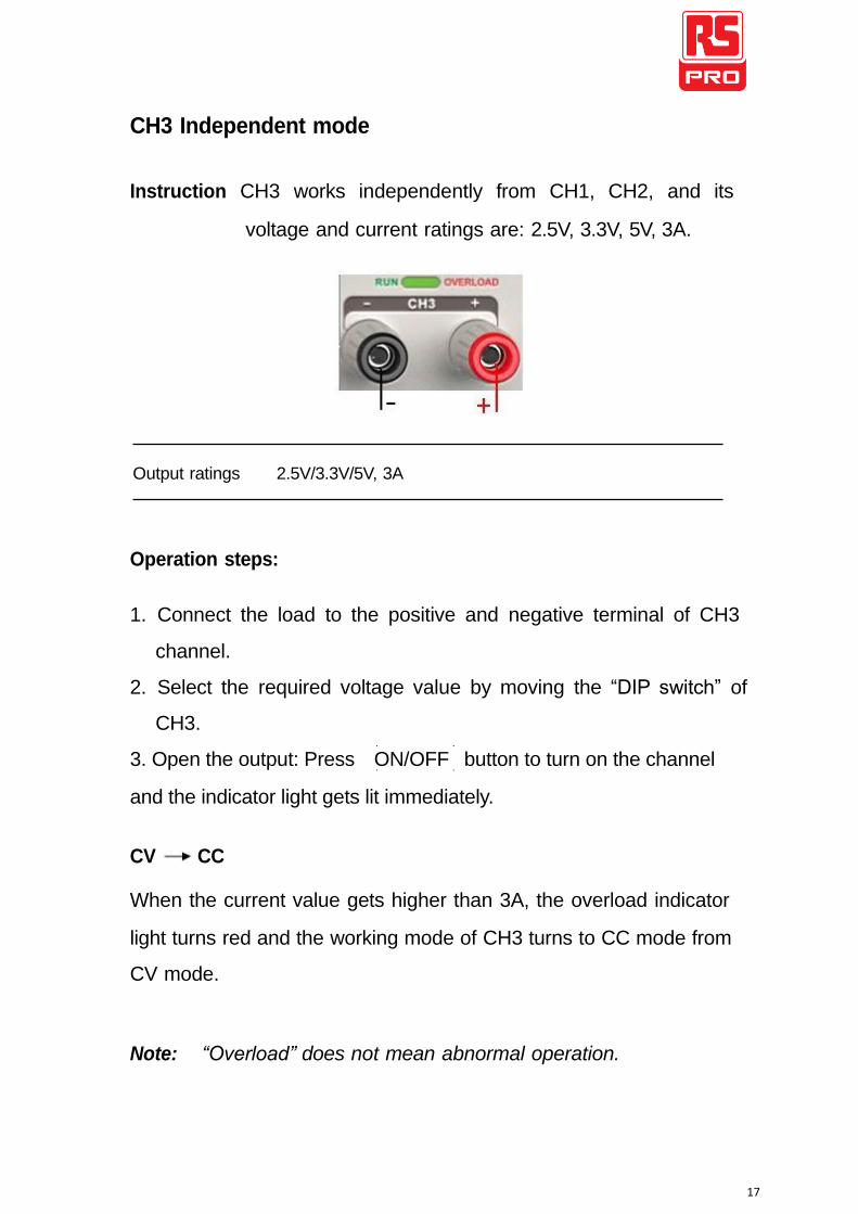
Instruction CH3 works independently from CH1, CH2, and its
voltage and current ratings are: 2.5V, 3.3V, 5V, 3A.
Output ratings 2.5V/3.3V/5V, 3A
Operation steps:
1. Connect the load to the positive and negative terminal of CH3
channel.
2. Select the required voltage value by moving the “DIP switch” of
CH3.
3. Open the output: Press ON/OFF button to turn on the channel and the indicator light gets lit immediately.
CV CC
When the current value gets higher than 3A, the overload indicator
light turns red and the working mode of CH3 turns to CC mode from
CV mode.
Note: “Overload” does not mean abnormal operation.
18
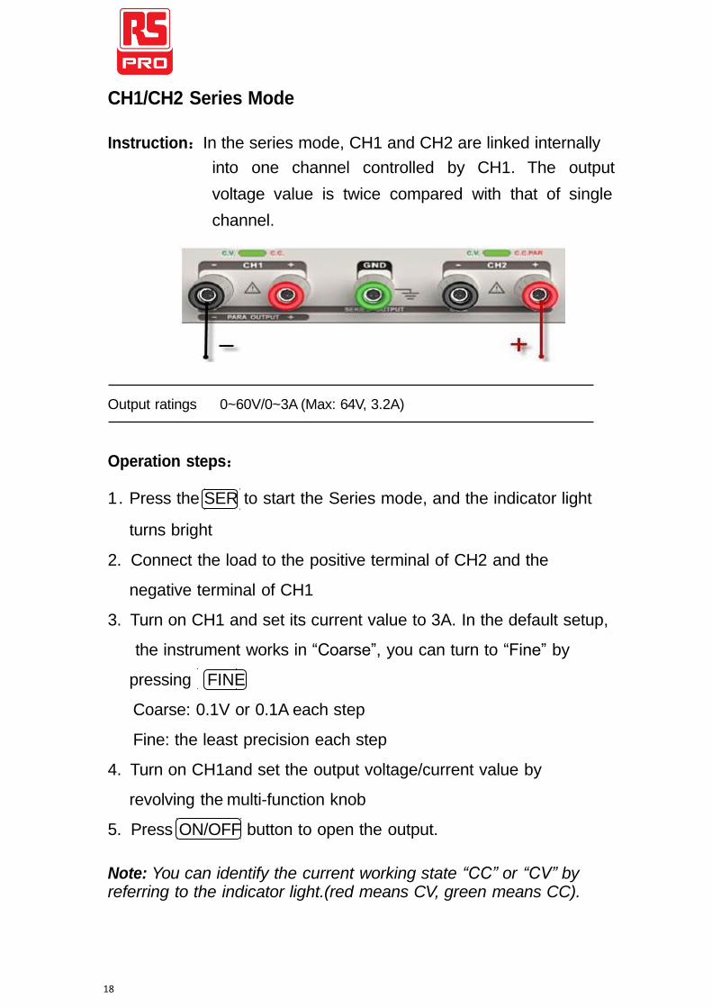
CH1/CH2 Series Mode
Instruction:In the series mode, CH1 and CH2 are linked internally
into one channel controlled by CH1. The output
voltage value is twice compared with that of single
channel.
Output ratings 0~60V/0~3A (Max: 64V, 3.2A)
Operation steps:
1. Press the SER to start the Series mode, and the indicator light
turns bright
2. Connect the load to the positive terminal of CH2 and the
negative terminal of CH1
3. Turn on CH1 and set its current value to 3A. In the default setup,
the instrument works in “Coarse”, you can turn to “Fine” by
pressing FINE
Coarse: 0.1V or 0.1A each step
Fine: the least precision each step
4. Turn on CH1and set the output voltage/current value by
revolving the multi-function knob
5. Press ON/OFF button to open the output.
Note: You can identify the current working state “CC” or “CV” by
referring to the indicator light.(red means CV, green means CC).
19
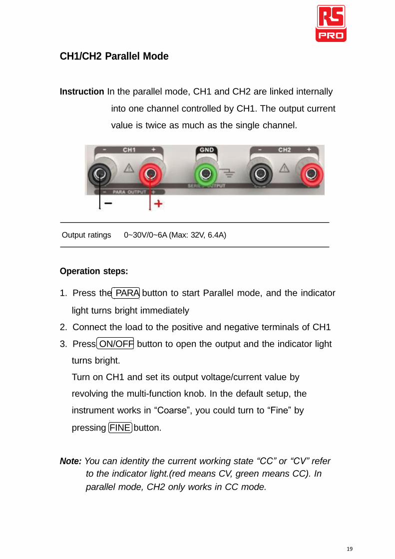
CH1/CH2 Parallel Mode
Instruction In the parallel mode, CH1 and CH2 are linked internally
into one channel controlled by CH1. The output current
value is twice as much as the single channel.
Output ratings 0~30V/0~6A (Max: 32V, 6.4A)
Operation steps:
1. Press the PARA button to start Parallel mode, and the indicator
light turns bright immediately
2. Connect the load to the positive and negative terminals of CH1
3. Press ON/OFF button to open the output and the indicator light
turns bright.
Turn on CH1 and set its output voltage/current value by
revolving the multi-function knob. In the default setup, the
instrument works in “Coarse”, you could turn to “Fine” by
pressing FINE button.
Note: You can identity the current working state “CC” or “CV” refer
to the indicator light.(red means CV, green means CC). In
parallel mode, CH2 only works in CC mode.
20
Save and Recall
Five groups of setups can be saved in memory. Contents of setups
including:
Independent/series/parallel mode
Output voltage/current value
Steps for saving setup
1. Set the state needed to save
2. Press SAVE to enter the save interface
3. Select the wanted file group by pressing NO.1-5
4. Press SAVE again to save the current state to the specified file
group.
Steps for recalling setup
1. Press RECALL to enter the recall interface
2. Select the wanted file group by pressing NO.1-5
3. Press RECALL again to read the previously saved file.
21
Version Upgrade
The software of the instrument is upgraded with a fixed name file
via PC management software with USBTMC. The upgrade method
is below:
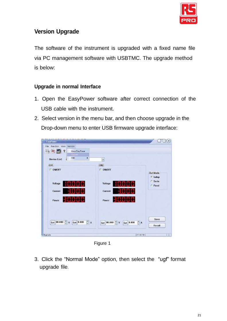
Upgrade in normal Interface
1. Open the EasyPower software after correct connection of the
USB cable with the instrument.
2. Select version in the menu bar, and then choose upgrade in the
Drop-down menu to enter USB firmware upgrade interface:
Figure 1
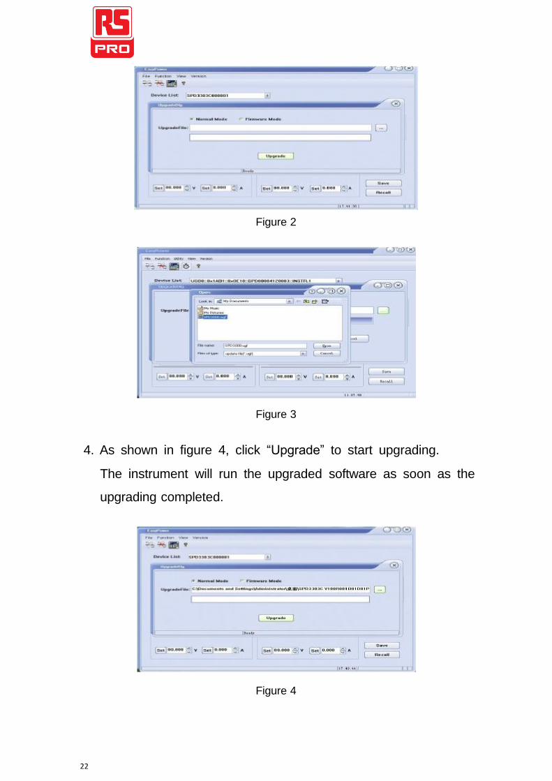
3. Click the “Normal Mode” option, then select the “ugf” format
upgrade file.
22
Figure 2
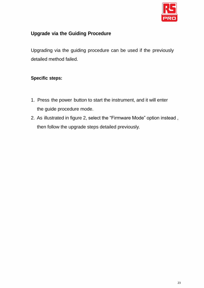
Figure 3
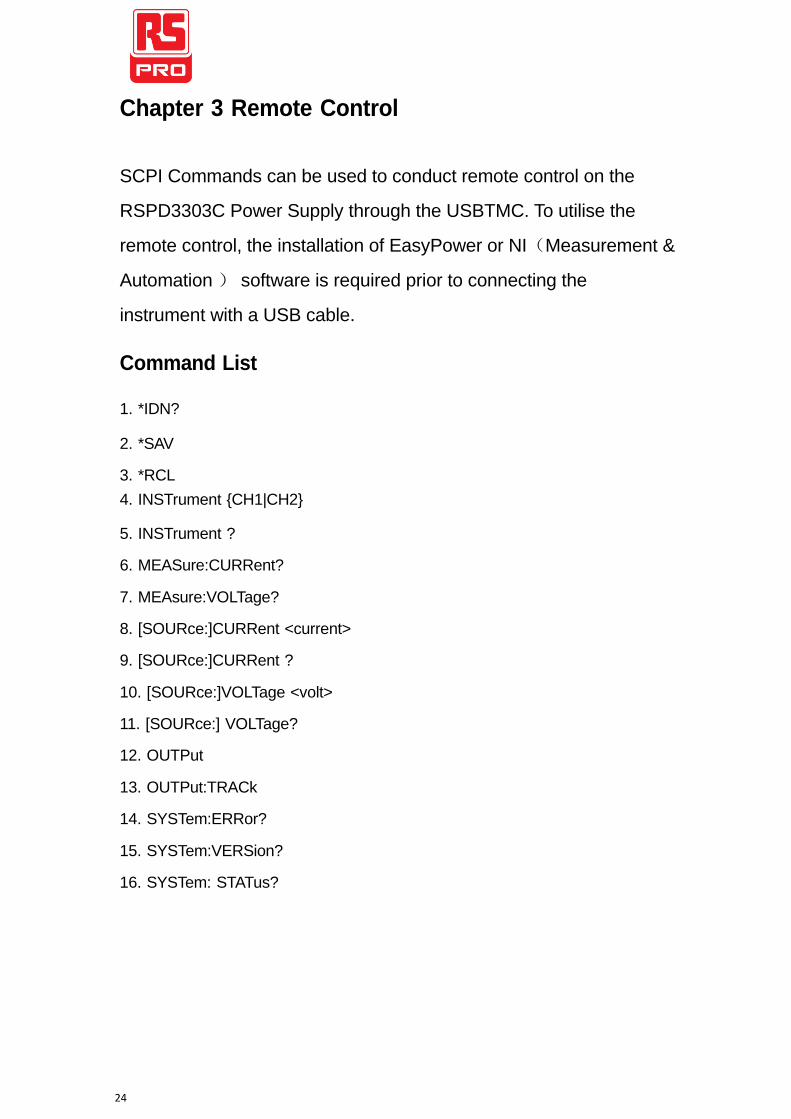
4. As shown in figure 4, click “Upgrade” to start upgrading.
The instrument will run the upgraded software as soon as the
upgrading completed.
Figure 4
23
Upgrade via the Guiding Procedure
Upgrading via the guiding procedure can be used if the previously
detailed method failed.
Specific steps:
1. Press the power button to start the instrument, and it will enter
the guide procedure mode.
2. As illustrated in figure 2, select the “Firmware Mode” option instead ,
then follow the upgrade steps detailed previously.
24
Chapter 3 Remote Control
SCPI Commands can be used to conduct remote control on the RSPD3303C Power Supply through the USBTMC. To utilise the remote control, the installation of EasyPower or NI(Measurement & Automation ) software is required prior to connecting the instrument with a USB cable.
Command List
1. *IDN?
2. *SAV 3. *RCL
4. INSTrument {CH1|CH2} 5. INSTrument ? 6. MEASure:CURRent? 7. MEAsure:VOLTage? 8. [SOURce:]CURRent <current> 9. [SOURce:]CURRent ? 10. [SOURce:]VOLTage <volt> 11. [SOURce:] VOLTage? 12. OUTPut 13. OUTPut:TRACk 14. SYSTem:ERRor? 15. SYSTem:VERSion? 16. SYSTem: STATus?
25
Command Description
1.*IDN?
Command format *IDN?
Description Query the manufacturer, product model, series NO. and
software version.
Return Info Manufacturer, product model, series NO., software
version.
Example RSPD3303C, SPD00001130025, .01.01.02.
2.*SAV
Command format *SAV <name>
Description Save the current state in nonvolatile memory with the
specified name.
Example *SAV 1
3.*RCL
Command format *RCL <name>
Description Recall state that previously saved.
Example *RCL 1
26
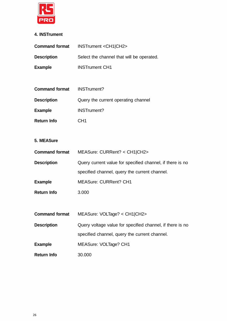
4. INSTrument
Command format INSTrument <CH1|CH2>
Description Select the channel that will be operated.
Example INSTrument CH1
Command format INSTrument?
Description Query the current operating channel
Example INSTrument?
Return Info CH1
5. MEASure
Command format MEASure: CURRent? < CH1|CH2>
Description Query current value for specified channel, if there is no
specified channel, query the current channel.
Example MEASure: CURRent? CH1
Return Info 3.000
Command format MEASure: VOLTage? < CH1|CH2>
Description Query voltage value for specified channel, if there is no
specified channel, query the current channel.
Example MEASure: VOLTage? CH1
Return Info 30.000
27
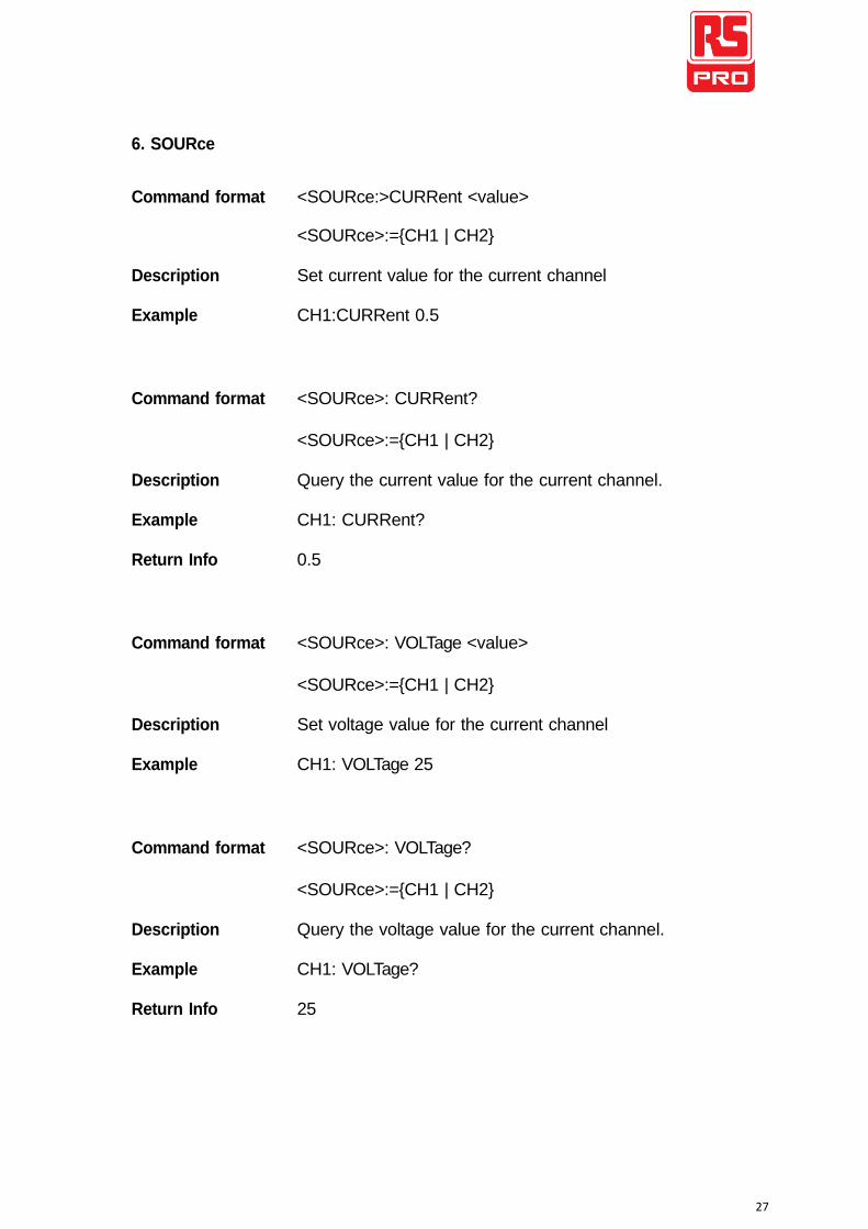
6. SOURce
Command format <SOURce:>CURRent <value>
<SOURce>:={CH1 | CH2}
Description Set current value for the current channel
Example CH1:CURRent 0.5
Command format <SOURce>: CURRent?
<SOURce>:={CH1 | CH2}
Description Query the current value for the current channel.
Example CH1: CURRent?
Return Info 0.5
Command format <SOURce>: VOLTage <value>
<SOURce>:={CH1 | CH2}
Description Set voltage value for the current channel
Example CH1: VOLTage 25
Command format <SOURce>: VOLTage?
<SOURce>:={CH1 | CH2}
Description Query the voltage value for the current channel.
Example CH1: VOLTage?
Return Info 25
28
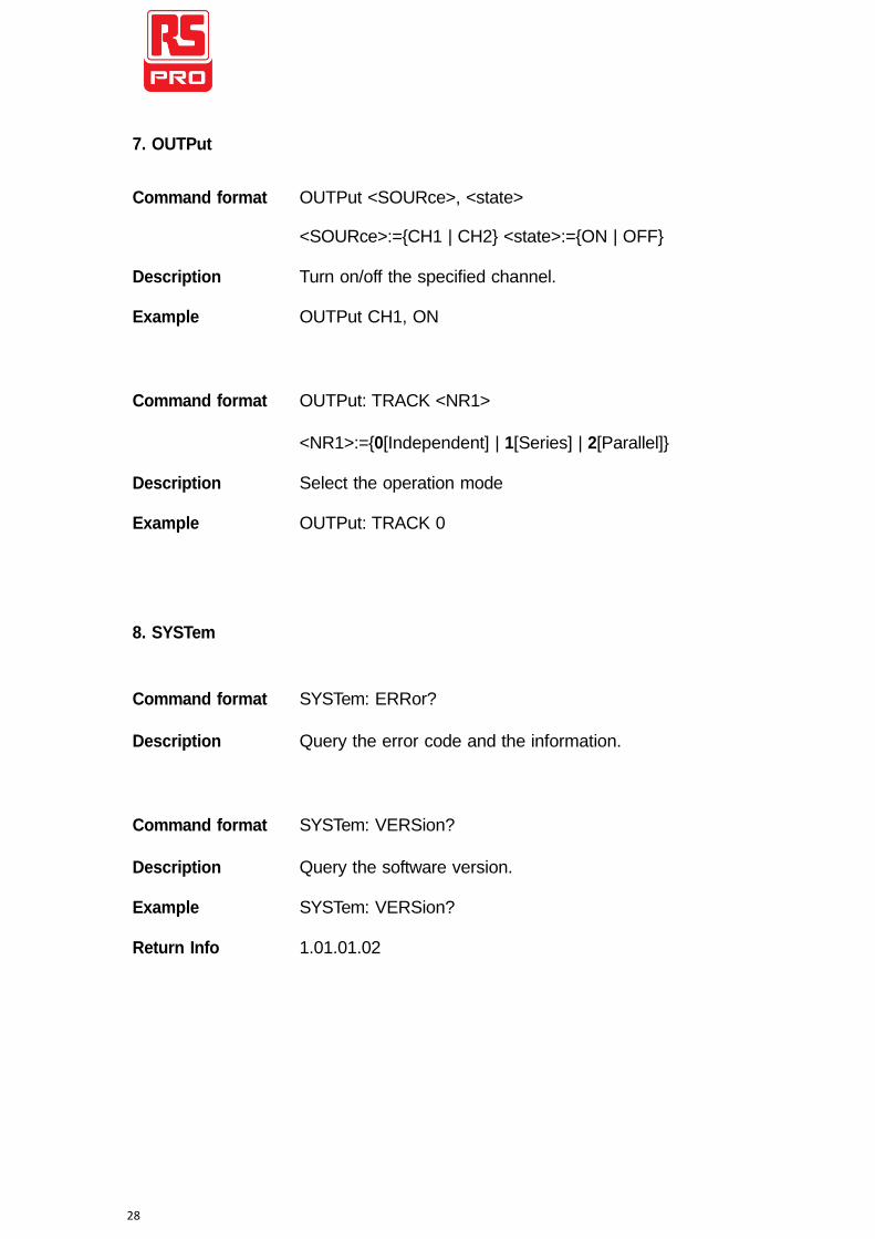
7. OUTPut Command format OUTPut <SOURce>, <state>
<SOURce>:={CH1 | CH2} <state>:={ON | OFF}
Description Turn on/off the specified channel.
Example OUTPut CH1, ON
Command format OUTPut: TRACK <NR1>
<NR1>:={0[Independent] | 1[Series] | 2[Parallel]}
Description Select the operation mode
Example OUTPut: TRACK 0
8. SYSTem
Command format SYSTem: ERRor?
Description Query the error code and the information.
Command format SYSTem: VERSion?
Description Query the software version.
Example SYSTem: VERSion?
Return Info 1.01.01.02
29
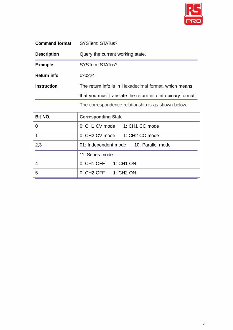
Command format SYSTem: STATus?
Description Query the current working state.
Example SYSTem: STATus?
Return info 0x0224
Instruction The return info is in Hexadecimal format, which means
that you must translate the return info into binary format. The correspondence relationship is as shown below.
Bit NO. Corresponding State
0 0: CH1 CV mode 1: CH1 CC mode
1 0: CH2 CV mode 1: CH2 CC mode
2,3 01: Independent mode 10: Parallel mode
11: Series mode
4 0: CH1 OFF 1: CH1 ON
5 0: CH2 OFF 1: CH2 ON
30
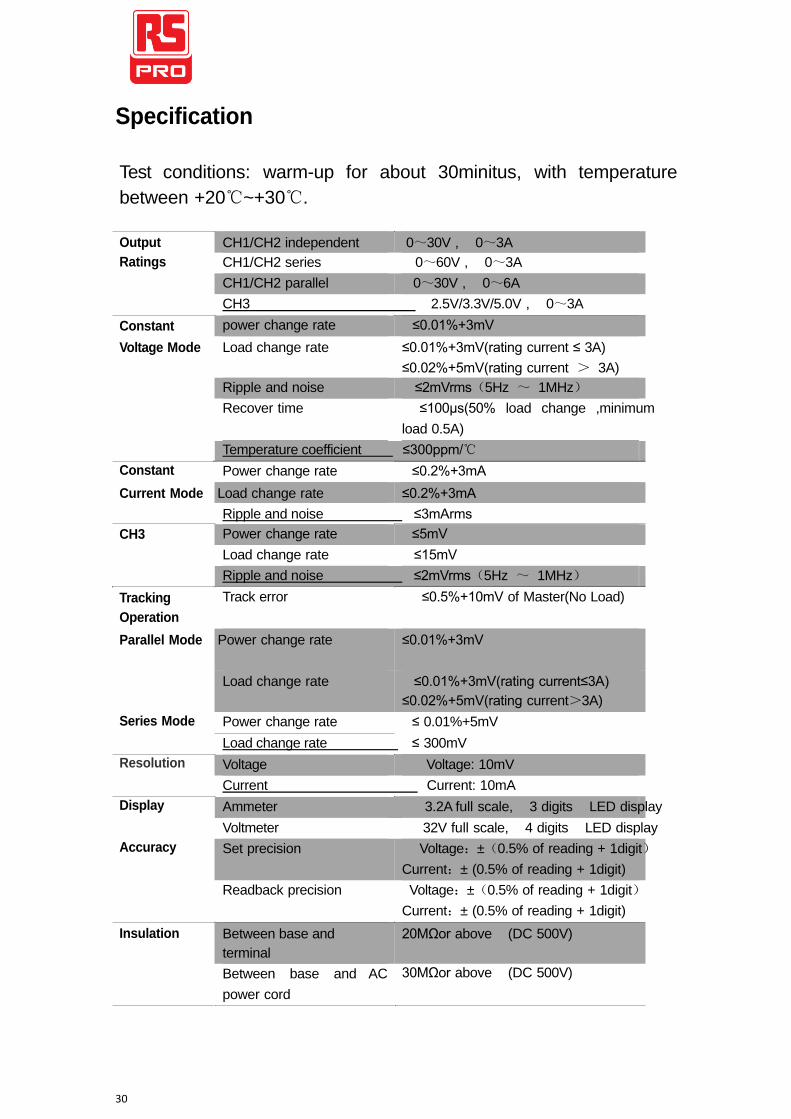
Specification
Test conditions: warm-up for about 30minitus, with temperature
between +20℃~+30℃.
Output
Ratings
Constant
CH1/CH2 independent 0~30V , 0~3A
CH1/CH2 series 0~60V , 0~3A
CH1/CH2 parallel 0~30V , 0~6A
CH3 2.5V/3.3V/5.0V , 0~3A
power change rate ≤0.01%+3mV Voltage Mode Load change rate ≤0.01%+3mV(rating current ≤ 3A)
Constant
≤0.02%+5mV(rating current > 3A)
Ripple and noise ≤2mVrms(5Hz ~ 1MHz)
Recover time ≤100μs(50% load change ,minimum
load 0.5A)
Temperature coefficient ≤300ppm/℃
Power change rate ≤0.2%+3mA Current Mode Load change rate ≤0.2%+3mA
CH3
Tracking
Operation
Ripple and noise ≤3mArms
Power change rate ≤5mV
Load change rate ≤15mV
Ripple and noise ≤2mVrms(5Hz ~ 1MHz)
Track error ≤0.5%+10mV of Master(No Load)
Parallel Mode Power change rate ≤0.01%+3mV
Series Mode
Resolution
Display
Accuracy
Load change rate ≤0.01%+3mV(rating current≤3A)
≤0.02%+5mV(rating current>3A)
Power change rate ≤ 0.01%+5mV
Load change rate ≤ 300mV
Voltage Voltage: 10mV
Current Current: 10mA
Ammeter 3.2A full scale, 3 digits LED display
Voltmeter 32V full scale, 4 digits LED display
Set precision Voltage:±(0.5% of reading + 1digit)
Current:± (0.5% of reading + 1digit)
Readback precision Voltage:±(0.5% of reading + 1digit)
Current:± (0.5% of reading + 1digit)
Insulation
Between base and
terminal
Between base and AC
power cord
20MΩor above (DC 500V)
30MΩor above (DC 500V)
31
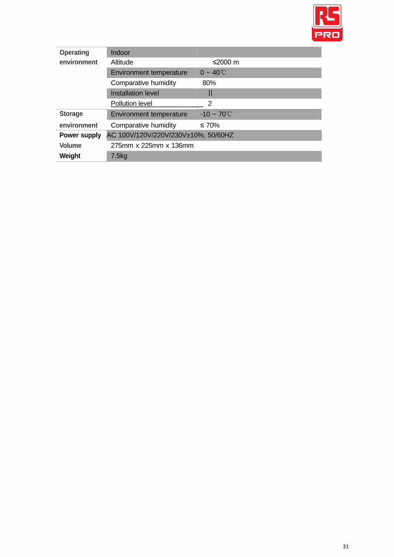
Operating
environment
Storage
Indoor
Altitude ≤2000 m
Environment temperature 0 ~ 40℃
Comparative humidity 80%
Installation level Ⅱ
Pollution level 2
Environment temperature -10 ~ 70℃ environment Comparative humidity ≤ 70%
Power supply AC 100V/120V/220V/230V±10%, 50/60HZ
Volume 275mm x 225mm x 136mm
Weight 7.5kg