Embed Size (px)
Citation preview
Te
st &
Mea
sure
men
t
Data
She
et |
16.0
1R&S®FSU Spectrum AnalyzerSpecifications
FSU_dat-sw_en_0758-0016-22_v1601_cover.indd 1 22.05.2012 18:35:42
Version 16.01, May 2012
2 Rohde & Schwarz R&S®FSU Spectrum Analyzer
CONTENTS Specifications .................................................................................................................................................................. 3 Frequency ........................................................................................................................................................................ 3 Sweep ............................................................................................................................................................................... 4 Resolution bandwidths ................................................................................................................................................... 4 Level ................................................................................................................................................................................. 5 I/Q data ............................................................................................................................................................................. 9 Audio demodulation ....................................................................................................................................................... 9 Trigger functions .......................................................................................................................................................... 10 Inputs and outputs (front panel) .................................................................................................................................. 10 Inputs and outputs (rear panel) ................................................................................................................................... 11 General specifications .................................................................................................................................................. 12
R&S®FSU-B9 tracking generator, R&S®FSU-B12 attenuator for tracking generator (not available for R&S®FSU67) .......................... 13 R&S®FSU-B21 LO/IF ports for external mixers (for R&S®FSU26/43/46/50/67 only) ............................................................................ 15 R&S®FSU-B23 RF preamplifier (for R&S®FSU26 only, requires R&S®FSU-B25 option) ..................................................................... 16 R&S®FSU-B24 preamplifier (for R&S®FSU26/43/46/50 only) ............................................................................................................... 17 R&S®FSU-B25 electronic attenuator and low-noise preamplifier, R&S®FSU-B85 extended specifications for low-noise preamplifier 19 R&S®FSU-B27 broadband FM demodulator output .............................................................................................................................. 20
Ordering information .................................................................................................................................................... 21 Options .......................................................................................................................................................................... 22 Recommended extras ................................................................................................................................................... 23
Version 16.01, May 2012
Rohde & Schwarz R&S®FSU Spectrum Analyzer 3
Specifications Specifications apply under the following conditions: 30 minutes warm-up time at ambient temperature, specified environmental conditions met, calibration cycle adhered to, and all internal automatic adjustments performed. Data without tolerances: typical values only. Data designated "nominal" applies to design parameters and is not tested.
Frequency Frequency range R&S®FSU3: DC coupled 20 Hz to 3.6 GHz
AC coupled 1 MHz to 3.6 GHz R&S®FSU8: DC coupled 20 Hz to 8 GHz AC coupled 1 MHz to 8 GHz R&S®FSU26: DC coupled 20 Hz to 26.5 GHz AC coupled 10 MHz to 26.5 GHz R&S®FSU43: DC coupled 20 Hz to 43 GHz R&S®FSU46: DC coupled 20 Hz to 46 GHz R&S®FSU50: DC coupled 20 Hz to 50 GHz R&S®FSU67: DC coupled 20 Hz to 67 GHz
Frequency resolution 0.01 Hz
Reference frequency, internal, nominal standard OCXO Aging per day after 30 days of continuous operation 1 × 10⁻⁹
Aging per year after 30 days of continuous operation 1 × 10⁻⁷
Temperature drift +5 °C to +45 °C 8 × 10⁻⁸ Total error per year 1.8 × 10⁻⁷ Reference frequency, internal, nominal R&S®FSU-B4 option Aging per day after 30 days of continuous operation 2 × 10⁻¹⁰
Aging per year after 30 days of continuous operation 3 × 10⁻⁸
Temperature drift +5 °C to +45 °C 1 × 10⁻⁹ Total error per year 5 × 10⁻⁸ External reference frequency 1 MHz to 20 MHz, 1 Hz steps
Frequency display with marker or frequency counter Marker resolution 1 Hz
Uncertainty ±(marker frequency × reference uncertainty + 10 % × resolution bandwidth + ½ (span/(sweep points –1)) + 1 Hz)
Marker tuning frequency stepsize default span/624 marker stepsize = sweep points span/(sweep points – 1)
Frequency counter resolution selectable 0.1 Hz to 10 kHz Count accuracy S/N > 25 dB ±(frequency × reference error +
½ (last digit)) Display range for frequency axis 0 Hz, 10 Hz to max. frequency
Resolution 0.1 Hz Max. span deviation 1 %
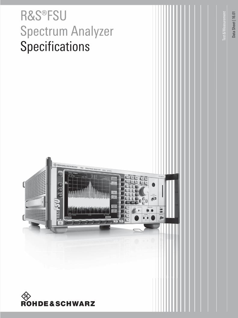
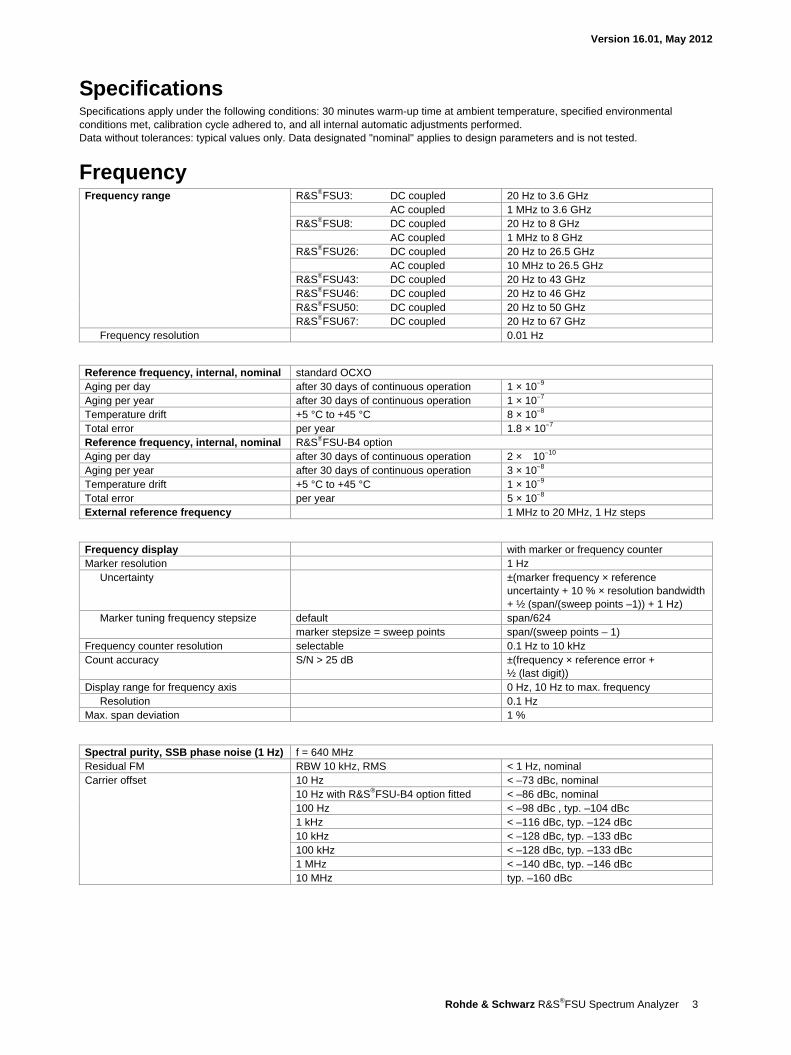
Spectral purity, SSB phase noise (1 Hz) f = 640 MHz Residual FM RBW 10 kHz, RMS < 1 Hz, nominal Carrier offset 10 Hz < –73 dBc, nominal
10 Hz with R&S®FSU-B4 option fitted < –86 dBc, nominal 100 Hz < –98 dBc , typ. –104 dBc 1 kHz < –116 dBc, typ. –124 dBc 10 kHz < –128 dBc, typ. –133 dBc 100 kHz < –128 dBc, typ. –133 dBc 1 MHz < –140 dBc, typ. –146 dBc 10 MHz typ. –160 dBc
Version 16.01, May 2012
4 Rohde & Schwarz R&S®FSU Spectrum Analyzer
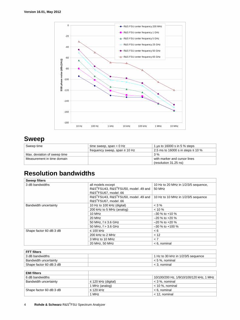
-180
-160
-140
-120
-100
-80
-60
-40
-20
0
10 Hz 100 Hz 1 kHz 10 kHz 100 kHz 1 MHz 10 MHz
SS
B p
ha
se
no
ise
(d
Bc
(1H
z))
R&S FSU center frequency 200 MHz
R&S FSU center frequency 1 GHz
R&S FSU center frequency 5 GHz
R&S FSU center frequency 25 GHz
R&S FSU center frequency 50 GHz
R&S FSU center frequency 65 GHz
Sweep Sweep time time sweep, span = 0 Hz 1 µs to 16000 s in 5 % steps
frequency sweep, span ≥ 10 Hz 2.5 ms to 16000 s in steps ≤ 10 % Max. deviation of sweep time 3 % Measurement in time domain with marker and cursor lines
(resolution 31.25 ns)
Resolution bandwidths Sweep filters 3 dB bandwidths all models except
R&S®FSU43, R&S®FSU50, model .49 and R&S®FSU67, model .66
10 Hz to 20 MHz in 1/2/3/5 sequence, 50 MHz
R&S®FSU43, R&S®FSU50, model .49 and R&S®FSU67, model .66
10 Hz to 10 MHz in 1/2/3/5 sequence
Bandwidth uncertainty 10 Hz to 100 kHz (digital) < 3 % 200 kHz to 5 MHz (analog) < 10 % 10 MHz –30 % to +10 % 20 MHz –20 % to +20 % 50 MHz, f ≤ 3.6 GHz –20 % to +20 % 50 MHz, f > 3.6 GHz –30 % to +100 %
Shape factor 60 dB:3 dB ≤ 100 kHz < 6 200 kHz to 2 MHz < 12 3 MHz to 10 MHz < 7 20 MHz, 50 MHz < 6, nominal
FFT filters 3 dB bandwidths 1 Hz to 30 kHz in 1/2/3/5 sequence Bandwidth uncertainty < 5 %, nominal Shape factor 60 dB:3 dB < 3, nominal
EMI filters 6 dB bandwidths 10/100/200 Hz, 1/9/10/100/120 kHz, 1 MHz Bandwidth uncertainty ≤ 120 kHz (digital) < 3 %, nominal
1 MHz (analog) < 10 %, nominal Shape factor 60 dB:3 dB ≤ 120 kHz < 6, nominal
1 MHz < 12, nominal
Version 16.01, May 2012
Rohde & Schwarz R&S®FSU Spectrum Analyzer 5
Channel filters Bandwidths 100/200/300/500 Hz
1/1.5/2/2.4/2.7/3/3.4/4/4.5/5/6/8.5/9/10/ 12.5/14/15/16/18 (RRC)/20/21/ 24.3 (RRC)/25/30/50/100/150/192/200/ 300/500 kHz 1/1.2288/1.28 (RRC)/1.5/2/3/3.84 (RRC)/ 4.096 (RRC)/5 MHz
Shape factor 60 dB:3 dB < 2, nominal Bandwidth uncertainty < 2 %, nominal
Video bandwidths 1 Hz to 10 MHz in 1/2/3/5 sequence
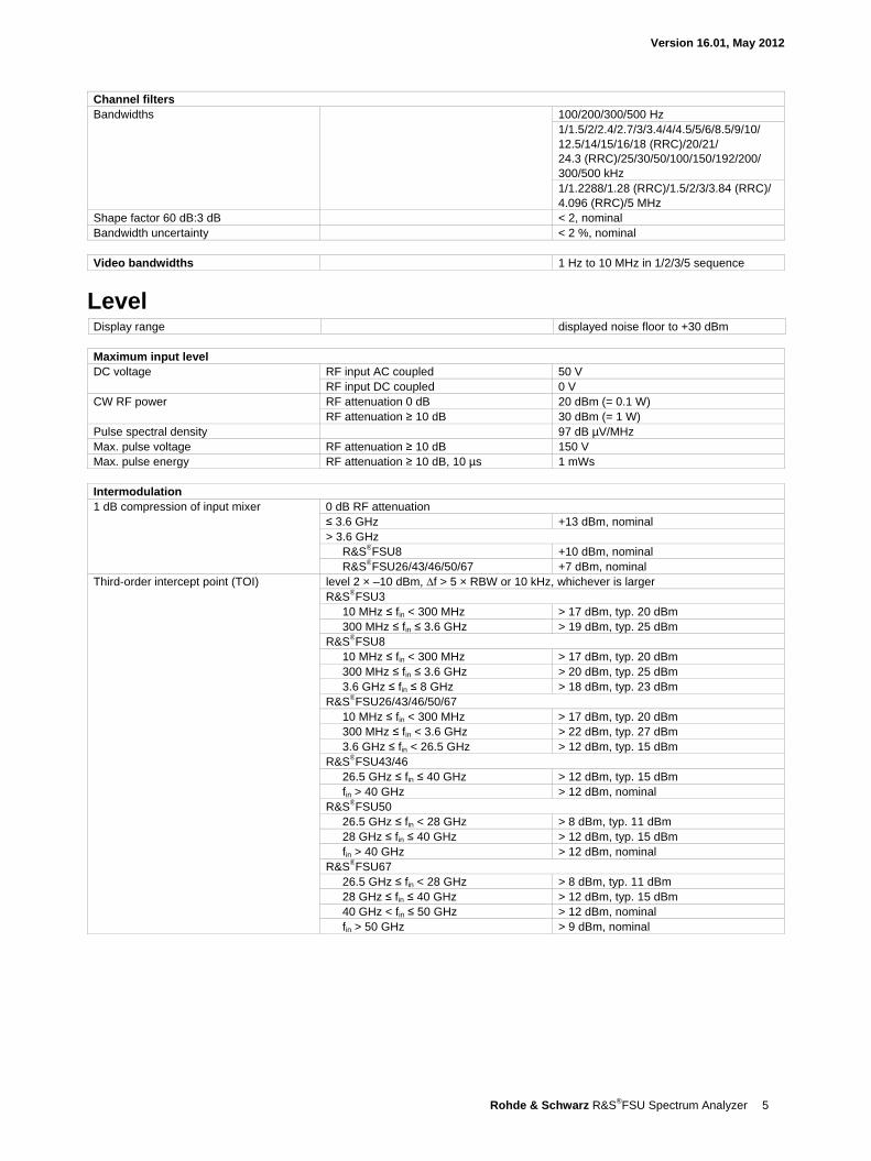
Level Display range displayed noise floor to +30 dBm
Maximum input level DC voltage RF input AC coupled 50 V
RF input DC coupled 0 V CW RF power RF attenuation 0 dB 20 dBm (= 0.1 W)
RF attenuation ≥ 10 dB 30 dBm (= 1 W) Pulse spectral density 97 dB µV/MHz Max. pulse voltage RF attenuation ≥ 10 dB 150 V Max. pulse energy RF attenuation ≥ 10 dB, 10 µs 1 mWs
Intermodulation 1 dB compression of input mixer 0 dB RF attenuation
≤ 3.6 GHz +13 dBm, nominal > 3.6 GHz
R&S®FSU8 +10 dBm, nominal R&S®FSU26/43/46/50/67 +7 dBm, nominal
Third-order intercept point (TOI) level 2 × –10 dBm, ∆f > 5 × RBW or 10 kHz, whichever is larger R&S®FSU3
10 MHz ≤ fin < 300 MHz > 17 dBm, typ. 20 dBm 300 MHz ≤ fin ≤ 3.6 GHz > 19 dBm, typ. 25 dBm
R&S®FSU8 10 MHz ≤ fin < 300 MHz > 17 dBm, typ. 20 dBm 300 MHz ≤ fin ≤ 3.6 GHz > 20 dBm, typ. 25 dBm 3.6 GHz ≤ fin ≤ 8 GHz > 18 dBm, typ. 23 dBm
R&S®FSU26/43/46/50/67 10 MHz ≤ fin < 300 MHz > 17 dBm, typ. 20 dBm 300 MHz ≤ fin < 3.6 GHz > 22 dBm, typ. 27 dBm 3.6 GHz ≤ fin < 26.5 GHz > 12 dBm, typ. 15 dBm
R&S®FSU43/46 26.5 GHz ≤ fin ≤ 40 GHz > 12 dBm, typ. 15 dBm fin > 40 GHz > 12 dBm, nominal
R&S®FSU50 26.5 GHz ≤ fin < 28 GHz > 8 dBm, typ. 11 dBm 28 GHz ≤ fin ≤ 40 GHz > 12 dBm, typ. 15 dBm fin > 40 GHz > 12 dBm, nominal
R&S®FSU67 26.5 GHz ≤ fin < 28 GHz > 8 dBm, typ. 11 dBm 28 GHz ≤ fin ≤ 40 GHz > 12 dBm, typ. 15 dBm 40 GHz < fin ≤ 50 GHz > 12 dBm, nominal fin > 50 GHz > 9 dBm, nominal
Version 16.01, May 2012
6 Rohde & Schwarz R&S®FSU Spectrum Analyzer
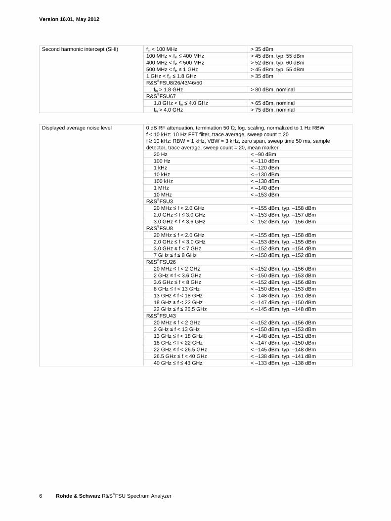
Second harmonic intercept (SHI) fin < 100 MHz > 35 dBm 100 MHz < fin ≤ 400 MHz > 45 dBm, typ. 55 dBm 400 MHz < fin ≤ 500 MHz > 52 dBm, typ. 60 dBm 500 MHz < fin ≤ 1 GHz > 45 dBm, typ. 55 dBm 1 GHz < fin ≤ 1.8 GHz > 35 dBm R&S®FSU8/26/43/46/50
fin > 1.8 GHz > 80 dBm, nominal R&S®FSU67
1.8 GHz < fin ≤ 4.0 GHz > 65 dBm, nominal fin > 4.0 GHz > 75 dBm, nominal
Displayed average noise level 0 dB RF attenuation, termination 50 Ω, log. scaling, normalized to 1 Hz RBW f < 10 kHz: 10 Hz FFT filter, trace average, sweep count = 20 f ≥ 10 kHz: RBW = 1 kHz, VBW = 3 kHz, zero span, sweep time 50 ms, sample detector, trace average, sweep count = 20, mean marker
20 Hz < –90 dBm 100 Hz < –110 dBm 1 kHz < –120 dBm 10 kHz < –130 dBm 100 kHz < –130 dBm 1 MHz < –140 dBm 10 MHz < –153 dBm
R&S®FSU3 20 MHz ≤ f < 2.0 GHz < –155 dBm, typ. –158 dBm 2.0 GHz ≤ f ≤ 3.0 GHz < –153 dBm, typ. –157 dBm 3.0 GHz ≤ f ≤ 3.6 GHz < –152 dBm, typ. –156 dBm
R&S®FSU8 20 MHz ≤ f < 2.0 GHz < –155 dBm, typ. –158 dBm 2.0 GHz ≤ f < 3.0 GHz < –153 dBm, typ. –155 dBm 3.0 GHz ≤ f < 7 GHz < –152 dBm, typ. –154 dBm 7 GHz ≤ f ≤ 8 GHz < –150 dBm, typ. –152 dBm
R&S®FSU26 20 MHz ≤ f < 2 GHz < –152 dBm, typ. –156 dBm 2 GHz ≤ f < 3.6 GHz < –150 dBm, typ. –153 dBm 3.6 GHz ≤ f < 8 GHz < –152 dBm, typ. –156 dBm 8 GHz ≤ f < 13 GHz < –150 dBm, typ. –153 dBm 13 GHz ≤ f < 18 GHz < –148 dBm, typ. –151 dBm 18 GHz ≤ f < 22 GHz < –147 dBm, typ. –150 dBm 22 GHz ≤ f ≤ 26.5 GHz < –145 dBm, typ. –148 dBm
R&S®FSU43 20 MHz ≤ f < 2 GHz < –152 dBm, typ. –156 dBm 2 GHz ≤ f < 13 GHz < –150 dBm, typ. –153 dBm 13 GHz ≤ f < 18 GHz < –148 dBm, typ. –151 dBm 18 GHz ≤ f < 22 GHz < –147 dBm, typ. –150 dBm 22 GHz ≤ f < 26.5 GHz < –145 dBm, typ. –148 dBm 26.5 GHz ≤ f < 40 GHz < –138 dBm, typ. –141 dBm 40 GHz ≤ f ≤ 43 GHz < –133 dBm, typ. –138 dBm
Version 16.01, May 2012
Rohde & Schwarz R&S®FSU Spectrum Analyzer 7
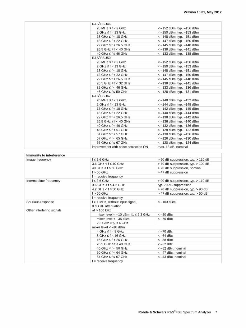
R&S®FSU46 20 MHz ≤ f < 2 GHz < –152 dBm, typ. –156 dBm 2 GHz ≤ f < 13 GHz < –150 dBm, typ. –153 dBm 13 GHz ≤ f < 18 GHz < –148 dBm, typ. –151 dBm 18 GHz ≤ f < 22 GHz < –147 dBm, typ. –150 dBm 22 GHz ≤ f < 26.5 GHz < –145 dBm, typ. –148 dBm 26.5 GHz ≤ f < 40 GHz < –138 dBm, typ. –141 dBm 40 GHz ≤ f ≤ 46 GHz < –133 dBm, typ. –138 dBm
R&S®FSU50 20 MHz ≤ f < 2 GHz < –152 dBm, typ. –156 dBm 2 GHz ≤ f < 13 GHz < –150 dBm, typ. –153 dBm 13 GHz ≤ f < 18 GHz < –148 dBm, typ. –151 dBm 18 GHz ≤ f < 22 GHz < –147 dBm, typ. –150 dBm 22 GHz ≤ f < 26.5 GHz < –145 dBm, typ. –148 dBm 26.5 GHz ≤ f < 32 GHz < –138 dBm, typ. –141 dBm 32 GHz ≤ f < 46 GHz < –133 dBm, typ. –136 dBm 46 GHz ≤ f ≤ 50 GHz < –128 dBm, typ. –131 dBm
R&S®FSU67 20 MHz ≤ f < 2 GHz < –148 dBm, typ. –152 dBm 2 GHz ≤ f < 13 GHz < –144 dBm, typ. –148 dBm 13 GHz ≤ f < 18 GHz < –142 dBm, typ. –145 dBm 18 GHz ≤ f < 22 GHz < –140 dBm, typ. –144 dBm 22 GHz ≤ f < 26.5 GHz < –138 dBm, typ. –142 dBm 26.5 GHz ≤ f < 40 GHz < –136 dBm, typ. –140 dBm 40 GHz ≤ f < 46 GHz < –132 dBm, typ. –136 dBm 46 GHz ≤ f < 51 GHz < –128 dBm, typ. –132 dBm 51 GHz ≤ f < 57 GHz < –130 dBm, typ. –136 dBm 57 GHz ≤ f < 65 GHz < –126 dBm, typ. –130 dBm 65 GHz ≤ f ≤ 67 GHz < –120 dBm, typ. –124 dBm
improvement with noise correction ON max. 13 dB, nominal Immunity to interference Image frequency f ≤ 3.6 GHz > 90 dB suppression, typ. > 110 dB
3.6 GHz < f ≤ 40 GHz > 70 dB suppression, typ. > 100 dB 40 GHz < f ≤ 50 GHz > 70 dB suppression, nominal f > 50 GHz > 47 dB suppression f = receive frequency
Intermediate frequency f ≤ 3.6 GHz > 90 dB suppression, typ. > 110 dB 3.6 GHz < f ≤ 4.2 GHz typ. 70 dB suppression 4.2 GHz < f ≤ 50 GHz > 70 dB suppression, typ. > 90 dB f > 50 GHz > 47 dB suppression, typ. > 50 dB f = receive frequency
Spurious response f > 1 MHz, without input signal, 0 dB RF attenuation
< –103 dBm
Other interfering signals ∆f > 100 kHz mixer level < –10 dBm, fin ≤ 2.3 GHz < –80 dBc mixer level < –35 dBm, 2.3 GHz < fin < 4 GHz
< –70 dBc
mixer level < –10 dBm 4 GHz ≤ f < 8 GHz < –70 dBc 8 GHz ≤ f < 16 GHz < –64 dBc 16 GHz ≤ f < 26 GHz < –58 dBc 26.5 GHz ≤ f < 40 GHz < –52 dBc 40 GHz ≤ f < 50 GHz < –52 dBc, nominal 50 GHz ≤ f < 64 GHz < –47 dBc, nominal 64 GHz ≤ f ≤ 67 GHz < –43 dBc, nominal
f = receive frequency
Version 16.01, May 2012
8 Rohde & Schwarz R&S®FSU Spectrum Analyzer
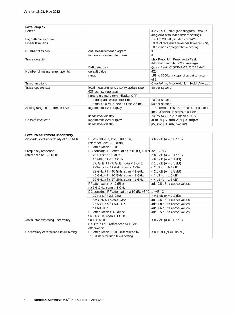
Level display Screen (625 × 500) pixel (one diagram), max. 2
diagrams with independent settings Logarithmic level axis 1 dB to 200 dB, in steps of 1/2/5 Linear level axis 10 % of reference level per level division,
10 divisions or logarithmic scaling Number of traces one measurement diagram 3
two measurement diagrams 6 Trace detector Max Peak, Min Peak, Auto Peak
(Normal), sample, RMS, average, EMI detectors Quasi Peak, CISPR-RMS, CISPR-AV
Number of measurement points default value 625 range 155 to 30001 in steps of about a factor
of 2 Trace functions Clear/Write, Max Hold, Min Hold, Average Trace update rate local measurement, display update rate,
625 points, zero span 80 per second
remote measurement, display OFF zero span/sweep time 1 ms 70 per second span = 10 MHz, sweep time 2.5 ms 50 per second
Setting range of reference level logarithmic level display –130 dBm to (+5 dBm + RF attenuation), max. 30 dBm, in steps of 0.1 dB
linear level display 7.0 nV to 7.07 V in steps of 1 % Units of level axis logarithmic level display dBm, dBµV, dBmV, dBµA, dBpW
linear level display µV, mV, µA, mA, pW, nW
Level measurement uncertainty Absolute level uncertainty at 128 MHz RBW = 10 kHz, level –30 dBm,
reference level –30 dBm, RF attenuation 10 dB
< 0.2 dB (σ = 0.07 dB)
Frequency response referenced to 128 MHz
DC coupling, RF attenuation ≥ 10 dB, +20 °C to +30 °C 20 Hz ≤ f < 10 MHz < 0.5 dB (σ = 0.17 dB) 10 MHz ≤ f < 3.6 GHz < 0.3 dB (σ = 0.1 dB) 3.6 GHz ≤ f < 8 GHz, span < 1 GHz < 1.5 dB (σ = 0.5 dB) 8 GHz ≤ f < 22 GHz, span < 1 GHz < 2 dB (σ = 0.7 dB) 22 GHz ≤ f < 40 GHz, span < 1 GHz < 2.5 dB (σ = 0.8 dB) 40 GHz ≤ f < 50 GHz, span < 1 GHz < 3 dB (σ = 1.0 dB) 50 GHz ≤ f ≤ 67 GHz, span < 1 GHz < 4 dB (σ = 1.3 dB)
RF attenuation > 40 dB or f ≥ 3.6 GHz, span ≥ 1 GHz
add 0.5 dB to above values
DC coupling, RF attenuation ≥ 10 dB, +5 °C to +45 °C 20 Hz ≤ f < 3.6 GHz < 0.6 dB (σ = 0.2 dB) 3.6 GHz ≤ f < 26.5 GHz add 0.5 dB to above values 26.5 GHz ≤ f < 50 GHz add 1.0 dB to above values f ≥ 50 GHz add 1.5 dB to above values
RF attenuation > 40 dB or f ≥ 3.6 GHz, span ≥ 1 GHz
add 0.5 dB to above values
Attenuator switching uncertainty f = 128 MHz 0 dB to 70 dB, referenced to 10 dB attenuation
< 0.2 dB (σ = 0.07 dB)
Uncertainty of reference level setting RF attenuation 10 dB, referenced to –10 dBm reference level setting
< 0.15 dB (σ = 0.05 dB)
Version 16.01, May 2012
Rohde & Schwarz R&S®FSU Spectrum Analyzer 9
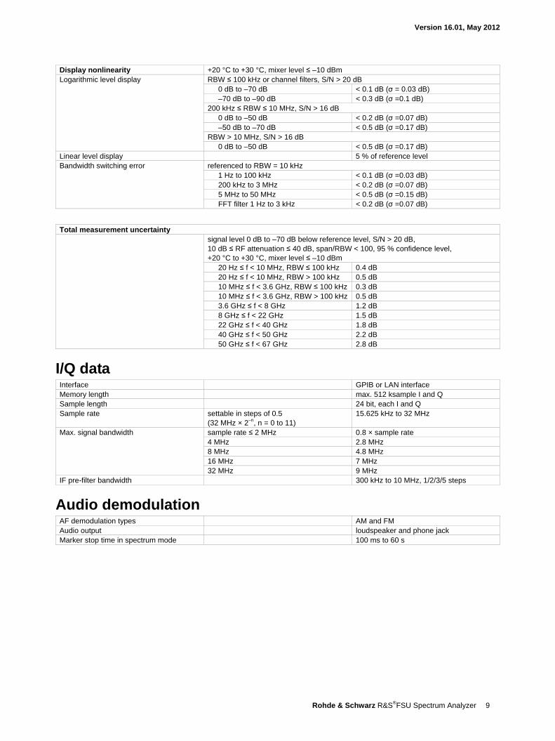
Display nonlinearity +20 °C to +30 °C, mixer level ≤ –10 dBm Logarithmic level display RBW ≤ 100 kHz or channel filters, S/N > 20 dB
0 dB to –70 dB < 0.1 dB (σ = 0.03 dB) –70 dB to –90 dB < 0.3 dB (σ =0.1 dB)
200 kHz ≤ RBW ≤ 10 MHz, S/N > 16 dB 0 dB to –50 dB < 0.2 dB (σ =0.07 dB) –50 dB to –70 dB < 0.5 dB (σ =0.17 dB)
RBW > 10 MHz, S/N > 16 dB 0 dB to –50 dB < 0.5 dB (σ =0.17 dB)
Linear level display 5 % of reference level Bandwidth switching error referenced to RBW = 10 kHz
1 Hz to 100 kHz < 0.1 dB (σ =0.03 dB) 200 kHz to 3 MHz < 0.2 dB (σ =0.07 dB) 5 MHz to 50 MHz < 0.5 dB (σ =0.15 dB) FFT filter 1 Hz to 3 kHz < 0.2 dB (σ =0.07 dB)
Total measurement uncertainty signal level 0 dB to –70 dB below reference level, S/N > 20 dB,
10 dB ≤ RF attenuation ≤ 40 dB, span/RBW < 100, 95 % confidence level, +20 °C to +30 °C, mixer level ≤ –10 dBm
20 Hz ≤ f < 10 MHz, RBW ≤ 100 kHz 0.4 dB 20 Hz ≤ f < 10 MHz, RBW > 100 kHz 0.5 dB 10 MHz ≤ f < 3.6 GHz, RBW ≤ 100 kHz 0.3 dB 10 MHz ≤ f < 3.6 GHz, RBW > 100 kHz 0.5 dB 3.6 GHz ≤ f < 8 GHz 1.2 dB 8 GHz ≤ f < 22 GHz 1.5 dB 22 GHz ≤ f < 40 GHz 1.8 dB 40 GHz ≤ f < 50 GHz 2.2 dB 50 GHz ≤ f < 67 GHz 2.8 dB
I/Q data Interface GPIB or LAN interface Memory length max. 512 ksample I and Q Sample length 24 bit, each I and Q Sample rate settable in steps of 0.5
(32 MHz × 2–n, n = 0 to 11) 15.625 kHz to 32 MHz
Max. signal bandwidth sample rate ≤ 2 MHz 0.8 × sample rate 4 MHz 2.8 MHz 8 MHz 4.8 MHz 16 MHz 7 MHz 32 MHz 9 MHz
IF pre-filter bandwidth 300 kHz to 10 MHz, 1/2/3/5 steps
Audio demodulation AF demodulation types AM and FM Audio output loudspeaker and phone jack Marker stop time in spectrum mode 100 ms to 60 s
Version 16.01, May 2012
10 Rohde & Schwarz R&S®FSU Spectrum Analyzer
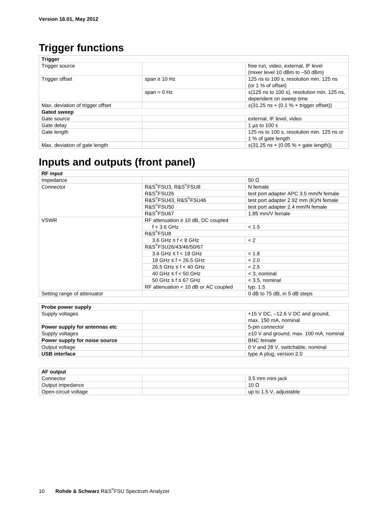
Trigger functions Trigger Trigger source free run, video, external, IF level
(mixer level 10 dBm to –50 dBm) Trigger offset span ≥ 10 Hz 125 ns to 100 s, resolution min. 125 ns
(or 1 % of offset) span = 0 Hz ±(125 ns to 100 s), resolution min. 125 ns,
dependent on sweep time Max. deviation of trigger offset ±(31.25 ns + (0.1 % × trigger offset)) Gated sweep Gate source external, IF level, video Gate delay 1 µs to 100 s Gate length 125 ns to 100 s, resolution min. 125 ns or
1 % of gate length Max. deviation of gate length ±(31.25 ns + (0.05 % × gate length))
Inputs and outputs (front panel) RF input Impedance 50 Ω Connector R&S®FSU3, R&S®FSU8 N female
R&S®FSU26 test port adapter APC 3.5 mm/N female R&S®FSU43, R&S®FSU46 test port adapter 2.92 mm (K)/N female R&S®FSU50 test port adapter 2.4 mm/N female R&S®FSU67 1.85 mm/V female
VSWR RF attenuation ≥ 10 dB, DC coupled f < 3.6 GHz < 1.5
R&S®FSU8 3.6 GHz ≤ f < 8 GHz < 2
R&S®FSU26/43/46/50/67 3.6 GHz ≤ f < 18 GHz < 1.8 18 GHz ≤ f < 26.5 GHz < 2.0 26.5 GHz ≤ f < 40 GHz < 2.5 40 GHz ≤ f < 50 GHz < 3, nominal 50 GHz ≤ f ≤ 67 GHz < 3.5, nominal
RF attenuation < 10 dB or AC coupled typ. 1.5 Setting range of attenuator 0 dB to 75 dB, in 5 dB steps
Probe power supply Supply voltages +15 V DC, –12.6 V DC and ground,
max. 150 mA, nominal Power supply for antennas etc 5-pin connector Supply voltages ±10 V and ground, max. 100 mA, nominal Power supply for noise source BNC female Output voltage 0 V and 28 V, switchable, nominal USB interface type A plug, version 2.0
AF output Connector 3.5 mm mini jack Output impedance 10 Ω Open-circuit voltage up to 1.5 V, adjustable
Version 16.01, May 2012
Rohde & Schwarz R&S®FSU Spectrum Analyzer 11
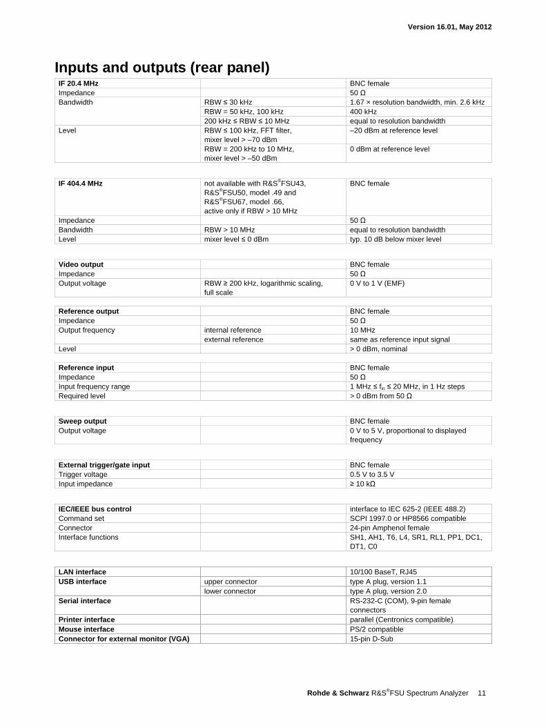
Inputs and outputs (rear panel) IF 20.4 MHz BNC female Impedance 50 Ω Bandwidth RBW ≤ 30 kHz 1.67 × resolution bandwidth, min. 2.6 kHz
RBW = 50 kHz, 100 kHz 400 kHz 200 kHz ≤ RBW ≤ 10 MHz equal to resolution bandwidth
Level RBW ≤ 100 kHz, FFT filter, mixer level > –70 dBm
–20 dBm at reference level
RBW = 200 kHz to 10 MHz, mixer level > –50 dBm
0 dBm at reference level
IF 404.4 MHz not available with R&S®FSU43, R&S®FSU50, model .49 and R&S®FSU67, model .66, active only if RBW > 10 MHz
BNC female
Impedance 50 Ω Bandwidth RBW > 10 MHz equal to resolution bandwidth Level mixer level ≤ 0 dBm typ. 10 dB below mixer level
Video output BNC female Impedance 50 Ω Output voltage RBW ≥ 200 kHz, logarithmic scaling,
full scale 0 V to 1 V (EMF)
Reference output BNC female Impedance 50 Ω Output frequency internal reference 10 MHz
external reference same as reference input signal Level > 0 dBm, nominal
Reference input BNC female Impedance 50 Ω Input frequency range 1 MHz ≤ fin ≤ 20 MHz, in 1 Hz steps Required level > 0 dBm from 50 Ω
Sweep output BNC female Output voltage 0 V to 5 V, proportional to displayed
frequency
External trigger/gate input BNC female Trigger voltage 0.5 V to 3.5 V Input impedance ≥ 10 kΩ
IEC/IEEE bus control interface to IEC 625-2 (IEEE 488.2) Command set SCPI 1997.0 or HP8566 compatible Connector 24-pin Amphenol female Interface functions SH1, AH1, T6, L4, SR1, RL1, PP1, DC1,
DT1, C0
LAN interface 10/100 BaseT, RJ45 USB interface upper connector type A plug, version 1.1
lower connector type A plug, version 2.0 Serial interface RS-232-C (COM), 9-pin female
connectors Printer interface parallel (Centronics compatible) Mouse interface PS/2 compatible Connector for external monitor (VGA) 15-pin D-Sub
Version 16.01, May 2012
12 Rohde & Schwarz R&S®FSU Spectrum Analyzer
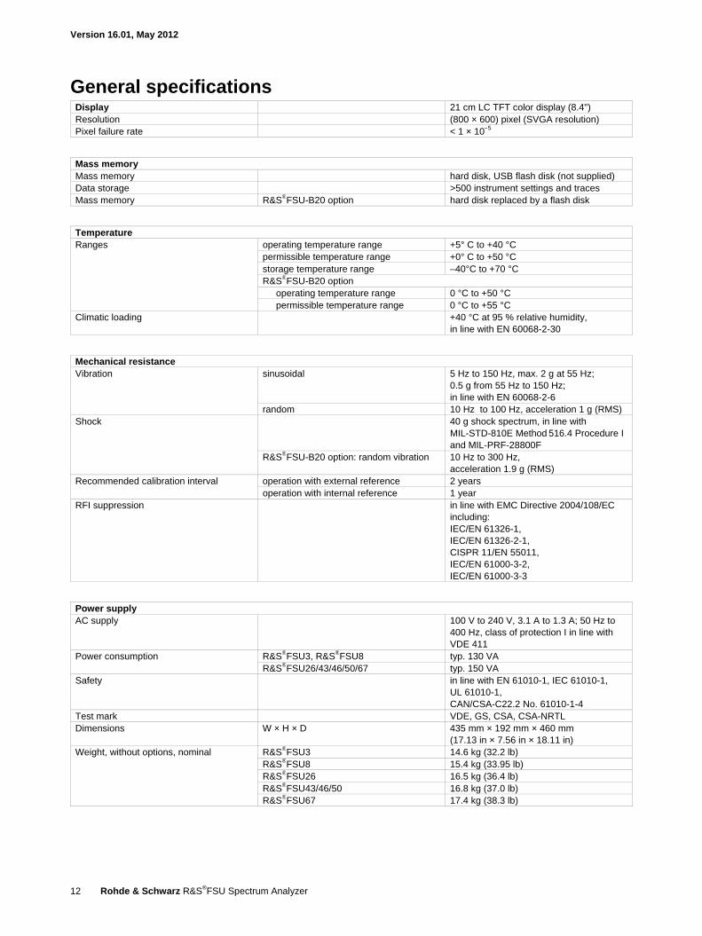
General specifications Display 21 cm LC TFT color display (8.4") Resolution (800 × 600) pixel (SVGA resolution) Pixel failure rate < 1 × 10⁻⁵
Mass memory Mass memory hard disk, USB flash disk (not supplied) Data storage >500 instrument settings and traces Mass memory R&S®FSU-B20 option hard disk replaced by a flash disk
Temperature Ranges operating temperature range +5° C to +40 °C
permissible temperature range +0° C to +50 °C storage temperature range –40°C to +70 °C R&S®FSU-B20 option
operating temperature range 0 °C to +50 °C permissible temperature range 0 °C to +55 °C
Climatic loading +40 °C at 95 % relative humidity, in line with EN 60068-2-30
Mechanical resistance Vibration sinusoidal 5 Hz to 150 Hz, max. 2 g at 55 Hz;
0.5 g from 55 Hz to 150 Hz; in line with EN 60068-2-6
random 10 Hz to 100 Hz, acceleration 1 g (RMS) Shock 40 g shock spectrum, in line with
MIL-STD-810E Method 516.4 Procedure I and MIL-PRF-28800F
R&S®FSU-B20 option: random vibration 10 Hz to 300 Hz, acceleration 1.9 g (RMS)
Recommended calibration interval operation with external reference 2 years operation with internal reference 1 year
RFI suppression in line with EMC Directive 2004/108/EC including: IEC/EN 61326-1, IEC/EN 61326-2-1, CISPR 11/EN 55011, IEC/EN 61000-3-2, IEC/EN 61000-3-3
Power supply AC supply 100 V to 240 V, 3.1 A to 1.3 A; 50 Hz to
400 Hz, class of protection I in line with VDE 411
Power consumption R&S®FSU3, R&S®FSU8 typ. 130 VA R&S®FSU26/43/46/50/67 typ. 150 VA
Safety in line with EN 61010-1, IEC 61010-1, UL 61010-1, CAN/CSA-C22.2 No. 61010-1-4
Test mark VDE, GS, CSA, CSA-NRTL Dimensions W × H × D 435 mm × 192 mm × 460 mm
(17.13 in × 7.56 in × 18.11 in) Weight, without options, nominal R&S®FSU3 14.6 kg (32.2 lb)
R&S®FSU8 15.4 kg (33.95 lb) R&S®FSU26 16.5 kg (36.4 lb) R&S®FSU43/46/50 16.8 kg (37.0 lb) R&S®FSU67 17.4 kg (38.3 lb)
Version 16.01, May 2012
Rohde & Schwarz R&S®FSU Spectrum Analyzer 13
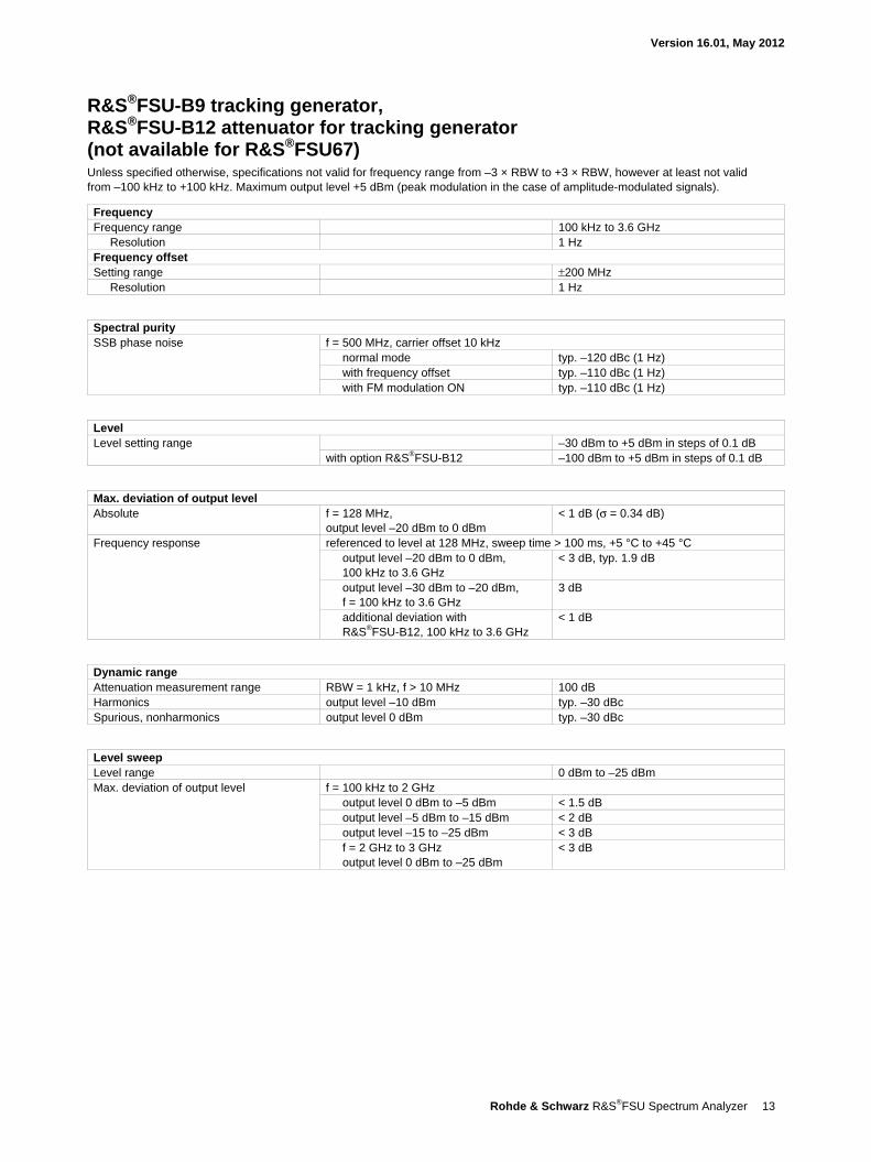
R&S®FSU-B9 tracking generator, R&S®FSU-B12 attenuator for tracking generator (not available for R&S®FSU67) Unless specified otherwise, specifications not valid for frequency range from –3 × RBW to +3 × RBW, however at least not valid from –100 kHz to +100 kHz. Maximum output level +5 dBm (peak modulation in the case of amplitude-modulated signals).
Frequency Frequency range 100 kHz to 3.6 GHz
Resolution 1 Hz Frequency offset Setting range ±200 MHz
Resolution 1 Hz
Spectral purity SSB phase noise f = 500 MHz, carrier offset 10 kHz
normal mode typ. –120 dBc (1 Hz) with frequency offset typ. –110 dBc (1 Hz) with FM modulation ON typ. –110 dBc (1 Hz)
Level Level setting range –30 dBm to +5 dBm in steps of 0.1 dB
with option R&S®FSU-B12 –100 dBm to +5 dBm in steps of 0.1 dB
Max. deviation of output level Absolute f = 128 MHz,
output level –20 dBm to 0 dBm < 1 dB (σ = 0.34 dB)
Frequency response referenced to level at 128 MHz, sweep time > 100 ms, +5 °C to +45 °C output level –20 dBm to 0 dBm, 100 kHz to 3.6 GHz
< 3 dB, typ. 1.9 dB
output level –30 dBm to –20 dBm, f = 100 kHz to 3.6 GHz
3 dB
additional deviation with R&S®FSU-B12, 100 kHz to 3.6 GHz
< 1 dB
Dynamic range Attenuation measurement range RBW = 1 kHz, f > 10 MHz 100 dB Harmonics output level –10 dBm typ. –30 dBc Spurious, nonharmonics output level 0 dBm typ. –30 dBc
Level sweep Level range 0 dBm to –25 dBm Max. deviation of output level f = 100 kHz to 2 GHz
output level 0 dBm to –5 dBm < 1.5 dB output level –5 dBm to –15 dBm < 2 dB output level –15 to –25 dBm < 3 dB f = 2 GHz to 3 GHz output level 0 dBm to –25 dBm
< 3 dB
Version 16.01, May 2012
14 Rohde & Schwarz R&S®FSU Spectrum Analyzer
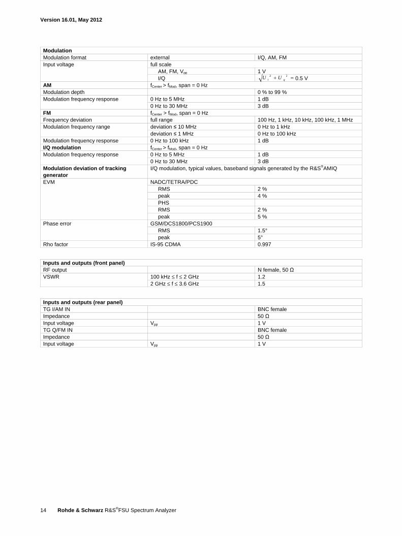
Modulation Modulation format external I/Q, AM, FM Input voltage full scale
AM, FM, Vpp 1 V I/Q =+ 22
qi UU 0.5 V AM fCenter > fMod, span = 0 Hz Modulation depth 0 % to 99 % Modulation frequency response 0 Hz to 5 MHz 1 dB
0 Hz to 30 MHz 3 dB FM fCenter > fMod, span = 0 Hz Frequency deviation full range 100 Hz, 1 kHz, 10 kHz, 100 kHz, 1 MHz Modulation frequency range deviation ≤ 10 MHz 0 Hz to 1 kHz
deviation ≤ 1 MHz 0 Hz to 100 kHz Modulation frequency response 0 Hz to 100 kHz 1 dB I/Q modulation fCenter > fMod, span = 0 Hz Modulation frequency response 0 Hz to 5 MHz 1 dB
0 Hz to 30 MHz 3 dB Modulation deviation of tracking generator
I/Q modulation, typical values, baseband signals generated by the R&S®AMIQ
EVM NADC/TETRA/PDC RMS 2 % peak 4 % PHS RMS 2 % peak 5 %
Phase error GSM/DCS1800/PCS1900 RMS 1.5° peak 5°
Rho factor IS-95 CDMA 0.997
Inputs and outputs (front panel) RF output N female, 50 Ω VSWR 100 kHz ≤ f ≤ 2 GHz 1.2
2 GHz ≤ f ≤ 3.6 GHz 1.5
Inputs and outputs (rear panel) TG I/AM IN BNC female Impedance 50 Ω Input voltage Vpp 1 V TG Q/FM IN BNC female Impedance 50 Ω Input voltage Vpp 1 V
Version 16.01, May 2012
Rohde & Schwarz R&S®FSU Spectrum Analyzer 15
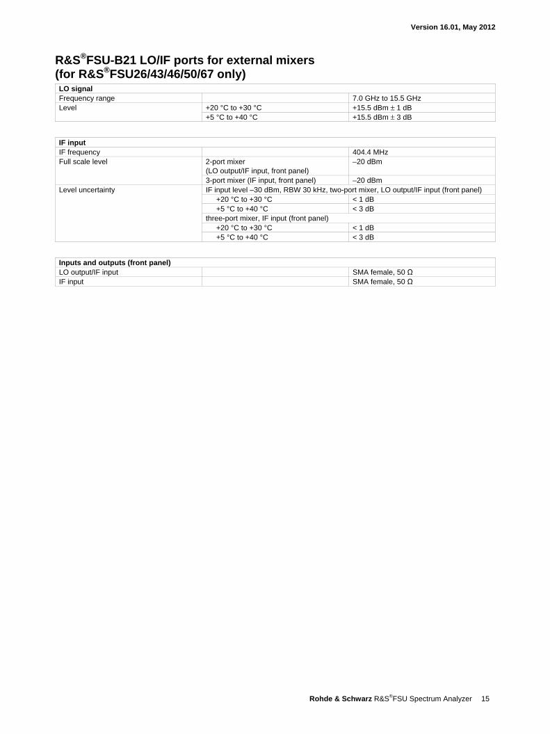
R&S®FSU-B21 LO/IF ports for external mixers (for R&S®FSU26/43/46/50/67 only) LO signal Frequency range 7.0 GHz to 15.5 GHz Level +20 °C to +30 °C +15.5 dBm ± 1 dB
+5 °C to +40 °C +15.5 dBm ± 3 dB
IF input IF frequency 404.4 MHz Full scale level 2-port mixer
(LO output/IF input, front panel) –20 dBm
3-port mixer (IF input, front panel) –20 dBm Level uncertainty IF input level –30 dBm, RBW 30 kHz, two-port mixer, LO output/IF input (front panel)
+20 °C to +30 °C < 1 dB +5 °C to +40 °C < 3 dB
three-port mixer, IF input (front panel) +20 °C to +30 °C < 1 dB +5 °C to +40 °C < 3 dB
Inputs and outputs (front panel) LO output/IF input SMA female, 50 Ω IF input SMA female, 50 Ω
Version 16.01, May 2012
16 Rohde & Schwarz R&S®FSU Spectrum Analyzer
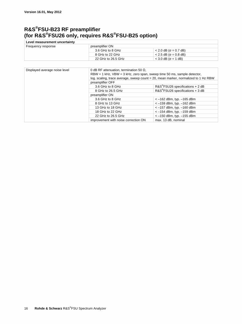
R&S®FSU-B23 RF preamplifier (for R&S®FSU26 only, requires R&S®FSU-B25 option) Level measurement uncertainty Frequency response preamplifier ON
3.6 GHz to 8 GHz < 2.0 dB (σ = 0.7 dB) 8 GHz to 22 GHz < 2.5 dB (σ = 0.8 dB) 22 GHz to 26.5 GHz < 3.0 dB (σ = 1 dB)
Displayed average noise level 0 dB RF attenuation, termination 50 Ω, RBW = 1 kHz, VBW = 3 kHz, zero span, sweep time 50 ms, sample detector, log. scaling, trace average, sweep count = 20, mean marker, normalized to 1 Hz RBW preamplifier OFF
3.6 GHz to 8 GHz R&S®FSU26 specifications + 2 dB 8 GHz to 26.5 GHz R&S®FSU26 specifications + 3 dB
preamplifier ON 3.6 GHz to 8 GHz < –162 dBm, typ. –165 dBm 8 GHz to 13 GHz < –159 dBm, typ. –162 dBm 13 GHz to 18 GHz < –157 dBm, typ. –160 dBm 18 GHz to 22 GHz < –154 dBm, typ. –159 dBm 22 GHz to 26.5 GHz < –150 dBm, typ. –155 dBm
improvement with noise correction ON max. 13 dB, nominal
Version 16.01, May 2012
Rohde & Schwarz R&S®FSU Spectrum Analyzer 17
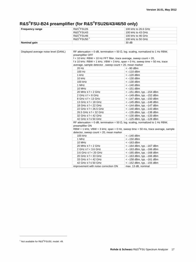
R&S®FSU-B24 preamplifier (for R&S®FSU26/43/46/50 only) Frequency range R&S®FSU26 100 kHz to 26.6 GHz
R&S®FSU43 100 kHz to 43 GHz R&S®FSU46 100 kHz to 46 GHz R&S®FSU50 1 100 kHz to 50 GHz
Nominal gain 30 dB
Displayed average noise level (DANL) RF attenuation = 0 dB, termination = 50 Ω, log. scaling, normalized to 1 Hz RBW, preamplifier OFF f < 10 kHz: RBW = 10 Hz FFT filter, trace average, sweep count = 20, f ≥ 10 kHz: RBW = 1 kHz, VBW = 3 kHz, span = 0 Hz, sweep time = 50 ms, trace average, sample detector , sweep count = 20, mean marker
20 Hz < –90 dBm 100 Hz < –110 dBm 1 kHz < –120 dBm 10 kHz < –130 dBm 100 kHz < –130 dBm 1 MHz < –140 dBm 10 MHz < –151 dBm 20 MHz ≤ f < 2 GHz < –151 dBm, typ. –154 dBm 2 GHz ≤ f < 8 GHz < –149 dBm, typ. –152 dBm 8 GHz ≤ f < 13 GHz < –147 dBm, typ. –150 dBm 13 GHz ≤ f < 18 GHz < –145 dBm, typ. –148 dBm 18 GHz ≤ f < 22 GHz < –144 dBm, typ. –147 dBm 22 GHz ≤ f < 26.5 GHz < –140 dBm, typ. –143 dBm 26.5 GHz ≤ f < 32 GHz < –135 dBm, typ. –138 dBm 32 GHz ≤ f < 42 GHz < –130 dBm, typ. –133 dBm 42 GHz ≤ f ≤ 50 GHz < –125 dBm, typ. –128 dBm
RF attenuation = 0 dB, termination = 50 Ω, log. scaling, normalized to 1 Hz RBW, preamplifier ON RBW = 1 kHz, VBW = 3 kHz, span = 0 Hz, sweep time = 50 ms, trace average, sample detector, sweep count = 20, mean marker
100 kHz < –140 dBm 1 MHz < –150 dBm 10 MHz < –163 dBm 20 MHz ≤ f < 2 GHz < –164 dBm, typ. –167 dBm 2 GHz ≤ f < 3.6 GHz < –163 dBm, typ. –166 dBm 3.6 GHz ≤ f < 20 GHz < –165 dBm, typ. –168 dBm 20 GHz ≤ f < 33 GHz < –163 dBm, typ. –166 dBm 33 GHz ≤ f < 42 GHz < –158 dBm, typ. –161 dBm 42 GHz ≤ f ≤ 50 GHz < –152 dBm, typ. –155 dBm
improvement with noise correction ON max. 13 dB, nominal
1 Not available for R&S®FSU50, model .49.
Version 16.01, May 2012
18 Rohde & Schwarz R&S®FSU Spectrum Analyzer
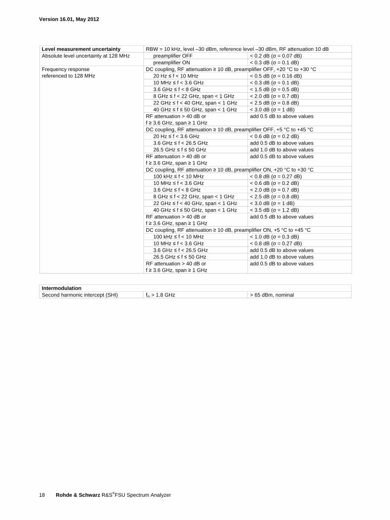
Level measurement uncertainty RBW = 10 kHz, level –30 dBm, reference level –30 dBm, RF attenuation 10 dB Absolute level uncertainty at 128 MHz preamplifier OFF < 0.2 dB (σ = 0.07 dB)
preamplifier ON < 0.3 dB (σ = 0.1 dB) Frequency response referenced to 128 MHz
DC coupling, RF attenuation ≥ 10 dB, preamplifier OFF, +20 °C to +30 °C 20 Hz ≤ f < 10 MHz < 0.5 dB (σ = 0.16 dB) 10 MHz ≤ f < 3.6 GHz < 0.3 dB (σ = 0.1 dB) 3.6 GHz ≤ f < 8 GHz < 1.5 dB (σ = 0.5 dB) 8 GHz ≤ f < 22 GHz, span < 1 GHz < 2.0 dB (σ = 0.7 dB) 22 GHz ≤ f < 40 GHz, span < 1 GHz < 2.5 dB (σ = 0.8 dB) 40 GHz ≤ f ≤ 50 GHz, span < 1 GHz < 3.0 dB (σ = 1 dB)
RF attenuation > 40 dB or f ≥ 3.6 GHz, span ≥ 1 GHz
add 0.5 dB to above values
DC coupling, RF attenuation ≥ 10 dB, preamplifier OFF, +5 °C to +45 °C 20 Hz ≤ f < 3.6 GHz < 0.6 dB (σ = 0.2 dB) 3.6 GHz ≤ f < 26.5 GHz add 0.5 dB to above values 26.5 GHz ≤ f ≤ 50 GHz add 1.0 dB to above values
RF attenuation > 40 dB or f ≥ 3.6 GHz, span ≥ 1 GHz
add 0.5 dB to above values
DC coupling, RF attenuation ≥ 10 dB, preamplifier ON, +20 °C to +30 °C 100 kHz ≤ f < 10 MHz < 0.8 dB (σ = 0.27 dB) 10 MHz ≤ f < 3.6 GHz < 0.6 dB (σ = 0.2 dB) 3.6 GHz ≤ f < 8 GHz < 2.0 dB (σ = 0.7 dB) 8 GHz ≤ f < 22 GHz, span < 1 GHz < 2.5 dB (σ = 0.8 dB) 22 GHz ≤ f < 40 GHz, span < 1 GHz < 3.0 dB (σ = 1 dB) 40 GHz ≤ f ≤ 50 GHz, span < 1 GHz < 3.5 dB (σ = 1.2 dB)
RF attenuation > 40 dB or f ≥ 3.6 GHz, span ≥ 1 GHz
add 0.5 dB to above values
DC coupling, RF attenuation ≥ 10 dB, preamplifier ON, +5 °C to +45 °C 100 kHz ≤ f < 10 MHz < 1.0 dB (σ = 0.3 dB) 10 MHz ≤ f < 3.6 GHz < 0.8 dB (σ = 0.27 dB) 3.6 GHz ≤ f < 26.5 GHz add 0.5 dB to above values 26.5 GHz ≤ f ≤ 50 GHz add 1.0 dB to above values
RF attenuation > 40 dB or f ≥ 3.6 GHz, span ≥ 1 GHz
add 0.5 dB to above values
Intermodulation Second harmonic intercept (SHI) fin > 1.8 GHz > 65 dBm, nominal
Version 16.01, May 2012
Rohde & Schwarz R&S®FSU Spectrum Analyzer 19
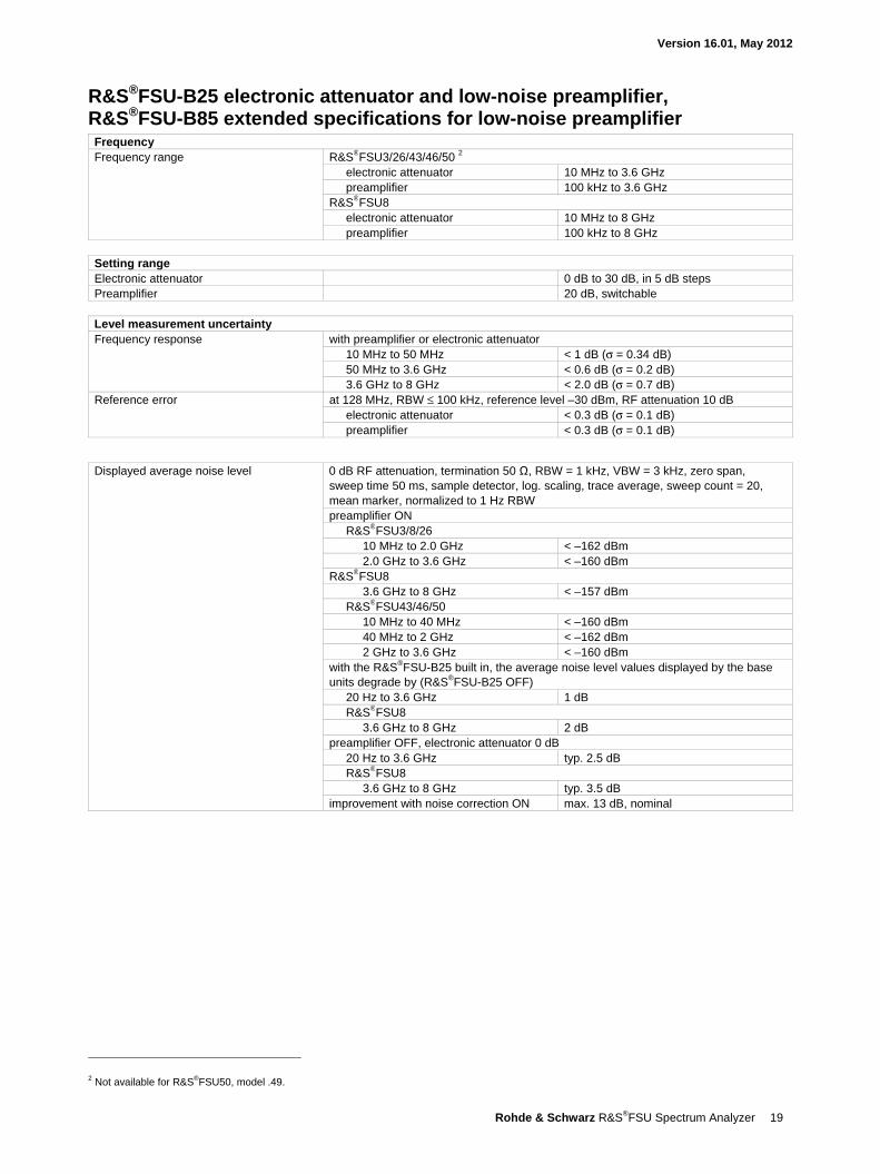
R&S®FSU-B25 electronic attenuator and low-noise preamplifier, R&S®FSU-B85 extended specifications for low-noise preamplifier Frequency Frequency range R&S®FSU3/26/43/46/50 2
electronic attenuator 10 MHz to 3.6 GHz preamplifier 100 kHz to 3.6 GHz
R&S®FSU8 electronic attenuator 10 MHz to 8 GHz preamplifier 100 kHz to 8 GHz
Setting range Electronic attenuator 0 dB to 30 dB, in 5 dB steps Preamplifier 20 dB, switchable
Level measurement uncertainty Frequency response with preamplifier or electronic attenuator
10 MHz to 50 MHz < 1 dB (σ = 0.34 dB) 50 MHz to 3.6 GHz < 0.6 dB (σ = 0.2 dB) 3.6 GHz to 8 GHz < 2.0 dB (σ = 0.7 dB)
Reference error at 128 MHz, RBW ≤ 100 kHz, reference level –30 dBm, RF attenuation 10 dB electronic attenuator < 0.3 dB (σ = 0.1 dB) preamplifier < 0.3 dB (σ = 0.1 dB)
Displayed average noise level 0 dB RF attenuation, termination 50 Ω, RBW = 1 kHz, VBW = 3 kHz, zero span, sweep time 50 ms, sample detector, log. scaling, trace average, sweep count = 20, mean marker, normalized to 1 Hz RBW preamplifier ON
R&S®FSU3/8/26 10 MHz to 2.0 GHz < –162 dBm 2.0 GHz to 3.6 GHz < –160 dBm
R&S®FSU8 3.6 GHz to 8 GHz < –157 dBm
R&S®FSU43/46/50 10 MHz to 40 MHz < –160 dBm 40 MHz to 2 GHz < –162 dBm 2 GHz to 3.6 GHz < –160 dBm
with the R&S®FSU-B25 built in, the average noise level values displayed by the base units degrade by (R&S®FSU-B25 OFF)
20 Hz to 3.6 GHz 1 dB R&S®FSU8
3.6 GHz to 8 GHz 2 dB preamplifier OFF, electronic attenuator 0 dB
20 Hz to 3.6 GHz typ. 2.5 dB R&S®FSU8
3.6 GHz to 8 GHz typ. 3.5 dB improvement with noise correction ON max. 13 dB, nominal
2 Not available for R&S®FSU50, model .49.
Version 16.01, May 2012
20 Rohde & Schwarz R&S®FSU Spectrum Analyzer
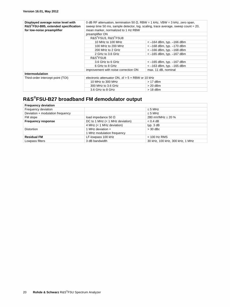
Displayed average noise level with R&S®FSU-B85, extended specification for low-noise preamplifier
0 dB RF attenuation, termination 50 Ω, RBW = 1 kHz, VBW = 3 kHz, zero span, sweep time 50 ms, sample detector, log. scaling, trace average, sweep count = 20, mean marker, normalized to 1 Hz RBW preamplifier ON
R&S®FSU3, R&S®FSU8 10 MHz to 100 MHz < –164 dBm, typ. –166 dBm 100 MHz to 200 MHz < –168 dBm, typ. –170 dBm 200 MHz to 2 GHz < –166 dBm, typ. –168 dBm 2 GHz to 3.6 GHz < –165 dBm, typ. –167 dBm
R&S®FSU8 3.6 GHz to 6 GHz < –165 dBm, typ. –167 dBm 6 GHz to 8 GHz < –163 dBm, typ. –165 dBm
improvement with noise correction ON max. 11 dB, nominal Intermodulation Third-order intercept point (TOI) electronic attenuator ON, Δf > 5 × RBW or 10 kHz
10 MHz to 300 MHz > 17 dBm 300 MHz to 3.6 GHz > 20 dBm 3.6 GHz to 8 GHz > 18 dBm
R&S®FSU-B27 broadband FM demodulator output Frequency deviation Frequency deviation ≤ 5 MHz Deviation + modulation frequency ≤ 5 MHz FM slope load impedance 50 Ω 280 mV/MHz ± 20 % Frequency response DC to 1 MHz (< 1 MHz deviation) < 0.4 dB
4 MHz (< 1 MHz deviation) typ. 3 dB Distortion 1 MHz deviation +
1 MHz modulation frequency > 30 dBc
Residual FM LF-lowpass 100 kHz < 100 Hz RMS Lowpass filters 3 dB bandwidth 30 kHz, 100 kHz, 300 kHz, 1 MHz
Version 16.01, May 2012
Rohde & Schwarz R&S®FSU Spectrum Analyzer 21
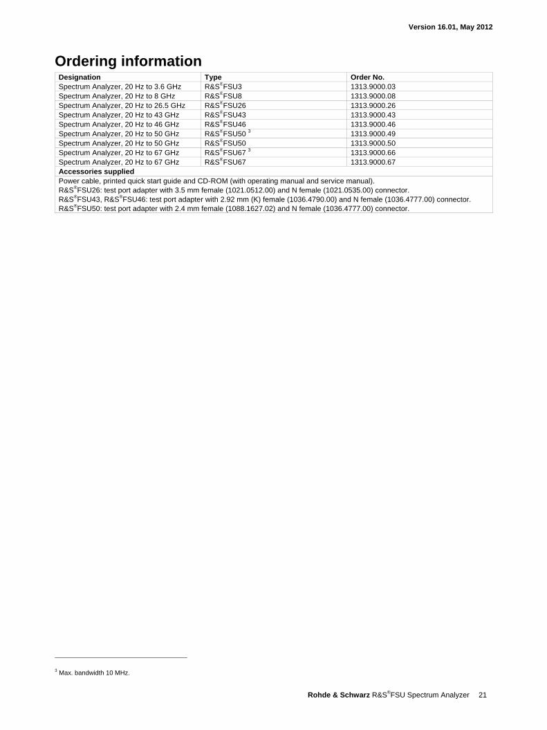
Ordering information Designation Type Order No. Spectrum Analyzer, 20 Hz to 3.6 GHz R&S®FSU3 1313.9000.03 Spectrum Analyzer, 20 Hz to 8 GHz R&S®FSU8 1313.9000.08 Spectrum Analyzer, 20 Hz to 26.5 GHz R&S®FSU26 1313.9000.26 Spectrum Analyzer, 20 Hz to 43 GHz R&S®FSU43 1313.9000.43 Spectrum Analyzer, 20 Hz to 46 GHz R&S®FSU46 1313.9000.46 Spectrum Analyzer, 20 Hz to 50 GHz R&S®FSU50 3 1313.9000.49 Spectrum Analyzer, 20 Hz to 50 GHz R&S®FSU50 1313.9000.50 Spectrum Analyzer, 20 Hz to 67 GHz R&S®FSU67 3 1313.9000.66 Spectrum Analyzer, 20 Hz to 67 GHz R&S®FSU67 1313.9000.67 Accessories supplied Power cable, printed quick start guide and CD-ROM (with operating manual and service manual). R&S®FSU26: test port adapter with 3.5 mm female (1021.0512.00) and N female (1021.0535.00) connector. R&S®FSU43, R&S®FSU46: test port adapter with 2.92 mm (K) female (1036.4790.00) and N female (1036.4777.00) connector. R&S®FSU50: test port adapter with 2.4 mm female (1088.1627.02) and N female (1036.4777.00) connector.
3 Max. bandwidth 10 MHz.
Version 16.01, May 2012
22 Rohde & Schwarz R&S®FSU Spectrum Analyzer
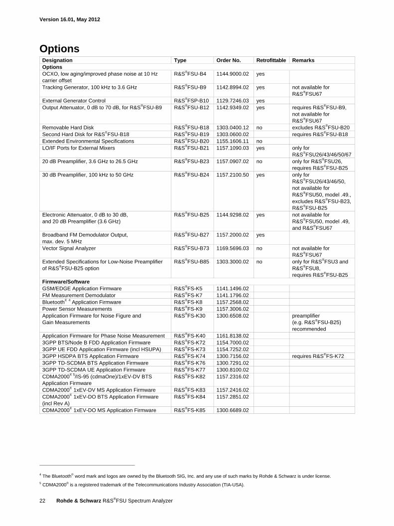
Options Designation Type Order No. Retrofittable Remarks Options OCXO, low aging/improved phase noise at 10 Hz carrier offset
R&S®FSU-B4 1144.9000.02 yes
Tracking Generator, 100 kHz to 3.6 GHz R&S®FSU-B9 1142.8994.02 yes not available for R&S®FSU67
External Generator Control R&S®FSP-B10 1129.7246.03 yes Output Attenuator, 0 dB to 70 dB, for R&S®FSU-B9 R&S®FSU-B12 1142.9349.02 yes requires R&S®FSU-B9,
not available for R&S®FSU67
Removable Hard Disk R&S®FSU-B18 1303.0400.12 no excludes R&S®FSU-B20 Second Hard Disk for R&S®FSU-B18 R&S®FSU-B19 1303.0600.02 requires R&S®FSU-B18 Extended Environmental Specifications R&S®FSU-B20 1155.1606.11 no LO/IF Ports for External Mixers R&S®FSU-B21 1157.1090.03 yes only for
R&S®FSU26/43/46/50/67 20 dB Preamplifier, 3.6 GHz to 26.5 GHz R&S®FSU-B23 1157.0907.02 no only for R&S®FSU26,
requires R&S®FSU-B25 30 dB Preamplifier, 100 kHz to 50 GHz R&S®FSU-B24 1157.2100.50 yes only for
R&S®FSU26/43/46/50, not available for R&S®FSU50, model .49.,excludes R&S®FSU-B23, R&S®FSU-B25
Electronic Attenuator, 0 dB to 30 dB, and 20 dB Preamplifier (3.6 GHz)
R&S®FSU-B25 1144.9298.02 yes not available for R&S®FSU50, model .49, and R&S®FSU67
Broadband FM Demodulator Output, max. dev. 5 MHz
R&S®FSU-B27 1157.2000.02 yes
Vector Signal Analyzer R&S®FSU-B73 1169.5696.03 no not available for R&S®FSU67
Extended Specifications for Low-Noise Preamplifier of R&S®FSU-B25 option
R&S®FSU-B85 1303.3000.02 no only for R&S®FSU3 and R&S®FSU8, requires R&S®FSU-B25
Firmware/Software GSM/EDGE Application Firmware R&S®FS-K5 1141.1496.02 FM Measurement Demodulator R&S®FS-K7 1141.1796.02 Bluetooth® 4 Application Firmware R&S®FS-K8 1157.2568.02 Power Sensor Measurements R&S®FS-K9 1157.3006.02 Application Firmware for Noise Figure and Gain Measurements
R&S®FS-K30 1300.6508.02 preamplifier (e.g. R&S®FSU-B25) recommended
Application Firmware for Phase Noise Measurement R&S®FS-K40 1161.8138.02 3GPP BTS/Node B FDD Application Firmware R&S®FS-K72 1154.7000.02 3GPP UE FDD Application Firmware (incl HSUPA) R&S®FS-K73 1154.7252.02 3GPP HSDPA BTS Application Firmware R&S®FS-K74 1300.7156.02 requires R&S®FS-K72 3GPP TD-SCDMA BTS Application Firmware R&S®FS-K76 1300.7291.02 3GPP TD-SCDMA UE Application Firmware R&S®FS-K77 1300.8100.02 CDMA2000® 5/IS-95 (cdmaOne)/1xEV-DV BTS Application Firmware
R&S®FS-K82 1157.2316.02
CDMA2000® 1xEV-DV MS Application Firmware R&S®FS-K83 1157.2416.02 CDMA2000® 1xEV-DO BTS Application Firmware (incl Rev A)
R&S®FS-K84 1157.2851.02
CDMA2000® 1xEV-DO MS Application Firmware R&S®FS-K85 1300.6689.02
4 The Bluetooth® word mark and logos are owned by the Bluetooth SIG, Inc. and any use of such marks by Rohde & Schwarz is under license. 5 CDMA2000® is a registered trademark of the Telecommunications Industry Association (TIA-USA).
Version 16.01, May 2012
Rohde & Schwarz R&S®FSU Spectrum Analyzer 23
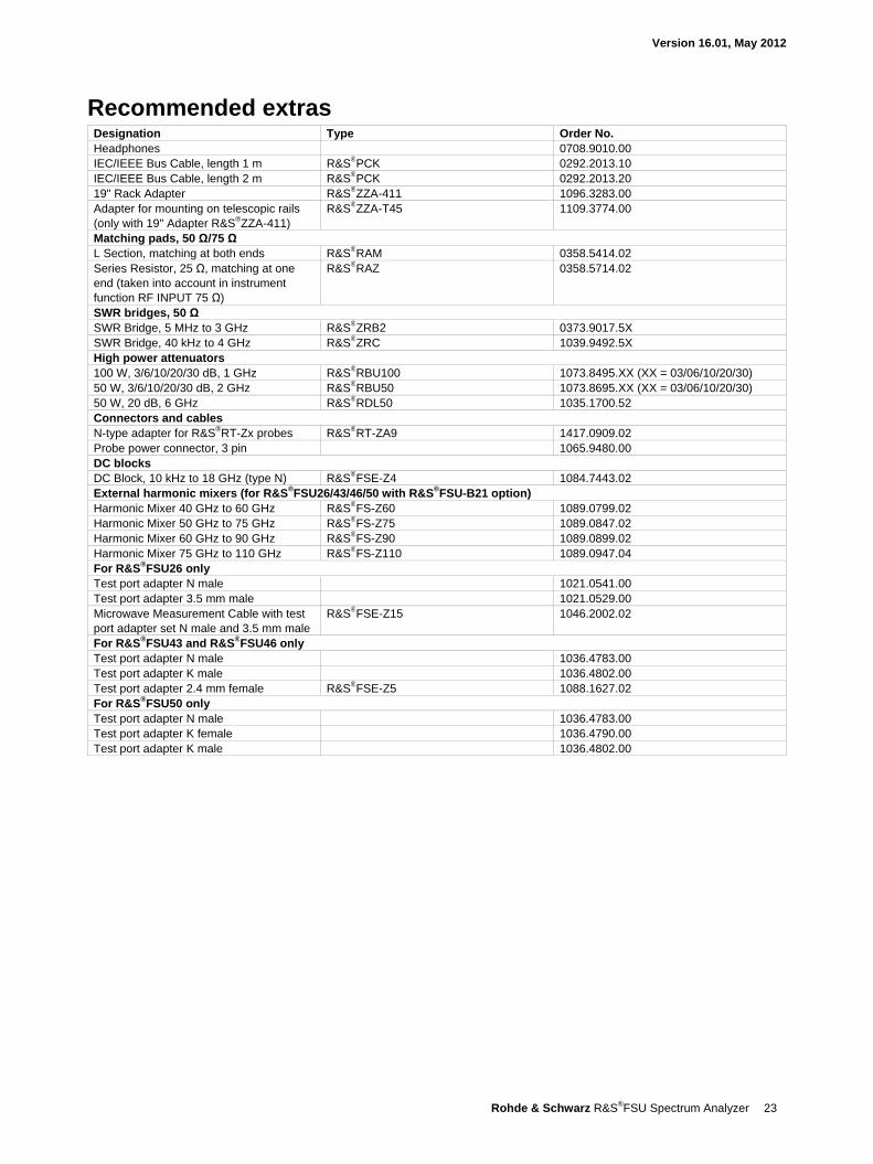
Recommended extras Designation Type Order No. Headphones 0708.9010.00 IEC/IEEE Bus Cable, length 1 m R&S®PCK 0292.2013.10 IEC/IEEE Bus Cable, length 2 m R&S®PCK 0292.2013.20 19" Rack Adapter R&S®ZZA-411 1096.3283.00 Adapter for mounting on telescopic rails (only with 19" Adapter R&S®ZZA-411)
R&S®ZZA-T45 1109.3774.00
Matching pads, 50 Ω/75 Ω L Section, matching at both ends R&S®RAM 0358.5414.02 Series Resistor, 25 Ω, matching at one end (taken into account in instrument function RF INPUT 75 Ω)
R&S®RAZ 0358.5714.02
SWR bridges, 50 Ω SWR Bridge, 5 MHz to 3 GHz R&S®ZRB2 0373.9017.5X SWR Bridge, 40 kHz to 4 GHz R&S®ZRC 1039.9492.5X High power attenuators 100 W, 3/6/10/20/30 dB, 1 GHz R&S®RBU100 1073.8495.XX (XX = 03/06/10/20/30) 50 W, 3/6/10/20/30 dB, 2 GHz R&S®RBU50 1073.8695.XX (XX = 03/06/10/20/30) 50 W, 20 dB, 6 GHz R&S®RDL50 1035.1700.52 Connectors and cables N-type adapter for R&S®RT-Zx probes R&S®RT-ZA9 1417.0909.02 Probe power connector, 3 pin 1065.9480.00 DC blocks DC Block, 10 kHz to 18 GHz (type N) R&S®FSE-Z4 1084.7443.02 External harmonic mixers (for R&S®FSU26/43/46/50 with R&S®FSU-B21 option) Harmonic Mixer 40 GHz to 60 GHz R&S®FS-Z60 1089.0799.02 Harmonic Mixer 50 GHz to 75 GHz R&S®FS-Z75 1089.0847.02 Harmonic Mixer 60 GHz to 90 GHz R&S®FS-Z90 1089.0899.02 Harmonic Mixer 75 GHz to 110 GHz R&S®FS-Z110 1089.0947.04 For R&S®FSU26 only Test port adapter N male 1021.0541.00 Test port adapter 3.5 mm male 1021.0529.00 Microwave Measurement Cable with test port adapter set N male and 3.5 mm male
R&S®FSE-Z15 1046.2002.02
For R&S®FSU43 and R&S®FSU46 only Test port adapter N male 1036.4783.00 Test port adapter K male 1036.4802.00 Test port adapter 2.4 mm female R&S®FSE-Z5 1088.1627.02 For R&S®FSU50 only Test port adapter N male 1036.4783.00 Test port adapter K female 1036.4790.00 Test port adapter K male 1036.4802.00
R&S® is a registered trademark of Rohde & Schwarz GmbH & Co. KG
Trade names are trademarks of the owners | Printed in Germany (as)
PD 0758.0016.22 | Version 16.01 | May 2012 | R&S®FSU
Subject to change
© 2004 -2012 Rohde & Schwarz GmbH & Co. KG | 81671 München, Germany
About Rohde & SchwarzRohde & Schwarz is an independent group of companies specializing in electronics. It is a leading supplier of solu-tions in the fields of test and measurement, broadcasting, radiomonitoring and radiolocation, as well as secure communications. Established more than 75 years ago, Rohde & Schwarz has a global presence and a dedicated service network in over 70 countries. Company headquar-ters are in Munich, Germany.
Certified Quality System
ISO 9001
Regional contact Europe, Africa, Middle East | +49 89 4129 12345 [email protected]
North America | 1 888 TEST RSA (1 888 837 87 72) [email protected]
Latin America | +1 410 910 79 88 [email protected]
Asia/Pacific | +65 65 13 04 88 [email protected]
China | +86 800 810 8228/+86 400 650 5896 [email protected]
Rohde & Schwarz GmbH & Co. KGwww.rohde-schwarz.com
Environmental commitment Energy-efficient products Continuous improvement in environmental sustainability ISO 14001-certified environmental management system
Service you can rely on Worldwide Local and personalized Customized and flexible Uncompromising quality Long-term dependability
0758001622
FSU_dat-sw_en_0758-0016-22_v1601_cover.indd 2 22.05.2012 18:35:42