Embed Size (px)
Citation preview

Br
oadc
astin
g
Prod
uct B
roch
ure
| 03.
00
R&S®CLGCable Load GeneratorSimulation of analog and digital cable TV networks with full channel loading
CLG_bro_en_5214-6416-12.indd 1 18.07.2014 15:15:14
2
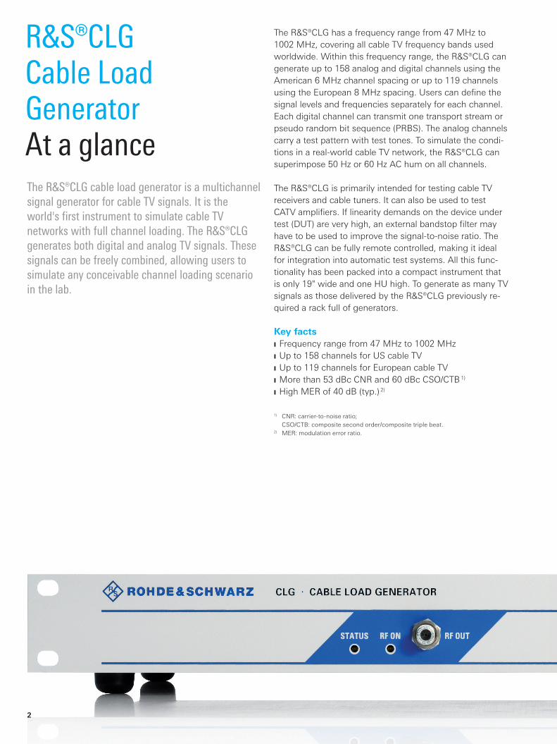
R&S®CLG Cable Load GeneratorAt a glanceThe R&S®CLG cable load generator is a multichannel signal generator for cable TV signals. It is the world's first instrument to simulate cable TV networks with full channel loading. The R&S®CLG generates both digital and analog TV signals. These signals can be freely combined, allowing users to simulate any conceivable channel loading scenario in the lab.
The R&S®CLG has a frequency range from 47 MHz to 1002 MHz, covering all cable TV frequency bands used worldwide. Within this frequency range, the R&S®CLG can generate up to 158 analog and digital channels using the American 6 MHz channel spacing or up to 119 channels using the European 8 MHz spacing. Users can define the signal levels and frequencies separately for each channel. Each digital channel can transmit one transport stream or pseudo random bit sequence (PRBS). The analog channels carry a test pattern with test tones. To simulate the condi-tions in a real-world cable TV network, the R&S®CLG can superimpose 50 Hz or 60 Hz AC hum on all channels.
The R&S®CLG is primarily intended for testing cable TV receivers and cable tuners. It can also be used to test CATV amplifiers. If linearity demands on the device under test (DUT) are very high, an external bandstop filter may have to be used to improve the signal-to-noise ratio. The R&S®CLG can be fully remote controlled, making it ideal for integration into automatic test systems. All this func-tionality has been packed into a compact instrument that is only 19" wide and one HU high. To gener ate as many TV signals as those delivered by the R&S®CLG previously re-quired a rack full of generators.
Key facts ❙ Frequency range from 47 MHz to 1002 MHz ❙ Up to 158 channels for US cable TV ❙ Up to 119 channels for European cable TV ❙ More than 53 dBc CNR and 60 dBc CSO/CTB 1)
❙ High MER of 40 dB (typ.) 2)
1) CNR: carrier-to-noise ratio; CSO/CTB: composite second order/composite triple beat.
2) MER: modulation error ratio.
CLG_bro_en_5214-6416-12.indd 2 18.07.2014 15:15:15
Rohde & Schwarz R&S®CLG Cable Load Generator 3
R&S®CLG Cable Load GeneratorBenefits and key features
Full simulation of cable TV networks ❙ Any combination of digital and analog modulations ❙ American and European channel spacing ❙ Simulation of AC hum as superimposed amplitude modulation
❙ Adjustable tilt and AWGN ❙ External transport stream feeding and internal test pattern generation
❙ Internal test pattern generation ❙ Generation of CW signals for CSO/CTB measurements ▷ page 4
Easy configuration of complex test scenarios ❙ Separate level and frequency settings for each channel ❙ Setting of tilt across all channels ❙ Easy operation on a PC via a web GUI ❙ Remote control using SCPI or SNMP ❙ Memory space for over 100 user-defined instrument setups ▷ page 5
CLG_bro_en_5214-6416-12.indd 3 18.07.2014 15:15:16

4
Any combination of digital and analog modulationsThe digitization of TV, including cable TV, continues to advance. Despite this fact, many cable TV networks still carry a number of analog channels. While operators in the US usually maintain a clear separation of analog channels in the lower and digital channels in the upper frequency range, channels are often randomly combined in European networks. The R&S®CLG can generate digital signals in line with the DVB-C, J.83/B, ISDB-C and ISDB-T standards as well as analog PAL, SECAM, NTSC and FM radio signals. Each of these signals can be modulated onto any RF chan-nel, making it possible to simulate any conceivable chan-nel loading scenario.
American and European channel spacingThe US and many other countries use 6 MHz channel spacing in their cable TV networks. In Europe, a channel spacing of 8 MHz is used. The R&S®CLG generates up to 160 channels so that the range of available frequencies from 47 MHz to 1002 MHz can be completely filled with signals – these are 158 channels with US spacing and 119 channels with European spacing.
Simulation of AC hum as superimposed amplitude modulationAC hum superimposed on useful signals is a frequent problem in cable TV networks. There are many sources of AC hum, ranging from inadequate or damaged shielding to a dried-out capacitor in a power supply unit. It is impos-sible to prevent AC hum completely in practice. Receivers must therefore be able to cope with this type of interfer-ence. Relevant standards require verification that receivers still work correctly when receiving signals superimposed with AC hum. The R&S®CLG allows users to modulate its entire output signal, i.e. all of its channels, with defined AC hum. The AC hum frequency can be set in the range from 47 Hz and 200 Hz.
External transport stream feeding and internal test pattern generationUp to 128 of the R&S®CLG's digital TV channels can trans-mit live transport streams. The R&S®CLG receives trans-port streams via its 10GigE port and assigns them to the different channels. Alternatively, the R&S®CLG can inter-nally generate PRBS as content for the digital channels. This alternative simplifies test setups, as no external signal source is required. The PRBS are provided with error pro-tection in accordance with the selected transmission stan-dard so that the bit error ratio (BER) can be measured on the receiving end. All analog TV signals delivered by the R&S®CLG contain a color bar test pattern and test tones. The CSO/CTB parameter is often used in cable TV mea-surements to characterize DUT nonlinearity. The R&S®CLG can generate an unmodulated carrier for each of its chan-nels for measuring this parameter.
Full simulation of cable TV networks
Typical loading of cable TV networks in Germany with analog
and digital channels.
Typical CNR of the R&S®CLG.
Output signal spectrum with a 15 dB tilt.
CLG_bro_en_5214-6416-12.indd 4 18.07.2014 15:15:17
Modulator block 116 channels
Modulator block 216 channels
Modulator block 316 channels
Modulator block 416 channels
Modulator block 516 channels
Modulator block 616 channels
Modulator block 716 channels
Modulator block 816 channels
Modulator block 916 channels
Modulator block 1016 channels
Switchmatrix
Digital upconverter
IP inputinterface
TS
Portn+127
Port n
•
•
•
•
•
•
•
•
•
•
RF c
hann
els
(max
. 160
)
Rohde & Schwarz R&S®CLG Cable Load Generator 5
Easy configuration of complex test scenarios
Separate level and frequency settings for each channelWhen simulating a cable TV network with full channel loading, it is very important to set different levels for the individual channels across a broad range. The R&S®CLG allows levels to be set between 0 and a maximum value 1) in steps of 0.1 dB. This makes it possible, for example, to compensate for the frequency response of external components such as cables or couplers to ensure that an exact, defined level is always present at the DUT input. This is important for CSO/CTB measurements, for ex-ample. The R&S®CLG's ability to set levels individually also makes it possible to simulate the frequency response of a real cable TV network. It is not even necessary to set the amplitude of each channel individually. The R&S®CLG al-lows the user to define a tilt across the entire spectrum. The generator then sets the individual channels to the cor-responding levels.
Easy operation on a PC via a web GUITo configure the numerous user-definable signals the R&S®CLG can deliver, a large number of parameters have to be set. The R&S®CLG's intuitive graphical user interface (GUI) makes configuration of the output spectrum easy. Implemented as a web GUI, it can be displayed using any conventional browser. Once defined, instrument set-ups can be stored in the R&S®CLG's internal memory and called up at any time.
Remote control using SCPI or SNMPConformance testing of a receiver in line with a given test specification is a complex, repetitive task. Automated mea-surements save time and prevent errors. The R&S®CLG is controlled via its LAN interface and is therefore easily inte-grated into automatic test systems. All R&S®CLG functions can be remote controlled using SCPI commands or SNMP.
1) The maximum value depends on the number of active channels.
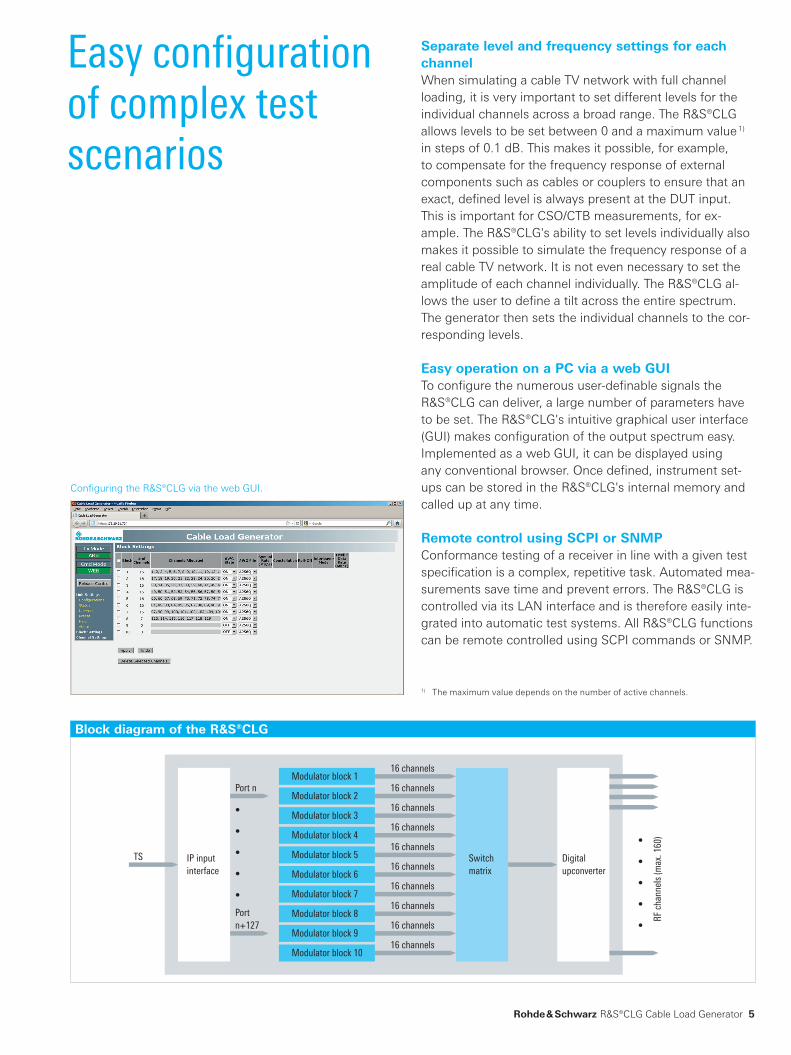
Configuring the R&S®CLG via the web GUI.
Block diagram of the ¸CLG
CLG_bro_en_5214-6416-12.indd 5 18.07.2014 15:15:18
¸SFU
Σ Receiver
DUT
••• ••• •••
¸CLG
6
The cable TV signals that arrive at viewers' living room outlets are far from ideal: Noise, reflections and adjacent-channel interferers degrade signal quality. Set-top boxes and other cable TV receivers must be able to handle such signals and supply viewers with high-quality images and sound. To ensure this, the American Society of Cable Tele-vision Engineers (SCTE) established the ANSI/SCTE 40 Digital Cable Network Interface Standard. The standard specifies that receivers must continue to function prop-erly when the following types of interference are present simultaneously: ❙ Broadband white noise ❙ Phase noise in the useful signal ❙ Micro-refl ections ❙ Superimposed amplitude modulation caused by AC hum ❙ Analog or digital adjacent-channel interferers ❙ Discrete CW interference signal in the useful channel ❙ Full channel loading of cable TV network
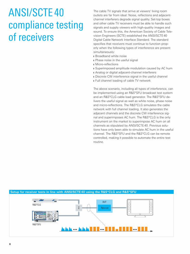
The above scenario, including all types of interference, can be implemented using an R&S®SFU broadcast test system and an R&S®CLG cable load generator. The R&S®SFU de-livers the useful signal as well as white noise, phase noise and micro-reflections. The R&S®CLG simulates the cable network with full channel loading. It also generates the adjacent channels and the discrete CW interference sig-nal and superimposes AC hum. The R&S®CLG is the only instrument on the market to superimpose AC hum on all channels as stipulated by ANSI/SCTE 40. Previous solu-tions have only been able to simulate AC hum in the useful channel. The R&S®SFU and the R&S®CLG can be remote controlled, making it possible to automate the entire test routine.
ANSI/SCTE 40 compliance testing of receivers
Setup for receiver tests in line with ANSI/SCTE 40 using the R&S®CLG and R&S®SFU
CLG_bro_en_5214-6416-12.indd 6 18.07.2014 15:15:18
Rohde & Schwarz R&S®CLG Cable Load Generator 7
Specifications in brief
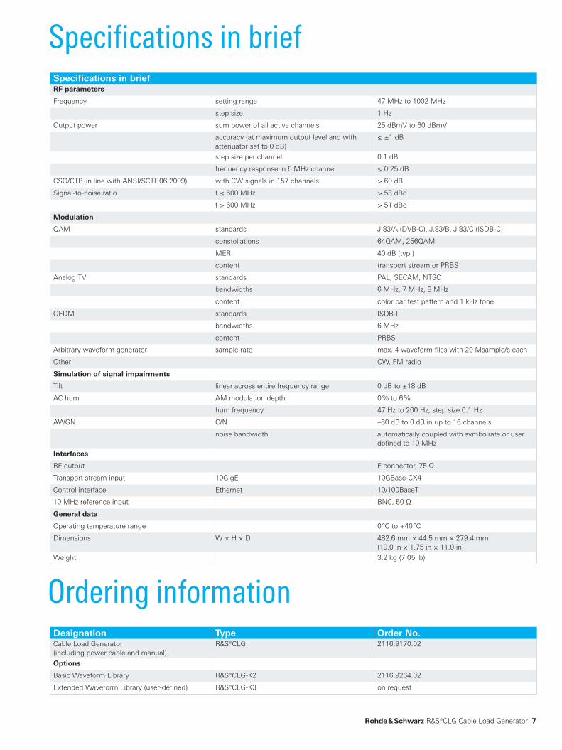
Ordering informationDesignation Type Order No.Cable Load Generator(including power cable and manual)
R&S®CLG 2116.9170.02
Options
Basic Waveform Library R&S®CLG-K2 2116.9264.02
Extended Waveform Library (user-defined) R&S®CLG-K3 on request
Specifications in briefRF parameters
Frequency setting range 47 MHz to 1002 MHz
step size 1 Hz
Output power sum power of all active channels 25 dBmV to 60 dBmV
accuracy (at maximum output level and with attenuator set to 0 dB)
≤ ±1 dB
step size per channel 0.1 dB
frequency response in 6 MHz channel ≤ 0.25 dB
CSO/CTB (in line with ANSI/SCTE 06 2009) with CW signals in 157 channels > 60 dB
Signal-to-noise ratio f ≤ 600 MHz > 53 dBc
f > 600 MHz > 51 dBc
Modulation
QAM standards J.83/A (DVB-C), J.83/B, J.83/C (ISDB-C)
constellations 64QAM, 256QAM
MER 40 dB (typ.)
content transport stream or PRBS
Analog TV standards PAL, SECAM, NTSC
bandwidths 6 MHz, 7 MHz, 8 MHz
content color bar test pattern and 1 kHz tone
OFDM standards ISDB-T
bandwidths 6 MHz
content PRBS
Arbitrary waveform generator sample rate max. 4 waveform files with 20 Msample/s each
Other CW, FM radio
Simulation of signal impairments
Tilt linear across entire frequency range 0 dB to ±18 dB
AC hum AM modulation depth 0 % to 6 %
hum frequency 47 Hz to 200 Hz, step size 0.1 Hz
AWGN C/N –60 dB to 0 dB in up to 16 channels
noise bandwidth automatically coupled with symbolrate or user defined to 10 MHz
Interfaces
RF output F connector, 75 Ω
Transport stream input 10GigE 10GBase-CX4
Control interface Ethernet 10/100BaseT
10 MHz reference input BNC, 50 Ω
General data
Operating temperature range 0 °C to +40 °C
Dimensions W × H × D 482.6 mm × 44.5 mm × 279.4 mm(19.0 in × 1.75 in × 11.0 in)
Weight 3.2 kg (7.05 lb)
CLG_bro_en_5214-6416-12.indd 7 18.07.2014 15:15:18
R&S® is a registered trademark of Rohde & Schwarz GmbH & Co. KG
Trade names are trademarks of the owners
PD 5214.6416.12 | Version 03.00 | July 2014 (as)
R&S®CLG Cable Load Generator
Data without tolerance limits is not binding | Subject to change
© 2011 - 2014 Rohde & Schwarz GmbH & Co. KG | 81671 Munich, Germany
Service that adds value❙ Worldwide ❙ Local and personalized❙ Customized and flexible❙ Uncompromising quality ❙ Long-term dependability
5214
.641
6.12
03.
00 P
DP
1 e
n
About Rohde & SchwarzThe Rohde & Schwarz electronics group is a leading supplier of solutions in the fields of test and measurement, broadcasting, secure communications, and radiomonitoring and radiolocation. Founded more than 80 years ago, this independent global company has an extensive sales network and is present in more than 70 countries. The company is headquartered in Munich, Germany.
Regional contact ❙ Europe, Africa, Middle East | +49 89 4129 12345 customersupport@rohdeschwarz.com
❙ North America | 1 888 TEST RSA (1 888 837 87 72) [email protected]schwarz.com
❙ Latin America | +1 410 910 79 88 customersupport.la@rohdeschwarz.com
❙ Asia/Pacific | +65 65 13 04 88 customersupport.asia@rohdeschwarz.com
❙ China | +86 800 810 8228/+86 400 650 5896 customersupport.china@rohdeschwarz.com
Rohde & Schwarz GmbH & Co. KGwww.rohdeschwarz.com
Sustainable product design ❙ Environmental compatibility and ecofootprint ❙ Energy efficiency and low emissions ❙ Longevity and optimized total cost of ownership
Certified Environmental Management
ISO 14001Certified Quality Management
ISO 9001
5214641612
CLG_bro_en_5214-6416-12.indd 8 18.07.2014 15:15:18