Embed Size (px)
Citation preview
As featured in:
See Nejc Hodnik, Miran Gaberšček, Karl J. J. Mayrhofer et al., Phys. Chem. Chem. Phys.,
2014, 16, 13610.
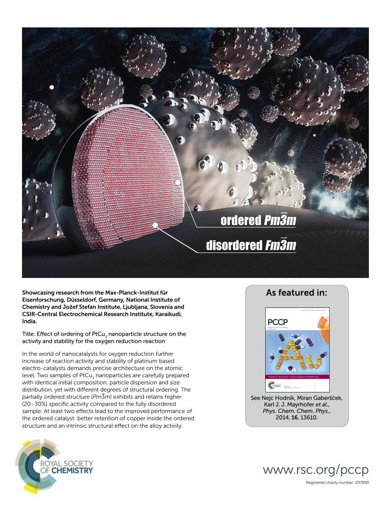
Showcasing research from the Max-Planck-Institut für
Eisenforschung, Düsseldorf, Germany, National Institute of
Chemistry and Jožef Stefan Institute, Ljubljana, Slovenia and
CSIR-Central Electrochemical Research Institute, Karaikudi,
India.
Title: Eff ect of ordering of PtCu3 nanoparticle structure on the
activity and stability for the oxygen reduction reaction
In the world of nanocatalysts for oxygen reduction further
increase of reaction activity and stability of platinum based
electro-catalysts demands precise architecture on the atomic
level. Two samples of PtCu3 nanoparticles are carefully prepared
with identical initial composition, particle dispersion and size
distribution, yet with diff erent degrees of structural ordering. The
partially ordered structure (Pm3m) exhibits and retains higher
(20–30%) specifi c activity compared to the fully disordered
sample. At least two eff ects lead to the improved performance of
the ordered catalyst: better retention of copper inside the ordered
structure and an intrinsic structural eff ect on the alloy activity.
Registered charity number: 207890
www.rsc.org/pccp
13610 | Phys. Chem. Chem. Phys., 2014, 16, 13610--13615 This journal is© the Owner Societies 2014
Cite this:Phys.Chem.Chem.Phys.,
2014, 16, 13610
Effect of ordering of PtCu3 nanoparticle structureon the activity and stability for the oxygenreduction reaction†
Nejc Hodnik,*ab Chinnaiah Jeyabharathi,ac Josef C. Meier,a Alexander Kostka,a
Kanala L. Phani,c Aleksander Recnik,d Marjan Bele,b Stanko Hocevar,b
Miran Gaberscek*a and Karl J. J. Mayrhofer*a
In this study the performance enhancement effect of structural ordering for the oxygen reduction reaction
(ORR) is systematically studied. Two samples of PtCu3 nanoparticles embedded on a graphitic carbon support
are carefully prepared with identical initial composition, particle dispersion and size distribution, yet with
different degrees of structural ordering. Thus we can eliminate all coinciding effects and unambiguously
relate the improved activity of the ORR and more importantly the enhanced stability to the ordered
nanostructure. Interestingly, the electrochemically induced morphological changes are common to both
ordered and disordered samples. The observed effect could have a groundbreaking impact on the future
directions in the rational design of active and stable platinum alloyed ORR catalysts.
Introduction
The oxygen reduction reaction (ORR) is the essential process inlow- to medium-temperature polymer electrolyte membrane fuelcells. In contrast to its anodic counterpart, i.e., the hydrogenoxidation reaction, the electrocatalysis of this cathodic reactionsuffers from large overpotentials and thus limits the overallperformance of the cell. Researchers across the globe are thereforeinvesting much effort to develop both active and durable industrialelectrocatalysts beyond the so far state-of-the-art Pt/C material,besides trying to reduce or even eliminate the noble metal con-tent.1,2 However, non-noble metal or metal-free catalysts still havelow mass activity and poor stability under the harsh operatingconditions in fuel cells. Pt based alloy electrodes have shown
promising mass activities 2–5 times higher than pure Pt, while atthe same time reducing the noble metal content.2 This enhance-ment is due to lower adsorption energies of blocking hydroxylspecies (OHad), yielding higher number of active sites available forthe ORR at comparable overpotentials.3–10 This holds even afterremoval of the transition metal from the catalyst surface andformation of a Pt rich shell, as the several times higher activity11
is retained due to the electronic (ligand effect) and geometric(strain effect) influence of the alloying element inside thecore.7,12,13 Upon selective leaching of the non-noble transitionmetal, either naturally under operating conditions or intentionallyas a pretreatment, several special structures have been obtained,such as, for instance, the Pt-skeleton shell/alloy-core,14 Pt-skinshell/alloy core,15 strained Pt shell/alloy-core,7 strained Pt shell/multi-core16 and ‘‘Swiss cheese’’ type porous particles.17 Thereby,the obtained structure depends on several parameters, such as thesynthesis conditions, the initial composition5,13 and the size ofthe alloyed material,8,13,18–20 as well as on the type of dealloyingprotocol used, e.g. chemical or electrochemical.6,9 An importantparameter that seems to have a significant impact on the finalproperties of electrochemically treated Pt-alloys is the effect ofstructural ordering, as shown for the ORR activity in PtCu,9,17,21
PtFe22,23 and PtCo24–26 systems. The stability of the so-calledintermetallic Pt-alloys, in contrast to disordered structures or solidsolutions, is however poorly understood. One reason is that theimpact of structural ordering is difficult to differentiate from othereffects, such as varying composition and particle size distribution31
resulting from different synthesis and pretreatment conditions,especially during annealing.24–26 In this study we eliminate all
a Max-Planck-Institut fur Eisenforschung GmbH, Max-Planck Str. 1,
40237 Dusseldorf, Germany. E-mail: [email protected], [email protected];
Fax: +49 211 6792 218; Tel: +49 211 6792 160b National Institute of Chemistry, Hajdrihova 19, 1000 Ljubljana, Slovenia.
E-mail: [email protected]; Fax: +386 1 4760 300; Tel: +386 1 4760 320c CSIR-Central Electrochemical Research Institute, Karaikudi 630 006, Tamil Nadu,
Indiad Department for Nanostructured Materials, Jozef Stefan Institute, Ljubljana, 1000,
Slovenia
† Electronic supplementary information (ESI) available: Description of structural,electrochemical, ICP-MS and IL-TEM characterization methods and experimentalconditions. Dealloying cyclovoltammograms (500 cycles), ORR polarisation curvesand SEM pictures of ordered and disordered catalysts. IL-TEM, IL-tomographymovie and TEM images of ordered catalysts. 3 tables with ORR activities (massand specific) and ECSA measured after all electrochemical treatments togetherwith copper content data. See DOI: 10.1039/c4cp00585f
Received 8th February 2014,Accepted 10th April 2014
DOI: 10.1039/c4cp00585f
www.rsc.org/pccp
PCCP
PAPER
Ope
n A
cces
s A
rtic
le. P
ublis
hed
on 1
0 A
pril
2014
. Dow
nloa
ded
on 3
/13/
2022
1:0
9:02
AM
. T
his
artic
le is
lice
nsed
und
er a
Cre
ativ
e C
omm
ons
Attr
ibut
ion-
Non
Com
mer
cial
3.0
Unp
orte
d L
icen
ce.
View Article OnlineView Journal | View Issue
This journal is© the Owner Societies 2014 Phys. Chem. Chem. Phys., 2014, 16, 13610--13615 | 13611
these coinciding effects and unambiguously demonstrate animproved activity and even more importantly an enhanced stabilityof a partially ordered catalyst, exemplified by PtCu3.
Experimental
PtCu3 alloy nanoparticles supported on a commercially availablegraphite support (Vulcan XC72R) were synthesized by a modifiedsol–gel method, and alloying of Pt with Cu was achieved by thermalannealing (above 700 1C) as described in the patent literature.19,27
The catalyst composite contains 23.8 wt% Cu and 25.5 wt% Pt. Thepartially ordered analogue consisting of a combination of ordered(Pm%3m) and disordered (Fm%3m) structures was obtained by settingthe temperature below the order–disorder transition temperature(B550 1C) so that the system attained thermodynamic equilibrium.By contrast, a completely disordered PtCu3 analogue (s.s.; Fm%3mstructure) was obtained from the partially ordered material byheating to 700 1C, above the disorder–order transition temperature,and quenching in liquid nitrogen.
Results and discussion
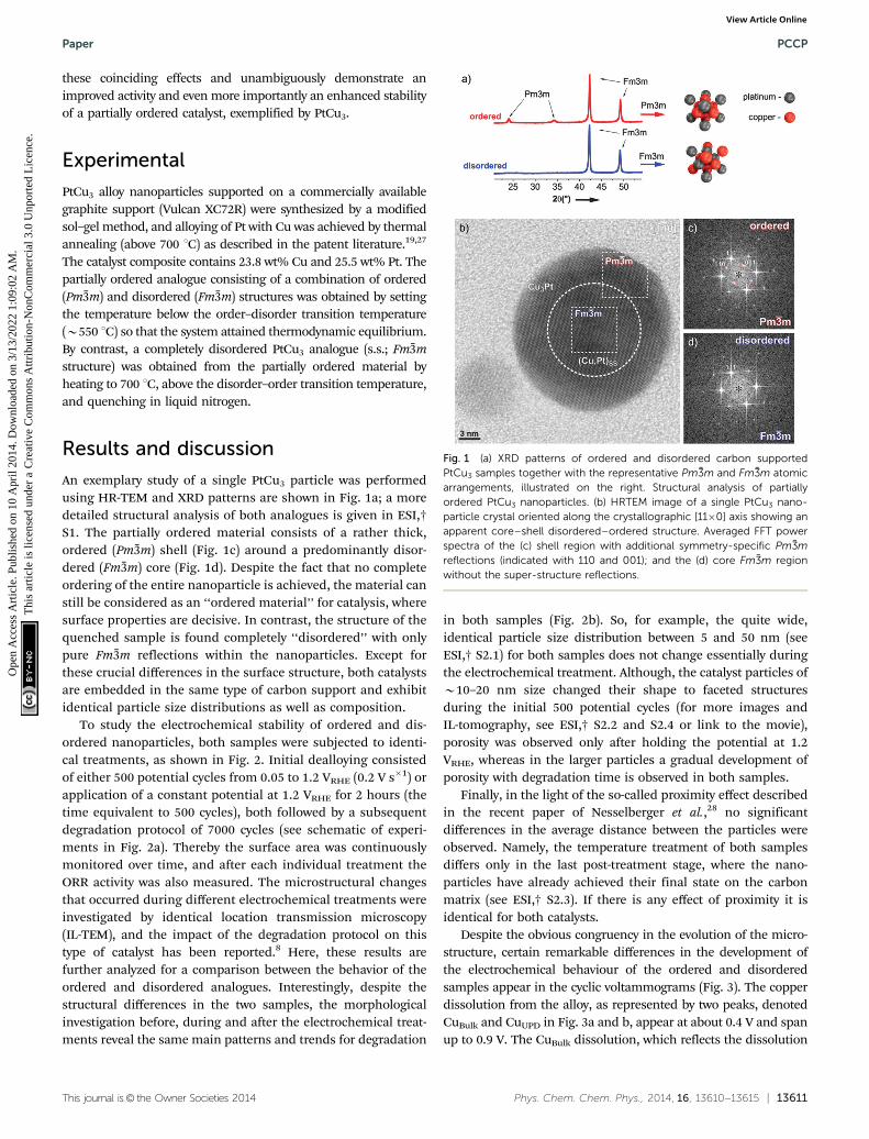
An exemplary study of a single PtCu3 particle was performedusing HR-TEM and XRD patterns are shown in Fig. 1a; a moredetailed structural analysis of both analogues is given in ESI,†S1. The partially ordered material consists of a rather thick,ordered (Pm%3m) shell (Fig. 1c) around a predominantly disor-dered (Fm%3m) core (Fig. 1d). Despite the fact that no completeordering of the entire nanoparticle is achieved, the material canstill be considered as an ‘‘ordered material’’ for catalysis, wheresurface properties are decisive. In contrast, the structure of thequenched sample is found completely ‘‘disordered’’ with onlypure Fm%3m reflections within the nanoparticles. Except forthese crucial differences in the surface structure, both catalystsare embedded in the same type of carbon support and exhibitidentical particle size distributions as well as composition.
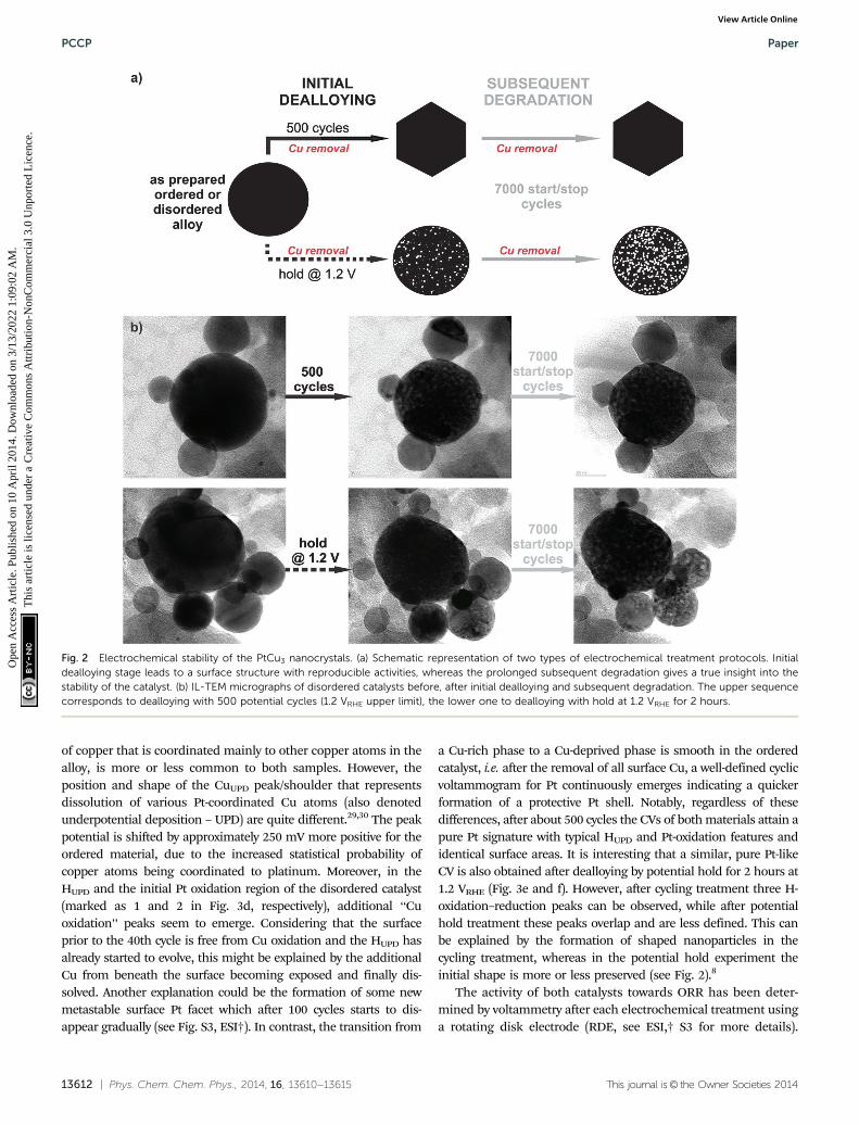
To study the electrochemical stability of ordered and dis-ordered nanoparticles, both samples were subjected to identi-cal treatments, as shown in Fig. 2. Initial dealloying consistedof either 500 potential cycles from 0.05 to 1.2 VRHE (0.2 V s�1) orapplication of a constant potential at 1.2 VRHE for 2 hours (thetime equivalent to 500 cycles), both followed by a subsequentdegradation protocol of 7000 cycles (see schematic of experi-ments in Fig. 2a). Thereby the surface area was continuouslymonitored over time, and after each individual treatment theORR activity was also measured. The microstructural changesthat occurred during different electrochemical treatments wereinvestigated by identical location transmission microscopy(IL-TEM), and the impact of the degradation protocol on thistype of catalyst has been reported.8 Here, these results arefurther analyzed for a comparison between the behavior of theordered and disordered analogues. Interestingly, despite thestructural differences in the two samples, the morphologicalinvestigation before, during and after the electrochemical treat-ments reveal the same main patterns and trends for degradation
in both samples (Fig. 2b). So, for example, the quite wide,identical particle size distribution between 5 and 50 nm (seeESI,† S2.1) for both samples does not change essentially duringthe electrochemical treatment. Although, the catalyst particles ofB10–20 nm size changed their shape to faceted structuresduring the initial 500 potential cycles (for more images andIL-tomography, see ESI,† S2.2 and S2.4 or link to the movie),porosity was observed only after holding the potential at 1.2VRHE, whereas in the larger particles a gradual development ofporosity with degradation time is observed in both samples.
Finally, in the light of the so-called proximity effect describedin the recent paper of Nesselberger et al.,28 no significantdifferences in the average distance between the particles wereobserved. Namely, the temperature treatment of both samplesdiffers only in the last post-treatment stage, where the nano-particles have already achieved their final state on the carbonmatrix (see ESI,† S2.3). If there is any effect of proximity it isidentical for both catalysts.
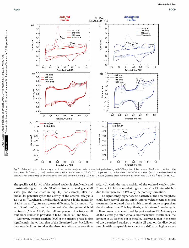
Despite the obvious congruency in the evolution of the micro-structure, certain remarkable differences in the development ofthe electrochemical behaviour of the ordered and disorderedsamples appear in the cyclic voltammograms (Fig. 3). The copperdissolution from the alloy, as represented by two peaks, denotedCuBulk and CuUPD in Fig. 3a and b, appear at about 0.4 V and spanup to 0.9 V. The CuBulk dissolution, which reflects the dissolution
Fig. 1 (a) XRD patterns of ordered and disordered carbon supportedPtCu3 samples together with the representative Pm %3m and Fm %3m atomicarrangements, illustrated on the right. Structural analysis of partiallyordered PtCu3 nanoparticles. (b) HRTEM image of a single PtCu3 nano-particle crystal oriented along the crystallographic [11�0] axis showing anapparent core–shell disordered–ordered structure. Averaged FFT powerspectra of the (c) shell region with additional symmetry-specific Pm %3mreflections (indicated with 110 and 001); and the (d) core Fm %3m regionwithout the super-structure reflections.
Paper PCCP
Ope
n A
cces
s A
rtic
le. P
ublis
hed
on 1
0 A
pril
2014
. Dow
nloa
ded
on 3
/13/
2022
1:0
9:02
AM
. T
his
artic
le is
lice
nsed
und
er a
Cre
ativ
e C
omm
ons
Attr
ibut
ion-
Non
Com
mer
cial
3.0
Unp
orte
d L
icen
ce.
View Article Online
13612 | Phys. Chem. Chem. Phys., 2014, 16, 13610--13615 This journal is© the Owner Societies 2014
of copper that is coordinated mainly to other copper atoms in thealloy, is more or less common to both samples. However, theposition and shape of the CuUPD peak/shoulder that representsdissolution of various Pt-coordinated Cu atoms (also denotedunderpotential deposition – UPD) are quite different.29,30 The peakpotential is shifted by approximately 250 mV more positive for theordered material, due to the increased statistical probability ofcopper atoms being coordinated to platinum. Moreover, in theHUPD and the initial Pt oxidation region of the disordered catalyst(marked as 1 and 2 in Fig. 3d, respectively), additional ‘‘Cuoxidation’’ peaks seem to emerge. Considering that the surfaceprior to the 40th cycle is free from Cu oxidation and the HUPD hasalready started to evolve, this might be explained by the additionalCu from beneath the surface becoming exposed and finally dis-solved. Another explanation could be the formation of some newmetastable surface Pt facet which after 100 cycles starts to dis-appear gradually (see Fig. S3, ESI†). In contrast, the transition from
a Cu-rich phase to a Cu-deprived phase is smooth in the orderedcatalyst, i.e. after the removal of all surface Cu, a well-defined cyclicvoltammogram for Pt continuously emerges indicating a quickerformation of a protective Pt shell. Notably, regardless of thesedifferences, after about 500 cycles the CVs of both materials attain apure Pt signature with typical HUPD and Pt-oxidation features andidentical surface areas. It is interesting that a similar, pure Pt-likeCV is also obtained after dealloying by potential hold for 2 hours at1.2 VRHE (Fig. 3e and f). However, after cycling treatment three H-oxidation–reduction peaks can be observed, while after potentialhold treatment these peaks overlap and are less defined. This canbe explained by the formation of shaped nanoparticles in thecycling treatment, whereas in the potential hold experiment theinitial shape is more or less preserved (see Fig. 2).8
The activity of both catalysts towards ORR has been deter-mined by voltammetry after each electrochemical treatment usinga rotating disk electrode (RDE, see ESI,† S3 for more details).
Fig. 2 Electrochemical stability of the PtCu3 nanocrystals. (a) Schematic representation of two types of electrochemical treatment protocols. Initialdealloying stage leads to a surface structure with reproducible activities, whereas the prolonged subsequent degradation gives a true insight into thestability of the catalyst. (b) IL-TEM micrographs of disordered catalysts before, after initial dealloying and subsequent degradation. The upper sequencecorresponds to dealloying with 500 potential cycles (1.2 VRHE upper limit), the lower one to dealloying with hold at 1.2 VRHE for 2 hours.
PCCP Paper
Ope
n A
cces
s A
rtic
le. P
ublis
hed
on 1
0 A
pril
2014
. Dow
nloa
ded
on 3
/13/
2022
1:0
9:02
AM
. T
his
artic
le is
lice
nsed
und
er a
Cre
ativ
e C
omm
ons
Attr
ibut
ion-
Non
Com
mer
cial
3.0
Unp
orte
d L
icen
ce.
View Article Online
This journal is© the Owner Societies 2014 Phys. Chem. Chem. Phys., 2014, 16, 13610--13615 | 13613
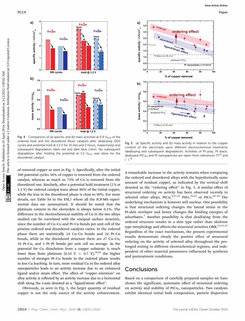
The specific activity (SA) of the ordered catalyst is significantly andconsistently higher than the SA of its disordered analogue at allstates (see the bar chart in Fig. 4a). For example, after theinitial 500 potential cycles the activity of the ordered catalyst is2.5 mA cm�2
Pt, whereas the disordered catalyst exhibits an activityof 1.78 mA cm�2
Pt. An even greater difference, i.e. 2.4 mA cm�2Pt
vs. 1.5 mA cm�2Pt, can be observed after the potential hold
treatment (2 h at 1.2 V), the full comparison of activity at allconditions studied is provided in ESI,† Tables S3.1 and S3.2.
Moreover, the mass activity (MA) of the ordered phase is alsosignificantly higher than that of the disordered one, but followsthe same declining trend as the absolute surface area over time
(Fig. 4b). Only the mass activity of the ordered catalyst after2 hours of hold is somewhat higher than after 15 min, which isdue to the increase in ECSA by the porosity formation.
The significantly higher specific activity of the ordered phasecould have several origins. Firstly, after a typical electrochemicaltreatment the ordered phase is able to retain more copper thanthe disordered one. This hypothesis, which stems from the cyclicvoltammograms, is confirmed by post-mortem ICP-MS analysisof the electrolyte after various electrochemical treatments: theamount of Cu leached out of the alloy is always higher in the caseof the disordered catalyst. Therefore all data on the disorderedsample with comparable treatment are shifted to higher values
Fig. 3 Selected cyclic voltammograms of the continuously recorded scans during dealloying with 500 cycles of the ordered Pm %3m (a, c; red) and thedisordered Fm %3m (b, d; blue) catalyst, recorded at a scan rate of 0.2 V s�1. Comparison of the baseline scans of the ordered (e) and the disordered (f)catalyst after dealloying by cycling (solid line) and potential hold @ 1.2 V for 2 hours (dashed line), recorded at a scan rate 0.05 V s�1 in 0.1 M HClO4.
Paper PCCP
Ope
n A
cces
s A
rtic
le. P
ublis
hed
on 1
0 A
pril
2014
. Dow
nloa
ded
on 3
/13/
2022
1:0
9:02
AM
. T
his
artic
le is
lice
nsed
und
er a
Cre
ativ
e C
omm
ons
Attr
ibut
ion-
Non
Com
mer
cial
3.0
Unp
orte
d L
icen
ce.
View Article Online
13614 | Phys. Chem. Chem. Phys., 2014, 16, 13610--13615 This journal is© the Owner Societies 2014
of removed copper as seen in Fig. 5. Specifically, after the initial500 potential cycles 56% of copper is removed from the orderedcatalyst, whereas as much as 73% of Cu is removed from thedisordered one. Similarly, after a potential hold treatment (2 h at1.2 V) the ordered catalyst loses about 80% of the initial copper,while the loss in the disordered phase is close to 90%. For moredetails, see Table S4 in the ESI,† where all the ICP-MS experi-mental data are summarized. It should be noted that theplatinum content in the electrolyte is always below 0.1%. Thedifference in the electrochemical stability of Cu in the two alloysstudied can be correlated with the unequal surface structure,since the number of Cu–Cu and Pt–Cu bonds per unit cell of thepristine ordered and disordered catalysts varies. In the orderedphase there are statistically 24 Cu–Cu bonds and 24 Pt–Cubonds, while in the disordered structure there are 27 Cu–Cu,18 Pt–Cu, and 3 Pt–Pt bonds per unit cell on average. As thepotential for Cu dissolution from a copper substrate is muchlower than from platinum (0.34 V o 0.7 V),18,29 the highernumber of stronger Pt–Cu bonds in the ordered phase resultsin less Cu leaching. In turn, more residual Cu in the ordered alloynanoparticles leads to an activity increase due to an enhancedligand and/or strain effect. The effect of ‘‘copper retention’’ onalloy activity is reflected by an activity increase due to a horizontalshift along the x-axis denoted as a ‘‘ligand/strain effect’’.
Obviously, as seen in Fig. 5, the larger quantity of residualcopper is not the only source of the activity enhancement.
A remarkable increase in the activity remains when comparingthe ordered and disordered alloys with the hypothetically sameamount of residual copper, as indicated by the vertical shiftdenoted as the ‘‘ordering effect’’ in Fig. 5. A similar effect ofstructural ordering on activity has been observed recently inselected other alloys, PtCu,9,17,21 PtFe,22,23 or PtCo.24–26 Theunderlying mechanism is however still unclear. One possibilityis that structural ordering changes the lateral strain in thePt-skin overlayer and hence changes the binding energies ofadsorbates.7 Another possibility is that dealloying from theordered structure results in a skin type rather than skeletontype morphology and affects the structural sensitive ORR.14,15,31
Regardless of the exact mechanism, the present experimentalresults demonstrate clearly the positive effect of structuralordering on the activity of selected alloy throughout the pro-longed testing in different electrochemical regimes, and inde-pendent of other material parameters influenced by synthesisand pretreatment conditions.
Conclusions
Based on a comparison of carefully prepared samples we haveshown the significant, systematic effect of structural orderingon activity and stability of PtCu3 nanoparticles. Two catalystsexhibit identical initial bulk composition, particle dispersion
Fig. 4 Comparison of (a) specific and (b) mass activities @ 0.9 VRHE of theordered (red) and the disordered (blue) catalysts after dealloying (500cycles and potential hold @ 1.2 V for 15 min and 2 hours, respectively) andsubsequent degradation (dark red and dark blue color). No subsequentdegradation after holding the potential at 1.2 VRHE was done for thedisordered catalyst.
Fig. 5 (a) Specific activity and (b) mass activity in relation to the coppercontent of the electrolyte upon different electrochemical treatments(dealloying and subsequent degradation). Activities of Pt-poly, Pt-black,dealloyed PtCu3 and Pt nanoparticles are taken from references (*)32 and(�).18
PCCP Paper
Ope
n A
cces
s A
rtic
le. P
ublis
hed
on 1
0 A
pril
2014
. Dow
nloa
ded
on 3
/13/
2022
1:0
9:02
AM
. T
his
artic
le is
lice
nsed
und
er a
Cre
ativ
e C
omm
ons
Attr
ibut
ion-
Non
Com
mer
cial
3.0
Unp
orte
d L
icen
ce.
View Article Online
This journal is© the Owner Societies 2014 Phys. Chem. Chem. Phys., 2014, 16, 13610--13615 | 13615
and size distribution, with the only difference being the degreeof structural order induced by different thermal annealing.As expected, the activity of both alloys decreases with the increasein time of exposure to harsh electrochemical treatment conditions.However, regardless of the degradation/dealloying treatment, thepartially ordered structure (Pm%3m) contains significantly higher(20–30%) specific activity compared to the fully disordered sample.At least two effects lead to the improved performance of theordered catalyst: (1) a better retention of copper inside the orderedstructure after a given treatment and (2) an intrinsic structuraleffect on the alloy activity. The latter could be due to modifiedlateral strain in the Pt skin7 overlayer and/or due to the differentmorphology of the de-alloyed material.14
Acknowledgements
The work was financed in part by the Slovenian Centre of ExcellenceLow Carbon Technologies (CO NOT). We would also like to thankAndrea Mingers, Milena Zorko and Barbara Jozinovic for theirassistance and the professional graphic designer Jaka Birsa for hishelp with TOC. C.J. thanks the DAAD (Germany) for a SandwichModel Fellowship and CSIR (India) for support.
Notes and references
1 A. Rabis, P. Rodriguez and T. J. Schmidt, ACS Catal., 2012, 2,864–890.
2 M. K. Debe, Nature, 2012, 486, 43–51.3 S. Mukerjee, S. Srinivasan, M. P. Soriaga and J. McBreen,
J. Electrochem. Soc., 1995, 142, 1409–1422.4 V. R. Stamenkovic, B. Fowler, B. S. Mun, G. Wang, P. N. Ross,
C. A. Lucas and N. M. Markovic, Science, 2007, 315, 493–497.5 L. Gan, M. Heggen, S. Rudi and P. Strasser, Nano Lett., 2012,
12, 5423–5430.6 L. Gan, M. Heggen, R. O’Malley, B. Theobald and P. Strasser,
Nano Lett., 2013, 13, 1131–1138.7 P. Strasser, S. Koh, T. Anniyev, J. Greeley, K. More, C. Yu,
Z. Liu, S. Kaya, D. Nordlund, H. Ogasawara, M. F. Toney andA. Nilsson, Nat. Chem., 2010, 2, 454–460.
8 C. Jeyabharathi, N. Hodnik, C. Baldizzone, J. C. Meier,M. Heggen, K. L. N. Phani, M. Bele, M. Zorko, S. Hocevarand K. J. J. Mayrhofer, ChemCatChem, 2013, 5, 2627–2635.
9 D. Wang, Y. Yu, H. L. Xin, R. Hovden, P. Ercius, J. A. Mundy,H. Chen, J. H. Richard, D. A. Muller, F. J. DiSalvo andH. D. Abruna, Nano Lett., 2012, 12, 5230–5238.
10 N. Hodnik, M. Bele and S. Hocevar, Electrochem. Commun.,2012, 23, 125–128.
11 R. Srivastava, P. Mani, N. Hahn and P. Strasser, Angew.Chem., Int. Ed., 2007, 46, 8988–8991.
12 J. Greeley, I. E. Stephens, A. S. Bondarenko, T. P. Johansson,H. A. Hansen, T. F. Jaramillo, J. Rossmeisl, I. Chorkendorffand J. K. Nørskov, Nat. Chem., 2009, 1, 552–556.
13 J. Snyder, I. McCue, K. Livi and J. Erlebacher, J. Am. Chem.Soc., 2012, 134, 8633–8645.
14 V. R. Stamenkovic, B. S. Mun, M. Arenz, K. J. J. Mayrhofer,C. A. Lucas, G. Wang, P. N. Ross and N. M. Markovic, Nat.Mater., 2007, 6, 241–247.
15 C. Wang, M. Chi, D. Li, D. Strmcnik, D. van der Vliet,G. Wang, V. Komanicky, K. C. Chang, A. P. Paulikas,D. Tripkovic, J. Pearson, K. L. More, N. M. Markovic andV. R. Stamenkovic, J. Am. Chem. Soc., 2011, 133,14396–14403.
16 M. Heggen, M. Oezaslan, L. Houben and P. Strasser, J. Phys.Chem. C, 2012, 116, 19073–19083.
17 I. Dutta, M. K. Carpenter, M. P. Balogh, J. M. Ziegelbauer,T. E. Moylan, M. H. Atwan and N. P. Irish, J. Phys. Chem. C,2010, 114, 16309–16320.
18 M. Oezaslan, M. Heggen and P. Strasser, J. Am. Chem. Soc.,2011, 134, 514–524.
19 N. Hodnik, M. Zorko, M. Bele, S. Hocevar and M. Gaberscek,J. Phys. Chem. C, 2012, 116, 21326–21333.
20 I. McCue, J. Snyder, X. Li, Q. Chen, K. Sieradzki andJ. Erlebacher, Phys. Rev. Lett., 2012, 108, 225503.
21 N. Hodnik, M. Bele, A. Recnik, N. Z. Logar, M. Gaberscekand S. Hocevar, Energy Procedia, 2012, 29, 208–215.
22 H. Chen, D. Wang, Y. Yu, K. A. Newton, D. A. Muller,H. Abruna and F. J. DiSalvo, J. Am. Chem. Soc., 2012, 134,18453–18459.
23 J. Kim, Y. Lee and S. Sun, J. Am. Chem. Soc., 2010, 132,4996–4997.
24 D. Wang, H. L. Xin, R. Hovden, H. Wang, Y. Yu, D. A. Muller,F. J. DiSalvo and H. D. Abruna, Nat. Mater., 2013, 12, 81–87.
25 M. Watanabe, K. Tsurumi, T. Mizukami, T. Nakamura andP. Stonehart, J. Electrochem. Soc., 1994, 141, 2659–2668.
26 S. Koh, M. F. Toney and P. Strasser, Electrochim. Acta, 2007,52, 2765–2774.
27 M. Bele, M. Gaberscek, G. Kapun, N. Hodnik and S. Hocevar,Electrocatalytic Composite(s), Associated Composition(s) andAssociated Process(es): Patentna Prijava: US Appln, UnitedStates Patent and Trademark Office, 2011.
28 M. Nesselberger, M. Roefzaad, R. Fayçal Hamou, P. UlrichBiedermann, F. F. Schweinberger, S. Kunz, K. Schloegl,G. K. H. Wiberg, S. Ashton, U. Heiz, K. J. J. Mayrhofer andM. Arenz, Nat. Mater., 2013, 12, 919–924.
29 P. Strasser, S. Koh and J. Greeley, Phys. Chem. Chem. Phys.,2008, 10, 3670–3683.
30 D. M. Kolb, M. Przasnyski and H. Gerischer, J. Electroanal.Chem. Interfacial Electrochem., 1974, 54, 25–38.
31 D. F. van der Vliet, C. Wang, D. Tripkovic, D. Strmcnik,X. F. Zhang, M. K. Debe, R. T. Atanasoski, N. M. Markovicand V. R. Stamenkovic, Nat. Mater., 2012, 11, 1051–1058.
32 M. Nesselberger, S. Ashton, J. C. Meier, I. Katsounaros,K. J. J. Mayrhofer and M. Arenz, J. Am. Chem. Soc., 2011,133, 17428–17433.
Paper PCCP
Ope
n A
cces
s A
rtic
le. P
ublis
hed
on 1
0 A
pril
2014
. Dow
nloa
ded
on 3
/13/
2022
1:0
9:02
AM
. T
his
artic
le is
lice
nsed
und
er a
Cre
ativ
e C
omm
ons
Attr
ibut
ion-
Non
Com
mer
cial
3.0
Unp
orte
d L
icen
ce.
View Article Online