Embed Size (px)
Citation preview
R&S®SMW-K49IEEE 802.16 WiMAXTM
User Manual
User
Man
ual
Versi
on 12
1175673202(;ÙÑP2)
This document describes the following software options:
● R&S®SMW-K491413.3984.xx
This manual describes firmware version FW 4.30.005.xx and later of the R&S®SMW200A.
© 2018 Rohde & Schwarz GmbH & Co. KGMühldorfstr. 15, 81671 München, GermanyPhone: +49 89 41 29 - 0Fax: +49 89 41 29 12 164Email: [email protected]: www.rohde-schwarz.comSubject to change – Data without tolerance limits is not binding.R&S® is a registered trademark of Rohde & Schwarz GmbH & Co. KG.WiMAX Forum® is a registered trademark of the WiMAX Forum. WiMAXTM, the WiMAX Forum logo, WiMAX Forum CertifiedTM andthe WiMAX Forum Certified logo are trademarks of the WiMAX Forum.Trade names are trademarks of the owners.
1175.6732.02 | Version 12 | R&S®SMW-K49
The following abbreviations are used throughout this manual: R&S®SMW200A is abbreviated as R&S SMW, R&S®WinIQSIM2TM isabbreviated as R&S WinIQSIM2; the license types 02/03/07/11/13/16/12 are abbreviated as xx.
ContentsR&S®SMW-K49
3User Manual 1175.6732.02 ─ 12
Contents1 Preface.................................................................................................... 7
1.1 Documentation Overview............................................................................................. 7
1.1.1 Getting Started Manual................................................................................................... 7
1.1.2 User Manuals and Help...................................................................................................7
1.1.3 Tutorials...........................................................................................................................7
1.1.4 Service Manual............................................................................................................... 8
1.1.5 Instrument Security Procedures......................................................................................8
1.1.6 Basic Safety Instructions.................................................................................................8
1.1.7 Data Sheets and Brochures............................................................................................ 8
1.1.8 Release Notes and Open Source Acknowledgment (OSA)............................................ 8
1.1.9 Application Notes, Application Cards, White Papers, etc................................................8
2 Welcome to the IEEE 802.16 WiMAX Digital Standard....................... 92.1 Accessing the IEEE 802.16 WiMAX Dialog................................................................. 9
2.2 Scope........................................................................................................................... 10
2.3 Notes on Screenshots................................................................................................ 10
3 About the IEEE 802.16 WiMAX Option............................................... 11
4 WiMAX Configuration and Settings....................................................144.1 General Settings for WiMAX Signals.........................................................................14
4.2 Trigger Settings...........................................................................................................19
4.3 Marker Settings........................................................................................................... 24
4.4 Clock Settings............................................................................................................. 26
4.5 Local and Global Connector Settings....................................................................... 28
4.6 Frame Configuration General Settings..................................................................... 28
4.7 Frame Configuration OFDM....................................................................................... 30
4.7.1 Frame Configuration Common Settings........................................................................31
4.7.2 Burst Table.................................................................................................................... 34
4.7.3 Frame Burst Graph OFDM............................................................................................38
4.7.4 Active Carrier Graph OFDM..........................................................................................40
4.8 FCH Configuration Downlink OFDM..........................................................................41
4.9 Generate UL-MAP Uplink OFDM................................................................................ 43
ContentsR&S®SMW-K49
4User Manual 1175.6732.02 ─ 12
4.10 DL-MAP Configuration Downlink OFDM................................................................... 45
4.11 UL-MAP Configuration Downlink OFDM................................................................... 47
4.12 More Parameters Uplink OFDM................................................................................. 48
4.13 MAC Header Configuration OFDM.............................................................................49
4.14 Frame Configuration OFDMA.....................................................................................51
4.14.1 Frame Configuration Common Settings........................................................................52
4.14.2 Zone Table.................................................................................................................... 55
4.14.3 Time Plan...................................................................................................................... 57
4.15 Zone Configuration OFDMA.......................................................................................58
4.15.1 OFDMA Common Zone Settings.................................................................................. 58
4.15.2 Burst Table.................................................................................................................... 63
4.15.3 Time Plan OFDMA........................................................................................................ 68
4.16 Sounding Zone Configuration OFDMA..................................................................... 69
4.16.1 OFDMA Sounding Zone Settings..................................................................................69
4.16.2 Sounding Table............................................................................................................. 73
4.17 CSTD OFDMA.............................................................................................................. 76
4.18 Data Configuration OFDMA........................................................................................78
4.18.1 OFDMA Data Configuration Settings............................................................................ 79
4.18.2 PDU Table..................................................................................................................... 83
4.19 FCH Configuration Downlink OFDMA....................................................................... 86
4.20 DL-MAP Configuration Downlink OFDMA.................................................................88
4.21 UL-MAP Configuration Downlink OFDMA.................................................................94
4.22 Generate UL-MAP Uplink OFDMA............................................................................. 99
4.23 Ranging Uplink OFDMA............................................................................................100
4.24 HARQ Configuration OFDMA...................................................................................102
4.24.1 OFDMA HARQ Settings..............................................................................................103
4.24.2 HARQ Sub-Burst Table............................................................................................... 105
4.25 Fast Feedback Configuration OFDMA.................................................................... 109
4.26 SUB-DL-UL-MAP Configuration OFDMA................................................................. 111
4.27 MAC Header Configuration OFDMA........................................................................ 113
4.28 PDU MAC Configuration OFDMA.............................................................................115
4.29 Filter / Clipping Settings........................................................................................... 118
4.29.1 Filter Settings...............................................................................................................118
ContentsR&S®SMW-K49
5User Manual 1175.6732.02 ─ 12
4.29.2 Clipping Settings......................................................................................................... 121
4.29.3 Data Dump.................................................................................................................. 122
5 Remote-Control Commands............................................................. 1245.1 General Commands.................................................................................................. 125
5.2 Filter/Clipping Settings.............................................................................................131
5.3 Trigger Settings.........................................................................................................136
5.4 Marker Settings......................................................................................................... 141
5.5 Clock Settings........................................................................................................... 143
5.6 OFDMA Physical Layer Settings..............................................................................144
5.7 OFDM Physical Layer Settings................................................................................ 207
List of Commands..............................................................................226
Index....................................................................................................232
ContentsR&S®SMW-K49
6User Manual 1175.6732.02 ─ 12
PrefaceR&S®SMW-K49
7User Manual 1175.6732.02 ─ 12
1 Preface
1.1 Documentation Overview
This section provides an overview of the R&S SMW user documentation. Unless speci-fied otherwise, you find the documents on the R&S SMW product page at:
www.rohde-schwarz.com/manual/smw200a
1.1.1 Getting Started Manual
Introduces the R&S SMW and describes how to set up and start working with the prod-uct. Includes basic operations, typical measurement examples, and general informa-tion, e.g. safety instructions, etc. A printed version is delivered with the instrument.
1.1.2 User Manuals and Help
Separate manuals for the base unit and the software options are provided for down-load:● Base unit manual
Contains the description of all instrument modes and functions. It also provides anintroduction to remote control, a complete description of the remote control com-mands with programming examples, and information on maintenance, instrumentinterfaces and error messages. Includes the contents of the getting started manual.
● Software option manualContains the description of the specific functions of an option. Basic information onoperating the R&S SMW is not included.
The contents of the user manuals are available as help in the R&S SMW. The helpoffers quick, context-sensitive access to the complete information for the base unit andthe software options.
All user manuals are also available for download or for immediate display on the Inter-net.
1.1.3 Tutorials
The R&S SMW provides interactive examples and demonstrations on operating theinstrument in form of tutorials. A set of tutorials is available directly on the instrument.
Documentation Overview
PrefaceR&S®SMW-K49
8User Manual 1175.6732.02 ─ 12
1.1.4 Service Manual
Describes the performance test for checking the rated specifications, module replace-ment and repair, firmware update, troubleshooting and fault elimination, and containsmechanical drawings and spare part lists.
The service manual is available for registered users on the global Rohde & Schwarzinformation system (GLORIS, https://gloris.rohde-schwarz.com).
1.1.5 Instrument Security Procedures
Deals with security issues when working with the R&S SMW in secure areas. It is avail-able for download on the Internet.
1.1.6 Basic Safety Instructions
Contains safety instructions, operating conditions and further important information.The printed document is delivered with the instrument.
1.1.7 Data Sheets and Brochures
The data sheet contains the technical specifications of the R&S SMW. It also lists theoptions and their order numbers and optional accessories.
The brochure provides an overview of the instrument and deals with the specific char-acteristics.
See www.rohde-schwarz.com/brochure-datasheet/smw200a
1.1.8 Release Notes and Open Source Acknowledgment (OSA)
The release notes list new features, improvements and known issues of the currentfirmware version, and describe the firmware installation.
The open source acknowledgment document provides verbatim license texts of theused open source software.
See www.rohde-schwarz.com/firmware/smw200a
1.1.9 Application Notes, Application Cards, White Papers, etc.
These documents deal with special applications or background information on particu-lar topics.
See www.rohde-schwarz.com/application/smw200a.
Documentation Overview
Welcome to the IEEE 802.16 WiMAX Digital StandardR&S®SMW-K49
9User Manual 1175.6732.02 ─ 12
2 Welcome to the IEEE 802.16 WiMAX DigitalStandardThe R&S SMW-K49 is a firmware application that adds functionality to generate sig-nals in accordance with the IEEE 802.16 standard WiMAX.
The R&S SMW-K49 key features
The R&S SMW simulates IEEE 802.16 WiMAX at the physical level. The IEEE 802.16WiMAX signals are generated in the arbitrary waveform mode; the signal is first calcu-lated and then output. The following list gives an overview of the main functions:● Support of IEEE 802.16TM-2004/Cor1/D5 and IEEE 802.16e-2005● Physical layer modes: OFDM, OFDMA, OFDMA/WiBro● Forward and reverse link, FDD and TDD duplexing● Burst types: FCH, DL-MAP, UL-MAP, DCD, UCD, HARQ; ranging, fast feedback,
data● Multiple zones and segments (PUSC, FUSC, AMC, sounding)● Diversity and MIMO coding (DL, UL)
This user manual contains a description of the functionality that the application pro-vides, including remote control operation.
All functions not discussed in this manual are the same as in the base unit and aredescribed in the R&S SMW user manual. The latest version is available at:
www.rohde-schwarz.com/manual/SMW200A
Installation
You can find detailed installation instructions in the delivery of the option or in theR&S SMW service manual.
2.1 Accessing the IEEE 802.16 WiMAX Dialog
To open the dialog with IEEE 802.16 WiMAX settings
► In the block diagram of the R&S SMW, select "Baseband > IEEE 802.16 WiMAX".
A dialog box opens that display the provided general settings.
The signal generation is not started immediately. To start signal generation with thedefault settings, select "State > On".
Accessing the IEEE 802.16 WiMAX Dialog
Welcome to the IEEE 802.16 WiMAX Digital StandardR&S®SMW-K49
10User Manual 1175.6732.02 ─ 12
2.2 Scope
Tasks (in manual or remote operation) that are also performed in the base unit in thesame way are not described here.In particular, it includes:● Managing settings and data lists, like storing and loading settings, creating and
accessing data lists, or accessing files in a particular directory.● Information on regular trigger, marker and clock signals and filter settings, if appro-
priate.● General instrument configuration, such as checking the system configuration, con-
figuring networks and remote operation● Using the common status registers
For a description of such tasks, see the R&S SMW user manual.
2.3 Notes on Screenshots
When describing the functions of the product, we use sample screenshots. Thesescreenshots are meant to illustrate as much as possible of the provided functions andpossible interdependencies between parameters. The shown values may not representrealistic usage scenarios.
The screenshots usually show a fully equipped product, that is: with all options instal-led. Thus, some functions shown in the screenshots may not be available in your par-ticular product configuration.
Notes on Screenshots
About the IEEE 802.16 WiMAX OptionR&S®SMW-K49
11User Manual 1175.6732.02 ─ 12
3 About the IEEE 802.16 WiMAX OptionThis section gives an overview of the supported features in more details.
● Configuration of OFDM (orthogonal frequency division multiplexing) and OFDMA(orthogonal frequency division multiple access) physical layer mode.
● Downlink and Uplink mode.● Pre-defined settings for receiver tests.● All frame duration settings defined by the standard, including a "user" mode with
freely configurable frame duration, and a "continuous" mode. In "continuous" mode,gaps between bursts/subframes are eliminated.
● Sequence length of up to 511 frames.● Up to 64 bursts per frame/zone with independent power setting.● Channel bandwidth and sampling rate settings according to the ETSI, MMDS,
WCS, U-NII or WiBro bands, or alternatively arbitrary settings in "User" mode.● Full RS/CC, CC and CTC channel coding.● BPSK, QPSK, 16-QAM or 64-QAM modulation, independently configurable for any
of the 64 bursts.● FCH, DL-MAP and UL-MAP burst generation in "automatic" mode (using user-
defined signal configuration parameters) or in "user" mode, with arbitrary data.● Ranging Bursts in uplink● Up to eight zones per frame in OFDMA mode● Predefined data sources such as PN9, PN11 and others, or arbitrary user data.● Optional generic MAC headers and CRC for each burst.● Subchannelization modes.● Clipping for reducing the crest factor.
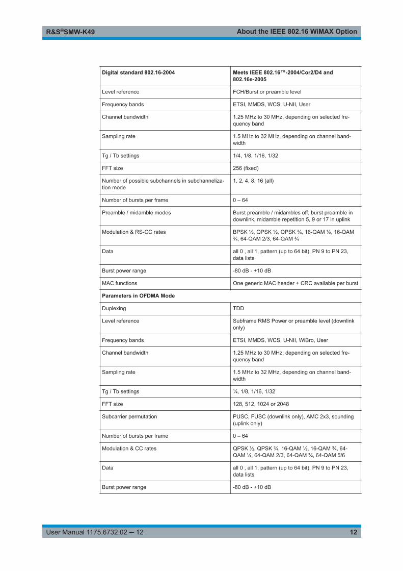
Table 3-1: Parameters of the modulation system IEEE 802.16 WiMAX
Digital standard 802.16-2004 Meets IEEE 802.16™-2004/Cor2/D4 and802.16e-2005
Physical layer modes OFDM, OFDMA, OFDMA – WiBro
Link direction forward link and reverse link
Frame durations 2, 2.5, 4, 5, 8, 10, 12.5, 20 ms, continuous, user-definable
Sequence length 1 to 511 frames (depending on frame duration)
Clipping Vector or scalar clipping, applied before filtering
Marker modes Restart, frame start, frame active part, pulse, pat-tern, on/off ratio
Parameters in OFDM Mode
Duplexing TDD, FDD
Predefined frames Short, mid and long length test messages for testingreceivers with all modulation types and RS-CC rates
About the IEEE 802.16 WiMAX OptionR&S®SMW-K49
12User Manual 1175.6732.02 ─ 12
Digital standard 802.16-2004 Meets IEEE 802.16™-2004/Cor2/D4 and802.16e-2005
Level reference FCH/Burst or preamble level
Frequency bands ETSI, MMDS, WCS, U-NII, User
Channel bandwidth 1.25 MHz to 30 MHz, depending on selected fre-quency band
Sampling rate 1.5 MHz to 32 MHz, depending on channel band-width
Tg / Tb settings 1/4, 1/8, 1/16, 1/32
FFT size 256 (fixed)
Number of possible subchannels in subchanneliza-tion mode
1, 2, 4, 8, 16 (all)
Number of bursts per frame 0 – 64
Preamble / midamble modes Burst preamble / midambles off, burst preamble indownlink, midamble repetition 5, 9 or 17 in uplink
Modulation & RS-CC rates BPSK ½, QPSK ½, QPSK ¾, 16-QAM ½, 16-QAM¾, 64-QAM 2/3, 64-QAM ¾
Data all 0 , all 1, pattern (up to 64 bit), PN 9 to PN 23,data lists
Burst power range -80 dB - +10 dB
MAC functions One generic MAC header + CRC available per burst
Parameters in OFDMA Mode
Duplexing TDD
Level reference Subframe RMS Power or preamble level (downlinkonly)
Frequency bands ETSI, MMDS, WCS, U-NII, WiBro, User
Channel bandwidth 1.25 MHz to 30 MHz, depending on selected fre-quency band
Sampling rate 1.5 MHz to 32 MHz, depending on channel band-width
Tg / Tb settings ¼, 1/8, 1/16, 1/32
FFT size 128, 512, 1024 or 2048
Subcarrier permutation PUSC, FUSC (downlink only), AMC 2x3, sounding(uplink only)
Number of bursts per frame 0 – 64
Modulation & CC rates QPSK ½, QPSK ¾, 16-QAM ½, 16-QAM ¾, 64-QAM ½, 64-QAM 2/3, 64-QAM ¾, 64-QAM 5/6
Data all 0 , all 1, pattern (up to 64 bit), PN 9 to PN 23,data lists
Burst power range -80 dB - +10 dB
About the IEEE 802.16 WiMAX OptionR&S®SMW-K49
13User Manual 1175.6732.02 ─ 12
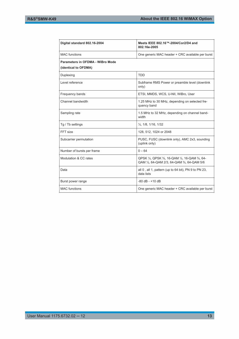
Digital standard 802.16-2004 Meets IEEE 802.16™-2004/Cor2/D4 and802.16e-2005
MAC functions One generic MAC header + CRC available per burst
Parameters in OFDMA - WiBro Mode
(identical to OFDMA)
Duplexing TDD
Level reference Subframe RMS Power or preamble level (downlinkonly)
Frequency bands ETSI, MMDS, WCS, U-NII, WiBro, User
Channel bandwidth 1.25 MHz to 30 MHz, depending on selected fre-quency band
Sampling rate 1.5 MHz to 32 MHz, depending on channel band-width
Tg / Tb settings ¼, 1/8, 1/16, 1/32
FFT size 128, 512, 1024 or 2048
Subcarrier permutation PUSC, FUSC (downlink only), AMC 2x3, sounding(uplink only)
Number of bursts per frame 0 – 64
Modulation & CC rates QPSK ½, QPSK ¾, 16-QAM ½, 16-QAM ¾, 64-QAM ½, 64-QAM 2/3, 64-QAM ¾, 64-QAM 5/6
Data all 0 , all 1, pattern (up to 64 bit), PN 9 to PN 23,data lists
Burst power range -80 dB - +10 dB
MAC functions One generic MAC header + CRC available per burst
WiMAX Configuration and SettingsR&S®SMW-K49
14User Manual 1175.6732.02 ─ 12
4 WiMAX Configuration and SettingsAccess:
► Select "Baseband > IEEE 802.16 WiMAX".
The remote commands required to define these settings are described in Chapter 5,"Remote-Control Commands", on page 124.
● General Settings for WiMAX Signals...................................................................... 14● Trigger Settings.......................................................................................................19● Marker Settings.......................................................................................................24● Clock Settings......................................................................................................... 26● Local and Global Connector Settings......................................................................28● Frame Configuration General Settings....................................................................28● Frame Configuration OFDM....................................................................................30● FCH Configuration Downlink OFDM....................................................................... 41● Generate UL-MAP Uplink OFDM............................................................................43● DL-MAP Configuration Downlink OFDM.................................................................45● UL-MAP Configuration Downlink OFDM.................................................................47● More Parameters Uplink OFDM..............................................................................48● MAC Header Configuration OFDM......................................................................... 49● Frame Configuration OFDMA................................................................................. 51● Zone Configuration OFDMA....................................................................................58● Sounding Zone Configuration OFDMA................................................................... 69● CSTD OFDMA........................................................................................................ 76● Data Configuration OFDMA.................................................................................... 78● FCH Configuration Downlink OFDMA.....................................................................86● DL-MAP Configuration Downlink OFDMA...............................................................88● UL-MAP Configuration Downlink OFDMA...............................................................94● Generate UL-MAP Uplink OFDMA..........................................................................99● Ranging Uplink OFDMA........................................................................................100● HARQ Configuration OFDMA............................................................................... 102● Fast Feedback Configuration OFDMA..................................................................109● SUB-DL-UL-MAP Configuration OFDMA.............................................................. 111● MAC Header Configuration OFDMA..................................................................... 113● PDU MAC Configuration OFDMA......................................................................... 115● Filter / Clipping Settings........................................................................................ 118
4.1 General Settings for WiMAX Signals
In this dialog, IEEE 802.16 WiMAX digital standard is enabled and reset and all thesettings for the signal in both transmission directions are made.
Access:
► Select "Baseband > IEEE 802.16 WiMAX > General".
General Settings for WiMAX Signals
WiMAX Configuration and SettingsR&S®SMW-K49
15User Manual 1175.6732.02 ─ 12
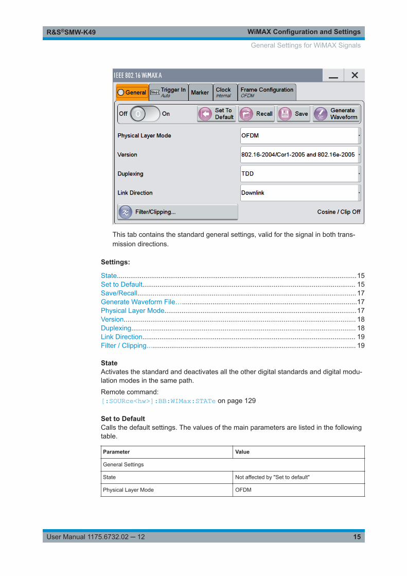
This tab contains the standard general settings, valid for the signal in both trans-mission directions.
Settings:
State..............................................................................................................................15Set to Default................................................................................................................ 15Save/Recall................................................................................................................... 17Generate Waveform File…............................................................................................17Physical Layer Mode.....................................................................................................17Version.......................................................................................................................... 18Duplexing...................................................................................................................... 18Link Direction................................................................................................................ 19Filter / Clipping.............................................................................................................. 19
StateActivates the standard and deactivates all the other digital standards and digital modu-lation modes in the same path.
Remote command: [:SOURce<hw>]:BB:WIMax:STATe on page 129
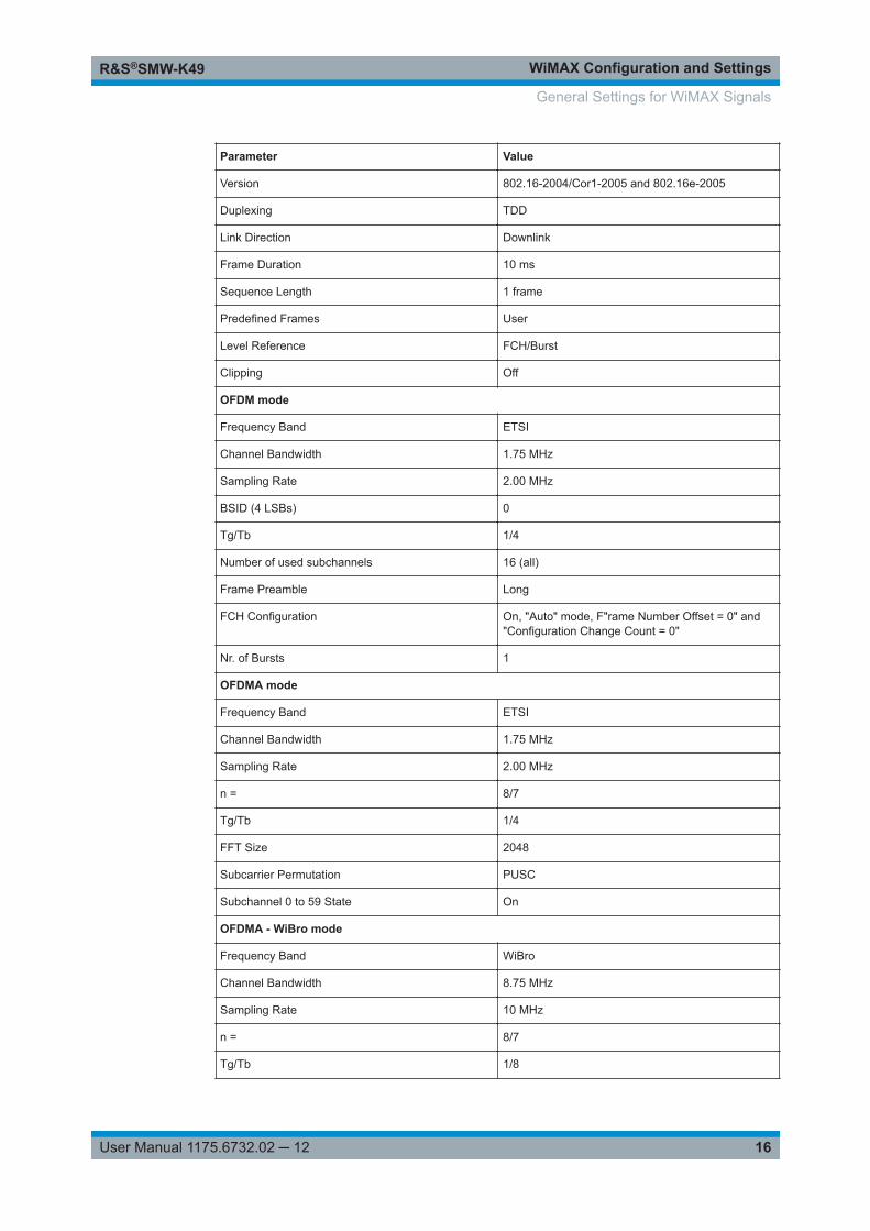
Set to DefaultCalls the default settings. The values of the main parameters are listed in the followingtable.
Parameter Value
General Settings
State Not affected by "Set to default"
Physical Layer Mode OFDM
General Settings for WiMAX Signals
WiMAX Configuration and SettingsR&S®SMW-K49
16User Manual 1175.6732.02 ─ 12
Parameter Value
Version 802.16-2004/Cor1-2005 and 802.16e-2005
Duplexing TDD
Link Direction Downlink
Frame Duration 10 ms
Sequence Length 1 frame
Predefined Frames User
Level Reference FCH/Burst
Clipping Off
OFDM mode
Frequency Band ETSI
Channel Bandwidth 1.75 MHz
Sampling Rate 2.00 MHz
BSID (4 LSBs) 0
Tg/Tb 1/4
Number of used subchannels 16 (all)
Frame Preamble Long
FCH Configuration On, "Auto" mode, F"rame Number Offset = 0" and"Configuration Change Count = 0"
Nr. of Bursts 1
OFDMA mode
Frequency Band ETSI
Channel Bandwidth 1.75 MHz
Sampling Rate 2.00 MHz
n = 8/7
Tg/Tb 1/4
FFT Size 2048
Subcarrier Permutation PUSC
Subchannel 0 to 59 State On
OFDMA - WiBro mode
Frequency Band WiBro
Channel Bandwidth 8.75 MHz
Sampling Rate 10 MHz
n = 8/7
Tg/Tb 1/8
General Settings for WiMAX Signals
WiMAX Configuration and SettingsR&S®SMW-K49
17User Manual 1175.6732.02 ─ 12
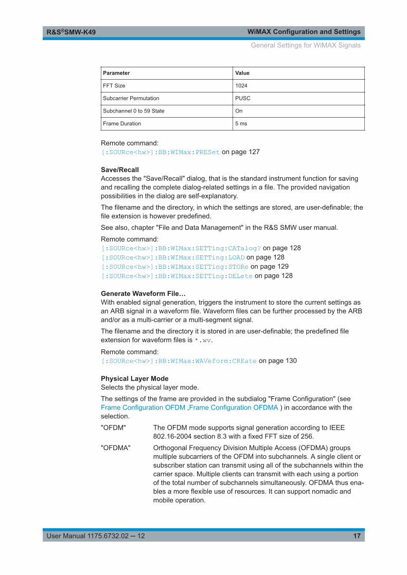
Parameter Value
FFT Size 1024
Subcarrier Permutation PUSC
Subchannel 0 to 59 State On
Frame Duration 5 ms
Remote command: [:SOURce<hw>]:BB:WIMax:PRESet on page 127
Save/RecallAccesses the "Save/Recall" dialog, that is the standard instrument function for savingand recalling the complete dialog-related settings in a file. The provided navigationpossibilities in the dialog are self-explanatory.
The filename and the directory, in which the settings are stored, are user-definable; thefile extension is however predefined.
See also, chapter "File and Data Management" in the R&S SMW user manual.
Remote command: [:SOURce<hw>]:BB:WIMax:SETTing:CATalog? on page 128[:SOURce<hw>]:BB:WIMax:SETTing:LOAD on page 128[:SOURce<hw>]:BB:WIMax:SETTing:STORe on page 129[:SOURce<hw>]:BB:WIMax:SETTing:DELete on page 128
Generate Waveform File…With enabled signal generation, triggers the instrument to store the current settings asan ARB signal in a waveform file. Waveform files can be further processed by the ARBand/or as a multi-carrier or a multi-segment signal.
The filename and the directory it is stored in are user-definable; the predefined fileextension for waveform files is *.wv.
Remote command: [:SOURce<hw>]:BB:WIMax:WAVeform:CREate on page 130
Physical Layer ModeSelects the physical layer mode.
The settings of the frame are provided in the subdialog "Frame Configuration" (seeFrame Configuration OFDM ,Frame Configuration OFDMA ) in accordance with theselection.
"OFDM" The OFDM mode supports signal generation according to IEEE802.16-2004 section 8.3 with a fixed FFT size of 256.
"OFDMA" Orthogonal Frequency Division Multiple Access (OFDMA) groupsmultiple subcarriers of the OFDM into subchannels. A single client orsubscriber station can transmit using all of the subchannels within thecarrier space. Multiple clients can transmit with each using a portionof the total number of subchannels simultaneously. OFDMA thus ena-bles a more flexible use of resources. It can support nomadic andmobile operation.
General Settings for WiMAX Signals
WiMAX Configuration and SettingsR&S®SMW-K49
18User Manual 1175.6732.02 ─ 12
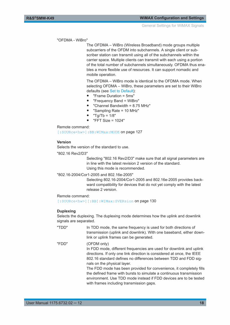
"OFDMA - WiBro"The OFDMA – WiBro (Wireless Broadband) mode groups multiplesubcarriers of the OFDM into subchannels. A single client or sub-scriber station can transmit using all of the subchannels within thecarrier space. Multiple clients can transmit with each using a portionof the total number of subchannels simultaneously. OFDMA thus ena-bles a more flexible use of resources. It can support nomadic andmobile operation.
The OFDMA – WiBro mode is identical to the OFDMA mode. Whenselecting OFDMA – WiBro, these parameters are set to their WiBrodefaults (see Set to Default):● "Frame Duration = 5ms"● "Frequency Band = WiBro"● "Channel Bandwidth = 8.75 MHz"● "Sampling Rate = 10 MHz"● "Tg/Tb = 1/8"● "FFT Size = 1024"
Remote command: [:SOURce<hw>]:BB:WIMax:MODE on page 127
VersionSelects the version of the standard to use.
"802.16 Rev2/D3"Selecting "802.16 Rev2/D3" make sure that all signal parameters arein line with the latest revision 2 version of the standard.Using this mode is recommended.
"802.16-2004/Cor1-2005 and 802.16e-2005"Selecting 802.16-2004/Cor1-2005 and 802.16e-2005 provides back-ward compatibility for devices that do not yet comply with the latestrelease 2 version.
Remote command: [:SOURce<hw>][:BB]:WIMax:SVERsion on page 130
DuplexingSelects the duplexing. The duplexing mode determines how the uplink and downlinksignals are separated.
"TDD" In TDD mode, the same frequency is used for both directions oftransmission (uplink and downlink). With one baseband, either down-link or uplink frames can be generated.
"FDD" (OFDM only)In FDD mode, different frequencies are used for downlink and uplinkdirections. If only one link direction is considered at once, the IEEE802.16 standard defines no differences between TDD and FDD sig-nals on the physical layer.The FDD mode has been provided for convenience, it completely fillsthe defined frame with bursts to simulate a continuous transmissionenvironment. Use TDD mode instead if FDD devices are to be testedwith frames including transmission gaps.
General Settings for WiMAX Signals
WiMAX Configuration and SettingsR&S®SMW-K49
19User Manual 1175.6732.02 ─ 12
Remote command: [:SOURce<hw>]:BB:WIMax:DUPLexing on page 125
Link DirectionSelects the transmission direction.
"Downlink" The transmission direction selected is base station to subscriber sta-tion. The signal corresponds to that of a base station.
"Uplink" The transmission direction selected is subscriber station to base sta-tion. The signal corresponds to that of a subscriber station.
Remote command: [:SOURce<hw>]:BB:WIMax:LINK on page 127
Filter / Clipping...Access to the dialog for setting baseband filtering, clipping and the sequence length ofthe arbitrary waveform component, see Chapter 4.29, "Filter / Clipping Settings",on page 118 .
4.2 Trigger Settings
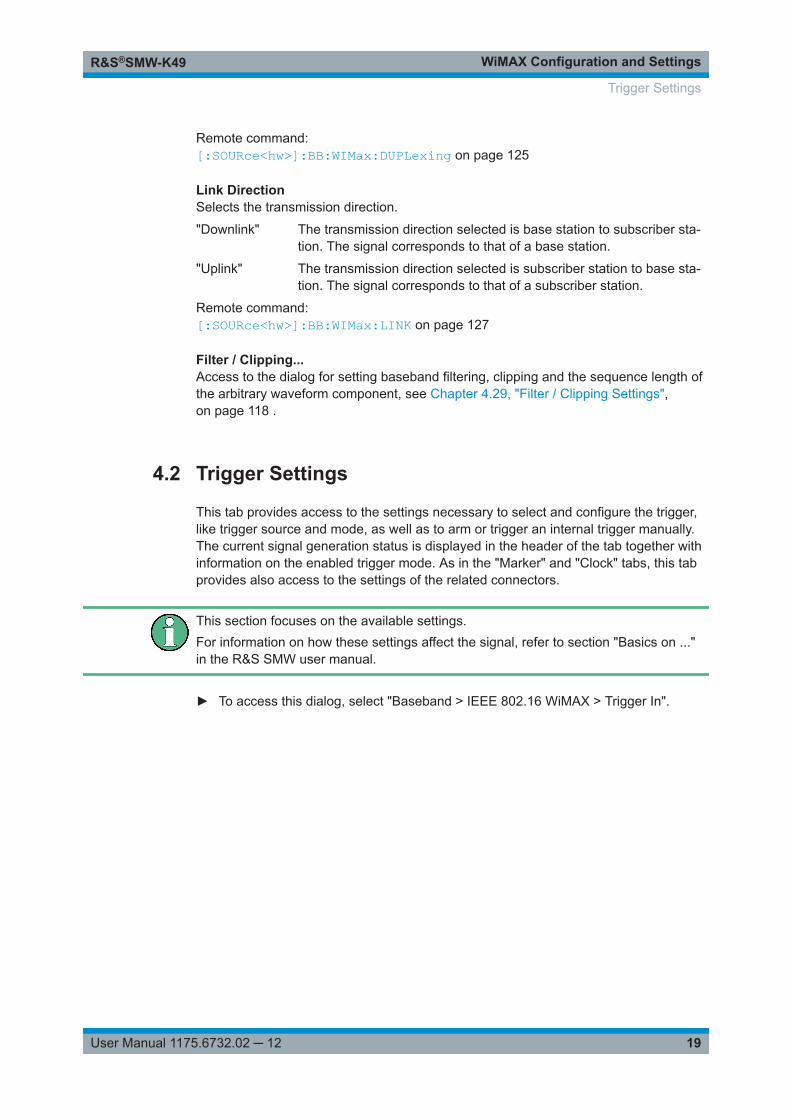
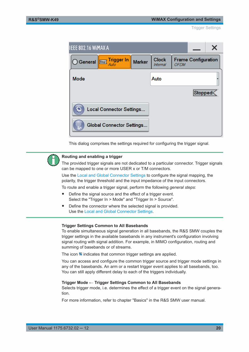
This tab provides access to the settings necessary to select and configure the trigger,like trigger source and mode, as well as to arm or trigger an internal trigger manually.The current signal generation status is displayed in the header of the tab together withinformation on the enabled trigger mode. As in the "Marker" and "Clock" tabs, this tabprovides also access to the settings of the related connectors.
This section focuses on the available settings.For information on how these settings affect the signal, refer to section "Basics on ..."in the R&S SMW user manual.
► To access this dialog, select "Baseband > IEEE 802.16 WiMAX > Trigger In".
Trigger Settings
WiMAX Configuration and SettingsR&S®SMW-K49
20User Manual 1175.6732.02 ─ 12
This dialog comprises the settings required for configuring the trigger signal.
Routing and enabling a triggerThe provided trigger signals are not dedicated to a particular connector. Trigger signalscan be mapped to one or more USER x or T/M connectors.Use the Local and Global Connector Settings to configure the signal mapping, thepolarity, the trigger threshold and the input impedance of the input connectors.To route and enable a trigger signal, perform the following general steps:● Define the signal source and the effect of a trigger event.
Select the "Trigger In > Mode" and "Trigger In > Source".● Define the connector where the selected signal is provided.
Use the Local and Global Connector Settings.
Trigger Settings Common to All BasebandsTo enable simultaneous signal generation in all basebands, the R&S SMW couples thetrigger settings in the available basebands in any instrument's configuration involvingsignal routing with signal addition. For example, in MIMO configuration, routing andsumming of basebands or of streams.
The icon indicates that common trigger settings are applied.
You can access and configure the common trigger source and trigger mode settings inany of the basebands. An arm or a restart trigger event applies to all basebands, too.You can still apply different delay to each of the triggers individually.
Trigger Mode ← Trigger Settings Common to All BasebandsSelects trigger mode, i.e. determines the effect of a trigger event on the signal genera-tion.
For more information, refer to chapter "Basics" in the R&S SMW user manual.
Trigger Settings
WiMAX Configuration and SettingsR&S®SMW-K49
21User Manual 1175.6732.02 ─ 12
● "Auto"The signal is generated continuously.
● "Retrigger"The signal is generated continuously. A trigger event (internal or external) causes arestart.
● "Armed Auto"The signal is generated only when a trigger event occurs. Then the signal is gener-ated continuously.An "Arm" stops the signal generation. A subsequent trigger event (internal with orexternal) causes a restart.
● "Armed Retrigger"The signal is generated only when a trigger event occurs. Then the signal is gener-ated continuously. Every subsequent trigger event causes a restart.An "Arm" stops signal generation. A subsequent trigger event (internal with orexternal) causes a restart.
● "Single"The signal is generated only when a trigger event occurs. Then the signal is gener-ated once to the length specified at "Signal Duration".Every subsequent trigger event (internal or external) causes a restart.
Remote command: [:SOURce<hw>]:BB:WIMax[:TRIGger]:SEQuence on page 140
Signal Duration Unit ← Trigger Settings Common to All BasebandsDefines the unit for describing the length of the signal sequence to be output in the"Single" trigger mode.
Remote command: [:SOURce<hw>]:BB:WIMax:TRIGger:SLUNit on page 139
Trigger Signal Duration ← Trigger Settings Common to All BasebandsEnters the length of the signal sequence to be output in the "Single" trigger mode.
Use this parameter to output part of the signal deliberately, an exact sequence of thesignal, or a defined number of repetitions of the signal.
Remote command: [:SOURce<hw>]:BB:WIMax:TRIGger:SLENgth on page 138
Running/Stopped ← Trigger Settings Common to All BasebandsWith enabled modulation, displays the status of signal generation for all trigger modes.● "Running"
The signal is generated; a trigger was (internally or externally) initiated in triggeredmode.
● "Stopped"The signal is not generated and the instrument waits for a trigger event.
Remote command: [:SOURce<hw>]:BB:WIMax:TRIGger:RMODe? on page 138
Arm ← Trigger Settings Common to All BasebandsStops the signal generation until subsequent trigger event occurs.
Trigger Settings
WiMAX Configuration and SettingsR&S®SMW-K49
22User Manual 1175.6732.02 ─ 12
Remote command: [:SOURce<hw>]:BB:WIMax:TRIGger:ARM:EXECute on page 137
Execute Trigger ← Trigger Settings Common to All BasebandsFor internal trigger source, executes trigger manually.
Remote command: [:SOURce<hw>]:BB:WIMax:TRIGger:EXECute on page 137
Trigger Source ← Trigger Settings Common to All BasebandsThe following sources of the trigger signal are available:● "Internal"
The trigger event is executed manually by the "Execute Trigger".● "Internal (Baseband A/B)"
The trigger event is provided by the trigger signal from the other basebands.If common trigger settings are applied, this trigger source is disabled.
● "External Global Trigger"The trigger event is the active edge of an external trigger signal provided and con-figured at the USER x connectors.
● "External Local Trigger"The trigger event is the active edge of an external trigger signal provided and con-figured at the local T/M/C connector.With coupled trigger settings, the signal has to be provided at the T/M/C1/2/3 con-nectors.
● "External Local Clock"The trigger event is the active edge of an external local clock signal provided andconfigured at the local T/M/C connector.With coupled trigger settings, the signal has to be provided at the T/M/C1 connec-tor.
Remote command: [:SOURce<hw>]:BB:WIMax:TRIGger:SOURce on page 139
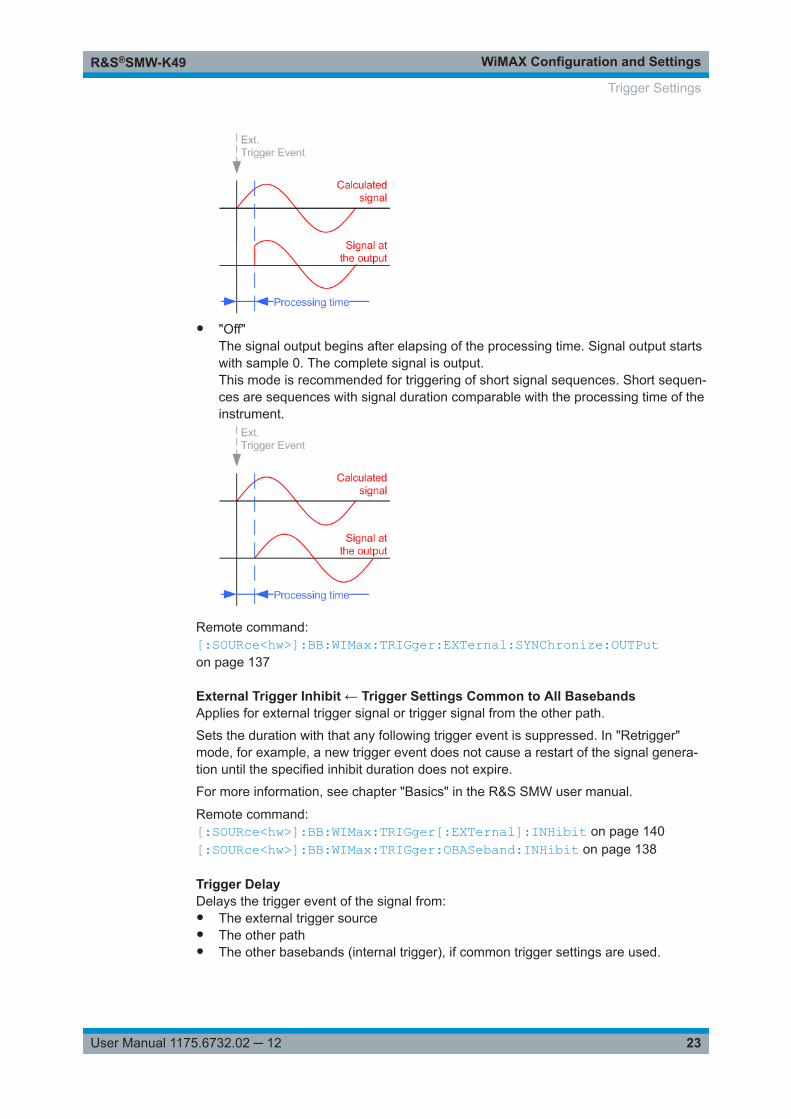
Sync. Output to External Trigger ← Trigger Settings Common to All BasebandsEnables signal output synchronous to the trigger event.● "On"
Corresponds to the default state of this parameter.The signal calculation starts simultaneously with the trigger event. Because of theprocessing time of the instrument, the first samples are cut off and no signal is out-put. After elapsing of the internal processing time, the output signal is synchronousto the trigger event.
Trigger Settings
WiMAX Configuration and SettingsR&S®SMW-K49
23User Manual 1175.6732.02 ─ 12
● "Off"The signal output begins after elapsing of the processing time. Signal output startswith sample 0. The complete signal is output.This mode is recommended for triggering of short signal sequences. Short sequen-ces are sequences with signal duration comparable with the processing time of theinstrument.
Remote command: [:SOURce<hw>]:BB:WIMax:TRIGger:EXTernal:SYNChronize:OUTPuton page 137
External Trigger Inhibit ← Trigger Settings Common to All BasebandsApplies for external trigger signal or trigger signal from the other path.
Sets the duration with that any following trigger event is suppressed. In "Retrigger"mode, for example, a new trigger event does not cause a restart of the signal genera-tion until the specified inhibit duration does not expire.
For more information, see chapter "Basics" in the R&S SMW user manual.
Remote command: [:SOURce<hw>]:BB:WIMax:TRIGger[:EXTernal]:INHibit on page 140[:SOURce<hw>]:BB:WIMax:TRIGger:OBASeband:INHibit on page 138
Trigger DelayDelays the trigger event of the signal from:● The external trigger source● The other path● The other basebands (internal trigger), if common trigger settings are used.
Trigger Settings
WiMAX Configuration and SettingsR&S®SMW-K49
24User Manual 1175.6732.02 ─ 12
Use this setting to:● Synchronize the instrument with the device under test (DUT) or other external devi-
ces● Postpone the signal generation start in the basebands compared to each otherFor more information, see chapter "Basics on ..." in the R&S SMW user manual.
Remote command: [:SOURce<hw>]:BB:WIMax:TRIGger[:EXTernal]:DELay on page 140[:SOURce<hw>]:BB:WIMax:TRIGger:OBASeband:DELay on page 138
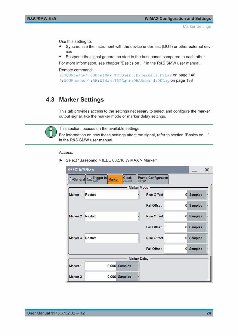
4.3 Marker Settings
This tab provides access to the settings necessary to select and configure the markeroutput signal, like the marker mode or marker delay settings.
This section focuses on the available settings.For information on how these settings affect the signal, refer to section "Basics on ..."in the R&S SMW user manual.
Access:
► Select "Baseband > IEEE 802.16 WiMAX > Marker".
Marker Settings
WiMAX Configuration and SettingsR&S®SMW-K49
25User Manual 1175.6732.02 ─ 12
This dialog comprises the settings required for configuring the marker mode andthe marker delay.
Routing and enabling a markerThe provided marker signals are not dedicated to a particular connector. They can bemapped to one or more USER x or T/M connectors.To route and enable a marker signal, perform the following general steps:● Define the shape of the generated marker, i.e. select the "Marker > Mode".● Define the connector where the selected signal is provided.
Use the Local and Global Connector Settings.
Marker ModeMarker configuration for up to 3 marker channels. The settings are used to select themarker mode defining the shape and periodicity of the markers. The contents of thedialog change with the selected marker mode; the settings are self-explanatory.
"Restart" A marker signal is generated at the start of each ARB sequence.
"Frame" A marker signal is generated at the start of each frame.
"Frame ActivePart"
The marker signal is high whenever a burst is active and low duringinactive signal parts.(Such as the gaps between bursts in uplink mode or the uplink sub-frame in downlink TDD mode).This marker can be used to decrease the carrier leakage during inac-tive signal parts by feeding it into the pulse modulator.
"Pulse" A regular marker signal is generated.
Remote command: [:SOURce<hw>]:BB:WIMax:TRIGger:OUTPut<ch>:PULSe:DIVideron page 142[:SOURce<hw>]:BB:WIMax:TRIGger:OUTPut<ch>:PULSe:FREQuency?on page 143
"Pattern " The marker signal defined as a bit pattern with a maximum length of32 bits.
Remote command: [:SOURce<hw>]:BB:WIMax:TRIGger:OUTPut<ch>:PATTern on page 142
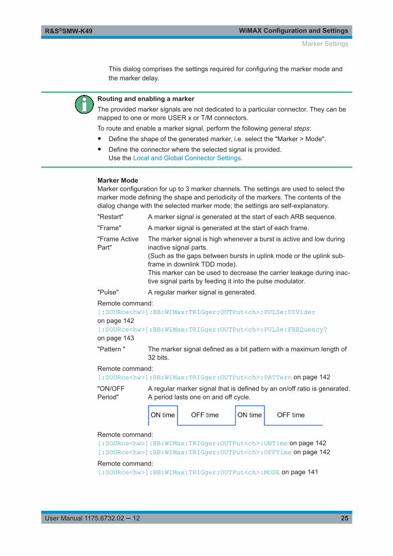
"ON/OFFPeriod"
A regular marker signal that is defined by an on/off ratio is generated.A period lasts one on and off cycle.
Remote command: [:SOURce<hw>]:BB:WIMax:TRIGger:OUTPut<ch>:ONTime on page 142[:SOURce<hw>]:BB:WIMax:TRIGger:OUTPut<ch>:OFFTime on page 142
Remote command: [:SOURce<hw>]:BB:WIMax:TRIGger:OUTPut<ch>:MODE on page 141
Marker Settings
WiMAX Configuration and SettingsR&S®SMW-K49
26User Manual 1175.6732.02 ─ 12
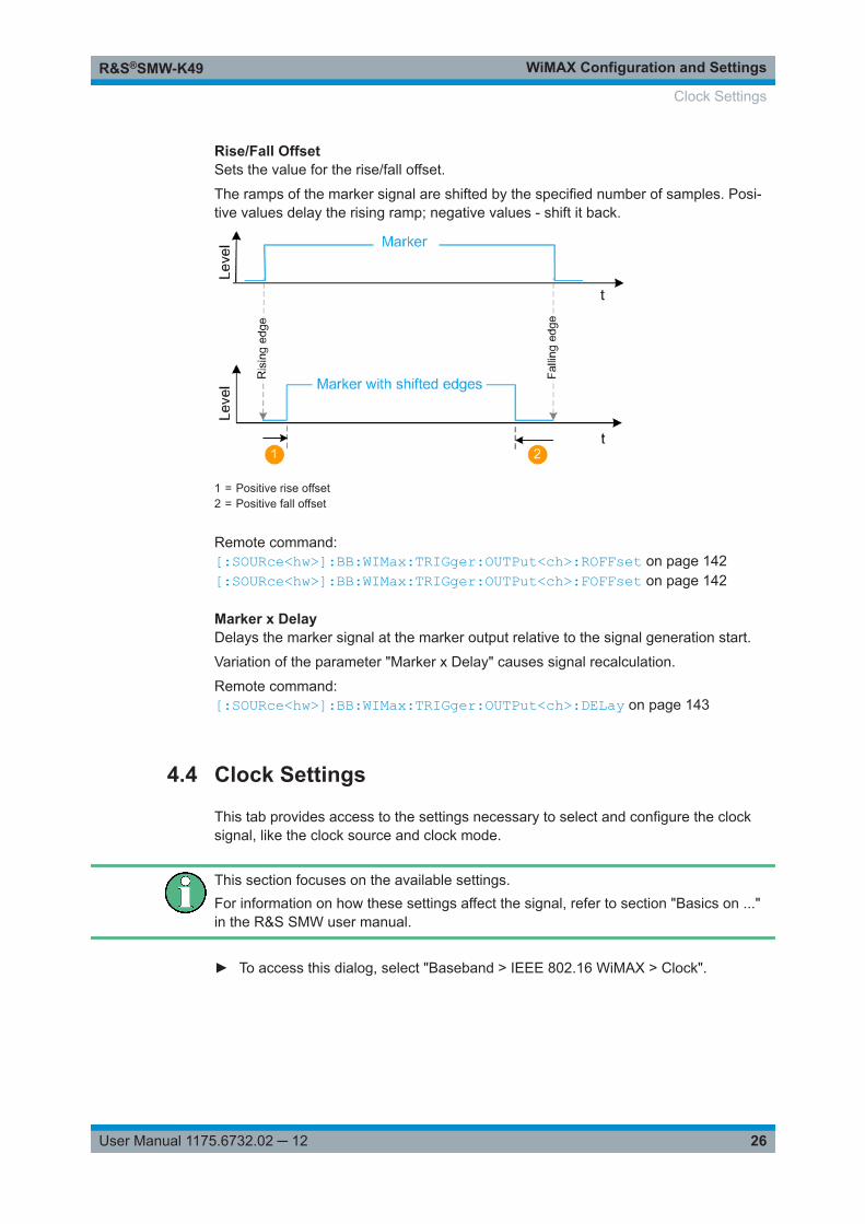
Rise/Fall OffsetSets the value for the rise/fall offset.
The ramps of the marker signal are shifted by the specified number of samples. Posi-tive values delay the rising ramp; negative values - shift it back.
1 = Positive rise offset2 = Positive fall offset
Remote command: [:SOURce<hw>]:BB:WIMax:TRIGger:OUTPut<ch>:ROFFset on page 142[:SOURce<hw>]:BB:WIMax:TRIGger:OUTPut<ch>:FOFFset on page 142
Marker x DelayDelays the marker signal at the marker output relative to the signal generation start.
Variation of the parameter "Marker x Delay" causes signal recalculation.
Remote command: [:SOURce<hw>]:BB:WIMax:TRIGger:OUTPut<ch>:DELay on page 143
4.4 Clock Settings
This tab provides access to the settings necessary to select and configure the clocksignal, like the clock source and clock mode.
This section focuses on the available settings.For information on how these settings affect the signal, refer to section "Basics on ..."in the R&S SMW user manual.
► To access this dialog, select "Baseband > IEEE 802.16 WiMAX > Clock".
Clock Settings
WiMAX Configuration and SettingsR&S®SMW-K49
27User Manual 1175.6732.02 ─ 12
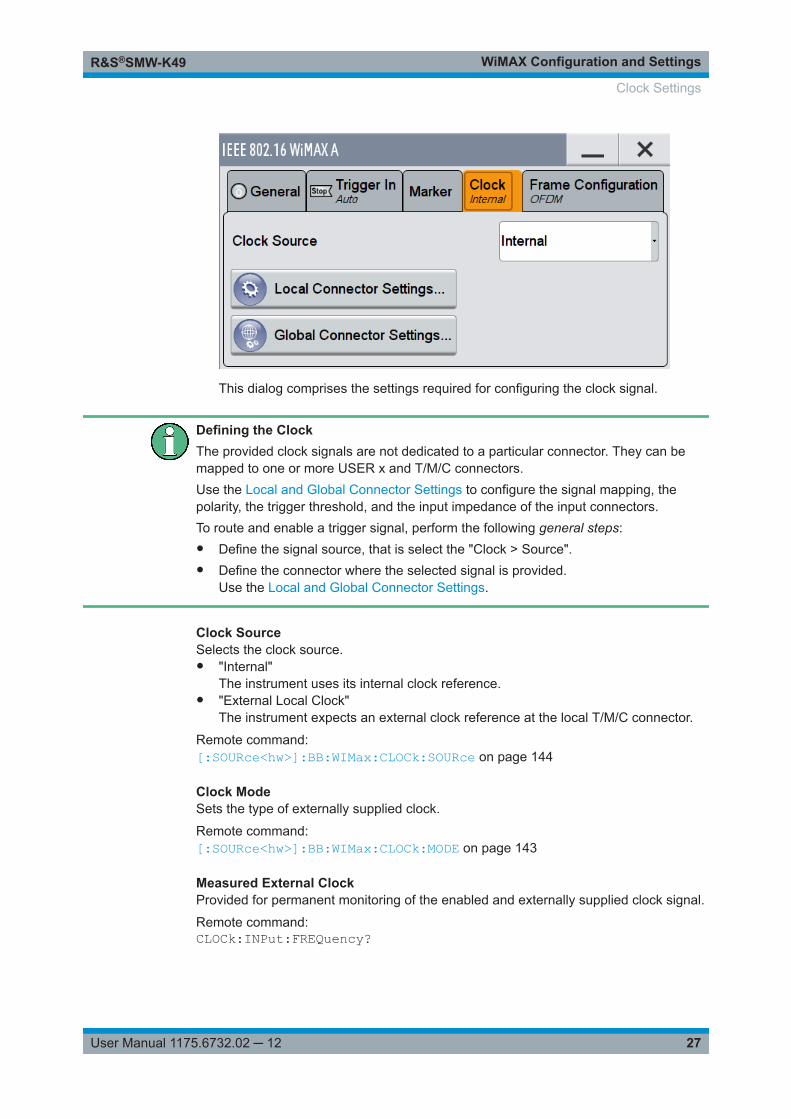
This dialog comprises the settings required for configuring the clock signal.
Defining the ClockThe provided clock signals are not dedicated to a particular connector. They can bemapped to one or more USER x and T/M/C connectors.Use the Local and Global Connector Settings to configure the signal mapping, thepolarity, the trigger threshold, and the input impedance of the input connectors.To route and enable a trigger signal, perform the following general steps:● Define the signal source, that is select the "Clock > Source".● Define the connector where the selected signal is provided.
Use the Local and Global Connector Settings.
Clock SourceSelects the clock source.● "Internal"
The instrument uses its internal clock reference.● "External Local Clock"
The instrument expects an external clock reference at the local T/M/C connector.
Remote command: [:SOURce<hw>]:BB:WIMax:CLOCk:SOURce on page 144
Clock ModeSets the type of externally supplied clock.
Remote command: [:SOURce<hw>]:BB:WIMax:CLOCk:MODE on page 143
Measured External ClockProvided for permanent monitoring of the enabled and externally supplied clock signal.
Remote command: CLOCk:INPut:FREQuency?
Clock Settings
WiMAX Configuration and SettingsR&S®SMW-K49
28User Manual 1175.6732.02 ─ 12
4.5 Local and Global Connector Settings
Each of the "Trigger In", "Marker" and "Clock" dialogs as well as the "Trigger MarkerClock" dialog provides a quick access to the related connector settings.
For more information, refer to the description R&S SMW user manual, section "Localand Global Connector Settings".
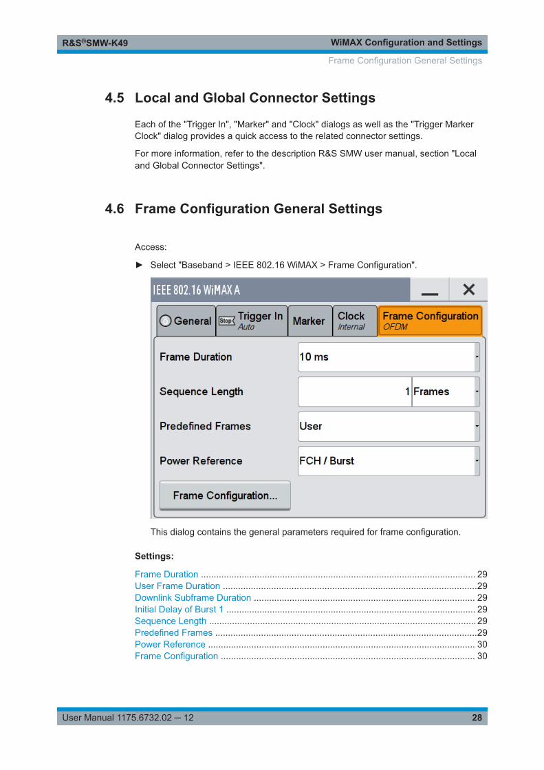
4.6 Frame Configuration General Settings
Access:
► Select "Baseband > IEEE 802.16 WiMAX > Frame Configuration".
This dialog contains the general parameters required for frame configuration.
Settings:
Frame Duration ............................................................................................................ 29User Frame Duration ....................................................................................................29Downlink Subframe Duration ....................................................................................... 29Initial Delay of Burst 1 .................................................................................................. 29Sequence Length ......................................................................................................... 29Predefined Frames .......................................................................................................29Power Reference ......................................................................................................... 30Frame Configuration .................................................................................................... 30
Frame Configuration General Settings
WiMAX Configuration and SettingsR&S®SMW-K49
29User Manual 1175.6732.02 ─ 12
Frame DurationSelects the frame duration.
Only distinct values are allowed in the standard. For test reasons, continuous genera-tion or generation for a freely selectable duration (User) are available. In continuousmode, the frame duration equals the sum of the burst durations in OFDM mode or thesubframe duration in OFDMA mode.
Remote command: [:SOURce<hw>]:BB:WIMax:FRAMe:TIME on page 126
User Frame Duration(available for Frame Duration set to User)
Sets the frame duration for selection User. The values are freely selectable.
Remote command: [:SOURce<hw>]:BB:WIMax:FRAMe:TIME:USER on page 127
Downlink Subframe Duration(available for uplink direction in TDD mode)
Delays the first uplink burst by the set time duration.
Remote command: [:SOURce<hw>]:BB:WIMax:SUBFrame:TIME on page 130
Initial Delay of Burst 1(available for the uplink direction in FDD mode with physical layer mode OFDM)
Delays the first uplink burst by the set time duration.
In FDD mode, this parameter is provided for convenience to enable a constant delay ofthe signal with respect to an internal or external frame trigger.
Remote command: [:SOURce<hw>]:BB:WIMax:FRAMe:BURSt:DELay on page 126
Sequence LengthSets the sequence length of the signal in number of frames. The signal is calculated inadvance and output in the arbitrary waveform generator. Burst data sources are contin-uously read over the whole sequence length.
Remote command: [:SOURce<hw>]:BB:WIMax:SLENgth on page 129
Predefined FramesSelects the frame type.
"Test Message BPSK 1/2 Short, Test Message BPSK 1/2 Mid,…(OFDM only)"Predefined setups for receiver test messages according to IEEE802.16-2004 section 8.3.11
"Downlink/Uplink 35MHz QPSK 1/2, Downlink/Uplink 35MHz QPSK 3/4,…(OFDMA/OFDMA-WiBro only)"
Predefined setups for receiver test messages. The available prede-fined frames depend on the selected link direction.
"User" The settings for the frame can be defined.
Frame Configuration General Settings
WiMAX Configuration and SettingsR&S®SMW-K49
30User Manual 1175.6732.02 ─ 12
Remote command: [:SOURce<hw>]:BB:WIMax:OFDM:FRAMe:PREDefined on page 221[:SOURce<hw>]:BB:WIMax:AOFDm:FRAMe:PREDefined on page 149
Power ReferenceSelects the power reference.
"FCH / Burst(OFDM only)"
The instrument's level setting refers to the mean power of FCH(Frame Control Header) or bursts with a burst power setting of 0 dB.To obtain the absolute burst power value, the burst power value hasto be added to the level value.
"Preamble (OFDM uplink and downlink OFDMA/OFDMA - WiBro downlink only)"The instrument's level setting refers to the preamble, which isFCH / Burst power + 3dB in OFDM mode.
"Subframe RMS Power (OFDMA/OFDMA - WiBro only)"The instrument's level setting refers to the rms power of the sub-frame. This includes the preamble and all symbols with allocated car-riers in downlink or the whole uplink subframe in uplink.
"Subframe RMS Power w/o Preamble (OFDMA/OFDMA - WiBro only)"The instrument's level setting refers to the rms power of the sub-frame, excluding the preamble. This includes all symbols with alloca-ted carriers in downlink or the whole uplink subframe in uplink.
Remote command: [:SOURce<hw>]:BB:WIMax:OFDM:POWer:REFerence on page 222[:SOURce<hw>]:BB:WIMax:AOFDm:POWer:REFerence on page 151
Frame ConfigurationAccesses the dialog for configuration of the frame.
The dialog depends on the selected physical layer mode, see Chapter 4.7, "FrameConfiguration OFDM", on page 30 and Chapter 4.14, "Frame Configuration OFDMA",on page 51.
Remote command: n.a.
4.7 Frame Configuration OFDM
This dialog provides all parameters to configure frames in OFDM mode. The selectedlink direction determines the available parameters.
Access:
1. Select "General > Physical Layer Mode > OFDM".
2. Select "Frame Configuration (OFDM) > Frame Configuration"
Frame Configuration OFDM
WiMAX Configuration and SettingsR&S®SMW-K49
31User Manual 1175.6732.02 ─ 12
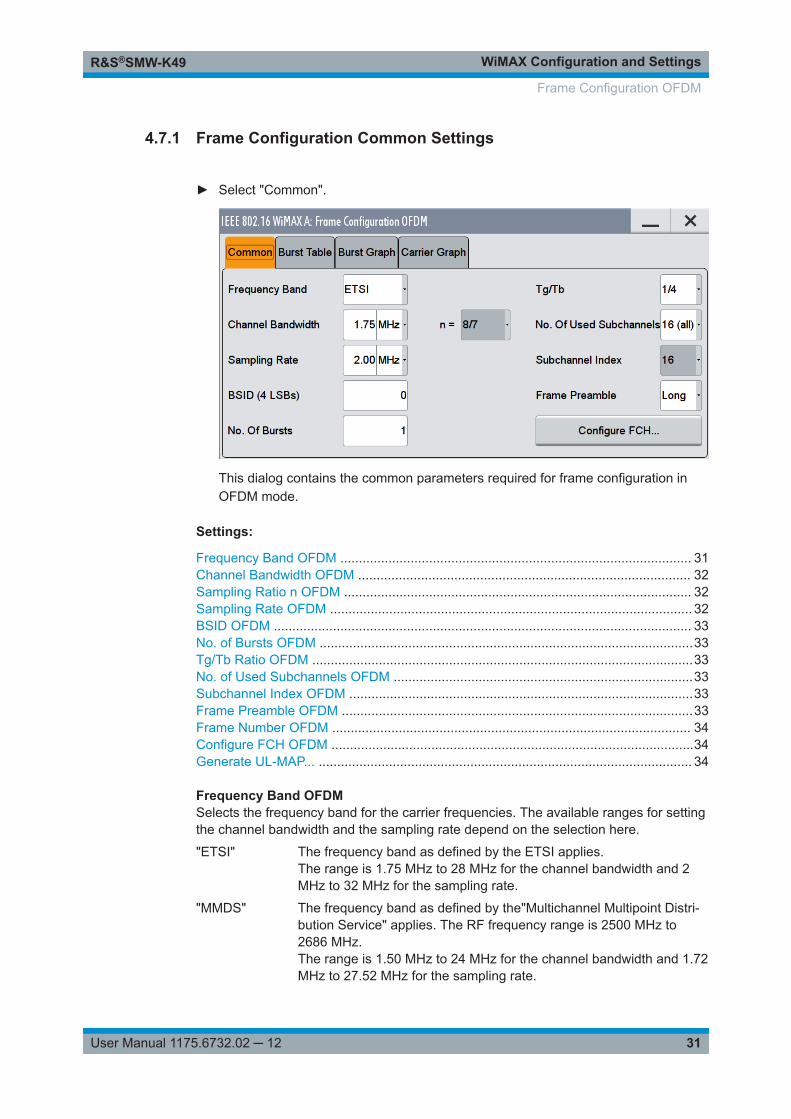
4.7.1 Frame Configuration Common Settings
► Select "Common".
This dialog contains the common parameters required for frame configuration inOFDM mode.
Settings:
Frequency Band OFDM ............................................................................................... 31Channel Bandwidth OFDM .......................................................................................... 32Sampling Ratio n OFDM .............................................................................................. 32Sampling Rate OFDM .................................................................................................. 32BSID OFDM ................................................................................................................. 33No. of Bursts OFDM .....................................................................................................33Tg/Tb Ratio OFDM .......................................................................................................33No. of Used Subchannels OFDM .................................................................................33Subchannel Index OFDM .............................................................................................33Frame Preamble OFDM ...............................................................................................33Frame Number OFDM ................................................................................................. 34Configure FCH OFDM ..................................................................................................34Generate UL-MAP... ..................................................................................................... 34
Frequency Band OFDMSelects the frequency band for the carrier frequencies. The available ranges for settingthe channel bandwidth and the sampling rate depend on the selection here.
"ETSI" The frequency band as defined by the ETSI applies.The range is 1.75 MHz to 28 MHz for the channel bandwidth and 2MHz to 32 MHz for the sampling rate.
"MMDS" The frequency band as defined by the"Multichannel Multipoint Distri-bution Service" applies. The RF frequency range is 2500 MHz to2686 MHz.The range is 1.50 MHz to 24 MHz for the channel bandwidth and 1.72MHz to 27.52 MHz for the sampling rate.
Frame Configuration OFDM
WiMAX Configuration and SettingsR&S®SMW-K49
32User Manual 1175.6732.02 ─ 12
"WCS" The frequency band as defined by the "Wireless Communication Ser-vice" applies. It is in the 2.3 GHz band of the electromagnetic spec-trum from 2305 MHz to 2320 MHz and 2345 MHz to 2360 MHz.The range is 2.5 MHz to 15 MHz for the channel bandwidth and 2.88MHz to 17.28 MHz for the sampling rate.
"U-NII" The frequency band as defined by the "Unlicensed National Informa-tion Infrastructure" applies. It is in the 5 GHz band of the electromag-netic spectrum from 5150 GHz to 5350 GHz and 5750 GHz to 5825GHz.The range is 10 MHz to 20 MHz for the channel bandwidth and 11.52MHz to 23.04 MHz for the sampling rate.
"User" This mode is provided for choosing any other channel bandwidth /sampling rate combination.The range is 1.25 MHz to 28 MHz for the channel bandwidth and 1.44MHz to 32 MHz for the sampling rate.
Remote command: [:SOURce<hw>]:BB:WIMax:OFDM:FBANd on page 218
Channel Bandwidth OFDMSets the channel bandwidth. The range is 1.25 MHz to 28 MHz.
The selected channel bandwidth has to be a multiple of 1.25, 1.5, 1.75, 2.0 MHz or2.75 MHz. The channel bandwidth determines the parameter n (see Sampling Ratio nOFDM ):● For channel bandwidths:
– A multiple of 1.75 MHz then n = 8/7– A multiple of 1.5 MHz then n = 86/75– A multiple of 1.25 MHz then n = 144/125– A multiple of 2.75 MHz then n = 316/275– A multiple of 2.0 MHz then n = 57/50
● Else for channel bandwidths not otherwise specified then n = 8/7The sampling rate is derived from the channel bandwidth as follows:
SamplingRate = floor(n * ChannelBandwidth / 8000) * 8000
Remote command: [:SOURce<hw>]:BB:WIMax:OFDM:BW on page 217
Sampling Ratio n OFDMIndicates the sampling ratio. The sampling ratio is determined by the channel band-width (see Channel Bandwidth OFDM ).
Remote command: [:SOURce<hw>]:BB:WIMax:OFDM:N? on page 222
Sampling Rate OFDMSets the sampling rate. The possible settings depend on the selected frequency band.The full range in "User" mode is 1.44 MHz to 32 MHz.
The sampling rate is related to the channel bandwidth by the parameter n:
SamplingRate = floor(n * ChannelBandwidth / 8000) * 8000
Frame Configuration OFDM
WiMAX Configuration and SettingsR&S®SMW-K49
33User Manual 1175.6732.02 ─ 12
Remote command: [:SOURce<hw>]:BB:WIMax:OFDM:SRATe on page 223
BSID OFDMSets the 4 LSBs of the Base Station ID.
The BSID is transmitted in the FCH (when set to "Auto" mode), and it is used to initial-ize the randomizer.
Remote command: [:SOURce<hw>]:BB:WIMax:OFDM:BSID on page 208
No. of Bursts OFDMSets the number of active bursts in one frame.
With number of bursts = 0, a preamble only or a preamble with an FCH burst is gener-ated.
Remote command: [:SOURce<hw>]:BB:WIMax:OFDM:BURSt[:COUNt] on page 217
Tg/Tb Ratio OFDMSelects the ratio of guard period to symbol period.
This value sets the length of the cyclic prefix in fractions of the symbol period.
Remote command: [:SOURce<hw>]:BB:WIMax:OFDM:TGTB on page 225
No. of Used Subchannels OFDMSelects the number of used subchannels.
Selection 16 (all) deactivates subchannelization and activates all possible carriers. Thevalues 1, 2, 4 and 8 activate only a part of the available subcarriers, unused carriersare blanked.
Remote command: [:SOURce<hw>]:BB:WIMax:OFDM:SUBChannel[:COUNt] on page 224
Subchannel Index OFDMSelects the subchannel index in subchannelization mode.
The subchannel index determines the set of used subcarriers according to IEEE802.16-2004.
Remote command: [:SOURce<hw>]:BB:WIMax:OFDM:SUBChannel:INDex on page 224
Frame Preamble OFDMActivates the generation of a frame preamble. Either a long preamble or a short pream-ble can be activated.
The 802.16 standard requires a long preamble as frame start.
Remote command: [:SOURce<hw>]:BB:WIMax:OFDM:PREamble:MODE on page 223
Frame Configuration OFDM
WiMAX Configuration and SettingsR&S®SMW-K49
34User Manual 1175.6732.02 ─ 12
Frame Number OFDMSelects the frame number of the uplink frame in which the UL map that specifies theuplink burst was transmitted.
Remote command: [:SOURce<hw>]:BB:WIMax:OFDM:FRAMe[:NUMBer] on page 222
Configure FCH OFDMAccesses the dialog for configuring FCH mode and parameters (see Chapter 4.8,"FCH Configuration Downlink OFDM", on page 41).
Remote command: n.a.
Generate UL-MAP...Accesses the dialog for generating the UL-Map, see Chapter 4.11, "UL-MAP Configu-ration Downlink OFDM", on page 47.
Remote command: n.a.
4.7.2 Burst Table
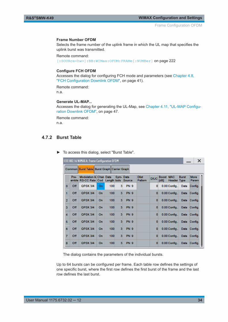
► To access this dialog, select "Burst Table".
The dialog contains the parameters of the individual bursts.
Up to 64 bursts can be configured per frame. Each table row defines the settings ofone specific burst, where the first row defines the first burst of the frame and the lastrow defines the last burst.
Frame Configuration OFDM
WiMAX Configuration and SettingsR&S®SMW-K49
35User Manual 1175.6732.02 ─ 12
For both transmission directions, different modulations and channel coding rates areavailable for each burst. A generic MAC header with encrypted payload and checksumdetermination can be activated.
Some setting parameters vary depending on the transmission direction.
Burst Index OFDMDisplays the consecutive burst index from 0 to 63.
All the rows are always displayed, even if the bursts are inactive. They are switched onand off by the selection of "No. of Bursts" above the table. The active bursts are high-lighted.
Remote command: n.a.(selected via the suffix to the keyword BURSt<n>)
Preamble OFDMEnables generation of the burst preamble.
If activated, a preamble is placed before the burst. Long or short preambles are availa-ble. The preamble has the same power as the burst. If subchannelization is used, asubchannelization preamble is generated accordingly.
Remote command: [:SOURce<hw>]:BB:WIMax:OFDM:BURSt<ch0>:PREamble:MODE on page 215
Midamble Repetition OFDMActivates midamble repetition.
If midamble repetition is switched on, midambles are placed into the burst with thespecified interval, i.e. if 5 is selected, every 5th symbol of the burst is a midamble.
A short preamble is used as midamble when subchannelization is off or a subchanneli-zation preamble is used in subchannelization mode. The power of the midambles isidentical to the burst power.
Remote command: [:SOURce<hw>]:BB:WIMax:OFDM:BURSt<ch0>:MIDamble on page 214
Modulation and RS-CC Rate OFDMSelects the modulation and channel coding rate. Channel coding includes randomiza-tion, Reed-Solomon coding, convolutional coding and interleaving.
For a given modulation type and channel coding rate, the data length determines thenumber of symbols and vice versa.
Remote command: [:SOURce<hw>]:BB:WIMax:OFDM:BURSt<ch0>:FORMat on page 212
Channel Coding OFDMSwitches channel coding on or off.
If channel coding is switched off, the bits read from the data source are directly modu-lated onto the carriers. Due to randomization missing, this could result in high crest fac-tors of the signal.
Frame Configuration OFDM
WiMAX Configuration and SettingsR&S®SMW-K49
36User Manual 1175.6732.02 ─ 12
Remote command: [:SOURce<hw>]:BB:WIMax:OFDM:BURSt<ch0>:CCODing:STATe on page 208
Data Length OFDMDetermines the data length in bytes.
The given number of bytes is read from the data source. The total number of databytes in the burst (before channel coding) is determined as follows:
TotalDataBytes = DataLength + MACHeaderBytes + CRCBytes + TailByte
The tail byte is only added when channel coding is switched on. The same is the casefor the MAC header and CRC, they are not added when switched off. Additionally pad-ding with 0xFF bytes is applied at the end of the data sequence to reach an integernumber of OFDM symbols.
The data length determines the number of symbols and vice versa. The maximum datalength of 10000 bytes defines the maximum number of symbols for a given modulationtype and channel coding rate.
Remote command: [:SOURce<hw>]:BB:WIMax:OFDM:BURSt<ch0>:DLENgth on page 210
Number of Symbols OFDMEnters the number of symbols for the selected burst. If the number of symbols ischanged, the data length is adjusted to fill the specified number of symbols with dataso that no padding has to be applied.
The maximum data length of 10 000 bytes defines the maximum number of symbolsfor a given modulation type and channel coding rate.
Remote command: [:SOURce<hw>]:BB:WIMax:OFDM:BURSt<ch0>:SYMBol[:COUNt] on page 216
Data Source OFDMSelects data source for the selected bursts.
The following standard data sources are available:● "All 0, All 1"
An internally generated sequence containing 0 data or 1 data.● "PNxx"
An internally generated pseudo-random noise sequence.● "Pattern"
An internally generated sequence according to a bit pattern.Use the "Pattern" box to define the bit pattern.
● "Data List/Select DList"A binary data from a data list, internally or externally generated.Select "Select DList" to access the standard "Select List" dialog.– Select the "Select Data List > navigate to the list file *.dm_iqd > Select" to
select an existing data list.– Use the "New" and "Edit" functions to create internally new data list or to edit
an existing one.– Use the standard "File Manager" function to transfer external data lists to the
instrument.
Frame Configuration OFDM
WiMAX Configuration and SettingsR&S®SMW-K49
37User Manual 1175.6732.02 ─ 12
See also:● Section "Modulation Data" in the R&S SMW user manual.● Section "File and Data Management" in the R&S SMW user manual.● Section "Data List Editor" in the R&S SMW user manual
Remote command: [:SOURce<hw>]:BB:WIMax:OFDM:BURSt<ch0>:DATA on page 209[:SOURce<hw>]:BB:WIMax:OFDM:BURSt<ch0>:DATA:PATTern on page 210[:SOURce<hw>]:BB:WIMax:OFDM:BURSt<ch0>:DATA:DSELect on page 209
DIUC OFDMSets the specific interval usage code.
The code is used to initialize the randomizer.
Remote command: [:SOURce<hw>]:BB:WIMax:OFDM:BURSt<ch0>:DIUC on page 210
Boost OFDMSets the burst power in dB.
To set the absolute power of a burst correctly, level reference "FCH / Burst" must beselected. In this mode, the output power of a burst is calculated as the sum of the"Level" and the burst power.
In downlink, the preamble is transmitted with +3 dB and the FCH is transmitted with 0dB.
In uplink, the power of the first burst is fixed to 0 dB.
Remote command: [:SOURce<hw>]:BB:WIMax:OFDM:BURSt<ch0>:POWer on page 215
MAC Header OFDMCalls the dialog for configuring the generic MAC (Media Access Control) header of theselected burst and for activating the checksum determination.
Remote command: n.a.
Burst Type OFDMSelect the burst type.
"Date" Regular bursts are called "Data" bursts. All data sources are availablefor this type of burst.
Frame Configuration OFDM
WiMAX Configuration and SettingsR&S®SMW-K49
38User Manual 1175.6732.02 ─ 12
"DL-MAP" A DL-MAP is generated, considering all active bursts.
The DL-MAP fields are filled with the following parameters:● [DCD Count]● Set to "Configuration Change Count" from the FCH panel● "Base Station ID"
Set to BSID from the Frame Configuration panel● "CID"
Set to CID from the MAC header panel for each burst● "DIUC"
Set to DIUC from the burst table for each burst● "Preamble present"
Set to 1 if a burst preamble is present● "Start Time"
Set to burst start time in OFDM symbols, relative to frame start
"UL-MAP" A UL-MAP is generated using the specified data list, including addi-tional parameters from the "More Param" panel. See Generate UL-MAP... for more information on how to create UL-MAP bursts.
"Ranging" An uplink ranging burst is composed of a long preamble following twosubchannelized preambles using one active subchannel. The sub-channel index for the two preambles is read from the configured datasource. For each frame, 4 bits are read from the data source (called"data"), which define the subchannel index as follows:Index = data * 2 + 1
Remote command: [:SOURce<hw>]:BB:WIMax:OFDM:BURSt<ch0>:TYPE on page 216
More Parameter OFDM – WiMAXAccesses the dialog for configuring additional parameters for the bursts, see Chap-ter 4.12, "More Parameters Uplink OFDM", on page 48.
Remote command: n.a.
Gap OFDMSets the length of the gap between the selected burst and the next burst in µs. Thesetting is only available for transmission direction uplink.
Remote command: [:SOURce<hw>]:BB:WIMax:OFDM:BURSt<ch0>:GAP on page 212
4.7.3 Frame Burst Graph OFDM
► To access this dialog, select "Burst Graph".
Frame Configuration OFDM
WiMAX Configuration and SettingsR&S®SMW-K49
39User Manual 1175.6732.02 ─ 12
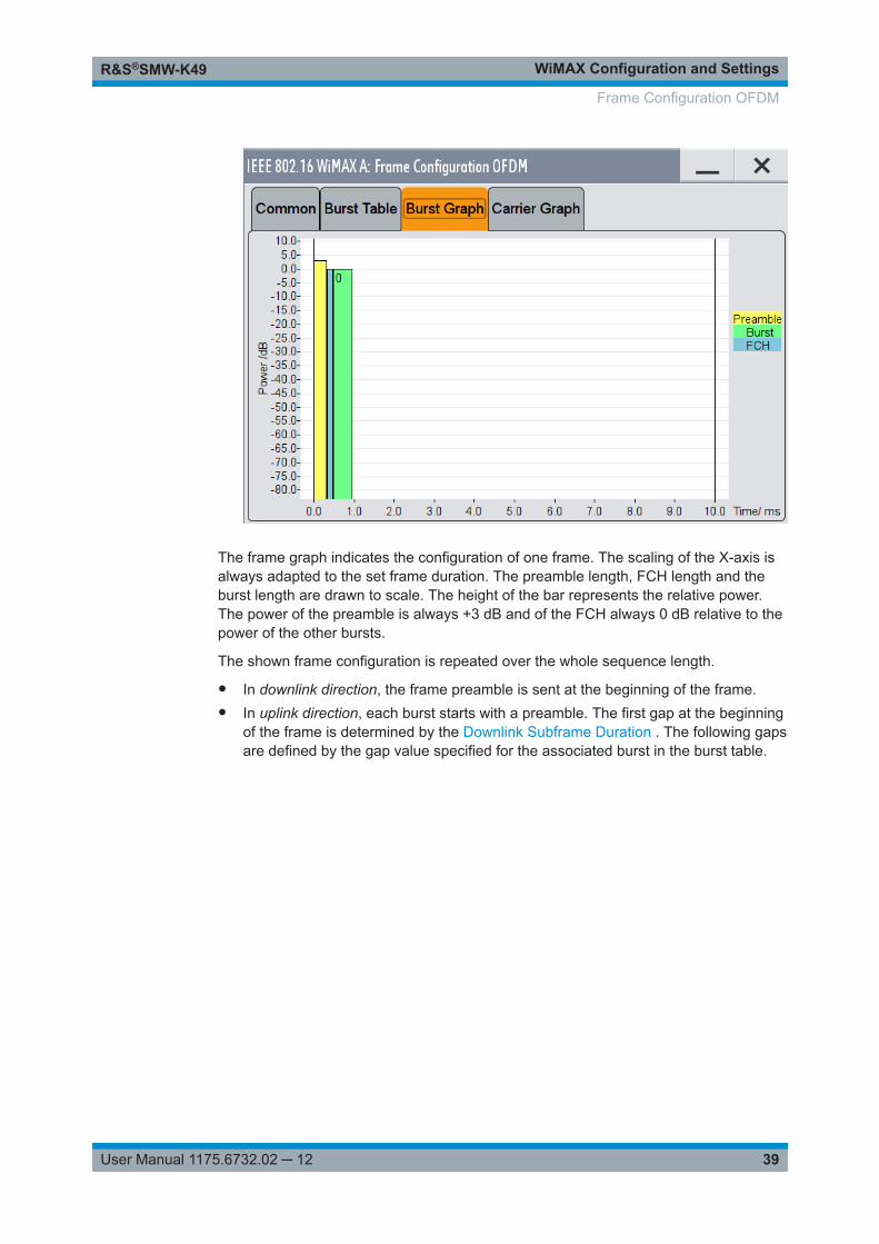
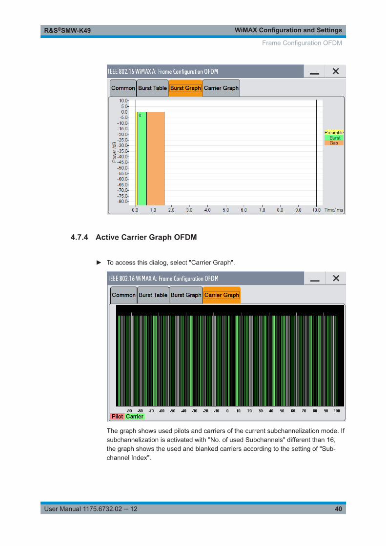
The frame graph indicates the configuration of one frame. The scaling of the X-axis isalways adapted to the set frame duration. The preamble length, FCH length and theburst length are drawn to scale. The height of the bar represents the relative power.The power of the preamble is always +3 dB and of the FCH always 0 dB relative to thepower of the other bursts.
The shown frame configuration is repeated over the whole sequence length.
● In downlink direction, the frame preamble is sent at the beginning of the frame.● In uplink direction, each burst starts with a preamble. The first gap at the beginning
of the frame is determined by the Downlink Subframe Duration . The following gapsare defined by the gap value specified for the associated burst in the burst table.
Frame Configuration OFDM
WiMAX Configuration and SettingsR&S®SMW-K49
40User Manual 1175.6732.02 ─ 12
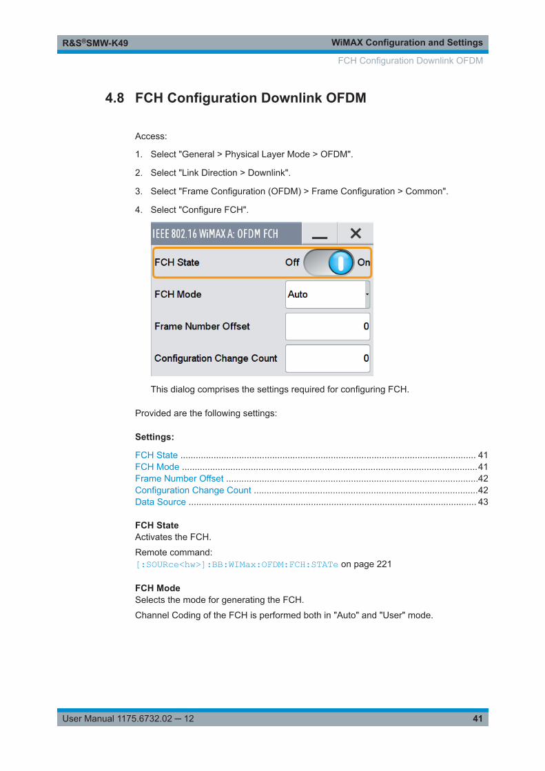
4.7.4 Active Carrier Graph OFDM
► To access this dialog, select "Carrier Graph".
The graph shows used pilots and carriers of the current subchannelization mode. Ifsubchannelization is activated with "No. of used Subchannels" different than 16,the graph shows the used and blanked carriers according to the setting of "Sub-channel Index".
Frame Configuration OFDM
WiMAX Configuration and SettingsR&S®SMW-K49
41User Manual 1175.6732.02 ─ 12
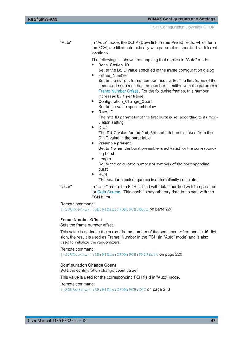
4.8 FCH Configuration Downlink OFDM
Access:
1. Select "General > Physical Layer Mode > OFDM".
2. Select "Link Direction > Downlink".
3. Select "Frame Configuration (OFDM) > Frame Configuration > Common".
4. Select "Configure FCH".
This dialog comprises the settings required for configuring FCH.
Provided are the following settings:
Settings:
FCH State .................................................................................................................... 41FCH Mode ....................................................................................................................41Frame Number Offset ...................................................................................................42Configuration Change Count ........................................................................................42Data Source ................................................................................................................. 43
FCH StateActivates the FCH.
Remote command: [:SOURce<hw>]:BB:WIMax:OFDM:FCH:STATe on page 221
FCH ModeSelects the mode for generating the FCH.
Channel Coding of the FCH is performed both in "Auto" and "User" mode.
FCH Configuration Downlink OFDM
WiMAX Configuration and SettingsR&S®SMW-K49
42User Manual 1175.6732.02 ─ 12
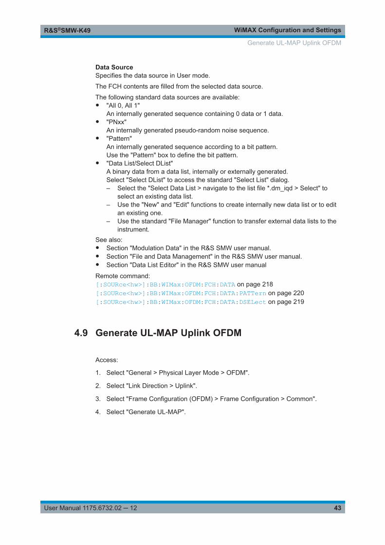
"Auto" In "Auto" mode, the DLFP (Downlink Frame Prefix) fields, which formthe FCH, are filled automatically with parameters specified at differentlocations.
The following list shows the mapping that applies in "Auto" mode:● Base_Station_ID
Set to the BSID value specified in the frame configuration dialog● Frame_Number
Set to the current frame number modulo 16. The first frame of thegenerated sequence has the number specified with the parameterFrame Number Offset . For the following frames, this numberincreases by 1 per frame
● Configuration_Change_CountSet to the value specified below
● Rate_IDThe rate ID parameter of the first burst is set according to its mod-ulation setting
● DIUCThe DIUC value for the 2nd, 3rd and 4th burst is taken from theDIUC value in the burst table
● Preamble presentSet to 1 when the burst preamble is activated for the correspond-ing burst
● LengthSet to the calculated number of symbols of the correspondingburst
● HCSThe header check sequence is automatically calculated
"User" In "User" mode, the FCH is filled with data specified with the parame-ter Data Source . This enables any arbitrary data to be sent with theFCH burst.
Remote command: [:SOURce<hw>]:BB:WIMax:OFDM:FCH:MODE on page 220
Frame Number OffsetSets the frame number offset.
This value is added to the current frame number of the sequence. After modulo 16 divi-sion, the result is used as Frame_Number in the FCH (in "Auto" mode) and is alsoused to initialize the randomizers.
Remote command: [:SOURce<hw>]:BB:WIMax:OFDM:FCH:FNOFfset on page 220
Configuration Change CountSets the configuration change count value.
This value is used for the corresponding FCH field in "Auto" mode.
Remote command: [:SOURce<hw>]:BB:WIMax:OFDM:FCH:CCC on page 218
FCH Configuration Downlink OFDM
WiMAX Configuration and SettingsR&S®SMW-K49
43User Manual 1175.6732.02 ─ 12
Data SourceSpecifies the data source in User mode.
The FCH contents are filled from the selected data source.
The following standard data sources are available:● "All 0, All 1"
An internally generated sequence containing 0 data or 1 data.● "PNxx"
An internally generated pseudo-random noise sequence.● "Pattern"
An internally generated sequence according to a bit pattern.Use the "Pattern" box to define the bit pattern.
● "Data List/Select DList"A binary data from a data list, internally or externally generated.Select "Select DList" to access the standard "Select List" dialog.– Select the "Select Data List > navigate to the list file *.dm_iqd > Select" to
select an existing data list.– Use the "New" and "Edit" functions to create internally new data list or to edit
an existing one.– Use the standard "File Manager" function to transfer external data lists to the
instrument.See also:● Section "Modulation Data" in the R&S SMW user manual.● Section "File and Data Management" in the R&S SMW user manual.● Section "Data List Editor" in the R&S SMW user manual
Remote command: [:SOURce<hw>]:BB:WIMax:OFDM:FCH:DATA on page 218[:SOURce<hw>]:BB:WIMax:OFDM:FCH:DATA:PATTern on page 220[:SOURce<hw>]:BB:WIMax:OFDM:FCH:DATA:DSELect on page 219
4.9 Generate UL-MAP Uplink OFDM
Access:
1. Select "General > Physical Layer Mode > OFDM".
2. Select "Link Direction > Uplink".
3. Select "Frame Configuration (OFDM) > Frame Configuration > Common".
4. Select "Generate UL-MAP".
Generate UL-MAP Uplink OFDM
WiMAX Configuration and SettingsR&S®SMW-K49
44User Manual 1175.6732.02 ─ 12
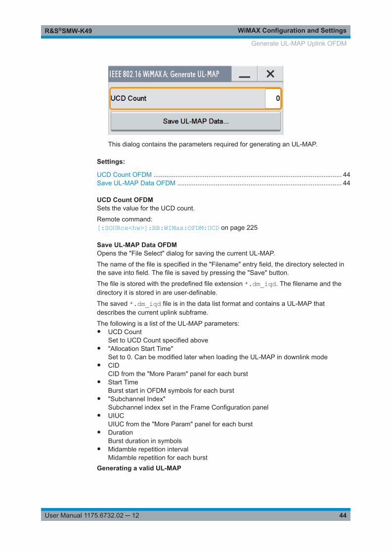
This dialog contains the parameters required for generating an UL-MAP.
Settings:
UCD Count OFDM ....................................................................................................... 44Save UL-MAP Data OFDM .......................................................................................... 44
UCD Count OFDMSets the value for the UCD count.
Remote command: [:SOURce<hw>]:BB:WIMax:OFDM:UCD on page 225
Save UL-MAP Data OFDMOpens the "File Select" dialog for saving the current UL-MAP.
The name of the file is specified in the "Filename" entry field, the directory selected inthe save into field. The file is saved by pressing the "Save" button.
The file is stored with the predefined file extension *.dm_iqd. The filename and thedirectory it is stored in are user-definable.
The saved *.dm_iqd file is in the data list format and contains a UL-MAP thatdescribes the current uplink subframe.
The following is a list of the UL-MAP parameters:● UCD Count
Set to UCD Count specified above● "Allocation Start Time"
Set to 0. Can be modified later when loading the UL-MAP in downlink mode● CID
CID from the "More Param" panel for each burst● Start Time
Burst start in OFDM symbols for each burst● "Subchannel Index"
Subchannel index set in the Frame Configuration panel● UIUC
UIUC from the "More Param" panel for each burst● Duration
Burst duration in symbols● Midamble repetition interval
Midamble repetition for each burstGenerating a valid UL-MAP
Generate UL-MAP Uplink OFDM
WiMAX Configuration and SettingsR&S®SMW-K49
45User Manual 1175.6732.02 ─ 12
The following steps are required to generate a valid UL-MAP● Switch to uplink mode● Define the layout of the uplink subframe by setting a number of bursts and specify-
ing the parameters above for each burst● Select "Generate UL-MAP" and save the UL-MAP to a file● Switch to downlink mode● Set one downlink burst to "Burst Type UL-MAP"● Open the "More Params" panel● Select "UL-MAP File" and load the file created before.The downlink frame is then transmitting a UL-MAP that specifies the uplink structuredefined in uplink mode before.
Remote command: [:SOURce<hw>]:BB:WIMax:OFDM:ULMap:CREate on page 225
4.10 DL-MAP Configuration Downlink OFDM
Access:
1. Select "General > Physical Layer Mode > OFDM".
2. Select "Link Direction > Downlink".
3. Select "Frame Configuration (OFDM) > Frame Configuration > Burst Table".
4. Select "Burst Type > DL-MAP".
5. Select "More Parameter > Configure".
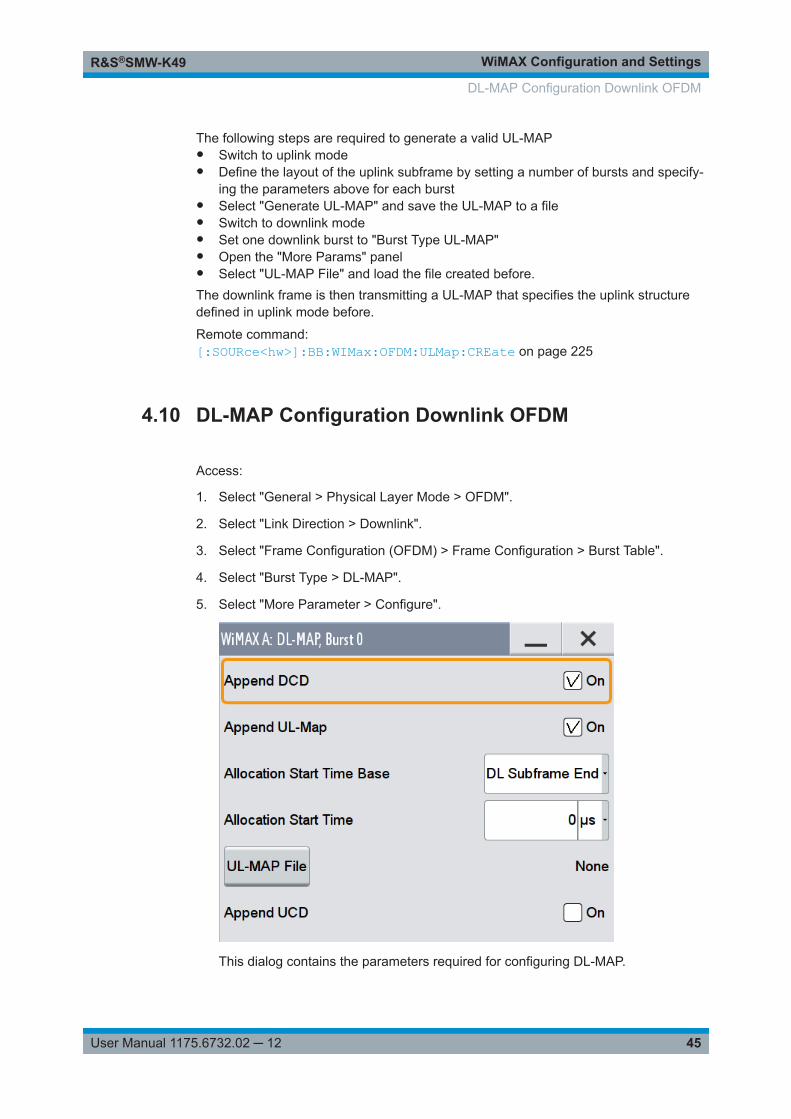
This dialog contains the parameters required for configuring DL-MAP.
DL-MAP Configuration Downlink OFDM
WiMAX Configuration and SettingsR&S®SMW-K49
46User Manual 1175.6732.02 ─ 12
Settings:
Append DCD OFDM .................................................................................................... 46Append UL-Map OFDM ............................................................................................... 46Allocation Start Timebase OFDM .................................................................................46Allocation Start Time OFDM .........................................................................................46UL-MAP File OFDM ..................................................................................................... 46Append UCD OFDM .................................................................................................... 46
Append DCD OFDMIf activated, a DCD is appended to the DL-MAP. The DCD message carries its ownMAC header and CRC, but is included within the DL-MAP burst.
Remote command: [:SOURce<hw>]:BB:WIMax:OFDM:BURSt<ch0>:DLMap:DCD:STATe on page 211
Append UL-Map OFDMIf activated, a UL-Map is appended to the DL-Map.
Remote command: [:SOURce<hw>]:BB:WIMax:OFDM:BURSt<ch0>:DLMap:ULM:STATe on page 212
Allocation Start Timebase OFDMSelects the allocation start timebase, required for the UL-Map appended to the DL-Map. The "Allocation Start Time" field of the UL-Map specifies the start of the uplinksubframe.
If "Start Timebase = DL Subframe End", the "Allocation Start Time" of the UL-Map isset to the end of the downlink subframe+ the value set with the parameter AllocationStart Time OFDM .
When "Start Timebase = Frame Start", the allocation start Time of the UL-Map is set tothe beginning of the frame+ the value set with the parameter Allocation Start TimeOFDM .
Remote command: [:SOURce<hw>]:BB:WIMax:OFDM:BURSt<ch0>:DLMap:AMODe on page 211
Allocation Start Time OFDMSets the "Allocation Start Time" in the UL-Map, appended to the DL-Map.
Remote command: [:SOURce<hw>]:BB:WIMax:OFDM:BURSt<ch0>:DLMap:ATIMe on page 211
UL-MAP File OFDMOpens the dialog for selecting the UL-Map file.
Remote command: n.a.
Append UCD OFDMIf activated, the UCD is appended to the DL-MAP. The UCD message is transmittedwith its own MAC header and CRC, included in the same burst allocation used by theDL-MAP.
DL-MAP Configuration Downlink OFDM
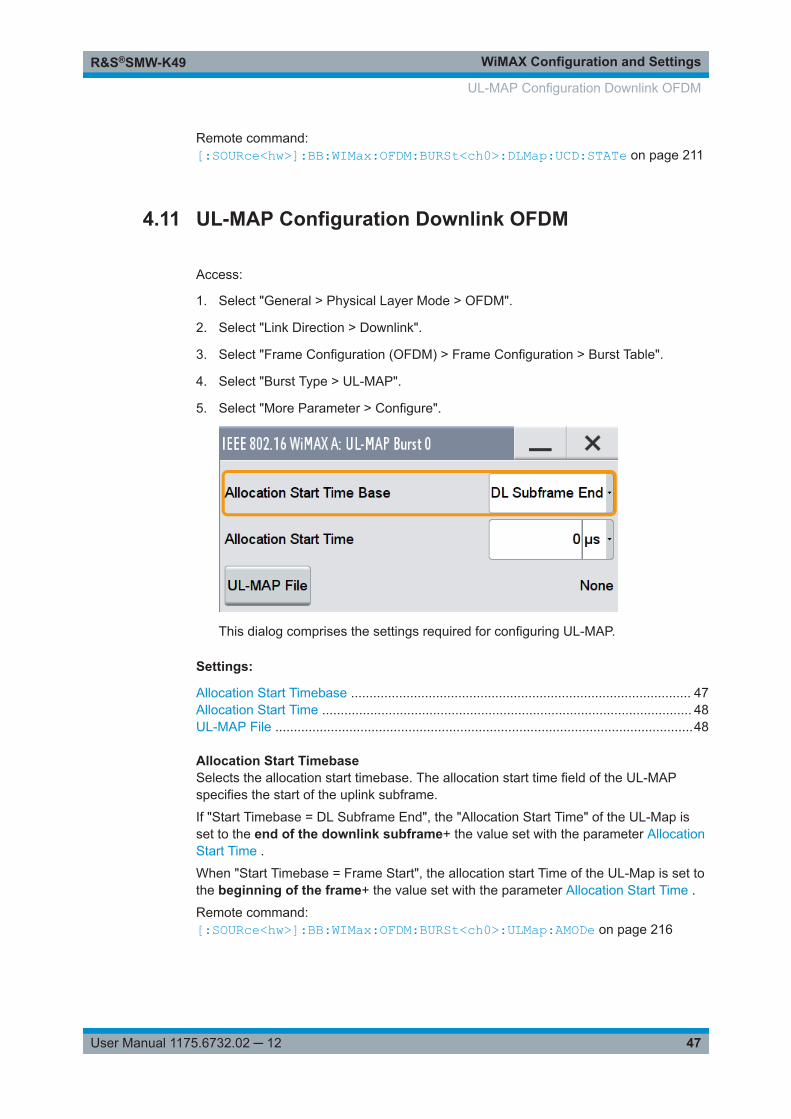
WiMAX Configuration and SettingsR&S®SMW-K49
47User Manual 1175.6732.02 ─ 12
Remote command: [:SOURce<hw>]:BB:WIMax:OFDM:BURSt<ch0>:DLMap:UCD:STATe on page 211
4.11 UL-MAP Configuration Downlink OFDM
Access:
1. Select "General > Physical Layer Mode > OFDM".
2. Select "Link Direction > Downlink".
3. Select "Frame Configuration (OFDM) > Frame Configuration > Burst Table".
4. Select "Burst Type > UL-MAP".
5. Select "More Parameter > Configure".
This dialog comprises the settings required for configuring UL-MAP.
Settings:
Allocation Start Timebase ............................................................................................ 47Allocation Start Time .................................................................................................... 48UL-MAP File .................................................................................................................48
Allocation Start TimebaseSelects the allocation start timebase. The allocation start time field of the UL-MAPspecifies the start of the uplink subframe.
If "Start Timebase = DL Subframe End", the "Allocation Start Time" of the UL-Map isset to the end of the downlink subframe+ the value set with the parameter AllocationStart Time .
When "Start Timebase = Frame Start", the allocation start Time of the UL-Map is set tothe beginning of the frame+ the value set with the parameter Allocation Start Time .
Remote command: [:SOURce<hw>]:BB:WIMax:OFDM:BURSt<ch0>:ULMap:AMODe on page 216
UL-MAP Configuration Downlink OFDM
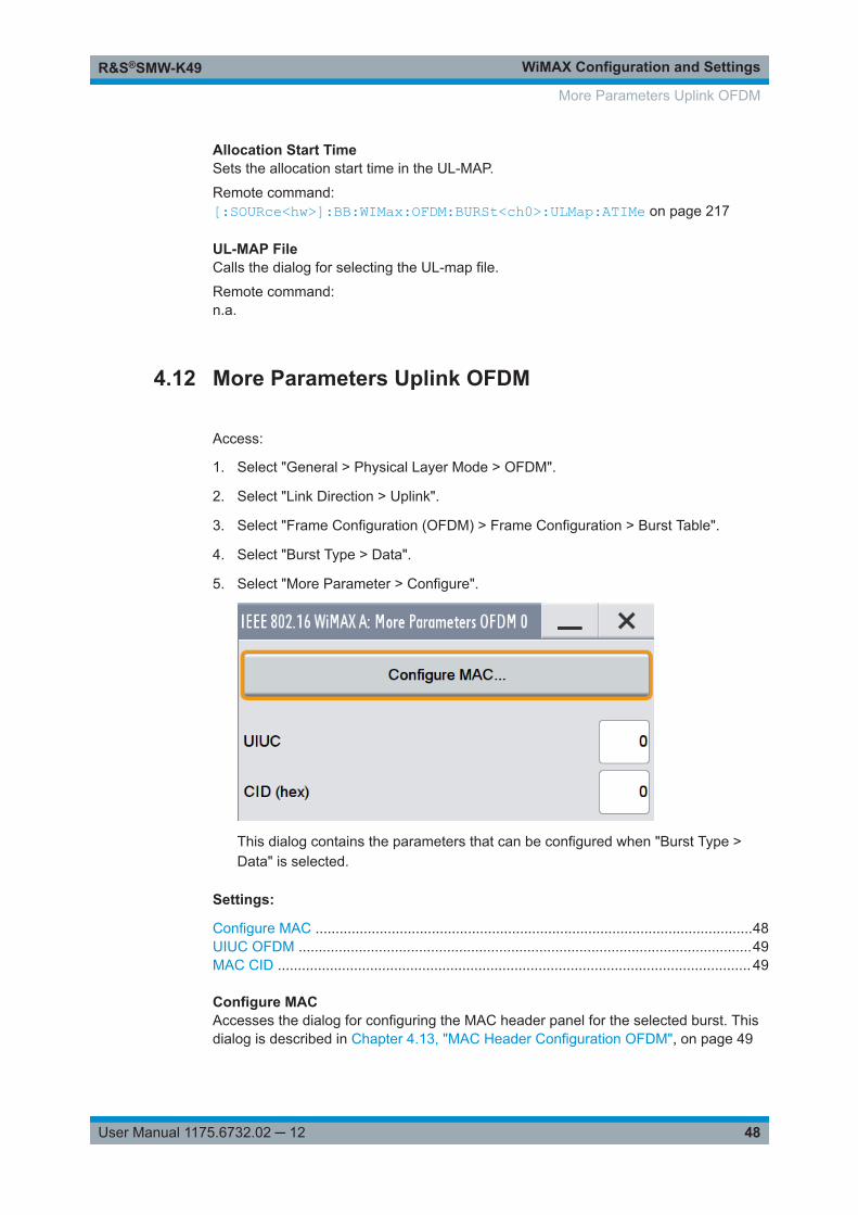
WiMAX Configuration and SettingsR&S®SMW-K49
48User Manual 1175.6732.02 ─ 12
Allocation Start TimeSets the allocation start time in the UL-MAP.
Remote command: [:SOURce<hw>]:BB:WIMax:OFDM:BURSt<ch0>:ULMap:ATIMe on page 217
UL-MAP FileCalls the dialog for selecting the UL-map file.
Remote command: n.a.
4.12 More Parameters Uplink OFDM
Access:
1. Select "General > Physical Layer Mode > OFDM".
2. Select "Link Direction > Uplink".
3. Select "Frame Configuration (OFDM) > Frame Configuration > Burst Table".
4. Select "Burst Type > Data".
5. Select "More Parameter > Configure".
This dialog contains the parameters that can be configured when "Burst Type >Data" is selected.
Settings:
Configure MAC .............................................................................................................48UIUC OFDM .................................................................................................................49MAC CID ...................................................................................................................... 49
Configure MACAccesses the dialog for configuring the MAC header panel for the selected burst. Thisdialog is described in Chapter 4.13, "MAC Header Configuration OFDM", on page 49
More Parameters Uplink OFDM

WiMAX Configuration and SettingsR&S®SMW-K49
49User Manual 1175.6732.02 ─ 12
Remote command: n.a.
UIUC OFDMSets the specific UIUC.
Remote command: [:SOURce<hw>]:BB:WIMax:OFDM:BURSt<ch0>:UIUC on page 216
MAC CIDSets the connection control identifier (CID) of the medium access control layer (MAC).The CID identifies a connection to equivalent peers in the MAC of the base station andsubscriber station.
This parameter is identical to the CID set in the MAC Header settings.
Remote command: [:SOURce<hw>]:BB:WIMax:OFDM:BURSt<ch0>:MAC:CID on page 213
4.13 MAC Header Configuration OFDM
Access:
1. Select "General > Physical Layer Mode > OFDM".
2. Select "Link Direction > Uplink".
3. Select "Frame Configuration (OFDM) > Frame Configuration > Burst Table".
4. Select "Burst Type > Data".
5. Select "More Parameter > Configure > Configure MAC".
MAC Header Configuration OFDM
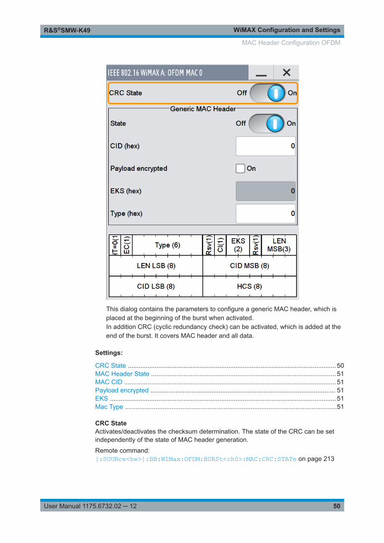
WiMAX Configuration and SettingsR&S®SMW-K49
50User Manual 1175.6732.02 ─ 12
This dialog contains the parameters to configure a generic MAC header, which isplaced at the beginning of the burst when activated.In addition CRC (cyclic redundancy check) can be activated, which is added at theend of the burst. It covers MAC header and all data.
Settings:
CRC State .................................................................................................................... 50MAC Header State ....................................................................................................... 51MAC CID ...................................................................................................................... 51Payload encrypted ....................................................................................................... 51EKS .............................................................................................................................. 51Mac Type ......................................................................................................................51
CRC StateActivates/deactivates the checksum determination. The state of the CRC can be setindependently of the state of MAC header generation.
Remote command: [:SOURce<hw>]:BB:WIMax:OFDM:BURSt<ch0>:MAC:CRC:STATe on page 213
MAC Header Configuration OFDM
WiMAX Configuration and SettingsR&S®SMW-K49
51User Manual 1175.6732.02 ─ 12
MAC Header StateActivates the generation of the generic MAC header.
Remote command: [:SOURce<hw>]:BB:WIMax:OFDM:BURSt<ch0>:MAC:STATe on page 214
MAC CIDSets the connection control identifier (CID) of the medium access control layer (MAC).The CID identifies a connection to equivalent peers in the MAC of the base station andsubscriber station.
This parameter is identical to the CID set in the MAC Header settings.
Remote command: [:SOURce<hw>]:BB:WIMax:OFDM:BURSt<ch0>:MAC:CID on page 213
Payload encryptedActivates/deactivates payload encryption.
If activated, the EC (encryption control) field is set to 1 and the EKS (encryption keysequence) field can be set.
Remote command: [:SOURce<hw>]:BB:WIMax:OFDM:BURSt<ch0>:MAC:ENCRypted:STATeon page 214
EKSSets the EKS (encryption key sequence) value in the MAC header. The payloadencryption itself is not performed by the signal generator.
Remote command: [:SOURce<hw>]:BB:WIMax:OFDM:BURSt<ch0>:MAC:EKS on page 213
Mac TypeSpecifies the MAC type.
The value of the 6-bit type field is set which indicates the payload type, including thepresence of subheaders.
Remote command: [:SOURce<hw>]:BB:WIMax:OFDM:BURSt<ch0>:MAC:TYPE on page 214
4.14 Frame Configuration OFDMA
Access:
1. Select "General > Physical Layer Mode > OFDMA".
2. Select "Frame Configuration (OFDMA) > Frame Configuration".
Frame Configuration OFDMA
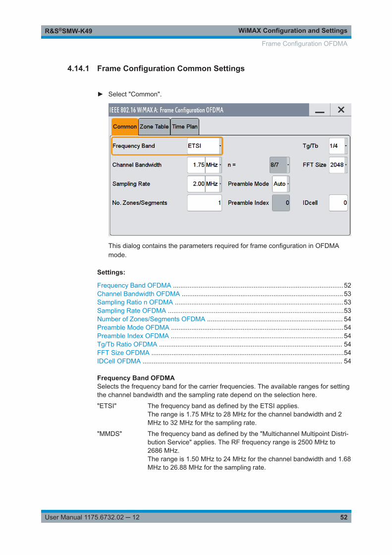
WiMAX Configuration and SettingsR&S®SMW-K49
52User Manual 1175.6732.02 ─ 12
4.14.1 Frame Configuration Common Settings
► Select "Common".
This dialog contains the parameters required for frame configuration in OFDMAmode.
Settings:
Frequency Band OFDMA .............................................................................................52Channel Bandwidth OFDMA ........................................................................................ 53Sampling Ratio n OFDMA ............................................................................................53Sampling Rate OFDMA ................................................................................................53Number of Zones/Segments OFDMA .......................................................................... 54Preamble Mode OFDMA ..............................................................................................54Preamble Index OFDMA .............................................................................................. 54Tg/Tb Ratio OFDMA .................................................................................................... 54FFT Size OFDMA .........................................................................................................54IDCell OFDMA ............................................................................................................. 54
Frequency Band OFDMASelects the frequency band for the carrier frequencies. The available ranges for settingthe channel bandwidth and the sampling rate depend on the selection here.
"ETSI" The frequency band as defined by the ETSI applies.The range is 1.75 MHz to 28 MHz for the channel bandwidth and 2MHz to 32 MHz for the sampling rate.
"MMDS" The frequency band as defined by the "Multichannel Multipoint Distri-bution Service" applies. The RF frequency range is 2500 MHz to2686 MHz.The range is 1.50 MHz to 24 MHz for the channel bandwidth and 1.68MHz to 26.88 MHz for the sampling rate.
Frame Configuration OFDMA
WiMAX Configuration and SettingsR&S®SMW-K49
53User Manual 1175.6732.02 ─ 12
"WCS" The frequency band as defined by the "Wireless Communication Ser-vice" applies. It is in the 2.3 GHz band of the electromagnetic spec-trum from 2305 MHz to 2320 MHz and 2345 MHz to 2360 MHz.The range is 2.5 MHz to 15 MHz for the channel bandwidth and 2.8MHz to 16.8 MHz for the sampling rate.
"U-NII" The frequency band as defined by the "Unlicensed National Informa-tion Infrastructure" applies. It is in the 5 GHz band of the electromag-netic spectrum from 5150 GHz to 5350 GHz and 5750 GHz to 5825GHz.The range is 10 MHz to 20 MHz for the channel bandwidth and 11.2MHz to 22 MHz for the sampling rate.
"WiBro" The frequency band as defined by the Telecommunications Technol-ogy Association of Korea. It is in the 2.3 GHz band of the electromag-netic spectrum.
"User" This mode is provided for choosing any other channel bandwidth /sampling rate combination.The range is 1.25 MHz to 28 MHz for the channel bandwidth and 1.4MHz to 32 MHz for the sampling rate.
Remote command: [:SOURce<hw>]:BB:WIMax:AOFDm:FBANd on page 149
Channel Bandwidth OFDMASets the channel bandwidth. The range is 1.25 MHz to 28 MHz.
The selected channel bandwidth has to be a multiple of 1.25, 1.5, 1.75, 2.0 MHz or2.75 MHz. The channel bandwidth determines the parameter n (see Sampling Ratio nOFDMA ).● For channel bandwidth
– A multiple of 1.75 MHz then n = 8/7– A multiple of 1.5 MHz then n = 28/25– Aa multiple of 1.25 MHz then n = 28/25– A multiple of 2.75 MHz then n = 28/25– A multiple of 2.0 MHz then n = 28/25
● Else for channel bandwidth not otherwise specified then n = 8/7The sampling rate is derived from the channel bandwidth as follows:
SamplingRate = floor (n * ChannelBandwidth / 8000) * 8000
Remote command: [:SOURce<hw>]:BB:WIMax:AOFDm:BW on page 148
Sampling Ratio n OFDMAIndicates the sampling ratio. The sampling ratio is determined by the channel band-width (see Channel Bandwidth OFDMA ).
Remote command: [:SOURce<hw>]:BB:WIMax:AOFDm:N? on page 151
Sampling Rate OFDMASets the sampling rate. The possible settings depend on the selected frequency band.The full range in User mode is 1.44 MHz to 32 MHz.
Frame Configuration OFDMA
WiMAX Configuration and SettingsR&S®SMW-K49
54User Manual 1175.6732.02 ─ 12
The sampling rate is related to the channel bandwidth by the parameter n:
SamplingRate = floor (n * ChannelBandwidth / 8000) * 8000
Remote command: [:SOURce<hw>]:BB:WIMax:AOFDm:SRATe on page 152
Number of Zones/Segments OFDMASets the number of active zones/segments in one frame.
Remote command: [:SOURce<hw>]:BB:WIMax:AOFDm:ZONE:COUNt on page 153
Preamble Mode OFDMASelects the mode for selecting the preamble index.
"Auto" The preamble index value is automatically derived from the segmentsused in the first zone and the cell ID parameter. The "PreambleIndex" field below shows the used preamble index. If more than onesegment is active in the first zone, the preamble index shows -1. Inthis case, a multi-segment preamble is generated.
"User" Sets the preamble index to one of the available indices from 1 to 113specified in the "Preamble Index" field.
Remote command: [:SOURce<hw>]:BB:WIMax:AOFDm:PREamble:INDex:MODE on page 152
Preamble Index OFDMASets the preamble index to one of the available indices from 1 to 113 in preamblemode "user".
Remote command: [:SOURce<hw>]:BB:WIMax:AOFDm:PREamble:INDex on page 152
Tg/Tb Ratio OFDMASelects the ratio of guard period to symbol period.
This value sets the length of the cyclic prefix in fractions of the symbol period.
Remote command: [:SOURce<hw>]:BB:WIMax:AOFDm:TGTB on page 153
FFT Size OFDMASelects the FFT size.
Remote command: [:SOURce<hw>]:BB:WIMax:AOFDm:FFT on page 149
IDCell OFDMASets the cell ID. The value is used in the preamble and for the permutation equationsin the first downlink zone. It partly sets the subcarrier randomizer initialization vector inthe first downlink zone.
Remote command: [:SOURce<hw>]:BB:WIMax:AOFDm:IDCell on page 150
Frame Configuration OFDMA
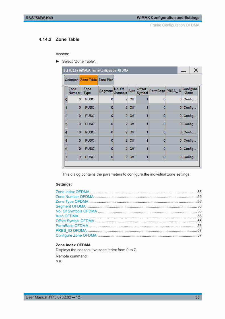
WiMAX Configuration and SettingsR&S®SMW-K49
55User Manual 1175.6732.02 ─ 12
4.14.2 Zone Table
Access:
► Select "Zone Table".
This dialog contains the parameters to configure the individual zone settings.
Settings:
Zone Index OFDMA ..................................................................................................... 55Zone Number OFDMA ................................................................................................. 56Zone Type OFDMA ...................................................................................................... 56Segment OFDMA .........................................................................................................56No. Of Symbols OFDMA .............................................................................................. 56Auto OFDMA ................................................................................................................56Offset Symbol OFDMA .................................................................................................56PermBase OFDMA ...................................................................................................... 56PRBS_ID OFDMA ........................................................................................................57Configure Zone OFDMA .............................................................................................. 57
Zone Index OFDMADisplays the consecutive zone index from 0 to 7.
Remote command: n.a.
Frame Configuration OFDMA
WiMAX Configuration and SettingsR&S®SMW-K49
56User Manual 1175.6732.02 ─ 12
Zone Number OFDMASets the zone number of the zone. The value range is 0 to 7. Zones are generated inthe order of zone number, the lowest zone number is generated first. If the same zonenumber is applied to more than one row, different segments can be used within onezone. In this case, the segment numbers must differ and the activated subchannels ofthe segments must not overlap.
Remote command: [:SOURce<hw>]:BB:WIMax:AOFDm:ZONE<st0>:NUMBer on page 156
Zone Type OFDMASelects the type of subcarrier permutation for the zone.
Remote command: [:SOURce<hw>]:BB:WIMax:AOFDm[:ZONE<st0>]:TYPE on page 206
Segment OFDMASelects the segment of the zone index. Multiple segments within one zone can be con-figured by setting the same zone number and configuring different segment numbersfor each zone index. The activated subchannels must not overlap between the seg-ments of one zone.
Remote command: [:SOURce<hw>]:BB:WIMax:AOFDm:ZONE<st0>:SEGMent on page 158
No. Of Symbols OFDMASets the zone length in number of symbols. Zones with identical zone number have thesame length, as they overlap in time.
Remote command: [:SOURce<hw>]:BB:WIMax:AOFDm:ZONE<st0>:SYMBol:COUNt on page 166
Auto OFDMAActivates or deactivates automatic zone length. The number of symbols in the zone isderived from the configured bursts such that all bursts fit into the zone, except if theframe duration is exceeded.
Remote command: [:SOURce<hw>]:BB:WIMax:AOFDm:ZONE<st0>:SYMBol:COUNt:AUTOon page 167
Offset Symbol OFDMADisplays the symbol offset of the zone.
Remote command: [:SOURce<hw>]:BB:WIMax:AOFDm:ZONE<st0>:SYMBol:OFFSet? on page 167
PermBase OFDMASelects the PermBase of the zone.
Remote command: [:SOURce<hw>]:BB:WIMax:AOFDm:ZONE<st0>:PERMbase on page 157
Frame Configuration OFDMA
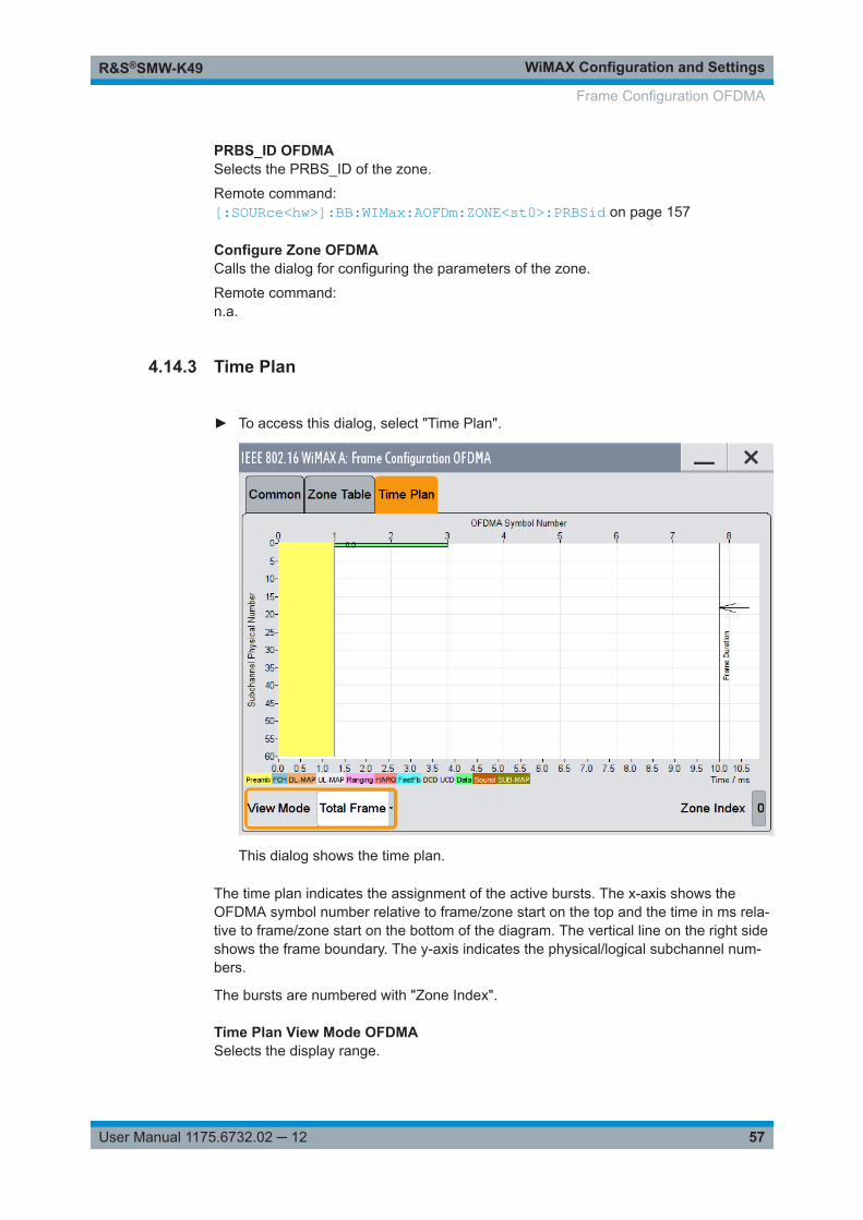
WiMAX Configuration and SettingsR&S®SMW-K49
57User Manual 1175.6732.02 ─ 12
PRBS_ID OFDMASelects the PRBS_ID of the zone.
Remote command: [:SOURce<hw>]:BB:WIMax:AOFDm:ZONE<st0>:PRBSid on page 157
Configure Zone OFDMACalls the dialog for configuring the parameters of the zone.
Remote command: n.a.
4.14.3 Time Plan
► To access this dialog, select "Time Plan".
This dialog shows the time plan.
The time plan indicates the assignment of the active bursts. The x-axis shows theOFDMA symbol number relative to frame/zone start on the top and the time in ms rela-tive to frame/zone start on the bottom of the diagram. The vertical line on the right sideshows the frame boundary. The y-axis indicates the physical/logical subchannel num-bers.
The bursts are numbered with "Zone Index".
Time Plan View Mode OFDMASelects the display range.
Frame Configuration OFDMA
WiMAX Configuration and SettingsR&S®SMW-K49
58User Manual 1175.6732.02 ─ 12
Remote-control command: n.a.
"Total Frame" The display range extends to all zones including the gap to the frameduration. The y-axis shows the physical subchannels. All logical sub-channels are mapped to physical before display. In uplink mode, thedata subchannel rotation is not displayed.
"Subframe" The display range is zoomed to the subframe of the correspondinglink direction.
"Zone" The display range is zoomed to the selected zone index. The y-axisshows the logical subchannels of the zone/segment.
Remote command: n.a.
Time Plan Zone Index OFDMASelects the zone index to be displayed.
This feature is only available, if "Zone" is selected in the "View Mode" field.
Remote command: n.a.
4.15 Zone Configuration OFDMA
Access:
1. Select "General > Physical Layer Mode > OFDMA".
2. Select "Frame Configuration (OFDMA) > Frame Configuration > Zone Table".
3. Select "Configure Zone > Config...".
Content
● OFDMA Common Zone Settings............................................................................ 58● Burst Table.............................................................................................................. 63● Time Plan OFDMA.................................................................................................. 68
4.15.1 OFDMA Common Zone Settings
Access:
► Select "Common".
Zone Configuration OFDMA
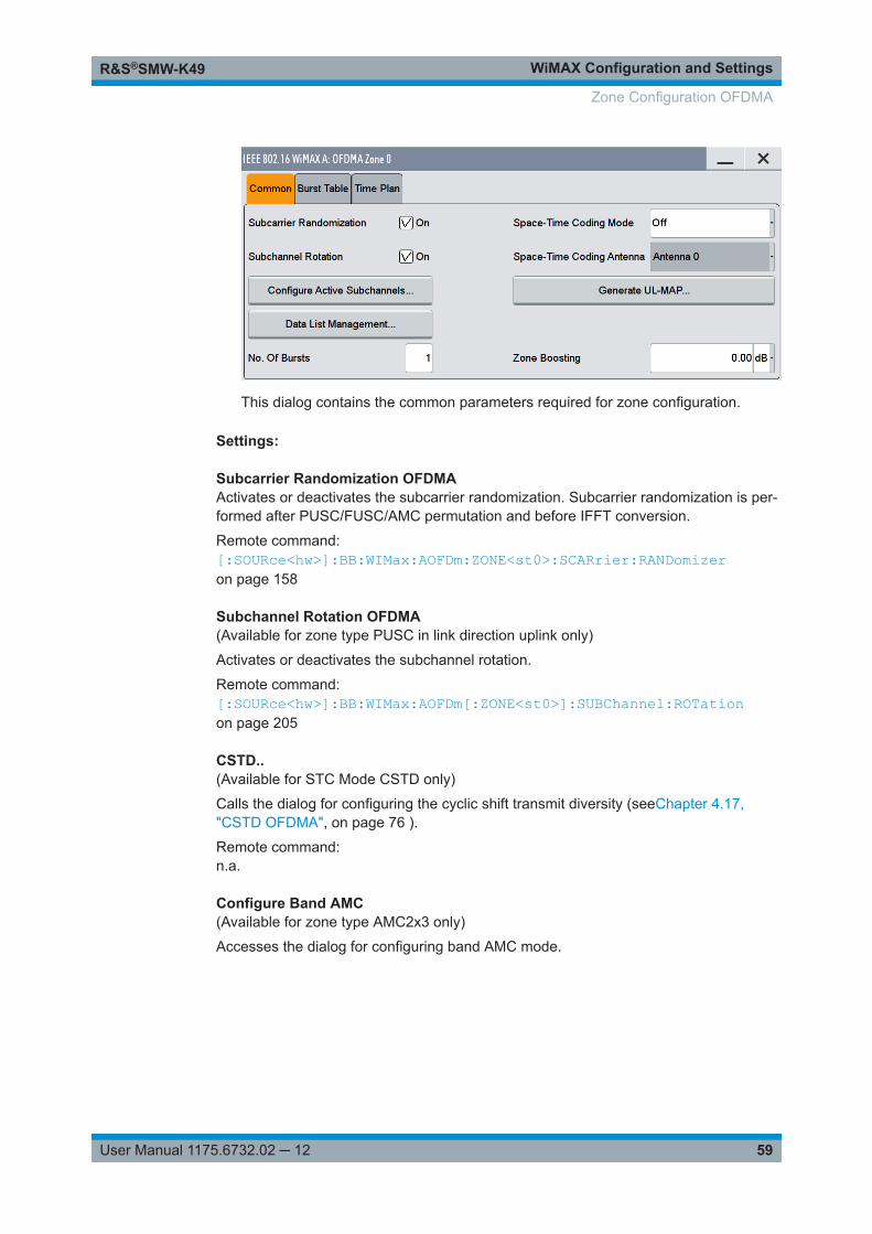
WiMAX Configuration and SettingsR&S®SMW-K49
59User Manual 1175.6732.02 ─ 12
This dialog contains the common parameters required for zone configuration.
Settings:
Subcarrier Randomization OFDMAActivates or deactivates the subcarrier randomization. Subcarrier randomization is per-formed after PUSC/FUSC/AMC permutation and before IFFT conversion.
Remote command: [:SOURce<hw>]:BB:WIMax:AOFDm:ZONE<st0>:SCARrier:RANDomizeron page 158
Subchannel Rotation OFDMA(Available for zone type PUSC in link direction uplink only)
Activates or deactivates the subchannel rotation.
Remote command: [:SOURce<hw>]:BB:WIMax:AOFDm[:ZONE<st0>]:SUBChannel:ROTationon page 205
CSTD..(Available for STC Mode CSTD only)
Calls the dialog for configuring the cyclic shift transmit diversity (seeChapter 4.17,"CSTD OFDMA", on page 76 ).
Remote command: n.a.
Configure Band AMC(Available for zone type AMC2x3 only)
Accesses the dialog for configuring band AMC mode.
Zone Configuration OFDMA
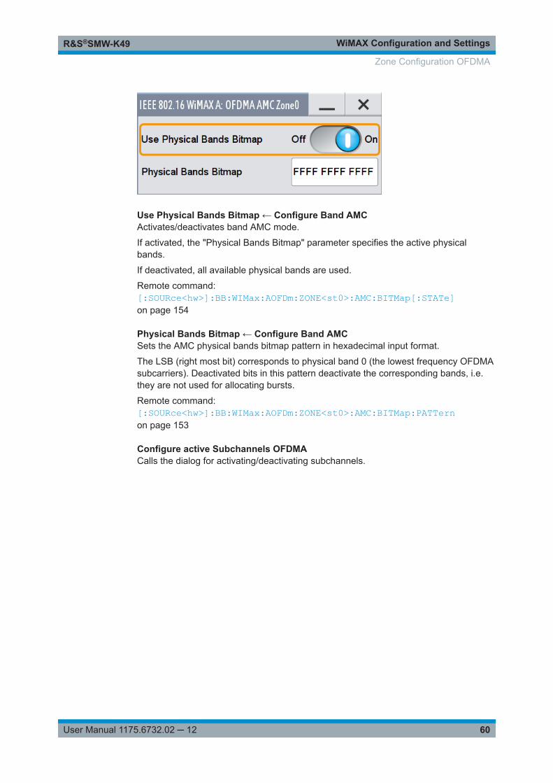
WiMAX Configuration and SettingsR&S®SMW-K49
60User Manual 1175.6732.02 ─ 12
Use Physical Bands Bitmap ← Configure Band AMCActivates/deactivates band AMC mode.
If activated, the "Physical Bands Bitmap" parameter specifies the active physicalbands.
If deactivated, all available physical bands are used.
Remote command: [:SOURce<hw>]:BB:WIMax:AOFDm:ZONE<st0>:AMC:BITMap[:STATe]on page 154
Physical Bands Bitmap ← Configure Band AMCSets the AMC physical bands bitmap pattern in hexadecimal input format.
The LSB (right most bit) corresponds to physical band 0 (the lowest frequency OFDMAsubcarriers). Deactivated bits in this pattern deactivate the corresponding bands, i.e.they are not used for allocating bursts.
Remote command: [:SOURce<hw>]:BB:WIMax:AOFDm:ZONE<st0>:AMC:BITMap:PATTernon page 153
Configure active Subchannels OFDMACalls the dialog for activating/deactivating subchannels.
Zone Configuration OFDMA
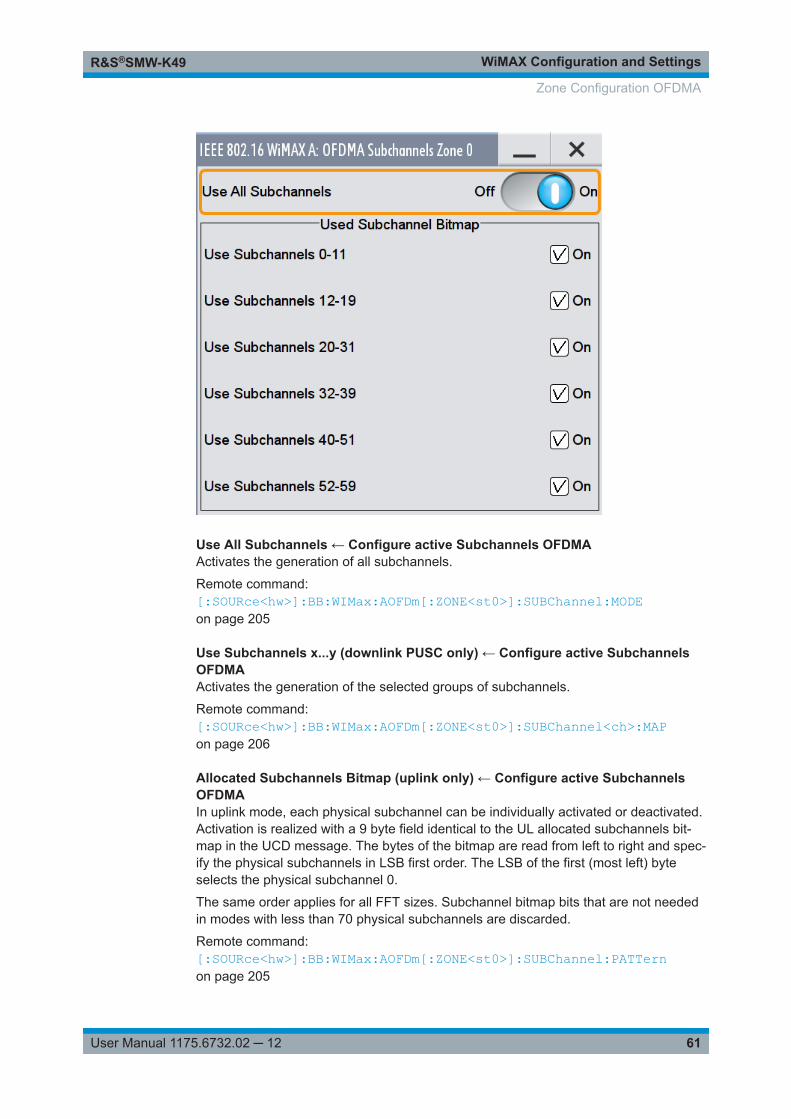
WiMAX Configuration and SettingsR&S®SMW-K49
61User Manual 1175.6732.02 ─ 12
Use All Subchannels ← Configure active Subchannels OFDMAActivates the generation of all subchannels.
Remote command: [:SOURce<hw>]:BB:WIMax:AOFDm[:ZONE<st0>]:SUBChannel:MODEon page 205
Use Subchannels x...y (downlink PUSC only) ← Configure active SubchannelsOFDMAActivates the generation of the selected groups of subchannels.
Remote command: [:SOURce<hw>]:BB:WIMax:AOFDm[:ZONE<st0>]:SUBChannel<ch>:MAPon page 206
Allocated Subchannels Bitmap (uplink only) ← Configure active SubchannelsOFDMAIn uplink mode, each physical subchannel can be individually activated or deactivated.Activation is realized with a 9 byte field identical to the UL allocated subchannels bit-map in the UCD message. The bytes of the bitmap are read from left to right and spec-ify the physical subchannels in LSB first order. The LSB of the first (most left) byteselects the physical subchannel 0.
The same order applies for all FFT sizes. Subchannel bitmap bits that are not neededin modes with less than 70 physical subchannels are discarded.
Remote command: [:SOURce<hw>]:BB:WIMax:AOFDm[:ZONE<st0>]:SUBChannel:PATTernon page 205
Zone Configuration OFDMA
WiMAX Configuration and SettingsR&S®SMW-K49
62User Manual 1175.6732.02 ─ 12
No of Bursts OFDMASets the number of active bursts in the zone/segment.
Remote command: [:SOURce<hw>]:BB:WIMax:AOFDm[:ZONE<st0>]:BURSt[:COUNt] on page 199
Space-Time Coding Mode OFDMASets the space-time coding mode or switches diversity off.
"Off" Deactivates diversity.
"2 Antennas, Matrix A/ 2 Antennas, Matrix B"Sets the space-time coding mode to 2 Antennas and Matrix A orMatrix B encoding respectively.
"4 Antennas, Matrix A/ 4 Antennas, Matrix B/ 4 Antennas, Matrix C"Sets the space-time coding mode to four Antennas with Matrix A,Matrix B or Matrix C encoding respectively.
"Burst Defined" Enables mixing Matrix A and Matrix B encoding on burst level.The used matrix can be defined in the "More Parameter" dialog box ofeach burst.See also Data Configuration OFDMA and UL-MAP ConfigurationDownlink OFDM.
"Collaborative Multiplexing"Enables uplink collaborative spatial multiplexing.
"CSTD" Enables cyclic shift transmit diversity.The CSTD parameters are set in the CSTD dialog (see CSTDOFDMA).
Remote command: [:SOURce<hw>]:BB:WIMax:AOFDm:ZONE<st0>:STC:MODE on page 166
Space-Time Coding Antenna OFDMASets the antenna for the space-time coding modes.
Remote command: [:SOURce<hw>]:BB:WIMax:AOFDm:ZONE<st0>:STC:ANTenna on page 166
Generate UL-MAP(Available for link direction uplink only)
Accesses the dialog for generating a UL-MAP.
Remote command: n.a.
Dedicated Pilots OFDMA(This feature is available only for zone type AMC and PUSC with link direction Down-link).
When activated, pilot symbols are generated for subchannels with allocated burstsonly. When deactivated, pilot symbols are generated for all subchannels allocated tothe current segment, whether bursts are active on these subchannels.
Remote command: [:SOURce<hw>]:BB:WIMax:AOFDm:ZONE<st0>:PILDedicated on page 157
Zone Configuration OFDMA
WiMAX Configuration and SettingsR&S®SMW-K49
63User Manual 1175.6732.02 ─ 12
Data List Management…Opens the "Data List Management" dialog. This dialog is used to create and edit a datalist.
All data lists are stored as files with the predefined file extension *.dm_iqd. The file-name and the directory they are stored in are user-definable.
The data lists must be selected as a data source from the subdialogs under the individ-ual function, e.g. in the channel table of the cells.
Note: All data lists are generated and edited by means of the SOURce:BB:DM subsys-tem commands. Files containing data lists usually end with *.dm_iqd. The data lists areselected as a data source for a specific function in the individual subsystems of the dig-ital standard.
Example: Creating and editing the data listSOUR:BB:DM:DLIS:SEL "d_list1"SOUR:BB:DM:DLIS:DATA #B1111010101000001111....SOUR:BB:DM:DLIS:DATA:APP #B1111010101000001111....
Remote command: [:SOURce<hw>]:BB:WIMax:AOFDm[:ZONE<st0>]:BURSt<ch0>:DATAon page 169[:SOURce<hw>]:BB:WIMax:AOFDm[:ZONE<st0>]:BURSt<ch0>:DATA:DSELecton page 170[:SOURce<hw>]:BB:WIMax:OFDM:BURSt<ch0>:DATA on page 209[:SOURce<hw>]:BB:WIMax:OFDM:BURSt<ch0>:DATA:DSELect on page 209[:SOURce<hw>]:BB:WIMax:OFDM:FCH:DATA on page 218[:SOURce<hw>]:BB:WIMax:OFDM:FCH:DATA:DSELect on page 219
Pilot Pattern OFDMASets the pilot pattern in uplink collaborative multiplexing mode.
Remote command: [:SOURce<hw>]:BB:WIMax:AOFDm:ZONE<st0>:STC:PILotpatternon page 166
Zone Boosting OFDMASets an additional zone boosting in dB.
The zone boosting is applied to both the data and pilot carriers.
Remote command: [:SOURce<hw>]:BB:WIMax:AOFDm:ZONE<st0>:BOOSt on page 154
4.15.2 Burst Table
Access:
► Select "Burst Table".
Zone Configuration OFDMA
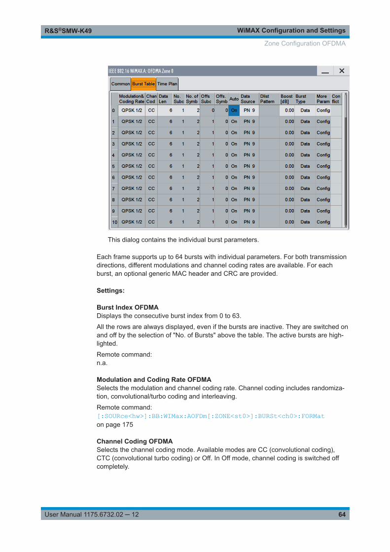
WiMAX Configuration and SettingsR&S®SMW-K49
64User Manual 1175.6732.02 ─ 12
This dialog contains the individual burst parameters.
Each frame supports up to 64 bursts with individual parameters. For both transmissiondirections, different modulations and channel coding rates are available. For eachburst, an optional generic MAC header and CRC are provided.
Settings:
Burst Index OFDMADisplays the consecutive burst index from 0 to 63.
All the rows are always displayed, even if the bursts are inactive. They are switched onand off by the selection of "No. of Bursts" above the table. The active bursts are high-lighted.
Remote command: n.a.
Modulation and Coding Rate OFDMASelects the modulation and channel coding rate. Channel coding includes randomiza-tion, convolutional/turbo coding and interleaving.
Remote command: [:SOURce<hw>]:BB:WIMax:AOFDm[:ZONE<st0>]:BURSt<ch0>:FORMaton page 175
Channel Coding OFDMASelects the channel coding mode. Available modes are CC (convolutional coding),CTC (convolutional turbo coding) or Off. In Off mode, channel coding is switched offcompletely.
Zone Configuration OFDMA
WiMAX Configuration and SettingsR&S®SMW-K49
65User Manual 1175.6732.02 ─ 12
Remote command: [:SOURce<hw>]:BB:WIMax:AOFDm[:ZONE<st0>]:BURSt<ch0>:CCODing:MODEon page 168
Data Length OFDMADetermines the data length in bytes.
The given number of bytes is read from the data source. The total number of databytes in the burst (before channel coding) is determined as follows:
TotalDataBytes = DataLength + MACHeaderBytes + CRCBytes
Additionally, padding with 0xFF bytes is applied at the end of the data sequence to fillup the allocated slots. The allocated slots are specified by "No. of Subch" and "No. ofSymb" in downlink mode and by the "Duration [Slots]" in uplink mode. Thus, the "DataLength" can be lower than the burst's allocated number of bytes.
Up to 10 000 data bytes can be set for each burst.
Remote command: [:SOURce<hw>]:BB:WIMax:AOFDm[:ZONE<st0>]:BURSt<ch0>:DATA:LENGthon page 171
Number of Subchannels OFDMAEnters the number of subchannels for the selected burst.
If the number of subchannels is changed, the data length is adjusted to fill the allocatedspace with data so that no padding has to be applied. The allocated space is definedby "No. of Subch" and "No. of Symb".
The data length can be lowered afterwards if data bytes less than the allocated numberare read from the data source.
Remote command: [:SOURce<hw>]:BB:WIMax:AOFDm[:ZONE<st0>]:BURSt<ch0>:SUBChannel[:COUNt] on page 194
Number of Symbols OFDMAEnters the number of symbols for the selected burst.
If the number of subchannels is changed, the data length is adjusted to fill the allocatedspace with data so that no padding has to be applied. The allocated space is definedby "No. of Subch" and "No. of Symb".
The data length can be decreased afterwards if data bytes less than the allocatednumber are read from the data source. The entered number of symbols is automati-cally adjusted to a multiple of the number of symbols per slot for the set subcarrier per-mutation.
Remote command: [:SOURce<hw>]:BB:WIMax:AOFDm[:ZONE<st0>]:BURSt<ch0>:SYMBol[:COUNt] on page 194
Duration-Slots OFDMAEnters the number of slots for the selected burst. If the number of slots is changed, thedata length is adjusted to fill the specified number of slots with data so that no paddinghas to be applied.
Zone Configuration OFDMA
WiMAX Configuration and SettingsR&S®SMW-K49
66User Manual 1175.6732.02 ─ 12
Remote command: [:SOURce<hw>]:BB:WIMax:AOFDm[:ZONE<st0>]:BURSt<ch0>:SLOT:COUNton page 193
Offset Subchannel OFDMAIndicates the subchannel offset for the selected burst. This value can be modified after"Auto Offset" is deactivated.
It is possible that bursts overlap in manual offset mode. The "Conflict" column indicatesoverlapping bursts.
Remote command: [:SOURce<hw>]:BB:WIMax:AOFDm[:ZONE<st0>]:BURSt<ch0>:OFFSet:SUBChannel on page 186
Offset Symbol OFDMAIndicates the symbol offset for the selected burst. The symbol offset is specified rela-tive to zone start. In the first downlink zone, symbol offset 0 refers to the first symbolafter the preamble.
This value can be modified after "Auto Offset" is deactivated.
The set symbol offset is rounded to a multiple of the number of symbols per slotdefined by the set subcarrier permutation.
It is possible that bursts overlap in manual offset mode. The "Conflict" column indicatesoverlapping bursts.
Remote command: [:SOURce<hw>]:BB:WIMax:AOFDm[:ZONE<st0>]:BURSt<ch0>:OFFSet:SYMBol on page 186
Auto OFDMAActivates/deactivates the "Auto Offset" mode. In auto mode, "Offset Subchannel" and"Offset Symbol" are set such that bursts are not overlapping in the subchannel/symbolspace.
Remote command: [:SOURce<hw>]:BB:WIMax:AOFDm[:ZONE<st0>]:BURSt<ch0>:OFFSet:MODEon page 185
Data Source OFDMASelects data source for the selected bursts.
The following standard data sources are available:● "All 0, All 1"
An internally generated sequence containing 0 data or 1 data.● "PNxx"
An internally generated pseudo-random noise sequence.● "Pattern"
An internally generated sequence according to a bit pattern.Use the "Pattern" box to define the bit pattern.
● "Data List/Select DList"A binary data from a data list, internally or externally generated.Select "Select DList" to access the standard "Select List" dialog.
Zone Configuration OFDMA
WiMAX Configuration and SettingsR&S®SMW-K49
67User Manual 1175.6732.02 ─ 12
– Select the "Select Data List > navigate to the list file *.dm_iqd > Select" toselect an existing data list.
– Use the "New" and "Edit" functions to create internally new data list or to editan existing one.
– Use the standard "File Manager" function to transfer external data lists to theinstrument.
See also:● Section "Modulation Data" in the R&S SMW user manual.● Section "File and Data Management" in the R&S SMW user manual.● Section "Data List Editor" in the R&S SMW user manual
Remote command: [:SOURce<hw>]:BB:WIMax:AOFDm[:ZONE<st0>]:BURSt<ch0>:DATAon page 169[:SOURce<hw>]:BB:WIMax:AOFDm[:ZONE<st0>]:BURSt<ch0>:DATA:PATTernon page 171[:SOURce<hw>]:BB:WIMax:AOFDm[:ZONE<st0>]:BURSt<ch0>:DATA:DSELecton page 170
Boost OFDMASets the burst power in dB. This setting affects the data tones only in downlink mode,the pilot power is fixed. In uplink, the setting affects both data and pilot tones.
Remote command: [:SOURce<hw>]:BB:WIMax:AOFDm[:ZONE<st0>]:BURSt<ch0>:POWeron page 192
Burst Type OFDMASelects the burst type from data, FCH, DL-MAP, UL-MAP, Ranging, HARQ, fast feed-back or SUB-MAP.
"DATA" Regular bursts are called "Data" bursts. All data sources are availablefor this type of burst.
"FCH" An FCH is generated at subchannel and symbol offset 0. See FCHConfiguration Downlink OFDMA on the FCH contents.
"DL-MAP" A DL-MAP is generated, considering all active bursts of all zones.SeeDL-MAP Configuration Downlink OFDMA on the DL-MAP con-tents.
"UL-MAP" A UL-MAP is generated using the specified data list, including addi-tional parameters from the "More Param" dialog. See UL-MAP Con-figuration Downlink OFDMA for more information on how to createUL-MAP bursts.
"Ranging" An uplink ranging allocation is configured, which can be used for ini-tial ranging, periodic ranging, or bandwidth request transmissions.See Ranging Uplink OFDMA for more information on how to createranging channels. The burst type Ranging requires a PUSC zone.
"HARQ" A HARQ burst is generated. See HARQ Configuration OFDMA formore information on how to create HARQ bursts.
Zone Configuration OFDMA
WiMAX Configuration and SettingsR&S®SMW-K49
68User Manual 1175.6732.02 ─ 12
"Fast Feedback"A fast feedback burst is generated. See Fast Feedback ConfigurationOFDMA for more information on how to create fast feedback bursts.The burst type fast feedback requires a PUSC zone.
"DCD" A regular data burst containing a DCD message is generated. TheDCD message specifies a downlink burst profile for each DIUC valuethat is being used in the zone configuration.
"UCD" A regular data burst containing a UCD message is generated. TheUCD message specifies an uplink burst profile for each UIUC valuethat is being used in the zone configuration.
"SUB-MAP" A SUB-DL-UL-MAP message is generated.Altogether up to three SUB-DL-UL-MAP messages can be enabledfor all zones.The SUB-DL-UL-MAP message additional parameters can be config-ured in the SUB-DL-UL-MAP Configuration OFDMA dialog reachedfrom the "More Param" panel.For each data, UL-MAP, HARQ, DCD or UCD burst inclusion into oneof the three available "SUB-DL-UL-MAPs" can be activated. In thiscase, the corresponding map carries a DL-MAP IE specifying theposition of the included burst.
Remote command: [:SOURce<hw>]:BB:WIMax:AOFDm[:ZONE<st0>]:BURSt<ch0>:TYPEon page 195
More Parameter OFDMAAccesses the dialog for configuring additional parameters for the bursts.
The dialog depends on the selected burst type.
Remote command: n.a.
Conflict OFDMAIndicates a conflict between the settings of the bursts.
Conflicts can occur if subchannel and symbol offsets are set manually and two or morebursts overlap. Bursts can also overlap with the FCH or DL-MAP. The position of FCHand DL-MAP is fixed and cannot be changed. In uplink mode, a conflict is also indica-ted for bursts that do not fit into the available zone space and are therefore omitted.
Remote command: [:SOURce<hw>]:BB:WIMax:AOFDm[:ZONE<st0>]:BURSt<ch0>:CONFlict[:STATe]? on page 169
4.15.3 Time Plan OFDMA
Access:
► Select "Time Plan".
Zone Configuration OFDMA
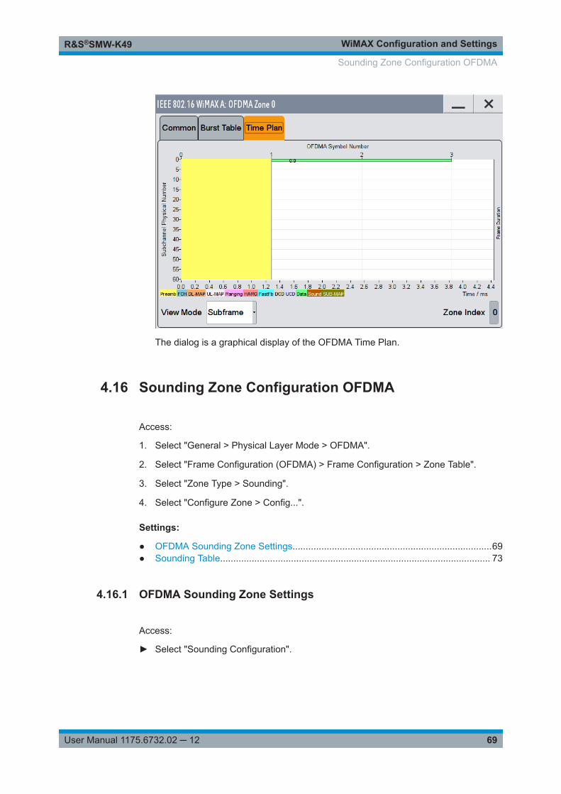
WiMAX Configuration and SettingsR&S®SMW-K49
69User Manual 1175.6732.02 ─ 12
The dialog is a graphical display of the OFDMA Time Plan.
4.16 Sounding Zone Configuration OFDMA
Access:
1. Select "General > Physical Layer Mode > OFDMA".
2. Select "Frame Configuration (OFDMA) > Frame Configuration > Zone Table".
3. Select "Zone Type > Sounding".
4. Select "Configure Zone > Config...".
Settings:
● OFDMA Sounding Zone Settings............................................................................69● Sounding Table....................................................................................................... 73
4.16.1 OFDMA Sounding Zone Settings
Access:
► Select "Sounding Configuration".
Sounding Zone Configuration OFDMA
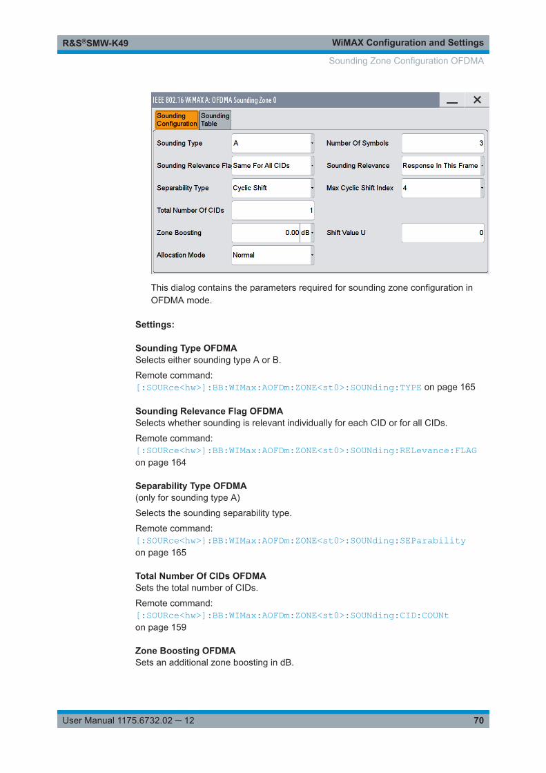
WiMAX Configuration and SettingsR&S®SMW-K49
70User Manual 1175.6732.02 ─ 12
This dialog contains the parameters required for sounding zone configuration inOFDMA mode.
Settings:
Sounding Type OFDMASelects either sounding type A or B.
Remote command: [:SOURce<hw>]:BB:WIMax:AOFDm:ZONE<st0>:SOUNding:TYPE on page 165
Sounding Relevance Flag OFDMASelects whether sounding is relevant individually for each CID or for all CIDs.
Remote command: [:SOURce<hw>]:BB:WIMax:AOFDm:ZONE<st0>:SOUNding:RELevance:FLAGon page 164
Separability Type OFDMA(only for sounding type A)
Selects the sounding separability type.
Remote command: [:SOURce<hw>]:BB:WIMax:AOFDm:ZONE<st0>:SOUNding:SEParabilityon page 165
Total Number Of CIDs OFDMASets the total number of CIDs.
Remote command: [:SOURce<hw>]:BB:WIMax:AOFDm:ZONE<st0>:SOUNding:CID:COUNton page 159
Zone Boosting OFDMASets an additional zone boosting in dB.
Sounding Zone Configuration OFDMA
WiMAX Configuration and SettingsR&S®SMW-K49
71User Manual 1175.6732.02 ─ 12
The zone boosting is applied to both the data and pilot carriers.
Remote command: [:SOURce<hw>]:BB:WIMax:AOFDm:ZONE<st0>:BOOSt on page 154
Allocation Mode OFDMA(only for sounding type A)
Selects the frequency allocation mode for sounding CIDs.
"Normal" The used sounding allocations are specified with "Number Of Freq.Bands" and "Start Freq. Band".
"Band AMC" A "Band Bitmap" pattern determines the frequencies to be sent.
Remote command: [:SOURce<hw>]:BB:WIMax:AOFDm:ZONE<st0>:SOUNding:AMODe on page 158
No. Of Symbols OFDMASets the zone length in number of symbols. Zones with identical zone number have thesame length, as they overlap in time.
Remote command: [:SOURce<hw>]:BB:WIMax:AOFDm:ZONE<st0>:SYMBol:COUNt on page 166
Sounding Relevance OFDMA(only if sounding relevance flag is set to "Same For All CIDs")
Selects the sounding relevance mode.
Remote command: [:SOURce<hw>]:BB:WIMax:AOFDm:ZONE<st0>:SOUNding:RELevance:MODEon page 164
Max Cyclic Shift Index OFDMA(only for sounding type A and separability type cyclic shift)
Sets the value for the maximum cyclic shift index.
Remote command: [:SOURce<hw>]:BB:WIMax:AOFDm:ZONE<st0>:SOUNding:CMAXimumon page 163
Permutation OFDMA(only for sounding type B)
Indicates the permutation used for this sounding zone.
Remote command: [:SOURce<hw>]:BB:WIMax:AOFDm:ZONE<st0>:SOUNding:PERMutation?on page 164
DL PermBase OFDMA(only for sounding type B)
Sets the value for the "DL Perm Base".
Sounding Zone Configuration OFDMA
WiMAX Configuration and SettingsR&S®SMW-K49
72User Manual 1175.6732.02 ─ 12
Remote command: [:SOURce<hw>]:BB:WIMax:AOFDm:ZONE<st0>:SOUNding:DLPermbaseon page 164
Decimation Value OFDMA(only for sounding type A and separability Type decimated subcarriers)
Sets the value for the decimation.
Remote command: [:SOURce<hw>]:BB:WIMax:AOFDm:ZONE<st0>:SOUNding:DECimation:VALueon page 163
Decimation Offset Randomization OFDMA(only for sounding type A and separability type decimated subcarriers)
Activates/deactivates the decimation offset randomization.
Remote command: [:SOURce<hw>]:BB:WIMax:AOFDm:ZONE<st0>:SOUNding:DECimation:RANDomization[:STATe] on page 163
Shift Value U OFDMA(only for sounding type A)
Sets the shift value (u) used for decimation offset and cyclic shift index.
Remote command: [:SOURce<hw>]:BB:WIMax:AOFDm:ZONE<st0>:SOUNding:UVAL on page 165
Sounding Zone Configuration OFDMA
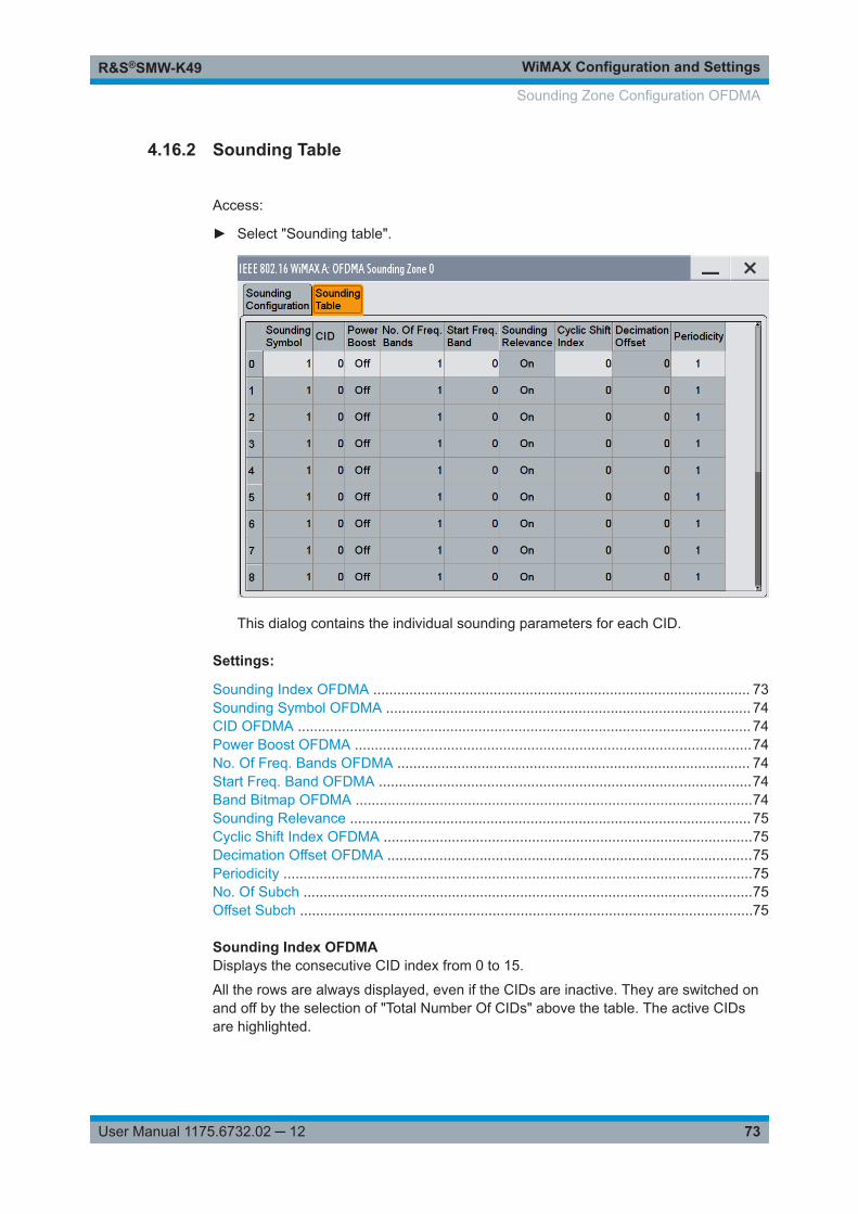
WiMAX Configuration and SettingsR&S®SMW-K49
73User Manual 1175.6732.02 ─ 12
4.16.2 Sounding Table
Access:
► Select "Sounding table".
This dialog contains the individual sounding parameters for each CID.
Settings:
Sounding Index OFDMA .............................................................................................. 73Sounding Symbol OFDMA ........................................................................................... 74CID OFDMA ................................................................................................................. 74Power Boost OFDMA ...................................................................................................74No. Of Freq. Bands OFDMA ........................................................................................ 74Start Freq. Band OFDMA .............................................................................................74Band Bitmap OFDMA ...................................................................................................74Sounding Relevance .................................................................................................... 75Cyclic Shift Index OFDMA ............................................................................................75Decimation Offset OFDMA ...........................................................................................75Periodicity .....................................................................................................................75No. Of Subch ................................................................................................................75Offset Subch .................................................................................................................75
Sounding Index OFDMADisplays the consecutive CID index from 0 to 15.
All the rows are always displayed, even if the CIDs are inactive. They are switched onand off by the selection of "Total Number Of CIDs" above the table. The active CIDsare highlighted.
Sounding Zone Configuration OFDMA
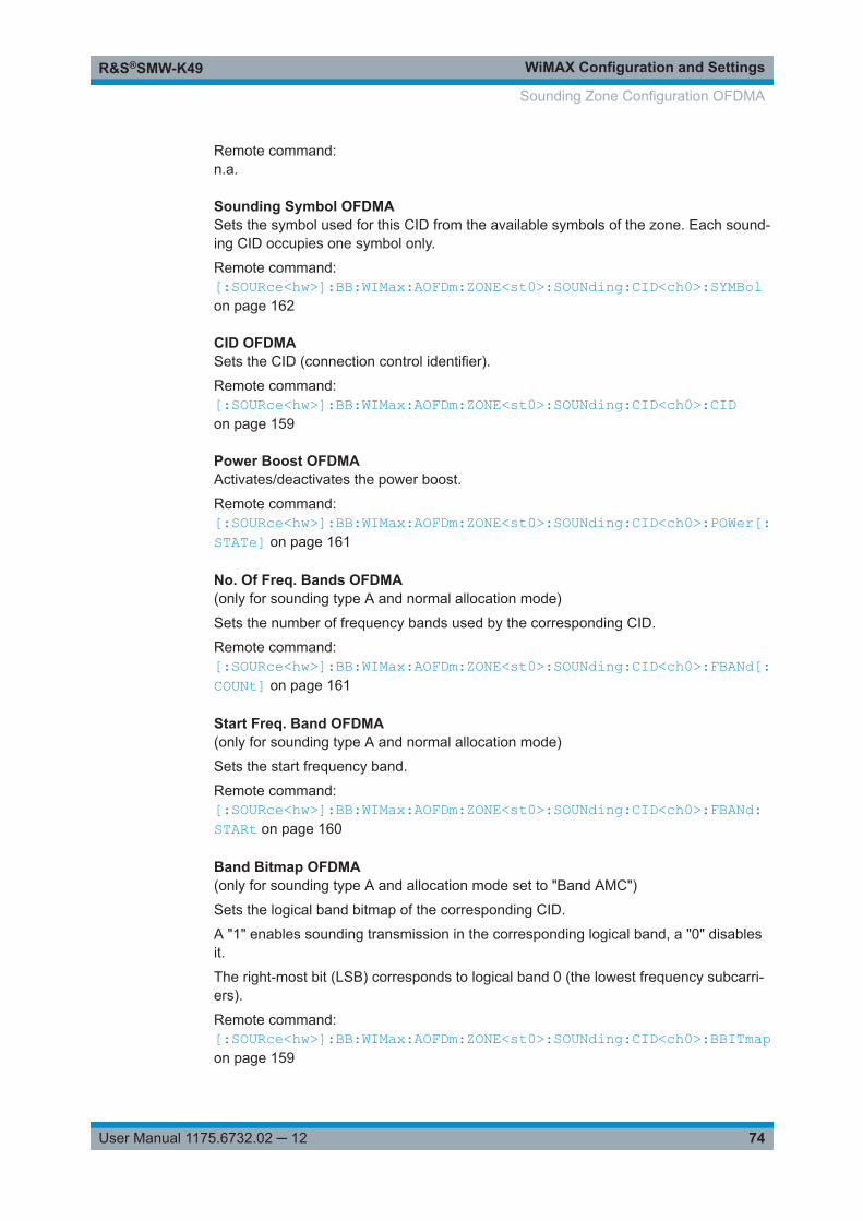
WiMAX Configuration and SettingsR&S®SMW-K49
74User Manual 1175.6732.02 ─ 12
Remote command: n.a.
Sounding Symbol OFDMASets the symbol used for this CID from the available symbols of the zone. Each sound-ing CID occupies one symbol only.
Remote command: [:SOURce<hw>]:BB:WIMax:AOFDm:ZONE<st0>:SOUNding:CID<ch0>:SYMBolon page 162
CID OFDMASets the CID (connection control identifier).
Remote command: [:SOURce<hw>]:BB:WIMax:AOFDm:ZONE<st0>:SOUNding:CID<ch0>:CIDon page 159
Power Boost OFDMAActivates/deactivates the power boost.
Remote command: [:SOURce<hw>]:BB:WIMax:AOFDm:ZONE<st0>:SOUNding:CID<ch0>:POWer[:STATe] on page 161
No. Of Freq. Bands OFDMA(only for sounding type A and normal allocation mode)
Sets the number of frequency bands used by the corresponding CID.
Remote command: [:SOURce<hw>]:BB:WIMax:AOFDm:ZONE<st0>:SOUNding:CID<ch0>:FBANd[:COUNt] on page 161
Start Freq. Band OFDMA(only for sounding type A and normal allocation mode)
Sets the start frequency band.
Remote command: [:SOURce<hw>]:BB:WIMax:AOFDm:ZONE<st0>:SOUNding:CID<ch0>:FBANd:STARt on page 160
Band Bitmap OFDMA(only for sounding type A and allocation mode set to "Band AMC")
Sets the logical band bitmap of the corresponding CID.
A "1" enables sounding transmission in the corresponding logical band, a "0" disablesit.
The right-most bit (LSB) corresponds to logical band 0 (the lowest frequency subcarri-ers).
Remote command: [:SOURce<hw>]:BB:WIMax:AOFDm:ZONE<st0>:SOUNding:CID<ch0>:BBITmapon page 159
Sounding Zone Configuration OFDMA
WiMAX Configuration and SettingsR&S®SMW-K49
75User Manual 1175.6732.02 ─ 12
Sounding RelevanceActivates/deactivates the sounding relevance.
Remote command: [:SOURce<hw>]:BB:WIMax:AOFDm:ZONE<st0>:SOUNding:CID<ch0>:RELevance[:STATe] on page 161
Cyclic Shift Index OFDMA(only for sounding type A)
Sets the value for the cyclic shift index. If the "Separability Type" is set to "DecimatedSubcarriers", the cyclic shift index is not used.
Remote command: [:SOURce<hw>]:BB:WIMax:AOFDm:ZONE<st0>:SOUNding:CID<ch0>:CINDexon page 159
Decimation Offset OFDMA(only for sounding type A)
Sets the value for the decimation offset. If the "Separability Type" is set to "CyclicShift", the decimation offset is not used.
Remote command: [:SOURce<hw>]:BB:WIMax:AOFDm:ZONE<st0>:SOUNding:CID<ch0>:DECoffset on page 160
PeriodicitySets the value for the periodicity.
A value of 0 transmits this sounding CID only once at the beginning of the signalsequence.
A value of 1 activates continuous transmission of the sounding CID with each frame.
Larger values specify the period in frames that active sounding CIDs occur.
Remote command: [:SOURce<hw>]:BB:WIMax:AOFDm:ZONE<st0>:SOUNding:CID<ch0>:PERiodicity on page 161
No. Of Subch(only for sounding type B)
Sets the number of subchannels.
Remote command: [:SOURce<hw>]:BB:WIMax:AOFDm:ZONE<st0>:SOUNding:CID<ch0>:SUBChannel[:COUNt] on page 162
Offset Subch(only for sounding type B)
Sets the subchannel offset.
Remote command: [:SOURce<hw>]:BB:WIMax:AOFDm:ZONE<st0>:SOUNding:CID<ch0>:SUBChannel:OFFSet on page 162
Sounding Zone Configuration OFDMA
WiMAX Configuration and SettingsR&S®SMW-K49
76User Manual 1175.6732.02 ─ 12
4.17 CSTD OFDMA
Access:
1. Select "General > Physical Layer Mode > OFDMA".
2. Select "Link Direction > Downlink".
3. Select "Frame Configuration (OFDMA) > Frame Configuration > Zone Table".
4. Select "Configure Zone > Config...".
5. Select "Common > Space-Time Coding Mode > CSTD".
6. Select "CSTD".
This dialog contains the parameters required to configure the CSTD options inOFDMA mode.
A zone with activated CSTD is encoded like a regular SISO zone (STC off). After, theIFFT a multi-tap delay line is applied to the time-domain signal. Each tap can be weigh-ted with a different linear factor before summation of all taps. The cyclic prefix isapplied on the sum output. Different cyclic-delay filters can be applied to everyantenna.
CSTD OFDMA
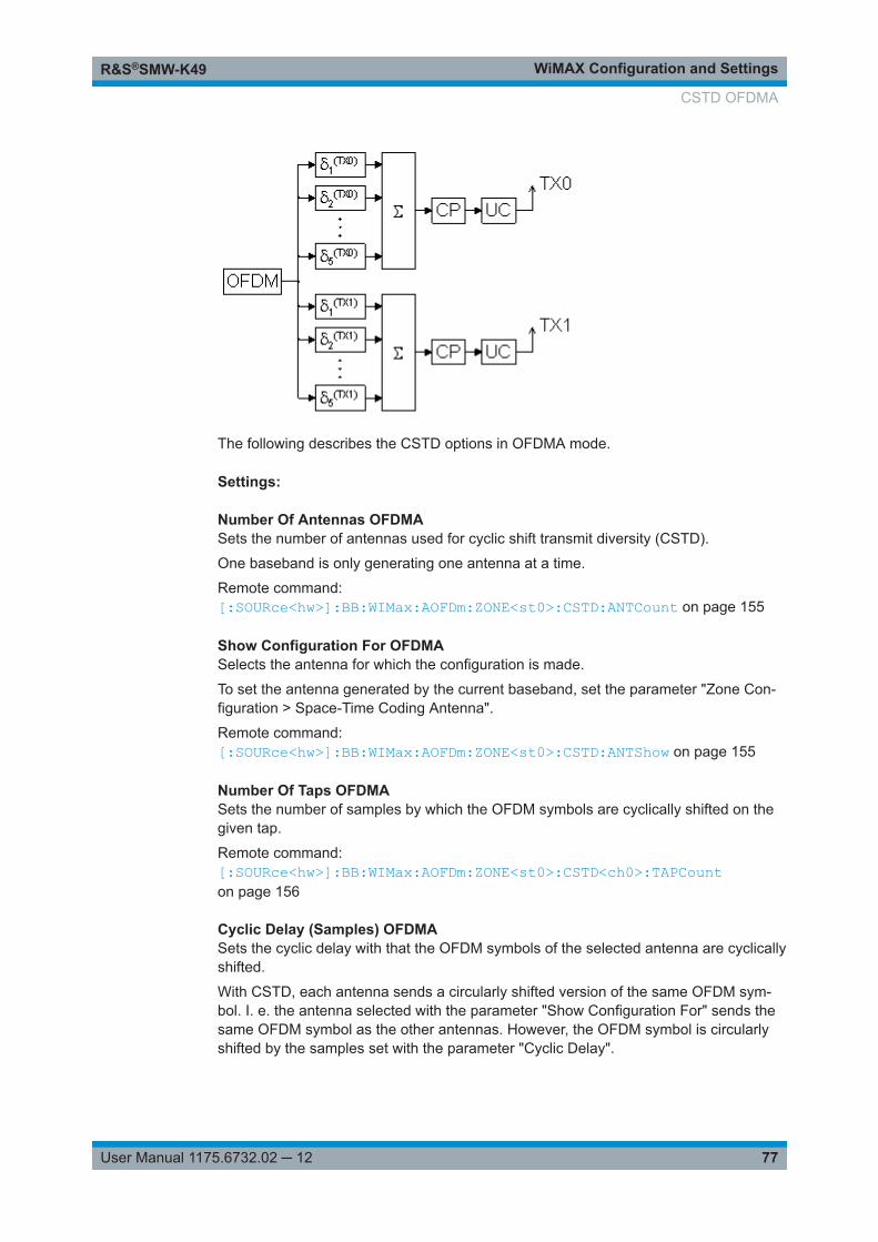
WiMAX Configuration and SettingsR&S®SMW-K49
77User Manual 1175.6732.02 ─ 12
The following describes the CSTD options in OFDMA mode.
Settings:
Number Of Antennas OFDMASets the number of antennas used for cyclic shift transmit diversity (CSTD).
One baseband is only generating one antenna at a time.
Remote command: [:SOURce<hw>]:BB:WIMax:AOFDm:ZONE<st0>:CSTD:ANTCount on page 155
Show Configuration For OFDMASelects the antenna for which the configuration is made.
To set the antenna generated by the current baseband, set the parameter "Zone Con-figuration > Space-Time Coding Antenna".
Remote command: [:SOURce<hw>]:BB:WIMax:AOFDm:ZONE<st0>:CSTD:ANTShow on page 155
Number Of Taps OFDMASets the number of samples by which the OFDM symbols are cyclically shifted on thegiven tap.
Remote command: [:SOURce<hw>]:BB:WIMax:AOFDm:ZONE<st0>:CSTD<ch0>:TAPCounton page 156
Cyclic Delay (Samples) OFDMASets the cyclic delay with that the OFDM symbols of the selected antenna are cyclicallyshifted.
With CSTD, each antenna sends a circularly shifted version of the same OFDM sym-bol. I. e. the antenna selected with the parameter "Show Configuration For" sends thesame OFDM symbol as the other antennas. However, the OFDM symbol is circularlyshifted by the samples set with the parameter "Cyclic Delay".
CSTD OFDMA
WiMAX Configuration and SettingsR&S®SMW-K49
78User Manual 1175.6732.02 ─ 12
Positive values remove the specified number of samples from the end of the symboland prepend them to the start of the symbol.
Remote command: [:SOURce<hw>]:BB:WIMax:AOFDm:ZONE<st0>:CSTD<ch0>:CDELay<dir0>on page 155
Liner Gain OFDMASets a linear gain factor for the corresponding tap.
The gain factors are applied to the symbols before summation fo all taps.
Remote command: [:SOURce<hw>]:BB:WIMax:AOFDm:ZONE<st0>:CSTD<ch0>:GAIN<dir0>on page 155
4.18 Data Configuration OFDMA
This dialog provides all parameters to configure the data in OFDMA mode.
To access the data configuration settings
Access:
1. Select "General > Physical Layer Mode > OFDMA".
2. Select "Frame Configuration (OFDMA) > Frame Configuration > Zone Table".
3. Select "Configure Zone > Config...".
4. Select "Burst Table > Burst Type > Data".
5. Select "More Parameters > Config...".
Content:
● OFDMA Data Configuration Settings...................................................................... 79● PDU Table...............................................................................................................83
Data Configuration OFDMA
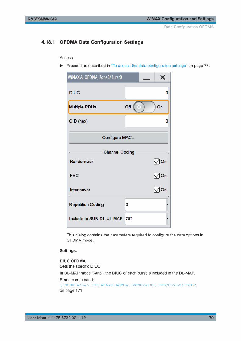
WiMAX Configuration and SettingsR&S®SMW-K49
79User Manual 1175.6732.02 ─ 12
4.18.1 OFDMA Data Configuration Settings
Access:
► Proceed as described in "To access the data configuration settings" on page 78.
This dialog contains the parameters required to configure the data options inOFDMA mode.
Settings:
DIUC OFDMASets the specific DIUC.
In DL-MAP mode "Auto", the DIUC of each burst is included in the DL-MAP.
Remote command: [:SOURce<hw>]:BB:WIMax:AOFDm[:ZONE<st0>]:BURSt<ch0>:DIUCon page 171
Data Configuration OFDMA
WiMAX Configuration and SettingsR&S®SMW-K49
80User Manual 1175.6732.02 ─ 12
UIUC OFDMA( available in uplink direction)
Sets the specific UIUC. The UIUC is used for the UL-MAP, if generated.
Remote command: [:SOURce<hw>]:BB:WIMax:AOFDm[:ZONE<st0>]:BURSt<ch0>:UIUCon page 196
Multiple PDUs OFDMAEnables/disables configuration of multiple PDUs. If this parameter is enabled, multiplePDUs each with own MAC header and CRC are available within one burst (see PDUTable ).
Remote command: [:SOURce<hw>]:BB:WIMax:AOFDm[:ZONE<st0>]:BURSt<ch0>:PDU:STATeon page 187
No. Of PDUs OFDMAAvailable for enabled parameter "Multiple PDUs" only
Sets the number of PDUs in the burst.
Remote command: [:SOURce<hw>]:BB:WIMax:AOFDm[:ZONE<st0>]:BURSt<ch0>:PDU:COUNton page 186
MAC CIDThe command sets the CID (connection control identifier) of the medium access con-trol layer (MAC). The CID identifies a connection to equivalent peers in the MAC of thebase station and subscriber station.
This parameter is identical to the CID set in the MAC Header settings.
Remote command: [:SOURce<hw>]:BB:WIMax:AOFDm[:ZONE<st0>]:BURSt<ch0>:MAC:CIDon page 183[:SOURce<hw>]:BB:WIMax:AOFDm[:ZONE<st0>]:BURSt<ch0>:HARQ<dir0>:MAC:CID on page 180
Configure MACAvailable for disabled parameter "Multiple PDUs" only
Accesses the dialog for configuring the MAC header panel for the selected burst (seeMAC Header Configuration OFDMA).
Remote command: n.a.
Channel Coding RandomizerActivates or deactivates the randomizer applied before channel coding.
Remote command: [:SOURce<hw>]:BB:WIMax:AOFDm[:ZONE<st0>]:BURSt<ch0>:CCODing:RANDomizer on page 168
Data Configuration OFDMA
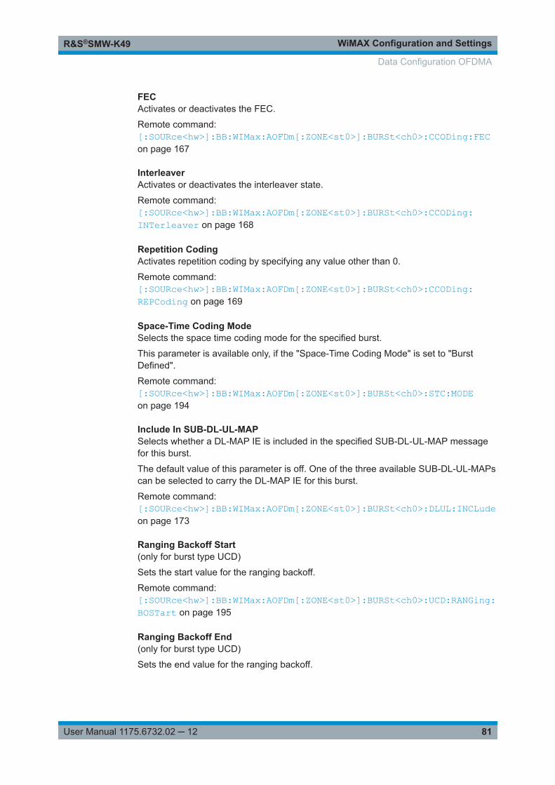
WiMAX Configuration and SettingsR&S®SMW-K49
81User Manual 1175.6732.02 ─ 12
FECActivates or deactivates the FEC.
Remote command: [:SOURce<hw>]:BB:WIMax:AOFDm[:ZONE<st0>]:BURSt<ch0>:CCODing:FECon page 167
InterleaverActivates or deactivates the interleaver state.
Remote command: [:SOURce<hw>]:BB:WIMax:AOFDm[:ZONE<st0>]:BURSt<ch0>:CCODing:INTerleaver on page 168
Repetition CodingActivates repetition coding by specifying any value other than 0.
Remote command: [:SOURce<hw>]:BB:WIMax:AOFDm[:ZONE<st0>]:BURSt<ch0>:CCODing:REPCoding on page 169
Space-Time Coding ModeSelects the space time coding mode for the specified burst.
This parameter is available only, if the "Space-Time Coding Mode" is set to "BurstDefined".
Remote command: [:SOURce<hw>]:BB:WIMax:AOFDm[:ZONE<st0>]:BURSt<ch0>:STC:MODEon page 194
Include In SUB-DL-UL-MAPSelects whether a DL-MAP IE is included in the specified SUB-DL-UL-MAP messagefor this burst.
The default value of this parameter is off. One of the three available SUB-DL-UL-MAPscan be selected to carry the DL-MAP IE for this burst.
Remote command: [:SOURce<hw>]:BB:WIMax:AOFDm[:ZONE<st0>]:BURSt<ch0>:DLUL:INCLudeon page 173
Ranging Backoff Start(only for burst type UCD)
Sets the start value for the ranging backoff.
Remote command: [:SOURce<hw>]:BB:WIMax:AOFDm[:ZONE<st0>]:BURSt<ch0>:UCD:RANGing:BOSTart on page 195
Ranging Backoff End(only for burst type UCD)
Sets the end value for the ranging backoff.
Data Configuration OFDMA
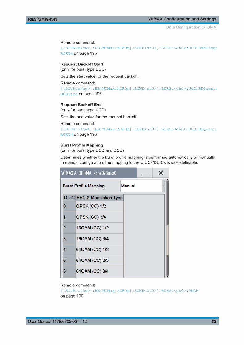
WiMAX Configuration and SettingsR&S®SMW-K49
82User Manual 1175.6732.02 ─ 12
Remote command: [:SOURce<hw>]:BB:WIMax:AOFDm[:ZONE<st0>]:BURSt<ch0>:UCD:RANGing:BOENd on page 195
Request Backoff Start(only for burst type UCD)
Sets the start value for the request backoff.
Remote command: [:SOURce<hw>]:BB:WIMax:AOFDm[:ZONE<st0>]:BURSt<ch0>:UCD:REQuest:BOSTart on page 196
Request Backoff End(only for burst type UCD)
Sets the end value for the request backoff.
Remote command: [:SOURce<hw>]:BB:WIMax:AOFDm[:ZONE<st0>]:BURSt<ch0>:UCD:REQuest:BOENd on page 196
Burst Profile Mapping(only for burst type UCD and DCD)
Determines whether the burst profile mapping is performed automatically or manually.In manual configuration, the mapping to the UIUCs/DUICs is user-definable.
Remote command: [:SOURce<hw>]:BB:WIMax:AOFDm[:ZONE<st0>]:BURSt<ch0>:PMAPon page 190
Data Configuration OFDMA
WiMAX Configuration and SettingsR&S®SMW-K49
83User Manual 1175.6732.02 ─ 12
FEC & Modulation Type ← Burst Profile Mapping(only for burst type UCD and DCD and manual Burst Profile Mapping)
Sets the FEC and the modulation for the selected UIUC/DUIC.
Remote command: [:SOURce<hw>]:BB:WIMax:AOFDm[:ZONE<st0>]:BURSt<ch0>:PMAP:DMODulation<dir0> on page 191[:SOURce<hw>]:BB:WIMax:AOFDm[:ZONE<st0>]:BURSt<ch0>:PMAP:UMODulation<dir0> on page 191
4.18.2 PDU Table
Access:
1. Proceed as described in "To access the data configuration settings" on page 78.
Data Configuration OFDMA
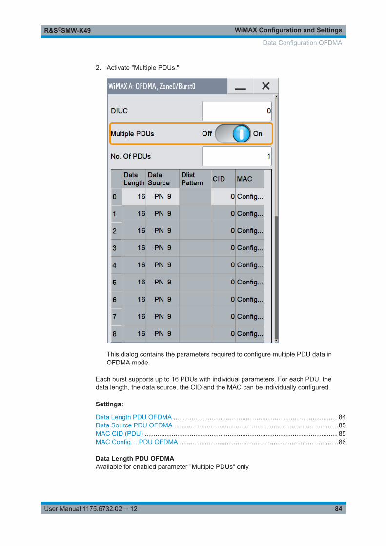
WiMAX Configuration and SettingsR&S®SMW-K49
84User Manual 1175.6732.02 ─ 12
2. Activate "Multiple PDUs."
This dialog contains the parameters required to configure multiple PDU data inOFDMA mode.
Each burst supports up to 16 PDUs with individual parameters. For each PDU, thedata length, the data source, the CID and the MAC can be individually configured.
Settings:
Data Length PDU OFDMA ........................................................................................... 84Data Source PDU OFDMA ...........................................................................................85MAC CID (PDU) ........................................................................................................... 85MAC Config… PDU OFDMA ........................................................................................86
Data Length PDU OFDMAAvailable for enabled parameter "Multiple PDUs" only
Data Configuration OFDMA
WiMAX Configuration and SettingsR&S®SMW-K49
85User Manual 1175.6732.02 ─ 12
Sets the data length for the selected PDU in the burst.
Remote command: [:SOURce<hw>]:BB:WIMax:AOFDm[:ZONE<st0>]:BURSt<ch0>:PDU<dir0>:DLENgth on page 188
Data Source PDU OFDMAAvailable for enabled parameter "Multiple PDUs" only
Sets the PDU data source.
The following standard data sources are available:● "All 0, All 1"
An internally generated sequence containing 0 data or 1 data.● "PNxx"
An internally generated pseudo-random noise sequence.● "Pattern"
An internally generated sequence according to a bit pattern.Use the "Pattern" box to define the bit pattern.
● "Data List/Select DList"A binary data from a data list, internally or externally generated.Select "Select DList" to access the standard "Select List" dialog.– Select the "Select Data List > navigate to the list file *.dm_iqd > Select" to
select an existing data list.– Use the "New" and "Edit" functions to create internally new data list or to edit
an existing one.– Use the standard "File Manager" function to transfer external data lists to the
instrument.See also:● Section "Modulation Data" in the R&S SMW user manual.● Section "File and Data Management" in the R&S SMW user manual.● Section "Data List Editor" in the R&S SMW user manual
Remote command: [:SOURce<hw>]:BB:WIMax:AOFDm[:ZONE<st0>]:BURSt<ch0>:PDU<dir0>:DATA on page 187[:SOURce<hw>]:BB:WIMax:AOFDm[:ZONE<st0>]:BURSt<ch0>:PDU<dir0>:DATA:DSELect on page 188[:SOURce<hw>]:BB:WIMax:AOFDm[:ZONE<st0>]:BURSt<ch0>:PDU<dir0>:DATA:PATTern on page 188
MAC CID (PDU)The command sets the CID (Connection Control Identifier) of the medium access con-trol layer (MAC). The CID identifies a connection to equivalent peers in the MAC of thebase station and subscriber station.
Remote command: [:SOURce<hw>]:BB:WIMax:AOFDm[:ZONE<st0>]:BURSt<ch0>:PDU<dir0>[:MAC]:CID on page 190
Data Configuration OFDMA
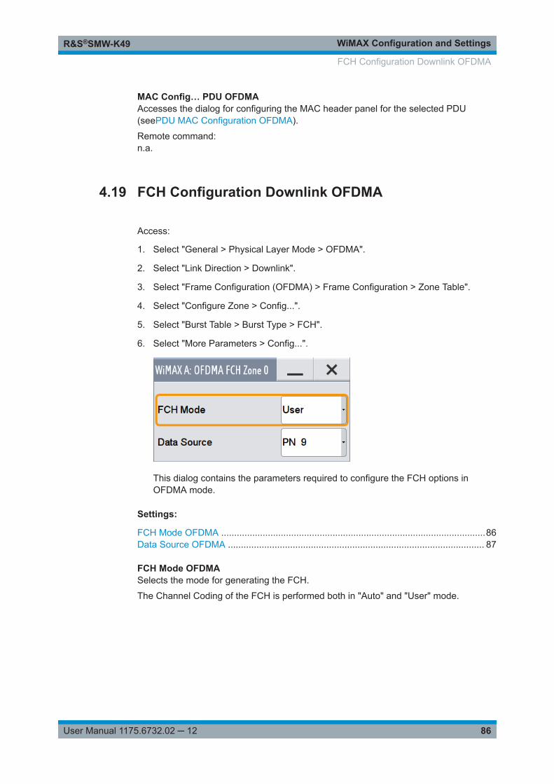
WiMAX Configuration and SettingsR&S®SMW-K49
86User Manual 1175.6732.02 ─ 12
MAC Config… PDU OFDMAAccesses the dialog for configuring the MAC header panel for the selected PDU(seePDU MAC Configuration OFDMA).
Remote command: n.a.
4.19 FCH Configuration Downlink OFDMA
Access:
1. Select "General > Physical Layer Mode > OFDMA".
2. Select "Link Direction > Downlink".
3. Select "Frame Configuration (OFDMA) > Frame Configuration > Zone Table".
4. Select "Configure Zone > Config...".
5. Select "Burst Table > Burst Type > FCH".
6. Select "More Parameters > Config...".
This dialog contains the parameters required to configure the FCH options inOFDMA mode.
Settings:
FCH Mode OFDMA ......................................................................................................86Data Source OFDMA ................................................................................................... 87
FCH Mode OFDMASelects the mode for generating the FCH.
The Channel Coding of the FCH is performed both in "Auto" and "User" mode.
FCH Configuration Downlink OFDMA
WiMAX Configuration and SettingsR&S®SMW-K49
87User Manual 1175.6732.02 ─ 12
"Auto" In "Auto" mode, the DLFP (Downlink Frame Prefix) fields, which formthe FCH, are filled automatically with parameters specified at differentlocations.
The following mapping applies in auto mode:● Used subchannel bitmap
Set to the bitmap specified in the "Configure active Subchannels"panel.
● Repetition_Coding_IndicationSpecifies the DL-MAP repetition coding set in the "Configure DL-MAP" panel.
● Coding_IndicationSpecifies channel coding of the DL-MAP (CC or CTC)
● DL-Map_LengthSet to the number of slots allocated for the DL-MAP.
The FCH is transmitted with QPSK ½ and repetition coding of 4. ForFFT size 128, a reduced FCH is transmitted in one slot.
"User" In "User" mode, the FCH is filled with data specified under "DataSource". It enables any arbitrary data to be sent with the FCH burst.24 bits are read from the data source, these bits are repeated once toform 48 bits. The FCH is transmitted with QPSK ½ and repetition cod-ing of 4. For FFT size 128, a reduced FCH of size 12 bits is transmit-ted in one slot.
Remote command: [:SOURce<hw>]:BB:WIMax:AOFDm:ZONE<st0>:FCH:MODE on page 156
Data Source OFDMASelects data source for the selected bursts.
The following standard data sources are available:● "All 0, All 1"
An internally generated sequence containing 0 data or 1 data.● "PNxx"
An internally generated pseudo-random noise sequence.● "Pattern"
An internally generated sequence according to a bit pattern.Use the "Pattern" box to define the bit pattern.
● "Data List/Select DList"A binary data from a data list, internally or externally generated.Select "Select DList" to access the standard "Select List" dialog.– Select the "Select Data List > navigate to the list file *.dm_iqd > Select" to
select an existing data list.– Use the "New" and "Edit" functions to create internally new data list or to edit
an existing one.– Use the standard "File Manager" function to transfer external data lists to the
instrument.See also:● Section "Modulation Data" in the R&S SMW user manual.● Section "File and Data Management" in the R&S SMW user manual.● Section "Data List Editor" in the R&S SMW user manual
FCH Configuration Downlink OFDMA
WiMAX Configuration and SettingsR&S®SMW-K49
88User Manual 1175.6732.02 ─ 12
Remote command: [:SOURce<hw>]:BB:WIMax:AOFDm[:ZONE<st0>]:BURSt<ch0>:DATAon page 169[:SOURce<hw>]:BB:WIMax:AOFDm[:ZONE<st0>]:BURSt<ch0>:DATA:PATTernon page 171[:SOURce<hw>]:BB:WIMax:AOFDm[:ZONE<st0>]:BURSt<ch0>:DATA:DSELecton page 170
4.20 DL-MAP Configuration Downlink OFDMA
Access:
1. Select "General > Physical Layer Mode > OFDMA".
2. Select "Link Direction > Downlink".
3. Select "Frame Configuration (OFDMA) > Frame Configuration > Zone Table".
4. Select "Configure Zone > Config...".
5. Select "Burst Table > Burst Type > DL-MAP".
DL-MAP Configuration Downlink OFDMA
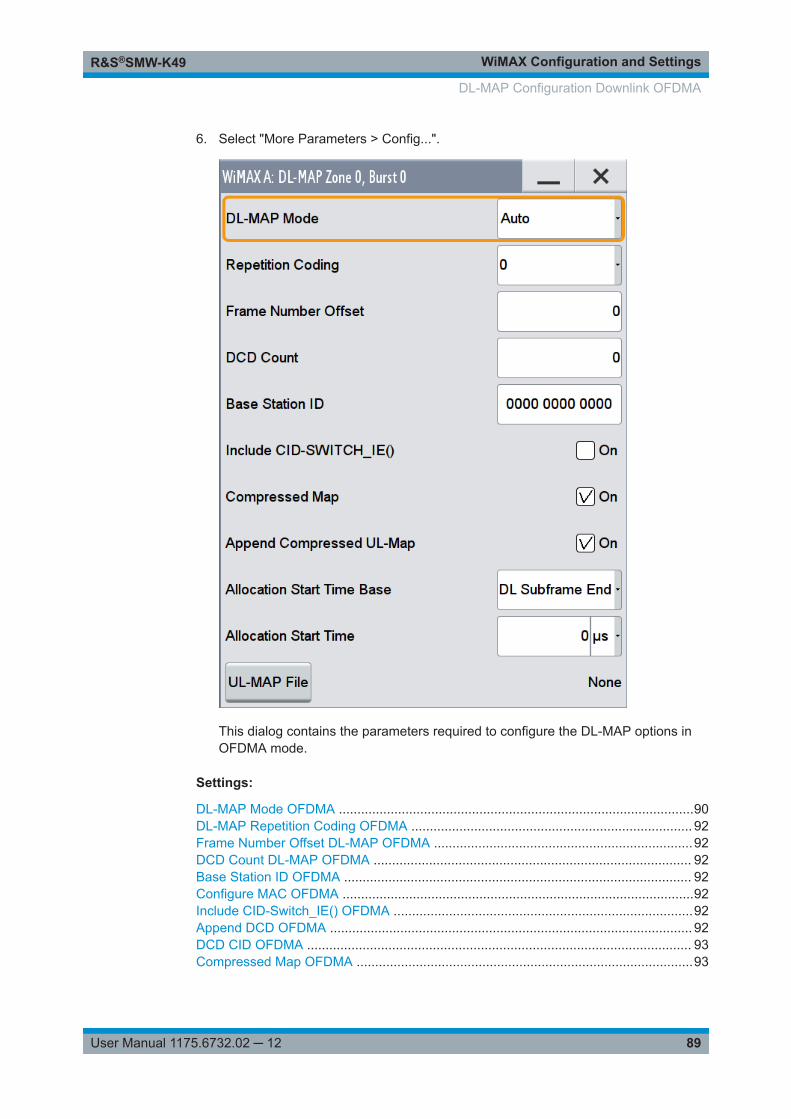
WiMAX Configuration and SettingsR&S®SMW-K49
89User Manual 1175.6732.02 ─ 12
6. Select "More Parameters > Config...".
This dialog contains the parameters required to configure the DL-MAP options inOFDMA mode.
Settings:
DL-MAP Mode OFDMA ................................................................................................90DL-MAP Repetition Coding OFDMA ............................................................................ 92Frame Number Offset DL-MAP OFDMA ......................................................................92DCD Count DL-MAP OFDMA ...................................................................................... 92Base Station ID OFDMA .............................................................................................. 92Configure MAC OFDMA ...............................................................................................92Include CID-Switch_IE() OFDMA .................................................................................92Append DCD OFDMA .................................................................................................. 92DCD CID OFDMA ........................................................................................................ 93Compressed Map OFDMA ...........................................................................................93
DL-MAP Configuration Downlink OFDMA
WiMAX Configuration and SettingsR&S®SMW-K49
90User Manual 1175.6732.02 ─ 12
Append Compressed UL-Map OFDMA ........................................................................93Allocation Start Timebase OFDMA .............................................................................. 93Allocation Start Time OFDMA ...................................................................................... 93UL-MAP File OFDMA ...................................................................................................93
DL-MAP Mode OFDMASelects the mode for generating the DL-MAP.
Channel Coding of the DL-MAP is performed both in "Auto" and "User" mode.
DL-MAP Configuration Downlink OFDMA
WiMAX Configuration and SettingsR&S®SMW-K49
91User Manual 1175.6732.02 ─ 12
"Auto" In "Auto" mode, the DL-MAP is filled automatically with parametersspecified at different locations.
The following mapping applies in auto mode:● Frame duration code
Specified by the frame duration set in the WiMAX main panel.● Frame number
Starts with the value specified by "Frame Number Offset" in thefirst generated frame and advances by 1 in every following frame.
● DCD CountDirectly set by the "DCD Count" field.
● Base Station ID48 bits specified by the "Base Station ID" field.
● No. OFDMA symbolsSet to the total number of OFDMA symbols in all downlink zones
For each burst:● DIUC
Set to the "DIUC" field in the "More Param" Panel.● CID
Set to the "CID" field in the"More Param" panel. This field is onlyincluded if "Include CID-SWITCH_IE()" is active.
● OFDMA Symbol offsetSet to "Offset Symb" +1 for the first zone and to the absolute sym-bol offset in all other zones.
● Subchannel offsetSet to "Offset Subch" of the burst table.
● BoostingDepends on the "Boost" setting of the corresponding burst.The following mapping applies:000: 0dB001: +6dB010: -6dB011: +9dB100: +3dB101: -3dB110: -9dB111: -12dB000 is set if any other value is specified for "Boost".
● No. OFDMA SymbolsSet to "No. of Symb" of the burst table.
● No. SubchannelsSet to "No. of Subch" of the burst table.
● Repetition coding IndicationSet to repetition coding in the "More Param" panel.
"User" In "User" mode, the DL-MAP is filled with data specified under "DataSource". It enables any arbitrary data to be sent with the DL-MAPburst.
Remote command: [:SOURce<hw>]:BB:WIMax:AOFDm[:ZONE<st0>]:DLMap:MODE on page 203
DL-MAP Configuration Downlink OFDMA
WiMAX Configuration and SettingsR&S®SMW-K49
92User Manual 1175.6732.02 ─ 12
DL-MAP Repetition Coding OFDMARepetition coding can be activated for the DL-MAP by specifying any value other than0.
Remote command: [:SOURce<hw>]:BB:WIMax:AOFDm[:ZONE<st0>]:DLMap:REPCodingon page 204
Frame Number Offset DL-MAP OFDMASets the frame number offset.
This value is added to the current frame number of the sequence. The result is used asframe number in the DL-MAP (in "Auto" mode).
Remote command: [:SOURce<hw>]:BB:WIMax:AOFDm[:ZONE<st0>]:DLMap:FNOFfseton page 203
DCD Count DL-MAP OFDMASets the DCD count value.
This value is used for the corresponding DL-MAP field (in "Auto" mode).
Remote command: [:SOURce<hw>]:BB:WIMax:AOFDm[:ZONE<st0>]:DLMap:DATA:DCD[:COUNt]on page 202
Base Station ID OFDMASets the Base Station ID.
This value is used for the corresponding DL-MAP field in ("Auto" mode).
Remote command: [:SOURce<hw>]:BB:WIMax:AOFDm[:ZONE<st0>]:DLMap:BSID on page 200
Configure MAC OFDMACalls the dialog for configuring the Mac header panel for the DL-MAP (refer to Chap-ter 4.27, "MAC Header Configuration OFDMA", on page 113)
Remote command: n.a.
Include CID-Switch_IE() OFDMAIncludes/excludes the CID-Switch_IE().
Remote command: [:SOURce<hw>]:BB:WIMax:AOFDm[:ZONE<st0>]:DLMap:IIE:STATeon page 203
Append DCD OFDMAIf activated, the DCD is appended to the DL-MAP. The DCD message carries its ownMAC header and CRC, but is included within the DL-MAP burst.
Remote command: [:SOURce<hw>]:BB:WIMax:AOFDm[:ZONE<st0>]:DLMap:DCD:STATeon page 202
DL-MAP Configuration Downlink OFDMA
WiMAX Configuration and SettingsR&S®SMW-K49
93User Manual 1175.6732.02 ─ 12
DCD CID OFDMA(only if "Append DCD > On")
Enters the value for the DCD CID.
This CID (connection control identifier) is independent from the DL-Map CID and isonly used for the DCD message.
Remote command: [:SOURce<hw>]:BB:WIMax:AOFDm[:ZONE<st0>]:DLMap:DCD:CID on page 202
Compressed Map OFDMAIf activated, a compressed map is generated instead of a normal map.
Remote command: [:SOURce<hw>]:BB:WIMax:AOFDm[:ZONE<st0>]:DLMap:COMPressed:STATeon page 201
Append Compressed UL-Map OFDMA(only if "Compressed Map > On")
If activated, a compressed UL-Map is appended to the DL-Map.
Remote command: [:SOURce<hw>]:BB:WIMax:AOFDm[:ZONE<st0>]:DLMap:COMPressed:ULMap:STATe on page 201
Allocation Start Timebase OFDMASelects the allocation start timebase, required for the UL-Map appended to the DL-Map. The "Allocation Start Time" field of the UL-Map specifies the start of the uplinksubframe.
If "Start Timebase = DL Subframe End", the "Allocation Start Time" of the UL-Map isset to the end of the downlink subframe+ the value set with the parameter AllocationStart Time OFDMA .
When "Start Timebase = Frame Start", the allocation start Time of the UL-Map is set tothe beginning of the frame+ the value set with the parameter Allocation Start TimeOFDMA .
Remote command: [:SOURce<hw>]:BB:WIMax:AOFDm[:ZONE<st0>]:DLMap:COMPressed:AMODeon page 200
Allocation Start Time OFDMASets the allocation start time in the UL-Map, appended to the DL-Map.
Remote command: [:SOURce<hw>]:BB:WIMax:AOFDm[:ZONE<st0>]:DLMap:COMPressed:ATIMeon page 200
UL-MAP File OFDMAAccess the dialog for selecting the UL-MAP file.
Remote command: [:SOURce<hw>]:BB:WIMax:AOFDm[:ZONE<st0>]:DLMap:COMPressed:ULMap:DSELect on page 201
DL-MAP Configuration Downlink OFDMA
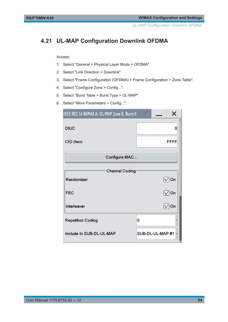
WiMAX Configuration and SettingsR&S®SMW-K49
94User Manual 1175.6732.02 ─ 12
4.21 UL-MAP Configuration Downlink OFDMA
Access:
1. Select "General > Physical Layer Mode > OFDMA".
2. Select "Link Direction > Downlink".
3. Select "Frame Configuration (OFDMA) > Frame Configuration > Zone Table".
4. Select "Configure Zone > Config...".
5. Select "Burst Table > Burst Type > UL-MAP".
6. Select "More Parameters > Config...".
UL-MAP Configuration Downlink OFDMA
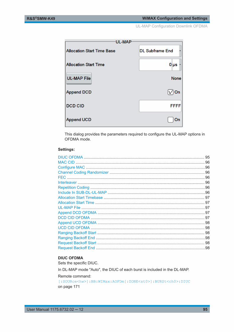
WiMAX Configuration and SettingsR&S®SMW-K49
95User Manual 1175.6732.02 ─ 12
This dialog provides the parameters required to configure the UL-MAP options inOFDMA mode.
Settings:
DIUC OFDMA .............................................................................................................. 95MAC CID ...................................................................................................................... 96Configure MAC .............................................................................................................96Channel Coding Randomizer ....................................................................................... 96FEC .............................................................................................................................. 96Interleaver .................................................................................................................... 96Repetition Coding .........................................................................................................96Include In SUB-DL-UL-MAP .........................................................................................96Allocation Start Timebase ............................................................................................ 97Allocation Start Time .................................................................................................... 97UL-MAP File .................................................................................................................97Append DCD OFDMA .................................................................................................. 97DCD CID OFDMA ........................................................................................................ 97Append UCD OFDMA .................................................................................................. 98UCD CID OFDMA ........................................................................................................ 98Ranging Backoff Start .................................................................................................. 98Ranging Backoff End ....................................................................................................98Request Backoff Start .................................................................................................. 98Request Backoff End ....................................................................................................98
DIUC OFDMASets the specific DIUC.
In DL-MAP mode "Auto", the DIUC of each burst is included in the DL-MAP.
Remote command: [:SOURce<hw>]:BB:WIMax:AOFDm[:ZONE<st0>]:BURSt<ch0>:DIUCon page 171
UL-MAP Configuration Downlink OFDMA
WiMAX Configuration and SettingsR&S®SMW-K49
96User Manual 1175.6732.02 ─ 12
MAC CIDThe command sets the CID (connection control identifier) of the medium access con-trol layer (MAC). The CID identifies a connection to equivalent peers in the MAC of thebase station and subscriber station.
This parameter is identical to the CID set in the MAC Header settings.
Remote command: [:SOURce<hw>]:BB:WIMax:AOFDm[:ZONE<st0>]:BURSt<ch0>:MAC:CIDon page 183[:SOURce<hw>]:BB:WIMax:AOFDm[:ZONE<st0>]:BURSt<ch0>:HARQ<dir0>:MAC:CID on page 180
Configure MACAccesses the dialog for configuring the MAC header panel for the selected burst.(Refer to Chapter 4.27, "MAC Header Configuration OFDMA", on page 113.)
Remote command: n.a.
Channel Coding RandomizerActivates or deactivates the randomizer applied before channel coding.
Remote command: [:SOURce<hw>]:BB:WIMax:AOFDm[:ZONE<st0>]:BURSt<ch0>:CCODing:RANDomizer on page 168
FECActivates or deactivates the FEC.
Remote command: [:SOURce<hw>]:BB:WIMax:AOFDm[:ZONE<st0>]:BURSt<ch0>:CCODing:FECon page 167
InterleaverActivates or deactivates the interleaver state.
Remote command: [:SOURce<hw>]:BB:WIMax:AOFDm[:ZONE<st0>]:BURSt<ch0>:CCODing:INTerleaver on page 168
Repetition CodingActivates repetition coding by specifying any value other than 0.
Remote command: [:SOURce<hw>]:BB:WIMax:AOFDm[:ZONE<st0>]:BURSt<ch0>:CCODing:REPCoding on page 169
Include In SUB-DL-UL-MAPSelects whether a DL-MAP IE is included in the specified SUB-DL-UL-MAP messagefor this burst.
The default value of this parameter is off. One of the three available SUB-DL-UL-MAPscan be selected to carry the DL-MAP IE for this burst.
UL-MAP Configuration Downlink OFDMA
WiMAX Configuration and SettingsR&S®SMW-K49
97User Manual 1175.6732.02 ─ 12
Remote command: [:SOURce<hw>]:BB:WIMax:AOFDm[:ZONE<st0>]:BURSt<ch0>:DLUL:INCLudeon page 173
Allocation Start TimebaseSelects the allocation start timebase. The "Allocation Start Time" field of the UL-MAPspecifies the start of the uplink subframe.
If "Start Timebase = DL Subframe End", the "Allocation Start Time" of the UL-Map isset to the end of the downlink subframe+ the value set with the parameter AllocationStart Time .
When "Start Timebase = Frame Start", the allocation start Time of the UL-Map is set tothe beginning of the frame+ the value set with the parameter Allocation Start Time .
Remote command: [:SOURce<hw>]:BB:WIMax:AOFDm[:ZONE<st0>]:BURSt<ch0>:ULMap:AMODeon page 196
Allocation Start TimeSets the allocation start time in the UL-MAP.
Remote command: [:SOURce<hw>]:BB:WIMax:AOFDm[:ZONE<st0>]:BURSt<ch0>:ULMap:ATIMeon page 197
UL-MAP FileAccesses the dialog for selecting the UL-MAP file.
Remote command: n.a.
Append DCD OFDMAIf activated, the DCD is appended to the UL-MAP. The DCD message is transmittedwith its own MAC header and CRC, included in the same burst allocation used by theUL-MAP.
Remote command: [:SOURce<hw>]:BB:WIMax:AOFDm[:ZONE<st0>]:BURSt<ch0>:ULMap:DCD:STATe on page 197
DCD CID OFDMA("Append DCD > On")
Enters the value for the DCD CID.
This CID (connection control identifier) is independent from the UL-Map CID and onlyused for the DCD.
Remote command: [:SOURce<hw>]:BB:WIMax:AOFDm[:ZONE<st0>]:BURSt<ch0>:ULMap:DCD:CID on page 197
UL-MAP Configuration Downlink OFDMA
WiMAX Configuration and SettingsR&S®SMW-K49
98User Manual 1175.6732.02 ─ 12
Append UCD OFDMAIf activated, the UCD is appended to the UL-MAP. The UCD message is transmittedwith its own MAC header and CRC, included in the same burst allocation used by theUL-MAP.
Remote command: [:SOURce<hw>]:BB:WIMax:AOFDm[:ZONE<st0>]:BURSt<ch0>:ULMap:UCD:STATe on page 199
UCD CID OFDMA("Append DCD > On")
Enters the value for the UCD CID.
This CID (connection control identifier) is independent from the DL-Map CID and onlyused for the UCD.
Remote command: [:SOURce<hw>]:BB:WIMax:AOFDm[:ZONE<st0>]:BURSt<ch0>:ULMap:UCD:CID on page 199
Ranging Backoff StartSets the start value for the ranging backoff.
Remote command: [:SOURce<hw>]:BB:WIMax:AOFDm[:ZONE<st0>]:BURSt<ch0>:ULMap:RANGing:BOSTart on page 198
Ranging Backoff EndSets the end value for the ranging backoff.
Remote command: [:SOURce<hw>]:BB:WIMax:AOFDm[:ZONE<st0>]:BURSt<ch0>:ULMap:RANGing:BOENd on page 198
Request Backoff StartSets the start value for the request backoff.
Remote command: [:SOURce<hw>]:BB:WIMax:AOFDm[:ZONE<st0>]:BURSt<ch0>:ULMap:REQuest:BOSTart on page 199
Request Backoff EndSets the end value for the request backoff.
Remote command: [:SOURce<hw>]:BB:WIMax:AOFDm[:ZONE<st0>]:BURSt<ch0>:ULMap:REQuest:BOENd on page 198
UL-MAP Configuration Downlink OFDMA
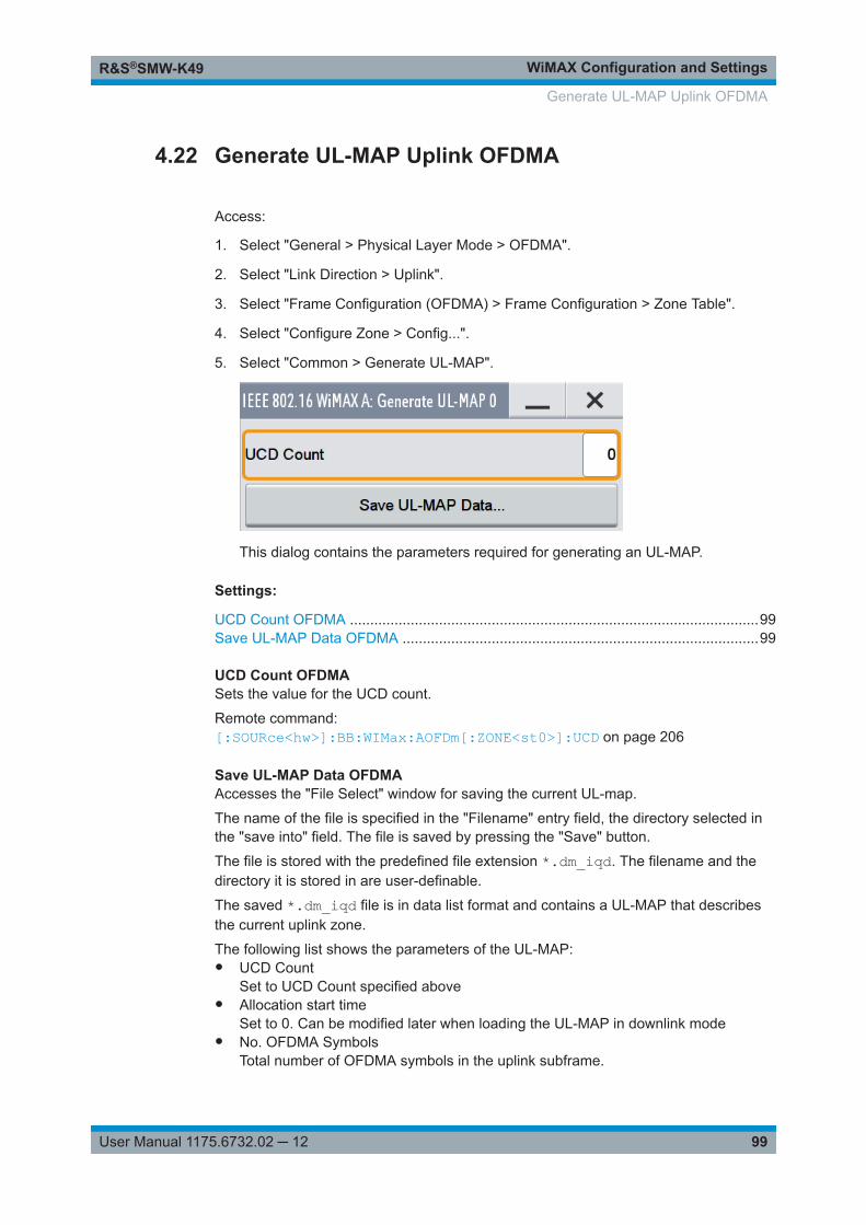
WiMAX Configuration and SettingsR&S®SMW-K49
99User Manual 1175.6732.02 ─ 12
4.22 Generate UL-MAP Uplink OFDMA
Access:
1. Select "General > Physical Layer Mode > OFDMA".
2. Select "Link Direction > Uplink".
3. Select "Frame Configuration (OFDMA) > Frame Configuration > Zone Table".
4. Select "Configure Zone > Config...".
5. Select "Common > Generate UL-MAP".
This dialog contains the parameters required for generating an UL-MAP.
Settings:
UCD Count OFDMA .....................................................................................................99Save UL-MAP Data OFDMA ........................................................................................99
UCD Count OFDMASets the value for the UCD count.
Remote command: [:SOURce<hw>]:BB:WIMax:AOFDm[:ZONE<st0>]:UCD on page 206
Save UL-MAP Data OFDMAAccesses the "File Select" window for saving the current UL-map.
The name of the file is specified in the "Filename" entry field, the directory selected inthe "save into" field. The file is saved by pressing the "Save" button.
The file is stored with the predefined file extension *.dm_iqd. The filename and thedirectory it is stored in are user-definable.
The saved *.dm_iqd file is in data list format and contains a UL-MAP that describesthe current uplink zone.
The following list shows the parameters of the UL-MAP:● UCD Count
Set to UCD Count specified above● Allocation start time
Set to 0. Can be modified later when loading the UL-MAP in downlink mode● No. OFDMA Symbols
Total number of OFDMA symbols in the uplink subframe.
Generate UL-MAP Uplink OFDMA
WiMAX Configuration and SettingsR&S®SMW-K49
100User Manual 1175.6732.02 ─ 12
● CIDCID from the "More Param" panel for each burst
● UIUCUIUC from the "More Param" panel for each burst or 12 for ranging.
For ranging bursts:● OFDMA Symbol offset
Symbol offset relative to allocation start time● Subchannel offset
Lowest subchannel used for ranging allocation● No. OFDMA symbols
Symbols in ranging allocation● No. Subchannels
Subchannels in ranging allocation● Ranging method
Defined by the "Opportunity Size" in the "Ranging" panel.For data bursts:● Duration
Burst duration in slots● Repetition coding indication
Repetition coding from the "More Param" panel for each burstGenerating a valid UL-MAPThe following steps are required to generate a valid UL-MAP:● Switch to uplink mode● Define the layout of the uplink zone by setting a number of bursts and specifying
the parameters above for each burst● Select "Generate UL-MAP" and save the UL-MAP to a file.● Switch to downlink mode● Set one of the downlinks bursts to "Burst Type UL-MAP"● Open the "More Param" panel● Select "UL-MAP File" and load the file created before.The downlink zone is then transmitting a UL-MAP that specifies the uplink structuredefined in uplink mode before.
Remote command: [:SOURce<hw>]:BB:WIMax:AOFDm[:ZONE<st0>]:ULMap:CREate on page 206
4.23 Ranging Uplink OFDMA
Access:
1. Select "General > Physical Layer Mode > OFDMA".
2. Select "Link Direction > Uplink".
3. Select "Frame Configuration (OFDMA) > Frame Configuration > Zone Table".
4. Select "Configure Zone > Config...".
Ranging Uplink OFDMA
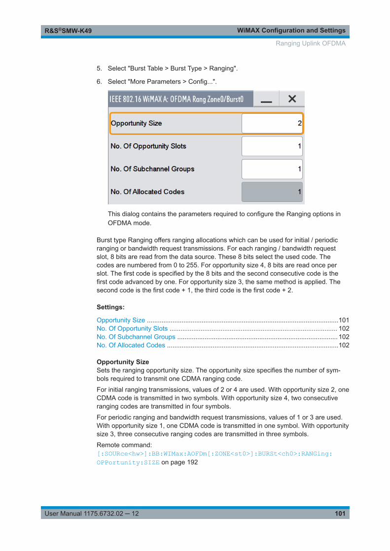
WiMAX Configuration and SettingsR&S®SMW-K49
101User Manual 1175.6732.02 ─ 12
5. Select "Burst Table > Burst Type > Ranging".
6. Select "More Parameters > Config...".
This dialog contains the parameters required to configure the Ranging options inOFDMA mode.
Burst type Ranging offers ranging allocations which can be used for initial / periodicranging or bandwidth request transmissions. For each ranging / bandwidth requestslot, 8 bits are read from the data source. These 8 bits select the used code. Thecodes are numbered from 0 to 255. For opportunity size 4, 8 bits are read once perslot. The first code is specified by the 8 bits and the second consecutive code is thefirst code advanced by one. For opportunity size 3, the same method is applied. Thesecond code is the first code + 1, the third code is the first code + 2.
Settings:
Opportunity Size .........................................................................................................101No. Of Opportunity Slots ............................................................................................ 102No. Of Subchannel Groups ........................................................................................ 102No. Of Allocated Codes ..............................................................................................102
Opportunity SizeSets the ranging opportunity size. The opportunity size specifies the number of sym-bols required to transmit one CDMA ranging code.
For initial ranging transmissions, values of 2 or 4 are used. With opportunity size 2, oneCDMA code is transmitted in two symbols. With opportunity size 4, two consecutiveranging codes are transmitted in four symbols.
For periodic ranging and bandwidth request transmissions, values of 1 or 3 are used.With opportunity size 1, one CDMA code is transmitted in one symbol. With opportunitysize 3, three consecutive ranging codes are transmitted in three symbols.
Remote command: [:SOURce<hw>]:BB:WIMax:AOFDm[:ZONE<st0>]:BURSt<ch0>:RANGing:OPPortunity:SIZE on page 192
Ranging Uplink OFDMA

WiMAX Configuration and SettingsR&S®SMW-K49
102User Manual 1175.6732.02 ─ 12
No. Of Opportunity SlotsThe number of opportunity slots defines the length of the ranging allocation:
Length of Ranging Allocation = OpportunitySize * NoOfOpportunitySlots OFDMA sym-bols.
Remote command: [:SOURce<hw>]:BB:WIMax:AOFDm[:ZONE<st0>]:BURSt<ch0>:RANGing:OPPortunity:SLOTcount on page 193
No. Of Subchannel GroupsSets the number of subchannel groups used in the ranging allocation. In PUSC mode,six subchannels form one subchannel group.
Remote command: [:SOURce<hw>]:BB:WIMax:AOFDm[:ZONE<st0>]:BURSt<ch0>:RANGing:SCGCount on page 193
No. Of Allocated CodesDisplays the number of allocated codes. The number of codes is "NoOfOpportunity-Slots" * "NoOfSubchannelGroups".
Consecutive codes of opportunity sizes 3 and 4 are not accounted.
Remote command: [:SOURce<hw>]:BB:WIMax:AOFDm[:ZONE<st0>]:BURSt<ch0>:RANGing:ACODe? on page 192
4.24 HARQ Configuration OFDMA
This dialog provides all parameters to configure the HARQ options in OFDMA mode.The selected HARQ mode determines the parameters available in the HARQ-sub bursttable.
To access this dialog
Access:
1. Select "General > Physical Layer Mode > OFDMA".
2. Select "Frame Configuration (OFDMA) > Frame Configuration > Zone Table".
3. Select "Configure Zone > Config...".
4. Select "Burst Table > Burst Type > HARQ".
5. Select "More Parameters > Config...".
Content
● OFDMA HARQ Settings........................................................................................103● HARQ Sub-Burst Table......................................................................................... 105
HARQ Configuration OFDMA
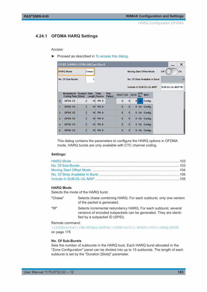
WiMAX Configuration and SettingsR&S®SMW-K49
103User Manual 1175.6732.02 ─ 12
4.24.1 OFDMA HARQ Settings
Access:
► Proceed as described in To access this dialog.
This dialog contains the parameters to configure the HARQ options in OFDMAmode. HARQ bursts are only available with CTC channel coding.
Settings:
HARQ Mode ...............................................................................................................103No. Of Sub-Bursts ...................................................................................................... 103Moving Start Offset Mode ...........................................................................................104No. Of Slots Available In Burst ...................................................................................105Include In SUB-DL-UL-MAP .......................................................................................105
HARQ ModeSelects the mode of the HARQ burst.
"Chase" Selects chase combining HARQ. For each subburst, only one versionof the packet is generated.
"IR" Selects incremental redundancy HARQ. For each subburst, severalversions of encoded subpackets can be generated. They are identi-fied by a subpacket ID (SPID).
Remote command: [:SOURce<hw>]:BB:WIMax:AOFDm[:ZONE<st0>]:BURSt<ch0>:HARQ:MODEon page 175
No. Of Sub-BurstsSets the number of subbursts in the HARQ bust. Each HARQ burst allocated in the"Zone Configuration" panel can be divided into up to 15 subbursts. The length of eachsubburst is set by the "Duration [Slots]" parameter.
HARQ Configuration OFDMA
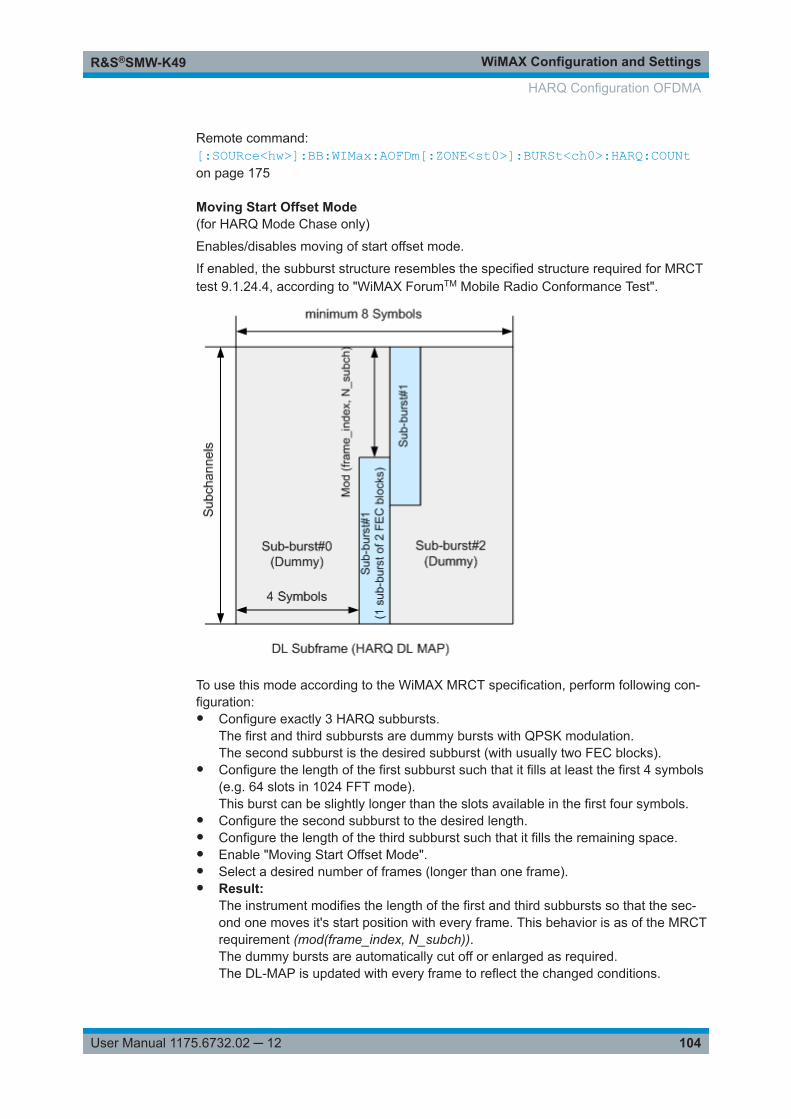
WiMAX Configuration and SettingsR&S®SMW-K49
104User Manual 1175.6732.02 ─ 12
Remote command: [:SOURce<hw>]:BB:WIMax:AOFDm[:ZONE<st0>]:BURSt<ch0>:HARQ:COUNton page 175
Moving Start Offset Mode(for HARQ Mode Chase only)
Enables/disables moving of start offset mode.
If enabled, the subburst structure resembles the specified structure required for MRCTtest 9.1.24.4, according to "WiMAX ForumTM Mobile Radio Conformance Test".
To use this mode according to the WiMAX MRCT specification, perform following con-figuration:● Configure exactly 3 HARQ subbursts.
The first and third subbursts are dummy bursts with QPSK modulation.The second subburst is the desired subburst (with usually two FEC blocks).
● Configure the length of the first subburst such that it fills at least the first 4 symbols(e.g. 64 slots in 1024 FFT mode).This burst can be slightly longer than the slots available in the first four symbols.
● Configure the second subburst to the desired length.● Configure the length of the third subburst such that it fills the remaining space.● Enable "Moving Start Offset Mode".● Select a desired number of frames (longer than one frame).● Result:
The instrument modifies the length of the first and third subbursts so that the sec-ond one moves it's start position with every frame. This behavior is as of the MRCTrequirement (mod(frame_index, N_subch)).The dummy bursts are automatically cut off or enlarged as required.The DL-MAP is updated with every frame to reflect the changed conditions.
HARQ Configuration OFDMA
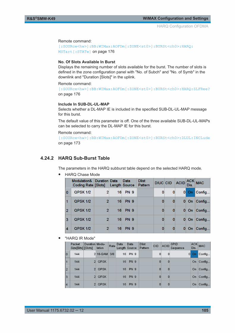
WiMAX Configuration and SettingsR&S®SMW-K49
105User Manual 1175.6732.02 ─ 12
Remote command: [:SOURce<hw>]:BB:WIMax:AOFDm[:ZONE<st0>]:BURSt<ch0>:HARQ:MSTart[:STATe] on page 176
No. Of Slots Available In BurstDisplays the remaining number of slots available for the burst. The number of slots isdefined in the zone configuration panel with "No. of Subch" and "No. of Symb" in thedownlink and "Duration [Slots]" in the uplink.
Remote command: [:SOURce<hw>]:BB:WIMax:AOFDm[:ZONE<st0>]:BURSt<ch0>:HARQ:SLFRee?on page 176
Include In SUB-DL-UL-MAPSelects whether a DL-MAP IE is included in the specified SUB-DL-UL-MAP messagefor this burst.
The default value of this parameter is off. One of the three available SUB-DL-UL-MAPscan be selected to carry the DL-MAP IE for this burst.
Remote command: [:SOURce<hw>]:BB:WIMax:AOFDm[:ZONE<st0>]:BURSt<ch0>:DLUL:INCLudeon page 173
4.24.2 HARQ Sub-Burst Table
The parameters in the HARQ subburst table depend on the selected HARQ mode.● HARQ Chase Mode
● "HARQ IR Mode"
HARQ Configuration OFDMA
WiMAX Configuration and SettingsR&S®SMW-K49
106User Manual 1175.6732.02 ─ 12
Settings:
Sub-Burst Index ......................................................................................................... 106Modulation & Coding Rate ......................................................................................... 106Packet Size [Bits] ....................................................................................................... 106Duration [Slots] ...........................................................................................................106Modulation ..................................................................................................................106Rate ............................................................................................................................107Data Length ................................................................................................................107Data Source ............................................................................................................... 107DIUC .......................................................................................................................... 108MAC CID .................................................................................................................... 108ACID ...........................................................................................................................108SPID Sequence ..........................................................................................................108ACK Disable ...............................................................................................................109MAC ........................................................................................................................... 109
Sub-Burst IndexDisplays the consecutive subburst index from 0 to 14.
All the rows are always displayed, even if the subbursts are inactive. They areswitched on and off by the selection of "No. of Sub-Bursts" above the table. The activesubbursts are highlighted.
Remote command: n.a.
Modulation & Coding Rate(for "HARQ Chase Mode")
Sets the subburst modulation and coding rate.
Remote command: [:SOURce<hw>]:BB:WIMax:AOFDm[:ZONE<st0>]:BURSt<ch0>:HARQ<dir0>:MODRate on page 181
Packet Size [Bits](for "HARQ IR Mode")
Sets the HARQ subburst packet size (in bits).
Remote command: [:SOURce<hw>]:BB:WIMax:AOFDm[:ZONE<st0>]:BURSt<ch0>:HARQ<dir0>:PSIZe on page 182
Duration [Slots]Sets the duration of the subbursts in slots. The duration range is dynamic and dependson the selected link direction and packet size.
Remote command: [:SOURce<hw>]:BB:WIMax:AOFDm[:ZONE<st0>]:BURSt<ch0>:HARQ<dir0>:SLOTcount on page 183
Modulation(for "HARQ IR Mode")
HARQ Configuration OFDMA
WiMAX Configuration and SettingsR&S®SMW-K49
107User Manual 1175.6732.02 ─ 12
Displays the subburst modulation.
The modulation is determined by the parameters "Packet Size" and "Duration" andcannot be altered directly.
Remote command: [:SOURce<hw>]:BB:WIMax:AOFDm[:ZONE<st0>]:BURSt<ch0>:HARQ<dir0>:FORMat? on page 179
Rate(for "HARQ IR Mode")
Displays the subburst code rate. The code rate is determined by the parameters"Packet Size" and "Duration" and cannot be altered directly
Remote command: [:SOURce<hw>]:BB:WIMax:AOFDm[:ZONE<st0>]:BURSt<ch0>:HARQ<dir0>:RATE? on page 182
Data LengthSets the data length of the subburst. The data length range is dynamic and dependson the packet size and the MAC header state.
Remote command: [:SOURce<hw>]:BB:WIMax:AOFDm[:ZONE<st0>]:BURSt<ch0>:HARQ<dir0>:DLENgth on page 179
Data SourceSelects data source for the selected subbursts.
The following standard data sources are available:● "All 0, All 1"
An internally generated sequence containing 0 data or 1 data.● "PNxx"
An internally generated pseudo-random noise sequence.● "Pattern"
An internally generated sequence according to a bit pattern.Use the "Pattern" box to define the bit pattern.
● "Data List/Select DList"A binary data from a data list, internally or externally generated.Select "Select DList" to access the standard "Select List" dialog.– Select the "Select Data List > navigate to the list file *.dm_iqd > Select" to
select an existing data list.– Use the "New" and "Edit" functions to create internally new data list or to edit
an existing one.– Use the standard "File Manager" function to transfer external data lists to the
instrument.See also:● Section "Modulation Data" in the R&S SMW user manual.● Section "File and Data Management" in the R&S SMW user manual.● Section "Data List Editor" in the R&S SMW user manual
HARQ Configuration OFDMA
WiMAX Configuration and SettingsR&S®SMW-K49
108User Manual 1175.6732.02 ─ 12
Remote command: [:SOURce<hw>]:BB:WIMax:AOFDm[:ZONE<st0>]:BURSt<ch0>:HARQ<dir0>:DATA on page 177[:SOURce<hw>]:BB:WIMax:AOFDm[:ZONE<st0>]:BURSt<ch0>:HARQ<dir0>:DATA:PATTern on page 178[:SOURce<hw>]:BB:WIMax:AOFDm[:ZONE<st0>]:BURSt<ch0>:HARQ<dir0>:DATA:DSELect on page 178
DIUC(for HARQ Chase Mode only)
Sets the DIUC ("Downlink Interval User Code") for the specified subburst.
Remote command: [:SOURce<hw>]:BB:WIMax:AOFDm[:ZONE<st0>]:BURSt<ch0>:HARQ<dir0>:DIUC on page 179
MAC CIDThe command sets the CID (connection control identifier) of the medium access con-trol layer (MAC). The CID identifies a connection to equivalent peers in the MAC of thebase station and subscriber station.
This parameter is identical to the CID set in the MAC Header settings.
Remote command: [:SOURce<hw>]:BB:WIMax:AOFDm[:ZONE<st0>]:BURSt<ch0>:MAC:CIDon page 183[:SOURce<hw>]:BB:WIMax:AOFDm[:ZONE<st0>]:BURSt<ch0>:HARQ<dir0>:MAC:CID on page 180
ACIDSets the HARQ channel identifier for the specified subburst.
Remote command: [:SOURce<hw>]:BB:WIMax:AOFDm[:ZONE<st0>]:BURSt<ch0>:HARQ<dir0>:ACID on page 177
SPID Sequence(for "HARQ IR Mode")
Sets the subpacket ID sequence which is used to select the generated subpacket outof the four possible subpackets for each frame. Each SPID is identified by a numberfrom 0 to 3. Up to eight numbers can be entered, separated by colons.
During signal generation, one SPID out of the sequence is used to generate theencoder packet for each frame. The index in the SPID sequence is advanced frame byframe and starts again from the beginning after all entered numbers have been used.
Example: "SPID sequence = 0, 1, 2""Sequence Length = 10 frames"The following sequence is output: 0, 1, 2, 0, 1, 2, 0, 1, 2, 0
HARQ Configuration OFDMA
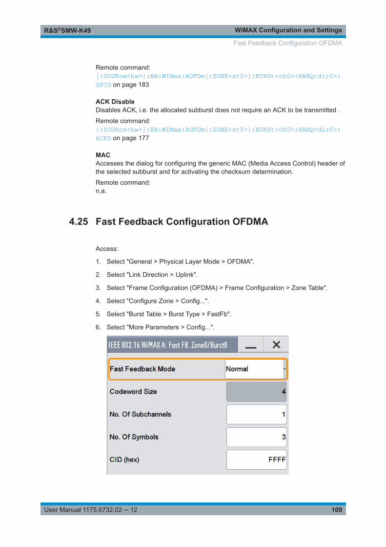
WiMAX Configuration and SettingsR&S®SMW-K49
109User Manual 1175.6732.02 ─ 12
Remote command: [:SOURce<hw>]:BB:WIMax:AOFDm[:ZONE<st0>]:BURSt<ch0>:HARQ<dir0>:SPID on page 183
ACK DisableDisables ACK, i.e. the allocated subburst does not require an ACK to be transmitted .
Remote command: [:SOURce<hw>]:BB:WIMax:AOFDm[:ZONE<st0>]:BURSt<ch0>:HARQ<dir0>:ACKD on page 177
MACAccesses the dialog for configuring the generic MAC (Media Access Control) header ofthe selected subburst and for activating the checksum determination.
Remote command: n.a.
4.25 Fast Feedback Configuration OFDMA
Access:
1. Select "General > Physical Layer Mode > OFDMA".
2. Select "Link Direction > Uplink".
3. Select "Frame Configuration (OFDMA) > Frame Configuration > Zone Table".
4. Select "Configure Zone > Config...".
5. Select "Burst Table > Burst Type > FastFb".
6. Select "More Parameters > Config...".
Fast Feedback Configuration OFDMA
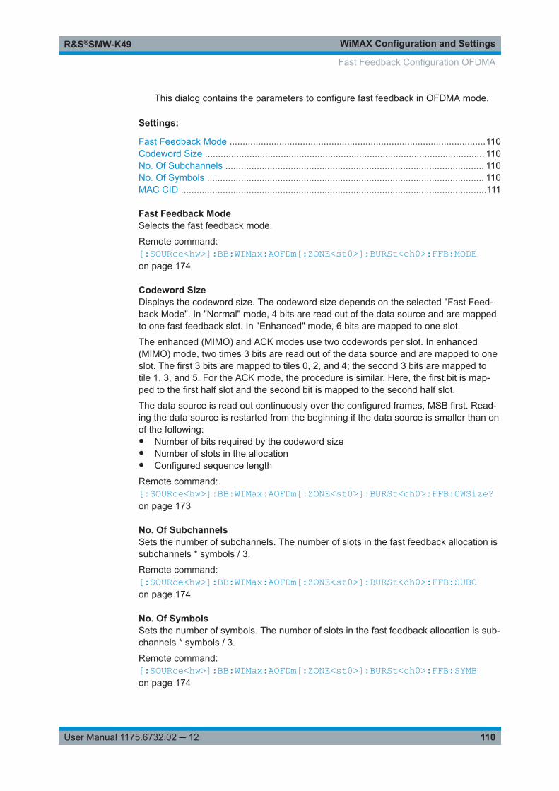
WiMAX Configuration and SettingsR&S®SMW-K49
110User Manual 1175.6732.02 ─ 12
This dialog contains the parameters to configure fast feedback in OFDMA mode.
Settings:
Fast Feedback Mode ..................................................................................................110Codeword Size ........................................................................................................... 110No. Of Subchannels ................................................................................................... 110No. Of Symbols .......................................................................................................... 110MAC CID .....................................................................................................................111
Fast Feedback ModeSelects the fast feedback mode.
Remote command: [:SOURce<hw>]:BB:WIMax:AOFDm[:ZONE<st0>]:BURSt<ch0>:FFB:MODEon page 174
Codeword SizeDisplays the codeword size. The codeword size depends on the selected "Fast Feed-back Mode". In "Normal" mode, 4 bits are read out of the data source and are mappedto one fast feedback slot. In "Enhanced" mode, 6 bits are mapped to one slot.
The enhanced (MIMO) and ACK modes use two codewords per slot. In enhanced(MIMO) mode, two times 3 bits are read out of the data source and are mapped to oneslot. The first 3 bits are mapped to tiles 0, 2, and 4; the second 3 bits are mapped totile 1, 3, and 5. For the ACK mode, the procedure is similar. Here, the first bit is map-ped to the first half slot and the second bit is mapped to the second half slot.
The data source is read out continuously over the configured frames, MSB first. Read-ing the data source is restarted from the beginning if the data source is smaller than onof the following:● Number of bits required by the codeword size● Number of slots in the allocation● Configured sequence length
Remote command: [:SOURce<hw>]:BB:WIMax:AOFDm[:ZONE<st0>]:BURSt<ch0>:FFB:CWSize?on page 173
No. Of SubchannelsSets the number of subchannels. The number of slots in the fast feedback allocation issubchannels * symbols / 3.
Remote command: [:SOURce<hw>]:BB:WIMax:AOFDm[:ZONE<st0>]:BURSt<ch0>:FFB:SUBCon page 174
No. Of SymbolsSets the number of symbols. The number of slots in the fast feedback allocation is sub-channels * symbols / 3.
Remote command: [:SOURce<hw>]:BB:WIMax:AOFDm[:ZONE<st0>]:BURSt<ch0>:FFB:SYMBon page 174
Fast Feedback Configuration OFDMA
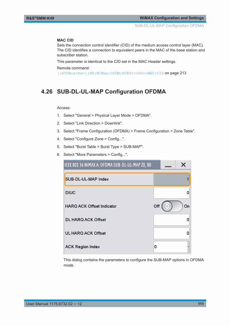
WiMAX Configuration and SettingsR&S®SMW-K49
111User Manual 1175.6732.02 ─ 12
MAC CIDSets the connection control identifier (CID) of the medium access control layer (MAC).The CID identifies a connection to equivalent peers in the MAC of the base station andsubscriber station.
This parameter is identical to the CID set in the MAC Header settings.
Remote command: [:SOURce<hw>]:BB:WIMax:OFDM:BURSt<ch0>:MAC:CID on page 213
4.26 SUB-DL-UL-MAP Configuration OFDMA
Access:
1. Select "General > Physical Layer Mode > OFDMA".
2. Select "Link Direction > Downlink".
3. Select "Frame Configuration (OFDMA) > Frame Configuration > Zone Table".
4. Select "Configure Zone > Config...".
5. Select "Burst Table > Burst Type > SUB-MAP".
6. Select "More Parameters > Config...".
This dialog contains the parameters to configure the SUB-MAP options in OFDMAmode.
SUB-DL-UL-MAP Configuration OFDMA
WiMAX Configuration and SettingsR&S®SMW-K49
112User Manual 1175.6732.02 ─ 12
Settings:
SUB-DL-UL-MAP Index ..............................................................................................112DIUC OFDMA .............................................................................................................112HARQ ACK Offset Indicator ....................................................................................... 112DL HARQ ACK Offset .................................................................................................112
└ UL HARQ ACK Offset .................................................................................. 112ACK Region Index ......................................................................................................112
SUB-DL-UL-MAP IndexDisplays the number of the SUB-DL-UL-MAP message.
Altogether up to three SUB-DL-UL-MAP messages can be enabled for all zones. The"SUB-DL-UL-MAP Index" is a consecutive number that is assigned for each configuredSUB-DL-UL-MAP message.
Remote command: [:SOURce<hw>]:BB:WIMax:AOFDm[:ZONE<st0>]:BURSt<ch0>:DLUL:MPIX?on page 173
DIUC OFDMASets the specific DIUC.
In DL-MAP mode "Auto", the DIUC of each burst is included in the DL-MAP.
Remote command: [:SOURce<hw>]:BB:WIMax:AOFDm[:ZONE<st0>]:BURSt<ch0>:DIUCon page 171
HARQ ACK Offset IndicatorEnables/disables the inclusion of HARQ offsets.
Remote command: [:SOURce<hw>]:BB:WIMax:AOFDm[:ZONE<st0>]:BURSt<ch0>:DLUL:HARQ:ACKoffset:INDicator on page 172
DL HARQ ACK OffsetSets the ACK channel that corresponds to the first HARQ-enabled DL burst specifiedin this map message.
Remote command: [:SOURce<hw>]:BB:WIMax:AOFDm[:ZONE<st0>]:BURSt<ch0>:DLUL:HARQ:ACKoffset:DL on page 172
UL HARQ ACK Offset ← DL HARQ ACK OffsetSets the ACK bit index in the DL HARQ ACK that corresponds to the first HARQ-enabled UL burst specified in this map message.
Remote command: [:SOURce<hw>]:BB:WIMax:AOFDm[:ZONE<st0>]:BURSt<ch0>:DLUL:HARQ:ACKoffset:UL on page 172
ACK Region IndexSelects whether ACK region 0 or 1 is used.
SUB-DL-UL-MAP Configuration OFDMA
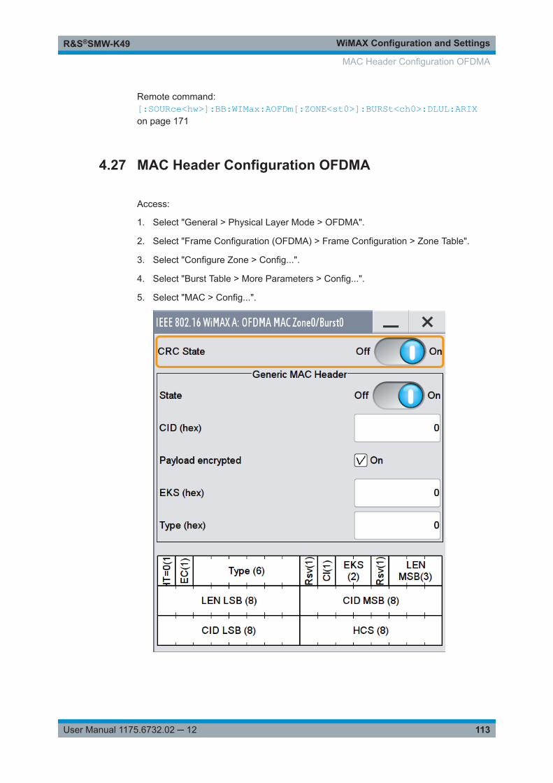
WiMAX Configuration and SettingsR&S®SMW-K49
113User Manual 1175.6732.02 ─ 12
Remote command: [:SOURce<hw>]:BB:WIMax:AOFDm[:ZONE<st0>]:BURSt<ch0>:DLUL:ARIXon page 171
4.27 MAC Header Configuration OFDMA
Access:
1. Select "General > Physical Layer Mode > OFDMA".
2. Select "Frame Configuration (OFDMA) > Frame Configuration > Zone Table".
3. Select "Configure Zone > Config...".
4. Select "Burst Table > More Parameters > Config...".
5. Select "MAC > Config...".
MAC Header Configuration OFDMA
WiMAX Configuration and SettingsR&S®SMW-K49
114User Manual 1175.6732.02 ─ 12
This dialog contains the settings for a generic MAC header of the correspondingzone and burst. The MAC header is placed at the beginning of the burst when acti-vated.
In addition CRC (Cyclic Redundancy Check) can be activated, which is added at theend of the burst. It covers MAC header and all data.
Settings:
CRC State .................................................................................................................. 114MAC Header State ..................................................................................................... 114MAC CID .................................................................................................................... 114Payload encrypted ......................................................................................................114EKS ............................................................................................................................ 115Mac Type ....................................................................................................................115
CRC StateActivates/deactivates the checksum determination. The state of the CRC can be setindependently of the state of MAC header generation.
Remote command: [:SOURce<hw>]:BB:WIMax:AOFDm[:ZONE<st0>]:BURSt<ch0>:MAC:CRC:STATe on page 184[:SOURce<hw>]:BB:WIMax:AOFDm[:ZONE<st0>]:BURSt<ch0>:HARQ<dir0>:MAC:CRC:STATe on page 180
MAC Header StateActivates the generation of the generic MAC header.
Remote command: [:SOURce<hw>]:BB:WIMax:AOFDm[:ZONE<st0>]:BURSt<ch0>:MAC:STATeon page 185[:SOURce<hw>]:BB:WIMax:AOFDm[:ZONE<st0>]:BURSt<ch0>:HARQ<dir0>:MAC:STATe on page 181
MAC CIDThe command sets the CID (connection control identifier) of the medium access con-trol layer (MAC). The CID identifies a connection to equivalent peers in the MAC of thebase station and subscriber station.
This parameter is identical to the CID set in the MAC Header settings.
Remote command: [:SOURce<hw>]:BB:WIMax:AOFDm[:ZONE<st0>]:BURSt<ch0>:MAC:CIDon page 183[:SOURce<hw>]:BB:WIMax:AOFDm[:ZONE<st0>]:BURSt<ch0>:HARQ<dir0>:MAC:CID on page 180
Payload encryptedActivates/deactivates payload encryption.
If activated, the EC (Encryption Control) field is set to 1 and the EKS ("Encryption KeySequence") field can be set.
MAC Header Configuration OFDMA
WiMAX Configuration and SettingsR&S®SMW-K49
115User Manual 1175.6732.02 ─ 12
Remote command: [:SOURce<hw>]:BB:WIMax:AOFDm[:ZONE<st0>]:BURSt<ch0>:MAC:ENCRypted:STATe on page 184[:SOURce<hw>]:BB:WIMax:AOFDm[:ZONE<st0>]:BURSt<ch0>:HARQ<dir0>:MAC:ENCRypted:STATe on page 181
EKSSets the EKS ("Encryption Key Sequence") value in the MAC header. The payloadencryption itself is not performed by the signal generator.
Remote command: [:SOURce<hw>]:BB:WIMax:AOFDm[:ZONE<st0>]:BURSt<ch0>:MAC:EKSon page 184[:SOURce<hw>]:BB:WIMax:AOFDm[:ZONE<st0>]:BURSt<ch0>:HARQ<dir0>:MAC:EKS on page 180
Mac TypeSpecifies the MAC type.
The value of the 6-bit type field is set which indicates the payload type, including thepresence of subheaders.
Remote command: [:SOURce<hw>]:BB:WIMax:AOFDm[:ZONE<st0>]:BURSt<ch0>:MAC:TYPEon page 185[:SOURce<hw>]:BB:WIMax:AOFDm[:ZONE<st0>]:BURSt<ch0>:HARQ<dir0>:MAC:TYPE on page 181
4.28 PDU MAC Configuration OFDMA
Access:
1. Select "General > Physical Layer Mode > OFDMA".
2. Select "Frame Configuration (OFDMA) > Frame Configuration > Zone Table".
3. Select "Configure Zone > Config...".
4. Select "Burst Table > Burst Type > Data".
5. Select "More Parameters > Config...".
6. Select "Multiple PDUS > On > MAC > Config...".
PDU MAC Configuration OFDMA
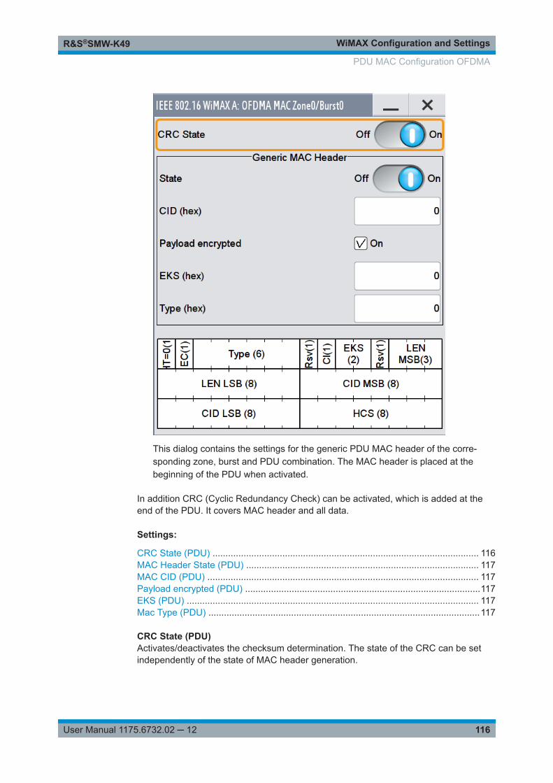
WiMAX Configuration and SettingsR&S®SMW-K49
116User Manual 1175.6732.02 ─ 12
This dialog contains the settings for the generic PDU MAC header of the corre-sponding zone, burst and PDU combination. The MAC header is placed at thebeginning of the PDU when activated.
In addition CRC (Cyclic Redundancy Check) can be activated, which is added at theend of the PDU. It covers MAC header and all data.
Settings:
CRC State (PDU) ....................................................................................................... 116MAC Header State (PDU) .......................................................................................... 117MAC CID (PDU) ......................................................................................................... 117Payload encrypted (PDU) ...........................................................................................117EKS (PDU) ................................................................................................................. 117Mac Type (PDU) .........................................................................................................117
CRC State (PDU)Activates/deactivates the checksum determination. The state of the CRC can be setindependently of the state of MAC header generation.
PDU MAC Configuration OFDMA
WiMAX Configuration and SettingsR&S®SMW-K49
117User Manual 1175.6732.02 ─ 12
Remote command: [:SOURce<hw>]:BB:WIMax:AOFDm[:ZONE<st0>]:BURSt<ch0>:PDU<dir0>:MAC:CRC:STATe on page 189
MAC Header State (PDU)Activates the generation of the generic MAC header.
Remote command: [:SOURce<hw>]:BB:WIMax:AOFDm[:ZONE<st0>]:BURSt<ch0>:PDU<dir0>:MAC:STATe on page 190
MAC CID (PDU)The command sets the CID (Connection Control Identifier) of the medium access con-trol layer (MAC). The CID identifies a connection to equivalent peers in the MAC of thebase station and subscriber station.
Remote command: [:SOURce<hw>]:BB:WIMax:AOFDm[:ZONE<st0>]:BURSt<ch0>:PDU<dir0>[:MAC]:CID on page 190
Payload encrypted (PDU)Activates/deactivates payload encryption.
If activated, the EC (Encryption Control) field is set to 1 and the EKS ("Encryption KeySequence) "field can be set.
Remote command: [:SOURce<hw>]:BB:WIMax:AOFDm[:ZONE<st0>]:BURSt<ch0>:PDU<dir0>:MAC:ENCRypted:STATe on page 189
EKS (PDU)Sets the EKS ("Encryption Key Sequence") value in the MAC header. The payloadencryption itself is not performed by the signal generator.
Remote command: [:SOURce<hw>]:BB:WIMax:AOFDm[:ZONE<st0>]:BURSt<ch0>:PDU<dir0>:MAC:EKS on page 189
Mac Type (PDU)Specifies the MAC type.
The value of the 6-bit type field is set which indicates the payload type, including thepresence of subheaders.
Remote command: [:SOURce<hw>]:BB:WIMax:AOFDm[:ZONE<st0>]:BURSt<ch0>:PDU<dir0>:MAC:TYPE on page 190
PDU MAC Configuration OFDMA
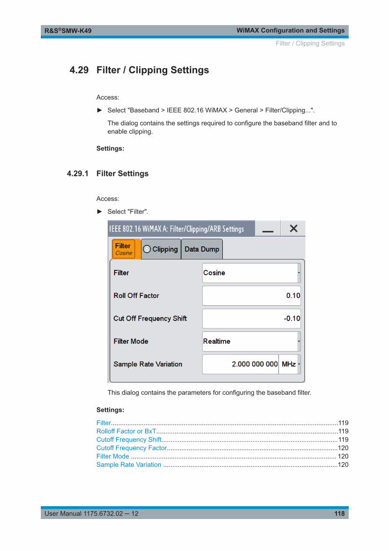
WiMAX Configuration and SettingsR&S®SMW-K49
118User Manual 1175.6732.02 ─ 12
4.29 Filter / Clipping Settings
Access:
► Select "Baseband > IEEE 802.16 WiMAX > General > Filter/Clipping...".
The dialog contains the settings required to configure the baseband filter and toenable clipping.
Settings:
4.29.1 Filter Settings
Access:
► Select "Filter".
This dialog contains the parameters for configuring the baseband filter.
Settings:
Filter.............................................................................................................................119Rolloff Factor or BxT....................................................................................................119Cutoff Frequency Shift.................................................................................................119Cutoff Frequency Factor..............................................................................................120Filter Mode ................................................................................................................. 120Sample Rate Variation ................................................................................................120
Filter / Clipping Settings
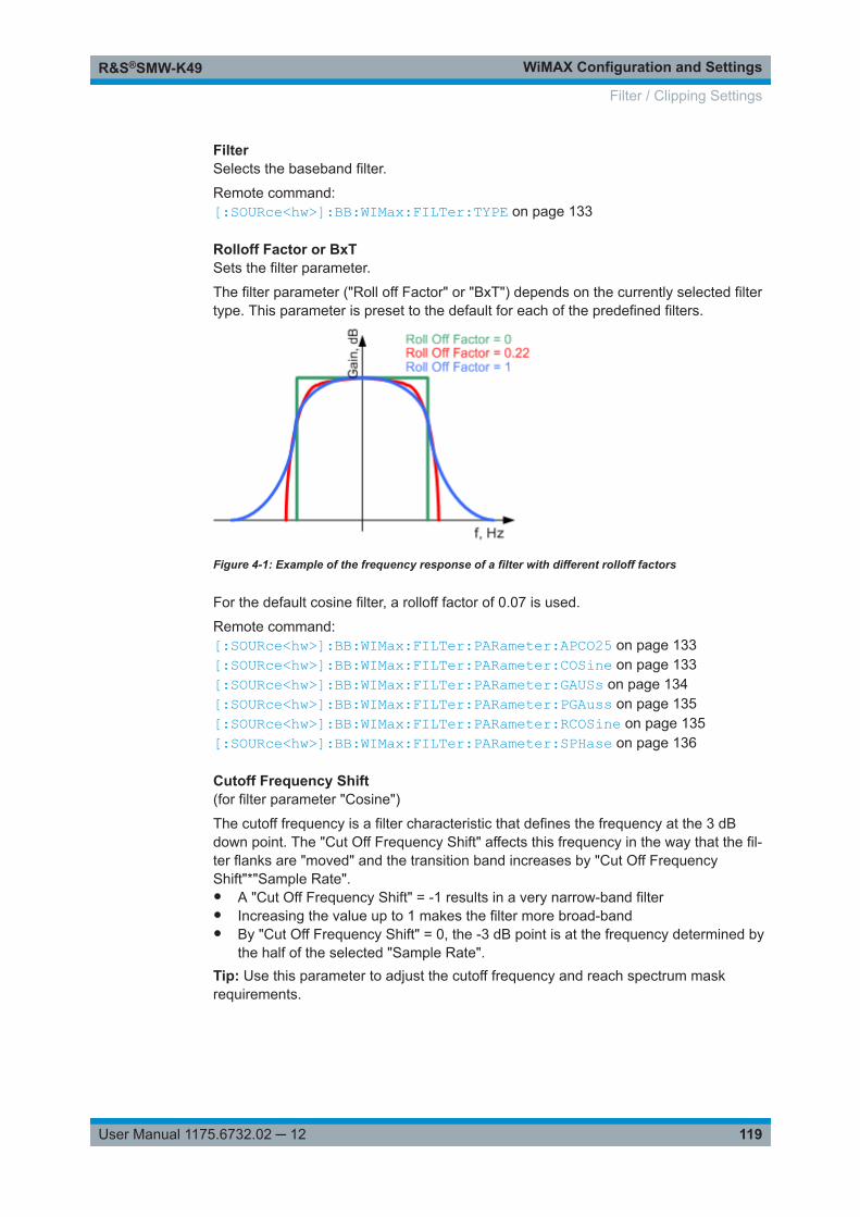
WiMAX Configuration and SettingsR&S®SMW-K49
119User Manual 1175.6732.02 ─ 12
FilterSelects the baseband filter.
Remote command: [:SOURce<hw>]:BB:WIMax:FILTer:TYPE on page 133
Rolloff Factor or BxTSets the filter parameter.
The filter parameter ("Roll off Factor" or "BxT") depends on the currently selected filtertype. This parameter is preset to the default for each of the predefined filters.
Figure 4-1: Example of the frequency response of a filter with different rolloff factors
For the default cosine filter, a rolloff factor of 0.07 is used.
Remote command: [:SOURce<hw>]:BB:WIMax:FILTer:PARameter:APCO25 on page 133[:SOURce<hw>]:BB:WIMax:FILTer:PARameter:COSine on page 133[:SOURce<hw>]:BB:WIMax:FILTer:PARameter:GAUSs on page 134[:SOURce<hw>]:BB:WIMax:FILTer:PARameter:PGAuss on page 135[:SOURce<hw>]:BB:WIMax:FILTer:PARameter:RCOSine on page 135[:SOURce<hw>]:BB:WIMax:FILTer:PARameter:SPHase on page 136
Cutoff Frequency Shift(for filter parameter "Cosine")
The cutoff frequency is a filter characteristic that defines the frequency at the 3 dBdown point. The "Cut Off Frequency Shift" affects this frequency in the way that the fil-ter flanks are "moved" and the transition band increases by "Cut Off FrequencyShift"*"Sample Rate".● A "Cut Off Frequency Shift" = -1 results in a very narrow-band filter● Increasing the value up to 1 makes the filter more broad-band● By "Cut Off Frequency Shift" = 0, the -3 dB point is at the frequency determined by
the half of the selected "Sample Rate".Tip: Use this parameter to adjust the cutoff frequency and reach spectrum maskrequirements.
Filter / Clipping Settings
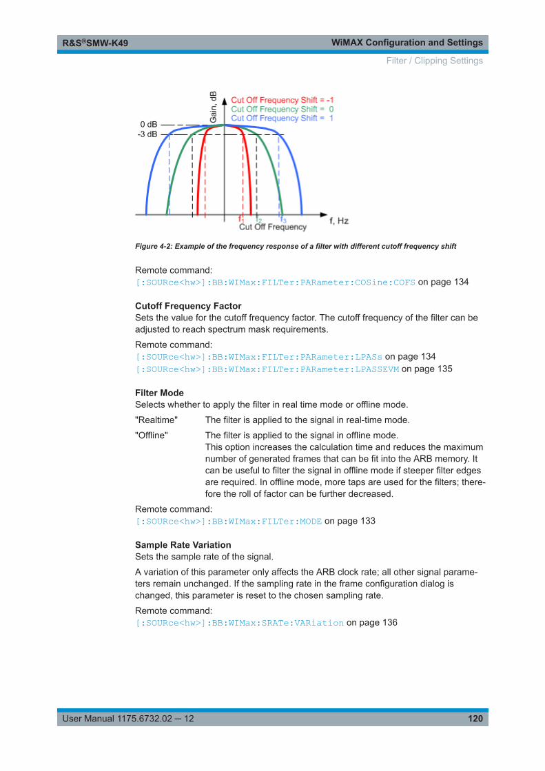
WiMAX Configuration and SettingsR&S®SMW-K49
120User Manual 1175.6732.02 ─ 12
Figure 4-2: Example of the frequency response of a filter with different cutoff frequency shift
Remote command: [:SOURce<hw>]:BB:WIMax:FILTer:PARameter:COSine:COFS on page 134
Cutoff Frequency FactorSets the value for the cutoff frequency factor. The cutoff frequency of the filter can beadjusted to reach spectrum mask requirements.
Remote command: [:SOURce<hw>]:BB:WIMax:FILTer:PARameter:LPASs on page 134[:SOURce<hw>]:BB:WIMax:FILTer:PARameter:LPASSEVM on page 135
Filter ModeSelects whether to apply the filter in real time mode or offline mode.
"Realtime" The filter is applied to the signal in real-time mode.
"Offline" The filter is applied to the signal in offline mode.This option increases the calculation time and reduces the maximumnumber of generated frames that can be fit into the ARB memory. Itcan be useful to filter the signal in offline mode if steeper filter edgesare required. In offline mode, more taps are used for the filters; there-fore the roll of factor can be further decreased.
Remote command: [:SOURce<hw>]:BB:WIMax:FILTer:MODE on page 133
Sample Rate VariationSets the sample rate of the signal.
A variation of this parameter only affects the ARB clock rate; all other signal parame-ters remain unchanged. If the sampling rate in the frame configuration dialog ischanged, this parameter is reset to the chosen sampling rate.
Remote command: [:SOURce<hw>]:BB:WIMax:SRATe:VARiation on page 136
Filter / Clipping Settings
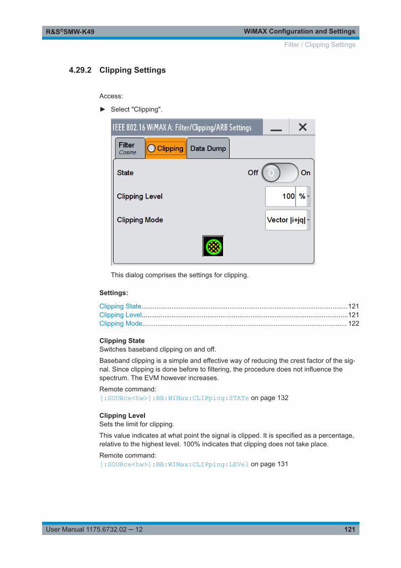
WiMAX Configuration and SettingsR&S®SMW-K49
121User Manual 1175.6732.02 ─ 12
4.29.2 Clipping Settings
Access:
► Select "Clipping".
This dialog comprises the settings for clipping.
Settings:
Clipping State..............................................................................................................121Clipping Level..............................................................................................................121Clipping Mode............................................................................................................. 122
Clipping StateSwitches baseband clipping on and off.
Baseband clipping is a simple and effective way of reducing the crest factor of the sig-nal. Since clipping is done before to filtering, the procedure does not influence thespectrum. The EVM however increases.
Remote command: [:SOURce<hw>]:BB:WIMax:CLIPping:STATe on page 132
Clipping LevelSets the limit for clipping.
This value indicates at what point the signal is clipped. It is specified as a percentage,relative to the highest level. 100% indicates that clipping does not take place.
Remote command: [:SOURce<hw>]:BB:WIMax:CLIPping:LEVel on page 131
Filter / Clipping Settings
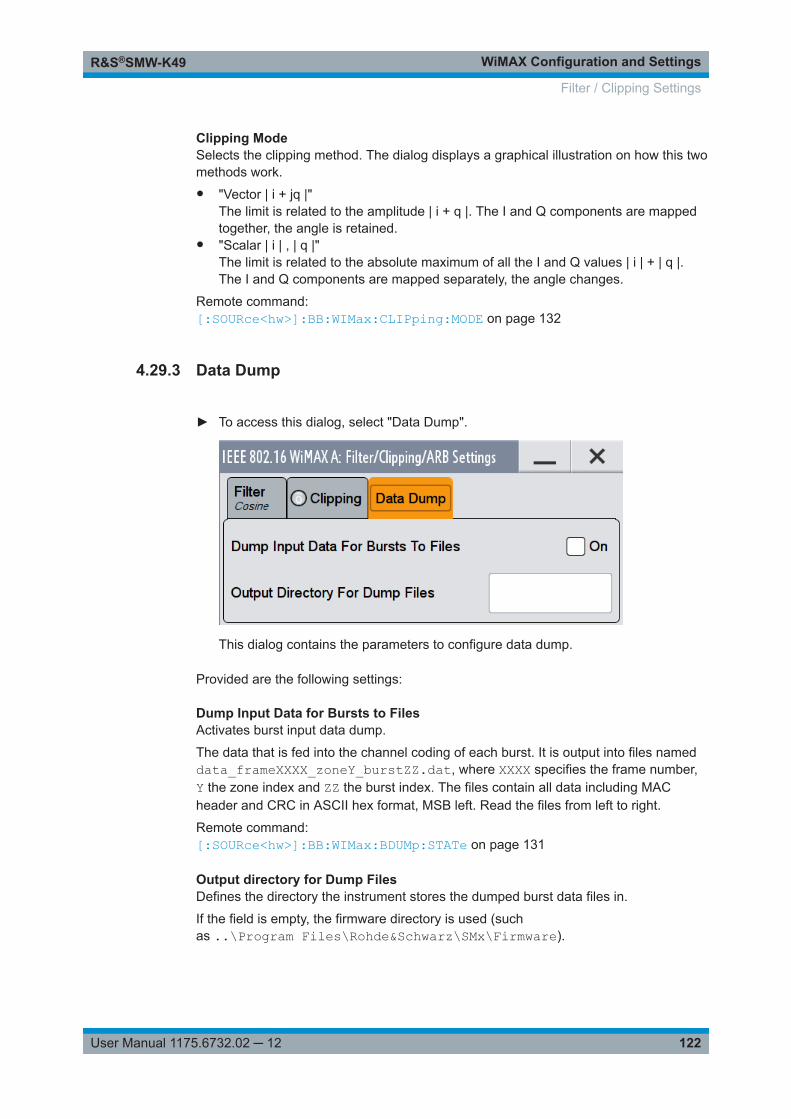
WiMAX Configuration and SettingsR&S®SMW-K49
122User Manual 1175.6732.02 ─ 12
Clipping ModeSelects the clipping method. The dialog displays a graphical illustration on how this twomethods work.● "Vector | i + jq |"
The limit is related to the amplitude | i + q |. The I and Q components are mappedtogether, the angle is retained.
● "Scalar | i | , | q |"The limit is related to the absolute maximum of all the I and Q values | i | + | q |.The I and Q components are mapped separately, the angle changes.
Remote command: [:SOURce<hw>]:BB:WIMax:CLIPping:MODE on page 132
4.29.3 Data Dump
► To access this dialog, select "Data Dump".
This dialog contains the parameters to configure data dump.
Provided are the following settings:
Dump Input Data for Bursts to FilesActivates burst input data dump.
The data that is fed into the channel coding of each burst. It is output into files nameddata_frameXXXX_zoneY_burstZZ.dat, where XXXX specifies the frame number,Y the zone index and ZZ the burst index. The files contain all data including MACheader and CRC in ASCII hex format, MSB left. Read the files from left to right.
Remote command: [:SOURce<hw>]:BB:WIMax:BDUMp:STATe on page 131
Output directory for Dump FilesDefines the directory the instrument stores the dumped burst data files in.
If the field is empty, the firmware directory is used (suchas ..\Program Files\Rohde&Schwarz\SMx\Firmware).
Filter / Clipping Settings
WiMAX Configuration and SettingsR&S®SMW-K49
123User Manual 1175.6732.02 ─ 12
Remote command: [:SOURce<hw>]:BB:WIMax:BDUMp:DIRectory on page 131
Filter / Clipping Settings
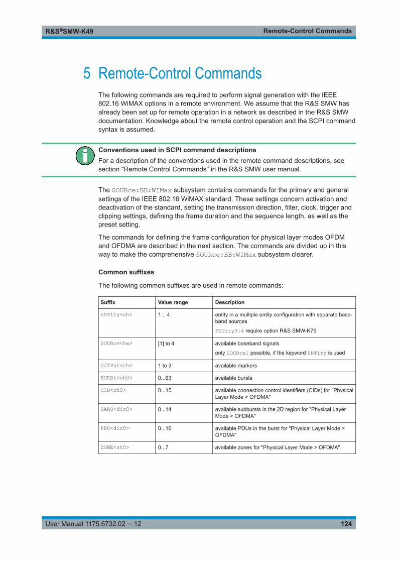
Remote-Control CommandsR&S®SMW-K49
124User Manual 1175.6732.02 ─ 12
5 Remote-Control CommandsThe following commands are required to perform signal generation with the IEEE802.16 WiMAX options in a remote environment. We assume that the R&S SMW hasalready been set up for remote operation in a network as described in the R&S SMWdocumentation. Knowledge about the remote control operation and the SCPI commandsyntax is assumed.
Conventions used in SCPI command descriptionsFor a description of the conventions used in the remote command descriptions, seesection "Remote Control Commands" in the R&S SMW user manual.
The SOURce:BB:WIMax subsystem contains commands for the primary and generalsettings of the IEEE 802.16 WiMAX standard. These settings concern activation anddeactivation of the standard, setting the transmission direction, filter, clock, trigger andclipping settings, defining the frame duration and the sequence length, as well as thepreset setting.
The commands for defining the frame configuration for physical layer modes OFDMand OFDMA are described in the next section. The commands are divided up in thisway to make the comprehensive SOURce:BB:WIMax subsystem clearer.
Common suffixes
The following common suffixes are used in remote commands:
Suffix Value range Description
ENTity<ch> 1 .. 4 entity in a multiple entity configuration with separate base-band sources
ENTity3|4 require option R&S SMW-K76
SOURce<hw> [1] to 4 available baseband signals
only SOURce1 possible, if the keyword ENTity is used
OUTPut<ch> 1 to 3 available markers
BURSt<ch0> 0...63 available bursts
CID<ch0> 0...15 available connection control identifiers (CIDs) for "PhysicalLayer Mode > OFDMA"
HARQ<dir0> 0...14 available subbursts in the 2D region for "Physical LayerMode > OFDMA"
PDU<dir0> 0...16 available PDUs in the burst for "Physical Layer Mode >OFDMA"
ZONE<st0> 0...7 available zones for "Physical Layer Mode > OFDMA"
Remote-Control CommandsR&S®SMW-K49
125User Manual 1175.6732.02 ─ 12
Using SCPI command aliases for advanced mode with multiple entitiesYou can address multiple entities configurations by using the SCPI commands startingwith the keyword SOURce or the alias commands starting with the keyword ENTity.
Note that the meaning of the keyword SOURce<hw> changes in the second case.
For details, see section "SCPI Command Aliases for Advanced Mode with MultipleEntities" in the R&S SMW user manual.
The following commands specific to the IEEE 802.16 WiMAX standard are describedhere:
5.1 General Commands.................................................................................................. 125
5.2 Filter/Clipping Settings.............................................................................................131
5.3 Trigger Settings.........................................................................................................136
5.4 Marker Settings......................................................................................................... 141
5.5 Clock Settings........................................................................................................... 143
5.6 OFDMA Physical Layer Settings..............................................................................144
5.7 OFDM Physical Layer Settings................................................................................ 207
5.1 General Commands
[:SOURce<hw>]:BB:WIMax:DUPLexing........................................................................... 125[:SOURce<hw>]:BB:WIMax:FRAMe:BURSt:DELay........................................................... 126[:SOURce<hw>]:BB:WIMax:FRAMe:TIME........................................................................ 126[:SOURce<hw>]:BB:WIMax:FRAMe:TIME:USER.............................................................. 127[:SOURce<hw>]:BB:WIMax:LINK.....................................................................................127[:SOURce<hw>]:BB:WIMax:MODE.................................................................................. 127[:SOURce<hw>]:BB:WIMax:PRESet................................................................................ 127[:SOURce<hw>]:BB:WIMax:SETTing:CATalog?.................................................................128[:SOURce<hw>]:BB:WIMax:SETTing:DELete....................................................................128[:SOURce<hw>]:BB:WIMax:SETTing:LOAD......................................................................128[:SOURce<hw>]:BB:WIMax:SETTing:STORe....................................................................129[:SOURce<hw>]:BB:WIMax:SLENgth...............................................................................129[:SOURce<hw>]:BB:WIMax:STATe...................................................................................129[:SOURce<hw>]:BB:WIMax:SUBFrame:TIME................................................................... 130[:SOURce<hw>]:BB:WIMax:WAVeform:CREate................................................................ 130[:SOURce<hw>][:BB]:WIMax:SVERsion........................................................................... 130
[:SOURce<hw>]:BB:WIMax:DUPLexing <Duplexing>
Selects the duplexing. The duplexing mode determines how the uplink and downlinksignal are separated.
General Commands
Remote-Control CommandsR&S®SMW-K49
126User Manual 1175.6732.02 ─ 12
Parameters:<Duplexing> TDD | FDD
*RST: TDD
Example: BB:WIM:DUPL FDDselects frequency division duplexing.
Manual operation: See "Duplexing" on page 18
[:SOURce<hw>]:BB:WIMax:FRAMe:BURSt:DELay <Delay>
The command sets the delay for the first uplink burst.
The command is only available for physical layer mode OFDM in uplink and for FDDduplexing.
Parameters:<Delay> float
Range: 0 s to 1E6 s>Increment: 1 µs*RST: 0 s
Example: BB:WIM:MODE OFDMselects physical layer mode OFDM.BB:WIM:LINK UPselects transmission direction uplink.BB:WIM:DUP FDDselects FDD duplexing.BB:WIM:FRAM:BURS:DEL 0.004selects a delay of 4 ms for the first burst.
Manual operation: See " Initial Delay of Burst 1 " on page 29
[:SOURce<hw>]:BB:WIMax:FRAMe:TIME <Time>
The command selects the frame duration. Only distinct values are allowed in the stan-dard. For test reasons, continuous generation or generation for a freely selectableduration (USER) are available. The user duration is set with commandSOUR:BB:WIM:FRAM:TIME:USER. In continuous mode, the frame duration equals thesum of the burst durations.
Parameters:<Time> MS2 | MS2D5 | MS4 | MS5 | MS8 | MS10 | MS12D5 | MS20 |
CONTinuous | USER*RST: MS10
Example: BB:WIM:FRAM:TIME MS12D5selects a frame length of 12.5 ms.
Manual operation: See " Frame Duration " on page 29
General Commands
Remote-Control CommandsR&S®SMW-K49
127User Manual 1175.6732.02 ─ 12
[:SOURce<hw>]:BB:WIMax:FRAMe:TIME:USER <User>
The command sets the frame duration to a freely selectable value.
Parameters:<User> float
Range: 0 s to 0.1 sIncrement: 1E-6 s*RST: 0.01s
Manual operation: See " User Frame Duration " on page 29
[:SOURce<hw>]:BB:WIMax:LINK <Link>
The command defines the transmission direction. The signal either corresponds to thatof a base station (FORWard | DOWN) or that of a subscriber station (REVerse | UP).
Parameters:<Link> FORWard | REVerse | UP | DOWN
*RST: FORWard
Example: BB:WIM:LINK DOWNthe transmission direction selected is base station to subscriberstation. The signal corresponds to that of a base station.
Manual operation: See "Link Direction" on page 19
[:SOURce<hw>]:BB:WIMax:MODE <Mode>
Selects the Physical Layer Mode.
Parameters:<Mode> OFDM | AOFDm | WIBRo | AAI
AOFDmOrthogonal Frequency Division Multiple Access (OFDMA)*RST: OFDM
Example: BB:WIM:MODE OFDMSelects physical layer mode OFDM.
Manual operation: See "Physical Layer Mode" on page 17
[:SOURce<hw>]:BB:WIMax:PRESet
Sets the parameters of the digital standard to their default values (*RST values speci-fied for the commands).
Not affected is the state set with the command SOURce<hw>:BB:WIMax:STATe.
Example: SOURce1:BB:WIMax:PRESetUsage: Event
General Commands
Remote-Control CommandsR&S®SMW-K49
128User Manual 1175.6732.02 ─ 12
Manual operation: See "Set to Default" on page 15
[:SOURce<hw>]:BB:WIMax:SETTing:CATalog?
This command reads out the files with IEEE 802.16 settings in the default directory.The default directory is set using command MMEM:CDIRectory. Only files with the fileextension *.wimax are listed.
Return values: <Catalog> string
Example: MMEM:CDIR "/var/user/temp/wimax"Sets the default directory to /var/user/temp/wimax.BB:WIM:SETT:CAT?Reads out all the files with IEEE 802.16 settings in the defaultdirectory.Response: "ofdm","fbpsk"The files ofdm and fbpsk are available.
Usage: Query only
Manual operation: See "Save/Recall" on page 17
[:SOURce<hw>]:BB:WIMax:SETTing:DELete <Filename>
This command deletes the selected file with IEEE 802.16 WiMAX settings. The direc-tory is set using command MMEM:CDIRectory. A path can also be specified, in whichcase the files in the specified directory are read. The file extension can be omitted.Only files with the file extension *.wimax are deleted.
Setting parameters: <Filename> string
Example: BB:WIM:SETT:DEL 'ofdm'Deletes file ofdm.
Usage: Setting only
Manual operation: See "Save/Recall" on page 17
[:SOURce<hw>]:BB:WIMax:SETTing:LOAD <Filename>
This command loads the selected file with IEEE 802.16 WiMAX settings. The directoryis set using command MMEM:CDIRectory. A path can also be specified, in whichcase the files in the specified directory are read. The file extension can be omitted.Only files with the file extension *.wimax are loaded.
Setting parameters: <Filename> string
Example: BB:WIM:SETT:LOAD 'ofdm'Loads file ofdm.
General Commands
Remote-Control CommandsR&S®SMW-K49
129User Manual 1175.6732.02 ─ 12
Usage: Setting only
Manual operation: See "Save/Recall" on page 17
[:SOURce<hw>]:BB:WIMax:SETTing:STORe <Filename>
This command stores the current IEE 802.16 WIMAX settings into theselected file. The directory is set using command MMEM:CDIRec-tory. A path can also be specified, in which case the files in the specified directory areread. Enter only the file name. IEE 802.16 WIMAX settings are stored as files with thespecific file extensions *.wimax.
Setting parameters: <Filename> string
Example: BB:WIM:SETT:STOR 'ofdm_tdd'Stores the current settings into file ofdm_tdd.
Usage: Setting only
Manual operation: See "Save/Recall" on page 17
[:SOURce<hw>]:BB:WIMax:SLENgth <SLength>
Sets the number of frames. The maximum number of frames depends on the samplingrate, the set frame length (2 x sampling rate x frame length / commandBB:WIM:FRAM:TIM) and the supplied ARB memory size.
Parameters:<SLength> integer
Range: 1 to MAX*RST: 1
Example: BB:WIM:SLEN 4selects the generation of 4 frames.
Manual operation: See " Sequence Length " on page 29
[:SOURce<hw>]:BB:WIMax:STATe <State>
Activates the standard and deactivates all the other digital standards and digital modu-lation modes in the same path.
Parameters:<State> 0 | 1 | OFF | ON
*RST: 0
Example: SOURce1:BB:WIMax:STATe ONManual operation: See "State" on page 15
General Commands
Remote-Control CommandsR&S®SMW-K49
130User Manual 1175.6732.02 ─ 12
[:SOURce<hw>]:BB:WIMax:SUBFrame:TIME <Time>
The command set the duration of the downlink subframe.
The command is only available for uplink direction and when TDD is selected (in caseof two-path instruments, on the same path.
Parameters:<Time> float
Range: 0 ms to 20 msIncrement: 0.001ms*RST: 0 ms
Example: BB:WIM:LINK UPselects uplink transmission.BB:WIM:DUPL TDDselects time division duplexing.BB:WIM:SUBF:TIME 2mssets a subframe duration of 2 ms.
Manual operation: See " Downlink Subframe Duration " on page 29
[:SOURce<hw>]:BB:WIMax:WAVeform:CREate <Filename>
This command creates a waveform using the current settings of the "WiMAX" menu.The file name is entered with the command. The file is stored with the predefined fileextension *.wv. The file name and the directory it is stored in are user-definable.
Setting parameters: <Filename> string
Example: MMEM:CDIR "/var/user/temp/waveform"sets the default directory to /var/user/temp/waveform.BB:WIM:WAV:CRE "wimax_1"creates the waveform file wimax_1.wv in the default directory.
Usage: Setting only
Manual operation: See "Generate Waveform File…" on page 17
[:SOURce<hw>][:BB]:WIMax:SVERsion <SVersion>
Selects the version of the standard to use.
Parameters:<SVersion> VC1 | VC2D4 | VC3
*RST: VC1
Manual operation: See "Version" on page 18
General Commands
Remote-Control CommandsR&S®SMW-K49
131User Manual 1175.6732.02 ─ 12
5.2 Filter/Clipping Settings
[:SOURce<hw>]:BB:WIMax:BDUMp:DIRectory................................................................. 131[:SOURce<hw>]:BB:WIMax:BDUMp:STATe...................................................................... 131[:SOURce<hw>]:BB:WIMax:CLIPping:LEVel..................................................................... 131[:SOURce<hw>]:BB:WIMax:CLIPping:MODE....................................................................132[:SOURce<hw>]:BB:WIMax:CLIPping:STATe.................................................................... 132[:SOURce<hw>]:BB:WIMax:FILTer:TYPE......................................................................... 133[:SOURce<hw>]:BB:WIMax:FILTer:MODE........................................................................ 133[:SOURce<hw>]:BB:WIMax:FILTer:PARameter:APCO25....................................................133[:SOURce<hw>]:BB:WIMax:FILTer:PARameter:COSine..................................................... 133[:SOURce<hw>]:BB:WIMax:FILTer:PARameter:COSine:COFS........................................... 134[:SOURce<hw>]:BB:WIMax:FILTer:PARameter:GAUSs......................................................134[:SOURce<hw>]:BB:WIMax:FILTer:PARameter:LPASs.......................................................134[:SOURce<hw>]:BB:WIMax:FILTer:PARameter:LPASSEVM............................................... 135[:SOURce<hw>]:BB:WIMax:FILTer:PARameter:PGAuss.....................................................135[:SOURce<hw>]:BB:WIMax:FILTer:PARameter:RCOSine...................................................135[:SOURce<hw>]:BB:WIMax:FILTer:PARameter:SPHase.....................................................136[:SOURce<hw>]:BB:WIMax:SRATe:VARiation...................................................................136
[:SOURce<hw>]:BB:WIMax:BDUMp:DIRectory <Directory>
Defines the directory the dumped burst date files are to be stored in.
If no directory is specified, the dumped files are stored in the firmware directory.
Parameters:<Directory> string
Example: see [:SOURce<hw>]:BB:WIMax:BDUMp:STATe on page 131
Manual operation: See " Output directory for Dump Files " on page 122
[:SOURce<hw>]:BB:WIMax:BDUMp:STATe <State>
Activates burst input data dump.
Parameters:<State> 0 | 1 | OFF | ON
*RST: 0
Example: SOURce1:BB:WIMax:BDUMp:DIRirectory"/var/user/temp/dump"sets the directory for OFDMA burst input dump.SOURce1:BB:WIMax:BDUMp:STATe ONactivates burst input data dump.
Manual operation: See " Dump Input Data for Bursts to Files " on page 122
[:SOURce<hw>]:BB:WIMax:CLIPping:LEVel <Level>
Sets the limit for level clipping.
Filter/Clipping Settings
Remote-Control CommandsR&S®SMW-K49
132User Manual 1175.6732.02 ─ 12
Parameters:<Level> integer
Range: 1 to 100*RST: 100
Example: BB:WIM:CLIP:LEV 80PCTsets the limit for level clipping to 80% of the maximum level.BB:WIM:CLIP:STAT ONactivates level clipping.
Manual operation: See "Clipping Level" on page 121
[:SOURce<hw>]:BB:WIMax:CLIPping:MODE <Mode>
The command sets the method for level clipping (Clipping).
Parameters:<Mode> VECTor | SCALar
VECTorThe reference level is the amplitude | i+jq |.SCALarThe reference level is the absolute maximum of the I and Q val-ues.*RST: VECTor
Example: BB:WIM:CLIP:MODE SCALselects the absolute maximum of all the I and Q values as thereference level.BB:WIM:CLIP:LEV 80PCTsets the limit for level clipping to 80% of this maximum level.BB:WIM:CLIP:STAT ONactivates level clipping.
Manual operation: See "Clipping Mode" on page 122
[:SOURce<hw>]:BB:WIMax:CLIPping:STATe <State>
The command activates level clipping (Clipping). The value is defined with the com-mand [SOURce:]BB:WIMax:CLIPping:LEVel, the mode of calculation with thecommand [SOURce:]BB:WIMax:CLIPping:MODE.
Parameters:<State> 0 | 1 | OFF | ON
*RST: OFF
Example: BB:WIM:CLIP:STAT ONactivates level clipping.
Manual operation: See "Clipping State" on page 121
Filter/Clipping Settings
Remote-Control CommandsR&S®SMW-K49
133User Manual 1175.6732.02 ─ 12
[:SOURce<hw>]:BB:WIMax:FILTer:TYPE <Type>
The command selects the filter type.
Parameters:<Type> RCOSine | COSine | GAUSs | LGAuss | CONE | COF705 |
COEQualizer | COFequalizer | C2K3x | APCO25 | SPHase |RECTangle | PGAuss | LPASs | DIRac | ENPShape |EWPShape | LPASSEVM*RST: GAUSs
Example: BB:WIM:FILT:TYPE RCOSsets the filter type root cosine.
Manual operation: See "Filter" on page 119
[:SOURce<hw>]:BB:WIMax:FILTer:MODE <Mode>
Sets the filter mode.
Parameters:<Mode> REALtime | OFFLine
REALtimeThe filter is applied to a signal in real-time mode.OFFLineThe filter is applied to a signal in offline mode.*RST: REALtime
Example: BB:WIM:FILT:MODE REALthe filter is applied to a signal in real-time mode.
Manual operation: See " Filter Mode " on page 120
[:SOURce<hw>]:BB:WIMax:FILTer:PARameter:APCO25 <Apco25>
The command sets the roll-off factor for the APCO25 filter type.
Parameters:<Apco25> float
Range: 0.05 to 0.99Increment: 0.01*RST: 0.20
Example: BB:WIM:FILT:PAR:APCO25 0.04the roll-off factor is set to 0.04.
Manual operation: See "Rolloff Factor or BxT" on page 119
[:SOURce<hw>]:BB:WIMax:FILTer:PARameter:COSine <Cosine>
The command sets the roll-off factor for the Cosine filter type.
Filter/Clipping Settings
Remote-Control CommandsR&S®SMW-K49
134User Manual 1175.6732.02 ─ 12
Parameters:<Cosine> float
Range: 0.00 to 1.0Increment: 0.01*RST: OFDM: 0.1; OFDMA: 0.1 (sampling frequency
below 20 MHz); OFDMA: 0.07 (sampling frequency20 MHz and above)
Example: BB:WIM:FILT:PAR:COS 0.04the roll-off factor is set to 0.04.
Manual operation: See "Rolloff Factor or BxT" on page 119
[:SOURce<hw>]:BB:WIMax:FILTer:PARameter:COSine:COFS <Cofs>
The command sets the "cut of frequency shift" value for the Cosine filter type. Thedefault value gets set when switching between OFDM and OFDMA.
Parameters:<Cofs> float
Range: -1 to 1Increment: 0.01*RST: OFDM: -0.1; OFDMA: 0.0 (sampling frequency
below 20 MHz); OFDMA:- 0.08 (sampling frequency20 MHz and above)
Example: BB:WIM:FILT:PAR:COS:COFS 0.04the "cut of frequency shift" value is set to 0.04.
Manual operation: See "Cutoff Frequency Shift" on page 119
[:SOURce<hw>]:BB:WIMax:FILTer:PARameter:GAUSs <Gauss>
The command sets the BxT for the Gauss filter type (FSK).
Parameters:<Gauss> float
Range: 0.15 to 2.5Increment: 0.01*RST: 0.50
Example: BB:WIM:FILT:PAR:GAUS 0.5'the BxT is set to 0.5.
Manual operation: See "Rolloff Factor or BxT" on page 119
[:SOURce<hw>]:BB:WIMax:FILTer:PARameter:LPASs <LPass>
The command sets the cutoff frequency factor for the Lowpass (ACP optimization) filtertype. The value range depends on the set symbol rate.
0.05 x symbol rate … 2 x symbol rate
Filter/Clipping Settings
Remote-Control CommandsR&S®SMW-K49
135User Manual 1175.6732.02 ─ 12
Parameters:<LPass> float
Range: 0.05 to 2.0Increment: 0.01*RST: 0.50
Example: BB:WIM:FILT:PAR:LPAS 0.5The cut of frequency factor is set to 0.5.
Manual operation: See "Cutoff Frequency Factor" on page 120
[:SOURce<hw>]:BB:WIMax:FILTer:PARameter:LPASSEVM <LPassEvm>
The command sets the cutoff frequency factor for the Lowpass (EVM optimization) fil-ter type. The value range depends on the set symbol rate.
0.05 x symbol rate … 2 x symbol rate
Parameters:<LPassEvm> float
Range: 0.05 to 2.0Increment: 0.01*RST: 0.5
Example: BB:WIM:FILT:PAR:LPASSEVM 0.5The cut of frequency factor is set to 0.5.
Manual operation: See "Cutoff Frequency Factor" on page 120
[:SOURce<hw>]:BB:WIMax:FILTer:PARameter:PGAuss <PGauss>
The command sets the BxT for the Gauss filter type (pure).
Parameters:<PGauss> float
Range: 0.00 to 2.5Increment: 0.01*RST: 0.50
Example: BB:WIM:FILT:PAR:PGA 0.5the BxT is set to 0.5.
Manual operation: See "Rolloff Factor or BxT" on page 119
[:SOURce<hw>]:BB:WIMax:FILTer:PARameter:RCOSine <RCosine>
The command sets the roll-off factor for the Root Cosine filter type.
Filter/Clipping Settings
Remote-Control CommandsR&S®SMW-K49
136User Manual 1175.6732.02 ─ 12
Parameters:<RCosine> float
Range: 0 to 1.0Increment: 0.01*RST: 0.22
Example: BB:WIM:FILT:PAR:RCOS 0.4the roll-off factor is set to 0.4.
Manual operation: See "Rolloff Factor or BxT" on page 119
[:SOURce<hw>]:BB:WIMax:FILTer:PARameter:SPHase <SPhase>
The command sets the BxT for the Split Phase filter type.
Parameters:<SPhase> float
Range: 0.15 to 2.5Increment: 0.01*RST: 2.00
Example: BB:WIM:FILT:PAR:SPH 2the BxT is set to 2.0.
Manual operation: See "Rolloff Factor or BxT" on page 119
[:SOURce<hw>]:BB:WIMax:SRATe:VARiation <Variation>
The command enters the output sample rate.
A variation of this parameter only affects the ARB clock rate, all other signal parame-ters remain unchanged. If the sampling rate in the frame configuration menu ischanged, this parameter is reset to the chosen sampling rate.
Parameters:<Variation> float
Range: 400 Hz to 10 MHzIncrement: 0.001 Hz*RST: 2 MHzDefault unit: Hz (c/s)
Example: BB:WIM:SRAT:VAR 4000000sets the output sample rate to 4 Mcps.
Manual operation: See " Sample Rate Variation " on page 120
5.3 Trigger Settings
[:SOURce<hw>]:BB:WIMax:TRIGger:ARM:EXECute......................................................... 137[:SOURce<hw>]:BB:WIMax:TRIGger:EXECute................................................................. 137[:SOURce<hw>]:BB:WIMax:TRIGger:EXTernal:SYNChronize:OUTPut................................ 137
Trigger Settings
Remote-Control CommandsR&S®SMW-K49
137User Manual 1175.6732.02 ─ 12
[:SOURce<hw>]:BB:WIMax:TRIGger:OBASeband:DELay..................................................138[:SOURce<hw>]:BB:WIMax:TRIGger:OBASeband:INHibit..................................................138[:SOURce<hw>]:BB:WIMax:TRIGger:RMODe?.................................................................138[:SOURce<hw>]:BB:WIMax:TRIGger:SLENgth................................................................. 138[:SOURce<hw>]:BB:WIMax:TRIGger:SLUNit.................................................................... 139[:SOURce<hw>]:BB:WIMax:TRIGger:SOURce..................................................................139[:SOURce<hw>]:BB:WIMax:TRIGger[:EXTernal]:DELay.....................................................140[:SOURce<hw>]:BB:WIMax:TRIGger[:EXTernal]:INHibit.....................................................140[:SOURce<hw>]:BB:WIMax[:TRIGger]:SEQuence.............................................................140
[:SOURce<hw>]:BB:WIMax:TRIGger:ARM:EXECute
Stops signal generation; a subsequent trigger event restarts signal generation.
Example: SOURce1:BB:WIMax:TRIGger:SOURce INTSOURce1:BB:WIMax:TRIGger:SEQuence ARETriggerSOURce1:BB:WIMax:TRIGger:EXEcute// executes a trigger, signal generation startsSOURce1:BB:WIMax:TRIGger:ARM:EXECute// signal generation stopsSOURce1:BB:WIMax:TRIGger:EXEcute// executes a trigger, signal generation starts again
Usage: Event
Manual operation: See "Arm" on page 21
[:SOURce<hw>]:BB:WIMax:TRIGger:EXECute
Executes a trigger.
Example: See [:SOURce<hw>]:BB:WIMax:TRIGger:ARM:EXECuteon page 137
Usage: Event
Manual operation: See "Execute Trigger" on page 22
[:SOURce<hw>]:BB:WIMax:TRIGger:EXTernal:SYNChronize:OUTPut <Output>
Enables/disables output of the signal synchronous to the external trigger event.
Parameters:<Output> 0 | 1 | OFF | ON
*RST: 1
Example: SOURce1:BB:WIMax:TRIGger:SOURce EXTernalSOURce1:BB:WIMax:TRIGger:EXTernal:SYNChronize:OUTPut ON
Manual operation: See "Sync. Output to External Trigger" on page 22
Trigger Settings
Remote-Control CommandsR&S®SMW-K49
138User Manual 1175.6732.02 ─ 12
[:SOURce<hw>]:BB:WIMax:TRIGger:OBASeband:DELay <Delay>
When triggering via the other basebands, delays the trigger event compared to the onein the other baseband.
Parameters:<Delay> float
Range: 0 to 2147483647Increment: 0.01*RST: 0
Example: SOURce1:BB:WIMax:TRIGger:SOURce INTBSOURce1:BB:WIMax:TRIGger:OBASeband:DELay 100
Manual operation: See "Trigger Delay" on page 23
[:SOURce<hw>]:BB:WIMax:TRIGger:OBASeband:INHibit <Inhibit>
For triggering via the other path, specifies the duration by which a restart is inhibited.
Parameters:<Inhibit> integer
Range: 0 to 67108863*RST: 0
Example: SOURce1:BB:WIMax:TRIGger:SEQuence ARETSOURce1:BB:WIMax:TRIGger:SOURce INTBSOURce1:BB:WIMax:TRIGger:OBASeband:INHibit 100SOURce1:BB:WIMax:TRIGger:OBASeband:DELay 10
Manual operation: See "External Trigger Inhibit" on page 23
[:SOURce<hw>]:BB:WIMax:TRIGger:RMODe?
Queries the signal generation status.
Return values: <RMode> STOP | RUN
*RST: STOP
Example: SOURce1:BB:WIMax:TRIGger:RMODe?Usage: Query only
Manual operation: See "Running/Stopped" on page 21
[:SOURce<hw>]:BB:WIMax:TRIGger:SLENgth <SLength>
Defines the length of the signal sequence that is output in the SINGle trigger mode.
Trigger Settings
Remote-Control CommandsR&S®SMW-K49
139User Manual 1175.6732.02 ─ 12
Parameters:<SLength> integer
Range: 1 to INT_MAX*RST: 1
Example: SOURce1:BB:WIMax:TRIGger:SEQuence SINGSOURce1:BB:WIMax:TRIGger:SLUNit CHIPSOURce1:BB:WIMax:TRIGger:SLENgth 200
Manual operation: See "Trigger Signal Duration" on page 21
[:SOURce<hw>]:BB:WIMax:TRIGger:SLUNit <SlUnit>
Defines the unit for the entry of the signal sequence length.
Parameters:<SlUnit> FRAMe | CHIP | SEQuence
FRAMeUnit Frame. A single frame is generated after a trigger event.CHIPUnit Chip. A single chip is generated after a trigger event.SEQuenceUnit Sequence Length. A single sequence is generated after atrigger event.*RST: SEQuence
Example: See [:SOURce<hw>]:BB:WIMax:TRIGger:SLENgthon page 138
Manual operation: See "Signal Duration Unit" on page 21
[:SOURce<hw>]:BB:WIMax:TRIGger:SOURce <Source>
Selects the trigger signal source and determines the way the triggering is executed.Provided are:● Internal triggering by a command (INTernal)● External trigger signal via one of the local or global connectors
– EGT1|EGT2: External global trigger
– EGC1|EGC2: External global clock
– ELTRigger: External local trigger
– ELCLock: External local clock● Internal triggering by a signal from the other basebands (INTA|INTB)● OBASeband|BEXTernal|EXTernal: Setting only
Provided only for backward compatibility with other Rohde & Schwarz signal gener-ators.The R&S SMW accepts these values and maps them automatically as follows:EXTernal = EGT1, BEXTernal = EGT2, OBASeband = INTA or INTB(depending on the current baseband)
Trigger Settings
Remote-Control CommandsR&S®SMW-K49
140User Manual 1175.6732.02 ─ 12
Parameters:<Source> INTB | INTernal | OBASeband | EGT1 | EGT2 | EGC1 | EGC2 |
ELTRigger | INTA | ELCLock | BEXTernal | EXTernal*RST: INTernal
Example: SOURce1:BB:WIMax:TRIGger:SEQuence ARETSOURce1:BB:WIMax:TRIGger:SOURce EGT1SOURce1:BB:WIMax:TRIGger:EXTernal:SYNChronize:OUTPut 1SOURce1:BB:WIMax:TRIGger:EXTernal:INHibit 100SOURce1:BB:WIMax:TRIGger:EXTernal:DELay 10
Manual operation: See "Trigger Source" on page 22
[:SOURce<hw>]:BB:WIMax:TRIGger[:EXTernal]:DELay <Delay>
Sets the trigger delay.
Parameters:<Delay> float
Range: 0 to 2147483647Increment: 0.01*RST: 0Default unit: samples
Example: See [:SOURce<hw>]:BB:WIMax:TRIGger:SOURceon page 139
Manual operation: See "Trigger Delay" on page 23
[:SOURce<hw>]:BB:WIMax:TRIGger[:EXTernal]:INHibit <Inhibit>
Specifies the duration by which a restart is inhibited.
Parameters:<Inhibit> integer
Range: 0 to 21.47*sampRate*RST: 0
Example: See [:SOURce<hw>]:BB:WIMax:TRIGger:SOURceon page 139
Manual operation: See "External Trigger Inhibit" on page 23
[:SOURce<hw>]:BB:WIMax[:TRIGger]:SEQuence <Sequence>
Selects the trigger mode.
Parameters:<Sequence> AUTO | RETRigger | AAUTo | ARETrigger | SINGle
*RST: AUTO
Trigger Settings
Remote-Control CommandsR&S®SMW-K49
141User Manual 1175.6732.02 ─ 12
Example: SOURce1:BB:WIMax:TRIGger:SEQuence AAUTsets the armed auto trigger mode
Manual operation: See "Trigger Mode" on page 20
5.4 Marker Settings
Example: Marker configurationSOURce1:BB:WIMax:TRIGger:OUTPut1:MODE PULS// sets a pulse markerSOURce1:BB:WIMax:TRIGger:OUTPut1:PULSe:DIVider 2SOURce1:BB:WIMax:TRIGger:OUTPut1:PULSe:FREQuency?// 33000
SOURce1:BB:WIMax:TRIGger:OUTPut1:MODE PATTern// sets a bit pattern markerSOURce1:BB:WIMax:TRIGger:OUTPut1:PATTern #H2,2
SOURce1:BB:WIMax:TRIGger:OUTPut1:MODE RATSOURce1:BB:WIMax:TRIGger:OUTPut1:ONTime 1SOURce1:BB:WIMax:TRIGger:OUTPut1:OFFTime 1// defines the on/off ratio
SOURce1:BB:WIMax:TRIGger:OUTPut3:MODE RESTSOURce1:BB:WIMax:TRIGger:OUTPut3:FOFFset 0SOURce1:BB:WIMax:TRIGger:OUTPut3:ROFFset 100
// Marker delay configurationSOURce1:BB:WIMax:TRIGger:OUTPut2:DELay 1600
[:SOURce<hw>]:BB:WIMax:TRIGger:OUTPut<ch>:MODE.................................................141[:SOURce<hw>]:BB:WIMax:TRIGger:OUTPut<ch>:ONTime...............................................142[:SOURce<hw>]:BB:WIMax:TRIGger:OUTPut<ch>:OFFTime............................................. 142[:SOURce<hw>]:BB:WIMax:TRIGger:OUTPut<ch>:ROFFset............................................. 142[:SOURce<hw>]:BB:WIMax:TRIGger:OUTPut<ch>:FOFFset..............................................142[:SOURce<hw>]:BB:WIMax:TRIGger:OUTPut<ch>:PATTern...............................................142[:SOURce<hw>]:BB:WIMax:TRIGger:OUTPut<ch>:PULSe:DIVider.....................................142[:SOURce<hw>]:BB:WIMax:TRIGger:OUTPut<ch>:PULSe:FREQuency?............................ 143[:SOURce<hw>]:BB:WIMax:TRIGger:OUTPut<ch>:DELay.................................................143
[:SOURce<hw>]:BB:WIMax:TRIGger:OUTPut<ch>:MODE <Mode>
Sets the marker mode.
Parameters:<Mode> RESTart | FRAMe | FACTive | PULSe | PATTern | RATio
*RST: RESTart
Marker Settings
Remote-Control CommandsR&S®SMW-K49
142User Manual 1175.6732.02 ─ 12
Example: See Example "Marker configuration" on page 141
Manual operation: See "Marker Mode" on page 25
[:SOURce<hw>]:BB:WIMax:TRIGger:OUTPut<ch>:ONTime <Ontime>[:SOURce<hw>]:BB:WIMax:TRIGger:OUTPut<ch>:OFFTime <Offtime>
Sets the number of samples during which the marker output is on or off.
Parameters:<Offtime> integer
Range: 1 to 16777215*RST: 1
Example: See Example "Marker configuration" on page 141
Manual operation: See "Marker Mode" on page 25
[:SOURce<hw>]:BB:WIMax:TRIGger:OUTPut<ch>:ROFFset <ROffset>[:SOURce<hw>]:BB:WIMax:TRIGger:OUTPut<ch>:FOFFset <FOffset>
Sets the fall offset in number of samples.
Parameters:<FOffset> integer
Range: -640000 to 640000*RST: 0
Example: See Example "Marker configuration" on page 141
Manual operation: See "Rise/Fall Offset" on page 26
[:SOURce<hw>]:BB:WIMax:TRIGger:OUTPut<ch>:PATTern <Pattern>, <BitCount>
Defines the bit pattern used to generate the marker signal.
Parameters:<Pattern> numeric
0 = marker off, 1 = marker on*RST: #B10
<BitCount> integerRange: 1 to 64*RST: 2
Example: See Example "Marker configuration" on page 141.
Manual operation: See "Marker Mode" on page 25
[:SOURce<hw>]:BB:WIMax:TRIGger:OUTPut<ch>:PULSe:DIVider <Divider>
Sets the divider for Pulse marker mode (PULSe).
Marker Settings
Remote-Control CommandsR&S®SMW-K49
143User Manual 1175.6732.02 ─ 12
Parameters:<Divider> integer
Range: 2 to 1024*RST: 2
Example: See Example "Marker configuration" on page 141
Manual operation: See "Marker Mode" on page 25
[:SOURce<hw>]:BB:WIMax:TRIGger:OUTPut<ch>:PULSe:FREQuency?
Queries the pulse frequency of the pulsed marker signal PULSe.
Return values: <Frequency> float
Range: 2 to 1024Increment: 1E-3*RST: 2
Example: See Example "Marker configuration" on page 141
Usage: Query only
Manual operation: See "Marker Mode" on page 25
[:SOURce<hw>]:BB:WIMax:TRIGger:OUTPut<ch>:DELay <Delay>
Defines the delay between the signal on the marker outputs and the start of the sig-nals.
Parameters:<Delay> float
Range: 0 to 16777215Increment: 1E-3*RST: 0
Example: See Example "Marker configuration" on page 141
Manual operation: See "Marker x Delay" on page 26
5.5 Clock Settings
[:SOURce<hw>]:BB:WIMax:CLOCk:MODE.......................................................................143[:SOURce<hw>]:BB:WIMax:CLOCk:SOURce................................................................... 144
[:SOURce<hw>]:BB:WIMax:CLOCk:MODE <Mode>
Sets the type of externally supplied clock.
Clock Settings
Remote-Control CommandsR&S®SMW-K49
144User Manual 1175.6732.02 ─ 12
Parameters:<Mode> SAMPle
*RST: SAMP
Example: SOURce1:BB:WIMax:CLOCk:MODE SAMPManual operation: See " Clock Mode " on page 27
[:SOURce<hw>]:BB:WIMax:CLOCk:SOURce <Source>
Selects the clock source:● INTernal: Internal clock reference● ELCLock: External local clock● EXTernal = ELCLock: Setting only
Provided for backward compatibility with other Rohde & Schwarz signal generators
Parameters:<Source> INTernal | ELCLock | EXTernal
*RST: INTernal
Example: SOURce1:BB:WIMax:CLOCk:SOURce INTManual operation: See "Clock Source" on page 27
5.6 OFDMA Physical Layer Settings
The SOURce:BB:WIMax:AOFDm systems contain commands for setting the character-istics of signals with OFDMA and OFDMA-WiBro physical layer.
The commands of this system only take effect if the OFDMA physical layer mode isselected:● SOURce:BB:WIMax:MODE AOFDMa or● SOURce:BB:WIMax:MODE WIBRo
In case of remote control, suffix counting for bursts corresponds to the suffix countingwith WiMAX starting with burst 0. SCPI prescribes that suffix 1 is the default state andused when no specific suffix is specified. Therefore, burst 1 (and not burst 0) isselected when no suffix is specified.
[:SOURce<hw>]:BB:WIMax:AOFDm:BW..........................................................................148[:SOURce<hw>]:BB:WIMax:AOFDm:FBANd.....................................................................149[:SOURce<hw>]:BB:WIMax:AOFDm:FFT......................................................................... 149[:SOURce<hw>]:BB:WIMax:AOFDm:FRAMe:PREDefined................................................. 149[:SOURce<hw>]:BB:WIMax:AOFDm:IDCell...................................................................... 150[:SOURce<hw>]:BB:WIMax:AOFDm:N?........................................................................... 151[:SOURce<hw>]:BB:WIMax:AOFDm:POWer:REFerence................................................... 151[:SOURce<hw>]:BB:WIMax:AOFDm:PREamble:INDex......................................................152[:SOURce<hw>]:BB:WIMax:AOFDm:PREamble:INDex:MODE........................................... 152
OFDMA Physical Layer Settings
Remote-Control CommandsR&S®SMW-K49
145User Manual 1175.6732.02 ─ 12
[:SOURce<hw>]:BB:WIMax:AOFDm:SRATe..................................................................... 152[:SOURce<hw>]:BB:WIMax:AOFDm:TGTB.......................................................................153[:SOURce<hw>]:BB:WIMax:AOFDm:ZONE:COUNt...........................................................153[:SOURce<hw>]:BB:WIMax:AOFDm:ZONE<st0>:AMC:BITMap:PATTern.............................153[:SOURce<hw>]:BB:WIMax:AOFDm:ZONE<st0>:AMC:BITMap[:STATe]..............................154[:SOURce<hw>]:BB:WIMax:AOFDm:ZONE<st0>:BOOSt...................................................154[:SOURce<hw>]:BB:WIMax:AOFDm:ZONE<st0>:CSTD:ANTCount.................................... 155[:SOURce<hw>]:BB:WIMax:AOFDm:ZONE<st0>:CSTD:ANTShow.....................................155[:SOURce<hw>]:BB:WIMax:AOFDm:ZONE<st0>:CSTD<ch0>:CDELay<dir0>..................... 155[:SOURce<hw>]:BB:WIMax:AOFDm:ZONE<st0>:CSTD<ch0>:GAIN<dir0>......................... 155[:SOURce<hw>]:BB:WIMax:AOFDm:ZONE<st0>:CSTD<ch0>:TAPCount............................156[:SOURce<hw>]:BB:WIMax:AOFDm:ZONE<st0>:FCH:MODE............................................156[:SOURce<hw>]:BB:WIMax:AOFDm:ZONE<st0>:NUMBer.................................................156[:SOURce<hw>]:BB:WIMax:AOFDm:ZONE<st0>:PERMbase.............................................157[:SOURce<hw>]:BB:WIMax:AOFDm:ZONE<st0>:PILDedicated..........................................157[:SOURce<hw>]:BB:WIMax:AOFDm:ZONE<st0>:PRBSid..................................................157[:SOURce<hw>]:BB:WIMax:AOFDm:ZONE<st0>:SCARrier:RANDomizer............................158[:SOURce<hw>]:BB:WIMax:AOFDm:ZONE<st0>:SEGMent............................................... 158[:SOURce<hw>]:BB:WIMax:AOFDm:ZONE<st0>:SOUNding:AMODe................................. 158[:SOURce<hw>]:BB:WIMax:AOFDm:ZONE<st0>:SOUNding:CID:COUNt............................159[:SOURce<hw>]:BB:WIMax:AOFDm:ZONE<st0>:SOUNding:CID<ch0>:BBITmap................159[:SOURce<hw>]:BB:WIMax:AOFDm:ZONE<st0>:SOUNding:CID<ch0>:CID........................159[:SOURce<hw>]:BB:WIMax:AOFDm:ZONE<st0>:SOUNding:CID<ch0>:CINDex..................159[:SOURce<hw>]:BB:WIMax:AOFDm:ZONE<st0>:SOUNding:CID<ch0>:DECoffset...............160[:SOURce<hw>]:BB:WIMax:AOFDm:ZONE<st0>:SOUNding:CID<ch0>:FBANd:STARt.........160[:SOURce<hw>]:BB:WIMax:AOFDm:ZONE<st0>:SOUNding:CID<ch0>:FBANd[:COUNt]......161[:SOURce<hw>]:BB:WIMax:AOFDm:ZONE<st0>:SOUNding:CID<ch0>:PERiodicity.............161[:SOURce<hw>]:BB:WIMax:AOFDm:ZONE<st0>:SOUNding:CID<ch0>:POWer[:STATe].......161[:SOURce<hw>]:BB:WIMax:AOFDm:ZONE<st0>:SOUNding:CID<ch0>:RELevance[:STATe].161[:SOURce<hw>]:BB:WIMax:AOFDm:ZONE<st0>:SOUNding:CID<ch0>:SUBChannel:
OFFSet...............................................................................................................162[:SOURce<hw>]:BB:WIMax:AOFDm:ZONE<st0>:SOUNding:CID<ch0>:SUBChannel[:
COUNt]...............................................................................................................162[:SOURce<hw>]:BB:WIMax:AOFDm:ZONE<st0>:SOUNding:CID<ch0>:SYMBol..................162[:SOURce<hw>]:BB:WIMax:AOFDm:ZONE<st0>:SOUNding:CMAXimum........................... 163[:SOURce<hw>]:BB:WIMax:AOFDm:ZONE<st0>:SOUNding:DECimation:
RANDomization[:STATe]....................................................................................... 163[:SOURce<hw>]:BB:WIMax:AOFDm:ZONE<st0>:SOUNding:DECimation:VALue................. 163[:SOURce<hw>]:BB:WIMax:AOFDm:ZONE<st0>:SOUNding:DLPermbase..........................164[:SOURce<hw>]:BB:WIMax:AOFDm:ZONE<st0>:SOUNding:PERMutation?........................164[:SOURce<hw>]:BB:WIMax:AOFDm:ZONE<st0>:SOUNding:RELevance:FLAG...................164[:SOURce<hw>]:BB:WIMax:AOFDm:ZONE<st0>:SOUNding:RELevance:MODE................. 164[:SOURce<hw>]:BB:WIMax:AOFDm:ZONE<st0>:SOUNding:SEParability........................... 165[:SOURce<hw>]:BB:WIMax:AOFDm:ZONE<st0>:SOUNding:TYPE.................................... 165[:SOURce<hw>]:BB:WIMax:AOFDm:ZONE<st0>:SOUNding:UVAL.....................................165[:SOURce<hw>]:BB:WIMax:AOFDm:ZONE<st0>:STC:ANTenna........................................ 166[:SOURce<hw>]:BB:WIMax:AOFDm:ZONE<st0>:STC:MODE............................................ 166[:SOURce<hw>]:BB:WIMax:AOFDm:ZONE<st0>:STC:PILotpattern.................................... 166[:SOURce<hw>]:BB:WIMax:AOFDm:ZONE<st0>:SYMBol:COUNt...................................... 166[:SOURce<hw>]:BB:WIMax:AOFDm:ZONE<st0>:SYMBol:COUNt:AUTO............................ 167
OFDMA Physical Layer Settings
Remote-Control CommandsR&S®SMW-K49
146User Manual 1175.6732.02 ─ 12
[:SOURce<hw>]:BB:WIMax:AOFDm:ZONE<st0>:SYMBol:OFFSet?................................... 167[:SOURce<hw>]:BB:WIMax:AOFDm[:ZONE<st0>]:BURSt<ch0>:CCODing:FEC.................. 167[:SOURce<hw>]:BB:WIMax:AOFDm[:ZONE<st0>]:BURSt<ch0>:CCODing:INTerleaver........ 168[:SOURce<hw>]:BB:WIMax:AOFDm[:ZONE<st0>]:BURSt<ch0>:CCODing:MODE............... 168[:SOURce<hw>]:BB:WIMax:AOFDm[:ZONE<st0>]:BURSt<ch0>:CCODing:RANDomizer......168[:SOURce<hw>]:BB:WIMax:AOFDm[:ZONE<st0>]:BURSt<ch0>:CCODing:REPCoding........169[:SOURce<hw>]:BB:WIMax:AOFDm[:ZONE<st0>]:BURSt<ch0>:CONFlict[:STATe]?.............169[:SOURce<hw>]:BB:WIMax:AOFDm[:ZONE<st0>]:BURSt<ch0>:DATA............................... 169[:SOURce<hw>]:BB:WIMax:AOFDm[:ZONE<st0>]:BURSt<ch0>:DATA:DSELect..................170[:SOURce<hw>]:BB:WIMax:AOFDm[:ZONE<st0>]:BURSt<ch0>:DATA:LENGth...................171[:SOURce<hw>]:BB:WIMax:AOFDm[:ZONE<st0>]:BURSt<ch0>:DATA:PATTern.................. 171[:SOURce<hw>]:BB:WIMax:AOFDm[:ZONE<st0>]:BURSt<ch0>:DIUC................................171[:SOURce<hw>]:BB:WIMax:AOFDm[:ZONE<st0>]:BURSt<ch0>:DLUL:ARIX.......................171[:SOURce<hw>]:BB:WIMax:AOFDm[:ZONE<st0>]:BURSt<ch0>:DLUL:HARQ:ACKoffset:DL.172[:SOURce<hw>]:BB:WIMax:AOFDm[:ZONE<st0>]:BURSt<ch0>:DLUL:HARQ:
ACKoffset:INDicator............................................................................................. 172[:SOURce<hw>]:BB:WIMax:AOFDm[:ZONE<st0>]:BURSt<ch0>:DLUL:HARQ:ACKoffset:UL.172[:SOURce<hw>]:BB:WIMax:AOFDm[:ZONE<st0>]:BURSt<ch0>:DLUL:INCLude..................173[:SOURce<hw>]:BB:WIMax:AOFDm[:ZONE<st0>]:BURSt<ch0>:DLUL:MPIX?.....................173[:SOURce<hw>]:BB:WIMax:AOFDm[:ZONE<st0>]:BURSt<ch0>:FFB:CWSize?................... 173[:SOURce<hw>]:BB:WIMax:AOFDm[:ZONE<st0>]:BURSt<ch0>:FFB:MODE.......................174[:SOURce<hw>]:BB:WIMax:AOFDm[:ZONE<st0>]:BURSt<ch0>:FFB:SUBC........................174[:SOURce<hw>]:BB:WIMax:AOFDm[:ZONE<st0>]:BURSt<ch0>:FFB:SYMB....................... 174[:SOURce<hw>]:BB:WIMax:AOFDm[:ZONE<st0>]:BURSt<ch0>:FORMat........................... 175[:SOURce<hw>]:BB:WIMax:AOFDm[:ZONE<st0>]:BURSt<ch0>:HARQ:COUNt...................175[:SOURce<hw>]:BB:WIMax:AOFDm[:ZONE<st0>]:BURSt<ch0>:HARQ:MODE....................175[:SOURce<hw>]:BB:WIMax:AOFDm[:ZONE<st0>]:BURSt<ch0>:HARQ:MSTart[:STATe]....... 176[:SOURce<hw>]:BB:WIMax:AOFDm[:ZONE<st0>]:BURSt<ch0>:HARQ:SLFRee?................176[:SOURce<hw>]:BB:WIMax:AOFDm[:ZONE<st0>]:BURSt<ch0>:HARQ<dir0>:ACID............ 177[:SOURce<hw>]:BB:WIMax:AOFDm[:ZONE<st0>]:BURSt<ch0>:HARQ<dir0>:ACKD........... 177[:SOURce<hw>]:BB:WIMax:AOFDm[:ZONE<st0>]:BURSt<ch0>:HARQ<dir0>:DATA............177[:SOURce<hw>]:BB:WIMax:AOFDm[:ZONE<st0>]:BURSt<ch0>:HARQ<dir0>:DATA:
DSELect............................................................................................................. 178[:SOURce<hw>]:BB:WIMax:AOFDm[:ZONE<st0>]:BURSt<ch0>:HARQ<dir0>:DATA:
PATTern..............................................................................................................178[:SOURce<hw>]:BB:WIMax:AOFDm[:ZONE<st0>]:BURSt<ch0>:HARQ<dir0>:DIUC............ 179[:SOURce<hw>]:BB:WIMax:AOFDm[:ZONE<st0>]:BURSt<ch0>:HARQ<dir0>:DLENgth.......179[:SOURce<hw>]:BB:WIMax:AOFDm[:ZONE<st0>]:BURSt<ch0>:HARQ<dir0>:FORMat?...... 179[:SOURce<hw>]:BB:WIMax:AOFDm[:ZONE<st0>]:BURSt<ch0>:HARQ<dir0>:MAC:CID...... 180[:SOURce<hw>]:BB:WIMax:AOFDm[:ZONE<st0>]:BURSt<ch0>:HARQ<dir0>:MAC:
CRC:STATe.........................................................................................................180[:SOURce<hw>]:BB:WIMax:AOFDm[:ZONE<st0>]:BURSt<ch0>:HARQ<dir0>:MAC:EKS......180[:SOURce<hw>]:BB:WIMax:AOFDm[:ZONE<st0>]:BURSt<ch0>:HARQ<dir0>:MAC:
ENCRypted:STATe...............................................................................................181[:SOURce<hw>]:BB:WIMax:AOFDm[:ZONE<st0>]:BURSt<ch0>:HARQ<dir0>:MAC:STATe...181[:SOURce<hw>]:BB:WIMax:AOFDm[:ZONE<st0>]:BURSt<ch0>:HARQ<dir0>:MAC:TYPE....181[:SOURce<hw>]:BB:WIMax:AOFDm[:ZONE<st0>]:BURSt<ch0>:HARQ<dir0>:MODRate......181[:SOURce<hw>]:BB:WIMax:AOFDm[:ZONE<st0>]:BURSt<ch0>:HARQ<dir0>:PSIZe........... 182[:SOURce<hw>]:BB:WIMax:AOFDm[:ZONE<st0>]:BURSt<ch0>:HARQ<dir0>:RATE?..........182[:SOURce<hw>]:BB:WIMax:AOFDm[:ZONE<st0>]:BURSt<ch0>:HARQ<dir0>:SLOTcount.... 183
OFDMA Physical Layer Settings
Remote-Control CommandsR&S®SMW-K49
147User Manual 1175.6732.02 ─ 12
[:SOURce<hw>]:BB:WIMax:AOFDm[:ZONE<st0>]:BURSt<ch0>:HARQ<dir0>:SPID.............183[:SOURce<hw>]:BB:WIMax:AOFDm[:ZONE<st0>]:BURSt<ch0>:MAC:CID..........................183[:SOURce<hw>]:BB:WIMax:AOFDm[:ZONE<st0>]:BURSt<ch0>:MAC:CRC:STATe.............. 184[:SOURce<hw>]:BB:WIMax:AOFDm[:ZONE<st0>]:BURSt<ch0>:MAC:EKS.........................184[:SOURce<hw>]:BB:WIMax:AOFDm[:ZONE<st0>]:BURSt<ch0>:MAC:ENCRypted:STATe.... 184[:SOURce<hw>]:BB:WIMax:AOFDm[:ZONE<st0>]:BURSt<ch0>:MAC:STATe...................... 185[:SOURce<hw>]:BB:WIMax:AOFDm[:ZONE<st0>]:BURSt<ch0>:MAC:TYPE....................... 185[:SOURce<hw>]:BB:WIMax:AOFDm[:ZONE<st0>]:BURSt<ch0>:OFFSet:MODE..................185[:SOURce<hw>]:BB:WIMax:AOFDm[:ZONE<st0>]:BURSt<ch0>:OFFSet:SUBChannel.........186[:SOURce<hw>]:BB:WIMax:AOFDm[:ZONE<st0>]:BURSt<ch0>:OFFSet:SYMBol................186[:SOURce<hw>]:BB:WIMax:AOFDm[:ZONE<st0>]:BURSt<ch0>:PDU:COUNt..................... 186[:SOURce<hw>]:BB:WIMax:AOFDm[:ZONE<st0>]:BURSt<ch0>:PDU:STATe.......................187[:SOURce<hw>]:BB:WIMax:AOFDm[:ZONE<st0>]:BURSt<ch0>:PDU<dir0>:DATA.............. 187[:SOURce<hw>]:BB:WIMax:AOFDm[:ZONE<st0>]:BURSt<ch0>:PDU<dir0>:DATA:DSELect.188[:SOURce<hw>]:BB:WIMax:AOFDm[:ZONE<st0>]:BURSt<ch0>:PDU<dir0>:DATA:PATTern. 188[:SOURce<hw>]:BB:WIMax:AOFDm[:ZONE<st0>]:BURSt<ch0>:PDU<dir0>:DLENgth......... 188[:SOURce<hw>]:BB:WIMax:AOFDm[:ZONE<st0>]:BURSt<ch0>:PDU<dir0>:MAC:CRC:
STATe.................................................................................................................189[:SOURce<hw>]:BB:WIMax:AOFDm[:ZONE<st0>]:BURSt<ch0>:PDU<dir0>:MAC:EKS........ 189[:SOURce<hw>]:BB:WIMax:AOFDm[:ZONE<st0>]:BURSt<ch0>:PDU<dir0>:MAC:
ENCRypted:STATe...............................................................................................189[:SOURce<hw>]:BB:WIMax:AOFDm[:ZONE<st0>]:BURSt<ch0>:PDU<dir0>:MAC:STATe..... 190[:SOURce<hw>]:BB:WIMax:AOFDm[:ZONE<st0>]:BURSt<ch0>:PDU<dir0>:MAC:TYPE...... 190[:SOURce<hw>]:BB:WIMax:AOFDm[:ZONE<st0>]:BURSt<ch0>:PDU<dir0>[:MAC]:CID....... 190[:SOURce<hw>]:BB:WIMax:AOFDm[:ZONE<st0>]:BURSt<ch0>:PMAP.............................. 190[:SOURce<hw>]:BB:WIMax:AOFDm[:ZONE<st0>]:BURSt<ch0>:PMAP:DMODulation<dir0>.191[:SOURce<hw>]:BB:WIMax:AOFDm[:ZONE<st0>]:BURSt<ch0>:PMAP:UMODulation<dir0>.191[:SOURce<hw>]:BB:WIMax:AOFDm[:ZONE<st0>]:BURSt<ch0>:POWer............................. 192[:SOURce<hw>]:BB:WIMax:AOFDm[:ZONE<st0>]:BURSt<ch0>:RANGing:ACODe?............ 192[:SOURce<hw>]:BB:WIMax:AOFDm[:ZONE<st0>]:BURSt<ch0>:RANGing:OPPortunity:
SIZE...................................................................................................................192[:SOURce<hw>]:BB:WIMax:AOFDm[:ZONE<st0>]:BURSt<ch0>:RANGing:OPPortunity:
SLOTcount.......................................................................................................... 193[:SOURce<hw>]:BB:WIMax:AOFDm[:ZONE<st0>]:BURSt<ch0>:RANGing:SCGCount......... 193[:SOURce<hw>]:BB:WIMax:AOFDm[:ZONE<st0>]:BURSt<ch0>:SLOT:COUNt.................... 193[:SOURce<hw>]:BB:WIMax:AOFDm[:ZONE<st0>]:BURSt<ch0>:STC:MODE...................... 194[:SOURce<hw>]:BB:WIMax:AOFDm[:ZONE<st0>]:BURSt<ch0>:SUBChannel[:COUNt]........194[:SOURce<hw>]:BB:WIMax:AOFDm[:ZONE<st0>]:BURSt<ch0>:SYMBol[:COUNt]...............194[:SOURce<hw>]:BB:WIMax:AOFDm[:ZONE<st0>]:BURSt<ch0>:TYPE............................... 195[:SOURce<hw>]:BB:WIMax:AOFDm[:ZONE<st0>]:BURSt<ch0>:UCD:RANGing:BOENd...... 195[:SOURce<hw>]:BB:WIMax:AOFDm[:ZONE<st0>]:BURSt<ch0>:UCD:RANGing:BOSTart.....195[:SOURce<hw>]:BB:WIMax:AOFDm[:ZONE<st0>]:BURSt<ch0>:UCD:REQuest:BOENd.......196[:SOURce<hw>]:BB:WIMax:AOFDm[:ZONE<st0>]:BURSt<ch0>:UCD:REQuest:BOSTart..... 196[:SOURce<hw>]:BB:WIMax:AOFDm[:ZONE<st0>]:BURSt<ch0>:UIUC................................196[:SOURce<hw>]:BB:WIMax:AOFDm[:ZONE<st0>]:BURSt<ch0>:ULMap:AMODe.................196[:SOURce<hw>]:BB:WIMax:AOFDm[:ZONE<st0>]:BURSt<ch0>:ULMap:ATIMe...................197[:SOURce<hw>]:BB:WIMax:AOFDm[:ZONE<st0>]:BURSt<ch0>:ULMap:DCD:CID...............197[:SOURce<hw>]:BB:WIMax:AOFDm[:ZONE<st0>]:BURSt<ch0>:ULMap:DCD:STATe........... 197[:SOURce<hw>]:BB:WIMax:AOFDm[:ZONE<st0>]:BURSt<ch0>:ULMap:RANGing:BOENd...198[:SOURce<hw>]:BB:WIMax:AOFDm[:ZONE<st0>]:BURSt<ch0>:ULMap:RANGing:BOSTart. 198
OFDMA Physical Layer Settings
Remote-Control CommandsR&S®SMW-K49
148User Manual 1175.6732.02 ─ 12
[:SOURce<hw>]:BB:WIMax:AOFDm[:ZONE<st0>]:BURSt<ch0>:ULMap:REQuest:BOENd... 198[:SOURce<hw>]:BB:WIMax:AOFDm[:ZONE<st0>]:BURSt<ch0>:ULMap:REQuest:BOSTart..199[:SOURce<hw>]:BB:WIMax:AOFDm[:ZONE<st0>]:BURSt<ch0>:ULMap:UCD:CID...............199[:SOURce<hw>]:BB:WIMax:AOFDm[:ZONE<st0>]:BURSt<ch0>:ULMap:UCD:STATe........... 199[:SOURce<hw>]:BB:WIMax:AOFDm[:ZONE<st0>]:BURSt[:COUNt].................................... 199[:SOURce<hw>]:BB:WIMax:AOFDm[:ZONE<st0>]:DLMap:BSID........................................ 200[:SOURce<hw>]:BB:WIMax:AOFDm[:ZONE<st0>]:DLMap:COMPressed:AMODe................ 200[:SOURce<hw>]:BB:WIMax:AOFDm[:ZONE<st0>]:DLMap:COMPressed:ATIMe.................. 200[:SOURce<hw>]:BB:WIMax:AOFDm[:ZONE<st0>]:DLMap:COMPressed:STATe.................. 201[:SOURce<hw>]:BB:WIMax:AOFDm[:ZONE<st0>]:DLMap:COMPressed:ULMap:DSELect....201[:SOURce<hw>]:BB:WIMax:AOFDm[:ZONE<st0>]:DLMap:COMPressed:ULMap:STATe....... 201[:SOURce<hw>]:BB:WIMax:AOFDm[:ZONE<st0>]:DLMap:DATA:DCD[:COUNt]...................202[:SOURce<hw>]:BB:WIMax:AOFDm[:ZONE<st0>]:DLMap:DCD:CID...................................202[:SOURce<hw>]:BB:WIMax:AOFDm[:ZONE<st0>]:DLMap:DCD:STATe...............................202[:SOURce<hw>]:BB:WIMax:AOFDm[:ZONE<st0>]:DLMap:FNOFfset..................................203[:SOURce<hw>]:BB:WIMax:AOFDm[:ZONE<st0>]:DLMap:IIE:STATe..................................203[:SOURce<hw>]:BB:WIMax:AOFDm[:ZONE<st0>]:DLMap:MODE...................................... 203[:SOURce<hw>]:BB:WIMax:AOFDm[:ZONE<st0>]:DLMap:REPCoding............................... 204[:SOURce<hw>]:BB:WIMax:AOFDm[:ZONE<st0>]:DLMap:SLOTcount?.............................. 204[:SOURce<hw>]:BB:WIMax:AOFDm[:ZONE<st0>]:SCARrier:PERMutation..........................204[:SOURce<hw>]:BB:WIMax:AOFDm[:ZONE<st0>]:SUBChannel:MODE.............................. 205[:SOURce<hw>]:BB:WIMax:AOFDm[:ZONE<st0>]:SUBChannel:PATTern............................205[:SOURce<hw>]:BB:WIMax:AOFDm[:ZONE<st0>]:SUBChannel:ROTation.......................... 205[:SOURce<hw>]:BB:WIMax:AOFDm[:ZONE<st0>]:SUBChannel<ch>:MAP......................... 206[:SOURce<hw>]:BB:WIMax:AOFDm[:ZONE<st0>]:TYPE...................................................206[:SOURce<hw>]:BB:WIMax:AOFDm[:ZONE<st0>]:UCD.................................................... 206[:SOURce<hw>]:BB:WIMax:AOFDm[:ZONE<st0>]:ULMap:CREate.....................................206
[:SOURce<hw>]:BB:WIMax:AOFDm:BW <Bw>
Sets the channel bandwidth.
Parameters:<Bw> float
DL: the allowed values depend on the selected frequency band([:SOURce<hw>]:BB:WIMax:AOFDm:FBANd)UL: the full range between 1.25 MHz and 28 MHz is availableOnly discrete sets of values are available. If a new value is notallowed, the next allowed value in the direction of change is set.Range: 1.25E6 to 28E6Increment: 0.05E6*RST: 1.75E6
Example: BB:WIM:AOFD:FBAN ETSISelects frequency band according to ETSI specifications.BB:WIM:AOFD:BW 15E6Sets the channel bandwidth to 28 MHz.
Manual operation: See " Channel Bandwidth OFDMA " on page 53
OFDMA Physical Layer Settings
Remote-Control CommandsR&S®SMW-K49
149User Manual 1175.6732.02 ─ 12
[:SOURce<hw>]:BB:WIMax:AOFDm:FBANd <FBand>
The command selects the available frequency band for the carrier frequencies.
Parameters:<FBand> ETSI | MMDS | WCS | UNII | USER | WIBRo
ETSIEuropean Telecommunications Standards InstituteMMDSMultichannel Multipoint Distribution ServiceWCSWireless Communication ServiceUNIIUnlicensed National Information InfrastructureWIBRoTelecommunications Technology Association of Korea*RST: ETSI
Example: BB:WIM:AOFD:FBAN ETSIselects frequency band according to ETSI specifications.
Manual operation: See " Frequency Band OFDMA " on page 52
[:SOURce<hw>]:BB:WIMax:AOFDm:FFT <Fft>
The command sets the size of the fast fourier transform. For OFDM channels, the sizeis fixed to 256. For OFDMA configuration, the possible configurations of the subchan-nel map depend on the selected FFT size.
Parameters:<Fft> FFT128 | FFT512 | FFT1024 | FFT2048
*RST: FFT2048
Example: BB:WIM:AOFD:FFT FFT2048sets the FFT size to 2048.
Manual operation: See " FFT Size OFDMA " on page 54
[:SOURce<hw>]:BB:WIMax:AOFDm:FRAMe:PREDefined <Predefined>
The command selects predefined setting for the frames.
All commands concerning the frame configuration are preset
OFDMA Physical Layer Settings
Remote-Control CommandsR&S®SMW-K49
150User Manual 1175.6732.02 ─ 12
Parameters:<Predefined> USER | DL3M21SQPSK12 | DL3M21SQPSK34 |
DL3M21S16QAM12 | DL3M21S16QAM34 |DL3M21S64QAM12 | DL3M21S64QAM23 |DL3M21S64QAM34 | DL3M21S64QAM56 | DL5M29SQPSK12 |DL5M29SQPSK34 | DL5M29S16QAM12 | DL5M29S16QAM34 |DL5M29S64QAM12 | DL5M29S64QAM23 |DL5M29S64QAM34 | DL5M29S64QAM56 | DL7M21SQPSK12 |DL7M21SQPSK34 | DL7M21S16QAM12 | DL7M21S16QAM34 |DL7M21S64QAM12 | DL7M21S64QAM23 |DL7M21S64QAM34 | DL7M21S64QAM56 | DL8M27SQPSK12 |DL8M27SQPSK34 | DL8M27S16QAM12 | DL8M27S16QAM34 |DL8M27S64QAM12 | DL8M27S64QAM23 |DL8M27S64QAM34 | DL8M27S64QAM56 |DL10M29SQPSK12 | DL10M29SQPSK34 |DL10M29S16QAM12 | DL10M29S16QAM34 |DL10M29S64QAM12 | DL10M29S64QAM23 |DL10M29S64QAM34 | DL10M29S64QAM56 |UL3M12SQPSK12 | UL3M12SQPSK34 | UL3M12S16QAM12 |UL3M12S16QAM34 | UL5M18SQPSK12 | UL5M18SQPSK34 |UL5M18S16QAM12 | UL5M18S16QAM34 | UL7M12SQPSK12 |UL7M12SQPSK34 | UL7M12S16QAM12 | UL7M12S16QAM34 |UL8M15SQPSK12 | UL8M15SQPSK34 | UL8M15S16QAM12 |UL8M15S16QAM34 | UL10M18SQPSK12 |UL10M18SQPSK34 | UL10M18S16QAM12 |UL10M18S16QAM34USERThe settings for the frame can be defined by the user.DL.../UL…Predefined settings for receiver testing are selected. The param-eter includes the link direction, the bandwidth, the modulationand the channel coding rate.*RST: USER
Example: BB:WIM:LINK UPselects transmission direction uplink.BB:WIM:AFDM:FRAM:PRED UL3M12SQPSK12selects predefined test message with 3MHz, QPSK modulationand channel coding rate 1/2.
Manual operation: See " Predefined Frames " on page 29
[:SOURce<hw>]:BB:WIMax:AOFDm:IDCell <Idcell>
Sets the cell ID.
Parameters:<Idcell> integer
Range: 0 to 31*RST: 0
OFDMA Physical Layer Settings
Remote-Control CommandsR&S®SMW-K49
151User Manual 1175.6732.02 ─ 12
Example: BB:WIM:AOFD:IDC 4Sets ID cell 4.
Manual operation: See " IDCell OFDMA " on page 54
[:SOURce<hw>]:BB:WIMax:AOFDm:N?
The command queries the factor n (sampling ratio). The sampling ratio is determinedby the channel bandwidth (see " Channel Bandwidth OFDMA " on page 53).
Return values: <N> N8D7 | N86D75 | N144D125 | N316D275 | N57D50 | N28D25
*RST: N8D7
Example: BB:WIM:AOFD:N?queries the factor n.Response: N8D7the factor n is 8/7.
Usage: Query only
Manual operation: See " Sampling Ratio n OFDMA " on page 53
[:SOURce<hw>]:BB:WIMax:AOFDm:POWer:REFerence <Reference>
The command selects the level reference.
Parameters:<Reference> RMS | PREamble | WOPRamble | STCZones
RMSThe instrument's level setting refers to the mean power of thesubframe.PREambleThe instrument's level setting refers to the preamble, which isFCH / Burst power + 3dB (downlink only).WOPReambleThe instrument's level setting refers to the rms power of the sub-frame, excluding the preamble. This includes all symbols withallocated carriers in downlink or the whole uplink subframe inuplink (downlink only).*RST: PREamble
Example: BB:WIM:MODE AOFDselects physical layer mode OFDMA.BB:WIM:LINK DOWNselect transmission direction downlink.BB:WIM:AOFD:POW:REF PREthe instrument's level setting refers to the preamble.
Manual operation: See " Power Reference " on page 30
OFDMA Physical Layer Settings
Remote-Control CommandsR&S®SMW-K49
152User Manual 1175.6732.02 ─ 12
[:SOURce<hw>]:BB:WIMax:AOFDm:PREamble:INDex <Index>
In downlink and in User mode, selects the preamble index for the generation of adownlink frame preamble.
Parameters:<Index> integer
Range: 0 to 113*RST: 0
Example: BB:WIM:LINK DOWNselects downlink transmission.BB:WIM:AOFD:PRE:IND 10selects preamble 10.
Manual operation: See " Preamble Index OFDMA " on page 54
[:SOURce<hw>]:BB:WIMax:AOFDm:PREamble:INDex:MODE <Mode>
The command selects the mode for selecting the preamble index.
This command is available only in downlink and in "User" mode(SOURce:BB:WIMax:AOFD :PRE:IND:MODE USER).
Parameters:<Mode> AUTO | USER
*RST: AUTO
Example: BB:WIM:LINK DOWNselects downlink transmission.BB:WIM:AOFD:PRE:IND:MODE AUTOthe preamble index for the generation of a downlink frame pre-amble is set automatically.
Manual operation: See " Preamble Mode OFDMA " on page 54
[:SOURce<hw>]:BB:WIMax:AOFDm:SRATe <SRate>
The command sets the sampling rate. The sampling rate is related to the channelbandwidth by the parameter n:
SamplingRate = floor(n * ChannelBandwidth / 8000) * 8000
Downlink:
The value range depends on the selected frequency band (commandSOUR:BB:WIMax:AOFD:FBAN). Only discrete sets of values are available. If a newvalue is not allowed, the next allowed value in the direction of change is set.
Uplink:
The full range between 1.44 MHz and 32 MHz is available. Only discrete sets of valuesare available. If a new value is not allowed, the next allowed value in the direction ofchange is set.
OFDMA Physical Layer Settings
Remote-Control CommandsR&S®SMW-K49
153User Manual 1175.6732.02 ─ 12
Example: 16 MHz and 32 MHz are allowed, the current value is 16 MHz. If a newvalue of 17 MHz is entered, it is changed to 32 MHz.
Parameters:<SRate> float
Range: 1.44E6 to 32E6Increment: 1E3*RST: 2E6
Example: BB:WIM:AOFD:SRAT 2E6Sets a sampling rate of 2 MHz.
Manual operation: See " Sampling Rate OFDMA " on page 53
[:SOURce<hw>]:BB:WIMax:AOFDm:TGTB <Tgtb>
The command selects the ratio of guard period to symbol period. This value sets thelength of the cyclic prefix in fractions of the symbol period.
Parameters:<Tgtb> TGTB1D4 | TGTB1D8 | TGTB1D16 | TGTB1D32
*RST: TGTB1D4
Example: BB:WIM:AOFD:TGTB TGTB1D8sets a ratio of 1 to 8.
Manual operation: See " Tg/Tb Ratio OFDMA " on page 54
[:SOURce<hw>]:BB:WIMax:AOFDm:ZONE:COUNt <Count>
The command sets the number of active zones in one frame. The burst configuration isperformed for each zone separately.
Parameters:<Count> integer
Range: 1 to 8*RST: 1
Example: BB:WIM:AOFD:ZONE:COUN 2two zones are defined.
Manual operation: See " Number of Zones/Segments OFDMA " on page 54
[:SOURce<hw>]:BB:WIMax:AOFDm:ZONE<st0>:AMC:BITMap:PATTern <Pattern>,<BitCount>
Sets the AMC physical bands bitmap pattern in hexadecimal input format.
The LSB (right most bit) corresponds to physical band 0 (the lowest frequency OFDMAsubcarriers). Deactivated bits in this pattern deactivate the corresponding bands, theyare not used for allocating bursts.
OFDMA Physical Layer Settings

Remote-Control CommandsR&S®SMW-K49
154User Manual 1175.6732.02 ─ 12
Parameters:<Pattern> numeric
Range: #H000000000000 to #HFFFFFFFFFFFF*RST: #HFFFFFFFFFFFF
<BitCount> integerRange: 48 to 48*RST: 48
Example: BB:WIM:AOFD:ZONE0:AMC:BITM:STAT ONEnables Band AMC modeSOUR:BB:WIM:AOFD:ZONE0:AMC:BITM:PATT#H0F10FFFF0000,48Sets the AMC physical bands bitmap pattern
Manual operation: See "Physical Bands Bitmap" on page 60
[:SOURce<hw>]:BB:WIMax:AOFDm:ZONE<st0>:AMC:BITMap[:STATe] <State>
Activates/deactivates Band AMC mode.
If activated, the command SOUR:BB:WIM:AOFD:ZONE0:AMC:BITM:PATT specifiesthe active physical bands. If deactivated, all available physical bands are used.
Parameters:<State> 0 | 1 | OFF | ON
*RST: OFF
Example: BB:WIM:AOFD:ZONE0:AMC:BITM:STAT ONenables Band AMC mode
Manual operation: See "Use Physical Bands Bitmap" on page 60
[:SOURce<hw>]:BB:WIMax:AOFDm:ZONE<st0>:BOOSt <Boost>
Sets an additional zone boosting in dB. The zone boosting is applied to both the dataand pilot carriers.
Parameters:<Boost> float
Range: -80 to 20Increment: 0.01*RST: 0
Example: BB:WIM:AOFD:ZONE0:BOOS -33Sets th zone boost to - 33dB.
Manual operation: See " Zone Boosting OFDMA " on page 63
OFDMA Physical Layer Settings
Remote-Control CommandsR&S®SMW-K49
155User Manual 1175.6732.02 ─ 12
[:SOURce<hw>]:BB:WIMax:AOFDm:ZONE<st0>:CSTD:ANTCount <AntCount>
Sets the number of antennas used for cyclic shift transmit diversity (CSTD). One base-band is only generating one antenna at a time.
Parameters:<AntCount> A1 | A2 | A4
*RST: A1
Example: BB:WIM:AOFD:ZONE0:CSTD:ANTC A2Two antennas are selected for CSTD.
Manual operation: See " Number Of Antennas OFDMA " on page 77
[:SOURce<hw>]:BB:WIMax:AOFDm:ZONE<st0>:CSTD:ANTShow <AntennaGui>
Selects the antenna for which the configuration is made.
Parameters:<AntennaGui> ANT0 | ANT1 | ANT2 | ANT3
*RST: ANT0
Example: SOURce1:BB:WIMax:AOFDm:ZONE1:CSTD:ANTShow ANT0
Manual operation: See " Show Configuration For OFDMA " on page 77
[:SOURce<hw>]:BB:WIMax:AOFDm:ZONE<st0>:CSTD<ch0>:CDELay<dir0><CDelay>
Sets the number of samples by which the OFDM symbols are cyclically shifted on thegiven tap.
Parameters:<CDelay> integer
Range: -2048 to 2048*RST: 0
Example: BB:WIM:AOFD:ZONE0:CSTD1:CDEL1 256The cyclic delay applied to antenna 1 in the tap 1 is set to 256.
Manual operation: See " Cyclic Delay (Samples) OFDMA " on page 77
[:SOURce<hw>]:BB:WIMax:AOFDm:ZONE<st0>:CSTD<ch0>:GAIN<dir0> <Gain>
Sets a linear gain factor for the corresponding tap. The gain factors are applied to thesymbols before summation fo all taps.
The antenna, for which the configuration is made, is distinguished with the numericalsuffix at CSTD.
The tap, for which the configuration is made, is distinguished with the numerical suffixat GAIN.
OFDMA Physical Layer Settings
Remote-Control CommandsR&S®SMW-K49
156User Manual 1175.6732.02 ─ 12
Parameters:<Gain> float
Range: 0.00 to 2.00Increment: 1E-5*RST: 0.00
Example: BB:WIM:AOFD:ZONE0:CSTD1:GAIN1 0.2the linear gain of antenna 1 in the tap 1 is set to 0.2
Manual operation: See " Liner Gain OFDMA " on page 78
[:SOURce<hw>]:BB:WIMax:AOFDm:ZONE<st0>:CSTD<ch0>:TAPCount<TapCount>
Sets the number of taps available for the selected antenna.
The antenna, for which the configuration is made, is distinguished with the numericalsuffix at CSTD.
Parameters:<TapCount> integer
Range: 1 to 5*RST: 1
Example: BB:WIM:AOFD:ZONE0:CSTD1:TAPC 3selects 3 taps for configuration
Manual operation: See " Number Of Taps OFDMA " on page 77
[:SOURce<hw>]:BB:WIMax:AOFDm:ZONE<st0>:FCH:MODE <Mode>
Selects the mode for generating the FCH.
Parameters:<Mode> AUTO | USER
AUTOThe DLFP fields, which form the FCH, are filled automaticallywith parameters specified at different locations.USERthe FCH is filled with data specified under Data Source. Thisenables any arbitrary data to be sent with the FCH burst.*RST: AUTO
Example: BB:WIM:AOFD:ZONE0:FCH:MODE AUTOselects FCH mode AUTO.
Manual operation: See " FCH Mode OFDMA " on page 86
[:SOURce<hw>]:BB:WIMax:AOFDm:ZONE<st0>:NUMBer <Number>
Selects the zone number.
OFDMA Physical Layer Settings
Remote-Control CommandsR&S®SMW-K49
157User Manual 1175.6732.02 ─ 12
Parameters:<Number> integer
Range: 0 to 7*RST: 0
Example: BB:WIM:AOFD:ZONE0:NUMB 4assigns number 4 to zone 1.
Manual operation: See " Zone Number OFDMA " on page 56
[:SOURce<hw>]:BB:WIMax:AOFDm:ZONE<st0>:PERMbase <PermBase>
Selects the PermBase of the zone.
Parameters:<PermBase> integer
Range: 0 to 69*RST: 0
Example: BB:WIM:AOFD:ZONE0:PERM 5Manual operation: See " PermBase OFDMA " on page 56
[:SOURce<hw>]:BB:WIMax:AOFDm:ZONE<st0>:PILDedicated <PilDedicated>
The command activates/deactivates dedicated pilots. If deactivated, the pilot symbolsare broadcast.
Note: This feature is available only for zone type AMC and PUSC with link directionDownlink.
Parameters:<PilDedicated> 0 | 1 | OFF | ON
*RST: OFF
Example: BB:WIM:AOFD:ZONE0:PILD ONActivates dedicated pilot symbols for the specified zone.
Manual operation: See " Dedicated Pilots OFDMA " on page 62
[:SOURce<hw>]:BB:WIMax:AOFDm:ZONE<st0>:PRBSid <Prbsid>
Selects the PRBS_ID of the zone.
Parameters:<Prbsid> integer
Range: 0 to 3*RST: 0
Example: BB:WIM:AOFD:ZONE0:PRBS 2Manual operation: See " PRBS_ID OFDMA " on page 57
OFDMA Physical Layer Settings
Remote-Control CommandsR&S®SMW-K49
158User Manual 1175.6732.02 ─ 12
[:SOURce<hw>]:BB:WIMax:AOFDm:ZONE<st0>:SCARrier:RANDomizer<Randomizer>
The command activates / deactivates the subcarrier randomization for OFDMA config-urations.
Parameters:<Randomizer> 0 | 1 | OFF | ON
*RST: ON
Example: BB:WIM:AOFD:ZONE0:SCAR:RAND OFFDeactivates the subcarrier randomization.
Manual operation: See " Subcarrier Randomization OFDMA " on page 59
[:SOURce<hw>]:BB:WIMax:AOFDm:ZONE<st0>:SEGMent <Segment>
Selects the zone segment for OFDMA configurations.
Parameters:<Segment> integer
Range: 0 to 2*RST: 0
Example: BB:WIM:AOFD:ZONE:SEGM 1selects one segment for zone 1.
Manual operation: See " Segment OFDMA " on page 56
[:SOURce<hw>]:BB:WIMax:AOFDm:ZONE<st0>:SOUNding:AMODe <AMode>
"(only for Sounding Type A)"
Selects the frequency allocation mode for sounding CIDs.
Parameters:<AMode> NORMal | AMC
NORMalNORMalThe used sounding allocations are specified with thcommandsSOUR:BB:WIM:AOFD:ZONE:SOUN:CID:FBAN:COUN andSOUR:BB:WIM:AOFD:ZONE:SOUN:CID:FBAN:STAR.
AMCAMCA Band Bitmap pattern (set with the commandSOUR:BB:WIM:AOFD:ZONE:SOUN:CID:BBIT) determines thefrequencies to be sent.*RST: NORMal
Example: BB:WIM:AOFD:ZONE:SOUN:AMOD AMCsets AMC allocation mode
Manual operation: See " Allocation Mode OFDMA " on page 71
OFDMA Physical Layer Settings
Remote-Control CommandsR&S®SMW-K49
159User Manual 1175.6732.02 ─ 12
[:SOURce<hw>]:BB:WIMax:AOFDm:ZONE<st0>:SOUNding:CID:COUNt <Count>
The command sets the total number of CIDs.
Parameters:<Count> integer
Range: 1 to 16*RST: 1
Example: BB:WIM:AOFD:ZONE:SOUN:CID5:COUN 1sets the number of total CIDs to 1.
Manual operation: See " Total Number Of CIDs OFDMA " on page 70
[:SOURce<hw>]:BB:WIMax:AOFDm:ZONE<st0>:SOUNding:CID<ch0>:BBITmap<BBitmap>
"(only for Sounding Type A and Band AMC Allocation Mode)"
Sets the logical band bitmap of the corresponding CID.
A "1" enables sounding transmission in the corresponding logical band, a "0" disablesit. The right-most bit (LSB) corresponds to logical band 0 (the lowest frequency subcar-riers).
Parameters:<BBitmap> integer
*RST: 0
Example: BB:WIM:AOFD:ZONE:SOUN:CID5:BBIT #HFFE,12sets band bitmap for CID15.
Manual operation: See " Band Bitmap OFDMA " on page 74
[:SOURce<hw>]:BB:WIMax:AOFDm:ZONE<st0>:SOUNding:CID<ch0>:CID <Cid>
Sets the CID (connection control identifier).
Parameters:<Cid> integer
Range: 0 to #HFFFF*RST: 0
Example: BB:WIM:AOFD:ZONE:SOUN:CID5:CID FFFFsets the connection control identifier to #HFFFF.
Manual operation: See " CID OFDMA " on page 74
[:SOURce<hw>]:BB:WIMax:AOFDm:ZONE<st0>:SOUNding:CID<ch0>:CINDex<CIndex>
(only for Sounding Type A)
Sets the value for the cyclic shift index.
OFDMA Physical Layer Settings
Remote-Control CommandsR&S®SMW-K49
160User Manual 1175.6732.02 ─ 12
Parameters:<CIndex> integer
The maximum value depends on the setting for the maximumcyclic shift index(SOUR:BB:WIM:AOFD:ZONE<0...7>:SOUN:CMAX).
Range: 0 to 31*RST: 0
Example: BB:WIM:AOFD:ZONE:SOUN:CID5:CIND 3sets the value for the cyclic shift index to 3.
Manual operation: See " Cyclic Shift Index OFDMA " on page 75
[:SOURce<hw>]:BB:WIMax:AOFDm:ZONE<st0>:SOUNding:CID<ch0>:DECoffset<DecOffset>
(only for Sounding Type A)
Sets the decimation offset.
Parameters:<DecOffset> integer
The maximum value depends on the setting for the decimationvalue (SOUR:BB:WIM:AOFD:ZONE<0...7>:SOUN:DEC:VAL).
Range: 0 to 127*RST: 0
Example: BB:WIM:AOFD:ZONE:SOUN:CID5:DEC 10sets the decimation offset to 10..
Manual operation: See " Decimation Offset OFDMA " on page 75
[:SOURce<hw>]:BB:WIMax:AOFDm:ZONE<st0>:SOUNding:CID<ch0>:FBANd:STARt <Start>
(only for Sounding Type A)
Sets the start frequency band.
Parameters:<Start> integer
Range: 0 to 1E9*RST: 0
Example: BB:WIM:AOFD:ZONE:SOUN:CID5:FBAN:STAR 1sets the value for the start frequency band to 1.
Manual operation: See " Start Freq. Band OFDMA " on page 74
OFDMA Physical Layer Settings
Remote-Control CommandsR&S®SMW-K49
161User Manual 1175.6732.02 ─ 12
[:SOURce<hw>]:BB:WIMax:AOFDm:ZONE<st0>:SOUNding:CID<ch0>:FBANd[:COUNt] <Count>
(only for Sounding Type A)
Sets the number of frequency bands.
Parameters:<Count> integer
Range: 1 to 1E9*RST: 1
Example: BB:WIM:AOFD:ZONE:SOUN:CID5:FBAN:COUN 2sets the number of frequency band to 2.
Manual operation: See " No. Of Freq. Bands OFDMA " on page 74
[:SOURce<hw>]:BB:WIMax:AOFDm:ZONE<st0>:SOUNding:CID<ch0>:PERiodicity <Periodicity>
The command sets the value for the periodicity.
Parameters:<Periodicity> PER0 | PER1 | PER2 | PER4 | PER8 | PER16 | PER32 | PER64
*RST: PER0
Example: BB:WIM:AOFD:ZONE:SOUN:CID5:PER2sets the value for the periodicity to 2.
Manual operation: See " Periodicity " on page 75
[:SOURce<hw>]:BB:WIMax:AOFDm:ZONE<st0>:SOUNding:CID<ch0>:POWer[:STATe] <State>
The command activates/deactivates the power boost.
Parameters:<State> 0 | 1 | OFF | ON
*RST: OFF
Example: BB:WIM:AOFD:ZONE:SOUN:CID5:POW:STAT ONactivates the power boost.
Manual operation: See " Power Boost OFDMA " on page 74
[:SOURce<hw>]:BB:WIMax:AOFDm:ZONE<st0>:SOUNding:CID<ch0>:RELevance[:STATe] <State>
Activates/deactivates the sounding relevance.
Parameters:<State> 0 | 1 | OFF | ON
*RST: 1
OFDMA Physical Layer Settings
Remote-Control CommandsR&S®SMW-K49
162User Manual 1175.6732.02 ─ 12
Example: BB:WIM:AOFD:ZONE:SOUN:CID5:REL:STAT ONactivates the sounding relevance.
Manual operation: See " Sounding Relevance " on page 75
[:SOURce<hw>]:BB:WIMax:AOFDm:ZONE<st0>:SOUNding:CID<ch0>:SUBChannel:OFFSet <Offset>
(only for Sounding Type B)
Sets the subchannel offset.
Parameters:<Offset> integer
Range: 0 to 1E9*RST: 0
Example: BB:WIM:AOFD:ZONE:SOUN:CID5:SUBC:OFFS 3sets the subchannel offset to 3.
Manual operation: See " Offset Subch " on page 75
[:SOURce<hw>]:BB:WIMax:AOFDm:ZONE<st0>:SOUNding:CID<ch0>:SUBChannel[:COUNt] <Count>
(only for Sounding Type B)
Sets the number of subchannels.
Parameters:<Count> integer
Range: 1 to 1E9*RST: 1
Example: BB:WIM:AOFD:ZONE:SOUN:CID5:SUBC:COUN 3sets the number of subchannels to 3.
Manual operation: See " No. Of Subch " on page 75
[:SOURce<hw>]:BB:WIMax:AOFDm:ZONE<st0>:SOUNding:CID<ch0>:SYMBol<Symbol>
Sets the symbol used for this CID from the available symbols of the zone. Each sound-ing CID occupies one symbol only.
The maximum value depends on the setting for the number of symbols (com-mand:SOUR:BB:WIM:AOFD:ZONE<0...7>:SYMB:COUN)
Parameters:<Symbol> integer
Range: 1 to 10000*RST: 1
OFDMA Physical Layer Settings
Remote-Control CommandsR&S®SMW-K49
163User Manual 1175.6732.02 ─ 12
Example: BB:WIM:AOFD:ZONE:SOUN:CID5:SYMB 5sets the number of sounding symbols to 5.
Manual operation: See " Sounding Symbol OFDMA " on page 74
[:SOURce<hw>]:BB:WIMax:AOFDm:ZONE<st0>:SOUNding:CMAXimum<CMaximum>
"(only for Sounding Type A and Separability Type Cyclic Shift)"
The command sets the value for the maximum cyclic shift index.
Parameters:<CMaximum> MC4 | MC8 | MC16 | MC32 | MC9 | MC18
*RST: MC4
Example: BB:WIM:AOFD:ZONE:SOUN:CMAX MC4sets the value for the maximum cyclic shift to 4.
Manual operation: See " Max Cyclic Shift Index OFDMA " on page 71
[:SOURce<hw>]:BB:WIMax:AOFDm:ZONE<st0>:SOUNding:DECimation:RANDomization[:STATe] <State>
"(only for Sounding Type A and Separability Type Decimated Subcarriers)"
The command activates/deactivates the decimation offset randomization.
Parameters:<State> 0 | 1 | OFF | ON
*RST: OFF
Example: BB:WIM:AOFD:ZONE:SOUN:DEC:RAND STAT ONactivates decimation offset randomization.
Manual operation: See " Decimation Offset Randomization OFDMA " on page 72
[:SOURce<hw>]:BB:WIMax:AOFDm:ZONE<st0>:SOUNding:DECimation:VALue<Value>
"(only for Sounding Type A and Separability Type Decimated Subcarriers)"
The command sets the value for the decimation.
Parameters:<Value> DEC2 | DEC4 | DEC5 | DEC8 | DEC16 | DEC32 | DEC64 |
DEC128*RST: DEC2
Example: BB:WIM:AOFD:ZONE:SOUN:DEC:VAL DEC16sets the value for the decimation to 16.
Manual operation: See " Decimation Value OFDMA " on page 72
OFDMA Physical Layer Settings
Remote-Control CommandsR&S®SMW-K49
164User Manual 1175.6732.02 ─ 12
[:SOURce<hw>]:BB:WIMax:AOFDm:ZONE<st0>:SOUNding:DLPermbase<DlPermBase>
(only for Sounding Type B)
The command sets the value for the DL PermBase.
Parameters:<DlPermBase> integer
Range: 0 to 63*RST: 0
Example: BB:WIM:AOFD:ZONE:SOUN:DLP 16sets the value for the decimation to 16.
Manual operation: See " DL PermBase OFDMA " on page 71
[:SOURce<hw>]:BB:WIMax:AOFDm:ZONE<st0>:SOUNding:PERMutation?
"(only for Sounding Type B)"
The command queries the permutation used for the selected sounding zone.
Return values: <Permutation> PUSC
*RST: PUSC
Example: BB:WIM:AOFD:ZONE:SOUN:PERM?queries the permutation
Usage: Query only
Manual operation: See " Permutation OFDMA " on page 71
[:SOURce<hw>]:BB:WIMax:AOFDm:ZONE<st0>:SOUNding:RELevance:FLAG<Flag>
The command selects whether sounding is relevant individually for each CID or for allCIDs.
Parameters:<Flag> SAME | INDividual
*RST: SAME
Example: BB:WIM:AOFD:ZONE:SOUN:REL:FLAG SAMEsounding is relevant for all CIDs.
Manual operation: See " Sounding Relevance Flag OFDMA " on page 70
[:SOURce<hw>]:BB:WIMax:AOFDm:ZONE<st0>:SOUNding:RELevance:MODE<Mode>
"(only if Sounding Relevance Flag is set to Same For All CIDs)"
OFDMA Physical Layer Settings
Remote-Control CommandsR&S®SMW-K49
165User Manual 1175.6732.02 ─ 12
The command selects the sounding relevance mode.
Parameters:<Mode> THIS | NEXT
*RST: THIS
Example: BB:WIM:AOFD:ZONE:SOUN:REL:MODE THISselects the sounding relevance mode THIS.
Manual operation: See " Sounding Relevance OFDMA " on page 71
[:SOURce<hw>]:BB:WIMax:AOFDm:ZONE<st0>:SOUNding:SEParability<Separability>
"(only for Sounding Type A)"
The command selects the sounding separability type.
Parameters:<Separability> CYCLic | DECimated
*RST: CYCLic
Example: BB:WIM:AOFD:ZONE:SOUN:SEP CYCLselects the separability mode cyclic.
Manual operation: See " Separability Type OFDMA " on page 70
[:SOURce<hw>]:BB:WIMax:AOFDm:ZONE<st0>:SOUNding:TYPE <Type>
The command selects either sounding type A or B.
Parameters:<Type> A | B
*RST: A
Example: BB:WIM:AOFD:ZONE:SOUN:TYPE Aselects sounding type A.
Manual operation: See " Sounding Type OFDMA " on page 70
[:SOURce<hw>]:BB:WIMax:AOFDm:ZONE<st0>:SOUNding:UVAL <UVal>
"(only for Sounding Type A)"
Sets the shift value (u) used for decimation offset and cyclic shift index.
Parameters:<UVal> integer
Range: 0 to 127*RST: 0
Example: BB:WIM:AOFD:ZONE:SOUN:UVAL 3sets the shift parameter U
OFDMA Physical Layer Settings
Remote-Control CommandsR&S®SMW-K49
166User Manual 1175.6732.02 ─ 12
Manual operation: See " Shift Value U OFDMA " on page 72
[:SOURce<hw>]:BB:WIMax:AOFDm:ZONE<st0>:STC:ANTenna <Antenna>
The command selects the antenna for the space-time coding modes.
Parameters:<Antenna> ANT0 | ANT1 | ANT2 | ANT3
*RST: ANT0
Example: BB:WIM:AOFD:ZONE:STC:ANT ANT4Selects antenna 4 for space time coding.
Manual operation: See " Space-Time Coding Antenna OFDMA " on page 62
[:SOURce<hw>]:BB:WIMax:AOFDm:ZONE<st0>:STC:MODE <Mode>
The command sets the space-timing coding mode (2 antennas, matrix A or B; 4 anten-nas, matrix A, B or C; Collaborative Multiplexing or CSTD) or switches diversity off.
Parameters:<Mode> OFF | MA2antenna | MB2antenna | BURSt | COLLaborative |
CSTD | MA4antenna | MB4antenna | MC4antenna*RST: OFF
Example: BB:WIM:AOFD:ZONE:STC:MODE MA2selects space time coding mode with two antennas and matrix Ain zone 1.
Manual operation: See " Space-Time Coding Mode OFDMA " on page 62
[:SOURce<hw>]:BB:WIMax:AOFDm:ZONE<st0>:STC:PILotpattern <PilotPattern>
(only for Space-Time Coding Mode Collaborative Multiplexing)
Sets the pilot pattern in uplink Collaborative Multiplexing mode.
Parameters:<PilotPattern> A | B
*RST: A
Example: BB:WIM:AOFD:ZONE:STC:PIL Asets the pilot pattern to A.
Manual operation: See " Pilot Pattern OFDMA " on page 63
[:SOURce<hw>]:BB:WIMax:AOFDm:ZONE<st0>:SYMBol:COUNt <Count>
Selects the number of symbols in UL zone for OFDMA configurations. The duration ofuplink bursts cannot exceed the specified number of symbols.
OFDMA Physical Layer Settings
Remote-Control CommandsR&S®SMW-K49
167User Manual 1175.6732.02 ─ 12
Parameters:<Count> integer
Range: 1 to 10000*RST: 2
Example: BB:WIM:AOFD:ZONE:SYMB:COUN 3Selects three symbols for zone 1.
Manual operation: See " No. Of Symbols OFDMA " on page 56
[:SOURce<hw>]:BB:WIMax:AOFDm:ZONE<st0>:SYMBol:COUNt:AUTO <Auto>
The command activates or deactivates automatic zone length. In auto mode, the num-ber of symbols in the zone is derived from the configured bursts such that all bursts fitinto the zone, except if the frame duration is exceeded.
This command is available in downlink only.
Parameters:<Auto> 0 | 1 | OFF | ON
*RST: OFF
Example: BB:WIM:AOFD:ZONE:SYMB:AUTO ONactivates automatic symbol count for zone 1.
Manual operation: See " Auto OFDMA " on page 56
[:SOURce<hw>]:BB:WIMax:AOFDm:ZONE<st0>:SYMBol:OFFSet?
Queries the symbol offset of the zone.
Return values: <Offset> integer
Range: 0 to 1E9*RST: 0
Example: BB:WIM:AOFD:ZONE:SYMB:OFFS?queries the symbol count offset in zone 1.
Usage: Query only
Manual operation: See " Offset Symbol OFDMA " on page 56
[:SOURce<hw>]:BB:WIMax:AOFDm[:ZONE<st0>]:BURSt<ch0>:CCODing:FEC<Fec>
The command switches channel coding FEC parameter on or off.
Parameters:<Fec> 0 | 1 | OFF | ON
*RST: ON
OFDMA Physical Layer Settings
Remote-Control CommandsR&S®SMW-K49
168User Manual 1175.6732.02 ─ 12
Example: BB:WIM:AOFD:ZONE0:BURS:CCOD:FEC ONactivates channel coding FEC parameter for burst 1.
Manual operation: See " FEC " on page 81
[:SOURce<hw>]:BB:WIMax:AOFDm[:ZONE<st0>]:BURSt<ch0>:CCODing:INTerleaver <Interleaver>
The command switches channel coding interleaver on or off.
Parameters:<Interleaver> 0 | 1 | OFF | ON
*RST: ON
Example: BB:WIM:AOFD:ZONE:BURS:CCOD:INT ONactivates channel coding interleaver for burst 1.
Manual operation: See " Interleaver " on page 81
[:SOURce<hw>]:BB:WIMax:AOFDm[:ZONE<st0>]:BURSt<ch0>:CCODing:MODE<Mode>
The command activates/deactivates channel coding and selects channel coding mode.If channel coding is switched off, the bits read from the data source are directly modu-lated onto the carriers. Due to randomization missing, this could result in high crest fac-tors of the signal.
Parameters:<Mode> OFF | CC | CTC
*RST: CC
Example: BB:WIM:AOFD:ZONE0:BURS2:CCOD:MODE OFFDeactivates channel coding for burst 1.
Manual operation: See " Channel Coding OFDMA " on page 64
[:SOURce<hw>]:BB:WIMax:AOFDm[:ZONE<st0>]:BURSt<ch0>:CCODing:RANDomizer <Randomizer>
The command switches channel coding randomizer on or off.
Parameters:<Randomizer> 0 | 1 | OFF | ON
*RST: ON
Example: BB:WIM:AOFD:ZONE:BURS:CCOD:RAND ONactivates channel coding randomizer for burst 1.
Manual operation: See " Channel Coding Randomizer " on page 80
OFDMA Physical Layer Settings
Remote-Control CommandsR&S®SMW-K49
169User Manual 1175.6732.02 ─ 12
[:SOURce<hw>]:BB:WIMax:AOFDm[:ZONE<st0>]:BURSt<ch0>:CCODing:REPCoding <Repcoding>
The command selects the channel coding repetition coding.
Parameters:<Repcoding> REP0 | REP2 | REP4 | REP6
*RST: REP0
Example: BB:WIM:AOFD:ZONE0:BURS:CCOD:REPC REP0deactivates repetition coding.
Manual operation: See " Repetition Coding " on page 81
[:SOURce<hw>]:BB:WIMax:AOFDm[:ZONE<st0>]:BURSt<ch0>:CONFlict[:STATe]?
The command indicates a conflict between two bursts.
Conflicts can occur if subchannel and symbol offsets are set manually and two or morebursts overlap. Bursts can also overlap with the FCH or DL-MAP. The position of FCHand DL-MAP is fixed and cannot be changed.
Return values: <State> 0 | 1 | OFF | ON
*RST: OFF
Example: BB:WIM:AOFD:ZONE0:BURS2:CONF?Queries if there exists a conflict between the activated OFDMAbursts.Response: 0There exists not conflict between the activated OFDMA bursts.
Usage: Query only
Manual operation: See " Conflict OFDMA " on page 68
[:SOURce<hw>]:BB:WIMax:AOFDm[:ZONE<st0>]:BURSt<ch0>:DATA <Data>
The command determines the data source for the specified bursts.
OFDMA Physical Layer Settings
Remote-Control CommandsR&S®SMW-K49
170User Manual 1175.6732.02 ─ 12
Parameters:<Data> PN9 | PN11 | PN15 | PN16 | PN20 | PN21 | PN23 | DLISt |
ZERO | ONE | PATTernPNxxThe pseudo-random sequence generator is used as the datasource. Different random sequence lengths can be selected.DLIStA data list is used. The data list is selected with the com-mand :BB:WIMax:AOFD:BURS:DATA:DSELect.
ZERO|ONEInternal 0 and 1 data is used.PATTernInternal data is used. The bit pattern for the data is defined bythe command :BB:WIMax:AOFD:BURS:DATA:PATTern.
*RST: PN9
Example: BB:WIM:AOFD:ZONE:BURS:DATA PATTSelects as the data source for the data fields of burst 1, the bitpattern defined with the following command.BB:WIM:AOFD:BURS:DATA:PATT #H3F,8Defines the bit pattern.
Manual operation: See " Data List Management… " on page 63
[:SOURce<hw>]:BB:WIMax:AOFDm[:ZONE<st0>]:BURSt<ch0>:DATA:DSELect<DSelect>
The command selects the data list for the DLISt data source selection.
The lists are stored as files with the fixed file extensions *.dm_iqd in a directory of theuser's choice. The directory applicable to the following commands is defined with thecommand MMEMory:CDIR. To access the files in this directory, you only have to givethe file name, without the path and the file extension.
Parameters:<DSelect> string
Example: BB:WIM:AOFD:ZONE0:BURS:DATA DLISselects the Data Lists data source.MMEM:CDIR "/var/user/temp/Lists"selects the directory for the data lists.BB:WIM:AOFD:ZONE:BURS:DATA:DLIS "wimax_list1"selects file 'wimax_list1' as the data source. This file must be inthe directory and must have the file extension *.dm_iqd
Manual operation: See " Data List Management… " on page 63
OFDMA Physical Layer Settings
Remote-Control CommandsR&S®SMW-K49
171User Manual 1175.6732.02 ─ 12
[:SOURce<hw>]:BB:WIMax:AOFDm[:ZONE<st0>]:BURSt<ch0>:DATA:LENGth<Length>
Sets the data length in bytes.
Parameters:<Length> integer
Range: 0 to 3E4*RST: 6
Example: BB:WIM:AOFD:ZONE0:BURS0:DATA:LENG 256sets a data length of 256.
Manual operation: See " Data Length OFDMA " on page 65
[:SOURce<hw>]:BB:WIMax:AOFDm[:ZONE<st0>]:BURSt<ch0>:DATA:PATTern<Pattern>, <BitCount>
Sets the bit pattern.
Parameters:<Pattern> numeric
*RST: #B0
<BitCount> integerRange: 1 to 64*RST: 1
Example: BB:WIM:AOFD:ZONE0:BURS:DATA:PATT #H3F,8Manual operation: See " Data Source OFDMA " on page 66
[:SOURce<hw>]:BB:WIMax:AOFDm[:ZONE<st0>]:BURSt<ch0>:DIUC <Diuc>
Sets the specific interval usage code. The code is used to initialize the randomizer andis transmitted in the FCH.
Parameters:<Diuc> integer
Range: 0 to 15*RST: 0
Example: BB:WIM:AOFD:ZONE:BURS2:DIUC 12sets Interval Usage Code12 for burst 2.
Manual operation: See " DIUC OFDMA " on page 79
[:SOURce<hw>]:BB:WIMax:AOFDm[:ZONE<st0>]:BURSt<ch0>:DLUL:ARIX<Arix>
Selects whether ACK region 0 or 1 is used.
OFDMA Physical Layer Settings
Remote-Control CommandsR&S®SMW-K49
172User Manual 1175.6732.02 ─ 12
Parameters:<Arix> IX0 | IX1
*RST: IX0
Example: BB:WIM:AOFD:ZONE1:BURS2:DLUL:ARIX IX1Sets ARQ Region Index 1.
Manual operation: See " ACK Region Index " on page 112
[:SOURce<hw>]:BB:WIMax:AOFDm[:ZONE<st0>]:BURSt<ch0>:DLUL:HARQ:ACKoffset:DL <Dl>
Sets the ACK channel that corresponds to the first HARQ-enabled DL burst specifiedin this map message.
Parameters:<Dl> integer
Range: 0 to 255*RST: 0
Example: BB:WIM:AOFD:ZONE1:BURS2:DLUL:HARQ:ACK:DL 10sets the DL HARQ ACK offset.
Manual operation: See " DL HARQ ACK Offset " on page 112
[:SOURce<hw>]:BB:WIMax:AOFDm[:ZONE<st0>]:BURSt<ch0>:DLUL:HARQ:ACKoffset:INDicator <Indicator>
Enables/disables the inclusion of HARQ ACK offsets.
Parameters:<Indicator> 0 | 1 | OFF | ON
*RST: ON
Example: BB:WIM:AOFD:ZONE1:BURS2:DLUL:HARQ:ACK:IND ONsets the HARQ ACK offset indicator.
Manual operation: See " HARQ ACK Offset Indicator " on page 112
[:SOURce<hw>]:BB:WIMax:AOFDm[:ZONE<st0>]:BURSt<ch0>:DLUL:HARQ:ACKoffset:UL <Ul>
Sets the ACK bit index in the DL HARQ ACK that corresponds to the first HARQ-enabled UL burst specified in this map message.
Parameters:<Ul> integer
Range: 0 to 255*RST: 0
Example: BB:WIM:AOFD:ZONE1:BURS2:DLUL:HARQ:ACK:UL 10sets the UL HARQ ACK offset.
OFDMA Physical Layer Settings
Remote-Control CommandsR&S®SMW-K49
173User Manual 1175.6732.02 ─ 12
Manual operation: See " UL HARQ ACK Offset " on page 112
[:SOURce<hw>]:BB:WIMax:AOFDm[:ZONE<st0>]:BURSt<ch0>:DLUL:INCLude<Include>
Selects whether a DL-MAP IE is included in the specified SUB-DL-UL-MAP messagefor this burst.
The default value of this parameter is off. One of the three available SUB-DL-UL-MAPscan be selected to carry the DL-MAP IE for this burst.
Parameters:<Include> OFF | INC1 | INC2 | INC3
*RST: OFF
Example: BB:WIM:AOFD:ZONE1:BURS2:DLUL:INCL INC2The DL-MAP IE is included in the second SUB-DL-UL-MAPmessage.
Manual operation: See " Include In SUB-DL-UL-MAP " on page 81
[:SOURce<hw>]:BB:WIMax:AOFDm[:ZONE<st0>]:BURSt<ch0>:DLUL:MPIX?
Queries the number of the SUB-DL-UL-MAP message.
Altogether up to three SUB-DL-UL-MAP messages can be enabled for all zones. TheSUB-DL-UL-MAP Index is a consecutive number that is assigned for each configuredSUB-DL-UL-MAP message.
Return values: <MpIndex> integer
Range: 1 to 3*RST: 1
Example: BB:WIM:AOFD:ZONE1:BURS2:DLUL:MPIX?queries the consecutive number of the SUB-DL-UL-MAP mes-sage.Response: 2
Usage: Query only
Manual operation: See " SUB-DL-UL-MAP Index " on page 112
[:SOURce<hw>]:BB:WIMax:AOFDm[:ZONE<st0>]:BURSt<ch0>:FFB:CWSize?
Queries the codeword size.
Return values: <CwSize> integer
Range: 0 to DBL_MAX*RST: 0
OFDMA Physical Layer Settings
Remote-Control CommandsR&S®SMW-K49
174User Manual 1175.6732.02 ─ 12
Example: BB:WIM:AOFD:ZONE0:BURS2:FFB:CWS?queries the codeword size.
Usage: Query only
Manual operation: See " Codeword Size " on page 110
[:SOURce<hw>]:BB:WIMax:AOFDm[:ZONE<st0>]:BURSt<ch0>:FFB:MODE<Mode>
The command selects the fast feedback mode.
Parameters:<Mode> NORMal | ENHanced | ENHMimo | ACK
*RST: NORMal
Example: BB:WIM:AOFD:ZONE0:BURS2:FFB:MODE NORMselects the fast feedback mode "normal".
Manual operation: See " Fast Feedback Mode " on page 110
[:SOURce<hw>]:BB:WIMax:AOFDm[:ZONE<st0>]:BURSt<ch0>:FFB:SUBC<Subc>
Sets the number of subchannels.
Parameters:<Subc> integer
Range: 1 to DBL_MAX*RST: 1
Example: BB:WIM:AOFD:ZONE0:BURS2:FFB:SUBC 25sets the number of subchannels to 25.
Manual operation: See " No. Of Subchannels " on page 110
[:SOURce<hw>]:BB:WIMax:AOFDm[:ZONE<st0>]:BURSt<ch0>:FFB:SYMB<Symb>
The command sets the number of symbols.
Parameters:<Symb> float
Range: 3 to MAXIncrement: 3*RST: 3
Example: BB:WIM:AOFD:ZONE0:BURS2:FFB:SYMB 6sets the number of symbols to 6.
Manual operation: See " No. Of Symbols " on page 110
OFDMA Physical Layer Settings
Remote-Control CommandsR&S®SMW-K49
175User Manual 1175.6732.02 ─ 12
[:SOURce<hw>]:BB:WIMax:AOFDm[:ZONE<st0>]:BURSt<ch0>:FORMat <Format>
Selects the modulation and channel coding rate. Channel coding includes randomiza-tion, Reed-Solomon coding, convolutional coding and interleaving.
For a given modulation type and channel coding rate, the data length determines thenumber of symbols and vice versa.
QAM5D6X64 is only available for Channel Coding CTC.
Parameters:<Format> QPSK1D2 | QPSK3D4 | QAM1D2X16 | QAM3D4X16 |
QAM1D2X64 | QAM2D3X64 | QAM3D4X64 | QAM5D6X64*RST: AOFDm: QPSK1D2
Example: BB:WIM:AOFD:ZONE0:BURS:FORM QAM3D4X64Selects modulation type 64QAM and a channel coding rate of3.4 Msample for burst 1.
Manual operation: See " Modulation and Coding Rate OFDMA " on page 64
[:SOURce<hw>]:BB:WIMax:AOFDm[:ZONE<st0>]:BURSt<ch0>:HARQ:COUNt<Count>
Sets the number of subbursts in the 2D region.
Parameters:<Count> integer
Range: 0 to 15*RST: 0
Example: BB:WIM:AOFD:ZONE0:BURS2:HARQ:COUN 10Sets the number of subbursts to 10.
Manual operation: See " No. Of Sub-Bursts " on page 103
[:SOURce<hw>]:BB:WIMax:AOFDm[:ZONE<st0>]:BURSt<ch0>:HARQ:MODE<Mode>
The command selects the mode of the HARQ burst.
Parameters:<Mode> CHASe | IR
*RST: CHASe
Example: BB:WIM:AOFD:ZONE0:BURS2:HARQ:MODE CHASsets the HARQ mode to chase.
Manual operation: See " HARQ Mode " on page 103
OFDMA Physical Layer Settings
Remote-Control CommandsR&S®SMW-K49
176User Manual 1175.6732.02 ─ 12
[:SOURce<hw>]:BB:WIMax:AOFDm[:ZONE<st0>]:BURSt<ch0>:HARQ:MSTart[:STATe] <State>
Enables/disables Moving Start Offset Mode.
If enabled, the subburst structure resembles the specified structure required for RCTtest 9.1.24.4.
Parameters:<State> 0 | 1 | OFF | ON
*RST: OFF
Example: SOUR:BB:WIM:MODE:AOFDSOUR:BB:WIM:AOFD:FBAN USERSOUR:BB:WIM:AOFD:BW 10MHzSOUR:BB:WIM:AOFD:FFT FFT1024SOUR:BB:WIM:AOFD:ZONE:COUN 2SOUR:BB:WIM:AOFD:ZONE1:NUMB 1SOUR:BB:WIM:AOFD:ZONE1:STC:MODE MA2SOUR:BB:WIM:AOFD:ZONE1:BURS0:TYPE HARQSOUR:BB:WIM:AOFD:ZONE1:BURS0:SUBC:COUN 30SOUR:BB:WIM:AOFD:ZONE1:BURS0:SYMB:COUN 8SOUR:BB:WIM:AOFD:TONE1:BURS0:HARQ:MODE CHASSOUR:BB:WIM:AOFD:ZONE1:BURS0:HARQ:COUN 3SOUR:BB:WIM:AOFD:ZONE1:BURS0:HARQ0:SLOT 64SOUR:BB:WIM:AOFD:ZONE1:BURS0:HARQ0:DLEN 382SOUR:BB:WIM:AOFD:ZONE1:BURS0:HARQ1:SLOT 20SOUR:BB:WIM:AOFD:ZONE1:BURS0:HARQ1:DLEN 118SOUR:BB:WIM:AOFD:ZONE1:BURS0:HARQ2:SLOT 32SOUR:BB:WIM:AOFD:ZONE1:BURS0:HARQ3:DLEN 166SOUR:BB:WIM:AOFD:ZONE0:BURS0:HARQ:MST:STAT ONSOUR:BB:WIM:SLEN 10SOUR:BB:WIM:STAT ONenables moving of start offset mode.
Manual operation: See " Moving Start Offset Mode " on page 104
[:SOURce<hw>]:BB:WIMax:AOFDm[:ZONE<st0>]:BURSt<ch0>:HARQ:SLFRee?
The command queries the remaining number of slots available for the burst.
Return values: <SlFree> integer
Range: 0 to DBL_MAX*RST: 0
Example: BB:WIM:AOFD:ZONE0:BURS2:HARQ:SLFR?queries the remaining number of slots available for the burst.
Usage: Query only
Manual operation: See " No. Of Slots Available In Burst " on page 105
OFDMA Physical Layer Settings
Remote-Control CommandsR&S®SMW-K49
177User Manual 1175.6732.02 ─ 12
[:SOURce<hw>]:BB:WIMax:AOFDm[:ZONE<st0>]:BURSt<ch0>:HARQ<dir0>:ACID <Acid>
Sets the HARQ channel identifier for the specified subburst.
Parameters:<Acid> integer
Range: 0 to 15*RST: 0
Example: BB:WIM:AOFD:ZONE0:BURS2:HARQ5:ACID 12Sets the subburst ACID to 12.
Manual operation: See " ACID " on page 108
[:SOURce<hw>]:BB:WIMax:AOFDm[:ZONE<st0>]:BURSt<ch0>:HARQ<dir0>:ACKD <Ackd>
Disables ACK, i.e. the allocated subburst does not require an ACK to be transmitted .
Parameters:<Ackd> 0 | 1 | OFF | ON
*RST: ON
Example: BB:WIM:AOFD:ZONE0:BURS2:HARQ5:ACKD ONdisables ACK.
Manual operation: See " ACK Disable " on page 109
[:SOURce<hw>]:BB:WIMax:AOFDm[:ZONE<st0>]:BURSt<ch0>:HARQ<dir0>:DATA <Data>
The command sets the data source for the specified subburst.
Parameters:<Data> PN9 | PN11 | PN15 | PN16 | PN20 | PN21 | PN23 | DLISt |
ZERO | ONE | PATTernPNxxThe pseudo-random sequence generator is used as the datasource. Different random sequence lengths can be selected.DLIStA data list is used. The data list is selected with the com-mand :BB:WIMax:AOFD:ZONE:BURS:HARQ:DATA:DSELect.
ZERO|ONEInternal 0 and 1 data is used.PATTernInternal data is used. The bit pattern for the data is defined bythe com-mand :BB:WIMax:AOFD:ZONE:BURS:DATA:PATTern.
*RST: PN9
OFDMA Physical Layer Settings
Remote-Control CommandsR&S®SMW-K49
178User Manual 1175.6732.02 ─ 12
Example: BB:WIM:AOFD:ZONE0:BURS2:HARQ6:DATA PATTSelects as the data source the bit pattern defined with the follow-ing command.BB:WIM:AOFD:ZONE0:BURS2:HARQ6:DATA:PATT #H3F,8Defines the bit pattern.
Manual operation: See " Data Source " on page 107
[:SOURce<hw>]:BB:WIMax:AOFDm[:ZONE<st0>]:BURSt<ch0>:HARQ<dir0>:DATA:DSELect <DSelect>
Selects the data list for the DLISt data source selection.
The lists are stored as files with the fixed file extensions *.dm_iqd in a directory of theuser's choice. The directory applicable to the following commands is defined with thecommand MMEMory:CDIR. To access the files in this directory, you only have to givethe file name, without the path and the file extension.
Parameters:<DSelect> string
Example: BB:WIM:AOFD:ZONE0:BURS2:HARQ6:DATA DLISselects the Data Lists data source.MMEM:CDIR "/var/user/temp/Lists"selects the directory for the data lists.BB:WIM:AOFD:ZONE0:BURS2:HARQ6:DATA:DSEL"wimax_list1"selects file wimax_list1 as the data source. This file must bein the directory and must have the file extension *.dm_iqd
Manual operation: See " Data Source " on page 107
[:SOURce<hw>]:BB:WIMax:AOFDm[:ZONE<st0>]:BURSt<ch0>:HARQ<dir0>:DATA:PATTern <Pattern>, <BitCount>
Sets the bit pattern.
Parameters:<Pattern> numeric
*RST: #H0
<BitCount> integerRange: 1 to 64*RST: 1
Example: BB:WIM:AOFD:ZONE0:BURS2:HARQ6:DATA:PATT #B0,1Manual operation: See " Data Source " on page 107
OFDMA Physical Layer Settings
Remote-Control CommandsR&S®SMW-K49
179User Manual 1175.6732.02 ─ 12
[:SOURce<hw>]:BB:WIMax:AOFDm[:ZONE<st0>]:BURSt<ch0>:HARQ<dir0>:DIUC <Diuc>
(for HARQ Chase Mode only)
Sets the DIUC (Downlink Interval User Code) for the specified subburst. The code isused to initialize the randomizer and is transmitted in the FCH.
Parameters:<Diuc> integer
Range: 0 to 15*RST: 0
Example: BB:WIM:AOFD:ZONE0:BURS2:HARQ:MODE CHASSets the HARQ mode to chase.BB:WIM:AOFD:ZONE0:BURS2:HARQ6:DIUC5Sets the Interval Usage Code 5 for subburst 6.
Manual operation: See " DIUC " on page 108
[:SOURce<hw>]:BB:WIMax:AOFDm[:ZONE<st0>]:BURSt<ch0>:HARQ<dir0>:DLENgth <DLength>
Sets the data length of the subburst. The data length range is dynamic and dependson the packet size and the MAC header state.
Parameters:<DLength> integer
Range: 0 to 1E9*RST: 16
Example: BB:WIM:AOFD:ZONE0:BURS2:HARQ4:DLEN 10Sets the data length of the subburst to 10.
Manual operation: See " Data Length " on page 107
[:SOURce<hw>]:BB:WIMax:AOFDm[:ZONE<st0>]:BURSt<ch0>:HARQ<dir0>:FORMat?
(for HARQ IR Mode only)
Queries the subburst modulation.
Return values: <Format> NONE | QPSK | QAM16 | QAM64
*RST: QPSK
Example: BB:WIM:AOFD:ZONE0:BURS2:HARQ:MODE IRSets the HARQ mode to IR.BB:WIM:AOFD:ZONE0:BURS2:HARQ5:FORM?Queries the subburst modulation.
Usage: Query only
OFDMA Physical Layer Settings
Remote-Control CommandsR&S®SMW-K49
180User Manual 1175.6732.02 ─ 12
Manual operation: See " Modulation " on page 106
[:SOURce<hw>]:BB:WIMax:AOFDm[:ZONE<st0>]:BURSt<ch0>:HARQ<dir0>:MAC:CID <Cid>
Sets the CID (Connection Control Identifier) of the medium access control layer (MAC).The CID identifies a connection to equivalent peers in the MAC of the base station andsubscriber station.
Parameters:<Cid> integer
Range: 0 to #HFFFF*RST: 0
Example: BB:WIM:AOFD:ZONE0:BURS2:HARQ5:MAC:CID #H33Sets the CID for subburst 5 to 33.
Manual operation: See " MAC CID " on page 80
[:SOURce<hw>]:BB:WIMax:AOFDm[:ZONE<st0>]:BURSt<ch0>:HARQ<dir0>:MAC:CRC:STATe <State>
The command activates/deactivates the checksum determination. The state of theCRC can be set independently of the state of MAC header generation.
Parameters:<State> 0 | 1 | OFF | ON
*RST: 0
Example: BB:WIM:AOFD:BURS2:HARQ5:MAC:CRC:STAT ONActivates the checksum determination for the specified subburst.
Manual operation: See " CRC State " on page 114
[:SOURce<hw>]:BB:WIMax:AOFDm[:ZONE<st0>]:BURSt<ch0>:HARQ<dir0>:MAC:EKS <Eks>
Sets the EKS (Encryption Key Sequence) value in the MAC header. The payloadencryption itself is not performed by the signal generator.
Parameters:<Eks> integer
Range: 0 to 3*RST: 0
Example: BB:WIM:AOFD:BURS2:HARQ5:MAC:ENCR:STAT ONenables payload encryption.BB:WIM:AOFD:BURS2:HARQ5:MAC:EKS 2sets the EKS for burst 2.
Manual operation: See " EKS " on page 115
OFDMA Physical Layer Settings
Remote-Control CommandsR&S®SMW-K49
181User Manual 1175.6732.02 ─ 12
[:SOURce<hw>]:BB:WIMax:AOFDm[:ZONE<st0>]:BURSt<ch0>:HARQ<dir0>:MAC:ENCRypted:STATe <State>
The command activates/deactivates payload encryption. If activated, the EC (encryp-tion control) field is set to 1 and the EKS (encryption key sequence) field can be set.
Parameters:<State> 0 | 1 | OFF | ON
*RST: 0
Example: BB:WIM:AOFD:BURS2:HARQ5:MAC:ENCR:STAT ONEnables payload encryption for subburst 5.BB:WIM:AOFD:BURS2:HARQ5:MAC:EKS 2Sets the EKS.
Manual operation: See " Payload encrypted " on page 114
[:SOURce<hw>]:BB:WIMax:AOFDm[:ZONE<st0>]:BURSt<ch0>:HARQ<dir0>:MAC:STATe <State>
The command activates/deactivates the checksum determination. The state of theCRC can be set independently of the state of MAC header generation.
Parameters:<State> 0 | 1 | OFF | ON
*RST: OFF
Example: BB:WIM:AOFD:BURS2:HARQ5:MAC:STAT ONEnables generation of the generic MAC header for subburst 5.
Manual operation: See " MAC Header State " on page 114
[:SOURce<hw>]:BB:WIMax:AOFDm[:ZONE<st0>]:BURSt<ch0>:HARQ<dir0>:MAC:TYPE <Type>
Specifies the MAC type. The value of the 6-bit type field is set which indicates the pay-load type, including the presence of subheaders.
Parameters:<Type> integer
Range: 0 to #H3F*RST: 0
Example: BB:WIM:AOFD:BURS2:HARQ5:MAC:TYPE #H3FSets the type field of the MAC header of subburst 5.
Manual operation: See " Mac Type " on page 115
[:SOURce<hw>]:BB:WIMax:AOFDm[:ZONE<st0>]:BURSt<ch0>:HARQ<dir0>:MODRate <ModRate>
(for HARQ Chase Mode only)
OFDMA Physical Layer Settings
Remote-Control CommandsR&S®SMW-K49
182User Manual 1175.6732.02 ─ 12
Sets the subburst modulation and coding rate.
Parameters:<ModRate> QPSK_12 | QPSK_34 | QAM16_12 | QAM16_34 | QAM64_12 |
QAM64_23 | QAM64_34 | QAM64_56*RST: QPSK_12
Example: BB:WIM:AOFD:ZONE0:BURS2:HARQ:MODE CHASSets the HARQ mode to chase.BB:WIM:AOFD:ZONE0:BURS2:HARQ:MODR QPSK_34Sets the modulation and coding rate.
Manual operation: See " Modulation & Coding Rate " on page 106
[:SOURce<hw>]:BB:WIMax:AOFDm[:ZONE<st0>]:BURSt<ch0>:HARQ<dir0>:PSIZe <PSize>
(for HARQ IR Mode only)
The command sets the HARQ subburst packet size (in bits).
Parameters:<PSize> PS48 | PS96 | PS144 | PS192 | PS288 | PS384 | PS480 |
PS960 | PS1K92 | PS2K88 | PS3K84 | PS4K8 | PS9K6 |PS14K4 | PS19K2 | PS24K*RST: PS144
Example: BB:WIM:AOFD:ZONE0:BURS2:HARQ:MODE IRSets the HARQ mode to IR.BB:WIM:AOFD:ZONE0:BURS2:HARQ5:PSIZ PS144Sets the packet size to 144 bit.
Manual operation: See " Packet Size [Bits] " on page 106
[:SOURce<hw>]:BB:WIMax:AOFDm[:ZONE<st0>]:BURSt<ch0>:HARQ<dir0>:RATE?
(for HARQ IR Mode only)
Queries the subburst code rate.
Return values: <Rate> string
Example: BB:WIM:AOFD:ZONE0:BURS2:HARQ:MODE IRSets the HARQ mode to IR.BB:WIM:AOFD:ZONE0:BURS2:HARQ5:RATE?Queries the subburst rate.
Usage: Query only
Manual operation: See " Rate " on page 107
OFDMA Physical Layer Settings
Remote-Control CommandsR&S®SMW-K49
183User Manual 1175.6732.02 ─ 12
[:SOURce<hw>]:BB:WIMax:AOFDm[:ZONE<st0>]:BURSt<ch0>:HARQ<dir0>:SLOTcount <SlotCount>
Sets the duration of the subbursts in slots. The duration range is dynamic and dependson the selected link direction and packet size.
Parameters:<SlotCount> integer
Range: 1 to 1E9*RST: 2
Example: BB:WIM:AOFD:ZONE0:BURS2:HARQ5:SLOT 1Sets the duration of subburst 5 to one slot.
Manual operation: See " Duration [Slots] " on page 106
[:SOURce<hw>]:BB:WIMax:AOFDm[:ZONE<st0>]:BURSt<ch0>:HARQ<dir0>:SPID <Spid>
(for HARQ IR Mode only)
The command sets the subpacket ID, which is used to identify the four subpacketsgenerated from an encoder packet.
Parameters:<Spid> string
*RST: 0
Example: BB:WIM:AOFD:ZONE0:BURS2:HARQ:MODE IRSets the HARQ mode to incremental redundancy.BB:WIM:AOFD:ZONE0:BURS2:HARQ5:SPID 1,2,3Sets the SPID sequence.
Manual operation: See " SPID Sequence " on page 108
[:SOURce<hw>]:BB:WIMax:AOFDm[:ZONE<st0>]:BURSt<ch0>:MAC:CID <Cid>
Sets the CID (Connection Control Identifier) of the medium access control layer (MAC).
Parameters:<Cid> integer
Range: 0 to #HFFFF*RST: 0
Example: BB:WIM:AOFD:ZONE0:BURS2:MAC:CID #HE7sets the CID for burst 2 to 231.
Manual operation: See " MAC CID " on page 80
OFDMA Physical Layer Settings
Remote-Control CommandsR&S®SMW-K49
184User Manual 1175.6732.02 ─ 12
[:SOURce<hw>]:BB:WIMax:AOFDm[:ZONE<st0>]:BURSt<ch0>:MAC:CRC:STATe<State>
The command activates/deactivates the checksum determination. The state of theCRC can be set independently of the state of MAC header generation.
Parameters:<State> 0 | 1 | OFF | ON
*RST: OFF
Example: BB:WIM:AOFD:BURS2:MAC:CRC:STAT ONactivates the checksum determination for burst 2.
Manual operation: See " CRC State " on page 114
[:SOURce<hw>]:BB:WIMax:AOFDm[:ZONE<st0>]:BURSt<ch0>:MAC:EKS <Eks>
Sets the EKS (Encryption Key Sequence) value in the MAC header.
The payload encryption itself is not performed by the signal generator.
Parameters:<Eks> integer
Range: 0 to 3*RST: 0
Example: BB:WIM:AOFD:BURS2:MAC:ENCR:STAT ONenables payload encryption.BB:WIM:AOFD:BURS2:MAC:EKS 2sets the EKS for burst 2.
Manual operation: See " EKS " on page 115
[:SOURce<hw>]:BB:WIMax:AOFDm[:ZONE<st0>]:BURSt<ch0>:MAC:ENCRypted:STATe <State>
The command activates/disactivates payload encryption. If activated, the EC (Encryp-tion Control) field is set to 1 and the EKS (Encryption Key Sequence) field can be set.
Parameters:<State> 0 | 1 | OFF | ON
*RST: OFF
Example: BB:WIM:AOFD:BURS2:MAC:ENCR:STAT ONenables payload encryption for burst 2.BB:WIM:AOFD:BURS2:MAC:EKS 2sets the EKS.
Manual operation: See " Payload encrypted " on page 114
OFDMA Physical Layer Settings
Remote-Control CommandsR&S®SMW-K49
185User Manual 1175.6732.02 ─ 12
[:SOURce<hw>]:BB:WIMax:AOFDm[:ZONE<st0>]:BURSt<ch0>:MAC:STATe<State>
The command enables/disables generation of the generic MAC header for the selectedburst.
Parameters:<State> 0 | 1 | OFF | ON
*RST: OFF
Example: BB:WIM:AOFD:BURS2:MAC:STAT ONenables generation of the generic MAC header for burst 2.
Manual operation: See " MAC Header State " on page 114
[:SOURce<hw>]:BB:WIMax:AOFDm[:ZONE<st0>]:BURSt<ch0>:MAC:TYPE<Type>
Specifies the MAC type.
Parameters:<Type> integer
Range: 0 to #H3F*RST: 0
Example: BB:WIM:AOFD:BURS2:MAC:TYPE #H3Fsets the type field of the MAC header of burst 2.
Manual operation: See " Mac Type " on page 115
[:SOURce<hw>]:BB:WIMax:AOFDm[:ZONE<st0>]:BURSt<ch0>:OFFSet:MODE<Mode>
The command selects the offset mode for the selected burst. The offset mode deter-mines if the subchannel offset and the symbol offset of each burst are set automaticallyor manually.
Parameters:<Mode> USER | AUTO
*RST: AUTO
Example: BB:WIM:AOFD:ZONE0:BURS2:OFFS:MODE USERsets the manual offset mode. The start subchannel and symbolof the burst are set manually with commandsBB:WIM:ZONE0:AOFD:BURS2:OFFS:SUBChannel andBB:WIM:AOFD:ZONE0:BURS2:OFFS:SYMBol.
Manual operation: See " Auto OFDMA " on page 66
OFDMA Physical Layer Settings
Remote-Control CommandsR&S®SMW-K49
186User Manual 1175.6732.02 ─ 12
[:SOURce<hw>]:BB:WIMax:AOFDm[:ZONE<st0>]:BURSt<ch0>:OFFSet:SUBChannel <SubChannel>
Sets the subchannel offset for the selected burst.
This command is only available for offset mode user(BB:WIM:AOFD:ZONE0:BURS2:OFFS:MODE USER).
Parameters:<SubChannel> integer
Range: 0 to 1E9*RST: Burst0: 7; All other bursts: 0
Example: BB:WIM:AOFD:ZONE0:BURS2:OFFS:MODE USERsets the manual offset mode.BB:WIM:AOFD:ZONE0:BURS2:OFFS:SUBC 8selects subchannel 8 as start subchannel for burst 2.
Manual operation: See " Offset Subchannel OFDMA " on page 66
[:SOURce<hw>]:BB:WIMax:AOFDm[:ZONE<st0>]:BURSt<ch0>:OFFSet:SYMBol<Symbol>
Sets the symbol offset for the selected burst.
This command is only available for offset mode user(BB:WIM:AOFD:ZONE0:BURS2:OFFS:MODE USER).
Parameters:<Symbol> integer
Range: 0 to 10000*RST: 0
Example: BB:WIM:AOFD:ZONE0:BURS2:OFFS:MODE USERsets the manual offset mode.BB:WIM:AOFD:ZONE0:BURS2:OFFS:SYMB 2selects symbol 2 as start symbol for burst 2.
Manual operation: See " Offset Symbol OFDMA " on page 66
[:SOURce<hw>]:BB:WIMax:AOFDm[:ZONE<st0>]:BURSt<ch0>:PDU:COUNt<Count>
Sets the number of PDUs in the burst.
This command is only available for enabled multiple PDUS(BB:WIM:AOFD:ZONE<0..7>:BURS<0..63>:PDU:STAT ON).
Parameters:<Count> integer
Range: 0 to 16*RST: 1
OFDMA Physical Layer Settings
Remote-Control CommandsR&S®SMW-K49
187User Manual 1175.6732.02 ─ 12
Example: BB:WIM:AOFD:ZONE0:BURS2:PDU:STAT ONactivates multiple PDUs.BB:WIM:AOFD:ZONE0:BURS2:PDU:COUN 5selects 5 PDUs to be configured.
Manual operation: See " No. Of PDUs OFDMA " on page 80
[:SOURce<hw>]:BB:WIMax:AOFDm[:ZONE<st0>]:BURSt<ch0>:PDU:STATe<State>
Enables/disables configuration of multiple PDUs. If this parameter is enabled, multiplePDUs each with own MAC header and CRC are available within one burst.
Parameters:<State> 0 | 1 | OFF | ON
*RST: OFF
Example: BB:WIM:AOFD:ZONE0:BURS2:PDU:STAT ONactivates multiple PDUs.
Manual operation: See " Multiple PDUs OFDMA " on page 80
[:SOURce<hw>]:BB:WIMax:AOFDm[:ZONE<st0>]:BURSt<ch0>:PDU<dir0>:DATA<Data>
The command sets the data source for the specified PDU.
Parameters:<Data> PN9 | PN11 | PN15 | PN16 | PN20 | PN21 | PN23 | DLISt |
ZERO | ONE | PATTernPNxxThe pseudo-random sequence generator is used as the datasource. Different random sequence lengths can be selected.DLIStA data list is used. The data list is selected with the com-mand :BB:WIMax:AOFD:ZONE:BURS:PDU:DATA:DSELect.
ZERO|ONEInternal 0 and 1 data is used.PATTernInternal data is used. The bit pattern for the data is defined bythe com-mand :BB:WIMax:AOFD:ZONE:BURS:PDU:DATA:PATTern.
*RST: PN9
Example: BB:WIM:AOFD:ZONE0:BURS2:PDU6:DATA PATTSelects as the data source the bit pattern defined with the follow-ing command.BB:WIM:AOFD:ZONE0:BURS2:PDU6:DATA:PATT #H3F,8Defines the bit pattern.
Manual operation: See " Data Source PDU OFDMA " on page 85
OFDMA Physical Layer Settings
Remote-Control CommandsR&S®SMW-K49
188User Manual 1175.6732.02 ─ 12
[:SOURce<hw>]:BB:WIMax:AOFDm[:ZONE<st0>]:BURSt<ch0>:PDU<dir0>:DATA:DSELect <DSelect>
The command selects the data list for the DLISt data source selection.
The lists are stored as files with the fixed file extensions *.dm_iqd in a directory of theuser's choice. The directory applicable to the following commands is defined with thecommand MMEMory:CDIR. To access the files in this directory, you only have to givethe file name, without the path and the file extension.
Parameters:<DSelect> string
Example: BB:WIM:AOFD:ZONE0:BURS2:PDU6:DATA DLISselects the Data Lists data source.MMEM:CDIR "/var/user/temp/Lists"selects the directory for the data lists.BB:WIM:AOFD:ZONE0:BURS2:PDU6:DATA:DSEL"pdu6_wimax"selects file pdu6_wimax as the data source. This file must be inthe directory and must have the file extension *.dm_iqd.
Manual operation: See " Data Source PDU OFDMA " on page 85
[:SOURce<hw>]:BB:WIMax:AOFDm[:ZONE<st0>]:BURSt<ch0>:PDU<dir0>:DATA:PATTern <Pattern>, <BitCount>
Sets the bit pattern.
Parameters:<Pattern> numeric
*RST: #H0
<BitCount> integerRange: 1 to 64*RST: 1
Example: BB:WIM:AOFD:ZONE0:BURS2:PDUQ6:DATA:PATT #B0,1Manual operation: See " Data Source PDU OFDMA " on page 85
[:SOURce<hw>]:BB:WIMax:AOFDm[:ZONE<st0>]:BURSt<ch0>:PDU<dir0>:DLENgth <DLength>
Sets the data length of the PDU. The data length range is dynamic and depends on thepacket size and the MAC header state.
Parameters:<DLength> integer
Range: 0 to 3E4*RST: 16
OFDMA Physical Layer Settings
Remote-Control CommandsR&S®SMW-K49
189User Manual 1175.6732.02 ─ 12
Example: BB:WIM:AOFD:ZONE0:BURS2:HARQ4:DLEN 10Sets the data length of the subburst to 10.
Manual operation: See " Data Length PDU OFDMA " on page 84
[:SOURce<hw>]:BB:WIMax:AOFDm[:ZONE<st0>]:BURSt<ch0>:PDU<dir0>:MAC:CRC:STATe <State>
The command activates/deactivates the checksum determination. The state of theCRC can be set independently of the state of MAC header generation.
Parameters:<State> 0 | 1 | OFF | ON
*RST: 0
Example: BB:WIM:AOFD:BURS2:PDU5:MAC:CRC:STAT ONactivates the checksum determination for the specified PDU.
Manual operation: See " CRC State (PDU) " on page 116
[:SOURce<hw>]:BB:WIMax:AOFDm[:ZONE<st0>]:BURSt<ch0>:PDU<dir0>:MAC:EKS <Eks>
Sets the EKS (Encryption Key Sequence) value in the MAC header. The payloadencryption itself is not performed by the signal generator.
Parameters:<Eks> integer
Range: 0 to 3*RST: 0
Example: BB:WIM:AOFD:BURS2:PDU5:MAC:ENCR:STAT ONenables payload encryption.BB:WIM:AOFD:BURS2:PDU5:MAC:EKS 2sets the EKS for burst 2.
Manual operation: See " EKS (PDU) " on page 117
[:SOURce<hw>]:BB:WIMax:AOFDm[:ZONE<st0>]:BURSt<ch0>:PDU<dir0>:MAC:ENCRypted:STATe <State>
The command activates/deactivates payload encryption. If activated, the EC (encryp-tion control) field is set to 1 and the EKS (encryption key sequence) field can be set.
Parameters:<State> 0 | 1 | OFF | ON
*RST: 0
Example: BB:WIM:AOFD:BURS2:PDU5:MAC:ENCR:STAT ONenables payload encryption for PDU5.BB:WIM:AOFD:BURS2:PDU5:MAC:EKS 2sets the EKS.
OFDMA Physical Layer Settings
Remote-Control CommandsR&S®SMW-K49
190User Manual 1175.6732.02 ─ 12
Manual operation: See " Payload encrypted (PDU) " on page 117
[:SOURce<hw>]:BB:WIMax:AOFDm[:ZONE<st0>]:BURSt<ch0>:PDU<dir0>:MAC:STATe <State>
The command activates/deactivates the checksum determination. The state of theCRC can be set independently of the state of MAC header generation.
Parameters:<State> 0 | 1 | OFF | ON
*RST: OFF
Example: BB:WIM:AOFD:BURS2:PDU5:MAC:STAT ONenables generation of the generic MAC header for PDU5.
Manual operation: See " MAC Header State (PDU) " on page 117
[:SOURce<hw>]:BB:WIMax:AOFDm[:ZONE<st0>]:BURSt<ch0>:PDU<dir0>:MAC:TYPE <Type>
Specifies the MAC type.
Parameters:<Type> integer
Range: 0 to 0x3F*RST: 0
Example: BB:WIM:AOFD:BURS2:PDU5:MAC:TYPE #H3Fsets the type field of the MAC header of PDU5.
Manual operation: See " Mac Type (PDU) " on page 117
[:SOURce<hw>]:BB:WIMax:AOFDm[:ZONE<st0>]:BURSt<ch0>:PDU<dir0>[:MAC]:CID <Cid>
Sets the CID (Connection Control Identifier) of the medium access control layer (MAC).
Parameters:<Cid> integer
Range: 0 to #HFFFF*RST: 0
Example: BB:WIM:AOFD:ZONE0:BURS2:PDU5:MAC:CID #H33sets the CID for PDU5 to 33.
Manual operation: See " MAC CID (PDU) " on page 85
[:SOURce<hw>]:BB:WIMax:AOFDm[:ZONE<st0>]:BURSt<ch0>:PMAP <PMap>
(only for burst type UCD and DCD)
OFDMA Physical Layer Settings
Remote-Control CommandsR&S®SMW-K49
191User Manual 1175.6732.02 ─ 12
Determines whether the burst profile mapping is performed automatically or manually.In manual configuration, the mapping of the FEC & Modulation Type to the UIUCs/DUICs is defined by the user.
Parameters:<PMap> AUTO | MANual
*RST: AUTO
Example: BB:WIM:AOFD:ZONE0:BURS2:PMAP MANenables manual mapping
Manual operation: See " Burst Profile Mapping " on page 82
[:SOURce<hw>]:BB:WIMax:AOFDm[:ZONE<st0>]:BURSt<ch0>:PMAP:DMODulation<dir0> <DModulation>
(only for burst type DCD and manual Burst Profile Mapping)
Sets the FEC and the modulation for the selected DUIC.
Parameters:<DModulation> MQPSKCC12 | MQPSKCC34 | M16QAMCC12 |
M16QAMCC34 | M64QAMCC12 | M64QAMCC23 |M64QAMCC34 | MQPSKCTC12 | MQPSKCTC34 |M16QAMCTC12 | M16QAMCTC34 | M64QAMCTC12 |M64QAMCTC23 | M64QAMCTC34 | M64QAMCTC56*RST: MQPSKCC12
Example: BB:WIM:AOFD:ZONE0:BURS2:PMAP MANenables manual mappingBB:WIM:AOFD:ZONE0:BURS2:PMAP:DMOD0 MQPSKCC12selects QPSK (CC) 1/2 modulation and coding scheme forDUIC#0
Manual operation: See " FEC & Modulation Type " on page 83
[:SOURce<hw>]:BB:WIMax:AOFDm[:ZONE<st0>]:BURSt<ch0>:PMAP:UMODulation<dir0> <UModulation>
(only for burst type UCD and manual Burst Profile Mapping)
Sets the FEC and the modulation for the selected UUIC.
Parameters:<UModulation> MQPSKCC12 | MQPSKCC34 | M16QAMCC12 |
M16QAMCC34 | M64QAMCC12 | M64QAMCC23 |M64QAMCC34 | MQPSKCTC12 | MQPSKCTC34 |M16QAMCTC12 | M16QAMCTC34 | M64QAMCTC12 |M64QAMCTC23 | M64QAMCTC34 | M64QAMCTC56*RST: MQPSKCC12
OFDMA Physical Layer Settings
Remote-Control CommandsR&S®SMW-K49
192User Manual 1175.6732.02 ─ 12
Example: BB:WIM:AOFD:ZONE0:BURS2:PMAP MANenables manual mappingBB:WIM:AOFD:ZONE0:BURS2:PMAP:UMOD1 MQPSKCC12selects QPSK (CC) 1/2 modulation and coding scheme forUUIC#1
Manual operation: See " FEC & Modulation Type " on page 83
[:SOURce<hw>]:BB:WIMax:AOFDm[:ZONE<st0>]:BURSt<ch0>:POWer <Power>
The command sets the power for the selected burst in dB. To set the absolute power ofa burst correctly, level reference "FCH "/ "Burst" must be selected. In this mode, theoutput power of a burst equals Level + BurstPower.
In downlink, the preamble is transmitted with +3 dB and the FCH is transmitted with 0dB.
In uplink, the power of the first burst is fixed to 0 dB.
Parameters:<Power> float
Range: -80.0 dB to 10.0 dBIncrement: 0.01 dB*RST: 0.0 dB
Example: BB:WIM:AOFD:ZONE0:BURS2:POW -2dBsets the burst power to -2 dB.
Manual operation: See " Boost OFDMA " on page 67
[:SOURce<hw>]:BB:WIMax:AOFDm[:ZONE<st0>]:BURSt<ch0>:RANGing:ACODe?
Queries the number of allocated codes for OFDMA ranging.
Burst Type Ranging is available in uplink only.
Return values: <ACode> integer
Range: 0 to DBL_MAX*RST: 1
Example: BB:WIM:AOFD:ZONE0:BURS2:RANG:ACODQueries the number of allocated codes.
Usage: Query only
Manual operation: See " No. Of Allocated Codes " on page 102
[:SOURce<hw>]:BB:WIMax:AOFDm[:ZONE<st0>]:BURSt<ch0>:RANGing:OPPortunity:SIZE <Size>
Sets the ranging opportunity size.
OFDMA Physical Layer Settings
Remote-Control CommandsR&S®SMW-K49
193User Manual 1175.6732.02 ─ 12
Parameters:<Size> integer
Range: 1 to 4*RST: 2
Example: BB:WIM:AOFD:ZONE0:BURS2:RANG:OPP:SIZE 2Sets an opportunity size of 2.
Manual operation: See " Opportunity Size " on page 101
[:SOURce<hw>]:BB:WIMax:AOFDm[:ZONE<st0>]:BURSt<ch0>:RANGing:OPPortunity:SLOTcount <SlotCount>
Sets the number of ranging opportunity slots.
Parameters:<SlotCount> integer
Range: 1 to 1E9*RST: 1
Example: BB:WIM:AOFD:ZONE0:BURS2:RANG:OPP:SLOT 2sets a number of 2 opportunity slots.
Manual operation: See " No. Of Opportunity Slots " on page 102
[:SOURce<hw>]:BB:WIMax:AOFDm[:ZONE<st0>]:BURSt<ch0>:RANGing:SCGCount <ScgCount>
Sets the number of ranging sub channel groups.
Burst Type Ranging is available in uplink only.
Parameters:<ScgCount> integer
Range: 1 to 10*RST: 1
Example: BB:WIM:AOFD:ZONE0:BURS2:RANG:SCGC 2sets a number of 2 opportunity subchannel groups.
Manual operation: See " No. Of Subchannel Groups " on page 102
[:SOURce<hw>]:BB:WIMax:AOFDm[:ZONE<st0>]:BURSt<ch0>:SLOT:COUNt<Count>
Sets the number of slots for the selected burst.
Parameters:<Count> integer
Range: 1 to 1000*RST: 1
OFDMA Physical Layer Settings
Remote-Control CommandsR&S®SMW-K49
194User Manual 1175.6732.02 ─ 12
Example: BB:WIM:AOFD:ZONE0:BURS2:SLOT:COUN 12sets 2 slots for burst 2.
Manual operation: See " Duration-Slots OFDMA " on page 65
[:SOURce<hw>]:BB:WIMax:AOFDm[:ZONE<st0>]:BURSt<ch0>:STC:MODE<Mode>
The command sets the space-timing coding mode.
Parameters:<Mode> MA2antenna | MB2antenna
*RST: MA2antenna
Example: BB:WIM:AOFD:ZONE:BURS3:STC:MODE MA2selects space time coding mode with two antennas and matrix Ain zone 1.
Manual operation: See " Space-Time Coding Mode " on page 81
[:SOURce<hw>]:BB:WIMax:AOFDm[:ZONE<st0>]:BURSt<ch0>:SUBChannel[:COUNt] <Count>
Sets the number of subchannels for the selected burst.
Parameters:<Count> integer
Range: 1 to 1E9*RST: 1
Example: BB:WIM:AOFD:ZONE0:BURS2:SUBC:COUN 16sets 16 subchannels for burst 2.
Manual operation: See " Number of Subchannels OFDMA " on page 65
[:SOURce<hw>]:BB:WIMax:AOFDm[:ZONE<st0>]:BURSt<ch0>:SYMBol[:COUNt]<Count>
Sets the number of symbols for the selected burst. If the number of symbols ischanged, the data length is adjusted to fill the specified number of symbols with dataso that no padding has to be applied.
The maximum data length of 10 000 bytes defines the maximum number of symbolsfor a given modulation type and channel coding rate.
Parameters:<Count> integer
Range: 1 to 1000*RST: 2
Example: BB:WIM:AOFD:ZONE0:BURS2:SYMB:COUN 12sets 12 symbols for burst 2.
OFDMA Physical Layer Settings
Remote-Control CommandsR&S®SMW-K49
195User Manual 1175.6732.02 ─ 12
Manual operation: See " Number of Symbols OFDMA " on page 65
[:SOURce<hw>]:BB:WIMax:AOFDm[:ZONE<st0>]:BURSt<ch0>:TYPE <Type>
The command selects the burst type.
Available burst types for downlink: DATA | FCH | DLMap | ULMap | HARQ | DCD |UCD | SUBMap
Available burst types for uplink: DATA | RANGing | HARQ | FASTfeedback
Parameters:<Type> DATA | FCH | DLMap | RANGing | ULMap | HARQ |
FASTfeedback | DCD | UCD | SUBMap*RST: DATA
Example: BB:WIM:AOFD:ZONE0:BURS2:TYPE DATAselects burst type DATA.
Manual operation: See " Burst Type OFDMA " on page 67
[:SOURce<hw>]:BB:WIMax:AOFDm[:ZONE<st0>]:BURSt<ch0>:UCD:RANGing:BOENd <BoEnd>
(only for burst type UCD)
Sets the end value for the ranging backoff.
Parameters:<BoEnd> integer
Range: 0 to 15*RST: 5
Example: BB:WIM:AOFD:ZONE0:BURS2:UCD:RANG:BOEN 10sets the end value for the ranging backoff to 10.
Manual operation: See " Ranging Backoff End " on page 81
[:SOURce<hw>]:BB:WIMax:AOFDm[:ZONE<st0>]:BURSt<ch0>:UCD:RANGing:BOSTart <BoStart>
(only for burst type UCD)
Sets the start value for the ranging backoff.
Parameters:<BoStart> integer
Range: 0 to 15*RST: 0
Example: BB:WIM:AOFD:ZONE0:BURS2:UCD:RANG:BOST 10sets the start value for the ranging backoff to 10.
Manual operation: See " Ranging Backoff Start " on page 81
OFDMA Physical Layer Settings
Remote-Control CommandsR&S®SMW-K49
196User Manual 1175.6732.02 ─ 12
[:SOURce<hw>]:BB:WIMax:AOFDm[:ZONE<st0>]:BURSt<ch0>:UCD:REQuest:BOENd <BoEnd>
(only for burst type UCD)
Sets the end value for the request backoff.
Parameters:<BoEnd> integer
Range: 0 to 15*RST: 5
Example: BB:WIM:AOFD:ZONE0:BURS2:UCD:REQ:BOEN 10sets the end value for the request backoff to 10.
Manual operation: See " Request Backoff End " on page 82
[:SOURce<hw>]:BB:WIMax:AOFDm[:ZONE<st0>]:BURSt<ch0>:UCD:REQuest:BOSTart <BoStart>
(only for burst type UCD)
Sets the start value for the request backoff.
Parameters:<BoStart> integer
Range: 0 to 15*RST: 0
Example: BB:WIM:AOFD:ZONE0:BURS2:UCD:REQ:BOST 10sets the start value for the request backoff to 10.
Manual operation: See " Request Backoff Start " on page 82
[:SOURce<hw>]:BB:WIMax:AOFDm[:ZONE<st0>]:BURSt<ch0>:UIUC <Uiuc>
Sets uplink interval usage code. The UIUC is used for the UL-MAP, if generated.
Parameters:<Uiuc> integer
Range: 0 to 15*RST: 1
Example: BB:WIM:AOFD:ZONE0:BURS2:UIUC 2sets uplink interval usage code 2.
Manual operation: See " UIUC OFDMA " on page 80
[:SOURce<hw>]:BB:WIMax:AOFDm[:ZONE<st0>]:BURSt<ch0>:ULMap:AMODe<AMode>
The command sets the UL-MAP Allocation Start Time Base. Allocation Start Time fieldof the UL-MAP specifies the start of the uplink subframe.
OFDMA Physical Layer Settings
Remote-Control CommandsR&S®SMW-K49
197User Manual 1175.6732.02 ─ 12
This command is available for link direction downlink only.
Parameters:<AMode> DLSFend | FRAMestart
*RST: DLSFend
Example: BB:WIM:AOFD:ZONE0:BURS2:ULM:AMOD DLSFsets the allocation start time base to DL subframe end.
Manual operation: See " Allocation Start Timebase " on page 97
[:SOURce<hw>]:BB:WIMax:AOFDm[:ZONE<st0>]:BURSt<ch0>:ULMap:ATIMe<ATime>
The command sets the UL-MAP Allocation Start Time.
This command is available for link direction downlink only.
Parameters:<ATime> float
Range: 0 to frame durationIncrement: 1E-6*RST: 0
Example: BB:WIM:AOFD:ZONE0:BURS2:ULM:ATIM 4sets the allocation start time to 2.
Manual operation: See " Allocation Start Time " on page 97
[:SOURce<hw>]:BB:WIMax:AOFDm[:ZONE<st0>]:BURSt<ch0>:ULMap:DCD:CID<Cid>
Sets the value for the DCD CID.
Parameters:<Cid> integer
Range: 0 to #HFFFF*RST: #HFFFF
Example: BB:WIM:AOFD:ZONE0:BURS2:ULM:DCD:CID #H456enters the value for the DCD CID.
Manual operation: See " DCD CID OFDMA " on page 97
[:SOURce<hw>]:BB:WIMax:AOFDm[:ZONE<st0>]:BURSt<ch0>:ULMap:DCD:STATe <State>
The command activates/deactivates that the DCD is appended to the UL-MAP. TheDCD message is transmitted with its own MAC header and CRC, included in the sameburst allocation used by the UL-MAP.
OFDMA Physical Layer Settings
Remote-Control CommandsR&S®SMW-K49
198User Manual 1175.6732.02 ─ 12
Parameters:<State> 0 | 1 | OFF | ON
*RST: OFF
Example: BB:WIM:AOFD:ZONE0:BURS2:ULM:DCD:STAT ONappends the DCD to the UL-Map.
Manual operation: See " Append DCD OFDMA " on page 97
[:SOURce<hw>]:BB:WIMax:AOFDm[:ZONE<st0>]:BURSt<ch0>:ULMap:RANGing:BOENd <BoEnd>
Sets the end value for the ranging backoff.
Parameters:<BoEnd> integer
Range: 0 to 15*RST: 5
Example: BB:WIM:AOFD:ZONE0:BURS2:ULM:RANG:BOEN 10sets the end value for the ranging backoff to 10.
Manual operation: See " Ranging Backoff End " on page 98
[:SOURce<hw>]:BB:WIMax:AOFDm[:ZONE<st0>]:BURSt<ch0>:ULMap:RANGing:BOSTart <BoStart>
Sets the start value for the ranging backoff.
Parameters:<BoStart> integer
Range: 0 to 15*RST: 0
Example: BB:WIM:AOFD:ZONE0:BURS2:ULM:RANG:BOST 10sets the start value for the ranging backoff to 10.
Manual operation: See " Ranging Backoff Start " on page 98
[:SOURce<hw>]:BB:WIMax:AOFDm[:ZONE<st0>]:BURSt<ch0>:ULMap:REQuest:BOENd <BoEnd>
Sets the end value for the request backoff.
Parameters:<BoEnd> integer
Range: 0 to 15*RST: 5
Example: BB:WIM:AOFD:ZONE0:BURS2:ULM:REQ:BOEN 10sets the end value for the request backoff to 10.
Manual operation: See " Request Backoff End " on page 98
OFDMA Physical Layer Settings
Remote-Control CommandsR&S®SMW-K49
199User Manual 1175.6732.02 ─ 12
[:SOURce<hw>]:BB:WIMax:AOFDm[:ZONE<st0>]:BURSt<ch0>:ULMap:REQuest:BOSTart <BoStart>
Sets the start value for the request backoff.
Parameters:<BoStart> integer
Range: 0 to 15*RST: 0
Example: BB:WIM:AOFD:ZONE0:BURS2:ULM:REQ:BOST 10sets the start value for the request backoff to 10.
Manual operation: See " Request Backoff Start " on page 98
[:SOURce<hw>]:BB:WIMax:AOFDm[:ZONE<st0>]:BURSt<ch0>:ULMap:UCD:CID<Cid>
Sets the value for the UCD CID.
Parameters:<Cid> integer
Range: 0 to #HFFFF*RST: #HFFFF
Example: BB:WIM:AOFD:ZONE0:BURS2:ULM:UCD:CID #H456enters the value for the UCD CID.
Manual operation: See " UCD CID OFDMA " on page 98
[:SOURce<hw>]:BB:WIMax:AOFDm[:ZONE<st0>]:BURSt<ch0>:ULMap:UCD:STATe <State>
The command activates/deactivates that the UCD is appended to the UL-MAP. TheUCD message is transmitted with its own MAC header and CRC, included in the sameburst allocation used by the UL-MAP.
Parameters:<State> 0 | 1 | OFF | ON
*RST: OFF
Example: BB:WIM:AOFD:ZONE0:BURS2:ULM:UCD:STAT ONappends the DCD to the UL-Map.
Manual operation: See " Append UCD OFDMA " on page 98
[:SOURce<hw>]:BB:WIMax:AOFDm[:ZONE<st0>]:BURSt[:COUNt] <Count>
Sets the number of active bursts in the zone/segment).
OFDMA Physical Layer Settings
Remote-Control CommandsR&S®SMW-K49
200User Manual 1175.6732.02 ─ 12
Parameters:<Count> integer
Range: 0 to 64*RST: 1
Example: BB:WIM:AOFD:ZONE0:BURS2:COUN 2two bursts are sent in one frame.
Manual operation: See " No of Bursts OFDMA " on page 62
[:SOURce<hw>]:BB:WIMax:AOFDm[:ZONE<st0>]:DLMap:BSID <Bsid>
The command sets the 4 LSBs of the Base Station ID. Only the four least significantbits are given. The BSID is transmitted in the FCH (when set to "Auto" mode), and it isused to initialize the randomizer.
This command is available in downlink only and for DL-MAP Mode Auto(BB:WIM:AOFD:ZONE0:DLM:MODE AUTO).
Parameters:<Bsid> integer
Range: #H000000000000,48 to #HFFFFFFFFFFFF,48*RST: #H000000000000,48
Example: BB:WIM:AOFD:ZONE0:DLM:BSID 2the base station id is 2.
Manual operation: See " Base Station ID OFDMA " on page 92
[:SOURce<hw>]:BB:WIMax:AOFDm[:ZONE<st0>]:DLMap:COMPressed:AMODe<AMode>
Selects the Allocation Start Time base.
Parameters:<AMode> DLSFend | FRAMestart
*RST: DLSFend
Example: BB:WIM:AOFD:ZONE0:DLM:COMP:AMOD DLSFsets the start time base to DL Subframe End.
Manual operation: See " Allocation Start Timebase OFDMA " on page 93
[:SOURce<hw>]:BB:WIMax:AOFDm[:ZONE<st0>]:DLMap:COMPressed:ATIMe<ATime>
The command sets the Allocation Start Time in the DL-Map.
OFDMA Physical Layer Settings
Remote-Control CommandsR&S®SMW-K49
201User Manual 1175.6732.02 ─ 12
Parameters:<ATime> float
Range: 0 to frame durationIncrement: 1E-6*RST: 0Default unit: s
Example: BB:WIM:AOFD:ZONE0:DLM:COMP:ATIM 2sets the Allocation Start Time to 2 s.
Manual operation: See " Allocation Start Time OFDMA " on page 93
[:SOURce<hw>]:BB:WIMax:AOFDm[:ZONE<st0>]:DLMap:COMPressed:STATe<State>
The command activates/deactivates that a compressed map is generated instead of anormal map.
Parameters:<State> 0 | 1 | OFF | ON
*RST: OFFDefault unit: s
Example: BB:WIM:AOFD:ZONE0:DLM:COMP:STAT ONgenerates a compressed map.
Manual operation: See " Compressed Map OFDMA " on page 93
[:SOURce<hw>]:BB:WIMax:AOFDm[:ZONE<st0>]:DLMap:COMPressed:ULMap:DSELect <DSelect>
The command selects the UL-Map file.
Parameters:<DSelect> string
Default unit: s
Example: BB:WIM:AOFD:ZONE0:DLM:COMP:ULM:DSEL'ul-map_zone_1'selects the UL-Map file ul-map_zone_1.
Manual operation: See " UL-MAP File OFDMA " on page 93
[:SOURce<hw>]:BB:WIMax:AOFDm[:ZONE<st0>]:DLMap:COMPressed:ULMap:STATe <State>
The command activates/deactivates that a compressed UL-Map is appended to theDL-Map.
OFDMA Physical Layer Settings
Remote-Control CommandsR&S®SMW-K49
202User Manual 1175.6732.02 ─ 12
Parameters:<State> 0 | 1 | OFF | ON
*RST: OFFDefault unit: s
Example: BB:WIM:AOFD:ZONE0:DLM:COMP:ULM:STAT ONappends the compressed map to the DL-Map.
Manual operation: See " Append Compressed UL-Map OFDMA " on page 93
[:SOURce<hw>]:BB:WIMax:AOFDm[:ZONE<st0>]:DLMap:DATA:DCD[:COUNt]<Count>
The command sets the DCD Count. This value is used for the corresponding DL-MAPfield in Auto mode.
This command is available in downlink only and for DL-MAP Mode Auto(BB:WIM:AOFD:ZONE:DLM:MODE AUTO).
Parameters:<Count> integer
Range: 0 to 255*RST: 0
Example: BB:WIM:ZONE:AOFD:DLM:DCD 2sets the DCD count to 2.
Manual operation: See " DCD Count DL-MAP OFDMA " on page 92
[:SOURce<hw>]:BB:WIMax:AOFDm[:ZONE<st0>]:DLMap:DCD:CID <Cid>
The command enters the value for the DCD CID. This CID (connection control identi-fier) is independent from the DL-Map CID and is only used for the DCD message.
Parameters:<Cid> integer
Range: 0 to #HFFFF*RST: #HFFFFDefault unit: s
Example: BB:WIM:AOFD:ZONE0:DLM:DCD:CID #H456enters the value for the DCD CID.
Manual operation: See " DCD CID OFDMA " on page 93
[:SOURce<hw>]:BB:WIMax:AOFDm[:ZONE<st0>]:DLMap:DCD:STATe <State>
The command activates/deactivates that the DCD is appended to the DL-MAP. TheDCD message carries its own MAC header and CRC, but is included within the DL-MAP burst.
OFDMA Physical Layer Settings
Remote-Control CommandsR&S®SMW-K49
203User Manual 1175.6732.02 ─ 12
Parameters:<State> 0 | 1 | OFF | ON
*RST: OFF
Example: BB:WIM:AOFD:ZONE0:DLM:DCD:STAT ONappends the DCD to the DL-Map.
Manual operation: See " Append DCD OFDMA " on page 92
[:SOURce<hw>]:BB:WIMax:AOFDm[:ZONE<st0>]:DLMap:FNOFfset <FnOffset>
Sets the frame number offset of the DL-MAP. This value is added to the current framenumber of the sequence. The result is used as Frame Number in the DL-MAP (in Automode).
Parameters:<FnOffset> integer
Range: 0 to 16777215*RST: 0
Example: BB:WIM:AOFD:ZONE0:DLM:FNOF 12sets a frame number offset of 2 frames.
Manual operation: See " Frame Number Offset DL-MAP OFDMA " on page 92
[:SOURce<hw>]:BB:WIMax:AOFDm[:ZONE<st0>]:DLMap:IIE:STATe <State>
The command includes/excludes the CID-Switch_IE().
Parameters:<State> 0 | 1 | OFF | ON
*RST: ON
Example: BB:WIM:AOFD:ZONE0:DLM:IIE:STAT ONincludes the CID-Switch_IE() to the DL-Map.
Manual operation: See " Include CID-Switch_IE() OFDMA " on page 92
[:SOURce<hw>]:BB:WIMax:AOFDm[:ZONE<st0>]:DLMap:MODE <Mode>
The command selects the mode for configuration of the DL map. Depending on thissetting, the above commands are available.
This command is available in downlink only.
OFDMA Physical Layer Settings
Remote-Control CommandsR&S®SMW-K49
204User Manual 1175.6732.02 ─ 12
Parameters:<Mode> AUTO | USER
AUTOThe DL-MAP is filled automatically with parameters specified atdifferent locations.USERThe DL-MAP is filled with data specified under Data Source.This enables any arbitrary data to be sent with the DL-MAPburst.*RST: AUTO
Example: BB:WIM:AOFD:ZONE0:DLM:MODE AUTOThe DL-MAP is filled automatically.
Manual operation: See " DL-MAP Mode OFDMA " on page 90
[:SOURce<hw>]:BB:WIMax:AOFDm[:ZONE<st0>]:DLMap:REPCoding<RepCoding>
The command activates/deactivates repetition coding. Setting RCO deactivates, allother settings activate repetition coding.
Parameters:<RepCoding> RC0 | RC2 | RC4 | RC6
*RST: RC0
Example: BB:WIM:AOFD:ZONE0:DLM:REPC RC2activates repetition coding.
Manual operation: See " DL-MAP Repetition Coding OFDMA " on page 92
[:SOURce<hw>]:BB:WIMax:AOFDm[:ZONE<st0>]:DLMap:SLOTcount?
Return values: <SlotCount> integer
Range: 0 to INT_MAX*RST: 0
Usage: Query only
[:SOURce<hw>]:BB:WIMax:AOFDm[:ZONE<st0>]:SCARrier:PERMutation<Permutation>
Parameters:<Permutation> FUSC | PUSC | AMC2X3 | SOUNding
*RST: PUSC
OFDMA Physical Layer Settings
Remote-Control CommandsR&S®SMW-K49
205User Manual 1175.6732.02 ─ 12
[:SOURce<hw>]:BB:WIMax:AOFDm[:ZONE<st0>]:SUBChannel:MODE <Mode>
The command determines if all or selected sets of subchannels are activated. The setsof subchannel to be activated are selected with commandSOUR:BB:WIM:AOFD:ZONE0:SUBC2:MAP.
Parameters:<Mode> USER | ALL
*RST: ALL
Example: BB:WIM:AOFD:ZONE0:SUBC:MODE USERselects user mode for selecting the activated subchannels.BB:WIM:AOFD:ZONE0:SUBC2:MAP ONactivates generation of set subchannels 20 to 31.
Manual operation: See "Use All Subchannels" on page 61
[:SOURce<hw>]:BB:WIMax:AOFDm[:ZONE<st0>]:SUBChannel:PATTern<Pattern>, <BitCount>
In uplink, sets the 'allocated subchannel bitmap'.
Parameters:<Pattern> numeric
Range: #H0000 0000 0000 0000 00 to #HFFFF FFFFFFFF FFFF FF
*RST: #HFFFF FFFF FFFF FFFF 3F
<BitCount> integerRange: 72 to 72*RST: 72
Example: BB:WIM:AOFD:ZONE0:SUBC:PATT#HFFFFFFFFFFFFFFFF3F,72
Manual operation: See "Allocated Subchannels Bitmap (uplink only)" on page 61
[:SOURce<hw>]:BB:WIMax:AOFDm[:ZONE<st0>]:SUBChannel:ROTation<Rotation>
The command activates or deactivates the subchannel rotation.
This command is available for zone type PUSC in uplink only.
Parameters:<Rotation> 0 | 1 | OFF | ON
*RST: ON
Example: SOUR:BB:WIM:AOFD:ZONE0:SUBC:ROT ONactivates the subchannel rotation.
Manual operation: See " Subchannel Rotation OFDMA " on page 59
OFDMA Physical Layer Settings
Remote-Control CommandsR&S®SMW-K49
206User Manual 1175.6732.02 ─ 12
[:SOURce<hw>]:BB:WIMax:AOFDm[:ZONE<st0>]:SUBChannel<ch>:MAP <Map>
The command activates /deactivates the selected set of subchannels. There are 6 setsof subchannels available 0 = 0...5; 1 = 6...9; 2 =10-15; 3 = 16 - 19; 4 = 20 ...25; 5 =26 ... 29).
This command is available only in uplink and for subchannel mode user(BB:WIM:AOFD:ZONE0:SUBC:MODE USER).
Parameters:<Map> 0 | 1 | OFF | ON
*RST: ON
Example: BB:WIM:AOFD:ZONE0:SUBC2:MAP ONactivates subchannel set 2 (i.e. subchannels 6 ... 9
Manual operation: See "Use Subchannels x...y (downlink PUSC only)" on page 61
[:SOURce<hw>]:BB:WIMax:AOFDm[:ZONE<st0>]:TYPE <Type>
The command queries the symbol offset of the zone.
Parameters:<Type> FUSC | PUSC | AMC2X3 | SOUNding
*RST: PUSC
Example: BB:WIM:AOFD:ZONE:SYMB:OFFSqueries the symbol count offset in zone 1.
Manual operation: See " Zone Type OFDMA " on page 56
[:SOURce<hw>]:BB:WIMax:AOFDm[:ZONE<st0>]:UCD <Ucd>
Sets the value for the UCD count.
Parameters:<Ucd> integer
Range: 0 to 255*RST: 0
Example: BB:WIM:AOFD:ZONE0:UCD 255sets the value for the UCD count to 255.
Manual operation: See " UCD Count OFDMA " on page 99
[:SOURce<hw>]:BB:WIMax:AOFDm[:ZONE<st0>]:ULMap:CREate <Filename>
The command saves the current UL-map. The default directory is set using commandMMEM:CDIRectory. A path can also be specified, in which case the UL-map files inthe specified directory are read. The files are stored with the extension *.dm_iqd.
This command is available in uplink only.
OFDMA Physical Layer Settings
Remote-Control CommandsR&S®SMW-K49
207User Manual 1175.6732.02 ─ 12
Setting parameters: <Filename> string
Example: BB:WIM:AOFD:ZONE1:ULM:CRE 'ul-map_zone1'Save the current UL-map to the file ul-map_zone1
Usage: Setting only
Manual operation: See " Save UL-MAP Data OFDMA " on page 99
5.7 OFDM Physical Layer Settings
The SOURce:BB:WIMax:OFDM system contains commands for setting the characteris-tics of signals with OFDM physical layer.
The commands of this system only take effect if the OFDM physical layer mode isselected:● SOURce:BB:WIMax:MODE OFDM
In case of remote control, suffix counting for bursts corresponds to the suffix countingwith WiMAX starting with burst 0. SCPI prescribes that suffix 1 is the default state andused when no specific suffix is specified. Therefore, burst 1 (and not burst 0) isselected when no suffix is specified.
[:SOURce<hw>]:BB:WIMax:OFDM:BSID..........................................................................208[:SOURce<hw>]:BB:WIMax:OFDM:BURSt<ch0>:CCODing:STATe......................................208[:SOURce<hw>]:BB:WIMax:OFDM:BURSt<ch0>:DATA..................................................... 209[:SOURce<hw>]:BB:WIMax:OFDM:BURSt<ch0>:DATA:DSELect........................................209[:SOURce<hw>]:BB:WIMax:OFDM:BURSt<ch0>:DATA:PATTern........................................ 210[:SOURce<hw>]:BB:WIMax:OFDM:BURSt<ch0>:DIUC......................................................210[:SOURce<hw>]:BB:WIMax:OFDM:BURSt<ch0>:DLENgth................................................ 210[:SOURce<hw>]:BB:WIMax:OFDM:BURSt<ch0>:DLMap:AMODe.......................................211[:SOURce<hw>]:BB:WIMax:OFDM:BURSt<ch0>:DLMap:ATIMe......................................... 211[:SOURce<hw>]:BB:WIMax:OFDM:BURSt<ch0>:DLMap:DCD:STATe................................. 211[:SOURce<hw>]:BB:WIMax:OFDM:BURSt<ch0>:DLMap:UCD:STATe................................. 211[:SOURce<hw>]:BB:WIMax:OFDM:BURSt<ch0>:DLMap:ULM:STATe................................. 212[:SOURce<hw>]:BB:WIMax:OFDM:BURSt<ch0>:FORMat................................................. 212[:SOURce<hw>]:BB:WIMax:OFDM:BURSt<ch0>:GAP.......................................................212[:SOURce<hw>]:BB:WIMax:OFDM:BURSt<ch0>:MAC:CID................................................213[:SOURce<hw>]:BB:WIMax:OFDM:BURSt<ch0>:MAC:CRC:STATe.................................... 213[:SOURce<hw>]:BB:WIMax:OFDM:BURSt<ch0>:MAC:EKS...............................................213[:SOURce<hw>]:BB:WIMax:OFDM:BURSt<ch0>:MAC:ENCRypted:STATe.......................... 214[:SOURce<hw>]:BB:WIMax:OFDM:BURSt<ch0>:MAC:STATe............................................ 214[:SOURce<hw>]:BB:WIMax:OFDM:BURSt<ch0>:MAC:TYPE.............................................214[:SOURce<hw>]:BB:WIMax:OFDM:BURSt<ch0>:MIDamble...............................................214[:SOURce<hw>]:BB:WIMax:OFDM:BURSt<ch0>:MODE....................................................215[:SOURce<hw>]:BB:WIMax:OFDM:BURSt<ch0>:POWer...................................................215[:SOURce<hw>]:BB:WIMax:OFDM:BURSt<ch0>:PREamble:MODE................................... 215[:SOURce<hw>]:BB:WIMax:OFDM:BURSt<ch0>:SYMBol[:COUNt].....................................216
OFDM Physical Layer Settings
Remote-Control CommandsR&S®SMW-K49
208User Manual 1175.6732.02 ─ 12
[:SOURce<hw>]:BB:WIMax:OFDM:BURSt<ch0>:TYPE..................................................... 216[:SOURce<hw>]:BB:WIMax:OFDM:BURSt<ch0>:UIUC......................................................216[:SOURce<hw>]:BB:WIMax:OFDM:BURSt<ch0>:ULMap:AMODe.......................................216[:SOURce<hw>]:BB:WIMax:OFDM:BURSt<ch0>:ULMap:ATIMe.........................................217[:SOURce<hw>]:BB:WIMax:OFDM:BURSt[:COUNt].......................................................... 217[:SOURce<hw>]:BB:WIMax:OFDM:BW............................................................................ 217[:SOURce<hw>]:BB:WIMax:OFDM:FBANd.......................................................................218[:SOURce<hw>]:BB:WIMax:OFDM:FCH:CCC...................................................................218[:SOURce<hw>]:BB:WIMax:OFDM:FCH:DATA..................................................................218[:SOURce<hw>]:BB:WIMax:OFDM:FCH:DATA:DSELect....................................................219[:SOURce<hw>]:BB:WIMax:OFDM:FCH:DATA:PATTern.....................................................220[:SOURce<hw>]:BB:WIMax:OFDM:FCH:FNOFfset............................................................220[:SOURce<hw>]:BB:WIMax:OFDM:FCH:MODE................................................................ 220[:SOURce<hw>]:BB:WIMax:OFDM:FCH:STATe.................................................................221[:SOURce<hw>]:BB:WIMax:OFDM:FFT?..........................................................................221[:SOURce<hw>]:BB:WIMax:OFDM:FRAMe:PREDefined....................................................221[:SOURce<hw>]:BB:WIMax:OFDM:FRAMe[:NUMBer]....................................................... 222[:SOURce<hw>]:BB:WIMax:OFDM:N?............................................................................. 222[:SOURce<hw>]:BB:WIMax:OFDM:POWer:REFerence..................................................... 222[:SOURce<hw>]:BB:WIMax:OFDM:PREamble:MODE....................................................... 223[:SOURce<hw>]:BB:WIMax:OFDM:SRATe....................................................................... 223[:SOURce<hw>]:BB:WIMax:OFDM:SUBChannel:INDex.....................................................224[:SOURce<hw>]:BB:WIMax:OFDM:SUBChannel[:COUNt]................................................. 224[:SOURce<hw>]:BB:WIMax:OFDM:TGTB.........................................................................225[:SOURce<hw>]:BB:WIMax:OFDM:UCD.......................................................................... 225[:SOURce<hw>]:BB:WIMax:OFDM:ULMap:CREate...........................................................225
[:SOURce<hw>]:BB:WIMax:OFDM:BSID <Bsid>
Sets the 4 LSBs of the Base Station ID. Only the four least significant bits are given.The BSID is transmitted in the FCH (when set to Auto mode), and it is used to initializethe randomizer.
Parameters:<Bsid> integer
Range: 0 to 15*RST: 0
Example: BB:WIM:OFDM:BSID 2the base station id is 2.
Manual operation: See " BSID OFDM " on page 33
[:SOURce<hw>]:BB:WIMax:OFDM:BURSt<ch0>:CCODing:STATe <State>
The command switches channel coding on or off. If channel coding is switched off, thebits read from the data source are directly modulated onto the carriers. Due to random-ization missing, this could result in high crest factors of the signal.
OFDM Physical Layer Settings
Remote-Control CommandsR&S®SMW-K49
209User Manual 1175.6732.02 ─ 12
Parameters:<State> 0 | 1 | OFF | ON
*RST: ON
Example: BB:WIM:OFDM:BURS:CCOD:STAT ONActivates channel coding for burst 1.
Manual operation: See " Channel Coding OFDM " on page 35
[:SOURce<hw>]:BB:WIMax:OFDM:BURSt<ch0>:DATA <Data>
The command determines the data source for the specified bursts.
Parameters:<Data> PN9 | PN11 | PN15 | PN16 | PN20 | PN21 | PN23 | DLISt |
ZERO | ONE | PATTernPNxxThe pseudo-random sequence generator is used as the datasource. Different random sequence lengths can be selected.DLIStA data list is used. The data list is selected with the com-mand :BB:WIMax:OFDM:BURS:DATA:DSELect.
ZERO | ONEInternal 0 and 1 data is used.PATTernInternal data is used. The bit pattern for the data is defined bythe command :BB:WIMax:OFDM:BURS:DATA:PATTern.
*RST: PN9
Example: BB:WIM:OFDM:BURS:DATA PATTSelects as the data source for the data fields of burst 1, the bitpattern defined with the following command.BB:WIM:OFDM:BURS:DATA:PATT #H3F,8Defines the bit pattern.
Manual operation: See " Data Source OFDM " on page 36
[:SOURce<hw>]:BB:WIMax:OFDM:BURSt<ch0>:DATA:DSELect <DSelect>
The command selects the data list for the DLISt data source selection.
The lists are stored as files with the fixed file extensions *.dm_iqd in a directory of theuser's choice. The directory applicable to the following commands is defined with thecommand MMEMory:CDIR. To access the files in this directory, you only have to givethe file name, without the path and the file extension.
Parameters:<DSelect> string
OFDM Physical Layer Settings
Remote-Control CommandsR&S®SMW-K49
210User Manual 1175.6732.02 ─ 12
Example: BB:WIM:OFDM:BURS:DATA DLISselects the Data Lists data source.MMEM:CDIR "/var/user/temp/Lists"selects the directory for the data lists.BB:WIM:OFDM:BURS:DATA:DLIS "wimax_list1"selects file wimax_list1 as the data source. This file must bein the directory and must have the file extension *.dm_iqd.
Manual operation: See " Data Source OFDM " on page 36
[:SOURce<hw>]:BB:WIMax:OFDM:BURSt<ch0>:DATA:PATTern <Pattern>,<BitCount>
Sets the bit pattern.
Parameters:<Pattern> numeric
*RST: #B0
<BitCount> integerRange: 1 to 64*RST: 1
Example: BB:WIM:OFDM:BURS:DATA:PATT #H3F,8Manual operation: See " Data Source OFDM " on page 36
[:SOURce<hw>]:BB:WIMax:OFDM:BURSt<ch0>:DIUC <Diuc>
Sets the specific interval usage code.
Parameters:<Diuc> integer
Range: 0 to 15*RST: 0
Example: BB:WIM:OFDM:BURS2:DIUC 12sets Interval Usage Code12 for burst 2.
Manual operation: See " DIUC OFDM " on page 37
[:SOURce<hw>]:BB:WIMax:OFDM:BURSt<ch0>:DLENgth <DLength>
The command sets the data length in bytes.
Parameters:<DLength> integer
Range: 0 to 3E4*RST: 100
Example: BB:WIM:OFDM:BURS:DLEN 256sets a data length of 256.
OFDM Physical Layer Settings
Remote-Control CommandsR&S®SMW-K49
211User Manual 1175.6732.02 ─ 12
Manual operation: See " Data Length OFDM " on page 36
[:SOURce<hw>]:BB:WIMax:OFDM:BURSt<ch0>:DLMap:AMODe <AMode>
Selects the Allocation Start Time base.
Parameters:<AMode> DLSFend | FRAMestart
*RST: DLSFend
Example: BB:WIM:OFDM:BURS1:DLM:AMOD DLSFsets the start time base to DL Subframe End.
Manual operation: See " Allocation Start Timebase OFDM " on page 46
[:SOURce<hw>]:BB:WIMax:OFDM:BURSt<ch0>:DLMap:ATIMe <ATime>
Sets the Allocation Start Time in the DL-Map.
Parameters:<ATime> float
Range: 0 to dynamicIncrement: 1E-6*RST: 0
Example: BB:WIM:OFDM:BURS1:DLM:ATIM 2sets the Allocation Start Time to 2 s.
Manual operation: See " Allocation Start Time OFDM " on page 46
[:SOURce<hw>]:BB:WIMax:OFDM:BURSt<ch0>:DLMap:DCD:STATe <State>
The command activates/deactivates that the DCD is appended to the DL-MAP. TheDCD message carries its own MAC header and CRC, but is included within the DL-MAP burst.
Parameters:<State> 0 | 1 | OFF | ON
*RST: OFF
Example: BB:WIM:OFDM:BURS1:DLM:DCD:STAT ONappends the DCD to the DL-Map.
Manual operation: See " Append DCD OFDM " on page 46
[:SOURce<hw>]:BB:WIMax:OFDM:BURSt<ch0>:DLMap:UCD:STATe <State>
The command activates/deactivates that the UCD is appended to the DL-MAP. TheUCD message is transmitted with its own MAC header and CRC, included in the sameburst allocation used by the DL-MAP.
OFDM Physical Layer Settings
Remote-Control CommandsR&S®SMW-K49
212User Manual 1175.6732.02 ─ 12
Parameters:<State> 0 | 1 | OFF | ON
*RST: OFF
Example: BB:WIM:OFDM:BURS2:DLM:UCD:STAT ONappends the UCD to the DL-Map.
Manual operation: See " Append UCD OFDM " on page 46
[:SOURce<hw>]:BB:WIMax:OFDM:BURSt<ch0>:DLMap:ULM:STATe <State>
The command activates/deactivates that a UL-Map is appended to the DL-Map.
Parameters:<State> 0 | 1 | OFF | ON
*RST: OFF
Example: BB:WIM:OFDM:BURS1:DLM:ULM:STAT ONappends the UL-Map to the DL-Map.
Manual operation: See " Append UL-Map OFDM " on page 46
[:SOURce<hw>]:BB:WIMax:OFDM:BURSt<ch0>:FORMat <Format>
Selects the modulation and channel coding rate. Channel coding includes randomiza-tion, Reed-Solomon coding, convolutional coding and interleaving.
For a given modulation type and channel coding rate, the data length determines thenumber of symbols and vice versa.
Parameters:<Format> BPSK1D2 | QPSK1D2 | QPSK3D4 | QAM1D2X16 |
QAM3D4X16 | QAM2D3X64 | QAM3D4X64*RST: QPSK3D4
Example: BB:WIM:OFDM:BURS:FORM QAM3D4X64Selects modulation type 64QAM and a channel coding rate of3.4 Msample for burst 1.
Manual operation: See " Modulation and RS-CC Rate OFDM " on page 35
[:SOURce<hw>]:BB:WIMax:OFDM:BURSt<ch0>:GAP <Gap>
The command sets the length of the gap between the selected burst and the next burstin µs. The setting is only available for transmission direction uplink.
Parameters:<Gap> float
Range: 0 µs to 1 000 000 µsIncrement: 1 µs*RST: 1000 µsDefault unit: s
OFDM Physical Layer Settings
Remote-Control CommandsR&S®SMW-K49
213User Manual 1175.6732.02 ─ 12
Example: BB:WIM:LINK UPSets transmission direction uplink.BB:WIM:OFDM:BURS2:GAP 0.003Sets the gap between burst 2 ms and 3 ms to 3 ms.
Manual operation: See " Gap OFDM " on page 38
[:SOURce<hw>]:BB:WIMax:OFDM:BURSt<ch0>:MAC:CID <Cid>
Sets the CID (connection control identifier) of the medium access control layer (MAC).
Parameters:<Cid> integer
Range: 0 to #HFFFF*RST: 0
Example: BB:WIM:OFDM:BURS2:MAC:CID #HE7sets the CID for burst 2 to 231.
Manual operation: See " MAC CID " on page 49
[:SOURce<hw>]:BB:WIMax:OFDM:BURSt<ch0>:MAC:CRC:STATe <State>
The command activates/deactivates the checksum determination. The state of theCRC can be set independently of the state of MAC header generation.
Parameters:<State> 0 | 1 | OFF | ON
*RST: OFF
Example: BB:WIM:OFDM:BURS2:MAC:CRC:STAT ONactivates the checksum determination for burst 2.
Manual operation: See " CRC State " on page 50
[:SOURce<hw>]:BB:WIMax:OFDM:BURSt<ch0>:MAC:EKS <Eks>
Sets the EKS (encryption key sequence) value in the MAC header. The payloadencryption itself is not performed by the signal generator.
Parameters:<Eks> integer
Range: 0 to 3*RST: 0
Example: BB:WIM:OFDM:BURS2:MAC:ENCR:STAT ONenables payload encryption.BB:WIM:OFDM:BURS2:MAC:EKS 2sets the EKS for burst 2.
Manual operation: See " EKS " on page 51
OFDM Physical Layer Settings
Remote-Control CommandsR&S®SMW-K49
214User Manual 1175.6732.02 ─ 12
[:SOURce<hw>]:BB:WIMax:OFDM:BURSt<ch0>:MAC:ENCRypted:STATe <State>
The command activates/disactivates payload encryption. If activated, the EC (Encryp-tion Control) field is set to 1 and the EKS (Encryption Key Sequence) field can be set.
Parameters:<State> 0 | 1 | OFF | ON
*RST: OFF
Example: BB:WIM:OFDM:BURS2:MAC:ENCR:STAT ONenables payload encryption for burst 2.BB:WIM:OFDM:BURS2:MAC:EKS 2sets the EKS.
Manual operation: See " Payload encrypted " on page 51
[:SOURce<hw>]:BB:WIMax:OFDM:BURSt<ch0>:MAC:STATe <State>
The command enables/disables generation of the generic MAC header for the selectedburst.
Parameters:<State> 0 | 1 | OFF | ON
*RST: OFF
Example: BB:WIM:OFDM:BURS2:MAC:STAT ONenables generation of the generic MAC header for burst 2.
Manual operation: See " MAC Header State " on page 51
[:SOURce<hw>]:BB:WIMax:OFDM:BURSt<ch0>:MAC:TYPE <Type>
Specifies the MAC type.
Parameters:<Type> integer
Range: 0 to #H3F*RST: 0
Example: BB:WIM:OFDM:BURS2:MAC:TYPE #H3Fsets the type field of the MAC header of burst 2.
Manual operation: See " Mac Type " on page 51
[:SOURce<hw>]:BB:WIMax:OFDM:BURSt<ch0>:MIDamble <MidAmble>
Activates/deactivates midamble repetition.
Parameters:<MidAmble> OFF | REP5 | REP9 | REP17
*RST: OFF
OFDM Physical Layer Settings
Remote-Control CommandsR&S®SMW-K49
215User Manual 1175.6732.02 ─ 12
Example: BB:WIM:LINK UPselects transmission direction uplink.BB:WIM:OFDM:BURS2:MID REP9the midamble is repeated each 9th symbol of burst 2.
Manual operation: See " Midamble Repetition OFDM " on page 35
[:SOURce<hw>]:BB:WIMax:OFDM:BURSt<ch0>:MODE <Mode>
Parameters:<Mode> NORM | DLMap | ULMap
*RST: NORM
[:SOURce<hw>]:BB:WIMax:OFDM:BURSt<ch0>:POWer <Power>
The command sets the power for the selected burst in dB. To set the absolute power ofa burst correctly, level reference FCH / Burst must be selected. In this mode, the outputpower of a burst equals Level + BurstPower.
In downlink, the preamble is transmitted with +3 dB and the FCH is transmitted with0dB.
In uplink, the power of the first burst is fixed to 0dB.
Parameters:<Power> float
Range: -80.0 dB to 10.0 dBIncrement: 0.01 dB*RST: 0.0 dB
Example: BB:WIM:OFDM:BURS2:POW -2 dBsets the burst power to -2 dB.
Manual operation: See " Boost OFDM " on page 37
[:SOURce<hw>]:BB:WIMax:OFDM:BURSt<ch0>:PREamble:MODE <Mode>
The command enables/disables generation of the preamble for the selected burst andselects the mode for generating the preamble. Either a long preamble or a short pre-amble can be activated.
The 802.16 standard requires a long preamble as frame start.
Parameters:<Mode> OFF | LONG | SHORt
*RST: OFF
Example: BB:WIM:OFDM:BURS2:PRE:MODE LONGenables generation of the long preamble for burst 2.
Manual operation: See " Preamble OFDM " on page 35
OFDM Physical Layer Settings
Remote-Control CommandsR&S®SMW-K49
216User Manual 1175.6732.02 ─ 12
[:SOURce<hw>]:BB:WIMax:OFDM:BURSt<ch0>:SYMBol[:COUNt] <Count>
Sets the number of symbols for the selected burst.
Parameters:<Count> integer
Range: 1 to 1E9*RST: 3
Example: BB:WIM:OFDM:BURS2:SYMB:COUN 12sets 12 symbols for burst 2.
Manual operation: See " Number of Symbols OFDM " on page 36
[:SOURce<hw>]:BB:WIMax:OFDM:BURSt<ch0>:TYPE <Type>
The command selects the burst type.
Available burst types for downlink: DATA | ULMap | DLMap
Available burst types for uplink: DATA | RANGing
Parameters:<Type> DLMap | ULMap | RANGing | DATA
*RST: DATA
Example: BB:WIM:OFDM:BURS2:TYPE DATAselects burst type DATA.
Manual operation: See " Burst Type OFDM " on page 37
[:SOURce<hw>]:BB:WIMax:OFDM:BURSt<ch0>:UIUC <Uiuc>
Sets uplink interval usage code.
Parameters:<Uiuc> integer
Range: 0 to 15*RST: 0
Example: BB:WIM:OFDM:BURS2:UIUC 2sets uplink interval usage code 2.
Manual operation: See " UIUC OFDM " on page 49
[:SOURce<hw>]:BB:WIMax:OFDM:BURSt<ch0>:ULMap:AMODe <Amode>
The command sets the UL-MAP Allocation Start Time Base. The start time is set eitherrelative to the DL subframe end (DLSFend) or the frame start (FRAMestart).
This command is available for link direction downlink only.
OFDM Physical Layer Settings
Remote-Control CommandsR&S®SMW-K49
217User Manual 1175.6732.02 ─ 12
Parameters:<Amode> DLSFend | FRAMestart
*RST: 0
Example: BB:WIM:OFDM:BURS2:ULM:AMOD DLSFsets the start time base to DL Subframe End.
Manual operation: See " Allocation Start Timebase " on page 47
[:SOURce<hw>]:BB:WIMax:OFDM:BURSt<ch0>:ULMap:ATIMe <ATime>
Sets the UL-MAP Allocation Start Time.
This command is available for link direction downlink only.
Parameters:<ATime> float
Range: 0 to maxIncrement: 1E-6*RST: 0
Example: BB:WIM:OFDM:BURS2:ULM:ATIM 4sets the allocation start time to 2.
Manual operation: See " Allocation Start Time " on page 48
[:SOURce<hw>]:BB:WIMax:OFDM:BURSt[:COUNt] <Count>
Sets the number of active bursts in one frame. With number of bursts = 0, a preambleonly or a preamble with an FCH burst is generated.
Parameters:<Count> integer
Range: 0 to 64*RST: 1
Example: BB:WIM:OFDM:BURS:COUN 2two bursts are sent in one frame.
Manual operation: See " No. of Bursts OFDM " on page 33
[:SOURce<hw>]:BB:WIMax:OFDM:BW <Bw>
Sets the channel bandwidth.
Parameters:<Bw> float
See [:SOURce<hw>]:BB:WIMax:AOFDm:BW on page 148
Range: 1.25E6 to 28E6Increment: 0.05E6*RST: 1.75E6
OFDM Physical Layer Settings
Remote-Control CommandsR&S®SMW-K49
218User Manual 1175.6732.02 ─ 12
Example: BB:WIM:OFDM:FBAN ETSIselects frequency band according to ETSI specifications.BB:WIM:OFDM:BW 7E6sets the channel bandwidth to 7 MHz.
Manual operation: See " Channel Bandwidth OFDM " on page 32
[:SOURce<hw>]:BB:WIMax:OFDM:FBANd <FBand>
Selects the available frequency band for the carrier frequencies.
Parameters:<FBand> ETSI | MMDS | WCS | UNII | USER
see [:SOURce<hw>]:BB:WIMax:AOFDm:FBANd on page 149
*RST: ETSI
Example: BB:WIM:OFDM:FBAN ETSIselects frequency band according to ETSI specifications.
Manual operation: See " Frequency Band OFDM " on page 31
[:SOURce<hw>]:BB:WIMax:OFDM:FCH:CCC <Ccc>
Sets the configuration change count value. This value is used for the correspondingFCH field in "Auto" mode (SOURce:BB:WIMax:OFDM:FCH:MODE AUTO).
Parameters:<Ccc> integer
Range: 0 to 255*RST: 0
Example: BB:WIM:OFDM:FCH:CCC 4sets configuration change count value to 4.
Manual operation: See " Configuration Change Count " on page 42
[:SOURce<hw>]:BB:WIMax:OFDM:FCH:DATA <Data>
The command specifies the data source in "User" mode(SOURce:BB:WIMax:OFDM:FCH:MODE AUTO). The FCH contents are filled from theselected data source.
OFDM Physical Layer Settings
Remote-Control CommandsR&S®SMW-K49
219User Manual 1175.6732.02 ─ 12
Parameters:<Data> PN9 | PN11 | PN15 | PN16 | PN20 | PN21 | PN23 | DLISt |
ZERO | ONE | PATTernPNxxThe pseudo-random sequence generator is used as the datasource. Different random sequence lengths can be selected.DLIStA data list is used. The data list is selected with the com-mand :BB:WIMax:OFDM:FCH:DATA:DSELect.
ZERO | ONEInternal 0 and 1 data is used.PATTernInternal data is used. The bit pattern for the data is defined bythe command :BB:WIMax:OFDM:FCH:DATA:PATTern.
*RST: PN9
Example: BB:WIM:OFDM:FCH:DATA PATTSelects as the data source for the data fields of FCH, the bit pat-tern defined with the following command.BB:WIM:OFDM:FCH:DATA:PATT #H3F,8Defines the bit pattern.
Manual operation: See " Data Source " on page 43
[:SOURce<hw>]:BB:WIMax:OFDM:FCH:DATA:DSELect <DSelect>
The command selects the data list for the DLISt data source selection.
The lists are stored as files with the fixed file extensions *.dm_iqd in a directory of theuser's choice. The directory applicable to the following commands is defined with thecommand MMEMory:CDIR. To access the files in this directory, you only have to givethe file name, without the path and the file extension.
This command is available only in "User" mode(SOURce:BB:WIMax:OFDM:FCH:MODE AUTO).
Parameters:<DSelect> string
Example: BB:WIM:OFDM:FCH:DATA DLISselects the Data Lists data source.MMEM:CDIR "/var/user/temp/Lists"selects the directory for the data lists.BB:WIM:OFDM:FCH:DATA:DLIS "wimax_list1"selects file wimax_list1 as the data source. This file must be inthe directory and must have the file extension *.dm_iqd.
Manual operation: See " Data Source " on page 43
OFDM Physical Layer Settings
Remote-Control CommandsR&S®SMW-K49
220User Manual 1175.6732.02 ─ 12
[:SOURce<hw>]:BB:WIMax:OFDM:FCH:DATA:PATTern <Pattern>, <BitCount>
Sets the bit pattern.
Parameters:<Pattern> numeric
*RST: #B0
<BitCount> integerRange: 1 to 64*RST: 1
Example: SOURce:BB:WIMax:OFDM:FCH:MODE AUTOBB:WIM:OFDM:BURS:DATA:PATT #H3F,8
Manual operation: See " Data Source " on page 43
[:SOURce<hw>]:BB:WIMax:OFDM:FCH:FNOFfset <FnOffset>
Sets the frame number offset. This value is added to the current frame number of thesequence. After modulo 16 division, the result is used as Frame_Number in the FCH(in Auto mode) and is also used to initialize the randomizers.
Parameters:<FnOffset> integer
Range: 0 to 15*RST: 0
Example: BB:WIM:OFDM:FCH:FNOF 4sets a frame number offset of 4.
Manual operation: See " Frame Number Offset " on page 42
[:SOURce<hw>]:BB:WIMax:OFDM:FCH:MODE <Mode>
Selects the mode for generating the FCH.
Parameters:<Mode> AUTO | USER
AUTOThe DLFP fields, which form the FCH, are filled automaticallywith parameters specified at different locations.USERThe FCH is filled with data specified under Data Source. Thisenables any arbitrary data to be sent with the FCH burst.*RST: AUTO
Example: BB:WIM:OFDM:FCH:MODE AUTOSelects FCH mode AUTO.
Manual operation: See " FCH Mode " on page 41
OFDM Physical Layer Settings
Remote-Control CommandsR&S®SMW-K49
221User Manual 1175.6732.02 ─ 12
[:SOURce<hw>]:BB:WIMax:OFDM:FCH:STATe <State>
The command switches the FCH on or off.
Parameters:<State> 0 | 1 | OFF | ON
*RST: ON
Example: BB:WIM:OFDM:FCH:STAT OFFswitches off generation of FCH.
Manual operation: See " FCH State " on page 41
[:SOURce<hw>]:BB:WIMax:OFDM:FFT?
The command queries the size of the fast fourier transform. For OFDM channels, thesize is fixed to 256. For OFDMA configuration, the possible configurations of the sub-channel map depend on the selected FFT size.
Return values: <Fft> FFT256
*RST: OFDMA FFT2048; OFDM: FFT256
Example: BB:WIM:OFDM:FFTqueries the FFT size.Response: FFT256the FFT size is 256.
Usage: Query only
[:SOURce<hw>]:BB:WIMax:OFDM:FRAMe:PREDefined <Predefined>
The command selects predefined setting for the frames.
All commands concerning the frame configuration are preset
Parameters:<Predefined> USER | FBPSK12SHORT | FBPSK12MID | FBPSK12LONG |
FQPSK12SHORT | FQPSK12MID | FQPSK12LONG |FQPSK34SHORT | FQPSK34MID | FQPSK34LONG |F16QAM12SHORT | F16QAM12MID | F16QAM12LONG |F16QAM34SHORT | F16QAM34MID | F16QAM34LONG |F64QAM23SHORT | F64QAM23MID | F64QAM23LONG |F64QAM34SHORT | F64QAM34MID | F64QAM34LONGUSERThe settings for the frame can be defined by the user.F...Predefined settings for receiver testing are selected. The param-eter includes the modulation, the channel coding rate and thetest message type (long, short or middle). See IEEE802.16-2004, section 8.3.11 for details.*RST: USER
OFDM Physical Layer Settings
Remote-Control CommandsR&S®SMW-K49
222User Manual 1175.6732.02 ─ 12
Example: BB:WIM:LINK UPselects transmission direction uplink.BB:WIM:OFDM:FRAM:PRED FBPSK12LONGselects predefined settings with BPSK modulation, channel cod-ing 1 / 2 and long test message.
Manual operation: See " Predefined Frames " on page 29
[:SOURce<hw>]:BB:WIMax:OFDM:FRAMe[:NUMBer] <Number>
Selects the frame number of the uplink frame in which the UL map that specifies theuplink burst was transmitted.
This command is available in uplink only.
Parameters:<Number> integer
Range: 0 to 15*RST: 0
Example: BB:WIM:LINK UPselects transmission direction uplink.BB:WIM:MODE OFDMselects OFDM physical layer mode.BB:WIM:OFDM:FRAM 15selects frame number 15.
Manual operation: See " Frame Number OFDM " on page 34
[:SOURce<hw>]:BB:WIMax:OFDM:N?
The command queries the factor n (sampling ratio). The sampling ratio is determinedby the channel bandwidth (see parameter "Channel Bandwidth").
Return values: <N> N8D7 | N86D75 | N144D125 | N316D275 | N57D50 | N28D25
*RST: N8D7
Example: BB:WIM:OFDM:Nqueries the factor n.Response: "N8D7"the factor n is 8/7.
Usage: Query only
Manual operation: See " Sampling Ratio n OFDM " on page 32
[:SOURce<hw>]:BB:WIMax:OFDM:POWer:REFerence <Reference>
The command selects the level reference.
OFDM Physical Layer Settings
Remote-Control CommandsR&S®SMW-K49
223User Manual 1175.6732.02 ─ 12
Parameters:<Reference> BURSt | PREamble
BURStThe instrument's level setting refers to the mean power of FCHor bursts with a burst power setting of 0 dB. To obtain the abso-lute burst power value, the burst power value has to be added tothe level value.PREambleThe instrument's level setting refers to the preamble, which isFCH / Burst power + 3dB.*RST: BURSt
Example: BB:WIM:OFDM:POW:REF BURSthe instruments level setting refers to the mean power of FCH orbursts with a burst power setting of 0 dB.
Manual operation: See " Power Reference " on page 30
[:SOURce<hw>]:BB:WIMax:OFDM:PREamble:MODE <Mode>
The command activates/deactivates the generation of a frame preamble. Either a longpreamble or a short preamble can be activated. The 802.16 standard requires a longpreamble as frame start in the downlink.
Parameters:<Mode> OFF | LONG | SHORt
*RST: LONG
Example: BB:WIM:OFDM:PRE:MODE SHORenables generation of a short preamble for the frame.
Manual operation: See " Frame Preamble OFDM " on page 33
[:SOURce<hw>]:BB:WIMax:OFDM:SRATe <SRate>
The command sets the sampling rate. The sampling rate is related to the channelbandwidth by the parameter n:
SamplingRate = floor (n * ChannelBandwidth / 8000) * 8000
Downlink:
The value range depends on the selected frequency band (command [:SOURce<hw>]:BB:WIMax:OFDM:FBANd). Only discrete sets of values are available.If a new value is not allowed, the next allowed value in the direction of change is set.
Uplink:
The full range between 1.44 MHz and 32 MHz is available. Only discrete sets of valuesare available. If a new value is not allowed, the next allowed value in the direction ofchange is set.
Example:
OFDM Physical Layer Settings
Remote-Control CommandsR&S®SMW-K49
224User Manual 1175.6732.02 ─ 12
16 MHz and 32 MHz are allowed, the current value is 16 MHz. If a new value of 17MHz is entered, it is changed to 32 MHz.
Parameters:<SRate> float
Range: 1.44E6 to 32E6Increment: 0.001E6*RST: 2E6
Example: BB:WIM:OFDM:SRAT 2E6Sets a sampling rate of 2 MHz.
Manual operation: See " Sampling Rate OFDM " on page 32
[:SOURce<hw>]:BB:WIMax:OFDM:SUBChannel:INDex <Index>
The command selects the subchannel index in subchannelization mode. The subchan-nel index determines the set of used subcarriers according to table 213 of IEEE802.16-2004 standard.
Parameters:<Index> SUBC1 | SUBC2 | SUBC3 | SUBC4 | SUBC5 | SUBC6 |
SUBC7 | SUBC8 | SUBC9 | SUBC10 | SUBC11 | SUBC12 |SUBC13 | SUBC14 | SUBC15 | SUBC16 | SUBC17 | SUBC18 |SUBC19 | SUBC20 | SUBC21 | SUBC22 | SUBC23 | SUBC24 |SUBC25 | SUBC26 | SUBC27 | SUBC28 | SUBC29 | SUBC30 |SUBC31*RST: SUBC16
Example: BB:WIM:OFDM:SUBC:IND SUBC4selects subchannel set 4 to be used.
Manual operation: See " Subchannel Index OFDM " on page 33
[:SOURce<hw>]:BB:WIMax:OFDM:SUBChannel[:COUNt] <Count>
The command selects the number of subchannels for OFDM configurations.
Selection 16 (all) deactivates subchannelization and activates all possible carriers. Thevalues 1, 2, 4 and 8 activate only a part of the available subcarriers, unused carriersare blanked.
Parameters:<Count> SC1 | SC2 | SC4 | SC8 | SC16
*RST: SC16
Example: BB:WIM:OFDM:SUBC:COUN SC4Selects four subchannels to be used.
Manual operation: See " No. of Used Subchannels OFDM " on page 33
OFDM Physical Layer Settings
Remote-Control CommandsR&S®SMW-K49
225User Manual 1175.6732.02 ─ 12
[:SOURce<hw>]:BB:WIMax:OFDM:TGTB <Tgtb>
The command selects the ratio of guard period to symbol period. This value sets thelength of the cyclic prefix in fractions of the symbol period.
Parameters:<Tgtb> TGTB1D4 | TGTB1D8 | TGTB1D16 | TGTB1D32
*RST: TGTB1D4
Example: BB:WIM:OFDM:TGTB TGTB1D8sets a ratio of 1 to 8.
Manual operation: See " Tg/Tb Ratio OFDM " on page 33
[:SOURce<hw>]:BB:WIMax:OFDM:UCD <Ucd>
Sets the value for the UCD count.
This command is available in uplink only.
Parameters:<Ucd> integer
Range: 0 to 255*RST: 0
Example: BB:WIM:OFDM:UCD 255sets the value for the UCD count to 255.
Manual operation: See " UCD Count OFDM " on page 44
[:SOURce<hw>]:BB:WIMax:OFDM:ULMap:CREate <Filename>
The command saves the current UL-map.The default directory is set using commandMMEM:CDIRectory. A path can also be specified, in which case the UL-map files inthe specified directory are read. The files are stored with the extension *.dm_iqd.
This command is available in uplink only.
Setting parameters: <Filename> string
Example: BB:WIM:OFDM:ULM:CRE 'ul-map_zone1'Saves the current UL-map to the file ul-map_zone1.
Usage: Setting only
Manual operation: See " Save UL-MAP Data OFDM " on page 44
OFDM Physical Layer Settings
List of CommandsR&S®SMW-K49
226User Manual 1175.6732.02 ─ 12
List of Commands[:SOURce<hw>]:BB:WIMax:AOFDm:BW...................................................................................................... 148[:SOURce<hw>]:BB:WIMax:AOFDm:FBANd................................................................................................ 149[:SOURce<hw>]:BB:WIMax:AOFDm:FFT..................................................................................................... 149[:SOURce<hw>]:BB:WIMax:AOFDm:FRAMe:PREDefined...........................................................................149[:SOURce<hw>]:BB:WIMax:AOFDm:IDCell.................................................................................................. 150[:SOURce<hw>]:BB:WIMax:AOFDm:N?....................................................................................................... 151[:SOURce<hw>]:BB:WIMax:AOFDm:POWer:REFerence............................................................................. 151[:SOURce<hw>]:BB:WIMax:AOFDm:PREamble:INDex................................................................................152[:SOURce<hw>]:BB:WIMax:AOFDm:PREamble:INDex:MODE....................................................................152[:SOURce<hw>]:BB:WIMax:AOFDm:SRATe.................................................................................................152[:SOURce<hw>]:BB:WIMax:AOFDm:TGTB.................................................................................................. 153[:SOURce<hw>]:BB:WIMax:AOFDm:ZONE:COUNt..................................................................................... 153[:SOURce<hw>]:BB:WIMax:AOFDm:ZONE<st0>:AMC:BITMap:PATTern....................................................153[:SOURce<hw>]:BB:WIMax:AOFDm:ZONE<st0>:AMC:BITMap[:STATe]..................................................... 154[:SOURce<hw>]:BB:WIMax:AOFDm:ZONE<st0>:BOOSt.............................................................................154[:SOURce<hw>]:BB:WIMax:AOFDm:ZONE<st0>:CSTD:ANTCount............................................................ 155[:SOURce<hw>]:BB:WIMax:AOFDm:ZONE<st0>:CSTD:ANTShow.............................................................155[:SOURce<hw>]:BB:WIMax:AOFDm:ZONE<st0>:CSTD<ch0>:CDELay<dir0>............................................155[:SOURce<hw>]:BB:WIMax:AOFDm:ZONE<st0>:CSTD<ch0>:GAIN<dir0>................................................ 155[:SOURce<hw>]:BB:WIMax:AOFDm:ZONE<st0>:CSTD<ch0>:TAPCount...................................................156[:SOURce<hw>]:BB:WIMax:AOFDm:ZONE<st0>:FCH:MODE.....................................................................156[:SOURce<hw>]:BB:WIMax:AOFDm:ZONE<st0>:NUMBer.......................................................................... 156[:SOURce<hw>]:BB:WIMax:AOFDm:ZONE<st0>:PERMbase......................................................................157[:SOURce<hw>]:BB:WIMax:AOFDm:ZONE<st0>:PILDedicated.................................................................. 157[:SOURce<hw>]:BB:WIMax:AOFDm:ZONE<st0>:PRBSid........................................................................... 157[:SOURce<hw>]:BB:WIMax:AOFDm:ZONE<st0>:SCARrier:RANDomizer...................................................158[:SOURce<hw>]:BB:WIMax:AOFDm:ZONE<st0>:SEGMent........................................................................ 158[:SOURce<hw>]:BB:WIMax:AOFDm:ZONE<st0>:SOUNding:AMODe.........................................................158[:SOURce<hw>]:BB:WIMax:AOFDm:ZONE<st0>:SOUNding:CID:COUNt...................................................159[:SOURce<hw>]:BB:WIMax:AOFDm:ZONE<st0>:SOUNding:CID<ch0>:BBITmap......................................159[:SOURce<hw>]:BB:WIMax:AOFDm:ZONE<st0>:SOUNding:CID<ch0>:CID.............................................. 159[:SOURce<hw>]:BB:WIMax:AOFDm:ZONE<st0>:SOUNding:CID<ch0>:CINDex........................................159[:SOURce<hw>]:BB:WIMax:AOFDm:ZONE<st0>:SOUNding:CID<ch0>:DECoffset.................................... 160[:SOURce<hw>]:BB:WIMax:AOFDm:ZONE<st0>:SOUNding:CID<ch0>:FBANd:STARt..............................160[:SOURce<hw>]:BB:WIMax:AOFDm:ZONE<st0>:SOUNding:CID<ch0>:FBANd[:COUNt].......................... 161[:SOURce<hw>]:BB:WIMax:AOFDm:ZONE<st0>:SOUNding:CID<ch0>:PERiodicity.................................. 161[:SOURce<hw>]:BB:WIMax:AOFDm:ZONE<st0>:SOUNding:CID<ch0>:POWer[:STATe]............................161[:SOURce<hw>]:BB:WIMax:AOFDm:ZONE<st0>:SOUNding:CID<ch0>:RELevance[:STATe].....................161[:SOURce<hw>]:BB:WIMax:AOFDm:ZONE<st0>:SOUNding:CID<ch0>:SUBChannel:OFFSet.................. 162[:SOURce<hw>]:BB:WIMax:AOFDm:ZONE<st0>:SOUNding:CID<ch0>:SUBChannel[:COUNt]................. 162[:SOURce<hw>]:BB:WIMax:AOFDm:ZONE<st0>:SOUNding:CID<ch0>:SYMBol........................................162[:SOURce<hw>]:BB:WIMax:AOFDm:ZONE<st0>:SOUNding:CMAXimum...................................................163[:SOURce<hw>]:BB:WIMax:AOFDm:ZONE<st0>:SOUNding:DECimation:RANDomization[:STATe]...........163[:SOURce<hw>]:BB:WIMax:AOFDm:ZONE<st0>:SOUNding:DECimation:VALue....................................... 163[:SOURce<hw>]:BB:WIMax:AOFDm:ZONE<st0>:SOUNding:DLPermbase.................................................164[:SOURce<hw>]:BB:WIMax:AOFDm:ZONE<st0>:SOUNding:PERMutation?...............................................164[:SOURce<hw>]:BB:WIMax:AOFDm:ZONE<st0>:SOUNding:RELevance:FLAG.........................................164
List of CommandsR&S®SMW-K49
227User Manual 1175.6732.02 ─ 12
[:SOURce<hw>]:BB:WIMax:AOFDm:ZONE<st0>:SOUNding:RELevance:MODE....................................... 164[:SOURce<hw>]:BB:WIMax:AOFDm:ZONE<st0>:SOUNding:SEParability.................................................. 165[:SOURce<hw>]:BB:WIMax:AOFDm:ZONE<st0>:SOUNding:TYPE............................................................ 165[:SOURce<hw>]:BB:WIMax:AOFDm:ZONE<st0>:SOUNding:UVAL.............................................................165[:SOURce<hw>]:BB:WIMax:AOFDm:ZONE<st0>:STC:ANTenna.................................................................166[:SOURce<hw>]:BB:WIMax:AOFDm:ZONE<st0>:STC:MODE.....................................................................166[:SOURce<hw>]:BB:WIMax:AOFDm:ZONE<st0>:STC:PILotpattern............................................................ 166[:SOURce<hw>]:BB:WIMax:AOFDm:ZONE<st0>:SYMBol:COUNt.............................................................. 166[:SOURce<hw>]:BB:WIMax:AOFDm:ZONE<st0>:SYMBol:COUNt:AUTO................................................... 167[:SOURce<hw>]:BB:WIMax:AOFDm:ZONE<st0>:SYMBol:OFFSet?........................................................... 167[:SOURce<hw>]:BB:WIMax:AOFDm[:ZONE<st0>]:BURSt[:COUNt]............................................................ 199[:SOURce<hw>]:BB:WIMax:AOFDm[:ZONE<st0>]:BURSt<ch0>:CCODing:FEC........................................ 167[:SOURce<hw>]:BB:WIMax:AOFDm[:ZONE<st0>]:BURSt<ch0>:CCODing:INTerleaver............................. 168[:SOURce<hw>]:BB:WIMax:AOFDm[:ZONE<st0>]:BURSt<ch0>:CCODing:MODE.....................................168[:SOURce<hw>]:BB:WIMax:AOFDm[:ZONE<st0>]:BURSt<ch0>:CCODing:RANDomizer...........................168[:SOURce<hw>]:BB:WIMax:AOFDm[:ZONE<st0>]:BURSt<ch0>:CCODing:REPCoding.............................169[:SOURce<hw>]:BB:WIMax:AOFDm[:ZONE<st0>]:BURSt<ch0>:CONFlict[:STATe]?.................................. 169[:SOURce<hw>]:BB:WIMax:AOFDm[:ZONE<st0>]:BURSt<ch0>:DATA.......................................................169[:SOURce<hw>]:BB:WIMax:AOFDm[:ZONE<st0>]:BURSt<ch0>:DATA:DSELect........................................170[:SOURce<hw>]:BB:WIMax:AOFDm[:ZONE<st0>]:BURSt<ch0>:DATA:LENGth......................................... 171[:SOURce<hw>]:BB:WIMax:AOFDm[:ZONE<st0>]:BURSt<ch0>:DATA:PATTern........................................ 171[:SOURce<hw>]:BB:WIMax:AOFDm[:ZONE<st0>]:BURSt<ch0>:DIUC....................................................... 171[:SOURce<hw>]:BB:WIMax:AOFDm[:ZONE<st0>]:BURSt<ch0>:DLUL:ARIX............................................. 171[:SOURce<hw>]:BB:WIMax:AOFDm[:ZONE<st0>]:BURSt<ch0>:DLUL:HARQ:ACKoffset:DL.....................172[:SOURce<hw>]:BB:WIMax:AOFDm[:ZONE<st0>]:BURSt<ch0>:DLUL:HARQ:ACKoffset:INDicator.......... 172[:SOURce<hw>]:BB:WIMax:AOFDm[:ZONE<st0>]:BURSt<ch0>:DLUL:HARQ:ACKoffset:UL.....................172[:SOURce<hw>]:BB:WIMax:AOFDm[:ZONE<st0>]:BURSt<ch0>:DLUL:INCLude........................................173[:SOURce<hw>]:BB:WIMax:AOFDm[:ZONE<st0>]:BURSt<ch0>:DLUL:MPIX?...........................................173[:SOURce<hw>]:BB:WIMax:AOFDm[:ZONE<st0>]:BURSt<ch0>:FFB:CWSize?......................................... 173[:SOURce<hw>]:BB:WIMax:AOFDm[:ZONE<st0>]:BURSt<ch0>:FFB:MODE............................................. 174[:SOURce<hw>]:BB:WIMax:AOFDm[:ZONE<st0>]:BURSt<ch0>:FFB:SUBC.............................................. 174[:SOURce<hw>]:BB:WIMax:AOFDm[:ZONE<st0>]:BURSt<ch0>:FFB:SYMB..............................................174[:SOURce<hw>]:BB:WIMax:AOFDm[:ZONE<st0>]:BURSt<ch0>:FORMat.................................................. 175[:SOURce<hw>]:BB:WIMax:AOFDm[:ZONE<st0>]:BURSt<ch0>:HARQ:COUNt.........................................175[:SOURce<hw>]:BB:WIMax:AOFDm[:ZONE<st0>]:BURSt<ch0>:HARQ:MODE..........................................175[:SOURce<hw>]:BB:WIMax:AOFDm[:ZONE<st0>]:BURSt<ch0>:HARQ:MSTart[:STATe]............................176[:SOURce<hw>]:BB:WIMax:AOFDm[:ZONE<st0>]:BURSt<ch0>:HARQ:SLFRee?..................................... 176[:SOURce<hw>]:BB:WIMax:AOFDm[:ZONE<st0>]:BURSt<ch0>:HARQ<dir0>:ACID..................................177[:SOURce<hw>]:BB:WIMax:AOFDm[:ZONE<st0>]:BURSt<ch0>:HARQ<dir0>:ACKD................................ 177[:SOURce<hw>]:BB:WIMax:AOFDm[:ZONE<st0>]:BURSt<ch0>:HARQ<dir0>:DATA................................. 177[:SOURce<hw>]:BB:WIMax:AOFDm[:ZONE<st0>]:BURSt<ch0>:HARQ<dir0>:DATA:DSELect.................. 178[:SOURce<hw>]:BB:WIMax:AOFDm[:ZONE<st0>]:BURSt<ch0>:HARQ<dir0>:DATA:PATTern...................178[:SOURce<hw>]:BB:WIMax:AOFDm[:ZONE<st0>]:BURSt<ch0>:HARQ<dir0>:DIUC..................................179[:SOURce<hw>]:BB:WIMax:AOFDm[:ZONE<st0>]:BURSt<ch0>:HARQ<dir0>:DLENgth............................179[:SOURce<hw>]:BB:WIMax:AOFDm[:ZONE<st0>]:BURSt<ch0>:HARQ<dir0>:FORMat?...........................179[:SOURce<hw>]:BB:WIMax:AOFDm[:ZONE<st0>]:BURSt<ch0>:HARQ<dir0>:MAC:CID........................... 180[:SOURce<hw>]:BB:WIMax:AOFDm[:ZONE<st0>]:BURSt<ch0>:HARQ<dir0>:MAC:CRC:STATe.............. 180[:SOURce<hw>]:BB:WIMax:AOFDm[:ZONE<st0>]:BURSt<ch0>:HARQ<dir0>:MAC:EKS.......................... 180[:SOURce<hw>]:BB:WIMax:AOFDm[:ZONE<st0>]:BURSt<ch0>:HARQ<dir0>:MAC:ENCRypted:STATe... 181[:SOURce<hw>]:BB:WIMax:AOFDm[:ZONE<st0>]:BURSt<ch0>:HARQ<dir0>:MAC:STATe....................... 181
List of CommandsR&S®SMW-K49
228User Manual 1175.6732.02 ─ 12
[:SOURce<hw>]:BB:WIMax:AOFDm[:ZONE<st0>]:BURSt<ch0>:HARQ<dir0>:MAC:TYPE........................181[:SOURce<hw>]:BB:WIMax:AOFDm[:ZONE<st0>]:BURSt<ch0>:HARQ<dir0>:MODRate.......................... 181[:SOURce<hw>]:BB:WIMax:AOFDm[:ZONE<st0>]:BURSt<ch0>:HARQ<dir0>:PSIZe................................ 182[:SOURce<hw>]:BB:WIMax:AOFDm[:ZONE<st0>]:BURSt<ch0>:HARQ<dir0>:RATE?............................... 182[:SOURce<hw>]:BB:WIMax:AOFDm[:ZONE<st0>]:BURSt<ch0>:HARQ<dir0>:SLOTcount.........................183[:SOURce<hw>]:BB:WIMax:AOFDm[:ZONE<st0>]:BURSt<ch0>:HARQ<dir0>:SPID..................................183[:SOURce<hw>]:BB:WIMax:AOFDm[:ZONE<st0>]:BURSt<ch0>:MAC:CID.................................................183[:SOURce<hw>]:BB:WIMax:AOFDm[:ZONE<st0>]:BURSt<ch0>:MAC:CRC:STATe....................................184[:SOURce<hw>]:BB:WIMax:AOFDm[:ZONE<st0>]:BURSt<ch0>:MAC:EKS................................................184[:SOURce<hw>]:BB:WIMax:AOFDm[:ZONE<st0>]:BURSt<ch0>:MAC:ENCRypted:STATe.........................184[:SOURce<hw>]:BB:WIMax:AOFDm[:ZONE<st0>]:BURSt<ch0>:MAC:STATe.............................................185[:SOURce<hw>]:BB:WIMax:AOFDm[:ZONE<st0>]:BURSt<ch0>:MAC:TYPE..............................................185[:SOURce<hw>]:BB:WIMax:AOFDm[:ZONE<st0>]:BURSt<ch0>:OFFSet:MODE........................................185[:SOURce<hw>]:BB:WIMax:AOFDm[:ZONE<st0>]:BURSt<ch0>:OFFSet:SUBChannel..............................186[:SOURce<hw>]:BB:WIMax:AOFDm[:ZONE<st0>]:BURSt<ch0>:OFFSet:SYMBol..................................... 186[:SOURce<hw>]:BB:WIMax:AOFDm[:ZONE<st0>]:BURSt<ch0>:PDU:COUNt............................................186[:SOURce<hw>]:BB:WIMax:AOFDm[:ZONE<st0>]:BURSt<ch0>:PDU:STATe............................................. 187[:SOURce<hw>]:BB:WIMax:AOFDm[:ZONE<st0>]:BURSt<ch0>:PDU<dir0>:DATA.................................... 187[:SOURce<hw>]:BB:WIMax:AOFDm[:ZONE<st0>]:BURSt<ch0>:PDU<dir0>:DATA:DSELect.....................188[:SOURce<hw>]:BB:WIMax:AOFDm[:ZONE<st0>]:BURSt<ch0>:PDU<dir0>:DATA:PATTern......................188[:SOURce<hw>]:BB:WIMax:AOFDm[:ZONE<st0>]:BURSt<ch0>:PDU<dir0>:DLENgth...............................188[:SOURce<hw>]:BB:WIMax:AOFDm[:ZONE<st0>]:BURSt<ch0>:PDU<dir0>:MAC:CRC:STATe................. 189[:SOURce<hw>]:BB:WIMax:AOFDm[:ZONE<st0>]:BURSt<ch0>:PDU<dir0>:MAC:EKS.............................189[:SOURce<hw>]:BB:WIMax:AOFDm[:ZONE<st0>]:BURSt<ch0>:PDU<dir0>:MAC:ENCRypted:STATe......189[:SOURce<hw>]:BB:WIMax:AOFDm[:ZONE<st0>]:BURSt<ch0>:PDU<dir0>:MAC:STATe..........................190[:SOURce<hw>]:BB:WIMax:AOFDm[:ZONE<st0>]:BURSt<ch0>:PDU<dir0>:MAC:TYPE...........................190[:SOURce<hw>]:BB:WIMax:AOFDm[:ZONE<st0>]:BURSt<ch0>:PDU<dir0>[:MAC]:CID............................190[:SOURce<hw>]:BB:WIMax:AOFDm[:ZONE<st0>]:BURSt<ch0>:PMAP......................................................190[:SOURce<hw>]:BB:WIMax:AOFDm[:ZONE<st0>]:BURSt<ch0>:PMAP:DMODulation<dir0>.....................191[:SOURce<hw>]:BB:WIMax:AOFDm[:ZONE<st0>]:BURSt<ch0>:PMAP:UMODulation<dir0>.....................191[:SOURce<hw>]:BB:WIMax:AOFDm[:ZONE<st0>]:BURSt<ch0>:POWer.................................................... 192[:SOURce<hw>]:BB:WIMax:AOFDm[:ZONE<st0>]:BURSt<ch0>:RANGing:ACODe?................................. 192[:SOURce<hw>]:BB:WIMax:AOFDm[:ZONE<st0>]:BURSt<ch0>:RANGing:OPPortunity:SIZE................... 192[:SOURce<hw>]:BB:WIMax:AOFDm[:ZONE<st0>]:BURSt<ch0>:RANGing:OPPortunity:SLOTcount..........193[:SOURce<hw>]:BB:WIMax:AOFDm[:ZONE<st0>]:BURSt<ch0>:RANGing:SCGCount.............................. 193[:SOURce<hw>]:BB:WIMax:AOFDm[:ZONE<st0>]:BURSt<ch0>:SLOT:COUNt.......................................... 193[:SOURce<hw>]:BB:WIMax:AOFDm[:ZONE<st0>]:BURSt<ch0>:STC:MODE.............................................194[:SOURce<hw>]:BB:WIMax:AOFDm[:ZONE<st0>]:BURSt<ch0>:SUBChannel[:COUNt].............................194[:SOURce<hw>]:BB:WIMax:AOFDm[:ZONE<st0>]:BURSt<ch0>:SYMBol[:COUNt].................................... 194[:SOURce<hw>]:BB:WIMax:AOFDm[:ZONE<st0>]:BURSt<ch0>:TYPE.......................................................195[:SOURce<hw>]:BB:WIMax:AOFDm[:ZONE<st0>]:BURSt<ch0>:UCD:RANGing:BOENd...........................195[:SOURce<hw>]:BB:WIMax:AOFDm[:ZONE<st0>]:BURSt<ch0>:UCD:RANGing:BOSTart......................... 195[:SOURce<hw>]:BB:WIMax:AOFDm[:ZONE<st0>]:BURSt<ch0>:UCD:REQuest:BOENd........................... 196[:SOURce<hw>]:BB:WIMax:AOFDm[:ZONE<st0>]:BURSt<ch0>:UCD:REQuest:BOSTart..........................196[:SOURce<hw>]:BB:WIMax:AOFDm[:ZONE<st0>]:BURSt<ch0>:UIUC....................................................... 196[:SOURce<hw>]:BB:WIMax:AOFDm[:ZONE<st0>]:BURSt<ch0>:ULMap:AMODe.......................................196[:SOURce<hw>]:BB:WIMax:AOFDm[:ZONE<st0>]:BURSt<ch0>:ULMap:ATIMe......................................... 197[:SOURce<hw>]:BB:WIMax:AOFDm[:ZONE<st0>]:BURSt<ch0>:ULMap:DCD:CID.................................... 197[:SOURce<hw>]:BB:WIMax:AOFDm[:ZONE<st0>]:BURSt<ch0>:ULMap:DCD:STATe................................ 197[:SOURce<hw>]:BB:WIMax:AOFDm[:ZONE<st0>]:BURSt<ch0>:ULMap:RANGing:BOENd.......................198
List of CommandsR&S®SMW-K49
229User Manual 1175.6732.02 ─ 12
[:SOURce<hw>]:BB:WIMax:AOFDm[:ZONE<st0>]:BURSt<ch0>:ULMap:RANGing:BOSTart......................198[:SOURce<hw>]:BB:WIMax:AOFDm[:ZONE<st0>]:BURSt<ch0>:ULMap:REQuest:BOENd........................198[:SOURce<hw>]:BB:WIMax:AOFDm[:ZONE<st0>]:BURSt<ch0>:ULMap:REQuest:BOSTart...................... 199[:SOURce<hw>]:BB:WIMax:AOFDm[:ZONE<st0>]:BURSt<ch0>:ULMap:UCD:CID.................................... 199[:SOURce<hw>]:BB:WIMax:AOFDm[:ZONE<st0>]:BURSt<ch0>:ULMap:UCD:STATe................................ 199[:SOURce<hw>]:BB:WIMax:AOFDm[:ZONE<st0>]:DLMap:BSID.................................................................200[:SOURce<hw>]:BB:WIMax:AOFDm[:ZONE<st0>]:DLMap:COMPressed:AMODe......................................200[:SOURce<hw>]:BB:WIMax:AOFDm[:ZONE<st0>]:DLMap:COMPressed:ATIMe........................................ 200[:SOURce<hw>]:BB:WIMax:AOFDm[:ZONE<st0>]:DLMap:COMPressed:STATe........................................ 201[:SOURce<hw>]:BB:WIMax:AOFDm[:ZONE<st0>]:DLMap:COMPressed:ULMap:DSELect........................201[:SOURce<hw>]:BB:WIMax:AOFDm[:ZONE<st0>]:DLMap:COMPressed:ULMap:STATe............................201[:SOURce<hw>]:BB:WIMax:AOFDm[:ZONE<st0>]:DLMap:DATA:DCD[:COUNt].........................................202[:SOURce<hw>]:BB:WIMax:AOFDm[:ZONE<st0>]:DLMap:DCD:CID.......................................................... 202[:SOURce<hw>]:BB:WIMax:AOFDm[:ZONE<st0>]:DLMap:DCD:STATe...................................................... 202[:SOURce<hw>]:BB:WIMax:AOFDm[:ZONE<st0>]:DLMap:FNOFfset..........................................................203[:SOURce<hw>]:BB:WIMax:AOFDm[:ZONE<st0>]:DLMap:IIE:STATe..........................................................203[:SOURce<hw>]:BB:WIMax:AOFDm[:ZONE<st0>]:DLMap:MODE...............................................................203[:SOURce<hw>]:BB:WIMax:AOFDm[:ZONE<st0>]:DLMap:REPCoding.......................................................204[:SOURce<hw>]:BB:WIMax:AOFDm[:ZONE<st0>]:DLMap:SLOTcount?......................................................204[:SOURce<hw>]:BB:WIMax:AOFDm[:ZONE<st0>]:SCARrier:PERMutation.................................................204[:SOURce<hw>]:BB:WIMax:AOFDm[:ZONE<st0>]:SUBChannel:MODE..................................................... 205[:SOURce<hw>]:BB:WIMax:AOFDm[:ZONE<st0>]:SUBChannel:PATTern...................................................205[:SOURce<hw>]:BB:WIMax:AOFDm[:ZONE<st0>]:SUBChannel:ROTation................................................. 205[:SOURce<hw>]:BB:WIMax:AOFDm[:ZONE<st0>]:SUBChannel<ch>:MAP................................................ 206[:SOURce<hw>]:BB:WIMax:AOFDm[:ZONE<st0>]:TYPE.............................................................................206[:SOURce<hw>]:BB:WIMax:AOFDm[:ZONE<st0>]:UCD.............................................................................. 206[:SOURce<hw>]:BB:WIMax:AOFDm[:ZONE<st0>]:ULMap:CREate.............................................................206[:SOURce<hw>]:BB:WIMax:BDUMp:DIRectory............................................................................................ 131[:SOURce<hw>]:BB:WIMax:BDUMp:STATe.................................................................................................. 131[:SOURce<hw>]:BB:WIMax:CLIPping:LEVel.................................................................................................131[:SOURce<hw>]:BB:WIMax:CLIPping:MODE............................................................................................... 132[:SOURce<hw>]:BB:WIMax:CLIPping:STATe................................................................................................132[:SOURce<hw>]:BB:WIMax:CLOCk:MODE.................................................................................................. 143[:SOURce<hw>]:BB:WIMax:CLOCk:SOURce...............................................................................................144[:SOURce<hw>]:BB:WIMax:DUPLexing........................................................................................................125[:SOURce<hw>]:BB:WIMax:FILTer:MODE.................................................................................................... 133[:SOURce<hw>]:BB:WIMax:FILTer:PARameter:APCO25............................................................................. 133[:SOURce<hw>]:BB:WIMax:FILTer:PARameter:COSine............................................................................... 133[:SOURce<hw>]:BB:WIMax:FILTer:PARameter:COSine:COFS.................................................................... 134[:SOURce<hw>]:BB:WIMax:FILTer:PARameter:GAUSs................................................................................134[:SOURce<hw>]:BB:WIMax:FILTer:PARameter:LPASs.................................................................................134[:SOURce<hw>]:BB:WIMax:FILTer:PARameter:LPASSEVM.........................................................................135[:SOURce<hw>]:BB:WIMax:FILTer:PARameter:PGAuss.............................................................................. 135[:SOURce<hw>]:BB:WIMax:FILTer:PARameter:RCOSine............................................................................ 135[:SOURce<hw>]:BB:WIMax:FILTer:PARameter:SPHase.............................................................................. 136[:SOURce<hw>]:BB:WIMax:FILTer:TYPE......................................................................................................133[:SOURce<hw>]:BB:WIMax:FRAMe:BURSt:DELay......................................................................................126[:SOURce<hw>]:BB:WIMax:FRAMe:TIME.................................................................................................... 126[:SOURce<hw>]:BB:WIMax:FRAMe:TIME:USER......................................................................................... 127[:SOURce<hw>]:BB:WIMax:LINK..................................................................................................................127
List of CommandsR&S®SMW-K49
230User Manual 1175.6732.02 ─ 12
[:SOURce<hw>]:BB:WIMax:MODE............................................................................................................... 127[:SOURce<hw>]:BB:WIMax:OFDM:BSID......................................................................................................208[:SOURce<hw>]:BB:WIMax:OFDM:BURSt[:COUNt].....................................................................................217[:SOURce<hw>]:BB:WIMax:OFDM:BURSt<ch0>:CCODing:STATe..............................................................208[:SOURce<hw>]:BB:WIMax:OFDM:BURSt<ch0>:DATA............................................................................... 209[:SOURce<hw>]:BB:WIMax:OFDM:BURSt<ch0>:DATA:DSELect................................................................ 209[:SOURce<hw>]:BB:WIMax:OFDM:BURSt<ch0>:DATA:PATTern.................................................................210[:SOURce<hw>]:BB:WIMax:OFDM:BURSt<ch0>:DIUC................................................................................210[:SOURce<hw>]:BB:WIMax:OFDM:BURSt<ch0>:DLENgth..........................................................................210[:SOURce<hw>]:BB:WIMax:OFDM:BURSt<ch0>:DLMap:AMODe............................................................... 211[:SOURce<hw>]:BB:WIMax:OFDM:BURSt<ch0>:DLMap:ATIMe..................................................................211[:SOURce<hw>]:BB:WIMax:OFDM:BURSt<ch0>:DLMap:DCD:STATe.........................................................211[:SOURce<hw>]:BB:WIMax:OFDM:BURSt<ch0>:DLMap:UCD:STATe.........................................................211[:SOURce<hw>]:BB:WIMax:OFDM:BURSt<ch0>:DLMap:ULM:STATe.........................................................212[:SOURce<hw>]:BB:WIMax:OFDM:BURSt<ch0>:FORMat...........................................................................212[:SOURce<hw>]:BB:WIMax:OFDM:BURSt<ch0>:GAP.................................................................................212[:SOURce<hw>]:BB:WIMax:OFDM:BURSt<ch0>:MAC:CID......................................................................... 213[:SOURce<hw>]:BB:WIMax:OFDM:BURSt<ch0>:MAC:CRC:STATe............................................................ 213[:SOURce<hw>]:BB:WIMax:OFDM:BURSt<ch0>:MAC:EKS........................................................................ 213[:SOURce<hw>]:BB:WIMax:OFDM:BURSt<ch0>:MAC:ENCRypted:STATe................................................. 214[:SOURce<hw>]:BB:WIMax:OFDM:BURSt<ch0>:MAC:STATe..................................................................... 214[:SOURce<hw>]:BB:WIMax:OFDM:BURSt<ch0>:MAC:TYPE......................................................................214[:SOURce<hw>]:BB:WIMax:OFDM:BURSt<ch0>:MIDamble........................................................................214[:SOURce<hw>]:BB:WIMax:OFDM:BURSt<ch0>:MODE..............................................................................215[:SOURce<hw>]:BB:WIMax:OFDM:BURSt<ch0>:POWer.............................................................................215[:SOURce<hw>]:BB:WIMax:OFDM:BURSt<ch0>:PREamble:MODE........................................................... 215[:SOURce<hw>]:BB:WIMax:OFDM:BURSt<ch0>:SYMBol[:COUNt].............................................................216[:SOURce<hw>]:BB:WIMax:OFDM:BURSt<ch0>:TYPE...............................................................................216[:SOURce<hw>]:BB:WIMax:OFDM:BURSt<ch0>:UIUC................................................................................216[:SOURce<hw>]:BB:WIMax:OFDM:BURSt<ch0>:ULMap:AMODe...............................................................216[:SOURce<hw>]:BB:WIMax:OFDM:BURSt<ch0>:ULMap:ATIMe................................................................. 217[:SOURce<hw>]:BB:WIMax:OFDM:BW.........................................................................................................217[:SOURce<hw>]:BB:WIMax:OFDM:FBANd...................................................................................................218[:SOURce<hw>]:BB:WIMax:OFDM:FCH:CCC.............................................................................................. 218[:SOURce<hw>]:BB:WIMax:OFDM:FCH:DATA.............................................................................................218[:SOURce<hw>]:BB:WIMax:OFDM:FCH:DATA:DSELect..............................................................................219[:SOURce<hw>]:BB:WIMax:OFDM:FCH:DATA:PATTern.............................................................................. 220[:SOURce<hw>]:BB:WIMax:OFDM:FCH:FNOFfset...................................................................................... 220[:SOURce<hw>]:BB:WIMax:OFDM:FCH:MODE........................................................................................... 220[:SOURce<hw>]:BB:WIMax:OFDM:FCH:STATe............................................................................................221[:SOURce<hw>]:BB:WIMax:OFDM:FFT?......................................................................................................221[:SOURce<hw>]:BB:WIMax:OFDM:FRAMe:PREDefined............................................................................. 221[:SOURce<hw>]:BB:WIMax:OFDM:FRAMe[:NUMBer]................................................................................. 222[:SOURce<hw>]:BB:WIMax:OFDM:N?..........................................................................................................222[:SOURce<hw>]:BB:WIMax:OFDM:POWer:REFerence............................................................................... 222[:SOURce<hw>]:BB:WIMax:OFDM:PREamble:MODE................................................................................. 223[:SOURce<hw>]:BB:WIMax:OFDM:SRATe................................................................................................... 223[:SOURce<hw>]:BB:WIMax:OFDM:SUBChannel:INDex...............................................................................224[:SOURce<hw>]:BB:WIMax:OFDM:SUBChannel[:COUNt]...........................................................................224[:SOURce<hw>]:BB:WIMax:OFDM:TGTB.....................................................................................................225
List of CommandsR&S®SMW-K49
231User Manual 1175.6732.02 ─ 12
[:SOURce<hw>]:BB:WIMax:OFDM:UCD.......................................................................................................225[:SOURce<hw>]:BB:WIMax:OFDM:ULMap:CREate..................................................................................... 225[:SOURce<hw>]:BB:WIMax:PRESet............................................................................................................. 127[:SOURce<hw>]:BB:WIMax:SETTing:CATalog?............................................................................................128[:SOURce<hw>]:BB:WIMax:SETTing:DELete............................................................................................... 128[:SOURce<hw>]:BB:WIMax:SETTing:LOAD................................................................................................. 128[:SOURce<hw>]:BB:WIMax:SETTing:STORe............................................................................................... 129[:SOURce<hw>]:BB:WIMax:SLENgth............................................................................................................129[:SOURce<hw>]:BB:WIMax:SRATe:VARiation.............................................................................................. 136[:SOURce<hw>]:BB:WIMax:STATe................................................................................................................129[:SOURce<hw>]:BB:WIMax:SUBFrame:TIME...............................................................................................130[:SOURce<hw>]:BB:WIMax:TRIGger:ARM:EXECute................................................................................... 137[:SOURce<hw>]:BB:WIMax:TRIGger:EXECute............................................................................................ 137[:SOURce<hw>]:BB:WIMax:TRIGger:EXTernal:SYNChronize:OUTPut........................................................137[:SOURce<hw>]:BB:WIMax:TRIGger:OBASeband:DELay........................................................................... 138[:SOURce<hw>]:BB:WIMax:TRIGger:OBASeband:INHibit........................................................................... 138[:SOURce<hw>]:BB:WIMax:TRIGger:OUTPut<ch>:DELay.......................................................................... 143[:SOURce<hw>]:BB:WIMax:TRIGger:OUTPut<ch>:FOFFset.......................................................................142[:SOURce<hw>]:BB:WIMax:TRIGger:OUTPut<ch>:MODE.......................................................................... 141[:SOURce<hw>]:BB:WIMax:TRIGger:OUTPut<ch>:OFFTime...................................................................... 142[:SOURce<hw>]:BB:WIMax:TRIGger:OUTPut<ch>:ONTime........................................................................142[:SOURce<hw>]:BB:WIMax:TRIGger:OUTPut<ch>:PATTern........................................................................142[:SOURce<hw>]:BB:WIMax:TRIGger:OUTPut<ch>:PULSe:DIVider.............................................................142[:SOURce<hw>]:BB:WIMax:TRIGger:OUTPut<ch>:PULSe:FREQuency?................................................... 143[:SOURce<hw>]:BB:WIMax:TRIGger:OUTPut<ch>:ROFFset.......................................................................142[:SOURce<hw>]:BB:WIMax:TRIGger:RMODe?............................................................................................ 138[:SOURce<hw>]:BB:WIMax:TRIGger:SLENgth.............................................................................................138[:SOURce<hw>]:BB:WIMax:TRIGger:SLUNit................................................................................................139[:SOURce<hw>]:BB:WIMax:TRIGger:SOURce.............................................................................................139[:SOURce<hw>]:BB:WIMax:TRIGger[:EXTernal]:DELay...............................................................................140[:SOURce<hw>]:BB:WIMax:TRIGger[:EXTernal]:INHibit...............................................................................140[:SOURce<hw>]:BB:WIMax:WAVeform:CREate............................................................................................130[:SOURce<hw>]:BB:WIMax[:TRIGger]:SEQuence........................................................................................140[:SOURce<hw>][:BB]:WIMax:SVERsion........................................................................................................130
IndexR&S®SMW-K49
232User Manual 1175.6732.02 ─ 12
Index
A
ACID ................................................................................108ACK region index .............................................................112Allocated subchannels bitmap .......................................... 60Allocation Mode OFDMA ...........................................71, 158Allocation start time ........................................................... 93Allocation Start Time ....................................................... 200Allocation start time base ................................ 46, 47, 93, 97Allocation start time OFDM ............................................... 46AMC physical band bitmap pattern ................................... 59Append compressed UL-Map ........................................... 93Append DCD ................................. 92, 97, 98, 197, 202, 211Append DCD OFDM ......................................................... 46Append UCD ................................................................... 199Append UCD OFDM ..................................................46, 211Append UL-Map ................................................................ 46Application cards ................................................................. 8Application notes ................................................................. 8Arm ....................................................................................21Armed_Auto ...................................................................... 20Armed_Retrigger ............................................................... 20Auto ................................................................................... 20Auto OFDMA ..................................................................... 66
B
B x T ................................................................................ 119Band bitmap .............................................................. 74, 159Baseband clipping ........................................................... 121Baseband filter .................................................................119Boost ................................................................... 37, 67, 192Brochures ............................................................................ 8BSID (4 LSBs) ........................................................... 33, 200Burst index .................................................................. 35, 64Burst parameters .........................................................38, 68Burst Power .........................................................37, 67, 192Burst Preamble ................................................. 35, 215, 223Burst profile mapping ........................................................ 82Burst Type ......................................................... 67, 195, 216Burst Type OFDMA ........................................................... 67
C
Channel Bandwidth ..................................................... 32, 53Channel Coding ................................................................ 35Channel Coding FEC ...................................................... 167Channel Coding Interleaver ............................................ 168Channel Coding Mode ...................................................... 64Channel Coding randomizer ....................................... 80, 96Channel Coding Randomizer .......................................... 168Channel Coding Repetition Coding ................................. 169CID ....................... 49, 51, 74, 80, 85, 96, 108, 111, 114, 117Clipping level ................................................................... 121Clipping Mode ................................................................. 122Clipping state .................................................................. 121Clock
Mode ........................................................................... 27Source ........................................................................ 27
Codeword size .................................................................110Coding rate ......................................................................106Common trigger settings ................................................... 20Compressed map .............................................................. 93
Configuration change Count ............................................. 42Configure active subchannels ........................................... 60Configure active Subchannels ........................................ 205Configure band AMC .........................................................59Configure MAC ................................................48, 80, 92, 96Configure PDU MAC ......................................................... 86Configuring zone parameters ............................................ 57Conflict .............................................................................. 68Conventions
SCPI commands ....................................................... 124Coupled trigger settings .................................................... 20CRC state .................................................................. 50, 114CRC state - PDU ............................................................. 116Crest factor ......................................................................121CSTD ................................................................................ 59Cut off frequency factor ................................................... 120Cut Off Frequency Shift ................................................... 119Cyclic delay OFDMA ......................................................... 77Cyclic shift index ............................................................... 75
D
Data .......................................................................36, 66, 87Data Length .........................................................36, 65, 107Data length of PDUs OFDMA ........................................... 84Data List - PDU ............................................................... 188Data List Management ...................................................... 63Data sheets ......................................................................... 8Data Source - PDU ......................................................... 187Data source PDU OFDMA ................................................ 85DCD CID ............................................................. 93, 97, 202DCD Count ...................................................................... 202Decimation OFDMA .................................................. 72, 163Decimation Offset ..............................................................75Decimation Offset randomization OFDMA ........................ 72Decimation Offset Randomization OFDMA ..................... 163Dedicated pilots OFDMA ...................................................62Default settings ................................................................. 15Delay
Marker .........................................................................26Trigger .........................................................................23
Disable ACK ............................................................ 109, 177Display range OFDMA) ..................................................... 57DIUC ..............................................................37, 79, 95, 112DL HARQ ACK Offset ......................................................112DL PermBase OFDMA ...................................................... 71DL-MAP base station ID ....................................................92DL-MAP DCD count .......................................................... 92Documentation overview ..................................................... 7Downlink ....................................................................19, 127Downlink Subframe Duration .................................... 29, 130Dump input data for bursts to files .................................. 122Duplexing .......................................................................... 18Duration [Slots] ................................................................106
E
Edit Data List ..................................................................... 63EKS - PDU .......................................................................117External trigger
Delay ...........................................................................23
IndexR&S®SMW-K49
233User Manual 1175.6732.02 ─ 12
F
Fall offset ...........................................................................26Fast Feedback Mode .......................................................110FCH data ........................................................................... 43FCH data list ..................................................................... 43FCH pattern .......................................................................43FCH State - WiMAX ........................................................ 221FDD ................................................................................... 18FEC ................................................................................. 167FEC & modulation type ..................................................... 83FEC state .................................................................... 81, 96FFT size ............................................................................ 54FFT Size ..................................................................149, 221Filter mode ...................................................................... 120Filter parameter ............................................................... 119Filter settings ................................................................... 118Filter Type ........................................................................119Filtering, clipping settings ................................................ 118Frame Configuration ......................................................... 30Frame Duration ................................................................. 29Frame number ...................................................................34Frame number offset ................................................... 42, 92Frame Preamble ............................................... 33, 215, 223Frequency Band .......................................................... 31, 52
G
Gap ................................................................................... 38Generate UL-MAP
OFDM ......................................................................... 34OFDMA ....................................................................... 34
Generate Waveform File ................................................... 17Getting started .....................................................................7
H
HARQ ACK Offset indicator .............................................112HARQ ACK Offset Indicator ............................................ 172HARQ data source .......................................................... 107HARQ DIUC .................................................................... 108HARQ mode .................................................................... 103HARQ Mode .................................................................... 175Help ..................................................................................... 7
I
IDCell ................................................................................ 54Include CID-Switch_IE() ............................................ 92, 203Include in SUB-DL-UL-MAP ................................ 81, 96, 105Initial Delay of Burst #1 ..................................................... 29Installation ........................................................................... 9Instrument help ................................................................... 7Instrument security procedures ........................................... 8interleaver ....................................................................... 168Interleaver state .......................................................... 81, 96Inverse guard ratio ...................................... 33, 54, 153, 225
L
Level Reference ................................................ 30, 151, 222Linear gain OFDMA .......................................................... 78Linear Gain OFDMA ........................................................155Link direction ..................................................................... 19Link Direction .................................................................. 127
M
MAC CID .................... 49, 51, 80, 85, 96, 108, 111, 114, 117MAC Header state ..................................................... 51, 114MAC Header State .................................................. 185, 214MAC Header state - PDU ................................................ 117MAC Type - PDU ............................................................. 117Marker delay ..................................................................... 26Marker mode ..................................................................... 25Max cyclic shift index OFDMA .......................................... 71Max Cyclic Shift Index OFDMA ....................................... 163Measured external clock ................................................... 27Midamble repetition ........................................................... 35Modulation .......................................................................106Modulation and coding rate ............................................... 64Modulation and RS-CC rate .............................................. 35Modulation data .....................................................36, 66, 87Moving start offset mode ................................................. 104Moving Start Offset Mode ................................................176MRCT test 9.1.24.4 ......................................................... 104Multiple PDUs OFDMA ............................................. 80, 187
N
No. of Bursts ..................................................................... 33No. of freq. bands ..............................................................74No. of sub-Bursts ............................................................ 103No. Of subchannels ...........................................................75No. of Symbols ............................................................ 56, 71No. of used subchannels ...................................................33No. of Zones/Segments ............................................ 54, 153Number of allocated codes ............................................. 102Number of CSTD antennas OFDMA ................................. 77Number of PDUs OFDMA ................................................. 80Number of Slots ................................................................ 65Number of subchannel groups ........................................ 102Number of Symbols .....................................................36, 65Number of taps OFDMA ....................................................77Nyquist filter .....................................................................119
O
OFDM mode ......................................................................17OFDMA mode ................................................................... 17OFDMA WiBro mode ........................................................ 17Offset subchannel ............................................................. 66Offset subchannels ............................................................75Offset Symbol ............................................................56, 206Open source acknowledgment (OSA) .................................8Opportunity size .............................................................. 101Output directory for dump files ........................................ 122
P
Packet size [bits] ............................................................. 106Pattern ...................................................................36, 66, 87Payload encrypted .....................................................51, 114Payload encrypted - PDU ................................................ 117PDU MAC CID ...........................................................85, 117PDU MAC CRC State ..................................................... 189PDU MAC Header ........................................................... 190PDU MAC Payload Encrypted State ............................... 189Periodicity ..................................................................75, 161PermBase ......................................................................... 56Permutation OFDMA ................................................. 71, 164Physical Layer Mode ......................................................... 17Pilot pattern OFDMA ......................................................... 63
IndexR&S®SMW-K49
234User Manual 1175.6732.02 ─ 12
Power boost ...................................................................... 74Power Boost .................................................................... 161Power/dB .............................................................37, 67, 192PRBS_ID ........................................................................... 57Preamble index ................................................................. 54Preamble Mode ......................................................... 54, 152Preamble of Burst ........................................................... 215Predefined Frames ............................................................29
R
Raised cosine filtersee Cosine filter ........................................................ 119
Randomizer ............................................................. 168, 169Ranging backoff end ................................................... 81, 98Ranging backoff start .................................................. 81, 98Rate .................................................................................107RCT test 9.1.24.4 ............................................................ 176Release notes ..................................................................... 8Request backoff end ................................................... 82, 98Request backoff start .................................................. 82, 98Retrigger ........................................................................... 20Rise offset ......................................................................... 26Rise Offset Marker .......................................................... 142Roll Off .............................................................................119Root raised cosine filter
see Root Cosine ........................................................119RRC filter
see Root Cosine filter ................................................ 119
S
Safety instructions ............................................................... 8Sample rate variation ...................................................... 120Sample Rate Variation .....................................................136Sampling Rate .....................................................32, 53, 223Sampling ratio N ..........................................32, 53, 151, 222Save UL-MAP data ..................................................... 44, 99Save/Recall
1xEV-DO ..................................................................... 17Separability Type OFDMA .........................................70, 165Sequence Length .............................................................. 29Service manual ................................................................... 8Set to default ..................................................................... 15Shift Value U OFDMA ........................................................72Show configuration OFDMA ..............................................77Signal duration unit ........................................................... 21Signal generation status ....................................................21Single ................................................................................ 20Sounding index ................................................................. 73Sounding relevance .......................................................... 75Sounding relevance flag OFDMA ......................................70Sounding Relevance Flag OFDMA ................................. 164Sounding relevance OFDMA ............................................ 71Sounding Relevance OFDMA ......................................... 164Sounding symbol ...............................................................74Sounding Type OFDMA ............................................ 70, 165Space-Time coding mode ................................................. 81Space-Time coding Mode OFDMA ................................... 62Space-Timing coding Antenna OFDMA ............................ 62Space-Timing Coding Antenna OFDMA ......................... 166Space-Timing Coding Mode OFDMA ...................... 166, 194SPID sequence ............................................................... 108Standard settings .............................................................. 15Start freq. band ................................................................. 74State .................................................................................. 15State - MAC ............................................... 51, 114, 185, 214
Sub-Burst index ...............................................................106SUB-DL-UL-MAP index ................................................... 112Subcarrier randomization .................................................. 59Subchannel index ..............................................................33Subchannel Index ........................................................... 224Subchannel Offset .............................................................66Subchannel rotation .......................................................... 59Subchannel Rotation ....................................................... 205Symbol Count state ........................................................... 56Sync. output to external trigger ......................................... 22
T
TDD ................................................................................... 18Tg to Tb ratio ........................................................... 153, 225Time Plan view Mode OFDMA .......................................... 57Time Plan zone index OFDMA .......................................... 58Total number of CIDs OFDMA .......................................... 70Total Number Of CIDs OFDMA ....................................... 159Transmission direction .............................................. 19, 127Trigger delay ..................................................................... 23Trigger mode ..................................................................... 20Trigger signal duration .......................................................21Trigger source ................................................................... 22Tutorials ...............................................................................7Type (MAC) ............................................................... 51, 115
U
UCD CID ........................................................................... 98UCD Count ........................................................................ 44UIUC OFDMA ................................................................... 80UL HARQ ACK Offset ......................................................112UL-MAP Allocation Start Time .........................................197UL-MAP Allocation Start Time Base ....................... 196, 216UL-MAP file ....................................................................... 48UL-MAP File ...................................................................... 97UL-MAP file OFDM ........................................................... 46Uplink ........................................................................ 19, 127Use all subchannels .......................................................... 60Use all Subchannels ....................................................... 205Use physical band bitmap AMC ........................................ 59Use Physical Band Bitmap AMC ..................................... 154Use subchannels x...y ....................................................... 60Use Subchannels x...y .................................................... 205User Frame Duration .........................................................29User manual ........................................................................ 7
V
Version .............................................................................. 18
W
Waveform File ................................................................... 17White papers ....................................................................... 8
Z
Zone boosting OFDMA ............................................... 63, 70Zone index ........................................................................ 55Zone number ..................................................................... 56Zone segment ................................................................... 56Zone Type ......................................................................... 56