Embed Size (px)
Citation preview

PA
D-T
-M: 3574.3
259.0
2/0
1.0
0/C
I/1/E
N
R&S®FS-K15 VOR/ILS Avionics Measurements Software Manual
Softw
are
Man
ual
Test and M
easure
me
nt
1302.0942.42 – 04

© 2013 Rohde & Schwarz GmbH & Co. KG
Muehldorfstr. 15, 81671 Munich, Germany
Phone: +49 89 41 29 - 0
Fax: +49 89 41 29 12 164
E-mail: [email protected]
Internet: http://www.rohde-schwarz.com
Subject to change – Data without tolerance limits is not binding.
R&S® is a registered trademark of Rohde & Schwarz GmbH & Co. KG.
Trade names are trademarks of the owners.
The following abbreviations are used throughout this manual:
R&S®FS-K15 is abbreviated as R&S FS-K15

R&S FS-K15 Contents
Software Manual 1302.0942.42 - 04 3
Contents
1 Installation and Enabling ................................................................... 5
1.1 Installation .................................................................................................................... 5
1.2 Enabling ........................................................................................................................ 5
1.3 General information about ILS and VOR/DVOR ....................................................... 6
1.3.1 ILS (Instrument Landing System) .................................................................................. 6
1.3.2 VOR (VHF Omni directional Radio Range) ................................................................... 6
1.3.3 DVOR (Doppler VHF Omni directional Range) ............................................................. 8
1.4 Description of the Avionics Measurement Demodulator ........................................ 9
1.4.1 Circuit Description - Block Diagrams ...........................................................................10
1.4.2 ILS demodulator...........................................................................................................10
1.4.3 VOR demodulator ........................................................................................................12
1.5 Further Characteristics .............................................................................................13
1.5.1 IF Bandwidth ................................................................................................................13
1.5.2 Demodulation Bandwidth .............................................................................................13
1.5.3 Stability of Measurement Results ................................................................................14
2 Configuration of the Avionics Demodulator ................................... 15
2.1 Getting Started ...........................................................................................................15
2.2 Test Setup for Measurements ..................................................................................16
2.3 Selecting the Operating Mode – HOTKEY Bar ........................................................16
2.4 Avionics Demodulator Mode ....................................................................................17
2.5 Result Display – RF level and frequency counter result .......................................18
2.6 Avionics Demodulator Main Menu ...........................................................................19
2.7 FREQ Key ...................................................................................................................26
2.8 SPAN Key ...................................................................................................................29
2.9 AMPT Key ...................................................................................................................30
2.9.1 Setting the Level Display and Configuring the RF Input – AMPT Key ........................30
2.9.2 Setting the Level Display at the Baseband Input – AMPT Key ...................................33
2.10 BW Key .......................................................................................................................34
2.10.1 Setting the Bandwidths and the Measurement Time – BW Key ..................................34
2.11 SWEEP Key ................................................................................................................37
2.11.1 Setting the Sweep – SWEEP/MEAS Keys ..................................................................37
2.12 TRIG Key .....................................................................................................................40
2.13 MKR Key .....................................................................................................................41
2.14 MKR -> Key .................................................................................................................41
2.15 MKR FCTN Key ...........................................................................................................42

R&S FS-K15 Contents
Software Manual 1302.0942.42 - 04 4
2.16 TRACE Key .................................................................................................................42
2.17 DISP Key .....................................................................................................................43
2.18 Other Keys ..................................................................................................................43
3 Remote Control Commands ............................................................ 44
3.1 Common Commands .................................................................................................44
3.2 CALCulate Subsystem ..............................................................................................44
3.2.1 CALCulate:AVIonics Subsystem .................................................................................44
3.2.2 CALCulate:FEED - Subsystem ....................................................................................50
3.3 DISPlay Subsystem ...................................................................................................50
3.4 INITiate Subsystem ....................................................................................................53
3.5 INPut Subsystem .......................................................................................................54
3.6 INSTrument Subsystem ............................................................................................58
3.7 SENSe Subsystem ....................................................................................................59
3.7.1 [SENSe:]ADEMod Subsystem .....................................................................................59
3.7.2 SENSe:BANDwidth Subsystem ...................................................................................61
3.7.3 SENSe:FREQuency Subsystem ..................................................................................62
3.7.4 SENSe:SWEep Subsystem .........................................................................................64
3.7.5 SENSe:VOLTage Subsystem ......................................................................................65
3.8 UNIT Subsystem ........................................................................................................66
3.9 Softkeys Assignment to IEC/IEEE Bus Commands ...............................................67
3.9.1 AVIONICS Hotkey........................................................................................................67
3.9.2 FREQ Key ....................................................................................................................68
3.9.3 SPAN Key ....................................................................................................................68
3.9.4 AMPL Key ....................................................................................................................69
3.9.5 BW Key ........................................................................................................................70
3.9.6 SWEEP Key .................................................................................................................70
4 Performance Test ............................................................................. 71
4.1 Test Instructions ........................................................................................................71
4.2 Measuring Equipment and Accessories .................................................................72
4.3 Performance Test FS-K15 .........................................................................................73
4.3.1 Checking the ILS Demodulation (AM) .........................................................................73
4.3.2 Checking the VOR Demodulation (AM, FM) ................................................................80
4.3.3 Checking the Audio Input Characteristics (only in case of FSMR and FSQ-B71) .......86
4.4 Performance Test Report FS-K15 ............................................................................88
5 Index .................................................................................................. 95

R&S FS-K15 Installation and Enabling
Installation
Software Manual 1302.0942.42 - 04 5
1 Installation and Enabling
1.1 Installation
Application Firmware R&S FS-K15 is part of the basic firmware of the base unit. The
application is available starting with the following minimum firmware version of the
instruments:
Instrument type Firmware version
R&S FSMR 4.26
R&S FSU 4.31
R&S FSQ 4.35
If the firmware has to be updated, start the update of the firmware by SETUP → NEXT
→ FIRMWARE UPDATE.
1.2 Enabling
Application Firmware R&S FS-K15 is enabled in the SETUP → GENERAL SETUP
menu by entering a keyword. The keyword is supplied together with the application
firmware. After enabling the application firmware a performance verification test is
required to check the measurement accuracy.
If the application firmware is installed at the factory, it will already be enabled and
tested against the specifications.
SETUP menu:
GENERAL SETUP
The GENERAL SETUP softkey opens a submenu in which the general instrument
parameters can be set up. In addition to the configuration of the digital interfaces
(IECBUS, COM), the date and time may be entered.
OPTIONS
The OPTIONS softkey opens a submenu in which you can enter the keywords for the
application firmware. The existing applications are displayed in a table that opens
when you enter the submenu.
INSTALL OPTION
The INSTALL OPTION softkey enables entry of the keyword for application firmware.
If the keyword is valid, the message OPTION KEY OK is displayed and the application
firmware is entered in the FIRMWARE OPTIONS table.
If an invalid keyword is entered, OPTION KEY INVALID is displayed.

R&S FS-K15 Installation and Enabling
General information about ILS and VOR/DVOR
Software Manual 1302.0942.42 - 04 6
1.3 General information about ILS and VOR/DVOR
1.3.1 ILS (Instrument Landing System)
Through the globally standardized ILS an aircraft on a defined glidepath receives
highly accurate position information in reference to the glidepath during landing. This
landing path is described by the intersection of a vertical glideslope level and a
horizontal localizer plane.
Figure 1-1: Basics of the ILS landing
The ILS frequency range covers 108 to 118.MHz for the LLZ (localizer) and 320 to 340
MHz for the GS (Glideslope). The ILS is based on the interpretation of two amplitude
modulated coherent carrier signals, each of which is emitted through an antenna array.
If the aircraft is on the landing line both signals are received with the same modulations
depth. If the aircraft deviates from the landing line, either the 90 Hz- or the 150 Hz-
components predominates after the AM demodulation. The ILS-interpretation is done
by measuring the modulation depth of both emitted signals, the difference allows the
calculation of the DDM (Difference in Depth of Modulation).
DDM = m(x90) – m(x150)
The ICAO (International Civil Aviation Organization) prescribes the way in which the
DDM values must be generated for different distances from the runway threshold.
According to this the corresponding antenna diagrams of the landing course transmitter
LLZ (Localizer) and the glide path transmitter GS (Glideslope) are calibrated.
Figure 1-2: Basic antenna diagrams of the ILS localizer
1.3.2 VOR (VHF Omni directional Radio Range)
VOR is a radio navigation system for short and medium distance navigation. VOR
transmitter systems work in the VHF range from 108 to 118 MHz. The VOR radio
navigation aid supplies the aircraft with directional information, angle information
relative to the magnetic north from the site of the beacon. The range covered by a
VOR station is ideally a circle around the VOR station with a radius depending on the
flight altitude.
Centerline
CourseDDM >0
DDM <0
Clearance
LLZ150 Hz
90 Hz
150 Hz
90 Hz
R&S FS-K15 Installation and Enabling
General information about ILS and VOR/DVOR
Software Manual 1302.0942.42 - 04 7
The VOR receiver obtains the directional information by measuring the phase
difference of two 30 Hz signals transmitted by the beacon. A conventional VOR station
transmits with a rotating antenna. From the rotation a sinewave AM modulated signal
arises in the receiver, whose phase position depends on the present angle of rotation.
The rotation frequency of the antenna sets the modulation frequency at 30 Hz. In order
to determine the radial the phase difference to a reference phase must be measured.
Because this reference phase must be independent of the rotation of the antenna it is
modulated with a frequency deviation of 480 Hz in FM onto a secondary carrier with
9,96 kHz and emitted over a separate antenna with round characteristic.
Figure 1-3: Basics of the VOR phase angles () depending on the azimuth angle ()
The frequency modulated secondary carrier for the reference phase is itself again
modulated in AM on the RF carrier of the VOR station. In addition to the signals
necessary for navigation a morse code with 1020 Hz or speech in the usual AF from
300 Hz to 3.3 kHz can be transmitted on the VOR carrier. Often the voice channel of a
VOR station is used for the transmission of ATIS (Automatic Terminal Information
Service) messages. The spectrum of a VOR signal is therefore composed of the carrier
and three modulated components.
Figure 1-4: Example of the VOR Spectrum
The identical modulation degree m = 0.3 for all three components was selected in
ICAO annex-10 [63] such that the total signal still contains 10% modulation reserve.
The carrier is therefore not suppressed at any time. The 9960 Hz reference carrier is

R&S FS-K15 Installation and Enabling
General information about ILS and VOR/DVOR
Software Manual 1302.0942.42 - 04 8
FM modulated with 480 Hz deviation. The VOR signal generation as under ICAO is
shown below.
Figure 1-5: Basics of the VOR signal generation
1.3.3 DVOR (Doppler VHF Omni directional Range)
A DVOR beacon transmits like a VOR a RF signal in which the two phase angles are
coded from whose difference the receiver can calculate it´s position in reference to the
DVOR. In contrast to the VOR the meaning of the reference and azimuth depending
phase is interchanged. This means that the reference phase is no longer emitted in FM
through the secondary carrier, but rather the 30 Hz reference signal is emitted in AM
from a fixed antenna.
In DVOR the azimuth dependent phase is generated using the Doppler effect. The
Doppler effect is such that the receiving frequency frx increases when there is radial
relative movement of a receiver with a speed vx towards the transmitter, and
correspondingly decreases when there is movement away from the transmitter.
The following figure shows the 50 circularly arranged single antennas of a DVOR
station. The secondary carrier to be transmitted on (carrier + 9,96 kHz) is distributed
using an electronic multiplexer on the circularly arranged antenna, such that the
transmission signal seems to revolve at 30 Hz in the circle.
Figure 1-6: Basics of a DVOR system
The circles shown in the above figure symbolize radial transmitters. The transmission
antenna in the center of the circle (M) transmits the reference phase in the form of the
1234
5
50
2625
M
2423
27 2829
23
4948
47

R&S FS-K15 Installation and Enabling
Description of the Avionics Measurement Demodulator
Software Manual 1302.0942.42 - 04 9
30 Hz AM modulated carrier and the identifier of the station. The Doppler shift
corresponds to the FM deviation.
In practice both sidebands of the secondary carrier (carrier + 9,96 kHz and carrier -
9,96 kHz) are created separately and fed into the antenna array spatially displaced by
180°. Therefore two super-imposed individual antennas are emitting at one period in
time, each being one sideband of the total signal. In the far field there is the effect of a
FM on the receiver, because one sideband component always increases in frequency
because of the Doppler effect, while the other component decreases in frequency. The
reason for this complex method of signal generation lies in the high accuracy which
can be obtained for the azimuth dependent phase.
Figure 1-7: Basics of the DVOR signal generation
1.4 Description of the Avionics Measurement Demodulator
The following chapter describe the functions of the Avionics measurement
demodulator. In the case of functions identical to those of the base unit, reference is
made to the relevant chapter in the base unit manual.
The digital signal processing used in the analyzer mode for digital IF filters are also
ideally suited for demodulating VOR and ILS navigation aid signals.
By sampling (digitization) already at the IF and digital downconversion to the baseband
(I/Q), the demodulator achieves maximum accuracy and temperature stability. There is
no evidence of typical errors of an analog downconversion and demodulation like AM
FM conversion, deviation error, frequency response or frequency drift at DC
coupling. Only the characteristics of the analog IF filter ahead of the A/D converter
needs to be taken into consideration.

R&S FS-K15 Installation and Enabling
Description of the Avionics Measurement Demodulator
Software Manual 1302.0942.42 - 04 10
1.4.1 Circuit Description - Block Diagrams
I Memory
128 k
Processor
Analog
IF filter
Bandwidth
300 kHz
Analyzer IF
20.4 MHzA
D
A/D
converter
32 MHz
sampling
clock
Digital down conversion
+ decimation
cos
sin
decimation
filtersNCO
20.4 MHz
Q Memory
128 k
sampling rate
VOR: 31250 Hz
ILS: 15625 Hz
Data aquisition hardware
I data
Q data
Trigger
Figure 1-8: Block diagram of analyzer signal processing
Figure 1-8 shows the analyzer’s hardware from the IF to the processor. The IF filter is
the resolution filter of the spectrum analyzer, with a bandwidth range from 300 kHz to
10 MHz for ILS and VOR measurement. The A/D converter samples the IF (20.4 MHz)
at 32 MHz.
Lowpass filtering and reduction of the sampling rate follow the downconversion to the
complex baseband. The decimation depends on the selected demodulation bandwidth.
The output sampling rate is set in powers of 2 between 800 Hz and 31.250 kHz.
Useless oversampling at narrow bandwidths is avoided, saving computing time and
increasing the maximum recording time.
The I/Q data is stored in memories each comprising 512 k words in case of FSU, FSQ
and FSMR. The hardware triggering (external, IF power) controls the memory.
1.4.2 ILS demodulator
The software demodulator runs on the main processor of the analyzer. The
demodulation process is shown below. All calculations are performed simultaneously
with the same I/Q data set.

R&S FS-K15 Installation and Enabling
Description of the Avionics Measurement Demodulator
Software Manual 1302.0942.42 - 04 11
I2 + Q2
AM demodulatorI/Q data
BP 90 Hz
decimation
filter
BP ID
LP 0 Hz
BP 150 Hz
Inter-
polation
Inter-
polation
Zero-
crossing
Detectors
Frequency
Phase-
difference
Amplitude
Freq90
Sum90+150
Depth90
Freq150
Depth150
carrier power
Psi90,150
DDM90,150
Zero-
crossingFrequency
Amplitude
FreqID
DepthID
fs=15625 Hz fs=976.5625 Hz
fs=15625 Hz
ILS Software Demodulator
Figure 1-9: Block diagram of ILS software demodulator
The ILS demodulation basically comprises of two bandpass filters with center
frequencies of 90 and 150 Hz. In order to meet the required selectivity with a
reasonable filter order the AM signal must be decimated in frequency before filtering
and interpolated thereafter.
The optional ID signal is separated by a bandpass filter with a frequency range from
300 to 4000 Hz.
1.4.2.1 AM Modulation Depth
To obtain the AM depth the mean carrier power must be calculated by an lowpass
filter. Since modulation depths are computed by using the RMS method, the averaging
length is crucial and must be multiples of the period length. Thus zero crossing
detector results are used to derive the appropriate averaging lengths. In this way the
following AM depths and their derivates are computed
90 Hz / 150 Hz
300 Hz -4KHz (Identification/Voice)
DDM Difference in Depths of Modulation (90 Hz and 150 Hz)
SDM Sum of Depths of Modulation (90 Hz and 150 Hz)
Sum90/150 Hz (vectorial) sum amplitude of the 90 and 150 Hz signals
(peak-to-peak method, no RMS)
1.4.2.2 AF frequencies
Interpolated results of the zero crossing detectors are used to determine the
frequencies of the AM signal components 90 Hz, 150 Hz and 1020 Hz (Identification).
1.4.2.3 Phase angle 90/150 Hz
The phase angle is computed by the differences of the interpolated results of the
90/150 Hz zero crossing detectors. Since the frequencies having a ratio of 3 to 5,
phase angles exceeding ± 60° will lead to ambiguous results.

R&S FS-K15 Installation and Enabling
Description of the Avionics Measurement Demodulator
Software Manual 1302.0942.42 - 04 12
1.4.3 VOR demodulator
I2+Q2
AM
demodulator
I/Q
data
BP 30 Hz
decimation
filters
BP 9960
Hz
LP 0 Hz
Inter-
polation
Inter-
polation
Averaging
Scaling
FreqFM30
DepthAM30
FreqAM30
carrier power
PhaseFM-AM
Zero-
crossingFrequency
Amplitude
FreqID
DepthID
fs=31250 Hz
fs=3906.25 Hzfs=15625 Hz
VOR Software Demodulator
BP ID
FMdemod
Phase-
estimation
Phase-
estimation
d/dt
d/dt
+-
Freq9960
DeviaFM30
Zero-
crossing
Depth9960
BP 30 Hz
Figure 1-10: Block diagram of VOR software demodulator
The VOR signal contains three AM modulated components that must be separated in a
first step:
Rotational signal (30 Hz)
Identification /Voice part (300 Hz – 4 kHz)
FM component (9960 ± 700 Hz)
This is done by means of bandpass filters covering the given frequency ranges.
However, like in the case of the ILS demodulator, the low frequency component of 30
Hz must be computed on an downsampled version of the AM demodulated signal in
order to obtain the required selectivity with a reasonable filter order.
The separated FM component is passed through a FM demodulator. To obtain the 30 Hz
reference-signal the FM demodulator output is processed with the same procedure as the
AM 30 Hz rotational-component (downsampling, 30 Hz bandpass filter and interpolation).
FM deviation is computed using the RMS value of the 30 Hz reference signal.
Both signals, the 30 Hz reference and the rotational signal are fed to a phase
estimation procedure for the azimuth processing.
1.4.3.1 AM Modulation Depth
To obtain the AM depth the mean carrier power must be calculated by an lowpass
filter. Since modulation depths are computed by using the RMS method, the averaging
length is crucial an must be multiple of the period length. Thus zero crossing detector
result of the AM 30 Hz rotational component is used to derive the appropriate
averaging length. Note that the precision as specified in the FS-K15 data sheet will be
guaranteed only if the AM 30 Hz rotational component can be identified properly.

R&S FS-K15 Installation and Enabling
Further Characteristics
Software Manual 1302.0942.42 - 04 13
The following AM depths are computed:
30 Hz (Rotational-signal)
300 Hz – 4KHz (Identification/Voice)
9960 Hz (FM)
1.4.3.2 Azimuth (Phase difference at 30 Hz)
In order to meet the resolution requirements the phase of the 30 Hz rotational- (AM)
and reference- (FM) components are computed by means of an Hilbert transform
based phase estimation algorithm. The azimuth is obtained by the difference of both
estimator results and the frequency results are obtained from the differential phase.
1.4.3.3 AF frequencies
In the VOR demodulator the AF frequencies are computed using different methods:
30 Hz Rotational-signal (AM), differential of the phase estimator result
30 Hz Reference-signal (FM), differential of the phase estimator result
1020 Hz (Identification), interpolated results of the zero crossing detector
9960 Hz (FM carrier frequency), mean value for the FM demodulator output
1.5 Further Characteristics
1.5.1 IF Bandwidth
The analog IF filter improves the selectivity, but also may cause signal distortion. The
filter is negligible if the IF bandwidth is wider than the highest modulation frequency.
In general, the IF bandwidth should be set to auto coupling.
1.5.2 Demodulation Bandwidth
Digital filters determine the demodulation bandwidth. This is not the 3 dB bandwidth
but the useful bandwidth which is distortion-free with regard to phase and amplitude.
Therefore the following automated settings are applied:
ILS: demodulation bandwidth set to 12.5 kHz, in order to capture the full
identifier signal
VOR: demodulation bandwidth set to 25 kHz, in order to capture the 9.96 kHz
signal
DIST demodulation bandwidth set to same value as selected demodulator (ILS or
VOR)

R&S FS-K15 Installation and Enabling
Further Characteristics
Software Manual 1302.0942.42 - 04 14
If the demodulation bandwidth setting is changed, some demodulation results may not
be available due to bandwidth limitations. In case of harmonic distortion measurement
the highest measured harmonic signal may be limited due to the demodulation
bandwidth.
In general, the demodulation bandwidth should be set to auto coupling.
1.5.3 Stability of Measurement Results
Stability of the mean-squares method involved for of computation of the modulation
depths and Azimuth estimation rely on a sufficient length for the averaging.
This is achieved if at least five periods of the 30 Hz basic modulation frequency are
recorded. To this time the summed filter settling times must, be added, thus a minimum
recording time of 400 ms is needed to meet the required precision.
Note, that the precision as specified in FS-K15 data sheet will be guaranteed only if the
AM 30 Hz rotational component can be identified properly in the VOR analysis case.
Due to rounding effects of the phase estimation algorithm, the systematic error is
limited to 10E-8 for the Azimuth- and frequency results.

R&S FS-K15 Configuration of the Avionics Demodulator
Getting Started
Software Manual 1302.0942.42 - 04 15
2 Configuration of the Avionics Demodulator
2.1 Getting Started
Before measurements, you must adjust the instrument settings to the properties of the
device under test. The following procedure is recommended:
1. Set the spectrum analyzer to its default state.
Press the PRESET button.
The device is now in its default state. If the instrument is not in the spectrum
analyzer mode, the mode has to be changed to the spectrum analyzer mode:
Press the SPECTRUM hotkey.
2. Activate measurements with avionics demodulator.
Press the AVIONICS hotkey.
Measurements with the avionics demodulator will be activated and the menu
with the settings for the avionics demodulator will be opened.
3. Set the frequency
In the default setting, the frequency of the avionics demodulator is coupled
with the center frequency of the analyzer, i.e. when the center frequency of
the analyzer is set (FREQ button), the avionics demodulator is automatically
set to the frequency to be measured.
4. Set the measurement mode.
In the avionics demodulator main menu, press the VOR softkey for
measurements in the VOR standard (VHF Omnidirectional Radio Range), or
press the ILS softkey for measurements in the ILS standard (Instrument
Landing System)
5. Set the unit
Press the SETTINGS softkey to select the harmonic distortion readings in %
or dB values.
Additional setting options are described in the following reference section of the
manual.

R&S FS-K15 Configuration of the Avionics Demodulator
Test Setup for Measurements
Software Manual 1302.0942.42 - 04 16
2.2 Test Setup for Measurements
Instrument damage caused by disregarding the following precautions
Before the instrument is put into operation, make sure the following are done:
The ventilation openings are unobstructed.
No signal voltage levels exceed permitted limits.
The instrument outputs are not overloaded or improperly connected
This chapter describes the basic settings for the analyzer for measurements. Before
measurements can be started, the analyzer must be correctly configured and powered
as described in Chapter 1 of the operating manual for the base unit. Furthermore,
Application Firmware R&S FS-K15 must be enabled. Chapter 1 of this manual
describes how to install and enable the application firmware.
2.3 Selecting the Operating Mode – HOTKEY Bar
The base instrument has seven hotkeys below the display for fast mode selection.
These hotkeys can be differently assigned depending on the available instrument
options and instrument modes.
The keys after instrument preset: ( in spectrum analysis mode, further keys may be
available).
SCREEN BMRECEIVERSPECTRUM NETWORK PWR METERAVIONICS
SPECTRUM
The SPECTRUM hotkey sets the instrument to spectrum analysis mode.
Remote: INST:SEL SAN
AVIONICS
The AVIONICS hotkey sets the instrument to avionics demodulation mode.
Remote: INST:SEL AVI
The operating manual of the base instrument or of the other options describes the
meaning of the other keys.
R&S FS-K15 Configuration of the Avionics Demodulator
Avionics Demodulator Mode
Software Manual 1302.0942.42 - 04 17
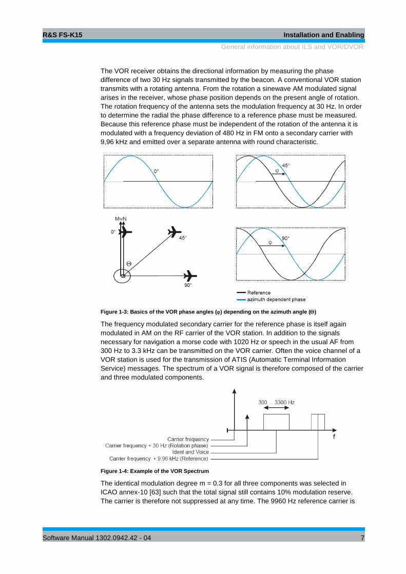
2.4 Avionics Demodulator Mode
The application firmware R&S FS-K15 (avionics demodulation measurements) is
activated with the AVIONICS hotkey.
SPECTRUM
AVIONICS
MRECEIVER NETWORK SCREEN BAVIONICS
The AVIONICS hotkey allows the access to the avionics measurement capabilities
(VOR/ILS) of the instrument.
A softkey menu suitable for the currently selected operating mode is simultaneously
displayed and allows the setting of the measurement parameters.
Simultaneously, the VOR demodulator is activated (default after Preset).
VOR
MODULATION
SPECTRUM .
AVIONICS
SETTINGS
DISTORT
ON OFF
DISTORTION
MAX FREQ
FUND FREQ
90/150 HZ
FSMR FSQ with opt.
B71
(baseband
input)
Instrument Model
FUND FREQ
150 HZ
THD UNIT
% DB
ILS
BASEBAND
DDM UNIT
% [1]
FUND FREQ
90 HZ
BASEBAND
ON OFF
BASEBAND
SENSITIVTI
INPUT LEV
4V 400mV
BASEBAND
ANALOG
BALANCED
ON OFF
RF PATH
FUND FREQ
IDENT
FUND FREQ
90/150 HZ
FUND FREQ
90 HZ
FUND FREQ
150 HZ
FUND FREQ
IDENT
BASEBAND
SENSITIVTI
HARMONIC
FREQ
INPUT IMP
1MΩ 50Ω
INPUT IMP
1MΩ 50Ω
The softkeys visible in the BASEBAND submenu depend on the instrument type. The
BASEBAND submenu is only available in the R&S FSMR and R&S FSQ equipped
with baseband inputs (option R&S FSQ-B71).
The individual settings are explained in the following menus.

R&S FS-K15 Configuration of the Avionics Demodulator
Result Display – RF level and frequency counter result
Software Manual 1302.0942.42 - 04 18
The main measurement functions of the avionics demodulator are:
VOR VOR Measurements
ILS ILS Measurements
MODULATION SPECTRUM Modulation Distortion measurements
In the avionics demodulator mode the base instrument is equipped with a high
performance avionics demodulator. In order to display the measurement results the
screen is divided in two halves.
The frequency setting, the frequency counter result and the RF or baseband input level
is displayed in the upper half of the screen. The measurement results of the avionics
demodulator are displayed in a table in the lower half of the screen. The modulation
spectrum can be displayed in the lower half as a trace.
Signal parameters such as modulation depth and frequency deviation can be
determined.
2.5 Result Display – RF level and frequency counter result
The upper screen shows the level readings and the frequency settings and frequency
counter result.
Example for upper screen:
Figure 2-1: RF Level measurement display
Screen description:
RF frequency Result from the frequency counter
Carrier Offset Frequency offset between measured frequency and tuned
frequency
Tuned Frequency RF Frequency setting
RF level RF level reading (Baseband input level in case of baseband
operation)
Bargraph for visual information about the input level
Status information flags for Power Splitter, Auto Tune, Average, AutoLevel etc.:
ATT Setting of the RF attenuator. Manual or Coupled to Reference level AQT This is the measurement time or capture time. RBW Display of actual resolution bandwidth for distortion measurement AUTO TUNE
Enhancement label for Autotune = ON.
AUTOL Enhancement label for level Autorange.
R&S FS-K15 Configuration of the Avionics Demodulator
Avionics Demodulator Main Menu
Software Manual 1302.0942.42 - 04 19
EVEL SPLITTER Enhancement label for Power Splitter Sensor head. The insertion loss of
the splitter will be taken into account in the RF level reading The individual measured values are read out with the following commands:
RF frequency CALC:AVI:RFFR:RES?
Carrier Offset CALC:AVI:FERR:RES?
RF level CALC:AVI:CARR:RES?
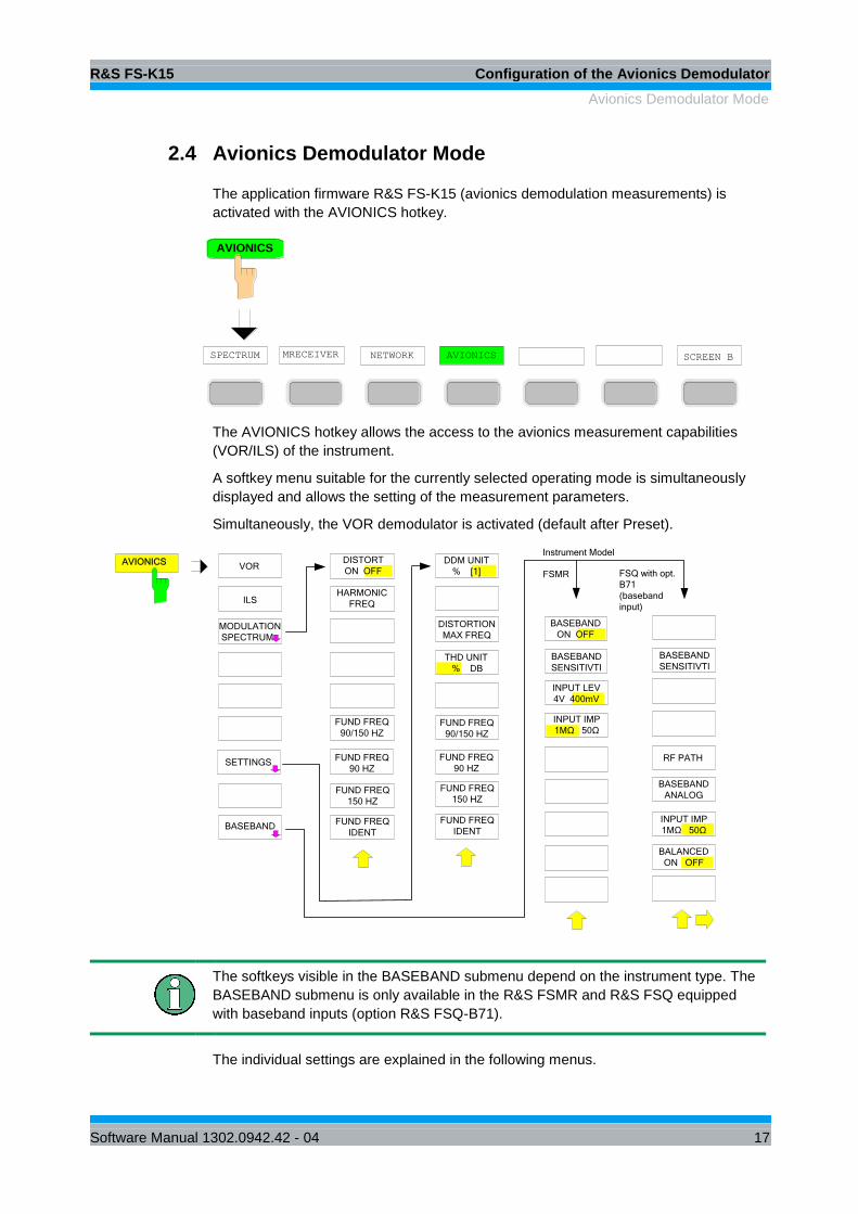
2.6 Avionics Demodulator Main Menu
The AVIONICS hotkey opens the menu for setting the VOR/ILS demodulator functions.
VOR The VOR softkey switches the VOR demodulator on. The VOR demodulator default
setting is OFF. When the AVIONICS mode is selected after preset, the demodulator is
switched on automatically.
Remote: CALC:AVI:STAN VOR
Figure 2-2: VOR measurement display
The settings of the spectrum analyzer active before the demodulator is switched on
will be restored when the demodulator is switched off. The center frequency setting is
coupled between the operating modes.
The trace operating mode and detector are restored (the VOR/ILS demodulator has
separate trace settings).
R&S FS-K15 Configuration of the Avionics Demodulator
Avionics Demodulator Main Menu
Software Manual 1302.0942.42 - 04 20
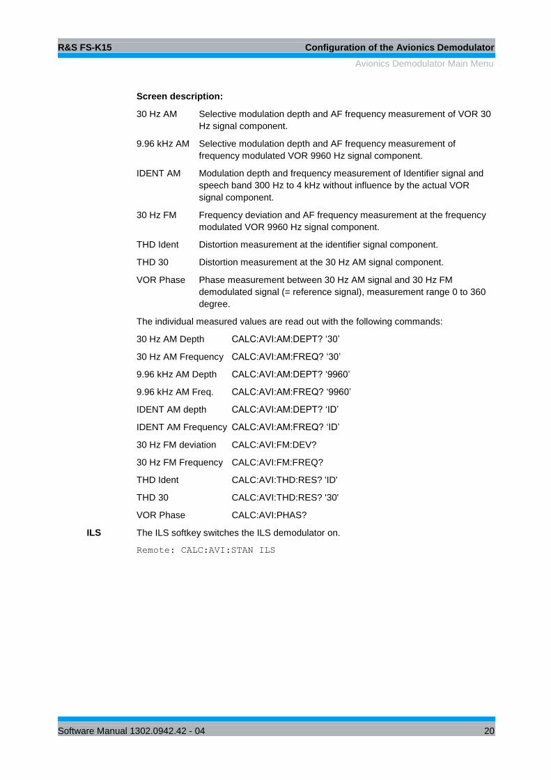
Screen description:
30 Hz AM Selective modulation depth and AF frequency measurement of VOR 30
Hz signal component.
9.96 kHz AM Selective modulation depth and AF frequency measurement of
frequency modulated VOR 9960 Hz signal component.
IDENT AM Modulation depth and frequency measurement of Identifier signal and
speech band 300 Hz to 4 kHz without influence by the actual VOR
signal component.
30 Hz FM Frequency deviation and AF frequency measurement at the frequency
modulated VOR 9960 Hz signal component.
THD Ident Distortion measurement at the identifier signal component.
THD 30 Distortion measurement at the 30 Hz AM signal component.
VOR Phase Phase measurement between 30 Hz AM signal and 30 Hz FM
demodulated signal (= reference signal), measurement range 0 to 360
degree.
The individual measured values are read out with the following commands:
30 Hz AM Depth CALC:AVI:AM:DEPT? ‘30’
30 Hz AM Frequency CALC:AVI:AM:FREQ? ‘30’
9.96 kHz AM Depth CALC:AVI:AM:DEPT? ‘9960’
9.96 kHz AM Freq. CALC:AVI:AM:FREQ? ‘9960’
IDENT AM depth CALC:AVI:AM:DEPT? ‘ID’
IDENT AM Frequency CALC:AVI:AM:FREQ? ‘ID’
30 Hz FM deviation CALC:AVI:FM:DEV?
30 Hz FM Frequency CALC:AVI:FM:FREQ?
THD Ident CALC:AVI:THD:RES? 'ID'
THD 30 CALC:AVI:THD:RES? '30'
VOR Phase CALC:AVI:PHAS?
ILS The ILS softkey switches the ILS demodulator on.
Remote: CALC:AVI:STAN ILS

R&S FS-K15 Configuration of the Avionics Demodulator
Avionics Demodulator Main Menu
Software Manual 1302.0942.42 - 04 21
Figure 2-3: ILS measurement display
The settings of the spectrum analyzer active before the demodulator is switched on
will be restored when the demodulator is switched off. The center frequency setting is
transferred between the operating modes.
Similarly, the trace operating mode and detector are restored (the VOR/ILS
demodulator has separate trace settings).
Screen description:
90 Hz AM Selective modulation depth and AF frequency measurement of 90 Hz ILS signal component.
150 Hz AM Selective modulation depth and AF frequency measurement of 150 Hz ILS signal component.
ILS Phase Phase angle measurement between 90 Hz and 150 Hz AM signal (90 Hz = reference signal), measurement range ±60 degree.
90+150 Hz AM Total modulation depth of the 90 Hz and the 150 Hz components taking the phase between the components into account.
IDENT AM Modulation depth and frequency measurement of Identifier signal and speech band 300 Hz to 4 kHz without influence by the actual ILS signal components.
SDM Selective measurement of the sum-modulation depth (SDM = Sum in Depth of Modulation); arithmetic sum of the modulation depth of the 90 Hz and the 150 Hz components without any influence of the phase between the components.
THD Ident Distortion measurement at the identifier signal component. DDM DDM (= difference in depth of modulation) between 90 Hz and
150 Hz AM signal (m90 Hz – m150 Hz). The individual measured values are read out with the following commands:
R&S FS-K15 Configuration of the Avionics Demodulator
Avionics Demodulator Main Menu
Software Manual 1302.0942.42 - 04 22
90 Hz AM depth CALC:AVI:AM:DEPT? ‘90’ 90 Hz AM Frequency CALC:AVI:AM:FREQ? ‘90’ 150 Hz AM depth CALC:AVI:AM:DEPT? ‘150’ 150 Hz AM Frequency CALC:AVI:AM:FREQ? ‘150’ 90+150 Hz AM depth CALC:AVI:AM:DEPTh? ‘90+150’ ILS Phase CALC:AVI:PHAS? IDENT AM depth CALC:AVI:AM:DEPT? ‘ID’ IDENT AM Frequency CALC:AVI:AM:FREQ? ‘ID’ SDM CALC:AVI:SDM? THD CALC:AVI:THD:RES? ‘’ DDM CALC:AVI:DDM?
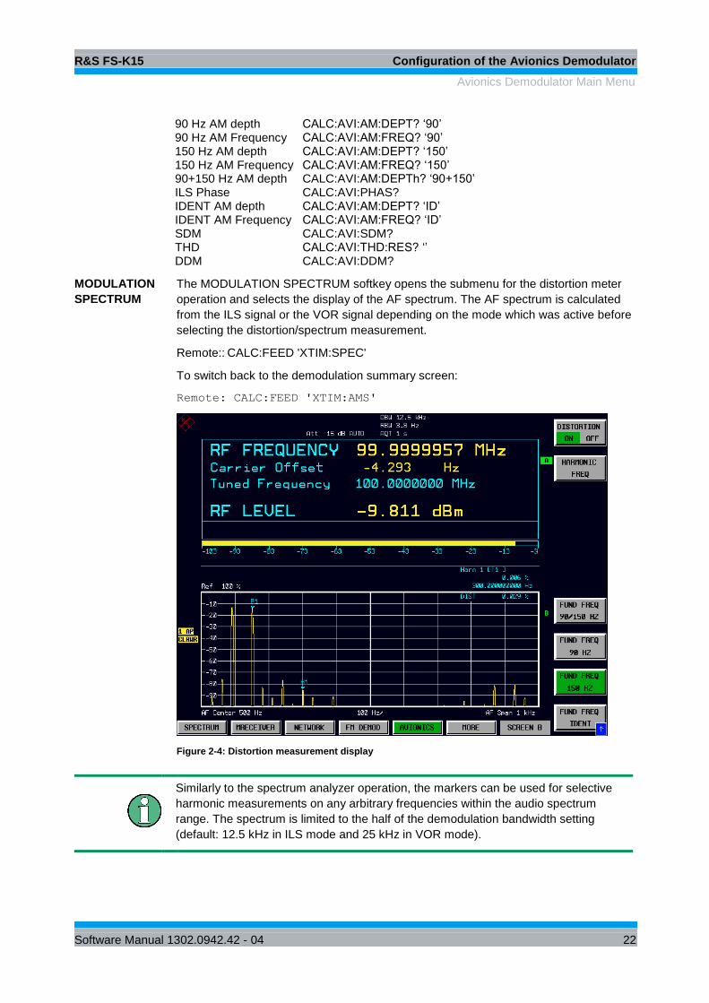
MODULATION
SPECTRUM
The MODULATION SPECTRUM softkey opens the submenu for the distortion meter
operation and selects the display of the AF spectrum. The AF spectrum is calculated
from the ILS signal or the VOR signal depending on the mode which was active before
selecting the distortion/spectrum measurement.
Remote:: CALC:FEED 'XTIM:SPEC'
To switch back to the demodulation summary screen:
Remote: CALC:FEED 'XTIM:AMS'
Figure 2-4: Distortion measurement display
Similarly to the spectrum analyzer operation, the markers can be used for selective
harmonic measurements on any arbitrary frequencies within the audio spectrum
range. The spectrum is limited to the half of the demodulation bandwidth setting
(default: 12.5 kHz in ILS mode and 25 kHz in VOR mode).
R&S FS-K15 Configuration of the Avionics Demodulator
Avionics Demodulator Main Menu
Software Manual 1302.0942.42 - 04 23
Screen description:
DIST Distortion measurement at the selected signal component.
The measured value are read out with the following command:
Remote: CALC:AVI:SHD:RES?
DISTORTION
ON OFF
The DISTORTION ON OFF softkey activates the harmonic distortion measurement.
Remote: CALC:AVI:SHD:STAT ON | OFF
HARMONIC
FREQUENCY
The HARMONIC FREQUENCY softkey sets the measurement frequency of the
harmonic distortion measurement. This setting is only taken into account for the
distortion reading in the distortion screen.
Remote: CALC:AVI:SHD:FREQ 300HZ
The result of the manual distortion measurement is available with the following
command:
Remote: CALC:AVI:SHD:RES?
FUND FREQ
90/150HZ
The FUND FREQ 90/150HZ softkey sets the reference frequency for the harmonic
distortion reading to the 90 Hz and 150 Hz signal. Both modulation tones will be
measured and the average level will be used as reference. This allows THD
measurements at signals with non-equal tone modulation (DDM not zero). All
harmonics at N * 30 Hz will be measured and the distortion result is calculated in % or
dB to the average of the 90 Hz and 150 Hz signal level.
Remote: CALC:AVI:THD:FREQ:FUND '90_150'
FUND FREQ 90
HZ
The FUND FREQ 90 HZ softkey sets the reference frequency for the harmonic
distortion reading to the 90 Hz signal. All harmonics at N * 90 Hz will be measured and
the distortion result is calculated in % or dB to the 90 Hz signal level.
Remote CALC:AVI:THD:FREQ:FUND '90'
FUND FREQ
150 HZ
The FUND FREQ 150 HZ softkey sets the reference frequency for the harmonic
distortion reading to the 150 Hz signal. All harmonics at N * 150 Hz will be measured
and the distortion result is calculated in % or dB to the 150 Hz signal level.
Remote: CALC:AVI:THD:FREQ:FUND '150'
FUND FREQ
IDENT
The FUND FREQ IDENT softkey sets the fundamental frequency for the harmonic
distortion reading to the Identifier signal. The THD measurement will use the highest
signal in the frequency range from 300 Hz to 4 kHz as the fundamental signal
reference.
Remote: CALC:AVI:THD:FREQ:FUND 'ID'
SETTINGS The SETTINGS softkey opens the submenu for setting the measurement parameters
of the selected measurement function.
DDM UNIT
% [1]
The DDM UNIT %/1 softkey selects between % and unitfree for displaying the DDM
measurement results of the ILS demodulator.
Remote: UNIT:DDM PCT | UNIT

R&S FS-K15 Configuration of the Avionics Demodulator
Avionics Demodulator Main Menu
Software Manual 1302.0942.42 - 04 24
DISTORTION
MAX FREQ
The DISTORTION MAX FREQ softkey sets the upper frequency limit of the total
harmonic distortion measurement.
Remote: CALC:AVI:THD:FREQ:UPP
DIST UNIT %/DB The DIST UNIT %/DB softkey selects between % and dB for displaying the THD
measurement results.
Remote: UNIT:THD PCT
FUND FREQ
90/150HZ
The FUND FREQ 90/150HZ softkey sets the reference frequency for the harmonic
distortion reading to the 90 Hz and 150 Hz signal. Both modulation tones will be
measured and the average level will be used as reference. This allows THD
measurements at signals with non-equal tone modulation (DDM not zero). All
harmonics at N * 30 Hz will be measured and the distortion result is calculated in % or
dB to the average of the 90 Hz and 150 Hz signal level.
Remote: CALC:AVI:THD:FREQ:FUND '90_150'
FUND FREQ 90
HZ
The FUND FREQ 90 HZ softkey sets the reference frequency for the harmonic
distortion reading to the 90 Hz signal. All harmonics at N * 90 Hz will be measured and
the distortion result is calculated in % or dB to the 90 Hz signal level.
Remote: CALC:AVI:THD:FREQ:FUND '90'
FREQ 150 HZ The FUND FREQ 150 HZ softkey sets the reference frequency for the harmonic
distortion reading to the 150 Hz signal. All harmonics at N * 150 Hz will be measured
and the distortion result is calculated in % or dB to the 150 Hz signal level.
Remote: CALC:AVI:THD:FREQ:FUND '150'
FUND FREQ
IDENT
The FUND FREQ IDENT softkey sets the fundamental frequency for the harmonic
distortion reading to the Identifier signal. The THD measurement will use the highest
signal in the frequency range from 300 Hz to 4 kHz as the fundamental signal
reference.
Remote: CALC:AVI:THD:FREQ:FUND 'ID'
BASEBAND FUND FREQ IDENT (present at the RF input of the instrument) the modulation signal
at the audio input or the baseband input is analyzed. The input level range is fixed (no
autorange). In all VOR/ILS modulation depth measurements the selectively measured
voltages are converted into modulation depth and read out in %AM, the sensitivity
entered under Baseband Sensitivity in Volöts/100% being used as a reference. This
applies also to the ILS measurements DDM, SDM and m(90+150)Hz derived from the
90 and 150 Hz tones modulation depth measurements. When baseband
measurements are selected, the RF input is switched off.
The baseband menu is only available when the instrument is equipped with an audio
input (R&S FSMR) or with the option baseband inputs (R&S FSQ-B71).
The baseband signal shall be connected to the “I” baseband input on the R&S FSQ.
R&S FS-K15 Configuration of the Avionics Demodulator
Avionics Demodulator Main Menu
Software Manual 1302.0942.42 - 04 25
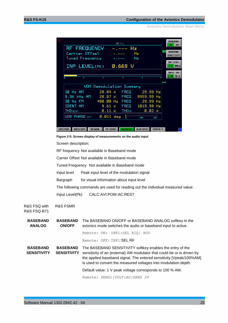
Figure 2-5: Screen display of measurements on the audio input
Screen description:
RF frequency Not available in Baseband mode
Carrier Offset Not available in Baseband mode
Tuned Frequency Not available in Baseband mode
Input level Peak input level of the modulation signal
Bargraph for visual information about input level
The following commands are used for reading out the individual measured value:
Input Level(Pk) CALC:AVI:POW:AC:RES?
R&S FSQ with
R&S FSQ-B71
R&S FSMR
BASEBAND
ANALOG
BASEBAND
ON/OFF
The BASEBAND ON/OFF or BASEBAND ANALOG softkey in the
avionics mode switches the audio or baseband input to active.
Remote: ON: INP1:SEL AIQ| AUD
Remote: OFF: INP1:SEL RF
BASEBAND
SENSITIVITY
BASEBAND
SENSITIVITY
The BASEBAND SENSITIVITY softkey enables the entry of the
sensitivity of an (external) AM modulator that could be or is driven by
the applied baseband signal. The entered sensitivity [Vpeak/100%AM]
is used to convert the measured voltages into modulation depth.
Default value: 1 V peak voltage corresponds to 100 % AM.
Remote: SENS1:VOLT:AC:SENS 2V

R&S FS-K15 Configuration of the Avionics Demodulator
FREQ Key
Software Manual 1302.0942.42 - 04 26
Use reference
level setting in
amplitude menu.
INP LEVEL
4V/400mV
The INP LEVEL 4V/400mV softkey switches the input voltage range of
the audio input between 4 V and 400 mV.
In the default setting, the 4 V range is switched on.
Remote: SENS1:VOLT:AC:RANG:UPP 0.4V
I/Q INPUT
50Ω/1MΩ
INPUT IMP
50Ω/1MΩ
The INPUT IMP 50Ω/1MΩ or I/Q INPUT 50Ω/1MΩ softkey switches the
input impedance of the audio input between 50 Ω and 1 MΩ.
Note: The baseband input impedance on the R&S FSQ depends on the
model. Older models offer 50Ω/1kΩ impedance settings.
In the default setting, the input impedance is set to 1 MΩ.
Remote: INP1:IMP 50OHM
BALANCED
ON/OFF
The BALANCED ON/OFF softkey switches the baseband input between
balanced and unbalanced mode. (only R&S FSQ-B71).
In the default setting, the balanced mode is switched on.
Remote: INP1:IQ:BAL ON
2.7 FREQ Key
The FREQ key opens the RF frequency menu. The menu allows to set the RF
frequency tuning mode on the instrument. In the default status the analyzer is set to
manual tuning mode and 100 MHz receiver frequency. The keys for the RF frequency
variation are not available in the baseband mode.

R&S FS-K15 Configuration of the Avionics Demodulator
FREQ Key
Software Manual 1302.0942.42 - 04 27
FREQRECEIVER
FREQUENCY
STEPSIZE
SIGNAL
TRACK
TRACKING
ON OFF
AUTO
COARSE
AUTO
FINE
STEPSIZE
=FREQ
STEPSIZE
MANUAL
AF START
AF STOP
AF CENTER
SINGLE
AUTOTUNE
AUTOTUNE
THRESHOLD
TRACK
ONCE
RECEIVER
FREQUENCY
The RECEIVER FREQUENCY softkey activates the window for entering the receiver
frequency.
The receiver frequency resolution is 0.1 Hz.
Setting range: 20 Hz fREC fmax
Remote: SENS:FREQ:CENT 300MHz
STEPSIZE The STEPSIZE softkey opens a submenu for setting the step size of the receive
frequency. The step size can either be coupled to the set frequency or be manually set
to a fixed value. The menu softkeys are selection switches, and only one of them at a
time can be active.
AUTO AUTO
COARSE
COARSE
The AUTO COARSE softkey sets the step size of the receive frequency to coarse. In
this setting, the fourth position of the set frequency is varied.
Remote: ---
AUTO
FINE
The AUTO FINE softkey sets the step size of the receive frequency to fine. The
seventh position of the set frequency is varied in this setting.
Remote: ---
STEPSIZE
MANUAL
The STEPSIZE MANUAL softkey activates the window for entering a fixed value for
the step size.
Remote: FREQ:CENT:STEP 50 kHz

R&S FS-K15 Configuration of the Avionics Demodulator
FREQ Key
Software Manual 1302.0942.42 - 04 28
STEPSIZE
= FREQ
The STEPSIZE = FREQ softkey sets the step size to the receive frequency value. This
function is particularly useful for measuring the harmonics of a signal. If the receiver is
first tuned to the fundamental, the frequency of another harmonic is set with each
frequency variation by using the rotary knob or the STEP keys.
Remote: ---
AUTOTUNE
THRESHOLD
The AUTOTUNE THRESHOLD softkey activates the window for entering the threshold
level of the autotune function. This function is only available for instrument models up
to a maximum frequency of 26.5 GHz.
The autotune threshold default setting is -40 dBm.
Setting range -50 dBm Threshold level 0 dBm
Remote: SENS:FREQ:CW:AFC:THR <numeric_value>
SINGLE
AUTOTUNE
This softkey activates a single automatic signal search.Q
Remote: SENS:FREQ:CW:AFC ONCE
SIGNAL
TRACK
This softkey activates a function to track a drifting signal. If the measured signal
frequency is too far away from the tuned center frequency and the level is above the
threshold, the center frequency of the receiver will be changed to the new signal
frequency.
Remote: SENS:FREQ:CW:AFC ON
TRACK
ONCE
This softkey activates a single frequency setting to align the tuned frequency to the
signal. If the measured signal frequency is too far away from the tuned center
frequency and the level is above the threshold, the center frequency of the receiver will
be changed to the new signal frequency.
Remote: SENS:FREQ:CW:AFC ON'
SENS:FREQ:CW:AFC:STR ONCE
AF CENTER The AF CENTER softkey allows the user to select the center frequency within the AF
spectrum.
Remote: SENS:ADEM:AF:CENT 1KHZ
AF START The AF START softkey allows the user to select the start frequency within the AF
spectrum.
Remote: SENS:ADEM:AF:STAR 0HZ
AF STOP The AF STOP softkey allows the user to select the stop frequency within the AF
spectrum.
The maximum AF stop frequency corresponds to half the demodulation bandwidth.
Remote: SENS:ADEM:AF:STOP 2KHZ

R&S FS-K15 Configuration of the Avionics Demodulator
SPAN Key
Software Manual 1302.0942.42 - 04 29
2.8 SPAN Key
DEMOD
BW
AF
FULL SPAN
AF SPANSPAN
The SPAN menu allows the user to select the frequency range to be displayed.
The Span softkey is only available when the modulation spectrum is active.
AF SPAN The AF SPAN softkey allows the user to select the frequency range if the modulation
spectrum display is active.
Values between the sampling rate/200 and the demodulation bandwidth/2 can be
selected.
Remote: SENS:ADEM:AF:SPAN 2.5 kHz
AF
FULL SPAN
The AF FULL SPAN softkey sets the maximum frequency range if the AF spectrum
displays are active.
The maximum frequency range corresponds to half the demodulation bandwidth.
Remote: SENS:ADEM:AF:SPAN:FULL
DEMOD
BW
The demodulation bandwidth of the avionics demodulator is selected using the
DEMOD BW softkey. The demodulation bandwidth determines the sampling rate for
recording the signal to be analyzed. The DEMOD BW MANUAL softkey is only
available in ILS demodulation mode. The bandwidth can be set to 12.5 kHz, 3.2 kHz
and 800 Hz. This function can be used to suppress adjacent transmitters.
Remote: SENS:BAND:DEM 3.2KHZ

R&S FS-K15 Configuration of the Avionics Demodulator
AMPT Key
Software Manual 1302.0942.42 - 04 30
2.9 AMPT Key
2.9.1 Setting the Level Display and Configuring the RF Input – AMPT Key
The AMPTkey is used to set the reference level, the maximum level and the display
range as well as the input impedance and the input attenuation of the RF input.
Further settings regarding the level display RF attenuation, the preamplifier and the
autorange function can be made in this menu.
When the instrument is in default status, it is in autorange mode, i.e. the input level is
automatically set depending on the measured peak level. In the default setting the
measurement time is set to 1s, this allows the auto level routine to find the peak level
for modulation frequencies down to 10 Hz.
For special cases, e.g. if a input signal is only temporarily applied, the RF level can
also be manually set to a fixed value using the reference level function. This leads to
improved measurement speed and saves unwanted switching of the mechanical
attenuator. When manual level setting is activated, the current valid setting of the auto
level function will be maintained when autorange was active before.
RF INPUT
REF LEVEL
RF LEVEL
AUTORANGE
AUTORANGE
CONFIG
RANGE
RF INPUT
AC DC
RF ATTEN
MANUAL
RF ATTEN
AUTO
MIXER
10 dB MIN
ON OFF
AUTOPREAMP
ON OFF
REFERENCE
POSITION
REFERENCE
VALUE
DEVIATION
LIN LOG
DB
PER DIV
MIXER LVL
AUTO
MIXER LVL
MANUAL
Option
FSx-B23/
B24/25
AMPT
LEVEL
OFFSET
DEVIATION
PER DIV
UNITS
LEVEL UNIT
dBm
LEVEL UNIT
dBuV
LEVEL UNIT
Watt
REF LEVEL The REF LEVEL softkey activates the window for entering the reference level. The
entry is made in the currently active unit (dBm, dBµV, etc).
Remote: DISP:WIND:TRAC:Y:RLEV -60dBm

R&S FS-K15 Configuration of the Avionics Demodulator
AMPT Key
Software Manual 1302.0942.42 - 04 31
The REF LEVEL value defines the clipping level of the A/D converter and must
therefore be set greater than or equal to the maximum power of the signal to be
analyzed.
RF LEVEL AUTORANGE
The RF LEVEL AUTORANGE softkey activates the autorange function; attenuation,
IF gain and, if necessary, preamplification, are automatically matched to the applied
RF signal.
Remote: DISP:WIND:TRAC:Y:RLEV:AUTO ON
AUTORANGE CONFIG
The AUTORANGE CONFIG softkey opens a submenu for configuring the automatic
setting of attenuation and IF gain and, if necessary, preamplification.
10 dB MIN ON/OFF
The 10 dB MIN ON/OFF softkey determines whether or not the 0 dB position of the
attenuator is used when setting the insertion manually or automatically.
The default setting is 10 dB MIN OFF.
With 10 dB MIN ON an RF attenuation of at least 10 dB is always switched on in the
instrument to ensure specific adjustment.
Even manually, the 0 dB position cannot be switched on.
Remote: INP:ATT:PROT ON
AUTO PREAMP ON/OFF
The AUTO PREAMP ON/OFF softkey activates the preamplifier for the autorange
function.
ON The autorange function takes the preamplifier into account. The preamplifier is
activated only when the attenuation of the attenuator has been reduced to the
minimum settable value.
OFF The auto range does not take into account the preamplifier.
The softkey is only available with the R&S FSx-B23/B24/B25 preamplifier option.
Remote: INP:GAIN:AUTO ON
RANGE The RANGE softkey opens a submenu for determining the diagram scaling for the
selected measurement.
The softkeys visibility depends on the selected measurement function (only for
modulation spectrum).
REFERENCE POSITION
The REFERENCE POSITION softkey defines the position of the reference line.
The entry is in percentage of the diagram height, where 100% corresponds to the top
edge of the diagram. The default setting is 100 % (top edge of diagram) for displaying
the AF spectrum of the signal.
Remote: DISP:WIND:TRAC:Y:RPOS 50PCT
REFERENCE VALUE
The REFERENCE VALUE softkey defines the modulation depth at the at the
reference line of the y axis.

R&S FS-K15 Configuration of the Avionics Demodulator
AMPT Key
Software Manual 1302.0942.42 - 04 32
The settable value range is 0.0001% to 10000%.
Remote: DISP:WIND:TRAC:Y:RVAL 100PCT
DEVIATION LIN/LOG
The DEVIATION LIN/LOG softkey switches between logarithmic and linear
modulation spectrum display.
Remote: DISP:WIND:TRAC:Y:SPAC LOG
DB PER DIV
The DB PER DIV softkey allows to scale the modulation depth in the range from
0.1 dB/div to 20 dB/div.
The softkey is not available with linear display.
Remote: DISP:WIND:TRAC:Y:PDIV 5DB
UNIT The UNIT softkey opens a submenu from which the desired unit for the y axis can be
selected.
The default setting is dBm.
In general, the analyzer measures the signal voltage at the RF input. The level
display is calibrated in rms values of an unmodulated sinewave signal. In the default
state, the level is displayed at a power of 1 mW (= dBm). Via the known input
resistance, conversion to other units is possible. The units dBm, dBV and W are
directly convertible.
Remote: CALC:UNIT:POW DBM
dBm The dBm softkey selects the unit dBm for displaying the RF level measurement
results.
Watt The Watt softkey selects the unit Watt for displaying the RF level measurement
results.
dBuV The dBuV softkey selects the unit dBuV for displaying the RF level measurement
results.
RF INPUT AC/DC
The RF INPUT AC/DC softkey switches the analyzer input between AC and DC
coupling.
Note:
The softkey is not available in all models.
Remote: INP:COUP AC
RF ATTEN MANUAL
The RF ATTEN MANUAL softkey activates the window for entering attenuation
independently of the reference level.
The attenuation can be altered in 5 dB steps between 0 dB and 75 dB. Other entries
are rounded down to the next lowest integral value.
If the specified reference level can no longer be set with the specified RF attenuation,
the level is adjusted and the "Limit reached" message is displayed.
Note:
The 0 dB value cannot be switched on unless the 10 dB MIN function is off. This
protects the input mixer from overloading by mistake.
Remote: INP:ATT 40 DB

R&S FS-K15 Configuration of the Avionics Demodulator
AMPT Key
Software Manual 1302.0942.42 - 04 33
RF ATTEN AUTO
The RF ATTEN AUTO softkey automatically sets the RF attenuation depending on
the set reference level.
This ensures that the optimum RF attenuation is always used.
RF ATTEN AUTO is the default setting.
Remote: INP:ATT:AUTO ON
MIXER The MIXER softkey opens a submenu for changing the mixer level on the input mixer.
MIXER LVL AUTO
The MIXER LVL AUTO softkey activates the automatic coupling of the maximum
mixer level to the reference level and the RF attenuation.
Remote: INP:MIX:AUTO ON
MIXER LVL MANUAL
The MIXER LVL MANUAL softkey activates the window for entering the maximum
mixer level that can be achieved with reference levels.
The setting range is 0 dB to -100 dBm with a step size of 1 dB.
Remote: INP:MIX -25DBM
RF INPUT 50 Ω / 75 Ω
The RF INPUT 50 Ω / 75 Ω softkey switches the reference impedance for the
measured level values between 50 Ω (= default setting) and 75 Ω.
Select the 75 Ω setting if the 50 Ω input impedance is transformed to the next higher
impedance by using a 75 Ω matching pad of the RAZ type (= 25 Ω in series with the
input impedance of the analyzer). The correction value used is 1.76 dB = 10 log
(75 Ω/50 Ω).
All level specifications in this manual refer to the default setting (50
Remote: INP:IMP 50 OHM
2.9.2 Setting the Level Display at the Baseband Input – AMPT Key
In Baseband mode the AMPT key allows to set the display range in the modulation
spectrum display.
REF LEVEL The REF LEVEL softkey activates the window for entering the peak reference
level.
Remote: DISP:WIND:TRAC:Y:RLEV 1V
The REF LEVEL value defines the clipping level of the A/D converter and must
therefore be set greater than or equal to the maximum peak voltage of the signal to be
analyzed.
RANGE The RANGE softkey opens a submenu for configuring the Y-axis in the graphical
display of the modulation spectrum measurement results.

R&S FS-K15 Configuration of the Avionics Demodulator
BW Key
Software Manual 1302.0942.42 - 04 34
REFERENCE
POSITION
The REFERENCE POSITION softkey defines the position of the reference line.
The entry is in percentage of the diagram height, where 100% corresponds to the
top edge of the diagram. The default setting is 100% (top edge of diagram) for
displaying the AF spectrum of the signal.
Remote: DISP:WIND:TRAC:Y:RPOS 50PCT
REFERENCE
VALUE
The REFERENCE VALUE softkey defines the modulation depth at the top edge
of the diagram.
The settable value range is 0% to 10000%.
Remote:DISP:WIND:TRAC:Y:RVAL 100PCT
DEVIATION
LIN/LOG
The DEVIATION LIN/LOG softkey switches between logarithmic and linear
modulation spectrum display.
Remote: DISP:WIND:TRAC:Y:SPAC LOG
DB
PER DIV
The DB PER DIV softkey allows you to select the modulation depth in the range
from 0.1 dB/div to 20 dB/div.
The softkey is not available with linear display.
Remote: DISP:WIND:TRAC:Y:PDIV 5DB
2.10 BW Key
2.10.1 Setting the Bandwidths and the Measurement Time – BW Key
BWDEMOD BW
AUTO
DEMOD BW
MANUAL
IF BW
AUTO
IF BW
MANUAL
MEAS TIME
AUTO
MEAS TIME
MANUAL
RES BW
MANUAL
R&S FS-K15 Configuration of the Avionics Demodulator
BW Key
Software Manual 1302.0942.42 - 04 35
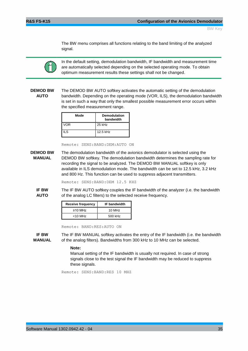
The BW menu comprises all functions relating to the band limiting of the analyzed
signal.
In the default setting, demodulation bandwidth, IF bandwidth and measurement time
are automatically selected depending on the selected operating mode. To obtain
optimum measurement results these settings shall not be changed.
DEMOD BW
AUTO
The DEMOD BW AUTO softkey activates the automatic setting of the demodulation
bandwidth. Depending on the operating mode (VOR, ILS), the demodulation bandwidth
is set in such a way that only the smallest possible measurement error occurs within
the specified measurement range.
Mode Demodulation bandwidth
VOR 25 kHz
ILS 12.5 kHz
Remote: SENS:BAND:DEM:AUTO ON
DEMOD BW
MANUAL
The demodulation bandwidth of the avionics demodulator is selected using the
DEMOD BW softkey. The demodulation bandwidth determines the sampling rate for
recording the signal to be analyzed. The DEMOD BW MANUAL softkey is only
available in ILS demodulation mode. The bandwidth can be set to 12.5 kHz, 3.2 kHz
and 800 Hz. This function can be used to suppress adjacent transmitters.
Remote: SENS:BAND:DEM 12.5 KHZ
IF BW
AUTO
The IF BW AUTO softkey couples the IF bandwidth of the analyzer (i.e. the bandwidth
of the analog LC filters) to the selected receive frequency.
Receive frequency IF bandwidth
≥10 MHz 10 MHz
<10 MHz 500 kHz
Remote: BAND:RES:AUTO ON
IF BW
MANUAL
The IF BW MANUAL softkey activates the entry of the IF bandwidth (i.e. the bandwidth
of the analog filters). Bandwidths from 300 kHz to 10 MHz can be selected.
Note:
Manual setting of the IF bandwidth is usually not required. In case of strong
signals close to the test signal the IF bandwidth may be reduced to suppress
these signals.
Remote: SENS:BAND:RES 10 MHZ

R&S FS-K15 Configuration of the Avionics Demodulator
BW Key
Software Manual 1302.0942.42 - 04 36
MEAS TIME
AUTO
The MEAS TIME AUTO softkey activates automatic coupling of the measurement time.
Mode Measurement time
VOR 1000 ms
ILS 1000 ms
Distortion 1000 ms
Note:
To obtain a correct result display, at least five periods of the demodulated signal
should be monitored. If the modulation frequencies are low, it may be useful to
manually prolong the measurement time (= signal monitoring time).
Remote: SENS:SWE:TIME:AUTO ON
MEAS TIME
MANUAL
The MEAS TIME MANUAL softkey opens the entry field for determining the data
acquisition time. The permissible value range depends on the selected demodulation
bandwidth:
Note:
To obtain a correct result display, at least five periods of the demodulated signal
should be monitored.
Remote: SENS:SWE:TIME 800 MS
RES BW
MANUAL
If the spectrum display is active, the RES BW MANUAL softkey selects the resolution
bandwidth for the displayed signal. Note that these resolution bandwidths are
implemented as FFT filters.
Note:
The softkey is only available if the modulation spectrum result displays is active.
Remote: SENS:ADEM:SPEC:BAND:RES 10 Hz

R&S FS-K15 Configuration of the Avionics Demodulator
SWEEP Key
Software Manual 1302.0942.42 - 04 37
2.11 SWEEP Key
2.11.1 Setting the Sweep – SWEEP/MEAS Keys
SWEEPCONTINUOUS
SWEEP
SINGLE
SWEEP
MEAS TIME
AUTO
MEAS TIME
MANUAL
SWEEP
COUNT
SGL SWEEP
DISP OFF
The SWEEP key calls a menu in which the sweep mode is defined.
The CONTINUOUS SWEEP, SINGLE SWEEP and SGL SWEEP DISP OFF softkeys
are mutually exclusive selection keys.
CONTINUOUS
SWEEP
The CONTINUOUS SWEEP softkey sets the continuous sweep, i.e. the sweep
occurs continuously in accordance with the trigger setting.
CONTINUOUS SWEEP is the default setting of the instrument.
Remote: INIT:CONT ON
SINGLE
SWEEP
The SINGLE SWEEP softkey starts an n-times sweep after the trigger event has
occurred. The SWEEP COUNT softkey defines the number of sweeps.
If a trace is sampled with TRACE AVERAGE or MAXHOLD, the value set with the
SWEEP COUNT softkey defines the number of measurements. If the value is 0, a
sweep is performed.
Remote: INIT:CONT OFF;:INIT

R&S FS-K15 Configuration of the Avionics Demodulator
SWEEP Key
Software Manual 1302.0942.42 - 04 38
MEAS TIME
AUTO
The MEAS TIME AUTO softkey activates the automatic coupling of measurement
time.
Mode Measurement time
VOR 1000 ms
ILS 1000 ms
Distortion 1000 ms
Note:
To obtain a correct result display, at least five periods of the demodulated
signal should be monitored. If the modulation frequencies are low, it may be
useful to manually prolong the measurement time (= signal monitoring time).
Remote: SWE:TIME:AUTO ON
MEAS TIME
MANUAL
The MEAS TIME MANUAL softkey opens the entry field for determining the data
acquisition time. The permissible value range depends on the selected
demodulation bandwidth:
Demodulation bandwidth
min. measurement
time
max. measurement
time
25 kHz 600 ms 4.178 s
12.5 kHz 600 ms 8.356 s
3.2 kHz 601 ms 33.4 s
800 Hz 601 ms 133 s
Note:
To obtain a correct result display, at least five periods of the demodulated
signal should be monitored.
Remote: SENS:SWE:TIME 800 MS

R&S FS-K15 Configuration of the Avionics Demodulator
SWEEP Key
Software Manual 1302.0942.42 - 04 39
SWEEP
COUNT
The SWEEP COUNT softkey activates the window for entering the number of
sweeps that the instrument performs after a single sweep has been started. If Trace
Average, Max Hold or Min Hold has been activated, the number of averages or
maximum value findings is specified as well.
Example:
[TRACE1: MAX HOLD]
[SWEEP: SWEEP COUNT: 10 ENTER]
[SINGLE SWEEP]
The instrument performs the Max Hold function across ten sweeps.
The value range permissible for the sweep count is 0 to 32767. If the sweep count
is 0 or 1, a sweep is performed. With trace averaging and if the sweep count is 0,
the instrument performs sliding averaging across ten sweeps in continuous sweep
mode; if the sweep count is 1, no averaging occurs.
The sweep count is valid for all traces in a diagram.
Note:
Setting the number of sweeps in the Trace menu is identical with setting them
in the Sweep menu.
In the SINGLE SWEEP setting, the measurement is stopped once the selected
number of sweeps has been reached.
Remote: SENS:SWE:COUN 64
SGL SWEEP
DISP OFF
The SGL SWEEP DISP OFF softkey starts a sweep and switches off the display
during a single sweep. Once the sweep is completed, the display is reactivated and
the trace displayed.
Remote: INIT:DISP OFF;:INIT

R&S FS-K15 Configuration of the Avionics Demodulator
TRIG Key
Software Manual 1302.0942.42 - 04 40
2.12 TRIG Key
TRIGGER
OFFSET
FREE
RUNTRIGGER
EXTERN
POLARITY
POS NEG
IF POWER
RF POWER
The TRIG key opens a menu for setting the different trigger sources and for selecting
the trigger polarity. The active trigger mode is indicated by highlighting the associated
softkeys.
To indicate that a trigger mode other than FREE RUN has been set, the TRG
enhancement label is displayed on the screen. If two measurement windows are
displayed, TRG is indicated next to the window in question.
The available TRIGGER menu functions are identical to those of the base unit.
Video Trigger and Gated Trigger are not available in the avionics mode.

R&S FS-K15 Configuration of the Avionics Demodulator
MKR Key
Software Manual 1302.0942.42 - 04 41
2.13 MKR Key
ALL MARKER
OFF
MARKER 4
MARKER
NORM DELTA
MARKER 3
MARKER 2
MARKER 1MKR
The available MKR menu functions are identical to those of the base unit.
The MKR menu is only available when the modulation spectrum is active.
2.14 MKR -> Key
NEXT PEAK
PEAK
EXCURSION
MKR SELECT
MARKER
CENTER
=MKR FREQ
SEARCH
LIMITS
MRK->TRACE
PEAK MIN
NEXT
MIN RIGHT
NEXT
PEAK LEFT
NEXT
PEAK RIGHT
NEXT
MIN LEFT
NEXT MIN
The available MKR menu functions are identical to those of the base unit.
The MKR menu is only available when the modulation spectrum is active.

R&S FS-K15 Configuration of the Avionics Demodulator
MKR FCTN Key
Software Manual 1302.0942.42 - 04 42
2.15 MKR FCTN Key
MKR MKR
SELECT
MARKER
SHAPE FACT
60:3 60:6
MRK->TRACE
AMPTSPAN
PEAK
FCTN
The available MKR FCTN menu functions are identical to those of the base unit.
The MKR FCTN menu is only available when the modulation spectrum is active.
2.16 TRACE Key
CLEAR
WRITE
/
MAX HOLD
MIN HOLD
AVERAGE
VIEW
SWEEP
COUNT
TRACESELECT
TRACE
AVG MODE
(LOG)
BLANK
ASCII FILE
EXPORT
DECIM SEP
. ,
The available TRACE menu functions are identical to those of the base unit.
R&S FS-K15 Configuration of the Avionics Demodulator
DISP Key
Software Manual 1302.0942.42 - 04 43
The function Trace Math and Trace Detector is not available in the avionics
demodulator.
The TRACE menu is only available when the modulation spectrum is active.
2.17 DISP Key
DISPLAY CONFIG
DISPLAY
The available CONFIG DISPLAY menu functions are identical to those of the base
unit.
2.18 Other Keys
The functions of the other keys are identical to those of the base unit. Please refer to
the relevant chapters in the operating manual of the base unit.

R&S FS-K15 Remote Control Commands
Common Commands
Software Manual 1302.0942.42 - 04 44
3 Remote Control Commands
This chapter describes the remote control commands for the application firmware. An
alphabetic list following the text of the manual provides a quick overview of the commands.
The commands that also apply to the base unit in the SPECTRUM mode and the
system settings are described in the operating manual for the analyzer.
3.1 Common Commands
*OPT?
OPTION IDENTIFICATION QUERY polls the options contained in the device and
returns a list of installed options. The options are separated by commas. The identifier
for option R&S FS-K15 is contained in the response string at position 57.
Example 0,0, /……/ ,0,0,0,0,0,0,K15,0,0,0,0,0,0,0
3.2 CALCulate Subsystem
3.2.1 CALCulate:AVIonics Subsystem
The CALCulate:AVIonics subsystem controls the settings of the instrument for avionics
measurements.
CALCulate:AVIonics[:STANdard:]
This command sets the avionics demodulation mode.
Parameters
VOR: VOR demodulation
ILS: ILS demodulation
Example
CALC:AVI:STAN VOR
‘sets the avionics demodulator mode to VOR
Characteristics
* RST value: VOR
SCPI: device-specific
CALCulate:AVIonics:AM[:DEPTh]?
This command queries the results of the AM modulation depth measurement.
Parameters
<string> =

R&S FS-K15 Remote Control Commands
CALCulate Subsystem
Software Manual 1302.0942.42 - 04 45
’30’ AM modulation depth VOR 30 Hz
’90’ AM modulation depth ILS 90 Hz.
‘150’ AM modulation depth ILS 150 Hz
’90+150’ AM modulation depth ILS 90+150 Hz
‘9960’ AM modulation depth VOR 9960 Hz
‘ID’ AM modulation depth identifier signal (300 to 4000 Hz)
Example
CALC:AVI:AM? ‘150’
‘queries the 150 Hz ILS tone
Characteristics
* RST value: -
SCPI: device-specific
CALCulate:AVIonics:AM:FREQuency?
This command queries the results of the audio frequency counter measurement.
Parameters
<string>::=
’30’ Audio frequency VOR 30 Hz AM component
’90’ Audio frequency ILS 90 Hz AM component.
‘150’ Audio frequency ILS 150 Hz AM component
‘9960’ Audio frequency VOR 9960 Hz AM component
‘ID’ Audio frequency identifier signal (300 to 4000 Hz)
Example
CALC:AVI:AM:FREQ? ‘150’
‘queries the 150 Hz ILS tone frequency
Characteristics
* RST value: -
SCPI: device-specific
CALCulate:AVIonics:CARRier[:RESult]?
This command queries the result of the RF level measurement.
Example
CALC:AVI:CARR?
‘queries the RF level reading.
Characteristics
* RST value: -
SCPI: device-specific
R&S FS-K15 Remote Control Commands
CALCulate Subsystem
Software Manual 1302.0942.42 - 04 46
CALCulate:AVIonics: DDM?
This command queries the result of the ILS DDM measurement.
Parameters
<parameters>
Example
CALC:AVI:DDM?
‘queries the DDM reading.
Characteristics
* RST value: -
SCPI: device-specific
CALCulate:AVIonics:FERRor[:RESult]?
This command queries the result of the RF frequency offset measurement.
Example
CALC:AVI:FERR?
‘queries the RF frequency offset reading.
Characteristics
* RST value: -
SCPI: device-specific
CALCulate:AVIonics:FM[:DEViation]?
This command queries the results of the VOR 9960 Hz FM deviation
measurement.
Example
CALC:AVI:FM?
‘queries the FM deviation
Characteristics
* RST value: -
SCPI: device-specific
CALCulate:AVIonics:FM:FREQuency?
This command queries the audio frequency of the VOR 9960 Hz FM deviation
measurement.
Example
CALC:AVI:FM:FREQ?
‘queries the audio frequency.

R&S FS-K15 Remote Control Commands
CALCulate Subsystem
Software Manual 1302.0942.42 - 04 47
Characteristics
* RST value: -
SCPI: device-specific
CALCulate:AVIonics:PHASe?
This command queries the results of the ILS or VOR phase measurement.
Example
CALC:AVI:PHAS?
‘queries the VOR phase (bearing).
Characteristics
* RST value: -
SCPI: device-specific
CALCulate:AVIonics:POWer:AC[:RESult]?
This command queries the result of the audio or baseband input level
measurement.
Parameters
<parameters>
Example
CALC:AVI:POW:AC?’
queries the input level reading.
Characteristics
* RST value: -
SCPI: device-specific
CALCulate:AVIonics:RFFRequency[:RESult]?
This command queries the result of the RF frequency counter measurement.
Example
CALC:AVI:RFFR?
‘queries the RF frequency reading
Characteristics
* RST value: -
SCPI: device-specific
CALCulate:AVIonics:SDM?
This command queries the result of the ILS SDM measurement.

R&S FS-K15 Remote Control Commands
CALCulate Subsystem
Software Manual 1302.0942.42 - 04 48
Example
CALC:AVI:SDM?
‘queries the SDM reading.
Characteristics
* RST value: -
SCPI: device-specific
CALCulate:AVIonics:SHD:FREQuency
This command sets the measurement frequency of the harmonic distortion
measurement to a single signal within the audio frequency range.
The limit value fmax is half of the demodulation bandwidth.
Parameters
fmin to fmax
Example
CALC:AVI:SHD:FREQ 1KHZ
‘sets the frequency of the distortion measurement to 1 kHz
Characteristics
* RST value: 750 Hz
SCPI: device-specific
CALCulate:AVIonics:SHD[:STATe]
This command switches the distortion measurement on.
Parameters
ON | OFF
Example
CALC:AVI:SHD ON
‘activates the distortion reading of the result
Characteristics
* RST value: OFF
SCPI: device-specific
CALCulate:AVIonics:SHD:RESult?
This command queries the result of the selective distortion measurement.
Example
CALC:AVI:SHD:RES?
‘queries the SHD reading.

R&S FS-K15 Remote Control Commands
CALCulate Subsystem
Software Manual 1302.0942.42 - 04 49
Characteristics
* RST value: -
SCPI: device-specific
CALCulate:AVIonics:THD:FREQuency:FUNDament
This command selects the fundamental frequency of the harmonic distortion
measurement.
Parameters
<string>::=
’90’ fundamental frequency ILS 90 Hz.
‘150’ fundamental frequency ILS 150 Hz
’90_150’ fundamental frequency Average of ILS 90 and 150 Hz
‘ID’ fundamental frequency identifier signal (300 to 4000 Hz
Example
CALC:AVI:THD:FREQ:FUND ‘90’
‘sets the fundamental frequency of the distortion
measurement to the ILS 90 Hz signal
Characteristics
* RST value: 90_150’ Hz
SCPI: device-specific
CALCulate:AVIonics:THD:FREQuency:UPPer
This command sets the maximum frequency of the harmonic distortion
measurement.
The limit value fmax is half of the demodulation bandwidth.
Parameters
fmin to fmax
Example
CALC:AVI:THD:FREQ:UPP 1KHZ
‘sets the max. frequency of the distortion measurement to
1 kHz
Characteristics
* RST value: 750 Hz
SCPI: device-specific

R&S FS-K15 Remote Control Commands
DISPlay Subsystem
Software Manual 1302.0942.42 - 04 50
CALCulate:AVIonics:THD[:RESult]?
This command queries the results of the total harmonic distortion measurement.
Parameters
<string>:
’’ ILS component defined by “CALC:AVI:THD:FREQ:FUND”
‘30’ VOR 30 Hz AM component
‘ID’ VOR Identifier signal (300 to 4000 Hz)
Example
CALC:AVI:THD:RES ’ID’
‘queries the identifier THD measurement
Characteristics
* RST value: 30 Hz
SCPI: device-specific
3.2.2 CALCulate:FEED - Subsystem
The CALCulate:FEED - Subsystem selects the type of evaluation of the measured
data. In the avionics demodulator the evaluation is independent of the selected
measurement window. The numeric Suffix <1|2> is meaningless and will be ignored.
CALCulate<1|2>:FEED
This command selects the type of evaluation of the measured data.
Parameters
<string>::=
'XTIM:SPECtrum' FFT display of the modulation spectrum.
'XTIM:AMSummary' AM-demodulation results in tables.
Example
CALC:FEED ‘XTIM: SPEC’
‘selects the modulation spectrum display
Characteristics
* RST value: ‘XTIM:AMSummary’
SCPI: compliant
3.3 DISPlay Subsystem
The DISPLay subsystem controls the selection and presentation of text and graphics
information as well as measurement data on the screen.
DISPlay[:WINDow<1|2>]:TRACe<1...3>:Y[:SCALe]:RLEVel

R&S FS-K15 Remote Control Commands
DISPlay Subsystem
Software Manual 1302.0942.42 - 04 51
This command defines the reference level in the selected measurement window.
The numeric suffix under TRACe <1...3> is irrelevant.
Parameters
<numeric_value>
Example
DISP:WIND:TRAC:Y:RLEV 10 DBM
‘sets the reference level to 10 dBm
Characteristics
* RST value: -- (AUTO is set to ON)
SCPI: compliant
DISPlay[:WINDow<1|2>]:TRACe<1...3>:Y[:SCALe]:RLEVel:AUTO
This command enables the referenc level autorange.
The numeric suffix under TRACe <1...3> is irrelevant.
Parameters
ON | OFF
Example
DISP:WIND:TRAC:Y:RLEV:AUTO ON
‘enables autorange for the reference level.
Characteristics
* RST value: ON
SCPI: compliant
DISPlay[:WINDow<1|2>]:TRACe<1...3>:Y[:SCALe]:RVALue
This command defines the modulation depth value assigned to the reference
position.
The numeric suffix under TRACe <1...3> is irrelevant.
Parameters
<numeric_value>
Example
DISP:WIND:TRAC:Y:RVAL 50 PCT
‘sets the modulation depth value at the reference position
to 50 %
Characteristics
* RST value: 100 %
SCPI: compliant

R&S FS-K15 Remote Control Commands
DISPlay Subsystem
Software Manual 1302.0942.42 - 04 52
DISPlay[:WINDow<1|2>]:TRACe<1...3>:Y[:SCALe]:RPOSition
This command defines the position of the reference value in the selected
measurement window. The numeric suffix in TRACe<1 to 3> is irrelevant.
Parameters
<numeric_value>
Example
DISP:WIND:TRAC:Y:RPOS 50 PCT
‘sets the reference position to the middle of the grid
scale.
Characteristics
* RST value: 100 %
SCPI: compliant
DISPlay[:WINDow<1|2>]:TRACe<1...3>:Y[:SCALe]:PDIVision
This command defines the scaling of the Y axis.
The numeric suffix under TRACe <1...3> is irrelevant.
Parameters
<numeric_value>
Example
DISP:WIND:TRAC:Y:PDIV 1DB
‘sets the grid scale to 1 dB per division.
Characteristics
* RST value: 10 DB
SCPI: compliant
DISPlay[:WINDow<1|2>]:TRACe<1...3>:Y:SPACing
This command toggles between linear and logarithmic display in the selected
measurement window
The numeric suffix under TRACe <1...3> is irrelevant.
Parameters
<LINear | LOGarithmic>
Example
DISP:WIND:TRAC:Y:SPAC LIN
‘sets the grid scale to linear.
Characteristics
* RST value: LOG
SCPI: compliant

R&S FS-K15 Remote Control Commands
INITiate Subsystem
Software Manual 1302.0942.42 - 04 53
3.4 INITiate Subsystem
The INITiate subsystem is used to control the measurement sequence in the selected
measurement window.
INITiate:CONTinuous
This command determines whether the device performs measurements
continuously ("Continuous") or only individual measurements ("Single“).
In the spectrum analysis mode, this setting refers to the sweep operation
(switchover between Continuous and Single Sweep).
Parameters
ON | OFF
Example
INIT:CONT OFF
'switches operation to Single Sweep
INIT:CONT ON
'switches operation to Continuous Sweep
Characteristics
* RST value: ON
SCPI: compliant
INITiate:DISPlay
This command configures the behavior of the display during a single sweep.
The numeric suffix of INITiate is irrelevant with this command .
Parameters
ON means that the display is switched on during the measurement.
OFF means that the display is switched off during the measurement.
Example
INIT:CONT OFF
'switches operation to Single Sweep
INIT:DISP OFF
'Sets the display behavior to OFF
INIT;*WAI
'Starts the measurement with display OFF
Characteristics
* RST value: ON
SCPI: compliant

R&S FS-K15 Remote Control Commands
INPut Subsystem
Software Manual 1302.0942.42 - 04 54
INITiate[:IMMediate]
This command starts a new measurement sequence in the specified
measurement window.
This command starts a new measurement sequence (sweep) in the specified
measurement window. A sweep count > 0 or average count > 0 means the
number of specified measurements will be restarted. In the case of the trace
functions MAXHold, MINHold and AVERage, the previous results are reset when
the measurement is restarted.
In the Single Sweep mode, the commands *OPC, *OPC? or *WAI can be used to
perform synchronization with the end of the specified number of measurements. In
the Continuous Sweep mode, synchronization with the end of the sweep is not
possible because the entire measurement "never" actually ends
Parameters
<parameters>
Example
INIT:CONT OFF
'switches to Single Sweep mode
DISP:WIND:TRAC:MODE AVER
'activates Trace Averaging
SWE:COUN 20
'sets the sweep counter to 20 sweeps
INIT;*WAI
'starts the measurement by waiting for the end of 20
measurements
Characteristics
* RST value: -
SCPI: compliant
This command is an "event" and thus has neither a *RST value nor a query.
3.5 INPut Subsystem
The INPut subsystem controls the input characteristics of the RF inputs of the instrument.
The measurement windows are assigned to INPut1 (screen A) and INPut2 (screen B).
INPut<1|2>:ATTenuation
This command programs the input attenuator. To protect the input mixer against
damage from overloads, the setting 0 dB can be obtained by entering numerals,
not by using the command DEC.
The input attenuation can be set in 5 dB steps between 0 dB and 75 dB.
In the default state, the attenuation set on the step attenuator is coupled to the
reference level of the instrument. If the attenuation is programmed directly, the
coupling to the reference level is switched off.

R&S FS-K15 Remote Control Commands
INPut Subsystem
Software Manual 1302.0942.42 - 04 55
Parameters
0 to 75 dB
Example
INP:ATT 40dB
‘Sets the attenuation on the attenuator to 40 dB and
switches off the coupling to the reference level.
Characteristics
* RST value: 10 dB (AUTO is set to ON)
SCPI: conforming
INPut<1|2>:ATTenuation:AUTO
This command automatically couples the input attenuation to the reference level
(state ON) or switches the input attenuation to manual entry (state OFF). The
minimum input attenuation set with the coupling switched on is 10 dB.
Parameters
ON | OFF
Example
INP:ATT:AUTO ON
‘Couples the attenuation set on the attenuator to the
reference level.
Characteristics
* RST value: ON
SCPI: conforming
INPut<1|2>:ATTenuation:PROTection
This command defines whether the 0 dB position of the attenuator is to be used in
manual or automatic adjustment.
Parameters
ON | OFF
Example
INP:ATT:PROT ON
Characteristics
* RST value: OFF
SCPI: device-specific

R&S FS-K15 Remote Control Commands
INPut Subsystem
Software Manual 1302.0942.42 - 04 56
INPut:COUPling
This command switches the input coupling of the RF input between AC and DC.
Parameters
AC | DC
Example
INP:COUP DC
Characteristics
* RST value: AC
SCPI: conforming
INPut<1|2>:IMPedance
This command sets the nominal input impedance of the instrument. The set
impedance is taken into account in all level indications of results.
The setting 75 Ω should be selected, if the 50 Ω input impedance is transformed
to a higher impedance using a 75 Ω adapter of the RAZ type (= 25 Ω in series to
the input impedance of the analyzer). The correction value in this case is 1.76 dB
= 10 log (75 Ω / 50 Ω).
Parameters
50 | 75 | 1M
Example
INP:IMP 75
Characteristics
* RST value: 50 Ω
SCPI: conforming
INPut<1|2>:GAIN:AUTO
This command automatically switches on the preamplifier for low levels. The
switchable gain is fixed to 20 dB.
Parameters
ON | OFF
Example
INP:GAIN ON
Characteristics
* RST value: OFF
SCPI: conforming

R&S FS-K15 Remote Control Commands
INPut Subsystem
Software Manual 1302.0942.42 - 04 57
The command is only available with the option electronic attenuator B25, preamplifier
B23 and B24.
INPut<1|2>:MIXer[:POWer]
This command defines the desired power at the input mixer of the analyzer. On
any change to the reference level the RF attenuation will be adjusted in a way that
makes the difference between reference level and RF attenuation come as close
to the desired mixer level as possible.
Parameters
<numeric value>
Example
INP:MIX -30
Characteristics
* RST value: -25 dBm
SCPI: device-specific
INPut<1|2>:MIXer:AUTO
This command enables/disables the automatic setup of the mixer level.
Parameters
ON | OFF
Example
INP:MIX:AUTO ON
Characteristics
* RST value: ON
SCPI: device-specific
INPut<1|2>:SELect
This command switches the audio input – and thus the BASEBAND mode – on
(AUDio) or off (RF).
Parameters
AIQ | AUDio | RF
Example
INP:SEL:AUD
Characteristics
* RST value: RF
SCPI: conforming

R&S FS-K15 Remote Control Commands
INSTrument Subsystem
Software Manual 1302.0942.42 - 04 58
3.6 INSTrument Subsystem
The INSTrument subsystem selects the operating mode of the unit either via text
INSTrument[:SELect
This command switches between the operating modes by means of text
parameters.
Parameters
SANalyzer: Spectrum analysis
AVIonics: Avionics demodulator
Example
INST SAN
‘Switches the instrument to SPECTRUM
Characteristics
* RST value: SANalyzer
SCPI: conforming
Changeover to AVIonics is only possible with option avionics demodulator FS-K15
installed.
INSTrument:NSELect
This command switches between the operating modes by means of numbers
Parameters
1: Spectrum analysis
25: Avionics analyzer
Example
INST:NSEL 1
‘Switches the instrument to SPECTRUM
Characteristics
* RST value: 1
SCPI: conforming
Changeover to 25 is only possible with Avionics Analyzer FS-K15 option installed.

R&S FS-K15 Remote Control Commands
SENSe Subsystem
Software Manual 1302.0942.42 - 04 59
3.7 SENSe Subsystem
3.7.1 [SENSe:]ADEMod Subsystem
The purpose of the commands defined below is to set up the spectrum analyzer for the
measurement of AM and FM modulated avionics signals in a way that allows to obtain
as many measurement results as possible with a single shot measurement.
For that purpose the option K15 is been equipped with a demodulator that is capable of
performing both FM and AM demodulation at a time.
Demodulation will be performed offline, that means, on signals previously stored into
memory. The I/Q memory available for that purpose is 2 x 128 k samples. The sample
rate can be selected in the range of 800 Hz to 25 kHz.
The signal schematic is described in the manual operation mode section of this
manual.
[SENSe:]ADEMod:AF:CENTer
This command sets the center frequency for result display AF spectrum.
Parameters
<numeric_value>
Example
SENS:ADEM:AF:CENT 2kHz
'Sets the AF center frequency to 2 kHz
Characteristics
* RST value: 6.25 kHz
SCPI: compliant
[SENSe:]ADEMod:AF:SPAN
This command sets the maximum span for result display AF spectrum. . The span
is limited to half the measurement bandwidth of demodulation bandwidth.
Parameters
<numeric_value>
Example
SENS:ADEM:AF:SPAN 2kHz
'Sets the AF span to 2 kHz
Characteristics
* RST value: 12.5 kHz
SCPI: compliant

R&S FS-K15 Remote Control Commands
SENSe Subsystem
Software Manual 1302.0942.42 - 04 60
[SENSe:]ADEMod:AF:SPAN:FULL
This command sets the span for result display AF spectrum The maximum span
corresponds to half the demodulation bandwidth
Example
SENS:ADEM:AF:SPAN:FULL
'Sets the AF span to 12.5 kHz (in case of VOR)
Characteristics
* RST value: FULL
SCPI: compliant
[SENSe:]ADEMod:AF:STARt
This command sets the start frequency for result display AF spectrum.
Parameters
<numeric_value>
Example
ADEM:AF:STAR 1kHz
'Sets the AF start frequency to 1 kHz
Characteristics
* RST value: 0 Hz
SCPI: compliant
[SENSe:]ADEMod:AF:STOP
This command sets the stop frequency for result display AF spectrum..The stop
frequency is limited to half the demodulation bandwidth.
Parameters
<numeric_value>
Example
ADEM:AF:STOP 1kHz
'Sets the AF stop frequency to 1 kHz
Characteristics
* RST value: 12.5 kHz
SCPI: compliant
[SENSe:]ADEMod:SPECtrum:BANDwidth|BWIDth[:RESolution]:
This command sets the resolution bandwidth for spectrum representation that was
determined from the analog demodulation data. The recording time required is
calculated from bandwidth. If the available recording time is not sufficient for the

R&S FS-K15 Remote Control Commands
SENSe Subsystem
Software Manual 1302.0942.42 - 04 61
given bandwidth, the recording time is set to is maximum and the resolution
bandwidth is enlarged to the resulting bandwidth.
Parameters
<numeric_value>
Example
SENS:ADEM:SPEC:BAND 20Hz
'Sets the RBW to 20 Hz.
Characteristics
* RST value: 3.8 Hz
SCPI: compliant
3.7.2 SENSe:BANDwidth Subsystem
This subsystem controls the setting of the instrument's filter bandwidths. Both groups
of commands (BANDwidth and BWIDth) perform the same functions. The
measurement windows are selected by SENSe1 (screen A) and SENSe2 (screen B).
[SENSe<1|2>:]BANDwidth|BWIDth:DEMod:AUTO
This command activates automatic setting of the demodulation bandwidth. The
demodulation bandwidth is set as a function of the operating mode (ILS, VOR) in
order to minimize the measurement error in the specified measurement range.
Parameters
ON | OFF
Example
SENS:BAND:DEM:AUTO OFF
Characteristics
* RST value: ON
SCPI: conforming
[SENSe<1|2>:]BANDwidth|BWIDth[:RESolution]
This command defines the receiver IF bandwidth or, in SPECTRUM mode, the
analyzer's resolution bandwidth.
Analog resolution filters from 300 kHz to 10 MHz in 1, 3, 10 steps are available.
These filters are implemented as 5-circuit LC filters in the range from 300 kHz to
10 MHz.
Parameters
<numeric_value>
Example

R&S FS-K15 Remote Control Commands
SENSe Subsystem
Software Manual 1302.0942.42 - 04 62
SENS:BAND 1MHz
‘Sets the resolution bandwidth to 1 MHz
Characteristics
* RST value: - (AUTO is set to ON)
SCPI: conforming
[SENSe<1|2>:]BANDwidth|BWIDth[:RESolution]:AUTO
This command either automatically couples the resolution bandwidth of the
instrument to the span or cancels the coupling. The automatic coupling adapts
the resolution bandwidth to the currently set frequency according to the
relationship between frequency and resolution bandwidth.
Parameters
ON | OFF
Example
SENS:BAND:AUTO OFF
‘Switches off the coupling of the resolution bandwidth to the span.
Characteristics
* RST value: ON
SCPI: conforming
[SENSe<1|2>:]BANDwidth|BWIDth:DEMod
This command defines the demodulation bandwidth of the instrument for analog
demodulation. The required sampling rate is automatically set depending on the
selected demodulation bandwidth. The available demodulation bandwidths are
determined by the selected standard (ILS, VOR).
Parameters
<numerical value>
Example
SENS:BAND:DEM 12.6kHz
Characteristics
* RST value: - (AUTO is set to ON)
SCPI: conforming
3.7.3 SENSe:FREQuency Subsystem
The SENSe:FREQuency subsystem defines the frequency-axis of the active display.
The frequency-axis can either be defined via the start/stop frequency or via the center
R&S FS-K15 Remote Control Commands
SENSe Subsystem
Software Manual 1302.0942.42 - 04 63
frequency and span. The measurement windows are selected by SENSe1 (screen A)
and SENSe2 (screen B).
[SENSe<1|2>:]FREQuency:CENTer
This command defines the center frequency of the analyzer or the measuring
frequency for span = 0.
Parameters
0 to fmax
Example
SENS:FREQ:CENT 100MHz
Characteristics
* RST value: fmax /2 with fmax = maximum frequency of the analyzer
SCPI: conforming
[SENSe<1|2>:]FREQuency:CENTer:STEP
This command defines the step width of the center frequency.
Parameters
0 to fmax
Example
SENS:FREQ:CENT:STEP 100MHz
Characteristics
* RST value: - (AUTO 0.1 x SPAN is switched on)
SCPI: conforming
[SENSe<1|2>:]FREQuency:CW:AFC
This command defines the center frequency tracking and the single signal search.
Parameters
<ONCE | ON>
Example
SENS:FREQ:CENT:AFC ONCE
‘Starts a single signal search.
Characteristics
* RST value: -
SCPI: conforming

R&S FS-K15 Remote Control Commands
SENSe Subsystem
Software Manual 1302.0942.42 - 04 64
3.7.4 SENSe:SWEep Subsystem
This subsystem controls the sweep parameters. The measurement windows are
selected by SENSe1 (screen A) and SENSe2 (screen B).
[SENSe<1|2>:]SWEep:COUNt
This command defines the number of sweeps started with single sweep, which
are used for calculating the average or maximum value. In average mode, the
value 0 defines a continuous averaging of measurement data over 10 sweeps.
Parameters
0 to 32767
Example
SENS:SWE:COUN 64
‘Sets the number of sweeps to 64.
SENS:INIT:CONT OFF
‘Switches to single-sweep mode.
SENS:INIT;*WAI
‘Starts a sweep and waits for its end.
Characteristics
* RST value: 0
SCPI: conforming
[SENSe<1|2>:]SWEep:TIME
This command defines the measurement time. The available time values are
different in the operating modes and depend on the selected demodulation
bandwidth (400ms to 800s with DemodBW = 800 Hz).
Parameters
600ms... 133s
Example
SENS:SWE:TIME 10s
Characteristics
* RST value: - (AUTO is set to ON)
SCPI: conforming
[SENSe<1|2>:]SWEep:TIME:AUTO
This command controls the automatic coupling of the sweep time to the bandwidth
settings.
Parameters
R&S FS-K15 Remote Control Commands
SENSe Subsystem
Software Manual 1302.0942.42 - 04 65
ON | OFF
Example
SENS:SWE:TIME:AUTO ON
‘Switches on the coupling to bandwidths
Characteristics
* RST value: ON
SCPI: conforming
3.7.5 SENSe:VOLTage Subsystem
The Unit subsystem is used to switch the basic measurement unit of setting
parameters. In split-screen display, a distinction is made between UNIT1 (SCREEN A)
and UNIT2 (SCREEN B).
[SENSe:]VOLTage:AC:RANGe[:UPPer]
This command selects 4 V or 400 mV as the input voltage range for the audio
input.
Parameters
<numeric_value>
Example
SENS:VOLT:AC:RANG 0.4 V
'Selects 400 mV as the input voltage range.
Characteristics
* RST value: 4 V
SCPI: compliant
[SENSe:]VOLTage:AC:SENSitivity
This command selects the input voltage for 100% modulation depth at the audio
input.
Parameters
<numeric_value>
Example
SENS:VOLT:AC:SENS 0.1 V
'Selects 100 mV as 100% AM depth.
Characteristics
* RST value: 1 V
SCPI: compliant

R&S FS-K15 Remote Control Commands
UNIT Subsystem
Software Manual 1302.0942.42 - 04 66
3.8 UNIT Subsystem
The Unit subsystem is used to switch the basic measurement unit of setting
parameters. In split-screen display, a distinction is made between UNIT1 (SCREEN A)
and UNIT2 (SCREEN B).
UNIT<1|2>:DDM
This command selects the unit for ILS DDM reading.
Parameters
UNITless | PCT
Example
UNIT:DDM PCT
Characteristics
* RST value: UNITless
SCPI: compliant
UNIT<1|2>:THD
This command selects the unit for distortion measurements.
Parameters
DB | PCT
Example
UNIT:THD DB
Characteristics
* RST value: %
SCPI: compliant

R&S FS-K15 Remote Control Commands
Softkeys Assignment to IEC/IEEE Bus Commands
Software Manual 1302.0942.42 - 04 67
3.9 Softkeys Assignment to IEC/IEEE Bus Commands
3.9.1 AVIONICS Hotkey
AVIONICS
SENSe<1|2>:]INSTrument:SELect AVIonics
VOR
CALCulate:AVIonics[:STANdard] VOR
ILS
CALCulate:AVIonics[:STANdard] ILS
DISTORTION
SPECTRUM
:CALCulate:FEED 'XTIMe:SPECtrum'
DISTORTION
ON OFF
CALCulate:AVIonics:SHD[:STATe] ON | OFF
DISTORTION
MAX FREQ
CALCulate:AVIonics:THD:FREQuency:UPPer
DISTORTION
MAN FREQ
CALCulate:AVIonics:SHD:FREQuency
THD UNIT
% DB
UNIT:THD PCT
FUND FREQ
90/150 HZ
CALCulate:AVIonics:THD:FREQuency:FUNDament '90_150'
FUND FREQ
90 HZ
CALCulate:AVIonics:THD:FREQuency:FUNDament '90'
FUND FREQ
150 HZ
CALCulate:AVIonics:THD:FREQuency:FUNDament '150'
FUND FREQ
IDENT
CALCulate:AVIonics:THD:FREQuency:FUNDament 'ID'
SETTINGS
---
DDM UNIT
% [1]
UNIT:DDM PCT | UNITless
DISTORTION
MAX FREQ
CALCulate:AVIonics:THD:FREQuency:UPPer
THD UNIT
% DB
UNIT:THD PCT
FUND FREQ
90/150 HZ
CALCulate:AVIonics:THD:FREQuency:FUNDament '90_150'
FUND FREQ
90 HZ
CALCulate:AVIonics:THD:FREQuency:FUNDament '90'
FUND FREQ
150 HZ
CALCulate:AVIonics:THD:FREQuency:FUNDament '150'

R&S FS-K15 Remote Control Commands
Softkeys Assignment to IEC/IEEE Bus Commands
Software Manual 1302.0942.42 - 04 68
FUND FREQ
IDENT
CALCulate:AVIonics:THD:FREQuency:FUNDament 'ID'
BASEBAND
---
BASEBAND
ON OFF
INPut1:SELect AIQ| AUDio
INPut1:SELect RF
BASEBAND
SENSITIVTY
SENSe1:VOLTage:AC:SENSitivity
INP LEVEL
4V 400mV
SENSe1:VOLTage:AC:RANGe[:UPPer] , 4, 0.4
INPUT IMP
1MΩ 50Ω
INPut1:IMPedance 1MOHM
3.9.2 FREQ Key
FREQ
CENTER
[SENSe:]FREQuency:CENTer <num_value>
CF-STEPSIZE
MANUAL
[SENSe:]FREQuency:CENTer:STEP 50 kHz
SINGLE
AUTOTUNE
SENS:FREQ:CW:AFC ONCE
SIGNAL
TRACK
SENS:FREQ:CW:AFC ON
AF CENTER
SENS:ADEM:AF:CENT 1KHZ
AF START
SENS:ADEM: AF:STAR 0HZ
AF STOP
SENS:ADEM: AF:STOP 2KHZ
3.9.3 SPAN Key
SPAN
FULL
SPAN
ADEM:AF:SPAN:FULL
SPAN
MANUAL
ADEM:AF:SPAN 2.5 kHz

R&S FS-K15 Remote Control Commands
Softkeys Assignment to IEC/IEEE Bus Commands
Software Manual 1302.0942.42 - 04 69
3.9.4 AMPL Key
AMPT
REF
LEVEL
DISPlay[:WIND:TRAC:Y[:SCALe]:RLEVel <num_value>
RF LEVEL
AUTORANGE
DISP:WIND:TRAC:Y:RLEV:AUTO ON
AUTORANGE
CONFIG
---
10 DB MIN
ON OFF
INP:ATT:PROT ON
AUTOPREAMP
ON OFF
INP:GAIN:AUTO ON
RANGE
REFERENCE
POSITION
DISP:WIND:TRAC:Y:RPOS 50PCT
REFERENCE
VALUE
DISP:WIND:TRAC:Y:RVAL 100PCT
DEVIATION
LIN LOG
DISP:WIND:TRAC:Y:SPAC LOG
dB
PER DIV
DISP:WIND:TRAC:Y:PDIV 5DB
RF INPUT
AC DC
INP:COUP AC
RF ATTEN
MANUAL
INPut:ATTenuation <num_value>
RF ATTEN
AUTO
INPut:ATTenuation:AUTO ON
MIXER
MIXER LVL
AUTO
INPut<1|2>:MIXer:AUTO ON
MIXER LVL
MANUAL
INPut<1|2>[:POWer]:MIXer <num_value>
RF INPUT
50 75 INPut:IMPedance 50 | 75

R&S FS-K15 Remote Control Commands
Softkeys Assignment to IEC/IEEE Bus Commands
Software Manual 1302.0942.42 - 04 70
3.9.5 BW Key
BW
DEMOD BW
AUTO
[SENSe:]BANDwidth|BWIDth:DEMod:AUTO ON
DEMOD BW
MANUAL
[SENSe:]BANDwidth|BWIDth:DEMod:AUTO OFF
[SENSe:]BANDwidth|BWIDth:DEMod <num_value>
IF BW
AUTO
[SENSe:]BANDwidth|BWIDth[:RESolution]:AUTO ON
IF BW
MANUAL
[SENSe:]BANDwidth|BWIDth:AUTO OFF
[SENSe:]BANDwidth|BWIDth[:RESolution] <num_value>
MEAS TIME
AUTO
[SENSe:]SWEep:TIME:AUTO ON
MEAS TIME
MANUAL
[SENSe:]SWEep:TIME:AUTO OFF
[SENSe:]SWEep:TIME <num_value>
RES BW
MANUAL
[SENSe:]ADEM:SPEC:BAND:RES 10 Hz]
3.9.6 SWEEP Key
CONTINUOUS
SWEEP
INITiate<1|2>:CONTinuous ON
SINGLE
SWEEP
INITiate<1|2>:CONTinuous OFF
INITiate<1|2>[:IMMediate]
MEAS TIME
AUTO
[SENSe:]SWEep:TIME:AUTO ON | OFF
MEAS TIME
MANUAL
[SENSe:]SWEep:TIME <num_value>
SGL SWEEP
DISP OFF
INITiate:DISPlay OFF
INITiate:IMMediate

R&S FS-K15 Performance Test
Test Instructions
Software Manual 1302.0942.42 - 04 71
4 Performance Test
4.1 Test Instructions
The rated specifications of the analyzer are tested after a warm-up time of at least 30
minutes and complete internal calibration.
Starting of internal calibration: [CAL : CAL TOTAL]
If nothing else is specified, all measurements will be done with external reference
frequency.
Values given in the following sections are not guaranteed. Only the technical
specifications of the data sheet are binding.
The values given in the datasheet are the guaranteed limits. Due to measurement
uncertainties these limits must be extended by the tolerance of the measuring
equipment used in this performance test.
Inputs for settings during measurements are shown as follows:
[<KEY>] Press a key on the front panel, e.g. [SPAN] [<SOFTKEY>] Press a softkey, e.g. [MARKER -> PEAK] [<nn unit>] Enter a value and terminate by entering the unit, e.g. [12 kHz] Successive entries are separated by [:], e.g. [ BW : RES BW MANUAL : 3 kHz ]
Test Files for Arbitrary Waveform Generator R&S AMIQ
Most of the modulation test signals must be generated using an Arbitrary Waveform Generator in order to attain the requisite accuracy and other characteristics.
Suitable files for the R&S AMIQ can be downloaded from GLORIS (https://gloris.rohde-schwarz.com/ ):
Firmware/Software Software R&S FSMR Modulation Test Files K15
A convenient method to transfer the files into the AMIQ is to use WinIQSIM, also available from GLORIS:
Firmware/Software Software WinIQSIM

R&S FS-K15 Performance Test
Measuring Equipment and Accessories
Software Manual 1302.0942.42 - 04 72
4.2 Measuring Equipment and Accessories
Item Type of equipment
Specifications recommended Equipment recommended
R&S Order No.
Use
1 Arbitrary Waveform Generator
Flat Bandwidth >13MHz
Programmable Sampling Rate up to 60 MHz
Memory depth ≥ 1.2 M Samples
14 Bit Resolution
SFDR > 70 dB @ 0dBm into 50Ω
External Reference Freq. Input
2 sinusoidal signals with 90 deg phase difference
AMIQ 1110.2003.04 Audio Input
Frequency Counter Uncertainty
AM: Modulation Depth Uncertainty
FM Deviation Uncertainty
2 WinIQSIM PC test program for AMIQ .
Measuring hints
The phase readings on the screen of the VOR/ILS demodulator are limited to a unique
range. In VOR mode the default measurement range is 0 to 360 degree, in ILS mode
the range is -60 to +60 degree.
Due to this discontionous phase range a reading of 359.98 degree is equal to -0.02
degree.
In the performance test of this demodulator unique phase ranges are used as limits.
Example:In the VOR test a measurement at 0 degree VOR phase is performed. The
test limit in this case is defined from -0.03 degree to + 0.03 degree.
Due to the discontionous phase range a negative reading of -0.03 degree will not be
displayed. The displayed reading of 359.97 degree is equal to -0.03 degree.
The phase readings outside of the continuous range have to be adjusted before the
value is checked against the limit

R&S FS-K15 Performance Test
Performance Test FS-K15
Software Manual 1302.0942.42 - 04 73
4.3 Performance Test FS-K15
4.3.1 Checking the ILS Demodulation (AM)
The test of the ILS demodulator is performed on several test signals with variation of
the following parameters: Modulation depth = 18% to 48 % (covering Localizer and
Glideslope ranges), Freq(ID) = 300 Hz to 3990 Hz (to test the full bandwidth of the
identifier channel), DDM = 0 to ±0,4 (center to maximum deviation from center),
Phase 0 to 59° (to test nonlinearities of the demodulator), Modulation frequency +1%
(to test the selectivity).
Test 1 Standard ILS Glideslope Signal, DDM = 0, no distortion
Signal 1 ILS Glideslope, m = 48%
File ILS_AM_ph0_m48_DDM0.WV
AM Frequency
90 Hz 48 % 90 Hz
150 Hz 48 % 150 Hz
Identifier 10 % 1020 Hz
DDM Phase THD
90/150 Hz 0 0° 0 %
Test Equipment: Arbitrary Waveform Generator (Section "Measuring Equipment", item 0)
Test Setup: Connect the Signal Generator to the RF Input of the instrument. When using the R&S AMIQ the "I" output must be used.
Instrument Settings:
[ PRESET ] [ AVIONICS MODE ]
[ AMPT : REF LEVEL : 5 dBm ]
[ FREQ : RECEIVER FREQUENCY : 12 MHz ]
[AVIONICS : ILS ]
[ SWEEP : MEAS TIME MANUAL 2 s]
Signal Generator Settings: Generate a ILS amplitude modulated carrier. Set carrier frequency,
modulation frequency and depth as listed in the table. 4x oversampling (4x carrier frequency) is recommended. When using the R&S AMIQ download the listed files into the AMIQ:
File ILS_AM_ph0_m48_DDM0.WV
Measurement: Read the indications:
90 Hz AM depth and frequency, 150 Hz AM depth and frequency
ID AM depth and frequency, DDM, 90/150 Hz phase and THD
A
Att 20 dB
EXT
DBW 12.5 kHz
RBW 3.8 Hz
AQT 1 s
ILS Demodulation Summary
90 Hz AM FREQ
150 Hz AM FREQ
90+150 Hz AM PHASE
IDENT AM FREQ
SDM THD
ILS DDM-0.001 0 0.001
-95 -85 -75 -65 -55 -45 -35 -25 -15 -5 5
RF LEVEL
RF FREQUENCY
Tuned Frequency 12.0000000 MHz
Carrier Offset
12.0000000 MHz
-0.950 dBm
10.987 mHz
12.0000000 MHz
-0.950 dBm
10.987 mHz
ILS Demodulation Summary
90 Hz AM FREQ
150 Hz AM FREQ
90+150 Hz AM PHASE
IDENT AM FREQ
SDM THD
ILS DDM-0.001 0 0.001
48.00 % 90.000 Hz
48.00 % 150.00 Hz
89.14 % 0.00 deg
10.00 % 1.0200 kHz
96.00 % 0.02 %
0.0000
-95 -85 -75 -65 -55 -45 -35 -25 -15 -5 5
RF LEVEL
RF FREQUENCY
Tuned Frequency 12.0000000 MHz
Carrier Offset
12.0000000 MHz
-0.950 dBm
10.987 mHz
12.0000000 MHz
-0.950 dBm
10.987 mHz
ILS Demodulation Summary
90 Hz AM FREQ
150 Hz AM FREQ
90+150 Hz AM PHASE
IDENT AM FREQ
SDM THD
ILS DDM-0.001 0 0.001
-95 -85 -75 -65 -55 -45 -35 -25 -15 -5 5
RF LEVEL
RF FREQUENCY
Tuned Frequency 12.0000000 MHz
Carrier Offset
12.0000000 MHz
-0.950 dBm
10.987 mHz
12.0000000 MHz
-0.950 dBm
10.987 mHz
ILS Demodulation Summary
90 Hz AM FREQ
150 Hz AM FREQ
90+150 Hz AM PHASE
IDENT AM FREQ
SDM THD
ILS DDM-0.001 0 0.001
48.00 % 90.000 Hz
48.00 % 150.00 Hz
89.14 % 0.00 deg
10.00 % 1.0200 kHz
96.00 % 0.02 %
0.0000
-95 -85 -75 -65 -55 -45 -35 -25 -15 -5 5
RF LEVEL
RF FREQUENCY
Tuned Frequency 12.0000000 MHz
Carrier Offset
12.0000000 MHz
-0.950 dBm
10.987 mHz
12.0000000 MHz
-0.950 dBm
10.987 mHz
Date: 11.DEC.2007 10:26:54

R&S FS-K15 Performance Test
Performance Test FS-K15
Software Manual 1302.0942.42 - 04 74
Test 2 ILS Localizer Signal, DDM = 0, distortion meter and ID low frequency test
Signal 2 Localizer m = 18%, fid = 300 Hz
File ILS_AM_ph0_m18_DDM0_fid03.WV
AM Frequency
90 Hz 18 % 90 Hz
150 Hz 18 % 150 Hz
Identifier 10 % 300 Hz
DDM Phase THD
90/150 Hz 0 0° 55.56 %
Test Equipment: Arbitrary Waveform Generator (Section "Measuring Equipment", item 0)
Test Setup: Connect the Signal Generator to the RF Input of the instrument.
When using the R&S AMIQ the "I" output must be used.
Instrument Settings:
[ PRESET ] [ AVIONICS MODE ]
[ AMPT : REF LEVEL : 5 dBm ]
[ FREQ : RECEIVER FREQUENCY : 12 MHz ]
[AVIONICS : ILS ]
[ SWEEP : MEAS TIME MANUAL 2 s]
Signal Generator Settings: Generate a ILS amplitude modulated carrier with a peak level
of 0 dBm. Set carrier frequency, modulation frequency and depth as listed in the table. 4x oversampling (4x carrier frequency) is recommended. When using the R&S AMIQ download the listed files into the AMIQ:
File ILS_AM_ph0_m18_DDM0_fid03.WV
Measurement: Read the indications: 90 Hz AM depth and frequency 150 Hz AM depth and frequency ID AM depth and frequency DDM, 90/150 Hz phase and THD
A
DBW 12.5 kHz
RBW 3.8 Hz
AQT 1 s
EXT
Att 20 dB
ILS Demodulation Summary
90 Hz AM FREQ
150 Hz AM FREQ
90+150 Hz AM PHASE
IDENT AM FREQ
SDM THD
ILS DDM-0.001 0 0.001
-95 -85 -75 -65 -55 -45 -35 -25 -15 -5 5
RF LEVEL
RF FREQUENCY
Tuned Frequency 12.0000000 MHz
Carrier Offset
12.0000000 MHz
1.182 dBm
12.202 mHz
12.0000000 MHz
1.182 dBm
12.202 mHz
ILS Demodulation Summary
90 Hz AM FREQ
150 Hz AM FREQ
90+150 Hz AM PHASE
IDENT AM FREQ
SDM THD
ILS DDM-0.001 0 0.001
18.00 % 90.000 Hz
18.00 % 150.00 Hz
33.43 % -0.01 deg
10.00 % 300.00 Hz
36.00 % 55.57 %
0.0001
-95 -85 -75 -65 -55 -45 -35 -25 -15 -5 5
RF LEVEL
RF FREQUENCY
Tuned Frequency 12.0000000 MHz
Carrier Offset
12.0000000 MHz
1.182 dBm
12.202 mHz
12.0000000 MHz
1.182 dBm
12.202 mHz
ILS Demodulation Summary
90 Hz AM FREQ
150 Hz AM FREQ
90+150 Hz AM PHASE
IDENT AM FREQ
SDM THD
ILS DDM-0.001 0 0.001
-95 -85 -75 -65 -55 -45 -35 -25 -15 -5 5
RF LEVEL
RF FREQUENCY
Tuned Frequency 12.0000000 MHz
Carrier Offset
12.0000000 MHz
1.182 dBm
12.202 mHz
12.0000000 MHz
1.182 dBm
12.202 mHz
ILS Demodulation Summary
90 Hz AM FREQ
150 Hz AM FREQ
90+150 Hz AM PHASE
IDENT AM FREQ
SDM THD
ILS DDM-0.001 0 0.001
18.00 % 90.000 Hz
18.00 % 150.00 Hz
33.43 % -0.01 deg
10.00 % 300.00 Hz
36.00 % 55.57 %
0.0001
-95 -85 -75 -65 -55 -45 -35 -25 -15 -5 5
RF LEVEL
RF FREQUENCY
Tuned Frequency 12.0000000 MHz
Carrier Offset
12.0000000 MHz
1.182 dBm
12.202 mHz
12.0000000 MHz
1.182 dBm
12.202 mHz
Date: 11.DEC.2007 13:14:20

R&S FS-K15 Performance Test
Performance Test FS-K15
Software Manual 1302.0942.42 - 04 75
Test 3 ILS Localizer Signal, DDM = 0, Phase =45°, ID high frequency test
Signal 3 Localizer, phase 45°, fid = 3990 Hz
File ILS_AM_ph45_m20_DDM0_fid40.WV
AM Frequenz
90 Hz 20 % 90 Hz
150 Hz 20 % 150 Hz
Identifier 10 % 3990 Hz
DDM Phase THD
90/150 Hz 0 45° 0 %
Test Equipment: Arbitrary Waveform Generator (Section "Measuring Equipment", item 0)
Test Setup: Connect the Signal Generator to the RF Input of the instrument.
When using the R&S AMIQ the "I" output must be used.
Instrument Settings:
[ PRESET ] [ AVIONICS MODE ]
[ AMPT : REF LEVEL : 5 dBm ]
[ FREQ : RECEIVER FREQUENCY : 12 MHz ]
[AVIONICS : ILS ]
[ SWEEP : MEAS TIME MANUAL 2 s]
Signal Generator Settings: Generate a ILS amplitude modulated carrier with a peak level
of 0 dBm. Set carrier frequency, modulation frequency and depth as listed in the table. 4x oversampling (4x carrier frequency) is recommended. When using the R&S AMIQ download the listed files into the AMIQ:
File ILS_AM_ph45_m20_DDM0_fid40.WV
Measurement: Read the indications:
90 Hz AM depth and frequency
150 Hz AM depth and frequency
ID AM depth and frequency
DDM, 90/150 Hz phase and THD
A
DBW 12.5 kHz
RBW 3.8 Hz
AQT 1 s
EXT
Att 20 dB
ILS Demodulation Summary
90 Hz AM FREQ
150 Hz AM FREQ
90+150 Hz AM PHASE
IDENT AM FREQ
SDM THD
ILS DDM-0.001 0 0.001
-95 -85 -75 -65 -55 -45 -35 -25 -15 -5 5
RF LEVEL
RF FREQUENCY
Tuned Frequency 12.0000000 MHz
Carrier Offset
12.0000000 MHz
0.716 dBm
12.800 mHz
12.0000000 MHz
0.716 dBm
12.800 mHz
ILS Demodulation Summary
90 Hz AM FREQ
150 Hz AM FREQ
90+150 Hz AM PHASE
IDENT AM FREQ
SDM THD
ILS DDM-0.001 0 0.001
20.00 % 90.000 Hz
20.00 % 150.00 Hz
39.83 % 45.00 deg
10.00 % 3.9900 kHz
40.01 % 0.03 %
-0.0000
-95 -85 -75 -65 -55 -45 -35 -25 -15 -5 5
RF LEVEL
RF FREQUENCY
Tuned Frequency 12.0000000 MHz
Carrier Offset
12.0000000 MHz
0.716 dBm
12.800 mHz
12.0000000 MHz
0.716 dBm
12.800 mHz
ILS Demodulation Summary
90 Hz AM FREQ
150 Hz AM FREQ
90+150 Hz AM PHASE
IDENT AM FREQ
SDM THD
ILS DDM-0.001 0 0.001
-95 -85 -75 -65 -55 -45 -35 -25 -15 -5 5
RF LEVEL
RF FREQUENCY
Tuned Frequency 12.0000000 MHz
Carrier Offset
12.0000000 MHz
0.716 dBm
12.800 mHz
12.0000000 MHz
0.716 dBm
12.800 mHz
ILS Demodulation Summary
90 Hz AM FREQ
150 Hz AM FREQ
90+150 Hz AM PHASE
IDENT AM FREQ
SDM THD
ILS DDM-0.001 0 0.001
20.00 % 90.000 Hz
20.00 % 150.00 Hz
39.83 % 45.00 deg
10.00 % 3.9900 kHz
40.01 % 0.03 %
-0.0000
-95 -85 -75 -65 -55 -45 -35 -25 -15 -5 5
RF LEVEL
RF FREQUENCY
Tuned Frequency 12.0000000 MHz
Carrier Offset
12.0000000 MHz
0.716 dBm
12.800 mHz
12.0000000 MHz
0.716 dBm
12.800 mHz
Date: 11.DEC.2007 13:21:02
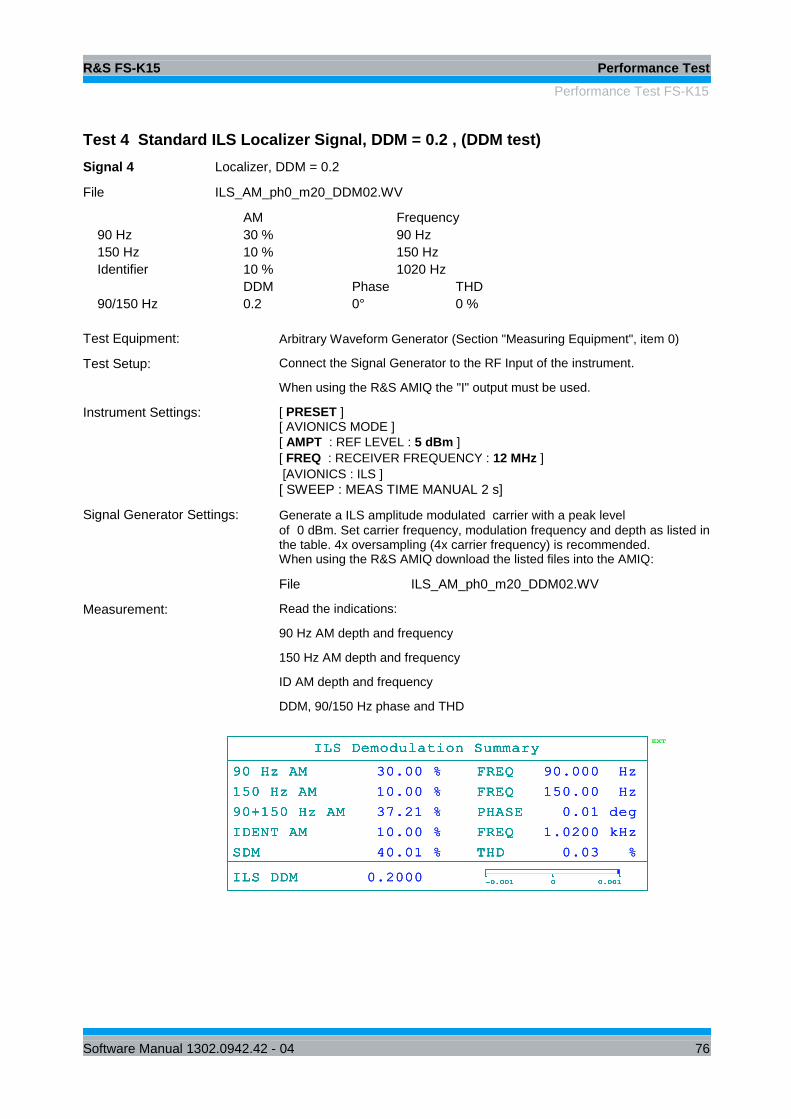
R&S FS-K15 Performance Test
Performance Test FS-K15
Software Manual 1302.0942.42 - 04 76
Test 4 Standard ILS Localizer Signal, DDM = 0.2 , (DDM test)
Signal 4 Localizer, DDM = 0.2
File ILS_AM_ph0_m20_DDM02.WV
AM Frequency
90 Hz 30 % 90 Hz
150 Hz 10 % 150 Hz
Identifier 10 % 1020 Hz
DDM Phase THD
90/150 Hz 0.2 0° 0 %
Test Equipment: Arbitrary Waveform Generator (Section "Measuring Equipment", item 0)
Test Setup: Connect the Signal Generator to the RF Input of the instrument.
When using the R&S AMIQ the "I" output must be used.
Instrument Settings:
[ PRESET ] [ AVIONICS MODE ]
[ AMPT : REF LEVEL : 5 dBm ]
[ FREQ : RECEIVER FREQUENCY : 12 MHz ]
[AVIONICS : ILS ]
[ SWEEP : MEAS TIME MANUAL 2 s]
Signal Generator Settings: Generate a ILS amplitude modulated carrier with a peak level
of 0 dBm. Set carrier frequency, modulation frequency and depth as listed in the table. 4x oversampling (4x carrier frequency) is recommended. When using the R&S AMIQ download the listed files into the AMIQ:
File ILS_AM_ph0_m20_DDM02.WV
Measurement: Read the indications:
90 Hz AM depth and frequency
150 Hz AM depth and frequency
ID AM depth and frequency
DDM, 90/150 Hz phase and THD
A
DBW 12.5 kHz
RBW 3.8 Hz
AQT 1 s
EXT
Att 20 dB
ILS Demodulation Summary
90 Hz AM FREQ
150 Hz AM FREQ
90+150 Hz AM PHASE
IDENT AM FREQ
SDM THD
ILS DDM-0.001 0 0.001
-95 -85 -75 -65 -55 -45 -35 -25 -15 -5 5
RF LEVEL
RF FREQUENCY
Tuned Frequency 12.0000000 MHz
Carrier Offset
12.0000000 MHz
0.950 dBm
11.964 mHz
12.0000000 MHz
0.950 dBm
11.964 mHz
ILS Demodulation Summary
90 Hz AM FREQ
150 Hz AM FREQ
90+150 Hz AM PHASE
IDENT AM FREQ
SDM THD
ILS DDM-0.001 0 0.001
30.00 % 90.000 Hz
10.00 % 150.00 Hz
37.21 % 0.01 deg
10.00 % 1.0200 kHz
40.01 % 0.03 %
0.2000
-95 -85 -75 -65 -55 -45 -35 -25 -15 -5 5
RF LEVEL
RF FREQUENCY
Tuned Frequency 12.0000000 MHz
Carrier Offset
12.0000000 MHz
0.950 dBm
11.964 mHz
12.0000000 MHz
0.950 dBm
11.964 mHz
ILS Demodulation Summary
90 Hz AM FREQ
150 Hz AM FREQ
90+150 Hz AM PHASE
IDENT AM FREQ
SDM THD
ILS DDM-0.001 0 0.001
-95 -85 -75 -65 -55 -45 -35 -25 -15 -5 5
RF LEVEL
RF FREQUENCY
Tuned Frequency 12.0000000 MHz
Carrier Offset
12.0000000 MHz
0.950 dBm
11.964 mHz
12.0000000 MHz
0.950 dBm
11.964 mHz
ILS Demodulation Summary
90 Hz AM FREQ
150 Hz AM FREQ
90+150 Hz AM PHASE
IDENT AM FREQ
SDM THD
ILS DDM-0.001 0 0.001
30.00 % 90.000 Hz
10.00 % 150.00 Hz
37.21 % 0.01 deg
10.00 % 1.0200 kHz
40.01 % 0.03 %
0.2000
-95 -85 -75 -65 -55 -45 -35 -25 -15 -5 5
RF LEVEL
RF FREQUENCY
Tuned Frequency 12.0000000 MHz
Carrier Offset
12.0000000 MHz
0.950 dBm
11.964 mHz
12.0000000 MHz
0.950 dBm
11.964 mHz
Date: 11.DEC.2007 13:38:07

R&S FS-K15 Performance Test
Performance Test FS-K15
Software Manual 1302.0942.42 - 04 77
Test 5 ILS Localizer Signal, DDM = -0.2 , Phase = -30° (DDM test at different phase)
Signal 5 Localizer, DDM = -0.2, phase = -30°
File ILS_AM_ph-30_m20_DDM-02.WV
AM Frequency
90 Hz 10 % 90 Hz
150 Hz 30 % 150 Hz
Identifier 10 % 1020 Hz
DDM Phase THD
90/150 Hz -0.2 -30° 0 %
Test Equipment: Arbitrary Waveform Generator (Section "Measuring Equipment", item 0)
Test Setup: Connect the Signal Generator to the RF Input of the instrument.
When using the R&S AMIQ the "I" output must be used.
Instrument Settings:
[ PRESET ] [ AVIONICS MODE ]
[ AMPT : REF LEVEL : 5 dBm ]
[ FREQ : RECEIVER FREQUENCY : 12 MHz ]
[AVIONICS : ILS ]
[ SWEEP : MEAS TIME MANUAL 2 s]
Signal Generator Settings: Generate a ILS amplitude modulated carrier with a peak level
of 0 dBm. Set carrier frequency, modulation frequency and depth as listed in the table. 4x oversampling (4x carrier frequency) is recommended. When using the R&S AMIQ download the listed files into the AMIQ:
File ILS_AM_ph-30_m20_DDM-02.WV
Measurement: Read the indications:
90 Hz AM depth and frequency
150 Hz AM depth and frequency
ID AM depth and frequency
DDM, 90/150 Hz phase and THD
A
DBW 12.5 kHz
RBW 3.8 Hz
AQT 1 s
EXT
Att 20 dB
ILS Demodulation Summary
90 Hz AM FREQ
150 Hz AM FREQ
90+150 Hz AM PHASE
IDENT AM FREQ
SDM THD
ILS DDM-0.001 0 0.001
-95 -85 -75 -65 -55 -45 -35 -25 -15 -5 5
RF LEVEL
RF FREQUENCY
Tuned Frequency 12.0000000 MHz
Carrier Offset
12.0000000 MHz
0.823 dBm
10.993 mHz
12.0000000 MHz
0.823 dBm
10.993 mHz
ILS Demodulation Summary
90 Hz AM FREQ
150 Hz AM FREQ
90+150 Hz AM PHASE
IDENT AM FREQ
SDM THD
ILS DDM-0.001 0 0.001
10.00 % 90.000 Hz
30.00 % 150.00 Hz
39.57 % -30.00 deg
10.00 % 1.0200 kHz
40.01 % 0.04 %
-0.2000
-95 -85 -75 -65 -55 -45 -35 -25 -15 -5 5
RF LEVEL
RF FREQUENCY
Tuned Frequency 12.0000000 MHz
Carrier Offset
12.0000000 MHz
0.823 dBm
10.993 mHz
12.0000000 MHz
0.823 dBm
10.993 mHz
ILS Demodulation Summary
90 Hz AM FREQ
150 Hz AM FREQ
90+150 Hz AM PHASE
IDENT AM FREQ
SDM THD
ILS DDM-0.001 0 0.001
-95 -85 -75 -65 -55 -45 -35 -25 -15 -5 5
RF LEVEL
RF FREQUENCY
Tuned Frequency 12.0000000 MHz
Carrier Offset
12.0000000 MHz
0.823 dBm
10.993 mHz
12.0000000 MHz
0.823 dBm
10.993 mHz
ILS Demodulation Summary
90 Hz AM FREQ
150 Hz AM FREQ
90+150 Hz AM PHASE
IDENT AM FREQ
SDM THD
ILS DDM-0.001 0 0.001
10.00 % 90.000 Hz
30.00 % 150.00 Hz
39.57 % -30.00 deg
10.00 % 1.0200 kHz
40.01 % 0.04 %
-0.2000
-95 -85 -75 -65 -55 -45 -35 -25 -15 -5 5
RF LEVEL
RF FREQUENCY
Tuned Frequency 12.0000000 MHz
Carrier Offset
12.0000000 MHz
0.823 dBm
10.993 mHz
12.0000000 MHz
0.823 dBm
10.993 mHz
Date: 11.DEC.2007 13:41:05
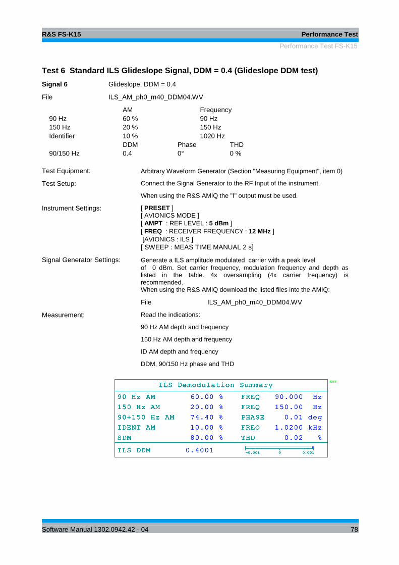
R&S FS-K15 Performance Test
Performance Test FS-K15
Software Manual 1302.0942.42 - 04 78
Test 6 Standard ILS Glideslope Signal, DDM = 0.4 (Glideslope DDM test)
Signal 6 Glideslope, DDM = 0.4
File ILS_AM_ph0_m40_DDM04.WV
AM Frequency
90 Hz 60 % 90 Hz
150 Hz 20 % 150 Hz
Identifier 10 % 1020 Hz
DDM Phase THD
90/150 Hz 0.4 0° 0 %
Test Equipment: Arbitrary Waveform Generator (Section "Measuring Equipment", item 0)
Test Setup: Connect the Signal Generator to the RF Input of the instrument.
When using the R&S AMIQ the "I" output must be used.
Instrument Settings:
[ PRESET ] [ AVIONICS MODE ]
[ AMPT : REF LEVEL : 5 dBm ]
[ FREQ : RECEIVER FREQUENCY : 12 MHz ]
[AVIONICS : ILS ]
[ SWEEP : MEAS TIME MANUAL 2 s]
Signal Generator Settings: Generate a ILS amplitude modulated carrier with a peak level
of 0 dBm. Set carrier frequency, modulation frequency and depth as listed in the table. 4x oversampling (4x carrier frequency) is recommended. When using the R&S AMIQ download the listed files into the AMIQ:
File ILS_AM_ph0_m40_DDM04.WV
Measurement: Read the indications:
90 Hz AM depth and frequency
150 Hz AM depth and frequency
ID AM depth and frequency
DDM, 90/150 Hz phase and THD
A
DBW 12.5 kHz
RBW 3.8 Hz
AQT 1 s
EXT
Att 20 dB
ILS Demodulation Summary
90 Hz AM FREQ
150 Hz AM FREQ
90+150 Hz AM PHASE
IDENT AM FREQ
SDM THD
ILS DDM-0.001 0 0.001
-95 -85 -75 -65 -55 -45 -35 -25 -15 -5 5
RF LEVEL
RF FREQUENCY
Tuned Frequency 12.0000000 MHz
Carrier Offset
12.0000000 MHz
-0.431 dBm
10.859 mHz
12.0000000 MHz
-0.431 dBm
10.859 mHz
ILS Demodulation Summary
90 Hz AM FREQ
150 Hz AM FREQ
90+150 Hz AM PHASE
IDENT AM FREQ
SDM THD
ILS DDM-0.001 0 0.001
60.00 % 90.000 Hz
20.00 % 150.00 Hz
74.40 % 0.01 deg
10.00 % 1.0200 kHz
80.00 % 0.02 %
0.4001
-95 -85 -75 -65 -55 -45 -35 -25 -15 -5 5
RF LEVEL
RF FREQUENCY
Tuned Frequency 12.0000000 MHz
Carrier Offset
12.0000000 MHz
-0.431 dBm
10.859 mHz
12.0000000 MHz
-0.431 dBm
10.859 mHz
ILS Demodulation Summary
90 Hz AM FREQ
150 Hz AM FREQ
90+150 Hz AM PHASE
IDENT AM FREQ
SDM THD
ILS DDM-0.001 0 0.001
-95 -85 -75 -65 -55 -45 -35 -25 -15 -5 5
RF LEVEL
RF FREQUENCY
Tuned Frequency 12.0000000 MHz
Carrier Offset
12.0000000 MHz
-0.431 dBm
10.859 mHz
12.0000000 MHz
-0.431 dBm
10.859 mHz
ILS Demodulation Summary
90 Hz AM FREQ
150 Hz AM FREQ
90+150 Hz AM PHASE
IDENT AM FREQ
SDM THD
ILS DDM-0.001 0 0.001
60.00 % 90.000 Hz
20.00 % 150.00 Hz
74.40 % 0.01 deg
10.00 % 1.0200 kHz
80.00 % 0.02 %
0.4001
-95 -85 -75 -65 -55 -45 -35 -25 -15 -5 5
RF LEVEL
RF FREQUENCY
Tuned Frequency 12.0000000 MHz
Carrier Offset
12.0000000 MHz
-0.431 dBm
10.859 mHz
12.0000000 MHz
-0.431 dBm
10.859 mHz
Date: 11.DEC.2007 13:49:45

R&S FS-K15 Performance Test
Performance Test FS-K15
Software Manual 1302.0942.42 - 04 79
Test 7 ILS Glideslope Signal, DDM = -0.4 , Phase = 59° , Frequency offset 1%
Signal 7 Glideslope, DDM = -0.4, Frequency offset +1%, Phase 59°
Receiver Frequency = 12.12 MHz !
File ILS_AM_ph59_m40_DDM-04_offset01.WV
AM Frequency
90 Hz 20 % 90.9 Hz
150 Hz 60 % 151.5 Hz
Identifier 10 % 1030.2 Hz
DDM Phase THD
90/150 Hz -0.4 59° 0 %
Test Equipment: Arbitrary Waveform Generator (Section "Measuring Equipment", item 0)
Test Setup: Connect the Signal Generator to the RF Input of the instrument.
When using the R&S AMIQ the "I" output must be used.
Instrument Settings:
[ PRESET ] [ AVIONICS MODE ]
[ AMPT : REF LEVEL : 5 dBm ]
[ FREQ : RECEIVER FREQUENCY : 12.12 MHz ]
[AVIONICS : ILS ]
[ SWEEP : MEAS TIME MANUAL 2 s]
Signal Generator Settings: Generate a ILS amplitude modulated carrier with a peak level
of 0 dBm. Set carrier frequency, modulation frequency and depth as listed in the table. 4x oversampling (4x carrier frequency) is recommended. When using the R&S AMIQ download the listed files into the AMIQ:
File ILS_AM_ph59_m40_DDM-04_offset01.WV
Measurement: Read the indications:
90 Hz AM depth and frequency, 150 Hz AM depth and frequency
ID AM depth and frequency, DDM, 90/150 Hz phase and THD
A
Att 20 dB
EXT
DBW 12.5 kHz
RBW 3.8 Hz
AQT 1 s
ILS Demodulation Summary
90 Hz AM FREQ
150 Hz AM FREQ
90+150 Hz AM PHASE
IDENT AM FREQ
SDM THD
ILS DDM-0.001 0 0.001
-95 -85 -75 -65 -55 -45 -35 -25 -15 -5 5
RF LEVEL
RF FREQUENCY
Tuned Frequency 12.1200000 MHz
Carrier Offset
12.1200000 MHz
-0.655 dBm
15.180 mHz
12.1200000 MHz
-0.655 dBm
15.180 mHz
ILS Demodulation Summary
90 Hz AM FREQ
150 Hz AM FREQ
90+150 Hz AM PHASE
IDENT AM FREQ
SDM THD
ILS DDM-0.001 0 0.001
19.99 % 90.900 Hz
59.97 % 151.50 Hz
79.95 % 58.98 deg
10.00 % 1.0302 kHz
79.96 % 0.02 %
-0.3998
-95 -85 -75 -65 -55 -45 -35 -25 -15 -5 5
RF LEVEL
RF FREQUENCY
Tuned Frequency 12.1200000 MHz
Carrier Offset
12.1200000 MHz
-0.655 dBm
15.180 mHz
12.1200000 MHz
-0.655 dBm
15.180 mHz
ILS Demodulation Summary
90 Hz AM FREQ
150 Hz AM FREQ
90+150 Hz AM PHASE
IDENT AM FREQ
SDM THD
ILS DDM-0.001 0 0.001
-95 -85 -75 -65 -55 -45 -35 -25 -15 -5 5
RF LEVEL
RF FREQUENCY
Tuned Frequency 12.1200000 MHz
Carrier Offset
12.1200000 MHz
-0.655 dBm
15.180 mHz
12.1200000 MHz
-0.655 dBm
15.180 mHz
ILS Demodulation Summary
90 Hz AM FREQ
150 Hz AM FREQ
90+150 Hz AM PHASE
IDENT AM FREQ
SDM THD
ILS DDM-0.001 0 0.001
19.99 % 90.900 Hz
59.97 % 151.50 Hz
79.95 % 58.98 deg
10.00 % 1.0302 kHz
79.96 % 0.02 %
-0.3998
-95 -85 -75 -65 -55 -45 -35 -25 -15 -5 5
RF LEVEL
RF FREQUENCY
Tuned Frequency 12.1200000 MHz
Carrier Offset
12.1200000 MHz
-0.655 dBm
15.180 mHz
12.1200000 MHz
-0.655 dBm
15.180 mHz
Date: 11.DEC.2007 14:15:33

R&S FS-K15 Performance Test
Performance Test FS-K15
Software Manual 1302.0942.42 - 04 80
4.3.2 Checking the VOR Demodulation (AM, FM)
The test of the VOR demodulator is performed on several test signals with variation of
the following parameters:
Modulation depth = 10% to 40 % (30 Hz, 9.96 kHz), Freq(ID) = 300 Hz to 3990 Hz (to
test the full bandwidth of the identifier channel), 9.96 kHz carrier with frequency
deviation = 200 to 700 Hz, VOR phase 0 to 360°, modulation frequency +1% (to test
the selectivity).
Test 1 Standard VOR Signal, VOR phase = 0°, no distortion
Signal 1 Standard VOR
File VOR_AM_ph0_m30_dev480.WV
AM (depth) Frequency
30 Hz 30 % 30 Hz
9960 Hz 30 % 9960 Hz
Identifier 10 % 1020 Hz
9960 Hz FM (deviation) 480 Hz
30/30 Hz Azimuth 0°
Test Equipment: Arbitrary Waveform Generator (Section "Measuring Equipment", item 0)
Test Setup: Connect the Signal Generator to the RF Input of the instrument.
When using the R&S AMIQ the "I" output must be used.
Instrument Settings:
[ PRESET ] [ AVIONICS MODE ]
[ AMPT : REF LEVEL : 5 dBm ]
[ FREQ : RECEIVER FREQUENCY : 12 MHz ]
[AVIONICS : VOR ]
[ SWEEP : MEAS TIME MANUAL 2 s]
Signal Generator Settings: Generate a VOR amplitude modulated carrier with a peak level of 0 dBm.
Set carrier frequency, modulation frequency and depth as listed in the table.
4x oversampling (4x carrier frequency) is recommended.
When using the R&S AMIQ download the listed files into the AMIQ:
File VOR_AM_ph0_m30_dev480.WV
Measurement: Read the indications:
30 Hz AM depth and frequency, 9.96 kHz AM depth and frequency
30 Hz FM deviation and frequency, ID AM depth and frequency
VOR Phase
A
DBW 25 kHz
RBW 3.8 Hz
AQT 1 sAtt 20 dB
EXT
VOR Demodulation Summary
30 Hz AM FREQ
9.96 kHz AM FREQ
30 Hz FM FREQ
IDENT AM FREQ
VOR PHASE0 180 360
-95 -85 -75 -65 -55 -45 -35 -25 -15 -5 5
RF LEVEL
RF FREQUENCY
Tuned Frequency 12.0000000 MHz
Carrier Offset
12.0000000 MHz
-0.156 dBm
12.782 mHz
12.0000000 MHz
-0.156 dBm
12.782 mHz
VOR Demodulation Summary
30 Hz AM FREQ
9.96 kHz AM FREQ
30 Hz FM FREQ
IDENT AM FREQ
VOR PHASE0 180 360
30.00 % 30.000 Hz
30.01 % 9.9600 kHz
480.01 Hz 30.000 Hz
10.00 % 1.0200 kHz
0.02 deg
-95 -85 -75 -65 -55 -45 -35 -25 -15 -5 5
RF LEVEL
RF FREQUENCY
Tuned Frequency 12.0000000 MHz
Carrier Offset
12.0000000 MHz
-0.156 dBm
12.782 mHz
12.0000000 MHz
-0.156 dBm
12.782 mHz
VOR Demodulation Summary
30 Hz AM FREQ
9.96 kHz AM FREQ
30 Hz FM FREQ
IDENT AM FREQ
VOR PHASE0 180 360
-95 -85 -75 -65 -55 -45 -35 -25 -15 -5 5
RF LEVEL
RF FREQUENCY
Tuned Frequency 12.0000000 MHz
Carrier Offset
12.0000000 MHz
-0.156 dBm
12.782 mHz
12.0000000 MHz
-0.156 dBm
12.782 mHz
VOR Demodulation Summary
30 Hz AM FREQ
9.96 kHz AM FREQ
30 Hz FM FREQ
IDENT AM FREQ
VOR PHASE0 180 360
30.00 % 30.000 Hz
30.01 % 9.9600 kHz
480.01 Hz 30.000 Hz
10.00 % 1.0200 kHz
0.02 deg
-95 -85 -75 -65 -55 -45 -35 -25 -15 -5 5
RF LEVEL
RF FREQUENCY
Tuned Frequency 12.0000000 MHz
Carrier Offset
12.0000000 MHz
-0.156 dBm
12.782 mHz
12.0000000 MHz
-0.156 dBm
12.782 mHz
Date: 12.DEC.2007 12:07:10

R&S FS-K15 Performance Test
Performance Test FS-K15
Software Manual 1302.0942.42 - 04 81
Test 2 VOR Signal, low AM depth, Freq(ID) 300 Hz, ID low frequency test
Signal 2 m = 10%, frequency(Id) = 300 Hz
File VOR_AM_ph0_m10_dev480_fid03.WV
AM (depth) Frequency
30 Hz 10 % 30 Hz
9960 Hz 10 % 9960 Hz
Identifier 10 % 300 Hz
9960 Hz FM (deviation) 480 Hz
30/30 Hz Azimuth 0°
Test Equipment: Arbitrary Waveform Generator (Section "Measuring Equipment", item 0)
Test Setup: Connect the Signal Generator to the RF Input of the instrument.
When using the R&S AMIQ the "I" output must be used.
Instrument Settings:
[ PRESET ] [ AVIONICS MODE ]
[ AMPT : REF LEVEL : 5 dBm ]
[ FREQ : RECEIVER FREQUENCY : 12 MHz ]
[AVIONICS : VOR ]
[ SWEEP : MEAS TIME MANUAL 2 s]
Signal Generator Settings: Generate a VOR amplitude modulated carrier with a peak level of 0 dBm.
Set carrier frequency, modulation frequency and depth as listed in the table.
4x oversampling (4x carrier frequency) is recommended.
When using the R&S AMIQ download the listed files into the AMIQ:
File VOR_AM_ph0_m10_dev480_fid03.WV
Measurement: Read the indications:
30 Hz AM depth and frequency
9.96 kHz AM depth and frequency
30 Hz FM deviation and frequency
ID AM depth and frequency
VOR Phase, THD (30)
A
DBW 25 kHz
RBW 3.8 Hz
AQT 1 sAtt 20 dB
EXT
VOR Demodulation Summary
30 Hz AM FREQ
9.96 kHz AM FREQ
30 Hz FM FREQ
IDENT AM FREQ
VOR PHASE0 180 360
-95 -85 -75 -65 -55 -45 -35 -25 -15 -5 5
RF LEVEL
RF FREQUENCY
Tuned Frequency 12.0000000 MHz
Carrier Offset
12.0000000 MHz
1.848 dBm
10.733 mHz
12.0000000 MHz
1.848 dBm
10.733 mHz
VOR Demodulation Summary
30 Hz AM FREQ
9.96 kHz AM FREQ
30 Hz FM FREQ
IDENT AM FREQ
VOR PHASE0 180 360
10.00 % 30.000 Hz
10.00 % 9.9600 kHz
479.99 Hz 30.000 Hz
10.00 % 299.99 Hz
0.02 deg
-95 -85 -75 -65 -55 -45 -35 -25 -15 -5 5
RF LEVEL
RF FREQUENCY
Tuned Frequency 12.0000000 MHz
Carrier Offset
12.0000000 MHz
1.848 dBm
10.733 mHz
12.0000000 MHz
1.848 dBm
10.733 mHz
VOR Demodulation Summary
30 Hz AM FREQ
9.96 kHz AM FREQ
30 Hz FM FREQ
IDENT AM FREQ
VOR PHASE0 180 360
-95 -85 -75 -65 -55 -45 -35 -25 -15 -5 5
RF LEVEL
RF FREQUENCY
Tuned Frequency 12.0000000 MHz
Carrier Offset
12.0000000 MHz
1.848 dBm
10.733 mHz
12.0000000 MHz
1.848 dBm
10.733 mHz
VOR Demodulation Summary
30 Hz AM FREQ
9.96 kHz AM FREQ
30 Hz FM FREQ
IDENT AM FREQ
VOR PHASE0 180 360
10.00 % 30.000 Hz
10.00 % 9.9600 kHz
479.99 Hz 30.000 Hz
10.00 % 299.99 Hz
0.02 deg
-95 -85 -75 -65 -55 -45 -35 -25 -15 -5 5
RF LEVEL
RF FREQUENCY
Tuned Frequency 12.0000000 MHz
Carrier Offset
12.0000000 MHz
1.848 dBm
10.733 mHz
12.0000000 MHz
1.848 dBm
10.733 mHz
Date: 12.DEC.2007 12:26:39
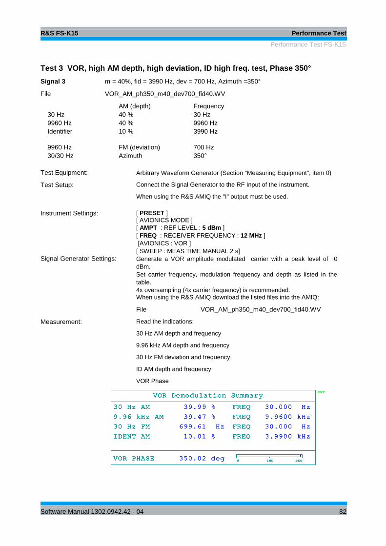
R&S FS-K15 Performance Test
Performance Test FS-K15
Software Manual 1302.0942.42 - 04 82
Test 3 VOR, high AM depth, high deviation, ID high freq. test, Phase 350°
Signal 3 m = 40%, fid = 3990 Hz, dev = 700 Hz, Azimuth =350°
File VOR_AM_ph350_m40_dev700_fid40.WV
AM (depth) Frequency
30 Hz 40 % 30 Hz
9960 Hz 40 % 9960 Hz
Identifier 10 % 3990 Hz
9960 Hz FM (deviation) 700 Hz
30/30 Hz Azimuth 350°
Test Equipment: Arbitrary Waveform Generator (Section "Measuring Equipment", item 0)
Test Setup: Connect the Signal Generator to the RF Input of the instrument.
When using the R&S AMIQ the "I" output must be used.
Instrument Settings:
[ PRESET ] [ AVIONICS MODE ]
[ AMPT : REF LEVEL : 5 dBm ]
[ FREQ : RECEIVER FREQUENCY : 12 MHz ]
[AVIONICS : VOR ]
[ SWEEP : MEAS TIME MANUAL 2 s]
Signal Generator Settings: Generate a VOR amplitude modulated carrier with a peak level of 0
dBm.
Set carrier frequency, modulation frequency and depth as listed in the
table.
4x oversampling (4x carrier frequency) is recommended.
When using the R&S AMIQ download the listed files into the AMIQ:
File VOR_AM_ph350_m40_dev700_fid40.WV
Measurement: Read the indications:
30 Hz AM depth and frequency
9.96 kHz AM depth and frequency
30 Hz FM deviation and frequency,
ID AM depth and frequency
VOR Phase
A
DBW 25 kHz
RBW 3.8 Hz
AQT 1 sAtt 20 dB
EXT
VOR Demodulation Summary
30 Hz AM FREQ
9.96 kHz AM FREQ
30 Hz FM FREQ
IDENT AM FREQ
VOR PHASE0 180 360
-95 -85 -75 -65 -55 -45 -35 -25 -15 -5 5
RF LEVEL
RF FREQUENCY
Tuned Frequency 12.0000000 MHz
Carrier Offset
12.0000000 MHz
-0.853 dBm
11.521 mHz
12.0000000 MHz
-0.853 dBm
11.521 mHz
VOR Demodulation Summary
30 Hz AM FREQ
9.96 kHz AM FREQ
30 Hz FM FREQ
IDENT AM FREQ
VOR PHASE0 180 360
39.99 % 30.000 Hz
39.47 % 9.9600 kHz
699.61 Hz 30.000 Hz
10.01 % 3.9900 kHz
350.02 deg
-95 -85 -75 -65 -55 -45 -35 -25 -15 -5 5
RF LEVEL
RF FREQUENCY
Tuned Frequency 12.0000000 MHz
Carrier Offset
12.0000000 MHz
-0.853 dBm
11.521 mHz
12.0000000 MHz
-0.853 dBm
11.521 mHz
VOR Demodulation Summary
30 Hz AM FREQ
9.96 kHz AM FREQ
30 Hz FM FREQ
IDENT AM FREQ
VOR PHASE0 180 360
-95 -85 -75 -65 -55 -45 -35 -25 -15 -5 5
RF LEVEL
RF FREQUENCY
Tuned Frequency 12.0000000 MHz
Carrier Offset
12.0000000 MHz
-0.853 dBm
11.521 mHz
12.0000000 MHz
-0.853 dBm
11.521 mHz
VOR Demodulation Summary
30 Hz AM FREQ
9.96 kHz AM FREQ
30 Hz FM FREQ
IDENT AM FREQ
VOR PHASE0 180 360
39.99 % 30.000 Hz
39.47 % 9.9600 kHz
699.61 Hz 30.000 Hz
10.01 % 3.9900 kHz
350.02 deg
-95 -85 -75 -65 -55 -45 -35 -25 -15 -5 5
RF LEVEL
RF FREQUENCY
Tuned Frequency 12.0000000 MHz
Carrier Offset
12.0000000 MHz
-0.853 dBm
11.521 mHz
12.0000000 MHz
-0.853 dBm
11.521 mHz
Date: 12.DEC.2007 12:32:04

R&S FS-K15 Performance Test
Performance Test FS-K15
Software Manual 1302.0942.42 - 04 83
Test 4 Standard VOR Signal, VOR phase = 45°, no distortion
Signal 4 Azimuth = 45°
File VOR_AM_ph45_m30_dev480.WV
AM (depth) Frequency
30 Hz 30 % 30 Hz
9960 Hz 30 % 9960 Hz
Identifier 10 % 1020 Hz
9960 Hz FM (deviation) 480 Hz
30/30 Hz Azimuth 45°
Test Equipment: Arbitrary Waveform Generator (Section "Measuring Equipment", item 0)
Test Setup: Connect the Signal Generator to the RF Input of the instrument.
When using the R&S AMIQ the "I" output must be used.
Instrument Settings:
[ PRESET ] [ AVIONICS MODE ]
[ AMPT : REF LEVEL : 5 dBm ]
[ FREQ : RECEIVER FREQUENCY : 12 MHz ]
[AVIONICS : VOR ]
[ SWEEP : MEAS TIME MANUAL 2 s]
Signal Generator Settings: Generate a VOR amplitude modulated carrier with a peak level of 0 dBm.
Set carrier frequency, modulation frequency and depth as listed in the table.
4x oversampling (4x carrier frequency) is recommended.
When using the R&S AMIQ download the listed files into the AMIQ:
File VOR_AM_ph45_m30_dev480.WV
Measurement: Read the indications:
30 Hz AM depth and frequency
9.96 kHz AM depth and frequency
30 Hz FM deviation and frequency
ID AM depth and frequency
VOR Phase
A
DBW 25 kHz
RBW 3.8 Hz
AQT 1 sAtt 20 dB
EXT
VOR Demodulation Summary
30 Hz AM FREQ
9.96 kHz AM FREQ
30 Hz FM FREQ
IDENT AM FREQ
VOR PHASE0 180 360
-95 -85 -75 -65 -55 -45 -35 -25 -15 -5 5
RF LEVEL
RF FREQUENCY
Tuned Frequency 12.0000000 MHz
Carrier Offset
12.0000000 MHz
-0.155 dBm
10.702 mHz
12.0000000 MHz
-0.155 dBm
10.702 mHz
VOR Demodulation Summary
30 Hz AM FREQ
9.96 kHz AM FREQ
30 Hz FM FREQ
IDENT AM FREQ
VOR PHASE0 180 360
30.00 % 30.000 Hz
30.01 % 9.9600 kHz
479.98 Hz 30.002 Hz
10.00 % 1.0200 kHz
45.01 deg
-95 -85 -75 -65 -55 -45 -35 -25 -15 -5 5
RF LEVEL
RF FREQUENCY
Tuned Frequency 12.0000000 MHz
Carrier Offset
12.0000000 MHz
-0.155 dBm
10.702 mHz
12.0000000 MHz
-0.155 dBm
10.702 mHz
VOR Demodulation Summary
30 Hz AM FREQ
9.96 kHz AM FREQ
30 Hz FM FREQ
IDENT AM FREQ
VOR PHASE0 180 360
-95 -85 -75 -65 -55 -45 -35 -25 -15 -5 5
RF LEVEL
RF FREQUENCY
Tuned Frequency 12.0000000 MHz
Carrier Offset
12.0000000 MHz
-0.155 dBm
10.702 mHz
12.0000000 MHz
-0.155 dBm
10.702 mHz
VOR Demodulation Summary
30 Hz AM FREQ
9.96 kHz AM FREQ
30 Hz FM FREQ
IDENT AM FREQ
VOR PHASE0 180 360
30.00 % 30.000 Hz
30.01 % 9.9600 kHz
479.98 Hz 30.002 Hz
10.00 % 1.0200 kHz
45.01 deg
-95 -85 -75 -65 -55 -45 -35 -25 -15 -5 5
RF LEVEL
RF FREQUENCY
Tuned Frequency 12.0000000 MHz
Carrier Offset
12.0000000 MHz
-0.155 dBm
10.702 mHz
12.0000000 MHz
-0.155 dBm
10.702 mHz
Date: 12.DEC.2007 13:46:47

R&S FS-K15 Performance Test
Performance Test FS-K15
Software Manual 1302.0942.42 - 04 84
Test 5 VOR Signal, VOR phase = 271°, low deviation (200 Hz)
Signal 5 Azimuth = 271°, Deviation 200 Hz
File VOR_AM_ph271_m30_dev200.WV
AM (depth) Frequency
30 Hz 30 % 30 Hz
9960 Hz 30 % 9960 Hz
Identifier 10 % 1020 Hz
9960 Hz FM (deviation) 200 Hz
30/30 Hz Azimuth 271°
Test Equipment: Arbitrary Waveform Generator (Section "Measuring Equipment", item 0)
Test Setup: Connect the Signal Generator to the RF Input of the instrument.
When using the R&S AMIQ the "I" output must be used.
Instrument Settings:
[ PRESET ] [ AVIONICS MODE ]
[ AMPT : REF LEVEL : 5 dBm ]
[ FREQ : RECEIVER FREQUENCY : 12 MHz ]
[AVIONICS : VOR ]
[ SWEEP : MEAS TIME MANUAL 2 s]
Signal Generator Settings: Generate a VOR amplitude modulated carrier with a peak level of 0 dBm.
Set carrier frequency, modulation frequency and depth as listed in the table.
4x oversampling (4x carrier frequency) is recommended.
When using the R&S AMIQ download the listed files into the AMIQ:
File VOR_AM_ph271_m30_dev200.WV
Measurement: Read the indications:
30 Hz AM depth and frequency
9.96 kHz AM depth and frequency
30 Hz FM deviation and frequency
ID AM depth and frequency
VOR Phase
A
DBW 25 kHz
RBW 3.8 Hz
AQT 1 sAtt 20 dB
EXT
VOR Demodulation Summary
30 Hz AM FREQ
9.96 kHz AM FREQ
30 Hz FM FREQ
IDENT AM FREQ
VOR PHASE0 180 360
-95 -85 -75 -65 -55 -45 -35 -25 -15 -5 5
RF LEVEL
RF FREQUENCY
Tuned Frequency 12.0000000 MHz
Carrier Offset
12.0000000 MHz
-0.158 dBm
11.793 mHz
12.0000000 MHz
-0.158 dBm
11.793 mHz
VOR Demodulation Summary
30 Hz AM FREQ
9.96 kHz AM FREQ
30 Hz FM FREQ
IDENT AM FREQ
VOR PHASE0 180 360
30.00 % 30.000 Hz
30.01 % 9.9600 kHz
199.98 Hz 30.004 Hz
10.00 % 1.0200 kHz
271.01 deg
-95 -85 -75 -65 -55 -45 -35 -25 -15 -5 5
RF LEVEL
RF FREQUENCY
Tuned Frequency 12.0000000 MHz
Carrier Offset
12.0000000 MHz
-0.158 dBm
11.793 mHz
12.0000000 MHz
-0.158 dBm
11.793 mHz
VOR Demodulation Summary
30 Hz AM FREQ
9.96 kHz AM FREQ
30 Hz FM FREQ
IDENT AM FREQ
VOR PHASE0 180 360
-95 -85 -75 -65 -55 -45 -35 -25 -15 -5 5
RF LEVEL
RF FREQUENCY
Tuned Frequency 12.0000000 MHz
Carrier Offset
12.0000000 MHz
-0.158 dBm
11.793 mHz
12.0000000 MHz
-0.158 dBm
11.793 mHz
VOR Demodulation Summary
30 Hz AM FREQ
9.96 kHz AM FREQ
30 Hz FM FREQ
IDENT AM FREQ
VOR PHASE0 180 360
30.00 % 30.000 Hz
30.01 % 9.9600 kHz
199.98 Hz 30.004 Hz
10.00 % 1.0200 kHz
271.01 deg
-95 -85 -75 -65 -55 -45 -35 -25 -15 -5 5
RF LEVEL
RF FREQUENCY
Tuned Frequency 12.0000000 MHz
Carrier Offset
12.0000000 MHz
-0.158 dBm
11.793 mHz
12.0000000 MHz
-0.158 dBm
11.793 mHz
Date: 12.DEC.2007 13:52:14

R&S FS-K15 Performance Test
Performance Test FS-K15
Software Manual 1302.0942.42 - 04 85
Test 6 VOR Signal, VOR phase = 180.1°, frequency offset 1%
Signal 6 Azimuth = 180.1°, Frequency offset +1%
Receiver Frequency = 12.12 MHz
File VOR_AM_ph180_m30_dev480_offset01.WV
AM (depth) Frequency
30 Hz 30 % 30.3 Hz
9960 Hz 30 % 10059.6 Hz
Identifier 10 % 1030.2 Hz
9960 Hz FM (deviation) 480 Hz
30/30 Hz Azimuth 180.1°
Test Equipment: Arbitrary Waveform Generator (Section "Measuring Equipment", item 0)
Test Setup: Connect the Signal Generator to the RF Input of the instrument.
When using the R&S AMIQ the "I" output must be used.
Instrument Settings:
[ PRESET ] [ AVIONICS MODE ]
[ AMPT : REF LEVEL : 5 dBm ]
[ FREQ : RECEIVER FREQUENCY : 12 MHz ]
[AVIONICS : VOR ]
[ SWEEP : MEAS TIME MANUAL 2 s]
Signal Generator Settings:
Generate a VOR amplitude modulated carrier with a peak level of 0 dBm.
Set carrier frequency, modulation frequency and depth as listed in the table.
4x oversampling (4x carrier frequency) is recommended.
When using the R&S AMIQ download the listed files into the AMIQ:
File VOR_AM_ph180_m30_dev480_offset01.WV
Measurement: Read the indications:
30 Hz AM depth and frequency
9.96 kHz AM depth and frequency
30 Hz FM deviation and frequency
ID AM depth and frequency
VOR Phase
A
Att 20 dB
DBW 25 kHz
RBW 3.8 Hz
AQT 1 s
EXT
VOR Demodulation Summary
30 Hz AM FREQ
9.96 kHz AM FREQ
30 Hz FM FREQ
IDENT AM FREQ
VOR PHASE0 180 360
-95 -85 -75 -65 -55 -45 -35 -25 -15 -5 5
RF LEVEL
RF FREQUENCY
Tuned Frequency 12.1200000 MHz
Carrier Offset
12.1200000 MHz
-0.129 dBm
15.158 mHz
12.1200000 MHz
-0.129 dBm
15.158 mHz
VOR Demodulation Summary
30 Hz AM FREQ
9.96 kHz AM FREQ
30 Hz FM FREQ
IDENT AM FREQ
VOR PHASE0 180 360
29.98 % 30.300 Hz
29.99 % 10.060 kHz
480.01 Hz 30.300 Hz
10.00 % 1.0302 kHz
180.11 deg
-95 -85 -75 -65 -55 -45 -35 -25 -15 -5 5
RF LEVEL
RF FREQUENCY
Tuned Frequency 12.1200000 MHz
Carrier Offset
12.1200000 MHz
-0.129 dBm
15.158 mHz
12.1200000 MHz
-0.129 dBm
15.158 mHz
VOR Demodulation Summary
30 Hz AM FREQ
9.96 kHz AM FREQ
30 Hz FM FREQ
IDENT AM FREQ
VOR PHASE0 180 360
-95 -85 -75 -65 -55 -45 -35 -25 -15 -5 5
RF LEVEL
RF FREQUENCY
Tuned Frequency 12.1200000 MHz
Carrier Offset
12.1200000 MHz
-0.129 dBm
15.158 mHz
12.1200000 MHz
-0.129 dBm
15.158 mHz
VOR Demodulation Summary
30 Hz AM FREQ
9.96 kHz AM FREQ
30 Hz FM FREQ
IDENT AM FREQ
VOR PHASE0 180 360
29.98 % 30.300 Hz
29.99 % 10.060 kHz
480.01 Hz 30.300 Hz
10.00 % 1.0302 kHz
180.11 deg
-95 -85 -75 -65 -55 -45 -35 -25 -15 -5 5
RF LEVEL
RF FREQUENCY
Tuned Frequency 12.1200000 MHz
Carrier Offset
12.1200000 MHz
-0.129 dBm
15.158 mHz
12.1200000 MHz
-0.129 dBm
15.158 mHz
Date: 12.DEC.2007 14:03:18

R&S FS-K15 Performance Test
Performance Test FS-K15
Software Manual 1302.0942.42 - 04 86
4.3.3 Checking the Audio Input Characteristics (only in case of FSMR
and FSQ-B71)
The Baseband input absolute level readings are not calibrated in this section. In the
ILS test the absolute level has an influence on the DDM readings. Therefore the
baseband sensitivity setting must be corrected in case of any attenuation between the
ARB generator and the instruments input connector.
Example: Adjust the baseband sensitivity for ILS test case 1 accordingly that the 90Hz
and 150 Hz AM reading is 20.00 % and use this value in all subsequent tests.
Test 1 VOR Frequency and FM Deviation
The test is performed with VOR baseband signals from the AMIQ. Nominal deviation of 480 Hz and Phase: 0°, 50°, 180°, 300° Filename: VOR_baseband_ph.wv, where ph is the phase in degree
Test are performed on frequency and deviation readings only. AM modulation depth is depending on the absolute level accuracy and baseband sensitivity entry.
The test of the absolute level accuracy of the baseband input is part of the instrument calibration.
Test Equipment: Arbitrary Waveform Generator (Section "Measuring Equipment", item 0)
Test Setup: Connect the Signal Generator to the audio or baseband “I” input of the
instrument.
When using the R&S AMIQ the "I" output must be used.
Instrument Settings:
[ PRESET ] [ AVIONICS MODE ]
[AVIONICS : VOR ]
FSMR:
[AVIONICS : BASEBAND ON ]
[AVIONICS : BASEBAND : MAX LEVEL : 4 Volt ]
[AVIONICS : BASEBAND : INP IMP : 50 Ohm ]
[AVIONICS : BASEBAND : SENSITIVTY : 0.833 V ]
FSQ with FSQ-B71:
[AVIONICS : BASEBAND : BASEBAND ANALOG]
[AVIONICS : BASEBAND : I/Q INPUT : 50 Ohm ]
[AVIONICS : BASEBAND : BALANCED OFF]
[AVIONICS : BASEBAND : SENSITIVTY : 0.833 V ]
[ SWEEP : MEAS TIME MANUAL 2 s]
Signal Generator Settings: Generate a VOR carrier with the described parameters.
When using the R&S AMIQ download the listed files into the AMIQ:
File 1 VOR_baseband_0.wv File 2 VOR_baseband_50.wv File 3 VOR_baseband_180.wv File 4 VOR_baseband_300.wv
Measurement: Read the indications from the FS-K15: 30 Hz FM deviation and frequency Specification: Deviation: 480 Hz ± 0.5 % (= ± 2.4 Hz)

R&S FS-K15 Performance Test
Performance Test FS-K15
Software Manual 1302.0942.42 - 04 87
Test 2 ILS DDM
The test of the ILS demodulator is performed on several test signals from the AMIQ with variation of the
following parameters:
Modulation depth = 20% / 40 % (Localizer/Glideslope), DDM = 0, ± 0.2 and ± 0.4, Phase 0/-45°/30°.
Test are performed on DDM readings only.
AM modulation depth is depending on the absolute level accuracy and baseband sensitivity entry.
The test of the absolute level accuracy of the baseband input is part of the instrument calibration.
Modulation depth 20% 20% 20%
DDM 0 0.2 -0.2
Phase 0° 0° 0° Modulation
depth
40% 40% 40% 40% 40% 40%
DDM 0 0.4 -0.4 0 0.4 0
Phase 0° 0° 0° -45° -45° 30° Filename example: ILS_baseband_ph0_m40_DDM-04.WV (equals to Phase 0°, m=40%, DDM = -0,4)
Test Equipment: Arbitrary Waveform Generator (Section "Measuring Equipment", item 0)
Test Setup: Connect the Signal Generator to the audio or baseband “I” input of the instrument. When using the R&S AMIQ the "I" output must be used.
Instrument Settings:
[ PRESET ] [ AVIONICS MODE ]
[AVIONICS : ILS ]
FSMR:[AVIONICS : BASEBAND ON ]
[AVIONICS : BASEBAND : INP LEVEL : 4 Volt ]
[AVIONICS : BASEBAND : INP IMP : 50 Ohm ]
[AVIONICS : BASEBAND : SENSITIVTY : 0.5 V ]
FSQ with FSQ-B71:
[AVIONICS : BASEBAND : BASEBAND ANALOG]
[AVIONICS : BASEBAND : I/Q INPUT : 50 Ohm ]
[AVIONICS : BASEBAND : BALANCED OFF]
[AVIONICS : BASEBAND : SENSITIVTY : 0.5 V ]
Signal Generator Settings: Generate a ILS carrier with the described parameters.
When using the R&S AMIQ download the listed files into the AMIQ: Tests for ILS DDM and Phase:
Test 1 ILS_baseband_ph0_m20_DDM0.WV Test 2 ILS_baseband_ph0_m20_DDM02.WV Test 3 ILS_baseband_ph0_m20_DDM-02.WV Test 4 ILS_baseband_ph0_m40_DDM0.WV Test 5 ILS_baseband_ph0_m40_DDM04.WV Test 6 ILS_baseband_ph0_m40_DDM-04.WV Test 7 ILS_baseband_ph-45_m40_DDM0.WV Test 8 ILS_baseband_ph-45_m40_DDM04.WV Test 9 ILS_baseband_ph30_m40_DDM0.WV
Measurement: Read the indications from the FS-K15: ILS DDM Specification: Glide Slope 32-48 %: 0.0004 DDM ± 1% of rdg. (FSQ-B71: 3.5%) Localizer 18-22 %: 0.0002 DDM ± 1% of rdg. (FSQ-B71: 3.5%)

R&S FS-K15 Performance Test
Performance Test Report FS-K15
Software Manual 1302.0942.42 - 04 88
4.4 Performance Test Report FS-K15
Table 4-1: Performance Test report
ROHDE & SCHWARZ Performance Test Report Avionics Demodulator FS-K15 Version: 07. Oct 2008
Order number: 1302.0936.02: Serial number: Test person: Date: Signature:
Characteristic Ref. Min. value Actual value Max. value Unit Tolerance
ILS Demodulation
Test 1 Page 73
90 Hz AM Depth 47,808 ________ 48,192 %
90 Hz Frequency 89,9982 ________ 90,0018 Hz
150 Hz AM Depth 47,808 ________ 48,192 %
150 Hz Frequency 149,997 ________ 150,003 Hz
ID Modulation Depth 9,9 ________ 10,1 %
ID Frequency 1019,98 ________ 1020,02 Hz
DDM reading -0,0004 ________ 0,0004 [1]
ILS Phase 90/150 Hz -0,03 ________ 0,03 degree
Harmonic Distortion ________ 0,1 %
Test 2 Page 74
90 Hz AM Depth 17,928 ________ 18,072 %
90 Hz Frequency 89,9982 ________ 90,0018 Hz
150 Hz AM Depth 17,928 ________ 18,072 %
150 Hz Frequency 149,997 ________ 150,003 Hz
ID Modulation Depth 9,96 ________ 10,04 %
ID Frequency 299,994 ________ 300,006 Hz
DDM reading -0,0002 ________ 0,0002 [1]
ILS Phase 90/150 Hz -0,03 ________ 0,03 degree
Harmonic Distortion 55,2 ________ 56 %
Test 3 Page 75
90 Hz AM Depth 19,92 ________ 20,08 %
90 Hz Frequency 89,9982 ________ 90,0018 Hz
150 Hz AM Depth 19,92 ________ 20,08 %
150 Hz Frequency 149,997 ________ 150,003 Hz
ID Modulation Depth 9,96 ________ 10,04 %
ID Frequency 3989,921 ________ 3990,079 Hz
DDM reading -0,0002 ________ 0,0002 [1]
ILS Phase 90/150 Hz 44,97 ________ 45,03 degree

R&S FS-K15 Performance Test
Performance Test Report FS-K15
Software Manual 1302.0942.42 - 04 89
Characteristic Ref. Min. value Actual value Max. value Unit Tolerance
Harmonic Distortion ________ 0,1 %
Test 4 Page 76
90 Hz AM Depth 29,88 ________ 30,12 %
90 Hz Frequency 89,9982 ________ 90,0018 Hz
150 Hz AM Depth 9,96 ________ 10,04 %
150 Hz Frequency 149,997 ________ 150,003 Hz
ID Modulation Depth 9,96 ________ 10,04 %
ID Frequency 1019,98 ________ 1020,02 Hz
DDM reading 0,1994 ________ 0,2006 [1]
ILS Phase 90/150 Hz -0,03 ________ 0,03 degree
Harmonic Distortion ________ 0,1 %
Test 5 Page 77
90 Hz AM Depth 9,96 ________ 10,04 %
90 Hz Frequency 89,9982 ________ 90,0018 Hz
150 Hz AM Depth 29,88 ________ 30,12 %
150 Hz Frequency 149,997 ________ 150,003 Hz
ID Modulation Depth 9,96 ________ 10,04 %
ID Frequency 1019,98 ________ 1020,02 Hz
DDM reading -0,2006 ________ -0,1994 [1]
ILS Phase 90/150 Hz -30,03 ________ -29,97 degree
Harmonic Distortion ________ 0,1 %
Test 6 Page 78
90 Hz AM Depth 59,76 ________ 60,24 %
90 Hz Frequency 89,9982 ________ 90,0018 Hz
150 Hz AM Depth 19,92 ________ 20,08 %
150 Hz Frequency 149,997 ________ 150,003 Hz
ID Modulation Depth 9,96 ________ 10,04 %
ID Frequency 1019,98 ________ 1020,02 Hz
DDM reading 0,3988 ________ 0,4012 [1]
ILS Phase 90/150 Hz -0,03 ________ 0,03 degree
Harmonic Distortion ________ 0,1 %
Test 7 Page 79
90 Hz AM Depth 19,92 ________ 20,08 %
90 Hz Frequency 90,89818 ________ 90,90182 Hz
150 Hz AM Depth 59,76 ________ 60,24 %
150 Hz Frequency 151,497 ________ 151,503 Hz
ID Modulation Depth 9,96 ________ 10,04 %
ID Frequency 1030,18 ________ 1030,22 Hz
DDM reading -0,4012 ________ -0,3988 [1]

R&S FS-K15 Performance Test
Performance Test Report FS-K15
Software Manual 1302.0942.42 - 04 90
Characteristic Ref. Min. value Actual value Max. value Unit Tolerance
ILS Phase 90/150 Hz 58,97 ________ 59,03 degree
Harmonic Distortion ________ 0,1 %
VOR Demodulation
Test 1 Page 80
30 Hz AM Depth 29,85 ________ 30,15 %
30 Hz Frequency 29,9994 ________ 30,0006 Hz
9960 Hz AM Depth 29,85 ________ 30,15 %
9960 Hz Frequency 9959,801 ________ 9960,199 Hz
ID Modulation Depth 9,9 ________ 10,1 %
ID Frequency 1019,98 ________ 1020,02 Hz
30 Hz FM Deviation 477,5 ________ 482,5 [1]
VOR Phase 30/30 Hz -0,03 ________ 0,03 degree
Harmonic Distortion ________ 0,1 %
Test 2 Page 81
30 Hz AM Depth 9,95 ________ 10,05 %
30 Hz Frequency 29,9994 ________ 30,0006 Hz
9960 Hz AM Depth 9,95 ________ 10,05 %
9960 Hz Frequency 9959,801 ________ 9960,199 Hz
ID Modulation Depth 9,9 ________ 10,1 %
ID Frequency 299,994 ________ 300,006 Hz
30 Hz FM Deviation 477,5 ________ 482,5 [1]
VOR Phase 30/30 Hz -0,03 ________ 0,03 degree
Harmonic Distortion 90 ________ 110 %
Test 3 Page 82
30 Hz AM Depth 39,8 ________ 40,2 %
30 Hz Frequency 29,9994 ________ 30,0006 Hz
9960 Hz AM Depth 39,8 ________ 40,2 %
9960 Hz Frequency 9959,801 ________ 9960,199 Hz
ID Modulation Depth 9,9 ________ 10,1 %
ID Frequency 3989,921 ________ 3990,079 Hz
30 Hz FM Deviation 696,4 ________ 703,6 [1]
VOR Phase 30/30 Hz 349,97 ________ 350,03 degree
Harmonic Distortion ________ 0,1 %

R&S FS-K15 Performance Test
Performance Test Report FS-K15
Software Manual 1302.0942.42 - 04 91
Characteristic Ref. Min. value Actual value Max. value Unit Tolerance
Test 4 Page 83
30 Hz AM Depth 29,85 ________ 30,15 %
30 Hz Frequency 29,9994 ________ 30,0006 Hz
9960 Hz AM Depth 29,85 ________ 30,15 %
9960 Hz Frequency 9959,801 ________ 9960,199 Hz
ID Modulation Depth 9,9 ________ 10,1 %
ID Frequency 1019,98 ________ 1020,02 Hz
30 Hz FM Deviation 477,5 ________ 482,5 [1]
VOR Phase 30/30 Hz 44,97 ________ 45,03 degree
Harmonic Distortion ________ 0,1 %
Test 5 Page 84
30 Hz AM Depth 29,85 ________ 30,15 %
30 Hz Frequency 29,9994 ________ 30,0006 Hz
9960 Hz AM Depth 29,85 ________ 30,15 %
9960 Hz Frequency 9959,801 ________ 9960,199 Hz
ID Modulation Depth 9,9 ________ 10,1 %
ID Frequency 1019,98 ________ 1020,02 Hz
30 Hz FM Deviation 198.9 ________ 201.1 [1]
VOR Phase 30/30 Hz 270,97 ________ 271,03 degree
Harmonic Distortion ________ 0,1 %
Test 6 Page 85
30 Hz AM Depth 29,85 ________ 30,15 %
30 Hz Frequency 30,29940 ________ 30,3006 Hz
9960 Hz AM Depth 29,85 ________ 30,15 %
9960 Hz Frequency 10059,40 ________ 10059,80 Hz
ID Modulation Depth 9,9 ________ 10,1 %
ID Frequency 1030,180 ________ 1030,220 Hz
30 Hz FM Deviation 477,5 ________ 482,5 [1]
VOR Phase 30/30 Hz 180,07 ________ 180,13 degree
Harmonic Distortion ________ 0,1 %

R&S FS-K15 Performance Test
Performance Test Report FS-K15
Software Manual 1302.0942.42 - 04 92
Table 4-2 Checking FSMR Audio Input (only with FSMR)
Characteristic Target value Min. value Actual value Max. value Unit Tolerance
Test 1: VOR Phase
and FM Deviation
30 Hz AM Frequency
9960 Hz Frequency
30 Hz FM Deviation
30 Hz FM Frequency
Phase 0 degree
Phase 50 degree
Phase 180 degree
Phase 300 degree
Page 86
29.9994
9959.801
477.5
29.9994
-0.03
48.97°
179.97
299.97
________
________
________
________
________
________
________
________
30.0006
9960.199
482.5
30.0006
+0.03
50.03°
180.03
300.03
Hz
Hz
Hz
Hz
degree
degree
degree
degree
ILS Demodulation
Test 1: LOC/ 0.0 / 0°
DDM reading
ILS Phase 90/150 Hz
Test 2: LOC/ 0.2 / 0°
DDM reading
ILS Phase 90/150 Hz
Test 3: LOC/ -0.2 / 0°
DDM reading
ILS Phase 90/150 Hz
Test 4: GS/ 0.0 / 0°
DDM reading
ILS Phase 90/150 Hz
Test 5: GS/ 0.4 / 0°
DDM reading
ILS Phase 90/150 Hz
Test 6: GS/ -0.4 / 0°
DDM reading
ILS Phase 90/150 Hz
Test 7: GS/ 0.0 / -45°
DDM reading
ILS Phase 90/150 Hz
Test 8: GS/ 0.4 / -45°
DDM reading
ILS Phase 90/150 Hz
Test 9: GS/ 0.0 / 30°
DDM reading
ILS Phase 90/150 Hz
Page 87
-0.0002
-0.2
0.1978
-0.2
-0.2022
-0.2
-0.0004
-0.2
0.3956
-0.2
-0.4044
-0.2
-0.0004
-45.2
0.3956
-45.2
-0.0004
29.8
________
________
________
________
________
________
________
________
________
________
________
________
________
________
________
________
________
________
________
________
________
________
________
________
________
________
0.0002
0.2
0.2022
0.2
-0.1978
0.2
0.0004
0.2
0.4044
0.2
-0.3956
0.2
0.0004
-44.8
0.4044
-44.8
0.0004
30.2
degree
degree
degree
degree
degree
degree
degree
degree
degree

R&S FS-K15 Performance Test
Performance Test Report FS-K15
Software Manual 1302.0942.42 - 04 93
Table 4-3: Checking FSQ-B71 Baseband Input (only with FSQ and FSQ-B71)
Characteristic Target value Min. value Actual value Max. value Unit Tolerance
Test 1: VOR Phase
and FM Deviation
30 Hz AM Frequency
9960 Hz Frequency
30 Hz FM Deviation
30 Hz FM Frequency
Phase 0 degree
Phase 50 degree
Phase 180 degree
Phase 300 degree
Page 86
29.9994
9959.801
477.5
29.9994
-0.03
48.97°
179.97
299.97
________
________
________
________
________
________
________
________
30.0006
9960.199
482.5
30.0006
+0.03
50.03°
180.03
300.03
Hz
Hz
Hz
Hz
degree
degree
degree
degree
ILS Demodulation
Test 1: LOC/ 0.0 / 0°
DDM reading
ILS Phase 90/150 Hz
Test 2: LOC/ 0.2 / 0°
DDM reading
ILS Phase 90/150 Hz
Test 3: LOC/ -0.2 / 0°
DDM reading
ILS Phase 90/150 Hz
Test 4: GS/ 0.0 / 0°
DDM reading
ILS Phase 90/150 Hz
Test 5: GS/ 0.4 / 0°
DDM reading
ILS Phase 90/150 Hz
Test 6: GS/ -0.4 / 0°
DDM reading
ILS Phase 90/150 Hz
Test 7: GS/ 0.0 / -45°
DDM reading
ILS Phase 90/150 Hz
Test 8: GS/ 0.4 / -45°
DDM reading
ILS Phase 90/150 Hz
Test 9: GS/ 0.0 / 30°
DDM reading
ILS Phase 90/150 Hz
Page 87
-0.0002
-0.2
0.1928
-0.2
-0.2072
-0.2
-0.0004
-0.2
0.3856
-0.2
-0.4144
-0.2
-0.0004
-45.2
0.3856
-45.2
-0.0004
29.8
________
________
________
________
________
________
________
________
________
________
________
________
________
________
________
________
________
________
________
________
________
________
________
________
________
________
0.0002
0.2
0.2072
0.2
-0.1928
0.2°
0.0004
0.2
0.4144
0.2
-0.3856
0.2
0.0004
-44.8
0.4144
-44.8
0.0004
30.2
degree
degree
degree
degree
degree
degree
degree
degree
degree


R&S FS-K15 Index
Software Manual 1302.0942.42 - 04 95
5 Index
Amplitude ......................................................................... 30
AMPT Key ....................................................................... 30
Attenuation
Mechanical ................................................................... 32
Avionics demodulator mode ............................................. 17
Bandwidth ........................................................................ 35
BW Key ........................................................................... 34
Commands
Assignment to softkeys ................................................. 67
Configuration of the Avionics Demodulator ...................... 17
DISP Key ......................................................................... 43
First Operating Steps ....................................................... 15
FREQ Key ....................................................................... 26
Frequency
Receiver ....................................................................... 27
Hotkey
AVIONICS ........................................................ 16, 17, 19
SPECTRUM ................................................................. 16
IF Bandwidth
Receiver ....................................................................... 34
Installation and Enabling .................................................... 5
Key
AMPT ..................................................................... 30, 33
SWEEP ........................................................................ 37
TRIG ............................................................................. 40
Level .......................................................................... 30, 33
MKR -> Key ..................................................................... 41
MKR FCTN Key ............................................................... 42
MKR Key ......................................................................... 41
Receive Frequency
Step Width .................................................................... 27
Receiver Frequency ......................................................... 27
remote
command44, 45, 46, 47, 48, 49, 50, 51, 52, 53, 54, 55, 56,
57, 58, 59, 60, 61, 62, 63, 64, 65, 66
RF Attenuation
Mechanical ................................................................... 33
SCPI44, 45, 46, 47, 48, 49, 50, 51, 52, 53, 54, 55, 56, 57, 58,
59, 60, 61, 62, 63, 64, 65, 66
Setup
general ........................................................................... 5
softkey
remote44, 45, 46, 47, 48, 49, 50, 51, 52, 53, 54, 55, 56, 57,
58, 59, 60, 61, 62, 63, 64, 65, 66
Softkey
10 dB MIN ON/OFF ...................................................... 31
AF CENTER ................................................................. 28
AF FULL SPAN ............................................................ 29
AF SPAN ................................................................ 29, 59
AF START .................................................................... 28
AF STOP ................................................................ 28, 60
AUTO COARSE............................................................ 27
AUTO FINE .................................................................. 27
AUTO PREAMP ON/OFF ............................................. 31
AUTORANGE CONFIG ................................................ 31
BALANCED ON/OFF .................................................... 26
BASEBAND ON/OFF .................................................... 25
BASEBAND SENSITIVITY ........................................... 25
CONFIG DISPLAY ........................................................ 43
CONTINUOUS SWEEP .......................................... 37, 53
DB PER DIV ........................................................... 32, 34
dBm .............................................................................. 32
DDM UNIT %/[1] ........................................................... 23
DEMOD BW ................................................................. 29
DEMOD BW AUTO ....................................................... 35
DEMOD BW MANUAL .................................................. 35
DEVIATION LIN/LOG ....................................... 32, 34, 52
DISTORTION MAX FREQ ...................................... 24, 49
DISTORTION ON OFF ........................................... 23, 48
FUND FREQ 150 .................................................... 23, 24
FUND FREQ 90 ...................................................... 23, 24
FUND FREQ 90/150HZ .......................................... 23, 24
FUND FREQ IDENT ............................................... 23, 24
GENERAL SETUP .......................................................... 5
HARMONIC FREQUENCY ..................................... 23, 48
IF BW AUTO........................................................... 35, 62
IF BW MANUAL ............................................................ 35
ILS .................................................................... 15, 20, 44
INP LEVEL 4V/400mV .................................................. 26
INPUT IMP 50Ω/1MΩ ................................................... 26
INSTALL OPTION .......................................................... 5
MEAS TIME AUTO ................................................. 36, 38
MEAS TIME MANUAL ............................................ 36, 38
MIXER .......................................................................... 33
MIXER LVL AUTO ........................................................ 33
MIXER LVL MANUAL ................................................... 33
OPTIONS ................................................................. 5, 44
RANGE................................................................... 31, 33
REF LEVEL ...................................................... 30, 33, 51
REFERENCE POSITION ........................................ 31, 34
REFERENCE VALUE ....................................... 31, 34, 51
RES BW MANUAL ........................................................ 36
RF ATTEN AUTO ......................................................... 33
RF ATTEN MANUAL .............................................. 32, 54
.................................................. 33
RF INPUT AC/DC ......................................................... 32
RF LEVEL AUTORANGE ....................................... 31, 51
SETTINGS ................................................................... 15
SGL SWEEP DISP OFF ............................................... 39
SIGNAL TRACK ........................................................... 28
SINGLE AUTOTUNE .................................................... 28
SINGLE SWEEP .................................................... 37, 53
STEPSIZE .................................................................... 27
STEPSIZE = FREQ ...................................................... 28
STEPSIZE MANUAL .................................................... 27
SWEEP COUNT ..................................................... 39, 64
THD UNIT %/DB ........................................................... 24
UNIT ............................................................................. 32
VOR ................................................................. 15, 19, 44
SPAN Key........................................................................ 29
Step Width Receive Frequency ........................................ 27
Sweep ............................................................................. 37
R&S FS-K15 Index
Performance Test Report FS-K15
Software Manual 1302.0942.42 - 04 96
count ............................................................................ 39
Number ......................................................................... 39
Single ........................................................................... 37
SWEEP Key .................................................................... 37
Test Setup ....................................................................... 16
TRACE Key ..................................................................... 42
TRIG Key ......................................................................... 40