Embed Size (px)
Citation preview

RRREEEPPPAAAIIIRRR IIINNNSSSTTTRRRUUUCCCTTTIIIOOONNNSSS Sensor hob CK 596
1 SAFETY.............................................................. 2 6.1 Grey cards and finger calibration ....................................... 12
7 TROUBLESHOOTING......................................14 1.1 Safety instructions ................................................................. 2
1.2 Repair instructions................................................................. 2 7.1 Service programme from software 04.01 ........................... 14
2 INSTALLATION ................................................. 3 7.2 Test steps ............................................................................. 15
7.3 Fault codes ........................................................................... 16 2.1 Installation dimensions CK596.............................................. 3
8 TECHNICAL SPECIFICATIONS ......................17 3 OPERATION ...................................................... 4 8.1 CK 596 ................................................................................... 17
3.1 Switching on the cooking surface ........................................ 4
3.2 Changing a heat setting......................................................... 4
3.3 Switching off a heat setting ................................................... 4
3.4 Switching automatic boil start control on and off ............... 4
3.5 Switching to large cooking zone........................................... 4
3.6 Programming the timer .......................................................... 5
3.7 Automatic disconnection function........................................ 5
3.8 Memory function..................................................................... 5
3.9 Childproof lock ....................................................................... 6
3.10 Display mode .......................................................................... 6
3.11 Options menu ......................................................................... 7
4 COMPONENTS.................................................. 9
4.1 Electronics module ................................................................ 9
4.2 Heating elements.................................................................. 10
5 FUNCTIONS..................................................... 11
6 REPAIRS.......................................................... 12
Page 1 of 17

1 SAFETY 1.2 Repair instructions
Caution! 1.1 Safety instructions
Danger! NEVER attempt repairs by randomly replacing components! ALWAYS proceed systematically and comply with the technical documentation for the appliance! Repairs may be carried out only by customer service engineers
trained by the manufacturer! As a rule, printed-circuit boards are not repaired but are completely replaced by original spare parts. Exceptions are documented separately.
The user may be put at considerable risk and injured by improper repairs!
If the appliance is faulty, the housing or frame may be live! Do not touch components in the appliance. Even the modules can be
live! Electrostatic sensitive devices: Comply with ESD information (see “General repair instructions”)!
Before commencing repairs, ALWAYS disconnect the appliance from the power supply! If tests have to be conducted while the appliance is live, ALWAYS use a residual-current-operated circuit-breaker!
The protective conductor connection must not exceed the standardised values! This is essential for personal safety and appliance function! Sharp edges:
Wear protective gloves! When repairs are complete, conduct a test in accordance with VDE 0701 or the corresponding national regulations as well as a performance test!
Page 2 of 17

2 INSTALLATION
2.1 Installation dimensions CK596
Page 3 of 17

3 OPERATION 3.2 Changing a heat setting
► ►
Select cooking zone on display panel 11
Input setting 0–9 (within 5 sec.) 3.3 Switching off a heat setting
► ►
Select cooking zone on display panel 11 Input setting 0 (within 5 sec.)
3.4 Switching automatic boil start control on and off
► ► ►
Select switched-on cooking zone Sensor “A” (within 5 sec.) 3.1 Switching on the cooking surface
Display: A-6-A-6-A-6 Select main switch 7 for longer than one second ►
► ►
3.5 Switching to large cooking zone Select cooking zone on display panel 11
► ► ►
Input setting 0–9 (within 5 sec.) Select cooking zone on display panel 11 Input setting 0–9 and select “+” sensor (within 5 sec.)
Switching off: Select cooking zone and select “+” sensor
Page 4 of 17

3.6 Programming the timer 3.6.2 Assigning timer to a cooking zone
Select timer symbol 9 and input time with 0–9 (1–90 min) ► ►
►
►
Select switched-on cooking zone and select timer symbol 9. A dot is displayed in the hotplate symbol When the time has elapsed, display 8 flashes, the corresponding cooking zone and a signal is emitted. The selected cooking zone switches off Select any button – signal switches off
3.7 Automatic disconnection function
If no more inputs occur within 4 hours while the cooking surface is switched on, the hob switches itself off.
3.6.1 Setting the timer (egg timer)
3.8 Memory function Select timer symbol 8 and input time with 0–9 (1–90 min) ►
►
►
The hob saves all selected heat settings and timer values for 15 sec. after the hob is switched off. Therefore, if you unintentionally switch off the hob, you can restore all the previously set values without difficulty.
When the time has elapsed, display 8 flashes and a signal is emitted Select any button – signal switches off Procedure
►
►
Select main switch. The previously selected values flash on the display panel. Select timer symbol within 5 sec.. A signal is emitted and the selected values are accepted.
Page 5 of 17

3.9 Childproof lock Switching off
Switching on ► ► ► ► ►
► ► ► ►
Switch off the hob Select setting 9 and hold down Switch on hob with the main switch Release main switch within 1 sec. and then release setting 9
3.10 Display mode
The display mode can be switched on or off only within 3 min after the mains connection Switching on ► ► ► ► ►
Switch on the hob Select sensor + and hold down Switch off hob with the main switch
Switch on the hob Release main switch within 1 sec. and then release sensor +
Select setting 9 and hold down A signal is emitted and a dot is lit on the timer display panel
Switch off hob with the main switch
Release main switch within 1 sec. and then release setting 9 Switching off
A signal is emitted and the LED main switch flashes. ► ► ► ►
Switch off the hob Input is not possible in this status except inputting the time and switching off the childproof lock.
Select sensor + and hold down Switch on hob with the main switch Release main switch within 1 sec. and then release sensor +
Page 6 of 17

3.11 Options menu After approx. 5 sec. a second signal is emitted. “P1” is displayed on the timer display panel. E.g. “A04” is displayed on the cooking zone display panel = 4 min. Boil start time.
3.11.2 Changing the boil start time P1
Change time: Input boil start time of 01–15 min. via digits “0” to “9”. The selected time is displayed on the cooking zone display panel. “P1” flashes on the timer display panel Save time: Select “Timer” symbol. Signal is emitted and “P1” is lit constantly. The Options menu can be used to individually adjust the following
functions: End Options menu: Select main switch. P1 / automatic boil start control P2, P3, P4 / switch on cooking zones Note: Values which have not been saved are not accepted. P5 / activate childproof lock
Switching to other positions: Select “+” symbol 3.11.1 Starting Options menu
Procedure: Note: When automatic boil start control is activated, the power is increased by four settings, starting from the preset simmer setting. However, this is possible up to max. simmer setting 5 only. At higher settings this simmer setting is reduced correspondingly. At power setting 9 no further increase is possible.
Switch on appliances with the main switch Important: - no active timer mode.
- all hotplates on “0”. Actuate sensor “0” and “1” simultaneously and permanently. A signal is emitted.
Page 7 of 17

3.11.3 Switching on cooking zones P2, P3, P4 3.11.4 Activate childproof lock P5
Select the “+” symbol. “P2” is displayed on the timer display panel and the symbol for the connection flashes. Select the “+” symbol. “P4”(P5) is displayed on the timer display panel
and the “o” symbol on rear left cooking zone. Three settings can be selected by selecting the cooking zone with a connection. “P2” flashes on the timer display panel. If a dot is displayed on the right next to the “o.”, the childproof lock is
activated and can be switched on or off after the end of the Options menu. (see point 3.7)
Connection flashes, i.e. must be intentionally switched on. Connection is lit constantly, i.e. connection is always switched on and can be switched off if required.
If no dot is displayed, the childproof lock is disabled and cannot be switched on. Connection is lit constantly and a “П” is indicated on the
hob display, i.e. the status last used is set when the hob is switched on.
Change status: Select rear left cooking zone Save status: Select “Timer” symbol. Signal is emitted and “P2” is lit constantly. Save status: Select “Timer” symbol. Signal is emitted and “P3” is lit
constantly. End Options menu: Select main switch. End Options menu: Select main switch. Note: Values which have not been saved are not accepted. Note: Values which have not been saved are not accepted.
Page 8 of 17

4 COMPONENTS The control and main electronics modules are fitted together and can be ordered as a spare part only. 4.1 Electronics module The heating elements operate in switching mode by means of triacs synchronous to the mains voltage at their zero crossing. The clock pulse period is within the millisecond range. Therefore, the “clocking” of the heating elements cannot be observed with the naked eye. Rather the heating elements seem to illuminate at a different intensity depending on the heat setting.
New control electronics module CK 596-115/1 The infrared sensors are installed in a plastic holder
Old control electronics module CK 596-115 The infrared sensors are held together by a steel spring
Main electronics module CK 596-115
Page 9 of 17

4.2 Heating elements 4.1.1 Residual heat display
The residual heat is not displayed via the temperature contacts, but is calculated by the electronics module based on the ON duration and the selected heat setting. As a result, particular consumer habits do not affect the display duration (e.g. hot oil pan left on the plate)
4.1.2 Overheating protection system
The electronics module features an overheating protection sensor. If the critical limit temperature is exceeded, the front and rear right cooking zones switch off “H” and the residual heat display are indicated alternately on the corresponding cooking zones. When the temperature drops below the limit again, the letter “H” goes out, however the cooking zones remain switched off. If required, they can be switched on again.
Super Quick cooking zones are installed (Hilight). These are distinguished by a uniform heat dissipation. After the heating element is switched on, the heat is throttled quickly at that point. On account of the high percentage of infrared light the heating coils are clearly visible as they heat up (similar to halogen heating elements).
4.1.3 Multiple operation
If two or more sensors are actuated simultaneously, the electronics module detects multiple operation and signals this by 5 “peeps” in rapid sequence.
The attached rod controller protects the glass plate from overheating (switches off at approx. 520 °C)
Page 10 of 17

5 FUNCTIONS
Page 11 of 17

6 REPAIRS 6.1.1 Sensor calibration with grey card 340423
CK 596 has the following production statuses To actuate the calibration, press the calibration button on the plastic cover of the module (small bore). It is not necessary to open the appliance.
Index FD no. FeaturesCK596-115 CK596-215 CK596-615
From 7609 to 8201
Software 01.00 Grey cards and finger calibration possible
CK596-115/01 CK596-215/01 CK596-615/01
From 8201 to
Software 04.01 Options menu Memory function Demonstration circuit Can no longer be calibrated
1. Position grey card, completely cover control panel, and hold in place
2. Press and hold down calibration button
3. First signal is emitted immediately
4. Second signal is emitted after 6 sec.
5. Release calibration button and continue holding grey card in place
6. After 3–4 sec. press calibration button to acknowledge and remove grey card
7. Check sensors by actuating them 6.1 Grey cards and finger calibration 6.1.2 Finger calibration
If hobs are older than FD8201, the electronics module can or must be calibrated. If a malfunction occurs or the glass plate is replaced, the sensors must be calibrated. In many cases a replacement of the electronics module can be prevented.
1. Press and hold down calibration button, signal emitted 2. Approx. 6 sec. after the 2nd signal, release the calibration
button 3. The timer display indicates “01”
4. Actuate the “front left zone” sensor until a signal is emitted 5. Remove finger. A signal acknowledges calibration of this
sensor. “02” is displayed 6. Repeat steps 6–8 according to the following table until “09” is
indicated on the timer display. 7. Calibration ends after the last sensor (09).
Acknowledgement by a double signal
Caution: from FD8201 the electronics module can no longer be calibrated (if the Options menu can be started, see 3.9, calibration is no longer possible).
Page 12 of 17

Sensor table 6.1.3 Error messages during sensor calibration Following the calibration, non-functioning sensors are indicated on the
timer display and an acoustic warning signal is emitted. Display Corresponding sensorCK596
01 Setting 0
02 Setting 103 Setting 204 Setting 3
05 Setting 4
06 Setting 507 Setting 608 Setting 709 Setting 810 Setting 911 Front left zone 12 Front right zone13 Rear left zone 14 Rear middle zone 15 Rear right zone 16 +17 A18 Timer19 Main switch
The front right heat setting display indicates whether the sensor level is too high “?” or too low “?” Indicated sensor level is too high: Display: “⊓” Ceramic is dirty in the lower or upper area of the sensor- remove dirt Carefully bend out the sensor components with the aid of pointed pliers (if required, remove S-spring and stretch in the middle, re-attach spring and check spring seat)
Repeat calibration
Indicated sensor level too low: Display “⊔” A) Ceramic is dirty in the lower or upper area of the sensor – remove dirt Carefully bend components together with the aid of pointed pliers (if required, removed S-spring and press together, re-attach spring) and check spring seat.
Repeat calibration
Page 13 of 17

7 TROUBLESHOOTING (only forwards) = actuate main switch sensor Changing the test substeps: 7.1 Service programme from software 04.01 (only forwards) = actuate “+” connection sensor Saving:
Actuate timer sensor Exit from programme: Actuate main switch sensor for 5 sec., a signal is emitted. Unsaved values are not accepted. 7.1.1 Controlling the service programme via the Service button
(software 04.01 for CK 596/01)
Entry into programme: Press the Service button permanently. The actuation duration is indicated on the timer display. When actuated for the first time, a signal is emitted.
After 5 sec. A signal is emitted. If the Service button is released directly after this signal, the Service programme can be entered. The service programme will be available from software version 04.01
from FD82/01. There is no service programme for software 01.03.
The service programme for software 02.01 is controlled on the electronics module via the service button.
Changing the test steps: Press the Service button briefly. Changing the test substeps: Entry into programme: Press the “+” button. Switch off the appliance Simultaneously press sensors “0” and “1” (no signal, no display) Exit from programme:
After 5 sec. A dot is displayed for one sec. on the front left cooking zone. Within this 1 sec. Now also actuate the main switch sensor. The service programme is now entered. Test step 01
Press Service button for 5 sec., a signal is emitted
Changing the test steps:
Page 14 of 17
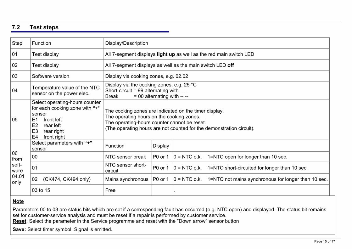
7.2 Test steps
Step Function Display/Description
01 Test display All 7-segment displays light up as well as the red main switch LED
02 Test display All 7-segment displays as well as the main switch LED off
03 Software version Display via cooking zones, e.g. 02.02
04 Temperature value of the NTC sensor on the power elec.
Display via the cooking zones, e.g. 25 °C Short-circuit = 99 alternating with -- -- Break = 00 alternating with -- --
05
Select operating-hours counter for each cooking zone with “+” sensor E1 front left E2 rear left E3 rear right E4 front right
The cooking zones are indicated on the timer display. The operating hours on the cooking zones. The operating-hours counter cannot be reset. (The operating hours are not counted for the demonstration circuit).
Select parameters with “+” sensor Function Display
00 NTC sensor break P0 or 1 0 = NTC o.k. 1=NTC open for longer than 10 sec.
01 NTC sensor short-circuit P0 or 1 0 = NTC o.k. 1=NTC short-circuited for longer than 10 sec.
02 (CK474, CK494 only) Mains synchronous P0 or 1 0 = NTC o.k. 1=NTC not mains synchronous for longer than 10 sec.
06 from soft-ware 04.01 only
03 to 15 Free .
Note Parameters 00 to 03 are status bits which are set if a corresponding fault has occurred (e.g. NTC open) and displayed. The status bit remains set for customer-service analysis and must be reset if a repair is performed by customer service. Reset: Select the parameter in the Service programme and reset with the ”Down arrow” sensor button Save: Select timer symbol. Signal is emitted.
Page 15 of 17

7.3 Fault codes Note: The fault codes are indicated on the timer display The SE fault message can also be displayed briefly if the childproof lock or demonstration circuit cannot be saved.
SE: NTC sensor break or short-circuit or not mains synchronous for longer than 10 sec. See Service programme Test step 04 or 06
FT: Replace electronics module and with FSB back to the factory This message is for the electronics laboratory
BI: Replace electronics module and with FSB back to the factory This message is for the electronics laboratory
EE: EEPROM fault Display only when appliance switched on. The electronics module is defective and must be replaced.
H7: Overheating protection system See chapter 4.1.2
5 “peeps” in rapid sequence
Multiple operation See chapter 4.1.3
The appliance functions except the childproof lock and demonstration circuit.
Page 16 of 17

Page 17 of 17
8 TECHNICAL SPECIFICATIONS
8.1 CK 596
Front left 180 mm 1800 W
Front right 180 mm (can be switched to 180x415)
1800 W (4000 W)
Rear right 180 mm 1800 W
Rear middle 145 mm (can be switched to 145x240)
1000 W (2300 W)
Rear left 145 mm (can be switched to 230 mm)
1100 W 2000 W
Total connections: 10 100 W
8.1.1 Comparative value
It takes approx. 12.5 min. to heat 2 litres of water from approx. 20 °C to 95 °C. On a Hilight heating element 1800 W. (180 mm Ø) Ensure that the voltage is stable at 230 VAC. The cooking utensil must be covered with a lid. 8.1.2 Standby mode
A hotplate with sensor control which is connected to the mains voltage is in standby mode. The electronics module is permanently live. The power consumption is approx. 2 W